FINAL SUMMARY REPORT GER-12842, VOLUME I
b
' I 1 . I I I study 01 EXPANDABLE
TERMINAL DECELERATORS FOR B MARS ATMOSPHERE ENTRY 1
GOODY EAR AEROSPACE CORPORATION AKRON, OHIO
704
JET PROPULSION LABORATORY JPL CONTRACT NO. 951153
3 October 1 9 h Copy No. A %
https://ntrs.nasa.gov/search.jsp?R=19670002392 2020-07-28T16:00:48+00:00Z
GOODYEAR AEROSPACE COR PO R AT IO N
A K R O N IS . OHIO
STUDY O F EXPANDABLE, TERMINAL
DECELERATORS FOR MARS ATMOSPHERE ENTRY,
Volume I - Fina l S u m m a r y Repor t
GER-12842, Rev A 2 1 October 1966
Jay L. Musi l
Goody e a r A e r o s pa c e C o r po rat ion, Akron, Ohio
fo r
Jet Propuls ion Laboratory, California Insti tute of Technology
Pasadena, Calif.
T h b d w u paformed far the Jet pmpllsian Imboratorg, California Institute of Technology, sponsored by the
tion urxiut National Aeronautics and Space Contract NAS7-100.
. .

GER- 12842, VOL I I I I I 1 I I I II I 1 1 I e E 1 1 I
FOREWORD
The r e s e a r c h descr ibed in this f inal s u m m a r y r epor t (Vol-
u m e I) was pe r fo rmed by Goodyear Aerospace Corporat ion,
subs id ia ry of The Goodyear T i r e & Rubber Company, Akron,
Ohio, for the J e t Propulsion Labora to ry , Cal i fornia Inst i -
tute of Technology, under the au thor i ty of Contract No.
951153.
October 1966. M r . J ames M. Brayshaw, J r . , was the
J e t Propuls ion Labora tory Technical Representat ive.
The work was conducted f r o m December 1965 to
The work was performed unde r the gene ra l d i rec t ion of
M r . R. L. Ravenscraf t , manage r of the Aero-Mechanica l
Engineer ing Division and M r . F r e d R. Nebiker , manage r
of the Recovery Systems Engineer ing Department .
p r o g r a m was d i rec ted by M r . Jay L. Musi l , p ro jec t engi-
n e e r .
The
Pe r sonne l contributing to this effor t w e r e M s s r s . A. P. Ahar t ,
configuration, weight, and s t r eng th ana lyses ; K. Birklein
and J. W. Sch lemmer , computer ana lyses ; I. M. Ja remenko ,
p r e s s u r e dis t r ibut ion analyses; and W. W. Sowa, t h e r m a l
ana lyses .
This is Volume I of two volumes.
supporting t e c hnical information.
Volume I1 presen t s the


GER.12842. VOL I
TABLE O F CONTENTS
FOREWORD . . . . . . . . . . . . . . . . . . . . . . . .
LIST O F ILLUSTRATIONS . . . . . . . . . . . . . . . . . . LIST O F TABLES . . . . . . . . . . . . . . . . . . . . . . . Section Ti t le
I DESCRIPTION OF PROGRAM . . . . . . . . . . . 1 . Introduction . . . . . . . . . . . . . . . . . 2 . P r e s e n t Analysis P rocedure for Aerodynamic De-
3 . Analysis Procedure Establ ished f o r P r o g r a m . . ce le ra to r Applications . . . . . . . . . . . . .
I1
111
IV
V
ENVIRONMENTAL CONSIDERATIONS . . . . . . . 1 . Atmospheres and Tra j ec to r i e s . . . . . . . . . 2 . Decelera tor Configurations . . . . . . . . . . ANALYTICAL CONSIDERATIONS . . . . . . . . . . 1 . Basis of Analysis . . . . . . . . . . . . . . . 2 . Decelera tor Weight Relationships . . . . . . .
RESULTS O F ANALYSIS . . . . . . . . . . . . . . 1 . Tra jec to r i e s Considered . . . . . . . . . . .
3 . Decelera tor Weight . . . . . . . . . . . . . .
5 . Effect of Target Mach Number Variat ion . . . .
2 . Decelera tor Size . . . . . . . . . . . . . . .
4 . T e m p e r a t u r e and Mater ia l Considerat ions . . . .
SYSTEM COMPARISONS . . . . . . . . . . . . . 1 . B a s i s fo r Comparison and Selection . . . . . . . 2 . Dynamic Analysis . . . . . . . . . . . . . . .
Page
iii
v i i
xi
2
4
9
9 15
2 1
2 1
22
27
27
27
30
33
42
47
47
49
. V-

Section Ti t le Page
3 . Comparisons of Composite Sys tems. . . . . . . a. G e n e r a l . . . . . . . . . . . . . . . . . b. I tems 1 and 2 - Decelera tor Diameter and Al-
titude a t Mach Number 1. . . . . . . . . . - c. I tems 3 and 4 - Decelerator Weight and En-
velope Weight . . . . . . . . . . . . . . - d. I tems 5 and 6 - Design and Actual Maximum
Decelera tor Envelope T e m p e r a t u r e . . . . . - e . I tem 7 - Auxiliary Gas Inflation Sys tem Weight - f . I tems 8 , 9 and 10 - Ancil lary Equipment
Weight, Attachment Design Saiety F a c t o r , and Packaging Volume . . . . . . . . . . . .
g. I tem 11 - Composite Sys tem Velocity a t 5 , 0 0 0 f t above T e r r a i n . . . . . . . . . .
- h. I tem 12 - Composite System Fl ight-Path Angle a t 5 ,000 ft above T e r r a i n . . . . . .
- i . I tems 13 and 14 - System Oscillation Ampli- tude and Rate. . . . . . . . . . . . . . .
i I tem 15 - Maximum Operating g-Level . . . - k. I tems 16 and 17 - Total Dece lera tor Sys tem
Weight and Weight F rac t ion . . . . . . . .
- -
61 61
61
6 3
64 64
65
66
66
67 67
68
VI RECOMMENDATIONS. . . . . . . . . . . . . . 69
VI1 CONCLUSIONS . . . . . . . . . . . . . . . . . . 73
LIST O F REFERENCES. . . . . . . . . . e . . . 7 5
Appendix
A DECELERATOR CHARACTERISTICS . . . . . . 77
B REFINED POINT- lMASS TRAJECTORY COMPUTA- TIONS AND TRANSIENT HEATING CALCULATIONS . 103
C DYNAMIC STABILITYANALYSES 117 . . . . . . . . .
I I I I I 1 1 I I 1 8 1 1 I I I 1 3
TABLE O F CONTENTS GER-l2842A, VOL I
-vi-
-
Revised 2 1 October 1966

GER-12842, VOL I
LIST O F ILLUSTRATIONS
F igure
1
2
3
4
5
6
7
8
9
10
11
12
13
14
15
Ti t le ~~ ~~ ~~~
Interrelat ionships of Dece lera tor Applications . . . Functional Flow Diagram of Constraining Fac to r s and Va ria ble Pa ram et e r s . . . . . . . . . . . . . . .
Tra jec to r i e s for Mars Atmosphere Ent ry (VM7 Atmos- p h e r e ) . . . . . . . . . . . . . . . . . . . . . . Tra jec to r i e s fo r Mars Atmosphere En t ry (VM8 Atmos- p h e r e ) . . . . . . . . . . . . . . , . . . . . . .
J P L M a r s En t ry Capsule . . . . . , . . . . . . . Tra jec to r i e s f o r Mars Atmosphere En t ry (Atmospheres VM3 and VM4) . . . . . . . . . . . . . . . . . . De c e le ra to r Concepts . . . . . . . , . . . . . . . Drag Coefficient Variation with Mach Number . . . . Decelera tor Weight . . . . . . . . . . . . . . . .
Six Steps f o r Determing Decelera tor Size (All Values a r e Typical) . . . . . . . . . . . . . . . . . . .
Decelera tor Size Requirements (Tra j ec to r i e s A1 and A4; Atmospheres VM7 and VM8) . . . . . . . . . .
Decelera tor Size Requirements (Tra j ec to ry 1 9 and Atmosphere VM8) . . . . . . . . . . . . . . . . Decelera tor - to- Total Weight (Tra j ec to r i e s A1 and A4; Atmospheres VM7 and VM8) . . . . . . . . . . . .
Decelera tor - to- Total Weight (Tra j ec to ry 19 and Atmos- phere VM8) . . . . . . . . . . . . . . . . . . .
Aerodynamic and Thermal Effects on Decelera tor En- velope (Tra jec tor ies 1 9 and A l ) . . . . . . . . .
Page
3
5
11
12
13
14
16
18
2 2
25
28
2 9
31
32
35
- vii -

8 LIST O F ILLUSTRATIONS GER-12842, VOL I
Figure
16
17
18
19
20
2 1
2 2
23
24
25
26
27
28
2 9
B- 1
B-2
B-3
B-4
- viii-
T i t le
Minimum Decelerator Envelope Unit Weight ( T r a j e c - tory A l , hT = 20,000 f t , Dacron) . . . . . . . . .
Minimum Decelerator Envelope Unit Weight ( T r a j e c - tory A l ,
Minimum Decelerator Envelope Unit Weight (Tra j ec - tory 19, hT = 20,000 f t , Dacron) . . . . . . . . . Minimum Decelerator Envelope Unit Weight ( T r a j e c - tory 19, hT = 30,000 f t , Dacron) . . . . . . . . .
Change i n Pe rcen t Total Drag A r e a (Tra j ec to ry 19 and Atmosphere VM8) . . . . . . . . , . . . . . . . Change in Altitude with Variation of Ta rge t Mach Num- be r f r o m 1. 0 (Tra jec tory 19 and Atmosphere VM8).
Variation of Decelerator Weight with Ta rge t Mach Number (Tra jec tory 19; Attached BALLUTE) . . . . Trailing BALLUTE . . . . . . . . , . . . . . . . Attached BALLUTE. . . . , . . . . . . . . . . . Tucked-Back BALLUTE . . . . . . . . . . . . . A I R M A T C o n e . . . . . . . . * . . . . . . . . .
Decelerator Oscillation Charac t e r i s t i cs (Atmosphere VM8; Tra jec tory 19) . . . . . . . . . . . . . . .
Decelerator Oscil lation Charac t e r i s t i c s (Atmosphere VM8; Tra jec tory 2 2 ) . . . . . . . . . . . . . . .
Rocket Boost Technique f o r Simulation T e s t . . . . .
Space/Time and Envelope Trans i en t T e m p e r a t u r e v e r - sus Mach Number (Tra j ec to ry A l ) . . . . . , , , ,
Space/Time and Envelope Trans i en t T e m p e r a t u r e v e r - sus Mach Number (Tra j ec to ry B3) . . . . . . , ,
Space/Time and Envelope Trans i en t Tempera tu re v e r - sus Mach Number (Tra j ec to ry 19) . . . . . . - a
Space/Time and Envelope Trans i en t T e m p e r a t u r e v e r - sus Mach Number (Tra j ec to ry 22) . . . . . . . - I
= 20,000 f t , Nomex) . . . , . . . . . hT
.
Page
38
39
40
41
43
44
46
51
53
55
57
59
60
71
105
107
105
111

8 1 - I 1 1 I I 1
I I I I I s 8 0 E 1
m
LIST O F ILLUSTRATIONS GER-l2842A, VOL I
F igu re
B-5
B-6
c- 1
c-2
c - 3
c - 4
c - 5
C-6
Ti t le
Space/Time and Envelope Trans ien t Tempera tu re v e r - sus Mach Number (Tra j ec to ry 23)
Space/Time and Envelope Trans ien t Tempera tu re v e r - sus Mach Number (Tra j ec to ry 30)
. . . . . . . . .
. . . . . . . . .
Decelera tor Oscillation Charac t e r i s t i c s for Trai l ing BALLUTE (Atmosphere VM7; Tra j ec to ry 22; p = 0. 0 rad /sec) . . . . . . . . . . . . . . . . . . . . . Decelera tor Oscillation Charac t e r i s t i c s for Trai l ing BALLUTE (Atmosphere VM7; Tra j ec to ry 22; p = 0. 5 rad /sec) . . . . . . . . . . . . . . . . . . . . . Decelera tor Oscillation Charac t e r i s t i c s for Trai l ing BALLUTE (Atmosphere VM7; Tra j ec to ry 22; p = 0. 75 rad /sec) . . . . . . . . . . . . . . . . . . . . . Decelera tor Oscillation Charac t e r i s t i c s f o r Trai l ing BALLUTE (Atmosphere VM7; T r a j e c t o r y 22; p = 1. 0 rad /sec) . . . . . . . . . . . . . . . . . . . . . De c e le ra to r Os cilla tion C ha r a c te ri s ti c s fo r Trai l ing BALLUTE (Atmosphere VM8; Tra j ec to ry 19; p = 0 . 5 r a d / s e c ) . . . . . . . . . . . . . . . . . . . . . Decelera tor Oscillation Charac t e r i s t i c s for Trai l ing BALLUTE (Atmosphere VM8; Tra j ec to ry 19; p = 1 . 0 rad /sec) . . . . . . . . . . . . . . . . . . . . .
Revised 2 1 October 1966
Page
113
115
13 1
132
133
134
13 5
136
- ix-


GER- 12842. VOL I
LIST O F TABLES
Table
I
I1
I11
IV
A- I
A- I1
A- 111
A- IV
A-V
A- VI
A- VI1
A- VI11
A- IX
A-X
A-XI
c-I
Ti t le
Charac te r i s t ics of VMAtmospheres . . . . . Init ial En t ry Conditions . . . . . . . . . . . Cases Selected fo r Extended Consideration . . Comparison of Decelerator Sys tems . . . Comparison of Decelerator Charac te r i s t ics . .
Comparison of Decelerator Charac t e r i s t i cs . .
Comparison of Decelerator Charac te r i s t ics . . Comparison of Decelerator Charac te r i s t ics . . Comparison of Decelerator Charac te r i s t ics . . Comparison of Decelerator Charac te r i s t ics . .
Comparison of Decelerator Charac te r i s t ics . . Comparison of Decelerator Charac te r i s t ics . . Comparison of Decelerator Charac te r i s t ics . . Comparison of Decelerator Charac t e r i s t i c s . . Comparison of Decelerator Charac te r i s t ics . .
Manhours and Cost . . . . . . . . . . . . .
. .
. .
. .
. .
. .
. .
. .
. .
. .
. .
. .
. .
. .
. .
. .
. .
Page
10
13
47
62
8 1
83
8 5
8 7
8 9
91
93
95
97
99
101
117
-xi-

GER- 12842, VOL I
SECTION I - DESCRIPTION OF PROGRAM
1. INTRODUCTION
Goodyear Aerospace Corporation (GAC) has conducted a pa rame t r i c study
to de te rmine the suitabil i ty of expandable t e rmina l dece le ra to r s for a
M a r s lander capsule .
J e t Propuls ion Labora to ry (JPL), the study was based on the analytical
formulation of the effects associated with the model environments of
M a r s and specified en t ry capsule cha rac t e r i s t i c s and en t ry conditions.
These effects, charac te r i s t ics , and conditions governed the requi re -
ments for the engineering applications of expandable dece lera tor devices .
Under the t e r m s of Contract No. 951153 f r o m the
The ma in objective was to determine fundamental engineering s y s t e m
design requirements for initial- s tage, expandable dece lera tors that
provide stabil ization and retardation for M a r s lander capsules (the en-
t i r e s y s t e m including the entry vehicle and dece le ra to r is r e f e r r e d to
a s the en t ry capsule) .
is t i c ' s w e r e analyzed:
To fulfill this objective the following cha rac t e r -
1.
2.
3 .
4.
5.
6.
7.
8.
9 .
Structural integrity
Per formance effectiveness
Aerodynamic stabil i ty
Bulk and weight
Heat insulation
Mat e ria Is
Ancillary equipment
Deployment and inflation
P a c kag ing
- 1 -

SECTION I - DESCRIPTION O F PROGRAM GER-12842, VOL I
The final objective was to compare and recommend:
1. Des i rab le configurations
2 . A r e a s of additional study and analysis
3 . Simulation and t e s t r equ i r emen t s
The charac te r i s t ics of var ious expandable dece le ra to r s w e r e de te rmined
by the formulation of uncomplicated s t ra ight forward engineering ana lys i s
and design. Then, des i r ab le dece le ra to r s that r e t a r d capsules to about
Mach 1 n e a r heights of 10, 000 , 20, 000 , and 30 , 000 f t above the Mar t ian
t e r r a i n w e r e se lec ted fo r more-de ta i led ana lyses and invest igat ions.
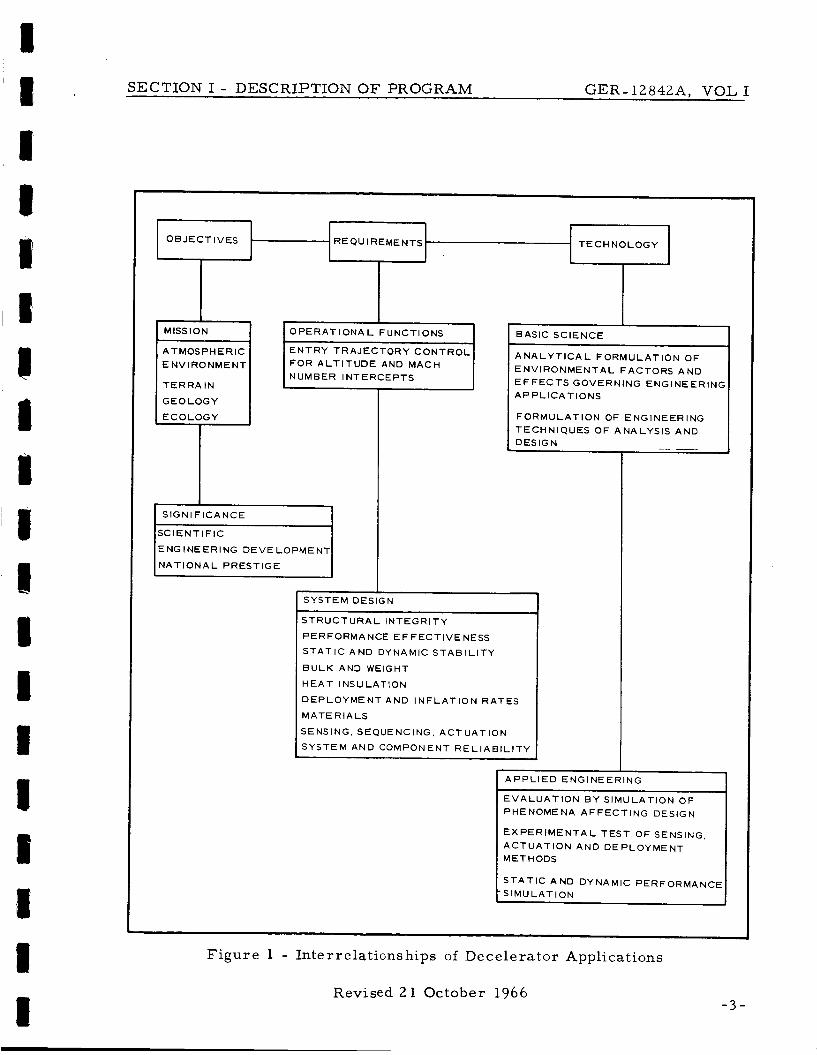
F igure 1 gives the in te r re la t ionship of aerodynamic dece le ra to r appl i -
cations f o r M a r s a tmosphe re en t ry . The r equ i r emen t s and technology
breakdowns assoc ia ted with operat ional functions, s y s t e m design, bas ic
sc ience , and applied engineering a r e re la ted d i r ec t ly to those requi red
under the scope of this p rog ram.
2. PRESENT ANALYSIS PROCEDURE FOR AERODYNAMIC DECELERA- TOR APPLICATIONS
To date aerodynamic dece le ra to r design h a s depended p r i m a r i l y on the
available technology developed f r o m spec ia l ized previous applications
and investigations. The accepted procedure fo r es tabl ishing a design
for a new application is given below.
1 . Survey pe r fo rmance data re la t ing to var ious de-
c e le r a t o r configurations
2 . Evaluate these data to de t e rmine the extent that
a par t i cu la r configuration and operat ing condi-
tions r e l a t e to the specified r equ i r emen t s for the
new application
3 . Conduct a p re l imina ry des ign effor t and build t e s t
models
2
SECTION I - DESCRIPTION OF PROGRAM GER- 12842A, VOL I
O B J E C T I V E S
A
- REQUIREMENTS T E C H N O L O G Y
MISS ION
A TMOS P H E R I C E N V I R O N M E N T
T E R R A I N
G E O L O G Y
A P P L I E D ENGINEERING
E V A L U A T I O N B Y S I M U L A T I O N O F PHENOMENA A F F E C T I N G DESIGN
E X P E R I M E N T A L T E S T OF SENSING,
A C T U A T I O N AND D E P L O Y M E N T METHODS
S T A T I C A N D DYNAMIC PERFORMANCE -S IMU L A T l ON
1 0 P E R A T I ONA L F UNCTl ONS
E N T R Y T R A J E C T O R Y C O N T R O L F O R A L T I T U D E AND MACH NUMBER I NTERCE P T S
SIGN1 F I C A N C E
ENGINEERING D E V E L O P M E N T
N A T I O N A L P R E S T I G E
BASIC SCIENCE I
A N A L Y T I C A L F O R M U L A T I O N O F E N V I R O N M E N T A L FACTORS A N D E F F E C T S G O V E R N I NG ENG I N E E R I NC A P P L I C A T I O N S
F O R M U L A T I O N OF E N G I N E E R I NG TECHNIQUES O F ANALYSIS AND I DESIGN
SYSTEM DESIGN
S T R U C T U R A L I N T E G R I T Y
P E R FORMA NCE E F F EC T I V E NESS
S T A T I C AND DYNAMIC S T A B I L I T Y
B U L K AND WEIGHT
H E A T INSULATION
D E P L O Y M E N T AND I N F L A T I O N R A T E S
M A T E R I A L S
SENSING, SEQUENCING, A C T U A T I O N
SYSTEM AND COMPONENT R E L I A B I L I T Y
Figure 1 - Interrelationships of Decelerator Applications
Revised 21 October 1966 - 3 -
SECTION I - DESCRIPTION O F PROGRAM GER-12842, VOL I
4. Conduct wind- tunnel, functional, and environmental
t e s t s to es tabl ish the validity of the predicted
performance of a specific design f o r the new appli-
cation and operating environments
5. Design, build, and conduct fu l l - sca le , free-fl ight
t e s t s of the dece lera tor s y s t e m under simulated
opera ti ona 1 conditions and environments
This procedure has been demonstrated successfully. However, i t has
been c a r r i e d out too often with the expense of unscheduled, additional
t ime and cost f o r redesign and r e t e s t
countered was the extrapolation of sys t em design data f r o m previous
applications. In many cases and usually a f t e r the p rogram was well
underway, unforseen f ac to r s o r changes made the avialable data in-
adequate o r not applicable. As a r e su l t , in terat ion of Steps 3 , 4 , and
5 was required. Additionally, procedures and t ime s c a l e s es tabl ish-
ing requirements f o r aerodynamic dece lera tor applications w e r e often
incompatible with the development of the m o s t reliable and efficient de-
ce le ra tor sys tem design.
One of the m a j o r difficulties en-
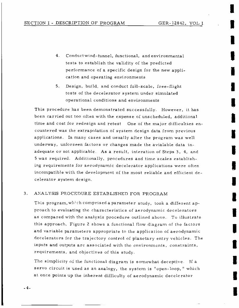
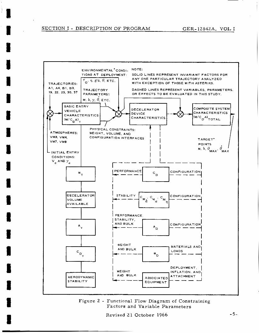
3 . ANALYSIS PROCEDURE ESTABLISHED FOR PROGRAM
This program,whi c h comprised a p a r a m e t e r study, took a different ap-
proach to evaluating the charac te r i s t ics of aerodynamic dece le ra to r s
a s compared with the analysis procedure outlined above. To i l l u s t r a t e
this approach, F igure 2 shows a functional flow d iag ram of the f ac to r s
and var iable pa rame te r s appropr ia te to the application of aerodynamic
dece lera tors for the t ra jec tory control of planetary e n t r y vehicles . The
inputs and outputs a r e assoc ia ted with the envi ronments , cons t r a in t s ,
requi rements , and objectives of this study.
The simplicity of the functional d i ag ram is somewhat decept ive.
s e r v o c i rcu i t is used as a n analogy, the s y s t e m is "open-loop, 'I which
a t once points up the inherent difficulty of aerodynamic dece le ra to r
If a
- 4-
SECTION I - DESCRIPTION O F PROGRAM GER-l2842A, VOL I
ATMOSPHERES:
E NV I RON ME NT AL * c o ND I - NOTE:
T IONS A T DEPLOYMENT: SOLID L I N E S R E P R E S E N T I N V A R I A N T F A C T O R S F O R
P H Y S I C A L CONSTRAINTS: T I I 1 WEIGHT, VOLUME, AND
I q , g'S, 6, E T C . TRAJECTORIES:
I I
I I .a L _. a
A N Y ONE P A R T I C U L A R T R A J E C T O R Y A N A L Y Z E D WITH E X C E P T I O N OF THOSE WITH ASTERIKS.
DASH E D L I N E S R E P R E S E N T V A R I A B L E S , P A R A M E T E R S. OR E F F E C T S T O BE E V A L U A T E D IN THIS STUDY.
COMPOSITE SYSTEM CHARACTERISTICS
CHARACTERISTICS
TARGET* I VM7, VMB
I N I T I A L E N T R Y
C O N D l T IONS:
ve AND Y e
1
ii V O L U M E A V A I L A B L E
AERODYNAMIC S T A B I L I T Y
j i I I
I POINTS
M, h , OMAX, e' M A X
1 _1 I----- r---- I I
WEIGHT I I
-I
I M A T E R I A L S A N D
I
I
U D E P L O Y M E N T , I I N F L A T I O N , A N D A T T AC HME N T
I I
WEIGHT I AND B U L K
----I A SSO C I A T E D E Q U I P M E N T
Figure 2 - Functional Flow Diag ram of Constraining Fac tors and Variable P a r a m e t e r s
Revised 21 October 1966 - 5 -

SECTION I - DESCRIPTION O F PROGRAM GER-12842, VOL I
design technology. "Matching"(that i s , achieving a n optimized design)
the pa rame te r s and f ac to r s for a des i rab le s y s t e m mus t be accom-
plished by techniques similar to the graphic solutions f o r s o m e types of
mathematical equations involving transcendental functions.
In rea l i ty there i s feedback through the dynamic c h a r a c t e r i s t i c s of the
physical system as a r e su l t of coupling through the external operating
environment and the result ing s y s t e m motions.
back is nonlinear by the v e r y na ture of the per formance charac te r i s t ics
of aerodynamic dece lera tor devices when moving through an a tmosphere
a t high speeds, necessitating adaptation of the p a r a m e t e r s to the des i re?
s y s t e m performance.
Unfortunately this feed-
The purpose of this discussion is not to emphasize the difficulty of this
study, but ra ther to demonst ra te the validity of the engineering analy-
sis approach and procedures established F u r t h e r , this analysis
approach was appropriate s ince i t permit ted evaluation fo r all possible
aerodynamic dece lera tor s y s t e m concepts.
A s shown by Figure 2, the significant f ac to r s and p a r a m e t e r s that r e -
quired consideration and evaluation to es tab l i sh the design of deployable
aerodynamic dece lera tor s y s t e m s f o r the M a r s lander capsule included:
1 . Initial e n t r y conditions (V ye , CY,, p , g , r , etc. ) e ' as s ocia ted with the designated JPL t ra j e c to r i e s
( A l , A4 , B1, B3, 19, 22, 23, 3 0 , 3 7 ) and the
charac te r i s t ics of the M a r s a tmosphe re (VM3,
VM4, VM7, VM8)
2 . Basic en t ry capsule s i z e , mass , and per formance
c ha ra c t e r i s t ic s
3 . Physical constraints of e n t r y capsule on the de-
celerator bulk, weight, configuration, a t tach-
ments , e tc .
4. Resulting t ra jec tory p a r a m e t e r s assoc ia ted with
-6-
L

SECTION I - DESCRIPTION OF PROGRAM GER-12842, VOL I
the en t ry capsule (M, h, y, 8, e t c . ) that e s t ab l i sh
the permiss ib le velocity- t ime-d is tance sca l e s
fo r the dece lera tor operat ion
5. Environmental conditions a t deployment (To, q,
g ' s , 8, e tc . ) and operat ion of the dece le ra to r
that es tab l i sh design requi rements f o r per formance
and s t r u c t u r a l integri ty
6 . Dece lera tor charac te r i s t ics as r e l a t ed to pe r -
fo rmance , stabil i ty, weight, and bulk
7. Composite sys t em cha rac t e r i s t i c s
8 . T a r g e t points of Mach number , a l t i tude, angular
excurs ions , and at t i tude r a t e s
The in t e r r e l a t ed f ac to r s and p a r a m e t e r s affecting the application of
aerodynamic dece le ra to r s a r e found to be complex with no d i r ec t o r
p r e c i s e c losed- form solution possible .
effects had to be studied in d i sc re t e , uncomplicated, and o rde r ly fash-
ion and then the s e p a r a t e resu l t s f o r a composite s y s t e m as applied to
representa t ive operat ional cases had to be synthesized.
t ive t rends w e r e established, indicating the m o r e favorable per formance
cha rac t e r i s t i c s , select ions w e r e made . Refined ana lyses and invest i -
gations then w e r e performed leading to the f inal select ion of the con-
cepts and s y s t e m s recommended f o r fu ture full- s ca l e development and
application.
Analysis of the f ac to r s and
Af ter defini-
- 7 -

GER-12842, VOL I
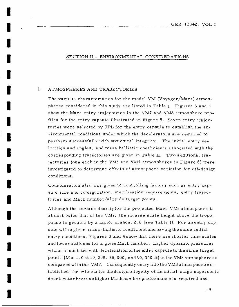
SECTION 11 - ENVIRONMENTAL CONSIDERATIONS
1 ATMOSPHERES AND TRAJECTORIES
The var ious cha rac t e r i s t i c s f o r the model VM (Voyager/Mars) a tmos -
phe res considered in this study a r e l is ted in Table I. F igu res 3 and 4
show the M a r s en t ry t r a j ec to r i e s in the VM7 and VM8 a tmosphere pro-
f i les fo r the en t ry capsule i l lustrated in F igu re 5.
t o r i e s w e r e se lec ted by JPL for the en t ry capsule to es tab l i sh the en-
v i ronmenta l conditions under which the dece le ra to r s a r e requi red to
p e r f o r m successful ly with s t ruc tu ra l in tegr i ty .
loci t ies and angles , and m a s s bal l is t ic coefficients assoc ia ted with the
corresponding t r a j ec to r i e s a r e given in Table 11.
j ec to r i e s (one each in the VM3 and VM4 a tmospheres in F igu re 6 ) w e r e
investigated to de te rmine effects of a tmosphe re var ia t ion for off-design
conditions.
Seven en t ry t r a j ec -
The ini t ia l en t ry ve-
Two additional t r a -
Considerat ion a l s o was given to controll ing f ac to r s such as en t ry cap-
su l e s i ze and configuration, s te r i l i za t ion requi rements , en t ry t r a j ec -
t o r i e s and Mach number/alt i tude ta rge t points.
Although the su r face dens i ty fo r the projected M a r s VM8 a tmosphere is
a l m o s t twice that of the VM7, the inve r se s c a l e height above the tropo-
pause is g r e a t e r by a factor ofabout 2 . 8 ( s e e Table I). F o r a n e n t r y cay-
su l e with a given mass -bal l is t ic coefficient and having the s a m e initial
en t ry conditions, F igu res 3 and 4 show that t he re a r e s h o r t e r t ime s c a l e s
and lower al t i tudes f o r a given Mach number. Higher dynamic p r e s s u r e s
wi l l be assoc ia ted with decelerat ion of the en t ry capsule to the s a m e t a rge t
points (M = 1. Oat 10,000, 20,000, and30,OOO ft) in the VM8 a t m o s p h e r e a s
comparedwi th the VM7.
tabl ished the c r i t e r i a for the des ignin tegr i ty of an in i t ia l - s tage supersonic
dece le ra to r because higher Machnumber per formance is requi red and
Consequently en t ry into the VM8 a tmosphere es-
- 9-

SECTION 11 - ENVIRONMENTAL CONSIDERATIONS GER-12842, VOL I
TABLE I - CHARACTERISTICS O F VM ATMOSPHERES
P r o p e r t y
S u r f a c e p r e s s u r e
S u r f a c e dens i ty
S u r f a c e t e m p e r a tu r e
S t r a t o s p h e r i c t e m p e r a t u r e
A c c e l e r a t i o n of g r a v i t y a t s u r f a c e
Compos i t ion
'O2 (by m a s s )
C 0 2 (by vo lume)
N2 (by m a s s )
N2 (by vo lume)
A (by mass)
A (by vo lume)
M o l e c u l a r we igh t
Spec i f i c hea t of m i x t u r e
Spec i f i c hea t r a t i o
Ad iaba t i c l a p s e r a t e
T r o p o p a u s e a l t i t ude
I n v e r s e s c a l e height ( s t r a t o s p h e r e )
Cont inuous s u r f a c e wind s p e e d
P e a k s u r f a c e wind speed
Des ign v e r t i c a l wind g rad ien t
- 10-
Symbol
PO
TO
= S
g
M
C
Y
P
r
h T
P
V
V m a x
dv/dh
Dim e n s ion
m b
Ib/sq f t
(gm/cu c m ) 1 ~ 5
( s lugs / cu ft)lO 5
K
R
K
R 2 c m / s e c
f t / s ec 2
m o l - '
c a l /g rn C
K/km
R / 1000 ft
k m
ki lo f t
km- f t - 1 5 x 10
f t / s ec
f t / s e c
f t / s ec /1000 f t
V M3
1 0 . 0
20 . 9
I . 365
2 . 6 5
275
495
200
360
375
1 2 . 3
28 . 2
20 . 0
7 1 . 8
80. 0
0 . 0
0 . 0
31 . 2
0 . 230
1 . 3 8
-3. 88
- 2 . 1 3
19 . 3
6 3 . 3
0 . 0 7 0 5
2 . 15
155. 5
3 9 0 . 0
2
Atmosphe
VM4
10 0
20 . 9
2 . 57
4. 98
200
360
100
180
375
1 2 . 3
7 0 . 0
68. 0
0 . 0
0 . 0
30 . 0
32 . 0
42. 7
0 . 153
1 . 4 3
-5 . 8 5
- 3 . 2 1
17 . 1
56. 1
0. 193
5 8 9
155. 5
3 9 0 . 0
2
p ro f i l e
VM7 ~
5. 0
10. 1
0. 68
1 . 32
275
495
200
360
3 7 5
1 2 . 3
28. 2
20. 0
71. 8
8 0 . 0
0. 0
0 . 0
31. 2
0 . 2 3 0
1 . 38
- 3 . 8 8
- 2 . 1 3
1 9 . 3
63 . 3
0 . 0 7 0 5
2 . 1 5
2 2 0 . 0
556. 0
2
V M8
5 0
1 0 . 4
1 32
2 . 56
200
360
100
180
3 7 5
1 2 . 3
1 0 0 . 0
1 0 0 . 0
0 0
0 . 0
0. 0
0 . 0
44. 0
0. 166
1 . 3 7
- 5 . 3 9
- 2 . 96
18. 6
61 . 0
0. 199
6 . 07
2 2 0 . 0
556. 0
2

I 1
100
90
00
T R A J E C T O R Y 22 - TRAJECTORY El -- -
- TRAJECTORY A4 - - -
SECTION I1 - ENVIRONMENTAL CONSIDERATIONS GER-12842, VOL I 1 . 8 1 I I 1 8 I I 8 8 I I I 1 I I
70
60
50.
40
30
m- 0 20 X
k W W LL I
w 10
k O 3
I- -I U
I
'II l o
I I
I 0 1 2 3 4 5 6 7
M A C H N U M B E R
Figure 3 - Trajec tor ies f o r M a r s Atmosphere Entry (VM7 Atmosphere)
- 11-

SECTION I1 - ENVIRONMENTAL CONSIDERATIONS GER-12842, VOL I
I I I I I I 1 1 I I 1 1 1 I 1 1
~
4 ' 0 1 MACH NUMBER
- T R A J E C T O R Y 19
- - - -TRAJECTORY 8 3
2 3 4 5 6 7
Figure 4 - Tra jec to r i e s f o r M a r s Atmosphere E n t r y (VM8 Atmosphere)
- 12 -

SECTION 11 - ENVIRONMENTAL CONSIDERATIONS GER-12842, VOL I
JPL t r a j e c t o r y de s i gna t i o n
A1
A4
B1
B3
19
22
23
30
37
PEii
JF DI
Figure 5 - JPL M a r s En t ry Capsule
TABLE I1 - INITIAL ENTRY CONDITIONS
En t ry velocity, V e
(fps 1
23,000
23,000
15,000
15,000
16,000
16,000
16,000
16,000
23,000
Entry angle, y e (deg)
25
25
15
15
16
16
16
16 '
28
Capsule mass bal l is t i c
p a r a m e t e r , M/C&
(slugs/sq f t )
0. 25
0. 25
0. 5
0. 5
0 .3
0.3
0. 3
0 .3
0 . 3
Atmo s phe r c profile
VM8
VM7 VM7
VM8
VM8
VM7
VM3
VM4
VM8
- 13-

SECTION I1 - ENVIRONMENTAL CONSIDERATIONS GER-12842, VOL I
1 6 0 -
120 '\
0
c
\
ic
160-
120
L \ 3
' B - ATMOSPHERE VM4 T R A J E C T O R Y 30
---I-- A - ATMOSPHERE VM3
T R A J E C T O R Y 23
-t-
- 14-
I

SECTION I1 - ENVIRONMENTAL CONSIDERATIONS GER-12842, VOLI
correspondingly higher a e rodynami c p r e s s u r e loads a r e encountered .
Note that higher driving tempera tures a r e assoc ia ted with the VM7 a t m o s -
sphere a t Mach numbers corresponding with those in the VM8.
in the VM7 a tmosphere the resul ts of ana lyses indicate a t rend toward
considerably lower deployment Mach number requirements for f i r s t - s tage
dece lera tors . This t rend minimizes aerodynamic heating effects a s a
c r i t i ca l design factor for the VM7 en t ry cases considered in this study
(see Appendixes A and B).
specified with a blunted cone configuration, as shown in F igure 5 .
capsule has an included angle of 120 deg and the s i ze and mass cha rac t e r -
i s t ics as tabulated i n F igure 5, corresponding with the designated JPL
t ra jec tor ies .
min imum of interface constraints af t of the capsule base so that a s s e s s -
ment of the var ious decelerator configurations was not unduly r e s t r ic tec
by this consideration. However in te rgra t ion forward f r o m the capsule
base to the payload was beyond the scope of the study and this affect is
not reflected.
However,
For this study a basic en t ry capsule was
The
The study allowed substant ia l volume availabil i ty and a
2. DECELERATOR CONFIGURATIONS
An inflatableAIRMATa cone, extending from the base and para l le l to the
bas ic en t ry vehicle forebody angle and r a m - a i r , , self-inflating BALLUTEa
devices i l lus t ra ted in Figure 7 w e r e considered in this p rogram.
cha rac t e r i s t i c s i z e andweight t rends for these devices w e r e found to be in-
dicative df all expandable, pressure- inf la table devices , including parachutes
and other balloon-like configurations that r equ i r e auxi l iary gas inflation
sources . Only the values fo r the represented cases and configuration studied
wil l change.
The t ra i l ing and attached plain-back BALLUTE configurations a r e shown
in F igure 7 with burble fences about 15 deg aft of the maximum BAL-
LUTE d iame te r . T h e r e a r e var ious aerodynamic and s t ruc tu ra l con- s iderat ions for the use of the fence, one of which is to es tabl ish a
The
~~
a TM, Goodyear Aerospace Corporation, Akron, Ohio.
- 15-

SECTION I1 - ENVIRONMENTAL CONSIDERATIONS GER-12842, VOL I
ATTACHED BALLUTE
TUCKED-BACK BALLUTE
Figure 7 - Decelerator Concepts
point of un i form viscous separat ion near the max imum d iame te r of the
BALLUTE.
sonic speeds, that is, before the c r i t i ca l ( local sonic) Mach number i s
encountered n e a r the max imum BALLUTE diameter , t he re is a possi-
bility of encountering a n a s y m m e t r i c separation effect for a range of
t ransonic Mach numbers near 1. 0.
Although this consideration is associated p r imar i ly with sud-
Additionally the fence provides a substantial portion of the overa l l d rag
of the BALLUTE and can produce the same drag a s a much l a r g e r BAL-
LUTE without a fence. Strength, bulk, and weight requi rements can be
correspondingly l e s s f o r a given d rag effectiveness requirement .
have proved that projections a s high as 10 percent of the BALLUTE
diameter ( r e f e r r e d to a s a 10-percent burble fence) a r e effective.
amount of projection provides a 44-percent i nc rease in relation to the
BALLUTE reference a r e a and a t the same t ime, the des i r ed uni form
viscous separat ion effect is ensured.
T e s t s
This
It is recommended that a similar
- 16-
I I - I I I 8 I i 8 I I I B I I 1 I I I
SECTION I1 - ENVIRONMENTAL CONSIDERATIONS GER-12842, VOL I
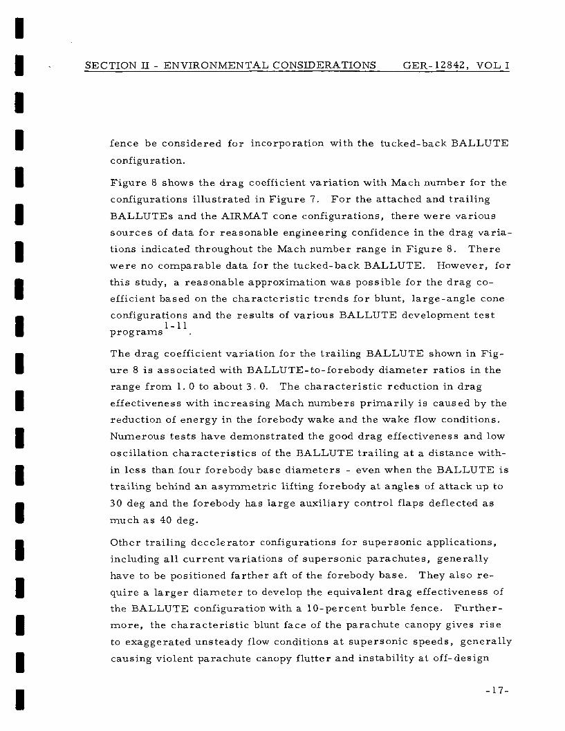
fence be considered f o r incorporation with the tucked-back BALLUTE
configuration.
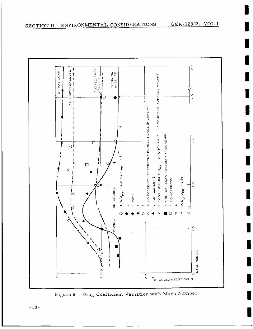
F igure 8 shows the drag coefficient var ia t ion with Mach number fo r the
configurations i l lustrated in F igure 7.
BALLUTEs and the AIRMAT cone configurations, there w e r e var ious
F o r the attached and t ra i l ing
sources of data fo r reasonable engineering confidence in the drag va r i a -
tions indicated throughout the Mach number range in Figure 8 .
w e r e no comparable data for the tucked-back BALLUTE. However, fo r
T h e r e
this study, a reasonable approximation was possible f o r the drag co-
efficient based on the charac te r i s t ic t r ends fo r blunt, large-angle cone
configurations and the resul ts of var ious BALLUTE development t e s t
p r o g r a m s 1-11
The drag coefficient variation fo r the trail ing BALLUTE shown in Fig-
u r e 8 is assoc ia ted with BALLUTE-to-forebody d iameter ra t ios in the
range f r o m 1. 0 to about 3 . 0.
effectiveness with increasing Mach numbers p r imar i ly is caused by the
reduction of ene rgy in the forebody wake and the wake flow conditions.
Numerous t e s t s have demonstrated the good drag effectiveness and low
oscil lation cha rac t e r i s t i c s of the BALLUTE trai l ing a t a distance with-
in l e s s than four forebody base d iameters - even when the BALLUTE is
t ra i l ing behind a n a symmet r i c lifting forebody a t angles of a t tack up to
30 deg and the forebody has la rge auxi l iary control flaps deflected as
much as 40 deg.
The charac te r i s t ic reduction in drag
Other trail ing dece lera tor configurations fo r supersonic applications,
including all c u r r e n t variations of supersonic parachutes , general ly
have to be positioned fa r ther a f t of the forebody base.
qu i re a l a r g e r d i a m e t e r to develop the equivalent drag effectiveness of
the BALLUTE configuration with a 10-percent burble fence. F u r t h e r -
m o r e , the charac te r i s t ic blunt face of the parachute canopy gives rise
to exaggerated unsteady flow conditions a t supersonic speeds, general ly
causing violent parachute canopy f lut ter and instabil i ty a t off- design
They a l s o r e -
- 17-
SECTION 11 - ENVIRONMENTAL CONSIDERATIONS GER-12842, VOL I
I 1 - y 0
I I 0 m
- P P
W 11: 3
LL
W 0 z W LL
W _I
n 3
I- z W 0 rr W
0
'3 1
m
m
a -
W (3 4 n - W > a
I
- k
I
(3 111 0
0 P
0
0
I1
7: I 9 In
I
> i
?
11: b !
I 3 z I u Q I
m
3
~ ~~
Figure 8 - Drag Coefficient Variat ion with Mach Number
- 18-
I I I I I I I I B I I I 1 I I I I I I
I I * I I I I I I I I I I I I 1 I E I I
I
SECTION I1 - ENVIRONMENTAL CONSIDERATIONS GER-12842, VOL I
Mach numbers .
f lated BALLUTE devices during operation p r imar i ly because of (1) m o r e
s teady and uniform flow directed over the s y m m e t r i c a l fo rward portion,
(2) un i form separat ion as a resu l t of the fence, and ( 3 ) st rong damping,
rigidizing, and added m a s s and iner t ia effect of the entrapped inflation
gas a t high stagnation p r e s s u r e (that is, total p r e s s u r e ) ,
This phenomenon i s not assoc ia ted with ram-a i r - in-
The effect of the r i s e r line on the dece lera tor s y s t e m weight was estab-
l ished a s a n important consideration with respec t to the t ra i l ing BAL-
LUTE. This consideration a l so is t rue fo r t ra i l ing parachute decel-
e r a t o r s . The GAC:analyses ( see Appendix A, Volume 11) indicate that
fo r a BALLUTE trai l ing a t a distance of four entry-capsule b a s e d i a m e -
t e r s in the operational environment of in te res t , the weight breakdown
is approximately a s follows: 20 percent fo r the BALLUTE envelope,
33 percent f o r the mer id i an cables , 15 percent f o r the coating (con-
s ider ing both heat insulation and porosity), and 3 2 percent for the r i s e r .
Because of the high percentage of riser weight, a t ra i l ing dece lera tor
m a y weigh more than a n attached dece lera tor even though i t m a y be
s m a l l e r to develop the s a m e total d rag effectiveness.
- 19-
I I I I I I I I I I I I I I I I
I I
a

GER-12842 , VOL I
SECTION I11 - ANALYTICAL CONSIDERATIONS
1 BASIS O F ANALYSIS
To conduct sur face experiments and exploration of Mars effectively,
there will have to be a soft landing with equipment.
able te rmina l dece lera tor f o r a M a r s lander capsule only can be made
by evaluation and a s s e s s m e n t of the constraints of the overa l l mi s s ion
and related sys tems. To obtain a n optimized, expandable, t e rmina l de-
ce l e ra to r , the var ious interrelat ionships of F igu re 2 m u s t be evaluated
within a pa rame t r i c f ramework that allows meaningful tradeoffs.
Selecting an expand-
The requi rement to achieve a ta rge t Mach number and a t a rge t altitude
above M a r s and the evaluation of interrelat ionships in F igure 2 facil i-
tated the understanding of how pa rame t r i c formats and engineering
analysis procedures could be formulated.
w e r e point - mas s t ra jec tory computations, general ized s trength/weight
and configuration ana lyses , d rag pe r fo rmance es t imates , p r e s s u r e dis-
tribution es t imates , mater ia l s investigations, t he rma l ana lyses , and
aerodynamic stabil i ty analyses ( see Volume 11).
The analytical tools used
Decelerator s y s t e m weight has been established as a fundamental factor
i n the application of expandable te rmina l dece le ra to r s .
data, a n integrated tradeoff of dece lera tor weight and en t ry vehicle sys -
t em weight was made .
of allowable Mach number and alt i tude ( o r dynamic p r e s s u r e ) a t deploy-
ment, s i ze , per formance effect iveness , and available operation t imes
to achieve the specified target Mach nurnber/altitude conditions. This
tradeoff a l so took into consideration the vehicle 's
t ics and the operational environments given i n this study.
With appropriate
The dece le ra to r weight was expres sed in t e r m s
physical charac te r i s -
-21-

. _ SECTION I11 - ANALYTICAL CONSIDERATIONS GER-l2842A, VOL I
2 . DECELERATOR WEIGHT RELATIONSHIPS
The weight for a flexible pressure- inf la ted dece lera tor as shown by Fig-
u r e 9 (a l so s e e Appendix A of Volume 11) is related to:
where P is p r e s s u r e ; d, d i a m e t e r ; K a shape fac tor ; and K2, a m a t e r i a l
s t rength fac tor . The p r e s s u r e , P, for a ram-a i r - inf la tab le BALLUTE is
a function of the configuration, dynamic p r e s s u r e , and the flow conditions
of the operating environment. F o r design purposes and s t r u c t u r a l integri ty ,
maximum values of the p a r a m e t e r s corresponding to the deployment con-
ditions general ly a r e employed in any par t icular design application. The p r i m a r y c r i t e r ion is the p r e s s u r e recovery at the ram-air inlets of the de-
v ice .
considerat ion of geometry and position effects, a n a lmos t constant p r e s s u r e
r ecove ry fac tor of 2 . 75 a t the inlets can be achieved f o r deployment Mach
numbers above about 2 . 0.
1’
Numerous t e s t s and ana lyses have shown that by making judicious
-
SHAPE FACTOR 2’ MATERIAL STRE
Figure 9 - Decelerator Weight
- 2 2 - Revised 2 1 October 1966

SECTION I11 - ANALYTICAL CONSIDERATIONS GER-12842, VOL I
In t e r m s of a weight ra t io , i t is shown by Figure 9 that the dece lera tor
weight f ract ion inc reases l inearly with d iameter .
disappointing but well- known effect of the cube/square law fo r s t ruc tu ra l
scaling with increasing size. Additionally, the dece lera tor weight f r ac -
tion is a function of the dynamic p r e s s u r e o r squa re of the Mach number
and is related to the external sur face p r e s s u r e f r o m the aerodynamic
loads that requi res support by the in te rna l p r e s s u r e .
Thus, the dece lera tor weight r e su l t s w e r e developed f r o m s ta t ic a e r o -
dynamic loading relationships with empir ica l ly determined, quas i - s ta t ic
load, tempera ture , and design fac tors employed to account fo r operat-
ing environmental effects and ma te r i a l cha rac t e r i s t i c s . The validity of
this approach has been demonst ra ted by the r e su l t s of this study and has
led to optimum designs of sys t ems with min imum prac t ica l weight.
s ider ing dynamic loading effects, additional weight advantages a r e
gained by delaying the decelerator device deployment to lower dynamic
p r e s s u r e conditions, when time and distance sca l e s pe rmi t , fo r the
following reasons :
This fact re f lec ts the
Con-
1.
2 .
3 .
4.
Energy requirements to deploy and e r e c t the de-
ce l e ra to r a r e reduced since the bas ic vehicle sys -
t e m i s decelerating iner t ia l ly a t a lower r a t e
Snatch loads on the dece lera tor device, support-
ing s t ruc tu re , and vehicle as a r e su l t of lower
relat ive iner t ia l velocit ies a r e reduced
Deployment opening shock and inflation loads as
a r e su l t of lower dynamic p r e s s u r e s a r e reduced
Peak heat flux, integrated heat load, and maxi-
m u m tempera ture r i s e on exposed su r faces of the
dece lera tor a r e reduced because of the lower de-
ployment velocity and shor t e r t ime sca l e s of opera-
tion to a t ta in lower specified t a rge t alt i tude/Mach
number conditions
-23-

I 3 .
SECTION I11 - ANALYTICAL CONSIDERATIONS GER-12842, VOL I
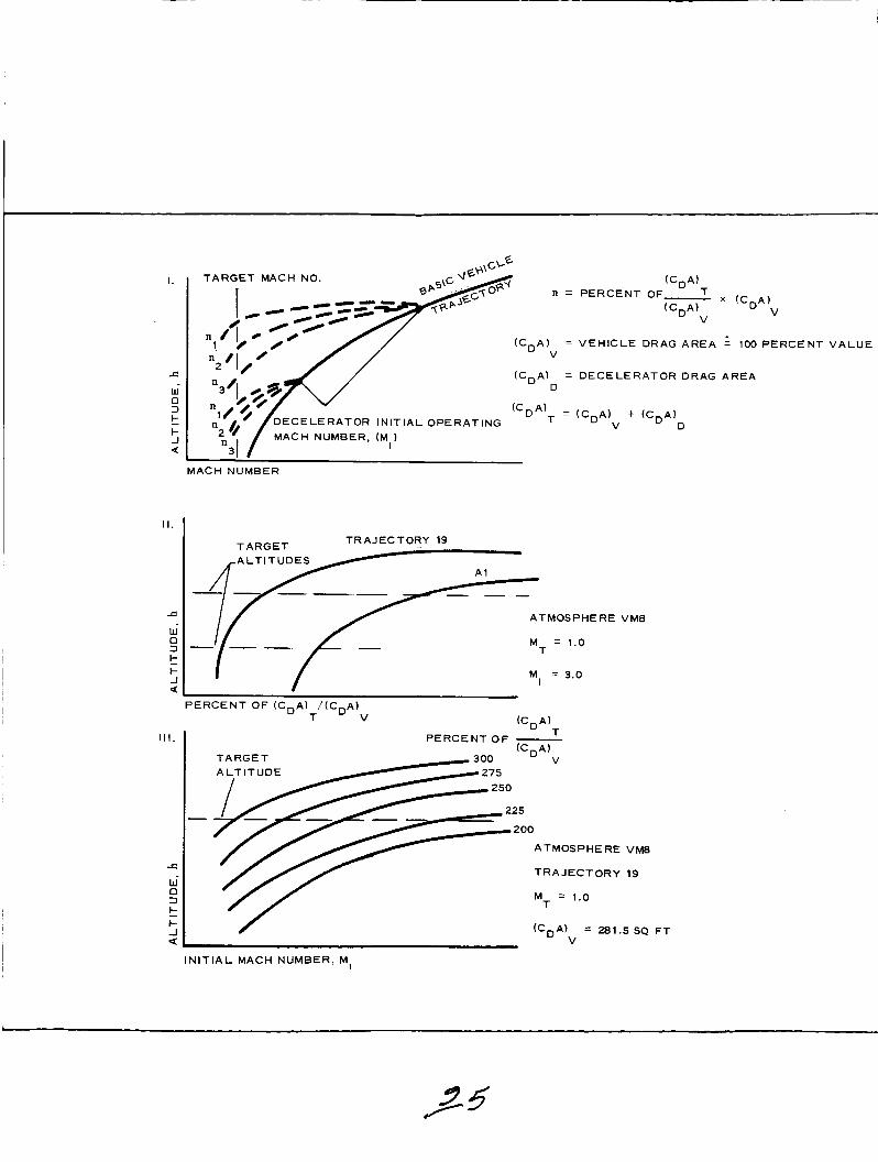
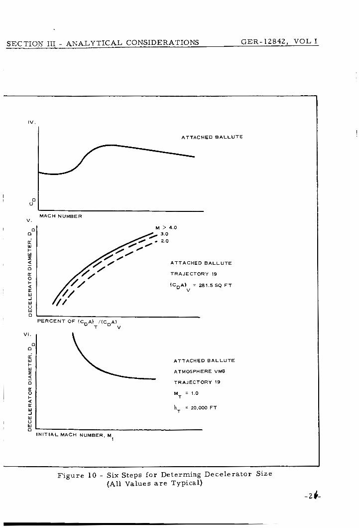
Before specific r e su l t s a r e presented , i t i s des i rab le to es tab l i sh how
the dece lera tor s i ze was de te rmined ( see Section V of Volume 11).
u r e 10 i l lus t ra tes the s i x bas i c s t eps i n the graphic ana lys i s procedure
that lead to a f i r s t approximation determinat ion of the dece le ra to r s i z e
for achieving the t a rge t Mach number/al t i tude.
Fig-
-24-
I I .
c W 0 3
t- -I
t
a
I l l .
c w
t
a
0 3
i- -I
T A R G E T MACH NO.
1 e
t-7 / MACH NUMBER, (M ) I 3
n T A R G E T MACH NO.
n
( C D A )
(CDA)
(C A)
V
D
T
I .
c W 0 3
t- -I Q
k
(cD
CCD
(c D O P E R A T I N G
A )
A)
A)
V
D
T
(CDA)
(CDA)
P E R C E N T OF T
V
V E H I C L E DRAG A R E A
D E C E L E R A T O R D R A G
X (CDA) V
= 1 0 0 P E R C E N T
A R E A
V A L U E
MACH NUMBER
T A R G E T T R A J E C T O R Y 19
A L T I T U D E S A1
A T MOS P H E
M = 1.0 T
M = 3.0 I
P E R C E N T O F ( C D A I / (CDA)
T V (C,A)
R E VM8
P E R C E N T O F - " T
J
T R A J E C T O R Y
M = 1.0 T
VM8
19
( c D N = 281.5 SQ FT V
/ I N I T I A L MACH NUMBER, M,
~ SECTIOV 11; - ANALYTICAL CONSIDERATIONS GER-12842 , V O L I
V I .
0 0
W I- W z
0 [L 0 I-
[L W -I
d
5
a
I V .
A T T A C H E D E A L L U T E
ATMOSPHERE VM8
TRAJECTORY 19
M = 1.0 T
hT = 20,000 FT
A T T A C H E D B A L L U T E
I
MACH NUMBER V .
E l 0
I N I T I A L MACH NUMBER, M I
F i g u r e 10 - Six Steps fo r Determing Decelera tor Size (All Values are Typical)
-26-

GER-12842, VOL I
SECTION IV - RESULTS O F ANALYSIS
1. TRAJECTORIES CONSIDERED
The A l , A4, and 19 t ra jec tor ies specifically a r e considered he re but
the analysis procedures and charac te r i s t ic t rends indicated a r e appro-
pr ia te to all the t ra jec tor ies ( s e e Volume 11). Note that the A1 and A4
t ra jec tor ies have a M/CDA of 0. 25 and a r e assoc ia ted with a higher
init ial entry velocity and s teeper en t ry angle ( f rom Table 11,
23, 000 fps and y e = 2 5 deg)when compared with the other t r a j ec to r i e s ,
except for the 37 t ra jec tory that has the s a m e velocity but a s t eepe r
init ial entry angle of 28 deg and a n M/CDA of 0 .3 . These en t ry con-
ditions m a y be assoc ia ted with lower accu racy constraints for e i ther
orbiting o r flyby en t ry modes of the entry capsule. F o r the cases con-
s idered in this study and a s shown by the t r a j ec to r i e s of F igu res 3 and
4, the sever i ty of environmental conditions encountered a t correspond- ing alt i tudes in a tmosphe re VM8 a r e affected m o r e substantially by
init ial en t ry conditions than by the mass-ba l l i s t ic pa rame te r .
example compare the A1 and 19 en t ry cases a t the alt i tude of30,OOO ft.
It should be recognized that the resu l t s shown l a t e r pertaining to the
A1 t ra jec tory indicate l e s s favorable weight f ract ions for f i r s t - s t age
dece lera tors to achieve the s a m e ta rge t Mach number/alt i tude points
as compared with the 19 t ra jectory.
init ial en t ry velocity (V = 16, 000 fps) and a lower en t ry angle (y =
16 deg) with a higher mass-ba l l i s t ic p a r a m e t e r (M/C A = 0. 3) .
V = e
F o r
The 19 t r a j ec to ry has a lower
e e
D
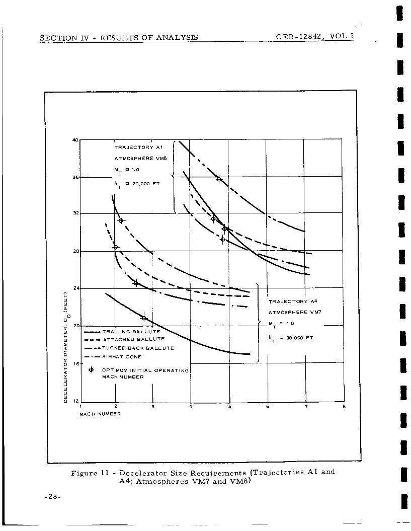
2. DECELERATOR SIZE
The s ix-s tep ana lys i s procedure was used to develop Figures 11 and
12, which establ ish the decelerator s ize r equ i r emen t s to r e t a r d en t ry
capsules in the A l , A4, and 19 t r a j ec to r i e s to a t a rge t Mach number
-27-
SECTION IV - RESULTS O F ANALYSIS GER-12842, VOL I
40
36
32
2E
2r - k W W L. - 0 0
U W + W I
0 K 0 k
K W -1 W u W 0
I!
a
I
T R A J E C T O R Y A1
ATMOSPHERE VM8
MT 1.0
hT 20,000 FT
I-- T R A J E C T O R Y A4
ATMOSPHERE VM7
- - 1 .o M T
- T R A I L I N G B A L L U T E --- A T T A C H E D B A L L U T E - 0- T UC KE D-BA C K B A LL U TE - -0 AlRMAT C O N E *
OPTIMUM I N I T I A L O P E R A T I N G MACH NUMBER
I 1 I
2 3 4 5 6 7 8
MACH NUMBER
Figure 1 1 - Decelera tor Size Requi rements (Tra j ec to r i e s A1 and A4; Atmospheres VM7 and VM8)
- 28-

SECTION IV - RESULTS O F ANALYSIS GER-12842, VOL I
M = 1.0 T
I - - - A T T A C H E D B A L L U T E I ( I _- - TUCKED-BACK B A L L U T E
-. - AIRMAT CONE
O P T I M U M I N I T I A L O P E R A T I N G M A C H N U M B E R
I
Figure 12 - Decelerator Size Requirements (Tra jec tory 19 and Atmosphere VM8)
-29-

of 1. 0 n e a r target a l t i tudes of 20 , 000 and 30 ,000 f t ( s e e Section VI of
Volume 11).
effectiveness a t the corresponding Mach numbers on the a b s c i s s a sca l e .
In o ther words, fo r the f i r s t approximation of dece le ra to r s i z e , t ime
sca l e s f o r dece lera tor deployment and inflation w e r e not requi red to be
ref lected i n these r e su l t s . Note, however, that f o r the corresponding
Mach numbers in the f igures in this sec t ion i l lus t ra t ing the c h a r a c t e r -
i s t i c s of the dece le ra to r s t he re is a s l ight ly higher Mach number (about
5 percent ) and a higher dynamic p r e s s u r e (about 10 percent ) a t which
the dece lera tor device i s deployed ini t ia l ly and begins to inflate ( s e e
I tems 16 and 17 of Tables A- I through A-XI of Appendix A). F igu res 11
and 12 show the t rend to asymptot ic values of dece le ra to r s i z e as Mach
number is inc reased .
The dece le ra to r s w e r e defined a s developing the i r ful l -drag
Thus, this study has pointed out that i n re la t ion to the s i z e of a dece l -
e r a t o r , t he re is a n upper p rac t i ca l l imi t to the ini t ia l operat ing Mach
number . Above this l imi t t he re is no apprec iab le reduction i n decel-
e r a t o r s i ze to achieve lower specified t a rge t Mach number/al t i tude
points fo r the t r a j e c t o r i e s considered in this study.
cu rves assoc ia ted with the t a rge t point Mach number of 1 . 0 and the
20 , 000-ft al t i tude fo r t r a j ec to ry 19, the s m a l l e r dece le ra to r s i z e s a r e
indicated because of the increas ing densi ty of the a tmosphe re .
In comparing the
3 . DECELERATOR WEIGHT
F igures 13 and 14 p resen t the percent of d e c e l e r a t o r weight to total
en t ry capsule weight for the fou r dece le ra to r configurations in t r a j e c -
t o r i e s A l , A4, and 19. The r e su l t s w e r e obtained by the ana lys i s pro-
cedure in Appendix A of Volume 11. F o r these f igu res the dece le ra to r
s t rength requi rements a r e predicated on the u s e of dac ron a s s u m e d to
be operating a t a n elevated t e m p e r a t u r e of 350 F.
design f ac to r of 2. 0 a l s o is re f lec ted i n the r e s u l t s presented .
A m a t e r i a l s t r eng th
When i t i s possible to a t ta in specif ied t a r g e t a l t i tude/Mach number con-
ditions within physical cons t ra in ts and within al lowable t ime and d is tance
SECTION IV - RESULTS O F ANALYSIS GER-12842, VOL I
1 1 I 1 1 1 I I I 1 1 1 I 1 I I I

3 6
32
28
24
20
- 5 16 W U II: W a - 3+ \ 12 0
\ / /
/.4' / 1 '.:>. 0
3
I
W % _1
t- 0
0
k-
c,
a
?
L 0 I-
K W -I W u W
a
n
SECTION IV - RESULTS O F ANALYSIS GER- 12842, VOL I I * -
I 1 I ' I I t I I 1 I 1 I 1 I; t 1 R
T R A J E C T O R Y A1
ATMOSPHERE VM8
M = 1.0 T
T R A J E C T O R Y A 4
ATMOSPHERE VM7
- M = 1.0 T
-e-- - - -- 1 2 3 4 5 6 7
MACH NUMBER
~ ~
Figure 13 - Decelerator- to-Total Weight (Tra j ec to r i e s A1 and A4; Atmospheres VM7 and VM8)
-31-

32
28
24
20
- k
W U U W
z 16
a - I- 3 “o 12
3
I
W 3 -I d I- O
0
i 2
?
z 0 I- 4 [L W -I W V W 0
/ T R A I L I N G B A L L U T E I
. !
-_--- MT :- l o
h T = 30,000 F T
--- - A T T A C H E D B A L L U T E
---- TUCKED-BACK B A L L U T E
-e- A I R M A T C O N E
@ O P T I M U M I N I T I A L O P E R A T I N G MACH NUMBER
N O T E
BASED O N D A C R O N
A T 350 F
E 11 1 1 I 1 1 1 I 1 1 I I 1 I 1 I I R
.. SECTION IV - RESULTS OF ANALYSIS GER-12842, VOL I
1 2 MACH NUMBER
3 4 5 6 7
Figure 11 - Decelera tor - to-Tota l Weight ( T r a j e c t o r y 19 and Atmosphere VM8)
-32-
SECTION IV - RESULTS O F ANALYSIS GER-12842, VOL I
sca l e s , F igures 11 through 14 indicate that i t is des i rab le to accept a
l a r g e r dece lera tor diameter and delay operation of the device to a cor -
responding lower Mach number. This consideration leads to the t rend
of a r r iv ing a t a minimum percentage of dece lera tor - to-total s y s t e m
weight and corresponding optimum init ial operating Mach number .
t r a j ec to ry 19 in Figure 14 and the ta rge t conditions of Mach number =
1. 0 and altitude = 20, 000 ft , the s a m e t rends a r e indicated. However
as a r e su l t of the extended available t ime and dis tance sca l e s andh ighe r
a tmosphe re density, the values for the dece lera tor s ize , weight f ract ion,
and operational Mach number a l l a r e reduced substantially as compared
with the requi rements for the 30, 000-ft t a rge t alt i tude case . The in te r -
action of Mach number effect (that i s , dynamic p r e s s u r e ) on the decel-
e r a t o r s t rength and weight requirements has a compounding effect.
F o r
4. TEMPERATURE AND MATERIAL CONSIDERATIONS
Figure 15 has been developed by the analysis procedure of Section IV
of Volume I1 to indicate the degree of validity in choosing dacron when
operating a t a tempera ture of 350 F for the dece lera tors analyzed and
in leading to the resu l t s presented in F igures 13 and 14 for t r a j ec to r i e s
A1 and 19. The the rma l requirement curves for dacron and Nomex for
t r a j ec to ry A1 rep resen t the envelope fabric weight p e r unit area re -
quired to l imit the total t empera ture r i s e to 350 F with dacron and600 F
with Nomex. These curves cor respond with the dece lera tor s i zes in
F igures 11 and 12 that begin effective operation a t the corresponding
Mach number on the absc issa sca le .
sul ts f r o m the local heat flux and integrated heat load corresponding
with the velocity- t ime-dis tance sca l e s (appropriate to init ial operating
conditions fo r the dece lera tors ) to achieve the t a rge t points of M
1. 0 and hT = 20, 000 ft.
a s s u m e d that the local heat flux is 0. 30 of the stagnation point value.
The m a t e r i a l t e m p e r a t u r e r e -
=
The analyses ( see Section I1 of Volume 11) T
Boundaries for both 30 , 000- and 20,000-ft t a rge t alt i tudes fo r t ra jec-
to ry 19 have been included in F igu re 15 to indicate the effect of a lower
-33-

SECTION IV - RESULTS O F ANALYSIS GER-12842, VOL I
ta rge t altitude requirement . F o r the lower ta rge t alt i tude, t he re a r e
assoc ia ted lower opt imum init ial operating Mach number requi rements
with the resulting f a c t that aerodynamic heating effects a r e minimized .
At the higher init ial operating Mach numbers for this ta rge t alt i tude,
l a r g e r values fo r the fabr ic unit weight a r e required as a r e su l t of the
extended time sca l e s of operation and consequent i nc rease in total heat
load in addition to the effect of the higher values of Mach number . To
develop the thermal requi rement cu rves , the heat absorbed by the de-
ce le ra tor ma te r i a l was a s s u m e d simply to be that of i t s heat capacity.
In F igure 15 a r e the curves of dece lera tor envelope fabr ic weight p e r
unit a r e a for the attached and t ra i l ing BALLUTE dece le ra to r s estab-
l ished by aerodynamic loading requi rements . T h e r e a r e symbols for
the other configurations a s de te rmined a l s o by the aerodynamic load-
ing encountered at the corresponding ini t ia l operating Mach number to
achieve the desired ta rge t point conditions.
t a rge t conditions of M = 1. 0 and hT = 2 0 , 0 0 0 ft , i t is shown that the
u s e of dacron a t a 3 5 0 - F "s ta t ic" t e m p e r a t u r e fo r the AIRMAT cone
(initially operating at the indicated opt imum Mach number f r o m Fig-
u r e s 13 and 14) i s conservat ive.
assumpt ion of dacron a t 350 F is quite accu ra t e ; f o r the t ra i l ing and
tucked-back BALLUTEs , the assumpt ion is opt imist ic .
F o r t r a j ec to ry A1 with
T
F o r the attached BALLUTE, the
It is pointed out h e r e that the s ta t ic strength/weight ana lys i s and the
the rma l analysis did not include provision f o r coating weight. Some
coating m u s t be provided in any event to ensu re min imum acceptable
leakage ra tes to maintain the des i r ed p res su r i za t ion within the decel-
e r a t o r envelope.
a r e a l s o good heat insulating ma te r i a l s ( s e e Section I11 of Volume 11).
A nominal coating thickness of about 0. 01 psf of Vitron o r Neoprene
will provide a net porosi ty of about 0. 02 cu ft /sq f t / sec , which i s a n
acceptable value based on exper imenta l r e s u l t s f o r the upper values
of p r e s s u r e ratios and operating envi ronment encountered in this study.
Typical coating m a t e r i a l s employed fo r this purpose

0.15 I
0.1
- I- O 0 ll.
W r 3 a
s: K W
cn z 3 0
a n
a a - \ z 4 W U 4
z 2 K W
I- I
W 3
k
a
13
0.2
0.15
0.1
0.05
M A C H N U M B E R
35
RY A1
- - AERODYNP L O A D R E Q U I R E M E N T
3 IACH NUMBER

~ SECTION IV - RESULTS O F ANALYSIS GER-12842, V O L I
L O A D R E Q U I R E M E N T
T R A I L I N G B A L L U T E
i+,;OMEX A T 60: F 1 + - D A C R O N A T 350 F
% T R A I L I N G B A L L U T E
0 A T T A C H E D B A L L U T E
+ TUCKED-BACK B A L L U T E
A AIRMAT CONE
A h = 20.000 FT AND M = 1.0
h = 30,000 FT AND M = 1.0
T T
T T
- DACRON A T 350 F
- - - NOMEX A T 600 F
Figure 15 - Aerodynamic and Therma l Effects on Decelera tor Envelope (Tra j ec to r i e s 1 9 and AI)
4% - 3 4 -

SECTION IV - RESULTS O F ANALYSIS GER-12842, VOL I
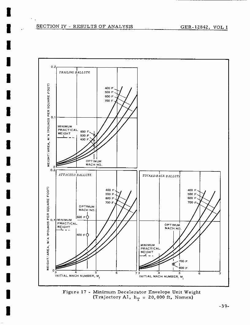
F igures 16 through 19 present curves to es tabl ish a m o r e refined e s -
t imate fo r the minimum required dece lera tor envelope unit weight that
would be compatible with both the aerodynamic heating and aerodynamic
loading environment fo r the seve ra l en t ry cases considered in this study
(also s e e Section VI of Volume 11). Each figure i s assoc ia ted with the
dece lera tor configurations that provide decelerat ion of the basic en t ry
capsule to % = 1. 0 nea r the ta rge t alt i tude specified on the f igures .
each f igure i s the callout "optimum Mach no. , I' which is associated
with a minimum percentage of dece lera tor - to- total en t ry capsule weight.
In
On the ordinate in these figures is the callout "min imum prac t ica l
weight", which is the minimum weight of the envelope fo r each of the
dece lera tor types. The thermal requi rement curves a r e l imited to a
maximum tempera tu re of 450 F for dacron and 700 F for Nomex.
symbols fo r each decelerator located on the "opt imum Mach no. I ' line
cor respond to the envelope ma te r i a l thickness requi red to sustain the
aerodynamic loading a t the indicated tempera ture .
p rac t ica l weight" includes provision fo r a coating of 0. 01 lb/sq ft of
Neoprene o r Vitron to give the dece lera tor envelope a low value of po-
rosi ty .
specific heat as the envelope ma te r i a l , which i s a valid assumpt ion ( see
Section I11 of Volume 11).
The
The "minimum
F o r this study i t is a s sumed that the coating has the s a m e
The fabric weight pe r unit a r e a is in re ference to the thin envelope of
the dece lera tor device.
to total dece lera tor weight (see Appendix A of Volume 11) is nominally
20 percent for the t ra i l ing BALLUTE, 38 percent for the attached BAL-
LUTE, and 10 percent fo r the tucked-back BALLUTE.
MAT cone, the envelope compr i se s about 67 percent of the total ex-
pandable dece lera tor weight.
the period of the significant heat pulse is of the o r d e r of 5 s e c ( see
Section I1 of Volume I1 and Figures B-1 through B-6 in Appendix B).
In this in te rva l the speed of the en t ry capsule will have been reduced
The proportion of dece lera tor envelope weight
F o r the AIR-
F u r t h e r m o r e for the cases under study,
-37-

SECTION IV - RESULTS O F ANALYSIS GER-12842, VOL I
I- O 0 LL W K Q 3
8 K W
m 0 Z 3 0
a
a a
a
- \ z
W K Q
I- I
W 3
\
!2
I
k 0 0 LL W K Q 3
8 0: W
m 0 Z 3 0
Q
3
W K a
I
W 3
a
a - \-
a
.. 6 :
0.3
0.2
0.1
0
MACH NO.
0.2
0.1
0
Y 2 3 4 5 6 7 I N I T I A L MACH NUMBER, MI
I I I
,MACH NO.
A I R M A T C O N E
I I
~ . . . . . . . . . . - . . . P R A C T I C A L
2 3 4 5 6 7
I N I T I A L MACH NUMBER. MI
~ ~ ~~~
Figure 16 - Minimum Decelera tor Envelope Unit Weight (Tra jec tory A l , hT = 20,000 ft , Dacron)
- 3 8 -
SECTION IV - RESULTS O F ANALYSIS GER-12842, VOL I
0.2
- I- O 0 LL W U 3 a
5: U W ; 0.1 0 Z 3 0 a a
d
a
'3
3 0
- \ %
W K
I- I
W
\
0.2
I- 0 0 LL W U 3 a
5: U W
u) 0 z 3 0
a 0.1
a a
d
a
'3 S o
- \ 3
W U
I- I
W
\
I TRAILING B A L L U T E
MINIMUM PRACTICAL 6ooF
MACH NO.
A T T A C H E L IALLUTE
0 P T IMUM MACH NO
00 F b MINIMUM PRACTICAL WEIGHT
4
- TUCKED-BACK B A L L U T E
400 F. 500 F, 600 F,
MINIMUM PRACTICAL
6 7 3 4 5 6 INITIAL MACH NUMBER, MI IN IT IAL MACH NUMBER, M,
Figure 17 - Minimum Decelerator Envelope Unit Weight (Tra jec tory A l , hT = 20,000 f t , Nomex)
-39-

SECTION IV - RESULTS O F ANALYSIS GER-12842, VOL I
0.3 I T U C K E D - B A C K B A L L U T ~ I I
L N J R I I I-
- 40-
2 3 4 5 IN IT IAL MACH NUMBER. MI
A T T A C H E D B A L L U T E m OPTIMUM MACH NO. I I
I I AlRMAT C O N E 1
OPTIMUM MACH NO.
2 3 4 5 IN IT IAL MACH NUMBER, MI
Figure 18 - Minimum Dece le ra to r Envelope Unit Weight (Tra j ec to ry 19 , h - 20, 000 f t , Dacron) T -

I- O 0 LL W [L
3 a
s:
3
(L W a
Z 3 0 a a
d
- \ z
w U a I- I u W 3
\
-
- I- O 0 LL W K 3 a
U W
v) 0 Z 3 0
a
a a
d
- \ 3
W K a I- S
W B
\
!?
0.3
0.2
0.
0
TRAILING B A L L U T E 1
/ I l l
0.3 T U C K E D - B A C K B A L L U T E
0.2
0.1
n
MINIMUM PRACTICAL WEIGHT
SECTION IV - RESULTS O F ANALYSIS GER-12842, VOL I
d 8 1 I 1 i 1 1 I i t i I 8 8 8 I
I
- 2 3 4 5 6 7
I N I T I A L MACH NUMBER, M,
A T T A C H E D B A L L U T E I I 1
MINIMUM P R A C T I C A L WEIGHT
I I / / f
A I R M A T C O N E I I
MINIMUM P R A C T I C A L
2 3 4 5 6 7 I N I T I A L MACH NUMBER, MI
Figure 19 - Minimum Decelerator Envelope Unit Weight (Trajectory 1 9 , hT = 30 ,000 ft, D a c r o n )
-41-

SECTION IV - RESULTS O F ANALYSIS GER-12842AY VOL I
significantly and the corresponding aerodynamic loads will be smaller
by the t ime the m a t e r i a l r eaches the a s s u m e d elevated operat ing tem-
pe ra tu res used in this study (note F igu res 16 through 19). Thus, i t is
indicated (see I tem 1 1 , Tables A-I through A-XI of Appendix A) that
fo r the dece lera tor envelope with coating thickness based on acceptable
leakage ra te and heat insulation, reasonable dece lera tor weight f r a c -
tions can be obtained.
5. E F F E C T O F TARGET MACH NUMBER VARIATION
The determinat ion of how the dece le ra to r s i z e and t a rge t alt i tude a r e
affected by the ta rge t point Mach number as i t v a r i e s f r o m 0. 7 to 1 . 5
is important as relating to s i ze and per formance operating to le rances .
F igu res 2 0 and 2 1 i l lus t ra te these effects for t r a j ec to ry 19 . Cons ide r -
ing the effect on s i ze (F igu re 20), increas ing the t a rge t Mach number
to 1. 4 reduces the requi red total s y s t e m d r a g a r e a by about 100 p e r -
cent f r o m the value requi red a t Mach 1. 0.
r e f e rence point (the z e r o value on the ordinate sca le of F igu re 20) for
t r a j ec to ry 19, the percentage of total s y s t e m d rag a r e a to the en t ry
capsule drag a r e a i s requi red to have a nominal value of about 500 p e r -
cent to attain a n M
1. 4 a t 30 , 000 ft, the percentage of dece le ra to r d r a g a r e a to the en t ry
capsule drag a r e a can be reduced to about 400 percent . In this c a s e ,
this reduction i s the s a m e a s decreas ing the dece le ra to r d i ame te r by
about 10 percent for a n ini t ia l operat ing Mach number of 3 . 0.
t rend is for a s m a l l e r reduction in s i ze with higher init ial operat ing
Mach number.
At the Mach number 1. 0
- T - 1. 0 a t 30, 000 f t . If the MT i s i nc reased to
The
On the other hand f o r a lower t a rge t Mach number of 0 . 7 , a 10-per -
cent i nc rease in dece le ra to r s i ze is indicated.
while assuming a constant value of d r a g coeff ic ient fo r the s y s t e m ,
which is optimistic compared with the c h a r a c t e r i s t i c lower d rag co-
efficient of bodies a t subsonic veloci t ies .
numbers , the effect of the ini t ia l operat ing Mach number is nominal.
This i n c r e a s e is made
At the subsonic t a rge t Mac11
-42 - Revised 21 October 1966

160
120
80
40
0
I1 -80 t- E + 4
I- - 0 -120 u - -
\ I- - a 0 u
Y
- 1 6 0
SECTION IV - RESULTS OF ANALYSIS GER-12842, VOL I 1 . I 1 1 I 1 I 8 I I I I I I I I I I
0 . 6 0 .E 1 .o 1.2 1.4 1.6
T A R G E T MACH NUMBER, M T
Figure 2 0 - Change in Percent Total Drag Area (Tra j ec to ry 19 and Atmosphere VM8)
- 4 3 -

SECTION IV - RESULTS O F ANALYSIS GER-12842, VOL I
- 8,000 I
t W W LL - s - 10,000 W u z 6 x u 0 3
- 12,000
I i I
I
I
I- -I 4 - 1 4 , 0 0 0
0 . 6 0.8 1 .o 1.2 1.4 1.6
T A R G E T MACH NUMBER, M I T
Figure 21 - Change in Altitude with Variat ion of T a r g e t Mach Number f r o m 1. 0 (T ra j ec to ry 1 9 and Atmosphere VM8)
- 44-

I I I I I I I I I 1 I 1 I I I I I I I
SECTION IV - RESVLTS O F ANALYSIS GER-12842, VOL I
The effect of ta rge t point Mach number variation on alt i tude shows that
i f the ta rge t Mach number is allowed to inc rease above 1 . 0, there i s
a n incrementa l gain in target alt i tude.
d e c r e a s e s with decreasing values of ta rge t point Mach number .
Conversely the t a rge t alt i tude
A higher init ial operating Mach number resu l t s in a n additional gain in
alt i tude p r imar i ly because the higher Mach number is a l so associated
with a higher init ial operating altitude ( see Step 1 in Figure 10). F o r
lower ta rge t Mach numbers a higher init ial operating Mach number
causes loss in alt i tude. This loss occurs because of the lower air den-
s i ty corresponding with the higher alt i tude a t which the re ference ta rge t
Mach number of 1 . 0 is attained and because the required dece lera tor
d rag a r e a corresponding with the higher init ial operation Mach number
a l s o i s sma l l e r .
F igure 22 i l lus t ra tes the t rend of dece lera tor - to- total en t ry capsule
weight as a function of target Mach number variation with ta rge t altitude
as a p a r a m e t e r fo r t ra jec tory 19.
the absc i s sa sca le i s the Mach number to which the en t ry capsule de-
ce l e ra t e s without an auxiliary dece lera tor . F o r t r a j ec to ry 1 9 i t is in-
dicated that fa i r ly low values of subsonic Mach number can be attained
fo r dece lera tors weighing l e s s than 10 percent of the total en t ry capsule
weight.
t r a j ec to ry 19, substant ia l weight penalt ies a r e incur red r ega rd le s s of
ta rge t a1 t i tude.
The intersect ion of the curves with
To achieve ta rge t Mach numbers of l e s s than about 0. 4 fo r
- 45-

SECTION IV - RESULTS O F ANALYSIS GER-12842, VOL I
I I I
h = TARGET ALTITUDE T
r- 0 I
w % J
I- O
0
U 0 l-
U W -I W u W 0
a
? ?
a
T A R G E T MACH NUMBER, M T
tl ---I-
1.2 1.4 1 .6 1.8 2.0
Figure 22 - Variation of Dece lera tor Weight with T a r g e t Mach Number (Tra j ec to ry 1 9 ; Attached BALLUTE)
-46-
I I 1 I I I I 1 I I I I I 1 1 I I I I
~~ ~~ ~

GER-12842, VOL I
SECTION V - SYSTEM COMPARISONS
1. BASIS FOR COMPARISON AND SELECTION
The compar ison and subsequent selection of dece lera tor configurations
and their su i tab le a r e a s of application for final study and ana lys i s w e r e
facil i tated by a tabulation scheme.
with each of the four decelerator configurations fo r the var ious en t ry
c a s e s under study w e r e evaluated as shown in Tables A - I throughA-XI
in Appendix A.
that es tabl ish rea l i s t ic total dece lera tor s y s t e m weight es t imates and
that w e r e n e c e s s a r y for use with the dynamic computer ana lyses .
Thir ty separa te f ac to r s assoc ia ted
The tabulation includes those engineering design fac tors
Seventeen cases w e r e selected as indicated in Table I11 below, for r e -
f ined point - ma s s t ra j e c to r i e s t ha t inc o r po r a t ed a t r a n s i en t ,
analysis p r o g r a m to determine m o r e real is t ical ly the t e m p e r a t u r e to
which the fabr ic of the dece lera tor envelope will be subjected.
u r e s B-1 through B-6 in Appendix B show the r e su l t s of the refinedpoint-
m a s s t ra jec tory computations and t rans ien t heating calculations.
heating
.Fig-
TABLE I11 - CASES SELECTED FOR EXTENDED CONSIDERATION
Decelera tor Configurations
numb e r (ft x 103) TB AB TBB AC
Targe t t r a j ec to ry alt i tude -c------
X X 20 I
20 ' x X X
19 20 X X X X
22 30 X X X X
23 30 X X
30 20 X X
- 47-

I SECTION V - SYSTEM COMPARISONS GER-12842, VOL I
The select icn of the en t ry cases in Table I11 for extended ana lyses was
considered appropriate s ince these cases encompass the broad range
of p a r a m e t e r s assoc ia ted with the study, including: (1 ) mass bal l is t ic
p a r a m e t e r , s i ze , and weight of en t ry capsule , ( 2 ) in i t ia l t r a j ec to ry con-.
dit ions, ( 3 ) Mars a tmosphere prof i les , and ( 4 ) the four bas ic expandable
dece le ra to r configurations. Thus, a reasonable a s s e s s m e n t of the e f fec t
these p a r a m e t e r s have on the cha rac t e r i s t i c s of expandable t e r m i n a l
dece le ra to r s could be made .
s ince all the dece le ra to r configurations w e r e evaluated fo r these two
t r a j e c t o r i e s , including the dynamic s tabi l i ty ana lyses . These t r a j ec -
t o r i e s a r e considered the m o r e appropr i a t e fo r the ea r ly M a r s lander
mis s ions and, as wil l be d i scussed , show that expandable t e r m i n a l de-
ce l e ra to r s can provide des i r ab le s y s t e m pe r fo rmance with reasonable
weights within cu r ren t expandable dece le ra to r technology.
T r a j e c t o r i e s 1 9 and 2 2 w e r e emphas ized
The refined point-mas s t r a j ec to ry computations included provis ion fo r
a l inear i nc rease in dece le ra to r d rag a r e a f r o m init iation of deploy-
ment to full inflation during a n in te rva l of 1 . 5 s e c .
inflation in te rva l and l inear d rag a r e a var ia t ion w a s based on exper i -
ence with r a m - a i r inflated BALLUTEs for the Mach number and dy-
namic p r e s s u r e range of c u r r e n t i n t e r e s t .
off considerations of a minimum d e s i r e d t ime to achieve ful l -drag effec-
t iveness and low opening shock and to avoid m a t e r i a l fatigue f a i lu re as
a r e su l t of f lut ter during the inflation in te rva l .
The choice of this
This choice includes t r ade -
With the ram-a i r - inf la ted configurations, the s i z e and number of the
inlets m u s t provide the requi red m a s s flow into the dece le ra to r envel-
ope consistent with the dece le ra to r i n t e rna l volume and the inflation
in te rva l of 1. 5 s e c .
gas inflaticn sou rce , gas p r e s s u r e , gas volume, valve s i z e s , and
valve numbers a l s o m u s t be compatible wi th the inflation in t e rva l of
1. 5 s e c .
For the 120-deg AIRMAT cone with a n auxi l ia ry
Layout drawings of se lec ted dece le ra to r /veh ic l e combinations fo r the
- 48-
I I 1 1 1 I I I
I P I I I I I D
a

SECTION V - SYSTEM COMPARISONS GER-12842, VOL I
four dece lera tor configurations under study w e r e made a s shown in Fig-
u r e s 23 through 26.
ment , deployment requirements , and constraints was gained. Addi-
tionally rea l i s t ic weight es t imates fo r the anc i l la ry equipment assoc ia ted
with these i tems w e r e obtained as tabulated in these f igures .
packaged volume requirements a r e not beyond the range of prac t ica l
considerations ( see Item 13 of Tables A - I through A-XIinAppendix A) .
F r o m these a n a s s e s s m e n t of the packaging, attach-
Note that
As i l lust rated in the layout drawings of F igures 23 through 26, Marmon
c lamps accompl ish attachment and separat ion functions of the var ious
dece lera tor devices and associated equipments.
significantly l ighter and has l e s s bulk with higher reliabil i ty and uni-
formi ty in accomplishing separation functions. F u r t h e r m o r e , this
a t tachment method is suitable for all the dece lera tor concepts includ-
ing the trail ing dece lera tors .
the capsule base and the confluence point of the r i s e r a r e attached to
the ring as i l lustrated in Figure 23.
men t s a r e s imple with a minimum of pa r t s .
for this method of attachment fur ther lend themselves to simplifying
the s ter i l izat ion of this assembly.
The Marmon c lamp is
In this ca se the suspension l ines between
Additionally the a s s e m b l y requi re -
All of these cha rac t e r i s t i c s
2. DYNAMIC ANALYSIS
Dynamic stabil i ty charac te r i s t ics for each of the four dece lera tor con-
figurations for the 19 and 22 t r a j ec to r i e s w e r e analyzed.
of attached dece lera tor configurations, a s ix-degree-of - f reedom com-
puter p rogram was used (see Appendix B of Volume 11) for the formu-
lation of the dynamic stability analysis .
two additional degrees of f reedom w e r e included.
In the case
F o r the t ra i l ing BALLUTE
F igures 27 and 28 show the oscil lation cha rac t e r i s t i c s for each of the
four bas ic dece lera tor configurations a s applied to the 19 and 22 t r a -
jec tor ies .
kinematic coupling between rolling velocity and angle of a t tack caused
In the case of the t ra i l ing dece le ra to r s , the effect of the
- 49-
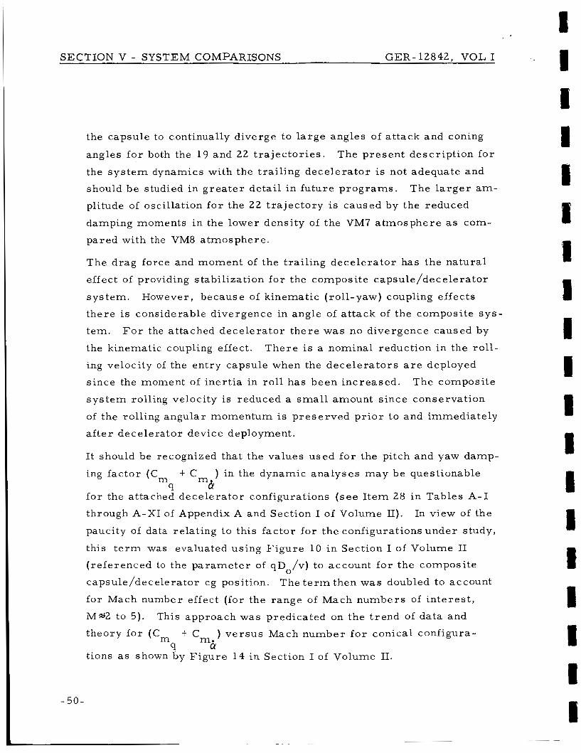
SECTION V - SYSTEM COMPARISONS GER-12842, VOL I
5 0 -
the capsule to continually diverge to l a rge angles of a t tack and coning
angles fo r both the 19 and 22 t r a j ec to r i e s .
the s y s t e m dynamics with the t ra i l ing dece lera tor is not adequate and
should be studied i n g r e a t e r detai l i n fu ture p rograms .
plitude of oscillation f o r the 2 2 t ra jec tory is caused by the reduced
damping moments i n the lower densi ty of the VM7 a tmosphere as com-
pared with the VM8 a tmosphere .
The p resen t descr ipt ion fo r
The l a r g e r am-
The drag force and moment of the t ra i l ing dece lera tor has the na tura l
effect of providing stabil ization f o r the composite capsule/decelerator
sys tem. However, because of kinematic ( rol l -yaw) coupling effects
there is considerable divergence in angle of a t tack of the composi te s y s -
tem.
the kinematic coupling effect.
ing velocity of the en t ry capsule when the dece le ra to r s a r e deployed
s ince the moment of iner t ia in ro l l has been inc reased .
s y s t e m rolling velocity is reduced a small amount s ince conservat ion
of the rolling angular momentum is p rese rved p r i o r to and immediately
a f t e r dece lera tor device deployment.
F o r the attached dece lera tor t he re was no divergence caused by
T h e r e is a nominal reduction in the ro l l -
The composi te
It should be recognized that the values used f o r the pitch and yaw damp-.
ing fac tor (C
fo r the attached dece lera tor configurations ( s e e I t e m 28 in Tables A- I
through A-XI of Appendix A and Section I of Volume II). paucity of data relating to this fac tor for the configurations under study,
this t e r m was evaluated using Figure 10 i n Section I of Volume I1
( re ferenced to the pa rame te r of qD /v) to account fo r the composi te
capsule/decelerator cg position.
f o r Mach number effect (for the range of Mach numbers of i n t e re s t ,
M*2 to 5).
theory f o r (Cm t C
tions a s shown by Figure 14 in Section I of Volume 11.
t Cm, ) in the dynamic ana lyses m a y be questionable m 9 CY
In view of the
0
The t e r m then was doubled to account
This approach was predicated on the t rend of da ta and
) v e r s u s Mach number f o r conical configura- m. 9 CY
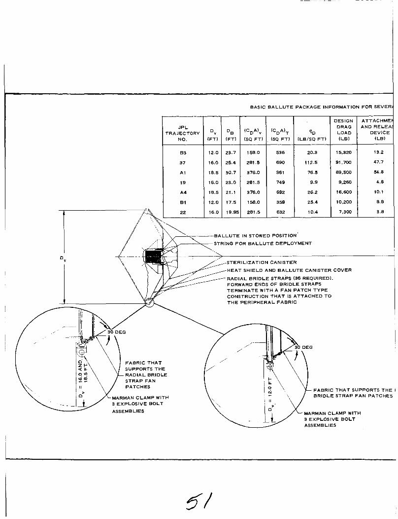
BASIC B A L L U T E PACKAGE INFORMATION FOR SEVEl
JPL TRAJECTORY
NO.
83
37
A1
19
A4
E 1
Dv (FT) (FT)
12.0 23.7
16.0 25.4
18.5 30.7
16.0 23.0
18.5 21.1
12.0 17.5
DV
(CDAlV
(SQ F T )
158.0
281.5
376.0
281.5
376.0
158.0
(CDA)T
(SQ FT)
536
690
96 1
749
692
359
9, (LB/SQ FT)
20.3
112.5
76.5
9.9
26.2
25.4
10.4
DESIGN DRAG LOAD ( L E )
ATTACHME AND RELEI
DEVICE (LE)
15,320
91,700
89,500
9,260
16,600
10,200
7,300
I 13.2
47.7 I 54.8
4.8
10.1
8.8
3.8
B A L L U T E IN STOWED POSITION
STRING FOR B A L L U T E DEPLOYMENT
T lON CANISTER
HEAT SHIELD AND B A L L U T E CANISTER COVER
RADIAL BRIDLE STRAPS (36 REQUIRED). FORWARD ENDS OF BRIDLE STRAPS TERMINATE WITH A F A N PATCH T Y P E CONSTRUCTION T H A T IS ATTACHED TO T H E PERIPHERAL FABRIC
FABRIC T H A T SUPPORTS T H E I BRIDLE STRAP F A N PATCHES
FABRIC T H A T SUPPORTS THE R A D I A L BRIDLE STRAP F A N PATCHES
MARMAN CLAMP WITH 3 EXPLOSIVE B O L T
ASSEMBLIES MARMAN CLAMP WITH
I
3 EXPLOSIVE BOLT ASSEMBLIES

SECTION V - SYSTEM COMPARISONS CER-12842, V O L I
4L CAPSULE DIAMETERS ( D v )
:: 1 AUX:I:RY EQUIPMENT FOR STOWING
12.9
106.1
108.3
5.6
18.6
1 13.3
7.4
B A L L U T E CANISTER AND HEAT SHIELD
(LB)
60
80
110
80
110
60
80
B A L L U T E DACRON FABRIC
(LB)
129.3
1061.0
1083.0
56.1
185.9
132.9
74.3
T O T A L PACKAGE CONCEPT
( L B )
215.4
1294.8
1356.1
146.5
324.6
215.0
165.5
INLET FOR RAM INFLATION (16)
,/" /'
A D l A L r
NOTE: UNLESS OTHERWISE SPECIFIED
1 . THE ATTACHMENT DETAILS SHOWN FOR Dv = 12.0 F T ARE FOR TRAJECTORY 83 ONLY
THE ATTACHMENT DETAILS SHOWN FORDv = 16.0 F T ARE FOR TRAJECTORY 37 ONLY
THE ATTACHMENT DETAILS SHOWN FOR Dv = 18.5 F T ARE FOR TRAJECTORY A1 ONLY
2.
3.
4. THE ATTACHMENT DETAILS ARE BASED ON THE USE OF 7075-T6 ALUMINUM UNDER LOAD A T 350 F WITH THE FOLLOWING VALUES:
Ft Y
Fbr
Fs
= 0.62 X 67,000 = 41,500 LB/SQ IN.
= 0.67 X 94,000 = 63,000 LB/SQ IN.
= 0.74 X 46,000 = 34,000 LB/SQ IN
Y
U
I Figure 23 - Trailing BALLUTE
-5%.
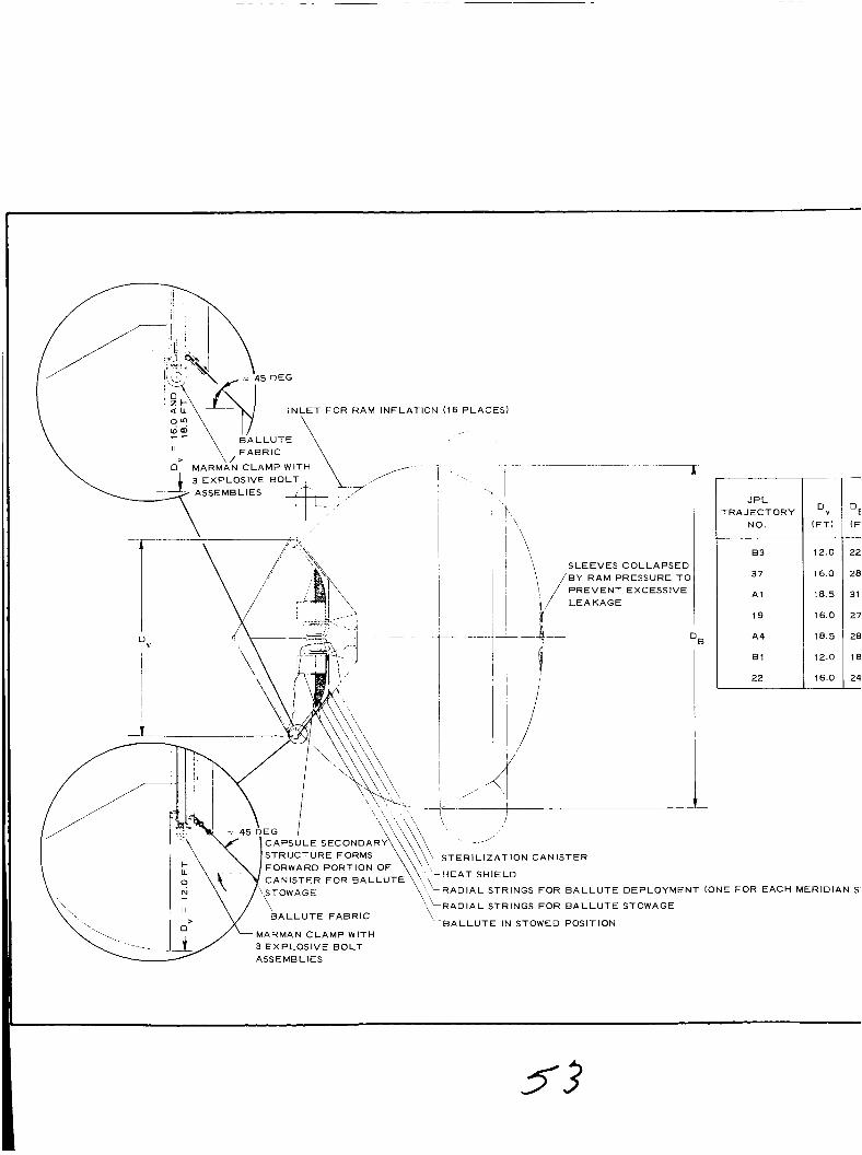
PLACES)
I I t MARMA’N CLAMP WITH 3 EXPLOSIVE BOLT ASSEMBLIES
I ‘-/ ’ \ \
SLEEVES COLLAPSED B Y RAM PRESSURE TO PREVENT EXCESSIVE LEAKAGE
T
/
J P L ‘RAJECTORY
NO.
8 3
37
A1
19
A4
B1
22
DEPLOYMENT(ONEF0REACH
STOWAGE
D” (FTI
12.0
16.0
18.5
16.0
18.5
12.0
16.0
DE (F
22
28
31
27
28
18
24 -
MERIDIAN S-

I SECTION V - S Y S T E M COMPARISONS GER-12842 , VOL I
DESIGN DRAG LOAD (LE)
15,330
90,500
89,400
9,260
14,900
10,200
7,310
-
3
7’ - .9
.O
.7
1
.6
.9
.9 -
ATTACHMENT AND RELEASE
DEVICE (LE)
13.9
56.9
65.6
5.8
10.9
9.2
4.6
BASIC BALLUTE PACKAGE INFORMATION FOR SEVERAL CAPSULE DIAMETERS (Dv)
(CDA)V
(SQ F T )
158.0
281.5
376.0
281.5
376.0
158.0
281.5
RAP)
536
796
1023
750
842
3 59
633
20.3
88.0
68.8
9.9
16.0
25.4
10.4
AUXILIARY BALLUTE BALLUTE
10.1
63.1
68.6
6.2
18.4
11.6
7.7
Fs = 0.74 X 46,000 = 34,000 LEI’S0 IN. h l
60
80
110
80
110
60
80
100.7
631 .O
686.0
61.9
183.5
116.3
77.0
NOTE: UNLESS OTHERWISE S PEClFlED
1 . THE ATTACHMENT DETAILS SHOWN FOR Dv = 12.0 F T ARE FOR TRAJECTORY 83 ONLY
THE ATTACHMENT DETAILS SHOWN FOR D V = 16.0 F T ARE FOR TRAJECTORY 37 ONLY
THE ATTACHMENT DETAILS SHOWN FOR Dv = 18.5 F T ARE FOR TRAJECTORY A1 ONLY
2.
3.
4. THE ATTACHMENT DETAILS ARE BASED ON THE USE OF 7075-T6 ALUMINUM UNDER LOAD A T 350 F WITH T H E FOLLOWING VALUES:
Ft Y
Fbr
= 0.62 X 67,000 = 41,500 LB/SQ IN.
= 0.67 X 94,000 = 63,000 L B / S Q IN. Y
TOTAL PACKAGE CONCEPT
(LE)
184.7
831 .O
930.2
153.9
322.8
197.1
169.3
Figure 2 4 - Attached B A L L U T E
- 54-
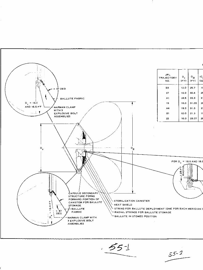
JPL TRAJECTORY
NO.
83
37
A 1
19
A4
E1
22
D" (FT)
12.0
16.0
18.5
16.0
18.5
12.0
16.0
(FT)
25.7
30.4
35.9
31.05
31.5
21.3
20.07
f 6 5 -1

1 SECTION V - SYSTEM COMPARISONS GER-12842, VOL I
3ASlC B A L L U T E PACKAGE INFORMATION FOR SEVERAL CAPSULE DIAMETERS (Dv)
,A)V > F T ) - 58.0
31.5
76.0
11.5
76.0
58.0
31.5
536
735
1005
749
800
3 59
633
20.3
103.0
72.15
9.9
17.5
25.4
10.4
DESIGN DRAG LOAD ( L B )
15,400
93,300
90,900
9,260
14,820
10,200
7,310
z--\ FOR D v = 12.0 FT
~
ATTACHMENT AND RELEASE
DEVICE ( L E )
13.4
51 .8
57.7
5.1
9.4
8.9
4.1
AUXILIARY EQUIPMENT
FOR STOWING ( L E )
4.3
35.1
36.3
2.9
6.6
5.9
3.7
B A L L U T E CANISTER AND HEAT SHEILD
(LB)
60
80
110
80
110
60
80
B A L L U T E DACRON FABRIC
( L B )
42.6
351 .O
363.0
29.4
65.6
58.8
36.9
T O T A L PACKAGE CONCEPT
120.3
51 7.9
567.0
117.4
191.6
133.6
124.7
B A L L U T E B A L L U T E FABRIC FABRIC
\ HARMAN CLAMP W I T MARMAN CLAMP WITH
9
NOTE: UNLESS OTHERWISE SPECIFIED
1. T H E ATTACHMENT DETAILS SHOWN FOR Dv = 12.0 FT ARE FOR TRAJECTORY 83 ONLY
2. T H E ATTACHMENT DETAILS SHOWN FOR Dv = 16.0 F T ARE FORTRAJECTORY 37 ONLY
3. T H E ATTACHMENT DETAILS SHOWN FOR Dv = 18.5 F T ARE FOR TRAJECTORY A 1 ONLY
3 EXPLOSIVE B O L T 4SSEMB LIES
TRAP)
3 EXPLOSIVE B O L T ASSEMBLIES
4. T H E ATTACHMENT DETAILS AREBASED ON T H E USE O F 7075-T6 ALUMINUM UNDER LOAD A T 350 F WITH T H E FOLLOWING VALUES:
Ft Y
Fbr
FB
= 0.62 X 67,000 = 41,500 LB/SQ IN.
= 0.67 X 94,000 = 63,000 LB/SQ IN. Y
= 0.74 X 46,000 = 34,000 LB/SQ IN. U
Figure 25 - Tucked-Back BALLUTE
- 56

BASIC ATTACHED 12
J P L rRAJECTORY
NO.
8 3
37
A1
19
A4
61
22
12.0
16.0
18.5
16.0
18.5
12.0
16.0
-
( 5 ISC -
E
E
6
i
E
3
E -
-CAPSULE SECONDARY STRUCTURE SUPPO CANISTER FOR AIRMAT CONE STOWAGE
FABRIC ATTACHMENT SKIRT
AIRMAT CONE IN DEPLOYED POSITION I I”
MARMAN CALMP WITH 3 EXPLOSIVE BOLT ASSEMBLIES
I
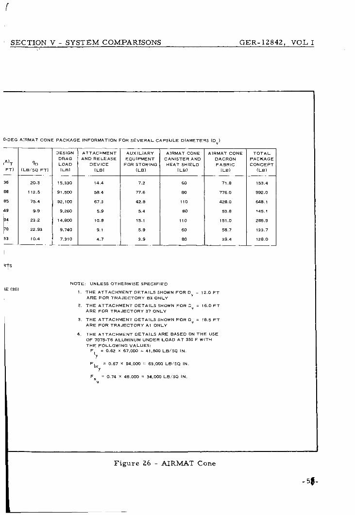
SECTION V - S Y S T E M COMPARISONS C E R - 1 2 8 4 2 , VOL I
(LB/SQ FT)
20.3
112.5
75.4
9.9
23.2
22.93
10.4
0-DEG AIRMAT CONE PACKAGE INFORMATION FOR SEVERAL CAPSULE DIAMETERS (Dv)
DESIGN DRAG LOAD (LB)
15,330
91,500
92,100
9,260
14,800
9,740
7,310
36
88
85
149
‘i I
i t s
IE (36)
ATTACHMENT AND RELEASE
DEVICE (LB)
14.4
58.4
67.3
5.9
10.8
9.1
4.7
AUXILIARY EQUIPMENT
FOR STOWING ( L e )
7.2
77.6
42.8
5.4
15.1
5.9
3.9
AIRMAT CONE CANISTER AND HEAT SHIELD
(LB)
60
80
110
80
110
60
80
AIRMAT CONE DACRON FABRIC
(LB)
71.8
776.0
428.0
53.8
151 .O
58.7
39.4
NOTE: UNLESS OTHERWISE SPECIFIED
1 . THE ATTACHMENT DETAILS SHOWN FOR D v = 12.0 FT ARE FOR TRAJECTORY 83 ONLY
2. THE ATTACHMENT DETAILS SHOWN FOR DV = 16.0 FT ARE FOR TRAJECTORY 37 ONLY
3. THE ATTACHMENT DETAILS SHOWN FOR Dv = 18.5 FT ARE FOR TRAJECTORY A1 ONLY
4. THE ATTACHMENT DETAILS ARE BASED ON THE USE OF 7075-T6 ALUMINUM UNDER LOAD A T 350 F WITH THE FOLLOWING VALUES:
Ft Y
Fbr
Fs
= 0.62 X 67,000 = 41,500 LB/SQ IN.
= 0.67 X 94,000 = 63,000 LB/SQ IN. Y
= 0.74 X 46,000 = 34,000 LB/SQ I N U
T O T A L PACKAGE CONCEPT
( L B )
153.4
992.0
648.1
145.1
286.9
133.7
128.0

T R A I L I NG B A L L U T E P I T C H YAW D A M P I N G -0 .29
; ARE I N A C C U R A T E ! I I,P A N D 8
A T T A C H E D B A L L U T E P I T C H YAW D A M P I N G -0 .270
h
m 0
X
I-
c
: 10 LL v
w 0 3 I-
I- 1 U
-
0 50 100
U
,g
- ---p
150 T O T A L A N G L E ( D E G R E E S )
4c
- 30
20
h
m 0 c
X
I- : 1 0 LL v
W 0 3 I-
I- _J
-
4 0
T U C K E D - B A C K B A L L U T E P I T C H YAW D A M P I N G -0.336
40r
SECTION V - SYSTEM COMPARISONS GER-12842, VOL I 8 I I 1 I 1 I i 1 I I I I I I I I
---! j__ 0
ANGULAR R A T E S ( R A D I ANS P E R SECOND)
-0 .6 0 0 . 6
1 I I i N O T E :
ARROW I NO I C A T E S D E P L O Y M E N T A L T 1 T U D E
1
T O T A L A N G L E A N G U L A R R A T E S ( D E G R E E S ) ( R A D I A N S P E R S E C O N D )
h
m 0 c
X
I- W W
LL v
W 0 3 I-
c -I a
-
T O T A L A N G l ( D E G R E E S )
4c
- 3c
2c
h
m 0 c
X
c t: 1 c LL v
W 0 3 I-
I- 1
-
u c
- 0 . 6 ANGULAF ( R A D I A \
A I R M A T CONE
0 .6 1 ! A T E S P E R S E C O N D )
P I T C H YAW D A M P I N G -0 .280
2 4 6 T O T A L ANG ( D E G R E E S )
4c
- 3c
20
h
m 0
x I-
c
: 10 LL v
W 0 3 I-
I- _1
-
u o - [
AN
~, L A R 0 .6 1 .0
l A T E S ( R A D I A N S P E R SECOND)
Figure 27 - Decelera tor Oscillation Charac te r i s t ics (Atmosphere VM8; Tra jec tory 19)
- 59-

SECTION V - SYSTEM COMPARISONS GER-12842, VOL I
T R A I L I NG B A L L U T E *
T U C K E D - B A C K B A L L U T E P I T C H YAW D A M P I N G = -0.258
70
60
50 n 0 o 40 r
x t- 30
- 20
W W LL
W 0
E l 0
2 4 6 T O T A L A N G L ( D E G R E E S )
E A N G U L A R R A T E S
A T T A C H E D B A L L U T E P I T C H Y A W D A M P I N G = - 0 . 2 0 8
70 70
60 60
50 50 n 0
n
o 40 0 c
o 40 r
x x k 30 L 30
20 '20 W LL
W W
W 0
W 0
2 1 0 210 - - k 1 I-
-I 4 0 a
0 2 4 6 8 -0.6 0 0.6 1 T O T A L A N G L E A N G U L A R R A T E S
( R A D I A N S P E R S E C O N D ) ( D E G R E E S ) ( R A D I A N S P E R S E C O N D )
70
60
50 n ? 40
x L 30
'20 W lA.
W 0
El0 b- 1 4 0 -0.6 0 0.6
( R A D I A N S P E R S E C O N D )
!
8 . o
N O T E : ARROW I NO I C A T E S D E P L O Y M E N T A L T I T U D E
A I R M A T C O N E
3
P I T C H Y A W D A M P I N G -0.218 70
60
50 h
m 0 40 r
x 30
- 20
W LL
W 0
E l 0 k 1 4 O
0 2 4 6 8 -0.6 0 0.6 1.0 T O T A L A N G L E A N G U L A R R A T E S ( D E G R E E S ) ( R A D I A N S P E R S E C O N D )
-
Figure 28 - Decelerator Oscil lation Charac t e r i s t i c s (Atmosphere VM7; Trajectory 22)
-60 -

SECTION V - SYSTEM COMPARISONS GER-12842, VOL I
3 . COMPARISONS O F COMPOSITE SYSTEMS
a . Gene ra l - The final compar ison of the expandable dece le ra to r cha rac t e r i s t i c s
was made p r imar i ly in t e r m s of engineering design considerat ions.
In o ther words s ince a l l the configurations init ially w e r e "s ized" to
a t ta in specified t a rge t Mach number/alt i tude conditions ( s e e Appen-
dix B ) , the compar ison was made on the bas i s of the 17 cha rac t e r -
i s t i c s Table IV shows the r e su l t s of this compar ison .
Dacron was used f o r the envelope fabr ic of all the dece le ra to r s . The
r e su l t s fo r the var ious charac te r i s t ics in Table I V a r e d i scussed below.
inTab le IV.
- b. I tems 1 and 2 - Decelerator Diameter and Altitude a t Mach Number 1
The dece le ra to r diameter was de te rmined by the f i r s t approximation
analysis procedure descr ibed in Section V of Volume I1 and i l lus-
t ra ted in F igure 1 0 of t h i s volume.
e r a t o r s i z e w e r e selected as corresponding with o r tending toward
the minimum weight fraction fo r the dece le ra to r device that would
achieve a ta rge t point Mach number of about one n e a r a t a rge t a l t i -
tude of 20, 000 f t for the A l , B3 and 1 9 en t ry cases and a t a rge t a l t i -
tude near 30, 000 ft fo r the 2 2 en t ry case . The values w e r e obtained
f r o m Figures 6 7 , 68, 69 , 7 0 , 73 , 74 , 87 and 88 insec t ion VIof Vol-
ume 11.
tor ies a r e the identical designs f o r the 2 2 and 19 t r a j ec to r i e s , r e -
spect ively.
var ia t ion on s y s t e m per formance and engineering design cons idera-
t ions.
The numer ica l values of decel-
Note that the dece lera tor s i zes f o r the 23 and 30 t r a j ec -
The purpose was to a s s e s s the effect of a tmosphere
Also note that the dece lera tor s i z e s es tabl ished on the bas i s of the
f i r s t approximation analysis procedure was reasonably accu ra t e for
the A1 and B3 ent ry cases to achieve a t a rge t Machnumber ofabout
one n e a r 20,000 ft .
F o r the 19 t r a j ec to ry with a t a rge t alt i tude near 2 0 , 000 ft and 2 2
-61-
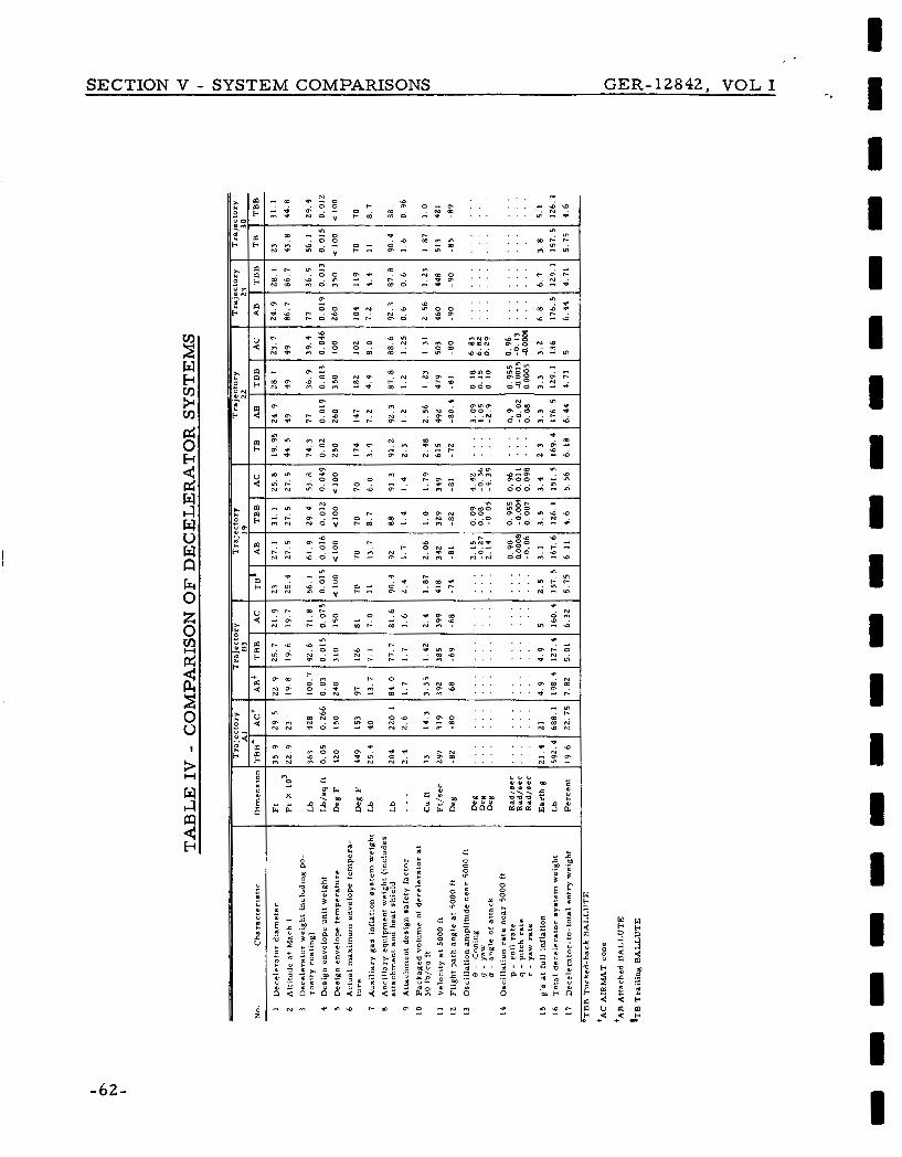
SECTION V - SYSTEM COMPARISONS GER-12842, VOL I
- 6 2 -
a b ;
N - w d - 0 . . . . .n i i . o o h P 0 - 0 . . . . . - * : o ; E m 2 0 - 2 : . . . .
- . . - Q Q
A N ,
. . . . . . Y) C I Q P C - . . Z o e - . a m o o _ . . _ . . m i 3 . . . . . . . C
a - . n : % K O ; 0 ; g o N $ ?
m . . . . . C N c a .n- . o o a - . C d m m . . . . . . e.&: d e N - y o ; , 2 ; 6 ; -4: . . . . . . , 2 . ;
1 1 1 I 1 I I 1 1 I I 1 1 I 8 I I I I
SECTION V - SYSTEM COMPARISONS GER-12842, VOL I
t r a j ec to rywi th a ta rge t a l t i tude of 3 0 , 000 f t , the procedure was con-
serva t ive . Consequently i t can be expected that sl ightly s m a l l e r dece l -
e r a t o r s i zes could be employed to achieve the specified t a rge t con-
ditions fo r these en t ry cases with a s m a l l amount ofweight saving.
- c . I tems 3 and 4 - Decelera tor Weight and Envelope Weight
As d iscussed insec t ion 111, I tem 1 useful integrated t radeoffs can be
made between dece lera tor and total weight in t e r m s of Mach number
and al t i tude a t deployment, dece le ra to r s i ze , per formance effective-
ness , a n d m a t e r i a l cha rac t e r i s t i c s . The formulat ion of the t radeoffs
for the specif ic dece le ra to r s is es tab l i shed in AppendixA of Volume 11.
Note that the weight/strength ana lys i s of Appendix A, Volume I1
a s s u m e s that the dece lera tor m a t e r i a l s w e r e operating a t a s t a t i c
elevated design t empera tu re . In the c a s e of dacron this t empera -
t u re leve l was taken a s 350 F where the s t rength is nominally one
half the value compared to room t e m p e r a t u r e o r about 70 F.
t ionally, a des ign safety fac tor of 2. 0 i s ref lected in the weight/
s t rength ana lys i s .
ing t empera tu re i s considered as a p rac t i ca l design point for in-
f la table s t r u c t u r e s fabr icated of flexible m a t e r i a l s .
Addi-
A half- s t rength operat ing leve l with cor respond-
On the bas i s of the above considerat ions, a f i r s t approximation
weight was es tab l i shedfor the dece le ra to r s i z e s corresponding with
I tem 1 of Table IV (see I t em 6 of Tables A - I through A-XI in Ap-
pendix A). Using these va lues , the proport ion of weight a l located
to the dece le ra to r envelope was de te rmined . Then using the the r -
mal ana lys i s procedures of Section IV of Volume 11, a second ap -
proximation was made to s e c u r e a m o r e l ikely value fo r the opera-
ting t e m p e r a t u r e (Item 5) and unit weight of the dece le ra to r enve-
lope (I tem 4).
through 50 of Volume I1 and I tem 9 of Tables A - I through A-XI of
Appendix A.
includes a unit coating weight of a t l ea s t 0. 01 lb/sq ft to provide a
The values de te rmined a r e shown in F igu res 46
Note that for all c a s e s the dece le ra to r envelope weight
- 6 3 -
low value of poros i ty for the envelope . t e rna l p re s su r i zed gas leakage to no g r e a t e r than 0. 02 lb/sq f t /sec.
The coating l imi t s the in-
In re i te ra t ion the s t rength and the re fo re the weight of the mer id ian
cables f o r a l l the dece le ra to r s and the r i s e r l ine of the t ra i l ing
BALLUTE is based on the half s t rength of dac ron m a t e r i a l with a
design safety fac tor of 2 . 0. The weights fo r I tem 3 in this Table
a r e based on the above considerat ions.
- d. I tems 5 and 6 - Design and Actual Maximum Dece le ra to r Envelope Tempera tu re
In comparing I tems 5 and 6 , note that the second approximation fo r
the a s sumed operat ing t empera tu re f o r the dac ron dece le ra to r en-
velope was quite a c c u r a t e f o r the A1 and 19 t r a j ec to r i e s and for the
AIRMAT cone in the 2 2 t r a j ec to ry .
second approximation was s t i l l conserva t ive by as much as a f ac to r
of 1 . 5 to 2 . 5. However as noted above ( s e e Item 4) the d e c e l e r a t o r
unit weight includes a minimum coating of a t least 0 . 01 lb/sq f t .
F o r the o the r t r a j e c t o r i e s the
Thus with the possible exception of the a t tached BALLUTE fo r the
B3 t ra jec tory w h e r e a 10 percent saving in dece le ra to r weight might
be real ized, only nominal weight would be saved for the o ther c a s e s .
A l so as noted above the m e r i d i a n cable and r i s e r - l i n e s t r eng th and
weight would co r re spond approximate ly to a n operat ing t e m p e r a t u r e
of 350 F with a design safety fac tor of 2 . Consider ing the 19 and 30
t r a j ec to r i e s ,where the operat ing t e m p e r a t u r e is equivalent to r o o m
t empera tu re , the dece le ra to r m e r i d i a n cables and r i s e r s ac tua l ly
would have a design safe ty fac tor of about 4 based on the weights of
I tem 3 .
and 23 t r a j ec to r i e s would range between about 3 . 2 and 3 . 8 f o r the
indicated va lues of operat ing t e m p e r a t u r e .
The design safe ty f ac to r s cor responding with the B3 , 22
- e . I tem 7 - Auxil iary Gas Inflation S y s t e m Weight
F o r the r a m - a i r inflated d e c e l e r a t o r s , th i s i t e m m a y be cons idered
I I I 1 I 1 1 1 I 1 I 1 1 I I I I
SECTION V - SYSTEM COMPARISONS GER-12842, VOL I -,

SECTION V - SYSTEM COMPARISONS GER-12842, VOL I
as optional. By the definition of this study, however, i t is manda-
to ry with the 120-deg AIRMAT cone.
flation aid gas f o r the r a m - a i r inflated configurations was approxi-
mated as 50 percent of that required for the fully inflated decel-
e r a t o r a t the design initial deployment Mach number , a l t i tude, and
in t e rna l p r e s s u r e corresponding to the p r e s s u r e recovery a t the
ram-air inlets of the decelerator .
factor of 1. 5 to account f o r the container weight ( s e e I tem 12 of
Table A - I through A-XI i n Appendix A ) . F o r the AIRMAT cone the
inflation gas and container weight was determined f r o m Figure 100
in Section VI1 of Volume I1 corresponding to the s i z e and supporting
p r e s s u r e requi rements encountered a t the init ial deployment Mach
number and altitude for this configuration.
The weight of auxi l iary in-
This value was multiplied by a
- f . I tems 8 , 9 and 10 - Ancillary Equipment Weight, Attachment Design Safety Factor ,and Packaging Volume
I tem 8 includes the weight es t imates for the dece lera tor attach-
men t s , packaging equipment, separat ion and deployment means ,
and base heat shield.
ment and separat ion means a r e provided fo r each of the dece le ra to r s
considered in this study.
Figures 23 through 26 i l l u s t r a t e how at tach-
Note that the anci l lary equipment weight includes the capsule b a s e
heat shield to protect the dece lera tor and equipment f r o m the b a s e
heating encountered during en t ry . The shield probably will be fab-
r icated of f iberglass with a thickness capable of maintaining the
in t e rna l t empera tu re below 200 F for a total heat input load of
about 1000 B T U ' s / s q f t . On the bas i s of M a r s en t ry energy levels
and typical base heating levels encountered in orb i ta l e n t r y of blunt
body shapes , this heat input is considered r ea l i s t i c . The weight
of the heat shield allows fo r additional reinforcing to support the
base p r e s s u r e and deceleration loads of en t ry .
function of the heat shield would be utilized to ex t r ac t and deploy
the dece lera tor .
The separa t ion
-65-

SECTION V - SYSTEM COMPARISONS GER-l2842A, VOL I
I t em 9 indicates the a t tachment design fac tor .
spond with the load developed a t full inflation of the d e c e l e r a t o r s
and the design yield s t r e s s f o r the attachment components a r e in-
dicated in F igu res 23 through 26.
conservat ively designed by assuming operat ion a t a n elevated t em-
pe ra tu re of 350 F and the m a t e r i a l s t r e s s capabili ty cor responding
to this t empera tu re level was used.
The values c o r r e -
The attachment suppor ts a r e
The packaging volume indicated by I t em 10 f o r the d e c e l e r a t o r s is
referenced to a packaging densi ty of 30 lb/cu f t , which is a typical
value for expandable dece le ra to r s fabr ica ted of flexible m a t e r i a l .
Even i f the packaging densi ty w e r e reduced to 20 lb/cu f t , the vol-
ume requi rements a r e not excess ive in t e r m s of the volume ava i la
bil i ty provided i n this study.
g. I t em 11 - Composite Sys tem Velocity a t 5, 000 f t .above T e r r a i n
The tabulated data for this i t e m and the space - t ime h is tor ies of
F igu res B-1 through B-6 in Appendix B show that reasonably low
subsonic velocit ies will be attained s o that conventional parachute
s y s t e m s could be deployed to l imit t e r r a i n impact veloci t ies to
acceptable leve ls .
1 established on the bas i s of achieving a t a rge t point Mach number
of about one n e a r o r above a n alt i tude of 20,000 ft in the VM8 a tmo-
s p h e r e and 3 0 , 0 0 0 ft in the VM7 a tmosphere .
This finding is f o r the dece le ra to r s i z e s of I t em
- h. I tem 12 - Composite Sys tem Fl ight -Pa th Angle a t 5, 000 ft above T e r r a i n
The attached expandable dece le ra to r s can def lec t the e n t r y capsule
flight-path fo r the A I , 19, 2 2 , 23 and 30 e n t r y c a s e s to within 10
deg of the ver t ica l at a n al t i tude of 5000 f t .
be compatible with the levels of subsonic veloci t ies of I t em 11 and
the energy and control capabili t ies of a sof t - landing, t e rmina l -
s t age , r e t rosys t em of the Surveyor type.
This def lect ion would
-66- Revised 21 October 1966

SECTION V - SYSTEM COMPARISONS G E R - 12842A, VOL I
- i. Item 13 and 14 - OscillationAmplitudes a n d R a t e s a t 5000-ftAltitude
AS descr ibed previously, for the case of the t ra i l ing dece le ra to r s
there is a divergence tendency in angle of a t tack resul t ing p r imar i ly
f r o m the inadequate descr ipt ion of the 8-degree-of - f reedom com-
puter formulat ion ( see F igures 27 and 28 and Appendix C.) Limited
experience with the application of t ra i l ing dece lera tors attached to
a spinning forebody generally has not exhibited this tendency, a t
l ea s t to the magnitude encountered in this study.
the analytical (mathematical) descr ipt ion of the s y s t e m dynamics
should be studied and evaluated in much g r e a t e r detai l in future pro-
g r a m s fo r the application of t ra i l ing dece le ra to r s .
motion involving the use of the attached dece le ra to r s did not resu l t
in a l a rge angular divergence.
discussion of the dynamic analysis considerations and resu l t s .
Comparing the magnitudes of oscil lation amplitude and r a t e for the
corresponding decelerator configurations, the effect of a tmosphe r i c
density is apparent . The reduced damping moments in all modes of
oscil lation f o r t ra jectory 22 r e su l t - in l a r g e r values of angular am-
plitude and r a t e .
dicates that the attached configurations provide be t te r stabil i ty than
the t ra i l ing decelerator f o r the reason previously discussed.
bes t of the attached configurations is the tucked-back BALLUTE;
p r imar i ly because of higher and m o r e favorable values fo r C
X /Dv and (Cm t Cm.). See I tems 26, 27, and 28 in Tables
A-I11 and A-XI in Appendix A.
It is apparent that
The s y s t e m
See Appendix C f o r a comprehensive
The compar ison of the sepa ra t e dece le ra to r s in-
The
, Nci!
9 cy CP
I tem 15 - Maximum Operating g-Level
The decelerat ion g-levels encountered a t full inflation of the decel-
e r a t o r s a r e not excessive in re la t ion to those in ea r th en t ry ap-
plications.
than the peak loads a t launch and boost in the entry of the basic
capsule fo r the t ra jec tor ies s tudies .
Except for t r a j ec to ry A l , the load levels would be l e s s
Revised 21 October 1966 -67-

SECTION V - SYSTEM COMPARISONS GER- 12842A, VOL I .*
k. -
-68-
As i n Item 1, the dece le ra to r s fo r t r a j ec to r i e s 23 and 30 a r e the
same designs for t r a j ec to r i e s 2 2 and 19, respect ively. The c o r -
responding g-loads at full inflation of the dece le ra to r s for t r a j ec -
t o r i e s 23 and 30 a r e 2 and 1. 5 t imes g r e a t e r than the 2 2 and 19
c a s e s . Refering back to I t em 9 (Attachment Design) , the at tach-
men t design f o r both configurations in t r a j ec to ry 23 and f o r the
tucked-back BALLUTE in t r a j ec to ry 30 would not be adequate . Some
s t ruc tu ra l strengthening of the at tachments would be r equ i r ed with
nominal i n c r e a s e in the dece le ra to r a t tachment weight.
however, that the a t tachment design is conservat ive on the bas i s of
the a s sumed elevated operat ing t empera tu re .
the effects of the s y s t e m dynamics on the dece le ra to r s t r eng th and
weight.
I tems 16 and 17 - Total Dece le ra to r Sys t em Weight and Weight F rac t ion -
I tem 16 is the s u m of I t ems 3 , 7, and 8 and I tem 17 is the percent -
a g e of the total dece le ra to r weight to the total en t ry capsule weight.
The tucked-back BALLUTE has the m o r e favorable weight f rac t ion
by a slight m a r g i n ove r the AIRMAT cone, which is the next bes t
configuration.
among al l configurations does not exceed two pe rcen t of the total
en t ry capsule weight, much l e s s than the a c c u r a c y of the a s s u m p -
tions and approximations made in the p a r a m e t r i c ana lyses of this
s tudy .
Recal l ,
Appendix C cons iders
F o r t r a j ec to r i e s 19 and 2 2 the weight difference
F a c t o r s other than weight and pe r fo rmance wi l l be impor tan t i n
choosing the m o s t sui table expandable t e r m i n a l d e c e l e r a t o r fo r a
M a r s lander sys t em. These f a c t o r s would include s t a t i c and dy-
namic aerodynamic s tabi l i ty , complexi ty and cos t of fabr icat ion
methods, sequencing and cont ro l functions, i n t e r f ace cons t ra in ts ,
e t c .
a m o r e comprehensive and detai led s y s t e m des ign than encom-
passed by this s tudy ( s e e next sec t ion) .
The accu ra t e evaluation of t hese f a c t o r s only can be m a d e by
Revised 2 1 October 1966
1 ‘ 1 -. 1 8 I 1 I I 1 1 I I 1 I I I 1 I D
GER-12842. VOL I
SECTION V I - RECOMMENDATIONS
As in fe r r ed f r o m the s ta tement of work fo r this p r o g r a m , this study was
not expected to yield data in sufficient detai l f o r complete and final engineer-
ing designs of expandable dece lera tors for M a r s a tmosphe re entry. Conse-
quently recommendat ions w e r e made f o r a r e a s requir ing additional investi-
gation and analyses . Additionally descr ipt ions of development, simulation,
and proof- t e s t p rocedures to qualify aerodynamic dece lera tor s y s t e m s for
the M a r s miss ion , including the types of fac i l i t i es required, w e r e made
( see Sections VIII, IX, and X of Volume 11).
The a r e a s recommended a s requiring additional investigation include:
1. Detailed configuration design analyses fo r a n at tached
expandable decelerator assoc ia ted with a specific en t ry
capsule and per formance envelope within the broad
l imits encompassed by this study
2. Fabricat ion techniques and constraints for a n approxi-
mate ly full- sca l e , ram-a i r - inf la ted attached expandable
configuration
3 . Conventional wind-tunnel and free-f l ight wind- tunnel
model t e s t s to determine the aerodynamic pe r fo rmance
and stabil i ty of an en t ry capsule/attached expandable
configuration under s imulated operating environments
( see Section VIII of Volume 11)
4. Design and fabrication of a full- o r near - fu l l - sca le
functional mockup of a n en t ry capsule/attached expand-
able configuration for packaging, deployment, and in-
flation t e s t s in the NASA Ames o r Langley fu l l - sca le ,
wind- tunnel facil i t ies
-69-

5. Large-sca le , f ree- f l igh t s imulat ion t e s t s of a n en t ry
v e hic 1 e /a tt a c he d expandable c onf igu r a t i on us i ng r o c ke t
boost techniques
Section IX of Volume 11)
as i l lus t ra ted by F igu re 2 9 ( s e e
6. Functional, environmental , s te r i l i za t ion and rel iabi l i ty
tes ts of m a t e r i a l s hardware , and anc i l l a ry equipment
assoc ia ted with the en t ry capsule/attached expandable
c onf igu r a t i on
1 1 8 1 1 1 1 1 1 1 1 1 1 1 1 1 1 I
GER-12842 , VOL I SECTION VI - RECOMMENDATIONS

/ DE-SPIN J E T S q, 1S0,OOO FT
a'/; M A C H 5.0 A D D P E P DRAG BRAKES OR
A D D P E P R E T R O ROCKETS \ / Q C O N E D E P L O Y E D
NOSE C O N E O F F
C-BAND TRANSPONDER 225-MC T R A N S M I T T E R
SPIN R A T E 3000 LB MAX
V E H I C L E
C O N D OR T H I R D AGE D E P E N D I N G
N F I G U R A T I O N
L A U N C H
B E A C O N T R A N S P O N D E R ON F IRST S T A G E IGNIT ION T R A C K I N G F L A R E S T E L E M E T R Y ON S E Q U E N C E R O N
S T A T I C PRESSURE D Y N A M I C PRESSURE DE c E LE RAT OR SHOCK D E C E L E R A T O R DRAG A C C E L E R A T I O N T E MPE R A T URES B A L L U T E I N T E R N A L PRESSURE F M / F M P A M E V E N T MONITORING
I N - F L I G H T ( E L E C T R O M E C H A N I C A L T IMER) - AI
L A S T STAGE BOOSTER I G N I T I O N L A S T S T A G E BOOSTER SEPARATION, D R A l T E L E M E T R Y C A L I B R A T E
DE-SPIN JETS ( R A T E GYRO) ON-BOARD CAMERAS (2) S T A T I C A N D DYNAMIC PRESSURE PORTS C C A N I S T E R E J E C T I O N
D A T A TRANSMISSION - A D D P E P T E L E M E T R Y

SECTION VI - RECOMMENDATIONS GER-12842, VOL I
) D P E P PROGRAMMING
; BRAKES
P E N
D E C E L E R AT I ON C A N I S T E R 0 F F ’, B A L L U T E D E P L O Y E D
\ D E P LOY E D
WATER OR L A N D I M P A C T
PARA B A L L U T E F L O T A T I O N 240-MC B E A C O N FLASHING L I G H T D Y E MARKER 37-KC MARKER
F i g u r e 2 9 - Rocket Boost Technique for Simulation Tes t
- 72+
GER-12842, VOL I
SECTION VI1 - CONCLUSIONS
The r e s e a r c h conducted during this study has led to the following conclusions:
1. The suitable application of expandable t e rmina l decel-
e r a t o r s f o r M a r s a tmosphere en t ry can be establ ished
by the analyt ical formulation of environmental fac tors
and effects governing engineering applications and
s t ra ight forward engineering techniques of analysis and
design.
2 . Definitive t rends toward minimum weight f ract ions (of
reasonable magnitude) for expandable t e rmina l decel-
e r a t o r s with corresponding optimum values for init ial
operating Mach number (that i s , dynamic p r e s s u r e ) to
aerodynamical ly re ta rd en t ry capsules to Mach num-
b e r s of less than 1 . 0 a t alt i tudes of 2 0 , 0 0 0 and 30,000 ft
above M a r s for specific model a tmosphe res has been
establ ished. F o r all the en t ry c a s e s considered in this
study, the suitable applications fo r expandable t e rmina l
dece le ra to r s fo r Mars a tmosphe re e n t r y a r e within the
cu r ren t de c e 1 e r a t or techno logy.
3 . Dacron and Nomex, which a r e compatible with plane-
t a r y s te r i l i za t ion requirements , can be employed safely
for fabr icat ion of expandable t e rmina l dece le ra to r s
under the combined aerodynamic and t h e r m a l loading
environments encountered in M a r s en t ry for the t r a j ec -
to r ies considered in the study. F o r all c a s e s analyzed
minimum coating thickness of the o r d e r of 0. 01 lb/sq ft
can be employed to maintain low acceptable values of
- 7 3 -

SECTION VI1 - CONCLUSIONS GER-l2842A, VOL I
porosity f o r the dece lera tor envelope and to maintain
the ma te r i a l t empera ture to acceptable design values
with only minimum weight penalt ies.
4. The effect of varying t a rge t point Mach number f r o m
a nominal value of 1. 0 a t a specified t a rge t altitude has
a measurable effect on dece lera tor s i z e and weight
fraction.
5. Detailed engineering analysis , design, and simulation
testing pointed toward a specific expandable dece lera tor
configuration and performance envelope within the broad
range of values and t rends encompassed by this study
can be undertaken confidently.
implemented over a reasonable period of 24 months f r o m
go-ahead and r e s u l t in a prototype expandable decel-
e r a to r sys t em that could be flight-qualified subsequently
f o r a s e a r l y as the 1973 M a r s lander miss ion ( s e e
Section X of Volume 11).
estimated ( s e e Appendix D) that a p r o g r a m f o r the de-
sign, development, and t e s t of a n expandable te rmina l
aerodynamic dece lera tor fo r a M a r s lander capsule
could be accomplished a t an overa l l cost to the govern-
ment of l e s s than $ 3 million.
Such a p r o g r a m could be
F o r budgetary purposes i t was
- 74- Revised 2 1 October 1966

GER-12842, VOL J
LIST O F REFERENCES
1.
2.
3 .
4.
5.
6 .
7 .
8.
9.
AEDC TR-65-218: Drag Charac te r i s t ics of T h r e e BALLUTE Decel- e r a t o r s in the Wake of the ALARR Payload a t Mach Numbers 2 to 4. Arnold A i r F o r c e Station, Tenn. Arnold Engineering Development Center . 1965.
AEDC TDR-63- 11 9: Pe r fo rmance of Flexible Aerodynamic Dece le ra to r s at Mach Numbers f r o m 1. 5 to 6. Arnold A i r Station, Tenn. Arnold Engineering Development Center . 1963.
Alexander , W. C. : Investigation to Determine the Feasibi l i ty of Using Inflatable Balloon Type Drag Devices f o r Recovery Applications i n the Transonic , Supersonic , and Hypersonic Fl ight Regime. Part 11. Mach 4 to Mach 10 Feasibi l i ty Investigation. Akron, 0hio.Goodyear A i r c r a f t Corp. ASD TDR-62-702. December 1965.
Charczenko, N. : Aerodynamic Charac t e r i s t i c s of Towed Spheres , Coni- c a l Rings and Cones Used as Dece le ra to r s at Mach Numbers f r o m 1. 57 to 4 .65. TN D-1789. NASA, Apr i l 1963.
Charczenko. N. : and McShera. J. T. : Aerodvnamic Charac t e r i s t i c s of Towed Cones Used as Decelera tors a t Mach Numbers f r o m 1 . 5 7 to 4 .65. TN D-994. NASA, December 1965.
Altgelt , R. : Gemini BALLUTE Sys tem Development. GER- 11538 Akron, Ohio. Goodyear Aerospace Corporat ion. January 1965.
GER- 11665: Aerodynamic Deployable Dece le ra to r Pe r fo rmance Evalua- tion P r o g r a m . Akron, Ohio. Goodyear Aerospace Corporat ion.
AEDC-TR-65-266: The Charac te r i s t i c s of a BALLUTE in the Wake of the Mar t in Ful l sca le SV-5D Vehicle a t Mach Numbers from 0 . 6 to 2. 9. Arnold A i r Station, Tenn. Arnold Engineering Development Center . 1965.
AEDC-TR-64- 13 1: Gemini BALLUTE S t ruc tu ra l T e s t a t Mach Numbers 0. 55 and 1. 92. Arnold A i r Station, Tenn. Arnold Engineering De- velopment Center . 1964.
-75-
GER- 12842, VOL 1 LIST O F REFERENCES
10. McShera, J. T. : Aerodynamic Drag and Stability Charac te r i s t ics of Towed Inflatable Dece lera tors a t Supersonic Speeds. TN D- 1601. NASA.
11. GER- 11762: BALLUTE Evaluation P r o g r a m f o r P ro jec t Sleigh Ride. Akron, Ohio. Goodyear Aerospace Corporat ion.
- 76-
GER-12842, VOL I
APPENDIX A - DECELERATOR CHARACTERISTICS
A n explanation of each i t e m in Tables A - I through A-XI is given below. Each
number in the l i s t cor responds with each i t e m number in the tab les .
1.
2 .
3 .
4.
5.
6 .
Optimum init ial operating Mach number a t ful l -drag
effectiveness - Defined as the Mach number se lec ted
o r corresponding with the value fo r o r t rend toward
the minimum weight f rac t ion of the dece lera tor that
will achieve the target point Mach number/altitude
conditions.
u r e s 6 7 through 99 in Section VI of Volume 11.
s e e Appendix A of Volume 11.
Dynamic p r e s s u r e a t init ial Mach number - Value
obtained f r o m point-mass t ra jec tory computations
corresponding with the Mach number of I t em 1 above
Altitude a t ini t ia l Mach number - Value secu red f r o m
point- m a s s t ra jec tory computations c o r responding to
I t em 1 above
Adiabatic wal l t empera tu re a t init ial Mach number -
Value corresponding with I tem 1 fo r t empera tu re r e -
covery fac tor of 0 . 9 ( s ee Section I1 of Volume 11)
Drag a r e a a t initial Mach number (C A) - Value based
on d rag a r e a determined as requi red to achieve the
t a rge t Mach nurnber/altitude conditions (obtained f r o m
F igures 52 through 6 2 i n Section V of Volume 11)
Diameter - Value based on dece le ra to r drag coefficient
corresponding to Item 1 ( s e e Section V and VI, Vol-
ume 11) and I t em 5 above
This Mach number is obtained f r o m F i g -
Also
D
- 7 7 -

APPENDIX A GER- 12842A, VOL I
7. Drag coefficient, CD (total) - See I tem 6 above (a l so ,
Figure 8)
8 . Decelerator weight - Value based on weight f ract ion
corresponding to I tem 1 multiplied by the en t ry capsule
weight associated with the specific en t ry case ( s e e
Appendix A of Volume 11)
9 . Minimum prac t i ca l dece lera tor envelope unit weight
f o r combined the rma l and aerodynamic loading envi-
ronment including porosity coating weight of 0. 01 lb/-
sq f t - Value taken f rom Figures 8 9 through 99 by the
analysis descr ibed in Section IV of Volume I1
10. Total dece lera tor sur face a r e a - Value taken f r o m
Figure A-9 by the analysis descr ibed in Appendix A of
Volume I1
11. Total dece lera tor weight (based on I tem 9 ) - I t em 8 x + I tem 9 X I tem 10; for
pendix A of Volume 11)
1 2 . Auxiliary gas inflation aid weight - Defined as 1 . 5 X
(50 percent of I tem 2 9 ) g fo r Trai l ing BALLUTE (TB) , e Attached BALLUTE (AB), and Tucked-Back BALLUTE
(TBB) configurations; fo r the AIRMAT cone (AC) con-
figuration s e e F igure 100 of Section VII, Volume I1
13. Packaging volume required - Based on I tem 11 fo r
packing densit ies indicated. The weights given a r e
the maximum weights of the dece le ra to r s f r o m I tem 11
Inflated dece lera tor volume - Taken f r o m Figure A- 9 by analysis descr ibed in Appendix A of Volume I1
14.
15. Specified inflation t ime ( f rom s t a r t of deployment) -
- 7 8 - Revised 21 October 1966

APPENDIX A G E R -12842A, VOL I
Specified on bas is of s i z e , min imum des i r ed t ime to
full-inflation, reduction of fabr ic f lut ter , and reduced
loads
16.
17.
18.
19.
20.
21.
22.
23.
Mach number a t deployment init iation - Taken f r o m
point-mass t ra jec tory computations as the value occur-
r ing 1. 5 s e c before I tem 1
Dynamic p r e s s u r e a t deployment - Obtained in the s a m e
manner as I tem 16 above
Adiabatic wall t empera ture a t deployment - Corresponds
with I tem 16 f o r t empera ture recovery fac tor of 0 . 9
Centroid of inflated volume - Derived f r o m Figure A-9
by the analysis in Appendix A , Volume I1
T r a n s v e r s e radius of gyrat ion of dece le ra to r squared -
Obtained in the same manner as I tem 1 9
T r a n s v e r s e radius of gyration of composite sys tem
squared -
I tem 11 Item 2 0 ) t g >
(Item 25 - 0 . 253 '} J Rotational radius of gyration of dece lera tor squared -
Obtained in s a m e manner as I tem 19
Rotational radius of gyrat ion of composi te s y s t e m
squared -
r 1
Revised 2 1 October 1966 -79 -

APPENDIX A GER-12842, VOL I
2 4.
25.
26.
27.
28.
29.
30.
Centroid of dece lera tor weight ( f r o m capsule base) -
Derived i n s a m e manner as I tem 19
Composite sys t em cg position -
3 = 0 . 2 5 t- wD[o. 385 t I tem 24 wT
Composite s y s t e m cp position - Approximated as
Item 19 t 0 . 8 6 5 fo r attached configurations only
Estimated C
(per deg ree )
Est imated Cm t Cm, Approximated f r o m Figure
10 of Section I, Volume I1 and doubled to account for
Mach number effect. See F igure 14 of Section I of
Volume I1 (pe r radian about composite s y s t e m cg)
- Approximated f r o m Munk's theory NcY
L s Added mass of inflation g a s (approximate) - Approxi-
mated a s
p, X (Item 14) I
gmRmTm
Defining PT = 2. 7 5 X f [(M), (P,/Pm) 1 ; s e e Section I1
of Volume 11, Figures 22, 23 and 24
Apparent mass effect of boundary layer -
a where 8 A 0 . 03 DD
a Hoerner , S. : Fluid Dynamic Drag . Publ ished by the author . New York, N . Y . 1958.
-80-

m U
m k aJ
U rd
rd c U
a,
U
2
.+ Y
.c
Y
d
.+
c
M
U a, n
In N a
r- 0 c"
a,
3
m m o 0 0 0 0 3
* N . m a 0 + 0 9 N
- c o o 0 0 , o o ln .o . o o o r n o m e
d t - m r- r- co . o m . r - m m - r - o m 0 m m
+ ; \ O N c o m m o m e
m a 9 0 o o ~ o o m . o . O d o d r o d r +
d k
k a, P
5 " r u
E
2 3
.3 * .+
.+ Y
rd
c
d aJ
-0 I * .3 4 2 3
4
V w
k aJ P
5 c c v
E
5 ld .+ Y .+
.3
Y ld d a, k rd M d k n
A 4
4 2
Y v
rd 0
n V
c a,
U '3 rr a, 0 U
M d
CI
.+
.+
6
c a aJ m rd n 2 M .+
$ k 0
d a,
a, V
Y
3
B
h 0 m rr)
d e 0 k U
Y
: E k U
d

APPENDIX A GER- 12842, VOL 1,.
c
a a, m d
c M
n Y
.3
i 2 rd G 0
d .r( * 4 % .- c
l a, a
W 0
k d
c )
c )
m
E - - '3
E .r( c )
c 0
d
c v *
-r( c )
4 '3
.r(
; h a2 m a
C
d
C
c a,
.,- c )
.3 c ) .3
.3
c )
Ex 0 a a, 21
d k a, P
7 c L:
4
*
E
0
3
E 7 0 > V a,
d
c
0
4
4 2
4 '3
.+ '3
2
5 h 42
V
h 0 d a,
a, u o a 0
G 0
d k x M
0
m 7
*
4
w
.r( Y
'3
s 2
:: a, m k
H m
a, e
G 0 -3 c) .3
m 0 a M u
E Y 10 x m a,
m 0 a 0 V
4.2 .3
E
c .3 * .3
m 0 a a u
E 44 m x m a,
m Y .3
0 a E V
A
a, a, k -
o a Y M
h a, 2 ; -5
a x - d .3 - m *
V II
a, M
2 ? Id - 2"
2
V V a, Y
.r( 42
m w
4 G 9 x
a 2 *
2 ..+ e G M a,
-r(
n Y
d
G m Y
; E U
Q) Q) m
E Y .d
c U d
* 0 G 0
d E: d a
.3 Y
+
1 & 0 b
- 8 t

M aJ a w 0 . N
In 9 . - ? N N . m I n o m - . N c n
N - N I n I n n - - 4
h
M aJ a 0 N d - aJ c u
2 5 4
V c I
tn
I3
d w I3
2 2
2 3 u d 0
d w 4 w u w 6( 0 z 0 3 p!
z
2
n
d C L
I
c c I
U
G: z a c
4 4
2 .!! L I *
0. co ln 9 . m 9
N - N I n I n N - 4 0.4 . 0 . m O W N . G * -+ .+
5 5 d d H b
'n V - k aJ n E 3 c i: u
2 4
d
c
Id d aJ h Id M d k
.r( * .+
.+ *
n
u v)
.3 4 2 c
a aJ rn
.+ k e, u *
U
C
k 0 *
; d
N 4
In
u . d k k a J
4
aJ u d
6 a J 2 - 3
E *. aJ0 z c
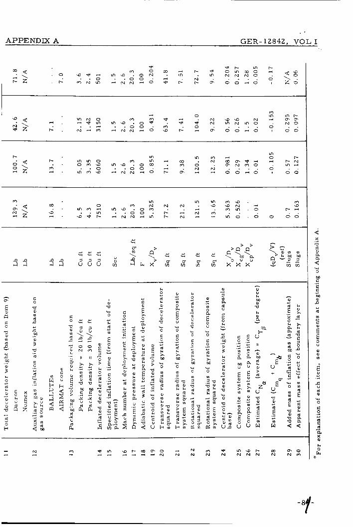
I ’ APPENDIX A GER-12842, VOL I
“. . + \ r - 2
- + - L o r -
m e 0 ln m r -
m N O W N a 9 N .-I m m
+ . N . + m A N N 4 0 9 r- .+ m 0 0 - 0 I 0 0
- . - * m m 9 . 0 % f G 4 N m N m O . N O . . . . . . 0 . . d . . o o . m - 0
W m In m m a . m co 0 m N N N . 9 9 N .-I a . . m m 4 m a . 0 m . . d f m m . 0 r - I 4 - 4 Q 9 m . . o o . r - - N m . . . . 4 3 . G 4 r - M N N d V I t- N - 4 m o . 0 0 a 0
8 G 9 X
a 2 w 0
? .r(
G G M a, P
d m G
.r(
*
Y
i! E 0 U
aJ a, m
E Y .r(
c U d Q)
‘3 0 E: 0
rd c rd a
.d *
+
$ k
S P J J
k 0 *
a, d
A
a, a, k M a, G
a a, m d P
c M
Y
.+
$ 2 ld G 0
d
c
.3 L)
3 ‘3
. A
* d G
I a, a
a, U a, a w 0
G 0
d x M
0
3 a d
a, m k
.3 *
‘3
rn .3
:z b m
G 0
d
G
G
.A Y
.3 4 2 .3
.3
*
; x 0
a a, a d k a, P
3
*
E 2 c U
c 0 -3 Y .3
2 &
E
M V
* m x m a,
m 0 a 0
4 2 .+
E u
E 3 0 > -0
d
G
0
3
Y
3 ‘3
.r(
‘3
2 &
G a, V
*
E“
Ew
V +
V - a a,
d c
E .A Y
m w
N 4
- 89-

a t s . d
' a
m r-
c o o 4
k
m i
cc N
> c
'n V c
rd
h rd M rd
c
+ c
0- m Y
..-4
k a, U 4-2
a Id c. u
E " a J 6 & c
m m o m N C O
N m m I r - m o N O
m . o m . m . 4 m * - . 4 4
P P J J
rd 0 c)
k.

1 APPENDIX A GER-12842, VOL I,
r- m e
0 9 0
- o m . . o m N d
r- s m o m P
d N m 0 O , . .
N
m m
m N
m 4
co d
N
m r - m - C O N - 0
o o c l o . . . .
m 0 ,-4
0 I
9 r - N I n 4
0 0 . .
h
m E Y H
c 0 -0 a, m d D Y
2
3
M a, .+
h 0 d *
2 2 a d a , & u u
4
* d 0 H
c 0
a a, (0
d P
2 M .+
$ 2 d d
rd
c
-3 * 4 w .+
x r n
4 %
0
rd
d
.+ *
.+ * .+
.+ Y
5 E x 0 a a, V
d h a,
+
*
n E 2 c u
3
3 0 > V a,
rd
C
0
4
* 3 '3
.+ w
2 h * c U
w d 0 %
c .r( Y .+ m 0 R M u
€ * m x m a,
rn * .r(
0 R
0 E U
k?
EV
.+ 2
U +
u - V a, *
Y m w
N 4
4
9 x a
a
.+
2 w 0 M C C d M u P
d
C
,+
.+
*
m Y
E" E u al a, a
E
< Y .r.
d a,
0 C 0
d C d a
w
.+ u
d
3 &
2 *

a { A
a '3 -
A
M e, a 0 N 4 - al E
u s 9 I
U 4
r- 0 c o * ln o m . *
. m o l n N m . W d W N d W d
m o d o m c o
Y Y a l a l M M k h d d bk-4
Al I
P P 4 4
% u - k e, P
3 c c
E
U
2 3
-+ +J .3
.+ +
d
c
d d a, k d M d
d a, a l k - e 3 0
0 N r- N
A
2
v
5 d w Y
3
4 2 Id 0 b
E ". " 0
I Z C
87

APPENDIX A GER-12842, VOL I
0 W 0 m r - -l N m m u .
r - 0 m m In . dl . * N m m N -l m 4 4 f a m .. m H . o m a . a . r - N * O . N W r - \ m . . a . . a m . m D 0 r- . . . . 0 . . - l z N . m m + - 4 W d - l O ,-4 N m m o o - l o I d o
0 0 m a l * - N * . r-
m a m m m - m - 4 d W
e . N A N d m - d m d N N a m d . o 0 - 0
- 4 4 . . m d . 0 9 m 4 m - l . o m * In + * m - . . a m . r- m r- 0 . . . . N \ e z
4 s 9 x
a 3 w 0 M c c c M a, e d
.r(
-+
*
m Y e
; E u a, a, m
E Y .A
c u d
-44 0 e 0
d c a a
.+ u
4
2 &
l+ 0
Id k a, a, u al a 0
c
+
w
a, + a, a, k M 0 a k a, a v
a, a
n * w
c o .+ g ' * II .+ v o o
U N W
I1 I1 .,- 0- a, 5 5 L .,- .r(
5 0 > k 0 6 k a, al u a, V
a a, d
3
Y
4
i)
+ w fi
Y
?. 2" c k U
d
N W d
- 8 f -
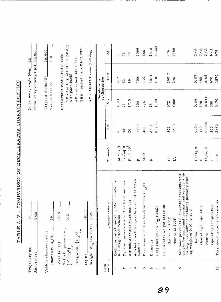
d
a r - 4 w >
t
0 X k
4
00 N
c * L
N 0 C O N 0 0 CO . * a 9
N O O C O V . r-.- ' m m N 4 a N " r - d
N r - m o o o o o r - . m . r - C O
o * o a +
W m 0- m N . 0 9 N N O
.- ' r- 0 m C Q . r - 0 4 r - 4 r - r - N M a d
4
m m o o o o o r -
. m . O H O N O W W
m 0 * o 0 o m . C O N O
N O o o m . O N m m N . - ' * N O C O A
* m m o o o o o w . * .oCO O * O m N
+ U
Y v
rd 0
n U
c)
S W
U
c3 c3 a, 0 U
M Id
.+
.+
6

APPENDIX A G E R - 12842, VOL I
m l n a m l n m 9 m m In
O < - t - d 0 c o c o m . . e m . r- r+l . . . . d \ d t - d - 0 l n m a H m - 4 0 v) r+l K s 0 0 4 0 I z d
N . 0 9 0 9 e * d m m o ‘ “ 0 0
0 9 9 9 . t - l n t - N l n d
0 c o o - 4 9 co a m m ln . + 1 m t - l n N H 0 m
m o 9 ,-I,-IN . c o r n 0 2 2 $ d d r ; d 0 . . a 9 m . m N 4 4 i m u . o d I d o 4 0 . 0 m a l ot- 9 ‘ N . m 9 N O . I n m
4 4 9 x
a 3 il 3 M c c c M a, P
d
c
. A
.+
Y
m *
; E 0
0 a, m
E Y .A
A U d Q)
0 d 0
d c d a
u
.A *
+
x, k 0 L 4
c
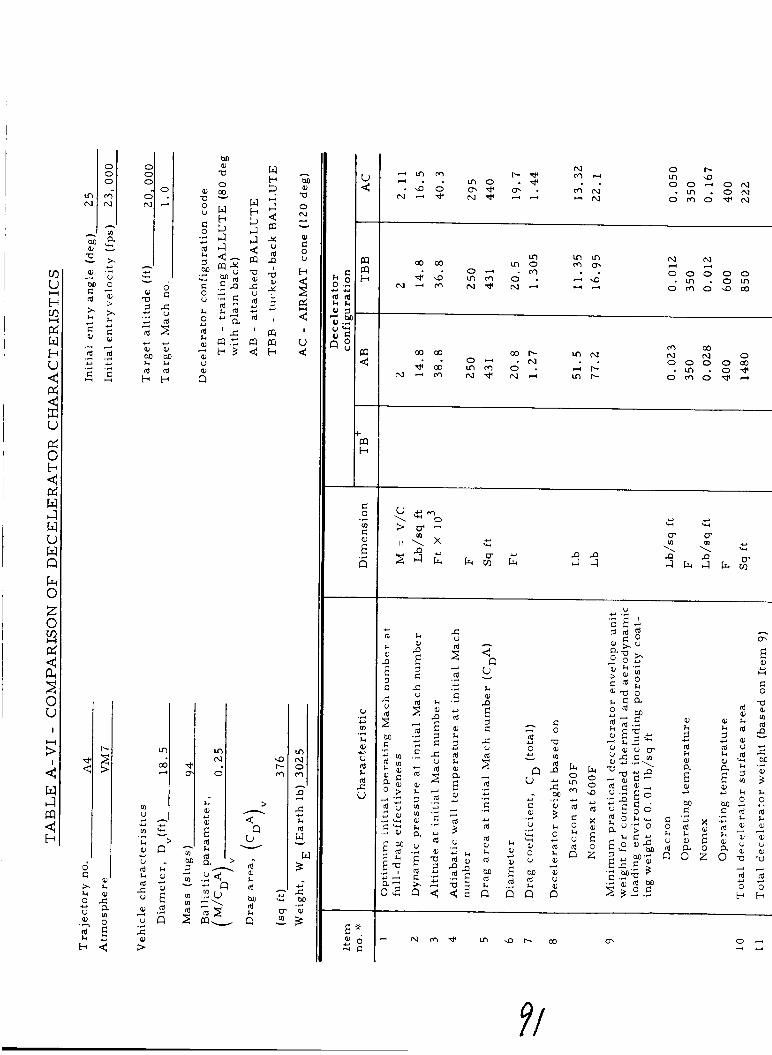
Y Y U Q J M M 8.l- L- d d b b
VI u
v)
h a,
u d
d c u e, V
c
.e Y
.e
Y
3
.e
Ln
co d
h Y W -
> n k al Y
; d .+ n
m N * . I; 0
a r- rr)
. - Id e, h Id M d
U .r( 4 2
u)
8.l .r(
a,
U c)
Id c u
o r - m a 0 0 d O N
. m O N o m d v n ,
d d
0 0 0 0 0 . m . o m o w o 9 w
w w " 0 o o o o w . m . o * o m o + - ~
P P 4 4
* W 42 W
d k a,
: $ : 3
<n V - k QJ P
3 C c
E
U
5 i
Id
c
Id
d e , &
.+ Y .C
.e
Y
d
- + Y
4-2 - d 0
n u Y C e,
u % * al 0 u M d
.3
.3
6
C h u
d
- o\
E Y U
C 0
a a, v) d D - 2 M .3
; k 0
d h e, a, u a,
73
d 0 b
Y
i
*

APPENDIX A GER-12842, VOL I
9 -4 N m N d m m m
4 z m N * ul m m m G- m m v o 0 m N . . m . . r - r - . L l i s d m . . . . d \
1 - 4 * . m N H F d N , + m o * N co N 0 0 0 0 I 2 0 & * m N - 0 0 ' O N F O
m m a ul * * L n Ln 4 N W * N 6 m F N 0 m N . . N . m m r - m 4 O N N N r - 0 . 0 0 o m * * 6 N N N . 4 0 - 4 4 N d m O * N 9 N 0 0 0 0 I 0 0 . . . . a m . 0 9 9 9 . . . . 0
3
* C
x
R a, V
rd a, k
rd
a, R
3
*
2
E 42
3 3
$ U
d P rd
-3 *
; 3 0 > -0 a,
d
C
0
3
L)
3 W
.3
W
2
5 0 u
U
k 0 rd
a,
01 U 01 '(1 '3 0 C 0
d k x M
0
1
4 4
+
.3 c)
'3
m
s 2
?:
a, m k
b m
a,
3 a rd
3
m
U
E
2 k W u
M .r(
; k 0
d a,
a, U a, V
0
L)
3
w
2
za , a:
k h
V O
- a, 01 k M a, V k a, R -
Q
E"
EW
U +
U - a a, c)
.3 5 u
r l
N 3
h 0 u e, (d k
v)
U
.T
U
2 k 0 w a a,
d 9 ld
U
d
5 2
;
42
a, k
m U
m k e, u d
(d A u
.r(
.+
c)
+

I u 4
x u
I I 2
PG 0 b 4 P;; w 4 w u w Q 6( 0
4 pc
U Y 0 0 M M h d b
v) U
m k P)
u
.+ *
.e
c)
2 d c U
P)
U +
2
U 0 n
VI 9 N P O o m
>
'n u - k d M d
n
.r(
v) c
E" 6
U .+ U
0 .r(
h 0 U Y
E " a d S C
r - 0 m 9 0 d o d d c o .In r-
o m d V 9
m m m m r-
0 0 . o . 9 0 0 0 d . d m
N d * m c o m . - l e 9 d
2 2 z o 0 0 O N 0 - I n 0
o m d V N
00 coo N N O 0 0 0 0" .In N
o m d v m
m a N c o
. m . o m o m o * - I
N 0 0 o o m
c 0 V P) v)
. . al u
B

APPENDIX A GER-12842, VOL I
t- N rr) Q) a m t- t- a m 0 * m * m N . Q) e m m N 0 W C O . . m . m N a m N . m m . . a . * N - 4 0 . m o m a . . - 4 . . t - t - . m CO VI to . . . . 0 . .
a * t - . m N t - d N - 4 m O 6 N d N 0 0 - 4 0 I O 0
m m m t - a m . .
- 4 - 4
m m -4
* 0 -4 .-(
N
rr)
2 N
t- m
0 2 - 4 N P C O d + N O 0
0 0 - 4 0 . . . .
* 0
0 I
Q) C O N m - 4 0 0 . .
a . Q)
N O
m 0 N N t- N CO rr) * m m -4 m m
. . 0 . m N Q ) m m . o t - . . t - m . o . . m . . a m . d t- a -
, P P ~ 4 4
cn E
i o
* H
G
a a, m d ~e
i 2 M .3
3
* Id 0 'b
G 0
V al 10 d P a 0) k .3
k
; 7 0 > M G
M d x u
3
.3
2
E" 1 0 > k 0
Id 0 al u al V a al
d
+
*
3
* 3 '3
3
al a w 0 2
* G
; x 0 a a d a, k 1 m 10 al k a u
3
*
.3
E z a"
k 0
d a,
a, u 0, a '3 0
c
*
4
.r( * 2 x M
0 '3
? .3 a d
a, m k
:z b m
' 3 d o u
' 3 M o u m 0
G 0 .* * .A
m 0 a M u
E i)
m x m al
m * .+
0 a 0 E U
c 0 .+ 4-2 .r(
m 0 a a u
E * m x m a,
m 0 a
* .+
E u
h
P
Eo-
u +
u - a a, +
.r( $ &I
m w
h
* a,
.3 3 3 a a d
m d M G 0
6
E
0 m m
- .3 4 2
3 '3
.r(
'3
d E -0 a, a :
k a, x d 3
2 d a c 1 0 n w 0
u a, w w a,
m m
*
$ * G
k
8.
3 N 3 H
4
s 9 x
a 2 '3 0
M G G G M a,
.r(
.3
n CI
a m c Y
; E u 0 a, m
E c1 .r.
c u a
L 4 0 d 0
a c Id a
.3 Y
+
3 : &
c

k d e
m U
m k al U d
d c U
o, U
... c)
...
Y
3
2
M a a 0 -
$ S 2 w k
W
In 0
... o, 3
u v)
.r( c)
U
E ". 0 0
S C
VI " . V I 9 0
o m . o . . u , F m a - I . - I F
dm ~m N - I A A
u,
m m m - 4 m
o m . N . . m r - m a c o . 0 0
~ - 4 m ~m - 4 - 1 * a
h
% u - k a, n E 3 c c U
3 3
d
c:
d Id e, k d M d k
... Y .3
... c)
n
k o, Y
E" Id 6
h 3
Y
Y - d 0
n u C o,
U
b+ % a 0 U
M d
42
... ...
6
c k U
d
O. 0 31
. N r n * m a r - 0 0

. . APPENDIX A GER-12842, VOL I
F m m In c o d W to
c o c o 0 * N 2 N d+ * 9 0 + A a m . . 9 . . m o . co t-' 4 . . . . . 0 . . m 4
L n ' \ m a a . d N d W O * co co O O d O I 0 0
a F N M O . N O N . F - W m o . 0 9 .
f
c 0
V m m Id P
c M
Y
-+
i 2 Id c 0
d
c
.+ Y
3 '3
.3
m Id Ma,
2 0' + .3 m
5 : 4 M
I a, a ' 3 c 0 0
E 3 0 > -0 m d
d
0
+
Y
4 '3
-+ w
3
9 0 k Y
u
k 0
d
a, a, U a, a w 0
c 0
*
A
.C U
2 x M
0
3 a d k
a, m k
'3
m .+
? ? z : 2 $ e m
a, 4
m -
c 0 .+ Y .+ m 0 a M U
E Y m x m m m Y .+
0 a 0 E U
a, m k M
V k m a -
m
m Y
2 ; d .+
8 - k x a k a d d a
- e
N 3
4 5 3 x
a : w 0
M c c e M a, P
Id
c
-4
.A
U
0 Y
; E U
m m m
E Y .r(
2 u d
-4 0 c 0
d c d a
.r( 4-2
4
x, h
- 96-

m 0
0 U r
c
CA
h
M aJ a 0 N d - aJ c:
rd W Y
P
U
u)
k
.+ *
.+
aJ 4 2
V ld
m m m N . m o m r -
m N m m m ~ d d N
. . o w . o m i N I n I - 4 . m m
In w N . - 0 3 * .
o w . N e *
m r u m m m d d r - d m i N m m . 0 0
m N In N . m m m . . o o . w . r -
m * N O W . c o d m N m m ~ d o r - l - i
u w
k aJ P
3 G r U
E
2 4
.+ * .+
.e
4 4
d
c
d Id aJ k d M d k n
C
P aJ In
c k U
d

APPENDIX A G E R - 12842, VOL I
* r- m N . m w
#-I a m . o m . 0 - 0
I , . . m m o * r - d + N m o d . a * m r n 4 . 0 6 . 4 " <
. . . . m \ 0 . . m P - N w a O \ - 2 * . s ' i m - m N m i * - a - m 0 . d 0 0 0
c a e, m rd n c M
42
.r(
$ 2 d
E" 1 0 > k 0 d e, e, u e, V V e, rd
4
*
+
c 3 w El
.r( c * .r( * .r(
.r(
*
rd
c
c
E" x 0 a e, a d k e,
3
c.)
n E
5 1 c
E 3 0 > a
rd
c
0
3
* + w .A
w
2 k
C e, u *
k 0
d e, e, u e, a 0 c 0
rd
x M
0
m 1
d
e, m k
*
4
c(
.r( 42
w
s
:z B m
k 0
d e, a, U e, V w 0 G 0
*
4
.r(
U
2 x M
0
m 1 a
13
.3
2
.o, 3
d G V
* k d d z g d m
c 0 .r( * .r(
m 0 a M u
E Y m x m e,
m 0 a 0
* .r(
E U
e, e, k M a,- a k e, a Y
P
EV
u +
u - V e,
rd *
E .r( Y
m w
X a
a
.r(
5 2 c( 0
M c c d M e, .n
rd m c
.r(
.r(
L)
.c)
E" E u a, e, u)
E Q)
c rd
Y -r(
U
k-i 0
0
Id c d a
..-I Y
4
2 h
*
- 9t-
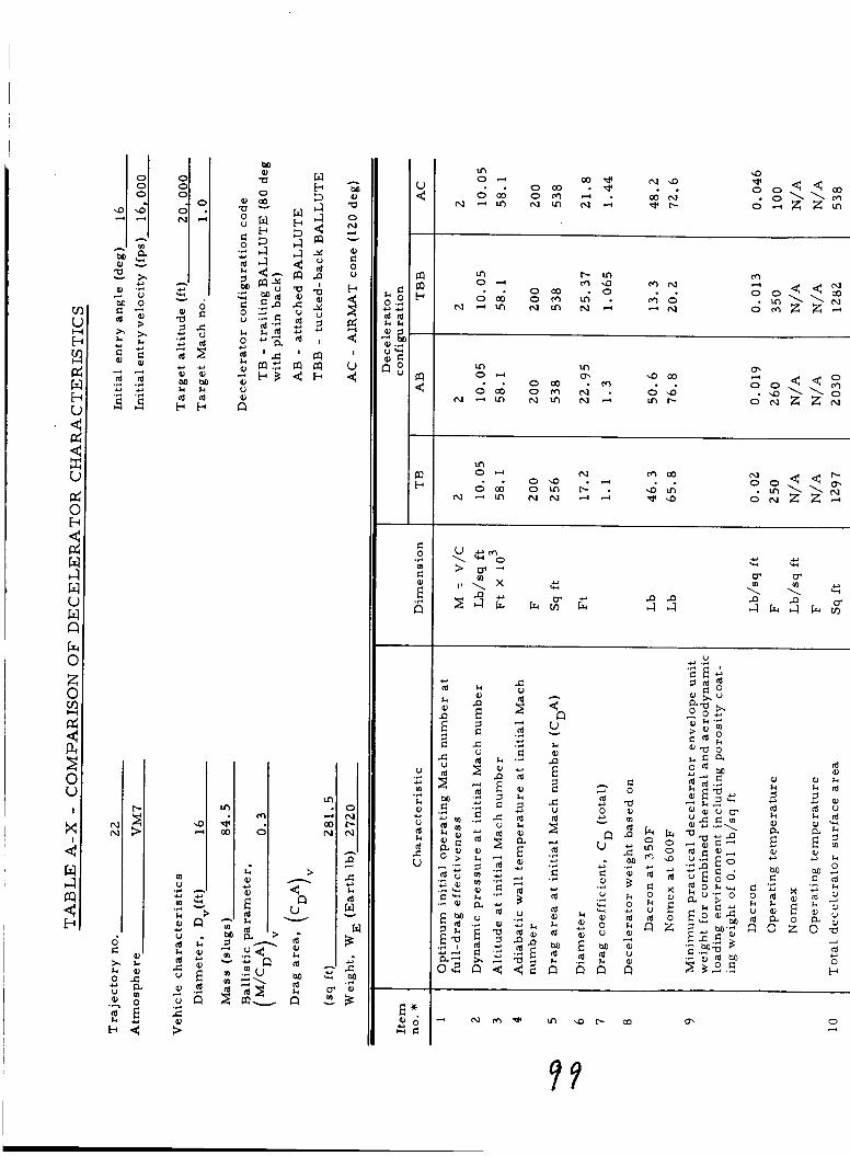
d d .r( ... c ) Y .e ... I $ &
m
m k 0 U
d c U
W
U
U ... Y
... Y
2
d
.4 c c
bo al a
3 - u - d k d M
2 tl
w t-c 3 c-1 c-1
2 Y U d P I a al Y U 7 Y
I
m a t-c
U .3 * .r( m & al
U Y
c
E * " 6 = ; E
rr) 0-4 a 3 d r N 9
* . o m . * . . 0 0 0 o m d . a 3 N
N d m N m N d d r t -
m P m 0-4 m a m N - . oco . o . . o m o m I n . m o
N - 4 m N I n N d -4N
rn
m In O H m 9 0 3 . . o m . m . . oa3 o m N . 0 9
N - 4 m N m N d m t -
m 0-4 N m a 3 . . 0 9 . - 4 . . oco o m P * a m
N d m N N d d c y 9
k al P
3 E I:
E
U
3 3
-4 &i .r(
.r(
Y
d
c
d al k 7 m al k a U
'2 a" d C
k e, P
3 C c
E
U
3 3
.3 Y .d
.r(
Y
d
E
d al a 3
4-l -4 Y d
e
c U
d
... * ... d C
d e, k 7
... *
42
2
E a
* 3 3
d 3 U ...
<* u w
k o P
3 E Ld
E
U
2 3
.+ * .+
... Y
d
C
d d a, k d M d
h 0 *
E" d s
3
42
4.2 w
d 0
n u c! *
.r(
-4 U
-4.4 * al 0 U
M d
6
C 0 a a, m d n 2 M .+
i k 0 d
o al U
*
3
B
Irr 0 m m
d C 0 k U
c)
: C k U
d 3 ,
* rd 0 e
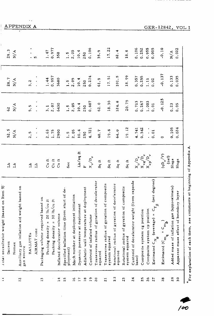
~ APPENDIXA GER-12842, VOL I
r- 9 N a N m m 0 N
e g . m + o m 4 N d N O rr) - co 4 0 0 0 0 I z d
r - r - m d 0 o- N * w o r n m o 4 * m a l m o . O d - . d N 6 0 . . m . . o m . m r- N w . . . . d \
m l- 9 Q) m r - m N
d 9 0 d 4 m m
9 2 m . m ' N S d N d N 0 9 4 u 0 0 4 0 I 0 0
1 - 0 m * 0 0 m c m . + o m m o . 0 9 . . d 0 1 - N O 0 . N O N \ . * . . o m . N Q) N . . . . 0 . .
d N m d . r - m . o 4 0
r n d N r- w 0 * G G - 4 O N
A \ . . o - . . o m 0 . ; d m . . m z N . N 4 N d N d N 4 d 4 a 4 d d . d 0 0 0
m m 0 m . 9 r - 0 m o . o r - .
d 0 k 0
8
U '3
2 2 \
0 W
I I
x
c a
Y .r(
m
F
2 .+ 3 U
al
1 0 > k 0
id
al e, U e,
a e,
cd
E 3
*
3
* 3
I al a '3 0
k d *
* m
E 0 h '3 Y
E" .+ U
C 0
d
C
.+ 42
d
- 2 2 e,
.+
vla
C
d
d
d
.+ U
.+ * .+
.+ Y
E" x 0 a e, a d k e,
4
*
n E 2 c
2
1 0 ' -0
d
C
0
3
* 4 '3
.+ '3
2 k Y c u
k 0
ld
al
e, U al '0 '3 0
e 0
*
3
.+ * 2 x M
0
3
ld
al m k
'3
m
ti
:; z : 2 g b m
al U .+ m 0 a 0 E U
'3 0
e 0
ld x M
0
.r( U
'3
m 2 -0 a u I d h 4 k $ z g .41 E d 2 Y
al 4
2
E
2
a ld
0 k '3 w
M .+
t k 0 Y
2 3 al U al a 0 '3
s
0:
0 k h
V n
C 0 .d U .+ m 0 a M U
E U m >.
0, I-' .+ m 0 a 0 V E
0 al k M
P k al a w
-4 -4
N 3
W 4
4 s 6,
x
a 2 '3 0
2 .+ C d M al
-+
n Y
d m c *
; E 0 U
P) al m
E Y .d
c u d a, '3 0 C 0
.r( Y
d a 4
1 h

* 0) M k
G
w U
m k a,
U
.r( u
.+
*
d 5 d
a, U z
2 >
* a, M
d H
k 0) Y
E d .3 n
M P)
0
a W
U
6
c m M I m m m
3
Y
$3
d a, k d M d
U
E *. Q ) O Z C
m r- 0 4 O N D m . . o m . o . . oco o m c o . r - c o
N - l m N 9 N - l - l *
M
4 2 W c W
k Q) P
3 c c U
E
3 4
.+ * .r(
.r(
*
d
C
d a, k 3 m m a, k a U
'2 a" d C
k a, D
3 C c U
E
3 4
.+ * .3
.+ *
rd
d
d a, U 5 * .,. * 4 4
4n V Y
k a, P
5 d e
E
U
5 4
.+ * .r(
.+ *
d
d
d d a, k d M d
2
4
Y
* Y
d 0
n V * C a, .+ U .+
W W
a, 0 U
M d
5
C
U a, m d P
2 M -4
i k 0
d a,
a, U
*
4
d
Fr
m
d C 0 k U
0 u-l
Y
&
d 0 k U
&
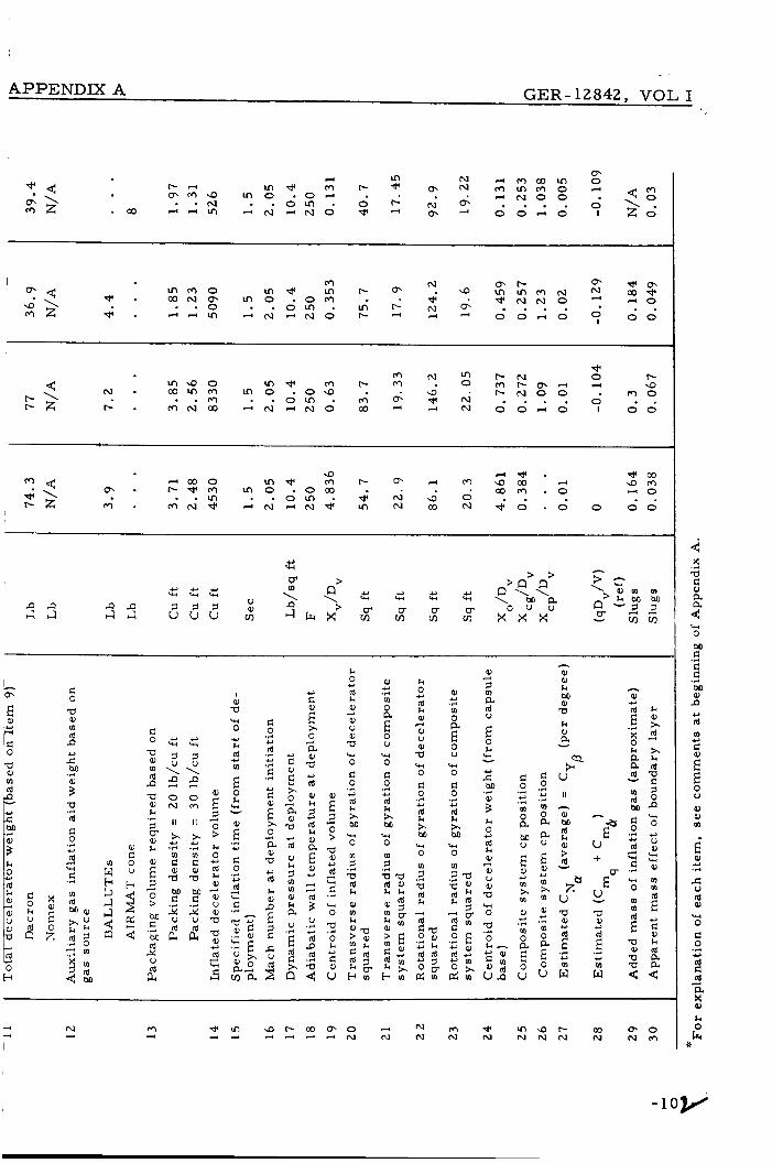
APPENDIX A GER-12842, VOL I
c 0 -0 e, m d P
c 4 2
M .r.
; 2 d c 0 .r( *
2 w h
c 0
a al m d P a a, k
5 G- a, k
.3
E" 5 0 > M C M d 3
4
.3
U
a"
='tl 5
5 4
0 N
II
x 10 C a, a M c
* .r(
E
2
Y w
8 ff \
0 m
I I
x 42 .r(
: a M e 3 V
.r(
a"
; 1 0 > k 0 d a, al V a, a a a,
d
3
*
4
* 3 w 3
I a, -0
0
k d
W
*
Y m
E 0 k w Y
.r. E" c)
c, 0
d
c
.r( c)
3 w - .r.
a; .? 0) 2 E : g ad m a
c 0
d
C
c
.+ *
.r. * .+
.r(
*
E x 0 a al -0
d k a, D
3
*
E 2 5 3
Y c
E x a a, a d a, k 5 m m a, k a V
3
*
'2 2
E 2 0 > a a,
d
C
0
42
3 W
-r(
w
2
E,
0 4 2
u
k 0 d a,
0) V 0 a W 0
c
d k x M
0
5
d
Y
3
.r( 42
W
m
6
al m k
:2
H m
a, * .3 m 0 a 0 V W 0 c 0
d x M
0 m 3
d a l k k
E
.r. c)
w
6 a
0 4
2 E i: e a b
H m
al 3
2 z E
2
a
k w w
M .r.
i k 0 * 2 + 0 V al a 0 w
2
s : k -
Q ) d U n
c 0 .r. c) .r(
m 0 a M V
E * m x 10
al
m * .r(
0 a 0 E u
0
m 0 a a
.r( Y .r(
V
E Y m x m 0
m 0 a 0
Y .r(
E u
h
0)
k M
a k e, a - aQ u
II
al M rd 0 > rd - 2" u a a,
d U
E .r. 42
w
h
* 0) d
X 0 k a a d
d M c
rd
C
0
E .r(
w
m
.r( c)
4 w .r(
W
m m d
a al a
E
k al x d 3
5 d a E 5 0 n * 0
V al W W al
m m
*
2 * c 0 k rd a
i: N 4
0 4
4 6 9 X
a %
? L 4 0
.r( c e M e, P
d
e
.r(
*
m *
E E 0 u Q) al m
E P)
s u rd al
0 c 0
d c d a
Y .r.
Q-4
.r( Y
d
1 2 k
- 1 o v
GER-12842, VOL I
APPENDIX B - REFINED POINT-MASS
TRAJECTORY COMPUTATIONS AND
TRANSIENT HEATING CALCULATIONS
The f igures in this appendix present the space / t ime
and envelope transient t empera tu re h is tor ies of the
dece lera tor envelope fabr ic fo r the en t ry cases in
Table I11 of this report . The envelope fabric in a l l
ca ses was dacron.
-103-


32
2E
2c
16
12
8 m- 2 X
I- W W LL4
W 0 3
I- J 4:
-
b
0
T U C K E D - B A C K B A L L U T E _- A N D A I R M A T C O N E
1 2 3 4 5 M A C H N U M B E R
I60
140
120
100
80
60
40
- In
20 0 u W
W 5
In - -
' 0 I-
480
40C
32C
24C
- t W I Z W (I: 160 I 4: IL
W (I: 3 I- a (I: W a 8C 5 W I- W
0 J W > z
-
a
W c - MACH
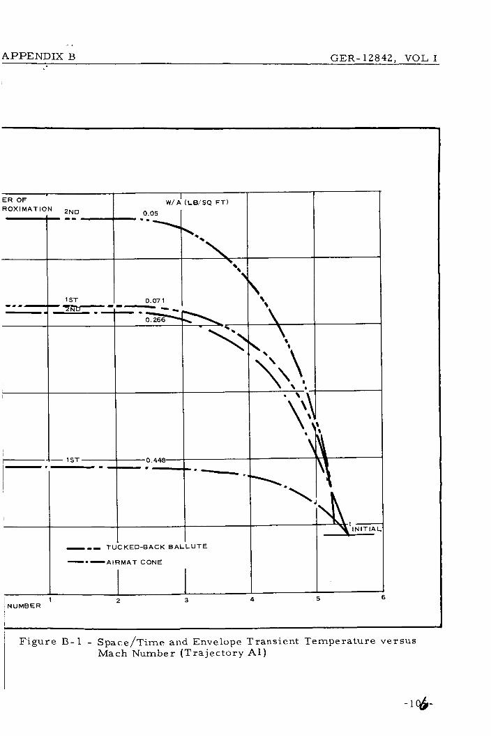
APPENDIX B GER-12842, VOL I
1 N U M B E R
1 I
- -- TUCKED-BACK B A L L U T E
---AIRMAT C O N E T L I N l T l A
4 5 6 2 3
Figure B- 1 - Space /Time and Envelope Transient Tempera tu re versus Mach Number (Tra jec tory A l )

28
24
2c
16
12
8
m- 2
I - 4
X
W W ll.
W 0 3 I- I- -1
- -
4 0
T I M E -
r T T A C H E 1 A L L U T E
M PACT
70
$0
50
$0
30
20
10
0 0.8 1.6 2.4 3.2
MACH NUMBER
- VI 0 z 0 u W VI
W
I-
- E

. <
, APPENDIXB GER-12842, VOL I
140
12c
1 oa
BC
60
4c
ORDER OF A PPROX I M
- k W I z W U I a
W U 3 l- a U W
r W I-
t 20
a
C
M A C H N U M B E R
I I --- - A T T A C H E D B A L L U T E
- - - TUCKED-BACK B A L L U T E
-.- A I R M A T CONE
F i g u r e B-2 - Space/Time and Envelope Transient Tempera tu re v e r s u s Mach Number (Tra j ec to ry B3)
- 10%
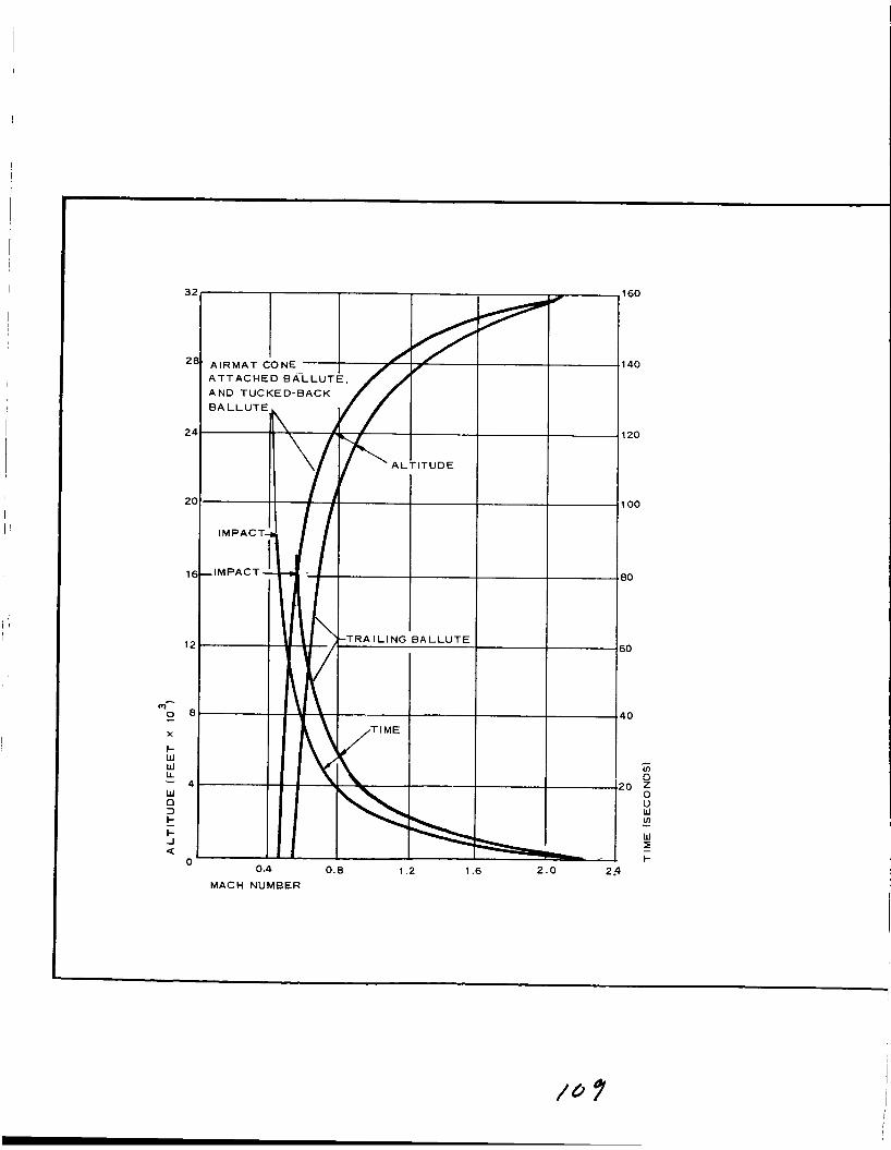
3
2
2
21
11
1;
m- Z t X
I- W W LL
W 0 3
I- -I
4 -
t
a 0
0.4 0.8 1.2 1.6 2 . 0 2.4 MACH NUMBER
I60
I 4 0
I20
I O 0
30
io
I O
ffl 0
10 = 0 u W
W I I-
ffl - -

APPENDIX B G E R - 1 2 8 4 2 , V O L I
, MATERIAL U N I T WEIGHT (LB/SQ FTI
1ST APPROXIMATION 2ND A P P R O X I M A T I O N
40k A T T A C H E D B A L L U T E 0.0204
TUCKED-BACK B A L L U T E 0.01 12
I A I R M A T C O N E 0.078 Z
O . O P 5
0.016
0.012
0.049
W U I a 5 2c W K 3 F
U W Q 5 W
a
0.4 0.8 1.2 1 .6 2 . 0 + o MACH NUMBER
F i g u r e B - 3 - Space/Time and Envelope Trans ien t T e m p e r a t u r e v e r s u s Mach Number (Tra j ec to ry 19)
-1qe
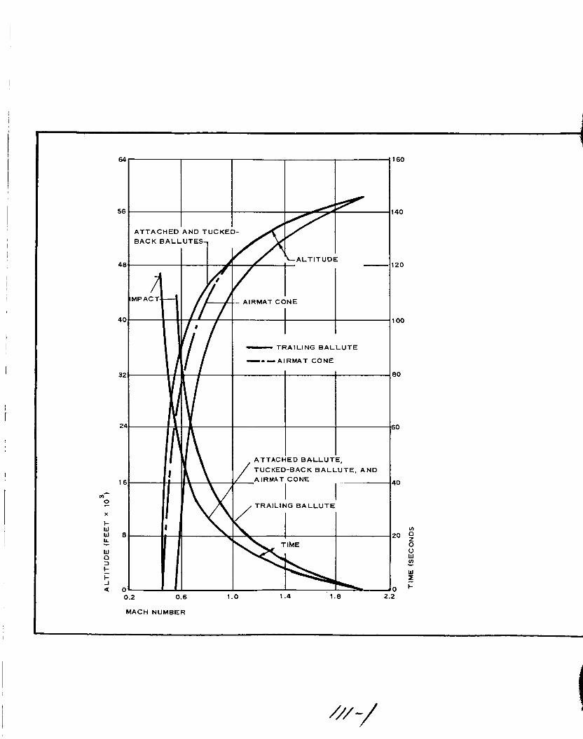
5
5(
41
4(
3;
2
11
I
0.2 0.6 1 .o 1.4 1.8
MACH NUMBER
60
4 0
20
00
&/-/
In 0 z 0 u W In
W
t-
- 5

I X B GER- 12842A, VOL I
240-
zoo
160
120
80 - k W I z W LL I U - 40 W LL 3 I- U LL W
I W I- 01
a
O R D E R O F A P PROX l M A T l 0 N W / A (LB/SQ FT)
1ST 0.01 1 - ----- ’ 1
1ST
-= -=- -- .- 2 N D
2ND
2ND 0.019 -- ---- ----- --E --e-- 3r ---- 1 1 S T
I
2ND --- 1 S T
--(I
t I N I T I A L I I - T R A I L I N G B A L L U T E - - - - A T T A C H E D B A L L U T E
- 0 0 TUCKED-BACK B A L L U T E
-. - AIRMAT C O N E
0.2 0.6 1 .o 1.4 1 .8
M A C H NUMBER
2.2
Figure B-4 - Space/Time and Envelope Transient Tempera tu re v e r s u s Mach Number (Tra jec tory 22)
Revised 21 October 1966 - 1 1 1 - 2 ,

MPACT,
,TIME
TUCKED-BACK B A L L U T E , AND ATTACHED B A L L U T E
I 1;' I
I I
I
---- A T T A C H E D BALLUTE - -- TUCKED-BACK B A L L U T E
1.4 1.8 2.2 0.2 0.6 1 .o M A C H N U M B E R
240
200
160
120
80
40 - In 0 z 0 u W In
W z
3 +
- -

. .
APPENDIX B GER-12842 , VOL I
140
ORDER OF APPROXIMATION
W / A f LB/SQ FT)
120 2 ND -- -
2 ND -- .- - - - - ---,--- - -- 1 S T 100
- -- TUCKED-BACK B A L L U T E
80
h 0.01 9 I ‘1
Figure B-5 - Space/Tirne and Envelope Transient Tempera tu re versus Mach Number (Tra jec tory 23)
- 113’-
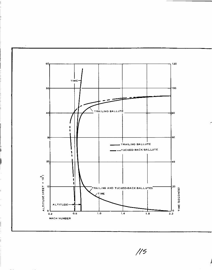
I TIME-
0
A / T R A I L I N G B A L L U T E
I I
- T R A I L I N G B A L L U T E
- - ,TUC K E D-BAC K B A L L U T E I 8
T R A I L I N G A N D TUCKED-BACK B A L L U T E S
20
0.2 0.6 1 .o 1.4 1 .e 2.2
M A C H NUMBER

I .
80.
60
I
40
20
0
YPPENDIX B GER-l2842A, VOL I
I 1ST A N D 2ND APPROXIMATIONS FOR B O T H D E C E L E R A T O R S
\
M A T E R I A L U N I T WEIGHT (LB/SQ F T )
1ST APPROXIMATION 2ND A P P R O X I M A T I O N
T R A I L I N G B A L L U T E 0.018 0.015
TUCKED-BACK B A L L U T E 0.0112 0.012 -
0.2 0.6
MACH NUMBER
1 .o 1.4 1 .e 2.2
Figure B-6 - Space/Time and Envelope Transient Tempera tu re v e r s u s Mach Number (Tra j ec to ry 3 0 )
Revised 21 October 1966 - 1 1 u -

GER-12842A, VOL I I
APPENDIX C - DISCUSSION O F DYNAMIC STABILITY
ANALYSES
1 . INTRODUCTION
The determinat ion of the dynamic motion charac te r i s t ics for a recovera-
ble space vehicle landing on the sur face of M a r s with attached o r t ra i l -
ing aerodynamic dece lera tors is a p r i m a r y requirement .
cha rac t e r i s t i c s will predominantly affect the design of t e rmina l impact
control s y s t e m s , whether they a r e of the hard- o r soft-landing type.
The motion
Additionally, a s shown by the r e su l t s of this study, there is relat ively
l i t t le weight advantage indicated for a par t icu lar dece lera tor configura-
tion on a drag per formance basis.
t icular configuration largely could be dictated by dynamic per formance
cha rac t e r i s t i c s .
Consequently, the choice of a pa r -
The weight analysis developed in this study was based on s ta t ic a e r o -
dynamic loading relationships with empir ical ly determined, quasi- s ta t ic
load, t empera tu re and design f ac to r s employed to account for operating
environmental effects and ma te r i a l cha rac t e r i s t i c s . This weight analy-
sis of necessi ty preceeded the dynamic ana lys i s , a s suming adequate
aerodynamic stabil i ty of the var ious configurations and l i t t le dynamics
interact ion with the decelerator strength-weight requi rements .
interact ion is discussed subsequently in this appendix a s re la ted to the
attached dece le ra to r configurations.
This
T h e development of a n adequate mathemat ica l model formulated for u s e
with high-speed digital computer equipment is a prerequis i te to analyze
dynamic motion and to secure resu l t s within reasonable t ime sca l e s .
The dynamic motion about the flight path of a n aerodynamic expandable
Revised 21 October 1966 -117-
APPENDIX C - DYNAMIC STABILITY ANALYSES G E R - 128424, VOL I
dece le ra to r is quite complex; par t icu lar ly , i f spin about the longitudinal
axis of the en t ry capsule is p re sen t p r i o r to deployment of the dece le ra -
to r device. Spin may be induced intentionally o r be p re sen t inherent ly
f o r rotationally s y m m e t r i c bodies t r ave r s ing entry-f l ight paths .
tentionally induced spin (usually sma l l , about 1. 0 r ad / sec o r l e s s and
not intended for spin s tabi l izat ion) p r i m a r i l y min imizes deviations f r o m
the flight path as a r e su l t of l a t e r a l cg to le rance and e n s u r e s s y m m e t r y
of heating over the forward portion of the en t ry capsule .
In-
During the ear ly IRBM and ICBM nose cone development p r o g r a m s , i t
was found that nose cones not intentionally spun would develop inherent
spin during en t ry through the e a r t h ' s a tmosphe re as a r e s u l t of l a t e r a l
cg to le rance and a s y m m e t r i c ablat ion when'incorporating this method of
heat insulation.
the o r d e r of 0. 2 r ad / sec .
ax is control sys t em with aerodynamic o r je t - reac t ion cont ro ls .
Typical sp in r a t e s encountered in this m a n n e r w e r e of
The a l te rna t ive to spinning is anac t ive , t h ree -
F o r the c a s e of a n aerodynamic body with a t ra i l ing aerodynamic de-
ce l e ra to r , there a r e 18 deg of f r eedom when the motions of the r i s e r
and suspension s y s t e m between the forebody and t ra i l ing dece le ra to r
a r e considered.
- i. e . , forebody, r i s e r and suspension l i nes , and t ra i l ing dece le ra to r can
be t r ea t ed a s rigid bodies.
w e r e considered fo r each component, then the s y s t e m has 36 deg of
f r eedom.
t r a j ec to ry of an en t ry body and t ra i l ing d e c e l e r a t o r f r o m deployment to
impact , using the requi red integrat ion in t e rva l s , would be prohibi t ive
o r a t l ea s t unrea l i s t ic even with the highest speed and capaci ty digi ta l
computers available.
This a s s u m e s that each of the s e p a r a t e components ,
If f lexibil i ty and tors iona l deflection modes
The solution of this motion descr ip t ion during the r e a l - t i m e
Exper ience has indicated ( a t l e a s t f o r pu rposes of p a r a m e t r i c analy-
s e s ) that the physical descr ip t ion f o r the dynamic motion of a body can
be approximated reasonably by neglecting f lexibi l i ty effects o r by in-
troducing this considerat ion a s a modif icat ion to rigid-body p a r a m e t e r s
- 118-
I D I I I I I I I I I I I I 1 I 1 I I
I I I I I 1 I I I I I I I I I I 1 I I
APPENDIX C - DYNAMIC STABILITY ANALYSES GER-l2842A, VOL I
and coefficients. Additional simplifications in the mathemat ica l formula-
tions can be made with appropriate assumpt ions and approximations such
a s l inearization of non-linear t e r m s , s m a l l angle approximations, in-
var iant p a r a m e t e r s , constant coefficients , etc . F o r bodies defined as
having rotational s y m m e t r y and weight distribution, the proper choice
of body re ference axes about and along which the motions can be de-
sc r ibed el iminates c r o s s products of iner t ia and decouples pitch and yaw
angular r a t e s f r o m the rol l mode s ince the t r a n s v e r s e moments of i ne r -
tia of the body a r e implicitly equal.
accelerat ing in longitudinal flight o r is nea r te rmina l velocity conditions,
the longitudinal force equation usually m a y be s u r p r e s s e d and the space-
t ime h is tory adequately described by sepa ra t e , m o r e s imple poin t -mass
t ra jec tory computations .
Additionally, i f the capsule is not
2 , ANALYSIS
Goodyear Aerospace has developed in Appendix B of Volume 11, equa-
tions of motion with six and eight degrees of f r eedom to descr ibe the
cha rac t e r i s t ics of composite sys t ems with attached o r t ra i l ing ae ro -
dynamic dece lera tors entering planetary a tmospheres .
tions w e r e developed for use with the IBM 360 ,computer s y s t e m availa-
ble a t the Goodyear Aerospace computer faci l i t ies .
planation of this formulation is made in this appendix.
i l lus t ra te what fac tors and p a r a m e t e r s a r e important in the force and
moments affecting the motion cha rac t e r i s t i c s of composi te en t ry capsule/-
dece lera tor sys t ems , the following simplified equations a r e s e t for th
using conventional a i r f rame-dynamic-stabi l i ty notation.
i s not the s a m e as employed in Appendix B of Volume 11.
The formula-
No additional ex-
However, to
This notation
F o r the cases of a n en t ry capsule with attached dece lera tor configura-
t ions, the fo rce and moment equations m a y be wri t ten in t e r m s of pr in-
cipal axes of a body.
pendent of the angular motions about the axes and a r e constant with the
resu l t that' all products of inertia a r e eliminated.
Thus, the s y s t e m moments of iner t ia a r e inde-
-119-

APPENDIX C - DYNAMIC STABILITY ANALYSES GER-12842AY VOL I
a F o r c e equations
Moment equations
The summation sign implies consideration of all appror ia te aerodynamic
factors f o r both the vehicle and dece lera tor .
and a s used in the study, the t r ansve r se moments of iner t ia w e r e defined
a s equal, eliminating effects of iner t ia coupling in the rol l -angular acce l -
erat ion equation.
pendix A, the iner t ia coupling effect is about 10 percent of the c ross -p lane
angular velocity for e i ther the pitch o r yaw angular acce lera t ion equations
The effect will be osci l la tory in accordance with the sign of the c r o s s -
plane angular velocity s ince the ro l l damping was negligible and the roll
ra te remained constant in the computations of this analysis .
roll-angular accelerat ion equation is eliminated f r o m fu r the r discussion
in this appendix.
As previously noted above
Using I tems 2 1 and 23 of Tables A-I11 and A-XI of Ap-
Thus, the
The pa rame te r s (g) and (c) given below f o r t r a j ec to r i e s 19 and 22 a r e
a See Lis t of Symbols a t the end of this appendix f o r definition of t e r m s .
- 120-
1 I I I I I I I 1 I I I 1 I I I I I I
~

APPENDIX C - DYNAMIC STABILITY ANALYSES GER-l2842A, VOL I
I I I I I c I I I I I 0 1 I I I I
evaluated a t init ial operation and nea r te rmina l conditions for each attached
dece lera tor configuration f rom Tables A-111 and A-XI.
P a r a m e t e r s for t ra jec tory 19 (VM8)
AB
(SI i 65
(g) 1 2 . 3 t
91
P a r a m e t e r s for t ra jec tory 22 (VM7)
AB
(,) 1 2 . 3 t
(E)i 6 6
1 3 . 9
TBB AC - -
85 59
14. 4 1 2 . 4
147 8 5
25 17. 8
TBB AC - -
7 4 52
13. 5 1 2 . 9
106 65
19. 4 15. 1
The variation in values tabulated above a r e indicative only of the differ-
ences in geometry of the decelerators s ince, for prac t ica l purposes , the
dynamic p r e s s u r e , q, i s the s a m e and the m a s s (m) i s identical for a l l
cases . Note that the values for these p a r a m e t e r s in both the force and
moment equations a re of comparable magnitude.
-
-121-

The fac tors compris ing the aerodynamic t e r m s contained in the force and
moment equations with a l l coefficients r e f e r r e d to body axes a r e given be-
low.
F o r c e equations:
Moment equations :
X M 7 = c ( C , ) = -Cp - 0 in this study V
P 9Ad
d M Y = C ( C m ) = c m c y + km q t cm
P 9 cy cy qAd
I I I I I I I I I I I 1 1 I I I 1 I
APPENDIX C - DYNAMIC STABILITY ANALYSES GER-l2842A, VOL I
where typically (assuming sma l l angular displacements) - r . * ..
u = xx+;i;+.;:
' vi '- cyu c y = V2
VL
-122-
L

APPENDIX C - DYNAMIC STABILITY ANALYSES GER- 12842A, VOL I
Note again that the above notation i s not the s a m e as that employed in
Appendix B of Volume I1 but is introduced in this appendix to gain a n
appreciat ion of what aerodynamic t e r m s m a y be important .
the parenthet ical products , (ap) and (pp), which essent ia l ly provide
damping fo rces and moments , a r e general ly r e f e r r e d to as the kinematic
coupling t e r m s in conventional a i r f r ame-dynamic - s tabi l i ty ana lyses .
These t e r m s can have a n appreciable effect on the dynamic motion c h a r -
a c t e r i s t i c of a spinning body i f l a rge angular excurs ions in angle of
a t tack and yaw a r e encountered.
t e r m s fo r a constant ro l l ra te can a l te rna te ly a id o r aggrava te the os -
cil lation tendency of the sys t em in the c ros s -p l ane modes of motion.
Note that
Note fu r the r that the effect of these
3 . RESULTS FOR ATTACHED CONFIGURATIONS
In this study, all aerodynamic damping t e r m s w e r e neglected in the
force equations.
equations.
account for the kinematic coupling a s defined in the above notation, the
coupling effect m a y be in te rpre ted a s being p resen t through the formu-
lation of the angular r a t e mat r ix in Appendix B of Volume 11.
P i t ch and yaw damping was considered in the moment
Although no separa te coefficient t e r m was introduced to
Now, consider ing the aerodynamic fo rce and moment equations above,
the evaluation of the pa rame te r (-) is made f o r each at tached decel-
e r a t o r configuration a t initial operat ion and n e a r t e r m i n a l conditions a s
follows :
d 2v
P a r a m e t e r for T r a j e c t o r y 19
AB - TBB AC - d (rv)i 0.021 0 .024 0. 02
0. 041 0. 047 0. 04
-123-

1 APPENDIX C - DYNAMIC STABILITY ANALYSES GER-12842A) VOL I
P a r a m e t e r f o r t r a j ec to ry 22
- AB TBB - AC
0 . 0 1 4 0 . 015 0. 013
(nJt 0.025 0 .028 0 .024
The values f o r the p a r a m e t e r s given below a r e taken f r o m Tables A-I11
and A-XI of Appendix A ( I tems 25, 26, 27, and 28):
P a r a m e t e r s for t r a j ec to ry 19
AXcp
V D
AC - - AB TBB
-0 . 92 -1 . 104 - 0 . 8 7 6
C = Cy (pe r deg ree ) 0. 01 0. 02 0. 005 P
(pe r d e g r e e ) - 0 . 0092 -0 .0221 -0 . 00438 = c = c - AXCp
m "0 NCu D V
C (Y
(pe r rad ian) 9
- 0 . 2 7 -0 .336 - 0 . 2 8
P a r a m e t e r s for t r a j ec to ry 2 2
AB TBB AC - - AX
D CP
V
-0 .818 -0 .973 - 0 . 7 8 5
0. 005 (pe r d e g r e e ) 0 . 0 1 0. 02
= C (pe r d e g r e e ) -0 .0082 -0 .0195 -0 .00393 (Y "P
(pe r rad ian) -0 .208 -0 .258 - 0 . 2 1 8 (Cm cm CY
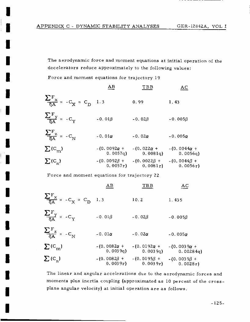
APPENDIX C - DYNAMIC STABILITY ANALYSES CER-l2842A, VOL I I
The aerodynamic f o r c e and moment equations at ini t ia l operation of the
dece lera tors reduce approximately to the following values:
F o r c e and moment equations fo r t ra jec tory 19
AC - - AB TBB
- - - -cx - 1 . 3 0 .99 1.43 c Fx - ‘D w
y= -c -0.01p -0.02p - 0.005p Y CF
qA
-0.OlQ -0.02Q -0 . 0 0 5 ~ - cN CFZ - =
qA
- (0. 0 0 9 2 ~ t - ( 0 . 0 2 2 ~ t - ( O . 0 0 4 4 ~ t 0. 0057q) 0. 0081q) 0. 0056q)
0. 0057r) 0. 0081r) 0. 0056r) - ( O . 0092p t - ( O . 0022p t - ( O . 00446 t
F o r c e and moment equations fo r t ra jec tory 22
AC - AB TBB -
- - - -cx - - CD 1 .3 10 .2 1 .435 c FX
qA
-0 .01p - 0 . ozp -0 . 005p
- 0 . O l Q -0 .02Q -0 . 0 0 5 ~ c - - FZ - -cN w - ( O . 0082Q + - ( O . 0 1 9 2 ~ t - ( O . 0 0 3 9 ~ t
0. 0039q) 0. 0039q) 0. 00284q)
0. 0039r) 0. 0039r) 0 . 0028r) - ( O . 0082p t - ( O . 0195p t - (O. 0039p t
The l inea r and angular accelerations due to the aerodynamic forces and
moments plus iner t ia coupling (approximated as 10 percent of the c r o s s -
plane angular velocity) a t init ial operation a r e as follows.
- 125-

APPENDIX c - DYNAMIC STABILITY A ~ A L Y S E S GER- 12842A, VOL I
L inea r and angular acce lera t ions f o r t r a j ec to ry 19
AB - .. x = - 8 4 . 5
9 = -0 .656
z = - 0 . 6 5 ~ ..
b = 0
6 = - 0 . 8 3 7 ~ - 0 . 519s - 0. l r
5 = -0 .8376 - 0. 5191- - 0. l q
TBB .. x = -84. 1
t; = - 1 . 7 6
r ; = o
.. z = -1 .7Q
4 = - 3 . 2 3 ~ - 1 . 1 9 s - 0. l r $ = -3 .236 - 1. 1 9 r - 0. l q
.. x = - 8 4 . 4
= -0 .2956 .. z = - 0 . 2 9 5 ~
r ; = o 4 = - 0 . 3 7 4 ~ - O.476q - 0 . I r
= -0 .3746 - 0 . 4761- - 0 . l q
Linear and angular acce lera t ions fo r t r a j e c t o r y 22
AB - .. x = - 7 5 . 4
y = - 0 . 586 z = - 0 . 5 8 ~
..
.. b = o 4 = -0 . 5 4 1 ~ - 0 . 257q - 0. l r
= -0 .5416 - 0 . 2571- - 0 . l q
- 126-
/

APPENDIX C - DYNAMIC STABILITY ANALYSES GER-12842AJ VOL I
TBB
e 0
x = - 7 5 . 4
y = -1 .48p I .
.. z = - 1 . 4 8 ~
b = o 4 = - 2 . 0 6 5 ~ ~ - 0. 414q - 0. l r
= -2.065p - 0.4141- - 0. Iq
.. x = -74 .6
y = - 0 . 2 6 6
z = - 0 . 2 6 ~
p = o
.. 0.
0
4 = - 0 . 2 5 3 ~ - 0 . 185q - 0 . l r
E = -0 .253p - 0.1851- - 0 . l q
Refer now to F igures 27 and 28 of this volume.
s i s , i t is shown by inspection of the f igures and the reduced equations
above that the difference in the angular osci l la t ion cha rac t e r i s t ics
among the th ree at tached dece lera tor configurations is p r i m a r i l y af-
fected by the magnitude of the s t a t i c aerodynamic fo rce coefficient and
the s t a t i c s tabi l i ty marg in .
pandable a t tached decelerator configuration is of p r i m a r y impor tance tG
e n s u r e des i r ab le dynamic stabil i ty cha rac t e r i s t i c s fo r a specif ic t e r -
mina l des cent per formance .
tion of the osci l la t ion r a t e cha rac t e r i s t i c s for each configuration.
value fo r the damping factor (Cm
nea r ly the s a m e for each configuration ( s e e I tem 28, Tables A-I11 and
A-XI of Appendix A). motion a t ini t ia l operat ion where the configuration geometry p a r a m e t e r s
a r e introduced, the effect of the dece le ra to r geometry is substant ia l .
In t e r m s of the analy-
That i s , the s i z e and geometry of the ex-
This is fu r the r emphasized by cons idera-
The -t Cm,) is for p rac t i ca l purposes
9 CY
However, upon reduction of the equations of
Again, consider ing the above reduced dynamic motion equations fo r each
-127-

APPENDIX C - DYNAMIC STABILITY ANALYSES GER-12842AJ VOL I
of the attached dece le ra to r configurations a t init ial operation, the deg ree
of accu racy may be approximated i n basing the previous weight ana lyses
on the assumptions that adequate stabil i ty would ex is t and that t he re would
be l i t t le dynamic interact ion with s t ress -weight requi rements .
t ranslat ional decelerat ion load along the longitudinal axis on the com-
posite entry-body dece lera tor is approximated as follows:
The total
where
g e = ea r th g ' s (32. 2 f t /sec/sec) ,
k = t r a n s v e r s e radius of gyrat ion of composi te
s y s t e m (from I tem 2 1 , Tables A-111 and A-XI
of Appendix A),
q and r = maximum values from F igures 2 7 and 28.
The composite s y s t e m l a t e ra l acce le ra t ion is approximated as :
Conservatively, the composite max imum g ' s can b e approximated as:
The following values a re the equivalent ea r th -g loads acting on the s y s t e m
for each of the at tached dece le ra to r configurations at ini t ia l operat ion f o r
t r a j ec to r i e s 19 and 2 2 :
- 128-

APPENDIX C - DYNAMIC STABILITY ANALYSES GER-l2842A, VOL I
Ear th-g loads for t ra jectory 1 9
TBB AC - - AB - NI - 2 . 6 9 - 2 . 7 2 - 2 . 6 8
x , 9, r
Net e * , -1. 13 - 3 . 4 1 - 0 . 5 2 Y, z, g, r
Ntot -2 . 92 - 4 . 3 5 - 2 . 7 2
Ear th-g loads for t ra jectory 22
TBB AC - AB - N,. - 2 . 4 1 - 2 . 4 4 - 2 . 3 7
x , q, r
N.0 t t - 0 . 6 1 - 2 . 2 4 - 0 . 3 6 y, z, 4, ;.
Ntot -2 . 48 - 3 . 3 1 -2 . 4
Compare , now, the above tabulated values of g-loads with I t em 15 in
Table IV of this s u m m a r y report .
tucked-back BALLUTE for t ra jectory 19) that basing the strength-weight
requi rements of the dece lera tors on quasi- s ta t ic design s t rength, load,
and safety fac tors will, in general , tend to be conservative a s compared
to the max imum loads predicted by the dynamic analysis .
It is seen (with exception of the
This t rend i s on lyas f a r a s the attached dece lera tors a r e concerned. This
observat ion mus t , of course, a l s o be t empered in light of the a c c u r a c y
of the assumpt ions and approximations made throughout the p a r a m e t r i c
study. On the bas i s of previous engineering design experience and ap-
plication, i t is considered that the indicated t rends a r e valid.
4. RESULTS FOR TRAILING CONFIGURATION
As descr ibed in Appendix B of Volume 11, the trail ing dece lera tor i s
attached to the forebody through a suspension s y s t e m a s s u m e d to be
rigid. The confluence point is defined as the in te rsec t ion of the suspension
-129 -

APPENDIX C - DYNAMIC STABILITY ANALYSES GER- 1 2 8 4 2 4 VOL I
s y s t e m and r i s e r .
me t r i ca l relationship with respec t to the forebody r ega rd le s s of the
motion of e i ther the forebody o r t ra i l ing dece lera tor .
t rea ted as essentially a rigid rod f r e e to pivot a t any angle and in any
plane a t the confluence point.
In the ana lys i s , this point re ta ins a constant geo-
The r i s e r l ine is
The dece lera tor attached to the end of the r i s e r a l s o is defined a s r e -
taining a f ixed geometr ica l re la t ionship with the r i s e r (essent ia l ly a
rigid sphe re a t the end of a rigid rod f r e e to pivot a t the confluence
point).
having two degrees of f r eedom about the confluence point.
is influenced by the aerodynamic lift and s ide- force as a function of
angle of attack and yaw ( i . - e. , angular displacement of the r i s e r ) a s wel l
a s the d rag force and mass cha rac t e r i s t i c s of the dece lera tor . The spin
of the forebody i s not considered to affect the dece le ra to r motion as far
a s rotational, iner t ia l , and aerodynamic effects a r e concerned.
Thus, the analysis has neglected any consideration of i ne r t i a l o r a e r o -
dynamic coupling in descr ibing the motion of the t ra i l ing dece le ra to r .
The effect of the t ra i l ing dece lera tor motion and loads on the forebody
motion i s assumed to be t ransmi t ted as a tension f o r c e through the r i s e r
to the fixed confluence point.
Thus, fo r this p r o g r a m the motion of the composi te forebody and t r a i l -
ing decelerator has been descr ibed by the e ight -degree-of - f reedom
formulat ion presented in Appendix B of Volume 11.
The motion of the t ra i l ing dece lera tor and r i s e r is descr ibed as
This motion
Refer r ing now to F igures 27 and 28 and F igures C - 1 through C-6 of this
appendix fo r the t ra i l ing dece lera tor , i t is shown that the p re sen t ma the -
mat ica l model desc r ibes a n apparent coupling effect and resonance be-
tween rolling velocity and angular att i tude. This coupling causes the
composi te capsule motion to diverge to l a rge a t tack , yaw, and coning
angles f o r t ra jec tor ies 1 9 and 22. F igures C- 1 through C-6 have been developed f rom additional computer runs f o r the s a m e capsule/ t ra i l ing
dece lera tor charac te r i s t ics f o r different values of roll ing velocity. The
- 130-

I I
I
I I
1 I I I
1
APPENDIX C - DYNAMIC STABILITY ANALYSES GER-l2842A, VOL I
I
0 0 0 - X
I- W W IL
W 0 3
I- -I
- t-
a
7
61
51
4
3
21
11
C
C- 1 - Decelera tor Oscillation Charac te r i s t ics f o r Trai l ing BALLUTE (Atmosphere VM7; Trajectory 22; p = 0 . 0 rad/sec)
- P A Y L O A D
t - ---- D E C E L E R A T O R
p 0.0 RAD’SEC
PITCH-YAW DAMPING = -S.Z/RAD I
5 10 15 2 0 25
A N G L E OF A T T A C K (DEGREES)
-131-

APPENDIX C - DYNAMIC STABILITY ANALYSES GER-l2842A, VOL I
0 0 0 o i - 0 N 0 m 0 U 0 VI r. (D
(0001 x 1333) 3 a n i i n v
--r K
2
E 0 m 0 U 0 * 0 0
C-2 - Decelerator Oscil lation Charac t e r i s t i c s f o r Trai l ing BALLUTE (Atmosphere VM7; Tra j ec to ry 22; p = 0. 5 rad /sec)

1 I I
APPENDIX C - DYNAMIC STABILITY ANALYSES GER-l2842A, VOL I
7 0
60
50
40
30
20
X
w 0 3 I- t -
- P A Y L O A D
-- - D E C E L E R A T O R I
I p 0.75 R A W S E C
PITCH-YAW DAMPING = -5 ,2 /RAD
5 10 1 5 2 0 25 ANGLE OF A T T A C K (DEGREES)
C-3 - Decelera tor Oscillation Charac te r i s t ics for Trail ing BALLUTE (Atmosphere VM7; Tra jec tory 2 2 ; p = 0. 75 rad/sec)
- 1 3 3 -

APPENDIX C - DYNAMIC STABILITY ANALYSES G E R - 12842A, VOL I
C - 4 - Decelerator Oscil lation Charac t e r i s t i c s f o r Tra i l ing BALLUTE (Atmosphere VM7; Tra j ec to ry 2 2 ; p = 1. 0 rad /sec)
- 134-
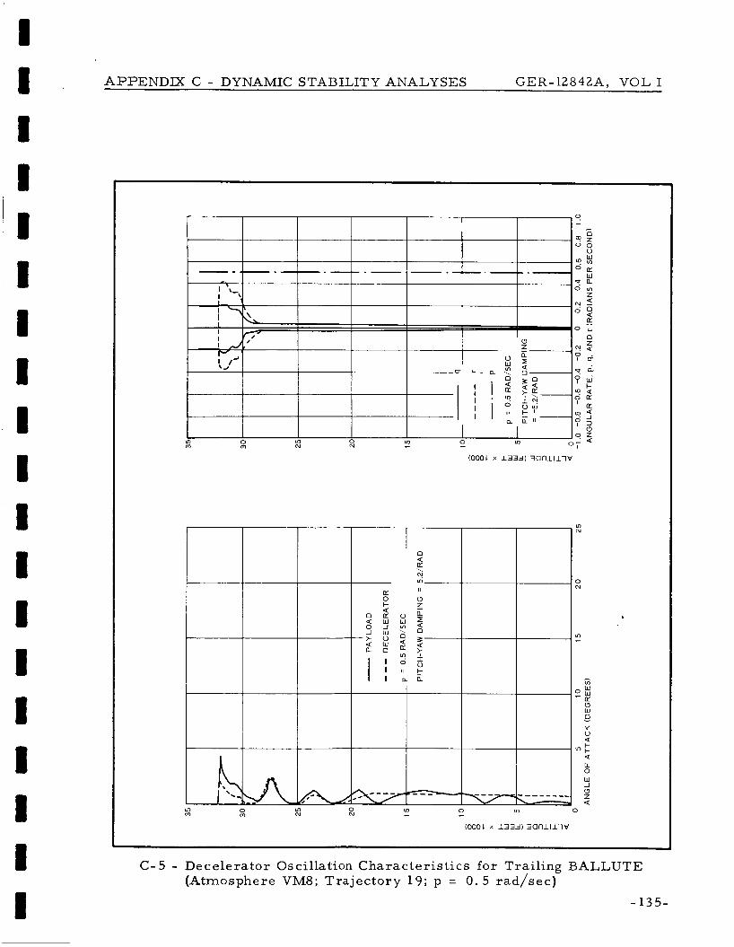
APPENDIX C - DYNAMIC STABILITY ANALYSES CER- l2842A, VOL I
h I '\.. Lo N Lo 0
m m
0 Q E \ "! Lo-
I
Lo -
LL 0 W J 0 z Q
>
C- 5 - Decelera tor Oscillation Charac te r i s t ics for Trail ing BALLUTE (Atmosphere VM8; Tra jec tory 19; p = 0 .5 rad /sec)
- 135-

APPENDIX C - DYNAMIC STABILITY ANALYSES G E R - 12842A, VOL I
,
,
- 136-
C-6 - Decelerator Oscil lation Charac t e r i s t i c s f o r Trai l ing BALLUTE (Atmosphere VM8; Tra j ec to ry 19; p = 1. 0 rad /sec)
APPENDIX C - DYNAMIC STABILITY ANALYSES GER- 12842A, VOL I
apparent e f fec t of ro l l coupling on the s y s t e m motion as descr ibed by
the present mathemat ica l model is s t rongly in evidence.
The drag fo rce and moment of the t ra i l ing dece lera tor has the na tu ra l
effect of providing stabilization for the composi te capsule/decelerator
s y s t e m as demonst ra ted by the case for the rolling velocity equal to
ze ro . Additionally, a s shown by the f igures of this appendix, the mag-
nitude of ro l l r a t e is important i n determining whether the s y s t e m wil l
converge to o r diverge f r o m a stable attitude in te rmina l descent . While
the possibil i ty of coupling and resonance is recognized to exis t fo r the
motion of a spining en t ry capsule with a t ra i l ing dece lera tor , Goodyear
Aerospace ' s experience with such applications (including cases of a
spinning forebody) has not exhibited general ly a divergence tendency, a t
l ea s t to the magnitude encountered in this study.
Therefore , the motion of a forebody with a t ra i l ing dece lera tor as p r e s -
ently decr ibed by the eight-degree-of-freedom formulation presented in
Appendix B of Volume I1 is not considered to be a completely adequate
descr ipt ion. The analytical descr ipt ion of the s y s t e m dynamics f o r u s e
of t ra i l ing dece le ra to r s should be studied and evaluated in g r e a t e r de-
tail than encompassed in this p r o g r a m in view of the impor tance for the
r ecove ry and safe landing of p lanetary en t ry vehicles .
5. CONCLUSIONS AND RECOMMENDATIONS
1. The present s ix-degree-of-freedom mathemat ica l
model describing the dynamic motion of composi te
en t ry body and attached expandable dece lera tor con-
figurations is adequate.
of this study, it i s not n e c e s s a r y to include additional
As shown by the r e su l t s
sophisticated p a r a m e t e r s such as kinematic a e r o -
dynamic coupling t e r m s o r non-linear var ia t ion of
coefficients with angular attitude for pre l iminary
p a r a m e t r i c analyses of the dynamic motion cha rac t e r - is t ics .
- 1 3 7 -

APPENDIX C - DYNAMIC STABILITY ANALYSES GER-l2842A, VOL I
2. F o r the ini t ia l conditions established by the speci-
fied J P L ent ry t r a j ec to r i e s for this study c o r r e -
sponding to the t ime of dece lera tor deployment and
operation, the t rans ien t dis t rubance as a resu l t of
dece lera tor deployment does not r e su l t in excessive
angular excursions and r a t e s .
expandable dece lera tor configurations, the t rend is
toward convergence to reasonable magnitudes of an-
gular att i tude and damping of angular r a t e s of motion.
F o r all of the attached
3 . F o r the attached expandable dece lera tor configura-
t ions, the magnitude of the s ta t ic n o r m a l force co-
efficient and s ta t ic m a r g i n of stabil i ty (center of p r e s -
s u r e ) , which a r e indicative of the shape of the device
combined with the device s i ze and configuration geo-
m e t r y , profoundly affect the dynamic motion cha rac t e r -
i s t ics and damping of the composi te sys t em.
4. The computer r e su l t s using the p re sen t e ight-degree-
of-freedom formulation descr ibing the s y s t e m dy-
namics fo r a n en t ry capsule and t ra i l ing dece lera tor
point out that kinematic ( rol l -yaw) coupling effects
can r e su l t in angular att i tude and r a t e divergence
when an ini t ia l ro l l r a t e exceeding about 0 . 5 rad /sec
is present a t deployment.
a l so indicate that t he re is resonance , - i. e . , coupling
between the t ra i l ing dece lera tor and en t ry capsule
motion, that causes a pronounced divergence t rend .
The formulation presented in Appendix B of Volume I1
and the computer p r o g r a m have been de termined to
be mathemat ica l ly c o r r e c t and provide a n accu ra t e
descr ipt ion of the s y s t e m mot ion as descr ibed by the
formulat ion.
T h e computer r e su l t s

APPENDIX C - DYNAMIC STABILITY ANALYSES GER-l2842A, VOL I
5. In this event, the p re sen t e ight-degree-of-freedom
mathemat ica l model fo r the en t ry capsule and t r a i l -
ing decelerator does not appea r to be a completely
accu ra t e description of the s y s t e m dynamics.
observation s tems from actual f ree-f l ight experience
of Goodyear Aerospace personnel with s i m i l a r load-
ing environments. Apparently, m o r e sophisticated
f o r m s a r e required to descr ibe the dynamics s u c h a s
r i s e r - l i ne elasticity and additional degrees of f r eedom
to descr ibe confluence point motion, a t l eas t i n the
l a t e ra l planes. A descr ipt ion of the trail ing decel-
e r a t o r motion a t the end of the r i s e r line by two addi-
tional degrees of f r eedom a l so might be des i rab le .
Thus, i t appears that a t l ea s t twelve degrees of f r e e -
dom m a y be necessa ry to adequately descr ibe the
sys t e m dynamics.
Th.is
A survey should be made of pas t f ree-f l ight t ra i l ing
dece lera tor data.
be gathered to es t imate s ta t ic stabil i ty and damping
coefficient derivatives fo r u s e with the dynamic s t a -
bil i ty analyses of t ra i l ing dece lera tor configurations.
More complete information should
- 139-
I I I
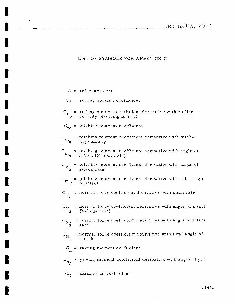
G E R - l 2 8 4 2 A , VOL I
LIST O F SYMBOLS FOR APPENDIX C
A = r e fe rence a r e a
Cl = rolling moment coefficient
Cp = rolling moment coefficient der i p velocity (damping in ro l l )
Cm = pitching moment coefficient
ati e vith rolling
= pitching moment coefficient derivative with pitch- m C q ing velocity
= pitching moment coefficient derivative with angle of a at tack (X-body axis) m C
= pitching moment coefficient derivative with angle of m - C LY at tack r a t e
= pitching moment coefficient derivative with total angle m C p of at tack
CN = norma l f o r c e coefficient derivative with pitch r a t e
9
C = n o r m a l force coefficient derivative with angle of a t tack Na (X-body axis)
C = n o r m a l f o r c e coefficient derivative with angle of a t tack Nci r a t e
C = n o r m a l force coefficient derivative with total angle of N P a t tack
C = yawing moment coefficient n
C = yawing moment coefficient derivative with angle of yaw "0
Cx = axial force coefficient
-141-
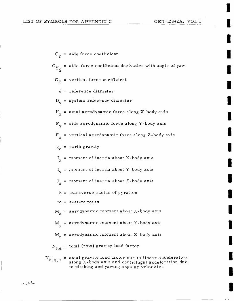
LIST O F SYMBOLS FOR APPENDIX C GER-12842A’ VOL I
-142-
~
Cy = s ide fo rce coefficient
Cy = s ide- force coefficient der ivat ive with angle of yaw
P Cz = ver t i ca l fo rce coefficient
d = r e fe rence d i ame te r
D = s y s t e m re fe rence d i ame te r V
F = axial aerodynamic fo rce along X-body axis X
F = side aerodynamic fo rce along Y-body axis Y
F = ver t ica l aerodynamic f o r c e along Z-body axis Z
= ea r th grav i ty ge
I = moment of iner t ia about X-body axis
I = moment of iner t ia about Y-body axis
X
Y
I = moment of iner t ia about Z-body axis Z
k = t r a n s v e r s e radius of gyration
m = s y s t e m mass
M = aerodynamic moment about X-body axis X
M = aerodynamic moment about Y-body axis Y
M = aerodynamic moment about Z-body axis Z
= t o t a l ( rms) gravi ty load f ac to r Ntot
N.. = axia l g rav i ty load fac tor due to l i nea r acce lera t ion along X-body ax i s and cent r i fuga l acce le ra t ion due t o pitching and yawing angular veloci t ies
x’ q’

I I I I I I I I I I I 1 I 1 I 1 1 1 I
LIST O F SYMBOLS FOR APPENDIX C GER-l2842A, VOL 1
N.. Y,
= t r ansve r se gravity load f ac to r due to l inear acce l - erat ions along Y and Z body ax is and pitching and yawing angular accelerat ions
Z , i , i
p = rolling angular velocity
= rolling angular acce lera t ion
q = pitching angular velocity
= dynamic p res su re
6 = pitching angular accelerat ion
r = yawing angular velocity
G = yawing angular accelerat ion
V = velocity (total)
k = l inear velocity component along X-body axis
x = l inear accelerat ion along X-body axis ..
9 = l inear velocity component along Y-body axis .. y = l inear acceleration along Y-body axis
= l inear velocity component along Z-body axis
.. z = l inear accelerat ion along Z-body axis
CY = angle of attack
& = angle of attack ra te
p = angle of yaw
j = angle of yaw ra t e
AX = center of p re s su re position with respec t to sys tem ‘P center of gravity
= summation of re la ted fac tors or t e r m s
-143-
Recommended