1
Preparation for the 3He Injection Test
11/2007 MIT/BATES
D. Dutta*, H. Gao, M. Busch, Q. Ye, X. Qian, W.
Zheng, X. Zhu (Duke University)
ASU, BU, Caltech, LANL, MIT, MSU, NCSU, SFU
And others in nEDM collaboration
*Mississippi State University.

2
Outline
• Introduction• Magnets• Glassware design• Cryogenics • pNMR & Calibration• Summary

3
The Goal of Injection Test
• 3He, out of ABS, collected within superfluid 4He at 0.3K
• pNMR to demonstrate that polarization loss is acceptable

4
Magnets system
• Superconducting tri-coil– Central axial field uniformity<16ppm
• By Cryomagnetics
– Liquid 4He container • By MIT
• Superconducting solenoid– Ready, to be installed– design of coil support finished
• Conduction cooled» To be made by Boston Univ.
Tri-coil
Solenoid co
il
4545o

5
3He Spin Rotation
• Spin follows the field direction– AFP condition:
• Monte-carlo simulation:– Average spin rotation ~ 3.35±0.30 deg– Polarization ~98.8%
40
0
~ 625 ~ 6 10z Hz f HzB
B
3He trajectory

6
3He Spin Rotation Test at 300K
• Parallel mag. field – FID signal drop
by ~12.11
• Curved mag. field– FID signal drop
by ~11.9
B B
Polarization loss due to curved field is negligible
45o
1.5m

7
Pyrex Collection Cell
• Pyrex collection cell– Glass to copper adaptor
• thermal cycle<20 times – Jacket design works– Coating with Cs ampule
• Started with CsN3/Cs-Spencer coating
» S. Lamoraux and E. Ihloff – Hard to control contamination
• In situ Coating with Cs ampule– Cs port not needed– Space is accessible
» J. Boissevain and M. Busch
10/2006
06/2007
11/2007

8
Coating with CsN3• Hard to know/control
contamination above 400 deg C.
9
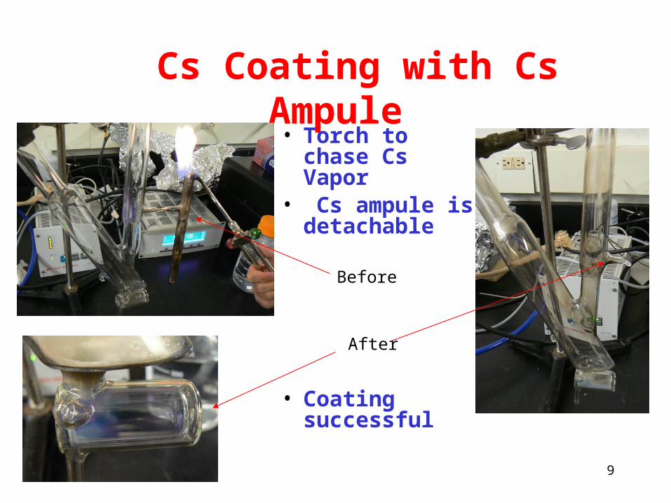
Cs Coating with Cs Ampule
• Torch to chase Cs Vapor
• Cs ampule is detachable
• Coating successful
Before
After

10
Cryogenics
• Filling of 4He– Jacket– 3He collection cell
» J. Boissevain
• Location of temperature sensors– Film burner
11
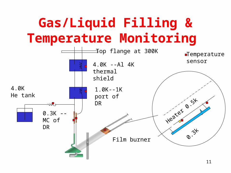
Gas/Liquid Filling & Temperature Monitoring
1.0K--1K port of DR
0.3K --MC of DR
4.0K --Al 4K thermal shield
4.0KHe tank
Top flange at 300K
Film burner
Heater
0.5k
0.3k
Temperaturesensor

12
pNMR for Injection Test
• pNMR setup at Duke– An existing magnet
modified for this test:• 1kG • Uniformity ~ 80mG/cm
– Tank circuit tuned ~ 3.89MHz
– Proton FID signal is observed at room temperature
• Comparable to 3He density during injection test
~1X10¹⁴ polarizedprotons/cc
magnetTank circuit magnet
Tecmag Apollo console
Tank circuit

13
Trying to improve S/N on 1H
• Spin tipping angle at room temp.– RF duration time
• Spin echo signal– For calibration
purpose
• RF shielding– Au plated mylar
• A. Matlachov
FID signal
2
T2 measurement on water sample

14
Inside dewar at 4K
1.5m, 50 ohm coax cable
Single coil setup
21
21
2
( ) 1
(1 ) 50( )Q CpCsL
L Cp Cs
ohm
Tuning of Cs and Cp:

15
Separate RF: Saddle Coil
• Coil design– diameter=2.54cm– length =5cm– angular aperture: 135 deg
• ( not 120 deg, due to big region of interest)
– rung width: 15 deg • Saddle coil increases the
signal size by ~1.4– Disadvantage
• Smaller RF field• Longer pulse duration
– RF heating and T2 limitation

16
Polarization Calibration
• Calibration carried out after injection test
• 0.001 mol of 3He will be filled– ~5x10¹⁵ polarized atoms/cc at
0.5K, 1.2 kG
• 3He /4He gas filling panel is under construction

17
Injection Test Pumping Station
• Volume from MIT
• Going to make a gas handling system

18
Summary
• Magnets are ready, to be assembled with cryostat– Curved field passed spin rotation test
• Cryogenics and collection cell are under fabrication– Coating with Cs ampule
• pNMR system under optimization• Injection test will be carried out
at LANL this winter

19
Thanks!
Recommended