1
Using Directionality in Wireless Routing
Bow-Nan ChengAdvisors:
Dr. Shivkumar KalyanaramanDr. Partha Dutta

2
Motivation
Main Issue: Scalability
Infrastructure / Wireless Mesh Networks
• Characteristics: Fixed, unlimited energy, virtually unlimited processing power• Dynamism – Link Quality• Optimize – High throughput, low latency, balanced load
Mobile Adhoc Networks (MANET)
• Characteristics: Mobile, limited energy• Dynamism – Node mobility + Link Quality• Optimize – Reachability
Sensor Networks• Characteristics: Data-Centric, extreme limited energy• Dynamism – Node State/Status (on/off)• Optimize – Power consumption
Introduction Wireless Mesh Networks Mobile Ad-Hoc Networks Overlay Networks

3
Scaling Networks: OSI Model
1: Physical Layer
4: Transport Layer
3: Network Layer
2: Link Layer
Layers 5-7
Z
C
E
F
H
GA B
A Z
1011010
Physical Layer – Handles transmission of bits through a medium
Link Layer – Manages node-to-node transmissions
Network Layer – Manages routing from end-to-endTransport Layer – Handles reliable transmissions end-to-end
Introduction Wireless Mesh Networks Mobile Ad-Hoc Networks Overlay Networks
Application/Presentation/Session Layers – Deal with the actual programs/data

4
Scaling Networks: Trends in Layer 3
Flood-based Hierarchy/Structured Unstructured/FlatScalable
Mobile Ad hoc /Fixed Wireless Networks
DSR, AODV,TORA, DSDVPartial Flood:OLSR, HSLS
LGF, VRR, GPSR+GLSHierarchical Routing,
Peer to Peer /Overlay Networks
Wired Networks
Gnutella Kazaa, DHT Approaches: CHORD, CAN
Ethernet Routers (between AS)
WSR (Mobicom 07)ORRP (ICNP 06)
SEIZE
Introduction Wireless Mesh Networks Mobile Ad-Hoc Networks Overlay Networks
BubbleStorm (Sigcomm 07)LMS (PODC 05)

5
Trends: Directional Antennas
• Directional Antennas – Capacity Benefits Theoretical Capacity Improvements - factor of 42/sqrt()
where and are the spreads of the sending and receiving transceiver ~ 50x capacity with 8 Interfaces (Yi et al., 2005)
Sector Antennas in Cell Base Stations – Even only 3 sectors increases capacity by 1.714 (Rappaport, 2006)
Directional Antennas – Simulations show 2-3X more capacity (Choudhury et al., 2003)
A’
B’
C’
D’
A
B
C
D
Omni-directional Transmission
A’
B’
C’
D’
A
B
C
D
Directional Transmission
Introduction Wireless Mesh Networks Mobile Ad-Hoc Networks Overlay Networks

6
Trends: Hybrid FSO/THz FSO/RF MANETs• Current RF-based Ad Hoc Networks:
802.1x with omni-directional RF antennas
High-power – typically the most power consuming parts of laptops
Low bandwidth – typically the bottleneck link in the chain
Error-prone, high lossesFree-Space-Optical
(FSO) Communications
Mobile Ad Hoc Networking
• High bandwidth• Low power• Dense spatial reuse• License-free band of operation
• Mobile communication• Auto-configuration
Free-Space-OpticalAd Hoc Networks
• Spatial reuse and angular diversity in nodes• Low power and secure• Electronic auto-alignment• Optical auto-configuration (switching, routing)• Interdisciplinary, cross-layer design
Introduction Wireless Mesh Networks Mobile Ad-Hoc Networks Overlay Networks

7
Research Objectives• Wireless Mesh Context
Can directionality be used to address issues with scalability at higher throughput in layer 3 routing?
• Mobile Ad Hoc Context Can directionality be used to address issues with
high mobility and throughput in layer 3 routing?• Overlay Network Context
Can directionality be used to scale flat, unstructured networks?
Introduction Wireless Mesh Networks Mobile Ad-Hoc Networks Overlay Networks

8
By removing position
information, can we still efficiently
route packets?
Orthogonal Rendezvous Routing Protocol
L3: Geographic Routing using Node IDs (eg. GPSR, TBF etc.)
L2: ID to Location Mapping (eg. GHT, GLS etc.)
L1: Node Localization
ORRP
N/A
Issues in Position-based Schemes
S
N
W E
(0,4)
(4,6)
(5,1)
(8,5)
(12,3)
(15,5)S
D
D(X,Y)? ?
Introduction Wireless Mesh Networks Mobile Ad-Hoc Networks Overlay Networks

9
ORRP Big Picture
Up to 69%
A
98%
B
180o
Orthogonal RendezvousRouting Protocol
ST
ORRP Primitive1: Local sense of directionleads to ability to forwardpackets in opposite directions
2: Forwarding alongOrthogonal lines hasa high chance of intersection in area
Introduction Wireless Mesh Networks Mobile Ad-Hoc Networks Overlay Networks

10
ORRP Design Considerations• Considerations:
High probability of connectivity without position information [Reachability]
Scalability O(N3/2) total state information maintained. (O(N1/2) per node state information)
Even distribution of state information leading to no single point of failure [State Complexity]
Handles voids and sparse networks• Trade-offs
Path Stretch Probabilistic Reachability
Introduction Wireless Mesh Networks Mobile Ad-Hoc Networks Overlay Networks

11
ORRP Proactive and Reactive Elements
Node B Fwd Table
Dest Next Hops
A A 1120o
NorthNorth
North
North
North
Node F Fwd Table
Dest Next Hops
A B 2
Node C Fwd Table
Dest Next Hops Dir
A F 3 120o
D D 1 230o
230o
1. ORRP Announcements (Proactive) – Generates Rendezvous-to-Destination Routes2. ORRP Route Request (RREQ) Packets (Reactive) – Generates Source-to-Rendezvous Rts3. ORRP Route Reply (RREP) Packets (Reactive)4. Data path after route generation
D
CFBA
Introduction Wireless Mesh Networks Mobile Ad-Hoc Networks Overlay Networks
A to D

12
Reachability Numerical AnalysisP{unreachable} =
P{intersections not in rectangle}
4 Possible Intersection Points
1
2
3
98.3% 99.75%
57%
67.7%
Probability of Unreach highest at perimeters and corners
NS2 Simulations with MAM show
around 92% reachability
Introduction Wireless Mesh Networks Mobile Ad-Hoc Networks Overlay Networks

13
Path Stretch Analysis
Average Stretch for various topologies
• Square Topology – 1.255• Circular Topology – 1.15• 25 X 4 Rectangular – 3.24• Expected Stretch – 1.125
x = 1.255 x = 1.15
x = 3.24
Introduction Wireless Mesh Networks Mobile Ad-Hoc Networks Overlay Networks
14
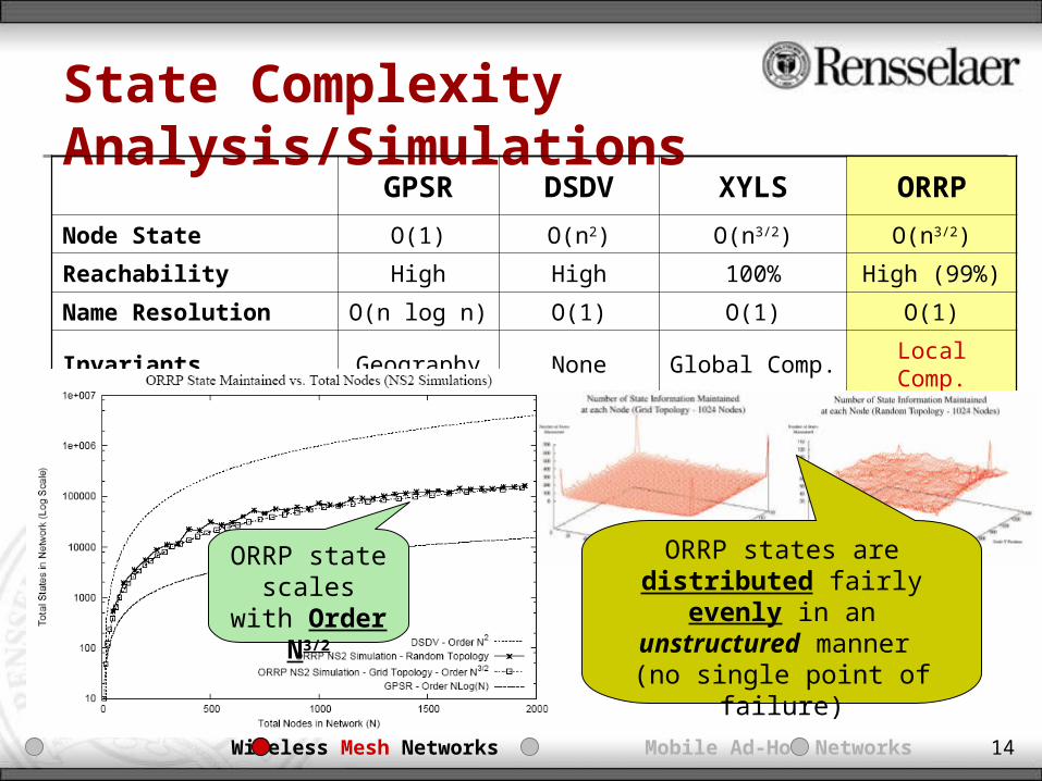
State Complexity Analysis/SimulationsGPSR DSDV XYLS ORRP
Node State O(1) O(n2) O(n3/2) O(n3/2)
Reachability High High 100% High (99%)
Name Resolution O(n log n) O(1) O(1) O(1)
Invariants Geography None Global Comp. Local Comp.
ORRP state scales with Order N3/2
ORRP states are distributed fairly evenly
in an unstructured manner
(no single point of failure)
Introduction Wireless Mesh Networks Mobile Ad-Hoc Networks Overlay Networks

15
ORRP: Simulation Results Summary• Base Case
Reach – 99% for Square topologies, 92% for Rectangular topologies (MAM helped)
Path Stretch – Roughly 1.2 Goodput – About 30x more aggregate network goodput than AODV, 10x more
aggregate network goodput than OLSR and 35x more aggregate network goodput than GPSR with GLS (due to better usage of medium)
• Network Voids Average path length fairly constant (Reach and State not different)
• Additional Lines Reach/Path Stretch – All showed large gains from 1 to 2 lines but diminishing
returns thereafter Goodput – Higher average network throughput with additional lines (better
paths and higher reach) but not by much• Varying Number of Interfaces
Significant increase in reachability from 4 to 8 interfaces, but gains trail off
Introduction Wireless Mesh Networks Mobile Ad-Hoc Networks Overlay Networks

16
ORRP: Summary• ORRP achieves high reachability in random topologies• ORRP achieves O(N3/2) state maintenance – scalable even
with flat, unstructured routing• ORRP achieves low path stretch (Tradeoff for connectivity
under relaxed information is very small!)• ORRP achieves roughly 30X in aggregate network goodput
compared to AODV, 10X the aggregate network goodput compared to OLSR, and 35X the aggregate network goodput compared to GPSR with GLS.
Relevant Papers• B. Cheng, M. Yuksel, and S. Kalyanaraman, Rendezvous-based Directional Routing: A Performance Analysis, In Proceedings of IEEE International
Conference on Broadband Communications, Networks, and Systems (BROADNETS), Raleigh, NC, September 2007. (invited paper) • B. Cheng, M. Yuksel, and S. Kalyanaraman, Directional Routing for Wireless Mesh Networks: A Performance Evaluation, Proceedings of IEEE Workshop
on Local and Metropolitan Area Networks (LANMAN), Princeton, NJ, June 2007. • B. Cheng, M. Yuksel, and S. Kalyanaraman, Orthogonal Rendezvous Routing Protocol for Wireless Mesh Networks, Proceedings of IEEE International
Conference on Network Protocols (ICNP), pages 106-115, Santa Barbara, Nov 2006.
Introduction Wireless Mesh Networks Mobile Ad-Hoc Networks Overlay Networks

17
Mobile-ORRP (MORRP) Motivation
A
B
98%
ORRP• High reach, O(N3/2) State
complexity, Low path stretch, high goodput, unstructured
• BUT.. What happens with mobility?
• Issues with Mobility Interface Handoff
Issue Nodes closer
seemingly incur MORE dynamism than nodes farther away
R
~1.2 vs. SP
65%55%
42%
IncreasingMobility
Introduction Wireless Mesh Networks Mobile Ad-Hoc Networks Overlay Networks

18
MORRP Introduction
A
B
What can we do?• Replace intersection
point with intersection region.
• Shift directions of send based on local movement information
• Route packets probabilistically rather than based on rigid next-hop paths. (No need for route maintenance!)
• Solution: a NEW kind of routing table: Directional Routing Table (DRT)
R
Introduction Wireless Mesh Networks Mobile Ad-Hoc Networks Overlay Networks

19
J
K
LM
IH
O P
S
N
R
Q
F
C
G
E
A
B
MORRP Basic Example
Original Path
Original Path
OriginalDirection ()
NewDirection()
R: Near Field DRTRegion of Influence
D: Near Field DRTRegion of Influence
S: Near Field DRTRegion of Influence
D
D’
D
R
R’
R
Introduction Wireless Mesh Networks Mobile Ad-Hoc Networks Overlay Networks
S
1. Proactive Element – Generates Rendezvous to Dest Paths2. Reactive Element – Generates Source to Rendezvous Paths

20
The Directional Routing Table
DestID
NextHop
DestID
NextHop
BeamID
Dest IDs(% of Certainty)
BeamID
BCD:Z
BBZ:Z
BCD:Z
BBZ:Z
113:3
B(90%), C(30%).Z(90%), D(40%).
1234
BC
ZD
A4
1
2
3
Routing Table RT w/ Beam ID Directional RT (DRT)
ID ID ID set of IDs Set of IDs set of IDs
Routing Tables viewed from Node A
• Destination ID % of Certainties for each Beam ID stored within a Decaying Bloom Filter
• Bloom Filter – A space-efficient probabilistic data structure that is used to test whether an element is a member of a set. Consist of a bit array and a set of k linearly independent hash functions Storage: IDs are hashed to each of the k hash functions stores a ``1’’ in
position in the bit array for each hash function. Search: IDs are hashed through each of the k hash functions if all positions
have a “1”, then the ID is in the set. Otherwise, the ID is not in the set
Introduction Wireless Mesh Networks Mobile Ad-Hoc Networks Overlay Networks

21
DRT: Decaying Bloom Filter Primer
0 0 0 0 0 0 0 0 0 0 0 0 0 0 0 0 0 0 0 0 0 0 0 0 0 0 0 0 00 1 2 3 4 5 6 7 8 9 10 11 12 13 14 15 16 17 18 19 20 21 22 23 24 25 26 27 28
h1(x) = (x2 + 20) % 32 h2(x) = x % 32 h3(x) = (x + 5) % 32 h4(x) = (x3 + 25) % 32h1(1) = 21 h2(1) = 1 h3(1) = 6 h4(1) = 26
029
030
031
ID: 1 ID: 2
h1(2) = 24 h2(2) = 2 h3(2) = 7 h4(2) = 1
1 1 1 1 1 1 1
ID: 6
h1(6) = 24 h2(6) = 6 h3(6) = 11 h4(6) = 17
Search ID 1 – 4 of 4 bits match (IN set)Search ID 6 – 2 of 4 bit match (Not in set)
Traditional Bloom Filter
Decaying Bloom Filter (DBF)Search ID 1 – 4 of 4 bits match (100% chance in set)Search ID 6 – 2 of 4 bit match (50% chance in set)
Introduction Wireless Mesh Networks Mobile Ad-Hoc Networks Overlay Networks
32 Bit Array:
4 HashFuncs:
A 1
234
5
67 8
Dest Prob.(DBF)
BeamID
0010..10000000..10010011..01010101..10010010..00000000..00010011..10110111..1001
12345678
DRTWhat policiesFor decayingbits can we employ?

22
4
1
2
3
DRT Inter-Node Decay
Decay 50% of Bits
DNoise
CLow Info
BMed Info
AStrong InfoS
0 0 1 0 0 1 0 0 0 0 0 1 0 0 0 0 …
0 0 0 0 0 1 0 0 0 0 0 0 0 1 0 0 …
0 1 0 0 1 0 0 0 1 0 0 0 0 0 0 1 …
0 0 1 0 0 0 1 0 0 0 1 0 0 1 0 0 …
DRT at Node ABEAM ID: 1
BEAM ID: 2
BEAM ID: 3
BEAM ID: 4
Bitwise-OR0 1 1 0 1 1 1 0 1 0 1 1 0 1 0 1 … Merged DBF (Update DBF)
0 0 1 0 0 1 0 0 1 0 0 1 0 0 0 1 … Decayed DBF (50% bits dropped)
CB
A
0 0 1 1 0 1 1 0 1 0 0 1 0 1 0 1 …
My ID (A)
h1(x), h2(x), …, hn(x)
Broadcasted by A to all Neighbors
B is now 100% sure A is 1 hop away while only 50% sure C can be reached through sending out interface 1
Introduction Wireless Mesh Networks Mobile Ad-Hoc Networks Overlay Networks
23
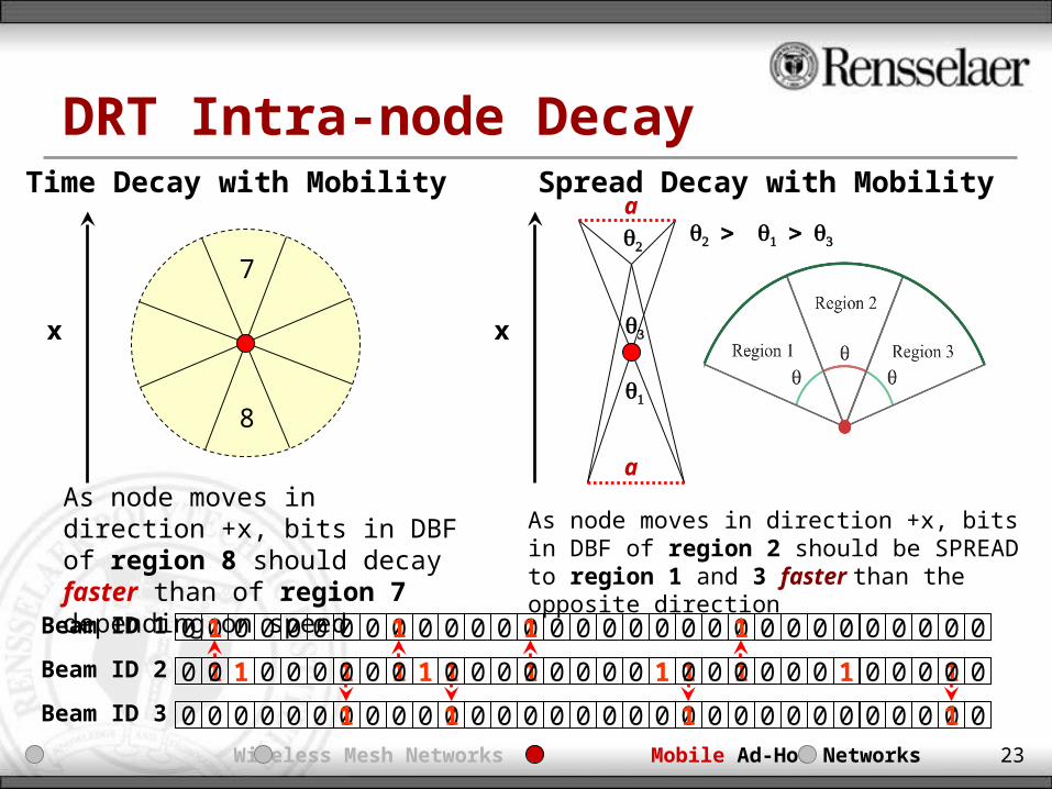
DRT Intra-node DecayTime Decay with Mobility Spread Decay with Mobility
7
8
x
As node moves in direction +x, bits in DBF of region 8 should decay faster than of region 7 depending on speed
As node moves in direction +x, bits in DBF of region 2 should be SPREAD to region 1 and 3 faster than the opposite direction
a
a
x
Beam ID 1
Beam ID 2
Beam ID 3
Introduction Wireless Mesh Networks Mobile Ad-Hoc Networks Overlay Networks
0 0 0 0 0 0 0 0 0 0 0 0 0 0 0 0 0 00 0 0 0 0 0 0 0 0 0 0 0 0
0 1 0 0 0 0 1 0 0 0 0 0 0 1 0 0 0 0 1 0 0 01 1 1 1 1 1 1 1 0
0 0 0 0 0 0 0 0 0 0 0 0 0 0 0 0 0 0 0 0 0 0 0 0 0 00 0 0 0 011 1 1
1 1 1 1
0 0 0 0 00 00

24
N
N
N
N
N
N
N N
N
N
N
N
N
N
N
N
N
N
N
MORRP Fields of Operation
• Near Field Operation Uses “Near Field DRT” to match for
nodes 2-3 hops away• Far Field Operation
RREQ/RREP much like ORRP except nodes along path store info in “Far-Field DRT”
S R
D
Introduction Wireless Mesh Networks Mobile Ad-Hoc Networks Overlay Networks

25
Performance Evaluation of MORRP• Metrics Evaluated
Reachability – Percentage of nodes reachable by each node in network (Hypothesis: high reachability)
Delivery Success – Percentage of packets successfully delivered network-wide Scalability – The total state control packets flooding the network (Hypothesis:
higher than ORRP but lower than current protocols out there) Average Path Length End to End Delay (Latency) Aggregate Network Goodput
• Scenarios Evaluated Affect of Time Decay Factor on Reach for various mobility speeds Affect of Distance Decay Factor on Reach for various mobility speeds Affect of NF and FF Threshold on Reach for various mobility speeds Evaluation of metrics vs. AODV (reactive), OLSR (proactive), GPSR with GLS
(position-based), and ORRP under various node velocities, densities, topology-sizes, transmission rates.
Evaluation of metrics vs. AODV and OLSR modified to support directional antennas.
Introduction Wireless Mesh Networks Mobile Ad-Hoc Networks Overlay Networks

26
MORRP: Aggregate Goodput Results• Aggregate Network Goodput vs.
Traditional Routing Protocols MORRP achieves from 10-14X the
goodput of AODV, OLSR, and GPSR w/ GLS with an omni-directional antenna
Gains come from the move toward directional antennas (more efficient medium usage)
• Aggregate Network Goodput vs. AODV and OLSR modified with directional antennas MORRP achieves about 15-20%
increase in goodput vs. OLSR with multiple directional antennas
Gains come from using directionality more efficiently
Introduction Wireless Mesh Networks Mobile Ad-Hoc Networks Overlay Networks

27
MORRP: Simulations Summary• MORRP achieves high reachability (93% in mid-sized, 1300x1300m2
and 87% in large-sized, 2000x2000 m2 topologies) with high mobility (30m/s).
• With sparser and larger networks, MORRP performs fairly poorly (83% reach) suggesting additional research into proper DRT tuning is required.
• In lightly loaded networks, MORRP end-to-end latency is double of OLSR and about 7x smaller than AODV and 40x less than GPSR w/ GLS
• MORRP scales well by minimizing control packets sent• MORRP yields over 10-14X the aggregate network throughput
compared to traditional routing protocols with one omnidirectional interface gains from using directional interfaces
• MORRP yields over 15-20% the aggregate network goodput compared to traditional routing protocols modified with 8 directional interfaces gains from using directionality constructively
Introduction Wireless Mesh Networks Mobile Ad-Hoc Networks Overlay Networks

28
MORRP: Key Contributions• The Directional Routing Table
A replacement for traditional routing tables that routes based on probabilistic hints
Gives a basic building block for using directionality to overcome issues with high mobility in MANET and DTNs
• Using directionality in layer 3 to solve the issues caused by high mobility in MANETs
• MORRP achieves high reachability (87% - 93%) in high mobility (30m/s)• MORRP scales well by minimizing control packets sent• MORRP shows that high reach can be achieved in probabilistic routing
without the need to frequently disseminate node position information.• MORRP yields high aggregate network goodput with the gains coming not
only from utilizing directional antennas, but utilizing the concept of directionality itself.
• MORRP is scalable and routes successfully with more relaxed requirements (No need for coordinate space embedding)
Relevant Papers• B. Cheng, M. Yuksel, and S. Kalyanaraman, Using Directionality in Wireless Routing, Under Review in IEEE International Conference on Mobile Ad-hoc and
Sensor Systems (MASS) 2008.
Introduction Wireless Mesh Networks Mobile Ad-Hoc Networks Overlay Networks
29
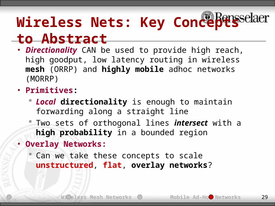
Wireless Nets: Key Concepts to Abstract• Directionality CAN be used to provide high reach, high
goodput, low latency routing in wireless mesh (ORRP) and highly mobile adhoc networks (MORRP)
• Primitives: Local directionality is enough to maintain forwarding along
a straight line Two sets of orthogonal lines intersect with a high
probability in a bounded region• Overlay Networks:
Can we take these concepts to scale unstructured, flat, overlay networks?
Introduction Wireless Mesh Networks Mobile Ad-Hoc Networks Overlay Networks

30
Virtual Direction Routing Introduction• Structured vs. Unstructured Overlay Networks
Unstructured P2P systems make little or no requirement on how overlay topologies are established and are easy to build and robust to churn
• Typical Search Technique (Unstructured Networks) Flooding / Normalized Flooding
• High Reach• Low path stretch• Not scalable
Random Walk• Need high TTL for high reach• Long paths• Scalable, but hard to find rare objects
• Virtual Direction Routing Globally consistent sense of direction (west is always
west) Scalable interface to neighbor mapping Routing can be done similarly to ORRP
• Focus (for now) Small world approximations
Random Walk
Virtual DirectionRouting
Flooding
Normalized Flooding
Introduction Wireless Mesh Networks Mobile Ad-Hoc Networks Overlay Networks

31
VDR: Neighbor to Virtual Interface Map
• Neighbors are either physical neighbors connected by interfaces or neighbors under a certain RTT latency away (logical neighbors)
• Neighbor to Virtual Interface Mapping Each neighbor ID is hashed to 160 bit IDs using SHA-1 (to standardize small or
large IDs) The virtual interface assigned to the neighbor is a function of its hashed ID
(Hashed ID % number of virtual interfaces)
1
10
26
30
15687
10
12
3
4
5 6
8 Virtual Interfaces30 % 8 = 6
15 % 8 = 710 % 8 = 2
26 % 8 = 268 % 8 = 4
68
15
26
30
10
Introduction Wireless Mesh Networks Mobile Ad-Hoc Networks Overlay Networks
Example: Neighbor IDs used Instead Of SHA-1 Hashes

32
VDR: State Seeding and Route Request|10 – 1| = 9|26 – 1| = 25
|5 – 1| = 4|13 – 1| = 12
|14 – 1| = 13|22 – 1| = 21Ex: Seed Source: Node 1
State Seeding – State info forwarded in orthogonal directions, biasing packets toward IDs that are closer to SOURCE ID. Packets are forwarded in virtual straight lines.
100
12
3
4
5 6
7
1
67
513
2868
10
12
3
4
5 6
7
1026
30
15
48
130
12
3
4
5 6
7
38
10
6
|10 – 12| = 2|26 – 12| = 15
|5 – 12| = 7|13 – 12| = 1
|6 – 12| = 6|38 – 12| = 26
Ex: Route Request: Node 12RREQ Source: Node 1
Route Request – RREQ packets are forwarded in orthogonal directions, biasing packets towards REQUESTED ID
0
12
3
4
5 6
7
26
30
1568
48
1
1010
100
12
3
4
5 6
7
1
67
13
28
55
50
12
3
4
5 6
7
55
10
221414
Introduction Wireless Mesh Networks Mobile Ad-Hoc Networks Overlay Networks
10
136

33
VDR: Simulation Parameters
26
5
38
68
48
3010
136
12
2
46
1
RREQ: Node 12
Rendezvous Node
VDR Route RequestVirtual View
Seed Path
RREQ Path
RREP Path
Flooding
Random Walk
VDR – Random NB Send (VDR-R)
Virtual DirectionRouting
Normalized Flooding
Random Walk Routing (RWR)
• Simulation of VDR vs. RWR, VDR-R VDR-R: VDR with random neighbor forwarding (no biasing) RWR: Data is seeded in 4 random walks and 4 walkers are sent
for search• PeerSim – 50,000 Nodes, Static + Dynamic Network
Reach Probability – High (98% w/ TTL of 100) Average Path Stretch – High (16) State and Load Spread – Not evenly distributed
Introduction Wireless Mesh Networks Mobile Ad-Hoc Networks Overlay Networks
34
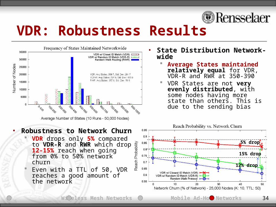
VDR: Robustness Results
5% drop
15% drop
12% drop
• State Distribution Network-wide Average States maintained
relatively equal for VDR, VDR-R and RWR at 350-390
VDR States are not very evenly distributed, with some nodes having more state than others. This is due to the sending bias
• Robustness to Network Churn VDR drops only 5% compared to
VDR-R and RWR which drop 12-15% reach when going from 0% to 50% network churn
Even with a TTL of 50, VDR reaches a good amount of the network
Introduction Wireless Mesh Networks Mobile Ad-Hoc Networks Overlay Networks

35
VDR: Key Contributions• Introduction of the concept of Virtual Directions to eliminate
need for structure (coordinate space, DHT structures) to scale flat, unstructured overlay networks
• A flat, highly scalable, and resilient to churn routing algorithm for overlay networks
• VDR provides high reach (98% even only for a TTL of 100 in a 50,000 node network)
• VDR drops only 2-5% going from 0% churn to 50% churn
Relevant Papers• B. Cheng, M. Yuksel, and S. Kalyanaraman, Virtual Direction Routing for Overlay Networks, In preparation for submission to IEEE Peer to Peer
Computing (P2P) 2008.
Introduction Wireless Mesh Networks Mobile Ad-Hoc Networks Overlay Networks

36
Conclusion / Future Work• Used Directionality to scale wireless networks (ORRP,
MORRP)• Used concept of Virtual Directions to scale overlay networks
(VDR)• Future Work: Extensions
Virtual direction abstraction analysis Hybrid ORRP (that works with omnidirectional and directional
antennas) Analysis of Effect of knobs in MORRP
• New Directions with Directionality Multi-path / multi-interface diversity Directional Network Coding Destination-based routing based on local directions
Introduction Wireless Mesh Networks Mobile Ad-Hoc Networks Overlay Networks

37
Thank You!• Questions and Comments?• Papers / Posters / Slides / Code [ http://networks.ecse.rpi.edu/~bownan ]• [email protected]
Introduction Wireless Mesh Networks Mobile Ad-Hoc Networks Overlay Networks
Recommended