16, 18, 20and 24HP
Onan Engines
John Deere Horicon WorksCTM2 (19APR90)
LITHO IN U.S.A.ENGLISH

This component technical manual (CTM) containsnecessary instructions to repair the engine.
Use this component technical manual in conjunctionwith the machine technical manual. An engineapplication listing in the introduction identifiesproduct-model/engine type-model relationship. See themachine technical manual for:
• Engine removal and installation.
• Theory of operation, diagnostic, and testingprocedures.
N CAUTION: THIS SAFETY-ALERTSYMBOL MEANS ATTENTION!BECOME ALERT! YOUR SAFETY ISINVOLVED.
When you see this symbol on your machine or inyour manual, be alert to the possibility of personalinjury or death. Follow the instructions in the safetymessage.
CTM2,IFC -19-03FEB87
Introduction
CTM2 (19APR90) 16, 18, 20 & 24HP Onan Engines130495

INTRODUCTION
This manual is part of a total service support program.
FOS MANUALS—REFERENCE
TECHNICAL MANUALS—MACHINE SERVICE
COMPONENT MANUALS—COMPONENT SERVICE
Fundamentals of Service (FOS) Manuals cover basictheory of operation, fundamentals of troubleshooting,general maintenance, and basic types of failures andtheir causes. FOS Manuals are for training newpersonnel and for reference by experienced technicians.
Technical Manuals are concise service guides for specificmachines. Technical manuals are on-the-job guidescontaining only the vital information needed by anexperienced service technician.
Component Technical Manuals are concise serviceguides for specific components. Component TechnicalManuals are written as stand alone manuals coveringmultiple machine applications.
RW
5559
-U
N-2
3AU
G88
O53,INTRO2 -19-03JUL85
Group 00Introduction
CTM2 (19APR90) 00-1 16, 18, 20 & 24HP Onan Engines130495
001

FEATURES OF THIS TECHNICAL MANUAL
John Deere ILLUSTRUCTION format emphasizingillustrations and concise instructions in easy-to-usemodules.
Emphasis on diagnosis, analysis, and testing so you canunderstand the problem and correct it.
Diagnostic information presented with the most logicaland easiest to isolate problems first to help you identifythe majority of routine failures quickly.
Step-by-step instructions for teardown and assembly.
Summary listing at the beginning of each group of allapplicable specifications, wear tolerances, torque values,essential tools, and materials needed to do the job.
An emphasis throughout on safety—so you do the jobright without getting hurt.
This technical manual was planned and written foryou—an experienced service technician. Keep it in apermanent binder in the shop where it is handy. Refer toit when you need to know correct service procedures orspecifications.
RW
5560
-U
N-2
3AU
G88
ABOUT THIS MANUAL
This Component Technical Manual (CTM-2) covers therecommended repair procedures for all 16, 18, 20, and24 HP Onan Engines removed from the machine. Theseengines can be repaired on a clean work bench or puton an engine stand.
Some components may be serviced without removing theengine from the machine. You may want to determinethe repair procedure before you remove the engine.Refer to the machine technical manual for engineremoval and installation procedures.
O53,INTRO3 -19-07OCT85
M98,INTR,1 -19-11NOV85
Introduction/About This Manual
CTM2 (19APR90) 00-2 16, 18, 20 & 24HP Onan Engines130495
002

ENGINE SERIAL NUMBER PLATE
The engine serial number plate is located under the aircleaner.
Refer to the engine model designation on your engine’sserial number plate to identify repair information coveredin the Component Technical Manual.
M34
584
-UN
-07S
EP
88
BASIC ENGINE SPECIFICATIONS
ENGINE B43E B43G P218G B48G and P220G T260
CYLINDER 2 2 2 2 2
CYCLE 4 4 4 4 4
BORE 82.55 mm 82.55 mm 82.55 mm 82.55 mm 90.42 mm(3.25 in.) (3.25 in.) (3.25 in.) (3.25 in.) (3.56 in.)
STROKE 66.55 mm 66.55 mm 73 mm 73 mm 76.20 mm(2.62 in.) (2.62 in.) 2.875 in.) (2.87 in.) (3.00 in.)
DISPLACEMENT 710 cm3 710 cm3 782 cm3 782 cm3 983 cm3
(43.3 cu in.) (43 cu in.) 47.7 cu in.) (48 cu in.) (60 cu in.)
*HORSEPOWER 12kW (16 hp) 13.5 kW (18 HP) 13.4 kW 15 kW (20 hp) 18 kW (24 hp)(18 hp)
*Horsepower rating is established by engine manufacturer inaccordance with Standard International Combustion Institute procedure.It is corrected to (60 ˚F) and 29.92 hg barometer. Laboratory testengines are equipped with air cleaner and muffler.
M98,INTR,2 -19-07OCT85
M98,INTR,3 -19-10FEB87
Introduction/Engine Specifications
CTM2 (19APR90) 00-3 16, 18, 20 & 24HP Onan Engines130495
003

ENGINE APPLICATION CHART
Refer to the engine application chart to identifyproduct-model/engine type-model relationship.
CONSUMER PRODUCTS
Lawn and Garden Tractors
Machine No. Engine Model
316 . . . . . . . . . . . . . . . . . . . B43E or P218G318 . . . . . . . . . . . . . . . . . . . B43G or P218G420 . . . . . . . . . . . . . . . . . . . B48G or P220G
Front Mowers
Machine No. Engine Model
F910 . . . . . . . . . . . . . . . . . . B48G or P220GF930 . . . . . . . . . . . . . . . . . . T260
ENGLISH TORQUE SPECIFICATIONS
NOTE: Wrench torque tolerance is ± 20%.
Bolt Three SixDiameter Plain Head* Radial Dashes* Radial Dashes*
lb-ft N·m lb-ft N·m lb-ft N·m
1/4 in. 6 8 9 12 12 165/16 in. 10 14 18 24 25 343/8 in. 20 27 30 41 45 617/16 in. 30 41 50 68 70 951/2 in. 45 61 75 101 110 1499/16 in. 70 95 110 150 155 2105/8 in. 95 128 155 210 215 2903/4 in. 165 225 270 365 385 5207/8 in. 170 230 435 590 620 8401 in. 255 345 660 895 930 1260
Torque figures indicated above and in the Specification Sections of this manual are valid for non-greased ornon-oiled threads and heads unless otherwise specified. Therefore, do not grease or oil bolts or cap screwsunless otherwise specified in this manual.
* Torque value for bolts and cap screws are identified by their headmarkings.
M98,INTR,4 -19-29JAN87
S11,2000,DD -19-11JUL85
Introduction/Hardware Torque Specifications
CTM2 (19APR90) 00-4 16, 18, 20 & 24HP Onan Engines130495
004

METRIC TORQUE SPECIFICATIONS
NOTE: Wrench torque tolerance is ± 20%.
Bolt Property Class 8.8* Property Class 10.9*Diameter lb-ft N·m lb-ft N·m
M5 5 6 7 9M6 8 10 11 15M8 18 25 26 35M10 37 50 52 70M12 66 90 92 125M16 166 225 229 310M20 321 435 450 610M24 554 750 775 1050
Torque figure indicated above and in the Specification Sections of this manual are valid for non-greased ornon-oiled threads and heads unless otherwise specified. Therefore, do not grease or oil bolts or cap screwsunless otherwise specified in this manual.
* Torque value for bolts and cap screws are identified by their headmarkings. S11,2000,DE -19-11JUL85
Introduction/Hardware Torque Specifications
CTM2 (19APR90) 00-5 16, 18, 20 & 24HP Onan Engines130495
005

Introduction/Hardware Torque Specifications
CTM2 (19APR90) 00-6 16, 18, 20 & 24HP Onan Engines130495
006

SPECIFICATIONS
Item Measurement Specification
Breather Valve Cover Bolt Torque 2 ± 1 N·m (18 ± 9 lb-in.)
REMOVE AIR CLEANER
1. Remove wing nut and cover.
M36
995
-UN
-25J
AN
90
2. Remove lock nut and air cleaner element.
M36
996
-UN
-25J
AN
90
3. Remove precleaner. Wash precleaner as necessary.
M31
044
-UN
-14J
UL8
9
M98,2005K,1 -19-07OCT85
M98,2005K,2 -19-07OCT85
M98,2005K,3 -19-07OCT85
M98,2005K,4 -19-07OCT85
Group 05Air Cleaner and Breather
CTM2 (19APR90) 05-1 16, 18, 20 & 24HP Onan Engines130495
051

4. Wash precleaner in warm, soapy water. Rinse inclean water. Squeeze precleaner to remove most ofwater. Let precleaner air dry.
M34
579
-UN
-07S
EP
88
5. Hold a lighted bulb inside air cleaner element. If youcan see the light through element and the paper appearsclean, the element is still usable. If the element is oily,dirty, bent, torn, crushed or obstructed in any way, installa new element.
M34
582
-UN
-07S
EP
88
IMPORTANT: Close choke and all openings to keepobjects from falling into carburetor,flywheel housing, and air intakesystem.
6. Remove three cap screws and splash plate (A).
7. Remove two base cap screws (B).
8. Push breather hose (C) from air cleaner base.
9. Lift air cleaner base from carburetor.
10. Clean inside of base and cover.
11. Inspect air intake hose for cracks or deterioration;replace if necessary.
M36
997
-UN
-25J
AN
90
M98,2005K,5 -19-07OCT85
M98,2005K,6 -19-07OCT85
M98,2005K,7 -19-07OCT85
Air Cleaner and Breather/Air Cleaner
CTM2 (19APR90) 05-2 16, 18, 20 & 24HP Onan Engines130495
052

INSTALL AIR CLEANER
1. Check carburetor intake to make sure the O-ring is inplace.
2. Put air cleaner base on carburetor.
3. Install breather hose (C). Be sure breather hose andintake hose are tightly installed to prevent dirt fromentering the system.
4. Install and tighten two cap screws (B).
5. Install and fasten splash plate (A) with three screws.
M36
997
-UN
-25J
AN
90
6. Apply 1 oz (30 ml) of clean engine oil to precleaner.
7. Squeeze precleaner to distribute oil evenly and toremove excess oil.
M34
580
-UN
-07S
EP
88
8. Put precleaner on air cleaner element. Install elementand holddown.
9. Install lock nut. Tighten until snug only.M
3699
6
-U
N-2
5JA
N90
M98,2005K,8 -19-08OCT85
M98,2005K,9 -19-08OCT85
M98,2005K,10 -19-11NOV85
Air Cleaner and Breather/Air Cleaner
CTM2 (19APR90) 05-3 16, 18, 20 & 24HP Onan Engines130495
053

10. Install cover. Fasten with wing nut.
M36
995
-UN
-25J
AN
90
REPAIR BREATHER—T260 ENGINE
1. Remove air cleaner. (See Remove Air Cleaner in thissection.)
2. Loosen clamp to remove breather tube.
M36
998
-UN
-25J
AN
90
3. Remove filter packing.
4. Wash filter packing in a safe solvent and blow drywith air pressure. If packing comes apart or isdeteriorated, replace it.
M36
999
-UN
-25J
AN
90
5. Wash breather valve with solvent.
Inspect ball valves to be sure they move freely.
Inspect O-ring for cuts or cracks. Replace if defective.
6. When installing breather tube, be sure filter packing isin breather and that the O-ring is installed on the valveassembly.
M37
002
-UN
-25J
AN
90
M98,2005K,11 -19-08OCT85
M98,2005K,12 -19-08OCT85
M98,2005K,13 -19-08OCT85
M98,2005K,14 -19-08OCT85
Air Cleaner and Breather/Breather, Repair
CTM2 (19APR90) 05-4 16, 18, 20 & 24HP Onan Engines130495
054

REPAIR BREATHER—B43E, B43G, B48G,P218G, AND P220G ENGINES
1. Remove air cleaner. (See Remove Air Cleaner in thisgroup.)
2. Pull breather tube from breather assembly.
M37
000
-UN
-25J
AN
90
3. Remove filter packing.
4. Wash filter packing in a safe solvent and blow drywith air pressure. If packing comes apart or isdeteriorated, replace it.
M37
001
-UN
-25J
AN
90
5. Remove three cap screws to remove manifold cover.
M37
017
-UN
-25J
AN
90
6. Remove cap screw (A).
IMPORTANT: Do not drop small parts into engineopening when removing breatherassembly.
7. Remove breather assembly.
M37
018
-UN
-25J
AN
90
M98,2005K,15 -19-29JAN87
M98,2005K,16 -19-08OCT85
M98,2005K,17 -19-08OCT85
M98,2005K,18 -19-08OCT85
Air Cleaner and Breather/Breather, Repair
CTM2 (19APR90) 05-5 16, 18, 20 & 24HP Onan Engines130495
055

8. Clean parts with solvent. Inspect reed valve (C).Replace it if cracked or bent. Replace gaskets if brokenor deteriorated.
NOTE: When installing the first gasket, be sure it alignswith the flange on the deflector (B). Apply a smallamount of clean grease to the gaskets to holdthem in place during installation.
9. Install in order:
A—GasketB—DeflectorC—Reed ValveD—WasherE—SpringF—GasketG—Valve CoverH—WasherI—Cap Screw
M37
024
-UN
-25J
AN
90
IMPORTANT: Be sure gaskets are in place beforetightening cap screw. Breather will notfunction properly if air leaks arepresent.
10. Tighten cap screw to 2 ± 1 N·m (18 ± 9 lb-in.).
M37
025
-UN
-25J
AN
90
11. Install manifold cover. Fasten with three cap screws.
M37
017
-UN
-25J
AN
90
M98,2005K,19 -19-08OCT85
M98,2005K,20 -19-11NOV85
M98,2005K,21 -19-11NOV85
Air Cleaner and Breather/Breather, Repair
CTM2 (19APR90) 05-6 16, 18, 20 & 24HP Onan Engines130495
056

12. Install filter packing in breather tube.
M37
001
-UN
-25J
AN
90
13. Push breather tube securely onto valve cover.
M37
000
-UN
-25J
AN
90
M98,2005K,22 -19-11NOV85
M98,2005K,23 -19-11NOV85
Air Cleaner and Breather/Breather, Repair
CTM2 (19APR90) 05-7 16, 18, 20 & 24HP Onan Engines130495
057

Air Cleaner and Breather/Breather, Repair
CTM2 (19APR90) 05-8 16, 18, 20 & 24HP Onan Engines130495
058

SERVICE EQUIPMENT AND TOOLS
NOTE: Order tools from the U.S. SERVICE-GARD™ Catalog or from the European Microfiche Tool Catalog(MTC). Some tools may be available from a local supplier.
Name Use
Feeler Gauge Measure cylinder head flatness
SERVICE PARTS KITS
The following kits are available through your partscatalog:
Overhaul Gasket Kit
M98,2010K,1 -19-11NOV85
M98,2010K,2 -19-08OCT85
Group 10Intake Manifold and Cylinder Heads
CTM2 (19APR90) 10-1 16, 18, 20 & 24HP Onan Engines130495
101

SPECIFICATIONS
Item Measurement Specification
MUFFLER AND EXHAUST PIPES
Exhaust Pipe Cap Screw
P218G, P220G, B43E, B43G, B48G Torque 11 ± 3 N·m 97 ± 27 lb-in.)Engines
T260 Engine Torque 29 ± 2 N·m (257 ± 18 lb-in.)
Lift Bracket Cap Screw Torque 11 ± 3 N·m (97 ± 27 lb-in.)
INTAKE MANIFOLD
Attaching Cap Screw
B43E, B43G, B48G Engines Torque 11 ± 3 N·m (97 ± 27 lb-in.)
T260 Engine Torque 29 ± 2 N·m (257 ± 18 lb-in.)
P218G, P220G Engines Torque 6 N·m (53 lb-in.)
CYLINDER HEAD
Cylinder Head Flatness 0.005—0.10 mm (0.002—0.004 in.)
Attaching Cap Screws or Nuts
P218G, P220G, B43E, B43G, B48G Torque-In Sequence 20 ± 1 N·m (180 ± 12 lb-in.)Engines
T260 Engine:
(Top six nuts with washers) Torque-In Sequence 16 ± 1 N·m (142 ± 12 lb-in)
(Bottom four nuts) Torque-In Sequence 20 ± 1 N·m (180 ± 12 lb-in.)
Lift Bracket Cap Screw Torque 11 ± 3 N·m (97 ± 27 lb-in.)
REMOVE INTAKE MANIFOLD
1. Remove muffler. (See machine technical manual.)
2. Remove four cap screws to remove exhaust pipesand gasket (A). Inspect exhaust pipes for cracks ordamage. Replace as necessary.
3. Remove air cleaner base. (See Group 05 in thismanual.)
M36
913
-UN
-25J
AN
90M98,2010K,3 -19-10FEB87
M98,2010K,4 -19-11NOV85
Intake Manifold and Cylinder Heads/Intake Manifold
CTM2 (19APR90) 10-2 16, 18, 20 & 24HP Onan Engines130495
102

4. For T260 engines, remove two cap screws to removecoil bracket.
5. Remove clip (A) to disconnect throttle rod.
M36
920
-UN
-25J
AN
90
6. If engine is in machine, loosen clamp and screw (A)to disconnect choke cable (B).
7. If engine is in machine, slide hose clamp (C) back todisconnect fuel inlet line (D).
A—ScrewB—Choke CableC—Hose ClampD—Fuel Inlet Line
M36
921
-UN
-25J
AN
90
8. For T260 engine, remove four cap screws to removeintake manifold, carburetor, and gaskets (A).
For B43E, B43G, or B48G engine, remove three capscrews to remove spacer (B), intake manifold, carburetor,and gaskets (C).
For P218G and P220G engine, remove four cap screwsto remove intake manifold, carburetor, and gaskets.
T260 Engine
B43E, B43G, B48G Engines
M36
922
-UN
-25J
AN
90M
3625
1
-U
N-2
2NO
V89
M98,2010K,5 -19-11NOV85
M98,2010K,6 -19-10FEB87
M98,2010K,7 -19-10FEB87
Intake Manifold and Cylinder Heads/Intake Manifold
CTM2 (19APR90) 10-3 16, 18, 20 & 24HP Onan Engines130495
103

9. For T260, P218G or P220G engine, remove two capscrews to remove carburetor, gasket (A), spacer (B), andgasket (C).
For B43E, B43G, or B48G engine, remove two capscrews to remove carburetor and gasket (A).
10. Inspect intake manifold for cracks or holes. Replaceas necessary.
T260, P218G, P220G Engine
B43E, B43G, B48G Engines
M36
923
-UN
-25J
AN
90M
3625
2
-U
N-2
2NO
V89
INSTALL INTAKE MANIFOLD
1. Install a new gasket on intake manifold.
M36
253
-UN
-22N
OV
89
M98,2010K,8 -19-10FEB87
M98,2010K,9 -19-08OCT85
Intake Manifold and Cylinder Heads/Intake Manifold
CTM2 (19APR90) 10-4 16, 18, 20 & 24HP Onan Engines130495
104

2. For T260, P218G, or P220G engine, install gasket (A)spacer (B), gasket (C), and carburetor on intakemanifold. Install and tighten two cap screws.
For B43E, B43G, or B48G engine, install carburetor onintake manifold and fasten with cap screws.
T260, P218G, P220G Engine
B43E, B43G, B48G Engines
M36
924
-UN
-25J
AN
90M
3625
4
-U
N-2
2NO
V89
NOTE: For T260 engine, go to step 5.
3. Install new gaskets with notch in gasket aligned withnotch on intake port.
4. For B43E, B43G, or B48G engine, install intakemanifold and tighten cap screws to 11 ± 3 N·m (97 ± 27lb-in.). Install spacer (A).
For P218G or P220G engine, install intake manifold andoil fill tube. Tighten cap screws to 6 N·m (53 lb-in.).
M36
255
-UN
-29J
AN
90M
3625
6
-U
N-2
9JA
N90
M98,2010K,10 -19-30JAN87
M98,2010K,11 -19-30JAN87
Intake Manifold and Cylinder Heads/Intake Manifold
CTM2 (19APR90) 10-5 16, 18, 20 & 24HP Onan Engines130495
105

5. Install new gaskets on intake ports.
6. Install intake manifold and tighten cap screws to 29 ±2 N·m (257 ± 18 lb-in.).
T260 engine
M36
925
-UN
-25J
AN
90M
3692
6
-U
N-2
5JA
N90
7. If engine is in machine, connect fuel inlet line (D) andfasten with hose clamp (C).
8. If engine is in machine, connect choke cable (B) tochoke linkage. Push choke knob down. Hold chokelinkage upward (choke plate open). Tighten screw (A)and clamp.
A—ScrewB—Choke CableC—Hose ClampD—Fuel Inlet Line
M36
921
-UN
-25J
AN
90
9. Connect throttle rod and fasten with clip (A).
10. For T260 engine, install coil bracket on intakemanifold. Install and tighten two cap screws.
M36
920
-UN
-25J
AN
90
M98,2010K,12 -19-11NOV85
M98,2010K,13 -19-08OCT85
M98,2010K,14 -19-30JAN87
Intake Manifold and Cylinder Heads/Intake Manifold
CTM2 (19APR90) 10-6 16, 18, 20 & 24HP Onan Engines130495
106

11. Install new exhaust pipe gaskets.
12. Install exhaust pipes and fasten with four capscrews.
EXHAUST PIPE TORQUE SPECIFICATIONS
Engine Measurement Specifications
T260 Cap Screw Torque 29 ± 2 N·m(257 ± 18 lb-in.)
B43E, B43G, B48G, Cap Screw Torque 11 ± 3 N·m P218G or P220G (97 ± 27 lb-in.)
13. Install manifold covers and fasten with cap screws.
14. Install air cleaner assembly. (See Group 05 in thismanual.)
M36
914
-UN
-25J
AN
90M
3691
5
-U
N-2
5JA
N90
M98,2010K,15 -19-10FEB87
Intake Manifold and Cylinder Heads/Intake Manifold
CTM2 (19APR90) 10-7 16, 18, 20 & 24HP Onan Engines130495
107

REMOVE CYLINDER HEAD
1. Park tractor safely.
2. Remove engine. (See machine technical manual.)
3. Disconnect spark plug wire (A).
4. For T260 engine, remove six cap screws to removelift bracket (B), exhaust pipe shroud (C), and right sideshroud (D).
For B43E, B43G, or B48G engine, remove four capscrews to remove lift bracket (B) and right side shroud(D).
For P218G or P220G engines, remove air cleanerassembly (See Group 05 in this manual.) Remove fourcap screws to remove lift bracket and right side shroud.
A—Spark Plug WireB—Lift BracketC—Exhaust Pipe ShroudD—Right Side Shroud
T260 Engine
B43E, B43G, B48G Engines
M36
927
-UN
-25J
AN
90M
3692
8
-U
N-2
5JA
N90
M98,2010K,17 -19-30JAN87
Intake Manifold and Cylinder Heads/Cylinder Head
CTM2 (19APR90) 10-8 16, 18, 20 & 24HP Onan Engines130495
108

5. Disconnect spark plug wire (A).
6. For T260 engine, remove seven cap screws toremove lift bracket (B), exhaust pipe shroud (C), and leftside shroud (D).
For B43E, B43G, OR B48G engine, disconnect voltageregulator leads (E). Remove five cap screws to removelift bracket (B) and left side shroud (D).
For P218G or P220G engines, disconnect voltageregulator leads. Remove four cap screws to remove liftbracket and left side shroud.
A—Spark Plug WireB—Lift BracketC—Exhaust Pipe ShroudD—Left Side ShroudE—Voltage Regulator Leads
T260 Engine
B43E, B43G, B48G EnginesM
3692
9
-U
N-2
5JA
N90
M36
930
-UN
-25J
AN
90M98,2010K,18 -19-10FEB87
Intake Manifold and Cylinder Heads/Cylinder Head
CTM2 (19APR90) 10-9 16, 18, 20 & 24HP Onan Engines130495
109

IMPORTANT: Do not remove cylinder heads whilethey are hot. Cylinder head may warp.A hot gasket will be soft and difficult toremove.
7. Remove spark plug (A).
8. For T260 engine, remove 10 nuts, 20 compressionwashers (B), and 10 washers (C) to remove cylinderhead and gasket (D).
For P21G, P220G, B43E, B43G, OR B48G engine,remove nine cap screws and washers (E) to remove T260 Engine
cylinder head and gasket (D).
A—Spark PlugB—Compression Washer
(20 Used)C—Washer (10 Used)D—GasketE—Washer (9 Used)
P218G, P220G, B43E, B43G,B48G
M36
931
-UN
-25J
AN
90M
3693
2
-U
N-2
5JA
N90
IMPORTANT: Do not damage gasket sealing surfacewhile cleaning carbon deposits.
9. Carefully clean carbon deposits from combustionchamber and gasket surface on heads and cylinder blockwith a scraper and wire brush.
10. Inspect head for cracks or broken cooling fins. Checkgasket sealing surface for burrs or nicks. Replace head ifdamaged.
11. Measure cylinder head flatness in several locations.
CYLINDER HEAD SPECIFICATIONS
Item New Part Wear Tolerance
Flat Within 0.05 mm (0.002 in.) 0.10 mm (0.004 in.)
Replace head if cylinder head is warped more than 0.10mm (0.004 in.).
M30
948
-UN
-14J
UL8
9
M98,2010K,19 -19-10FEB87
M98,2010K,20 -19-08OCT85
Intake Manifold and Cylinder Heads/Cylinder Head
CTM2 (19APR90) 10-10 16, 18, 20 & 24HP Onan Engines130495
1010

INSTALL CYLINDER HEAD
NOTE: To install cylinder head on P218G, P220G, B43E,B43G, OR B48G engine, go to step 4.
1. For T260 engine, install a new gasket (A) on cylinderhead.
2. Install cylinder head on cylinder block. Install flatwasher (B), two compression washers (C) with outsideedges contacting each other, and nut (D) on each of thetop six longer studs. Install flat washer and nut on eachof the bottom four shorter studs. Tighten nuts in severalsteps in the sequence shown.
NUT TORQUE SPECIFICATIONS
Top six nuts . . . . . . . . . . . . . . . . . . . . 16 ± 1 N·m (142 ± 12 lb-in.)(with compression washers)
Bottom four nuts . . . . . . . . . . . . . . . . . 20 ± 1 N·m (180 ± 12 lb-in.)
3. Install spark plug (E).
A—GasketB—Washer (10 Used)C—Compression Washer (20 Used)D—Nut (10 Used)E—Spark Plug
M36
933
-UN
-25J
AN
90M
3693
4
-U
N-2
5JA
N90
M98,2010K,21 -19-30JAN87
Intake Manifold and Cylinder Heads/Cylinder Head
CTM2 (19APR90) 10-11 16, 18, 20 & 24HP Onan Engines130495
1011

4. For P218G, P220G, B43E, B43G, or B48G engine,install a new gasket (A) on cylinder head.
5. Install cylinder head on cylinder block with the fivelongest cap screws in the top holes of cylinder head.Tighten cap screws in several steps in the sequenceshown.
CAP SCREW TORQUE SPECIFICATION
Attaching Cap Screws . . . . . . . . . . . . . 20 ± 1 N·m (180 ± 12 lb-in.)
6. Install spark plug (B).
M36
935
-UN
-25J
AN
90M
3693
6
-U
N-2
5JA
N90
M98,2010K,22 -19-30JAN87
Intake Manifold and Cylinder Heads/Cylinder Head
CTM2 (19APR90) 10-12 16, 18, 20 & 24HP Onan Engines130495
1012

7. For T260 engine, install left side shroud (D), exhaustpipe shroud (C), lift bracket (B) and fasten with sevencap screws. Tighten lift bracket cap screw to 11 ± 3 N·m(97 ± 27 lb-in.).
For P218G or P220G engines, install left side shroud, liftside shroud, lift bracket, and fasten with four cap screws.Tighten lift bracket cap screw to 11 ± 3 N·m (97 ± 27lb-in.). Connect voltage regulator leads.
For B43E, B43G, OR B48G engine, install left sideshroud (D), lift bracket (B), and fasten with five capscrews. Tighten lift bracket cap screw to 11 ± 3 N·m (97± 27 lb-in.).
Connect voltage regulator leads (E). Install the two statorleads on “AC” terminals and the battery lead on “B+”terminal of the voltage regulator.
8. Connect spark plug wire (A).
A—Spark Plug WireB—Lift BracketC—Exhaust Pipe ShroudD—Left Side ShroudE—Voltage Regulator Leads
T260 Engine
B43E, B43G, B48G EnginesM
3692
9
-U
N-2
5JA
N90
M36
930
-UN
-25J
AN
90M98,2010K,23 -19-10FEB87
Intake Manifold and Cylinder Heads/Cylinder Head
CTM2 (19APR90) 10-13 16, 18, 20 & 24HP Onan Engines130495
1013

9. For T260 engine, install right side shroud (D), exhaustpipe shroud (C), lift bracket (B), and fasten with six capscrews. Tighten lift bracket cap screw to 11 ± 3 N·m (97± 27 lb-in.).
For B43E, B43G, OR B48G engine, install right sideshroud (D), lift bracket (B), and fasten with four capscrews. Tighten lift bracket cap screw to 11 ± 3 N·m (97± 27 lb-in.).
For P218G or P220G engines, install right side shroud,lift bracket, and fasten with four cap screws. Tighten liftbracket cap screw to 11 ± 3 N·m (97 ± 27 lb-in.).
10. Connect spark plug wire (A).
11. Install engine. (See machine technical manual.)
A—Spark Plug WireB—Lift BracketC—Exhaust Pipe ShroudD—Right Side Shroud
T260 Engine
B43E, B43G, B48G Engines
M36
927
-UN
-25J
AN
90M
3692
8
-U
N-2
5JA
N90
M98,2010K,24 -19-10FEB87
Intake Manifold and Cylinder Heads/Cylinder Head
CTM2 (19APR90) 10-14 16, 18, 20 & 24HP Onan Engines130495
1014

ESSENTIAL TOOLS
NOTE: Order tools from the U.S. SERVICE-GARD™ Catalog or from the European Microfiche Tool Catalog(MTC). Some tools may be available from a local supplier.
Number Name Use
JDG 323 Valve Guide Driver Remove valve guides
JDE 118 Valve Guide Driver Remove valve guides
JDG 569 Valve Guide Installer Install valve guides
JDG 507 Valve Seat Cutter Cut seats to 45˚
SERVICE EQUIPMENT AND TOOLS
NOTE: Order tools from the U.S. SERVICE-GARD™ Catalog or from the European Microfiche Tool Catalog(MTC). Some tools may be available from a local supplier.
Name Use
Feeler Gauge Measure valve clearance
Valve Spring Compressor Remove and install valves
Valve Inspection Center Measure valve out-of-round
Outside Micrometer Measure valves and tappets
Spring Compression Tester Check valve springs
Valve Guide Brush Clean valve guides
Telescoping Gauge Measure tappet and valve guide bores
Valve Seat Cutter Recondition valve seats
Vernier Calipers Measure valve seat width
Blind Hole Puller Set Remove valve seats
Bushing, Bearing, and Seal Driver Set Install valve seats
M98,2015K,1 -19-10FEB87
M98,2015K,2 -19-11NOV85
Group 15Intake and Exhaust Valves
CTM2 (19APR90) 15-1 16, 18, 20 & 24HP Onan Engines130495
151

SERVICE PARTS KITS
The following kits are available through your partscatalog:
Valve Gasket Kit
Tappet Kit
Overhaul Gasket Kit
M98,2015K,3 -19-08OCT85
Intake and Exhaust Valves/Service Parts Kits
CTM2 (19APR90) 15-2 16, 18, 20 & 24HP Onan Engines130495
152

SPECIFICATIONS
Intake and Exhaust Valves (B43E, B43G, B48G, ANDT260 Engines)
Item New Specification Wear Tolerance
1. Exhaust Valve Stem O.D. 8.66—8.67 mm 8.64 mm (0.340 in.)(0.341—0.3414 in.)
2. Intake Valve Stem O.D. 8.70—8.71 mm 8.66 mm (0.341 in.)(0.3425—0.3429 in.)
3. Valve Face Angle 44˚
4. Valve Face Margin 0.787 mm (0.031 in.)
5. Valve Spring Free length (approx.) 42.21 mm (1.662 in.) Test length 34.92 mm (1.375 in.) at
169—187 N (38—42 lb force)
6. Valve Cover Cap Screw Torque 2.1 ± 0.7 N·m (18 ± 6 lb-in.)
Intake and Exhaust Valves (P218G and P220G Engines)
Item New Specification Wear Tolerance
1. Exhaust Valve Stem O.D. 7.061—7.074 mm 7.05 mm (0.2775 in.)(0.2780—0.2785 in.)
2. Intake Valve Stem O.D. 7.099—7.112 mm 7.07 mm (0.2783 in.).(0.2795—0.2800 in.)
3. Valve Face Angle 44˚
4. Valve Face Margin 0.787 mm (0.031 in.)
5. Valve SpringFree length (approx.) 40.64 mm (1.60 in.)Test length 26.67 mm (1.05 in.) at 245N
(55 lb force)
6. Valve Cover Cap Screw Torque 2.1 ± 0.7 N·m (18 ± 6 lb-in.)
M98,2015K,4 -19-10FEB87
Intake and Exhaust Valves/Specifications
CTM2 (19APR90) 15-3 16, 18, 20 & 24HP Onan Engines130495
153

TAPPETS
Item New Specification Wear Tolerance
Tapped O.D. 18.99—19 mm 18.90 mm (0.744 in.) 2. Tappet Bore(0.747—0.748 in.)
2. Tappet Bore I.D. 19.06—19.09 mm (0.750—0.751 in.) 19.15 mm (0.754 in.)
3. Tappet-To-Bore Clearance 0.04—0.08 mm (0.0015—0.003 in.) 0.15 mm (0.006 in.)
Valve Seats
Item New Specification Wear Tolerance
1. Valve Seat Angle 45˚
2. Valve Seat Width 0.8—1.2 mm (0.031—0.047 in.)
Valve Guides
Item New Specification Wear Tolerance
Valve Guide I.D. (B43E, 8.74—8.79 mm 8.84 mm (0.348 in.)B43G, B48G, T260 Engines) (0.344—0.346 in.)
Valve Guide I.D. (P218G, 7.14—7.16 mm 7.19 mm (0.283 in.)and P220G Engines) (0.281—0.282 in.)
2. Intake Valve Stem Clearance 0.03—0.06 mm 0.13 mm (0.005 in.)(0.001—0.002 in.)
3. Exhaust Valve Stem Clearance 0.06—0.10 mm 0.15 mm (0.006 in.)(0.002—0.004 in.)
Valve Clearance
Item New Specification Wear Tolerance
1. Intake Valve 0.13 mm (0.005 in.)
2. Exhaust Valve 0.33 mm (0.013 in.)
M98,2015K,5 -19-10FEB87
Intake and Exhaust Valves/Specifications
CTM2 (19APR90) 15-4 16, 18, 20 & 24HP Onan Engines130495
154

REMOVE INTAKE AND EXHAUST VALVES
1. Remove engine if these components cannot beremoved with engine in unit. (See machine technicalmanual.)
2. Remove exhaust pipes with muffler (A).
3. Remove intake manifold (B). (See Remove IntakeManifold, Group 10 in this manual.)
4. Remove cylinder head (C). (See Remove CylinderHead, Group 10 in this manual.)
M36
473
-UN
-29J
AN
90
NOTE: Be careful not to lose breather assembly whenremoving cover.
5. For P218G, P220G, B43E, B43G, OR B48G engines,carefully remove cap screw to remove breather manifoldcover.
For T260 engine, remove cap screw to remove valvecover and gasket (A).
B43E, B43G, B48G Engines
T260 Engine
M36
262
-UN
-29J
AN
90M
3626
3
-U
N-2
9JA
N90
M98,2015K,6 -19-08OCT85
M98,2015K,7 -19-17FEB87
Intake and Exhaust Valves/Intake and Exhaust Valves
CTM2 (19APR90) 15-5 16, 18, 20 & 24HP Onan Engines130495
155

6. Remove parts (A—F) if equipped and inspect for wearor damage.
A—SpringB—WasherC—ValveD—GasketE—Breather BaseF—Gasket
M36
264
-UN
-29J
AN
90
7. Close oil drain hole with a shop towel to preventretainers from falling into gear case.
IMPORTANT: Identify valve assembly during removalso they can be installed in originalports.
8. Compress valve springs using a valve springcompressor to remove retainers. Release spring pressureand remove compressor.
M36
265
-UN
-29J
AN
90
9. Remove exhaust and intake valves.
M36
266
-UN
-29J
AN
90
10. Clean carbon from valve face, head, and stem usinga wire brush.
11. Remove scratches from valve stems using steel woolor crocus cloth.
12. Inspect valve for damage, corrosion, pitting, orburned face.
13. Check valve for out-of-round, bent or warpedcondition using a valve inspection center.
M35
307
-UN
-29A
UG
88
M98,2015K,8 -19-08OCT85
M98,2015K,9 -19-11NOV85
M98,2015K,10 -19-08OCT85
M98,2015K,11 -19-08OCT85
Intake and Exhaust Valves/Intake and Exhaust Valves
CTM2 (19APR90) 15-6 16, 18, 20 & 24HP Onan Engines130495
156

14. Measure valve stem outside diameter.
B43E, B43G, B48G, AND T260VALVE STEM SPECIFICATION
Item New Parts Wear Tolerance
Exhaust Valve 8.66—8.67 mm 8.64 mm(0.341—0.3414 in.) (0.340 in.)
Intake Valve 8.70—8.71 mm 8.66 mm(0.3425—0.3429 in.) (0.341 in.)
P21G AND P220GVALVE STEM SPECIFICATIONS
Item New Parts Wear Tolerance
Exhaust Valve 7.061—7.074 mm 7.05 mm(0.2780—0.2785 in.) (0.2775 in.)
Intake Valve 7.099—7.112 mm 7.07 mm(0.2795—0.2800 in.) (0.2783 in.)
15. If diameter is less than wear tolerance specification,replace valve.
M35
308
-UN
-29A
UG
88
IMPORTANT: Do not lap valves. The sharp seatingsurface between the valve and seat willbe removed resulting in shorter valvelife.
16. If valve faces are worn, burned or pitted, grindvalves to a 44 degree face angle (A) followingmanufacturers instructions. If valve face margin (B) isless than 0.787 mm (0.031 in.) after grinding, replacevalve.
M36
267
-UN
-29A
UG
88
M98,2015K,12 -19-10FEB87
M98,2015K,13 -19-08OCT85
Intake and Exhaust Valves/Intake and Exhaust Valves
CTM2 (19APR90) 15-7 16, 18, 20 & 24HP Onan Engines130495
157

17. Remove rotators (A) and springs (B) using ascrewdriver. Rotator must turn freely.
18. Check spring using a spring compression tester.
B43E, B43G, B48G AND T260SPRING SPECIFICATIONS
Free length (approximate) . . . . . . . . . . . . . . . . 42.21 mm (1.662 in.)
Test length at 169—187 N . . . . . . . . . . . . . . . . . . . . . . . 34.92 mm
(38—42 lb force . . . . . . . . . . . . . . . . . . . 1.375 in.)
P218G AND P220GSPRING SPECIFICATIONS
Free Length (approximate) . . . . . . . . . . . . . . . . 40.64 mm (1.60 in.)
Test length at 245N . . . . . . . . . . . . . . . . . . . . . . . . . . . . 26.67 mm (55 lb force . . . . . . . . . . . . . . . . . . . . . . . 1.05 in.)
M36
268
-UN
-29J
AN
90
IMPORTANT: Never reuse intake valve seal. The sealmust be replaced each time the valve isremoved.
19. Remove intake valve seal if equipped.
M36
269
-UN
-29J
AN
90
20. Remove tappets. Inspect tappets for wear ordamage.
M36
270
-UN
-29J
AN
90
M98,2015K,14 -19-10FEB87
M98,2015K,15 -19-08OCT85
M98,2015K,16 -19-08OCT85
Intake and Exhaust Valves/Intake and Exhaust Valves
CTM2 (19APR90) 15-8 16, 18, 20 & 24HP Onan Engines130495
158

21. Measure tappet outside diameter.
TAPPET SPECIFICATIONS
Item New Parts Wear Tolerance
Tappet Diameter 18.99—19 mm 18.90 mm(0.747—0.748 in.) (0.744 in.)
If tappet diameter is less than 18.90 mm (0.744 in.),replace tappet.
M36
272
-UN
-29J
AN
90
22. Measure tappet bore inside diameter and determinetappet clearance (tappet bore I.D. minus tappet O.D.).
TAPPET BORE SPECIFICATIONS
Item New Parts Wear Tolerance
Tappet BoreDiameter 19.06—19.09 mm 19.15 mm
(0.750—0.751 in.) (0.754 in.)
Tappet Clearance 0.04—0.08 mm 0.15 mm(0.0015—0.003 in.) (0.006 in.)
If tappet bore diameter exceeds 19.15 mm (0.754 in.),install over-sized tappet or replace cylinder block.
If tappet clearance exceeds 0.15 mm (0.006 in.), installover-sized tappet, replace tappet or replace cylinderblock.
NOTE: The over-sized tappets available are 0.05 mm(0.002 in.) and 0.13 mm (0.005 in.).
M36
273
-UN
-29J
AN
90
23. Clean valve seats using a wire brush.
24. Inspect valve seats for damage, corrosion, pitting orwarped condition.
25. If necessary, cut seats to a 45 degree seat angleusing a seat cutter such as JDG507.
M36
274
-UN
-29J
AN
90
M98,2015K,17 -19-08OCT85
M98,2015K,18 -19-08OCT85
M98,2015K,19 -19-08OCT85
Intake and Exhaust Valves/Intake and Exhaust Valves
CTM2 (19APR90) 15-9 16, 18, 20 & 24HP Onan Engines130495
159

26. Measure valve seat width after cutting. Valve seatwidth must be 0.8—1.2 mm (0.031—0.047 in.).
27. If seat is too wide after cutting, use a 30 degreevalve seat cutter to narrow seat to specifications.
IMPORTANT: Do not lap valve seat. Doing so willresult in shorter valve life.
28. Clean the valve seats, valve guides, and valves withsolvent or a vacuum.
M36
275
-UN
-29J
AN
90
29. After valve grinding or seat cutting, check valves fora tight and uniform seat.
Apply dye to valve face. Install and hold valve againstseat and turn slightly.
Remove valve and look for a fine clean line on valveface. The line must be at the center of valve face andhave no open spots. If necessary, cut valve seat againor replace valve seat.
M36
276
-UN
-29J
AN
90
30. Remove valve seats using a blind-hole puller.
M36
952
-UN
-25J
AN
90
M98,2015K,20 -19-08OCT85
M98,2015K,21 -19-08OCT85
M98,2015K,22 -19-08OCT85
Intake and Exhaust Valves/Intake and Exhaust Valves
CTM2 (19APR90) 15-10 16, 18, 20 & 24HP Onan Engines130495
1510

31. Clean valve guides using a valve guide brush.
32. Measure valve guide inside diameter and determinevalve stem clearance (valve guide I.D. minus valve stemO.D.).
VALVE GUIDE SPECIFICATIONS
Item New Part Wear Tolerance
Valve Guide 8.74—8.79 mm 8.84 mmDiameter (B43E, (0.344—0.346 in.) (0.348 in.)B43G,B48G,T260
Valve Guide 7.14—7.16 mm 7.19 mmDiameter P218G (0.281—0.282 in.) (0.283 in.) and P220G)Intake Valve 0.03—0.06 mm 0.13 mmStem Clearance (0.001—0.002 in.) (0.005 in.)
Exhaust Valve 0.06—0.10 mm 0.15 mmStem Clearance (0.002—0.004 in.) (0.006 in.)
If valve guide diameter exceeds specifications, replacevalve guide.
If valve stem clearance exceeds wear tolerancespecification, replace valve guide, valve, or both.
M36
277
-UN
-29J
AN
90
M98,2015K,23 -19-10FEB87
Intake and Exhaust Valves/Intake and Exhaust Valves
CTM2 (19APR90) 15-11 16, 18, 20 & 24HP Onan Engines130495
1511

IMPORTANT: Failure to lean top surface of valveguide can damage valve guide boreduring removal.
33. Remove carbon from top surface of valve guideusing a wire brush.
34. For B43E, B43G, B48G or T260 engine, removevalve guides using JDG 323 Valve Guide Driver.
For P218G or P220G engine, remove valve guides usingJDE 118 Valve Guide Driver.
35. Remove gasket (A).
M36
278
-UN
-29J
AN
90
INSTALL INTAKE AND EXHAUST VALVES
1. Clean and dry all parts. Apply clean engine oil to allinternal parts. Use a valve gasket kit when assemblingthe engine.
2. Install a new gasket (A) on intake valve guide.
3. Install valve guides using JDG 569 Valve GuideInstaller (B) and a large washer (C). Pull valve guidesuntil shoulder is tight against cylinder block.
M36
953
-UN
-25J
AN
90
M98,2015K,24 -19-30JAN87
M98,2015K,25 -19-30JAN87
Intake and Exhaust Valves/Intake and Exhaust Valves
CTM2 (19APR90) 15-12 16, 18, 20 & 24HP Onan Engines130495
1512

4. Install valve seats with chamfer away from driver disk.Push valve seats to bottom of cylinder block bore.
DISKS FOR VALVE SEAT INSTALLATION
Engine Valve Size
B43E, B43G, B48G Intake 1-3/16 and 1-7/16 in.B43E, B43G, B48G Exhaust 15/16 and 1-3/16 in.
T260 Intake 1-1/8 and 1-1/2 in.T260 Exhaust 1 and 1-5/16 in.
P218G, P220G Intake 1-7/16 in.P218G, P220G Exhaust 1-3/16 in.
M36
883
-UN
-25J
AN
90
IMPORTANT: Valve assemblies must be installed inoriginal bores for maximum valveperformance.
5. Install tappets in original bores.
M36
270
-UN
-29J
AN
90
IMPORTANT: Never reuse intake valve seal. The sealmust be replaced each time the valve isremoved.
6. Install intake valve seal, if equipped, with lip of sealtoward tappet.
M36
279
-UN
-29J
AN
90
M98,2015K,26 -19-30JAN87
M98,2015K,27 -19-08OCT85
M98,2015K,28 -19-08OCT85
Intake and Exhaust Valves/Intake and Exhaust Valves
CTM2 (19APR90) 15-13 16, 18, 20 & 24HP Onan Engines130495
1513

7. Install springs (A) and rotators (B).
M36
280
-UN
-29J
AN
90
8. Put clean engine oil on valve stems.
9. Install intake and exhaust valves.
M36
266
-UN
-29J
AN
90
10. Close oil drain hole with a shop towel to preventretainers from falling into gear case.
11. Compress valve springs using a valve springcompressor.
12. Apply petroleum jelly or retainers to help holdretainers on valve stem. Install retainers on valve stemwith taper toward rotator. Be sure retainers are seated invalve stem slot. Slowly release spring pressure toremove compressor.
M36
281
-UN
-29J
AN
90
M98,2015K,29 -19-08OCT85
M98,2015K,30 -19-08OCT85
M98,2015K,31 -19-08OCT85
Intake and Exhaust Valves/Intake and Exhaust Valves
CTM2 (19APR90) 15-14 16, 18, 20 & 24HP Onan Engines130495
1514

MEASURE AND ADJUST VALVECLEARANCE
1. Turn the flywheel clockwise until the intake valveopens and then closes. Continue turning flywheel untilthe TDC (top-dead-center) mark (A) on the flywheel isupward.
Both valves (B) must be closed and the piston (C) mustbe at the top of its compression stroke. If the valves areopen, the piston is on the exhaust stroke and theflywheel must be turned one revolution. M
3628
2
-U
N-2
9JA
N90
M36
283
-UN
-29J
AN
90
2. Measure valve clearance using a feeler gauge.
VALVE CLEARANCE SPECIFICATION
Item Specification
Intake Valve (A) . . . . . . . . . . . . . . . . . . . . . . . 0.13 mm (0.005 in.)
Exhaust Valve (B) . . . . . . . . . . . . . . . . . . . . . . 0.33 mm (0.013 in.)
M36
284
-UN
-29J
AN
90
3. If necessary, hold tappet and turn tappet screw toadjust valve clearance.
M36
285
-UN
-29J
AN
90
M98,2015K,32 -19-08OCT85
M98,2015K,33 -19-08OCT85
M98,2015K,34 -19-08OCT85
Intake and Exhaust Valves/Intake and Exhaust Valves
CTM2 (19APR90) 15-15 16, 18, 20 & 24HP Onan Engines130495
1515

CONTINUTE TO INSTALL AND EXHAUSTVALVES
1. Install parts (A—F) if equipped. Be sure washer (B) ison top of valve (C).
A—SpringB—WasherC—ValveD—GasketE—Breather BaseF—Gasket
M36
264
-UN
-29J
AN
90
NOTE: For T260 engine, go to Step 3.
2. Install breather manifold cover and cap screw. Checkthat cap screw is installed through spring, washer, andvalve. Tighten cap screw to 2.1 ± 0.7 N·m (18 ± 6lb-in.).
P218G, P220G, B43E, B43G, AND B48GM
3628
6
-U
N-2
9JA
N90
M36
287
-UN
-29J
AN
90
3. Install new gasket (A). Install valve cover (B) and capscrew. Tighten cap screw 2.1 ± 0.7 N·m (18 ± 6 lb-in.)
T260 Engine M36
288
-UN
-29J
AN
90
M98,2015K,35 -19-11NOV85
M98,2015K,36 -19-10FEB87
M98,2015K,37 -19-11NOV85
Intake and Exhaust Valves/Intake and Exhaust Valves
CTM2 (19APR90) 15-16 16, 18, 20 & 24HP Onan Engines130495
1516

4. Install cylinder head (C). (See Install cylinder Head,Group 10 in this manual.)
5. Install intake manifold (B). (See Install Intake Manifold,Group 10 in this manual.)
6. Install exhaust pipes with muffler (A). (See IntakeManifold, Group 10 in this manual.)
7. Install engine if removed. (See machine technicalmanual.)
M36
473
-UN
-29J
AN
90
M98,2015K,38 -19-11NOV85
Intake and Exhaust Valves/Intake and Exhaust Valves
CTM2 (19APR90) 15-17 16, 18, 20 & 24HP Onan Engines130495
1517

Intake and Exhaust Valves/Intake and Exhaust Valves
CTM2 (19APR90) 15-18 16, 18, 20 & 24HP Onan Engines130495
1518

SERVICE EQUIPMENT AND TOOLS
NOTE: Order tools from the U.S. SERVICE-GARD™ Catalog or from the European Microfiche Tool Catalog(MTC). Some tools may be available from a local supplier.
Name Use
13-Ton Puller Set Remove flywheel
OTHER MATERIAL
Number Name Use
TY9375 John Deere LOCTITE® Pipe Apply to threads of flywheel capSealant with TEFLON® screw
LOCTITE is a trademark of the Loctite Corp.
TEFLON is a trademark of the DuPont Co.
SPECIFICATIONS
Item Measurement Specification
B43E, B43G, B48G, and T260Engine:
Flywheel Cap Screw Torque 51 ± 3 N·m (38 ± 2 lb-ft)
P218G and P220G Engine: Flywheel Torque 67—75 N·m (50—55 lb-ft)Cap Screw
Lift Bracket Cap Screw Torque 11 ± 3 N·m (97 ± 27 lb-in.)
M98,2020K,1 -19-08OCT85
M98,2020K,1A -19-08OCT85
M98,2020K,2 -19-10FEB85
Group 20Flywheel
CTM2 (19APR90) 20-1 16, 18, 20 & 24HP Onan Engines130495
201

REMOVE FLYWHEEL
1. Remove engine. (See machine technical manual.)
2. Disconnect spark plug wire (A) and voltage regulatorleads (B).
3. Remove five cap screws (C) to remove lift bracket (D)and right side shroud (E).
A—Spark Plug WireB—Voltage Regulator LeadsC—Cap Screw (5 used)D—Lift BracketE—Right Side Shroud
M36
289
-UN
-29J
AN
90
4. Loosen hose clamp (A) to disconnect fuel pumpimpulse line (B).
M36
290
-UN
-29J
AN
90
M98,2020K,3 -19-24OCT85
M98,2020K,4 -19-08OCT85
Flywheel/Flywheel
CTM2 (19APR90) 20-2 16, 18, 20 & 24HP Onan Engines130495
202

5. Disconnect governor spring (A).
6. Remove two screws to remove fuel pump (B).
7. For P218 or P220G engines, remove air cleanassembly. Remove two cap screws to disconnect ignitioncoil from flywheel shroud.
8. Disconnect fuel line.
9. Remove five cap screws to remove flywheel shroud(C).
M36
291
-UN
-29J
AN
90
IMPORTANT: Do not use a pry bar in fins to keepflywheel from turning. Doing so candamage fins.
10. Fasten locking pliers to ring gear to prevent flywheelfrom turning.
N CAUTION: Loosen flywheel cap screw only twoturns. Do not remove cap screw. If cap screwis removed, flywheel may cause injury when itcomes loose.
11. Loosen cap screw two turns only.M
3629
2
-U
N-2
9JA
N90
M98,2020K,5 -19-30JAN87
M98,2020K,6 -19-30JAN87
Flywheel/Flywheel
CTM2 (19APR90) 20-3 16, 18, 20 & 24HP Onan Engines130495
203

12. For P218G or P220G engines, remove two capscrews from flywheel.
IMPORTANT: Do not pry on flywheel with ascrewdriver. Ceramic magnets on gearcase cover can be damaged.
13. Loosen flywheel using a puller.
14. Remove puller, cap screw, washer, and flywheel.
M36
293
-UN
-29J
AN
90
NOTE: P218G or P220G engine, flywheel and shield arenot shown.
15. If necessary, remove five cap screws to removeflywheel shield.
16. Inspect flywheel for cracks, broken fins, or brokenmagnets. Inspect flywheel ring gear for chipped orbroken teeth. Replace flywheel if damaged.
M36
294
-UN
-29J
AN
90
NOTE: Different engine models have different shapedkeys.
17. Remove key.
M36
295
-UN
-29J
AN
90
INSTALL FLYWHEEL
1. Install key in crankshaft.
For P218G or P220G engines, align slot in magnetic ringwith slot in crankshaft and install key.
M36
296
-UN
-29J
AN
90
M98,2020K,7 -19-30JAN87
M98,2020K,8 -19-30JAN87
M98,2020K,9 -19-10FEB87
M98,2020K,10 -19-30JAN87
Flywheel/Flywheel
CTM2 (19APR90) 20-4 16, 18, 20 & 24HP Onan Engines130495
204

NOTE: P218G or P220G engine, flywheel and shield arenot shown.
2. Install flywheel shield, if removed, and fasten with fivecap screws.
M36
294
-UN
-29J
AN
90
IMPORTANT: Do not lubricate crankshaft taper. Thecrankshaft taper must be dry to holdthe flywheel tight.
3. Clean crankshaft taper before installing flywheel.
4. Apply pipe sealant on threads of flywheel cap screw.
5. Align keyway (A) in flywheel with key (B) incrankshaft. Install flywheel.
6. Install washer and cap screw.
7. Fasten locking pliers to ring gear to prevent flywheelfrom turning.
8. On B43E, B43G, B48G, and T260 Engines: Tightencap screw to 51 ± 3 N·m (38 ± 2 lb-ft).
On P218G and P220G Engines: tighten cap screw to67—75 N·m (50—55 lb-ft).
M36
297
-UN
-29J
AN
90M
3629
8
-U
N-2
9JA
N90
M98,2020K,11 -19-30JAN87
M98,2020K,12 -19-10FEB85
Flywheel/Flywheel
CTM2 (19APR90) 20-5 16, 18, 20 & 24HP Onan Engines130495
205

9. Install flywheel shroud (C) and fasten with five capscrews.
10. For P218G or P220G engine, connect ignition coil toflywheel shroud and fasten with two cap screws. Installair cleaner assembly.
11. Connect fuel line to carburetor.
12. Install fuel pump (B) and fasten with two screws.
13. Connect governor spring (A) in top hole of arm.
M36
291
-UN
-29J
AN
90
14. Connect fuel pump impulse line (B) and fasten withhose clamp (A).
M36
290
-UN
-29J
AN
90
M98,2020K,13 -19-30JAN87
M98,2020K,14 -19-30JAN87
Flywheel/Flywheel
CTM2 (19APR90) 20-6 16, 18, 20 & 24HP Onan Engines130495
206

15. Install right side shroud (E), lift bracket (D) andfasten with five cap screws (C). Tighten lift bracket capscrew to 11 ± 3 N·m (97 ± 27 lb-in.).
16. Connect spark plug wire (A) and voltage regulatorleads (B). Install the two stator leads on “AC” terminalsand the battery lead on “B+” terminal of the voltageregulator.
17. Install engine. (See machine technical manual.)
A—Spark Plug WireB—Voltage Regulator LeadsC—Cap Screw (5 used)D—Lift BracketE—Right Side Shroud
M36
289
-UN
-29J
AN
90
M98,2020K,15 -19-30JAN87
Flywheel/Flywheel
CTM2 (19APR90) 20-7 16, 18, 20 & 24HP Onan Engines130495
207

Flywheel/Flywheel
CTM2 (19APR90) 20-8 16, 18, 20 & 24HP Onan Engines130495
208

ESSENTIAL TOOLS
NOTE: Order tools from the U.S. SERVICE-GARD™ Catalog or from the European Microfiche Tool Catalog(MTC). Some tools may be available from a local supplier.
Number Name Use
JDG 325 Crankshaft Seal Installer Install gear cover oil seal
SERVICE EQUIPMENT AND TOOLS
NOTE: Order tools from the U.S. SERVICE-GARD™ Catalog or from the European Microfiche Tool Catalog(MTC). Some tools may be available from a local supplier.
Name Use
Bushing, Bearing, and Seal Driver Set Remove and install oil seal, bearings, andcamshaft gear
Dial Indicator Measure camshaft gear end play andbacklash
Outside Micrometer Measure camshaft
Telescoping Gauge Measure camshaft bearings
Press Remove and install camshaft gear
OTHER MATERIAL
Number Name Use
TY6304 John Deere LOCTITE® Flexible Apply to camshaft plug surface ofSealant cylinder block.
TY9375 John Deere LOCTITE Pipe Sealant Apply to threads of clutch adapterwith TEFLON® plate screws, gear cover cap
screws, and breaker point assemblyscrew.
LOCTITE is a trademark of the Loctite Corp.
TEFLON is a trademark of the DuPont Co.
M98,2025K,1 -19-09OCT85
M98,2025K,2 -19-11NOV85
M98,2025K,2A -19-11NOV85
Group 25Camshaft
CTM2 (19APR90) 25-1 16, 18, 20 & 24HP Onan Engines130495
251

SERVICE PARTS KITS
The following kits are available through your partscatalog:
Overhaul Gasket Kit
M98,2025K,2B -19-09OCT85
Camshaft/Service Parts Kits
CTM2 (19APR90) 25-2 16, 18, 20 & 24HP Onan Engines130495
252

SPECIFICATION
Item New Specification Wear Tolerance
1. End Play: B43E, B43G, 0.08—0.3 mm 0.4 mm (0.018 in.) B48G, and T260 Engine (0.003—0.012 in.)
End Play: P218G, P220G Engine0.280—1.22 mm 1.65 mm (0.065 in.)(0.0110—0.0480 in.)
2. Gear Backlash: B43E, B43G, B48G Engine 0.03—0.15 mm 0.23 mm (0.009 in.)
(0.001—0.006 in.)
T260 Engine 0.05—0.08 mm 0.15 mm (0.006 in.)(0.002—0.003 in.)
P218G, P220 Engine 0.025—0.127 mm 0.20 mm (0.008 in.)(0.001—0.005 in.)
3. Governor Cup Travel 5.6 mm (0.22 in.)
4. Journal O.D. 34.90—34.91 mm 34.80 mm (1.370 in.)(1.374—1.375 in.)
5. Lobe Height: Intake and Exhaust, B43E 28.37—28.47 mm 27.99 mm (1.102 in.)
(1.117—1.121 in.)
Intake, B43G, B48G 29.57—29.72 mm 29.18 mm (1.149 in.)(1.164—1.170 in.)
Exhaust, B43G, B48G 29.44—29.59 mm 29.06 mm (1.144 in.)(1.159—1.165 in.)
Intake and Exhaust, T260 29.57—29.72 mm 29.18 mm (1.149 in.)(1.164—1.170 in.)
Intake, P218G 29 mm (1.142 in.) 28.49 mm (1.122 in.) Exhaust, P218G 29.5 mm (1.162 in.) 28.98 mm (1.141 in.) Intake, P220G 29.7 mm (1.171 in.) 29.18 mm (1.149 in.) Exhaust, P220G 29.5 mm (1.162 in.) 28.98 mm (1.141 in.)
6. Bearing I.D. 34.95—34.98 mm 35.03 mm (1.379 in.)(1.376—1.377 in.)
7. Camshaft Clearance 0.038—0.076 mm 0.125 mm (0.005 in.)(0.0015—0.003 in.)
8. Clutch Adapter Plate 35 ± 1 N·m Screw Torque (310 ± 9 lb-in.)
9. Gear Cover Cap Screws 12 ± 1 N·m and Nut Torque (106 ± 9 lb-in.)
M98,2025K,3 -19-10FEB87
Camshaft/Specifications
CTM2 (19APR90) 25-3 16, 18, 20 & 24HP Onan Engines130495
253

REMOVE CAMSHAFT
1. Remove engine. (See machine technical manual.)
2. Remove muffler and exhaust pipes (A).
3. Remove intake manifold (B). (See Remove IntakeManifold, Group 10 in this manual.)
4. Remove cylinder heads (C). (See Remove CylinderHeads, Group 10 in this manual.)
5. Remove intake and exhaust valves (D). (See RemoveIntake and Exhaust Valves, Group 15 in this manual.)
6. Remove flywheel (E). (See Remove Flywheel, Group20 in this manual.)
A—Muffler and Exhaust PipesB—Intake ManifoldC—Cylinder HeadsD—Intake and Exhaust ValvesE—Flywheel
M36
474
-UN
-29J
AN
90
7. Remove Allen screw to remove breaker point cover, ifequipped.
M36
299
-UN
-29J
AN
90
NOTE: Be careful not to lose the plunger during breakerpoint assembly removal.
8. Remove two screws to remove breaker pointassembly and gasket (A), if equipped.
M36
300
-UN
-29J
AN
90
M98,2025K,4 -19-11NOV85
M98,2025K,5 -19-10FEB87
M98,2025K,6 -19-10FEB87
Camshaft/Camshaft
CTM2 (19APR90) 25-4 16, 18, 20 & 24HP Onan Engines130495
254

IMPORTANT: Do not hit gear cover with a metalhammer or remove cover with ascrewdriver. Doing so may damagegear cover.
9. Remove four cap screws and nut to remove clip (A),gear cover, and gasket (B).
For P218G or P220G engine, disconnect wire leads fromignition coil. Remove crankshaft key and magnetic ring.
10. If gear cover is tight, hit cover lightly with asoft-faced hammer to loosen it.
M36
301
-UN
-29J
AN
90
11. Remove oil seal using a 2 in. driver disk.
M36
302
-UN
-29J
AN
90
12. Measure camshaft end play.
CAMSHAFT END PLAY SPECIFICATION
Engine New Parts Wear Tolerance
B43E, B43G, B48G 0.08—0.3 mm 0.4 mm and T260 (0.003—0.012 in.) (0.018 in.)
P218G and P220G 0.280—1.22 mm 1.65 mm(0.0110—0.0480 in.) (0.065 in.)
If end play exceeds wear tolerance, replace camshaftthrust washer.
M36
303
-UN
-29J
AN
90
M98,2025K,7 -19-10FEB87
M98,2025K,8 -19-09OCT85
M98,2025K,9 -19-02FEB87
Camshaft/Camshaft
CTM2 (19APR90) 25-5 16, 18, 20 & 24HP Onan Engines130495
255

13. Measure camshaft gear backlash.
CAMSHAFT GEAR SPECIFICATIONS
Item New Part Wear Tolerance
B43E, B43G, B48G Engine
Camshaft Gear 0.03—0.15 mm 0.23 mmBacklash (0.001—0.006 in.) (0.009 in.)
T260 Engine
Camshaft Gear 0.05—0.08 mm 0.15 mmBacklash (0.002—0.003 in.) (0.006 in.)
P218G, P220G Engine
Camshaft Gear 0.025—0.127 mm 0.20 mmBacklash (0.001—0.005 in.) (0.008 in.)
If backlash exceeds wear tolerance, replace camshaftgear and crankshaft gear.
M36
304
-UN
-29J
AN
90
14. Remove snap ring to remove thrust washer.
M36
305
-UN
-29J
AN
90
IMPORTANT: Do not allow camshaft lobes to hitbearing surfaces while removingcamshaft. Machined surfaces may bedamaged.
15. Carefully remove camshaft until rear lobe is evenwith camshaft bearing. Turn camshaft until lobe (A) fitsinto camshaft bearing notch (B). Remove camshaft.
M36
307
-UN
-29J
AN
90
M98,2025K,10 -19-10FEB87
M98,2025K,11 -19-09OCT85
M98,2025K,12 -19-09OCT85
Camshaft/Camshaft
CTM2 (19APR90) 25-6 16, 18, 20 & 24HP Onan Engines130495
256

16. Remove thrust washer.
M36
306
-UN
-29J
AN
90
DISASSEMBLE AND INSPECT CAMSHAFT
1. Hold cup against flyballs. Measure distance from snapring to surface of hub. The distance must be 5.6 mm(0.22 in.).
If the distance is not correct, replace camshaft assembly.
NOTE: The camshaft and pin are only serviced as anassembly.
2. The cup (A) must spin freely on the camshaft pinwithout excessive play. Replace parts as necessary.
M36
308
-UN
-29J
AN
90
3. Remove snap ring to remove hub (A) and cup (B).
4. Inspect cup race for grooved or rough surface.Replace cup if necessary.
M36
309
-UN
-29J
AN
90
M98,2025K,13 -19-09OCT85
M98,2025K,14 -19-09OCT85
M98,2025K,15 -19-09OCT85
Camshaft/Camshaft
CTM2 (19APR90) 25-7 16, 18, 20 & 24HP Onan Engines130495
257

5. Remove flyballs. Inspect flyballs for grooved or flatspots, replace if necessary.
6. Inspect flyball spacer (A) for wear or damage.Replace camshaft gear if necessary.
NOTE: The flyball spacer, plate, and camshaft gear areserviced as an assembly only.
IMPORTANT: If camshaft gear is replaced, alwaysreplace crankshaft gear also.
7. Inspect camshaft gear for chipped or broken teeth.Replace camshaft gear if necessary.
M36
310
-UN
-29J
AN
90
IMPORTANT: Be sure to hold camshaft whileremoving camshaft gear.
8. Remove gear using a 1 in. deep-well socket, 1 in.driver disk, and a press.
9. Remove key.
M30
688
-UN
-14J
UL8
9
10. Measure camshaft journal outside diameter.
CAMSHAFT JOURNAL SPECIFICATIONS
Item New Part Wear Tolerance
Journal Diameter 34.90—34.91 mm 34.80 mm(1.374—1.3745 in.) (1.370 in.)
If journal diameter is less than 34.80 mm (1.370 in.),replace camshaft.
M36
311
-UN
-29J
AN
90
M98,2025K,16 -19-09OCT85
M98,2025K,17 -19-11NOV85
M98,2025K,18 -19-11NOV85
Camshaft/Camshaft
CTM2 (19APR90) 25-8 16, 18, 20 & 24HP Onan Engines130495
258

11. Measure camshaft lobe height.
CAMSHAFT LOBE SPECIFICATIONS
Item New Specification Wear Tolerance
Lobe Height:B43E Intake and 28.37—28.47 mm 27.99 mmExhaust (1.117—1.121 in.) (1.102 in.)
B43G, B48G 29.57—29.72 mm 29.18 mmIntake (1.164—1.170 in.) (1.149 in.)
B43G, B48G 29.44—29.59 mm 29.06 mmExhaust (1.159—1.165 in.) (1.144 in.)
T260 Intake and 29.57—29.72 mm 29.18 mmExhaust (1.164—1.170 in.) (1.149 in.)
P218G Intake 29 mm (1.142 in.) 28.49 mm(1.122 in.)
P218G Exhaust 29.5 mm (1.162 in.) 28.98 mm(1.141 in.)
P220G Intake 29.7 mm (1.171 in.) 29.18 mm(1.149 in.)
P220G Exhaust 29.5 mm (1.162 in.) 28.98 mm(1.141 in.)
If lobe height is less than wear tolerance, replacecamshaft.
M36
312
-UN
-29J
AN
90
12. If equipped, remove two screws to remove clutchadapter plate.
M36
313
-UN
-29J
AN
90
M98,2025K,19 -19-02FEB87
M98,2025K,20 -19-09OCT85
Camshaft/Camshaft
CTM2 (19APR90) 25-9 16, 18, 20 & 24HP Onan Engines130495
259

13. Remove plug (A) using a wooden dowel.
M36
314
-UN
-29J
AN
90
14. Measure camshaft bearing inside diameter anddetermine camshaft clearance (camshaft bearing I.D.minus camshaft journal O.D.).
CAMSHAFT BEARING SPECIFICATIONS
Item New Part Wear Tolerance
Camshaft Bearing 34.95—34.98 mm 35.03 mmDiameter (1.376—1.377 in.) (1.379 in.)
CamshaftClearance 0.038—0.076 mm 0.125 mm
(0.0015—0.003 in.) (0.005 in.)
If camshaft bearing diameter exceeds 35.03 mm (1.379in.) replace bearing.
If camshaft clearance exceeds 0.125 mm (0.005 in.),replace camshaft bearing, camshaft, or both.
M36
315
-UN
-29J
AN
90
M98,2025K,21 -19-09OCT85
M98,2025K,22 -19-11NOV85
Camshaft/Camshaft
CTM2 (19APR90) 25-10 16, 18, 20 & 24HP Onan Engines130495
2510

15. Remove camshaft bearing using a soft steel rod orchisel to bend bearing away from side of bore.
M36
316
-UN
-29J
AN
90M
3631
7
-U
N-2
9JA
N90
ASSEMBLE CAMSHAFT
1. Install key in camshaft.
2. Install gear with timing mark “0” away from camshaft.
3. Align slot in gear with key in shaft.
4. Push camshaft into gear using a 1-3/8 in. driver diskand a press until camshaft is even with bottom of gearsurface.
M30
756
-UN
-14J
UL8
9
M98,2025K,23 -19-09OCT85
M98,2025K,24 -19-09OCT85
Camshaft/Camshaft
CTM2 (19APR90) 25-11 16, 18, 20 & 24HP Onan Engines130495
2511

5. Apply clean engine oil on camshaft parts beforeassembly.
6. Install flyballs in flyball spacer (A) notches.
M36
310
-UN
-29J
AN
90
7. Install cup (A), hub (B), and fasten with snap ring.
M36
318
-UN
-29J
AN
90
8. Install thrust washer.
M36
306
-UN
-29J
AN
90
M98,2025K,25 -19-09OCT85
M98,2025K,26 -19-09OCT85
M98,2025K,27 -19-09OCT85
Camshaft/Camshaft
CTM2 (19APR90) 25-12 16, 18, 20 & 24HP Onan Engines130495
2512

INSTALL CAMSHAFT
1. Clean and dry all parts. Apply clean engine oil on allinternal parts before assembly.
NOTE: The service camshaft bearing is half the width ofthe original bearing, but the camshaft bearingsurface is the same.
2. Align oil hole (A) in bearing with oil hole (B) incylinder block. Install rear bearing using a 1-3/8 in. driverdisk (C) and 1-1/2 in. driver disk (D). Push bearing evenwith surface of cylinder block.
A—Bearing Oil HoleB—Cylinder Block Oil HoleC—1-3/8 in. Driver DiskD—1-1/2 in. Driver Disk
M36
319
-UN
-29J
AN
90
3. Install front bearing using a 1-3/8 in. driver disk (A)and 1-1/2 driver disk (B). Push bearing even with bottomof bore. Be sure bearing is past breaker point plungerhole (C) in cylinder block.
M36
320
-UN
-29J
AN
90
4. Apply flexible sealant on plug surface of cylinderblock.
5. Install plug tight against bottom of cylinder blockcounterbore.
M36
321
-UN
-29J
AN
90
M98,2025K,28 -19-09OCT85
M98,2025K,29 -19-09OCT85
M98,2025K,30 -19-09OCT85
Camshaft/Camshaft
CTM2 (19APR90) 25-13 16, 18, 20 & 24HP Onan Engines130495
2513

6. If equipped, apply pipe sealant on threads of clutchadapter plate screws.
7. Install clutch adapter plate and two screws. Tightenscrews to 35 ± 1 N·m (310 ± 9 lb-in.).
M36
322
-UN
-29J
AN
90
8. Put clean engine oil on camshaft bearing journals.
IMPORTANT: Do not allow camshaft lobe to hitbearing surfaces while installingcamshaft. Machined surfaces may bedamaged.
9. Install flywheel cap screw in crankshaft to aid inturning crankshaft for timing mark alignment.
10. Turn camshaft until lobe (A) fits into camshaftbearing notch (B) and carefully install camshaft.
11. Align timing marks (C) on camshaft and crankshaftgears and continue to install camshaft.
M36
307
-UN
-29J
AN
90M
3632
3
-U
N-2
9JA
N90
M98,2025K,31 -19-09OCT85
M98,2025K,32 -19-09OCT85
Camshaft/Camshaft
CTM2 (19APR90) 25-14 16, 18, 20 & 24HP Onan Engines130495
2514

12. Align slot (A) in thrust washer with key (B) incrankshaft.
13. Install thrust washer and snap ring.
M36
324
-UN
-29J
AN
90M
3630
5
-U
N-2
9JA
N90
14. Install oil seal (A) with lip of seal downward, in gearcover using JDG 325 Crankshaft Seal Installer (B).
M36
325
-UN
-29J
AN
90
15. Turn cup until the plastic bushing (A) is in the 3o’clock position.
16. Apply multipurpose grease between cup andcamshaft gear to hold cup in position.
M36
326
-UN
-29J
AN
90
M98,2025K,33 -19-09OCT85
M98,2025K,34 -19-09OCT85
M98,2025K,35 -19-11NOV85
Camshaft/Camshaft
CTM2 (19APR90) 25-15 16, 18, 20 & 24HP Onan Engines130495
2515

17. Install new gasket on cylinder block.
18. Be sure plastic bushing (A) and pin (B) are aligned.
IMPORTANT: Do not hit gear cover with a metalhammer during installation. Gear covermay be damaged.
19. Hold governor arm away from camshaft and carefullyinstall gear cover.
M36
327
-UN
-29J
AN
90M
3632
8
-U
N-2
9JA
N90
20. Pull engine forward and move governor arm backand forth. Governor cup should be felt moving in andout. If no movement is felt, the pin is not in plasticbushing. Remove gear cover and repeat steps 18—20.
M36
329
-UN
-29J
AN
90M98,2025K,36 -19-09OCT85
M98,2025K,37 -19-09OCT85
Camshaft/Camshaft
CTM2 (19APR90) 25-16 16, 18, 20 & 24HP Onan Engines130495
2516

21. Apply pipe sealant on cap screw (A) threads.
22. Install clip (B), four cap screws and nut. Tighten capscrews and nut to 12 ± 1 N·m (106 ± 9 lb-in.).
23. Install stator wiring (C) in clip.
24. For P218G or P220G engine, connect wires leads toignition coil. Install crankshaft key and magnetic ring.
M36
330
-UN
-29J
AN
90
25. Install new gasket (A) on cylinder block.
NOTE: Be careful not to lose the plunger during breakerpoint assembly installation.
26. Apply clean engine oil on plunger. Remove excessoil after installation.
27. Apply pipe sealant on Allen screw threads.
28. Install breaker point assembly and fasten with twoAllen screws, if equipped. M
3633
1
-U
N-2
9JA
N90
M36
300
-UN
-29J
AN
90
29. Install breaker point wire in breaker point assemblygroove.
20. Install breaker point cover and tighten Allen screw.
M36
299
-UN
-29J
AN
90
M98,2025K,38 -19-10FEB87
M98,2025K,39 -19-10FEB87
M98,2025K,40 -19-10FEB85
Camshaft/Camshaft
CTM2 (19APR90) 25-17 16, 18, 20 & 24HP Onan Engines130495
2517

31. Install flywheel (E). (See Group 20 in this manual.)
32. Install intake and exhaust valves (D). (See Installintake and Exhaust Valves, Group 15 in this manual.)
33. Install cylinder heads (C). (See Install CylinderHeads, Group 10 in this manual.)
34. Install intake manifold (B). (See Install IntakeManifold, Group 10 in this manual.)
35. Install engine. (See machine technical manual.)
A—Muffler and Exhaust PipesB—Intake ManifoldC—Cylinder HeadsD—Intake and Exhaust ValvesE—Flywheel
M36
474
-UN
-29J
AN
90
M98,2025K,41 -19-10FEB85
Camshaft/Camshaft
CTM2 (19APR90) 25-18 16, 18, 20 & 24HP Onan Engines130495
2518

SERVICE EQUIPMENT AND TOOLS
NOTE: Order tools from the U.S. SERVICE-GARD™ Catalog or from the European Microfiche Tool Catalog(MTC). Some tools may be available from a local supplier.
Name Use
Feeler Gauge Measure connecting rod end play and pistonring end gap.
Ridge Reamer Remove ridge from top of cylinder bore.
Outside Micrometer Measure engine components.
Telescoping Gauge Measure connecting rod bores and piston pinbore.
Piston Ring Expander Remove and install piston rings.
Vernier Calipers Measure piston ring groove width and pistonO.D.
Inside Micrometer Measure piston bore.
Flex Hone To deglaze cylinder bores
Piston Ring Compressor Install pistons in cylinder block.
OTHER MATERIAL
Number Name Use
PLASTIGAGE® Measure connecting rod bearingclearance
PLASTIGAGE is a trademark of the TRW Corp.
SERVICE PARTS KITS
The following kits are available through your partscatalog:
Overhaul Gasket Kit
M98,2030K,1 -19-11NOV85
M98,2030K,2 -19-09OCT85
M98,2030K,2A -19-11NOV85
Group 30Connecting Rods and Pistons
CTM2 (19APR90) 30-1 16, 18, 20 & 24HP Onan Engines130495
301

SPECIFICATIONS
Connecting Rods
Item New Specification Wear Tolerance
1. Side Clearance 0.05—0.41 mm 0.8 mm(0.002—0.016 in.) (0.03 in.)
2. Connecting Rod Cap Nut Torque: B43E, B43G, B48G, 18 ± 1 N·m P218G, P220G Engine (159 ± 9 lb-in.)
3. Connecting Rod Cap Nut Torque: T260 20 ± 1 N·m
(177 ± 9 lb-in.)
4. Piston Pin Clearance: B43E, B43G, B48G Engine 0.005—0.010 mm
(0.0002—0.004 in.) T260 Engine 0.003—0.013 mm
(0.001—0.005 in.) P218G and P220G Engine 0.001—0.0162 mm
(0.00004—0.00064 in.)
5. Piston O.D.: B43E, B43G, B48G, 82.42—82.44 mm 82.32 mm P218G, P220G Engine (3.245—3.246 in.) (3.241 in.) T260 Engine 90.42—90.45 mm 90.32 mm
(3.560—3.561 in.) (3.556 in.)
6. Cylinder Bore I.D.: B43E, B43G, B48G, 82.53—82.55 mm 82.68 mm P218G, P220G Engine (3.249—3.250 in.) (3.255 in.) T260 Engine 90.488—90.512 mm 90.632 mm
(3.5625—3.5635 in.) (3.5682 in.)
7. Piston-To-Bore Clearance: B43E, B43G, B48G, 0.076—0.127 mm 0.28 mm P218G, P220G Engine (0.003—0.005 in.) (0.011 in.) T260 Engine 0.178—0.229 mm 0.38 mm
(0.007—0.009 in.) (0.015 in.)
8. Cylinder Bore Taper: B43E, B43G, B48G, P218G, P220G Engine 0.13 mm (0.005 in.) T260 Engine 0.08 mm (0.003 in.)
9. Cylinder Bore Out-of-Round 0.08 mm (0.003 in.)
M98,2030K,3 -19-11NOV85
Connecting Rods and Pistons/Specifications
CTM2 (19APR90) 30-2 16, 18, 20 & 24HP Onan Engines130495
302

PISTON
Item New Specification Wear Tolerance
1. Ring Groove Width: Top Ring 2.032—2.057 mm 2.21 mm
(0.080—0.081 in.) (0.087 in.) Second Ring 2.032—2.057 mm 2.21 mm
(0.080—0.081 in.) (0.087 in.) Oil Ring 4.775—4.801 mm 4.95 mm
(0.188—0.189 in.) (0.195 in.)
2. Ring End Gap 0.25—0.51 mm 1.52 mm(0.010—0.020 in.) (0.060 in.)
3. Piston Pin Bore I.D.: B43E, B43G, B48G, 17.468—17.478 mm P218G, P220G Engine (0.6877—0.6881 in.) T260 Engine 19.055—19.065 mm
(0.7502—0.7506 in.)
4. Rod-to-Crankshaft 0.051—0.084 mm 0.13 mm Bearing Clearance (0.002—0.0033 in.) (0.0053 in.)
5. Crankshaft Connecting 41.28—41.30 mm 41.25 mm Rod Journal O.D. (1.6252—1.6260 in.) (1.6242 in.)
6. Connecting Rod Crankshaft Bore I.D.: B43E, B43G, B48G, 41.35—41.36 mm 41.39 mm P218G, P220G Engine (1.6280—1.6285 in.) (1.6295 in.) T260 Engine 44.46—44.48 mm 44.50 mm
(1.7505—1.7510 in.) (1.7520 in.)
7. Piston Pin O.D.: B43E, B43G, B48G, 17.463—17.468 mm 17.371 mm P218G, P220G Engine (0.6875—0.6877 in.) (0.6839 in.) T260 Engine 19.050—19.055 mm 18.959 mm
(0.7500—0.7502 in.) (0.7464 in.)
8. Connecting Rod Piston Pin Bore I.D.: B43E, B43G, B48G, 17.470—17.480 mm P218G, P220G Engine (0.6878—0.6882 in.) T260 19.06—19.07 mm
(0.7504—0.7508 in.)
9. Piston Pin Clearance: B43E, B43G, B48G, 0.005—0.018 mm P218G, P220G Engine (0.0002—0.00007 in.) T260 Engine 0.005—0.020 mm
(0.0002—0.0008 in.)
M98,2030K,4 -19-11FEB87
Connecting Rods and Pistons/Specifications
CTM2 (19APR90) 30-3 16, 18, 20 & 24HP Onan Engines130495
303

PISTON—CONTINUED
Item New Specification Wear Tolerance
10. Bores Out-of-Round 0.05 mm (0.002 in.)
Cylinder Head
Item New Specification
1. Attaching Cap Screw Torque: B43E Engine 23 ± 1 N·m (204 ± 12 lb-in.) B43G, B48G, P218G, P220G Engine 20 ± 1 N·m (180 ± 12 lb-in.)
2. Attaching Nut Torque (T260 Engine): Top Six Nuts (with compression washers) 16 ± 1 N·m (142 ± 12 lb-in.) Bottom Four Nuts 20 ± 1 N·m (180 ± 12 lb-in.)
3. Oil Base Cap Screw Torque 27 ± 3 N·m (239 ± 27 lb-in.)
4. Lift Bracket Cap Screw Torque 11 ± 3 N·m (97 ± 27 lb-in.)
MEASURE CONNECTING ROD END PLAY
1. Remove engine. (See machine technical manual.)
2. Disconnect spark plug wire (A).
3. Remove six cap screws to remove lift bracket (B), oilfill tube bracket (C), and left side shroud (D).
A—Spark Plug WireB—Lift BracketC—Oil Fill Tube BracketD—Left Side Shroud
M36
472
-UN
-29J
AN
90
M98,2030K,5 -19-02FEB87
M98,2030K,6 -19-09OCT85
Connecting Rods and Pistons/Connecting Rod
CTM2 (19APR90) 30-4 16, 18, 20 & 24HP Onan Engines130495
304

4. Disconnect spark plug wire (A) and voltage regulatorleads (B).
5. Remove five cap screws (C) to remove lift bracket(D), and right side shroud (E).
A—Spark Plug WireB—Voltage Regulator LeadsC—Cap Screw (5 used)D—Lift BracketE—Right Side Shroud
M36
289
-UN
-29J
AN
90
6. Loosen hose clamp (A) to disconnect fuel pumpimpulse line (B).
M36
290
-UN
-29J
AN
90
M98,2030K,7 -19-09OCT85
M98,2030K,8 -19-09OCT85
Connecting Rods and Pistons/Connecting Rod
CTM2 (19APR90) 30-5 16, 18, 20 & 24HP Onan Engines130495
305

7. Disconnect governor spring (A).
8. Remove two screws to remove fuel pump (B).
9. Remove three cap screws to remove flywheel shroud(C).
M36
291
-UN
-29J
AN
90
10. Remove four cap screws to remove oil base andgasket (A).
M36
374
-UN
-29J
AN
90
11. Measure connecting rod side clearance. New sideclearance specification is 0.05—0.41 mm (0.002—0.016in.).
If clearance exceeds 0.8 mm (0.03 in.), replaceconnecting rod and connecting rod cap.
M36
380
-UN
-29J
AN
90
M98,2030K,9 -19-09OCT85
M98,2030K,10 -19-09OCT85
M98,2030K,11 -19-02FEB87
Connecting Rods and Pistons/Connecting Rod
CTM2 (19APR90) 30-6 16, 18, 20 & 24HP Onan Engines130495
306

MEASURE CONNECTING ROD BEARINGCLEARANCE
Measure each connecting rod bearing clearance usingthe following PLASTIGAGE method or by measuringafter the pistons have been removed.
IMPORTANT: Connecting rod end caps must beinstalled on the same connecting rodand in the same direction to preventcrankshaft and connecting rod damage.
1. Put identification marks on connecting rods, rod caps,and cylinder block.
2. Remove nuts to remove connecting rod caps (B43E,B43G, B48G, P218G and P220G Engines—top photo).
Remove cap screws to remove connecting rod caps(T260 Engine—bottom photo).
M36
381
-UN
-29J
AN
90M
3638
8
-U
N-2
9JA
N90
3. Wipe oil from connecting rod bearing surface andcrankshaft journal.
4. Put a piece of PLASTIGAGE or an equivalent on thefull length of the bearing surface about 6 mm (1/4 in.) offcenter.
M36
382
-UN
-29J
AN
90
M98,2030K,12 -19-02FEB87
M98,2030K,13 -19-09OCT85
Connecting Rods and Pistons/Connecting Rod
CTM2 (19APR90) 30-7 16, 18, 20 & 24HP Onan Engines130495
307

5. Turn crankshaft about 30˚ from bottom of oil pan andinstall connecting rod cap. Install and tighten nuts or capscrews evenly to specifications.
CONNECTING ROD SPECIFICATIONS
Engine Measurement Specifications
B43E, B43G, B48G, Cap Nut Torque 18 ± 1 N·m P218G, P220G (159 ± 9 lb-in.)
T260 Cap Screw Torque 20 ± 1 N·m(177 ± 9 lb-in.) M
3638
3
-U
N-2
9JA
N90
6. Remove nuts or cap screws and connecting rod cap.
7. The flattened PLASTIGAGE will be found on eitherthe bearing surface or crankshaft journal.
8. Use the graduation marks on the envelope tocompare the width of the flattened PLASTIGAGE at itsWIDEST point. Remove PLASTIGAGE.
The number within the graduation marks indicates thebearing clearance in thousandths of an inch or inmillimeters depending on which side of the envelope isused.
9. New bearing clearance is 0.051—0.084 mm(0.002—0.0033 in.).
If clearance exceeds 0.13 mm (0.0053 in.), removepistons.
If clearance is correct, install connecting rod caps andtighten nuts or cap screws to specifications.
M36
384
-UN
-29J
AN
90
M98,2030K,14 -19-02FEB87
M98,2030K,15 -19-09OCT85
Connecting Rods and Pistons/Connecting Rod
CTM2 (19APR90) 30-8 16, 18, 20 & 24HP Onan Engines130495
308

REMOVE PISTONS AND CONNECTINGRODS
1. Remove engine. (See machine technical manual.)
2. Disconnect spark plug wire (A).
3. Remove six cap screws to remove lift bracket (B), oilfill tube (C), and left side shroud (D).
A—Spark Plug WireB—Lift BracketC—Oil Fill Tube BracketD—Left Side Shroud
M36
472
-UN
-29J
AN
90
4. Disconnect spark plug wire (A) and voltage regulatorleads (B).
5. Remove five cap screws (C) to remove lift bracket(D), and right side shroud (E).
A—Spark Plug WireB—Voltage Regulator LeadsC—Cap Screw (5 used)D—Lift BracketE—Right Side Shroud
M36
289
-UN
-29J
AN
90
M98,2030K,16 -19-09OCT85
M98,2030K,7 -19-09OCT85
Connecting Rods and Pistons/Pistons and Connecting Rods
CTM2 (19APR90) 30-9 16, 18, 20 & 24HP Onan Engines130495
309

6. Loosen hose clamp (A) to disconnect fuel pumpimpulse line (B).
M36
290
-UN
-29J
AN
90
7. Disconnect governor spring (A).
8. Remove two screws to remove fuel pump (B).
9. Remove three cap screws to remove flywheel shroud(C).
M36
291
-UN
-29J
AN
90
10. Remove four cap screws to remove oil base andgasket (A).
M36
374
-UN
-29J
AN
90
M98,2030K,8 -19-09OCT85
M98,2030K,9 -19-09OCT85
M98,2030K,10 -19-09OCT85
Connecting Rods and Pistons/Pistons and Connecting Rods
CTM2 (19APR90) 30-10 16, 18, 20 & 24HP Onan Engines130495
3010

IMPORTANT: Do not remove cylinder heads whilethey are hot. Cylinder head may warp.A hot gasket will be soft and difficult toremove.
11. Remove nine cap screws to remove cylinder headand gasket (A).
Remove 10 nuts, 20 compression washers (A), and tenwashers (B) to remove cylinder head and gasket (C).
B43E,B43G,B48G,P21G and P220G
T260 Engine
M36
385
-UN
-29J
AN
90M
3638
6
-U
N-2
9JA
N90
12. Clean carbon from cylinder bore using a wire brush.
13. Before piston removal, check cylinder bore for ridges.The ridges can cause damage to piston or rings if ridgeis not removed.
14. If necessary, remove ridge from top of cylinder boreusing a ridge reamer.
M36
387
-UN
-29J
AN
90
M98,2030K,17 -19-02FEB87
M98,2030K,18 -19-09OCT85
Connecting Rods and Pistons/Pistons and Connecting Rods
CTM2 (19APR90) 30-11 16, 18, 20 & 24HP Onan Engines130495
3011

IMPORTANT: Connecting rod caps must be installedon the same connecting rod and in thesame direction to prevent crankshaftand connecting rod damage.
15. Put identification marks on connecting rods, rodcaps, and cylinder block.
16. Remove nuts to remove connecting rod caps. (B43E,B43G, B48G, P218G and P220G Engines—top photo.)
Remove cap screws to remove connecting rod caps.(T260 Engine-bottom photo)
M36
381
-UN
-29J
AN
90M
3638
8
-U
N-2
9JA
N90
17. Push piston and connecting rod out of cylinder boreusing a wooden dowel.
M36
389
-UN
-29J
AN
90
M98,2030K,19 -19-02FEB87
M98,2030K,20 -19-09OCT85
Connecting Rods and Pistons/Pistons and Connecting Rods
CTM2 (19APR90) 30-12 16, 18, 20 & 24HP Onan Engines130495
3012

INSPECT PISTONS AND CONNECTINGRODS
1. Measure crankshaft connecting rod journal diameter.Measure several places around each journal and eachside of journal.
NOTE: If engine has had previous major overhaul,crankshaft journals may have been ground andundersize connecting rods installed.
CONNECTING ROD JOURNAL SPECIFICATIONS
Item New Parts Wear Tolerance
Journal O.D. 41.28—41.30 mm 41.25 mm(1.6252—1.6260 in.) (1.6242 in.)
If journal diameter is less than 41.25 mm (1.6242 in.),replace crankshaft or have journals ground by a qualifiedmachine shop. The following undersize connecting rodsare available:
0.25 mm (0.010 in.)0.50 mm (0.020 in.)0.76 mm (0.030 in.)
M36
390
-UN
-29J
AN
90
M98,2030K,21 -19-11NOV85
Connecting Rods and Pistons/Pistons and Connecting Rods
CTM2 (19APR90) 30-13 16, 18, 20 & 24HP Onan Engines130495
3013

2. Measure connecting rod bore diameter and connectingrod clearance (bore I.D. minus journal O.D.).
3. Install connecting rod cap on connecting rod. Installand tighten nuts or cap screws evenly to specifications.
CONNECTING ROD SPECIFICATIONS
Cap Nut Torque B43E, B43G, B48G, P218G, P220G Engines 18 ± 1 N·m (159 ± 9 lb-in.)
Cap Screw Torque T260 Engine 20 ± 1 N·m (177 ± 9 lb-in.)
Item New Parts Wear Tolerance
Bore I.D.: B43E,B43G,B48G, P218G, P220G 41.35—41.36 mm 41.39 mm Engines (1.6280—1.6285 in.) (1.6295 in.)
T260 Engine 44.46—44.48 mm 44.50 mm(1.7505—1.7510 in.) (1.7520 in.)
Clearance 0.051—0.084 mm 0.135 mm(0.0020—0.0033 in.) (0.0053 in.)
If bore diameter exceeds wear tolerance, replaceconnecting rod.
If connecting rod clearance exceeds 0.135 mm (0.0053in.), replace connecting rod or grind crankshaftconnecting rod journals and install undersize connectingrods.
M36
391
-UN
-29J
AN
90
4. Remove piston rings using a piston ring expander.
IMPORTANT: Do not use a caustic cleaning solventto remove carbon from pistons; pistonmay be damaged.
5. Clean carbon from piston surfaces using a wire brush.Clean piston ring grooves with a piston ring groovecleaner or the end of a piston ring filed to a sharp point.
M36
392
-UN
-29J
AN
90M98,2030K,22 -19-02FEB87
M98,2030K,23 -19-09OCT85
Connecting Rods and Pistons/Pistons and Connecting Rods
CTM2 (19APR90) 30-14 16, 18, 20 & 24HP Onan Engines130495
3014

6. Measure piston ring groove width. Measure severalplaces around each piston.
PISTON RING GROOVE SPECIFICATIONS
Item New Part Wear Tolerance
Top Ring 2.032—02.057 mm 2.21 mm(0.080—0.081 in.) (0.087 in.)
Second Ring 2.032—2.057 mm 2.21 mm(0.080—0.081 in.) (0.087 in.)
Oil Ring 4.775—4.801 mm 4.95 mm(0.188—0.189 in.) (0.195 in.)
If ring groove width exceeds wear tolerance, replacepiston.
M36
393
-UN
-29J
AN
90
7. Inspect piston for worn or cracked ring lands.Excessive piston wear near the edge of the top ring landindicated preignition.
8. Clean and inspect oil holes in oil ring groove for aplugged condition. Replace parts as necessary.
M36
394
-UN
-29J
AN
90
M98,2030K,24 -19-11NOV85
M98,2030K,25 -19-09OCT85
Connecting Rods and Pistons/Pistons and Connecting Rods
CTM2 (19APR90) 30-15 16, 18, 20 & 24HP Onan Engines130495
3015

9. Measure piston ring end gap. Push rings into cylinderbore approximately halfway using piston.
PISTON RING END GAP SPECIFICATIONS
Item New Part Wear Tolerance
All Rings 0.25—0.51 mm 1.52 mm(0.010—0.020 in.) (0.060 in.)
If end gap exceeds 1.52 mm (0.060 in.), replace rings.Deglaze cylinder bore before installing new rings.
M36
395
-UN
-29J
AN
90M
3639
6
-U
N-2
9JA
N90
IMPORTANT: Pistons must be installed in the samedirection and on the same connectingrod they were removed from.
10. Put a mark on each piston and connecting rod forproper identification to aid in assembly.
11. Remove two snap rings.
12. Remove piston pin using a wooden dowel.
M36
397
-UN
-29J
AN
90
M98,2030K,26 -19-12NOV85
M98,2030K,27 -19-09OCT85
Connecting Rods and Pistons/Pistons and Connecting Rods
CTM2 (19APR90) 30-16 16, 18, 20 & 24HP Onan Engines130495
3016

13. Measure diameter of piston pin at six places; twomeasurements 90˚ apart at each end and twomeasurements 90˚ at center.
PISTON PIN SPECIFICATIONS
Item New Part Wear Tolerance
Pin O.D. B43E,B43G,B48G, P218G, P220G 17.463—17.468 mm 17.371 mm Engine (0.6875—0.6877 in.) (0.6839 in.)
T260 Engine 19.050—19.055 mm 18.959 mm(0.7500—0.7502 in.) (0.7464 in.)
If pin diameter is less than wear tolerance, install a newpiston pin.
M35
365
-UN
-29A
UG
88
14. Measure piston pin bore in connecting rod and pistonpin clearance (bore I.D. minus pin O.D.).
PISTON PIN BORE SPECIFICATIONS
Engine Item New Part
B43E, B43G, B48G, Bore I.D. 17.470—17.480 mmP218G, P220G (0.6878—0.6882 in.)
B43E, B43G, B48G, Pin Clearance 0.005—0.018 mmP218G, P220G (0.0002—0.0007 in.)
T260 Bore I.D. 19.06—19.07 mm(0.7504—0.7508 in.)
T260 Pin Clearance 0.005—0.020 mm(0.0002—0.0008 in.)
If piston pin bore diameter exceeds specifications,replace connecting rod.
If pin clearance exceeds specifications, replaceconnecting rod, piston pin, or both.
15. Inspect connecting rod cap screws and nuts fordamaged threads. Inspect connecting rods for nicks,cracks, scored bores, or bores out-of-round more than0.05 mm (0.002 in.).
M36
398
-UN
-29J
AN
90
M98,2030K,28 -19-02FEB87
M98,2030K,29 -19-11FEB87
Connecting Rods and Pistons/Pistons and Connecting Rods
CTM2 (19APR90) 30-17 16, 18, 20 & 24HP Onan Engines130495
3017

16. Measure piston pin bore in piston and piston pinclearance (bore I.D. minus pin O.D.).
PISTON PIN BORE SPECIFICATIONS
Engine Item New Part
B43E, B43G, B48G, Bore I.D. 17.468—17.478 mmP218G, P220G (0.6877—0.6881 in.)
B43E, B43G, B48G Pin Clearance 0.005—0.010 mm(0.002—0.0004 in.)
P218G, P220G 0.001—0.0162 mm(0.00004—0.00064 in.)
T260 Bore I.D. 19.005—19.065 mm(0.7502—0.7506 in.)
T260 Pin Clearance 0.003—0.013 mm(0.0001—0.0005 in.)
If piston pin bore diameter exceeds specifications,replace piston.
If piston pin clearance exceeds specifications; replacepiston, piston pin, or both.
M36
399
-UN
-29J
AN
90
M98,2030K,30 -19-11FEB87
Connecting Rods and Pistons/Pistons and Connecting Rods
CTM2 (19APR90) 30-18 16, 18, 20 & 24HP Onan Engines130495
3018

17. Measure piston O.D. perpendicular to piston bore ata point approximately 30 mm (1.2 in.) from top of pistonor 2.5 mm (0.1 in.) below oil ring groove.
NOTE: If engine has had a previous major overhaul,oversize pistons and rings may have beeninstalled.
PISTON SPECIFICATIONS
Item New Part Wear Tolerance
Piston O.D. B43E, B43G, B48G, P218G, P220G 82.42—82.44 mm 82.32 mm Engine (3.245—3.246 in.) (3.241 in.)
T260 Engine 90.42—90.45 mm 90.32 mm(3.560—3.561 in.) (3.556 in.)
If piston diameter is less than wear tolerance, install anew piston.
18. Inspect piston for cracks at ring lands, skirts, and pinbores. Inspect piston for scuffing or scoring; replace asnecessary.
M36
400
-UN
-29J
AN
90
19. Inspect cylinder bores for scuffing, scoring, scratches,cracks, and wear. If cylinder bores are damaged, replacecylinder block or rebore and hone cylinder for nextoversize piston.
20. If the cylinder bore is not damaged, check cylinderbore for wear.
M36
401
-UN
-29J
AN
90
M98,2030K,31 -19-02FEB87
M98,2030K,32 -19-09OCT85
Connecting Rods and Pistons/Pistons and Connecting Rods
CTM2 (19APR90) 30-19 16, 18, 20 & 24HP Onan Engines130495
3019

21. Measure piston bore I.D. at four places; twomeasurements 90˚ apart at top of ring travel and twomeasurements 90˚ apart at bottom of ring travel.
NOTE: If engine has had a previous major overhaul,oversize pistons and rings may have beeninstalled.
22. Measure piston clearance (piston bore I.D. minuspiston O.D.).
23. Measure cylinder bore taper (A—C, B—D).
24. Measure cylinder bore out-of round (A—B, C—D).
CYLINDER BORE SPECIFICATIONS
Item New Part Wear ToleranceBore I.D. B43E,B43G, B48G, P218G, P220G 82.53—82.55 mm 82.68 mm Engine (3.249—3.250 in.) (3.255 in.) T260 Engine 90.488—90.512 mm 90.632 mm
(3.5625—3.5635 in.) (3.5682 in.)Piston Clearance B43E, B43G, B48G, P218G, P220G 0.076—0.127 mm 0.28 mm Engine (0.003—0.005 in.) (0.011 in.) T260 Engine 0.178—0.229 mm 0.38 mm
(0.007—0.009 in.) (0.015 in.)Taper B43E, B43G, B48G, P218G, P220G 0.13 mm Engine (0.005 in.)T260 Engine 0.08 mm
(0.003 in.)Out-of-Round 0.08 mm
(0.003 in.)
If cylinder bore exceeds wear tolerance, replace cylinderblock or have cylinder rebored by a qualified machineshop. If cylinder is rebored, oversize piston and ringsmust be installed. The following oversize pistons andrings are available:
0.25 mm (0.010 in.)0.50 mm (0.020 in.)0.76 mm (0.030 in.)
If piston clearance exceeds wear tolerance, replacecylinder block, piston or both, or rebore cylinder. Installoversize piston and rings.
If taper or out-of-round exceed wear tolerance, replacecylinder block, or rebore cylinder. Install oversize pistonand rings.
M36
402
-UN
-29J
AN
90
M98,2030K,33 -19-11FEB87
Connecting Rods and Pistons/Pistons and Connecting Rods
CTM2 (19APR90) 30-20 16, 18, 20 & 24HP Onan Engines130495
3020

DEGLAZE CYLINDER BORES
NOTE: It is recommended that crankshaft be removed. Ifcylinder bores are to be deglazed with crankshaftinstalled in engine, put clean shop towels overcrankshaft to protect journal and bearing surfacesfrom any abrasives.
1. Deglaze cylinder bores using a flex-hone.
M36
403
-UN
-29J
AN
90
NOTE: A cutaway of a cylinder bore is shown for clarityof photograph.
2. Use flex-hone as instructed by manufacturer to obtain45˚ crosshatch pattern as shown.
IMPORTANT: Do not use gasoline, kerosene, orcommercial solvents to clean cylinderbores. Solvents will not remove allabrasives from cylinder walls.
3. Remove excess abrasive residue from cylinder wallsusing a clean dry rag. Clean cylinder walls using cleanwhite rags and water. Continue to clean cylinder untilwhite rags show no discoloration.
RW
619
-U
N-0
2DE
C88
ASSEMBLE PISTONS AND CONNECTINGRODS
IMPORTANT: Pistons must be installed onconnecting rods from which they wereremoved.
1. Identification marks on piston must be to the sameside as marks on connecting rod.
2. Put clean engine oil on piston pin. Install pin throughpiston and connecting rod.
3. Install snap rings. Be sure snap rings are fastened ingroove all around.
M36
397
-UN
-29J
AN
90
M98,2030K,34 -19-10OCT85
M98,2025R,29 -19-31JUL84
M98,2030K,35 -19-10OCT85
Connecting Rods and Pistons/Pistons and Connecting Rods
CTM2 (19APR90) 30-21 16, 18, 20 & 24HP Onan Engines130495
3021

4. Install oil ring expander in bottom piston ring groove.Turn expander so ends are above either end of thepiston pin.
5. Install oil ring over expander with a piston ringexpander. Turn oil ring so ends are on opposite side ofpiston from the expander ends.
M36
392
-UN
-29J
AN
90
6. Install second ring in middle groove, with chamfer (A)toward bottom of piston, or with dot (B) toward top ofpiston (T260 only).
7. Install compression ring in top groove, with dot (B)toward top of piston.
M36
406
-UN
-29J
AN
90M
3640
4
-U
N-2
9JA
N90
M98,2030K,36 -19-10OCT85
M98,2030K,37 -19-10OCT85
Connecting Rods and Pistons/Pistons and Connecting Rods
CTM2 (19APR90) 30-22 16, 18, 20 & 24HP Onan Engines130495
3022

INSTALL PISTONS AND CONNECTINGRODS
IMPORTANT: Pistons must be installed in the samecylinder they were removed from and inthe same direction. Be careful not todamage crankshaft rod journal whileinstalling piston.
1. Apply clean engine oil on piston,s connecting rodbearing surface, and cylinder bore.
2. Turn crankshaft until rod journal is at bottom of itsstroke.
3. Install piston with notch (A) or oil hole (B) towardcamshaft using a ring compressor. Push piston downuntil connecting rod is seated on crankshaft rod journal.
M36
363
-UN
-29J
AN
90M
3636
4
-U
N-2
9JA
N90
M36
407
-UN
-29J
AN
90M98,2030K,38 -19-10OCT85
Connecting Rods and Pistons/Pistons and Connecting Rods
CTM2 (19APR90) 30-23 16, 18, 20 & 24HP Onan Engines130495
3023

IMPORTANT: Connecting rod caps must be installedon the same connecting rod they wereremoved from and in the samedirection.
4. Apply clean engine oil on connecting rod cap.
5. Install connecting rod cap with this side (A) outwardon connecting rod.
Install connecting rod cap with large tang (B) away fromcamshaft on connecting rod.
B43E, B43G, B48G, P218G, and P220G
T260 Engine
M36
408
-UN
-29J
AN
90M
3640
9
-U
N-2
9JA
N90
6. Install and tighten nuts or cap screws evenly tospecifications. Hit connecting rod cap LIGHTLY with asoft-faced hammer to align it with connecting rod.
CONNECTING ROD SPECIFICATIONS
Engine Measurement Specification
B43E, B43G, B48G, Cap Nut Torque 18 ± 1 N·mP218G, P220G (159 ± 9 lb-in.)
T260 Cap Screw Torque 20 ± 1 N·m(177 ± 9 lb-in.) M
3638
3
-U
N-2
9JA
N90
M36
410
-UN
-29J
AN
90
M98,2030K,39 -19-02FEB87
M98,2030K,40 -19-02FEB87
Connecting Rods and Pistons/Pistons and Connecting Rods
CTM2 (19APR90) 30-24 16, 18, 20 & 24HP Onan Engines130495
3024

NOTE: To install cylinder head on T260 engine, go toStep 9.
7. Install a new gasket on cylinder head.
8. Install cylinder head on cylinder block with the fivelongest cap screws in the top holes of cylinder head.Tighten cap screws in several steps in the sequenceshown.
CAP SCREW TORQUE SPECIFICATIONS
B43E, B48G, P218G, P220G Engine . . . . . . . . . . . . . . . 20 ± 1 N·m
(180 ± 12 lb-in.)
B43E Engine . . . . . . . . . . . . . . . . . . . . . . . . . . . . . . . 23 ± 1 N·m(204 ± 12 lb-in.)
M36
411
-UN
-29J
AN
90M
3641
2
-U
N-2
9JA
N90
9. Install a new gasket on cylinder head.
10. Install cylinder head on cylnder block. Install flatwasher (A), two compression washers (B) with outsideedges contacting each other, and nut (C) on each of thetop six longer studs. Install flat washer and nut on eachof the bottom four shorter studs. Tighten nuts in severalsteps in sequence shown.
NUT TORQUE SPECIFICATIONS
T260 Engine Top Six Nuts (with compression washers) . . . . . . . . . . . . . . . . . . . . 16 ± 1 N·m
(142 ± 12 lb-in.)
Bottom Four Nuts . . . . . . . . . . . . . . . . . . . . . . . . . . . 20 ± 1 N·m(180 ± 12 lb-in.)
M36
413
-UN
-29J
AN
90M
3641
4
-U
N-2
9JA
N90
M98,2030K,41 -19-11FEB87
M98,2030K,42 -19-10OCT85
Connecting Rods and Pistons/Pistons and Connecting Rods
CTM2 (19APR90) 30-25 16, 18, 20 & 24HP Onan Engines130495
3025

11. Install a new gasket (A) on oil base.
12. Install oil base. Install and tighten four cap screws to27 ± 3 N·m (239 ± 27 lb-in.).
M36
415
-UN
-29J
AN
90M
3641
6
-U
N-2
9JA
N90
13. Install flywheel shroud (C) and fasten with three capscrews.
14. Install fuel pump (B) and fasten with two screws.
15. Connect governor spring (A) in top hole of arm.
M36
291
-UN
-29J
AN
90
M98,2030K,43 -19-10OCT85
M98,2030K,44 -19-10OCT85
Connecting Rods and Pistons/Pistons and Connecting Rods
CTM2 (19APR90) 30-26 16, 18, 20 & 24HP Onan Engines130495
3026

16. Connect fuel pump impulse line (B) and fasten withhose clamp (A).
M36
290
-UN
-29J
AN
90
17. Install right side shroud (E), lift bracket (D), andfasten with five cap screws (C). Tighten lift bracket capscrew to 11 ± 3 N·m (97 ± 27 lb-in.).
18. Connect spark plug wire (A) and voltage regulatorleads (B). Install the two stator leads on “AC” terminalsand the battery lead on “B+” terminal of the voltageregulator.
A—Spark Plug WireB—Voltage Regulator LeadsC—Cap Screw (5 used)D—Lift BracketE—Right Side Shroud
M36
289
-UN
-29J
AN
90
19. Install left side shroud (D), oil fill tube bracket (C), liftbracket (B), and fasten with six cap screws. Tighten liftbracket cap screw to 11 ± 3 N·m (97 ± 27 lb-in.).
20. Connect spark plug wire (A).
21. Install engine. (See machine technical manual.)
A—Spark Plug WireB—Lift BracketC—Oil Fill Tube BracketD—Left Side Shroud
M36
472
-UN
-29J
AN
90
M98,2030K,45 -19-10OCT85
M98,2030K,46 -19-10OCT85
M98,2030K,47 -19-10OCT85
Connecting Rods and Pistons/Pistons and Connecting Rods
CTM2 (19APR90) 30-27 16, 18, 20 & 24HP Onan Engines130495
3027

Connecting Rods and Pistons/Pistons and Connecting Rods
CTM2 (19APR90) 30-28 16, 18, 20 & 24HP Onan Engines130495
3028

ESSENTIAL TOOLS
NOTE: Order tools from the U.S. SERVICE-GARD™ Catalog or from the European Microfiche Tool Catalog(MTC). Some tools may be available from a local supplier.
Number Name Use
JDG327 Puller Legs Remove crankshaft gear and bearing plate.
JDG 329 Seal Expander Protect and install oil seal on JDG 328.
JDG 328 Crankshaft Seal Installer Install oil seal in bearing plate.
SERVICE EQUIPMENT AND TOOLS
NOTE: Order tools from the U.S. SERVICE-GARD™ Catalog or from the European Microfiche Tool Catalog(MTC). Some tools may be available from a local supplier.
Name Use
13-Ton Puller Set Remove crankshaft gear and bearing plate.
Bushing, Bearing, and Seal Driver Set Remove crankshaft gear, oil seal, mainbearings.
Ridge Reamer Remove ridge from top of cylinder bore.
Outside Micrometer Measure crankshaft main bearing journals.
Telescoping Gauge Measure crankshaft main bearing.
Feeler Gauge Measure crankshaft end play.
Piston Ring Compressor Install pistons.
OTHER MATERIAL
Number Name Use
T43515 John Deere LOCTITE® Retaining Apply to outside surface of mainCompound bearing
LOCTITE is a trademark of the Loctite Corp.
M98,2035K,1 -19-10OCT85
M98,2035K,2 -19-10OCT85
M98,2035K,3 -19-12NOV85
Group 35Crankshaft and Main Bearings
CTM2 (19APR90) 35-1 16, 18, 20 & 24HP Onan Engines130495
351

SERVICE PARTS KITS
The following kits are available through your partscatalog:
Overhaul Gasket Kit
Crankshaft Bearing Kit
Oil Pump Gasket Kit
SPECIFICATIONS
Item Measurement Specification
1. Main Bearing Journal O.D. 50.78—50.80 mm 50.72 mm (1.997 in.)(1.9992—2.0000 in.)
2. Main Bearing I.D.—B43E, B43G, 50.838—50.902 mm 50.930 mm (2.0051 in.)B48G, T260 Engines (2.0015—2.0040 in.)
3. Main Bearing I.D. P218G, P220G 50.06—50.88 mm 50.94 mm (2.0055 in.)Engine (2.0024—2.0034 in.)
4. Bearing Clearance —B43E, 0.064—0.097 mm 0.145 mm (0.0057 in.)B43G, B48G, T260 Engines (0.0025—0.0038 in.)
5. Bearing Clearance—P218G, 0.061—0.106 mm 0.156 mm (0.006 in.)P220G Engines (0.0024—0.0042 in.)
6. Bearing Plate Cap Screws Torque 35 ± 1 N·m (310 ± 9 lb-in.)
7. End Play: B43E, B43G, B48G, 0.15—0.30 mm (0.006—0.012P218G, P220G Engines in.)
T260 Engine 0.13—0.23 mm (0.005—0.009in.)
8. Connecting Rod Cap Nut Torque 18 ± 1 N·m (159 ± 9 lb-in.)B43E, B43G, B48G, P218G, P220GEngines
9. Connecting Rod Cap Screw 20 ± 1 N·m (177 ± 9 lb-in.)Torque T260 Engine
M98,2035K,4 -19-10OCT85
M98,2035K,5 -19-02FEB87
Crankshaft and Main Bearings/Specifications
CTM2 (19APR90) 35-2 16, 18, 20 & 24HP Onan Engines130495
352

REMOVE CRANKSHAFT AND MAINBEARINGS
1. Remove engine. (See machine technical manual.)
2. Remove muffler and exhaust pipes.
3. Remove intake manifold. (See Remove IntakeManifold, Group 10 in this manual.)
4. Remove cylinder heads. (See Remove CylinderHeads, Group 10 in this manual.)
5. Remove intake and exhaust valves. (See RemoveIntake and Exhaust Valves, Group 15 in this manual.)
6. Remove flywheel. (See Remove Flywheel, Group 20in this manual.)
7. Remove camshaft. (See Remove Camshaft, Group 25in this manual.)
8. Remove oil pump and oil base. (See Remove OilPump and Remove Oil Base, Group 40 in this manual.)
9. Remove crankshaft gear using JDG 327 Puller Legs(A), 1 in. driver disk (B), and a puller.
IMPORTANT: If crankshaft gear is replaced, alwaysreplace camshaft gear also.
10. Inspect crankshaft gear for chipped or broken teeth.Replace crankshaft gear if necessary.
M36
332
-UN
-29J
AN
90
11. Remove key if necessary.
M36
333
-UN
-29J
AN
90M98,2035K,6 -19-10OCT85
M98,2035K,7 -19-10OCT85
Crankshaft and Main Bearings/Crankshaft and Main Bearings
CTM2 (19APR90) 35-3 16, 18, 20 & 24HP Onan Engines130495
353

12. If necessary, remove ridge from top of cylinder boreusing a ridge reamer.
M36
334
-UN
-29J
AN
90
IMPORTANT: Connecting rod caps must be installedin the same connecting rod they wereremoved from.
13. Put identification marks on connecting rods, rodcaps, and cylinder block to aid in assembly. Removenuts to remove connecting rod caps.
Remove cap screws to remove connecting rod caps.
B43E, B43G, B48G, P218G and P220G
T260 EngineM
3633
5
-U
N-2
9JA
N90
M36
336
-UN
-29J
AN
90
14. Push piston and connecting rod out of cylinder boreusing a wooden dowel.
M36
337
-UN
-29J
AN
90
M98,2035K,8 -19-10OCT85
M98,2035K,9 -19-02FEB87
M98,2035K,10 -19-10OCT85
Crankshaft and Main Bearings/Crankshaft and Main Bearings
CTM2 (19APR90) 35-4 16, 18, 20 & 24HP Onan Engines130495
354

IMPORTANT: Do not remove bearing plate usingscrewdrivers. Cylinder block or bearingplate sealing surface may be damaged.
15. Remove five cap screws to remove bearing plateand gasket.
16. If bearing plate is tight, remove bearing plate usingJDG 327 Puller Legs (B) and a puller.
M36
338
-UN
-29J
AN
90M
3633
9
-U
N-2
9JA
N90
17. If equipped, remove thrust washer (A) and shim (B).
IMPORTANT: Do not allow crankshaft lobes to hitcylinder block while removingcrankshaft. Machined surfaces may bedamaged.
18. Turn crankshaft until lobe (C) fits into cylinder blocknotch (D). Carefully remove crankshaft.
A—Thrust WasherB—ShimC—Crankshaft LobeD—Cylinder Block Notch
M36
340
-UN
-29J
AN
90
M98,2035K,11 -19-10OCT85
M98,2035K,12 -19-10OCT85
Crankshaft and Main Bearings/Crankshaft and Main Bearings
CTM2 (19APR90) 35-5 16, 18, 20 & 24HP Onan Engines130495
355

NOTE: Original rear bearing uses a separate thrustwasher. Replacement rear bearing is a one pieceassembly with the thrust washer part of thebearing.
19. If equipped, remove thrust washer and shim.
M36
341
-UN
-29J
AN
90
INSPECT CRANKSHAFT AND MAINBEARINGS
1. Measure crankshaft main bearing journal outsidediameter.
NOTE: If engine has had previous major overhaul,crankshaft journals may have been ground andundersize bearings installed.
2. Measure several places around each journal and eachside of both journals.
NOTE: For connecting rod journal specifications, seePiston and Connecting Rods in Group 30 in thissection.
MAIN BEARING JOURNAL SPECIFICATIONS
Item New Parts Wear Tolerance
Journal O.D. 50.78—50.80 mm 50.72 mm(1.9992—2.0000 in.) (1.997 in.)
If journal diameter is less than 50.72 mm (1.997 in.),replace crankshaft or have journals ground by a qualifiedmachine shop. The following undersize main bearingsare available:
0.05 mm (0.002 in.)0.25 mm (0.010 in.)0.50 mm (0.020 in.)0.76 mm (0.030 in.)
M36
342
-UN
-29J
AN
90
M98,2035K,13 -19-10OCT85
M98,2035K,14 -19-12NOV85
Crankshaft and Main Bearings/Crankshaft and Main Bearings
CTM2 (19APR90) 35-6 16, 18, 20 & 24HP Onan Engines130495
356

3. Measure main bearing diameter and main bearingclearance (bearing I.D. minus journal O.D.).
MAIN BEARING SPECIFICATIONS
Item New Part Wear Tolerance
Bearing I.D. B43E,B43G,B48G, 50.838—50.902 mm 50.930 mm T260 Engines (2.0015—2.0040 in.) (2.0051 in.)
Bearing Clearance B43E,B43G,B48G, 0.064—0.097 mm 0.145 mm T260 Engines (0.0025—0.0038 in.) (0.0057 in.)
Bearing I.D.— P218G and P220G 50.06—50.88 mm 50.94 mm Engine (2.0024—2.0034 in.) (2.0055 in.)
Bearing Clearance P218G and P220G 0.061—0.106 mm 0.156 mm Engine (0.0024—l0.0042 in.) (0.006 in.)
If bearing diameter exceeds 50.930 mm (2.0051 in.),replace bearing.
If bearing clearance exceeds 0.145 mm (0.0057 in.),replace bearing or grind crankshaft journals. Installundersize bearings.
If bearing diameter and clearance are withinspecifications and bearings are not damaged, bearingscan be reused.
M36
343
-UN
-29J
AN
90M
3634
4
-U
N-2
9JA
N90
4. Remove oil seal (A) using a 2 in. driver disk.
M36
345
-UN
-29J
AN
90M98,2035K,15 -19-12FEB87
M98,2035K,16 -19-10OCT85
Crankshaft and Main Bearings/Crankshaft and Main Bearings
CTM2 (19APR90) 35-7 16, 18, 20 & 24HP Onan Engines130495
357

5. Carefully remove crankshaft bearing (A) using a 2 in.driver disk (B) and 2-1/8 in. disk (C).
M36
346
-UN
-29J
AN
90
IMPORTANT: Support cylinder block to avoiddistortion and damage to bearing boreduring removal.
6. Carefully remove crankshaft bearing (A) using 2 in.driver disk (B), 2-1/8 in. driver disk (C), and a pipe (D).
A—Crankshaft BearingB—2 in. Driver DiskC—2-1/8 in. Driver DiskD—Pipe
M36
347
-UN
-29J
AN
90
7. Clean and inspect oil passages in main bearingjournals, connecting rod journals, main bearing bore incylinder block, and main bearing bore in bearing plate.
M36
348
-UN
-29J
AN
90
8. Inspect lock pins (A) in bearing plate and cylinderblock for wear or damage. If necessary, remove lockpins using an Easy-Out tool.
M36
349
-UN
-29J
AN
90
M98,2035K,17 -19-10OCT85
M98,2035K,18 -19-10OCT85
M98,2035K,19 -19-10OCT85
M98,2035K,20 -19-10OCT85
Crankshaft and Main Bearings/Crankshaft and Main Bearings
CTM2 (19APR90) 35-8 16, 18, 20 & 24HP Onan Engines130495
358

INSTALL CRANKSHAFT AND MAINBEARINGS
1. Clean and dry all parts. Apply clean engine oil on allinternal parts before assembly.
2. If necessary, install new lock pins (A) in bearing plateand cylinder block.
M36
349
-UN
-29J
AN
90
3. Clean bearing O.D. and bearing bore in cylinder blockwith primer.
4. Apply retaining compound supplies with bearing onbearing O.D. and bearing bore in cylinder block.
NOTE: Replacement bearing has a flange which is usedas the thrust washer.
5. Align oil holes (A) in bearing with oil holes (B) incylinder block. Align notches (C) in bearing with lock pins(D) in cylinder block.
6. Install bearing using a 2 in. driver disk and 2-3/8 in.disk. Push bearing tight against cylinder block. Be surebearing notch is around lock pin. Remove excessretaining compound from bearing I.D. and flange.
A—Bearing Oil HolesB—Cylinder Block Oil HolesC—Bearing NotchesD—Lock Pins
M36
350
-UN
-29J
AN
90M
3635
1
-U
N-2
9JA
N90
NOTE: Bearing can be put in a freezer to aid installation.
7. Apply clean engine oil on outside surface of bearing.
8. Align oil hole (A) in bearing with oil hole (B) in bearingplate. Install bearing using a 2 in. driver disk and 2-3/8in. disk. Push bearing flush with surface of bearing plate.
M36
352
-UN
-29J
AN
90
M98,2035K,21 -19-10OCT85
M98,2035K,22 -19-10OCT85
M98,2035K,23 -19-10OCT85
Crankshaft and Main Bearings/Crankshaft and Main Bearings
CTM2 (19APR90) 35-9 16, 18, 20 & 24HP Onan Engines130495
359

9. Apply multipurpose grease between lips of oil seal.
M36
353
-UN
-29J
AN
90
10. Install JDG 329 Seal Expander (A) in JDG 328Crankshaft Seal Installer (B).
11. Install oil seal with lips toward crankshaft sealinstaller. Push oil seal tight against shoulder ofcrankshaft seal installer. Remove seal expander ONLY.
M36
354
-UN
-29J
AN
90
12. Remove old seal material from oil seal bore inbearing plate.
13. Install oil seal (A) using JDG 328 Crankshaft SealInstaller (B) and 2-3/16 in. driver disk (C). Push oil sealto bottom of bearing plate bore. DO NOT removecrankshaft seal installer at this time.
M36
355
-UN
-29J
AN
90
M98,2035K,24 -19-10OCT85
M98,2035K,25 -19-10OCT85
M98,2035K,26 -19-10OCT85
Crankshaft and Main Bearings/Crankshaft and Main Bearings
CTM2 (19APR90) 35-10 16, 18, 20 & 24HP Onan Engines130495
3510

IMPORTANT: Original rear bearing uses a separatethrust washer. Replacement rearbearing is a one piece assembly withthe thrust washer part of the bearing.Do not install thrust washer or shimwhen replacement bearing is used.
14. Apply multipurpose grease on plain side of thrustwasher.
15. Install thrust washer with oil grooves (A) towardcrankshaft and notches (B) between lock pins (C). DONOT install shim on this side of crankshaft.
M36
356
-UN
-29J
AN
90
16. Apply clean engine oil on main bearings andcrankshaft main bearing journals.
IMPORTANT: Do not allow crankshaft lobes to hitcylinder block while installingcrankshaft. Machined surfaces may bedamaged.
17. Turn crankshaft until lobe (A) fits into cylinder blocknotch (B). Carefully install crankshaft.
M36
357
-UN
-29J
AN
90
18. Align notch (A) in new gasket with notch (B) inbearing plate and install gasket.
19. Apply multipurpose grease on plain side of washer.
20. Install thrust washer with oil grooves (C) towardcrankshaft and notches (D) between lock pins (E). DONOT install shim at this time.
A—Gasket NotchB—Bearing Plate NotchC—Oil GroovesD—Thrust Washer NotchesE—Lock Pins
M36
358
-UN
-29J
AN
90
M98,2035K,27 -19-12NOV85
M98,2035K,28 -19-10OCT85
M98,2035K,29 -19-12NOV85
Crankshaft and Main Bearings/Crankshaft and Main Bearings
CTM2 (19APR90) 35-11 16, 18, 20 & 24HP Onan Engines130495
3511

IMPORTANT: Bearing plate will fit tight againstcylinder block only if lock pins are inthrust washer notches. Do not pullbearing plate inward using cap screwsas lock pins, thrust washer orcrankshaft may be damaged.
21. Align notch (A) in bearing plate with plug (B).Carefully install bearing plate. If bearing plate will not fittight against cylinder block, remove bearing plate andcheck thrust washer position. Remove JDG 328Crankshaft Seal Installer (C).
22. Install and tighten five cap screws to 35 ± 1 N·m(310 ± 9 lb-in.).
M36
359
-UN
-29J
AN
90M
3636
0
-U
N-2
9JA
N90
23. Measure crankshaft end play using a feeler gauge.
CRANKSHAFT SPECIFICATIONS
Engine Measurement Specification
B43E, B43G, B48G, End Play 0.15—0.30 mm P218G, P220G (0.006—0.012 in.)T260 End Play 0.13—0.23 mm
(0.005—l0.009 in.)
If end play exceeds specifications, remove bearing plateand add shim(s). M
3636
1
-U
N-2
9JA
N90
M98,2035K,30 -19-10OCT85
M98,2035K,31 -19-11FEB87
Crankshaft and Main Bearings/Crankshaft and Main Bearings
CTM2 (19APR90) 35-12 16, 18, 20 & 24HP Onan Engines130495
3512

24. Install shim or shims between bearing plate andthrust washer. Be sure shim and thrust washer notches(A) are between lock pins (B). Repeat steps 21—23.
NOTE: Shims are available in 0.13 mm (0.005 in.)thickness only. Use shims as required.
M36
362
-UN
-29J
AN
90
IMPORTANT: Pistons must be installed in the samecylinder they were removed from and inthe same direction.
25. Apply clean engine oil on pistons, connecting rodbearing, and cylinder bore.
26. Turn crankshaft until rod bearing journal is at bottomof its stroke.
IMPORTANT: Be careful not to damage crankshaftrod journal while installing piston.
27. Install pistons with notch (A) or oil hole (B) towardcamshaft using a ring compressor and wooden dowel.Push piston down until connecting rod is seated oncrankshaft rod journal.
M36
363
-UN
-29J
AN
90M
3636
4
-U
N-2
9JA
N90
M36
365
-UN
-29J
AN
90
M98,2035K,32 -19-10OCT85
M98,2035K,33 -19-10OCT85
Crankshaft and Main Bearings/Crankshaft and Main Bearings
CTM2 (19APR90) 35-13 16, 18, 20 & 24HP Onan Engines130495
3513

IMPORTANT: Connecting rod caps must be installedon the same connecting rod they wereremoved from and in the samedirection.
28. Apply clean engine oil on connecting rod cap.
29. Install connecting rod cap with this side (A) outwardon connecting rod.
Install connecting rod cap with large tang (B) away fromcamshaft on connecting rod.
B43E, B43G, B48G, P218G, and P220G
T260 Engine Shown
M36
366
-UN
-29J
AN
90M
3636
7
-U
N-2
9JA
N90
30. Install and tighten nuts or cap screws evenly tospecifications. Hit connecting rod cap LIGHTLY with asoft-faced hammer to align it with connecting rod.
CONNECTING ROD SPECIFICATIONS
Engine Measurement Specification
B43E, B43G, B48G, Cap Nut Torque 18 ± 1 N·m P218G, P220G (159 ± 9 lb-in.)
T260 Cap Screw Torque 20 ± 1 N·m(177 ± 9 lb-in.) M
3636
8
-U
N-2
9JA
N90
M36
369
-UN
-29J
AN
90
M98,2035K,34 -19-02FEB87
M98,2035K,35 -19-02FEB87
Crankshaft and Main Bearings/Crankshaft and Main Bearings
CTM2 (19APR90) 35-14 16, 18, 20 & 24HP Onan Engines130495
3514

31. Install key if removed.
M36
370
-UN
-29J
AN
90
32. Install crankshaft gear using the following heatmethod or by driver method. The heat method isrecommended.
NOTE: For driver method, go to Step 33.
HEAT METHOD
a. Heat crankshaft gear to 232˚ C (450˚F) for 1/2 hourusing a bearing oven.
N CAUTION: Gear is hot. Be careful not to burnhands while installing gear.
b. Align slot (A) in gear with key (B) in crankshaft.
c. Install gear with holes (C) outward on crankshaft.Push gear tight against crankshaft shoulder.
M36
371
-UN
-29J
AN
90
M98,2035K,36 -19-10OCT85
M98,2035K,37 -19-12NOV85
Crankshaft and Main Bearings/Crankshaft and Main Bearings
CTM2 (19APR90) 35-15 16, 18, 20 & 24HP Onan Engines130495
3515

33. Install crankshaft gear using the following drivermethod.
DRIVER METHOD
a. Align slot (A) in gear with key (B) in crankshaft.
IMPORTANT: Support engine on crankshaft only. Donot support engine on cylinder block.Block may be damaged.
b. Install gear with holes (C) outward on crankshaft usinga 1-5/8 in. I.D. pipe (D), 1-9/16 in. driver disk (E), and1-15/16 in. driver disk (F). Push gear tight againstcrankshaft shoulder.
A—SlotB—KeyC—HolesD—1-5/8 in. I.D. PipeE—1-9/16 in. Driver DiskF—1-15/16 in. Driver Disk
M36
372
-UN
-29J
AN
90M
3637
3
-U
N-2
9JA
N90
34. Install oil pump and oil base. (See Install Oil Pumpand Install Oil Base, Group 40 in this manual.)
35. Install camshaft. (See Install Camshaft, Group 25 inthis manual.)
36. Install flywheel. (See Install Flywheel, Group 20 inthis manual.)
37. Install intake and exhaust valves. (See Install Intakeand Exhaust Valves, Group 15 in this manual.)
38. Install cylinder heads. (See Install Cylinder Heads,Group 10 in this manual.)
39. Install intake manifold. (See Install Intake manifold,Group 10 in this manual.)
40. Install muffler and exhaust pipes. (See Install IntakeManifold, Group 10 in this manual.)
41. Install engine. (See machine technical manual.)
M98,2035K,37A -19-12NOV85
M98,2035K,38 -19-12NOV85
Crankshaft and Main Bearings/Crankshaft and Main Bearings
CTM2 (19APR90) 35-16 16, 18, 20 & 24HP Onan Engines130495
3516

ESSENTIAL TOOLS
NOTE: Order tools from the U.S. SERVICE-GARD™ Catalog or from the European Microfiche Tool Catalog(MTC). Some tools may be available from a local supplier.
Number Name Use
JDG 325 Crankshaft Seal Installer Install gear cover oil seal.
JDG 333 Crowsfoot Wrench Tighten oil filter adapter cap screws.
SERVICE EQUIPMENT AND TOOLS
NOTE: Order tools from the U.S. SERVICE-GARD™ Catalog or from the European Microfiche Tool Catalog(MTC). Some tools may be available from a local supplier.
Name Use
Bushing, Bearing, and Seal Driver Set Remove gear cover oil seal.
Dial Indicator Measure oil pump gear backlash and starterpinion gear backlash.
13-Ton Puller Set Remove flywheel
OTHER MATERIAL
Number Name Use
TY 9375 John Deere LOCTITE® Pipe Apply to threads of gear cover,Sealant with TEFLON® flywheel, and oil filter adapter cap
screws.
LOCTITE is a trademark of the Loctite Corp.
TEFLON is a trademark of the DuPont Co.
M98,2040K,1 -19-11NOV85
M98,2040K,2 -19-11NOV85
M98,2040K,3 -19-11OCT85
Group 40Lubrication System
CTM2 (19APR90) 40-1 16, 18, 20 & 24HP Onan Engines130495
401

SERVICE PARTS KITS
The following kits are available through your partscatalog:
Oil Pump Gasket Kit
Overhaul Gasket Kit
M98,2040K,4 -19-11OCT85
Lubrication System/Service Parts Kits
CTM2 (19APR90) 40-2 16, 18, 20 & 24HP Onan Engines130495
402

SPECIFICATIONS
Oil Pump
Item New Specification Wear Tolerance
1. Gear Backlash: B43E, 0.05—0.13 mm 0.23 mm (0.009 in.) B43G, B48G, T260 Engines (0.002—0.005 in.)
Gear Backlash: P218G, 0.025—0.203 mm 0.36 mm P220G Engines (0.001—0.008 in.) (0.014 in.)
2. Gear Housing Cap Screw Torque: B43E, B43G, 19 ± 2 N·m B48G, T260 Engines (168 ± 18 lb-in.)
Gear Housing Cap ScrewTorque: P218G, P220G 10 N·m Engines (88 lb-in.)
3. Oil Pump-to-Cylinder 11 ± 1 N·m Block Cap Screw Torque (97 ± 9 lb-in.)
4. Gear Cover Cap Screw 12 ± 1 N·m Torque (106 ± 9 lb-in.)
Oil Pressure Regulating Valve1. Spring Free Length (approx) 25 mm (1.0 in.) Spring Test Length 13 mm (0.5 in.) at 12 N (2.6 lb force )
2. Oil Pressure Regulating 28 ± 3 N·m Valve Cap Screw Torque (248 ± 27 lb-in.)
Oil Base1. Starter-to-Oil Base 34 ± 1 N·m Cap Screw Torque (301 ± 9 lb-in.)
2. Oil Base-to-Oil Base 27 ± 3 N·m Block Cap Screw Torque (239 ± 27 lb-in.)
3. Starter Pinion Gear 318 S.N. ( —231,857) 0.51 ± 0.38 mm Backlash (Adjustable 420 S.N. ( —224, 882) (0.020 ± 0.015 in.) Starter Bracket Only)
4. B43E, B43G, B48G, T260Engine: Flywheel Cap Screw 51 ± 3 N·m Torque (38 ± 2 lb-ft)
5. Lift Bracket Cap Screw 11 ± 3 N·m Torque (97 ± 27 lb-in.)
Oil Filter Adapter
Item Measurement Specification1. Attaching Cap Screw Torque 12 ± 1 N·m (106 ± 9 lb-in.)2. Lift Bracket Cap Screw Torque 11 ± 3 N·m (97 ± 27 lb-in.)3. Oil Filter Bypass Valve Torque 28 ± 3 N·m (248 ± 27 lb-in.) Cap Screw (910 and 930 Front Mowers)
M98,2040K,5 -19-11FEB87
Lubrication System/Specifications
CTM2 (19APR90) 40-3 16, 18, 20 & 24HP Onan Engines130495
403

REMOVE OIL PUMP
1. Remove engine. (See machine technical manual.)
2. Remove flywheel. (See Group 20 in this manual.)
3. Remove clip (A) to disconnect governor rod (B) fromgovernor arm (C).
M36
417
-UN
-29J
AN
90
IMPORTANT: Do not hit gear cover with a metalhammer or remove cover with ascrewdriver. Doing so can damage gearcover.
4. Remove four cap screws and nut to remove clip (A),gear cover, and gasket (B).
If gear cover is tight, LIGHTLY hit gear cover with asoft-hammer to loosen it.
M36
418
-UN
-29J
AN
90
5. Remove oil seal using a 2 in. driver disk.
M36
302
-UN
-29J
AN
90
M98,2040K,7 -19-11OCT85
M98,2040K,8 -19-11OCT85
M98,2040K,9 -19-11OCT85
Lubrication System/Oil Pump
CTM2 (19APR90) 40-4 16, 18, 20 & 24HP Onan Engines130495
404

6. Measure oil pump gear backlash.
OIL PUMP GEAR SPECIFICATIONS
Item New Part Wear Tolerance
Backlash—B43E, B43G, B48G, 0.05—0.13 mm 0.23 mm T260 Engine (0.002—0.005 in.) (0.009 in.)
Backlash—P218G, 0.025—0.203 mm 0.36 mm P220G Engine (0.001—0.008 in.) (0.014 in.)
If backlash exceeds specification replace oil pump.
M36
419
-UN
-29J
AN
90
7. Remove two cap screws to remove oil pumpassembly. If suction tube hits crankshaft lobe, installflywheel cap screw in crankshaft. Turn crankshaft untilsuction tube can be removed.
M36
420
-UN
-29J
AN
90M
3642
1
-U
N-2
9JA
N90
M98,2040K,10 -19-02FEB87
M98,2040K,11 -19-11OCT85
Lubrication System/Oil Pump
CTM2 (19APR90) 40-5 16, 18, 20 & 24HP Onan Engines130495
405

DISASSEMBLE AND INSPECT OIL PUMP
1. Inspect oil pump gear (A) for chipped or broken teeth.If gear is damaged, replace oil pump assembly.
2. Inspect suction tube (B) for cracks, plugged suctionscreen, or damage. If necessary, remove suction tubeusing locking pliers.
M36
422
-UN
-29J
AN
90
3. Remove two cap screws to remove oil pump housingand gasket (A).
4. Measure original gasket thickness. New gasket mustbe the same thickness as original gasket.
M36
423
-UN
-29J
AN
90
5. Inspect gears (A) for chipped or broken teeth, scoring,and wear.
6. Inspect housing (B) for cracks, wear or damage. Ifgears or housing are damaged, replace oil pumpassembly.
M36
424
-UN
-29J
AN
90
M98,2040K,12 -19-11OCT85
M98,2040K,13 -19-11OCT85
M98,2040K,14 -19-11OCT85
Lubrication System/Oil Pump
CTM2 (19APR90) 40-6 16, 18, 20 & 24HP Onan Engines130495
406

ASSEMBLE OIL PUMP
1. Thoroughly clean and dry parts. Put clean engine oilon all internal parts.
2. Install suction tube (A), if removed, using lockingpliers.
3. Install a new gasket (B), the same thickness asoriginal gasket, on housing.
4. Install housing and two cap screws.
For B43E, B43G, B48G, and T260 Engines: tighten capscrews to 19 ± 2 N·m (168 ± 18 lb-in.).
For P218G and P220G Engines: tighten cap screws to10 N·m (88 lb-in.).
5. Fill oil pump housing with clean engine oil throughpump outlet port (C).
M36
425
-UN
-29J
AN
90M
3642
6
-U
N-2
9JA
N90
INSTALL OIL PUMP
1. Turn crankshaft until suction tube does not hitcrankshaft lobe.
2. Install oil pump assembly. Install and tighten two capscrews to 11 ± 1 N·m (97 ± 9 lb-in.).
M36
421
-UN
-29J
AN
90M
3642
7
-U
N-2
9JA
N90
M98,2040K,15 -19-11FEB87
M98,2040K,16 -19-11OCT85
Lubrication System/Oil Pump
CTM2 (19APR90) 40-7 16, 18, 20 & 24HP Onan Engines130495
407

3. Install oil seal (A), with lip of seal downward, in gearcover suing JDG 325 Crankshaft Seal Installer (B).
M36
325
-UN
-29J
AN
90
4. Turn cup until the plastic bushing (A) is in the 3o’clock position.
5. Apply multipurpose grease between cup and camshaftgear to hold cup in position.
M36
428
-UN
-29J
AN
90
M98,2040K,17 -19-11OCT85
M98,2040K,18 -19-11OCT85
Lubrication System/Oil Pump
CTM2 (19APR90) 40-8 16, 18, 20 & 24HP Onan Engines130495
408

6. Install new gasket on cylinder block.
7. Be sure plastic bushing (A) and pin (B) are aligned.
IMPORTANT: Do not hit gear cover with a metalhammer during installation. Gear covercan be damaged.
8. Hold governor arm away from camshaft and carefullyinstall gear cover.
M36
429
-UN
-29J
AN
90M
3643
0
-U
N-2
9JA
N90
9. Tip engine forward and move governor arm back andforth. Governor cup should be felt moving in and out. Ifno movement is felt, the pin is not in plastic bushing.Remove gear cover and repeat Steps 7—9.
M36
431
-UN
-29J
AN
90M98,2040K,19 -19-11OCT85
M98,2040K,20 -19-11OCT85
Lubrication System/Oil Pump
CTM2 (19APR90) 40-9 16, 18, 20 & 24HP Onan Engines130495
409

10. Apply pipe sealant on cap screw (A) threads.
11. Install clip (B), four cap screws, and nut. Tighten capscrews and nut to 12 ± 1 N·m (106 ± 9 lb-in.).
12. Install stator wiring (C) in clip.
M36
432
-UN
-29J
AN
90
13. Install clip (A) on governor arm (B). Push governorrod (C) and governor arm toward carburetor until theybottom out.
14. Install governor rod in closest governor arm hole. Ifgovernor rod is between two holes, install governor rodin next hole toward flywheel. Push clip on governor rod.
15. Install flywheel. (See Group 20 in this manual.)
16. Install engine. (See machine technical manual.)
M36
433
-UN
-29J
AN
90
REMOVE OIL PRESSURE REGULATINGVALVE
1. Park tractor safely.
2. Disconnect negative (-) battery cable.
NOTE: For T260 engine, go to Step 8.
3. Remove wing nut to remove air cleaner cover.
M36
217
-UN
-22N
OV
89
M98,2040K,21 -19-11OCT85
M98,2040K,22 -19-11OCT85
M98,2040K,23 -19-11OCT85
Lubrication System/Oil Pressure Regulating Valve
CTM2 (19APR90) 40-10 16, 18, 20 & 24HP Onan Engines130495
4010

4. Remove lock nut to remove plate and element (A).
M36
447
-UN
-29J
AN
90
5. Remove three cap screws to remove splash plate.
6. Remove two cap screws (A) to remove air cleanerbase (B). Pull breather hose (C) out of air cleaner base.
M36
448
-UN
-29J
AN
90
7. Loosen nut to remove air cleaner bracket.
M36
449
-UN
-29J
AN
90
8. Remove cap screw and washer (A).
M36
450
-UN
-29J
AN
90
M98,2040K,24 -19-14OCT85
M98,2040K,25 -19-14OCT85
M98,2040K,26 -19-14OCT85
M98,2040K,27 -19-14OCT85
Lubrication System/Oil Pressure Regulating Valve
CTM2 (19APR90) 40-11 16, 18, 20 & 24HP Onan Engines130495
4011

9. Remove spring (A) and valve (B).
10. Inspect spring, valve, and valve bore for wear ordamage.
11. Check spring using a spring compression tester.
SPRING SPECIFICATIONS
Free length (approx.) . . . . . . . . . . . . . . . . . . . . . . . 25 mm (1.0 in.)Test length at 12 N . . . . . . . . . . . . . . . . . . . . . . . . . . . . . . 13 mm
(2.6 lb force . . . . . . . . . . . . . . 0.5 in.)
M36
451
-UN
-29J
AN
90
INSTALL OIL PRESSURE REGULATINGVALVE
1. Thoroughly clean and dry parts.
2. Put clean engine oil on all internal parts.
3. Install valve (B) and spring (A).
M36
451
-UN
-29J
AN
90
4. Install washer (A) and cap screw. Tighten cap screwto 28 ± 3 N·m (248 ± 27 lb-in.).
NOTE: For T260 engine, stop here.
M36
452
-UN
-29J
AN
90
5. Install air cleaner bracket. Be sure air cleaner bracketis level and tighten nut.
M36
449
-UN
-29J
AN
90
M98,2040K,28 -19-26NOV85
M98,2040K,29 -19-14OCT85
M98,2040K,30 -19-14OCT85
M98,2040K,31 -19-14OCT85
Lubrication System/Oil Pressure Regulating Valve
CTM2 (19APR90) 40-12 16, 18, 20 & 24HP Onan Engines130495
4012

6. Install breather hose (C) in air cleaner base (B).
7. Install air cleaner base on carburetor. Install air intakehose in flywheel shroud hole.
8. Install and tighten two air cleaner base cap screws(A).
9. Install splash plate and fasten with three cap screws.
M36
448
-UN
-29J
AN
90
10. Install element (A) and plate. Install and tighten locknut.
M36
447
-UN
-29J
AN
90
11. Install air cleaner cover and tighten wing nut.
12. Connect negative (-) battery cable.
M36
217
-UN
-22N
OV
89
M98,2040K,32 -19-14OCT85
M98,2040K,33 -19-14OCT85
M98,2040K,34 -19-14OCT85
Lubrication System/Oil Pressure Regulating Valve
CTM2 (19APR90) 40-13 16, 18, 20 & 24HP Onan Engines130495
4013

REMOVE AND INSPECT OIL BASE
1. Remove engine. (See machine technical manual.)
2. Disconnect spark plug wire (A) and voltage regulatorleads (B).
3. Remove five cap screws (C) to remove lift bracket (D)and right side shroud (E).
A—Spark Plug WireB—Voltage Regulator LeadsC—Cap Screw (5 used)D—Lift BracketE—Right Side Shroud
M36
289
-UN
-29J
AN
90
4. Loosen hose clamp (A) to disconnect fuel pumpimpulse line (B).
M36
290
-UN
-29J
AN
90
M98,2040K,35 -19-14OCT85
M98,2040K,36 -19-14OCT85
Lubrication System/Oil Base
CTM2 (19APR90) 40-14 16, 18, 20 & 24HP Onan Engines130495
4014

5. Disconnect governor spring (A).
6. Remove two screws to remove fuel pump (B).
7. Remove five cap screws to remove flywheel shroud(C).
M36
291
-UN
-29J
AN
90
8. Remove screw to disconnect oil fill tube bracket.
M36
434
-UN
-29J
AN
90
9. Remove four cap screws to remove oil base andgasket (A).
M36
374
-UN
-29J
AN
90
M98,2040K,37 -19-14OCT85
M98,2040K,38 -19-14OCT85
M98,2040K,39 -19-14OCT85
Lubrication System/Oil Base
CTM2 (19APR90) 40-15 16, 18, 20 & 24HP Onan Engines130495
4015

NOTE: On P218G and P220G Engines the starter is notattached to the oil base.
10. Remove two cap screws to remove starter.
11. Inspect oil base for cracks, broken fins, or damage;replace if necessary.
M36
435
-UN
-29J
AN
90
INSTALL OIL BASE
NOTE: On P218G and P22G Engines the starter is notattached to the oil base.
1. Install starter and two cap screws. Tighten cap screwsto 34 ± 1 N·m (301 ± 9 lb-in.)
M36
436
-UN
-29J
AN
90
2. Install a new gasket (A) on oil base.
3. Install oil base. Install and tighten four cap screws to27 ± 3 N·m (320 ± 27 lb-in.).
M36
415
-UN
-29J
AN
90M
3641
6
-U
N-2
9JA
N90
M98,2040K,40 -19-02FEB87
M98,2040K,41 -19-02FEB87
M98,2040K,42 -19-26NOV85
Lubrication System/Oil Base
CTM2 (19APR90) 40-16 16, 18, 20 & 24HP Onan Engines130495
4016

4. Install oil fill tube bracket and fasten with screw.
M36
434
-UN
-29J
AN
90
NOTE: For engines with adjustable starter bracket,measure starter pinion gear backlash using thefollowing procedure. For all other units withnon-adjustable starter bracket, go to Step 18.
5. Pull starter pinion gear outward until teeth contactflywheel ring gear. Measure starter pinion gear backlash.Backlash specification is 0.51 ± 0.38 mm (0.020 ± 0.015in.).
6. If backlash is not correct, loosen starter cap screws(A) and move starter bracket (B) to obtain correctbacklash.
Tighten starter cap screws to hold bracket in position.Check backlash again.
M36
437
-UN
-29J
AN
90M
3643
8
-U
N-2
9JA
N90
M98,2040K,43 -19-14OCT85
M98,2040K,44 -19-14OCT85
Lubrication System/Oil Base
CTM2 (19APR90) 40-17 16, 18, 20 & 24HP Onan Engines130495
4017

IMPORTANT: Do not hold flywheel from turning witha pry bar. Doing so can damage fins.
7. Fasten locking pliers to ring gear to prevent flywheelfrom turning.
N CAUTION: Loosen flywheel cap screw only twoturns. Do not remove cap screw. If cap screwis removed, flywheel may cause injury when itcomes loose.
8. Loosen cap screw two turns only. M36
292
-UN
-29J
AN
90
IMPORTANT: Do not pry on flywheel with ascrewdriver. Ceramic magnets or gearcase cover can be damaged.
9. Loosen flywheel using a puller.
10. Remove puller, cap screw, washer, and flywheel.
M36
293
-UN
-29J
AN
90
11. Tighten starter cap screws to 34 ± 1 N·m (301 ± 9lb-in.).
M36
439
-UN
-29J
AN
90
M98,2040K,45 -19-21OCT85
M98,2040K,46 -19-21OCT85
M98,2040K,47 -19-21OCT85
Lubrication System/Oil Base
CTM2 (19APR90) 40-18 16, 18, 20 & 24HP Onan Engines130495
4018

IMPORTANT: Do not lubricate crankshaft taper. Thecrankshaft taper must able dry to holdthe flywheel tight.
12. Clean crankshaft taper before installing flywheel.
13. Apply pipe sealant on threads of flywheel cap screw.
14. Align keyway (A) in flywheel with key (B) incrankshaft. Install flywheel.
15. Install washer and cap screw.
16. Fasten locking pliers to ring gear to prevent flywheelfrom turning.
17. On B43E, B43G, B48G, T260 Engines: tighten capscrew to 51 ± 3 N·m (38 ± 2 lb-ft).
M36
297
-UN
-29J
AN
90M
3629
8
-U
N-2
9JA
N90
18. Install flywheel shroud (C) and fasten with five capscrews.
19. Install fuel pump (B) and fasten with two screws.
20. Connect governor spring (A) in top hole of arm.
M36
291
-UN
-29J
AN
90
M98,2040K,48 -19-11FEB87
M98,2040K,49 -19-21OCT85
Lubrication System/Oil Base
CTM2 (19APR90) 40-19 16, 18, 20 & 24HP Onan Engines130495
4019

21. Connect fuel pump impulse line (B) and fasten withhose clamp (A).
M36
290
-UN
-29J
AN
90
22. Install right side shroud (E), lift bracket (D), andfasten with five cap screws (C). Tighten lift bracket capscrew to 11 ± 3 N·m (97 ± 27 lb-in.).
23. Connect spark plug wire (A) and voltage regulatorleads (B). Install the two stator leads on “AC” terminalsand the battery lead on “B+” terminal of the voltageregulator.
24. Install engine. (See machine technical manual.)
A—Spark Plug WireB—Voltage Regulator LeadsC—Cap Screw (5 used)D—Lift BracketE—Right Side Shroud
M36
289
-UN
-29J
AN
90
M98,2040K,50 -19-21OCT85
M98,2040K,51 -19-21OCT85
Lubrication System/Oil Base
CTM2 (19APR90) 40-20 16, 18, 20 & 24HP Onan Engines130495
4020

REMOVE OIL FILTER ADAPTER
1. Remove engine. (See machine technical manual.)
2. Disconnect spark plug wire (A) and voltage regulatorleads (B).
3. Remove five cap screws (C) to remove lift bracket(D), and right side shroud (E).
A—Spark Plug WireB—Voltage Regulator LeadsC—Cap Screw (5 used)D—Lift BracketE—Right Side Shroud
M36
289
-UN
-29J
AN
90
4. Remove oil filter (A).
5. Disconnect engine oil pressure sender wiring lead (B).
M36
440
-UN
-29J
AN
90
6. Remove two cap screws to remove oil filter adapterand gasket (A).
M36
441
-UN
-29J
AN
90
M98,2040K,52 -19-21OCT85
M98,2040K,53 -19-21OCT85
M98,2040K,54 -19-21OCT85
Lubrication System/Oil Filter Adapter
CTM2 (19APR90) 40-21 16, 18, 20 & 24HP Onan Engines130495
4021

7. Remove two cap screws to remove drain pan.
8. Remove engine oil pressure sender (A).
9. Inspect oil filter adapter for thread damage, cracks ordamage; replace as necessary.
M36
442
-UN
-29J
AN
90
INSTALL OIL FILTER ADAPTER
1. Install engine oil pressure sender (A).
2. Install drain pan and fasten with two cap screws.
M36
442
-UN
-29J
AN
90
3. Install new gasket (A) on oil filter adapter.
4. Apply pipe sealant on top cap screw threads.
5. Install oil filter adapter and two cap screws. Tightencap screws to 12 ± 1 N·m (106 ± 9 lb-in.) using JDG333 Crowsfoot Wrench (B) or a 1/2 in crowsfoot wrench.
M36
443
-UN
-29J
AN
90M
3644
4
-U
N-2
9JA
N90
M98,2040K,55 -19-21OCT85
M98,2040K,56 -19-21OCT85
M98,2040K,57 -19-21OCT85
Lubrication System/Oil Filter Adapter
CTM2 (19APR90) 40-22 16, 18, 20 & 24HP Onan Engines130495
4022

6. Connect engine oil pressure sender wiring lead (B).
7. Install oil filter (A).
M36
440
-UN
-29J
AN
90
8. Install right side shroud (E), lift bracket (D), and fastenwith five cap screws (C). Tighten lift bracket cap screwto 11 ± 3 N·m (97 ± 26 lb-in.).
9. Connect spark plug wire (A) and voltage regulatorleads (B). Install the two stator leads on “AC” terminalsand the battery lead on “B+” terminal of the voltageregulator.
10. Install engine. (See machine technical manual.)
A—Spark Plug WireB—Voltage Regulator LeadsC—Cap Screw (5 used)D—Lift BracketE—Right Side Shroud
M36
289
-UN
-29J
AN
90
M98,2040K,58 -19-21OCT85
M98,2040K,59 -19-21OCT85
Lubrication System/Oil Filter Adapter
CTM2 (19APR90) 40-23 16, 18, 20 & 24HP Onan Engines130495
4023

REMOVE OIL LINE ADAPTER
1. Remove engine. (See machine technical manual.)
2. Remove three cap screws to remove lift bracket (A)and exhaust shroud (B).
3. Remove four cap screws to remove left side shroud(C).
M36
445
-UN
-29J
AN
90
4. Disconnect engine oil pressure sender wiring lead (A).
M36
446
-UN
-29J
AN
90
5. Remove two special screw to remove oil adapter andgasket (A).
M36
453
-UN
-29J
AN
90
M98,2040K,60 -19-21OCT85
M98,2040K,61 -19-21OCT85
M98,2040K,62 -19-21OCT85
Lubrication System/Oil Line Adapter
CTM2 (19APR90) 40-24 16, 18, 20 & 24HP Onan Engines130495
4024

6. Remove oil adapter hoses.
7. Remove engine oil pressure sender (A) and elbow(B).
M36
454
-UN
-29J
AN
90
8. Remove cap screw (A), washer (B), spring (C), andvalve (D).
9. Inspect spring, valve, and valve bore for wear ordamage.
A—Cap ScrewB—WasherC—SpringD—Valve
M36
455
-UN
-29J
AN
90
INSTALL OIL LINE ADAPTER
1. Thoroughly clean and dry parts.
2. Put clean engine oil on all internal parts.
3. Install valve(D), spring (C), washer (B), and cap screw(A). Tighten cap screw to 28 ± 3 N·m (248 ± 27 lb-in.).
A—Cap ScrewB—WasherC—SpringD—Valve
M36
455
-UN
-29J
AN
90
M98,2040K,63 -19-21OCT85
M98,2040K,64 -19-21OCT85
M98,2040K,65 -19-21OCT85
Lubrication System/Oil Line Adapter
CTM2 (19APR90) 40-25 16, 18, 20 & 24HP Onan Engines130495
4025

4. Apply pipe sealant on threads of elbow, engine oilpressure sender and oil adapter hoses.
5. Install elbow (B) and engine oil pressure sender (A).
6. Install oil adapter hoses.
M36
454
-UN
-29J
AN
90
7. Install new gasket on oil adapter.
8. Apply pipe sealant on top special screw threads.
9. Install oil adapter and two special screws. Tightenspecial screws to 12 ± 1 N·m (106 ± 9 lb-in.).
M36
456
-UN
-29J
AN
90M
3645
7
-U
N-2
9JA
N90
10. Connect engine oil pressure sender wiring lead (A).
M36
446
-UN
-29J
AN
90
M98,2040K,66 -19-21OCT85
M98,2040K,67 -19-21OCT85
M98,2040K,68 -19-21OCT85
Lubrication System/Oil Line Adapter
CTM2 (19APR90) 40-26 16, 18, 20 & 24HP Onan Engines130495
4026

11. Install left side shroud (C) and fasten with four capscrews.
12. Install exhaust shroud (B), lift bracket (A), and threecap screws. Tighten lift bracket cap screw to 11 ± 3 N·m(97 ± 27 lb-in.).
13. Install engine. (See machine technical manual.)
M36
445
-UN
-29J
AN
90
M98,2040K,69 -19-21OCT85
Lubrication System/Oil Line Adapter
CTM2 (19APR90) 40-27 16, 18, 20 & 24HP Onan Engines130495
4027

Lubrication System/Oil Line Adapter
CTM2 (19APR90) 40-28 16, 18, 20 & 24HP Onan Engines130495
4028

SERVICE EQUIPMENT AND TOOLS
NOTE: Order tools from the U.S. SERVICE-GARD™ Catalog or from the European Microfiche Tool Catalog(MTC). Some tools may be available from a local supplier.
Name Use
Press Remove and install camshaft gear.
Bushing, Bearing, and Seal Driver Set Remove and install gear cover bushing and oilseal
OTHER MATERIAL
Number Name Use
T43512 John Deere LOCTITE Thread Lock Apply to threads of governor forkand Sealer (Medium Strength) screws
LOCTITE is a trademark of the Loctite Corp.
SERVICE PARTS KITS
The following kits are available through your partscatalog:
Overhaul Gasket Kit
SPECIFICATIONS
Item Measurement Specification
Governor Cup Travel 5.6 mm (0.22 in.)
Gear cover surface-to-pin Distance 19 mm (0.75 in.)
M98,2045K,1 -19-21OCT85
M98,2045K,2 -19-21OCT85
M98,2045K,2A -19-11NOV85
M98,2045K,3 -19-21OCT85
Group 45Governor
CTM2 (19APR90) 45-1 16, 18, 20 & 24HP Onan Engines130495
451

REMOVE GOVERNOR ASSEMBLY ANDGOVERNOR LINKAGE
1. Remove engine. (See machine technical manual.)
2. Remove muffler and exhaust pipes (A).
3. Remove intake manifold (B). (See Remove IntakeManifold, Group 10 in this manual.)
4. Remove cylinder heads (C). (See Remove CylinderHeads, Group 10 in this manual.)
5. Remove intake and exhaust valves (D). (See RemoveIntake and Exhaust Valves, Group 15 in this manual.)
6. Remove flywheel (E). (See Remove Flywheel, Group20 in this manual.)
7. Remove camshaft. (See Remove Camshaft, Group 25in this manual.)
A—Muffler and Exhaust PipesB—Intake ManifoldC—Cylinder HeadsD—Intake and Exhaust ValvesE—Flywheel M
3647
4
-U
N-2
9JA
N90
DISASSEMBLE AND INSPECT GOVERNORASSEMBLY
1. Hold cup against flyballs. Measure distance from snapring to surface of hub. The distance must be 5.6 mm(0.22 in.).
If the distance is not correct, replace camshaft assembly.
NOTE: The camshaft and pin are only serviced as anassembly.
2. The cup (A) must spin freely on the camshaft pinwithout excessive play. Replace parts as necessary.
M36
308
-UN
-29J
AN
90
M98,2045K,4 -19-21OCT85
M98,2045K,5 -19-21OCT85
Governor/Governor Assembly
CTM2 (19APR90) 45-2 16, 18, 20 & 24HP Onan Engines130495
452

3. Remove snap ring to remove hub (A) and cup (B).
4. Inspect cup race for grooved or rough surface.Replace cup if necessary.
M36
309
-UN
-29J
AN
90
5. Remove flyballs. Inspect flyballs for grooved or flatspots, replace if necessary.
6. Inspect flyball spacer (A) for wear or damage.Replace camshaft gear if necessary.
NOTE: The flyball spacer, plate, and camshaft gear areserviced as an assembly only.
IMPORTANT: If camshaft gear is replaced, alwaysreplace crankshaft gear also.
7. Inspect camshaft gear for chipped or broken teeth.Replace camshaft gear if necessary.
M36
310
-UN
-29J
AN
90
IMPORTANT: Be sure to hold camshaft whileremoving camshaft gear.
8. Remove gear using a 1 in. deep-well socket, 1 in.driver disk, and a press.
9. Remove key.
M30
688
-UN
-14J
UL8
9
M98,2025K,15 -19-09OCT85
M98,2025K,16 -19-09OCT85
M98,2025K,17 -19-11NOV85
Governor/Governor Assembly
CTM2 (19APR90) 45-3 16, 18, 20 & 24HP Onan Engines130495
453

DISASSEMBLE AND INSPECT GOVERNORLINKAGE
1. Move governor arm. The governor arm must movefreely without excessive play.
2. Inspect fork (A) and governor arm shaft (B) for wearor bent condition. Replace parts as necessary.
M36
475
-UN
-29J
AN
90
3. Pull governor arm shaft outward.
4. Remove ball bearing from governor arm shaft holeusing a magnet.
M36
476
-UN
-29J
AN
90
5. If necessary, remove staked ends of fork screws usinga small grinder.
M36
477
-UN
-29J
AN
90
6. Remove two screws to remove fork. If screws aretight, support governor arm shaft (A) and loosen screwsusing an impact driver.
7. Remove governor arm shaft.
M36
478
-UN
-29J
AN
90
M98,2045K,6 -19-21OCT85
M98,2045K,7 -19-21OCT85
M98,2045K,8 -19-02FEB87
M98,2045K,9 -19-21OCT85
Governor/Governor Linkage
CTM2 (19APR90) 45-4 16, 18, 20 & 24HP Onan Engines130495
454
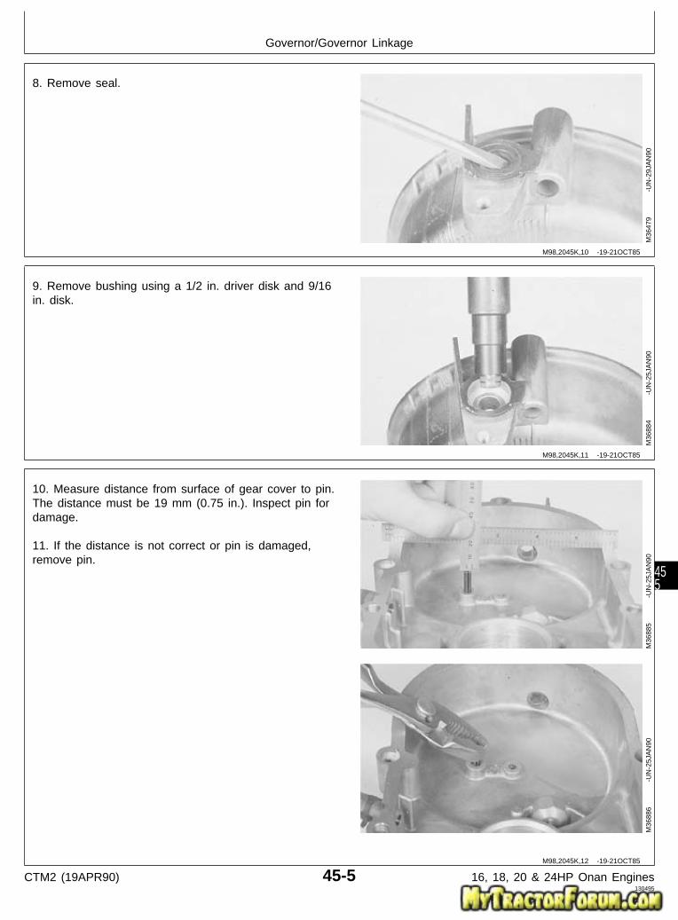
8. Remove seal.
M36
479
-UN
-29J
AN
90
9. Remove bushing using a 1/2 in. driver disk and 9/16in. disk.
M36
884
-UN
-25J
AN
90
10. Measure distance from surface of gear cover to pin.The distance must be 19 mm (0.75 in.). Inspect pin fordamage.
11. If the distance is not correct or pin is damaged,remove pin.
M36
885
-UN
-25J
AN
90M
3688
6
-U
N-2
5JA
N90
M98,2045K,10 -19-21OCT85
M98,2045K,11 -19-21OCT85
M98,2045K,12 -19-21OCT85
Governor/Governor Linkage
CTM2 (19APR90) 45-5 16, 18, 20 & 24HP Onan Engines130495
455

ASSEMBLE GOVERNOR LINKAGE
1. Install new pin in gear cover until pin is 19 mm (0.75in.) from surface of gear cover.
M36
887
-UN
-25J
AN
90M
3688
5
-U
N-2
5JA
N90
2. Install new bushing using a 1/2 in. driver disk and9/16 in. disk. Push bushing even with bottom of oil sealbore.
M36
884
-UN
-25J
AN
90
3. Install new seal, with lips of seal toward driver, usinga 1 in. driver disk. Push seal even with surface of gearcover.
M36
480
-UN
-29J
AN
90
M98,2045K,13 -19-21OCT85
M98,2045K,14 -19-21OCT85
M98,2045K,15 -19-21OCT85
Governor/Governor Linkage
CTM2 (19APR90) 45-6 16, 18, 20 & 24HP Onan Engines130495
456

4. Install governor arm shaft (A).
5. Apply thread lock and sealer (medium strength) onthreads of fork screws.
6. Install fork with bent ends upward. Install and tightentwo screws.
M36
478
-UN
-29J
AN
90
7. Support governor arm shaft. Hit end of fork screwsusing a punch so screws cannot be removed.
M36
888
-UN
-25J
AN
90
IMPORTANT: Ball bearing must be installed forproper governor shaft operation.
8. Install ball bearing in governor arm shaft hole.
9. Install governor arm shaft (A) in governor arm shafthole.
M36
889
-UN
-25J
AN
90
M98,2045K,16 -19-21OCT85
M98,2045K,17 -19-21OCT85
M98,2045K,18 -19-21OCT85
Governor/Governor Linkage
CTM2 (19APR90) 45-7 16, 18, 20 & 24HP Onan Engines130495
457

ASSEMBLE GOVERNOR ASSEMBLY
1. Install key in camshaft.
2. Install gear with timing mark “O” away from camshaft.
3. Align slot in gear with key in shaft.
4. Push camshaft into gear using a 1-3/8 in. driver diskand a press until camshaft is even with bottom of gearsurface.
M30
756
-UN
-14J
UL8
9
5. Apply clean engine oil on camshaft parts beforeassembly.
6. Install flyballs in flyball spacer (A) notches.
M36
310
-UN
-29J
AN
90
7. Install cup (A), hub (B), and fasten with snap ring.
M36
318
-UN
-29J
AN
90
M98,2045K,19 -19-21OCT85
M98,2025K,25 -19-09OCT85
M98,2025K,26 -19-09OCT85
Governor/Governor Assembly
CTM2 (19APR90) 45-8 16, 18, 20 & 24HP Onan Engines130495
458

INSTALL GOVERNOR ASSEMBLY ANDGOVERNOR LINKAGE
1. Install camshaft. (See Install Camshaft, Group 25 inthis manual.)
2. Install flywheel (E). (See Install Flywheel, Group 20 inthis manual.)
3. Install intake and exhaust valves (D). (See InstallIntake and Exhaust Valves, Group 15 in this manual.)
4. Install cylinder heads (C). (See Install Cylinder Heads,Group 10 in this manual.)
5. Install intake manifold (B). (See Install Intake Manifold,Group 10 in this manual.)
6. Install muffler and exhaust pipes (A). (See InstallIntake Manifold, Group 10 in this manual.)
7. Install engine. (See machine technical manual.)
A—Muffler and Exhaust PipesB—Intake ManifoldC—Cylinder HeadsD—Intake and Exhaust ValvesE—Flywheel
M36
474
-UN
-29J
AN
90
M98,2045K,20 -19-21OCT85
Governor/Governor Assembly and Linkage
CTM2 (19APR90) 45-9 16, 18, 20 & 24HP Onan Engines130495
459

Governor/Governor Assembly and Linkage
CTM2 (19APR90) 45-10 16, 18, 20 & 24HP Onan Engines130495
4510

SERVICE EQUIPMENT AND TOOLS
NOTE: Order tools from the U.S. SERVICE-GARD™ Catalog or from the European Microfiche Tool Catalog(MTC). Some tools may be available from a local supplier.
Name Use
1/2 in. Crowsfoot Wrench To remove carburetor
SERVICE PARTS KITS
The following kits are available through your partscatalog:
Choke Shaft KitGasket KitCarburetor Float KitFloat Valve And Seat KitIdle Needle KitIdle Speed Adjusting Screw KitThrottle Shaft KitCarburetor Repair Kit
SPECIFICATIONS
Item Measurement Specification
Carburetor Float Level Height from edge of bowl 0 to 1 mm (0.0 to 0.04 in.)
Carburetor Float Drop Depth below edge of bowl 5 mm (0.20 in.) Minimum
Breaker Point Gap Opening 0.41 mm (0.016 in.)
M98,2050K,1 -19-21OCT85
M98,2050K,2 -19-21OCT85
M98,2050K,3 -19-21OCT85
Group 50Carburetor
CTM2 (19APR90) 50-1 16, 18, 20 & 24HP Onan Engines130495
501

REMOVE CARBURETOR
NOTE: The carburetor removal includes procedures forall carburetors. The differences are noted. Thecarburetor can be removed with engine inmachine.
1. If equipped, turn reserve fuel lever to OFF position.
2. Remove air cleaner assembly. (See Remove AirCleaner in Group 05 of this manual.)
3. If engine is in machine, disconnect fuel line fromcarburetor.
4. If engine is in machine, loosen choke cable clampscrews (A). Disconnect cable from carburetor.
M36
985
-UN
-25J
AN
90
5. If engine is in machine, remove clip (A) to disconnectgovernor control linkage.
6. Loosen set screw. Remove breaker point cover, ifequipped.
T260 Engine
B43E, B43G, or E48G Engine
M36
986
-UN
-25J
AN
90M
3698
7
-U
N-2
5JA
N90
M98,2050K,4 -19-21OCT85
M98,2050K,5 -19-21OCT85
M98,2050K,6 -19-02FEB87
Carburetor/Carburetor
CTM2 (19APR90) 50-2 16, 18, 20 & 24HP Onan Engines130495
502

IMPORTANT: Be careful not to lose the point plungeror to allow dirt to enter the exposedplunger hole.
7. Loosen two set screws. Move point assembly, ifequipped, out of the way for access to carburetormounting bolts.
T260 Engine (Early point assembly)
B43E, B43G, OR B48G Engine (Early
M36
988
-UN
-25J
AN
90M
3698
9
-U
N-2
5JA
N90
8. Loosen two cap screws with JDG-333 CrowsfootWrench or short handled 1/2 in. open-end wrench.Remove carburetor.
T260 Engine
B43E, B43G, or B48G Engine
M36
990
-UN
-25J
AN
90M
3699
1
-U
N-2
5JA
N90
M98,2050K,7 -19-11FEB87
M98,2050K,8 -19-21OCT85
Carburetor/Carburetor
CTM2 (19APR90) 50-3 16, 18, 20 & 24HP Onan Engines130495
503

9. Remove gasket.
NOTE: If it is necessary to replace the mounting capscrews on the T260 engine, the intake manifoldmust be removed. (See Remove Intake Manifold,Group 10 in this manual.)
T260 Engine M36
992
-UN
-25J
AN
90
DISASSEMBLE CARBURETOR
NOTE: Carburetor disassembly includes procedures forall carburetors. The differences are noted.
1. Remove two cap screws. Remove choke controlbracket.
M36
954
-UN
-25J
AN
90
2. Remove two screws and choke valve.
M36
955
-UN
-25J
AN
90
3. Remove choke valve shaft.
4. Remove foam seal (A) from shaft.
Inspect choke shaft. Replace shaft if it shows excessivewear or is bent.
M36
956
-UN
-25J
AN
90
M98,2050K,9 -19-21OCT85
M98,2050K,10 -19-21OCT85
M98,2050K,11 -19-21OCT85
M98,2050K,12 -19-21OCT85
Carburetor/Carburetor
CTM2 (19APR90) 50-4 16, 18, 20 & 24HP Onan Engines130495
504

5. Remove two screws and throttle valve.
M36
957
-UN
-25J
AN
90
6. Remove throttle valve shaft.
7. Remove foam seal (A) from shaft.
Inspect throttle shaft. Replace shaft if it shows excessivewear or is bent.
M36
958
-UN
-25J
AN
90
8. Remove four screws to remove air intake.
M36
959
-UN
-25J
AN
90
M98,2050K,13 -19-21OCT85
M98,2050K,14 -19-21OCT85
M98,2050K,15 -19-21OCT85
Carburetor/Carburetor
CTM2 (19APR90) 50-5 16, 18, 20 & 24HP Onan Engines130495
505

9. Remove and discard gasket.
T260 Engine
B43E, B43G, B48G, P218G or P220G
M36
961
-UN
-25J
AN
90M
3696
8
-U
N-2
5JA
N90
10. Remove O-ring.
M36
960
-UN
-25J
AN
90
11. For T260 engine, remove float retaining screw.
M36
964
-UN
-25J
AN
90
M98,2050K,16 -19-02FEB87
M98,2050K,17 -19-21OCT85
M98,2050K,18 -19-21OCT85
Carburetor/Carburetor
CTM2 (19APR90) 50-6 16, 18, 20 & 24HP Onan Engines130495
506

12. Remove float, pivot pin, and needle valve.
Inspect needle valve. Replace valve if it is grooved orpitted.
Check float for dents or leaks. Replace if defective orloaded with fuel.
T260 Engine
B43E, B43G, B48G, P218G, or P220G
M36
965
-UN
-25J
AN
90M
3697
0
-U
N-2
5JA
N90
13. Remove seat. Remove washer (A).
Inspect needle seat area for wear or damage. Replaceseat if defective.
T260 Engine
B43E, B43G, B48G, P218G, or P220G
M36
966
-UN
-25J
AN
90M
3697
1
-U
N-2
5JA
N90
M98,2050K,19 -19-02FEB87
M98,2050K,20 -19-02FEB87
Carburetor/Carburetor
CTM2 (19APR90) 50-7 16, 18, 20 & 24HP Onan Engines130495
507

14. For B43E, B43G, B48G, P218G, or P220G engine,remove slow idle jet.
M36
972
-UN
-25J
AN
90
15. Remove reservoir plug and gasket.
T260 Engine
B43E, B43G, B48G, P218G, OR P220GM
3696
2
-U
N-2
5JA
N90
M36
969
-UN
-25J
AN
90
M98,2050K,21 -19-02FEB87
M98,2050K,22 -19-11FEB87
Carburetor/Carburetor
CTM2 (19APR90) 50-8 16, 18, 20 & 24HP Onan Engines130495
508

16. Remove main jet.
Inspect main jet. Replace if damaged.
T260 Engine
B43E, B43G, B48G, P218G, or P220G
M36
963
-UN
-25J
AN
90M
3697
3
-U
N-2
5JA
N90
17. For P218G or P220G engines, remove plastic capfrom idle mixture screw.
18. Remove idle mixture screw and spring.
Inspect seating surface of mixture screw. Replace if wornor damaged.
19. Remove idle speed screw (A) and spring.
Replace springs if weak or broken.M
3696
7
-U
N-2
5JA
N90
M98,2050K,23 -19-02FEB87
M98,2050K,24 -19-02FEB87
Carburetor/Carburetor
CTM2 (19APR90) 50-9 16, 18, 20 & 24HP Onan Engines130495
509

CLEAN CARBURETOR
IMPORTANT: Never clean holes or passages withsmall drill bits or wire because a slightenlargement or burring of these holeswill change the performance of thecarburetor. No other method ofcleaning other than solvent should beused.
1. Soak all metal components not replaced in carburetorcleaner. Do not soak non-metal floats or other non-metalparts.
2. Clean all carbon from carburetor bore. Be careful notto plug the idle or main fuel ports.
3. Dry out all passages with low pressure air 240 kPa(2.4 bar) (35 psi). Make sure all holes and passages areopen. Do not use rags or paper to dry parts.
ASSEMBLE CARBURETOR
NOTE: Carburetor assembly includes procedures for allcarburetors. The differences are noted.
Use new seals, gaskets, and O-ring when assemblingcarburetor.
1. Install idle speed screw (A) and spring.
2. Install idle mixture screw and spring. Turn idle mixturescrew in until lightly seated, then back it out 1-1/4 turns.
For P218G and P220G engines, install plastic cap onidle mixture screw.
M36
967
-UN
-25J
AN
90
M98,2050K,25 -19-21OCT85
M98,2050K,26 -19-11FEB87
Carburetor/Carburetor
CTM2 (19APR90) 50-10 16, 18, 20 & 24HP Onan Engines130495
5010

3. Install main jet.
T260 Engine
B43E, B43G, B48G, P218G, or P220G
M36
963
-UN
-25J
AN
90M
3697
3
-U
N-2
5JA
N90
4. Install reservoir plug and gasket.
T260 Engine
B43E, B43G, B48G, P218G, or P220G
M36
962
-UN
-25J
AN
90M
3696
9
-U
N-2
5JA
N90
M98,2050K,27 -19-02FEB87
M98,2050K,28 -19-02FEB87
Carburetor/Carburetor
CTM2 (19APR90) 50-11 16, 18, 20 & 24HP Onan Engines130495
5011

5. For B43E, G43G, B48G, P218G, or P220G engine,install slow idle jet.
M36
972
-UN
-25J
AN
90
6. Install seat and washer (A).
T260 Engine
B43E, B43G, B48G, P218G, or P220GM
3696
6
-U
N-2
5JA
N90
M36
971
-UN
-25J
AN
90
M98,2050K,29 -19-02FEB87
M98,2050K,30 -19-01JAN87
Carburetor/Carburetor
CTM2 (19APR90) 50-12 16, 18, 20 & 24HP Onan Engines130495
5012

7. Install float, pivot pin, and valve. Be sure wire onvalve is hooked over tab on float.
Install float, pivot pin, and valve. Be sure valve is hookedon float tab.
T260 Engine
B43E, B43G, B48G, P218G, or P220G
M36
965
-UN
-25J
AN
90M
3697
0
-U
N-2
5JA
N90
8. For T260 engine, fasten float assembly with retainingscrew. Make sure pivot pin is in the groove and that thefloat moves freely without binding.
M36
964
-UN
-25J
AN
90
M98,2050K,31 -19-02FEB87
M98,2050K,32 -19-21OCT85
Carburetor/Carburetor
CTM2 (19APR90) 50-13 16, 18, 20 & 24HP Onan Engines130495
5013

When checking float level and float drop, measure tofloat body, not seam.
9. Turn carburetor and check float setting usingstraightedge. Adjust floats so that they are even withedge of bowl or no more than 1 mm (0.04 in.) beyondedge. Bend float tab (A) to adjust.
Turn carburetor and hold pivot pin in place. Check floatsetting using a straightedge. Adjust floats so that theyare even with the edge of bowl or no more than 1 mm(0.04 in.) beyond edge. Bend float tang (A) to adjust.
T260 Engine
B43E, B43G, B48G, P218G, or P220G
M36
974
-UN
-25J
AN
90M
3697
5
-U
N-2
5JA
N90
10. Turn carburetor right side up and measure float drop.The distance from top of carburetor body to top of floatmust be at least 5 mm (0.20 in.). Bend float arm (A) toadjust. If float drop is adjusted, check float level again.
T260 Engine
B43,E, B43G, B48G, P218G, or P220G
M36
983
-UN
-25J
AN
90M
3698
4
-U
N-2
5JA
N90
M98,2050K,33 -19-11FEB87
M98,2050K,34 -19-02FEB87
Carburetor/Carburetor
CTM2 (19APR90) 50-14 16, 18, 20 & 24HP Onan Engines130495
5014

11. Install O-ring on carburetor intake.
M36
960
-UN
-25J
AN
90
12. Install gasket.
T260 Engine
B43E, B43G, B48G, P218G, OR P220GM
3696
1
-U
N-2
5JA
N90
M36
968
-UN
-25J
AN
90
13. Install air intake. Fasten with four screws.
M36
959
-UN
-25J
AN
90
M98,2050K,35 -19-21OCT85
M98,2050K,36 -19-02FEB87
M98,2050K,37 -19-21OCT85
Carburetor/Carburetor
CTM2 (19APR90) 50-15 16, 18, 20 & 24HP Onan Engines130495
5015

14. Apply a small amount of oil to the foam seal (A).Install foam seal and throttle valve shaft.
M36
958
-UN
-25J
AN
90
15. Install throttle valve. Adjust valve plate so that it iscentered in the bore before tightening the two screws.To center the plate, back off the throttle stop screw andcompletely close the throttle lever. Seat the valve plateby tapping with a small screwdriver, the tighten screws.
M36
957
-UN
-25J
AN
90
16. Apply a small amount of oil to the foam seal (A).Install foam seal and choke valve shaft.
M36
956
-UN
-25J
AN
90
17. Install choke valve. Adjust valve plate so that it iscentered in the bore before tightening two screws.
M36
955
-UN
-25J
AN
90
M98,2050K,38 -19-21OCT85
M98,2050K,39 -19-21OCT85
M98,2050K,40 -19-21OCT85
M98,2050K,41 -19-21OCT85
Carburetor/Carburetor
CTM2 (19APR90) 50-16 16, 18, 20 & 24HP Onan Engines130495
5016

18. Connect choke shaft wire and install choke controlbracket. Fasten with two cap screws.
M36
954
-UN
-25J
AN
90
INSTALL CARBURETOR
1. Put new gasket on intake manifold. Install carburetor.
T260 Engine M36
992
-UN
-25J
AN
90
2. Fasten carburetor with two cap screws. Tighten withJDG-333 Crowsfoot Wrench or short handled 1/2 in.open-end wrench.
T260 Engine
B43E, B43G, or B48G Engine
M36
990
-UN
-25J
AN
90M
3699
1
-U
N-2
5JA
N90
M98,2050K,42 -19-21OCT85
M98,2050K,43 -19-21OCT85
M98,2050K,44 -19-21OCT85
Carburetor/Carburetor
CTM2 (19APR90) 50-17 16, 18, 20 & 24HP Onan Engines130495
5017

3. Be sure point plunger (A) and gasket (B) are in place.Be sure plunger hole (C) is uncovered.
4. Apply thread sealant on threads of set screws andinstall breaker point assembly, if equipped.
T260 Engine M36
993
-UN
-25J
AN
90
5. Fasten point assembly, if equipped, with two setscrews.
6. Check point gap. Set gap to 0.41 mm (0.016 in.).
T260 Engine (Early point assembly)
B43E, B43G, or B48G Engine (EarlyM
3698
8
-U
N-2
5JA
N90
M36
989
-UN
-25J
AN
90
M98,2050K,45 -19-11FEB87
M98,2050K,46 -19-11FEB87
Carburetor/Carburetor
CTM2 (19APR90) 50-18 16, 18, 20 & 24HP Onan Engines130495
5018

IMPORTANT: Be sure to position breaker point leadso cover does not pinch it. Engine willnot run if cover and wire make a shortcircuit.
7. Install breaker point cover and tighten screw, ifequipped.
8. If engine is in unit, install clip (A) and connectgovernor control linkage.
T260 Engine
B43E, B43G, or B48G Engine
M36
986
-UN
-25J
AN
90M
3698
7
-U
N-2
5JA
N90
M98,2050K,47 -19-11FEB87
Carburetor/Carburetor
CTM2 (19APR90) 50-19 16, 18, 20 & 24HP Onan Engines130495
5019

9. If engine is in machine, connect and fasten fuel line tocarburetor with clamp (A).
NOTE: Adjust choke properly for satisfactory enginestarting and operation. The following adjustmentcan only be made with engine installed inmachine.
10. Install choke cable in bracket and fasten with screw(B).
11. Push choke control knob (on instrument panel) in allthe way.
12. Hold choke valve (C) straight up and tighten screw(D).
13. Pull choke control knob out. Choke valve must beclosed. Push knob in. Valve must be completely open.Adjust if needed.
14. Check that choke and throttle linkages operate freely.
15. Install air cleaner assembly. (See Install Air Cleanerin Group 05 of this manual.)
16. Adjust engine speed. (See machine technicalmanual.)
M36
994
-UN
-25J
AN
90
M98,2050K,48 -19-26NOV85
Carburetor/Carburetor
CTM2 (19APR90) 50-20 16, 18, 20 & 24HP Onan Engines130495
5020

SPECIFICATIONS
Item Measurement Specification
Lift Bracket Cap Screw Torque 11 ± 3 N·m (97 ± 27 lb-in.)
B43E, B43G, B48G, T260 Engine: Torque 51 ± 3 N·m (38 ± 2 lb-ft)Flywheel Cap Screw
P218G and P220G Engine: Flywheel Torque 67—75 N·m (50—55 lb-ft)Cap Screw
REMOVE STATOR
1. Remove engine. (See machine technical manual.)
2. Disconnect spark plug wire and voltage regulatorleads.
3. Remove cap screws to remove lift bracket (A) andmanifold cover (B).
4. Remove four cap screws on T260, P218G, or P220Gengine; five cap screws on B43E, B43G, B48G engine toremove side shroud (C).
M36
445
-UN
-29J
AN
90
5. Loosen hose clamp (A) to disconnect fuel impulse line(B).
M36
290
-UN
-29J
AN
90
M98,2055K,1 -19-11FEB87
M98,2055K,2 -19-02FEB87
M98,2060K,6 -19-05NOV85
Group 55Stator and Rectifier—Regulator
CTM2 (19APR90) 55-1 16, 18, 20 & 24HP Onan Engines130495
551

6. Disconnect governor spring (A).
7. Remove two screws to remove fuel pump (B).
8. Remove five cap screws to remove flywheel shroud(C).
M36
291
-UN
-29J
AN
90
IMPORTANT: Do not hold flywheel from turning witha pry bar. Doing so can damage thefins.
9. Fasten locking pliers to ring gear to prevent flywheelfrom turning.
N CAUTION: Loosen flywheel cap screw only twoturns. Do not remove cap screw. If cap screwis removed, flywheel may cause injury when itcomes loose.
10. Loosen cap screw two turns only.M
3629
2
-U
N-2
9JA
N90
M98,2060K,7 -19-05NOV85
M98,2055K,3 -19-22OCT85
Stator and Rectifier—Regulator/Stator
CTM2 (19APR90) 55-2 16, 18, 20 & 24HP Onan Engines130495
552

IMPORTANT: Do not pry on flywheel with ascrewdriver. Ceramic magnets and gearcase cover can be damaged.
11. Loosen flywheel using a puller.
12. Remove puller, cap screw, washer, and flywheel.
M36
293
-UN
-29J
AN
90
13. Disconnect stator lead from retaining clip (A).
14. Remove three cap screws. Gently pull stator offmounting posts.
M37
155
-UN
-25J
AN
90
INSTALL STATOR
1. Put stator on mounting posts and fasten with threecap screws. Tighten cap screws evenly so that stator isheld flat against posts.
Connect stator lead in retaining clip (A).
M37
155
-UN
-25J
AN
90
M98,2055K,4 -19-22OCT85
M98,2055K,5 -19-22OCT85
M98,2055K,6 -19-22OCT85
Stator and Rectifier—Regulator/Stator
CTM2 (19APR90) 55-3 16, 18, 20 & 24HP Onan Engines130495
553

IMPORTANT: Do not lubricate crankshaft taper. Thecrankshaft taper must be dry to holdthe flywheel tight.
2. Clean crankshaft taper before installing flywheel.
3. Apply pipe sealant on threads of flywheel cap screw.
4. Align keyway (A) in flywheel with key (B) in crankshaftand install flywheel.
5. Install washer and cap screw.
IMPORTANT: Do not hold flywheel from turning witha pry bar in the fins. Doing so maydamage the fins.
6. Fasten locking pliers to ring gear to prevent flywheelfrom turning.
7. On B43E, B43G, B48G, T260 engines, tighten capscrew to 51 ± 3 N·m (38 ± 2 lb-ft).
On P218G and P220G engine, tighten cap screw to67—75 N·m (50—55 lb-ft).
M36
297
-UN
-29J
AN
90M
3629
8
-U
N-2
9JA
N90
M98,2060K,73 -19-11FEB87
Stator and Rectifier—Regulator/Stator
CTM2 (19APR90) 55-4 16, 18, 20 & 24HP Onan Engines130495
554

8. Install flywheel shroud (C). Fasten with five capscrews.
9. Install fuel pump (B). Fasten with two screws.
10. Connect governor spring (A) in top hole of arm.
M36
291
-UN
-29J
AN
90
11. Connect fuel pump impulse line (B) and fasten withhose clamp (A).
M36
290
-UN
-29J
AN
90
M98,2055K,7 -19-26NOV85
M98,2055K,8 -19-22OCT85
Stator and Rectifier—Regulator/Stator
CTM2 (19APR90) 55-5 16, 18, 20 & 24HP Onan Engines130495
555

12. Install side shroud (C). Fasten with four cap screwson T260, P218G, and P220G engine; five cap screws onB43E, B43G, or B48G engine.
13. Install manifold cover (B) and lift bracket (A). Fastenwith three cap screws on T260 engine; two cap screwson B43E, or B48G engine. Tighten lift bracket cap screwto 11 ± 3 N·m (97 ± 27 lb-in.).
14. Connect spark plug wire and voltage regulator leads.Install the two stator leads on “AC” terminals and thebattery lead on “B+” terminal of voltage regulator.
15. Install engine. (See machine technical manual.)
T260 Engine Shown M36
445
-UN
-29J
AN
90
REPLACE RECTIFIER-REGULATOR
1. For T260 engine only, remove three cap screw (A) toremove manifold cover.
M37
239
-UN
-25J
AN
90
M98,2055K,9 -19-02FEB87
M98,2055K,10 -19-22OCT85
Stator and Rectifier—Regulator/Replace
CTM2 (19APR90) 55-6 16, 18, 20 & 24HP Onan Engines130495
556

2. Disconnect battery lead (A).
3. Disconnect two stator leads (B).
4. Remove cap screw (C).
5. Push regulator toward cap screw; then lift fromshroud.
6. Install new regulator and fasten with cap screw (C).
7. Connect two stator leads (B) to “AC” terminals.T260 Engine (Top Photo)
8. Connect battery lead (A) to “B+” terminal.
9. For T260 engine only, install manifold cover andfasten with three cap screws. Tighten lift bracket capscrew to 11 ± 3 N·m (97 ± 27 lb-in.).
B43E, B43G, B48G, P21G, or P220G
M37
240
-UN
-25J
AN
90M
3724
1
-U
N-2
5JA
N90
M98,2055K,11 -19-02FEB87
Stator and Rectifier—Regulator/Replace
CTM2 (19APR90) 55-7 16, 18, 20 & 24HP Onan Engines130495
557

Stator and Rectifier—Regulator/Replace
CTM2 (19APR90) 55-8 16, 18, 20 & 24HP Onan Engines130495
558

SERVICE EQUIPMENT AND TOOLS
NOTE: Order tools from the U.S. SERVICE-GARD™ Catalog or from the European Microfiche Tool Catalog(MTC). Some tools may be available from a local supplier.
Name Use
Volt-Ohm-Amp Meter Check continuity
Armature Growler Check starter armature
13-Ton Puller Set Remove flywheel
Blind Hole Puller Set Pull bushings
Dial Indicator Check armature shaft thrust gap
M98,2060K,1 -19-05NOV85
Group 60Starter
CTM2 (19APR90) 60-1 16, 18, 20 & 24HP Onan Engines130495
601

SPECIFICATIONS
Item Measurement Specification
BENDIX DRIVE STARTER
Starter Pinion Backlash 0.13—0.89 mm (0.005—0.035)
Brushes Wear Length 6.35 mm (0.25 in.) minimum
Armature Lock Nut Torque 30 ± 3 N·m (265 ± 27 lb-in.)
Battery Terminal Nut Torque 6 ± 1 N·m (53 ± 9 lb-in.)
Negative Brush Cap Screw Torque 4.5 ± 0.5 N·m (40 ± 4.5 lb-in.)
End Cap Thru-Bolts Torque 7 ± 1 N·m (62 ± 9 lb-in.)
SOLENOID DRIVE STARTER
Brushes Wear Length 11.5 mm (0.45 in.) minimum
End Cap Thru-Bolts Torque 5.7 ± 1.1 N·m (50 ± 10 lb-in.)
Solenoid Screws Torque 6 ± 1 N·m (53 ± 9 lb-in.)
Armature Shaft Thrust Gap Clearance 0.1 to 0.5 mm (0.004 to 0.020 in.)
Pinion-to-Stop Ring Gap Clearance 0.5 to 2.0 mm (0.020 to 0.079 in.)
Starter Mounting Cap Screws Torque 34 ± 1 N·m (300 ± 9 lb-in.)
B43E, B43G, B48G, T260 Engines: Torque 51 ± 3 N·m (38 ± 2 lb-ft)Flywheel Mounting Cap Screw
Lift Bracket Cap Screw Torque 11 ± 3 N·m (97 ± 27 lb-in.)
M98,2060K,2 -19-11FEB87
Starter/Specifications
CTM2 (19APR90) 60-2 16, 18, 20 & 24HP Onan Engines130495
602

SERVICE PARTS KITS
The following kits are available through your partscatalog:
Solenoid Kit
Bushing Kit
Brush Kit
Hardware Kit
Clutch Kit
Shift Lever Kit
REMOVE STARTER—B43E, B43G, B48G,AND T260 ENGINES
NOTE: See Starting Circuit Diagnosis in machinetechnical manual before removing starter.
1. Remove engine. (See machine technical manual.)
2. Disconnect spark plug wire and voltage regulatorleads.
3. Remove cap screw to remove lift bracket (A) andmanifold cover (B).
4. Remove four cap screws on T260 engine; five capscrews on B43E, B43G, or B48G engine, to remove sideshroud (C).
T260 Engine Shown M36
445
-UN
-29J
AN
90
M98,2060K,3 -19-26NOV85
M98,2060K,4 -19-11FEB87
Starter/Starter
CTM2 (19APR90) 60-3 16, 18, 20 & 24HP Onan Engines130495
603

5. Loosen hose clamp (A) to disconnect fuel impulse line(B).
M36
290
-UN
-29J
AN
90
6. Disconnect governor spring (A).
7. Remove two screws to remove fuel pump (B).
8. Remove five cap screws to remove flywheel shroud(C).
M36
291
-UN
-29J
AN
90
M98,2060K,6 -19-05NOV85
M98,2060K,7 -19-05NOV85
Starter/Starter
CTM2 (19APR90) 60-4 16, 18, 20 & 24HP Onan Engines130495
604

NOTE: Measure starter pinion gear backlash to check forwear.
9. Pull starter pinion gear outward until teeth contactflywheel ring gear. Measure starter pinion gear backlash.
STARTER PINION SPECIFICATIONS
Item New Part
Backlash 0.13—0.89 (0.005—0.035 in.)
If backlash exceeds 0.89 mm (0.035 in.), replace starterpinion.
M36
437
-UN
-29J
AN
90
IMPORTANT: Do not hold flywheel from turning witha pry bar. Doing so can damage thefins.
10. Fasten locking pliers to ring gear to prevent flywheelfrom turning.
N CAUTION: Loosen flywheel cap screw only twoturns. Do not remove cap screw. If cap screwis removed, flywheel may cause injury when itcomes loose.
11. Loosen cap screw two turns only.
M36
292
-UN
-29J
AN
90
IMPORTANT: Do not pry on flywheel with ascrewdriver. Ceramic magnets and gearcase cover can be damaged.
12. Loosen flywheel using a puller.
13. Remove puller, cap screw, washer, and flywheel.
M36
293
-UN
-29J
AN
90
M98,2060K,8 -19-05NOV85
M98,2060K,9 -19-05NOV85
M98,2060K,10 -19-05NOV85
Starter/Starter
CTM2 (19APR90) 60-5 16, 18, 20 & 24HP Onan Engines130495
605

14. Remove two cap screws. Remove starter.
Bendix Drive Starter Shown M37
102
-UN
-25J
AN
90
REMOVE STARTER—P218G AND P220GENGINES
NOTE: See Starting Circuit Diagnosis in machinetechnical manual before removing starter.
1. Remove engine. (See machine technical manual.)
2. Disconnect spark plug wire.
3. Remove cap screw to remove lift bracket and manifoldcover.
4. Remove cap screws to remove side shroud.
5. Remove cap screws from flywheel shroud. Moveflywheel shroud just far enough to remove starter.
6. Remove two cap screws (A) to remove starter.
M46
014
-UN
-08J
AN
90
DISASSEMBLE BENDIX DRIVE STARTER
1. Remove rubber dust cover.
M37
104
-UN
-25J
AN
90
M98,2060K,11 -19-05NOV85
M98,2060K,11E -19-11FEB87
M98,2060K,12 -19-05NOV85
Starter/Starter
CTM2 (19APR90) 60-6 16, 18, 20 & 24HP Onan Engines130495
606

2. Remove two thru-bolts.
M37
105
-UN
-25J
AN
90
NOTE: Brush springs may snap out of the end cap whenit is removed. Be careful not to lose springs.
3. Remove end cap.
M37
106
-UN
-25J
AN
90
4. Remove two cap screws to remove negative brushes.
M37
107
-UN
-25J
AN
90
5. Remove nut to remove positive side brushes.
Check all brushes for cracks or excessive wear. Replacebrushes if they are worn shorter than 6.35 mm (0.25 in.).
Inspect springs. Replace springs if they are weak orbroken.
Always replace springs and brushes as a set if any aredefective.
M37
108
-UN
-25J
AN
90
M98,2060K,13 -19-05NOV85
M98,2060K,14 -19-05NOV85
M98,2060K,15 -19-05NOV85
M98,2060K,16 -19-05NOV85
Starter/Starter
CTM2 (19APR90) 60-7 16, 18, 20 & 24HP Onan Engines130495
607

6. Pull armature assembly out of housing.
Clean housing and magnets. Magnets must be securelyglued to inside of housing and must be free of cracks.
Replace housing if magnets are loose or cracked.
M37
109
-UN
-25J
AN
90
7. Hold armature in soft-jaw vise.
8. Remove lock nut and disassemble parts (I—A).
Clean and check starter drive components for wear ordamage. Inspect bushing in cap (C) for wear.
Replace damaged or worn parts.
A—ArmatureB—Thrust WasherC—CapD—SealE—Drive PinionF—SpacerG—SpringH—WasherI—Lock Nut
M37
110
-UN
-25J
AN
90M
3711
1
-U
N-2
5JA
N90
M98,2060K,17 -19-05NOV85
M98,2060K,18 -19-05NOV85
Starter/Starter
CTM2 (19APR90) 60-8 16, 18, 20 & 24HP Onan Engines130495
608

IMPORTANT: Do not clean armature with solvent.Solvent can damage insulation onwindings. Use only mineral spirits anda brush.
9. Inspect commutator. Look for roughness, burned bars,or any material which might cause short circuits betweenbars. If necessary, clean and touch up with 400 gritsandpaper. NEVER use emery cloth. Clean all dust fromarmature when finished.
10. Test for grounded windings using an ohmmeter ortest light.
Touch probes on commutator and armature core.Armature windings are connected in series, so only onecommutator bar needs to be checked.
If test shows continuity, a winding is grounded and thearmature must be replaced.
M37
112
-UN
-25J
AN
90
11. Test for open circuited windings using an ohmmeteror test light.
Touch probes on two different commutator bars. If testshows no continuity, there is an open circuit and thearmature must be replaced.
M37
113
-UN
-25J
AN
90
M98,2060K,19 -19-05NOV85
M98,2060K,20 -19-05NOV85
Starter/Starter
CTM2 (19APR90) 60-9 16, 18, 20 & 24HP Onan Engines130495
609

12. Test for short circuited windings using a growler. Putarmature in growler and hold a hacksaw blade aboveeach slot while slowly rotating armature.
If coil is shorted, the blade will vibrate on the slot.
NOTE: A short circuit most often occurs because ofcopper dust or filings between two commutatorsegments.
13. If test indicates short circuited windings, clean thecommutator of dust and filings. Check the armatureagain. If the test still indicates a short circuit, replace thearmature.
M17
166
-UN
-24A
PR
89
ASSEMBLE BENDIX DRIVE STARTER
1. Apply a generous film of silicone base grease, suchas GE Versilube 322-L or equivalent, to the worm gear.
2. Apply a thin film of grease to bearing surfaces (A).
M37
114
-UN
-25J
AN
90
M98,2060K,21 -19-05NOV85
M98,2060K,22 -19-05NOV85
Starter/Starter
CTM2 (19APR90) 60-10 16, 18, 20 & 24HP Onan Engines130495
6010

3. Assemble parts (A-I) in sequence order.
4. Hold armature in a soft-jaw vise. Tighten lock nut to30 ± 3 N·m (265 ± 27 lb-in.).
A—ArmatureB—Thrust WasherC—CapD—SealE—Drive PinionF—SpacerG—SpringH—WasherI—Lock Nut
M37
111
-UN
-25J
AN
90M
3711
5
-U
N-2
5JA
N90
5. Put armature assembly in housing. Align notch in capwith mark on housing.
M37
109
-UN
-25J
AN
90
M98,2060K,23 -19-05NOV85
M98,2060K,24 -19-05NOV85
Starter/Starter
CTM2 (19APR90) 60-11 16, 18, 20 & 24HP Onan Engines130495
6011

6. Install positive side brushes. Fasten with fiber washer,flat washer, lock washer, and nut.
Tighten nut to 6 ± 1 N·m (53 ± 9 lb-in.).
7. Install negative brushes. Fasten with cap screws andtighten to 4.5 ± 0.5 N·m (40 ± 4.5 lb-in.).
8. Install springs.
M37
108
-UN
-25J
AN
90M
3710
7
-U
N-2
5JA
N90
9. To make temporary brush holders, cut steel bandinginto four pieces, 76mm (3 in.) long. Bend flanges 25 mm(1 in.) long as shown.
10. Push brushes down on the springs and hold them inplace with the four brush holders. Make sure thatchamfered side of brush is up and that the wires do notrub against the commutator or end cap.
M37
116
-UN
-25J
AN
90
11. Apply a light film of grease to bushing (A).
12. Align tab and notch (B); then install end cap onstarter.
M37
117
-UN
-25J
AN
90
M98,2060K,25 -19-05NOV85
M98,2060K,26 -19-05NOV85
M98,2060K,27 -19-05NOV85
Starter/Starter
CTM2 (19APR90) 60-12 16, 18, 20 & 24HP Onan Engines130495
6012

13. Hold end cap in place and remove four temporarybrush holding clips.
14. Be sure notches on both end caps are aligned withtabs on housing; then fasten with two thru-bolts. Tightenbolts to 7 ± 1 N·m (62 ± 9 lb-in.).
M37
118
-UN
-25J
AN
90
15. Install rubber dust cover.
M37
104
-UN
-25J
AN
90
M98,2060K,28 -19-05NOV85
M98,2060K,29 -19-05NOV85
Starter/Starter
CTM2 (19APR90) 60-13 16, 18, 20 & 24HP Onan Engines130495
6013

BENCH TEST SOLENOID DRIVE STARTER
NOTE: Perform bench test before disassembling thestarter motor to determine the cause of theproblem.
IMPORTANT: Never operate motor longer than 20seconds. Allow at least two minutes forcooling and battery recovery beforeoperating again. Overheating, causedby excessive operation, will seriouslydamage starting motor.
1. Connect a 12-volt battery (A) to starter batteryterminal (B) and starter frame (C). Use heavy dutycables.
2. Connect a remote start switch (D) between switchterminal (E) and battery terminal (B).
NOTE: A short piece of wire with a small clip on the endwill allow a more positive connection at theswitch terminal.
A—12-Volt BatteryB—Battery TerminalC—Starter FrameD—Remote Start SwitchE—Switch Terminal
M37
149
-UN
-29A
UG
88
When switch is activated, starter should engage and run.
IF SOLENOID CHATTERS; hold-in winding isopen-circuited.
IF NOTHING HAPPENS; either the solenoid pull-inwinding is open-circuited or mechanical parts aresticking.
IF SOLENOID ENGAGES, BUT MOTOR DOES NOTRUN; check solenoid switch continuity, brushes,armature, and field windings.
Solenoid cannot be repaired, replace it.
M98,2060K,30 -19-05NOV85
M98,2060K,31 -19-26NOV85
Starter/Starter
CTM2 (19APR90) 60-14 16, 18, 20 & 24HP Onan Engines130495
6014

DISASSEMBLE SOLENOID DRIVE STARTER
1. Remove nut (A) to disconnect field coil lead.
2. Remove two screws (B).
M37
150
-UN
-25J
AN
90
3. Remove solenoid switch (A), spring (B), and plunger(C).
Clean and inspect parts. Replace solenoid assembly ifspring is weak or broken or if other parts are defective.
M37
129
-UN
-25J
AN
90
NOTE: If bench test indicated solenoid problems, usean ohmmeter or test light to check switch.
4. Touch one probe of tester to field coil terminal andother probe to battery terminal. There should be nocontinuity.
M37
151
-UN
-25J
AN
90
5. With tester probes still on field coil terminal andbattery terminal, push spring loaded switch button (A).There should be continuity when button is pushed in allthe way.
M37
152
-UN
-25J
AN
90
M98,2060K,32 -19-05NOV85
M98,2060K,33 -19-05NOV85
M98,2060K,34 -19-05NOV85
M98,2060K,35 -19-05NOV85
Starter/Starter
CTM2 (19APR90) 60-15 16, 18, 20 & 24HP Onan Engines130495
6015

6. Test for open circuits by touching probes to switchterminal (A) and to field coil terminal (B). There shouldbe continuity.
M37
153
-UN
-25J
AN
90
7. Touch probes to switch terminal (A) and to solenoidbody (C). There should be continuity.
If the solenoid fails any of the tests, it is defective andmust be replaced.
M37
154
-UN
-25J
AN
90
8. Remove two screws (A) and two thru-bolts (B).
M37
121
-UN
-25J
AN
90
NOTE: Make a mark across front bracket, field coil, andend cap to align parts in assembly.
9. Remove end cap. Remove thrust washers (A) whichmay stick on end cap or around armature shaft.
Inspect bushing in end cap for excessive wear. Replaceend cap assembly if cap is bent or deformed, or ifbushing is worn.
M37
122
-UN
-25J
AN
90
M98,2060K,36 -19-05NOV85
M98,2060K,37 -19-05NOV85
M98,2060K,38 -19-05NOV85
M98,2060K,39 -19-05NOV85
Starter/Starter
CTM2 (19APR90) 60-16 16, 18, 20 & 24HP Onan Engines130495
6016

10. Pull springs back to remove two field coil brushesfrom brush holder. Remove brush holder.
M37
123
-UN
-25J
AN
90
11. Use an ohmmeter or test light to check for continuity.Touch one probe of tester to brush mounting plate andother probe to each of the field coil brush holders (A). Ifthere is continuity, replace the brush holder assembly.
M37
139
-UN
-29J
AN
90
12. Pull spring back to remove negative brush.
Measure brush length. Replace brush if worn belowminimum length of 11.5 mm (0.45 in.).
M37
124
-UN
-25J
AN
90M
3712
5
-U
N-2
5JA
N90
M98,2060K,40 -19-05NOV85
M98,2060K,41 -19-05NOV85
M98,2060K,42 -19-05NOV85
Starter/Starter
CTM2 (19APR90) 60-17 16, 18, 20 & 24HP Onan Engines130495
6017

13. To replace negative brush, cut off worn brush andinstall new one using a soldering gun and 60-40 rosincore solder. Newly installed wire should be approximatelysame length as the original.
M37
140
-UN
-29A
UG
88
14. Remove field coil.
IMPORTANT: Do not clean starter parts with solvent.Solvent can damage insulation onwindings. Use only mineral spirits anda brush or wipe clean with a cloth.
Clean and inspect field coil. Check for bare wires orbroken insulation that may cause grounding.
M37
126
-UN
-25J
AN
90
15. Test for grounded field winding using an ohmmeteror test light. Touch one probe of tester to field coil brushand other probe to field frame. Be sure the brush lead isnot touching the frame. If there is continuity, the coil isgrounded and the field frame assembly must bereplaced.
M36
757
-UN
-29A
UG
88
16. Test for open field coil by touching a probe to eachfield coil brush. If there is no continuity, the field coil isopen and the field frame assembly must be replaced.
M36
758
-UN
-29A
UG
88
M98,2060K,43 -19-05NOV85
M98,2060K,44 -19-05NOV85
M98,2060K,45 -19-05NOV85
M98,2060K,46 -19-05NOV85
Starter/Starter
CTM2 (19APR90) 60-18 16, 18, 20 & 24HP Onan Engines130495
6018

17. Check brushes for cracks or excessive wear.
Replace brushes if they are worn shorter than 11.5 mm(0.45 in.).
M37
127
-UN
-25J
AN
90
18. To replace brushes, melt solder from brush leadconnection and install new brush. If additional solder isneeded, use only 60-40 rosin core solder.
M37
141
-UN
-25J
AN
90
19. Remove rubber seal (A) and steel plug (B).
M37
130
-UN
-25J
AN
90
M98,2060K,47 -19-05NOV85
M98,2060K,48 -19-05NOV85
M98,2060K,49 -19-05NOV85
Starter/Starter
CTM2 (19APR90) 60-19 16, 18, 20 & 24HP Onan Engines130495
6019

20. Remove armature (A) and lever (B).
Inspect armature for signs of dragging against poleshoes.
Inspect lever for cracks or excessive wear. Replace ifdefective.
Inspect commutator. Look for roughness, burned bars, orany material which might cause short circuits betweenbars. If necessary, clean and touch up with 400sandpaper. Never use emery cloth. Clean all dust fromarmature when finished.
M37
131
-UN
-25J
AN
90
21. Test for grounded windings using an ohmmeter ortest light.
Touch probes on armature core and commutator bar.Armature windings are connected in series, so only onecommutator bar needs to be checked.
If test shows continuity, a winding is grounded and thearmature is defective.
M37
132
-UN
-25J
AN
90
22. Test for open circuited windings using an ohmmeteror test light.
Touch probes on two different commutator bars. If testshows no continuity, there is an open circuit and thearmature is defective.
M37
133
-UN
-25J
AN
90
M98,2060K,50 -19-05NOV85
M98,2060K,51 -19-05NOV85
M98,2060K,52 -19-05NOV85
Starter/Starter
CTM2 (19APR90) 60-20 16, 18, 20 & 24HP Onan Engines130495
6020

23. Test for short circuited windings using a growler. Putarmature in growler and hold a hacksaw blade aboveeach slot while slowly rotating armature.
If coil is shorted, the blade will vibrate on the slot.
NOTE: A short circuit most often occurs because ofcopper dust or filing between two commutatorsegments.
24. If test indicates short circuited windings, clean thecommutator of dust and filings. Check the armatureagain. If the test still indicates a short circuit, thearmature is defective.
The armature is not serviceable. If any of the testsindicate grounded, shorted, or open circuited windings,replace the entire starter.
M17
166
-UN
-24A
PR
89
IMPORTANT: Do not clean overrunning clutch insolvent. The clutch contains greasewhich would be removed.
NOTE: Check overrunning clutch before removing it fromarmature.
25. Turn clutch drive counterclockwise by hand. Pinionshould turn freely.
26. Turn pinion clockwise. A definite resistance shouldbe felt.
If clutch is free-wheeling in both directions, or if it showsresistance when turned counterclockwise, it is defective.
Replace overrunning clutch if it is defective or if piniongear shows excessive wear or damage.
M37
134
-UN
-25J
AN
90
M98,2060K,53 -19-05NOV85
M98,2060K,54 -19-05NOV85
Starter/Starter
CTM2 (19APR90) 60-21 16, 18, 20 & 24HP Onan Engines130495
6021

27. Hold armature assembly in a soft-jawed vise. Slidestop ring (A) down using a piece of pipe.
28. Push snap ring (B) from groove.
M37
135
-UN
-25J
AN
90M
3713
6
-U
N-2
5JA
N90
29. Remove snap ring (A), stop ring (B), overrunningclutch (C), and baffle plate (D).
A—Snap RingB—Stop RingC—Overrunning ClutchD—Baffle Plate
M37
137
-UN
-25J
AN
90
M98,2060K,55 -19-05NOV85
M98,2060K,56 -19-05NOV85
Starter/Starter
CTM2 (19APR90) 60-22 16, 18, 20 & 24HP Onan Engines130495
6022

30. Check bushing in front frame for excessive wear.
If it is necessary to remove bushing (A), use a 3/8 in.blind-hole puller and slide hammer.
NOTE: Thrust washer will be pulled along with bushing.
M37
138
-UN
-25J
AN
90
ASSEMBLE SOLENOID DRIVE STARTER
1. If front frame bushing is being replaced, press newbushing (A) and thrust washer (B) into front frame. Usea 5/8 in. driver to install washer tight against shoulder ofcounterbore.
M37
142
-UN
-25J
AN
90
M98,2060K,57 -19-05NOV85
M98,2060K,58 -19-05NOV85
Starter/Starter
CTM2 (19APR90) 60-23 16, 18, 20 & 24HP Onan Engines130495
6023

2. Install baffle plate (A), overrunning clutch (B), stopring (C), and snap ring (D). Be sure flange of baffle plate(A) is pointing upward.
3. Put snap ring (D) in groove. Pull stop ring (C) overthe snap ring.
A—Baffle PlateB—Overrunning ClutchD—Stop RingE—Snap Ring
M37
143
-UN
-25J
AN
90
4. Apply Multemp PS No. 2 grease or equivalent to bothends of armature shaft and to the lever (B). Apply lightoil to the overrunning clutch splines.
5. Install armature assembly (A) and lever (B) into frontframe. Note the position of the lever.
M37
131
-UN
-25J
AN
90
6. Install steel plug (B) and rubber seal (A).
M37
130
-UN
-25J
AN
90
M98,2060K,59 -19-05NOV85
M98,2060K,60 -19-05NOV85
M98,2060K,61 -19-05NOV85
Starter/Starter
CTM2 (19APR90) 60-24 16, 18, 20 & 24HP Onan Engines130495
6024

7. Install field coil. Be sure notch in field coil flangealigns with rubber seal.
M37
126
-UN
-25J
AN
90
8. Install negative brush and hold it in place with thespring.
M37
124
-UN
-25J
AN
90
9. Put brush holder assembly on commutator and installfield coil brushes. Pull springs back and push all threebrushes against commutator, then release springs to holdbrushes.
M37
123
-UN
-25J
AN
90
NOTE: Install same number of thrust washers as wasremoved when disassembling starter.
10. Apply grease to thrust washers (A) to hold them toend cap.
11. Install end cap. Be sure slot in end cap aligns withrubber seal.
M37
122
-UN
-25J
AN
90
M98,2060K,62 -19-05NOV85
M98,2060K,63 -19-05NOV85
M98,2060K,64 -19-05NOV85
M98,2060K,65 -19-05NOV85
Starter/Starter
CTM2 (19APR90) 60-25 16, 18, 20 & 24HP Onan Engines130495
6025

12. Install two screws (A).
13. Install two thru-bolts (B) and tighten to 5.7 ± 1.1 N·m(50 ± 10 lb-in.).
M37
121
-UN
-25J
AN
90
14. Apply grease to the lever fork and apply light oil tothe plunger (C).
15. Connect plunger (C) to lever fork and install spring(B) and solenoid switch (A). Note position of switchterminal on solenoid.
M37
129
-UN
-25J
AN
90
16. Fasten solenoid with two screws. Tighten screws to6 ± 1 N·m (53 ± 9 lb-in.).
17. Connect field coil lead and fasten with nut (A).
M37
144
-UN
-25J
AN
90
M98,2060K,66 -19-05NOV85
M98,2060K,67 -19-05NOV85
M98,2060K,68 -19-05NOV85
Starter/Starter
CTM2 (19APR90) 60-26 16, 18, 20 & 24HP Onan Engines130495
6026

18. Check armature shaft thrust gap. Set dial indicatoron pinion then raise the armature shaft to determinethrust gap.
SPECIFICATION
Item Nominal Value
Armature Shaft Thrust Gap 0.1 to 0.5 mm(0.004 to 0.020 in.)
If the thrust gap is not within the nominal value limits,add or remove thrust washers shown in Step 10. M
3714
5
-U
N-2
5JA
N90
M37
146
-UN
-25J
AN
90
NOTE: Normally the pinion clearance will not be affectedby servicing the starter unless the solenoid isreplaced.
19. To check pinion clearance, connect a 12-volt battery(A) to starter frame (B). Connect a remote switch (C)between solenoid terminal (D) and battery (A). Useheavy duty cables.
A—12-Volt BatteryB—Starter FrameC—Remote Start SwitchD—Solenoid Switch Terminal
M37
147
-UN
-26A
PR
89
M98,2060K,69 -19-05NOV85
M98,2060K,70 -19-05NOV85
Starter/Starter
CTM2 (19APR90) 60-27 16, 18, 20 & 24HP Onan Engines130495
6027

IMPORTANT: To avoid solenoid overheating, do notleave solenoid activated longer thannecessary to measure clearance.
20. Close the switch to activate solenoid which will shiftthe pinion into cranking position. Measure clearancebetween the pinion and stop ring.
SPECIFICATION
Item Nominal Value
Pinion-to-Stop Ring 0.5 to 2.0 mmClearance (0.020 to 0.079 in.)
If clearance is not within the nominal value limits, add orremove shims between solenoid and front frame. SeeStep 15.
Adding shims provided with Solenoid Repair Kit,decreases the amount of clearance.
21. After assembly, perform bench test. (See “BenchTest Solenoid Drive Starter” in this group.)
M37
148
-UN
-25J
AN
90
INSTALL STARTER—P218G AND P220GENGINES
1. Install starter. Tighten cap screws (A) to 26 N·m (230lb-in.).
2. Align flywheel shroud and install cap screws.
3. Install side shroud and cap screws.
4. Install manifold and lift bracket. Tighten cap screw to11 ± 3 N·m (97 ± 27 lb-in.).
5. Connect spark plug wire.
6. Install engine. (See machine technical manual.)
M46
014
-UN
-08J
AN
90
M98,2060K,71 -19-05NOV85
M98,2060K,72A -19-02FEB87
Starter/Starter
CTM2 (19APR90) 60-28 16, 18, 20 & 24HP Onan Engines130495
6028

INSTALL STARTER—B43E, B43G, B48G,AND T260 ENGINES
1. Install starter. Tighten two cap screws to 34 ± 1 N·m(300 ± 9 lb-in.).
Bendix Drive Starter Shown M36
439
-UN
-29J
AN
90
IMPORTANT: Do not lubricate crankshaft taper. Thecrankshaft taper must be dry to holdthe flywheel tight.
2. Clean crankshaft taper before installing flywheel.
3. Apply pipe sealant on threads of flywheel cap screw.
4. Align keyway (A) in flywheel with key (B) in crankshaftand install flywheel.
5. Install washer and cap screw.
IMPORTANT: Do not hold flywheel from turning witha pry bar in the fins. Doing so maydamage the fins.
6. Fasten locking pliers to ring gear to prevent flywheelfrom turning.
7. On B43E, B43G, B48G, T260 engines, tighten capscrew to 51 ± 3 N·m (38 ± 2 lb-ft).
On P218G and P220G engine, tighten cap screw to67—75 N·m (50—55 lb-ft).
M36
297
-UN
-29J
AN
90M
3629
8
-U
N-2
9JA
N90
M98,2060K,72 -19-11FEB87
M98,2060K,73 -19-11FEB87
Starter/Starter
CTM2 (19APR90) 60-29 16, 18, 20 & 24HP Onan Engines130495
6029

NOTE: For engines with adjustable starter bracket,measure starter pinion gear backlash using thefollowing procedure. For all other units withnon-adjustable starter bracket, go to Step 21.
8. Pull starter pinion gear outward until teeth contactflywheel ring gear. Measure starter pinion gear backlash.Backlash specification is 0.51 ± 0.38 mm (0.020 ± 0.15in.).
If backlash is correct, go to Step 21.
9. If backlash is not correct, loosen starter cap screws(A) and move starter bracket (B) to obtain correctbacklash.
Tighten starter cap screws to hold bracket in position.Check backlash again.
M36
437
-UN
-29J
AN
90M
3643
8
-U
N-2
9JA
N90
IMPORTANT: Do not hold flywheel from turning witha pry bar. Doing so can damage thefins.
10. Fasten locking pliers to ring gear to prevent flywheelfrom turning.
N CAUTION: Loosen flywheel cap screw only twoturns. Do not remove cap screw. If cap screwis removed, flywheel may cause injury when itcomes loose.
11. Loosen cap screw two turns only.M
3629
2
-U
N-2
9JA
N90
M98,2060K,78 -19-26NOV85
M98,2060K,9 -19-05NOV85
Starter/Starter
CTM2 (19APR90) 60-30 16, 18, 20 & 24HP Onan Engines130495
6030

IMPORTANT: Do not pry on flywheel with ascrewdriver. Ceramic magnets and gearcase cover can be damaged.
12. Loosen flywheel using a puller.
13. Remove puller, cap screw, washer, and flywheel.
M36
293
-UN
-29J
AN
90
14. Tighten starter cap screws to 34 ± 1 N·m (300 ± 9lb-in.).
M36
439
-UN
-29J
AN
90
IMPORTANT: Do not lubricate crankshaft taper. Thecrankshaft taper must be dry to holdthe flywheel tight.
15. Clean crankshaft taper before installing flywheel.
16. Apply pipe sealant on threads of flywheel cap screw.
17. Align keyway (A) in flywheel with key (B) incrankshaft and install flywheel.
18. Install washer and cap screw.
IMPORTANT: Do not hold flywheel from turning witha prybar in the fins. Doing so maydamage the fins.
19. Fasten locking pliers to ring gear to prevent flywheelfrom turning.
20. Tighten cap screw to 51 ± 3 N·m (38 ± 2 lb-ft).
M36
297
-UN
-29J
AN
90M
3629
8
-U
N-2
9JA
N90
M98,2060K,10 -19-05NOV85
M98,2060K,79 -19-26NOV85
M98,2060K,80 -19-26NOV85
Starter/Starter
CTM2 (19APR90) 60-31 16, 18, 20 & 24HP Onan Engines130495
6031

21. Install flywheel shroud (C). Fasten with five capscrews.
22. Install fuel pump (B). Fasten with two screws.
23. Connect governor spring (A) in top hole of arm.
M36
291
-UN
-29J
AN
90
24. Connect fuel pump impulse line (B) and fasten withhose clamp (A).
M36
290
-UN
-29J
AN
90
M98,2060K,75 -19-26NOV85
M98,2060K,76 -19-26NOV85
Starter/Starter
CTM2 (19APR90) 60-32 16, 18, 20 & 24HP Onan Engines130495
6032

25. Install side shroud (C). Fasten with four cap screwson T260 engine; five cap screws on B43E, B43G, orB48G engine.
26. Install manifold cover (B) and lift bracket (A). Fastenwith three cap screws on T260 engine; two cap screwson B43E, B43G, or B48G engine. Tighten lift bracket capscrew to 11 ± 3 N·m (97 ± 27 lb-in.).
27. Connect spark plug wire and voltage regulator leads.Install the two stator leads on “AC” terminals and thebattery lead on “B+” terminal of voltage regulator.
28. Install engine. (See machine technical manual.)
T260 Engine Shown M36
445
-UN
-29J
AN
90
M98,2060K,77 -19-26NOV85
Starter/Starter
CTM2 (19APR90) 60-33 16, 18, 20 & 24HP Onan Engines130495
6033

Starter/Starter
CTM2 (19APR90) 60-34 16, 18, 20 & 24HP Onan Engines130495
6034

REPLACE BREAKER POINTS ANDCONDENSER—B43E, B43G, B48G, ANDT260 ENGINES
NOTE: On later engines, the condenser is located onside of air filter bracket.
1. Remove air cleaner assembly. (See Remove AirCleaner in Group 05 in this manual.)
2. Remove breaker point cover.
M37
242
-UN
-25J
AN
90
3. Remove two set screws to remove breaker points.
4. Loosen screw (A) to disconnect coil and condenserleads.
5. Remove screw (B) to remove condenser.
6. Install new condenser and point assembly. Applythread sealant on threads of set screws and fastenbreaker points.
Early Point Assembly Shown
M37
243
-UN
-25J
AN
90
7. Check breaker point gap. Turn engine flywheel untilpoints are at their widest gap. Adjust gap to 0.41 mm(0.016 in.) using a flat feeler gauge.
M37
244
-UN
-25J
AN
90
M98,2065K,1 -19-02FEB87
M98,2065K,2 -19-05NOV85
M98,2065K,3 -19-05NOV85
Group 65Ignition System
CTM2 (19APR90) 65-1 16, 18, 20 & 24HP Onan Engines130495
651

8. Be sure coil lead wire is in notch in the base; theninstall breaker point cover. Tighten cover set screw snugonly so cover is not crushed or deformed.
9. Install air cleaner assembly. (See Install Air Cleaner inGroup 05 in this manual.)
M37
242
-UN
-25J
AN
90
REPLACE IGNITION COIL—B43E, B43G,B48G, AND T260 ENGINES
1. Remove air cleaner assembly. (See Remove AirCleaner in Group 05 in this manual.)
2. Disconnect spark plug wires (A).
3. Loosen screw (B) to remove coil.
4. Remove wires (C) and (D).
5. To install coil, fasten breaker point lead to negative (-) T260 Engine (Top Photo)
terminal (D) and ignition switch lead to positive (+)terminal (C).
6. Install coil and fasten with screw clamp (B).
7. Connect spark plug wires (A).
8. Install air cleaner assembly. (See Install Air Cleaner inGroup 05 in this manual.)
B43E, B43G, B48G Engine (BottomM
3715
6
-U
N-2
5JA
N90
M37
157
-UN
-25J
AN
90
M98,2065K,4 -19-05NOV85
M98,2065K,5 -19-11FEB87
Ignition System/Ignition Coil
CTM2 (19APR90) 65-2 16, 18, 20 & 24HP Onan Engines130495
652

REPLACE IGNITION COIL—P218G ANDP220G ENGINES
1. Remove air cleaner assembly. (See Remove AirCleaner in Group 05 in this manual.)
2. Disconnect wire leads (A—F).
3. Remove two cap screws to remove ignition coil.
4. Install ignition coil and two cap screws.
5. Connect wire leads and install air cleaner assembly.(See Install Air Cleaner in Group 05 in this manual.)
A—Spark Plug WireB—Spark Plug WireC—Condenser WireD—Wiring Harness (Key Switch)E—Orange Wire (Ignition Coil)F—Black Wire (Ignition Coil)
M46
015
-UN
-08J
AN
90
REPLACE IGNITION MODULE ANDMAGNETIC RING—P218G AND P220GENGINES
1. Remove air cleaner assembly. (See Group 05 in thismanual.)
2. Remove flywheel. (See Group 20 in this manual.)
3. Remove three cap screws. Gently pull stator (A) offmounting posts.
M46
016
-UN
-08J
AN
90
M98,2065K,6 -19-11FEB87
M98,2065K,7 -19-11FEB87
Ignition System/Ignition Coil
CTM2 (19APR90) 65-3 16, 18, 20 & 24HP Onan Engines130495
653

4. Remove key (A) and magnetic ring (B).
5. Remove two cap screws to remove ignition coil (C).
6. Install coil (C), magnetic ring (B)—marked“FLYWHEEL SIDE”, and key (A).
7. Install starter and cap screws.
8. Install flywheel. (See Group 20 in this manual.)
9. Install air cleaner. (See Group 05 in this manual.) M46
017
-UN
-08J
AN
90
M98,2065K,8 -19-02FEB87
Ignition System/Ignition Coil
CTM2 (19APR90) 65-4 16, 18, 20 & 24HP Onan Engines130495
654

Page
Group 00— . . . . . . . . . . . . . . . . . . . . . . . . . . Introduction . . . . . . . . . . . . . . . . . . . . . . . . 00-1About This Manual . . . . . . . . . . . . . . . . . . . 00-2Engine Serial Number Plate . . . . . . . . . . . . . 00-3Engine Specifications . . . . . . . . . . . . . . . . . 00-3Engine Application Chart . . . . . . . . . . . . . . . 00-4Hardware Torque Specifications . . . . . . . . . . 00-4
Group 05—Air Cleaner and BreatherSpecifications . . . . . . . . . . . . . . . . . . . . . . 05-1Air Cleaner
Remove . . . . . . . . . . . . . . . . . . . . . . . . 05-1Install . . . . . . . . . . . . . . . . . . . . . . . . . . 05-3
Breather, RepairT260 Engine . . . . . . . . . . . . . . . . . . . . . 05-4B43E, B43G, or B48G, Engines . . . . . . . . . 05-5
Group 10—Intake Manifold and Cylinder HeadsService Equipment and Tools . . . . . . . . . . . . 10-1Service Parts Kits . . . . . . . . . . . . . . . . . . . 10-1Specifications . . . . . . . . . . . . . . . . . . . . . . 10-2Intake Manifold
Remove . . . . . . . . . . . . . . . . . . . . . . . . 10-2Install . . . . . . . . . . . . . . . . . . . . . . . . . . 10-4
Cylinder HeadRemove . . . . . . . . . . . . . . . . . . . . . . . . 10-8Install . . . . . . . . . . . . . . . . . . . . . . . . . 10-11
Group 15—Intake and Exhaust ValvesEssential Tools . . . . . . . . . . . . . . . . . . . . . 15-1Service Equipment and Tools . . . . . . . . . . . . 15-1Service Parts Kits . . . . . . . . . . . . . . . . . . . 15-2Specifications . . . . . . . . . . . . . . . . . . . . . . 15-3Intake and Exhaust Valves
Remove . . . . . . . . . . . . . . . . . . . . . . . . 15-5Install . . . . . . . . . . . . . . . . . . . . . . . . . 15-12Measure and Adjust Valve Clearance . . . . 15-15
Group 20—FlywheelService Equipment and Tools . . . . . . . . . . . . 20-1Other Material . . . . . . . . . . . . . . . . . . . . . . 20-1
Page
Specifications . . . . . . . . . . . . . . . . . . . . . . 20-1Flywheel
Remove . . . . . . . . . . . . . . . . . . . . . . . . 20-2Install . . . . . . . . . . . . . . . . . . . . . . . . . . 20-4
Group 25—CamshaftEssential Tools . . . . . . . . . . . . . . . . . . . . . 25-1Service Equipment and Tools . . . . . . . . . . . . 25-1Other Material . . . . . . . . . . . . . . . . . . . . . . 25-1Service Parts Kits . . . . . . . . . . . . . . . . . . . 25-2Specifications . . . . . . . . . . . . . . . . . . . . . . 25-3Camshaft
Remove . . . . . . . . . . . . . . . . . . . . . . . . 25-4Disassemble and Inspect . . . . . . . . . . . . . 25-7Assemble . . . . . . . . . . . . . . . . . . . . . . 25-11Install . . . . . . . . . . . . . . . . . . . . . . . . . 25-13
Group 30—Connecting Rods and PistonsService Equipment and Tools . . . . . . . . . . . . 30-1Other Material . . . . . . . . . . . . . . . . . . . . . . 30-1Service Parts Kits . . . . . . . . . . . . . . . . . . . 30-1Specifications . . . . . . . . . . . . . . . . . . . . . . 30-2Connecting Rod
Measure End Play . . . . . . . . . . . . . . . . . . 30-4Measure Bearing Clearance . . . . . . . . . . . 30-7
Pistons and Connecting RodsRemove . . . . . . . . . . . . . . . . . . . . . . . . 30-9Inspect . . . . . . . . . . . . . . . . . . . . . . . . 30-13Deglaze Cylinder Bores . . . . . . . . . . . . . 30-21Assemble . . . . . . . . . . . . . . . . . . . . . . 30-21Install . . . . . . . . . . . . . . . . . . . . . . . . . 30-23
Group 35—Crankshaft and Main BearingsEssential Tools . . . . . . . . . . . . . . . . . . . . . 35-1Service Equipment and Tools . . . . . . . . . . . . 35-1Other Material . . . . . . . . . . . . . . . . . . . . . . 35-1Service Parts Kits . . . . . . . . . . . . . . . . . . . 35-2Specifications . . . . . . . . . . . . . . . . . . . . . . 35-2
Continued on next page
COPYRIGHT© 1989DEERE & COMPANY
Moline, IllinoisAll rights reserved
A John Deere ILLUSTRUCTION™ Manual
All information, illustrations and specifications in this manual are based onthe latest information available at the time of publication. The right isreserved to make changes at any time without notice.
CTM2-19-19APR90
Contents
CTM2 (19APR90) i 16, 18, 20 & 24HP Onan Engines130495
00
05
10
15
20
25
30
35
40
45
50
55
60
65

Page
Crankshaft and Main BearingsRemove . . . . . . . . . . . . . . . . . . . . . . . . 35-3Inspect . . . . . . . . . . . . . . . . . . . . . . . . . 35-6Install . . . . . . . . . . . . . . . . . . . . . . . . . . 35-9
Group 40—Lubrication SystemEssential Tools . . . . . . . . . . . . . . . . . . . . . 40-1Service Equipment and Tools . . . . . . . . . . . . 40-1Other Material . . . . . . . . . . . . . . . . . . . . . . 40-1Service Parts Kits . . . . . . . . . . . . . . . . . . . 40-2Specifications . . . . . . . . . . . . . . . . . . . . . . 40-3Oil Pump
Remove . . . . . . . . . . . . . . . . . . . . . . . . 40-4Disassemble and Inspect . . . . . . . . . . . . . 40-6Assemble . . . . . . . . . . . . . . . . . . . . . . . 40-7Install . . . . . . . . . . . . . . . . . . . . . . . . . . 40-7
Oil Pressure Regulating ValveRemove . . . . . . . . . . . . . . . . . . . . . . . 40-10Install . . . . . . . . . . . . . . . . . . . . . . . . . 40-12
Oil BaseRemove and Inspect . . . . . . . . . . . . . . . 40-14Install . . . . . . . . . . . . . . . . . . . . . . . . . 40-16
Oil Filter AdapterRemove . . . . . . . . . . . . . . . . . . . . . . . 40-21Install . . . . . . . . . . . . . . . . . . . . . . . . . 40-22
Oil Line AdapterRemove . . . . . . . . . . . . . . . . . . . . . . . 40-24Install . . . . . . . . . . . . . . . . . . . . . . . . . 40-25
Group 45—GovernorService Equipment and Tools . . . . . . . . . . . . 45-1Other Material . . . . . . . . . . . . . . . . . . . . . . 45-1Service Parts Kits . . . . . . . . . . . . . . . . . . . 45-1Specifications . . . . . . . . . . . . . . . . . . . . . . 45-1Governor Assembly and Linkage
Remove . . . . . . . . . . . . . . . . . . . . . . . . 45-2Governor Assembly
Disassemble and Inspect . . . . . . . . . . . . . 45-2Governor Linkage
Disassemble and Inspect . . . . . . . . . . . . . 45-4Assemble . . . . . . . . . . . . . . . . . . . . . . . 45-6
Governor AssemblyAssemble . . . . . . . . . . . . . . . . . . . . . . . 45-8
Governor Assembly and LinkageInstall . . . . . . . . . . . . . . . . . . . . . . . . . . 45-9
Group 50—CarburetorService Equipment and Tools . . . . . . . . . . . . 50-1Service Parts Kits . . . . . . . . . . . . . . . . . . . 50-1Specifications . . . . . . . . . . . . . . . . . . . . . . 50-1
Page
CarburetorRemove . . . . . . . . . . . . . . . . . . . . . . . . 50-2Disassemble . . . . . . . . . . . . . . . . . . . . . 50-4Clean . . . . . . . . . . . . . . . . . . . . . . . . . 50-10Assemble . . . . . . . . . . . . . . . . . . . . . . 50-10Install . . . . . . . . . . . . . . . . . . . . . . . . . 50-17
Group 55—Stator and Rectifier—RegulatorSpecifications . . . . . . . . . . . . . . . . . . . . . . 55-1Stator
Remove . . . . . . . . . . . . . . . . . . . . . . . . 55-1Install . . . . . . . . . . . . . . . . . . . . . . . . . . 55-3
Rectifier-RegulatorReplace . . . . . . . . . . . . . . . . . . . . . . . . . . 55-6
Group 60—StarterService Equipment and Tools . . . . . . . . . . . . 60-1Specifications . . . . . . . . . . . . . . . . . . . . . . 60-2Service Parts Kits . . . . . . . . . . . . . . . . . . . 60-3Starter
Remove . . . . . . . . . . . . . . . . . . . . . . . . 60-3Repair Bendix Drive Starter . . . . . . . . . . . 60-6Repair Solenoid Drive Starter . . . . . . . . . 60-15Install . . . . . . . . . . . . . . . . . . . . . . . . . 60-28
Group 65—Ignition SystemBreaker Points and Condenser
Replace . . . . . . . . . . . . . . . . . . . . . . . . . 65-1Ignition Coil
Replace . . . . . . . . . . . . . . . . . . . . . . . . . 65-2
Contents
CTM2 (19APR90) ii 16, 18, 20 & 24HP Onan Engines130495
00
05
10
15
20
25
30
35
40
45
50
55
60
65
Recommended