17-April-09 TILC09 Global Design Effort 1
Barry BarishTILC09 – Tsukuba, Japan
17-April-09
ILC / GDE Report
Electron Cloud at CesrTA
17-April-09 TILC09 Global Design Effort 2
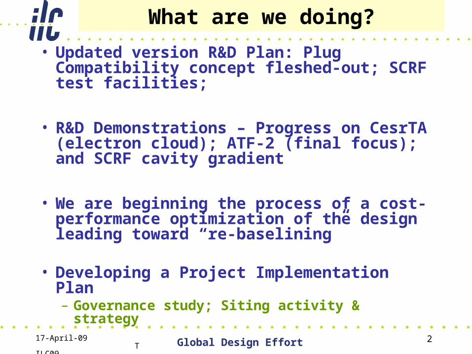
What are we doing?
• Updated version R&D Plan: Plug Compatibility concept fleshed-out; SCRF test facilities;
• R&D Demonstrations – Progress on CesrTA (electron cloud); ATF-2 (final focus); and SCRF cavity gradient
• We are beginning the process of a cost-performance optimization of the design leading toward “re-baselining”
• Developing a Project Implementation Plan
– Governance study; Siting activity & strategy
17-April-09 TILC09 Global Design Effort 3Global Design Effort
R&D Plan - Technical Design Phase
• “Living Document”• A 60 page document with details
of all R&D programs, schedules and resources.
• New: Release 3
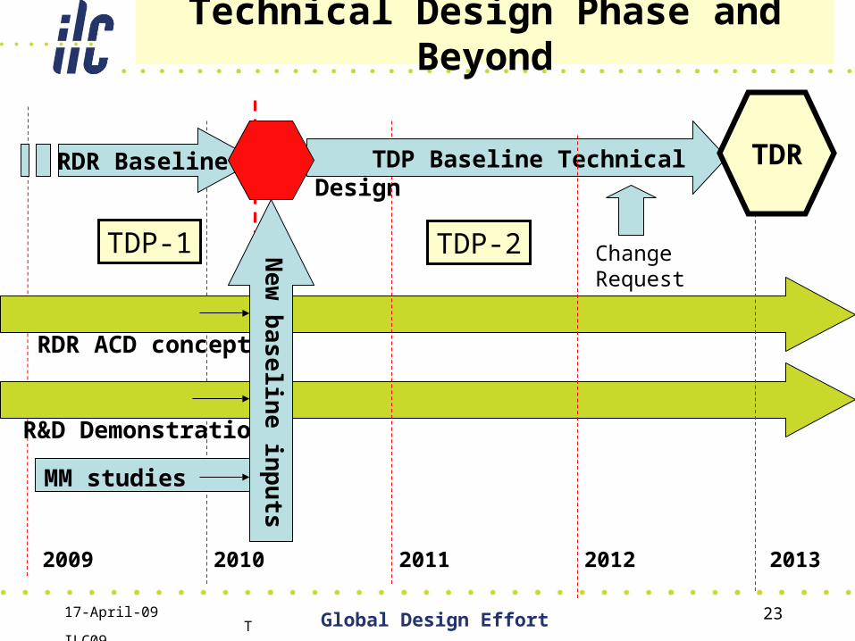
• Technical Design Phase– Phase 1 2010 (critical R&D
demonstrations; new baseline
– Phase 2 2012 (technical design and implementation plan –> construction proposal ready
Global Design Effort
17-April-09 TILC09 Global Design Effort 4
R&D Plan
• The document has two parts:
– A summary of the primary goals and schedules for the Technical Design Phases (TDP-1 and TDP-2)
– Appendices which contain detailed information on world-wide resources and the complete project work-package structure
17-April-09 TILC09 Global Design Effort 5Global Design Effort 5
Major Milestones for TDP 1
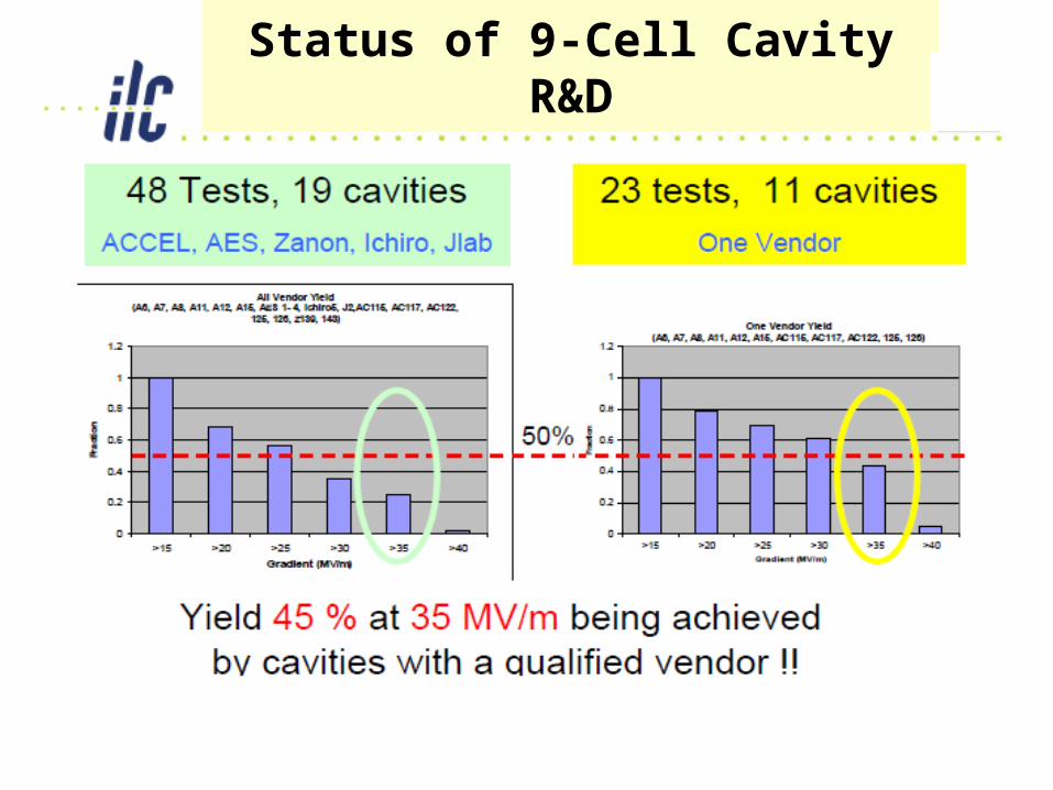
SCRF• High Gradient R&D - globally coordinated program to
demonstrate gradient by 2010 with 50%yield;
ATF-2 at KEK
• Demonstrate Fast Kicker performance and Final Focus Design
Electron Cloud Mitigation – (CesrTA)• Electron Cloud tests at Cornell to establish mitigation
and verify one damping ring is sufficient.
Minimum Machine Studies (Cost/Performance) • Studies of possible cost reduction designs and
strategies for consideration in a re-baseline in 2010
17-April-09 TILC09 Global Design Effort 6
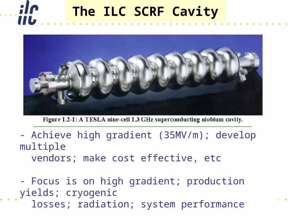
The ILC SCRF Cavity
- Achieve high gradient (35MV/m); develop multiple vendors; make cost effective, etc
- Focus is on high gradient; production yields; cryogenic losses; radiation; system performance
17-April-09 TILC09 Global Design Effort 7
Status of 9-Cell Cavity R&D
17-April-09 TILC09 Global Design Effort 8Oct 30, 2008
9th ICFA SeminarGlobal Design Effort 8
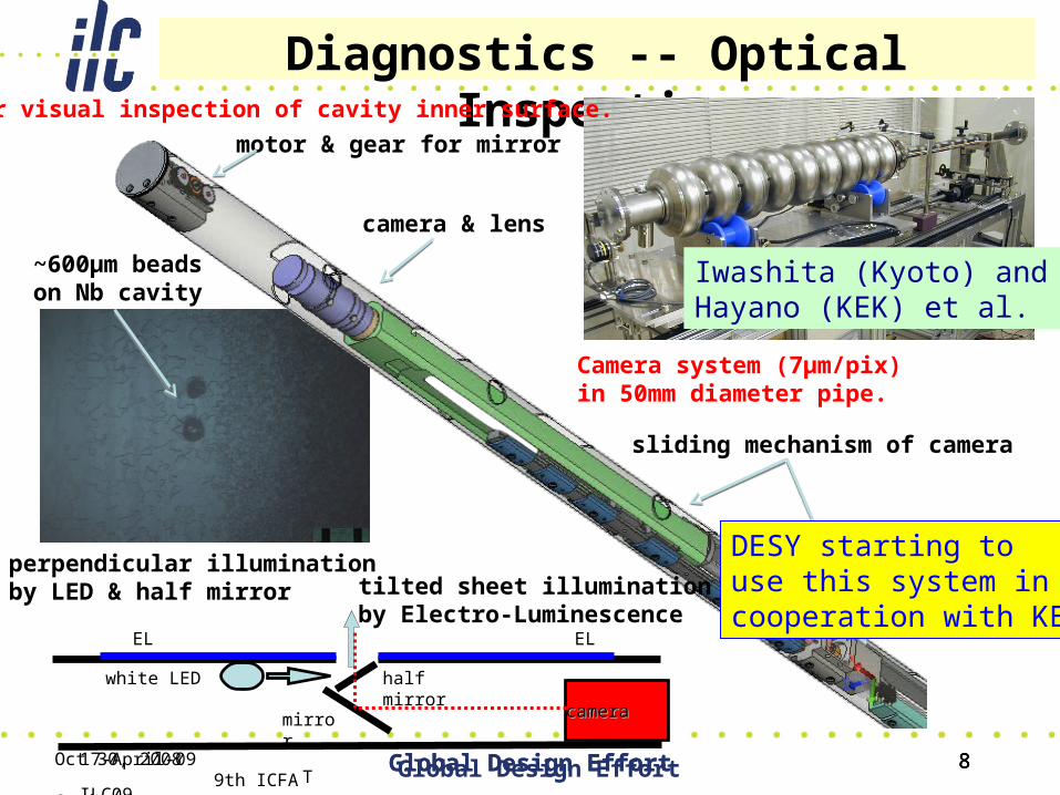
Diagnostics -- Optical Inspection
cameracamera
white LED half mirror
EL EL
mirror
motor & gear for mirror
camera & lens
sliding mechanism of camera
tilted sheet illuminationby Electro-Luminescence
perpendicular illumination by LED & half mirror
Camera system (7µm/pix) in 50mm diameter pipe.
For visual inspection of cavity inner surface.
~600µm beadson Nb cavity
8
Iwashita (Kyoto) and Hayano (KEK) et al.
Global Design Effort
DESY starting to use this system in cooperation with KEK
17-April-09 TILC09 Global Design Effort 9
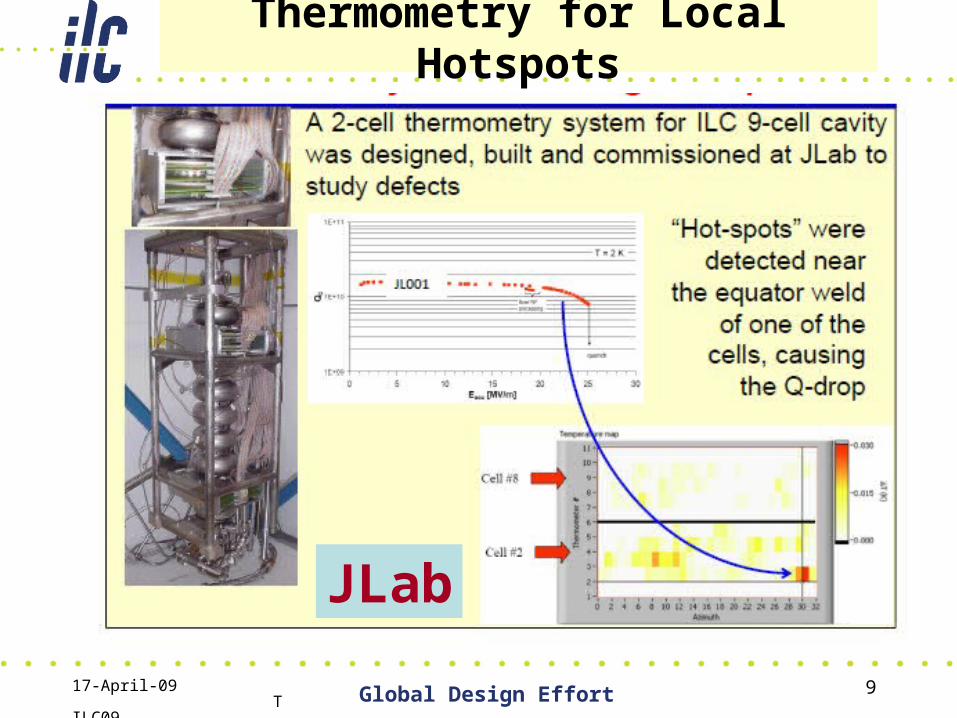
Thermometry for Local Hotspots
JLab
17-April-09 TILC09 Global Design Effort 10
17-April-09 TILC09 Global Design Effort 11
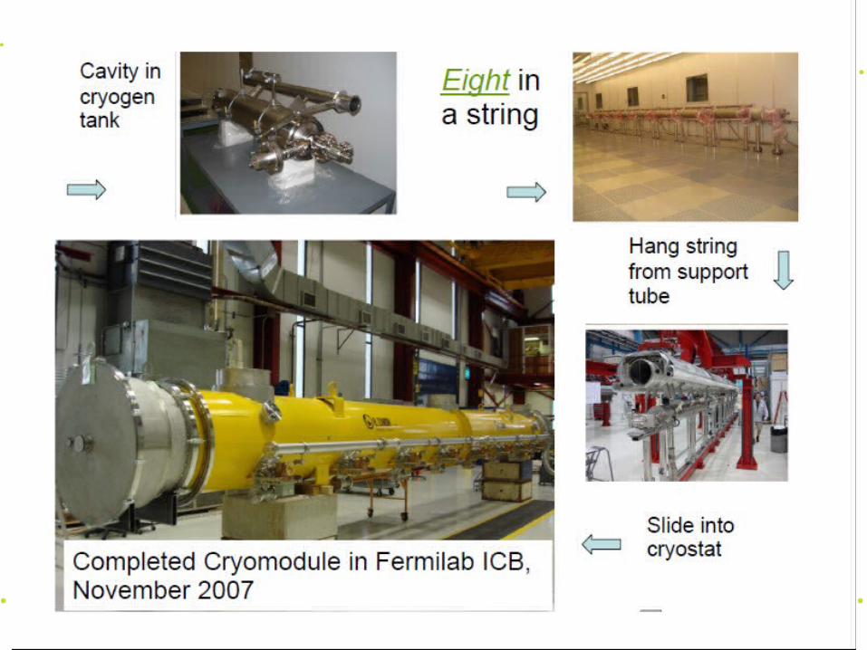
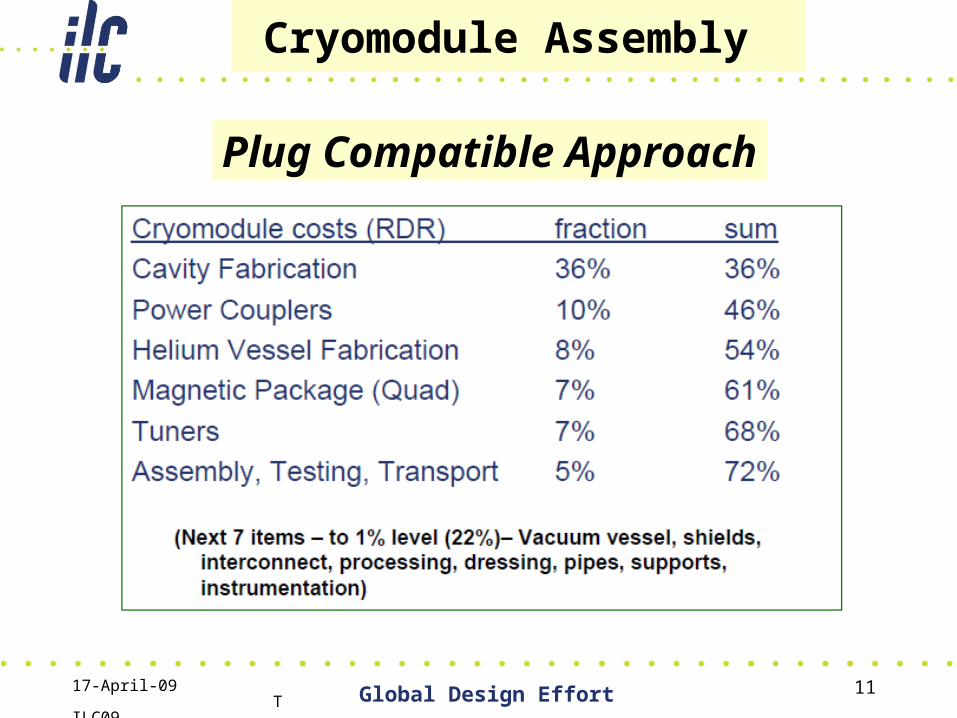
Cryomodule Assembly
Plug Compatible Approach
17-April-09 TILC09 Global Design Effort 12
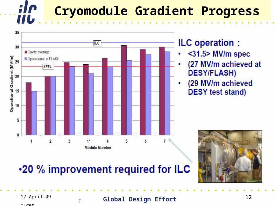
Cryomodule Gradient Progress
17-April-09 TILC09 Global Design Effort 13
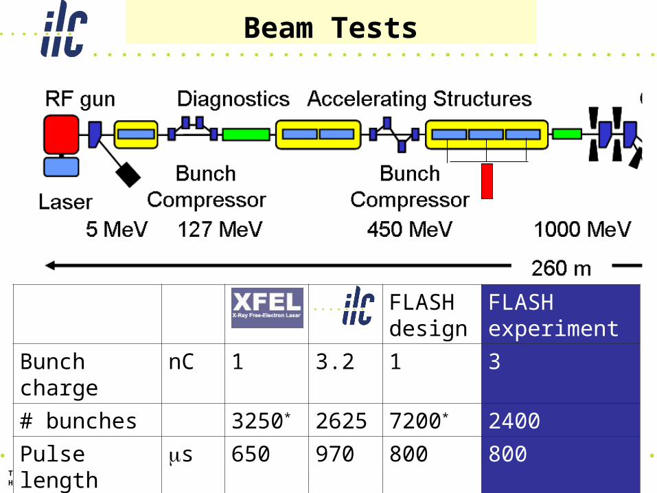
Beam Tests13
TTF/FLASH 9mA Mini-Workshop, January 16th, 2009Hans Weise / DESY
XFEL ILC FLASHdesign
FLASH experiment
Bunch charge nC 1 3.2 1 3
# bunches 3250* 2625 7200* 2400
Pulse length s 650 970 800 800
Current mA 5 9 9 9
17-April-09 TILC09 Global Design Effort 14Global Design Effort 14
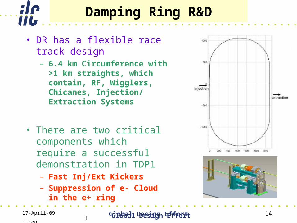
Damping Ring R&D
• DR has a flexible race track design– 6.4 km Circumference with >1
km straights, which contain, RF, Wigglers, Chicanes, Injection/ Extraction Systems
• There are two critical components which require a successful demonstration in TDP1– Fast Inj/Ext Kickers– Suppression of e- Cloud in
the e+ ring
17-April-09 TILC09 Global Design Effort 15
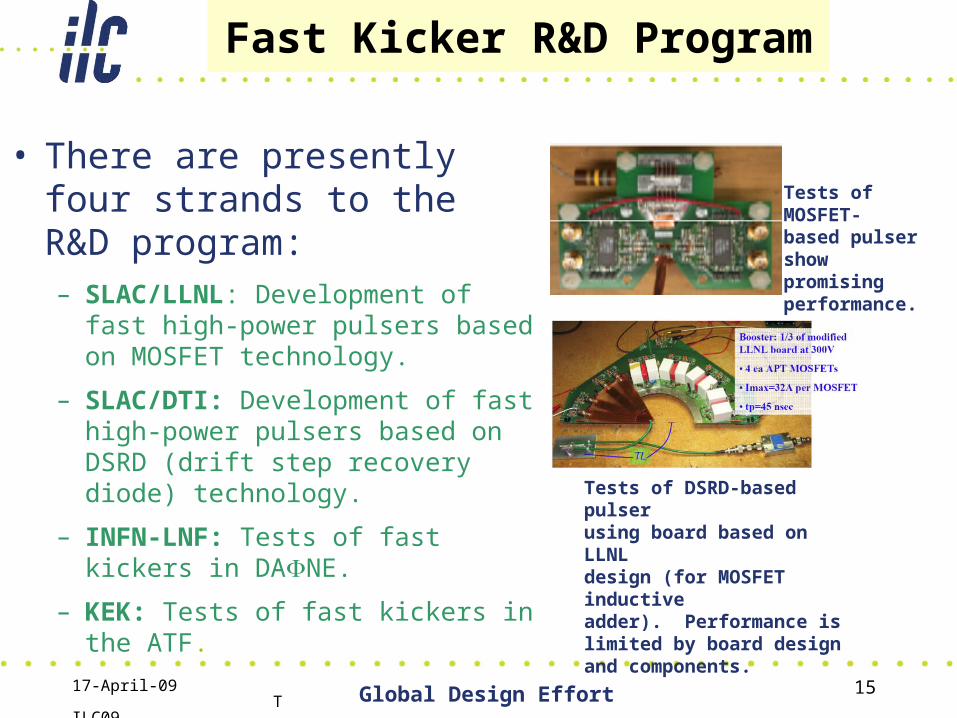
Fast Kicker R&D Program
• There are presently four strands to the R&D program:– SLAC/LLNL: Development of fast
high-power pulsers based on MOSFET technology.
– SLAC/DTI: Development of fast high-power pulsers based on DSRD (drift step recovery diode) technology.
– INFN-LNF: Tests of fast kickers in DANE.
– KEK: Tests of fast kickers in the ATF.
Tests of MOSFET-based pulser showpromising performance.
Tests of DSRD-based pulserusing board based on LLNLdesign (for MOSFET inductiveadder). Performance is limited by board design and components.
17-April-09 TILC09 Global Design Effort 16
Electron cloud – Goal
• In electron or proton storage rings, low energy electrons are accelerated by the high energy beam into the wall of the vacuum chamber where more electrons are emitted leading to the formation of an electron cloud.
• For ILC damping ring, need to ensure the e- cloud won’t blow up the e+ beam emittance.– Studied through simulations– Test vacuum pipe coatings, grooved chambers, and
clearing electrodes effect on e- cloud buildup– Do above in ILC style wigglers with low emittance beam
to minimize the extrapolation to the ILC.– Test program is underway at CESR Cornell (CesrTA)
17-April-09 TILC09 Global Design Effort 17
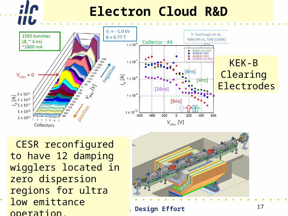
Electron Cloud R&D
KEK-B Clearing
Electrodes
CESR reconfigured to have 12 damping wigglers located in zero dispersion regions for ultra low emittance operation.
17-April-09 TILC09 Global Design Effort 18
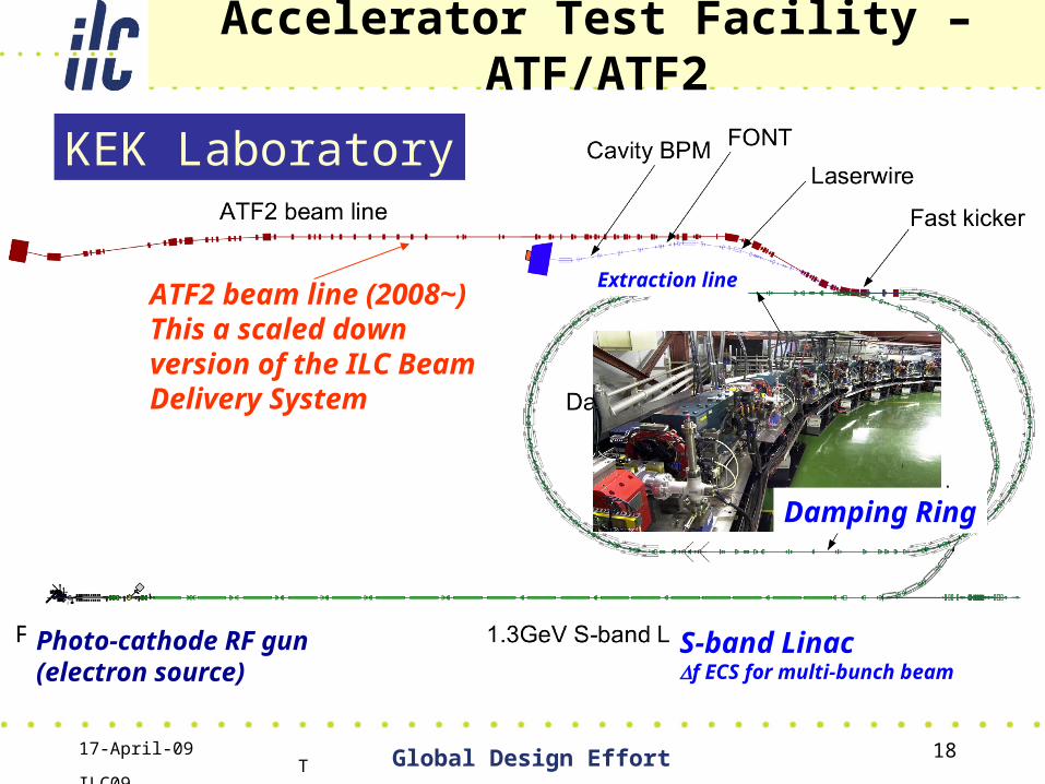
Photo-cathode RF gun(electron source)
S-band Linacf ECS for multi-bunch beam
Extraction lineATF2 beam line (2008~) This a scaled down version of the ILC Beam Delivery System
Damping Ring
Accelerator Test Facility – ATF/ATF2
KEK Laboratory
17-April-09 TILC09 Global Design Effort 19
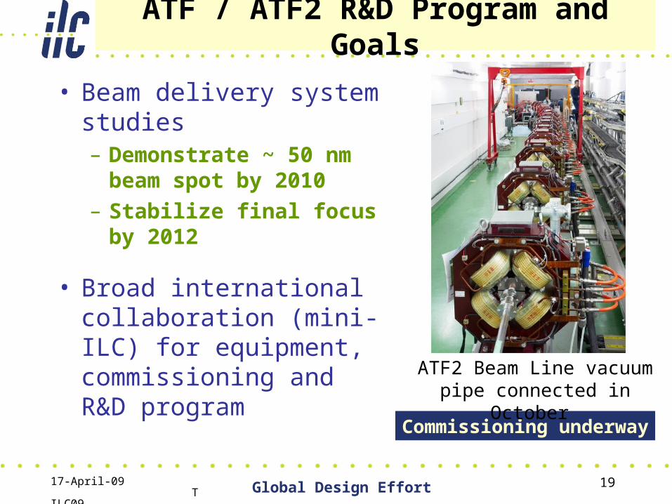
ATF / ATF2 R&D Program and Goals
• Beam delivery system studies– Demonstrate ~ 50 nm
beam spot by 2010– Stabilize final focus by
2012
• Broad international collaboration (mini-ILC) for equipment, commissioning and R&D program Commissioning underway
ATF2 Beam Line vacuum pipe connected in October
17-April-09 TILC09 Global Design Effort 20
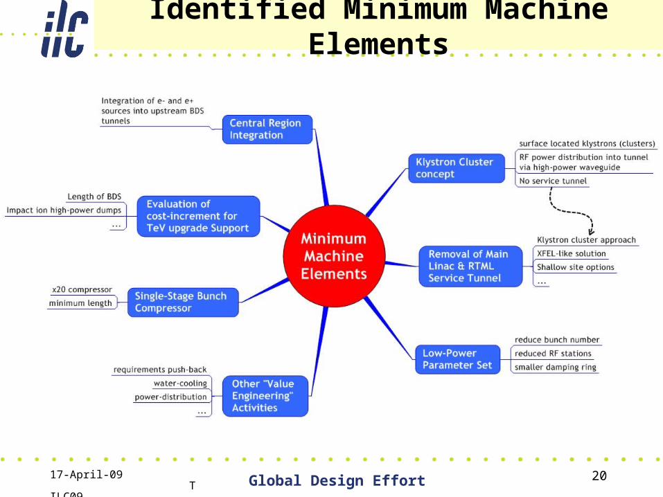
Identified Minimum Machine Elements
17-April-09 TILC09 Global Design Effort 21
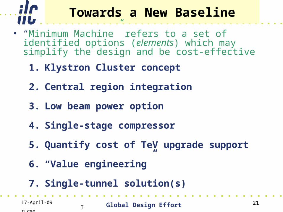
Towards a New Baseline
• “Minimum Machine” refers to a set of identified options (elements) which may simplify the design and be cost-effective
21
1. Klystron Cluster concept
2. Central region integration
3. Low beam power option
4. Single-stage compressor
5. Quantify cost of TeV upgrade support
6. “Value engineering”
7. Single-tunnel solution(s)
17-April-09 TILC09 Global Design Effort 22
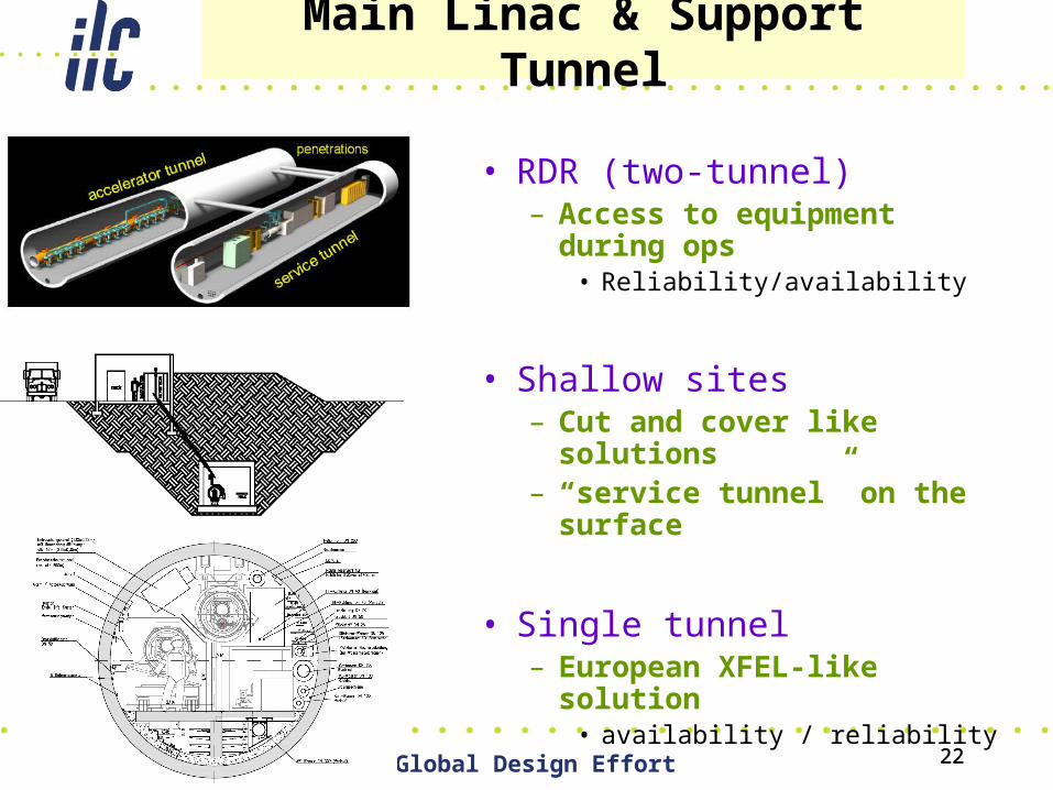
Main Linac & Support Tunnel
• RDR (two-tunnel)– Access to equipment during
ops• Reliability/availability
• Shallow sites– Cut and cover like solutions– “service tunnel” on the
surface
• Single tunnel– European XFEL-like solution
• availability / reliability
22
17-April-09 TILC09 Global Design Effort 23
Technical Design Phase and Beyond
MM studies
2009 2010
RDR ACD concepts
R&D Demonstrations
TDP Baseline Technical Design
2011 2012 2013
RDR Baseline
Ne
w b
ase
line
inp
uts
TDR
TDP-1 TDP-2 ChangeRequest
17-April-09 TILC09 Global Design Effort 24
Technical Design Report
• What will it be?– Cost performance optimized technical design– It will include new “value” estimate– It will include a project implementation plan
• Who will it be for?– It will be a detailed design and project plan ready
for serious consideration by potential collaborating governments.
• What it will not be?– It will not be a complete engineering design with
drawings, etc.
17-April-09 TILC09 Global Design Effort 25
Technical Design Report • What about LHC results?
– The LHC will need to be a success technically (energy, luminosity and duty cycle)
– LHC science will need to ‘validate’ the science case.
• Who about CLIC?– Joint work with CLIC will help make technical, cost
and readiness comparisons possible, if needed.– Will LHC points to a ~ 1 TeV machine?
• Will our job be done?– Continuing R&D demonstrations, ADC and
industrialization– Funding could become more difficult, without a
potential project is in sight.
17-April-09 TILC09 Global Design Effort 26
Technical Reviews
• Accelerator Advisory Panel (Willis & Elsen)– On-going reviews by assigned AAP members
to particular systems (attend meetings, etc) Example result: Questions regarding plug compatibility have resulted in studies, report
– Technical Review – first one 3.5 days at TILC09 in April. Internal + 4-5 external reviewers. Yearly through TDP phase with continuity. First review: Overall coverage + focus areas
• ILCSC PAC Review: – 1.5 days (1 day GDE); higher level review and
will use AAP review as input.
17-April-09 TILC09 Global Design Effort 27
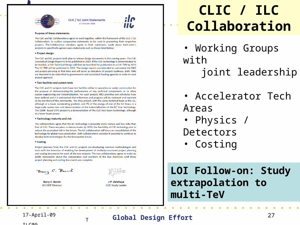
CLIC / ILCCollaboration
• Working Groups with joint leadership
• Accelerator Tech Areas• Physics / Detectors• Costing
• First progress reported last fall
LOI Follow-on: Study extrapolation to multi-TeV
17-April-09 TILC09 Global Design Effort 28
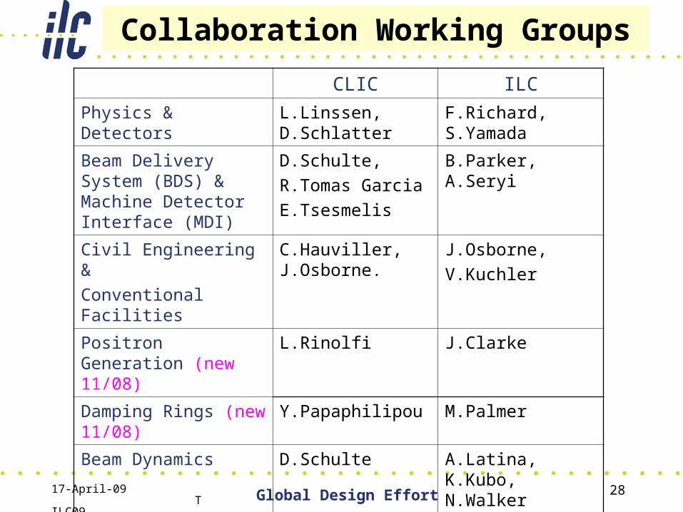
Collaboration Working Groups
CLIC ILC
Physics & Detectors L.Linssen, D.Schlatter
F.Richard, S.Yamada
Beam Delivery System (BDS) & Machine Detector Interface (MDI)
D.Schulte,
R.Tomas Garcia
E.Tsesmelis
B.Parker, A.Seryi
Civil Engineering &
Conventional Facilities
C.Hauviller, J.Osborne.
J.Osborne,
V.Kuchler
Positron Generation (new 11/08)
L.Rinolfi J.Clarke
Damping Rings (new 11/08)
Y.Papaphilipou M.Palmer
Beam Dynamics D.Schulte A.Latina, K.Kubo, N.Walker
Cost & Schedule H.Braun, K.Foraz, P. LeBrun
J.Carwardine, P.Garbincius, T.Shidara
17-April-09 TILC09 Global Design Effort 29
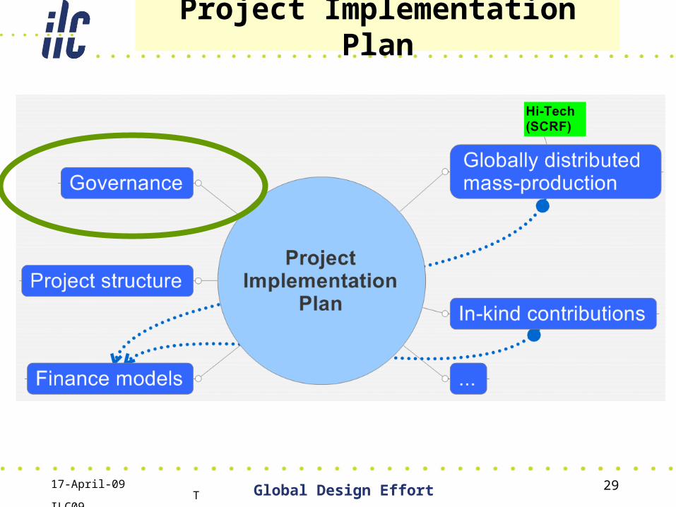
Project Implementation Plan
17-April-09 TILC09 Global Design Effort 30
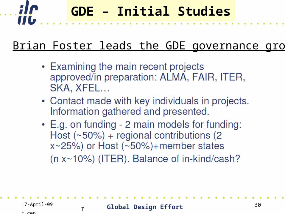
GDE – Initial Studies
• Brian Foster leads the GDE governance group
17-April-09 TILC09 Global Design Effort 31
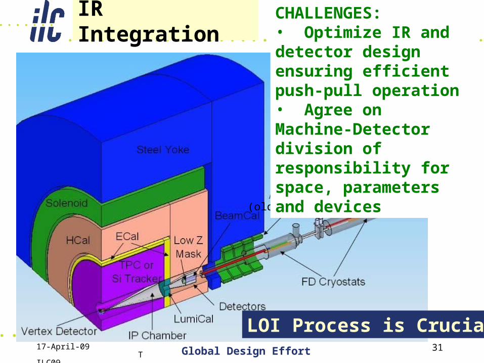
IR Integration
(old location)
CHALLENGES:• Optimize IR and detector design ensuring efficient push-pull operation• Agree on Machine-Detector division of responsibility for space, parameters and devices
LOI Process is Crucial
17-April-09 TILC09 Global Design Effort 32
Final Remarks
• We are on track to be able to propose the ILC on a time scale of ~2012 (or before!)– GDE R&D demonstrations– Cost/risk/performance optimized technical design – Project Implementation Plan – Detector LOIs Technical designs– LHC results– Outreach to generate support from science
community, funding agencies, etc
• Welcome! This meeting should be particularly interesting: first following LOIs; and first AAP review (or experiment)
Recommended