Read all safety rules and instructions carefully before operating this tool.
OPERATOR’S MANUALTOLL-FREE HELPLINE: 1-888-90WORKS (888.909.6757)
1700 PSI / 1.4 GPMELECTRIC PRESSURE WASHER
51012

2
Introduction .......................................................................................................................... 2Important Safety Instructions. .............................................................................................. 3Specific Safety Rules. .......................................................................................................4 -5Symbols ............................................................................................................................ 6 -7Electrical ...........................................................................................................................8 -9Know Your Pressure Washer. ............................................................................................ 10 Assembly .......................................................................................................................11-14Operation. ..................................................................................................................... 15-20Maintenance ................................................................................................................. 21-23Troubleshooting ............................................................................................................ 24-26Warranty ............................................................................................................................ 2 7Exploded View ................................................................................................................... 2 8
Part List ........................................................................................................................ 29-31
PRODUCT SPECIFICATIONS
Induction Motor ......................................................................... 120 V, 60 Hz, 13 Amps, 3-WireMax. Pounds Per Square Inch Pressure* ..................................................................... 1700 psiMax. Gallons Per Minute* ............................................................................................1,4 gpmMaximum Inlet Water Temperature .................................................................................. 104˚FUnit Weight .....................................................................................................46 lbs (20.9 kg)
TABLE OF CONTENTS

3
W A R N I N GRead and understand all instructions. Failure to follow all instructions listed below may result in electric shock, fire, and/or serious personal injury.
W A R N I N GWhen using this product basic precautions should always be followed, including the following:
READ ALL INSTRUCTIONS BEFORE USING THIS PRODUCT• To reduce the risk of injury, close supervision is necessary when a product is used near
children.• Be thoroughly familiar with controls. Know how to stop the product and release pressure
quickly.• Stay alert and exercise control. Watch what you are doing and use common sense. Do not
operate product when you are tired. Do not rush.• Do not operate the product while under the influence of drugs, alcohol, or any
medication.• Keep the area of operation clear of all persons, particularly small children, and pets.• Don’t overreach or stand on unstable support. Keep proper footing and balance at all times.• Follow the maintenance instructions specified in this manual.• This product is provided with a ground fault circuit interrupter built into the power cord
plug. If replacement of the plug or cord is needed, use only identical replacement parts.
W A R N I N GRisk of injection or injury – Do not direct discharge stream at people or animals.
GROUND FAULT CIRCUIT INTERRUPTER PROTECTION• This pressure washer is provided with a ground fault circuit interrupter (GFCI) built into the
plug of the power supply cord. This device provides additional protection from the risk of electric shock. Should replacement of the plug or cord become necessary, use only identical replacement parts that include GFCI protection.
SERVICING OF A DOUBLE-INSULATED APPLIANCE• In a double-insulated product, two systems of insulation are provided instead of grounding.
No grounding means is provided on a double-insulated product, nor should a means for grounding be added to the product. Servicing a double-insulated product requires extreme care and knowledge of the system, and should be done only by qualified service personnel. Replacement parts for a double insulated product must be identical to the parts they replace. A double-insulated product is marked with the words “DOUBLE INSULATION” or “DOUBLE INSULATED.” The symbol may also be marked on the product.
EXTENSION CORDS• Do not use with extension cord. Plug directly into receptacle.
W A R N I N GTo reduce the risk of electrocution, keep all connections dry and off the ground. Do not touch plug with wet hands.
IMPORTANT SAFETY INSTRUCTIONS

4
SPECIFIC SAFETY RULES
• Know your product. Read the operator’s manual carefully. Learn the machine’s applications and limitations as well as the specific potential hazards related to this product.
• To reduce the risk of injury, keep children and visitors away. All visitors should wear safety glasses and be kept a safe distance from work area.
• Use right product. Don’t force product or attachment to do a job it was not designed for. Don’t use it for a purpose not intended.
• Dress properly. Do not wear loose clothing, gloves, neckties, or jewelry. They can get caught and draw you into moving parts. Rubber gloves and nonskid footwear are recommended when working outdoors. Also wear protective hair covering to contain long hair.
• Do not operate the equipment while barefoot or when wearing sandals or similar lightweight footwear. Wear protective footwear that will protect your feet and improve your footing on slippery surfaces.
• Exercise caution to avoid slipping or falling.• Always wear eye protection with side shields marked to comply with ANSI Z87.1.
Following this rule will reduce the risk of serious personal injury.• Use only recommended accessories. The use of improper accessories may cause risk of
injury.• Check damaged parts. Before further use of the product, a guard or other part that is damaged
should be carefully checked to determine that it will operate properly and perform its intended function. Check for alignment of moving parts, binding of moving parts, breakage of parts, mounting, and any other conditions that may affect its operation. A guard or other part that is damaged must be properly repaired or replaced by an authorized service center to avoid risk of personal injury.
• Never leave product running unattended. Turn power off. Don’t leave product until it comes to a complete stop.
• Keep the motor free of grass, leaves, or grease to reduce the chance of a fire hazard.• Follow manufacturer’s recommendations for safe loading, unloading, transport, and
storage of machine.• Keep product dry, clean, and free from oil and grease. Always use a clean cloth when
cleaning. Never use brake fluids, gasoline, petroleum-based products, or any solvents to clean product.
• Check the work area before each use. Remove all objects such as rocks, broken glass, nails, wire, or string which can be thrown or become entangled in the machine.
• Do not use product if switch does not turn it off. Have defective switches replaced by an authorized service center.
• Avoid dangerous environment. Don’t expose to rain. Keep work area well lit.• Do not abuse the cord. Never use the cord to carry the product or to disconnect the plug from
an outlet. Keep cord away from heat, oil, sharp edges, or moving parts. Replace damaged cords immediately. Damaged cords increase the risk of electric shock.
• Ground Fault Circuit Interrupter (GFCI) protection should be provided on the circuit(s) or outlet(s) to be used for the product. Receptacles are available having built-in GFCI protection and may be used for this measure of safety.
• Never direct a water stream toward people or pets, or any electrical device.• Before starting any cleaning operation, close doors and windows. Clear the area to be
cleaned of debris, toys, outdoor furniture, or other objects that could create a hazard.• Do not use acids, alkalines, solvents, flammable material, bleaches, or industrial grade
solutions in this product. These products can cause physical injuries to the operator and irreversible damage to the machine.
5
SPECIFIC SAFETY RULES
W A R N I N GHigh pressure jets can be dangerous if subject to misuse. The jet must not be directed at people, animals, electrical devices, or the machine itself.
• Keep the motor away from flammables and other hazardous materials.• Check bolts and nuts for looseness before each use. A loose bolt or nut may cause serious
motor problems.• Before storing, allow the motor to cool.• When servicing use only identical replacement parts. Use of any other parts may create a
hazard or cause product damage.• ONLY use cold water.• Make sure minimum clearance of 3 feet is maintained from combustible materials.• Connect pressure washer only to an individual branch circuit.• Hold the handle and wand securely with both hands. Expect the trigger handle to move
when the trigger is pulled due to reaction forces. Failure to do so could cause loss of control and injury to yourself and others.
• Save these instructions. Refer to them frequently and use them to instruct other users. If you loan someone this product, loan them these instructions also.
W A R N I N GSome dust created by power sanding, sawing, grinding, drilling, and other construction activities contains chemicals known to cause cancer, birth defects or other reproductive harm. Some examples of these chemicals are:• Lead from lead-based paints• Crystalline silica from bricks and cement and other masonry products• Arsenic and chromium from chemically-treated lumber. Your risk from these exposures varies,
depending on how often you do this type of work. To reduce your exposure to these chemicals: work in a well ventilated area, and work with approved safety equipment, such as those dust masks that are specially designed to filter out microscopic particles.
SAVE THESE INSTRUCTIONS

6
SYMBOL NAME DESIGNATION/EXPLANATION
V Volts Voltage
A Amperes Current
Hz Hertz Frequency (cycles per second)
W Watt Power
no No Load Speed Rotational speed, at no load
Alternating Current Type of current
.../min Per Minute Revolutions, strokes, surface speed, orbits etc., per minute
Class II Construction Double-insulated construction
Safety Alert Indicates a potential personal injury hazard.
To reduce the risk of injury, user must read and Read Operator’s Manual understand operator’s manual before using this product.
Eye Protection Always wear eye protection with side shields marked to comply with ANSI Z87.1.
Wet Conditions Alert Do not expose to rain or use in damp locations.
To reduce the risk of injection or injury, never direct a water stream towards people or pets or Risk of Injection place any body part in the stream. Leaking hoses and fittings are also capable of causing injection injury. Do not hold hoses or fittings.
Kickback To reduce the risk of injury from kickback, hold the spray wand securely with both hands when the machine is on.
Electric Shock Failure to use in dry conditions and to observe safe practices can result in electric shock.
Some of the following symbols may be used on this product. Please study them and learn their meaning. Proper interpretation of these symbols will allow you to operate the product better and safer.
SYMBOLS

7
SYMBOLS
SYMBOL NAME DESIGNATION/EXPLANATION
To reduce the risk of injury or damage, DO NOT USE ACIDS, ALKALINES,BLEACHES, Chemical Burns SOLVENTS, FLAMMABLE MATERIAL, OR INDUSTRIAL GRADE SOLUTIONS in this product.
SYMBOL SIGNAL MEANING
DANGER Indicates an imminently hazardous situation, which, if not avoided, will result in death or serious injury.
WARNING Indicates a potentially hazardous situation, which, if not avoided, could result in death or serious injury.
CAUTION Indicates a potentially hazardous situation, which, if not avoided, may result in minor or moderate injury.
CAUTION (Without Safety Alert Symbol) Indicates a situation that may result in property damage.
The following signal words and meanings are intended to explain the levels of risk associated with this product.
SERVICEServicing requires extreme care and knowledge and should be performed only by a qualified service technician. For service we suggest you return the product to your nearest AUTHORIZED SERVICE CENTER for repair. When servicing, use only identical replacement parts.
W A R N I N GTo avoid serious personal injury, do not attempt to use this product until you read thoroughly and understand completely the operator’s manual. If you do not understand the warnings and instructions in the operator’s manual, do not use this product. Call GREENWORKS customer service for assistance.
W A R N I N GThe operation of any power tool can result in foreign objects being thrown into your eyes, which can result in severe eye damage. Before beginning power tool operation, always wear safety goggles or safety glasses with side shields and, when needed, a full face shield. We recommend Wide Vision Safety Mask for use over eyeglasses or standard safety glasses with side shields. Always use eye protection which is marked to comply with ANSI Z87.1.

8
ELECTRICAL
NOTE: Servicing of a product with double insulation requires extreme care and knowledge of the system and should be performed only by a qualified service technician. For service, we suggest you return the product to your nearest authorized service center for repair. Always use original factory replacement parts when servic-ing.
ELECTRICAL CONNECTION
This product has a precision-built electric motor. It should be connected to a power supply that is 120 volts, AC only (normal household current), 60 Hz. Do not operate this product on direct current (DC). A substantial voltage drop will cause a loss of power and the motor will overheat. If the product does not operate when plugged into an outlet, double-check the power supply.
DRIP LOOP (See Figure 1.)
To prevent water from flowing along the power cable, and possibly reaching the electrical outlet and plug, we recommend using a simple drip loop as shown below.
Fig. 1
Pressure washer power cord
Drip loop
W A R N I N GThe double insulated system is intended to protect the user from shock resulting from a break in the product’s internal insulation. Observe all normal safety precautions to avoid electrical shock.
DOUBLE INSULATEDDouble insulation is a concept in safety in electric power tools, which eliminates the need for the usual three-wire grounded power cord. All exposed metal parts are isolated from the internal metal motor components with protecting insulation. Double insulated products do not need to be grounded.
9
ELECTRICAL
W A R N I N GKeep the cord clear of the working area. Position the cord so that it will not get caught on lumber, tools, or other obstructions while you are working with a power tool. Failure to do so can result in serious personal injury.
W A R N I N GDouble insulation is a concept in safety in electric power tools, which eliminates the need for the usual three-wire grounded power cord. All exposed metal parts are isolated from the internal metal motor components with protecting insulation. Double insulated products do not need to be grounded.
GROUND FAULT CIRCUIT INTERRUPTERThis unit is equipped with a Ground Fault Circuit Interrupter (GFCI), which guards against the hazards of ground fault currents. An example of ground fault current is the current that would flow through a person who is using an appliance with faulty insulation and, at the same time, is in contact with an electrical ground such as a plumbing fixture, wet floor, or earth.
GFCI plugs do not protect against short circuits, overloads, or shocks.
To test:
• Depress the TEST button. This should cause the RESET button to pop out.• To restore power, depress the RESET button.
Perform this test monthly to ensure proper operation of the GFCI.
W A R N I N GTO PROTECT AGAINST ELECTRIC SHOCK TEST BEFORE EACH USE
• PLUG INTO RECEPTACLE• IF LIGHT IS NOT ON, PRESS RESET BUTTON-LING SHOULD COME ON• PRESS TEST BUTTON-LIGNT MUST GO OFF• PRESS RESET BUTTON AGAIN FOR USEDO NOT USE IF TEST FAILSDO NOT USE AN EXTENSION CORD TO SUPPLY POWER TO THIS DEVICERAINPROOFDO NOT IMMERSE

10
KNOW YOUR PRESSURE WASHER
The safe use of this product requires an understanding of the information on the tool and in this operator’s manual as well as a knowledge of the project you are attempting. Before use of this product, familiarize yourself with all operating features and safety rules. (See Figure 2.)
Fig. 2
DETERGENT TANK Remove the cap from the detergent tank to add detergent to the pressure washer.
GFCI PLUGThe pressure washer is equipped with a GFCI plug to guard against the hazards of ground fault currents. This plug does not protect against short circuits, overloads, or shocks.
HIGH PRESSURE HOSE STORAGE REEL A convenient hose reel stores the high pressure hose when the pressure washer is not in use.
ON / OFF SWITCH This switch turns the pressure washer on and off.
POWER CORD STORAGE REELStore the power cord on the convenient storage reel when the pressure washer is not in use. Rotate the reel face counter-clockwise and remove for quick release of the cord.
FOLDING HANDLEThe folding handle allows the handle to be lowered for convenient storage.
TRIGGER HANDLE The trigger handle has a gripping surface that provides added control of the spray wand and helps reduce fatigue.
TRIGGER WITH LOCK-OUT Pulling the trigger releases a stream of water for high pressure cleaning. The lock-out provides protection against unauthorized use.
Spray wand
High pressure hose
Detergent tank
Wheels
High pressure hose storage reel
On/Off switch
Water hose intake
TriggerHandle assembly
Nozzle storage bar
Release button

11
ASSEMBLY
UNPACKINGThis product requires assembly.
• Carefully remove the product and any accessories from the box. Make sure that all items listed in the packing list are included.
W A R N I N GDo not use this product if any parts on the Packing List are already assembled to your product when you unpack it. Parts on this list are not assembled to the product by the manufacturer and require customer installation. Use of a product that may have been improperly assembled could result in serious personal injury.
• Inspect the product carefully to make sure no breakage or damage occurred during shipping.
• Do not discard the packing material until you have carefully inspected and satisfactorily operated the product.
• If any parts are damaged or missing, please call 1-888-909-6757 for assistance.
PACKING LIST• Pressure Washer with 25 ft. High Pressure Hose
• Operator’s manual
• Spray gun
• Lance
• Quick release velcro strap
• Net bag
• Turbo nozzle (0°, 25°, 40°, 75° nozzles)
W A R N I N GIf any parts are damaged or missing do not operate this product until the parts are replaced. Use of this product with damaged or missing parts could result in serious personal injury.
W A R N I N GDo not attempt to modify this product or create accessories not recommended for use with this product. Any such alteration or modification is misuse and could result in a hazardous condition leading to possible serious personal injury.
W A R N I N GDo not connect to power supply until assembly is complete. Failure to comply could result in accidental starting and possible serious personal injury.
12
ASSEMBLY
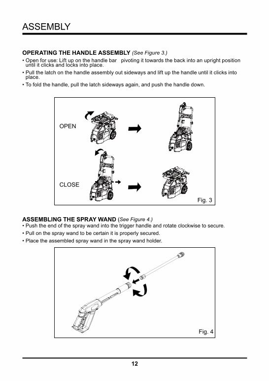
OPERATING THE HANDLE ASSEMBLY (See Figure 3.)• Open for use: Lift up on the handle bar pivoting it towards the back into an upright position
until it clicks and locks into place.• Pull the latch on the handle assembly out sideways and lift up the handle until it clicks into
place.• To fold the handle, pull the latch sideways again, and push the handle down.
ASSEMBLING THE SPRAY WAND (See Figure 4.)• Push the end of the spray wand into the trigger handle and rotate clockwise to secure.• Pull on the spray wand to be certain it is properly secured.• Place the assembled spray wand in the spray wand holder.
Fig. 4
Fig. 3
OPEN
CLOSE

13
ASSEMBLY
Fig. 5
CONNECTING HIGH PRESSURE HOSE TO TRIGGER HANDLE (See Figure 5.)• Slide the hose lock forward to open.• Connect the high pressure hose to the trigger handle. Insert high pressure hose into trigger
handle.

14
Fig. 6
AB A- Garden hose
B-Water intake
CONNECTING THE GARDEN HOSE (See Figure 6.)
C A U T I O N :Always observe all local regulations when connecting hoses to the water main. Some areas have restrictions against connecting directly to public drinking water supply to prevent the feedback of chemicals into the drinking water supply. Direct connection through a receiver tank or backflow preventer is usually permitted.
Connect garden hose to pressure washer water intake.• Uncoil the garden hose.NOTE: There must be a minimum of 10 feet of unrestricted garden hose between the water intake and the garden hose faucet or shut off valve (such as a “Y” shut off connector).• Run water through the garden hose for 30 seconds to clean any debris from the hose.• Inspect the screen in the water intake.• If the screen is damaged, do not use the machine until the screen has been replaced.• If the screen is dirty, clean it before connecting the garden hose to the machine.• With the hose faucet turned completely off, attach the end of the garden hose to the water
intake. Tighten by hand.
ASSEMBLY
15
OPERATION
W A R N I N GDo not allow familiarity with the product to make you careless. Remember that a careless fraction of a second is sufficient to inflict serious injury.
W A R N I N GAlways wear eye protection with side shields marked to comply with ANSI Z87.1. Failure to do so could result in objects being thrown into your eyes resulting in possible serious injury.
W A R N I N GDo not use any attachments or accessories not recommended by the manufacturer of this product. The use of attachments or accessories not recommended can result in serious personal injury.
W A R N I N GNever direct a water stream toward people or pets, or any electrical device. Failure to heed this warning could result in serious injury.
APPLICATIONSYou may use this product for the purposes listed below:• Cleaning boats, cars, trucks, motorcycles, outdoor furniture, grills, house siding, driveways,
patios and decks.

16
OPERATION
Fig. 7-1
Fig. 7-2
Fig. 7-3
BA
DETERGENT ADDING AND USE (See Figure 7-1.)Use only detergents designed for pressure washers; household detergents, acids, alkalines, bleaches, solvents, flammable material, or industrial grade solutions can damage the pump. Many detergents may require mixing prior to use. Prepare cleaning solution as instructed on the solution bottle.
To add:• Disconnect pressure washer from power supply.• Place pressure washer upright on a flat surface.• Remove cap from detergent tank.• Pour detergent into tank.To use:
C A U T I O NUse only approved pressure washer cleaners. Do not use bleach, chlorine,or any cleaners containing acids.
The dial is used to control the suction between detergent tanks and increase/decrease detergent flow.• Turn dial to choose the desired tank.(See Figure 7-2.)• Connect black 75° soap nozzle to the wand connector.(See Figure 7-3.)• Squeeze the trigger and the detergent will automatically be mixed with the water and dispensed
from the nozzle.NOTE: Use a funnel, if needed, to prevent accidental spilling of the detergent outside the tank. If any deter-gent is spilled during the filling process, make sure the unit is cleaned and dried before proceeding.• Reinstall cap.

17
OPERATION
PUMP LUBRICANTThe pressure washer pump has been filled with sufficient lubricant at the factory and is mainte-nance free. You do not need to check or add lubricant to the pump before initial use.
STARTING AND STOPPING THE PRESSURE WASHER (See Figure 8.)
C A U T I O N :Do not run the pump without the water supply connected and turned on.
• Connect the garden hose.• Turn the garden hose on then squeeze the trigger to relieve air pressure. Once a steady stream
of water appears,release the trigger.
Fig. 8
• After ensuring the On/Off switch is in the OFF ( O ) position,connect the pressure washer to the power supply.
• Press the reset button on the pressure washer’s plug to make sure the unit is ready for operation.
• Press ON ( I ) on the switch to start the motor.• To stop the motor, release the trigger and press OFF( O ) on the switch.
NOTE: The pressure washer may be on and the system may have pressure even when the pump and/or motor cannot be heard running. Always use caution around the pressure washer.
W A R N I N GHold the trigger handle securely with both hands. Expect the trigger handle to move when the trigger is pulled due to reaction forces. Failure to do so could cause loss of control and injury to yourself and others.
On/off switch

18
OPERATION
Fig. 9
1
2 2
3 3
Spray wand
Turbo nozzle
1-Pull back the quick-connect collar
2-Push the nozzle into place
3-Push the collar forward
Nozzle
USING THE NOZZLES (See Figure 9.)Each of the nozzles has a different spray pattern. Before starting any cleaning job, determine the best nozzle for the job. The following chart offers some general guidelines to help you choose the best nozzle for your application.NOTE: Always try nozzles in an inconspicuous area first.
Red - Stream nozzle (0° )• The Red 0 degree tip provides a straight line of spray. It provides the
highest amount of pressure. It is best used for removing hard, stuck-on grime or dirt.
Green - Narrow fan tip (25° )• The Green pressure washer tip provides high versatility with its 25
degree angle tip. Referred to as the washing tip, because it provides adequate pressure to remove dirt from surfaces, but is designed to not damage many surfaces. This pressure washer tip is designed for “sweeping” foliage or debris given its wide angle. This tip is versatile due to its wide area of cleaning and strong pressure application.
NOZZLE APPLICATION
25O
0O

19
OPERATION
White - Wide fan tip (40° )• The white 40 degree tip, referred to as the “fan” tip creates the
widest area of cleaning with relatively low pressure. This pressure washer tip is best used for light or delicate cleaning applications. It is recommended for light cleaning on wood decks and other soft or delicate surfaces.
Black - Soap nozzle tip (75° )• The black 75 degree tip, referred to as the low pressure nozzle. This
is for use with soap application.Turbo Nozzle Tip• The nozzle rotates in a zero degree spray pattern in a circular
motion to break down tough dirt and grime. The spray pattern can cover area of 4 to 8 inches wide, depending on a distance between the tip and the surface being cleaned.
NOZZLE APPLICATION
W A R N I N GNEVER change nozzles without engaging the lock-out on the trigger handle and NEVER point the wand at your face or at others. The quick-connect feature contains small springs that could eject the nozzle with some force. Failure to heed this may cause personal injury.
• Turn off the pressure washer and shut off the water supply.Pull trigger to release water pressure.
• Engage the lock-out on the trigger handle by pushing the trigger lock button to the right.• Pull back the quick-connect collar.• Push the nozzle into place in the spray wand.• Push the collar forward so that the nozzle is secured properly. Check to see that the nozzle is
secure.TO DISCONNECT A NOZZLE FROM THE TRIGGER HANDLE ONCE THE CLEANING jOB IS COMPLETE:• Turn off the pressure washer and shut off the water supply. Pull trigger to release water
pressure.• Engage the lock-out on the trigger handle by pushing the trigger lock button to the right.• Remove the nozzle by placing hand over nozzle then pulling back the quick-connect collar.
Place nozzle in the nozzle storage area on the trigger handle.
75O
40O

20
OPERATION
To clean:• Pour detergent in the detergent tank.• Install the black soap nozzle on the spray wand.• Start the pressure washer and spray the detergent on a dry surface using long, even,
overlapping strokes. To prevent streaking, do not allow detergent to dry on the surface.To rinse:• Using the 25˚ nozzle, spray away from the rinsing surface for approximately 10 seconds to
allow any remaining detergent to be flushed from the line.• Start at the top of the area to be rinsed and work down, overlapping the strokes.MOVING THE PRESSURE WASHERTo move the pressure washer:• Turn the pressure washer off. Point nozzle in a safe direction and pull trigger to release water
pressure.• Raise the handle up until the buttons click into the holes on the handle.• Tilt the machine toward you until it balances on the wheels then roll the machine to the
desired position.
Fig. 10
OPERATING THE PRESSURE WASHER (See Figure 10.)Use only detergents designed for pressure washers. Many detergents may require mixing prior to use. Prepare cleaning solution as instructed on the solution bottle.
21
MAINTENANCE
W A R N I N GWhen servicing, use only identical replacement parts. Use of any other parts may create a hazard or cause product damage.
W A R N I N GAlways wear eye protection with side shields marked to comply with ANSI Z87.1. Failure to do so could result in objects being thrown into your eyes, resulting in possible serious injury.
W A R N I N GBefore inspecting, cleaning or servicing the machine, shut off engine, wait for all moving parts to stop, disconnect unit from power supply, and pull trigger to release water pressure. Failure to follow these instructions can result in serious personal injury or property damage.
GENERAL MAINTENANCE Avoid using solvents when cleaning plastic parts. Most plastics are susceptible to damage from various types of commercial solvents and may be damaged by their use. Use clean cloths to remove dirt, dust, oil, grease, etc.
W A R N I N GDo not at any time let brake fluids, gasoline, petroleum-based products, penetrating oils, etc., come in contact with plastic parts. Chemicals can damage, weaken or destroy plastic which may result in serious personal injury..
Only the parts shown on the parts list are intended to be repaired or replaced by the customer. All other parts should be replaced at an authorized service center.

22
MAINTENANCE
NOZZLE MAINTENANCE (See Figure 11.)Excessive pump pressure (a pulsing sensation felt while squeezing the trigger) may be the result of a clogged or dirty nozzle.• Unplug the pressure washer.• Turn off the pressure washer and shut off the water supply. Pull trigger to release water
pressure.• Remove the nozzle from the spray wand.NOTE: Never point the spray wand at your faceUsing a straightened paper clip or nozzle cleaning tool (not provided), free any foreign materials clogging or restricting the nozzle.• Using a garden hose, flush debris out of nozzle by back flushing (running the water through the
nozzle backwards or from the outside to the inside).• Reconnect the nozzle to the spray wand.• Turn on the water supply.
Fig. 11
STORING THE PRESSURE WASHERStore in a dry, covered area where the weather can’t damage it.It is important to store this product in a frost-free area. Always empty water from all hoses, the pump, and the detergent container before storing.NOTE: Use of a pump saver will give you better performance and increase the life of the machine.
QUICK WINTERIZING PROCEDUREIf you cannot do the Optimum Winterizing procedure, you can still protect your pressure washer from winter from winter-damage by doing below:• Disconnect all water connections.• Turn on the machine for a few second, unit the remaining water in the pump exits. Turn off
immediately.• Do not allow high-pressure hose to become kinked.• Store the machine and accessories in a room that does not reach freezing temperatures.Do
not store near furnace or other sources of heat as it may dry out the pump seals.
C A U T I O N :Drain gun assembly of any remaining water. Aim gun downwards and squeeze trigger.

23
MAINTENANCE
SHUTTING DOWN AND CLEANING UP• (if you are not using detergent, go directly to Step 2.) When you have finished using the
detergent injection system, fill detergent bottle with clean water. Siphon water at low-pressure for one minute so that all detergent is flushed through system. Remove detergent bottle and rinse it thoroughly.
• Disconnect the garden hose from the water inlet on the unit.• Press trigger to release any remaining water pressure.• Turn the switch to "OFF" (0) position.• Unplug the power cord from the outlet.• Engage gun safety lock.
W A R N I N GTurn off water supply and squeeze trigger to depressurize the unit. Failure to do so could result in personal injury due to discharge of high-pressure water.
TAKING A BREAKIf taking a break of five minutes or more.• Engage gun safety lock.• Turn unit to “OFF” (O) position.• Unplug the power cord from the outlet.
C A U T I O N :The use of a pump protector is recommended to prevent cold weather damage during storage over the winter months.

24
TROUBLESHOOTING
PROBLEMMotor will not start.
Unit does not reachhigh pressure.
Output pressure varies high and low.
POSSIBLE CAUSEOn/Off switch is in the“OFF” (O) position.
Power cord is not plugged in.
Electrical outlet does not sup-ply adequate power.
Tripped pressure washer circuit breaker
Diameter of garden hose is too small.
Water supply is restricted.
Not enough water supply.
Water inlet filter is clogged.
Power nozzle is in low-pressure position.
Pump is sucking air.
Not enough inlet water supply.
Pump is sucking air.
Water inlet filter is clogged.
SOLUTIONTurn switch to the “ON”( | ) position.
Plug in power cord.
Try a different outlet.
Allow to cool, and restart unit.
Replace with a 1” (25 mm) or 5/8” (16 mm) garden hose.
Check garden hose for kinks, leaks and blockage.
Open water source fully.
Remove filter and rinse in warm water.
Turn power nozzle to high-pressure position.
Check that hoses and fittings are airtight. Turn “OFF” machine, and purge pump by squeezing trigger gun until a steady flow of water emerges through the nozzle.
Turn water on fully. Check garden hose for kinks, leaks or blockage
Check that hoses and fittings are airtight. Turn “OFF” machine, and purge pump by squeezing trigger gun until a steady flow of water emerges through the nozzle.
Remove filter and rinse with warm water.

25
TROUBLESHOOTING
PROBLEMOutput pressure varies high and low. (contin-ued)
Unit does not reachhigh pressure.
Pump is noisy
Water leaks from pump (up to 10 drops per min-ute is permissible).
Oil is dripping
Spray wand, extension, or nozzle leaks.
Garden hose connection leaks.
POSSIBLE CAUSEDischarge nozzle is ob-structed.
Calcified gun, hose or power nozzle.
Diameter of garden hose is too small.
Detergent bottle or suction tube not properly connected.
Detergent is too thick.
Filter on detergent suction tube is clogged.
Damaged or clogged deter-gent suction tube.
Nozzle is in high-pressure position.
Discharge nozzle is ob-structed.
Pump is sucking air
Water filter is clogged.
Loose fittings.
Water seals are damaged or worn.
Oil seals are damaged or worn.
Broken o-ring or plastic insert.
Loose fittings.
Missing/worn rubber washer.
SOLUTIONBlow out or remove debris with a fine needle.
Run distilled vinegar through detergent tank.
Add more detergent.
Check connections.
Dilute detergent.
Run warm water through filter to remove build-up.
Remove obstruction or replace detergent suction tube.
Turn nozzle tip to low-pressureposition.
Blow out or remove debris with a fine needle.
Check that hoses and fittings are airtight. Turn off machine and purge pump by squeezing trigger gun until a steady flow of water emerges through the nozzle.
Remove water filter and rinse in warm water.
Check that all fittings are tight.
Call the Toll-Free Hotline
Call the Toll-Free Hotline
Tighten fittings.
Insert new washer.
Call the Toll-Free Hotline.

26
TROUBLESHOOTING
PROBLEMMotor buzzes but fails to run.
No Water
POSSIBLE CAUSESupply voltage below mini-mum.
System has residual pres-sure.
Voltage loss due toextension cord.
Pressure washer not used for long periods.
Residual friction among com-ponents. Unit might hum.
Quick connect assembly is attached in reverse.
Water supply is OFF.
Kink in the garden hose.
SOLUTIONVerify that only the pressure washer is running on this circuit.
Turn unit “OFF”, squeeze trigger on spray wand to release pres-sure, then turn unit “ON”
Unplug any extension cords at-tached and plug the unit directly into the outlet.
Call the Toll-Free Hotline.
Disconnect water supply and power ON for 2 to 3 seconds, repeat couple times or until the motor starts.
Verify that Inlet adapter (G2) is attached to machine’s water inlet and that the quick connect coupler (G1) is attached to garden hose.
Turn ON water supply.
Remove kink in garden hose.
27
GREENWORKS™ hereby warranties this product, to the original purchaser with proof of purchase, for a period of one (1) years against defects in materials, parts or workmanship. GREENWORKS™, at its own discretion will repair or replace any and all parts found to be defective, through normal use, free of charge to the customer. This warranty is valid only for units which have been used for personal use that have not been hired or rented for industrial/commercial use, and that have been maintained in accordance with the instructions in the owners’ manual supplied with the product from new.
ITEMS NOT COVERED BY WARRANTY: 1. Any part that has become inoperative due to misuse, commercial use, abuse, neglect,
accident, improper maintenance, or alteration; or
2. The unit, if it has not been operated and/or maintained in accordance with the owner's manual; or
3. Normal wear, except as noted below;
4. Routine maintenance items such as draining the water to avoid freezing/ice damage to pump and components.
5. Normal deterioration of the exterior finish due to use or exposure.
GREENWORKS HELPLINE (1-888-90WORKS): Warranty service is available by calling our toll-free helpline, 9am to 5pm EST. Monday – Friday at 1-888-909-6757 (1-888-90WORKS).
TRANSPORTATION CHARGES: Transportation charges for the movement of any power equipment unit or attachment are the responsibility of the purchaser. It is the purchaser’s responsibility to pay transportation charges for any part submitted for replacement under this warranty unless such return is requested in writing by GREENWORKS.
WARRANTY
28
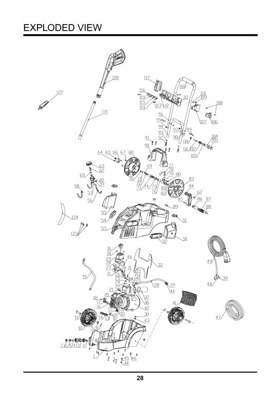
EXPLODED VIEW
29
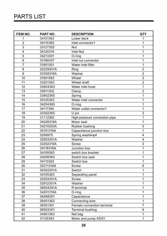
ITEM NO. PART NO. DESCRIPTION QTY 1 34101363 Lower deck 1 2 34115365 Inlet connector1 1 3 33127302 Nut 1 4 34124319 Inlet Nut 1 5 34213301 O-ring 1 6 33166307 Inlet nut connector 1 7 31901301 Water inlet filter 1 8 32229301A Ring 2 9 32308316A Washer 2 10 31901363 Wheel 2 11 33201363 Wheel shaft 2 12 34904363 Water inlet hose 1 13 33911302 Clamp 2 14 33902365 Spring 1 15 34125363 Water inlet connector 1 16 34204365 O-ring 1 17 34117365 Water outlet connector1 1 18 33302365 U pin 3 19 31112363 High-pressure connection pipe 1 20 34226316A Motor seal 1 21 34210303A Rubber bushing 5 22 34101316A Capacitance junction box 1 23 3290675 Spring washerφ4 4 24 32903301A Washer 4 25 32202316A Screw 3 26 34118316A Junction box 1 27 34109363 switch box bracket 1 28 34206363 Switch box seal 1 29 34110363 Switch box 1 30 32211316A Screw 6 31 36302301A Switch 1 32 34105363 Separating panel 1 33 32204301A Screw 1 34 32912301A Washer 1 35 36504301A R terminal 1 36 34201316A O-ring 1 37 36488301 Capacitance 1 38 36401363 Connecting wire 1 39 36501301 Female connection terminal 7 40 36503301 Terminal bushing 6 41 34901363 Net bag 1 42 31125363 Motor and pump ASSY 1
PARTS LIST

30
PARTS LIST
ITEM NO. PART NO. DESCRIPTION QTY 43 34120319 Power cord clamp 1 44 32203319 bolt 4 45 32913301A Washer 4 46 32201363 Screw 12 47 31120363 HP hose ASSY 1 48 36502301 Terminal 4 49 31102319 Power cord w. GFCI 1 50 34106363 Right tank 1 51 34201363 Tank cap 2 52 34104363 Right panel 1 53 34102363 Upper deck 1 54 34103363 Left panel 1 55 34107363 Left tank 1 56 34902363 Suction hose 3 57 34117363 Suction bushing 1 58 34905363 Suction hose 2 1 59 33302363 Suction U pin 1 60 34204363 Suction Seal 1 61 34216302 O-ring 2 62 34118363 Suction rotor 1 63 34116363 Suction knob 1 64 32258301A Pin 1 65 32905363 Shaft nut 1 66 33205363 Al Adapt connector 1 67 32205316A Screw 4 68 34122363 Left reel panel 1 69 34207363 O-ring 1 70 34208363 Rubber Ring 1 71 34210363 O-ring 1 72 34209363 Rubber Ring 1 73 33204363 Al Shaft 1 74 33326319 Shaft clamp 2 75 34218319 O-ring 2 76 34217319 Clamp 2 77 33217319 HP connector 1 78 34209319 O-ring 1 79 33327319 HP connection Rotor 1 80 33301363 Reel Pin 1 81 34238302A O-ring 1 82 32204363 Bolt 1 83 34121363 Right reel Panel 1 84 34123363 Reel Shaft 1

31
PARTS LIST
ITEM NO. PART NO. DESCRIPTION QTY 85 33203363 Reel pin 1 86 34124363 Reel shaft 1 87 34126363 Reel handle 1 88 34127363 Reel Nut 1 89 34113365 Ring 2 90 34108363 Handle 1 91 3220335 Screw 4 92 32202363 Bolt 2 93 32901363 Washer 2 94 33303365 Lower pull rod 1 95 34115363 Pull rod head 1 96 33202363 Upper pull rod 1 97 32201100 Lock Nut 2 98 33305365 Washer 2 99 33204365 Pull rod shaft 2 100 33205365 Nut 1 101 33207365 Pin 1 102 33901365 Pin spring 1 103 33206365 Pin seat 1 104 34118365 Pin bushing 1 105 34119365 Pin cap 1 106 34120365 Wand Hook 1 107 34121365 Gun handle hook 1 108 3220108 Screw 2 109 32902363 Nut 2 110 32903363 Washer 4 111 34111363 Nozzle store 1 112 34203363 Nozzle bushing 4 113 32203363 Screw 2 114 31203363 40 degree nozzle 1 115 31204319 25 degree nozzle 1 116 31201363 0 degree nozzle 1 117 34112363 Gun holder 1 118 34202363 Foam grip 1 119 31205319 Soap nozzle(75 degree nozzle) 1 120 31201365 Gun handle ASSY 1 121 31202365 Wand ASSY 1 122 31201301A Turbo nozzle 1 123 36511154A Junction cap 3 124 3030175 Heat-shrinkable tubing Φ6 5

Printed in China on 100% Recycled PaperRev: 01 (08-03-10)
TOLL-FREE HELPLINE: 1-888-90WORKS (888.909.6757)
Recommended