2-in-1 Transformer Test System
6235/7620/F7721
User Manual
Safety
General
This equipment has been designed to meet the requirements of EN61010-1 „Safety
requirements for electrical equipment for measurement, control & laboratory use‟ and
has left the factory in a safe condition.
The following definitions in EN61010-1 are applicable:
OPERATOR Person operating equipment for its intended purpose.
Note: The OPERATOR should have received training
appropriate for this purpose.
RESPONSIBLE BODY Individual or group responsible for the use and maintenance
of equipment and for ensuring that operators are adequately
trained.
The RESPONSIBLE BODY must ensure that this equipment is only used in the
manner specified. If it is not used in such a manner, the protection provided by the
equipment may be impaired.
This product is not intended for use in atmospheres which are explosive, corrosive or
adversely polluted (e.g. containing conductive or excessive dust). It is not intended for
use in safety critical or medical applications.
The equipment can cause hazards if not used in accordance with these instructions.
Read them carefully and follow them in all respects.
Do not use the equipment if it is damaged. In such circumstances the equipment
must be made inoperative and secured against any unintentional operation.
MICROTEST CORP. and the associated sales organizations accept no
responsibility for personal or material damage, or for any consequential damage
that results from irresponsible or unspecified operation or misuse of this
equipment.
Contents
CHAPTER 1. Before Use
1.1 Electric Shock Avoidance
1.2 Static Electricity
1.3 Grounding
1.4 AC Power Supply
1.5 Connecting Test Leads
1.6 Warm Up
1.7 External Control
1.8 Malfunction
1.9 Switch the Unit off
1.10 Preservation
1.11 In case of emergency
CHAPTER 2. Start To Use
2.1 Setting the Procedure
2.2 Hardware Framework Setting
2.3 Noticing Before Operation
CHAPTER 3. Operation
3.1 6235 System Setup
3.2 7620 System Setup
3.3 Config
3.3.1 AC H.V. Calibration
3.3.2 DC H.V. Calibration
3.3.3 Load Default AC Cal. Value & Load Default Dc Cal. Value3.4 6235 Testing
Item Setup
3.3.4 Fail Lock
3.3.5 TF Tester Setting
3.3.6 Sequence
3.4.1 Enter Main Menu
3.4.2 Winding / Fixture Illustration
3.4.3 Sequence / Bin Illustration
3.4.4 L/LK/Q/Rac/Z/D/Ø /X/Y Measurement Parameters
3.4.5 DCR Testing Illustration
3.4.6 Turn Ratio Testing Illustration

3.4.7 Capacitance Setting
3.4.8 Balance Testing Illustration
3.4.9 PIN Short Testing Audit Illustration
3.4.10 Fixture Correction
3.4.11 Deviation Set-up Illustration
3.5 7620 / 7700 Testing Item Setup
3.6 Program and Statistic Information Saving Management
CHAPTER 1. BEFORE USE
WARNING!
-This equipment is intended for use by suitably trained and competent person.
-This product is capable of having hazardous voltages of 6000V DC for testing,
appropriate precautions should be taken for safety.
-This product can cause hazards if it is not used in accordance with these instructions.
Read them carefully and follow them in all respects. Double-check connections to the
unit before use.
DO NOT USE THIS EQUIPMENT IF IT IS DAMAGED.
1.1 ELECTRIC SHOCK
To prevent any electric shock accident, please wear the wrist strap while using
the equipment.
1.2 STATIC ELECTRICITY
The unit supplied uses static-sensitive devices.
1) The work surface should be a conductive grounded mat
2) Soldering irons must be grounded and tools must be in contact with a
conductive surface to ground when not in use.
3) Any person handling static-sensitive parts must wear a wrist strap which
provides a leaky path to ground impedance not greater than 1M.
4) Components or circuit board assemblies must be stored in or on conductive
foam or mat while work is in progress.
1.3 GROUNDING
Disconnection of the protective ground terminal is likely to make the equipment
dangerous. Check connections to the ground terminal on the back panel carefully.
1.4 AC POWER SUPPLY
Power cable and connector requirements vary between countries, always use a
cable that conforms to local regulations, terminated in an IEC 320connector at
the instrument end .If the plug is fused, a 3-amp fuse should be fitted .If the
power cable electrical connection to AC power plug is through screw terminals,
then adjusted the rear panel 115v\230v on or off button ensure that is set to
voltage of the local AC power supply.
1.5 CONEECTING TEST LEADS TO HIGH VOLTAGE OUT PUT
TERMINAL
Turn off the equipment before connecting the test leads to the high voltage output
terminal. Ensure the wires and leads are in a safe condition.
1.6 WARM-UP
This equipment can begin work immediately after turned on, for more accurate
results, please wait 15 minutes for the tester to warm-up.
1.7 EXTERNAL CONTROL
The tester can be controlled by external signals. Be sure that the operator can not
reach the high-tension output terminal and the object during the external control.
1.8 MALFUNCTION
If find there are malfunctions with the tester (For Example: There is a great
difference on value between the voltage displayed by the voltmeter and the
voltage you set, or the signal lamp for high-tension output terminal steadily on
while there is not high voltage outputting), please stop using it immediately,
contact us for repairing.
1.9 SWITCHING THE UNIT OFF
When the tester is not in use, please switch it off.
1.10 PRESERVATION
The unit can work efficiently at temperature of 5 oC ~ 40 oC , humidity of 80%
RH, and can be stored in a place of -20 oC ~ 70 oC, 80% RH. Please do not put
the tester at a dusty place or a place of high-temperature, high-humidity. Shaking
frequently and isolation is also forbidden.
1.11 IN CASE EMERGENCY
If receiving an electric shock or the tester is causing fire, please turn off the
tester and disconnect the power source.
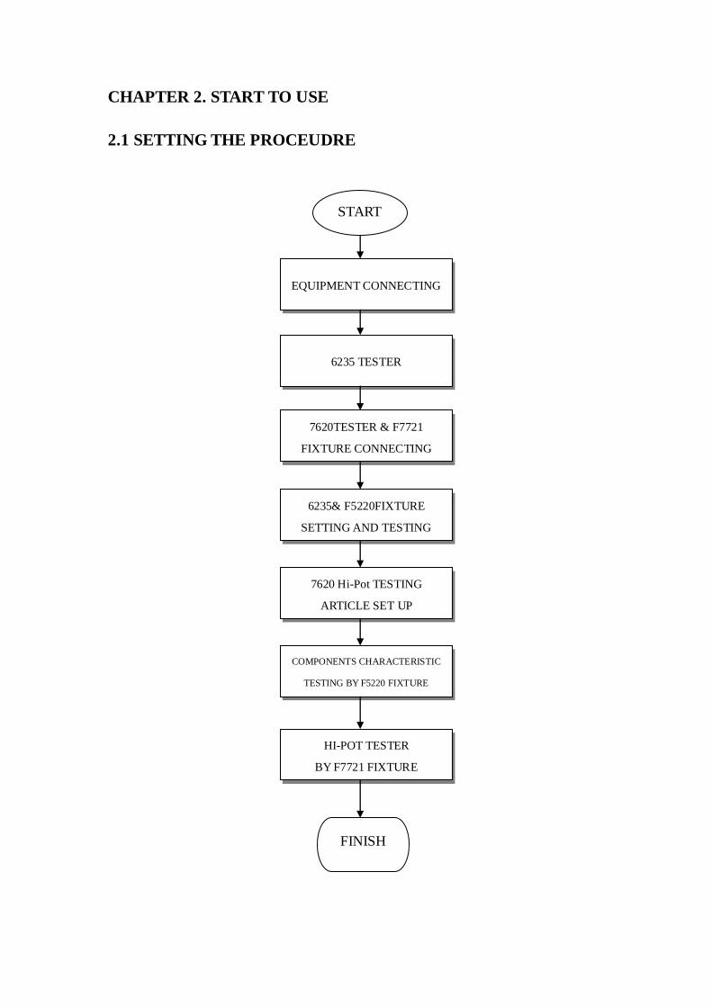
CHAPTER 2. START TO USE
2.1 SETTING THE PROCEUDRE
START
EQUIPMENT CONNECTING
7620TESTER & F7721
FIXTURE CONNECTING
6235& F5220FIXTURE
SETTING AND TESTING
6235 TESTER
7620 Hi-Pot TESTING
ARTICLE SET UP
COMPONENTS CHARACTERISTIC
TESTING BY F5220 FIXTURE
HI-POT TESTER
BY F7721 FIXTURE
FINISH
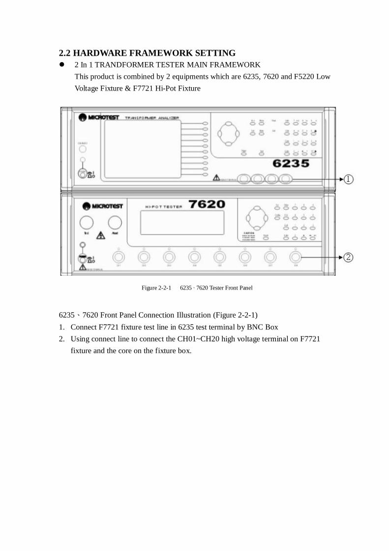
2.2 HARDWARE FRAMEWORK SETTING
2 In 1 TRANDFORMER TESTER MAIN FRAMEWORK
This product is combined by 2 equipments which are 6235, 7620 and F5220 Low
Voltage Fixture & F7721 Hi-Pot Fixture
Figure 2-2-1 6235、7620 Tester Front Panel
6235、7620 Front Panel Connection Illustration (Figure 2-2-1)
1. Connect F7721 fixture test line in 6235 test terminal by BNC Box
2. Using connect line to connect the CH01~CH20 high voltage terminal on F7721
fixture and the core on the fixture box.
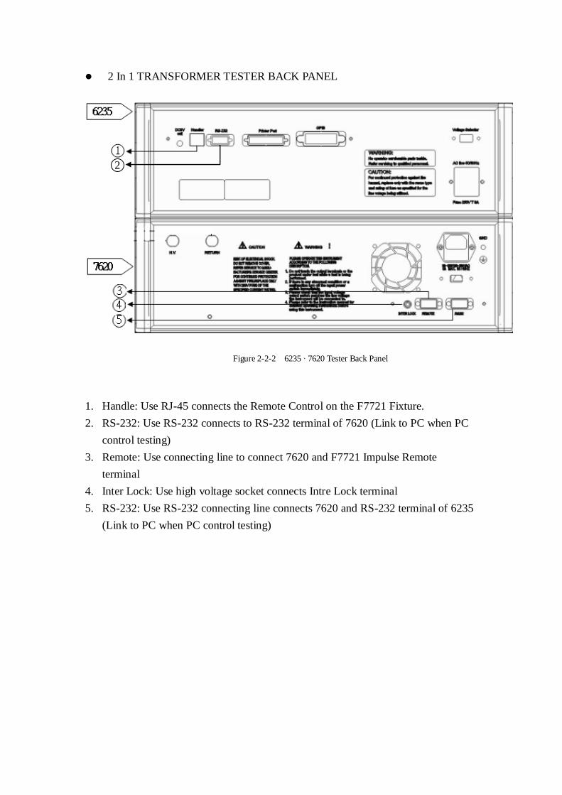
2 In 1 TRANSFORMER TESTER BACK PANEL
Figure 2-2-2 6235、7620 Tester Back Panel
1. Handle: Use RJ-45 connects the Remote Control on the F7721 Fixture.
2. RS-232: Use RS-232 connects to RS-232 terminal of 7620 (Link to PC when PC
control testing)
3. Remote: Use connecting line to connect 7620 and F7721 Impulse Remote
terminal
4. Inter Lock: Use high voltage socket connects Intre Lock terminal
5. RS-232: Use RS-232 connecting line connects 7620 and RS-232 terminal of 6235
(Link to PC when PC control testing)
2 2
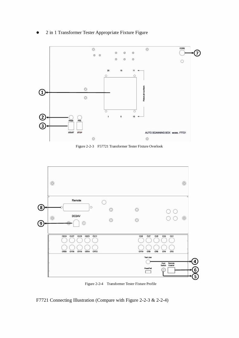
2 in 1 Transformer Tester Appropriate Fixture Figure
Figure 2-2-3 F57721 Transformer Tester Fixture Overlook
Figure 2-2-4 Transformer Tester Fixture Profile
F7721 Connecting Illustration (Compare with Figure 2-2-3 & 2-2-4)
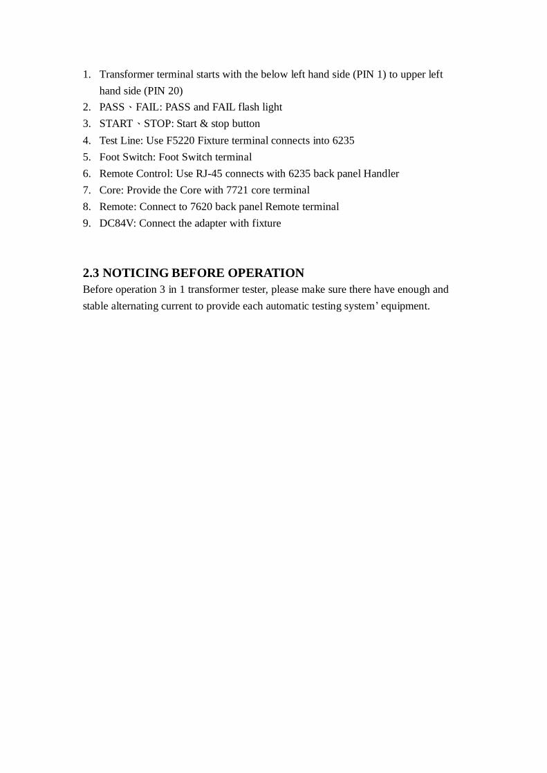
1. Transformer terminal starts with the below left hand side (PIN 1) to upper left
hand side (PIN 20)
2. PASS、FAIL: PASS and FAIL flash light
3. START、STOP: Start & stop button
4. Test Line: Use F5220 Fixture terminal connects into 6235
5. Foot Switch: Foot Switch terminal
6. Remote Control: Use RJ-45 connects with 6235 back panel Handler
7. Core: Provide the Core with 7721 core terminal
8. Remote: Connect to 7620 back panel Remote terminal
9. DC84V: Connect the adapter with fixture
2.3 NOTICING BEFORE OPERATION
Before operation 3 in 1 transformer tester, please make sure there have enough and
stable alternating current to provide each automatic testing system‟ equipment.
CHAPTER 3. OPERATION
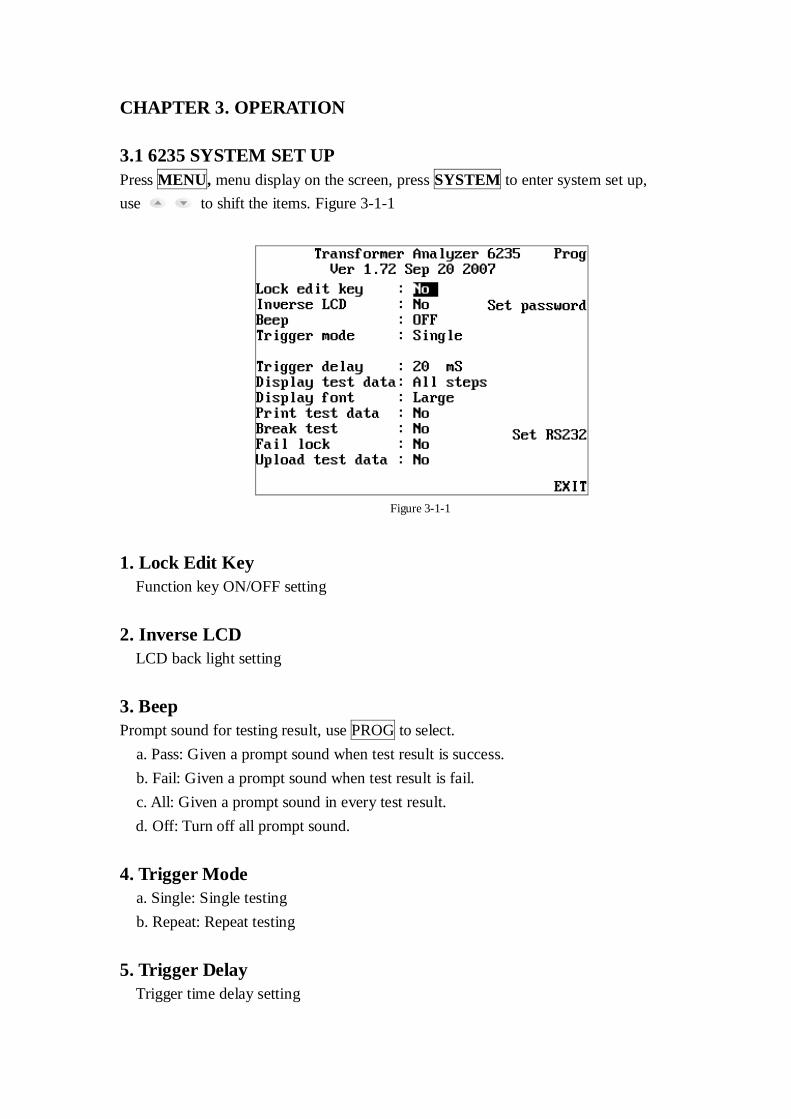
3.1 6235 SYSTEM SET UP
Press MENU, menu display on the screen, press SYSTEM to enter system set up,
use to shift the items. Figure 3-1-1
Figure 3-1-1
1. Lock Edit Key
Function key ON/OFF setting
2. Inverse LCD
LCD back light setting
3. Beep
Prompt sound for testing result, use PROG to select.
a. Pass: Given a prompt sound when test result is success.
b. Fail: Given a prompt sound when test result is fail.
c. All: Given a prompt sound in every test result.
d. Off: Turn off all prompt sound.
4. Trigger Mode
a. Single: Single testing
b. Repeat: Repeat testing
5. Trigger Delay
Trigger time delay setting
6. Display Test Date
a. All Steps: Display all testing information.
b. Fail Steps: Display only failure information
7. Display Font
Character size setting
8. Print Test Data
Printed automatically for test result, or press the PRINT key for printing.
9. Break Test
Choose On 1 NG、On 3 NG & On 5 NG will stop testing while meeting failure on
1、3、5 times. If choose No, than it will not stop the testing.
10. Fail Lock
Fixture will not automatically withdraw only press the STOP key, it reminds that
the testing items is defective products.
11. Upload Test Data
Set-up RS-232 in order to make the test result transferred to computer through
RS-232.
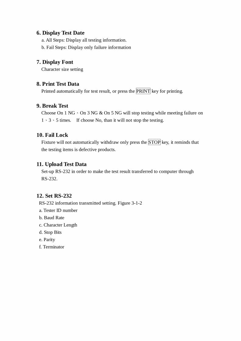
12. Set RS-232
RS-232 information transmitted setting. Figure 3-1-2
a. Tester ID number
b. Baud Rate
c. Character Length
d. Stop Bits
e. Parity
f. Terminator
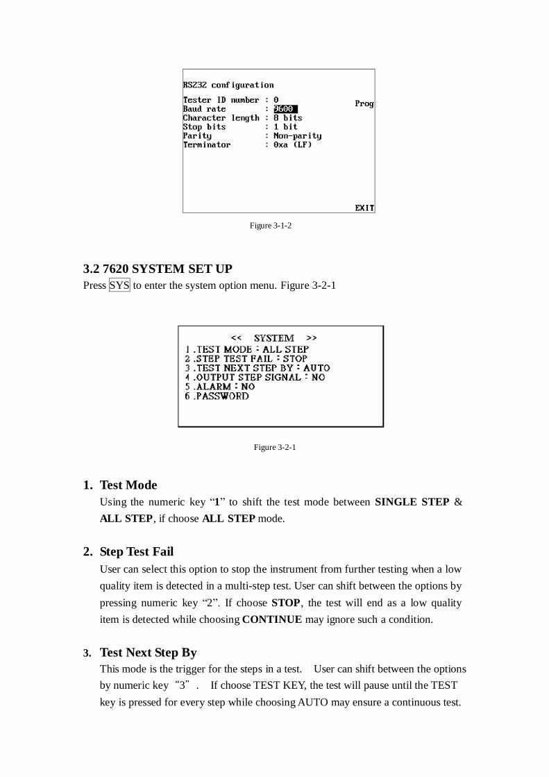
Figure 3-1-2
3.2 7620 SYSTEM SET UP
Press SYS to enter the system option menu. Figure 3-2-1
Figure 3-2-1
1. Test Mode
Using the numeric key “1” to shift the test mode between SINGLE STEP &
ALL STEP, if choose ALL STEP mode.
2. Step Test Fail
User can select this option to stop the instrument from further testing when a low
quality item is detected in a multi-step test. User can shift between the options by
pressing numeric key “2”. If choose STOP, the test will end as a low quality
item is detected while choosing CONTINUE may ignore such a condition.
3. Test Next Step By
This mode is the trigger for the steps in a test. User can shift between the options
by numeric key“3”. If choose TEST KEY, the test will pause until the TEST
key is pressed for every step while choosing AUTO may ensure a continuous test.
4. Output Step Signal
User can use this option to set the signals for every step in a multi-step test. User
can shift between the options by numeric key“4”. If choose YES, the tester
will display the signal results for every step while choosing NO the tester may
display the judgment at the end of the test (in this condition, the judgment will be
FAIL even there is only one low quality item.)
5. Alarm
It is the switch for FAIL alarm. User can shift between the options by numeric
key“5”. If choose ON, the FAIL signal lamp will bright with a beep while
choosing OFF the signal lamp will bright without a beep.
6. Password
Change password. Input the original password first, then input the new password
and confirm it. (The original password for the system is 7620)
7. Ramp Time
Ramp time setting, in order to make fixture have enough time to work.
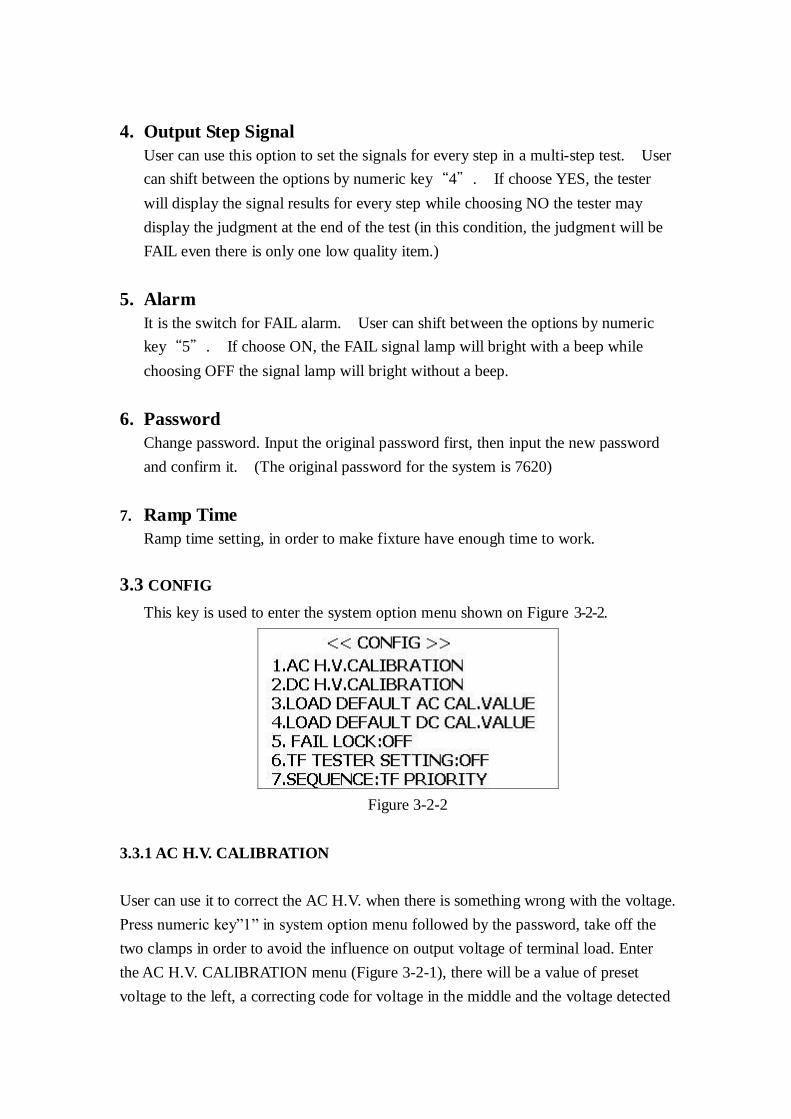
3.3 CONFIG
This key is used to enter the system option menu shown on Figure 3-2-2.
Figure 3-2-2
3.3.1 AC H.V. CALIBRATION
User can use it to correct the AC H.V. when there is something wrong with the voltage.
Press numeric key”1” in system option menu followed by the password, take off the
two clamps in order to avoid the influence on output voltage of terminal load. Enter
the AC H.V. CALIBRATION menu (Figure 3-2-1), there will be a value of preset
voltage to the left, a correcting code for voltage in the middle and the voltage detected
to the right. At the beginning, the cursor will be on the line marked 500V and detect
the voltage of it. Use up arrow and down arrow to adjust the detected voltage to the
preset voltage by change the correcting code. The higher the correcting code is, the
higher the output voltage will be. Press ENTER to shift to the next line, correct the
AC H.V. in the same way. If you press ENTER while the cursor is on the line marked
2500V, the cursor will back to the line marked 500V. You can turn to the next page to
continue the work by press the right button. When the work is finished, press EXIT to
exit, the values will be saved automatically.
3.3.2 DC H.V. CALIBRATION
User can use it to correct the DC H.V. when there is something wrong with the
voltage. The method is the same as the AC H.V. correcting. Notice that the maximum
voltage for DC is 6000V and there will be two more line than the AC H.V. correcting.
3.3.3 LOAD DEFAULT AC CAL. VALUE&LOAD DEFAULT DC CAL. VALUE
User can load Default AC/DC Cal. Values by press S3/S4 followed by the password in
the system option menu. The system will warn user with a message that “Current
correcting code will be lost”. Press ENTER to load the default values or press EXIT
to abort.
3.3.4 FAIL LOCK
When the function is ON, the clips of fixture head will grip the fail sample for
noticing staff the sample is defective product.
3.3.5 TF TESTER SETING
When the function is ON, fixture will switch to Transformer Test mode (low
frequency) then you could use transformer tester (6237) to test your sample, 6237 will
learn the standard value of sample. If leave the test window or turn off this function,
fixture will switch to stand by status.
3.3.6 SEQUENCE
Using this function to adjust the test sequence, there are TF PRIORITY、HV
PRIORITY、ONLY TF and ONLY HV four modes. If choose TF PRIORITY mode,
system will first start Transformer Test mode then Hi-Pot Test mode for measurement.
If choose HV PRIORITY mode, system will first start Hi-Pot Test mode then
Transformer Test mode for measurement. If choose ONLY TF mode, system will only
start Transformer Test mode for measurement. If choose ONLY HV mode, system will
only start Hi-Pot Test mode for measurement.
3.4 6235 TESTING ITEM SET UP
After set up all of the machines, you can start to edit the testing article, pls. find
below for system set up
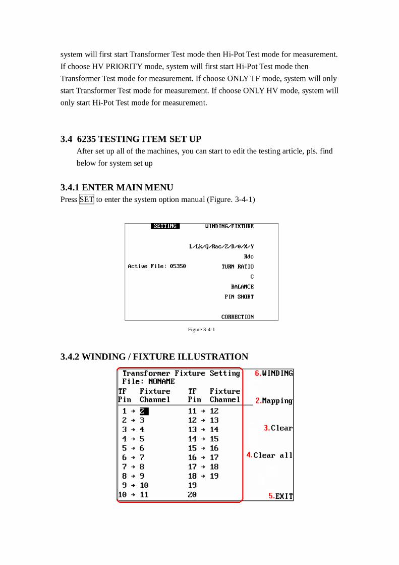
3.4.1 ENTER MAIN MENU
Press SET to enter the system option manual (Figure. 3-4-1)
Figure 3-4-1
3.4.2 WINDING / FIXTURE ILLUSTRATION
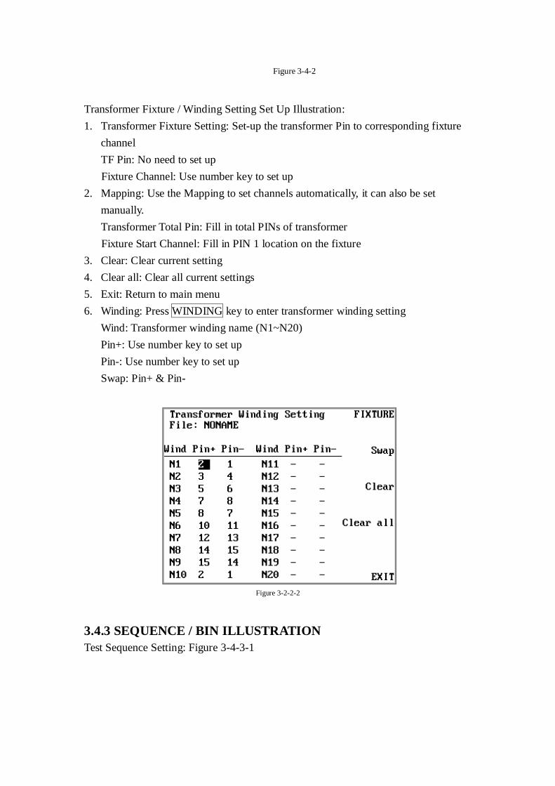
Figure 3-4-2
Transformer Fixture / Winding Setting Set Up Illustration:
1. Transformer Fixture Setting: Set-up the transformer Pin to corresponding fixture
channel
TF Pin: No need to set up
Fixture Channel: Use number key to set up
2. Mapping: Use the Mapping to set channels automatically, it can also be set
manually.
Transformer Total Pin: Fill in total PINs of transformer
Fixture Start Channel: Fill in PIN 1 location on the fixture
3. Clear: Clear current setting
4. Clear all: Clear all current settings
5. Exit: Return to main menu
6. Winding: Press WINDING key to enter transformer winding setting
Wind: Transformer winding name (N1~N20)
Pin+: Use number key to set up
Pin-: Use number key to set up
Swap: Pin+ & Pin-
Figure 3-2-2-2
3.4.3 SEQUENCE / BIN ILLUSTRATION
Test Sequence Setting: Figure 3-4-3-1
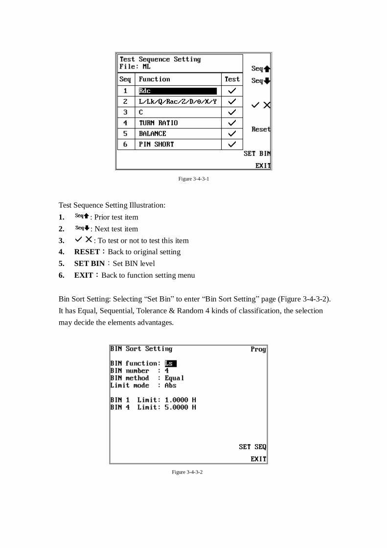
Figure 3-4-3-1
Test Sequence Setting Illustration:
1. : Prior test item
2. : Next test item
3. : To test or not to test this item
4. RESET:Back to original setting
5. SET BIN:Set BIN level
6. EXIT:Back to function setting menu
Bin Sort Setting: Selecting “Set Bin” to enter “Bin Sort Setting” page (Figure 3-4-3-2).
It has Equal, Sequential, Tolerance & Random 4 kinds of classification, the selection
may decide the elements advantages.
Figure 3-4-3-2
BIN Sort Setting Illustration:
1. BIN Function: BIN classification setting, includes Ls、Lk、Q、Rsand Rdc. If not
used any classify functions, please turn the OFF button to close the function.
2. BIN Number: BIN range setting. Based on the difference setting on Bin method,
classification limited is difference, Equal can be classified into 32 levels,
Sequential、tolerance and random can be divided into 15 levels.
3. BIN Method: Classification set up, including Equal, Sequential, Tolerance and
Random
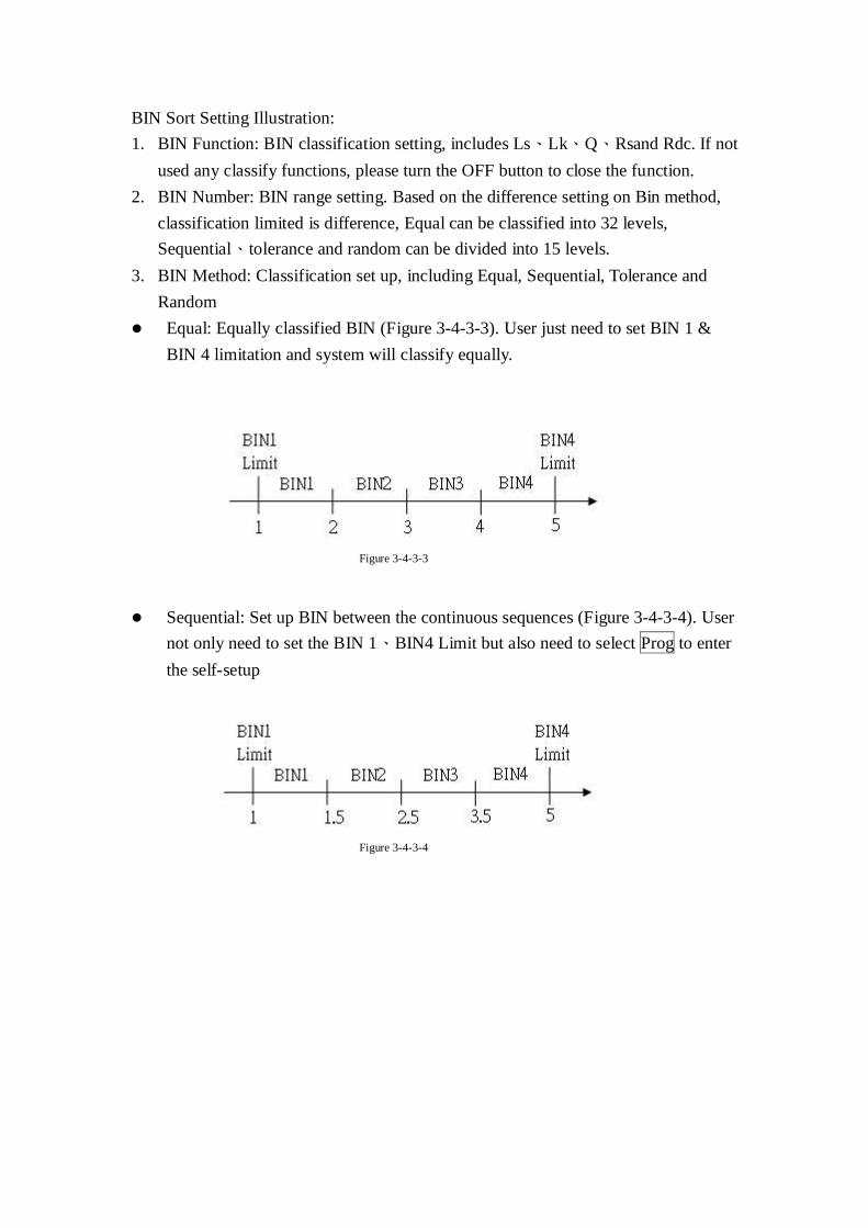
Equal: Equally classified BIN (Figure 3-4-3-3). User just need to set BIN 1 &
BIN 4 limitation and system will classify equally.
Figure 3-4-3-3
Sequential: Set up BIN between the continuous sequences (Figure 3-4-3-4). User
not only need to set the BIN 1、BIN4 Limit but also need to select Prog to enter
the self-setup
Figure 3-4-3-4
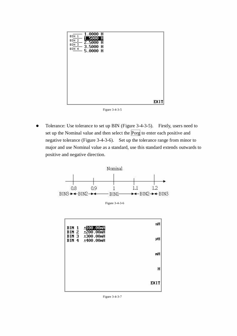
Figure 3-4-3-5
Tolerance: Use tolerance to set up BIN (Figure 3-4-3-5). Firstly, users need to
set up the Nominal value and then select the Porg to enter each positive and
negative tolerance (Figure 3-4-3-6). Set up the tolerance range from minor to
major and use Nominal value as a standard, use this standard extends outwards to
positive and negative direction.
Figure 3-4-3-6
Figure 3-4-3-7
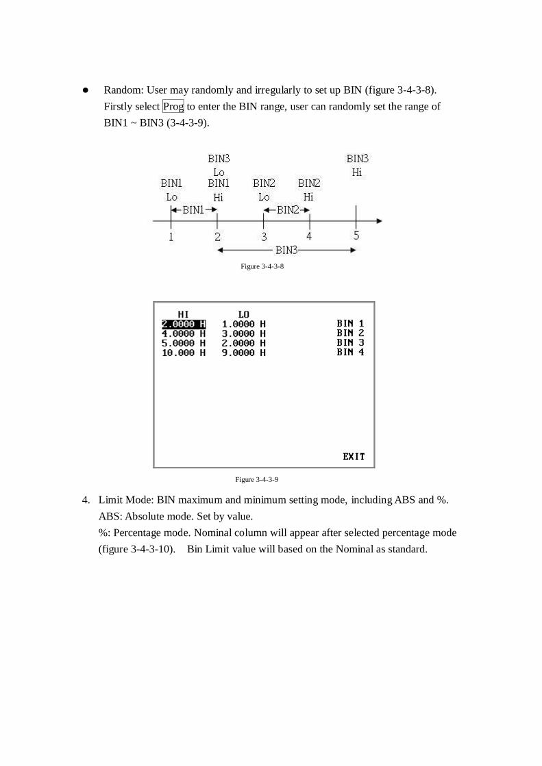
Random: User may randomly and irregularly to set up BIN (figure 3-4-3-8).
Firstly select Prog to enter the BIN range, user can randomly set the range of
BIN1 ~ BIN3 (3-4-3-9).
Figure 3-4-3-8
Figure 3-4-3-9
4. Limit Mode: BIN maximum and minimum setting mode, including ABS and %.
ABS: Absolute mode. Set by value.
%: Percentage mode. Nominal column will appear after selected percentage mode
(figure 3-4-3-10). Bin Limit value will based on the Nominal as standard.
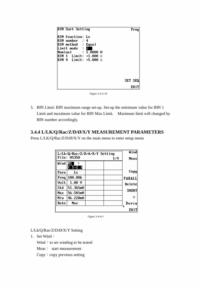
Figure 3-4-3-10
5. BIN Limit: BIN maximum range set-up. Set-up the minimum value for BIN 1
Limit and maximum value for BIN Max Limit. Maximum limit will changed by
BIN number accordingly.
3.4.4 L/LK/Q/Rac/Z/D/Ø /X/Y MEASUREMENT PARAMETERS
Press L/LK/Q/Rac/Z/D/Ø /X/Y on the main menu to enter setup menu
Figure 3-4-4-1
L/Lk/Q/Rac/Z/D/Ø /X/Y Setting
1. Set Wind:
Wind:to set winding to be tested
Meas: start measurement
Copy:copy previous setting
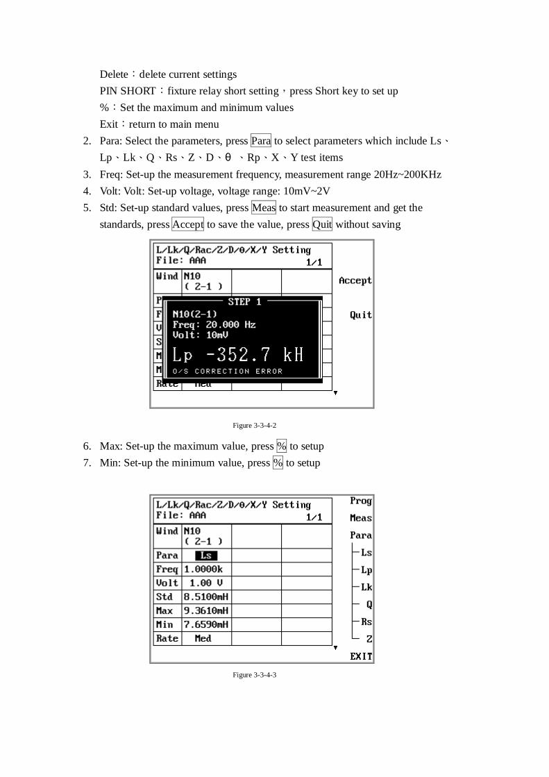
Delete:delete current settings
PIN SHORT:fixture relay short setting,press Short key to set up
%:Set the maximum and minimum values
Exit:return to main menu
2. Para: Select the parameters, press Para to select parameters which include Ls、
Lp、Lk、Q、Rs、Z、D、θ 、Rp、X、Y test items
3. Freq: Set-up the measurement frequency, measurement range 20Hz~200KHz
4. Volt: Volt: Set-up voltage, voltage range: 10mV~2V
5. Std: Set-up standard values, press Meas to start measurement and get the
standards, press Accept to save the value, press Quit without saving
Figure 3-3-4-2
6. Max: Set-up the maximum value, press % to setup
7. Min: Set-up the minimum value, press % to setup
Figure 3-3-4-3
8. Rate: Set-up the speed rate, use Prog to adjust
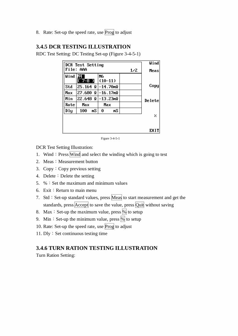
3.4.5 DCR TESTING ILLUSTRATION
RDC Test Setting: DC Testing Set-up (Figure 3-4-5-1)
Figure 3-4-5-1
DCR Test Setting Illustration:
1. Wind:Press Wind and select the winding which is going to test
2. Meas:Measurement button
3. Copy:Copy previous setting
4. Delete:Delete the setting
5. %:Set the maximum and minimum values
6. Exit:Return to main menu
7. Std:Set-up standard values, press Meas to start measurement and get the
standards, press Accept to save the value, press Quit without saving
8. Max:Set-up the maximum value, press % to setup
9. Min:Set-up the minimum value, press % to setup
10. Rate: Set-up the speed rate, use Prog to adjust
11. Dly:Set continuous testing time
3.4.6 TURN RATION TESTING ILLUSTRATION
Turn Ration Setting:
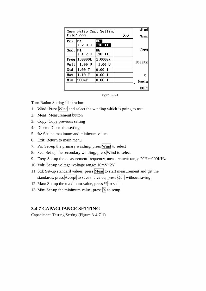
Figure 3-4-6-1
Turn Ration Setting Illustration:
1. Wind: Press Wind and select the winding which is going to test
2. Meas: Measurement button
3. Copy: Copy previous setting
4. Delete: Delete the setting
5. %: Set the maximum and minimum values
6. Exit: Return to main menu
7. Pri: Set-up the primary winding, press Wind to select
8. Sec: Set-up the secondary winding, press Wind to select
9. Freq: Set-up the measurement frequency, measurement range 20Hz~200KHz
10. Volt: Set-up voltage, voltage range: 10mV~2V
11. Std: Set-up standard values, press Meas to start measurement and get the
standards, press Accept to save the value, press Quit without saving
12. Max: Set-up the maximum value, press % to setup
13. Min: Set-up the minimum value, press % to setup
3.4.7 CAPACITANCE SETTING
Capacitance Testing Setting (Figure 3-4-7-1)
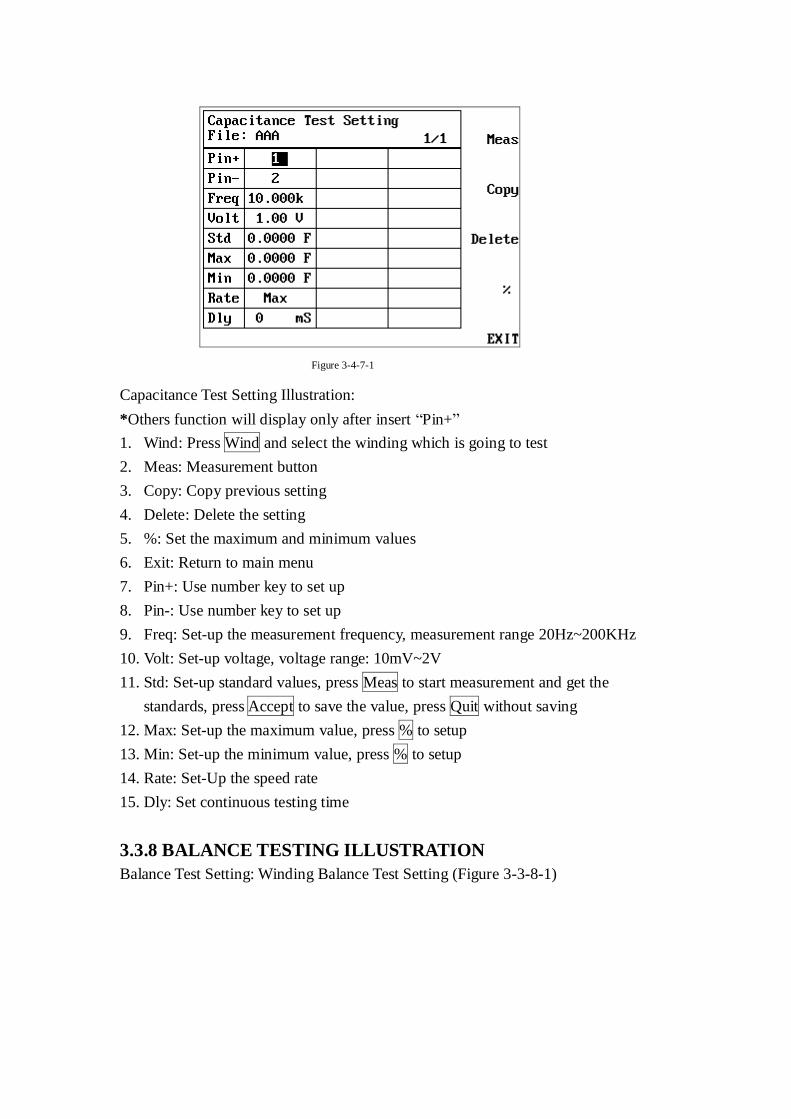
Figure 3-4-7-1
Capacitance Test Setting Illustration:
*Others function will display only after insert “Pin+”
1. Wind: Press Wind and select the winding which is going to test
2. Meas: Measurement button
3. Copy: Copy previous setting
4. Delete: Delete the setting
5. %: Set the maximum and minimum values
6. Exit: Return to main menu
7. Pin+: Use number key to set up
8. Pin-: Use number key to set up
9. Freq: Set-up the measurement frequency, measurement range 20Hz~200KHz
10. Volt: Set-up voltage, voltage range: 10mV~2V
11. Std: Set-up standard values, press Meas to start measurement and get the
standards, press Accept to save the value, press Quit without saving
12. Max: Set-up the maximum value, press % to setup
13. Min: Set-up the minimum value, press % to setup
14. Rate: Set-Up the speed rate
15. Dly: Set continuous testing time
3.3.8 BALANCE TESTING ILLUSTRATION
Balance Test Setting: Winding Balance Test Setting (Figure 3-3-8-1)
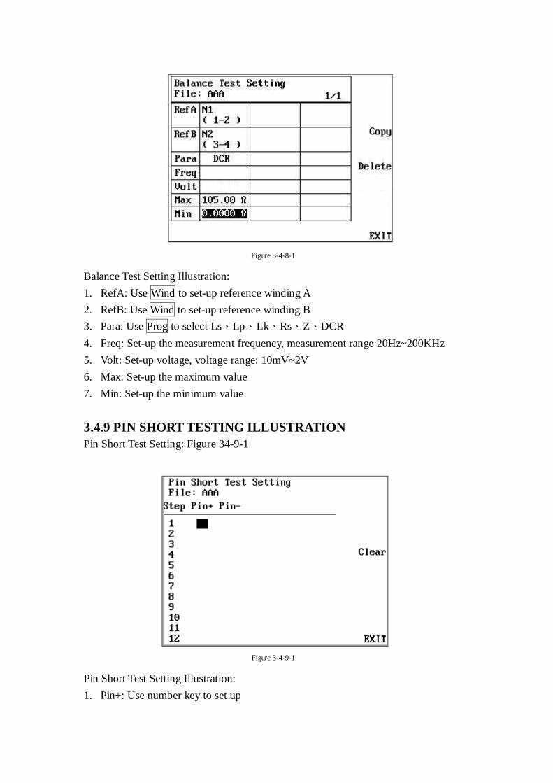
Figure 3-4-8-1
Balance Test Setting Illustration:
1. RefA: Use Wind to set-up reference winding A
2. RefB: Use Wind to set-up reference winding B
3. Para: Use Prog to select Ls、Lp、Lk、Rs、Z、DCR
4. Freq: Set-up the measurement frequency, measurement range 20Hz~200KHz
5. Volt: Set-up voltage, voltage range: 10mV~2V
6. Max: Set-up the maximum value
7. Min: Set-up the minimum value
3.4.9 PIN SHORT TESTING ILLUSTRATION
Pin Short Test Setting: Figure 34-9-1
Figure 3-4-9-1
Pin Short Test Setting Illustration:
1. Pin+: Use number key to set up
2. Pin-: Use number key to set up
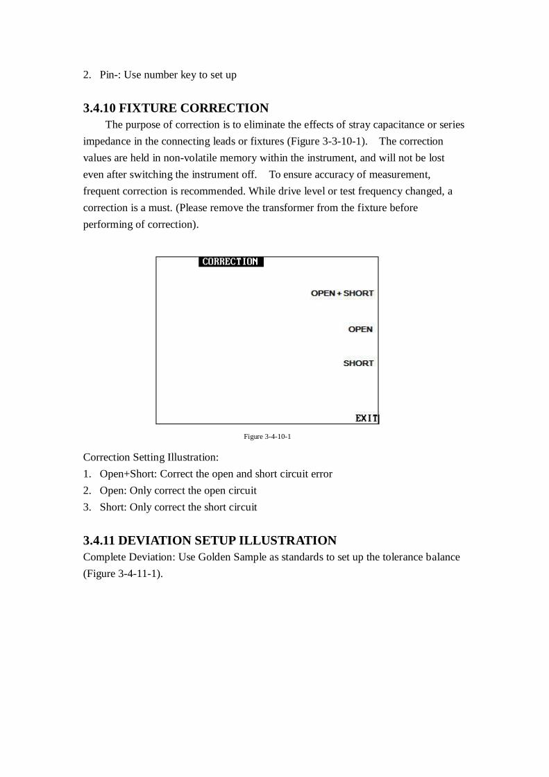
3.4.10 FIXTURE CORRECTION
The purpose of correction is to eliminate the effects of stray capacitance or series
impedance in the connecting leads or fixtures (Figure 3-3-10-1). The correction
values are held in non-volatile memory within the instrument, and will not be lost
even after switching the instrument off. To ensure accuracy of measurement,
frequent correction is recommended. While drive level or test frequency changed, a
correction is a must. (Please remove the transformer from the fixture before
performing of correction).
Figure 3-4-10-1
Correction Setting Illustration:
1. Open+Short: Correct the open and short circuit error
2. Open: Only correct the open circuit
3. Short: Only correct the short circuit
3.4.11 DEVIATION SETUP ILLUSTRATION
Complete Deviation: Use Golden Sample as standards to set up the tolerance balance
(Figure 3-4-11-1).
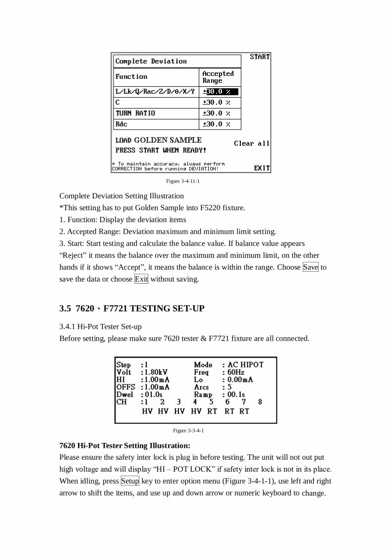
Figure 3-4-11-1
Complete Deviation Setting Illustration
*This setting has to put Golden Sample into F5220 fixture.
1. Function: Display the deviation items
2. Accepted Range: Deviation maximum and minimum limit setting.
3. Start: Start testing and calculate the balance value. If balance value appears
“Reject” it means the balance over the maximum and minimum limit, on the other
hands if it shows “Accept”, it means the balance is within the range. Choose Save to
save the data or choose Exit without saving.
3.5 7620、F7721 TESTING SET-UP
3.4.1 Hi-Pot Tester Set-up
Before setting, please make sure 7620 tester & F7721 fixture are all connected.
Figure 3-3-4-1
7620 Hi-Pot Tester Setting Illustration:
Please ensure the safety inter lock is plug in before testing. The unit will not out put
high voltage and will display “HI – POT LOCK” if safety inter lock is not in its place.
When idling, press Setup key to enter option menu (Figure 3-4-1-1), use left and right
arrow to shift the items, and use up and down arrow or numeric keyboard to change.
Step: Display current step, use up and down arrow or numeric keyboard to audit.
Mode: Use up arrow and down arrow to shift the modes between AC、DC、IR &
LS. LS mode is different form other three, it has to
LS Set-up step:
1. When choosing LS mode, the screen will appear [Press Test button, when setup
is complete.] Please set up out put and 回授 channel.
2. Press 7620 TEST button on the left hand side, the Hi-Pot out put and 回授
will flash up the green and red light. Please make sure the output is connected
by high voltage line with F7620 fixture, also the testing item is already put in
the fixture
3. After checked, please press Learn button on 7700 to make 7700 enter the
waveform learning appearance
4. Choose Learn function on the 7700 screen, 7700 will learn the last testing
waveform information automatically
5. Finished LS mode setting, please set up other testing item for 7620 directly
Volt: Use up and down arrow to edit output voltage setting or key in the voltage
value by numeric keypad (If the value you keyed in beyond the upper limit or
below the lower limit, it will automatically fit the limit).
Freq: Use up and down arrow to shift the AC frequency between 50Hz & 60Hz.
HI: There will be a message showing HILIMIT as the FAIL indicator indicates
when the current detected is beyond the upper limit.
LO: There will be a message showing LOLIMIT as the FAIL indicator indicates
when the current detected is beyond the lower limit. If the voltage is rising, the
check for lower limit will pause until the process of rising finish.
OFFS: There are two ways for offset calibration: Auto setting & Manual setting.
Auto setting: Put the cursor at “OFF” and press “TEST”, then the tester will te st
the voltage and display the result, also a string of “SAVE=ENTER” shows up,
press “ENTER” to save the result or press “EXIT” to abort. If the result saved,
every time the test is running, the certain value would be taken out to make the
test more accurate.
ARCS: The way to set Arc Sensitivity is the same as the one for other settings.
The higher the value is, the more sensitive it will be for the tester to arcs. And it
will be ignored if the value sets at 0.
DWEL: The value here determines the lasting time of test. If the value equals
00.0, there will be a continuous test.
RAMP: The time needed for voltage to rise to preset voltage from 0.
CH: High voltage output setting. CH1~8 correspond 7620 front panel high
voltage out setting. Please define HV & RT below CH1~8, if not using the
channel the set up is unneeded.
3.6 PROGRAM AND STATISTIC INFORMATION SAVING
MANAGEMENT
Based on the different tester and different testing article, the information will be
saved in 6235、7620 separately yet.
6235 testing information save route: Press the Menu button on the front panel
and select STSTISTICS function key to enter the testing information statistic
screen.
7620 testing information save route: Press the Stat button on the front panel to
enter the testing information statistic screen.
Recommended