112/04/18 1
Fault Management in IP-Over-WDM Networks:
WDM Protection Versus IP Restoration
Adviser: Ho-Ting Wu Presenter: Ze-Yang Guo

112/04/18 2
Outline
• Introduction– Fault-Management Techniques– Illustrative Example– Integer Linear Program (ILPs)
• An upper bound for the guaranteed network capacity
• Heuristic Algorithm• Recovery Time Analysis
– WDM Shared-Path Protection– IP Restoration
• Illustrative Numerical Results• Conclusions• References

112/04/18 3
Introduction
• Wavelength-Division Multiplexing– Divide tremendous bandwidth of a fiber (up
to 50 Tbits/s)
– Each WDM channel may be operated at whatever speed one desires.
– Transmissions on different wavelengths are coupled into a single fiber.
– An optical crossconnect (OXC) can switch the optical signal on a WDM channel from an input port to an output port.
112/04/18 4
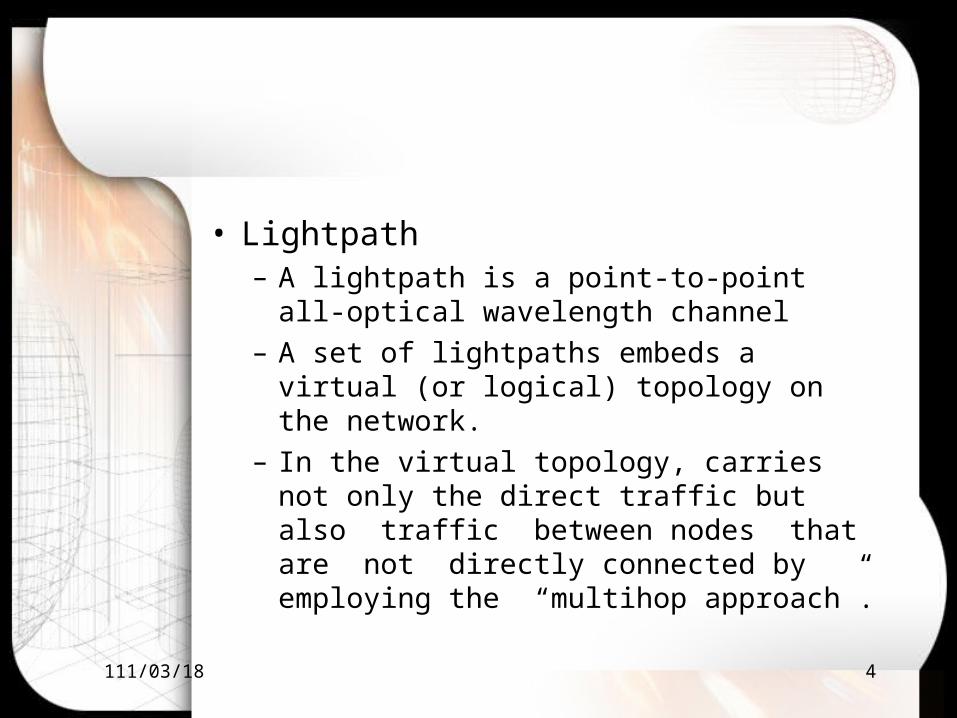
• Lightpath– A lightpath is a point-to-point all-optical
wavelength channel
– A set of lightpaths embeds a virtual (or logical) topology on the network.
– In the virtual topology, carries not only the direct traffic but also traffic between nodes that are not directly connected by employing the “multihop approach”.

112/04/18 5

112/04/18 6
• We model the variation in network traffic by multiplying the traffic matrix by a scalar, called the “load factor,” which we denote by α.
• We are given an IP-over-WDM network and a traffic matrix, we are required to find a virtual topology and the corresponding traffic flow assignment that will– provide protection against a single fiber failure.– maximize α.

112/04/18 7
• Fault-Management Techniques– Protection
Spare capacity is reserved during call setup.
– Restoration
Spare capacity available after the
fault’s occurrence is utilized for rerouting the disrupted traffic.

112/04/18 8
• Fault-Management Techniques in IP-Over-WDM– Provide protection at the WDM layer
Set up a backup lightpath for every primary lightpath in the network.
– Provide restoration at IP layerOverprovision the network after a fiber failure, the network should still be able to carry all the traffic it was carrying before the fiber failure.

112/04/18 9
• WDM Protection– Dedicated-path protection:
At the time of call setup, for each primary path, a fiber-disjoint backup path and wavelength are reserved and dedicated to that call.
The backup wavelength reserved on the links of the backup path are dedicated to that call and are not shared with other backup paths.
112/04/18 10
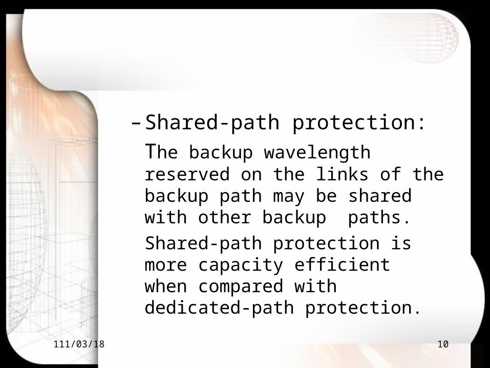
– Shared-path protection:
The backup wavelength reserved on the links of the backup path may be shared with other backup paths.
Shared-path protection is more capacity efficient when compared with dedicated-path protection.

112/04/18 11
• IP Restoration:
Routers within an AS exchange routing information by employing an interior gateway protocol (IGP).
By using an IGP, an AS can combat a link failure.

112/04/18 12
• Illustrative Example– WDM shared-path protection solution– IP-restoration solution

112/04/18 13
• WDM shared-path protection solutionThe primary lightpaths are (4, 5, 6)
and(5, 10, 9), on the same wavelength,
the backup lightpaths are (4, 8, 0, 6) and
(5,4, 8, 7, 9), on the same wavelength .

112/04/18 14
• IP-restoration solution
The solution consists of two lightpaths between node 4 and node 6 along the routes (4, 5, 6) and (4, 8, 0, 6) on different wavelengths, respectively.

112/04/18 15
• Integer Linear Program(CPLEX)– The solution to the ILP formulation
provides us with an optimal virtual topology and a traffic flow assignment that maximizes the guaranteed network
capacity.– Since the complete ILP formulations were
taking a very long time to solve, weexperimented by splitting the ILPformulations into two parts.

112/04/18 16
An upper bound for the guaranteed network capacity
• Capacity– Given: topology G, traffic matrix Λ,C be a
cutset that partitions the topology G into two components whose node sets are V1 and V2, is equal to the traffic from node u to node v, define a congestion with a single link failure as
CτCτCτ
uvΛ

112/04/18 17
• Let be the maxixum value of
taken over all possible cutset, if the capacity of a lightpath is equal to B, then the load factor α cannot be greater than hence, an upper bound on α is
*Cτ
Cτ
)τB(
C*
C*1 τ
B=U

112/04/18 18
• If node i has transmitters an receivers , then the maximum amount of traffic that can be sourced or sinked at node i is bounded by . B and . B, respectively.
• The amount of traffic sourced from node i is given by and the amount of traffic sinked at node is given by
Thus
it ir
∑V∈j ijΛ
it ir
∑∈j jiΛV

112/04/18 19
• The following upper bound is used only for the IP restoration technique, let the degree of node i be denoted by deg(i), note that in IP restoration, thus

112/04/18 20
• Based on the above analysis, tighter upper bounds for the load factor for WDM shared-path protection and IP-restoration can be computed as:
)U,Umin(=U 21WDM
)U,Umin(=U 31IP

112/04/18 21
• Heuristic AlgortithmThe heuristic algorithm is based on the concept of a “branch- exchange.” The algorithm starts by constructing an initial virtual topology and iterates between the following two phases. In the first phase, the heuristic attempts to tear down as many lightpaths as possible , without increasing the load on the maximally loaded link,and the least loaded lightpath is removed first.In the second phase, the heuristic attempts to decrease the load of the maximally loaded link by setting up as many lightpaths as possible by employing the resources freed up in the first phase. The heuristic iterates between these two phases until either it finds a stable virtual topology

112/04/18 22
– WDM protection

112/04/18 23

112/04/18 24
– IP resoration
differences with WDM heuristic:
Only needs to set up the primary lightpath.

112/04/18 25

112/04/18 26

112/04/18 27
• Recovery Time Analysis– WDM shared-path protection
1)The fiber failure is detected by the network nodes adjacent to the fiber, we assume that the time to detect a fiber failure is F, that F = 100μs.
2) Message processing time at a node is denoted by D, that D = 100μs.
3) Propagation delay on each fiber is denoted by P, we assume that the fiber length is equal to 80 km, which corresponds to a delay of 400μs.
4) The time to configure and test a cross-connect is C, we use C = 5ms in our calculations.

112/04/18 28
5) The number of hops from the node adjacent to the failed fiber to the source node of the connection is .
6) The number of hops in the backup route from the source node to the destination node is .
The total time for
shared-path protection
is given by
sh
bh

112/04/18 29
– IP restoration
1) The fiber failure is detected by the destination nodes of all the failed lightpaths. Since we assume that the WDM hardware is tightly coupled with the IP layer, hence the time to detect a fiber failure F, that F = 10ms
2) The processing time for link-state update messages is dominated by the time it takes to run the broadcast algorithm, We assume that the IP router has dedicated hardware for running the broadcast algorithm. Thus, we use D = 1ms.
3) The propagation delay on a fiber 400μs.

112/04/18 30
4) The time required to recompute the routing table at a node is R, We use R = 200ms.
5) The number of hops from the failed fiber to the
destination node of the failed lightpath is 6) The number of hops from the destination node of the failed lightpath to the most distant node in the network is n.
The total time for IP
restoration is given by
dh

112/04/18 31
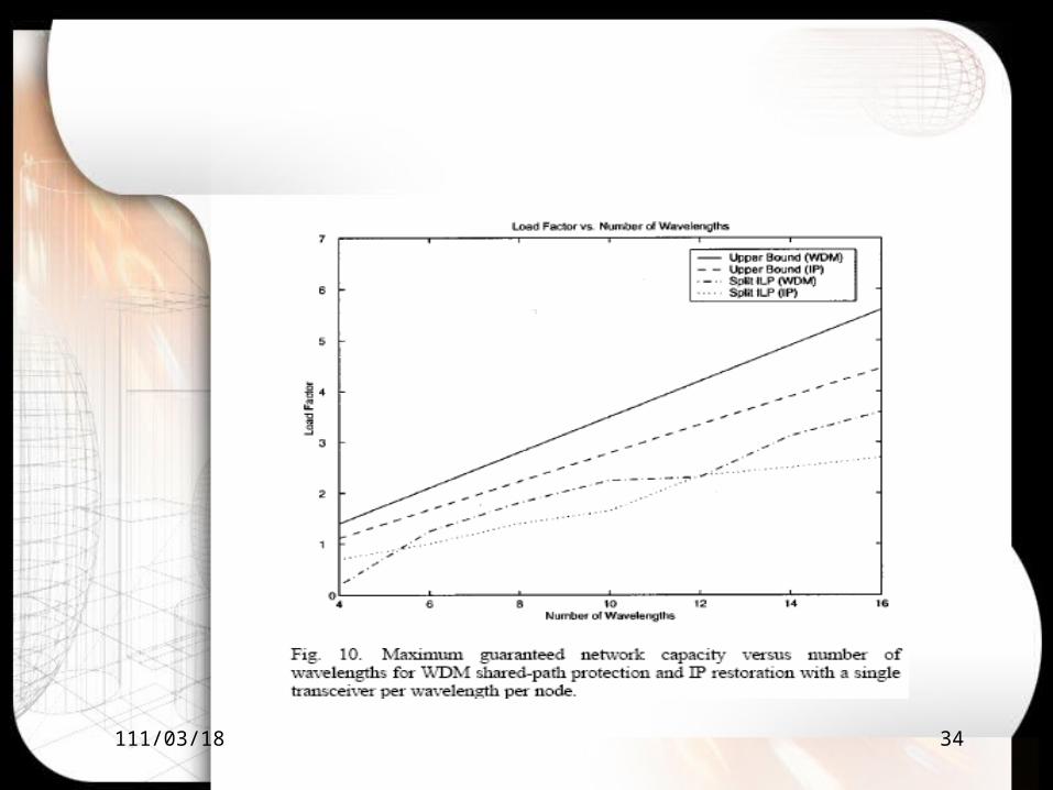
• Illustrative numerical resultsWe assumed a single transmitter and receiver per wavelength per node in the network
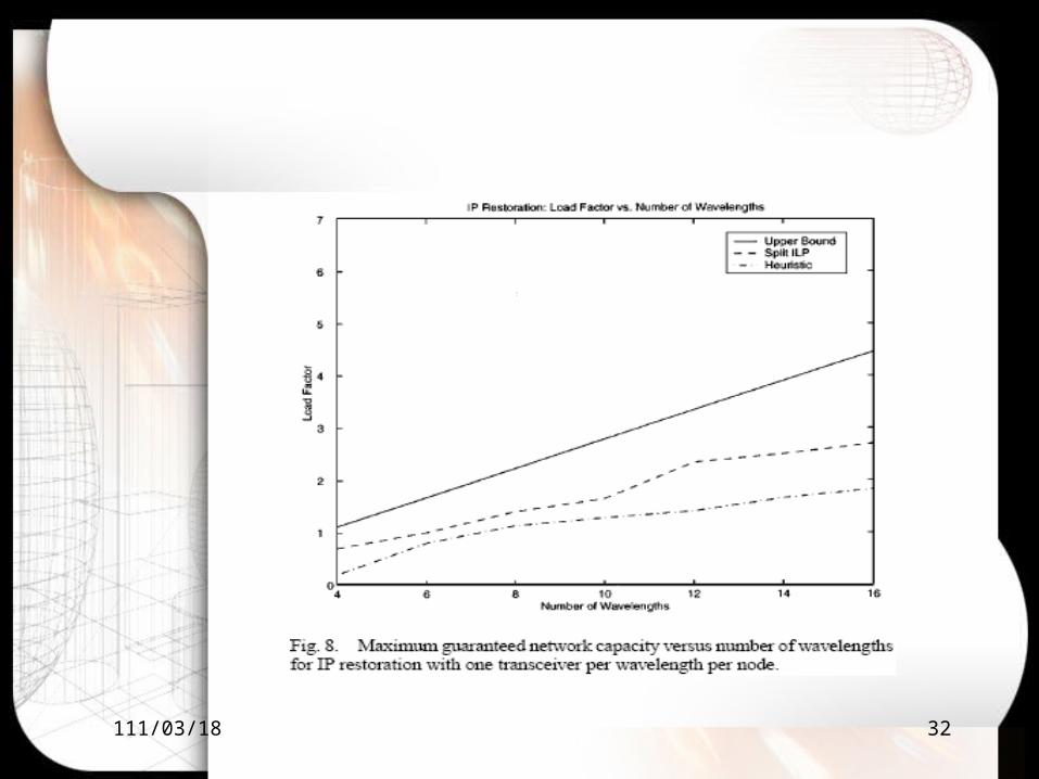
112/04/18 32
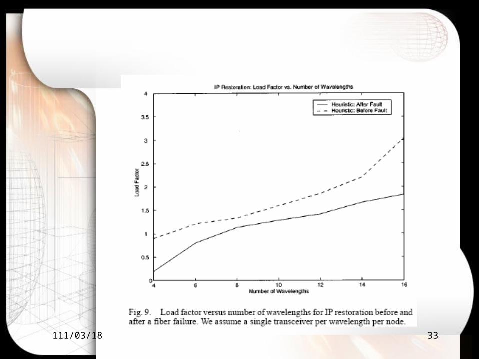
112/04/18 33
112/04/18 34

112/04/18 35
Now, since the upper bound is always less than , and in this particular example, since the upper bound is also less than , the upper bound on α for the IP restoration solution is lower than the upper bound for the WDM solution. On the other hand, if we allow multiple transceivers per wavelength per node, then IP restoration performs slightly better than WDM shared-path protection, as the figure.11
2U3U
3U 1U

112/04/18 36
112/04/18 37
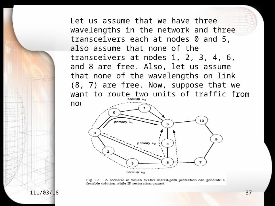
Let us assume that we have three wavelengths in the network and three transceivers each at nodes 0 and 5, also assume that none of the transceivers at nodes 1, 2, 3, 4, 6, and 8 are free. Also, let us assume that none of the wavelengths on link (8, 7) are free. Now, suppose that we want to route two units of traffic from node 0 to node 5.

112/04/18 38
This table shows the average WDM shared-path protection and IP restoration times. We assume that the network has 16 wavelengths and that each node is equipped with multiple transceivers on each wavelength, and maximize the load factor α.
112/04/18 39
Conclusion
• WDM shared-path protection outperformed IP restoration for our example network, possibly due to the limited number of transceivers per node.
• Since the recovery times for WDM shared-path protection and IP restoration. We found that the recovery times for WDM shared-path protection are much faster than the recovery times for IP restoration.
• Under some certain scenario WDM shared-path protection can produce feasible solution, but IP restoration cannot.
• That hard to say that WDM shared-path or IP restoration which one is better.

112/04/18 40
References
• O. Gerstel, “Opportunities for optical protection and restoration,” in Optical Fiber Communication Conf., vol. 2, San Jose, CA, Feb. 1998, pp.269–270.
• S. Ramamurthy and B. Mukherjee, “Survivable WDM mesh networks, Part II—Restoration,” in Proc. IEEE ICC’99, vol. 3, Vancouver, BC,June 1999, pp. 2023–2030.
• W. D. Grover, “The selfhealing network: A fast distributed restoration technique for networks using digital crossconnect machines,” in Proc.IEEE Globecom’87, 1987, pp. 28.2.1–28.2.6.
• Nasir Ghani, Ph.D. “IP over optical” Industry Program Chair, OPTICOMM 2000
• Bala Rajagopalan, Dimitrios Pendarakis, Debanjan Saha, Ramu S. Ramamoorthy,and Krishna Bala, Tellium, Inc.“IP over Optical Networks:Architectural Aspects”
Recommended


![Energy-Saving in IP Over WDM Networks by Putting ......IP over WDM networks achieved by switching off router line cards during low-demand hours. In [24], they also presented a detailed](https://img.pdfslide.net/doc/110x75/5fb93ea846b9283d5246341a/energy-saving-in-ip-over-wdm-networks-by-putting-ip-over-wdm-networks-achieved.jpg)