2033-6
Joint ICTP/IAEA Advanced School on Dosimetry in DiagnosticRadiology and its Clinical Implementation
Renato Padovani
11 - 15 May 2009
EFOMP
Dosimetry for FluoroscopyBasics
IAEAInternational Atomic Energy Agency
Dosimetry for fluoroscopy -basics
Renato PadovaniMedical Physics Department
University Hospital, Udine, Italy
Joint ICTP-IAEA Advanced school on Dosimetry in Diagnostic Radiology: And its Clinical Implementation
11 - 15 May 2009; Miramare, Trieste, Italy
IAEA 2
Introduction
• Fluoroscopy equipment• Air-kerma rates and KAP measurement• Phantom and patient dosimetry
IAEA 3
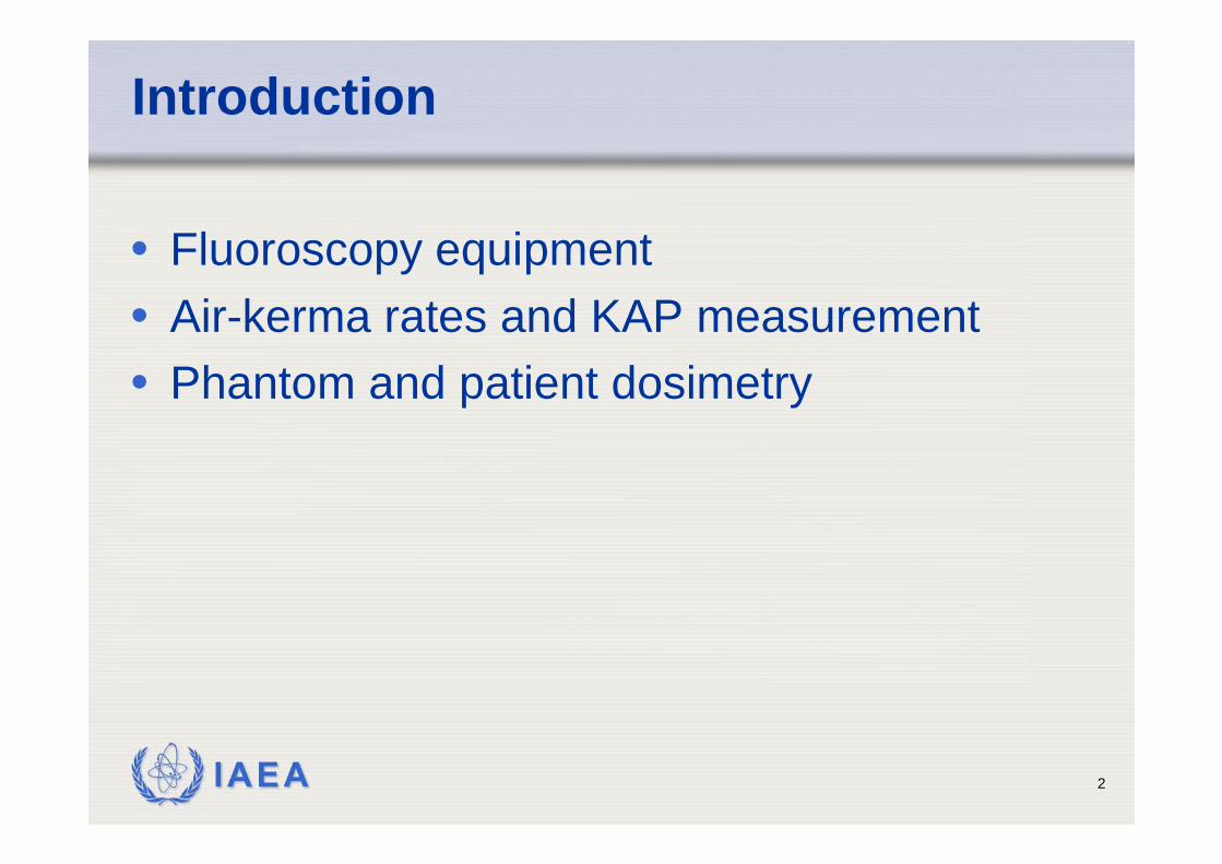
• Used to visualize motion of internal fluid, structures
• Operator controls activation of tube and position over patient
• Early fluoroscopy gave dim image on fluorescent screen
• Physician seared in dark room• Modern systems include image
intensifier with television screen display and choice of recording devices
Fluoroscopy: a “see-through” operation with motion
IAEA 4
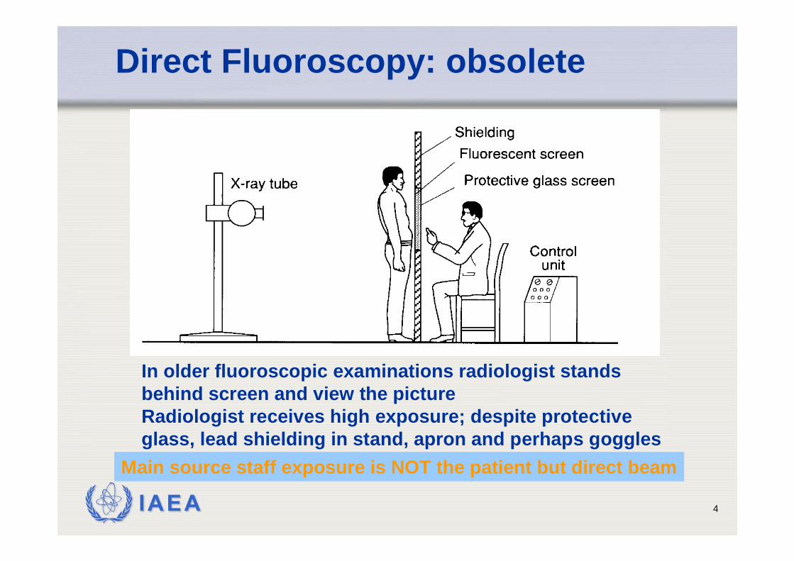
Direct Fluoroscopy: obsolete
In older fluoroscopic examinations radiologist stands behind screen and view the pictureRadiologist receives high exposure; despite protective glass, lead shielding in stand, apron and perhaps goggles
Main source staff exposure is NOT the patient but direct beam
IAEA 5
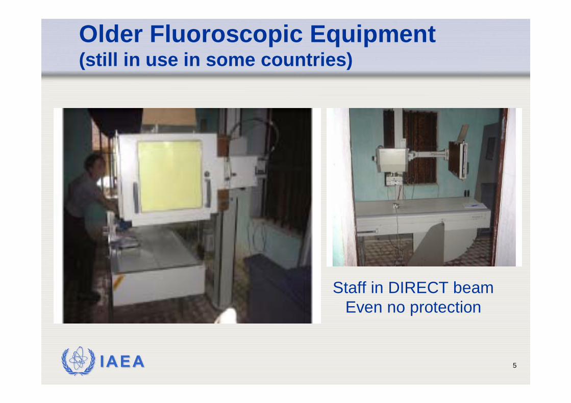
Older Fluoroscopic Equipment(still in use in some countries)
Staff in DIRECT beamEven no protection
IAEA 6
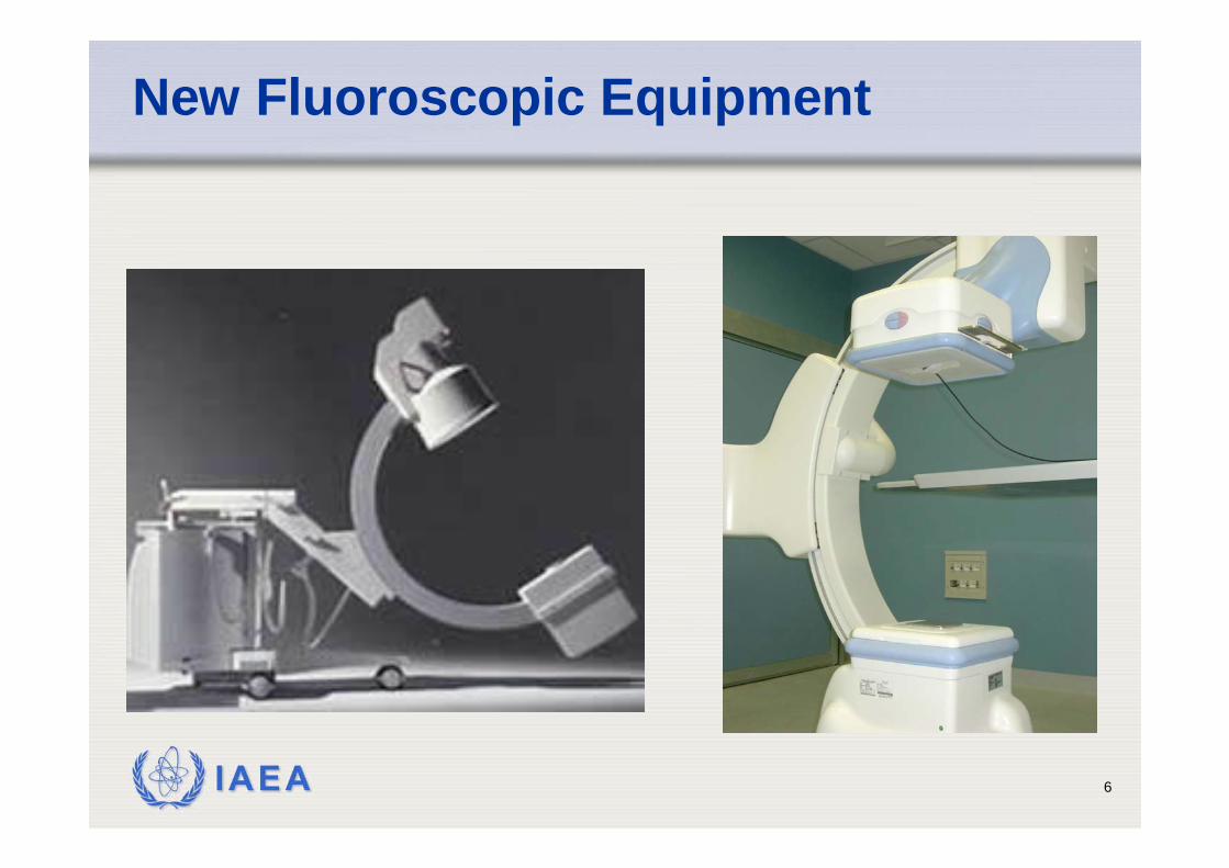
New Fluoroscopic Equipment
IAEA 7
• AVOID USE OF DIRECT FLUOROSCOPY• Directive 97/43Euratom Art 8.4.
• In the case of fluoroscopy, examinations without an image intensification or equivalent techniques are not justified and shall therefore be prohibited.
• Direct fluoroscopy will not comply with BSS App.II.25 • “… performance of diagnostic radiography and
fluoroscopy equipment and of nuclear medicine equipment should be assessed on the basis of comparison with the guidance levels
Direct fluoroscopy
IAEA 8
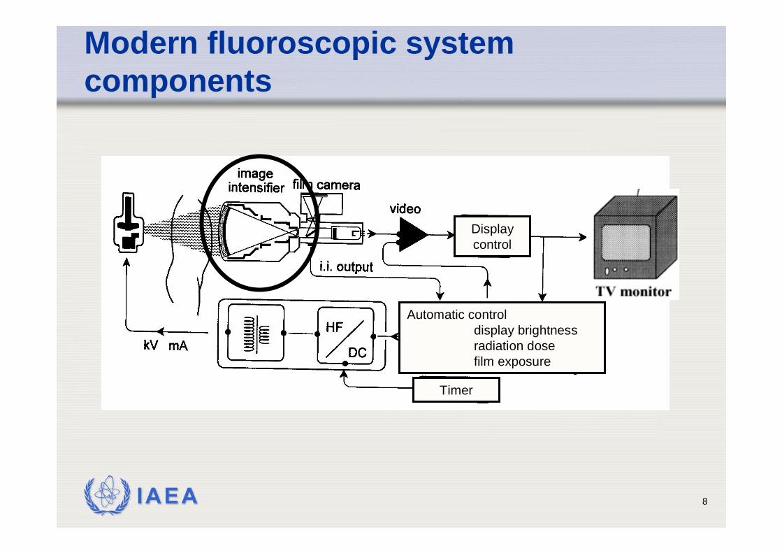
Automatic controldisplay brightnessradiation dosefilm exposure
Timer
Display control
Modern fluoroscopic system components
IAEA 9
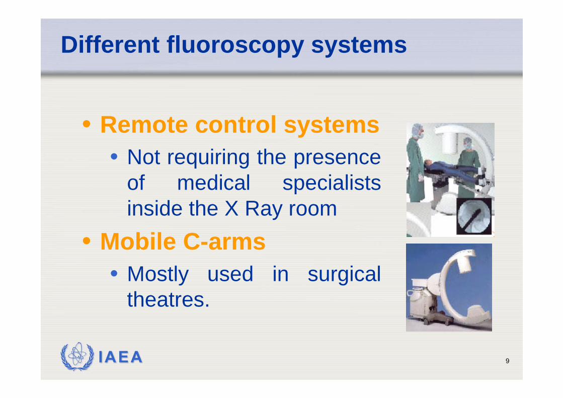
Different fluoroscopy systems
• Remote control systems• Not requiring the presence
of medical specialists inside the X Ray room
• Mobile C-arms• Mostly used in surgical
theatres.
IAEA 10
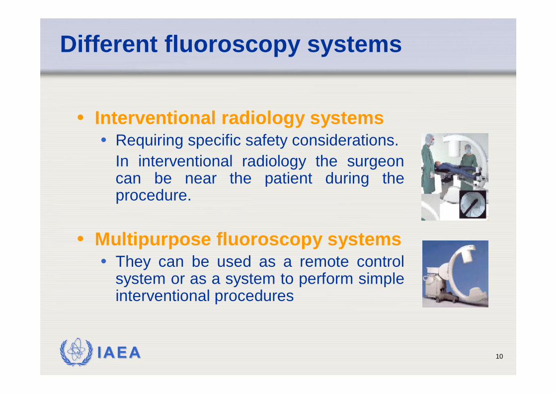
Different fluoroscopy systems
• Interventional radiology systems• Requiring specific safety considerations.
In interventional radiology the surgeon can be near the patient during the procedure.
• Multipurpose fluoroscopy systems• They can be used as a remote control
system or as a system to perform simple interventional procedures

IAEA 11
The image intensifier (I.I.)
+
I.I. Input Screen
I.I.Output Screen
Photocathode
Electrode E1
Electrode E3
Electrode E2
Electrons Path
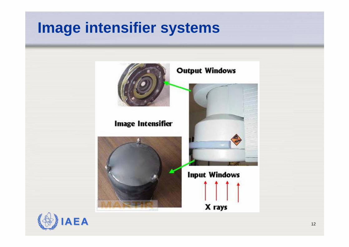
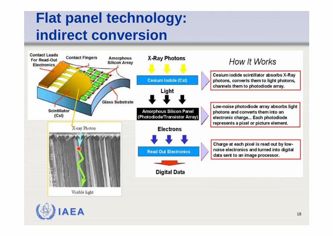
• Input screen: conversion of incident X Rays into light photons (CsI)
• 1 X Ray photon creates ≈3,000 light photons
• Photocathode: conversion of light photons into electrons
• only 10 to 20% of light photons are converted into photoelectrons
• Electrodes : focalization of electrons onto the output screen
• electrodes provide the electronic magnification
• Output screen: conversion of accelerated electrons into light photons
IAEA 12
Image intensifier systems
IAEA 13
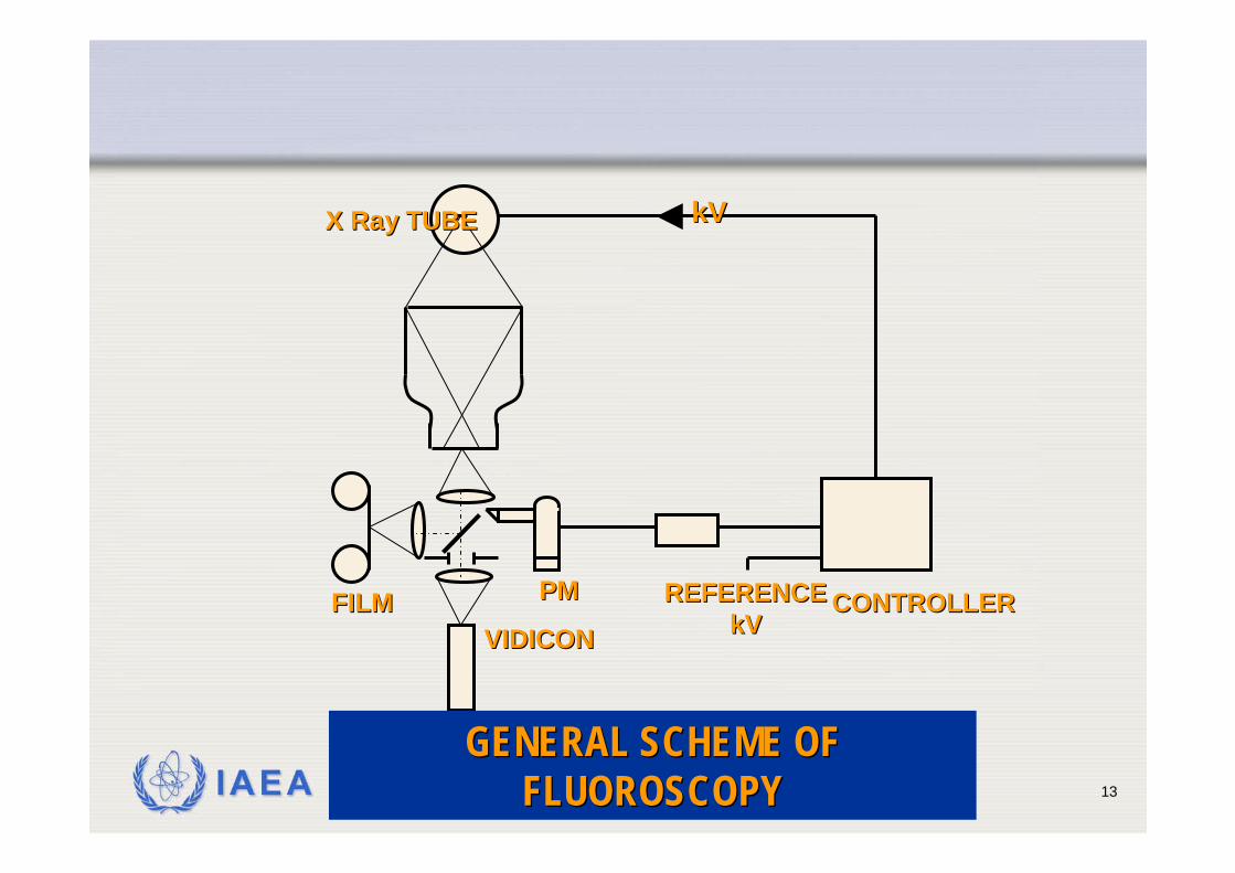
VIDICONVIDICONFILMFILM PMPM REFERENCEREFERENCE
kVkVCONTROLLERCONTROLLER
X Ray TUBEX Ray TUBE kVkV
GENERAL SCHEME OF GENERAL SCHEME OF FLUOROSCOPYFLUOROSCOPY
IAEA 14
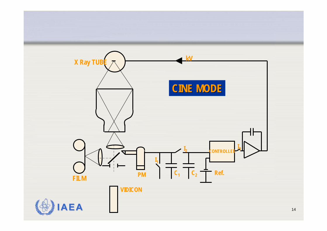
VIDICON
FILM PM
CONTROLLER
X Ray TUBE kV
CINE MODECINE MODE
I2
Ref.
I3
C1
I1
C2
IAEA 15
Type of TV camera
VIDICON TV cameraimprovement of contrastimprovement of signal to noise ratio high image lag
PLUMBICON TV camera (suitable for cardiology)lower image lag (follow up of organ motions)higher quantum noise level
CCD TV camera (digital fluoroscopy)digital fluoroscopy spot films are limited in resolution, since they depend on the TV camera (no better than about 2 lp/mm) for a 1000 line TV system
IAEA 16
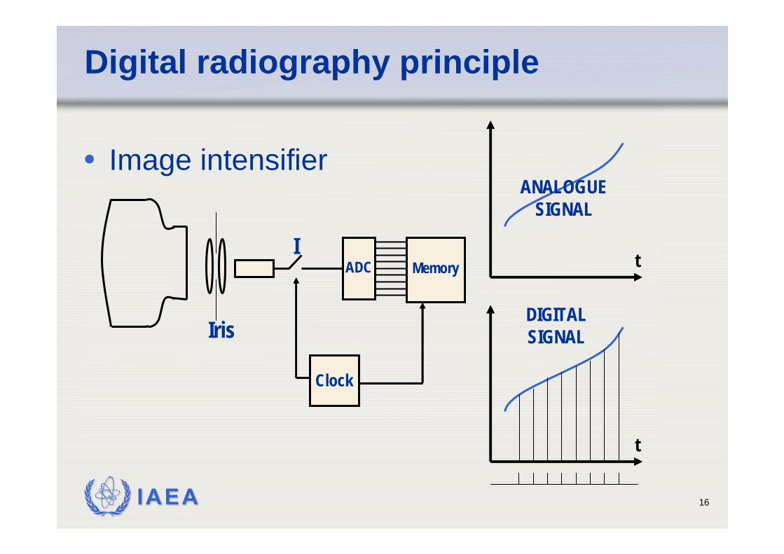
Digital radiography principle
• Image intensifier
Clock
MemoryADCI
Iris
t
t
ANALOGUESIGNAL
DIGITALSIGNAL
IAEA 17
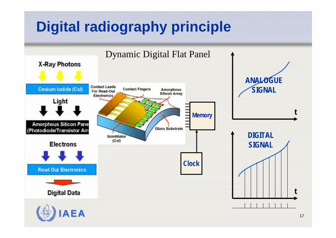
Digital radiography principle
MemoryADC t
t
ANALOGUESIGNAL
DIGITALSIGNAL
Clock
Dynamic Digital Flat Panel
IAEA 18
Flat panel technology: indirect conversion
IAEA 19
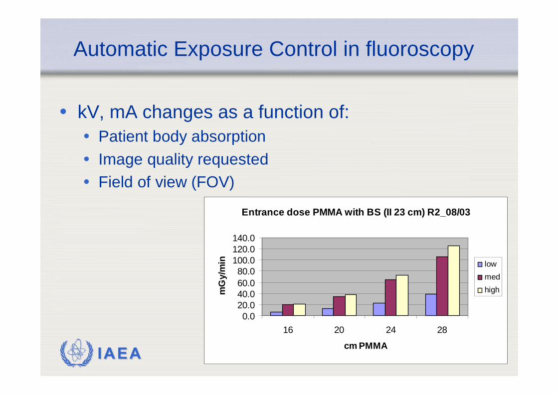
Entrance dose PMMA with BS (II 23 cm) R2_08/03
0.020.040.060.080.0
100.0120.0140.0
16 20 24 28
cm PMMA
mG
y/m
in lowmedhigh
Automatic Exposure Control in fluoroscopy
• kV, mA changes as a function of:• Patient body absorption• Image quality requested• Field of view (FOV)
IAEA 20
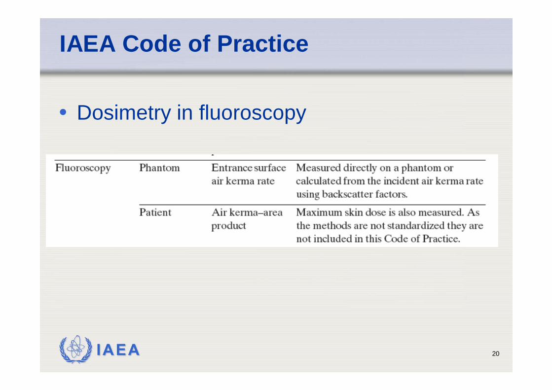
IAEA Code of Practice
• Dosimetry in fluoroscopy
IAEA 21
Dosimetry in fluoroscopy
• Quality assurance• Acceptance and constancy test
• air kerma rate for different acquisition modalities
• Patient dosimetry• Comparison with reference levels
• Air kerma area product• Dose analogues: fluoroscopy time and no. of
acquired images• Organ dose evaluation
IAEA 22
CoP
• Entrance surface air kerma rate is the principal quantity to be measured in fluoroscopy using phantoms.
• For measurements on patients, the air kerma–area product, a readily measuredquantity closely related to the energyimparted to the patient and to the effectivedose, is the recommended dosimetricquantity.
IAEA 23
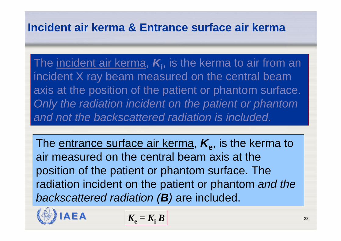
Incident air kerma & Entrance surface air kerma
The incident air kerma, Ki, is the kerma to air from an incident X ray beam measured on the central beam axis at the position of the patient or phantom surface. Only the radiation incident on the patient or phantom and not the backscattered radiation is included.
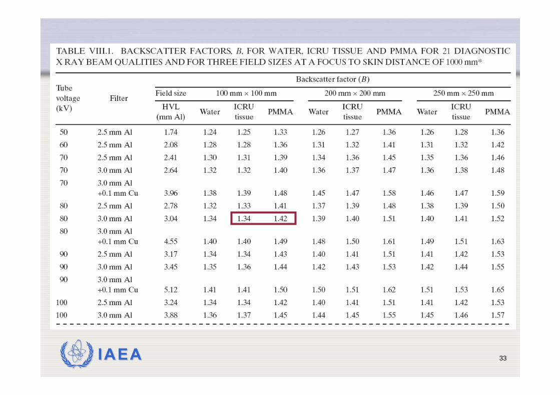
The entrance surface air kerma, Ke, is the kerma to air measured on the central beam axis at the position of the patient or phantom surface. The radiation incident on the patient or phantom and the backscattered radiation (B) are included.
Ke = Ki B
IAEA 24
Measurements using phantoms
• The entrance surface air kerma rate is measuredusing a water phantom or a PMMA phantom. • It is important that the detector responds to both direct
as well as backscattered radiation. • For detectors that do not respond to backscatter, the
entrance surface air kerma rate is calculated from the incident air kerma rate and an appropriate backscatterfactor. Semiconductor detector systems often possessthis property
IAEA 25
Equipment
• Diagnostic dosimeter calibrated for beam qualitiesused in fluoroscopy
• Water phantom of 20 cm thickness and cross-section of 30×30 cm2; • additional water phantom (or PMMA) of 10 cm thickness
for simulation of larger patients• Or 185 cm thick PMMA phantom (correction factor
for the different backscatter properties of PMMA)• Ruler, Thermometer and barometer (for
measurements with an ionization chamber)
IAEA 26
Method
• The fluoroscopic unit should be operated under automatic brightness Control (ABC).
• ABC has to be stabilized before measurements• Measurements for all image intensifier field sizes
(FOV), dose rates and automatic brightnesscontrol options (image quality) reflecting normalclinical use. • The focus to intensifier and focus to chamber distances,
tube voltage, tube current and any filtration selectedshould be recorded for each measurement.
• The measurements are strongly dependent on the relative positions of the X ray tube, patient entrancesurface and image intensifier.
IAEA 27
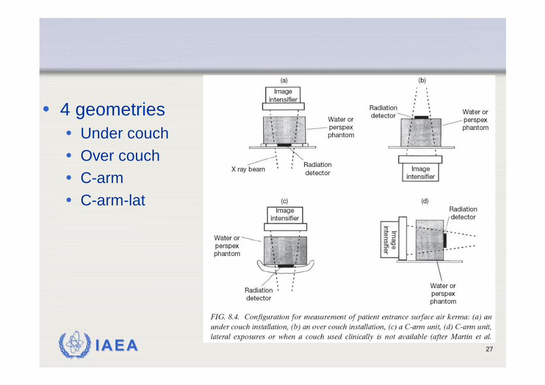
• 4 geometries• Under couch• Over couch• C-arm• C-arm-lat
IAEA 28
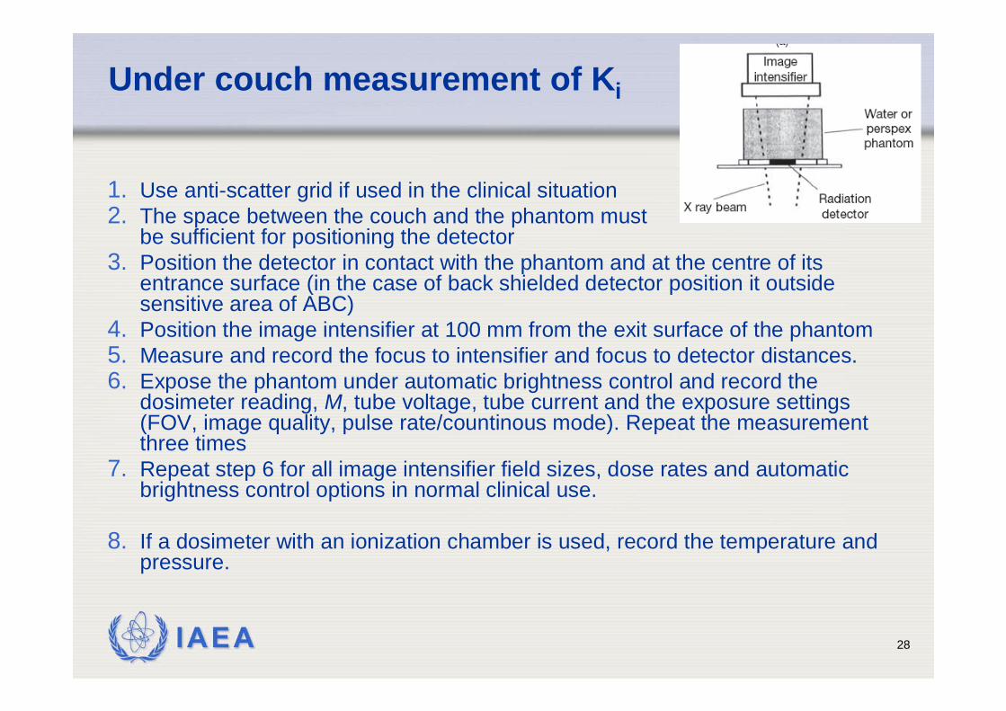
Under couch measurement of Ki
1. Use anti-scatter grid if used in the clinical situation2. The space between the couch and the phantom must
be sufficient for positioning the detector3. Position the detector in contact with the phantom and at the centre of its
entrance surface (in the case of back shielded detector position it outsidesensitive area of ABC)
4. Position the image intensifier at 100 mm from the exit surface of the phantom5. Measure and record the focus to intensifier and focus to detector distances.6. Expose the phantom under automatic brightness control and record the
dosimeter reading, M, tube voltage, tube current and the exposure settings(FOV, image quality, pulse rate/countinous mode). Repeat the measurementthree times
7. Repeat step 6 for all image intensifier field sizes, dose rates and automaticbrightness control options in normal clinical use.
8. If a dosimeter with an ionization chamber is used, record the temperature and pressure.
IAEA 29
Other geometries (differences)
• Over couch• Set the focus to couch (table top) distance equal
to that used in clinical practice. If a standard distance is to be used, set the focus to couchdistance equal to 1000 mm
• C-arm & C-arm lateral proj• Set the distance between the X ray focus and
the image intensifier to 1000 mm (if this distancecan be varied).
IAEA 30
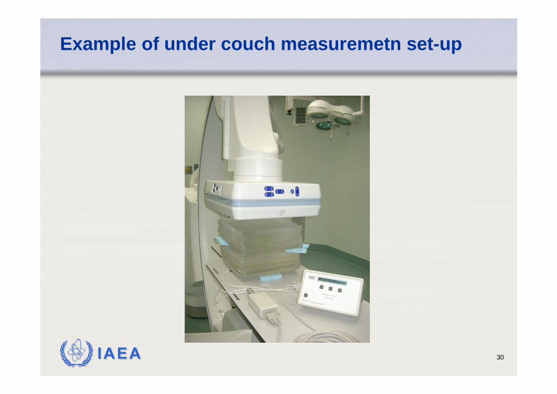
Example of under couch measuremetn set-up
IAEA 31
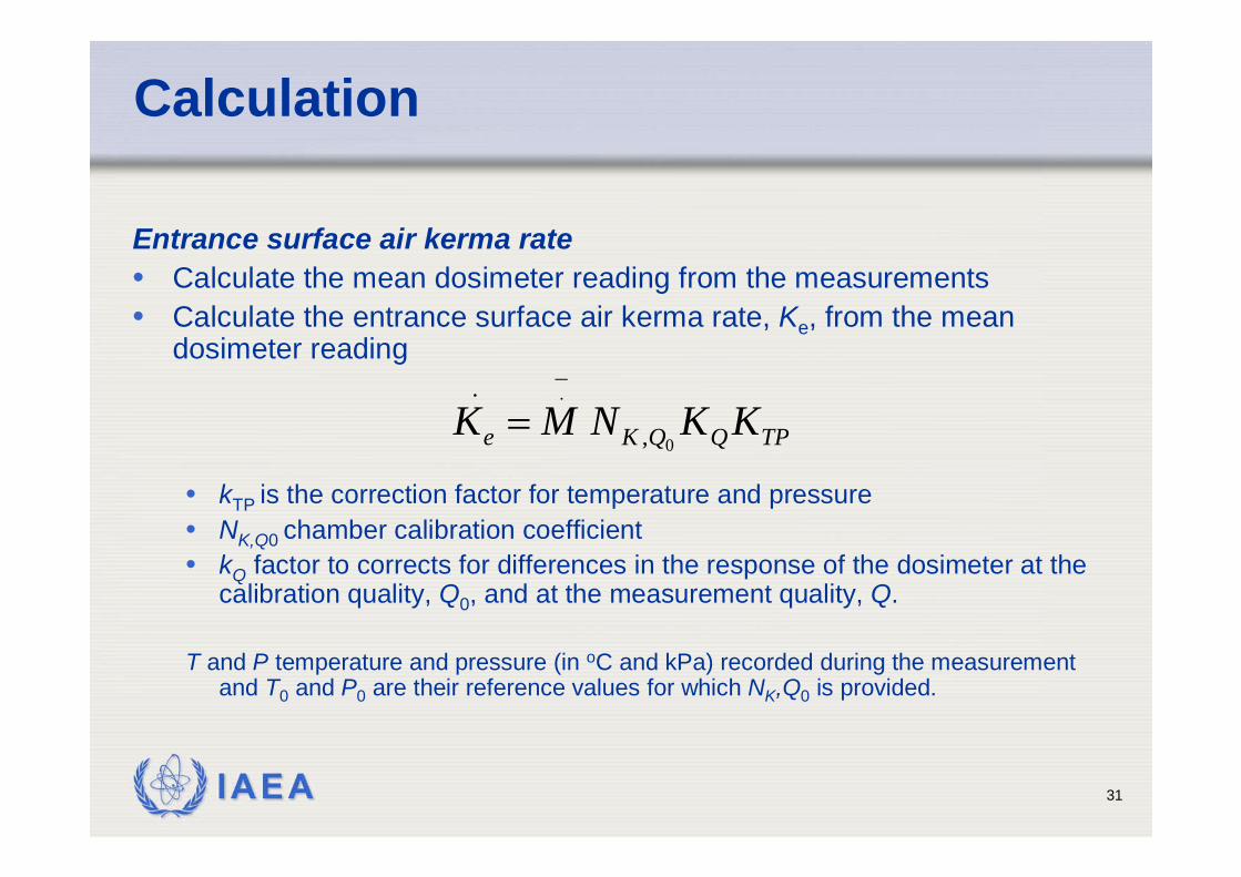
Calculation
Entrance surface air kerma rate• Calculate the mean dosimeter reading from the measurements• Calculate the entrance surface air kerma rate, Ke, from the mean
dosimeter reading
• kTP is the correction factor for temperature and pressure• NK,Q0 chamber calibration coefficient• kQ factor to corrects for differences in the response of the dosimeter at the
calibration quality, Q0, and at the measurement quality, Q.
T and P temperature and pressure (in oC and kPa) recorded during the measurementand T0 and P0 are their reference values for which NK,Q0 is provided.
TPQQKe KKNMK0
.
,
_.=
IAEA 32
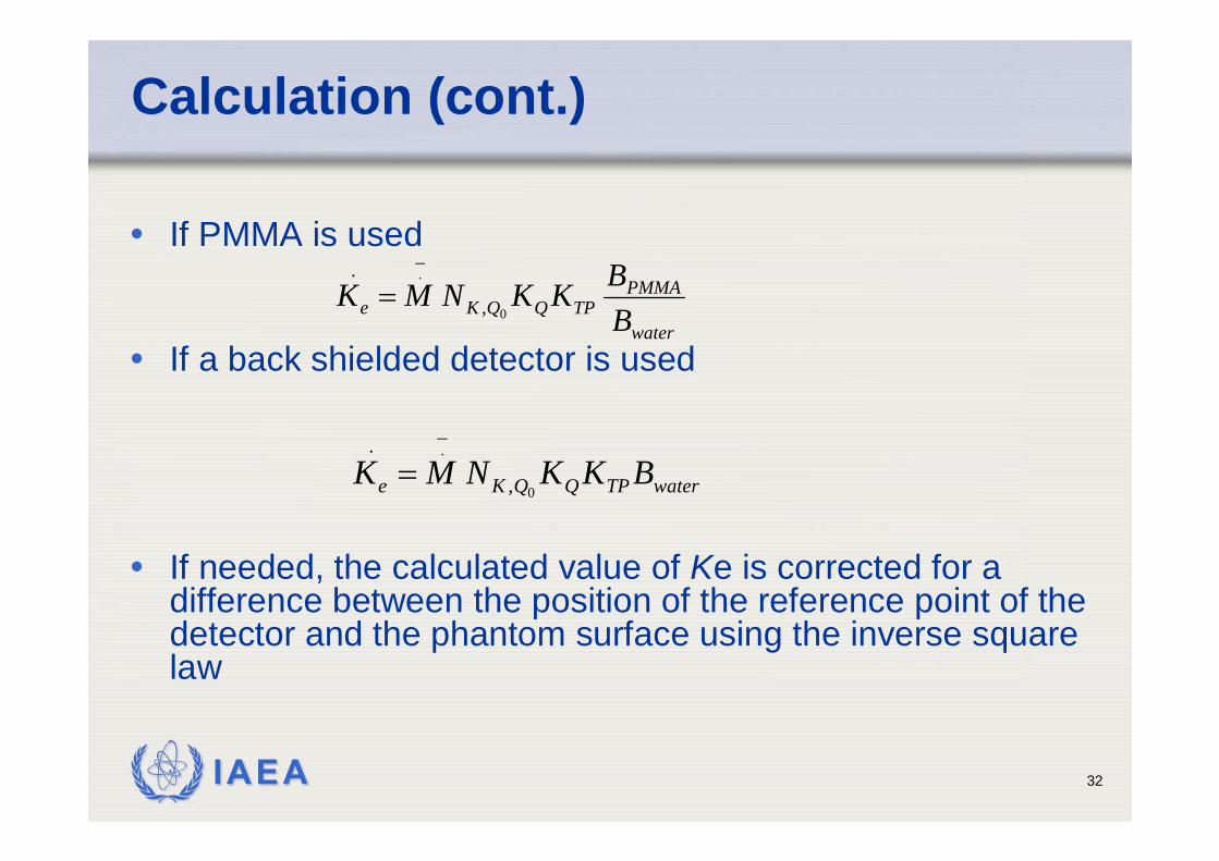
Calculation (cont.)
• If PMMA is used
• If a back shielded detector is used
• If needed, the calculated value of Ke is corrected for a difference between the position of the reference point of the detector and the phantom surface using the inverse squarelaw
water
PMMATPQQKe B
BKKNMK0
.
,
_.=
waterTPQQKe BKKNMK0
.
,
_.=
IAEA 33
IAEA 34
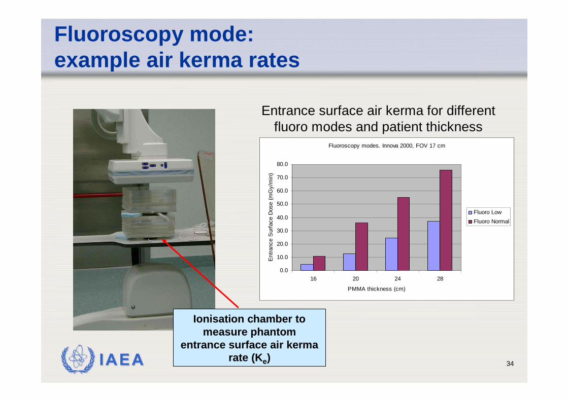
Fluoroscopy mode: example air kerma rates
Ionisation chamber to measure phantom
entrance surface air kerma rate (Ke)
Fluoroscopy modes. Innova 2000, FOV 17 cm
0.0
10.0
20.0
30.0
40.0
50.0
60.0
70.0
80.0
16 20 24 28
PMMA thickness (cm)
Ent
ranc
e S
urfa
ce D
ose
(mG
y/m
in)
Fluoro LowFluoro Normal
Entrance surface air kerma for different fluoro modes and patient thickness
IAEA 35
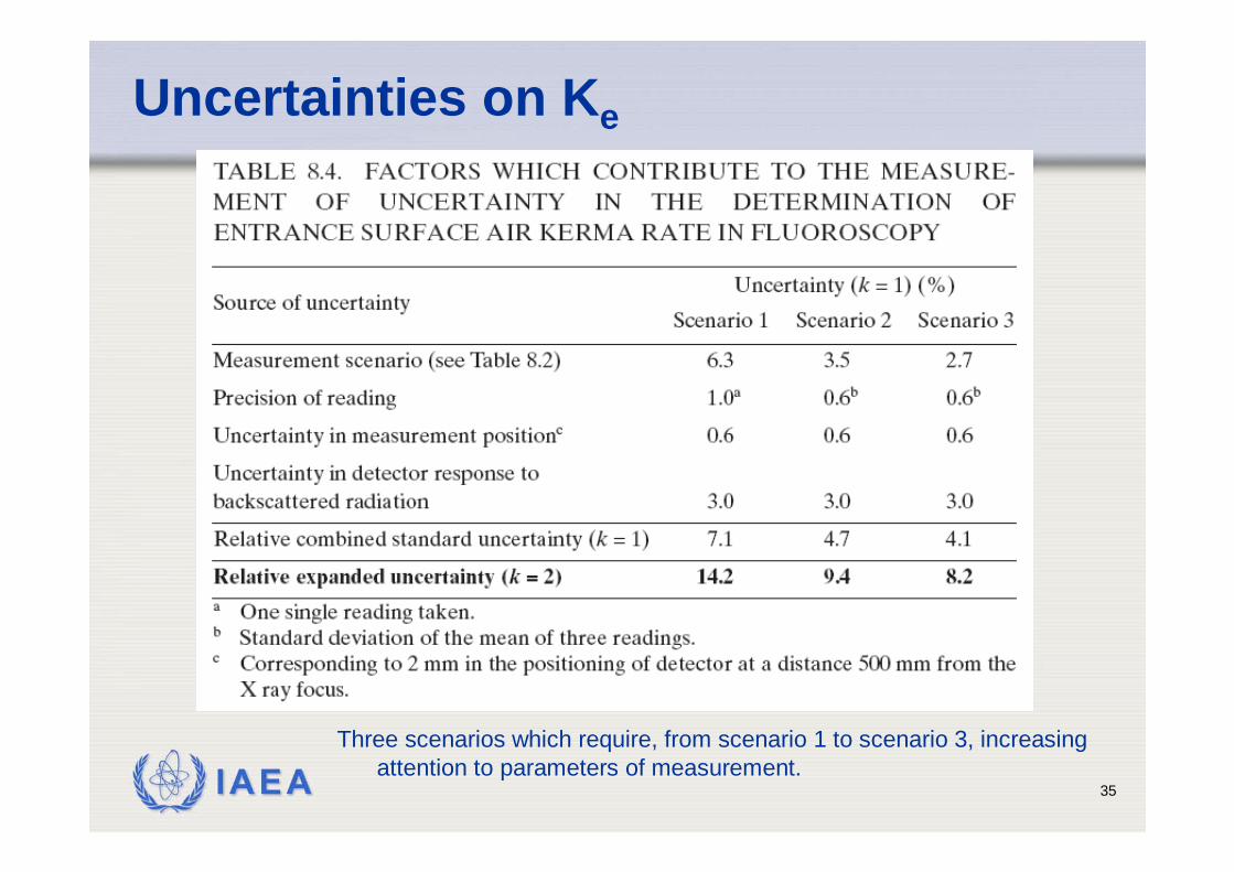
Uncertainties on Ke
Three scenarios which require, from scenario 1 to scenario 3, increasingattention to parameters of measurement.
IAEA 36
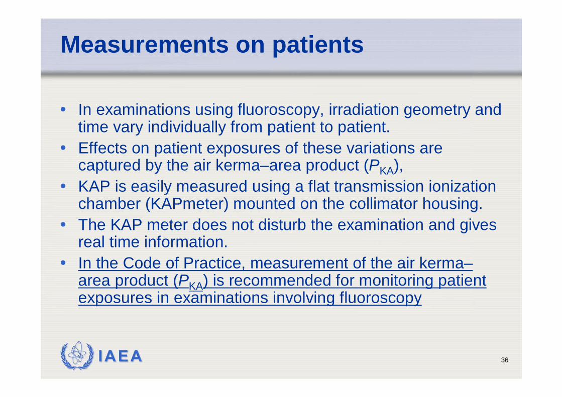
Measurements on patients
• In examinations using fluoroscopy, irradiation geometry and time vary individually from patient to patient.
• Effects on patient exposures of these variations are captured by the air kerma–area product (PKA),
• KAP is easily measured using a flat transmission ionizationchamber (KAPmeter) mounted on the collimator housing.
• The KAP meter does not disturb the examination and givesreal time information.
• In the Code of Practice, measurement of the air kerma–area product (PKA) is recommended for monitoring patientexposures in examinations involving fluoroscopy
IAEA 37
Air kerma-area product
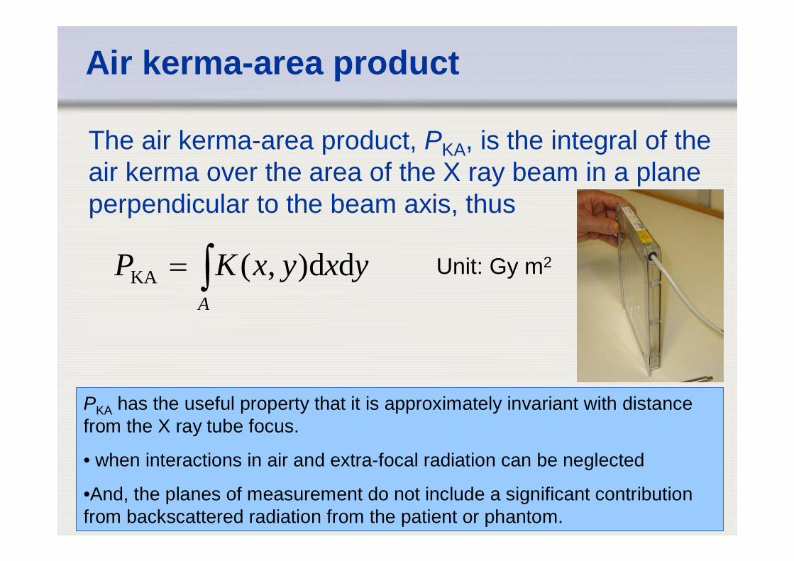
The air kerma-area product, PKA, is the integral of the air kerma over the area of the X ray beam in a plane perpendicular to the beam axis, thus
∫=A
yxyxKP dd),(KA Unit: Gy m2
PKA has the useful property that it is approximately invariant with distance from the X ray tube focus.
• when interactions in air and extra-focal radiation can be neglected
•And, the planes of measurement do not include a significant contribution from backscattered radiation from the patient or phantom.
IAEA 38
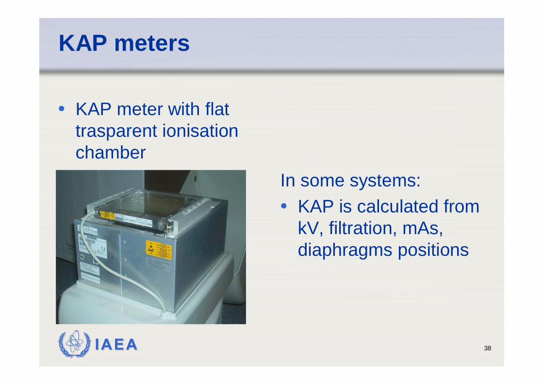
KAP meters
• KAP meter with flattrasparent ionisationchamber
In some systems: • KAP is calculated from
kV, filtration, mAs, diaphragms positions
IAEA 39
Measurement on patient
1. Mount the KAP meter on the exit surface of the collimatorhousing of the X ray tube. This step is omitted in the case of a built-in KAP meter.
2. Record, if possible, the tube voltage and any othermachine parameters (e.g. operating mode chosen, tube current and pulse rate if appropriate) used during the examination.
3. Record the reading, M, of the KAP meter.4. If the operating mode is changed during the procedure, it
may be helpful to use recorded KAP meter readings (ifavailable) and machine parameters for each stage.
5. Record the temperature and pressure.
IAEA 40
IAEA Code of Practice: Patient selection
• It is important that the size of a sample of patientsis sufficiently large as to avoid large statisticalvariations of the mean value of the measuredquantity.
• Care has to be paid also to the selection of patients according to their anatomical parameters(e.g. weight). A range of 10–50 patients for the sample size can be found in the literature.
• Selection of patients so that the mean weight of the sample lies within 5 kg of 70 kg or within 5 kg of 60 kg in some geographical regions has beenshown to be sufficient
IAEA 41
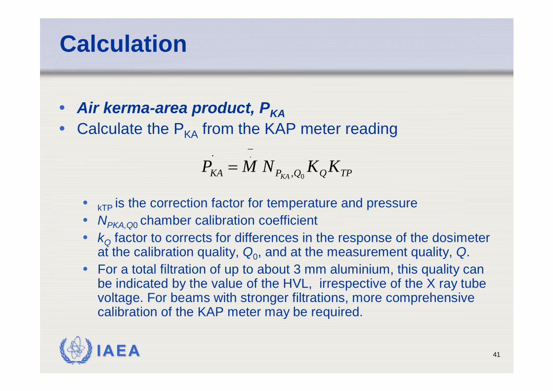
Calculation
• Air kerma-area product, PKA• Calculate the PKA from the KAP meter reading
• kTP is the correction factor for temperature and pressure• NPKA,Q0 chamber calibration coefficient• kQ factor to corrects for differences in the response of the dosimeter
at the calibration quality, Q0, and at the measurement quality, Q. • For a total filtration of up to about 3 mm aluminium, this quality can
be indicated by the value of the HVL, irrespective of the X ray tube voltage. For beams with stronger filtrations, more comprehensivecalibration of the KAP meter may be required.
TPQQPKA KKNMPKA 0
.
,
_.=
IAEA 42
Uncertainties
• The uncertainty in the calibration coefficient when the tube voltage and filtration are known and the energydependence accounted for can be reduced to about 6% at the 95% confidence level.
• IEC 60580 specifies acceptable limits of uncertainty in the response of KAP meters when individual exposureparameters (influence quantities) vary• the estimated uncertainty of a measurement with KAP meters is
25% at the 95% confidence interval (k = 2) • this corresponds to a single value for the calibration coefficient
representing all factors, i.e. all possible doses, dose rates and X rayenergies in clinical practice,
PKA rate (10–2 –1.5 × 10⁴) μGy·m2·s–1
X ray spectrum (50–150) kV, total filtration 2.5 mm Al
IAEA 43
Uncertainties
• If a calibration coefficient has only beenestablished for an over couch situation, the insertion of a table with a mattress in the beamreduces the air kerma incident on the patient by up to 15–40%, depending on • the HVL of the beam, • beam angulations• and table construction
• This has to be considered when using the KAP toestimate patient exposure
IAEA 44
KAP meter calibration
• The KAP meters should be calibrated for eachstand where they are used.
• Calibrations both in situ and at a standard laboratory are possible.
• Modern radiology departments usually possess a number of machines with KAPs. It is not realistic tocalibrate each instrument at the SSDL and forbuilt-in KAP meters this is not even possible.
• The calibration coefficient provided by the manufacturer should be checked before the instrument is used.

IAEA 45
Friuli-Venezia Giulia region
Mandi!
Thank you!Udine
Recommended