20SH.8
DEPARTMENT Of CWIl ENGINEERINGFRITZ ENGINEERING LABORATORY
LEHIGH UNIVERSITY''G; BETHLEHEM, PENNSYLVANIA
-1-
/
PROPOSAL FOR THE CONTINUATION OF TESTS
ON IATERAL BRACING REQUIREMENTS
1 0 Introduction~
An experimental program on the lateral bracing
requirements for beams in plastically designed continuous
frames has been in progress at Fritz Engineering Laboratory
since March 1960 0 Two proposals have been sUbmitted~1)(2~
for approval of the Lehigh Project Subcommittee of the
Welding Research Council, and the work which was proposed. .
. has been essentially completed. This proposal is submitted
to extend the work o
..J' The objectives. of this experimental program are
to determine:
1 0·.The post-buckling strength and rotation
capacity of wide flange beams o
20 The required optimum spacing of the
lateral bracing o
(1) "Proposal of Tests for the Lateral Bracing ;~equirements
of Plastically Designed Beams"o Fritz Lab. Report No.20SH.3, March 18, 1960".
(2) "Proposal for Further Tests on the Lateral Bracing Requirementsof Beams". Fritz Lab. Report No. 20SH.7, JaB-uary 10, 1961.

205H.8 -
, '
-2~
3. The required strength and stiffness
of the lateral bracing.
The influence of the following variables were
planned to be investigated:
1. Beam size,'
2. Critical unbraced length under uniform moment,
3. Length of adjacent spans
4. Strength and stiffness of purlin,
5. Type of purlin,
6. Methods of purlin attachment,
7. Dead load on purlins,
8. Critical unbraced length under moment gradient,
9. Number of adjacent critically loaded spans.
In the completed experimental program a sufficient
number of tests have been performed to form conclusions on
the effects of all of these variables except on the effect
. of the dead load on the purlin, moment gradient, and the number
of critical spans. The present proposal contains a program of
tests to investigate the effect of the last two of these
variables.
The results of the completed work are discussed in
205H.8
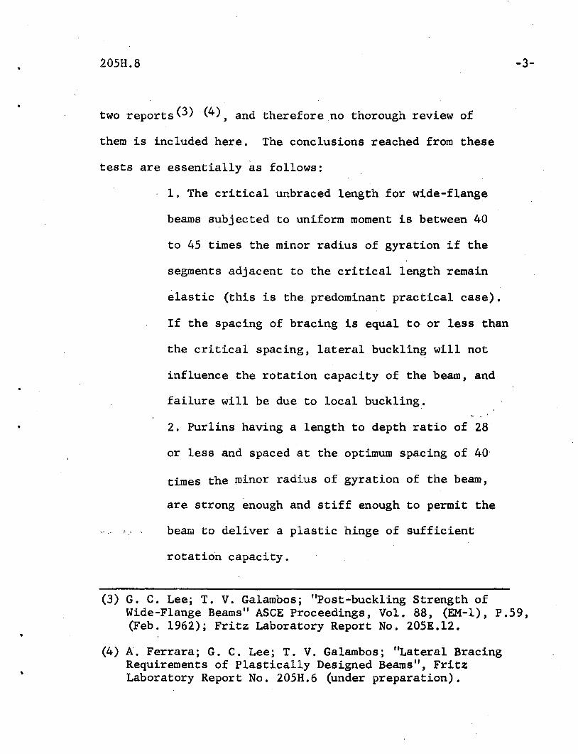
two reports(3) (4), and therefore no thorough review of
them is included here. The conclusions reached from these
tests are essentially as follows:
1. The critical unbraced length for wide-flange
beams subjected to uniform moment is between 40
to 45 times the minor radius of gyration if the
segments adjacent to the critical length remain
elastic (this is the predominant practical case).
If the spacing of bracing is equal to or less than
the critical spacing, lateral buckling will not
influence the rotation capacity of the beam, and
failure will be due to local buckling,.
2. Purlins having a length to depth ratio of 28
or less and spaced at the optimum spacing of 40'
times the minor radius of gyration of the beam,
are strong enough and stiff enough to permit the
'.' beam to deliver a plastic hinge of sufficient
rotation capacity.
-3-
(3) G. C. Lee; T. V. Galambos; "Post-buckling Strength ofWide-Flange Beams" ASCE Proceedings, Vol. 88, (EM-l), P.59,(Feb. 1962); Fritz Laboratory Report No. 205E.12.
(4) A. Ferrara; G. C. Lee; T. V. Galambos; "Lateral BracingRequirements of Plastically Designed Beams", FritzLaboratory Report No. 205H.6 (under preparation).

'205H. a -4-
3. Beams with purlins on one side only (end
frames in a multi-frame warehouse, for example)
require approximately twice the purlin stiffness
than beams with purlins on both sides (length
to depth ratio of 14 or less) in order to develop
plastic hinges with sufficient rotation capacity.
4. All of the methods of beam-to-purlin attachment
tested (that is, welded or bolted continuous or
discontinuous purlins) proved adequate.
In order to furnish a review of the completed tests,
the schematic test set-up is shown in Fig. 1 and the experi
ments with their principal variables are listed in Table 1
of this report.
2. Objective.
In all the tests performed so far, the span under
investigation was subjected to a uniform bending moment and the
adjacent spans were elastic. For a more detailed study of· the
problem of lateral bracing it is desired to perform additional
tests. One set of tests is proposed to evaluate the effect
of moment gradient on the· rotation capacity of a beam.
Another set of experiments is recommended to investigate

205H.8
the behavior of beams under uniform moment with yield~d
-5-
•
..
adjacent spans. Finally, it is desired to study the influence
of moment redistribution on the lateral bracing requirements
for a two span ,continuous beam.
3. Proposal.
It is proposed to perform 12 additional experiments)".
on wide-flange beams to be numbered tests G-l to G-12. These
12 experiments are subdivided into three sets depending on the
variables to be investigated. Tests G-l to G-8 constitute
the first set, and they are designed to investigate the
effect of moment gradient on the rotation capacity of the beam.
Tests G-9 to G-ll constitute the second set, and are
designed to study the influence of inelastic adjacent spans.
Test G-12 is proposed to study the effect of moment re-, ,
distribution on the lateral bracing requirements for a two
span, continuous beaIl!~ Table 2 lists the test numbers,
beam size, lengths of critical and adjacent spans, moment
gradient and purpose of each test. The test set-up, data,
instrumentation and test procedure will be essentially the same
as in the previous program. A schematic, diagram of· the
,general test set-up is shown in Figs. 2 and 3 •

205H.8 -6-
The first 8 tests (G-l to G-8) are proposed to study
•
the effect of moment gradient and bracing spacing of the
rotation capacity of plastically designed beams. Figures 4
and 5 give the schematic diagrams of the loading condition
and the moment diagrams respectively. The beams for these
eight tests are divided into 4 equal spans by 5 sets of
lateral supports, and the middle two spans will be under
investigation. The specimens in tests G-l to G-4 will be
supjected to a moment gradient of +0.5. Based on an
approximate analysis (5) , the unbraced length for test G-l
has been chosen as 50ry ' The unbraced lengths for tests
G-2 to G-4' have been left open and will be decided upon after
the completion of the test G-l. Tests G-5 to G-8 will be for
a moment gradient of zero. Based on the same considerations
as above, the unbraced length for test G-5 has been fixed
as ~O~y. The unbraced length for tests G-6 to G-8 has been
left open and will b~ decided upon completion of test G-S.
(5) T. Kusuda; R. G. Sarubbi; B. Thurlimann; "The Spacingof Lateral Bracing in Plastic Design" Fritz LaboratoryReport No. 20SE.ll.

205H.8
Tests G-9 to G-ll are proposed to study the influence
of plastic adjacent spans on the rotation capacity of beams.
The moment diagram and a schematic view of the loading system
for these tests is shown in Fig. 6. The beams will be
divided into 5 equal spans braced laterally at point A, B,
C~ D~ E,l and F ~ with the middle span (CD) as the '~r'~~ical_ I ~, .
segment. As can be seen from the moment diagram,the span
adjacent to CD will also be subjected to plastic moment.
The unbraced length for test G-9 has been fixed at40ry
as this length has been found satisfactory with uniform
moment gradient and elastic adjacent spans. For test G-10
andG-ll, the unbraced length has been left open and will be
decided upon completion of test G-9.
Test G-12 is proposed to study the influence of
moment redistribution on the lateral bracing requirements of
a two span continuous beam. Fig. 6 shows the moment diagram,
length of spans, and points of lateral bracings for this test.
It can be seen from Fig. 6 that the first plastic hinge will
be formed when the moment at point B becomes the p~astic
moment. With increase in load, moment redistributi6n will'.
take place, and another plastic hinge will be formed at C.
"

205H.8
;
-8-
•
The unbraced length will be determined from test G-l to G-8.
In all proposed tests the lateral supports will
consist of 1/2 inch plates bolted to 5" channels which will
in turn be welded to a base plate. To create a knife-edge
condition, 1/2" diameter rods will be welded to the edge
of the plate. The distance between the two 1/2" diameter
rods will be made adjustable by ,slotted holes in the
channels. The test specimen will be guided between these
knife-edges. These supports will permit lateral rotation
but will prevent twisting and lateral motion of the beam at
the support points. All lateral supports will be fastened to
the top flange of a heavy base beam which will be fixed to the
laboratory floor. To minimize the effect of friction, the knife
edges as well as the contact surface on the beam will be milled
and heavily greased before each test.
4. Financing
The cost of these proposed experiments is contained
in the regular budget for project 205H, and therefore no
additional funds are requested.

Test Beam LeX' Ladj Purlin Purlin lId Purpose of testNo o Size Size Length
LB~lO lOWF25 45ry 45ry Full _. ~ ~ Qetermination-of un~Support braced span length
LB~ll " 35ry 35ry " - - "LB~15 " 40ry 40ry " - ~ "LB-16 " 50ry 5~ry " - '" "
--LB~ll " :lOry 17.5ry " - '" ~ determinationLB-12 " 40ry 40ry 417.7 . 84" 21 Determination of Purlin
Size
LB-13 " " " 315.7 " 28 "LB-14 " " " M2362 " 32 "LB~18 " " " 315 0 7 " 28 Determination of Purlin
Slenderness
LB-19 " " " " 148" 4903 "LB-20 " " " " 116" 38.7 "LB-21 " " " " 84" 28 Purlin on one side only,
LB-22 " " " " 56" 1807 "
TABLE 1.
NoVI=:.
o\0e

. ..
Test Beam Lcr Ladj Purlin FUrlin lId Purpose of testNo. Size " ,S;z,e Length
"." ,
"Full"..
P~l lOWF25 20ry 20ry ~ =~ determination
.' Support,.
~ '" ,- ."
P-2 8B13 20ry 20ry " - - "' ..
P-3 " 40ry ~Ory M2362 73.5" 28 Effect of beam size.. .. .. '''': ...-
p~4 " " 60r " " " Effectof,the length ofy- adjacent span
..-"
P~6 lOWF25 " 40ry 3I5.7 84" 28 Effect .. of Purlins to beam- connections
P-7 " " " " " " "P-8 " " " " " " "P-9 " " " " " " Effect of half stiffners
P...1O " " " " 56" " Purlins on one side only
TABLE 1 (continued)
No\J1::c•00
It-'o6

205H.8 -11-
Test Beam Critical Adj. Mom. Remarks . Fig.No. Section Span Span Grad. ' No.
G-l 10B15 50ry 50ry +0.5 Effect of
G-2 II * * II. momentgradient ·'on
G-3 II * * II the rota- - 4tion capa-
G-4 II * * II city of.the beam
G-5 II 60ry 60ry zero----
G-6 II ** ** II
II 5G-7 " ** ** "
I
G-8 II ** ** II
G-9 " 40r 40ry +1.0 Effect ofy
" *** IIInelastic
6G-10 *** adjacent
G-ll 'I *** *** IIspan
Two spancontinuous
G-12 II 50ry 50ry " beam with 7load at thecenter of
I one of them
* To be determined after complet;ion of Test G-l.** To be determ}ned after completion of Test G-5.
*** To be determined after completion of Test G-9.
• 10B15: b/t= 14.85 d/w'= 43.5
TABLE 2.

20511.8'I -12-
P Rod Rod P•
Ajf
Cl+
BI 10WF25 DI
===::1 M = PL ,--------~~'___. ~=PL~
I__~__L__~~.--,Lc=r_---,+>--__L I
Lateral Bracings at Section A, B, C, and D.
For test Nos. LB-9, LB-10, LB-ll, LB-15) LB-16, and LB-17.
(a)
P P
•A
~ R
B 10WF25 C D,...
~t~
S S
M = PL
LL Lcr~-------l+r--------;+f----_~
R Points of Loading for LB-12, 13 and 14.
S Points of Loading for LB-18, 19 and 20.(b)
FIG. 1. SCHEMATIC TEST SET-UP AND MOMENT DIAGRAM
FOR TESTS ON BRACING REQUIREMENTS

.'
•
205H.8 -13-
---- ..n-Supporting Girder~ I I - =I i
i=rr'I[OJ' ~!II
~ ~Beam of---/ I :
Supporting I II
Frame ~-'i
t1II
Vertical II
Support- Column of IISupporting II
IIFrame--- ~.~
01 Loadin2 Jack....... ....
~nII 10 B 15 • ""'1'1 · . 1.L'l," •
Test Specime~ --LateralII- j 1II I
Bracings~ lJ II' I
I I ..+'-h'I ILL.
I ! ! I -rr..i I I I
II!i
',1' .,~ "l'·~Lab. ' '\'tenter FloorLine
FRONT VIEW
- -=---=.---=----=-~-=-~---=----~---=--------
'----Lateral Bracings----~
SECTION 1-1
FIG. 2. SCHEMATIC SKE~CH OF TEST SET-UP

.. . .. ..
-- _.-'
NoVI::t:.00
'J
"
SupportingI'Girder ,I
I, II ~Supporting1/ ,I GirderII=- =1
-~I PinIf"Cross Beam Jack III ),
II
~,II
III,
Roller II0 Test Beam II
Lateral 0IIBracing-. 0
I'"
I,tiffener IIIII
SECTION 2-2 SECTION 3-3
FIG. 3.
B.....~B

•
&
205:1.8
J1Ck ard JiCk
A1b:::==:=B=====:1======CI=D==='=1II.. Ladj ~+. tcr -~ lcr _1_ ladj ~
~Lateral Bracings at A, B, C, D, and E.
FIG. 4. SCHEMATIC DIAGRAM FOR TESTS G-l TO G-4.
MOMENT GRAD lENT.:: +0.5
Jack Rod Jack
BI cj •AI DI II~
Ladj -1-Lcr
-~Lcr + Ladj -I
~Lateral Bracing at A, B, C, D, and E.
FIG. 5. SCHEMATIC DIAGRAM FOR TESTSG-5 TO G-B.
MOMENT GRADIENT = ZERO.
-15-

,205H.8
Jack Rod Rod
-16=
Jack.
i t*A B C D E' F
}. ----1+ Ladj t_-L-c-r-----i--l_ Ladj t
lA B C D E F
• Lateral Bracingsat A, B, C, D, and E•
FIG. 6. SCHEMATIC SET-UP FOR TESTS G-9 TO G-ll •
•

,205H.S -17-
p
B C D E
ttA
I.. 50ry ,_ 50ry + 50ry -1- 50ry -j
•
•
Supports at A, C, and E.
Lateral Bracingsat A, B, C, D, and E.
FIG. 7. SCHEMATIC DIAGRAM OF TEST G-12.
•
t
Recommended