2217E
Keeping Industry Turning
Installation & MaintenanceW Ex db (eb) Zone 1 Flameproof motors
2
Installation & Maintenance
Introduction
WWaarrnniinnggThese motors are certified by a European
Notified Body for use in hazardous
atmospheres and should be installed,
maintained and repaired (if necessary), strictly
in accordance with the relevant standards and
codes of practice of the user country for the
repair and overhaul of Ex electrical apparatus.
(For example, in UK: EN 60079-19 and
recommendations outlined in the
BEAMA/AEMT ‘Code of Practice’ for repair and
overhaul of Ex electrical apparatus’).
The certificates issued apply to motors as
originally supplied, and in order to maintain
validity, it is essential that any servicing/ repair
be undertaken only by accredited
establishments (see paragraph on ‘Spares and
Repairs’). Only genuine replacement parts can
be used on these certified motors - always
specify motor serial number, output (kW), RPM,
voltage, Hz and mounting when ordering
spares.
WWaarrnniinnggQualified personnel only must undertake
handling and lifting of electric motors. See
additional sections of this manual and the
customer safety and installation instructions.
Full product documentation and operating
instructions must be available together with
tools and equipment necessary for safe
working practice.
Note - before any work commences, reference
should be made to the warning paragraph at
the top of this page.
RReecceeiippttBefore any motor is accepted on site, it should
be carefully inspected for damage or loss
incurred during transit.
Wherever possible, damage should be
recorded, photographed and witnessed. Report
any findings to the carriers and Brook
Crompton, quoting the motor number and
consignment note reference.
SSttoorraaggeeIf the motor is not to be used immediately, it
should be stored in a clean, dry place which is
vibration free. Temperature should be
stabilised to -20°C to +40°C.
LLiiffttiinnggEyebolts and/or lifting trunnions supplied with
the motor should be screwed down until its
shoulder is firmly against the face of the stator
frame to be lifted. Eyebolts are normally
designed for a vertical lift.
Where two eyebolts are used with inclined
loading, the maximum safe working loads of
the table on page 10 (approximate weights)
should not be exceeded.
BBeeaarriinnggssTo avoid static indentation (false brinelling), the
storage area should be vibration free. Where
exposure to some vibration is unavoidable, the
shaft should be locked. Roller and thrust
bearings are fitted with a shaft-locking device,
which should be kept in place during storage.
Shafts should be rotated by hand (90°),
weekly/periodically.
GGrreeaasseeFactory fitted regreasable bearings use either
Lithium or Polyurea based grease with a
recommended shelf life of two years. If stored
for a longer period, the grease may need to be
replaced. Shielded bearings have a storage life
of five years and a further two years operational
life following installation.
HHeeaatteerrssWhere anti-condensation heaters have been
fitted, it is strongly recommended that they are
energised during storage. In such cases,
prominent warnings of live terminals (inside
the terminal box) must be posted inside and
outside the terminal box.
Heaters must be isolated whilst the motor is
energised, since the heaters, if energised,
could cause the motor surface temperature to
exceed the maximum for which it is certified.
This would invalidate the certification and could
result in ignition of the surrounding
atmosphere. Heaters must be de-energised
before opening any part of the motor
enclosure.
Where the certificate permits, the winding may
be energised at a low voltage as an alternative
to anti-condensation heaters (for maximum
voltage see marking on motor). The mains
supply must be disconnected during these
periods.
Where anti-condensation heaters are not fitted,
the use of a desiccant is recommended.
IInnssttaallllaattiioonn
WWiitthhddrraawwaall ffrroomm ssttoorraaggeeBefore taking any motor from storage, ensure
that anti-condensation heaters (if fitted), have
been disconnected and isolated before moving
the motor. Check that no foreign matter is
present and remove all surface dust and dirt.
Test the stator insulation resistance between
phases and also to earth. If an insulation
resistance of lower than ten Megohms at 20°C
is measured, the windings must be dried out.
Any such tests must not be carried out whilst
there is risk of the presence of an explosive
atmosphere. After measurement, the windings
should be discharged immediately to avoid the
risk of electric shock.
LLooccaattiioonnMotors must be installed with adequate access
for routine maintenance. A minimum of 0.75m
of working space around the motor is
recommended. Adequate space around the
motor, particularly at the fan inlet (50mm), is
also necessary to facilitate airflow.
Where several motors are installed in close
proximity or other heat sources are present,
care must be taken to ensure that there is no
re-circulation of exhausted warm air.
Foundations must be solid, rigid and level.
On motors which are mounted vertically with
the output shaft facing upwards, the driven
equipment must prevent falling objects from
entering the fan housing.
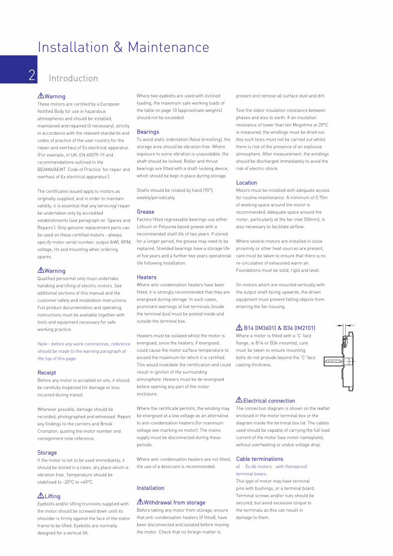
BB1144 ((IIMM33660011)) && BB3344 ((IIMM22110011))Where a motor is fitted with a ‘C’ face
flange, ie B14 or B34 mounted, care
must be taken to ensure mounting
bolts do not protude beyond the ‘C’ face
casting thickness.
EElleeccttrriiccaall ccoonnnneeccttiioonnThe connection diagram is shown on the leaflet
enclosed in the motor terminal box or the
diagram inside the terminal box lid. The cables
used should be capable of carrying the full load
current of the motor (see motor nameplate),
without overheating or undue voltage drop.
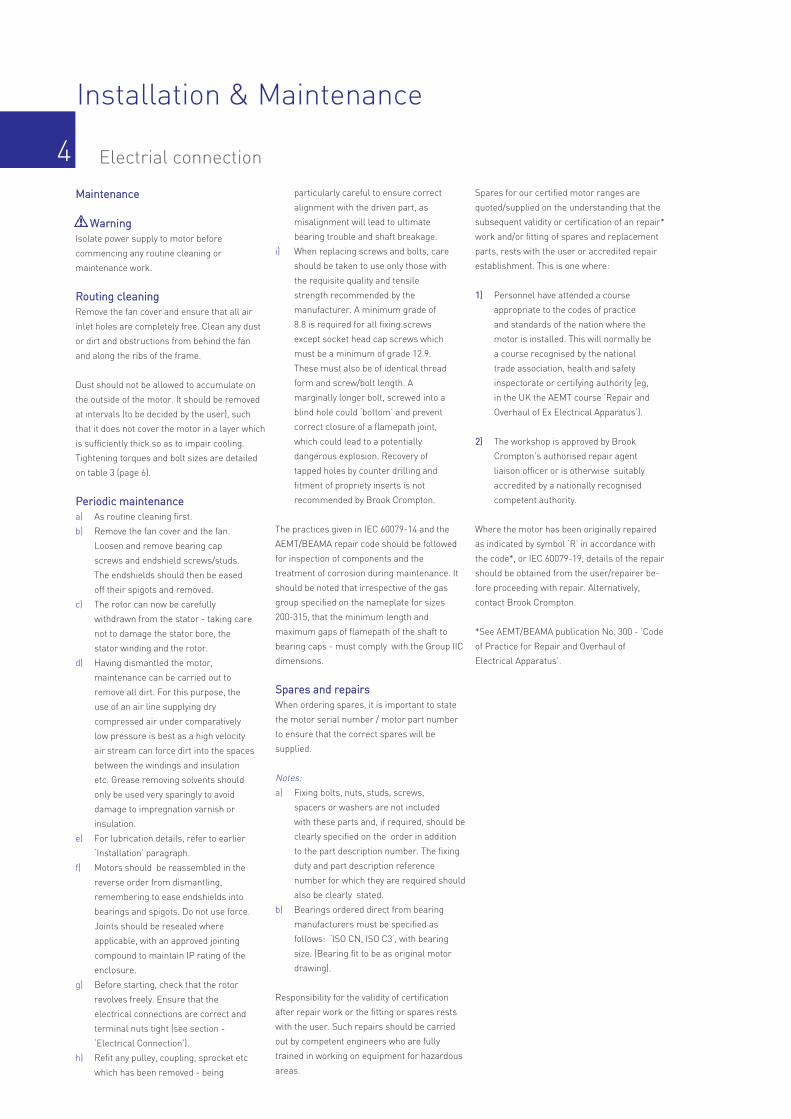
CCaabbllee tteerrmmiinnaattiioonnssa) Ex db motors - with flameproof
terminal boxes:
This type of motor may have terminal
pins with bushings, or a terminal board.
Terminal screws and/or nuts should be
secured, but avoid excessive torque to
the terminals as this can result in
damage to them.
L
LA
P N
T
L
LA
P N
T

3
Installation & Maintenance
Storage / Mechanical
b) Ex db eb motors - with increased safety
terminal boxes:
These motors are fitted with increased
safety terminals, which comprise either
slotted terminal pins, non-rotational
clamps and screw fixings or a terminal
board.
Permanently attached cables shall be suitably
protected against mechanical damage and
terminated within the terminal or junction
facility suitable for the conditions of use.
Wiring should be carried out or checked by a
qualified electrician and equipment must be
earthed in accordance with current
regulations.
When the motor is despatched with plastic
plugs fitted into the cable entry holes, these
plugs must be removed prior to commissioning
and a suitably certified gland inserted. Cable
entries are not to be left open, therefore if any
holes are unused or made redundant, they
must be plugged with a suitably certified and
correctly inserted stopping plugs (stopping
plugs to be removed only with the aid of a tool).
Alternatively, a replacement gland plate or
terminal box must be obtained from Brook
Crompton. All cable glands/conduit/plugs etc,
must have at least the same IP rating and the
hazardous area certification as the motor,
thereby ensuring that the motor certification
and protection are not compromised.
Note - the operating temperatures at the con-
duit or cable entry may exceed 70°C and at the
branching point of the conductors may exceed
80°C under rated conditions.
If aluminium cables are used they must be
terminated in such a way, as to ensure
protection against corrosion due to dissimilar
metals. Earth bonding of the motor, both on the
motor frame and inside the terminal box,
should always be carried out to eliminate the
risk of electrostatic discharges from the motor.
SSeeaalliinngg ooff tteerrmmiinnaall bbooxx aarreeaaIn order to maintain design degree of
protection:
a) Ex db motors - with flameproof
terminal boxes:
Motors are despatched with terminal
box cover and gland plate (where
required), joint faces sealing with a
non-setting joint compound. On
installation or reassembly after fitting
cables, these surfaces should be
cleaned and re-sealed using a
non- setting jointing compound.
Note - all joint faces must be undamaged and
clean prior to applying the jointing compound.
b) Ex db eb motors - with increased safety
terminal boxes:
Gaskets are fitted between terminal
facing plate and terminal box, terminal
box and lid, glandplate and box. All
gaskets must be secured to terminal
box using Bostick No.2 or equivalent
(see diagram on page 9). If a drain
plug is fitted in the box, when removed
and subsequently refitted, it must be
resealed with a suitable approved
non- setting jointing compound.
BBeeaarriinnggssBall and roller bearings are despatched from
the works fully charged with grease. Shielded
bearings have sufficient grease for an
operating life of at least two years in normal
ambient temperatures, providing there is little
or no grease leakage.
On motors with re-lubrication facilities,
replenish with a compatible grease but take
care to avoid overfilling the bearing housings. It
should be noted that over greasing presents a
far greater hazard to trouble-free service than
under greasing but careful attention is a
mandatory requirement. Bearings without
re-lubrication facilities will eventually need
replacing.
FFiittttiinngg ppiinniioonnss,, ppuulllleeyyss aanndd ccoouupplliinnggssThese should be bored to suit the shaft
diameter.
WWaarrnniinnggTapping of fitments onto the motor shaft with a
hammer or mallet, causes bearing damage.
This results in an increase in bearing noise and
a significant reduction in bearing life.
RRee--lluubbrriiccaattiioonnRecommended re-lubrication intervals are
available on request as these are load
dependant. When replenishing, use a type that
is compatible to the grease detailed on the
motor nameplate.
Note: Lithium complex type greases are not
compatible with Polyurea type greases.
FFrreeqquueennccyy ccoonnvveerrtteerrssWhen installed for use with frequency
converters, special conditions of use apply with
respect to limiting fundamental frequency,
thermal protection and surface temperatures.
Consult Brook Crompton for verification of use.
Limits of total harmonic distortion may apply.
TThheerrmmaall pprrootteeccttiioonnWhen thermal protectectors (e.g. thermistors,
thermostats) are located in the stator windings,
they must be connected to a suitable control
circuit, such that the motor is disconnected
from the mains supply at a preditermined
termperature. Failure to utilise the thermal
protection devices would invalidate the
certification.
GreaseFramesize
Type
Re-lubrication table
90 to 315
Lithiumcomplex
EssoUnirex N3
FacilityFrame size
Standard regreasing facility
Sealed for life bearingsRegrease on request
Regrease facility as standard
PolyureaNSK EA6
90 100 to180200 to 315
Installation & Maintenance
Electrial connection4MMaaiinntteennaannccee
WWaarrnniinnggIsolate power supply to motor before
commencing any routine cleaning or
maintenance work.
RRoouuttiinngg cclleeaanniinnggRemove the fan cover and ensure that all air
inlet holes are completely free. Clean any dust
or dirt and obstructions from behind the fan
and along the ribs of the frame.
Dust should not be allowed to accumulate on
the outside of the motor. It should be removed
at intervals (to be decided by the user), such
that it does not cover the motor in a layer which
is sufficiently thick so as to impair cooling.
Tightening torques and bolt sizes are detailed
on table 3 (page 6).
PPeerriiooddiicc mmaaiinntteennaanncceea) As routine cleaning first.
b) Remove the fan cover and the fan.
Loosen and remove bearing cap
screws and endshield screws/studs.
The endshields should then be eased
off their spigots and removed.
c) The rotor can now be carefully
withdrawn from the stator - taking care
not to damage the stator bore, the
stator winding and the rotor.
d) Having dismantled the motor,
maintenance can be carried out to
remove all dirt. For this purpose, the
use of an air line supplying dry
compressed air under comparatively
low pressure is best as a high velocity
air stream can force dirt into the spaces
between the windings and insulation
etc. Grease removing solvents should
only be used very sparingly to avoid
damage to impregnation varnish or
insulation.
e) For lubrication details, refer to earlier
‘Installation’ paragraph.
f) Motors should be reassembled in the
reverse order from dismantling,
remembering to ease endshields into
bearings and spigots. Do not use force.
Joints should be resealed where
applicable, with an approved jointing
compound to maintain IP rating of the
enclosure.
g) Before starting, check that the rotor
revolves freely. Ensure that the
electrical connections are correct and
terminal nuts tight (see section -
‘Electrical Connection’).
h) Refit any pulley, coupling, sprocket etc
which has been removed - being
particularly careful to ensure correct
alignment with the driven part, as
misalignment will lead to ultimate
bearing trouble and shaft breakage.
i) When replacing screws and bolts, care
should be taken to use only those with
the requisite quality and tensile
strength recommended by the
manufacturer. A minimum grade of
8.8 is required for all fixing screws
except socket head cap screws which
must be a minimum of grade 12.9.
These must also be of identical thread
form and screw/bolt length. A
marginally longer bolt, screwed into a
blind hole could ‘bottom’ and prevent
correct closure of a flamepath joint,
which could lead to a potentially
dangerous explosion. Recovery of
tapped holes by counter drilling and
fitment of propriety inserts is not
recommended by Brook Crompton.
The practices given in IEC 60079-14 and the
AEMT/BEAMA repair code should be followed
for inspection of components and the
treatment of corrosion during maintenance. It
should be noted that irrespective of the gas
group specified on the nameplate for sizes
200-315, that the minimum length and
maximum gaps of flamepath of the shaft to
bearing caps - must comply with the Group IIC
dimensions.
SSppaarreess aanndd rreeppaaiirrssWhen ordering spares, it is important to state
the motor serial number / motor part number
to ensure that the correct spares will be
supplied.
Notes:
a) Fixing bolts, nuts, studs, screws,
spacers or washers are not included
with these parts and, if required, should be
clearly specified on the order in addition
to the part description number. The fixing
duty and part description reference
number for which they are required should
also be clearly stated.
b) Bearings ordered direct from bearing
manufacturers must be specified as
follows: ‘ISO CN, ISO C3’, with bearing
size. (Bearing fit to be as original motor
drawing).
Responsibility for the validity of certification
after repair work or the fitting or spares rests
with the user. Such repairs should be carried
out by competent engineers who are fully
trained in working on equipment for hazardous
areas.
Spares for our certified motor ranges are
quoted/supplied on the understanding that the
subsequent validity or certification of an repair*
work and/or fitting of spares and replacement
parts, rests with the user or accredited repair
establishment. This is one where:
11)) Personnel have attended a course
appropriate to the codes of practice
and standards of the nation where the
motor is installed. This will normally be
a course recognised by the national
trade association, health and safety
inspectorate or certifying authority (eg,
in the UK the AEMT course ‘Repair and
Overhaul of Ex Electrical Apparatus’).
22)) The workshop is approved by Brook
Crompton’s authorised repair agent
liaison officer or is otherwise suitably
accredited by a nationally recognised
competent authority.
Where the motor has been originally repaired
as indicated by symbol ‘R’ in accordance with
the code*, or IEC 60079-19, details of the repair
should be obtained from the user/repairer be-
fore proceeding with repair. Alternatively,
contact Brook Crompton.
*See AEMT/BEAMA publication No. 300 - ‘Code
of Practice for Repair and Overhaul of
Electrical Apparatus’.

Installation & Maintenance
Electrical connection, bearings, grease, spares & repairs 5
Check that InitialInspection category*
Periodic
Table 2 – Apparatus with type of protection eb: increased safety. IEC 60079-14
Apparatus is appropriate to area classification
Surface temperature is correct
Apparatus subgroup (if any) is correct
1 Apparatus carries the correct circuit identification
Enclosures are satisfactory and undamaged
There are no unauthorised modifications
Bolts, glands and stoppers are complete and tight
2 There is no undue accumulation of dust or dirt
Earthing is satisfactory
Condition of enclosure gaskets or sealants are satisfactory
Electrical connections are tight
Motor air gaps and other running clearances are satisfactory
3 Electrical protection is satisfactory, overcurrent protection etc
There is no deterioration of encapsulating materials
Stopper boxes and cable boxes are correctly fitted
There is no leakage of compound from stopper or cable boxes
4 There is no obvious damage to cables
Apparatus is adequately protected against corrosion, the weather, vibration and other adverse factors
Guards, where used, are present and correctly fitted
Fan cowl is undamaged and fitted correctly
A
A
A
A
A
A
A
B
A
A
A
B
A
A
A
B
A
A
A
A
B
B
B
B
A
A
A
B
A
B
B
B
A
B
B
B
A
A
A
A
Check that InitialInspection category*
Periodic
Table 1 – Apparatus with type of protection db: Flameproof enclosure. IEC 60079-14
Apparatus is appropriate to area classification
Surface temperature is correct
Apparatus subgroup (if any) is correct
1 Apparatus carries the correct circuit identification
Obstructions do not conflict with IEC 60079-14
Enclosure seals are satisfactory
Gaps are free from corrosion, dirt and paint
Dimensions of gaps are correct
There are no unauthorised modifications
Bolts, glands and stoppers are complete and tight
2 There is no undue accumulation of dust or dirt
All conduit runs and fittings are tight and free from corrosion
Earthing is satisfactory
Condition of enclosure gaskets or sealants are satisfactory
Electrical connections are tight
Motor fans and couplings are not rubbing on covers/guards
3 Electrical protection is satisfactory, overcurrent protection etc
Stopper boxes and cable boxes are correctly fitted
There is no leakage of compound from stopper or cable boxes
4 There is no obvious damage to cables, cable sheaths or cable glands
Apparatus is adequately protected against corrosion, the weather, vibration and other adverse factors
Guards, where used, are present and correctly fitted
Fan cowl is undamaged and fitted correctly
A
A
A
A
A
A
A
A
A
A
B
A
A
A
A
A
A
A
B
A
A
A
A
B
B
B
B
A
A
B
B
A
A
B
B
A
B
B
A
A
B
B
A
A
A
A
NNootteess::1 Apparatus must be positively identified with
its circuit to ensure that correct isolation can be carried out.
2 Accumulation of dust or dirt can interfere with heat dissipation and result in surface temperature higher than those permitted in the hazardous area.
3 See the particular requirements for motor protection in IEC 60079-14.
4 Particular attention should be paid to flexible cables used with portable apparatus.
*Category A inspections should be carried out in allcases. Category A intervals must not exceed 2 years.More frequent and/or more detailed inspection will benecessary where there is a corrosive or other adverseatmosphere, a high risk of mechanical damage orvibration, or where there are other onerouscircumstances. The need for more frequent inspectionmay also be determined by operating experience.
The need for, the method, and the frequency ofcategory B inspections is at the discretion of theengineer responsible. It is not intended that periodicinspections should incur undue disturbance ofapparatus unless considered necessary by theengineer responsible.
Installation & Maintenance
6 Markings
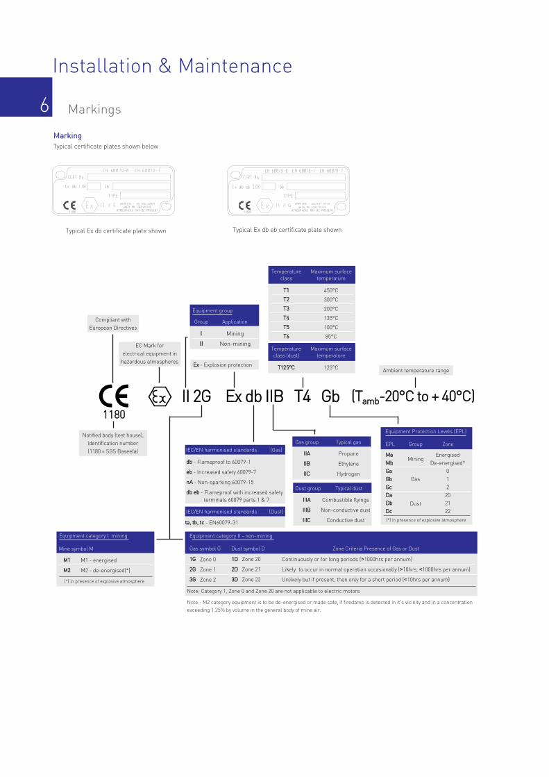
MMaarrkkiinnggTypical certificate plates shown below
Typical Ex db certificate plate shown Typical Ex db eb certificate plate shown
EC Mark forelectrical equipment in hazardous atmospheres
Notified body (test house), identification number(1180 = SGS Baseefa)
ddbb - Flameproof to 60079-1
eebb - Increased safety 60079-7
nnAA - Non-sparking 60079-15
ddbb eebb - Flameproof with increased safetyterminals 60079 parts 1 & 7
EExx - Explosion protection
Equipment group
Group
II
IIII
Mining
Non-mining
Application
Temperatureclass
TT11
TT22
TT33
TT44
TT55
TT66
450°C
300°C
200°C
135°C
100°C
85°C
Maximum surfacetemperature
Gas group
IIIIAA
IIIIBB
IIIICC
Propane
Ethylene
Hydrogen
Typical gas
IIII 22GG EExx ddbb IIIIBB TT44 GGbb11118800
Compliant withEuropean Directives
ttaa,, ttbb,, ttcc - EN60079-31
Equipment category I mining
Mine symbol M
MM11
MM22
M1 - energised
M2 - de-energised(*)
(*) in presence of explosive atmosphere
Note - M2 category equipment is to be de-energised or made safe, if firedamp is detected in it’s vicinity and in a concentrationexceeding 1.25% by volume in the general body of mine air.
IEC/EN harmonised standards (Gas)EPL
MMaaMMbbGGaaGGbbGGccDDaaDDbbDDcc
Group
Mining
Zone
(*) in presence of explosive atmosphere
Equipment Protection Levels (EPL)
Gas
Dust
EnergisedDe-energised*
012202122
Gas symbol G
11GG Zone 0
22GG Zone 1
33GG Zone 2
Dust symbol D
11DD Zone 20
22DD Zone 21
33DD Zone 22
Zone Criteria Presence of Gas or Dust
Continuously or for long periods (>1000hrs per annum)
Likely to occur in normal operation occasionally (>10hrs, <1000hrs per annum)
Unlikely but if present, then only for a short period (<10hrs per annum)
Note: Category 1, Zone 0 and Zone 20 are not applicable to electric motors
Equipment category II - non-mining
((TTaammbb--2200°°CC ttoo ++ 4400°°CC))
Ambient temperature range
Dust group
IIIIIIAA
IIIIIIBB
IIIIIICC
Combustible flyings
Non-conductive dust
Conductive dust
Typical dust
IEC/EN harmonised standards (Dust)
Temperatureclass (dust)
TT112255°°CC 125°C
Maximum surfacetemperature
Installation & Maintenance
7
II 2G Ex db IIB Baseefa02ATEX0013X
II 2G Ex db eb IIB Baseefa02ATEX0014X
II 2G Ex db IIB Baseefa02ATEX0015X
II 2G Ex db eb IIB Baseefa02ATEX0016X
II 2G Ex db IIB Baseefa02ATEX0017X
II 2G Ex db eb IIB Baseefa02ATEX0018X
II 2G Ex db IIB Baseefa02ATEX0019X
II 2G Ex db eb IIB Baseefa02ATEX0020X
II 2G Ex db IIB Baseefa02ATEX0021X
II 2G Ex db eb IIB Baseefa02ATEX0022X
II 2G Ex db IIB Baseefa02ATEX0023X
II 2G Ex db eb IIB Baseefa02ATEX0024X
II 2G Ex db IIB BAS02ATEX2111X
II 2G Ex db eb IIB BAS02ATEX2112X
II 2G Ex db eb IIC BAS02ATEX2113X
II 2G Ex db IIB BAS02ATEX2114X
II 2G Ex db eb IIB BAS02ATEX2115X
II 2G Ex db eb IIC BAS02ATEX2116X
II 2G Ex db IIB BAS02ATEX2117X
II 2G Ex db eb IIB BAS02ATEX2118X
II 2G Ex db eb IIC BAS02ATEX2119X
II 2G Ex db IIB BAS02ATEX2120X
II 2G Ex db eb IIB BAS02ATEX2121X
II 2G Ex db eb IIC BAS02ATEX2122X
II 2G Ex db IIB BAS02ATEX2123X
II 2G Ex db eb IIB BAS02ATEX2124X
II 2G Ex db eb IIC BAS02ATEX2125X
Ex db
Ex db eb
Ex db
Ex db eb
Ex db
Ex db eb
Ex db
Ex db eb
Ex db
Ex db eb
Ex db
Ex db eb
Ex db
Ex db eb
Ex db eb
Ex db
Ex db eb
Ex db eb
Ex db
Ex db eb
Ex db eb
Ex db
Ex db eb
Ex db eb
Ex db
Ex db eb
Ex db eb
W-EF90S & W-EF90L
W-EF100L
W-EF112M
W-EF132S & W-EF132M
W-EF160M & W-EF160L
W-EF180M & W-EF180L
W-EF200L & W-EF225S
W-EF225M & W-EF250S
W-EF250M & W-EF280S
W-EF280M & W-EF315S
W-EF315M & W-EF315L
IIB
IIB
IIB
IIB
IIB
IIB
IIB
IIB
IIB
IIB
IIB
IIB
IIB
IIB
IIC
IIB
IIB
IIC
IIB
IIB
IIC
IIB
IIB
IIC
IIB
IIB
IIC
BBaassiicc ffrraammeessiizzee ddeessiiggnnaattiioonn
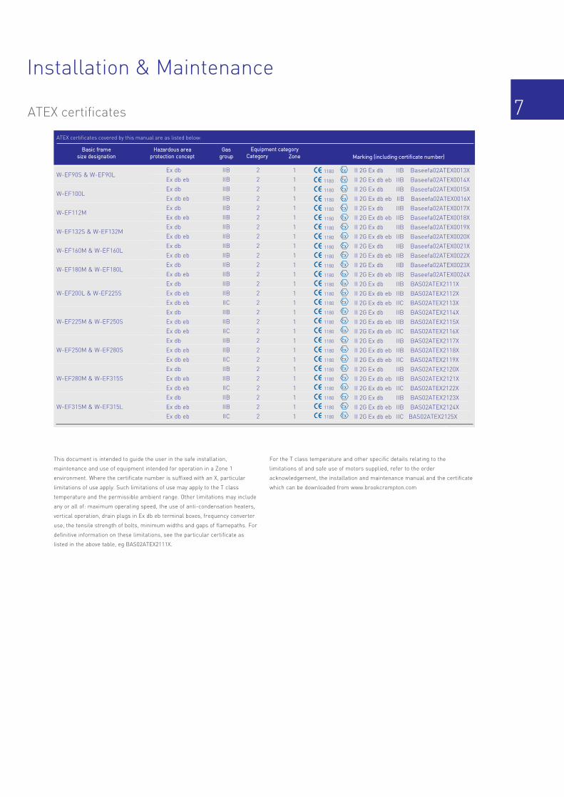
ATEX certificates covered by this manual are as listed below:
This document is intended to guide the user in the safe installation,
maintenance and use of equipment intended for operation in a Zone 1
environment. Where the certificate number is suffixed with an X, particular
limitations of use apply. Such limitations of use may apply to the T class
temperature and the permissible ambient range. Other limitations may include
any or all of: maximum operating speed, the use of anti-condensation heaters,
vertical operation, drain plugs in Ex db eb terminal boxes, frequency converter
use, the tensile strength of bolts, minimum widths and gaps of flamepaths. For
definitive information on these limitations, see the particular certificate as
listed in the above table, eg BAS02ATEX2111X.
For the T class temperature and other specific details relating to the
limitations of and safe use of motors supplied, refer to the order
acknowledgement, the installation and maintenance manual and the certificate
which can be downloaded from www.brookcrompton.com
HHaazzaarrddoouuss aarreeaapprrootteeccttiioonn ccoonncceepptt
GGaassggrroouupp CCaatteeggoorryy
2
2
2
2
2
2
2
2
2
2
2
2
2
2
2
2
2
2
2
2
2
2
2
2
2
2
2
ZZoonnee
1
1
1
1
1
1
1
1
1
1
1
1
1
1
1
1
1
1
1
1
1
1
1
1
1
1
1
EEqquuiippmmeenntt ccaatteeggoorryyMMaarrkkiinngg ((iinncclluuddiinngg cceerrttiiffiiccaattee nnuummbbeerr))
1180
1180
1180
1180
1180
1180
1180
1180
1180
1180
1180
1180
1180
1180
1180
1180
1180
1180
1180
1180
1180
1180
1180
1180
1180
1180
1180
ATEX certificates
Equipment groupGroup Application

Typical Ex db and Ex db eb motor*
Installation & Maintenance
8
1234567891011121314
RReeff PPaarrtt ddeessccrriippttiioonn
Stator frameDrive end inner bearing capDrive end bearingDrive end bearing circlipDrive end grease nippleDrive end endshieldDrive end endshield fixing screwsDrive end endshield plugDrive end bearing cap fixing screwsDrive end oilsealDrive end endshield grease plugStator foot fixing nutStator foot fixing screwStator foot
* Ex db eb motors have gaskets fitted between terminal plate and terminal box, terminal box lid andterminal box and terminal box and glandplate.See drawing of Ex db eb terminal box on page 9
The above illustration is typical only and actual machine design may vary
1
42
41
40
39
38 37
36 35
34
33
32
31
30
29
28
2
3
4
5
6
7
8
9
10
11
27
26
25
24
23
22
21
20
19
18
17
16
15
14
1312
1516171819202122232425262728
RReeff PPaarrtt ddeessccrriippttiioonn
Non-drive end inner bearing capNon-drive end bearingPreloaded washerNon-drive end endshieldNon-drive end endshield grease plugNon-drive end endshield fixing screwsNon-drive end endshield plugNon-drive end bearing cap screwsExternal fan keyExternal fanFan cover fixing flat washerFan cover fixing shakeproof washerFan cover fixing screwFan cover
2930313233343536373839404142
RReeff PPaarrtt ddeessccrriippttiioonn
External fan circlipNon-drive end grease nipple extensionNon-drive end grease nippleLifting lugLifting lug fixing screwLifting lug fixing nutExternal earth studGland plate fixing screwGland plateTerminal box lidTerminal box lid fixing screwTerminal boxTerminal plate fixing screwTerminal plate and terminals

Typical Ex db eb terminal box arrangement
Installation & Maintenance
9
2
3
4
6
2
5
7
2
1
1234567
RReeff PPaarrtt ddeessccrriippttiioonn
Terminal box cover and screwsGasket*Certified glandsGland plateIncreased safety terminalsTerminal plateTerminal box and screws
* Ex db terminal boxes do not have gaskets fitted

10
Installation & Maintenance
FFrraammee ssiizzee
Table 3 – Bolt sizes and torques
WW--UUEEFF220000LL//225500MMNNEE
WW--UUEEFF228800SSEE//331155MMEE
WW--UUEEFF331155MM && 331155LL
WW--EEFF9900SS//110000LL
WW--EEFF111122MM//113322MM
WW--EEFF116600MM//118800LL
WW--UUEEFF220000LL//225500MMEE
WW--UUEEFF2222MM//225500MMEE
WW--UUEEFF220000LL//225500MMEE
WW--UUEEFF331155MM && 331155LL
WW--EEFF9900SS//113322MM
WW--EEFF116600MM//LL
WW--EEFF118800MM//LL
WW--UUEEFF220000LL//222255SS
WW--UUEEFF222255MM//228800MMEE
WW--UUEEFF331155SSEE//331155LL
WW--UUEEFF331155SSEE//331155LL
WW--EEFF9900SS//118800LL
WW--UUEEFF220000LL//228800MMEE
WW--UUEEFF331155SSEE//331155LL
* Socket head bolts and square nuts MUST be used (Grade 12.9)** Nut
European
WW--EEFF220000LL//225500SS
WW--EEFF225500MM//331155SS
WW--EEFF331155MM && 331155LL
WW--EEFF9900SS//110000LL
WW--EEFF111122MM//113322MM
WW--EEFF116600MM//118800LL
WW--EEFF220000LL//225500SS
WW--EEFF222255MM//225500SS
WW--EEFF225500MM//331155SS
WW--EEFF331155MM && 331155LL
WW--EEFF9900SS//113322MM
WW--EEFF116600MM//LL
WW--EEFF118800MM//LL
WW--EEFF220000LL//222255SS
WW--EEFF222255MM//228800SS
WW--EEFF228800MM//331155LL
WW--EEFF228800MM//331155LL
WW--EEFF9900SS//118800LL
WW--EEFF220000LL//228800SS
WW--EEFF228800MM//331155LL
BS
All
All
All
All
All
All
All
All
All
All
All
All
All
All
All
2 pole
4 pole +
All
All
All
Poles
M10*
M16*
M20*
M6
M8
M10
M10*
M12*
M16*
M20*
M6
M8
M10
M6
M8
M8
M10
M8
M8
M10
Bolt size
52
220
400
6
16
32
52
52
220
400
6
16
32
6
16
16
31
16
16
31
Nm
Torque
Netweight kg
TTyyppee Grossweight kg
Cubagem3
WW--EEFF9900SSWW--EEFF9900LLWW--EEFF110000LLWW--EEFF111122MMWW--EEFF113322SSWW--EEFF113322MM WW--EEFF116600MMWW--EEFF116600LLWW--EEFF118800MMWW--EEFF118800LLWW--UUEEFF220000LLWW--UUEEFF222255SSWW--UUEEFF222255MMWW--UUEEFF225500MMNNEEWW--UUEEFF228800SSNNEEWW--UUEEFF228800MMNNEEWW--UUEEFF331155SSNNEEWW--UUEEFF331155MMNNEEWW--UUEEFF331155MMWW--UUEEFF331155LL
3236486486102156174224248353392452529620835950137914451645
0.050.050.650.1190.1190.1190.1610.1610.3240.3240.3240.4330.4330.8010.8311.31.31.91.92.0
303446588096144162208223325355423474580755870128413501550
WW--EEFF9900SSWW--EEFF9900LLWW--EEFF110000LLWW--EEFF111122MMWW--EEFF113322SSWW--EEFF113322MM WW--EEFF116600MMWW--EEFF116600LLWW--EEFF118800MMWW--EEFF118800LLWW--EEFF220000LLWW--EEFF222255SSWW--EEFF222255MMWW--EEFF225500SSWW--EEFF225500MMWW--EEFF228800SSWW--EEFF228800MMWW--EEFF331155SSWW--EEFF331155MMWW--EEFF331155LL
European BS
Location
Foot and
lifting lugs
Flange and
endshield
Bearing
cap
Gland plate and
terminal box lid
Bolt sizes and torques
Approximate shipping specifications
Terminal nut torque
M5
M6
M8
M8
M8
M10
M8
M10
M12
Frame size
2.2
3.8
9.3
9.3
9.3
12
9.3
12
15
Terminalnut
Torque(Nm)
1.6
2.8
6.8
6.8
6.8
8.9
6.8
8.9
11
Torque(lb-ft)
90 to 112
132 to 160
180
200 to 250S
250M to 315S
315M / L

11
Installation & Maintenance
WW--UUEEFF220000LLNN
WW--UUEEFF222255SS
WW--UUEEFF222255MM
WW--UUEEFF225500MMEE ((22PP))
WW--UUEEFF225500MMEE
WW--UUEEFF228800SSEE ((22PP))
WW--UUEEFF228800SSEE
WW--UUEEFF228800MMEE ((22PP))
WW--UUEEFF228800MMEE
WW--UUEEFF331155SSEE ((22PP))
WW--UUEEFF331155SSEE
WW--UUEEFF331155MMEE ((22PP))
WW--UUEEFF331155MMEE
WW--UUEEFF331155MM//LL ((22PP))
WW--UUEEFF331155MM//LL
RReelluubbrriiccaattiioonn iinntteerrvvaallss oonn aa 5500HHzz ssuuppppllyy xx 1100 33 hhoouurrss -- GGrreeaassee ttyyppee:: EEssssoo UUnniirreexx
European
WW--EEFF220000LLNN
WW--EEFF222255SS
WW--EEFF222255MM
WW--EEFF225500SS ((22PP))
WW--EEFF225500SS
WW--EEFF225500MM ((22PP))
WW--EEFF225500MM
WW--EEFF228800SS ((22PP))
WW--EEFF228800SS
WW--EEFF228800MM ((22PP))
WW--EEFF228800MM
WW--EEFF331155SS ((22PP))
WW--EEFF331155SS
WW--EEFF331155MM//LL ((22PP))
WW--EEFF331155MM//LL
BS
12.6
12.6
11.3
12.6
-
11.3
-
11.3
-
9.4
-
9.4
-
9.4
-
Horizontal
3000 min-1
Vertical Horizontal
8.2
8.2
7.4
8.2
-
7.4
-
7.4
-
6.1
-
6.1
-
6.1
-
30.0
30.0
29.5
-
26.3
-
23.4
-
23.4
-
21.3
-
21.3
-
21.3
20.3
20.3
19.2
-
17.1
-
15.2
-
15.2
-
13.8
-
13.8
-
13.8
30.0
30.0
30.0
-
30.0
-
30.0
-
30.0
-
30.0
-
30.0
-
30.0((22PP)) = 2 pole motor
27.8
27.8
26.0
-
23.6
-
21.3
-
21.3
-
20.3
-
20.3
-
20.3
30.0
30.0
30.0
-
30.0
-
30.0
-
30.0
-
30.0
-
30.0
-
30.0
30.0
30.0
30.0
-
29.3
-
27.8
-
27.8
-
26.0
-
26.0
-
26.0
Vertical Horizontal Vertical Horizontal Vertical
1500 min-1 1000 min-1 750 min-1MMoottoorr TTyyppee
6313
6313
6314
6314
6316
6314
6318
6314
6318
6316
6319
6316
6319
6316
6319
DEBearing
NDEBearing
Greaseqty (gms)
6313
6313
6314
6314
6316
6314
6318
6314
6318
6316
6319
6316
6319
6316
6319
23
23
26
26
33
26
41
26
41
33
45
33
45
33
45
WW--UUEEFF220000LLNN
WW--UUEEFF222255SS
WW--UUEEFF222255MM
WW--UUEEFF225500MMEE ((22PP))
WW--UUEEFF225500MMEE
WW--UUEEFF228800SSEE ((22PP))
WW--UUEEFF228800SSEE
WW--UUEEFF228800MMEE ((22PP))
WW--UUEEFF228800MMEE
WW--UUEEFF331155SSEE ((22PP))
WW--UUEEFF331155SSEE
WW--UUEEFF331155MMEE ((22PP))
WW--UUEEFF331155MMEE
WW--UUEEFF331155MM//LL ((22PP))
WW--UUEEFF331155MM//LL
RReelluubbrriiccaattiioonn iinntteerrvvaallss oonn aa 6600HHzz ssuuppppllyy xx 1100 33 hhoouurrss -- GGrreeaassee ttyyppee:: EEssssoo UUnniirreexx
European
WW--EEFF220000LLNN
WW--EEFF222255SS
WW--EEFF222255MM
WW--EEFF225500SS ((22PP))
WW--EEFF225500SS
WW--EEFF225500MM ((22PP))
WW--EEFF225500MM
WW--EEFF228800SS ((22PP))
WW--EEFF228800SS
WW--EEFF228800MM ((22PP))
WW--EEFF228800MM
WW--EEFF331155SS ((22PP))
WW--EEFF331155SS
WW--EEFF331155MM//LL ((22PP))
WW--EEFF331155MM//LL
BS
8.0
8.0
7.5
7.5
-
7.5
-
7.5
-
5.3
-
5.3
-
5.3
-
Horizontal
3600 min-1
Vertical Horizontal
5.2
5.2
4.9
4.9
-
4.9
-
4.9
-
3.4
-
3.4
-
3.4
-
26.3
26.3
25.0
-
22.0
-
17.5
-
17.5
-
16.3
-
16.3
-
16.3
17.1
17.1
16.3
-
14.3
-
11.4
-
11.4
-
10.6
-
10.6
-
10.6
30.0
30.0
30.0
-
30.0
-
29.0
-
29.0
-
27.5
-
27.5
-
27.5((22PP)) = 2 pole motor
24.4
24.4
22.8
-
21.1
-
18.9
-
18.9
-
17.9
-
17.9
-
17.9
30.0
30.0
30.0
-
30.0
-
30.0
-
30.0
-
30.0
-
30.0
-
30.0
29.3
29.3
27.6
-
25.7
-
24.1
-
24.1
-
22.8
-
22.8
-
22.8
Vertical Horizontal Vertical Horizontal Vertical
1800 min-1 1200 min-1 900 min-1MMoottoorr TTyyppee
6313
6313
6314
6314
6316
6314
6318
6314
6318
6316
6319
6316
6319
6316
6319
DEbearing
NDEbearing
greaseqty (gms)
6313
6313
6314
6314
6316
6314
6318
6314
6318
6316
6319
6316
6319
6316
6319
23
23
26
26
33
26
41
26
41
33
45
33
45
33
45
Bearing grease and re-lubrication intervals
Bearings are pre-packed with a grease type
dependant on frame size.
Generally standard motors frame sizes 90 to
180 are sealed for life bearings.
Sealed for life bearings can be identified on the
motor name plate with ‘ZZ’ or ‘2Z’ appearing
after the bearing size for example 6310ZZ.
Motor frames sizes 132 to 180 could have an
option to include re-lubrication facilities.
To quote re-lubrication intervals for these
frame sizes please contact the sales office,
quoting either a part number or motor serial
number from the motor nameplate.
Motor frame sizes 200 to 315 are supplied with
re-lubrication facilities, the re-lubrication
intervals are shown in the tables below.
Regreasing intervals
The data quoted in the tables above is based on 70°C. These intervals should be halved for every 15°C above 70°C.

Brook Crompton UK LtdSt Thomas’ Road HuddersfieldWest Yorkshire HD1 3LJ UKTel: +44 (0) 1484 557200Fax: +44 (0) 1484 557201E-mail: [email protected]: www.brookcrompton.com
dh1113/**/*/08/16 2217E Iss 4 (Ex db/eb I&M)© Copyright. Brook Crompton UK Ltd. All rights reserved.
Every care has been taken to ensure the accuracy of the
information contained in this publication, but, due to a policy of
continuous development and improvement the right is reserved
to supply products which may differ slightly from those
illustrated and described in this publication
Recommended