2D Code ReaderV400-F
Created to meet real-world production site needs.
For Easier, More Accurate Quality Contr
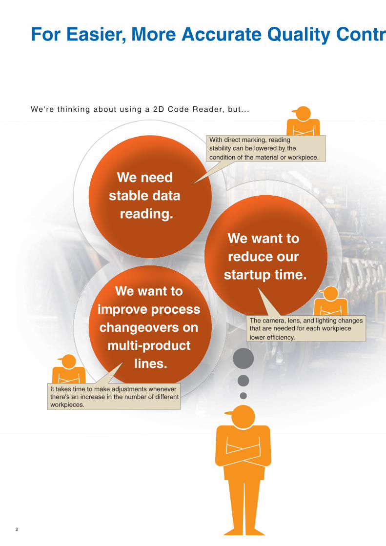
We want to reduce our
startup time.We want to
improve process changeovers on
multi-product lines.
We need stable data
reading.
2
We're th inking about using a 2D Code Reader, but . . .
With direct marking, reading stability can be lowered by the condition of the material or workpiece.
It takes time to make adjustments whenever there's an increase in the number of different workpieces.
The camera, lens, and lighting changes that are needed for each workpiece lower efficiency.

ol
3
OMRON created
the 2D Code Reader
to meet needs l ike these.
Actual Size
In the V400-F, we have l is tened careful ly to user demands
and worked hard to achieve high levels of s impl ic i ty and
rel iabi l i ty in a code reader that v i r tual ly anybody can instal l ,
operate, and adjust .
We also pursued highly accurate reading of d i rect ly marked
2D codes, in addi t ion to pr inted codes.
The V400-F is a new 2D Code Reader that makes product ion
s i tes considerably "smar ter" in a wide range of environments.
4
Simplicity and High Performance in Response to User Needs
Simplif ied Setup.. .
Banks.. .
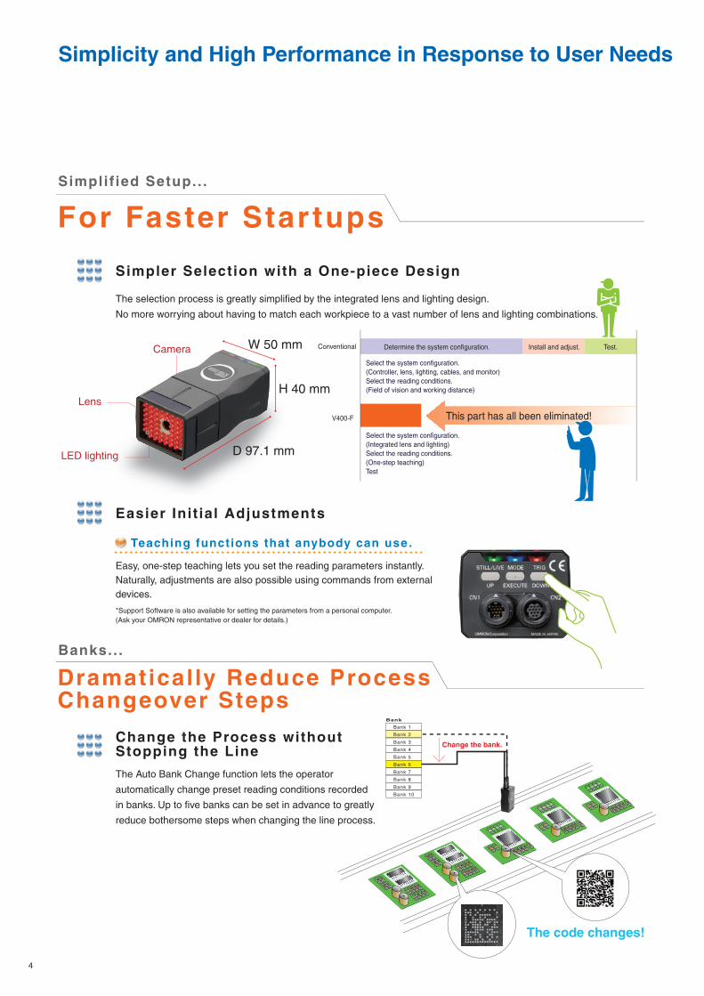
Easy, one-step teaching lets you set the reading parameters instantly. Naturally, adjustments are also possible using commands from external devices.
*Support Software is also available for setting the parameters from a personal computer. (Ask your OMRON representative or dealer for details.)
Teaching functions that anybody can use.
For Faster Star tups
Dramatically Reduce Process Changeover Steps
Simpler Selection with a One-piece Design
The selection process is greatly simplified by the integrated lens and lighting design.
No more worrying about having to match each workpiece to a vast number of lens and lighting combinations.
Easier Init ial Adjustments
The Auto Bank Change function lets the operator
automatically change preset reading conditions recorded
in banks. Up to five banks can be set in advance to greatly
reduce bothersome steps when changing the line process.
Change the Process without Stopping the Line
Bank
Bank 1
Bank 2
Bank 3
Bank 4
Bank 5
Bank 6
Bank 7
Bank 8
Bank 9
Bank 10
Change the bank.
Conventional
V400-F
Determine the system configuration. Install and adjust.
Select the system configuration.(Controller, lens, lighting, cables, and monitor)Select the reading conditions.(Field of vision and working distance)
Select the system configuration.(Integrated lens and lighting)Select the reading conditions.(One-step teaching)Test
Test.W 50 mm
H 40 mm
D 97.1 mm
Camera
Lens
LED lighting
This part has all been eliminated!
The code changes!
5
For Stable ReadingHigh Performance.. .
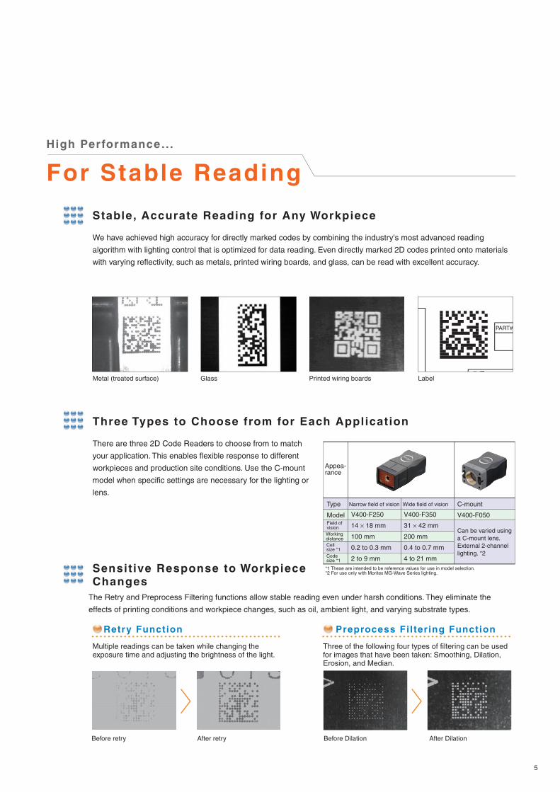
Stable, Accurate Reading for Any Workpiece
We have achieved high accuracy for directly marked codes by combining the industry's most advanced reading
algorithm with lighting control that is optimized for data reading. Even directly marked 2D codes printed onto materials
with varying reflectivity, such as metals, printed wiring boards, and glass, can be read with excellent accuracy.
Three Types to Choose from for Each Application
There are three 2D Code Readers to choose from to match
your application. This enables flexible response to different
workpieces and production site conditions. Use the C-mount
model when specific settings are necessary for the lighting or
lens.
The Retry and Preprocess Filtering functions allow stable reading even under harsh conditions. They eliminate the
effects of printing conditions and workpiece changes, such as oil, ambient light, and varying substrate types.
Sensit ive Response to Workpiece Changes
Retry Function
PART#
Before retry
Metal (treated surface) Glass Printed wiring boards Label
After retry
Preprocess Filtering Function
Before Dilation After Dilation
Type
ModelField of visionWorking distance
Appea-rance
C-mount
V400-F050
Multiple readings can be taken while changing the exposure time and adjusting the brightness of the light.
Three of the following four types of filtering can be used for images that have been taken: Smoothing, Dilation, Erosion, and Median.
Cell size *1Code size *1
*1 These are intended to be reference values for use in model selection.*2 For use only with Moritex MG-Wave Series lighting.
Narrow field of vision Wide field of vision
V400-F250
14 × 18 mm
100 mm
0.2 to 0.3 mm
2 to 9 mm
V400-F350
31 × 42 mm
200 mm
0.4 to 0.7 mm
4 to 21 mm
Can be varied using a C-mount lens.External 2-channel lighting. *2

6
Applications
System Configuration
V400-F050
V400-F250/350
Moritex MG-Wave Series recommended.
C mount
V400-W23/23P*
SYSMAC Series PLC
Personal computer(Connected to the RC-232C port)
5 m
5 m
Monitor
Recommended power supply: OMRON S8VS-03024
*Use only the specified cable.
Power Supply
Power Supply
V400-W24/24P*
5 m
Metal parts Printed wiring boards LCD glass substrates Trading partner labels
External Lighting Connector
Lens
Lighting
Monitor CableV400-WM0*
Ordering Information
Name Model Field of vision
Special Lighting LensV400-F250 14 ´ 18 mm
V400-F350
C-Mount V400-F050 Changes according to the lens.
Accessories (Order Separately) and Cables
2D Code Readers
31 ´ 42 mm
Communications Cable
Monitor Cable
V400-W23 5M (NPN)
V400-W23P 5M (PNP)
V400-W24 5M (NPN)
V400-W24P 5M (PNP)
V400-WM0 5M
5 m
5 m
For connection to an IBM PC/AT or
compatible (includes power line)
For connection to SYSMAC Series
PLC (includes power line)
Name Model Cable length Remarks
The CS1W-CIF31 USB-Serial Conversion Cable (mfd. by OMRON) is recommended for connection to a USB terminal.

7
Specifications
Dimensions
25.4
442015
844
25.4
35.2
31.6
Two M4
holes
Two M2, depth: 5
1/4-20UNC
Four 3.4-dia holes
Four 5.4-dia. countersunk holes, depth: 2.2
50
39.8500
5020
5000
D-sub 9-pinconnector
50
(13.
1)
(16.8)25.4
75.3(84.1)
26.8
1.6
25.4
40
11.5 dia.Lighting connector(L-CH)
1"-32UN-2A(C mount)
Power supply, communications connector
Monitor cable connector
Four M3, depth: 5
50
40
(105.9)97.1
48.6 25.4
25.4
(13.
1)
(16.8)
7060
40
15010
39.8 5000
12.2
dia
.
RCA jack12-pin round connector
NameplateVinyl-insulated round cable, 6.5-dia. with 3 conductors
15.5
dia
.
V400-F050 V400-W23/23P/24/24P
V400-WM0
2D Code Readers Communications Cable and Monitor Cable
V400-F250/350
Mounting Base
Nameplate
Vinyl-insulated round cable, 7.0-dia. with 12 conductors
15.5
dia
.
12-pin round connector
11.5 dia.
Lighting connector(R-CH)
Four M3, depth: 5
Power supply, communications connector
Monitor cable connector
11.5 dia. 11.5 dia.
(Unit: mm)
Model V400-F050
40 ´ 50 ´ 75.3 mm
Depends on the lens.
Depends on the lens.Up to two can be directly powered.
V400-F250 V400-F350
Approx. 100 mm
Approx. 14 ´ 18 mm
Red LED
Approx. 200 mm
Approx. 31 ´ 42 mm
NoneApprox. 130 g
IEC 60529 IP67Approx. 150 gWeight
Degree of protection
Ambient environmentAmbient temperatureAmbient humidityShock resistance
Vibration resistance
Applicable standards
Noise resistance
Leakage currentWithstand voltage
Insulation resistance
Power consumption
Power supply voltage
Effective pixels
Image sensor
Lighting
Applicable codes
Field of vision
Working distance (WD)
Dimensions
Data Matrix, ECC200, 10 ´ 10 to 64 ´ 64, 8 ´ 18 to 16 ´ 48,
QR Code (Models 1, 2), 21 ´ 21 to 57 ´ 57 (Versions 1 to 10)
Power line: 2 kVp-p, Pulse width: 50 ns, Rise time: 5 ns, Consecutive burst time: 15 ms, Cycle: 300 ms
CE: EN 61326:1997, +A1:1998, +A2:2001 (EMI: Class A)
10 to 150 Hz, 0.35-mm half-amplitude (maximum acceleration: 50 m/s2) 10 times for 8 minutes each in 3 directions
40 ´ 50 ´ 97.1 mm

A Handy, LCD-equipped 2D Code Reader Capable of Reading Directly Marked CodesV400-H111/211
Refer to the catalog for details (Cat. No. Q146).
Model with Narrow Field of Vision (V400-H111): 5- to 10-mm field of visionModel with Wide Field of Vision (V400-H211): 15- to 30-mm field of vision
Applications:
The V400-H achieves a high level of accuracy by combining the industry's most advanced reading algorithm with an optical system that is optimized for reading directly marked codes.
Use the LCD monitor to check the codes as you read them. The information that is read is displayed on the screen, facilitating confirming operation.
Reading codes on metal parts, LCD wafers, printed wiring board substrates
Excellent
reading
performance
Read while
viewing
the LCD
This document provides information mainly for selecting suitable models. Please read the Z242 carefully for information that the user must understand and accept before purchase, including information on warranty, limitations of liability, and precautions.
Note: Do not use this document to operate the Unit.
Authorized Distributor:
In the interest of product improvement, specifications are subject to change without notice.
OMRON Industrial Automation Global: www.ia.omron.com
OMRON CorporationIndustrial Automation Company
Regional HeadquartersOMRON EUROPE B.V.Sensor Business UnitCarl-Benz-Str. 4, D-71154 Nufringen,GermanyTel: (49) 7032-811-0/Fax: (49) 7032-811-199
OMRON ELECTRONICS LLCOne Commerce Drive Schaumburg, IL 60173-5302 U.S.A.Tel: (1) 847-843-7900/Fax: (1) 847-843-7787
OMRON ASIA PACIFIC PTE. LTD.No. 438A Alexandra Road # 05-05/08 (Lobby 2), Alexandra Technopark, Singapore 119967Tel: (65) 6835-3011/Fax: (65) 6835-2711
OMRON (CHINA) CO., LTD.Room 2211, Bank of China Tower, 200 Yin Cheng Zhong Road, PuDong New Area, Shanghai, 200120, ChinaTel: (86) 21-5037-2222/Fax: (86) 21-5037-2200
Sensing Devices Division H.Q.Application Sensors DivisionShiokoji Horikawa, Shimogyo-ku,Kyoto, 600-8530 JapanTel: (81) 75-344-7068/Fax: (81) 75-344-7107
CSM_1_4_0216Cat. No. Q148-E1 Printed in Japan
Recommended