Removal and Reassembly _ 9
3. DISASSEMBLY AND REASSEMBLY
3-1. TOOLS FOR DISASSEMBLY AND REASSEMBLY
Tool Type Remarks
SocketWrenchwith6”Extension
10mm13mm19mm
Heater(1)Motor(1),Balance(5),2holesofeachleftandrightoftheshockabsorber1Pulleyhole
OpenEndwrench
10mm13mm19mm
Replaceablefortheboxdriver.Sincetheboltrunsidlewhentheboxdriverisused,usetheboxdriver17mm.
Vicepliers Tooltoprotecttheidleandabrasionoftheboltfortheboxdriver.
Others(Driver,Nipper,Longnose)
Generaltoolsfortheafterservice.
10 _ Removal and Reassembly
3-2. STANDARD DISASSEMBLY DRAWINGS▶ Thisisastandarddisassemblydiagramandmaydifferfromtheactualproduct.
Usethismaterialasareferencewhendisassemblingandreassemblingtheproduct.
Part Figure Description
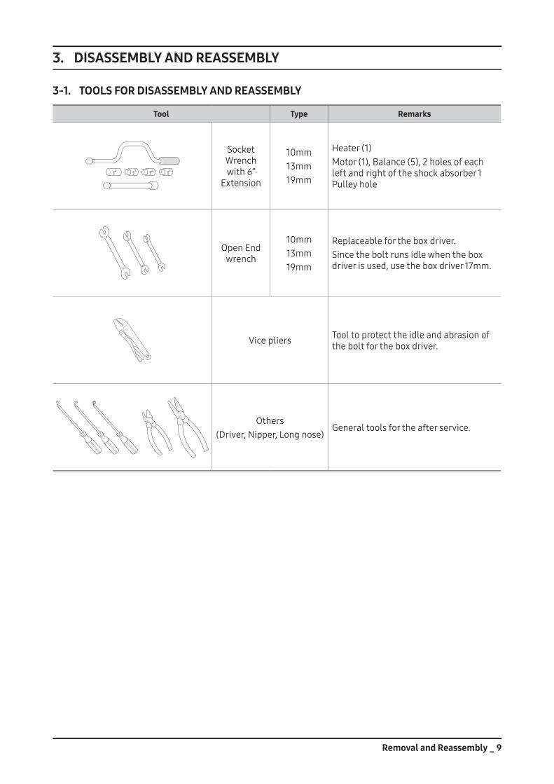
Disassembling and Repairing the Rear Motor
1. Removethe2screwsholdingtheBack-CoveratthebackofthewashingmachineandseparatetheBack-Coverpushingitdownwards.(Assembleitbyliftingitupwards)
2. AfterseparatingtheBack-Cover,removetheM19nutholdingtheMotor.Toremoveit,turnitcounter-clockwise.AstheMotoralsorotatesifthenutisturnedslowly,torqueitquicklyandfirmlyinasingleaction.
DonotremovethenutbyinsertingascrewdriverintotheMotor,asthismayresultinaproblemwiththemotor.
3. RemovetheM19nutandwasherandthenseparatetheRotor.SinceremovingtherotorrequiresalotofstrengthduetothemagneticforceoftheRotoranditmaycomeoffsuddenly,yourhandorarmmaybeinjuredbytheedgeoftheStatororFrame.Thereforetakeprecautionwhenseparatingit.
Youcanseparatetheconnectorbypressing
Motorwire
Hallsensor4. SeparatetheMotorWireandHallSensor
whilepressingthenaveloftheHousing.TakeprecautionwhenyoudothisbecausetheHallSensorpartiseasilyshocked.
5. Separatethe6M10screws.→SeparatetheAssyBracketMotor→SeparatetheStator. Whenremovingthelastofthe6screws,holdtheStatorasitmayfallwhenthescrewsareremoved.
* Check Points for Troubleshooting1. CheckifthereisanyaliensubstancebetweentheRotorandtheStator.2. Checkifthemotorpower(Blue,White,Red)wireisconnected.3. CheckiftheHallSensorwireisconnected.
TheorderofthemotorwiresisBlue,White,andRedfromtheright.CheckiftheresistancebetweenBlue-White,White-Red,andRed-Blueisequalto15Ω.
Reassemblyisinthereverseorderoftheremoval.
Removal and Reassembly _ 11
Part Figure Description
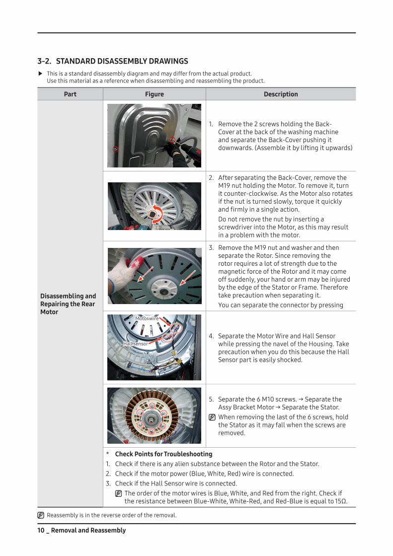
Disassembling and Repairing the Thermistor
1. SeparatetheAssyThermistorandGuideWire-TwhilepullingtheAssyThermistor.
2. SeparatetheAssyThermistorandAssyWireHarnesswhilepressingthenaveloftheHousing.
3. PulltheAssyThermistorfromTubBack.WhendisassemblingAssyThermistor,leave
therubberpacking.
CAUTION
OK NG
OK NGGap
1. WhenassemblingAssyThermistor,pushtotheend.IfassemblinglikeNGpicture,waterleakagepossibilityishigh.
2. WhenassemblinganddisassemblingAssyThermistor,rubberPackingshouldbechecked.Ifthegapexistedbetweenrubberpackingandtub-back,waterleakagepossibilityishigh.
12 _ Removal and Reassembly
Part Figure Description
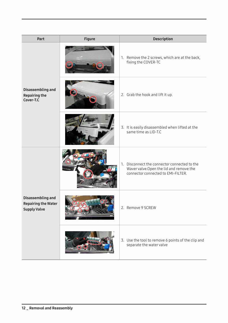
Disassembling andRepairing the Cover-T.C
1. Removethe2screws,whichareattheback,fixingtheCOVER-TC
2. Grabthehookandliftitup.
3. Itiseasilydisassembledwhenliftedatthesame time as LID-T.C
Disassembling andRepairing the WaterSupply Valve
1. DisconnecttheconnectorconnectedtotheWavervalve.OpenthelidandremovetheconnectorconnectedtoEMI-FILTER.
2. Remove 9 SCREW
3. Usethetooltoremove6pointsoftheclipandseparatethewatervalve
Removal and Reassembly _ 13
Part Figure Description
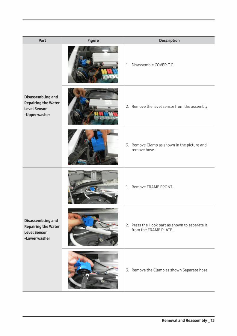
Disassembling andRepairing the WaterLevel Sensor-Upper washer
1. DisassembleCOVER-T.C.
2. Removethelevelsensorfromtheassembly.
3. RemoveClampasshowninthepictureandremovehose.
Disassembling andRepairing the WaterLevel Sensor-Lower washer
1. Remove FRAME FRONT.
2. PresstheHookpartasshowntoseparateItfromtheFRAMEPLATE.
3. RemovetheClampasshownSeparatehose.
14 _ Removal and Reassembly
Part Figure Description
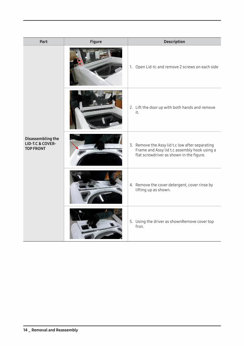
Disassembling the LID-T.C & COVER-TOP FRONT
1. OpenLid-tcandremove2screwsoneachside
2. Liftthedoorupwithbothhandsandremoveit.
3. RemovetheAssylidt.clowafterseparatingFrameandAssylidt.cassemblyhookusingaflatscrewdriverasshowninthefigure.
4. Removethecoverdetergent,coverrinsebyliftingupasshown.
5. UsingthedriverasshownRemovecovertopfron.
Removal and Reassembly _ 15
Part Figure Description
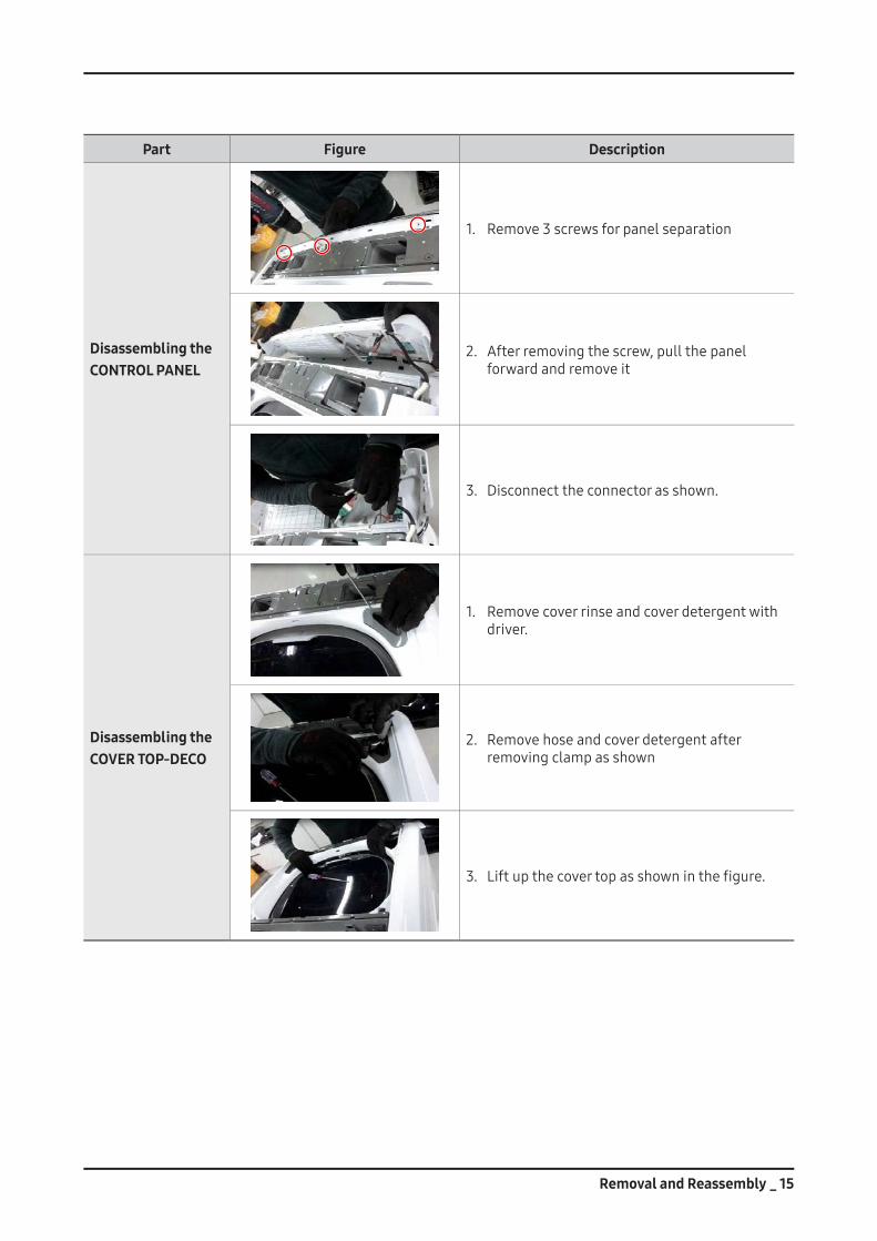
Disassembling the CONTROL PANEL
1. Remove3screwsforpanelseparation
2. Afterremovingthescrew,pullthepanelforwardandremoveit
3. Disconnecttheconnectorasshown.
Disassembling the COVER TOP-DECO
1. Removecoverrinseandcoverdetergentwithdriver.
2. Removehoseandcoverdetergentafterremovingclampasshown
3. Liftupthecovertopasshowninthefigure.
16 _ Removal and Reassembly
Part Figure Description
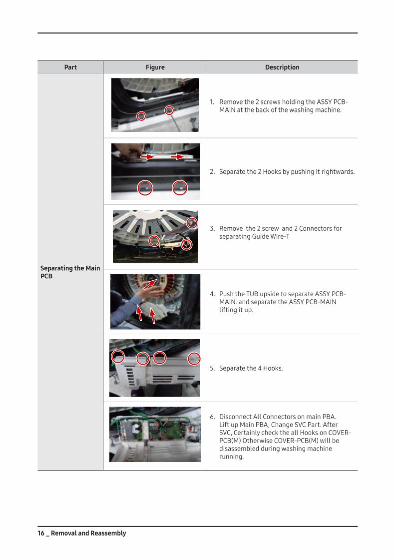
Separating the Main PCB
1. Removethe2screwsholdingtheASSYPCB-MAINatthebackofthewashingmachine.
2. Separatethe2Hooksbypushingitrightwards.
3. Removethe2screwand2ConnectorsforseparatingGuideWire-T
4. PushtheTUBupsidetoseparateASSYPCB-MAIN.andseparatetheASSYPCB-MAINliftingitup.
5. Separatethe4Hooks.
6. DisconnectAllConnectorsonmainPBA. LiftupMainPBA,ChangeSVCPart.AfterSVC,CertainlychecktheallHooksonCOVER-PCB(M)OtherwiseCOVER-PCB(M)willbedisassembledduringwashingmachinerunning.
Removal and Reassembly _ 17
Part Figure Description
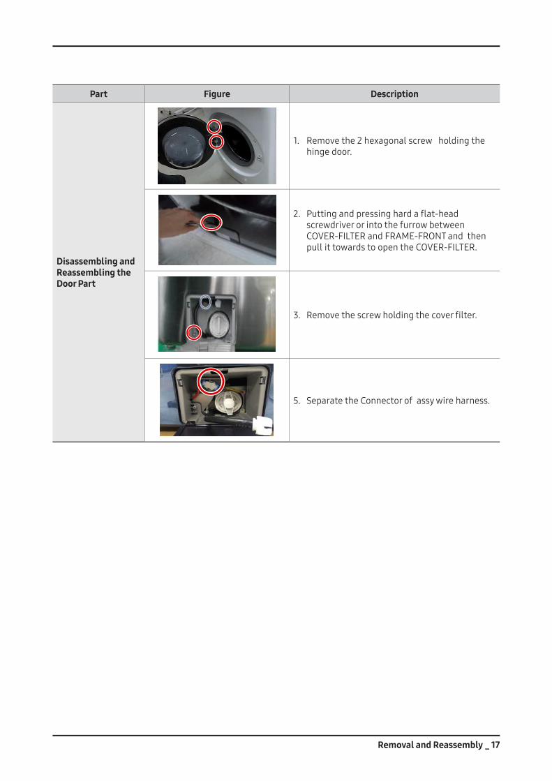
Disassembling and Reassembling the Door Part
1. Removethe2hexagonalscrewholdingthehingedoor.
2. Puttingandpressinghardaflat-headscrewdriverorintothefurrowbetweenCOVER-FILTERandFRAME-FRONTandthenpullittowardstoopentheCOVER-FILTER.
3. Removethescrewholdingthecoverfilter.
5. SeparatetheConnectorofassywireharness.
18 _ Removal and Reassembly
Part Figure Description
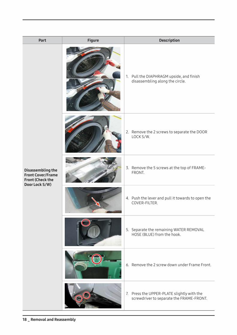
Disassembling the Front Cover/Frame Front (Check the Door Lock S/W)
1. PulltheDIAPHRAGMupside,andfinishdisassemblingalongthecircle.
2. Removethe2screwstoseparatetheDOORLOCKS/W.
3. Removethe5screwsatthetopofFRAME-FRONT.
4. PushtheleverandpullittowardstoopentheCOVER-FILTER.
5. SeparatetheremainingWATERREMOVALHOSE(BLUE)fromthehook.
6. Removethe2screwdownunderFrameFront.
7. PresstheUPPER-PLATEslightlywiththescrewdrivertoseparatetheFRAME-FRONT.
Removal and Reassembly _ 19
Part Figure Description
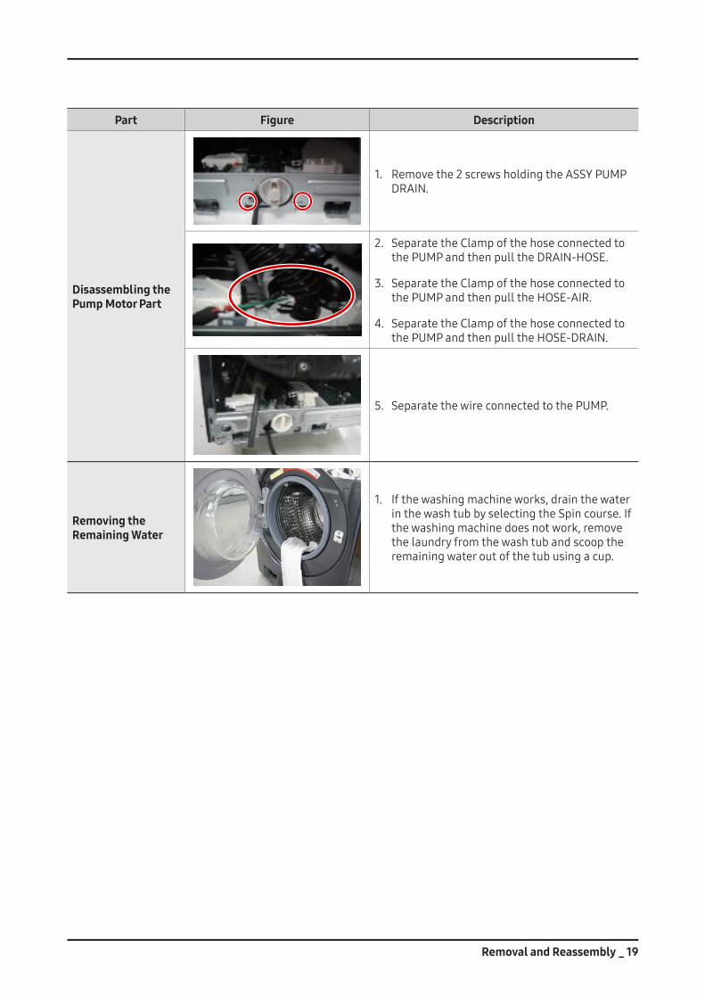
Disassembling the Pump Motor Part
1. Removethe2screwsholdingtheASSYPUMPDRAIN.
2. SeparatetheClampofthehoseconnectedtothePUMPandthenpulltheDRAIN-HOSE.
3. SeparatetheClampofthehoseconnectedtothePUMPandthenpulltheHOSE-AIR.
4. SeparatetheClampofthehoseconnectedtothePUMPandthenpulltheHOSE-DRAIN.
5. SeparatethewireconnectedtothePUMP.
Removing the Remaining Water
1. Ifthewashingmachineworks,drainthewaterinthewashtubbyselectingtheSpincourse.Ifthewashingmachinedoesnotwork,removethelaundryfromthewashtubandscooptheremainingwateroutofthetubusingacup.
20 _ Removal and Reassembly
Part Figure Description
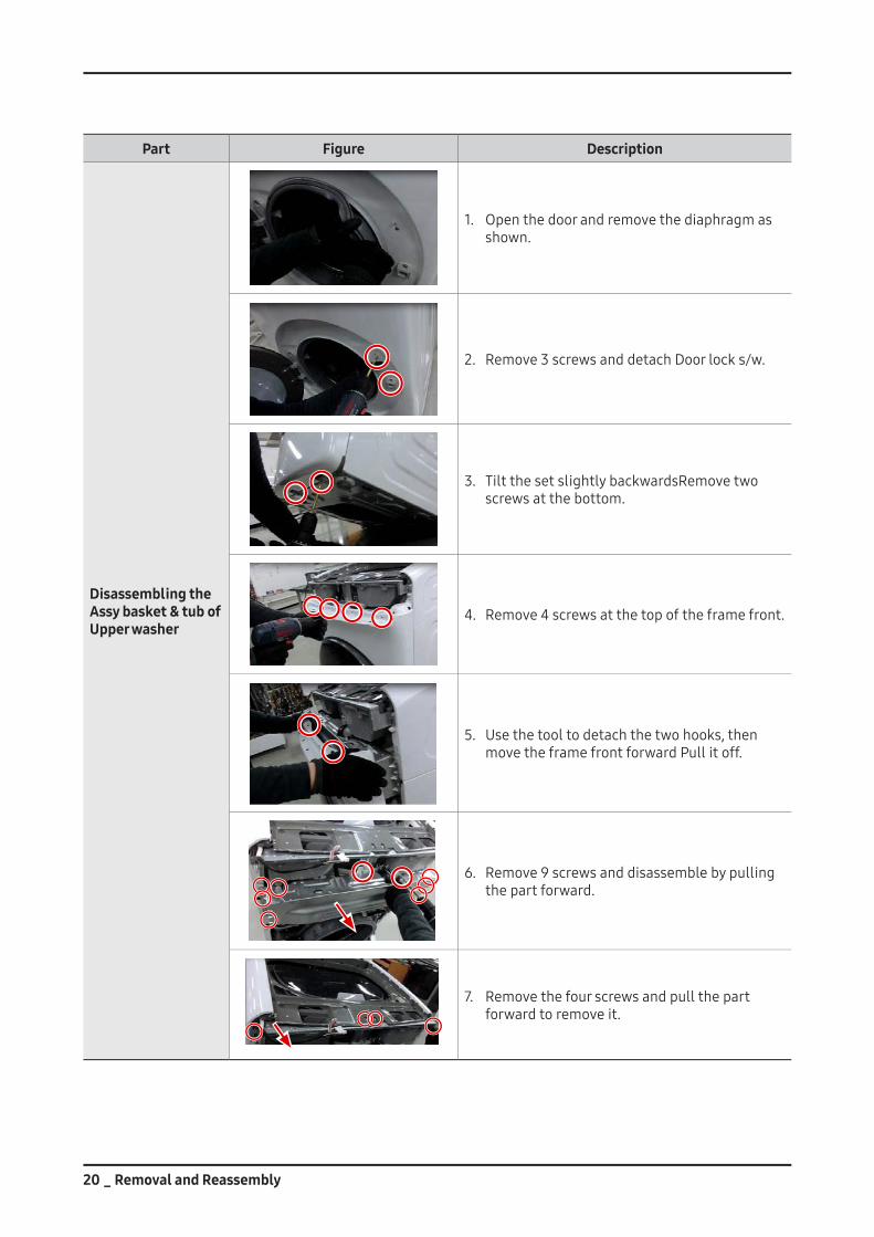
Disassembling the Assy basket & tub of Upper washer
1. Openthedoorandremovethediaphragmasshown.
2. Remove3screwsanddetachDoorlocks/w.
3. TiltthesetslightlybackwardsRemovetwoscrewsatthebottom.
4. Remove4screwsatthetopoftheframefront.
5. Usethetooltodetachthetwohooks,thenmovetheframefrontforwardPullitoff.
6. Remove9screwsanddisassemblebypullingthepartforward.
7. Removethefourscrewsandpullthepartforwardtoremoveit.
Removal and Reassembly _ 21
Part Figure Description
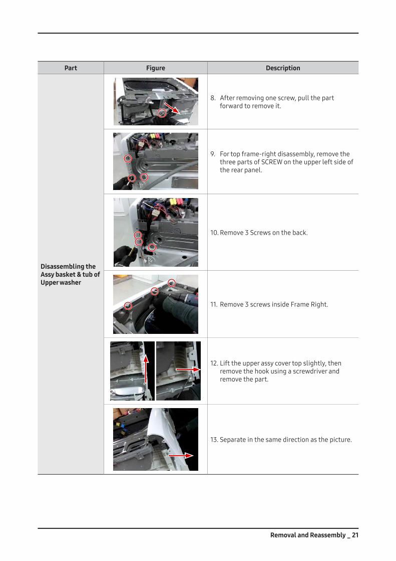
Disassembling the Assy basket & tub of Upper washer
8. Afterremovingonescrew,pullthepartforwardtoremoveit.
9. Fortopframe-rightdisassembly,removethethreepartsofSCREWontheupperleftsideoftherearpanel.
10.Remove3Screwsontheback.
11.Remove3screwsinsideFrameRight.
12.Lifttheupperassycovertopslightly,thenremovethehookusingascrewdriverandremovethepart.
13.Separateinthesamedirectionasthepicture.
22 _ Removal and Reassembly
Part Figure Description
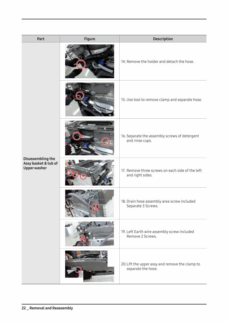
Disassembling the Assy basket & tub of Upper washer
14.Removetheholderanddetachthehose.
15.Usetooltoremoveclampandseparatehose.
16.Separatetheassemblyscrewsofdetergentandrinsecups.
17. Removethreescrewsoneachsideoftheleftandrightsides.
18.DrainhoseassemblyareascrewincludedSeparate3Screws.
19.LeftEarthwireassemblyscrewincludedRemove2Screws.
20.Lifttheupperassyandremovetheclamptoseparatethehose.
Removal and Reassembly _ 23
Part Figure Description
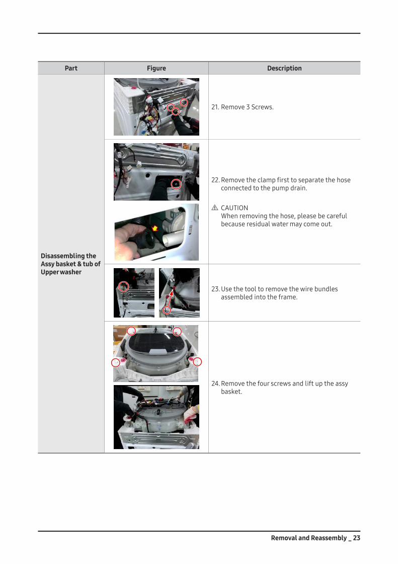
Disassembling the Assy basket & tub of Upper washer
21.Remove3Screws.
22.Removetheclampfirsttoseparatethehoseconnectedtothepumpdrain.
CAUTION Whenremovingthehose,pleasebecarefulbecauseresidualwatermaycomeout.
23.Usethetooltoremovethewirebundlesassembledintotheframe.
24.Removethefourscrewsandliftuptheassybasket.
24 _ Removal and Reassembly
Part Figure Description
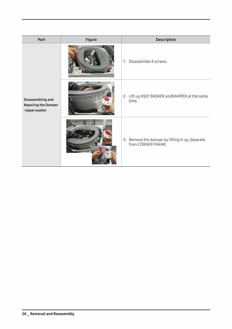
Disassembling andRepairing the Damper-Upper washer
1. Disassemble4screws.
2. LiftupASSYBASKERandDAMPERatthesametime.
3. RemovethedamperbyliftingItup,Separatefrom CORNER FRAME.
Removal and Reassembly _ 25
Part Figure Description
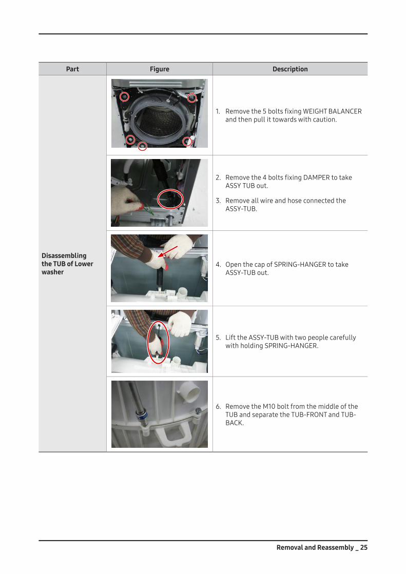
Disassembling the TUB of Lower washer
1. Removethe5boltsfixingWEIGHTBALANCERandthenpullittowardswithcaution.
2. Removethe4boltsfixingDAMPERtotakeASSY TUB out.
3. RemoveallwireandhoseconnectedtheASSY-TUB.
4. OpenthecapofSPRING-HANGERtotakeASSY-TUB out.
5. LifttheASSY-TUBwithtwopeoplecarefullywithholdingSPRING-HANGER.
6. RemovetheM10boltfromthemiddleoftheTUBandseparatetheTUB-FRONTandTUB-BACK.
26 _ Removal and Reassembly
Part Figure Description
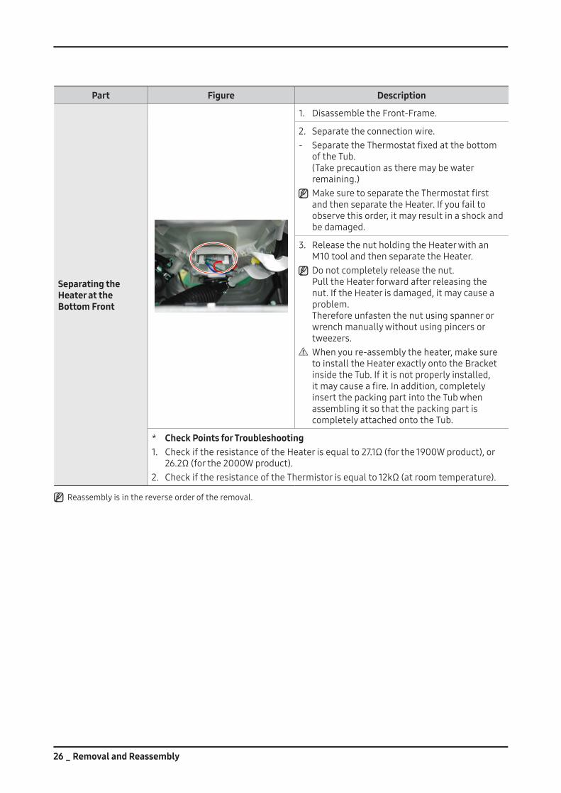
Separating the Heater at the Bottom Front
1. DisassembletheFront-Frame.
2. Separatetheconnectionwire.- SeparatetheThermostatfixedatthebottom
oftheTub. (Takeprecautionastheremaybewaterremaining.) MakesuretoseparatetheThermostatfirstandthenseparatetheHeater.Ifyoufailtoobservethisorder,itmayresultinashockandbedamaged.
3. ReleasethenutholdingtheHeaterwithanM10toolandthenseparatetheHeater. Donotcompletelyreleasethenut. PulltheHeaterforwardafterreleasingthenut.IftheHeaterisdamaged,itmaycauseaproblem. Thereforeunfastenthenutusingspannerorwrenchmanuallywithoutusingpincersortweezers. Whenyoure-assemblytheheater,makesuretoinstalltheHeaterexactlyontotheBracketinsidetheTub.Ifitisnotproperlyinstalled,itmaycauseafire.Inaddition,completelyinsertthepackingpartintotheTubwhenassemblingitsothatthepackingpartiscompletelyattachedontotheTub.
* Check Points for Troubleshooting1. CheckiftheresistanceoftheHeaterisequalto27.1Ω(forthe1900Wproduct),or
26.2Ω(forthe2000Wproduct).2. CheckiftheresistanceoftheThermistorisequalto12kΩ(atroomtemperature).
Reassemblyisinthereverseorderoftheremoval.
Removal and Reassembly _ 27
Part Figure Description
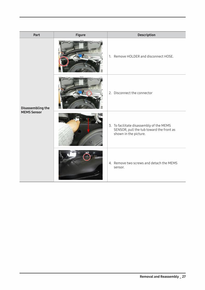
Disassembling the MEMS Sensor
1. RemoveHOLDERanddisconnectHOSE.
2. Disconnecttheconnector
3. TofacilitatedisassemblyoftheMEMSSENSOR,pullthetubtowardthefrontasshowninthepicture.
4. RemovetwoscrewsanddetachtheMEMSsensor.
28 _ Removal and Reassembly
Part Figure Description
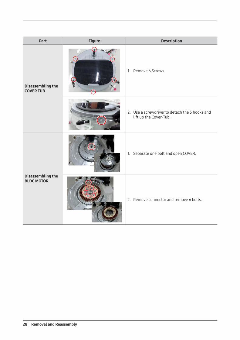
Disassembling the COVER TUB
1. Remove6Screws.
2. Useascrewdrivertodetachthe5hooksandliftuptheCover-Tub.
Disassembling the BLDC MOTOR
1. SeparateoneboltandopenCOVER.
2. Removeconnectorandremove6bolts.
Recommended