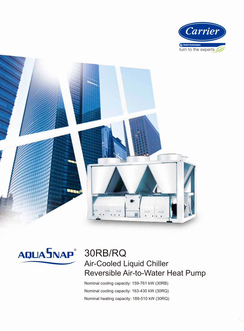
30RB/RQ Air-Cooled Liquid ChillerReversible Air-to-Water Heat PumpNominal cooling capacity: 159-761 kW (30RB)
Nominal cooling capacity: 163-430 kW (30RQ)
Nominal heating capacity: 189-510 kW (30RQ)
Easy and fast installation
Features
Benefits
3
Integrated hydronic module(except for 30RB672/802)
- Centrifugal high or low-pressure water pump (as required).
- Single or dual pump (as required) with operating time balancing and automatic
changeover to the back-up pump if a fault develops.
- Water filter protects the water pump against circulating debris.
- High-capacity membrane expansion tank ensures pressurization of the water circuit.
- Thermal insulation and anti-freeze protection down to -20oC by using an electric
resistance heater.
Simplified electrical connections
- A single power supply point without neutral (except for 30RB672/802).
- Main disconnect switch with high trip capacity.
- Transformer for safe 24 V control circuit supply included.
Fast commissioning
- Systematic factory operation test before shipment.
- Quick-test function for step-by-step verification of the instruments, electrical
components and motors.
The Aquasnap Puron liquid chillers/air-to-water heat pumps are designed for
commercial (air conditioning of villa, supermarket, office, hotel hospital etc.) or
industrial (lowtemperature process chillers etc.) applications.
Environment sound refrigerant HFC-410A of zero ozone depletion potential.
Standard unit with hydronic module (except for 30RB672/802) including all necessary
hydronic components, easy and fast installation to save time, space and money.
Low operating sound with no intrusive low-frequency noise, creates a better
working/living environment.
Electronic expansion valve (EXV) utilization, several compressors connected in
parallel lead to more economical operating cost.
Exceptional endurance tests ensure superior reliability to minimize chiller down-time.
Environmental sound
Ozone-friendly HFC-410A refrigerant
- Chlorine-free refrigerant of the HFC group with zero ozone depletion potential.
- Very efficient - gives an increased energy efficiency ratio.
Leak-tight refrigerant circuit.
- Brazed refrigerant connections for increased leaktightness.
- Reduction of leaks as no capillary tubes and flare connections are used.
- Verification of pressure transducers and temperature sensors without transferring
refrigerant charge.
Increased energy efficiency at part load
- The refrigerant circuit includes several compressors connected in parallel. At part
load, around 99% of the operating time, only the compressors that are absolutely
necessary operate.
- The electronic expansion device (EXV) allows operation at a lower condensing
pressure (EER and COP optimization).
- Dynamic superheat management for better utilization of the evaporator heat
exchange surface.
Reduced maintenance costs
- Maintenance-free scroll compressors.
- Fast diagnosis of possible incidents and their history via the Pro-Dialog Plus control.
- HFC-410A refrigerant is easier to use than other refrigerant blends.
Absolute reliability
4
Quiet operation
Economical operation
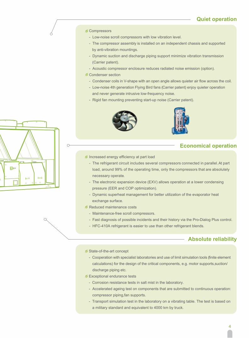
Compressors
- Low-noise scroll compressors with low vibration level.
- The compressor assembly is installed on an independent chassis and supported
by anti-vibration mountings.
- Dynamic suction and discharge piping support minimize vibration transmission
(Carrier patent).
- Acoustic compressor enclosure reduces radiated noise emission (option).
Condenser section
- Condenser coils in V-shape with an open angle allows quieter air flow across the coil.
- Low-noise 4th generation Flying Bird fans (Carrier patent) enjoy quieter operation
and never generate intrusive low-frequency noise.
- Rigid fan mounting preventing start-up noise (Carrier patent).
State-of-the-art concept
- Cooperation with specialist laboratories and use of limit simulation tools (finite element
calculations) for the design of the critical components, e.g. motor supports,suction/
discharge piping etc.
Exceptional endurance tests
- Corrosion resistance tests in salt mist in the laboratory.
- Accelerated ageing test on components that are submitted to continuous operation:
compressor piping,fan supports.
- Transport simulation test in the laboratory on a vibrating table. The test is based on
a military standard and equivalent to 4000 km by truck.
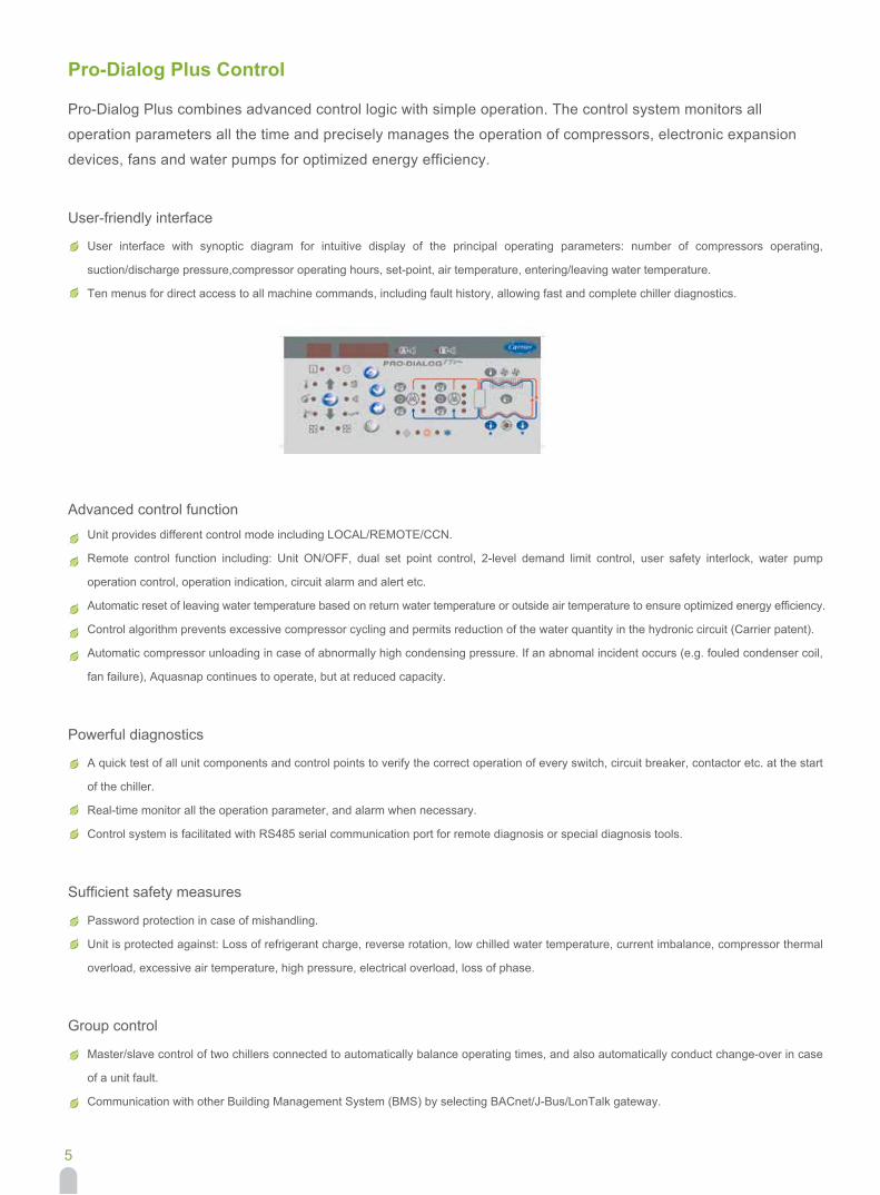
Pro-Dialog Plus combines advanced control logic with simple operation. The control system monitors all
operation parameters all the time and precisely manages the operation of compressors, electronic expansion
devices, fans and water pumps for optimized energy efficiency.
5
Pro-Dialog Plus Control
User-friendly interface
User interface with synoptic diagram for intuitive display of the principal operating parameters: number of compressors operating,
suction/discharge pressure,compressor operating hours, set-point, air temperature, entering/leaving water temperature.
Ten menus for direct access to all machine commands, including fault history, allowing fast and complete chiller diagnostics.
A quick test of all unit components and control points to verify the correct operation of every switch, circuit breaker, contactor etc. at the start
of the chiller.
Real-time monitor all the operation parameter, and alarm when necessary.
Control system is facilitated with RS485 serial communication port for remote diagnosis or special diagnosis tools.
Powerful diagnostics
Password protection in case of mishandling.
Unit is protected against: Loss of refrigerant charge, reverse rotation, low chilled water temperature, current imbalance, compressor thermal
overload, excessive air temperature, high pressure, electrical overload, loss of phase.
Sufficient safety measures
Master/slave control of two chillers connected to automatically balance operating times, and also automatically conduct change-over in case
of a unit fault.
Communication with other Building Management System (BMS) by selecting BACnet/J-Bus/LonTalk gateway.
Group control
Unit provides different control mode including LOCAL/REMOTE/CCN.
Remote control function including: Unit ON/OFF, dual set point control, 2-level demand limit control, user safety interlock, water pump
operation control, operation indication, circuit alarm and alert etc.
Automatic reset of leaving water temperature based on return water temperature or outside air temperature to ensure optimized energy efficiency.
Control algorithm prevents excessive compressor cycling and permits reduction of the water quantity in the hydronic circuit (Carrier patent).
Automatic compressor unloading in case of abnormally high condensing pressure. If an abnomal incident occurs (e.g. fouled condenser coil,
fan failure), Aquasnap continues to operate, but at reduced capacity.
Advanced control function
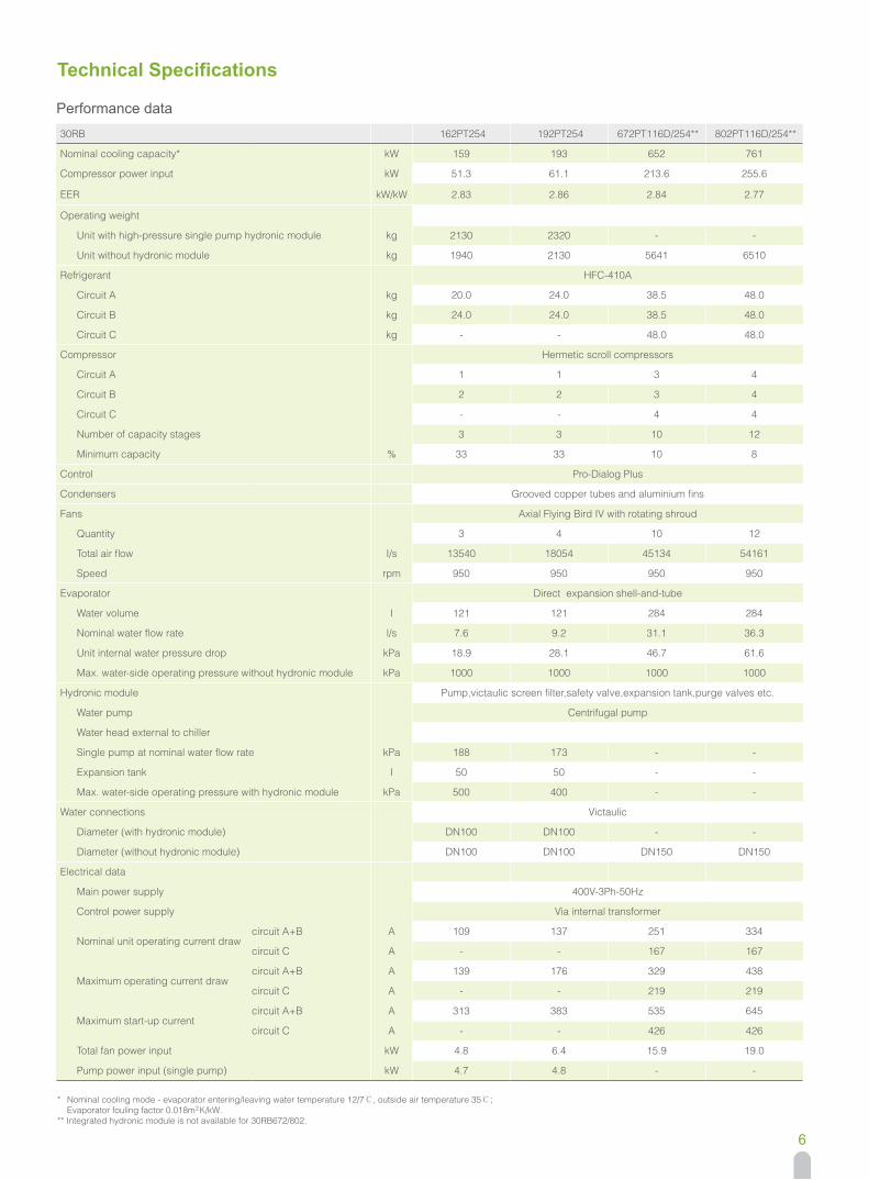
Performance data
6
Technical Specifications
* Nominal cooling mode - evaporator entering/leaving water temperature 12/7℃, outside air temperature 35℃; Evaporator fouling factor 0.018m2K/kW.** Integrated hydronic module is not available for 30RB672/802.
30RB 162PT254 192PT254 672PT116D/254** 802PT116D/254**
Nominal cooling capacity* kW 159 193 652 761
Compressor power input kW 51.3 61.1 213.6 255.6
EER kW/kW 2.83 2.86 2.84 2.77
Operating weight
Unit with high-pressure single pump hydronic module kg 2130 2320 - -
Unit without hydronic module kg 1940 2130 5641 6510
Refrigerant HFC-410A
Circuit A kg 20.0 24.0 38.5 48.0
Circuit B kg 24.0 24.0 38.5 48.0
Circuit C kg - - 48.0 48.0
Compressor Hermetic scroll compressors
Circuit A 1 1 3 4
Circuit B 2 2 3 4
Circuit C - - 4 4
Number of capacity stages 3 3 10 12
Minimum capacity % 33 33 10 8
Control Pro-Dialog Plus
Condensers Grooved copper tubes and aluminium fins
Fans Axial Flying Bird IV with rotating shroud
Quantity 3 4 10 12
Total air flow I/s 13540 18054 45134 54161
Speed rpm 950 950 950 950
Evaporator Direct expansion shell-and-tube
Water volume I 121 121 284 284
Nominal water flow rate l/s 7.6 9.2 31.1 36.3
Unit internal water pressure drop kPa 18.9 28.1 46.7 61.6
Max. water-side operating pressure without hydronic module kPa 1000 1000 1000 1000
Hydronic module Pump,victaulic screen filter,safety valve,expansion tank,purge valves etc.
Water pump Centrifugal pump
Water head external to chiller
Single pump at nominal water flow rate kPa 188 173 - -
Expansion tank I 50 50 - -
Max. water-side operating pressure with hydronic module kPa 500 400 - -
Water connections Victaulic
Diameter (with hydronic module) DN100 DN100 - -
Diameter (without hydronic module) DN100 DN100 DN150 DN150
Electrical data
Main power supply 400V-3Ph-50Hz
Control power supply Via internal transformer
Nominal unit operating current draw circuit A+B A 109 137 251 334
circuit C A - - 167 167
Maximum operating current drawcircuit A+B A 139 176 329 438
circuit C A - - 219 219
Maximum start-up currentcircuit A+B A 313 383 535 645
circuit C A - - 426 426
Total fan power input kW 4.8 6.4 15.9 19.0
Pump power input (single pump) kW 4.7 4.8 - -
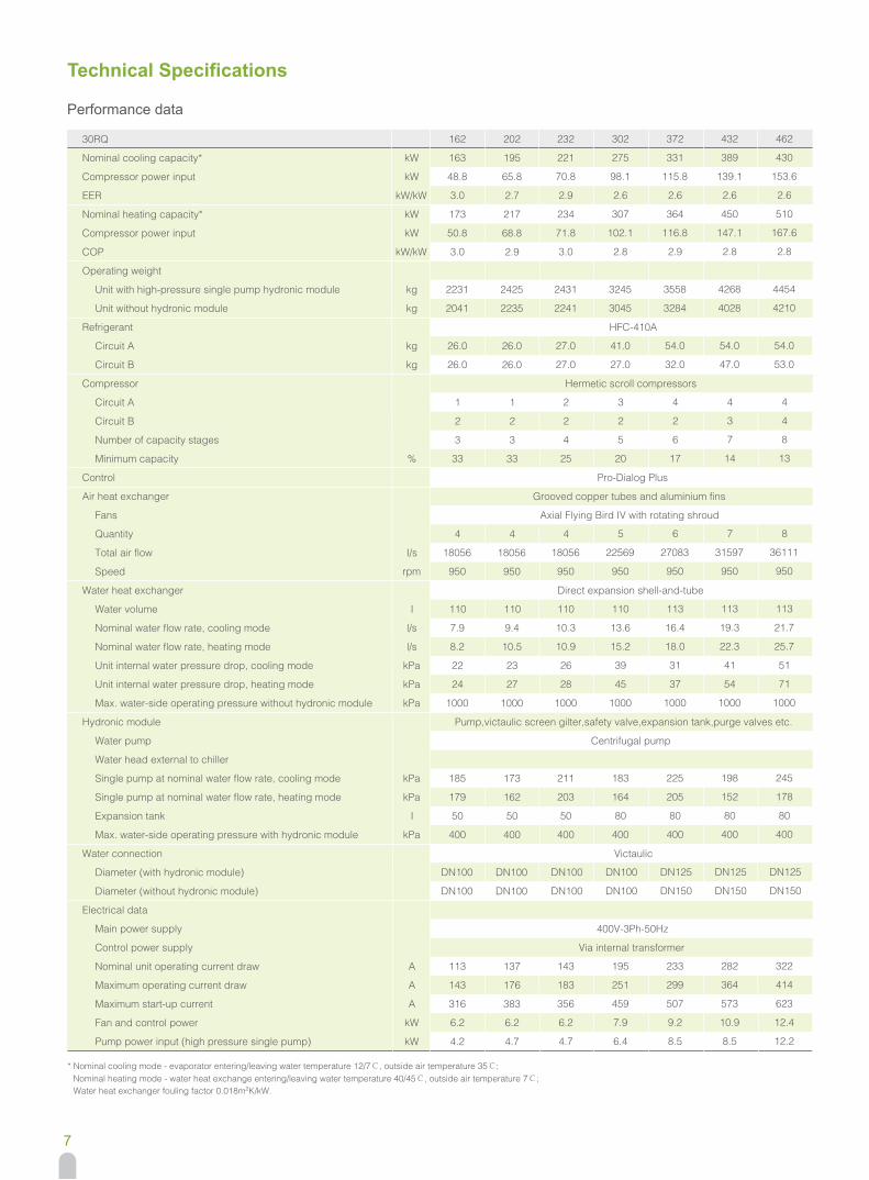
Technical Specifications
7
Performance data
HFC-410A
Hermetic scroll compressors
Pro-Dialog Plus
Grooved copper tubes and aluminium fins
Axial Flying Bird IV with rotating shroud
Direct expansion shell-and-tube
Centrifugal pump
Pump,victaulic screen gilter,safety valve,expansion tank,purge valves etc.
Victaulic
400V-3Ph-50Hz
Via internal transformer
Max. water-side operating pressure with hydronic module
30RQ
Nominal cooling capacity*
Compressor power input
EER
Nominal heating capacity*
Compressor power input
COP
Operating weight
Unit with high-pressure single pump hydronic module
Unit without hydronic module
Refrigerant
Circuit A
Circuit B
Compressor
Circuit A
Circuit B
Number of capacity stages
Minimum capacity
Control
Air heat exchanger
Fans
Quantity
Total air flow
Speed
Water heat exchanger
Water volume
Nominal water flow rate, cooling mode
Nominal water flow rate, heating mode
Unit internal water pressure drop, cooling mode
Unit internal water pressure drop, heating mode
Max. water-side operating pressure without hydronic module
Hydronic module
Water pump
Water head external to chiller
Single pump at nominal water flow rate, cooling mode
Single pump at nominal water flow rate, heating mode
Expansion tank
Water connection
Diameter (with hydronic module)
Diameter (without hydronic module)
Electrical data
Main power supply
Control power supply
Nominal unit operating current draw
Maximum operating current draw
Maximum start-up current
Fan and control power
Pump power input (high pressure single pump)
kW
kW
kW/kW
kW
kW
kW/kW
kg
kg
kg
kg
%
I/s
rpm
I
l/s
l/s
kPa
kPa
kPa
kPa
kPa
I
kPa
A
A
A
kW
kW
202
195
65.8
2.7
217
68.8
2.9
2425
2235
26.0
26.0
1
2
3
33
4
18056
950
110
9.4
10.5
23
27
1000
173
162
50
400
DN100
DN100
137
176
383
6.2
4.7
162
163
48.8
3.0
173
50.8
3.0
2231
2041
26.0
26.0
1
2
3
33
4
18056
950
110
7.9
8.2
22
24
1000
185
179
50
400
DN100
DN100
113
143
316
6.2
4.2
232
221
70.8
2.9
234
71.8
3.0
2431
2241
27.0
27.0
2
2
4
25
4
18056
950
110
10.3
10.9
26
28
1000
211
203
50
400
DN100
DN100
143
183
356
6.2
4.7
302
275
98.1
2.6
307
102.1
2.8
3245
3045
41.0
27.0
3
2
5
20
5
22569
950
110
13.6
15.2
39
45
1000
183
164
80
400
DN100
DN100
195
251
459
7.9
6.4
372
331
115.8
2.6
364
116.8
2.9
3558
3284
54.0
32.0
4
2
6
17
6
27083
950
113
16.4
18.0
31
37
1000
225
205
80
400
DN125
DN150
233
299
507
9.2
8.5
432
389
139.1
2.6
450
147.1
2.8
4268
4028
54.0
47.0
4
3
7
14
7
31597
950
113
19.3
22.3
41
54
1000
198
152
80
400
DN125
DN150
282
364
573
10.9
8.5
462
430
153.6
2.6
510
167.6
2.8
4454
4210
54.0
53.0
4
4
8
13
8
36111
950
113
21.7
25.7
51
71
1000
245
178
80
400
DN125
DN150
322
414
623
12.4
12.2
* Nominal cooling mode - evaporator entering/leaving water temperature 12/7℃, outside air temperature 35℃; Nominal heating mode - water heat exchange entering/leaving water temperature 40/45℃, outside air temperature 7℃; Water heat exchanger fouling factor 0.018m2K/kW.
8
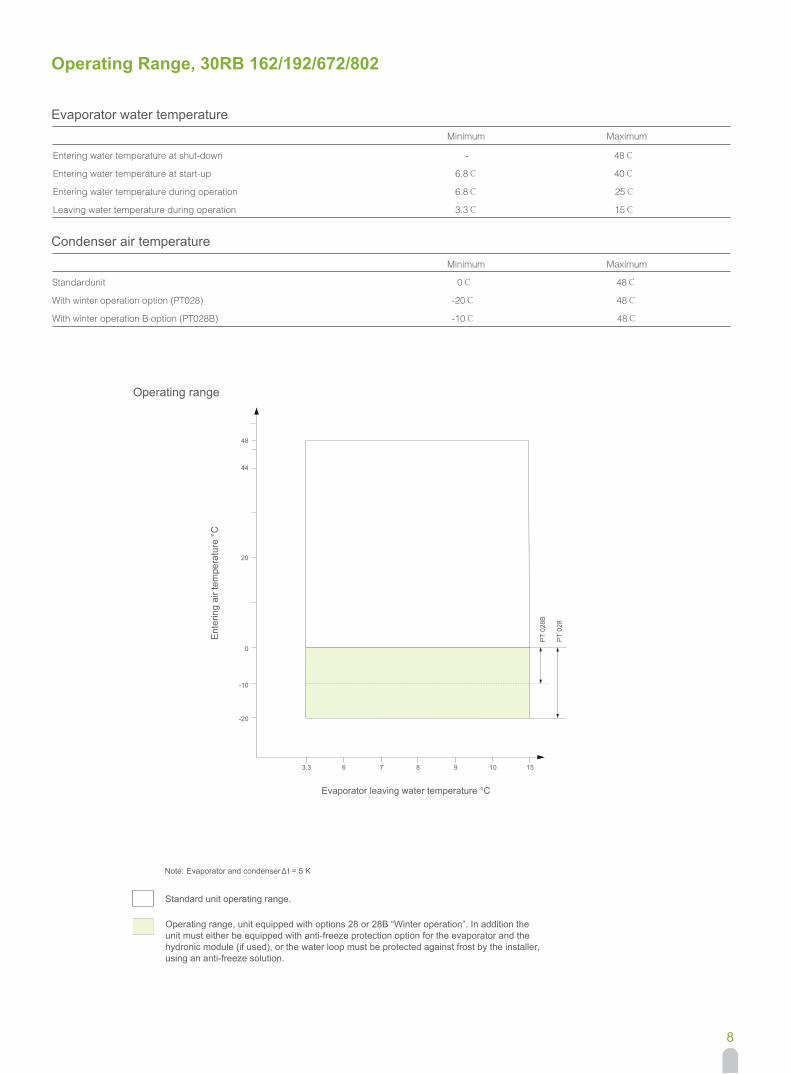
Operating Range, 30RB 162/192/672/802
Evaporator water temperature Minimum Maximum
Entering water temperature at shut-down - 48℃
Entering water temperature at start-up 6.8℃ 40℃
Entering water temperature during operation 6.8℃ 25℃
Leaving water temperature during operation 3.3℃ 15℃
Condenser air temperature Minimum Maximum
48℃0℃Standardunit
With winter operation option (PT028) -20℃ 48℃
With winter operation B option (PT028B) -10℃ 48℃
Operating range
Ent
erin
g ai
r tem
pera
ture
°C
Evaporator leaving water temperature °C
Note: Evaporator and condenser Δt = 5 K
Standard unit operating range.
Operating range, unit equipped with options 28 or 28B “Winter operation”. In addition the unit must either be equipped with anti-freeze protection option for the evaporator and the hydronic module (if used), or the water loop must be protected against frost by the installer, using an anti-freeze solution.
3.3 6 7 8 9
-20
48
44
20
0
1510
-10
PT
028B
PT
028
9
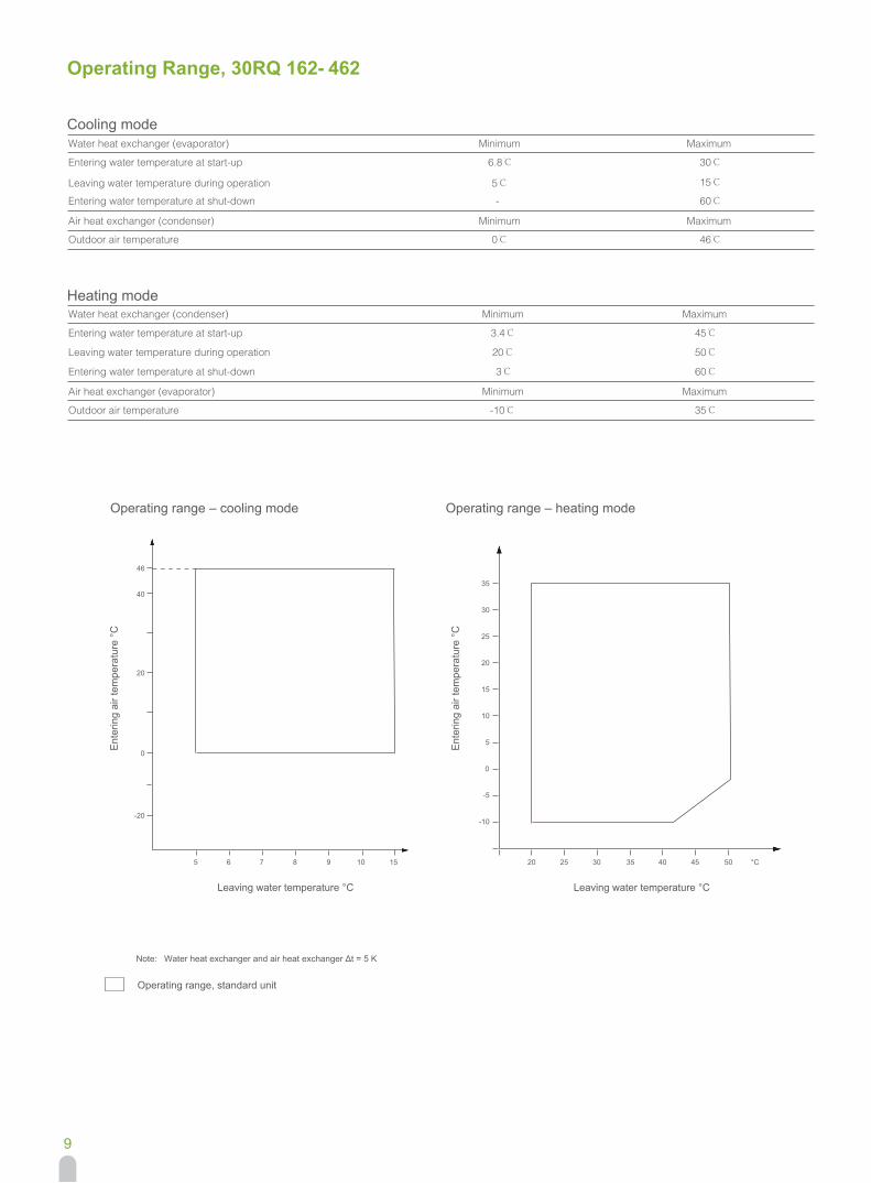
Operating Range, 30RQ 162- 462
Cooling modeWater heat exchanger (evaporator) Minimum Maximum
Minimum Maximum
Entering water temperature at start-up 6.8℃ 30℃
Leaving water temperature during operation 5℃ 15℃
Entering water temperature at shut-down - 60℃
Air heat exchanger (condenser)
Outdoor air temperature 0℃ 46℃
Heating modeWater heat exchanger (condenser) Minimum Maximum
Minimum Maximum
Entering water temperature at start-up 3.4℃ 45℃
Leaving water temperature during operation 20℃ 50℃
Entering water temperature at shut-down 3℃ 60℃
Air heat exchanger (evaporator)
Outdoor air temperature -10℃ 35℃
Operating range – cooling mode
Ent
erin
g ai
r tem
pera
ture
°C
Leaving water temperature °C
Note: Water heat exchanger and air heat exchanger Δt = 5 K
Operating range, standard unit
5 6 7 8 9 10
-20
46
40
20
0
15
Operating range – heating mode
Ent
erin
g ai
r tem
pera
ture
°C
Leaving water temperature °C
°C20 25 30 35 40 45 50
-10
-5
0
5
10
15
20
25
30
35
10
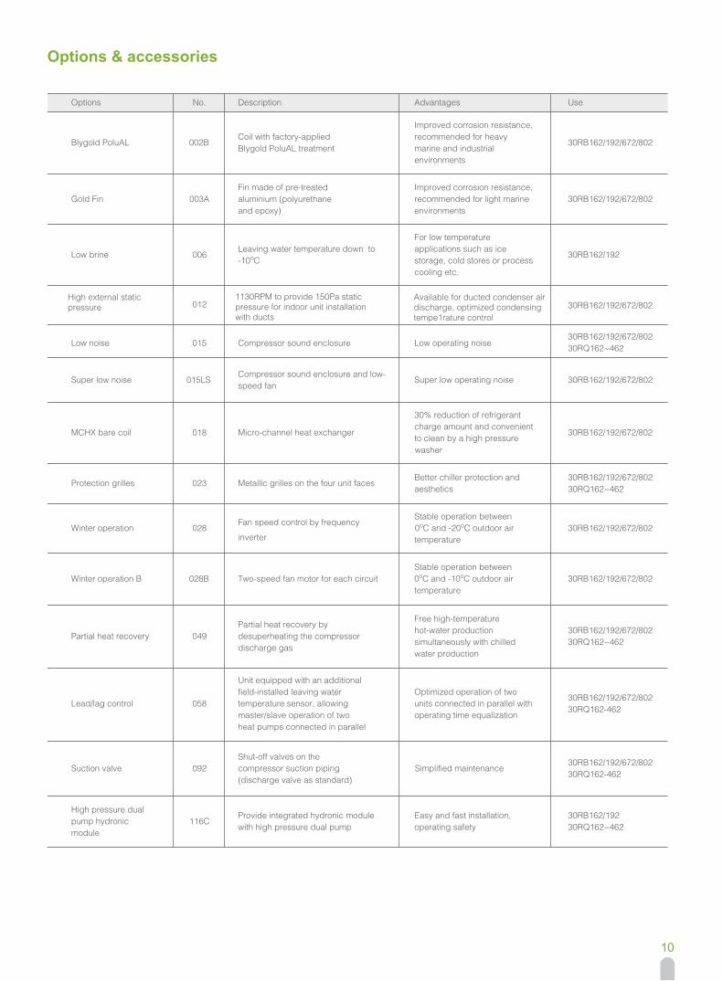
Options & accessories
Options
Blygold PoluAL
Gold Fin
Low brine
Low noise
30RB162/192/672/802
Super low noise
MCHX bare coil
Protection grilles
Winter operation
Winter operation B
Partial heat recovery
Lead/lag control
Suction valve
High pressure dual pump hydronic module
No.
002B
003A
006
015
015LS
018
023
028
028B
049
058
092
116C
Description
Coil with factory-applied Blygold PoluAL treatment
Fin made of pre-treated aluminium (polyurethane and epoxy)
Leaving water temperature down to -10oC
Compressor sound enclosure
Compressor sound enclosure and low-speed fan
Micro-channel heat exchanger
Metallic grilles on the four unit faces
inverter
Fan speed control by frequency
Two-speed fan motor for each circuit
Partial heat recovery by desuperheating the compressor discharge gas
Unit equipped with an additional field-installed leaving water temperature sensor, allowing master/slave operation of two heat pumps connected in parallel
Shut-off valves on the compressor suction piping(discharge valve as standard)
Provide integrated hydronic module with high pressure dual pump
washer
Advantages
Improved corrosion resistance, recommended for heavy marine and industrial environments
Improved corrosion resistance, recommended for light marine environments
For low temperature applications such as ice storage, cold stores or process cooling etc.
Low operating noise
Super low operating noise
30% reduction of refrigerant charge amount and convenient to clean by a high pressure
Better chiller protection and aesthetics
Stable operation between 0oC and -20oC outdoor air temperature
Stable operation between 0oC and -10oC outdoor air temperature
Free high-temperature hot-water production simultaneously with chilled water production
Optimized operation of two units connected in parallel with operating time equalization
Simplified maintenance
Easy and fast installation, operating safety
Use
30RB162/192/672/802
30RB162/192/672/802
30RB162/192
30RB162/192/672/80230RQ162~462
30RB162/192/672/802
30RB162/192/672/80230RQ162~462
30RB162/192/672/802
30RB162/192/672/802
30RB162/192/672/80230RQ162~462
30RB162/192/672/80230RQ162-462
30RB162/192/672/80230RQ162-462
30RB162/192/672/802
30RB162/19230RQ162~462
High external static pressure 012
1130RPM to provide 150Pa static pressure for indoor unit installation with ducts
Available for ducted condenser air discharge, optimized condensing tempe1rature control
11
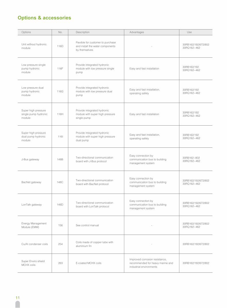
Options & accessories
Options
Unit without hydronic module
Low pressure single pump hydronic module
Low pressure dual pump hydronic module
Super high pressure single pump hydronic module
Super high pressure dual pump hydronic module
J-Bus gateway
BacNet gateway
LonTalk gateway
Energy Management Module (EMM)
Cu/Al condenser coils
Super Enviro shield MCHX coils
No.
116D
116F
116G
116H
116I
148B
148C
148D
156
254
263
Description
Flexible for customer to purchase and install the water components by themselves
Provide integrated hydronic module with low pressure single pump
Provide integrated hydronic module with low pressure dual pump
Provide integrated hydronic module with super high pressure single pump
Provide integrated hydronic module with super high pressure dual pump
Two-directional communication board with J-Bus protocol
Two-directional communication board with BacNet protocol
Two-directional communication board with LonTalk protocol
See control manual
Coils made of copper tube with aluminium fin
E-coated MCHX coils
Advantages
-
Easy and fast installation
Easy and fast installation, operating safety
Easy and fast installation
Easy and fast installation, operating safety
Easy connection by communication bus to building management system
Easy connection by communication bus to building management system
Easy connection by communication bus to building management system
-
-
Improved corrosion resistance, recommended for heavy marine and industrial environments
Use
30RB162/192/672/80230RQ162~462
30RB162/19230RQ162~462
30RB162/19230RQ162~462
30RB162/19230RQ162~462
30RB162/19230RQ162~462
30RB162~80230RQ162~462
30RB162/192/672/80230RQ162~462
30RB162/192/672/80230RQ162~462
30RB162/192/672/80230RQ162~462
30RB162/192/672/802
30RB162/192/672/802
12
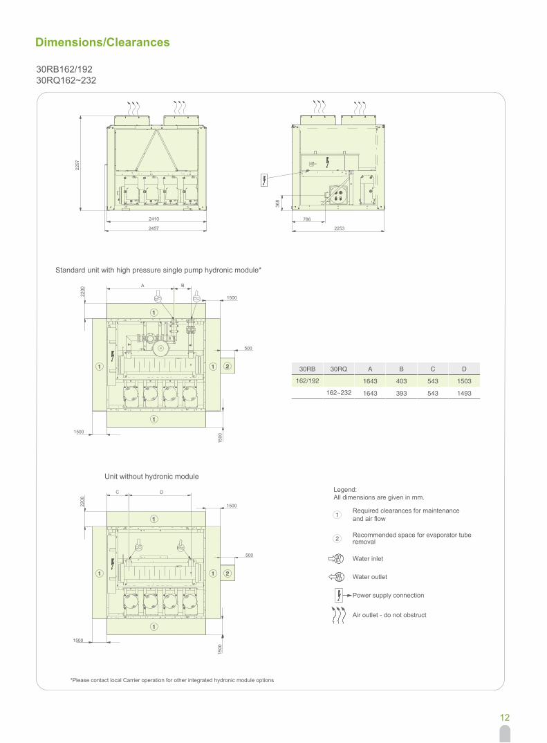
Dimensions/Clearances
2297
368
2410
2457 2253
786
1500
500
1500
2200
1500
2
1
1 1
1
C D
1500
A B
500
1500
1500
2200
1
1 1 2
1
Standard unit with high pressure single pump hydronic module*
30RB162/19230RQ162~232
Unit without hydronic module
*Please contact local Carrier operation for other integrated hydronic module options
30RB
162/192
30RQ
162~232
A
1643
1643
B
403
393
C
543
543
D
1503
1493
2
1Required clearances for maintenanceand air flow
Recommended space for evaporator tuberemoval
Water inlet
Water outlet
Power supply connection
Air outlet - do not obstruct
Legend:All dimensions are given in mm.
13
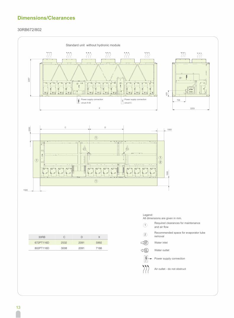
Legend:All dimensions are given in mm.
Dimensions/Clearances
30RB672/802
30RB
672PT116D
802PT116D
C
2532
3008
D
2091
2091
X
5992
7186
1
11
1
2
2
1
1500
1500
X
1500
2200
2297
425
736
DC
2253
Power supply connection
circuit A+B
Power supply connection
circuit C
Required clearances for maintenanceand air flow
Recommended space for evaporator tuberemoval
Water inlet
Water outlet
Power supply connection
Air outlet - do not obstruct
Standard unit without hydronic module
14
Dimensions/Clearances
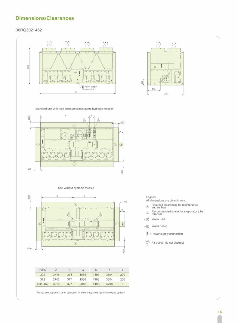
30RQ302~462
2
1
368
786
2297
1500
2200
BA
1500
2200
150015
00
Y
X
1500
1500
Y
1
1
1
1
2
1
1
1
1
2
DC
2253
30RQ
302
372432~462
A
2745
2742
B
314
317
C
1566
1566
D
1493
1493
X
3604
3604
Y
200
2003218 327 2042 1493 4798 0
Power supply connection
Required clearances for maintenance
Legend:All dimensions are given in mm.
Recommended space for evaporator tuberemoval
and air flow
Water inlet
Water outlet
Power supply connection
Air outlet - do not obstruct
Standard unit with high pressure single pump hydronic module*
Unit without hydronic module
*Please contact local Carrier operation for other integrated hydronic module options
Dimensions (mm)
15
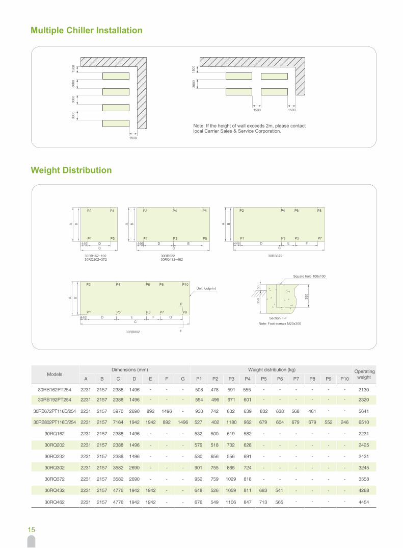
Multiple Chiller Installation
F
F
5035
0 350
30RB672
FP7
P8 P10
P9G446
P3
P4P2
P1
B
D
A
C
P6
P5E
30RB802
Unit footprint
Square hole 100x100
Section F-FNote: Foot screws M20x300
FP7
P8
30RB52230RB162~19230RQ202~372 30RQ432~462
446P3
P4P2
P1
B
D
A
C
P6
P5EE
P5
P6
C
A
D
B
P1
P2 P4
P3446446
P3
P4P2
P1
B
D
A
C
Weight Distribution
Weight distribution (kg)Models
A B C D E F G P5 P6 P7 P8 P9 P10P1 P2 P3 P4
Operatingweight
30RB192PT254 2231 2157 2388 1496 - - - - - - - - -554 496 671 601 2320
30RB162PT254 2231 2157 2388 1496 - - - - - - - - -508 478 591 555 2130
30RB672PT116D/254 2231 2157 5970 2690 892 - 832 638 568 461 - -930 742 832 639 56411496
30RB802PT116D/254 2231 2157 7164 1942 1942 892 1496 679 604 679 679 552 246527 402 1180 962 6510
30RQ202 2231 2157 2388 1496 - - - - - - - - -579 518 702 628 2425
30RQ162 2231 2157 2388 1496 - - - - - - - - -532 500 619 582 2231
30RQ232 2231 2157 2388 1496 - - - - - - - - -530 656 556 691 2431
30RQ302 2231 2157 3582 2690 - - - - - - - - -901 755 865 724 3245
30RQ372 2231 2157 3582 2690 - - - - - - - - -952 759 1029 818 3558
30RQ432 2231 2157 4776 1942 1942 - - 683 541 - - - -648 526 1059 811 4268
30RQ462 2231 2157 4776 1942 1942 - - 713 565 - - - -676 549 1106 847 4454
3000
1500
3000
3000
1500
3000
1500
15001500
Note: If the height of wall exceeds 2m, please contactlocal Carrier Sales & Service Corporation.
16
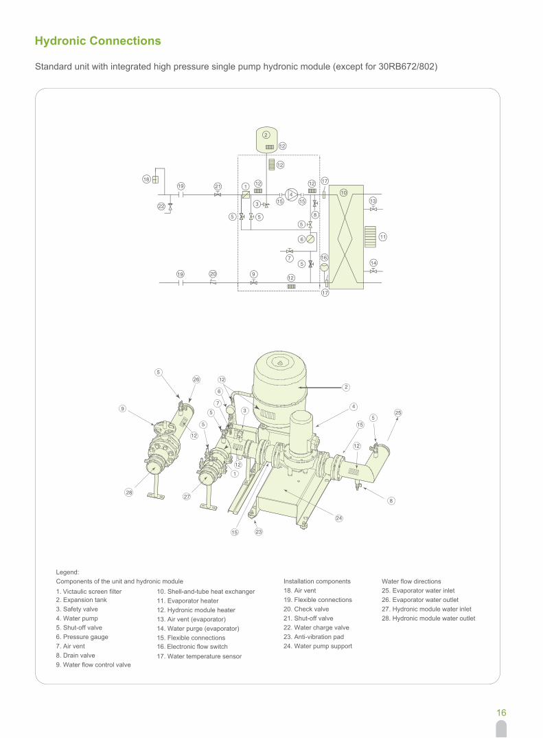
Hydronic Connections
Standard unit with integrated high pressure single pump hydronic module (except for 30RB672/802)
1
2
3
4
5
5
6
7
9
21
19
12
1212
14
131515
16
55 8
18
17
17
12
12
1910
11
20
12
12
5
8
25
15
15
4
2
24
27
23
12
39
265
5
5
7
6
28
12
1
22
Legend:Components of the unit and hydronic module
2. Expansion tank1. Victaulic screen filter
3. Safety valve4. Water pump5. Shut-off valve6. Pressure gauge7. Air vent8. Drain valve9. Water flow control valve
10. Shell-and-tube heat exchanger11. Evaporator heater12. Hydronic module heater13. Air vent (evaporator)14. Water purge (evaporator)15. Flexible connections
17. Water temperature sensor16. Electronic flow switch
Installation components18. Air vent19. Flexible connections20. Check valve21. Shut-off valve22. Water charge valve23. Anti-vibration pad24. Water pump support
25. Evaporator water inletWater flow directions
26. Evaporator water outlet27. Hydronic module water inlet28. Hydronic module water outlet
17
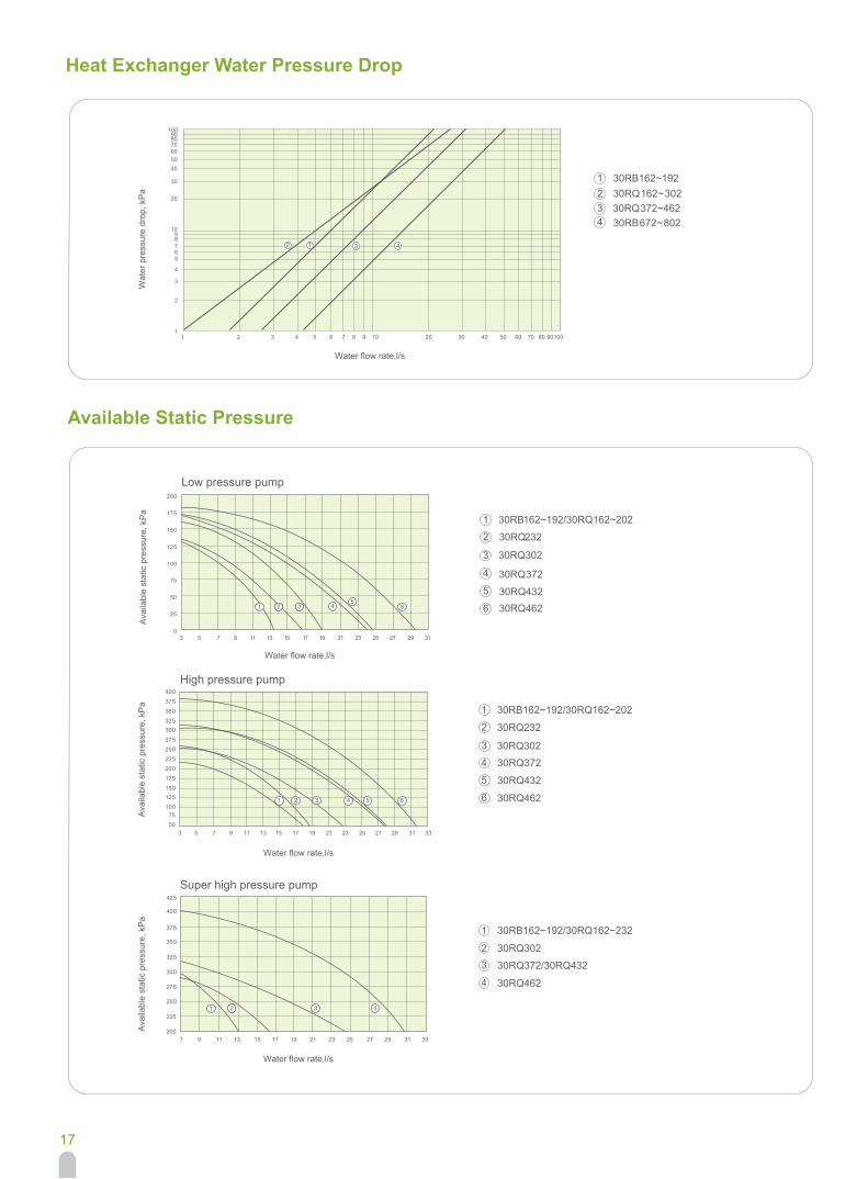
Heat Exchanger Water Pressure Drop
30RB162~192/30RQ162~2021
30RQ232 2
30RQ302 3
30RQ3724
30RQ432 5
30RQ462 6
1
23
4
225
200
250
275
300
325
350
375
400
425
7 9 11 13 15 17 19 21 23 25 27 29 31 33
2 3 4
100908070605040
30
20
98
100
10
765
4
3
2
2010 30 40 50 60 70 80 902 3 4 5 7 8 91
1
4312
4
30RB162~192 30RQ 162 ~ 30230RQ 372~46230RB 672 ~ 802
21
3
5075
100125150175200225250275300325350375400
3 5 7 9 11 13 15 17 19 21 23 25 27 29 31 33
2 5 643
30RB162~192/30RQ162~232
30RQ302
30RQ372/30RQ432
30RQ462
Wat
er p
ress
ure
drop
, kP
a
Available Static Pressure
High pressure pump
Super high pressure pump
Ava
ilabl
e st
atic
pre
ssur
e, k
Pa
Ava
ilabl
e st
atic
pre
ssur
e, k
Pa
Water flow rate,l/s
Water flow rate,l/s
Water flow rate,l/s
6
18
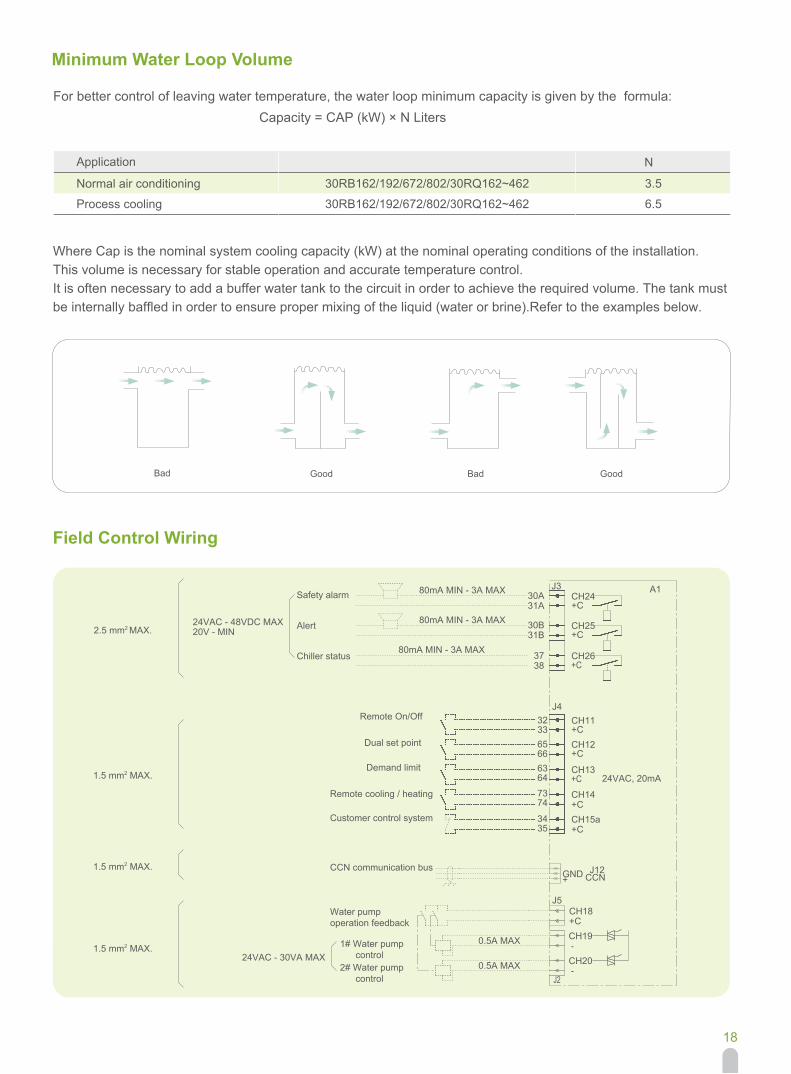
Minimum Water Loop Volume
Field Control Wiring
For better control of leaving water temperature, the water loop minimum capacity is given by the formula: Capacity = CAP (kW) × N Liters
Application
Normal air conditioning
Process cooling
Bad Good Bad Good
N
3.5
6.5
30RB162/192/672/802/30RQ162~462
30RB162/192/672/802/30RQ162~462
Where Cap is the nominal system cooling capacity (kW) at the nominal operating conditions of the installation.This volume is necessary for stable operation and accurate temperature control.It is often necessary to add a buffer water tank to the circuit in order to achieve the required volume. The tank must be internally baffled in order to ensure proper mixing of the liquid (water or brine).Refer to the examples below.
A180mA MIN - 3A MAX
3837
31B30B
31A30A
J3
80mA MIN - 3A MAX
80mA MIN - 3A MAX
20V - MIN24VAC - 48VDC MAX
2.5 mm2 MAX.
+C
CH15a
CH13
323365666364
7374
3435
24VAC, 20mA
CH14+C
+C
CH12+C
CH11+C
CH26+C
CH25+C
CH24+C
CCNGND
+C
J12
J5
J4
+
CH18
1.5 mm2 MAX.
1.5 mm2 MAX.
0.5A MAX
0.5A MAX
CH19-
CH20--
J2
1.5 mm2 MAX.24VAC - 30VA MAX
Safety alarm
Remote On/Off
Dual set point
Demand limit
Remote cooling / heating
Customer control system
CCN communication bus
Water pump operation feedback
1# Water pump control 2# Water pump control
Alert
Chiller status

CAT_30RB/RQ_E-1503_04
CAT_30RB/RQ_E-1409_03
Mar, 2015
The Manufacturer reserves the right to change any produt specifications without prior notices Version:
Supersede:
Effective Date:
Recommended