5S32J N,9S/
N91-2'3 TEST RESULTS OF THE MODIFIED SPACE SHUTTLE MAIN ENGINE /4/ 7
AT THE MARSHALL SPACE FLIGHT CENTER TECHNOLOGY TEST BED FACILITY (
J. Cook, D. Dumbacher, M. Ise, and C. Singer Marshall Space Flight Center
Marshall Space Flight Center, Alabama
ABSTRACT Ah7 74'Po( A modified space shuttle main engine (SSME), which primarily includes an enlarged throat main
combustion chamber with the acoustic cavities removed and a main injector with the stability control baffles removed, was tested at the Marshall Space Flight Center's (MSFC) technology test bed facility. This one-of-a-kind engine's design changes are being evaluated for potential incor-poration in the shuttle flight program in the mid-199O's. Engine testing was initiated on September 15, 1988, and has accumulated 1,915 seconds and 19 starts.
Testing is being conducted to characterize the engine system performance, combustion stabil-ity with the baffle-less injector, and both low pressure oxidizer turbopump (LPOTP) and high pressure oxidizer turbopump (HPOTP) for suction performance. These test results are summarized and compared with the SSME flight configuration data base.
Testing of this new generation SSFIE is the first product from the technology test bed (TTB). Figure test plans for the TTB include the highly instrumented flight configuration SSME and advanced liquid propulsion technology items.
INTRODUCTION
In July 1971, the National Aeronautics and Space Administration (NASA) awarded a contract to develop a reusable engine in an effort to depart from the Apollo program ideal of expendable engines and vehicles. It was from this initial contract that the SSME has evolved.
The SSNE is a liquid oxygen/liquid hydrogen engine utilizing a two-stage combustion cycle. Figure 1 illustrates the SSME propellant flow paths. In the first stage, an extremely fuel rich mixture is partially burned in two preburners. The two exhaust streams of this combustion are then channeled to drive two high pressure turbopumps. The hot gas is finally injected into the main combustion chamber where final combustion of the propellants occur. The SSHE is a throttle-able engine which can operate from 65% rated power level (RPL) to levels exceeding 109% RPL. The normal 100% power level corresponds to 470,000 lb of thrust (vacuum) or 375,000 lb of thrust (sea level), with a specific impulse (Isp) of 453.5 seconds (vacuum). The SSME operates at a chamber pressure of 3,006 psia at 100% RPL with a mixture ratio of 6.0:1. The nozzle provides an expansion ratio of 77.5:1. Other engine particulars are given in Table I.
The modified SSME tested at MSFC's TTB is a one-of-a-kind engine. Its uniqueness comes from the elimination of the acoustic cavities and stability control injector baffle elements in the main combustion chamber (MCC) and from an increase in the 14CC throat area of approximately 10%.
Testing at TTB was conducted to characterize engine system performance effects, combustion stability, and suction performance of the standard low pressure and high pressure oxidizer pumps, as well as the modified high pressure liquid oxygen (lox) pump. This test program also served as a pathfinder series to activate the TTB facility which will be used to test the highly instrumen-ted flight configuration SSME. The test facility, test programs, and their objectives, results, and conclusions will be discussed in the following sections.
FACILITY
The TTB facility has a prestigious history in propulsion systems testing. The facility was constructed by MSFC in the early 1960's to static test fire the S-iC stage of the Saturn V. This stage consisted of five F-i engines and developed 7.5 million pounds of thrust.
The static test stand is a vertical stand 406-ft high, including the main derrick boom. The superstructure is 267-ft high and the foundation is keyed into bedrock approximately 45 ft below grade. The structure has a gross area of 32,336 ft 2 . Originally the structure was capable of supporting 7.5 million pounds of thrust, and could accommodate test articles 170-ft long and 40 ft in diameter. In the late i97O's, the test stand was modified structurally to conduct a series of tests on the space shuttle external tank (ET). Upon conclusion of this test series, the stand remained inactive until the modifications to accommodate the advanced SSME testing began in 1986. The current configuration is shown in Fig. 2. The stand was activated in 1988 with a series of
Approved for public release; distribution is unlimited.
107
https://ntrs.nasa.gov/search.jsp?R=19910014930 2018-08-27T06:59:18+00:00Z

cold flow checkout tests and a functional check of the Firex and deluge system. The technical specifications of the facility are given in Table II.
All control and instrumentation operations are controlled from a 27,000-ft 2 blockhouse located approximately 200 yards east of the test stand (Fig. 2). This building contains instru-mentation signal conditioning and recording systems, closed-circuit television monitoring equip-ment, area warning systems, and the controls for all facility remotely operated valves. A tunnel system connects the blockhouse to the test stand. A General Electric programmable computer controls the sequencing and actuation of all facility valves. This unit also receives and ana-lyzes approximately 125 channels of data that make up the facility automated cutoff system. The system is used to issue programmed and nonprogrammed test terminations. All facility valve actuation and other events are recorded on the discrete event evaluator (DEE). A typical printout from the DEE is shown in Fig. 3. This device allows for real time evaluation of facility valve Operation.
The instrumentation system is capable of accepting 750 channels of digital data and 216 channels of analog data. Digital data can be recorded at a rate of 50 samples per second.
The liquid hydrogen storage facility consists of two vacuum-jacketed spherical tanks with a capacity of 480,000 gallons and can pump liquid hydrogen into the test stand run tank at a rate of 2,000 gallons per minute. The liquid hydrogen run tank capacity is 75,000 gallons. The lox facility can store 71,000 gallons in three horizontally mounted tanks. The lox storage facility can pump lox into the run tank at an approximate rate of 500 gallons per minute. The cylindrical lox run tank capacity is approximately 23,000 gallons.
The water for the Firex and deluge system and flame deflector are supplied from storage tanks capable of holding 7 million gallons. The test stand supply is fed by 13 diesel-powered pumps which are capable of delivering approximately 200,000 gallons per minute at a pressure of 150 psig to the test stand through a 96-in diameter pipe. This is equivalent to filling an average size pool every 7 seconds.
PATHFINDER SERIES
The overall goals of the initial TTB test series were twofold. The initial four tests, known as the Pathfinder series, were to demonstrate the enhanced capabilities of the modified Saturn test stand. The second series, consisting of 15 tests, was to evaluate and characterize the performance of an advanced SSME. A test series matrix is listed in Table III.
The Pathfinder series consisted of TTB-001 through TTB-004. This series was used to demon-strate the facility's capability to satisfy the engine interface requirements of propellant, pneumatic, hydraulic, and electrical supply; data acquisition; and chill down time as specified in the interface control documents. This was accomplished initially with a 1.5-second ignition test. After successfully meeting these requirements, the next test was a 15-second mainstage test at 100% RPL. This test demonstrated propellant supply system mainstage performance, flame deflector cooling capability, and served to check the effects of vibration on facility-mounted video and photographic equipment. The third test was prematurely terminated at 5.06 seconds due to an erroneous signal from accelerometers located on the main combustion chamber. Subsequently, a fourth test to check out the results of remotely mounting the main engine controller (NEC), and to demonstrate the facility's ability to vent and repressurize the lox run tank during a test was successfully completed with a duration of 45 seconds. The lox run tank venting profile was required to effectively evaluate the performance of the low pressure and high pressure lox pumps.
With the facility objectives successfully accomplished, the engine performance evaluation was then initiated.
TEST OBJECTIVES AND RESULTS
Fifteen tests conducted at the TTB facility accumulated the data required to characterize the performance of the modified SSME. The major objective of combustion stability was demonstrated during the initial eight tests. The second major objective was to evaluate the performance of the standard low and high pressure lox pumps, and to test a redesigned high pressure lox pump. The pumps were analyzed for suction performance with a variey of pump inlet conditions. A third major objective, specific impulse of the modified SSME, was determined using facility mounted thrust measurement and propellant flow instrumentation. These objectives and future test plans will be discussed in detail in the following paragraphs.
Combustion Stability
Combustion stability is a major design parameter of any propulsion system. High frequency combustion instability occurs when the combustion process is pressure and/or velocity sensitive at
los

time scales which allow coupling with the chamber acoustics. In the SSME, this usually occurs at low hydrogen temperatures and/or high oxidizer temperatures. The initial design of the SSME incorporated baffles which divided the coaxial injector faceplate into six compartments (Fig. 4A). The baffles are 2-in long and were designed to segment the more destructive fundamental acoustic modes. The forward area of the combustion chamber liner has a ring of acoustic cavities (Fig. 4B). These cavities are designed to dampen baffle compartment modes and other higher frequency modes. These stability aids were eliminated from the modified SSME design. An engine is regarded as dynamically stable if normal combustion is restored after being disrupted by an artificial device. The usual method to determine stability is to temporarily disrupt the combustion process with a nondirectional pyrotechnic device. Stability is determined by the time required for the engine to return to normal combustion conditions.
To demonstrate the combustion stability characteristics of the modified SSME, small explosive charges were attached to the main injector face and positioned near the thrust chamber wall where a pressure antinodal point is present for all resonant modes of instability (Fig. 5 and 6). Charges ranged from 10 grains to 15 grains in size and were detonated during the engine start transient. Figure 7 gives a cross section of a typical stability rating bomb. Each test included the detonation of two charges. Figure 8 lists the time of detonation, size of charge, and chamber pressure at time of detonation for each test. Triaxial accelerometers were the principle measure-ments used to detect combustion chamber resonances. The triaxial accelerometers were physically mounted external to the main combustion chamber (Fig. 9). Axial accelerometers were installed at the engine gimbal mounts. A fluctuating pressure measurement was placed in the main injector lox inlet dome.
The TTB combustion stability test series consisted of eight tests, and resulted in 16 suc-cessful bomb detonations. Fifteen of these detonations occurred at the targeted combustion pres-sure with only one bomb having to be prematurely detonated when a test was cut by an erroneous signal. The induced flow instabilities had minimal effect on engine start or thrust buildup. As predicted, the pressure occillations were dampened out within an average of 6 msec revealing no instability (Fig. 10).
LPOTP and HPOTP Performance
The enlarged throat 14CC had several beneficial qualities. Lowering of system operating pressures and temperatures created a lower stress level resulting in increased hardware life. The TTB test program was used to evaluate the low and high pressure lox pumps' ability to operate at these lower system pressures and higher flow coefficients (Fig. 11). Figure 12 gives the thrust profile of a typical test in which the low pressure lox pump inlet pressure was decreased to evaluate the pump suction performance.
As predicted, initial tests revealed some degradation in the suction performance of both the low pressure and high pressure production configuration oxidizer pumps when the engine is operated at low net positive suction pressures (NPSP) during the vented portion of the test. The HPOTP cavitation (head fall off) increased to 11% at 104% RPL (20 NPSP) and 13% at 109% RPL (40 NPSP). The LPOTP also showed significant suction peformance loss at the 104% RPL (20 NPSP) (Fig. 13). A second test series was conducted to evaluate the modified inlet HPOTP performance. The test revealed less than 5% head fall off in the LPOTP at 104% RPL with 22.5 psi NPSP and only a minimal 3% cavitation in the HPOTP. Significant increase in suction performance was achieved utilizing the 15 vane inlet and thin blade inducer versus the production configuration HPOTP. Figure 14 gives a comparison of the different pumps. The next test in the series revealed some cavitation, approximately 3% in the LPOTP at 109% RPL with 26 psi NPSP, and increased cavitation, approxi-mately 6.5% in the advanced HPOTP. These results show a significant performance improvement in the advanced HPOTP with the large throat engine. The low pressure oxidizer turbopumps will require slight redesign of the impeller to achieve acceptable system performance characteristics.
Specific Impulse Testing
The MCC of the advanced SSIIE incorporated an enlarged throat diameter which increased the throat area by 10%. The 14CC also featured optimized coolant channel geometry and a recontoured converging-diverging section designed to reduce heat loads. Figure 15 gives a comparison of the existing SSME 14CC to the enlarged throat design.
One major concern of the advanced design was the predicted loss of specific impulse. The increased throat diameter allows the operation of the engine at lower chamber pressure while maintaining the same thrust. However, lower chamber pressure and reduced area ratio results in a theoretical reduction in Isp of 2 seconds. Reduced 14CC film coolant and removal of the injector baffles and acoustic cavities increases the combustion efficiency. A residual performance concern exists, however, with the potential for a strong shock in the divergent section of the 14CC (due to turnback angle). A major objective of the test series was to quantitatively measure the combined effect of these changes to the baseline SSME.
109

Thrust from the advanced engine was measured at TTB using a series of three vertical load cells arranged in 120-degree intervals attached to the facility at the engine platen. The load cells are accurate to within 0.25% of their 0 to 250 klbf range. The load cells were calibrated at ambient and cryogenic temperatures prior to each test. The propellant flowrates were recorded
using flowmeters installed in the facility suction lines. A special camera system was installed
in the flame deflector to investigate the predicted shock. The specific impulse of the engine was approximately 452.56 seconds which is within the statistical data base of the flight engines. No
evidence of a strong shock was indicated by either the photographic analysis or the measured thrust. The levels of specific impulse recorded during the test series are given in Table IV.
These results will be compared to the data acquired during tests scheduled to be conducted at the facility used for flight engine acceptance tests.
ADVANCED TECHNOLOGY TESTS AND RESULTS
The tests conducted at TTB were also used to advance the technology of the flight configura-tion SSME. One of the technology issues investigated on the modified engine was to establish a
smoother start/stop transient curve by the modification of the sequence timing on two of the
engine oxidizer valves. Another TTB test provided data on the main fuel valve (MFV) continuous
helium purge. This purge is required to eliminate the possibility of nitrogen build-up on the valve ball. The test demonstrated that the continuous fuel system helium purge would eliminate
formation of ice on the MFV ball. This ice could cause leakage resulting in a fire during an on-
pad abort. A third issue investigated during testing of the modified engine was the engine's capability to throttle below 90% RPL with a flight nozzle at sea level. Power levels of 86% to
90% were successfully demonstrated during TTB-019 (Fig. 16). The ability to throttle to levels less than 90% provides greater flexibility in the shuttle ascent trajectory.
The test program conducted at TTB proved to be extremely successful. It demonstrated the capability of the test facility and provided a detailed characterization of the modified engine.
Future plans of the technology test bed are to test a highly instrumented flight configuration
SSNE. The highly instrumented engine includes over 500 measurements. These measurements include
the installation of Venturis to provide propellant flow characterization. The design also includes numerous internal thermocouples and strain gauges in the turbomachinery to provide data necessary to enhance the understanding of current pump configurations and to aid in the design of
future systems. Test plans also include testing the newly developed alternate turbopumps, and
characterization of the Block II SSME configuration planned for use on the space shuttle in the mid to late 1990's.
ACKNOWLEDGMENTS
The authors would like to thank all the civil service and contractor personnel who worked to make the TTB program a success. This includes the schedulers, planners, inspection personnel, and
test conductors. The authors would like to especially thank the Consolidated Industries personnel
who were involved in the day-to-day test operations. The high level of efficiency provided by this group was a key factor in accomplishment of the numerous goals of the program.
REFERENCES
1. H. Dennis, J. Hutt, and T. Nesman, "Stability Testing of a Modified Space Shuttle Main Engine."
2. D. Dinkins, "Advanced Engine Characterization Test Series Test Report."
Table. I. SSME Particulars.
MAXIMJM THRUST: (109% POWER LEVEL)
SEA LEVEL ................. 408,750 lbs VACUTJM .................... 512,000 lbs
PRESSURES:
HYDROGEN PUMP DISCHARGE .... . 6872 psia OXYGEN PUMP DISCHARGE ...... . 7936 psia COMBUSTION PRESSURE ........ . 3277 psia
FLOWRATES:
TOTAL..... . 1130 lb/sec ..... . 22557 gpm HYDROGEN... .160 lb/sec ..... . 16436 gpm OXYGEN ..... . 970 lb/sec ...... . 6121 gpm
POWER:
HIGH PRESSURE PUMPS HYDROGEN ........... 74928 horsepower OXYGEN ............. 28229 horsepower
WEIGHT ......................... 7000 lbs
LENGTH .......................... 14 feet
DIAMETER ....................... 7.5 feet
PROPELLANTS:
FUEL .................. Liquid Hydrogen OXYGEN .................. Liquid Oxygen
110
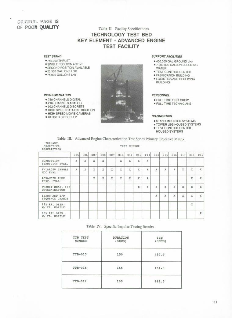
TEST STAND • 750,000 THRUST • SINGLE POSITION ACTIVE • SECOND POSITION AVAILABLE .23,500 GALLONS LOX • 75,000 GALLONS LH2
INSTRUMENTATiON • 750 CHANNELS DIGITAL • 216 CHANNELS ANALOG • 992 CHANNELS DISCRETE • HIGH SPEED DATA DISTRIBUTION • HIGH SPEED MOVIE CAMERAS • CLOSED CIRCUIT TV.
SUPPORT FACILITIES • 450.000 GAL GROUND LH2 • 7,000,000 GALLONS COOLING
WATER • TEST CONTROL CENTER • FABRICATION BUILDING • LOGISTICS AND RECEIVING
BUILDING
PERSONNEL
• FULL TIME TEST CREW • FULL TIME TECHNICIANS
DIAGNOSTICS • STAND MOUNTED SYSTEMS .TOWER LEG HOUSED SYSTEMS 'TEST CONTROL CENTER
HOUSED SYSTEMS
(2.' U'.L PACE IS ( PC)O JALS1 Table II. Facility Specifications.
TECHNOLOGY TEST BED KEY ELEMENT - ADVANCED ENGINE
TEST FACILITY
Table Ill. Advanced Engine Characterization Test Series Primary Objective Matrix. PRIMARY
OBJECTIVE
TEST NUMBER DESCRIPTION
005 006 007 008 009 010 011 012 013 014 015 1 016 017 018 019
COMBUSTION X X X X X X X X STABILITY EVAL.
ENLARGEDTHROAT X X X X X X X X X X X X X X X MCC EVAL.
ADVANCED PUMP X X X X X X X X X PERF. EVAL.
THRUST MEAS. ISP X X X X X X X X DETERMINATION
START AND S/D X X X X X X SEQUENCE CHANGE
88% RPL OPER. X W/ FL. NOZZLE
86% RPL OPER. X W/ FL. NOZZLE
Table IV. Specific Impulse Testing Results.
TTB TEST NUMBER
DURATION (SECS)
Isp (SECS)
TTB-015 150 452.9
TTB-016 165 451.8
TTB-017 160 449.5
111

IGINAL PAGE WHITE PHOTOAPI
IDLEr - OII.z
Fig. 1. SSME Propellant Flow Schematic.
Fig. 2. Aerial Photograph of MSFC Technology Test Bed.
TECHNOLOGY TEST BED DATA ROOK CHRONOLOGY OF EVENTS
TEST TSR 018
TIE) REFERENCE TIME 90 102 2r58O2.789
TOUT OF DAT DELTA(T0)SEF STATE T1BNSET IRESEOCLATORE UNITS
90IO2I2:57:4O.823 -21.9660 OFF P4507561W EXIT 118210001.01W PLUG 71140509 OVEN?
9OIO2:I2:5755.71S -7.0740 08 F93K7574W AUTO SEQUENCE START CEN1WAIID OW
9O:1O2:12:5755.723 -7.0660 ON 79306316 AUTO SEQUFIICE START EVENT
90lO2I2:S755.723 -7.0660 08 793076668 RUN TONE ClOCK EVENT
9Ol02I257:SS.l3I -7.0580 061 742174766 OPEN LOX P000 RWIERCELATDON 0140
90102I257r55.733 -7.0560 OFF 746X71886 1041082 OVSRD RIEW HE FORGE OR ESIE1IE
901O2125755.921 -6.8680 OFU 793175746 AUTO SUGIENCI STARE CCWQSANX 0940
9OIO212r57:56.48I -6.3080 OFF 74207477W LOX POlO RECIRCULATION CLOSED EVENT
9O1E2r123757.341 -5.4480 ON 742074188 LOX 7000 IECORCOJLATION OPEN EVENS
90102:IO57:59.5A7 -3.2420 OFF F42E74916 ENABLE ENGINE LOX CH1LLEOIJII 1310
901102112157159.601 -3.1880 08 79307632W FACILITY 1110180 START TIRED EVENT
90rIO2l2:57r59.6O3 -3.1860 ON P93076746 CABENA SEQUENCE 2 ON EVENT
90:IX2:125759.603 -3.1860 08 703076736 CAMERA SEQUENCE I ON EVENT
9OIO2l2S8 2.313 -0.4760 OFF P93176686 HEN TIME CLOCK EVENT
9O102l21S8r 2.789 0.0000 ON P9307668W BEll TIME CI.00K EVERY
9O:1O2I25N 2.789 0.0000 08 793076336 CADS EIIGLNE START CEN8WWIIT EVENT
90:lO2I2:5R 2.789 0.000 ON P93177286 TINE PULSE OVERRIDE EVENT
Fig. 3. Typical Discrete Event Evaluator Plot PIG 3 ( OO QUALITY
112

Injector Element
Lor Baffle
MCC HGM
Cavities
MCC to z1e Joint
z
Approximate Location -.. of Center of Charge
Faceplate
Fig. 4a. Main Injector.
Cr
Fig. 4b. Main Combustion Chamber.
Engine 0208 Bomb Placement
o i -- Position 2
U Fig. 5.
Stability Rating Bomb
Ablative Shield \ Pin Detonator Spacer Lead Wires
ç Electrostatic Shield Foil
,P <<LL7/V////////X7— Plug Electrostatic
Shield Conductive Paint
Insefl\
Detonator Locking Flat
Wrenching Hex
Approximate cation
I of Center of Charge
-x Fig. 6.
Fig. 7. Bomb Cross-Section.
113

3Press—PSIA
2500 - Hot-Gas Manifold
2000 / G5. 1 (KG2aT) -
1500
500; j 0 --------------- J HDFFP 005 11522.533.544.555.56
Time-Sec
LPOTP
L,'-G7.2(CG 1P)
G3.1 .xç (BG2dT)
MCC Triax#2
HPOTP
• 15 Grain
Fig. 8. Bomb Detonation Matrix.
LPFTP Hot-Gas Manifold
G7 (CG1b)
G3.2(BG2cT)
G5. 2 (KG2bT)
MCCTriax#1-HPOTP HPFTP
Fig. 9. Accelerometer Locations.
2000.0 TTB-5 STAB a MCC IZ-Radial (flPI TAT- (VUflA
1000.0
G
-1000.0
-2000.0 4.97 Time (sec) 5.00
Fig. 10. Pressure Fluctuation Dampening.
1900
1800I
1700-j :
1200 1300 1400 1500 1600 1700
H/POTP Avg Tur Dis Temp (R)
Phase II Modified Engine
Fig. 11. Modified Engine Pump Comparison.
Power Level (%) LPOTP Inlet (NPSP)
!
.]1lO
0 20 40 60 80 100 120 140 160 Time (see)
Power Level -'-- T-10
Fig. 12. Pump Performance Test Profile.
114

- j] I j°j
T1 ii iiii 2
I ,l'i,lrj .j ,
.
, .-II
I.2 •II_2•4
Il ull , ,
.-..-.I . -.-.-- I.. I,
30000 10550 31000 500 12000 32500 13 13500 34000
IBOTP 5000.,, 513.UfI0 Sp..4
I ),00
0000 32000 4000
50.
SUCItON SPUCIFIC STEPS
25-
1.100
1.075-
1.050
3.025-
3000-
0.575
0.550-
0025
Fig. 13. Modified SSME Turbomachinery Performance. Fig. 14. 15 Vane Inducer vs Flight Configuration.
ENHANCED MAIN COMRUSTIgN CHAMBER COOLING
PHASE H MODIFIED SSME o SIGNIFICANT 8LANCHTNG/ CRACKING 50% NONE
PHASE II MCC (FLIGHT) ENLARGED THROAT MCC
Channel Width (CW), in. 0.0400 0.035 Land Width (LW), in. 0.0435 0.045 Wall Thickness (WT), in. 0.028 0.025 Number of Coolant Channels 390 430 Hot Gas Wall Temperature, F 1000 900 MCC Coolant Disch. Temp. (@ 100 % PL), R 466 501
COLD WALL
HOT WALL
Fig. 15. Modified SSME vs Current SSME.
POWER LEVEL - S RPL PUMP INLETS - PSI 320% 180
100%050
80% ,.• ii soc ISO SEC120
E!0 20 40 60 80 100 120 140 lEO
TIME FROM if/S - SECONDS
POWER LEVEL OXIDIZER INLET PRES - FUEL INLET PROS
.NPSP(TANK BOTTOM PRESSURE)
Fig. 16. Advanced Throttling Profile.
115
Recommended