Marine Composites Design Methods for Ship Structures
Webb Ins6tute Senior Elec6ve – Spring 2013 page 0
Marine Composites Webb Ins1tute Senior Elec1ve Spring, 2013
Design Methods for Ship Structures
Eric Greene, Naval Architect [email protected] 410.263.1348 410.703.3025 (cell) hNp://ericgreeneassociates.com/webbins6tute.html
Marine Composites Design Methods for Ship Structures
Webb Ins6tute Senior Elec6ve – Spring 2013 page 1
Composite Ships
The 1tle page from Lloyd’s Register Rules for Composite Ships, 1866
Marine Composites Design Methods for Ship Structures
Webb Ins6tute Senior Elec6ve – Spring 2013 page 2
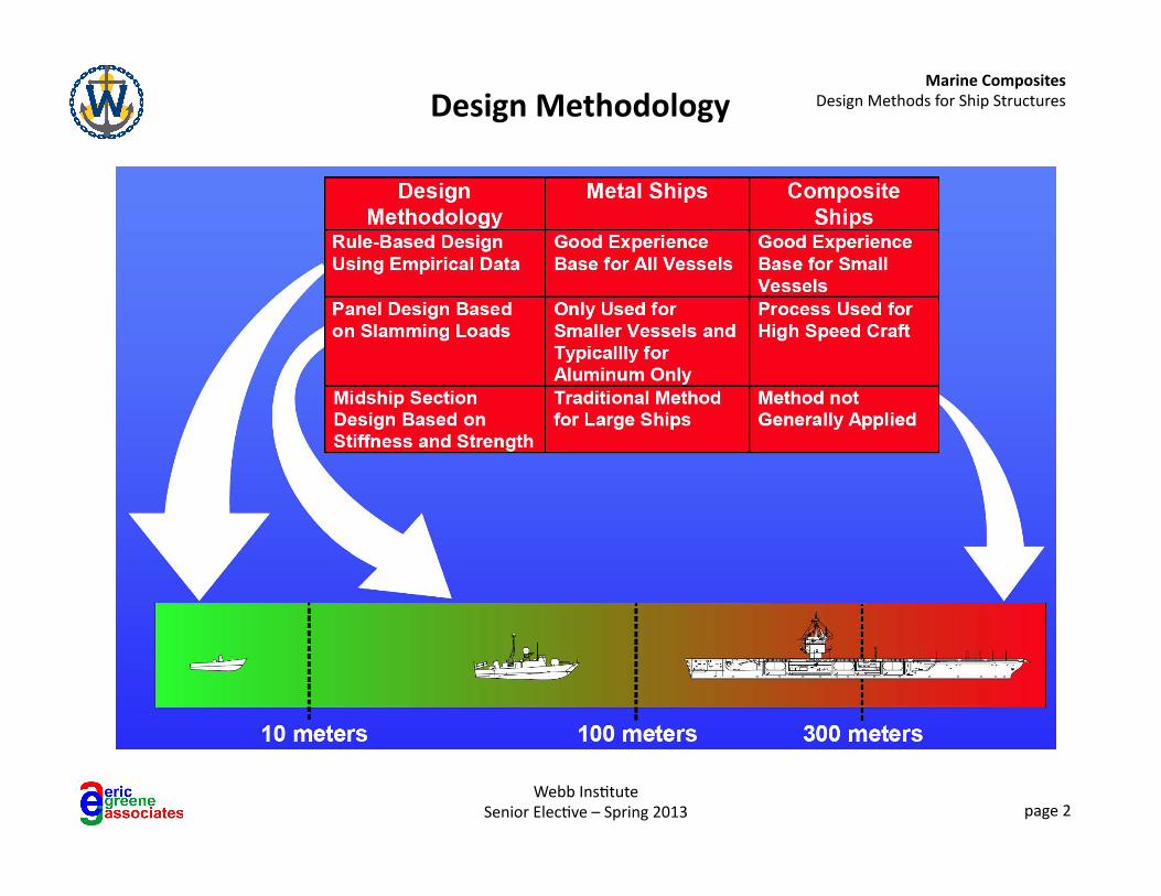
Design Methodology
Marine Composites Design Methods for Ship Structures
Webb Ins6tute Senior Elec6ve – Spring 2013 page 3
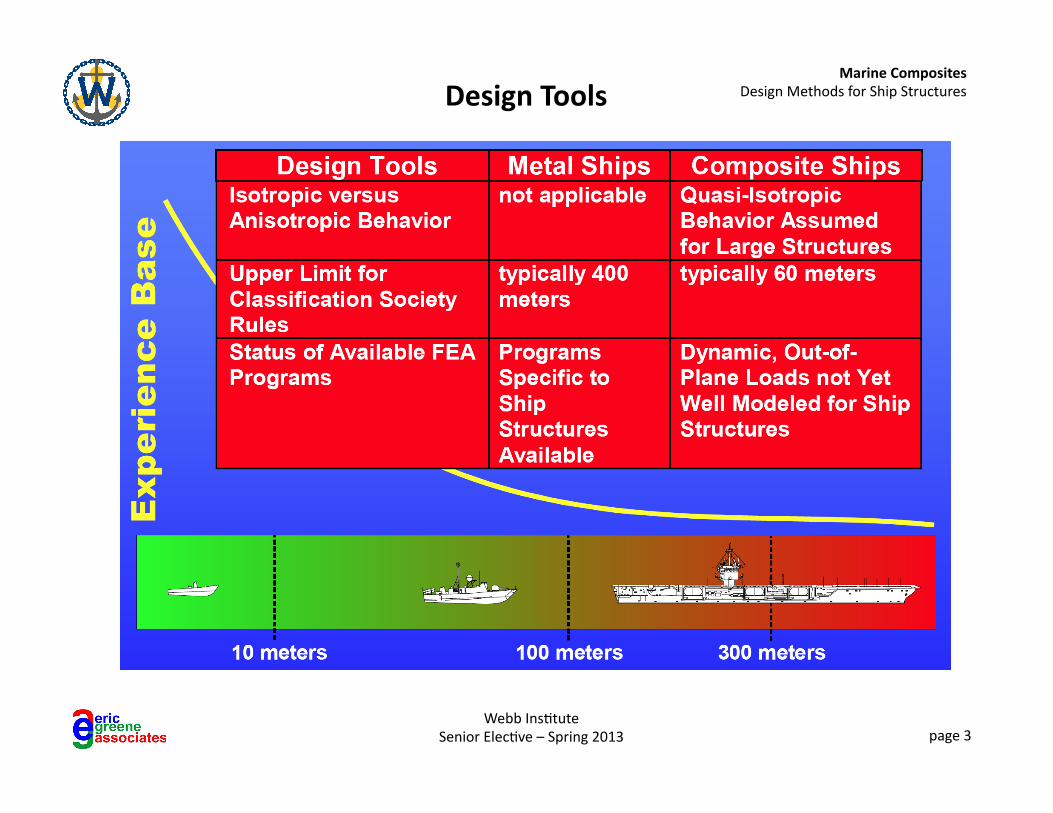
Design Tools
Marine Composites Design Methods for Ship Structures
Webb Ins6tute Senior Elec6ve – Spring 2013 page 4
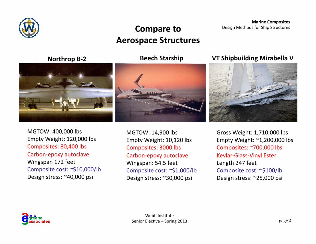
Compare to Aerospace Structures
Northrop B-‐2 Beech Starship VT Shipbuilding Mirabella V
MGTOW: 400,000 lbs Empty Weight: 120,000 lbs Composites: 80,400 lbs Carbon-‐epoxy autoclave Wingspan 172 feet Composite cost: ~$10,000/lb Design stress: ~40,000 psi
MGTOW: 14,900 lbs Empty Weight: 10,120 lbs Composites: 3000 lbs Carbon-‐epoxy autoclave Wingspan: 54.5 feet Composite cost: ~$1,000/lb Design stress: ~30,000 psi
Gross Weight: 1,710,000 lbs Empty Weight: ~1,200,000 lbs Composites: ~700,000 lbs Kevlar-‐Glass-‐Vinyl Ester Length 247 feet Composite cost: ~$100/lb Design stress: ~25,000 psi
Marine Composites Design Methods for Ship Structures
Webb Ins6tute Senior Elec6ve – Spring 2013 page 5
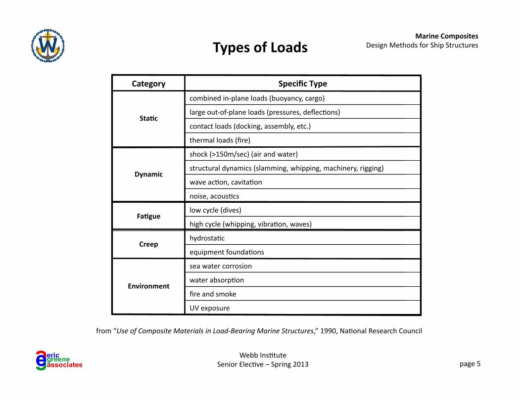
Types of Loads
from “Use of Composite Materials in Load-‐Bearing Marine Structures,” 1990, Na6onal Research Council
UV exposure
fire and smoke
water absorp6on
sea water corrosion
Environment
equipment founda6ons
hydrosta6c Creep
high cycle (whipping, vibra6on, waves)
low cycle (dives) Fa1gue
noise, acous6cs
wave ac6on, cavita6on
structural dynamics (slamming, whipping, machinery, rigging)
shock (>150m/sec) (air and water)
Dynamic
thermal loads (fire)
contact loads (docking, assembly, etc.)
large out-‐of-‐plane loads (pressures, deflec6ons)
combined in-‐plane loads (buoyancy, cargo)
Sta1c
Specific Type Category
Marine Composites Design Methods for Ship Structures
Webb Ins6tute Senior Elec6ve – Spring 2013 page 6
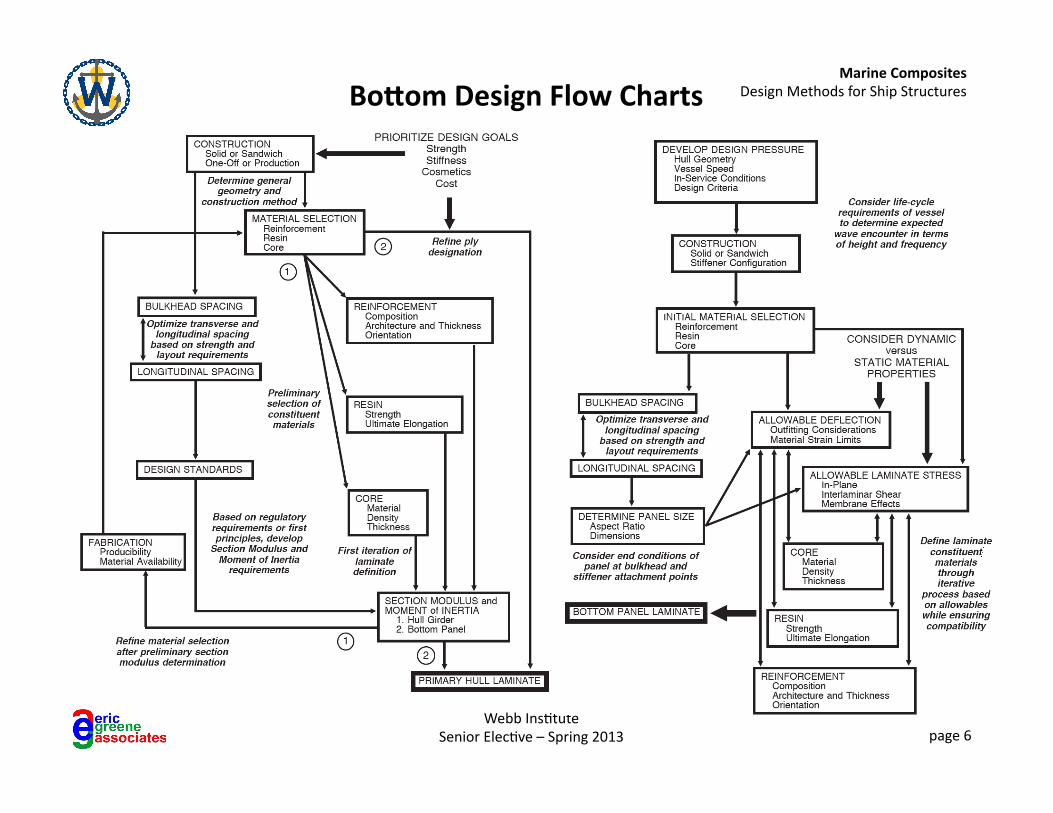
BoPom Design Flow Charts
Marine Composites Design Methods for Ship Structures
Webb Ins6tute Senior Elec6ve – Spring 2013 page 7
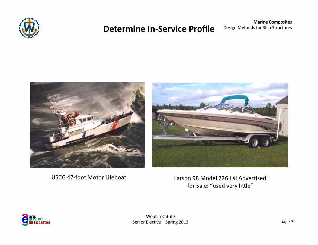
Determine In-‐Service Profile
USCG 47-‐foot Motor Lifeboat Larson 98 Model 226 LXI Adver6sed for Sale: “used very liNle”
Marine Composites Design Methods for Ship Structures
Webb Ins6tute Senior Elec6ve – Spring 2013 page 8
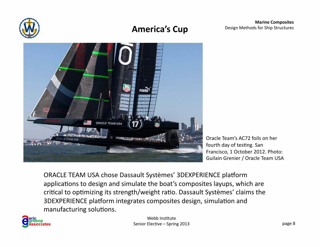
America’s Cup
ORACLE TEAM USA chose Dassault Systèmes’ 3DEXPERIENCE plakorm applica6ons to design and simulate the boat’s composites layups, which are cri6cal to op6mizing its strength/weight ra6o. Dassault Systèmes’ claims the 3DEXPERIENCE plakorm integrates composites design, simula6on and manufacturing solu6ons.
Oracle Team’s AC72 foils on her fourth day of tes6ng. San Francisco, 1 October 2012. Photo: Guilain Grenier / Oracle Team USA
Marine Composites Design Methods for Ship Structures
Webb Ins6tute Senior Elec6ve – Spring 2013 page 9
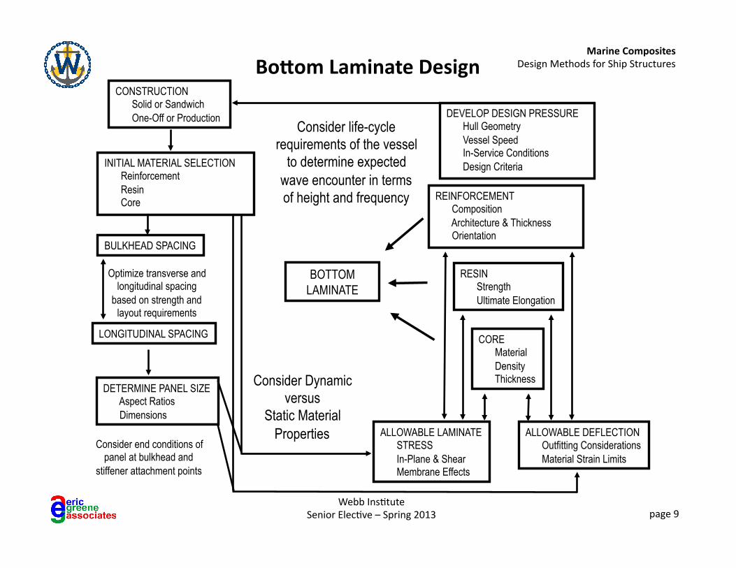
REINFORCEMENT Composition Architecture & Thickness Orientation
RESIN Strength Ultimate Elongation
CORE Material Density Thickness
ALLOWABLE LAMINATE STRESS In-Plane & Shear Membrane Effects
BULKHEAD SPACING
LONGITUDINAL SPACING
Consider end conditions of panel at bulkhead and
stiffener attachment points
Optimize transverse and longitudinal spacing
based on strength and layout requirements
CONSTRUCTION Solid or Sandwich One-Off or Production Consider life-cycle
requirements of the vessel to determine expected
wave encounter in terms of height and frequency
DETERMINE PANEL SIZE Aspect Ratios Dimensions
INITIAL MATERIAL SELECTION Reinforcement Resin Core
ALLOWABLE DEFLECTION Outfitting Considerations Material Strain Limits
Consider Dynamic versus
Static Material Properties
BOTTOM LAMINATE
DEVELOP DESIGN PRESSURE Hull Geometry Vessel Speed In-Service Conditions Design Criteria
BoPom Laminate Design
Marine Composites Design Methods for Ship Structures
Webb Ins6tute Senior Elec6ve – Spring 2013 page 10
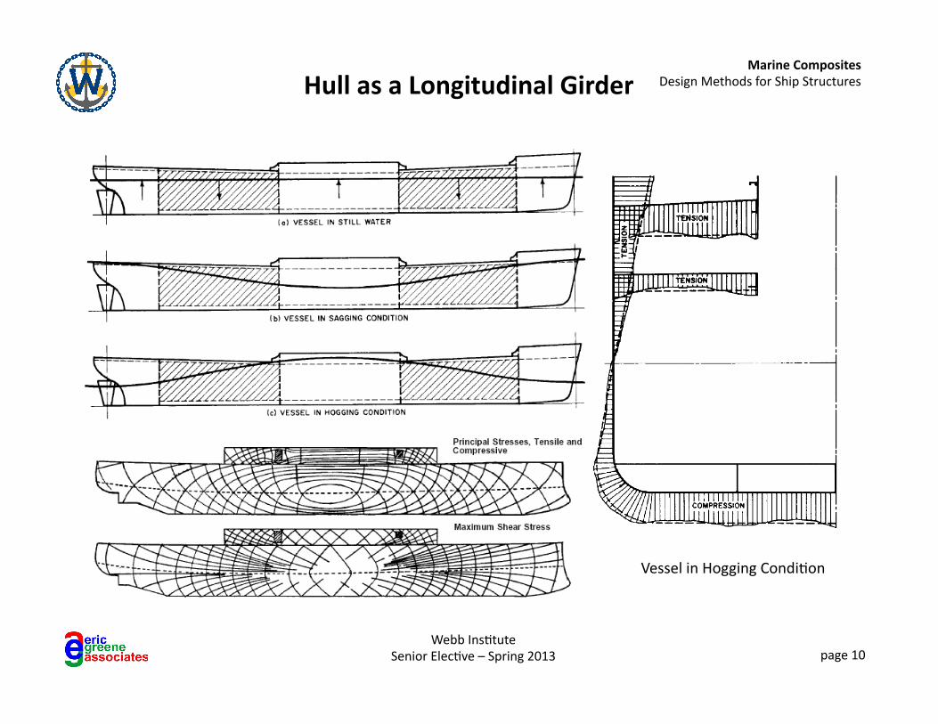
Hull as a Longitudinal Girder
Vessel in Hogging Condi6on
Marine Composites Design Methods for Ship Structures
Webb Ins6tute Senior Elec6ve – Spring 2013 page 11
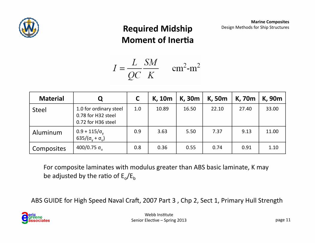
Required Midship Moment of Iner1a
ABS GUIDE for High Speed Naval Crap, 2007 Part 3 , Chp 2, Sect 1, Primary Hull Strength
Material Q C K, 10m K, 30m K, 50m K, 70m K, 90m
Steel 1.0 for ordinary steel 0.78 for H32 steel 0.72 for H36 steel
1.0 10.89 16.50 22.10 27.40 33.00
Aluminum 0.9 + 115/σy 635/(σy + σu)
0.9 3.63 5.50 7.37 9.13 11.00
Composites 400/0.75 σu 0.8 0.36 0.55 0.74 0.91 1.10
For composite laminates with modulus greater than ABS basic laminate, K may be adjusted by the ra6o of Eo/Eb
Marine Composites Design Methods for Ship Structures
Webb Ins6tute Senior Elec6ve – Spring 2013 page 12
Longitudinal Girder Composite Material Concepts
• Cri6cal design considera6on for long, slender hulls • Consider hauling/blocking loads in addi6on to SWBM
• Longitudinal girder s6ffness cri6cal for propulsion shap alignment in power boats and headstay tension for sailboats
• Unidirec6onal reinforcement on the top of longitudinal improves global as well as local strength and s6ffness
• Maximize the use of longitudinal fibers in boNom and deck; use ±45° fibers (double-‐bias) near neutral axis
• Maximize the amount of con6nuous longitudinal reinforcement (without seams) in midship area
Marine Composites Design Methods for Ship Structures
Webb Ins6tute Senior Elec6ve – Spring 2013 page 13
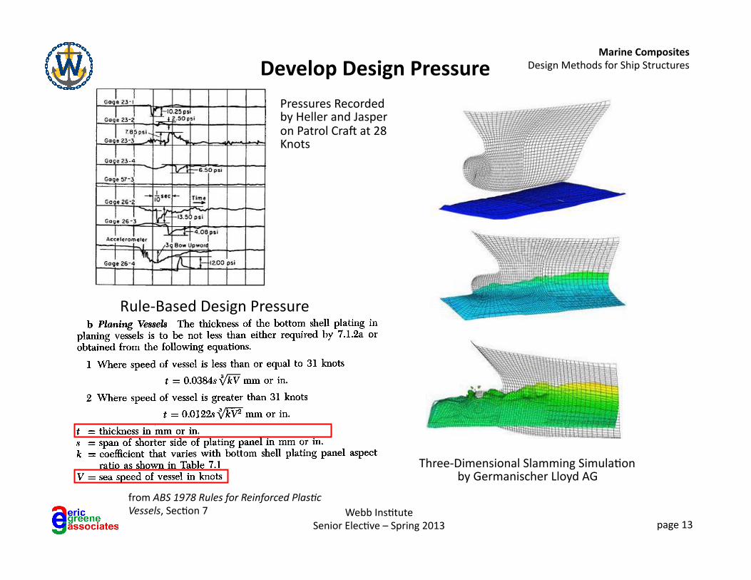
Develop Design Pressure
Three-‐Dimensional Slamming Simula6on by Germanischer Lloyd AG
Pressures Recorded by Heller and Jasper on Patrol Crap at 28 Knots
from ABS 1978 Rules for Reinforced Plas@c Vessels, Sec6on 7
Rule-‐Based Design Pressure
Marine Composites Design Methods for Ship Structures
Webb Ins6tute Senior Elec6ve – Spring 2013 page 14
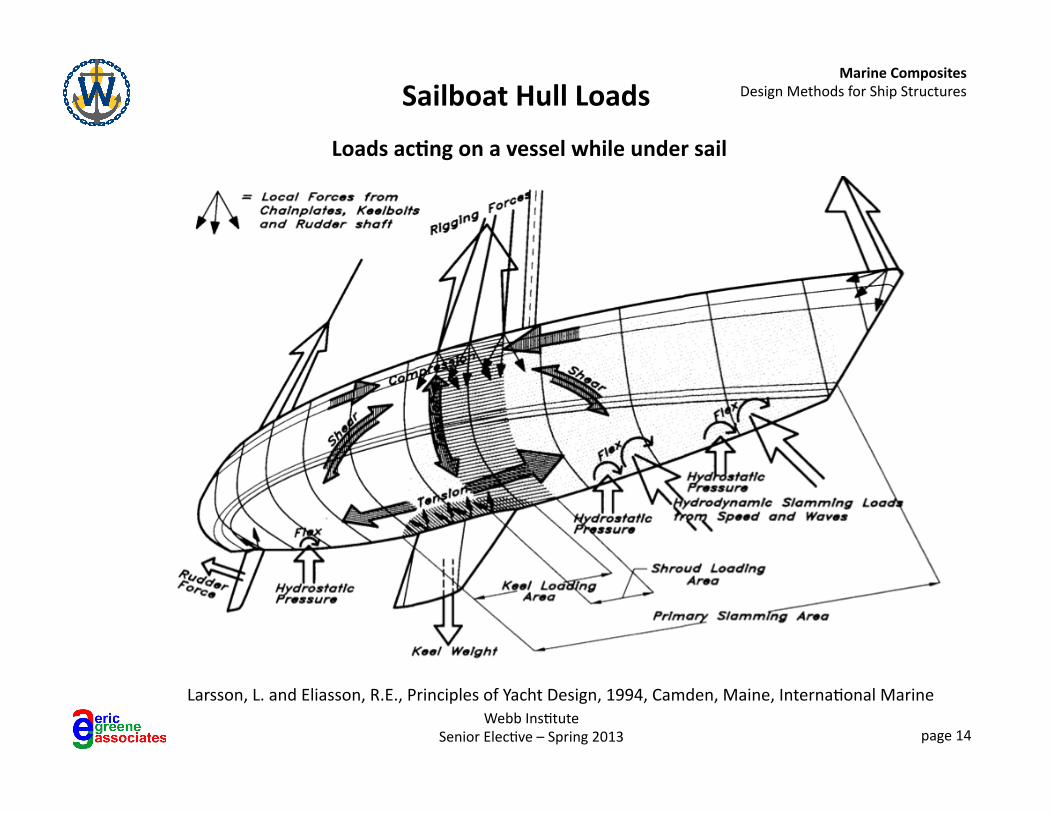
Sailboat Hull Loads
Loads ac1ng on a vessel while under sail
Larsson, L. and Eliasson, R.E., Principles of Yacht Design, 1994, Camden, Maine, Interna6onal Marine
Marine Composites Design Methods for Ship Structures
Webb Ins6tute Senior Elec6ve – Spring 2013 page 15
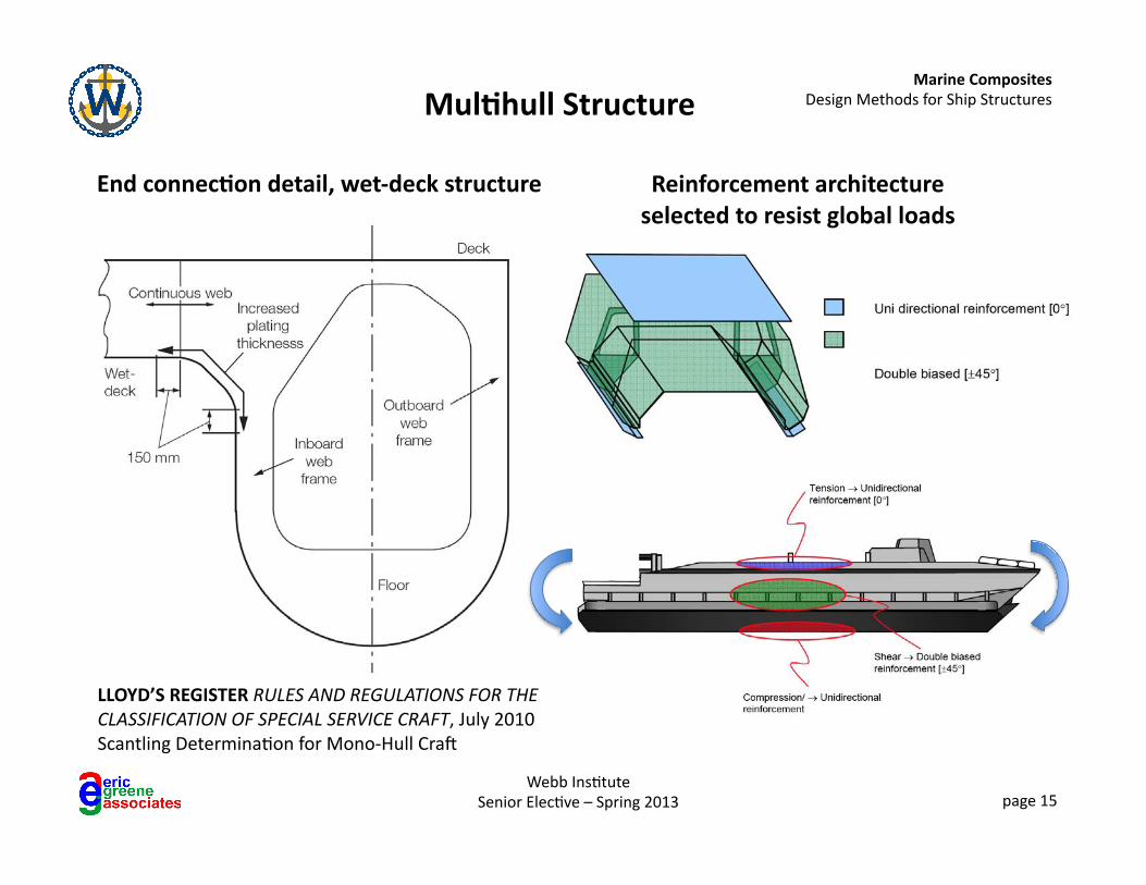
Mul1hull Structure
LLOYD’S REGISTER RULES AND REGULATIONS FOR THE CLASSIFICATION OF SPECIAL SERVICE CRAFT, July 2010 Scantling Determina6on for Mono-‐Hull Crap
End connec1on detail, wet-‐deck structure Reinforcement architecture selected to resist global loads
Marine Composites Design Methods for Ship Structures
Webb Ins6tute Senior Elec6ve – Spring 2013 page 16
Mul1hull and Surface Effect Ship Considera1ons
• Torsional loads may be design-‐limi6ng for mul6hulls, SESs, and vessels with large deck openings
• ±45° fibers (double-‐bias) or unidirec6onals aligned ±45° can be effec6ve to resist torsional loads
• Ensure that ±45° fibers are con6nuous, minimizing buN joints
• For catamarans, the design transverse bending moment must be calculated to determine the load ac6ng on the cross structure connec6ng the hulls
• Termina6on of mul6hull transverse structure at the main hulls is a cri6cal design element
Marine Composites Design Methods for Ship Structures
Webb Ins6tute Senior Elec6ve – Spring 2013 page 17
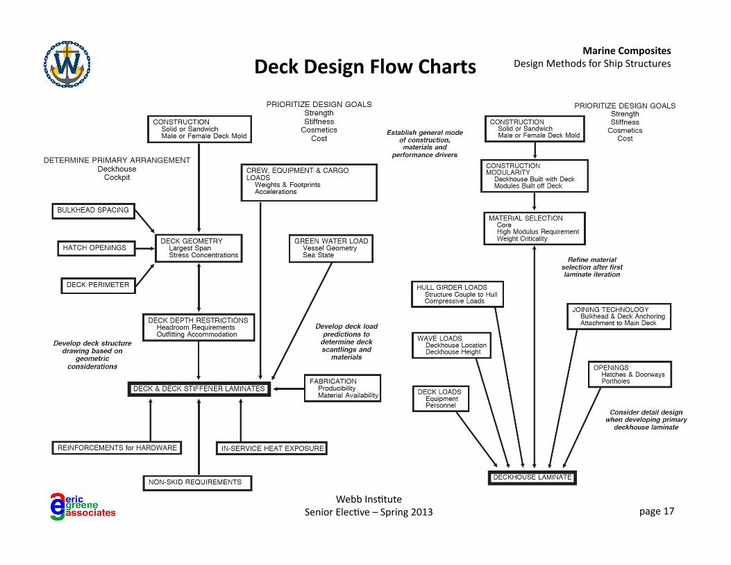
Deck Design Flow Charts
Marine Composites Design Methods for Ship Structures
Webb Ins6tute Senior Elec6ve – Spring 2013 page 18
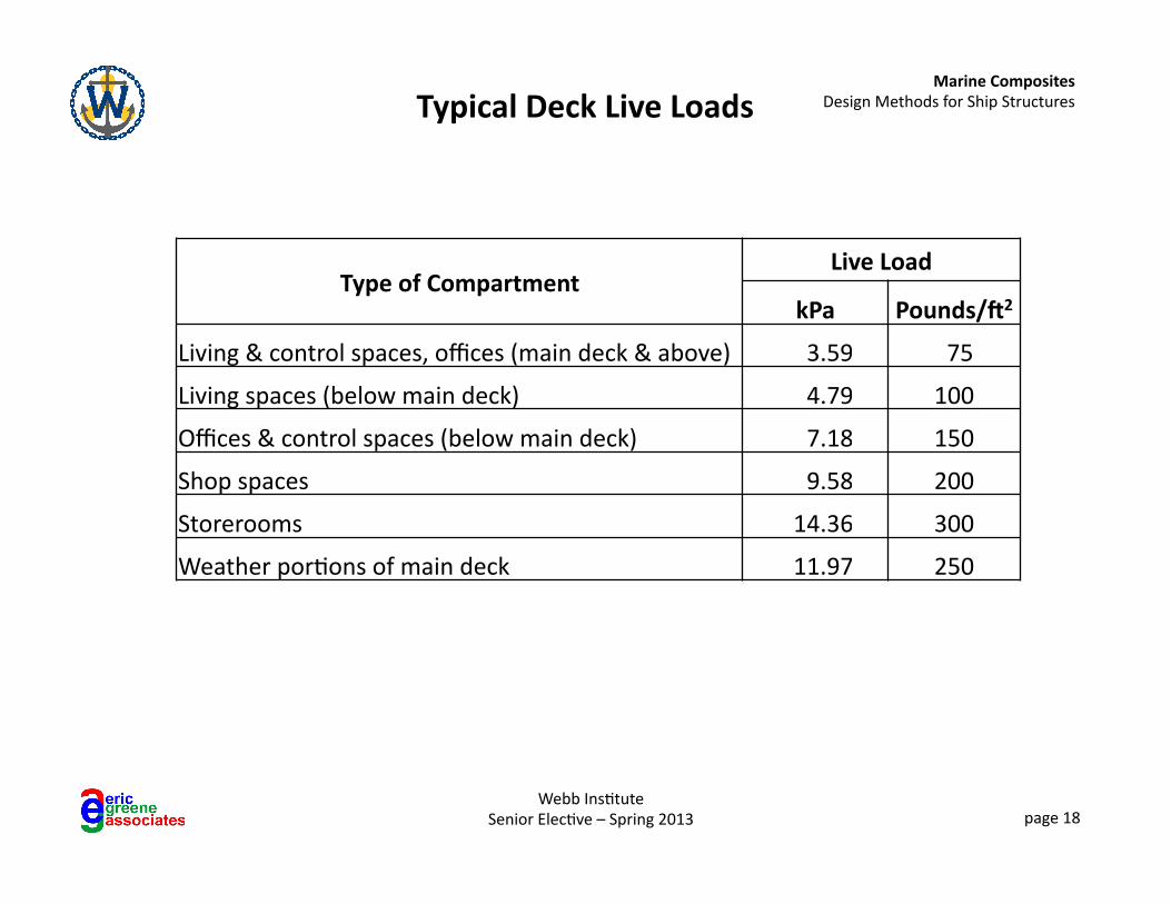
Typical Deck Live Loads
Type of Compartment Live Load
kPa Pounds/`2
Living & control spaces, offices (main deck & above) 3.59 75
Living spaces (below main deck) 4.79 100
Offices & control spaces (below main deck) 7.18 150
Shop spaces 9.58 200
Storerooms 14.36 300
Weather por6ons of main deck 11.97 250
Marine Composites Design Methods for Ship Structures
Webb Ins6tute Senior Elec6ve – Spring 2013 page 19
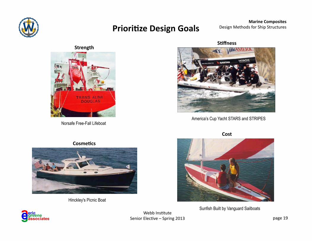
Priori1ze Design Goals
Norsafe Free-Fall Lifeboat
Strength S1ffness
America’s Cup Yacht STARS and STRIPES
Cosme1cs
Hinckley's Picnic Boat
Cost
Sunfish Built by Vanguard Sailboats
Marine Composites Design Methods for Ship Structures
Webb Ins6tute Senior Elec6ve – Spring 2013 page 20
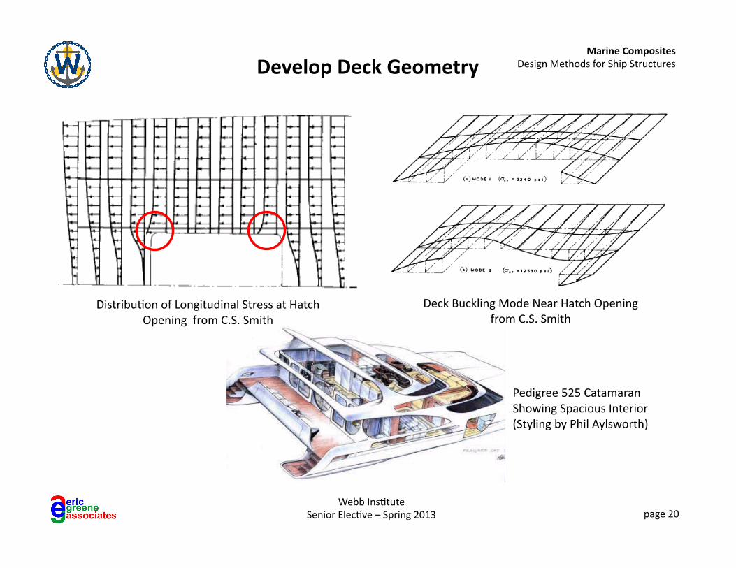
Develop Deck Geometry
Distribu6on of Longitudinal Stress at Hatch Opening from C.S. Smith
Deck Buckling Mode Near Hatch Opening from C.S. Smith
Pedigree 525 Catamaran Showing Spacious Interior (Styling by Phil Aylsworth)
Marine Composites Design Methods for Ship Structures
Webb Ins6tute Senior Elec6ve – Spring 2013 page 21
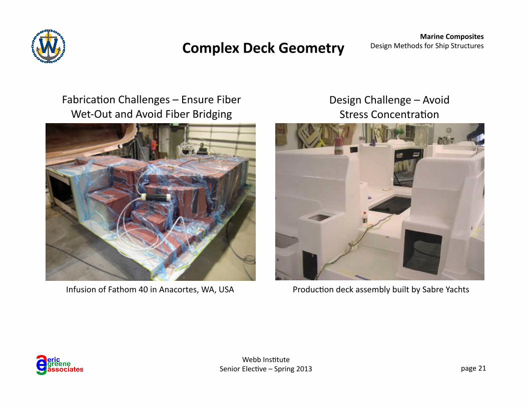
Complex Deck Geometry
Produc6on deck assembly built by Sabre Yachts Infusion of Fathom 40 in Anacortes, WA, USA
Fabrica6on Challenges – Ensure Fiber Wet-‐Out and Avoid Fiber Bridging
Design Challenge – Avoid Stress Concentra6on
Marine Composites Design Methods for Ship Structures
Webb Ins6tute Senior Elec6ve – Spring 2013 page 22
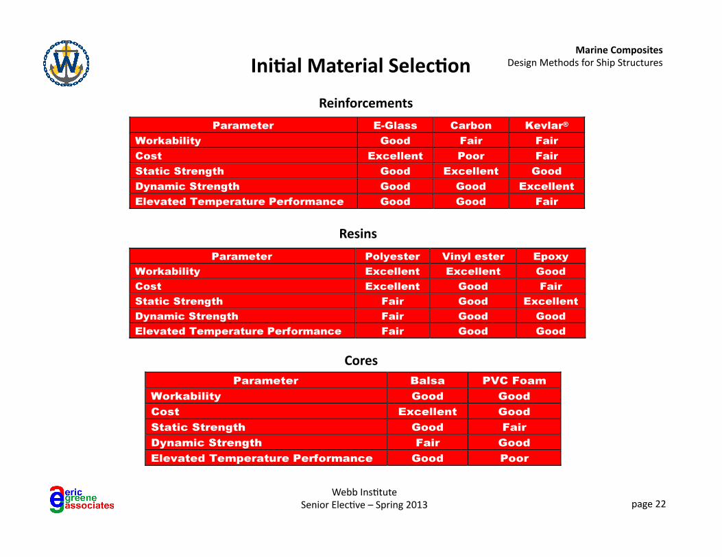
Ini1al Material Selec1on
Reinforcements
Resins
Cores
Marine Composites Design Methods for Ship Structures
Webb Ins6tute Senior Elec6ve – Spring 2013 page 23
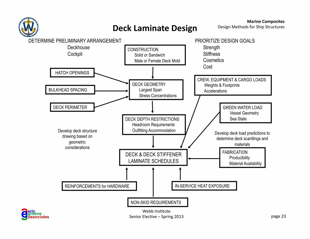
Deck Laminate Design PRIORITIZE DESIGN GOALS
Strength Stiffness Cosmetics Cost
DECK GEOMETRY Largest Span Stress Concentrations
GREEN WATER LOAD Vessel Geometry Sea State
FABRICATION Producibility Material Availability
DECK DEPTH RESTRICTIONS Headroom Requirements Outfitting Accommodation
BULKHEAD SPACING
DECK PERIMETER
Develop deck structure drawing based on
geometric considerations
CONSTRUCTION Solid or Sandwich Male or Female Deck Mold
DETERMINE PRELIMINARY ARRANGEMENT Deckhouse Cockpit
REINFORCEMENTS for HARDWARE
HATCH OPENINGS
NON-SKID REQUIREMENTS
DECK & DECK STIFFENER LAMINATE SCHEDULES
Develop deck load predictions to determine deck scantlings and
materials
IN-SERVICE HEAT EXPOSURE
CREW, EQUIPMENT & CARGO LOADS Weights & Footprints Accelerations
Marine Composites Design Methods for Ship Structures
Webb Ins6tute Senior Elec6ve – Spring 2013 page 24
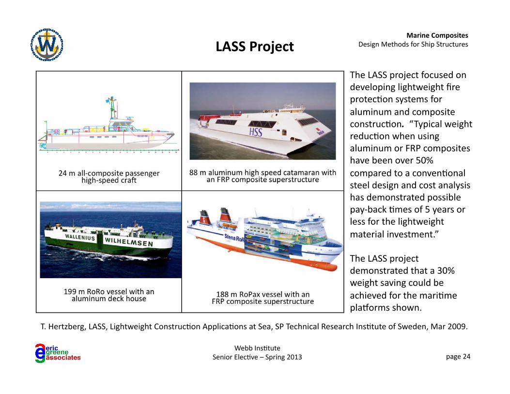
LASS Project
T. Hertzberg, LASS, Lightweight Construc6on Applica6ons at Sea, SP Technical Research Ins6tute of Sweden, Mar 2009.
The LASS project focused on developing lightweight fire protec6on systems for aluminum and composite construc6on. “Typical weight reduc6on when using aluminum or FRP composites have been over 50% compared to a conven6onal steel design and cost analysis has demonstrated possible pay-‐back 6mes of 5 years or less for the lightweight material investment.”
The LASS project demonstrated that a 30% weight saving could be achieved for the mari6me plakorms shown.
Marine Composites Design Methods for Ship Structures
Webb Ins6tute Senior Elec6ve – Spring 2013 page 25
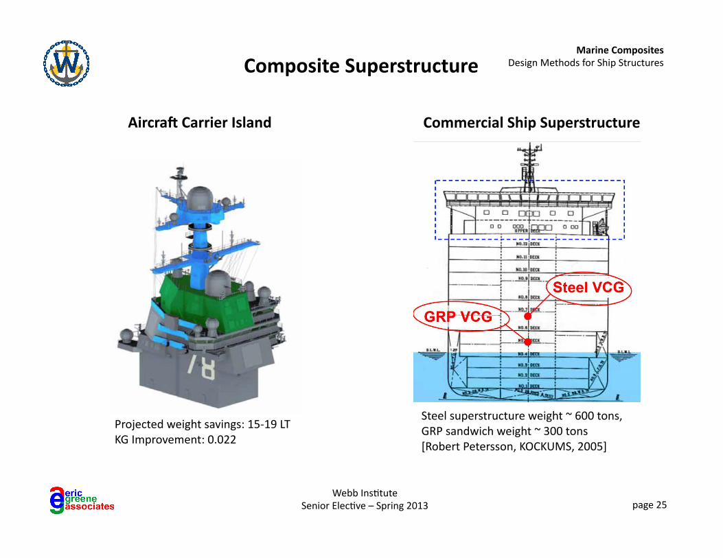
Composite Superstructure
Steel superstructure weight ~ 600 tons, GRP sandwich weight ~ 300 tons [Robert Petersson, KOCKUMS, 2005]
Commercial Ship Superstructure
Projected weight savings: 15-‐19 LT KG Improvement: 0.022
Aircra` Carrier Island
Marine Composites Design Methods for Ship Structures
Webb Ins6tute Senior Elec6ve – Spring 2013 page 26
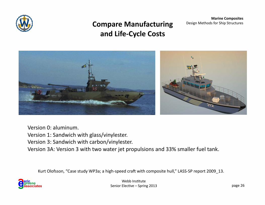
Compare Manufacturing and Life-‐Cycle Costs
Version 0: aluminum. Version 1: Sandwich with glass/vinylester. Version 3: Sandwich with carbon/vinylester. Version 3A: Version 3 with two water jet propulsions and 33% smaller fuel tank.
Kurt Olofsson, “Case study WP3a; a high-‐speed crap with composite hull,” LASS-‐SP report 2009_13.
Marine Composites Design Methods for Ship Structures
Webb Ins6tute Senior Elec6ve – Spring 2013 page 27
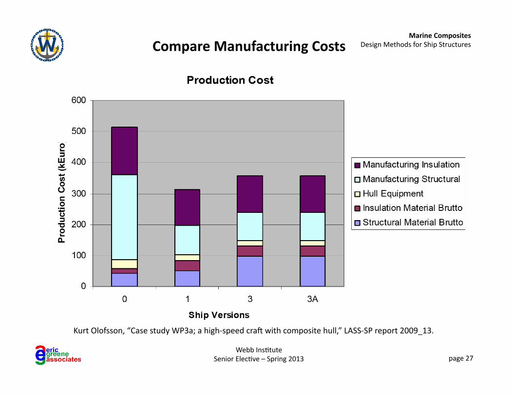
Compare Manufacturing Costs
Kurt Olofsson, “Case study WP3a; a high-‐speed crap with composite hull,” LASS-‐SP report 2009_13.
Marine Composites Design Methods for Ship Structures
Webb Ins6tute Senior Elec6ve – Spring 2013 page 28
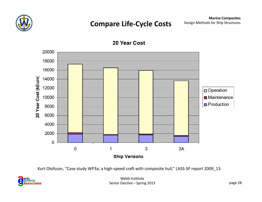
Compare Life-‐Cycle Costs
Kurt Olofsson, “Case study WP3a; a high-‐speed crap with composite hull,” LASS-‐SP report 2009_13.
Marine Composites Design Methods for Ship Structures
Webb Ins6tute Senior Elec6ve – Spring 2013 page 29
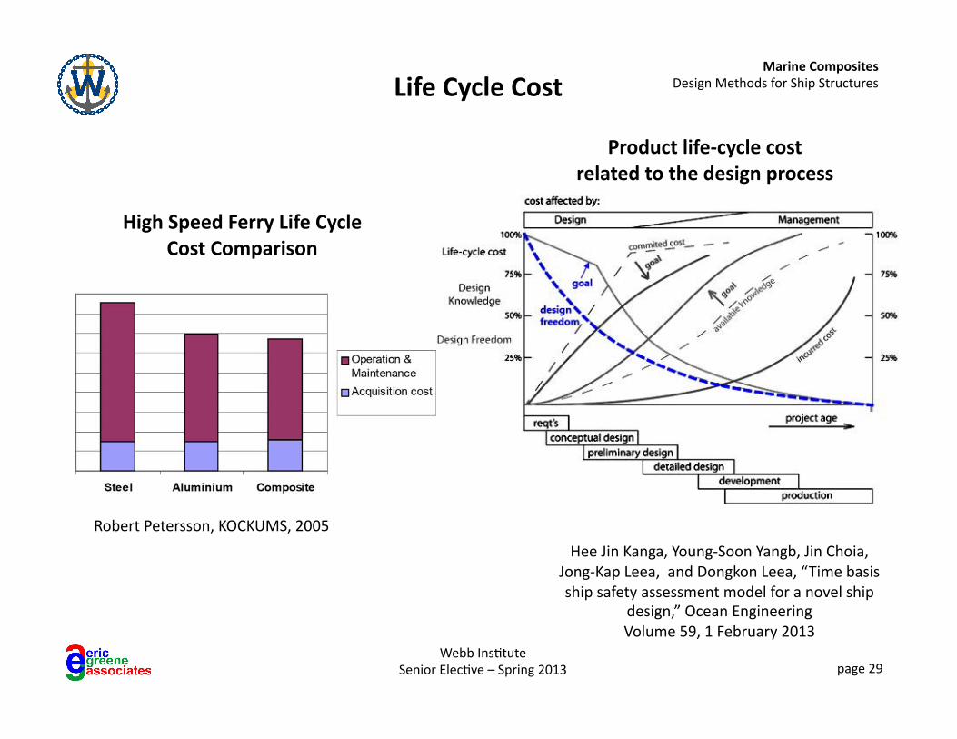
Life Cycle Cost
High Speed Ferry Life Cycle Cost Comparison
Robert Petersson, KOCKUMS, 2005
Product life-‐cycle cost related to the design process
Hee Jin Kanga, Young-‐Soon Yangb, Jin Choia, Jong-‐Kap Leea, and Dongkon Leea, “Time basis ship safety assessment model for a novel ship
design,” Ocean Engineering Volume 59, 1 February 2013
Marine Composites Design Methods for Ship Structures
Webb Ins6tute Senior Elec6ve – Spring 2013 page 30
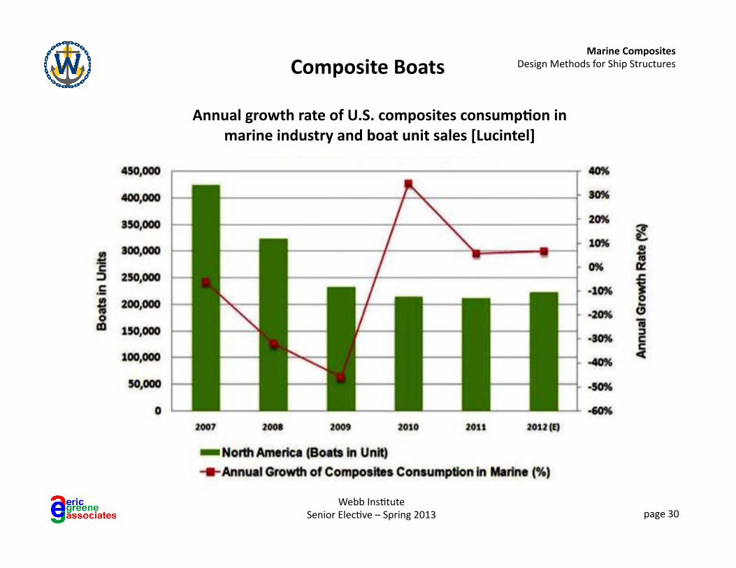
Annual growth rate of U.S. composites consump1on in marine industry and boat unit sales [Lucintel]
Composite Boats
Recommended