1
GRIPNAIL MODEL 7005 AUTOMATIC PIN WELDER
POWER PINNER 7005
OPERATOR’S MANUAL
Copyright: November 23, 2004 Revised: 5-09-08
Serial No. 04110126 - .

2
GRIPNAIL MODEL 7005 AUTOMATIC PIN WELDER
TABLE OF CONTENTS
INTRODUCTION …………………………………………………….…………….3 OPERATOR SAFETY……………………………………………………………....3 SYSTEM REQUIREMENTS………………………………………………………..4 INSTALLATION INSTRUCTIONS ……………………………………………..4-5 MAINTENANCE………………………………………………………………….…5 TROUBLESHOOTING………………………………………………………………6 SYSTEM OPERATIONS/ COMPONENT IDENTIFICATION WELD SETTING ADJUSTMENTS………………………………...7 DRIVE HEAD ASSEMBLY…………………………………………8 LOAD CYLINDER ASSEMBLY………………………………...9-10 PROXIMITY SENSOR……………………………………………...10 ELECTRICAL ASSEMBLY………………………………………...11 CONTROL ENCLOSURE………………………………….………..12 DRIVE AND LOAD VALVES………………………………………13 PRESSURE REGULATOR…………………………………………..14 FOOT PEDAL………………………………………………………...15 ELECTRICAL SCHEMATIC ……………………………………16–17 PNEUMATIC DIAGRAM …………………………………………..18 PARTS LIST …………………………………………………………………………19 SERVICE POLICY …………………………………………………………………..20 WARRANTY………………………………………………………………………....21

3
GRIPNAIL MODEL 7005 AUTOMATIC PIN WELDER
INTRODUCTION
The Gripnail 7005 automatic pin welding machine was designed to require minimum maintenance. It has evolved from the previous models; taking all of the best features and addressing the customers’ issue of adjustments and maintenance. This model uses a proximity sensor to detect the transfer block location. The sensor is connected to quick disconnect cables that indicate the sensor’s operating state. This feature saves valuable time if troubleshooting is necessary. All hose connections between valves and cylinders use push-fit type fittings. These fittings save maintenance time if lubrication or replace-ment is required on any item.
OPERATOR SAFETY Proper safety precautions must be observed with any piece of equipment. This section contains several guidelines designed to ensure operator safety. Follow these directions at all times.
REMEMBER—SAFETY FIRST!
FIVE SAFETY RULES 1. DO NOT OPERATE this machine without all covers and guards in place. 2. DISCONNECT all electrical power and compressed air sources before servicing.
Follow OSHA standard 1910.147 “CONTROL of HAZARDOUS ENERGY (LOCKOUT/TAGOUT)”
3. TROUBLESHOOTING should be done by qualified personnel only. 4. THE OPERATOR should always wear the personal protective equipment as out-
lined by his/her employer, such as eye and ear protection, to avoid injury. 5. MAINTAIN the equipment in good operating condition.

4
GRIPNAIL MODEL 7005 AUTOMATIC PIN WELDER
SYSTEM REQUIREMENTS ELECTRICAL: 190, 208, 230 VAC/60 HZ/1Ø 31.0, 28.4, 25.5 AMPS (Recommend using a 50 Amp, slow blow Disconnect) PNEUMATIC: 40-55 PSI @ 1 CFM
INSTALLATION INSTRUCTIONS 1. Place machine on a hard, flat, level surface. If the surface is irregular and shimming is required, use steel (sheet metal) to make shims. Normal vibratory parts feeder operation requires the machine to be stable and solidly supported. DO NOT USE cardboard, ply- wood, particle board, other composite wood products or soft materials as shim stock. 2. Place bowl feeder on machine into spaces provided, noting location of bowl exit. Wire
the bowl feeder to Wires 2, 5 & GND located in the Junction Box on the top of the ma-chine. (See Figure 1)
3. Ensure a 1/8 inch clearance gap exists between the feeder bowl exit and the entrance to the track assembly. 4. Attach the 1/4 inch wing nut and washer to the 2-1/2 inch screw to retain the lower guard. 5. Install the front guard using the four (4) 1/4 inch truss head screws provided. 6. Connect air. Safety Note: Quick disconnect air fittings are recommended.
ALWAYS install the free flowing MALE connector onto the machine. This will permit immediate exhausting of air from the machine when disconnected from the shop supply.
7. Connect electricity to the disconnect switch located inside the Electrical Enclosure on the
door. (See Figure 2) Measure the voltage at the customer supplied fused disconnect. Set the jumper on the terminal strip (190, 208 or 230) to match the incoming voltage.
Figure 1 Figure 2

5
GRIPNAIL MODEL 7005 AUTOMATIC PIN WELDER
MAINTENANCE 1. DRAIN water from filter/regulator assembly DAILY. 2. REMOVE accumulated fiberglass and adhesive buildup from the magnetic driver and track daily or as required. 3. Check for loose hardware and tighten as required.
SEQUENCE OF OPERATION 1. Input 2 (Load Sensor) AND Input 3 OR 4 OR B OR C OR D MUST be on. 2. Input 1 (Foot or Trigger) is activated momentarily or continuously held. 3. Output 2 (Drive) turns on. 4. Output 3 (Weld Relay) turns on and stays on based on the time setting from Input 3-D. 5. Output 3 (Weld Relay) turns off. 6. Output 2 (Drive) turns off. 7. Output 1 (Load) turns on. 8. Input 2 (Load Sensor) turns off. 9. Output 1 (Load) turns off. 10. Input 2 (Load Sensor) turns on. 11. Input 1 (Foot or Trigger) must be off after Step 9 to restart the sequence (if RAPID FIRE
off).
INPUT 3-D (C ON) INPUT E (ON) WELD SETTING NO WELD –4 RAPID FIRE INPUT 2 (ON) LOAD SENSOR INPUT 1 TRIGGER
PLC INPUTS & OUTPUTS
OUTPUT 1 OUTPUT 3 LOAD VALVE OUTPUT 2 WELD RELAY DRIVE VALVE

6
GRIPNAIL MODEL 7005 AUTOMATIC PIN WELDER
TROUBLESHOOTING
A. Drive head doesn’t operate after foot pedal is depressed.
1. Check incoming power connection and ON switch. Page 12. 2. Is air connection and/or shop supply valve open? 3. Is the load proximity sensor indicator lights ON? Page 10.
a. If not ON, check for loose cable connections or components. b. If not ON, check 24 Volt DC power supply in control box. Page 11.
4. Check drive valve fuse #3. 5. Is the foot pedal input light (I1) and drive valve output light (O2) ON when the foot pedal is depressed. Page 11. 6. Check internal connections in foot pedal and external cable condition. Page 15.
B. New weld pins do not load onto drive head.
1. Check the drive cylinder and magnetic driver. If either is discovered loose, readjust and tighten. See page 8. 2. Check load valve fuse #4.
3. Turn OFF all power and air, then manually check load cylinder for binding.
C. Vibratory feeder bowl doesn’t operate.
1. Check the position of the speed control setting. 2. Check the sensor on track. 3. Check the feeder bowl control fuse (3 amp). Page 11.
D. Improper weld.
1. Adjust weld setting. Page 12. 2. Clean upper and lower weld tips. 3. Check the weld transformer is set on the correct taps to match incoming voltage.

7
GRIPNAIL MODEL 7005 AUTOMATIC PIN WELDER
WELD SETTING ADJUSTMENTS
1. With the power “ON’, set the WELD SETTING switch to correspond to the pin being fas-tened. (Note: These setting are reference starting points only.)
PIN SETTING 57 1 107 1-2 127 2 137 2-3 157 3 207 4 2. Place the sheet metal flat on the lower electrode and press the foot pedal. 3. Make several test welds to insure uniform and proper welds.
4. The WELD SETTING switch also has a NO WELD position. This disables the weld circuit to test functions of the rest of the machine cycle.

8
GRIPNAIL MODEL 7005 AUTOMATIC PIN WELDER
ELBOW P/N 46211 WITH RESTRICTOR P/N 31293
SCREW 1/4”-20x 1-1/4” P/N 60161
4” HEX STANDOFF P/N 42467
GUIDE BUSS ROD P/N 30961
UPPER WELD TIP P/N 31011
DRIVE HEAD ASSEMBLY
SCREW 1/4-20 x 2.5” P/N 60142
SCREW 1/4-20 X 2” P/N 60112
TUBING, 3/8” P/N 48036
DRIVE CYLINDER P/N 44267 CYLINDER FOOT BRACKET P/N 40222
DRIVE HEAD BRACKET P/N 30733
HEX BOLT 5/16-18 x 2.5” P/N 60413 5/16 FLAT WASHER P/N 61109 ESN NUT 5/16-18 P/N 62009
ROD GUIDE P/N 31050
TRACK ASSEMBLY P/N 20384
PROX SENSOR P/N 51262
INSULATOR TIP P/N 31051
REPLACEMENT WELD CABLE ASSEMBLY P/N 20409
3/8-16X1-1/4 HHCS P/N 60046 3/8 LOCKWASHER P/N 61201 3/8 FLAT WASHER P/N 61109 3/8-16 HEX NUT P/N 62109
5/16X18X1-1/4 SHCS P/N 65175 5/16 LOCKWASHER P/N 61205

9
GRIPNAIL MODEL 7005 AUTOMATIC PIN WELDER
LOAD CYLINDER ASSEMBLY
CYLINDER SPACER BLOCK P/N 31049
LOAD CYLINDER P/N 44257
TRANSFER BLOCK P/N 20364
JAM NUT 1/4”-28 P/N 62202
LOAD CYLINDER PLATE P/N 30126
FRONT GUARD P/N 31038 NOT SHOWN
1/4” TUBE P/N 48025
PROXIMITY SENSOR P/N 51268 PROXIMITY SENSOR CABLE
P/N 51269
Position the Transfer Block so this point intrudes on the Pin path by approximately 1/32”. Rotate the Transfer Block to horizontal, to assure the top key section equally engages the bottom of the Track .

10
GRIPNAIL MODEL 7005 AUTOMATIC PIN WELDER
The sensor cables, shown below, contain two (2) light emitting diodes (LED’s). The GREEN indicates the power is ON. The YELLOW indicates the sensor is activated by its target. This will help troubleshooting in the event a miss adjustment or other service requirement.
GREEN LED
YELLOW LED
LOAD RETURN SENSOR
The transfer block fits into the track for easy alignment.
ELECTRODE NUT P/N 31278
LOWER WELD TIP P/N 31032
11
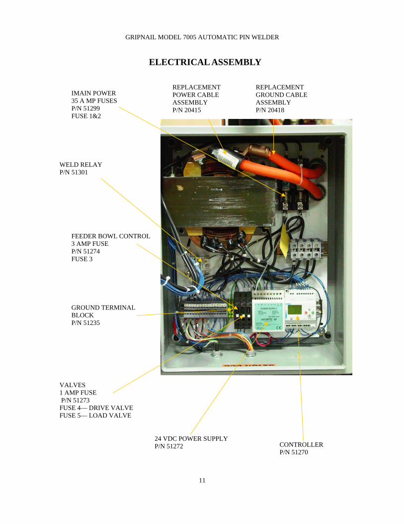
GRIPNAIL MODEL 7005 AUTOMATIC PIN WELDER
ELECTRICAL ASSEMBLY
24 VDC POWER SUPPLY P/N 51272
IMAIN POWER 35 A MP FUSES P/N 51299 FUSE 1&2
FEEDER BOWL CONTROL 3 AMP FUSE P/N 51274 FUSE 3
VALVES 1 AMP FUSE P/N 51273 FUSE 4— DRIVE VALVE FUSE 5— LOAD VALVE
CONTROLLER P/N 51270
GROUND TERMINAL BLOCK P/N 51235
REPLACEMENT POWER CABLE ASSEMBLY P/N 20415
REPLACEMENT GROUND CABLE ASSEMBLY P/N 20418
WELD RELAY P/N 51301
12
GRIPNAIL MODEL 7005 AUTOMATIC PIN WELDER
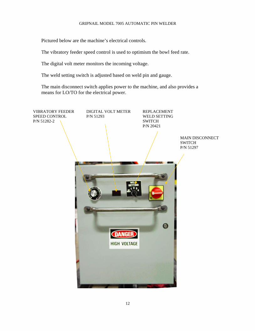
Pictured below are the machine’s electrical controls. The vibratory feeder speed control is used to optimism the bowl feed rate. The digital volt meter monitors the incoming voltage. The weld setting switch is adjusted based on weld pin and gauge. The main disconnect switch applies power to the machine, and also provides a means for LO/TO for the electrical power.
VIBRATORY FEEDER SPEED CONTROL P/N 51282-2
DIGITAL VOLT METER P/N 51293
REPLACEMENT WELD SETTING SWITCH P/N 20421
MAIN DISCONNECT SWITCH P/N 51297

13
GRIPNAIL MODEL 7005 AUTOMATIC PIN WELDER
DRIVE VALVE P/N 44240 CORD SET P/N 51227
LOAD VALVE P/N 44251 CORD SET P/N 51227
ELBOW 3/8 TUBE x 1/4 NPT P/N 46211
ELBOW 1/4 TUBE x 1/8 NPT P/N 46209
DRIVE and LOAD VALVES
3/8” TUBING P/N 48036
1/4” TUBING P/N 48025

14
GRIPNAIL MODEL 7005 AUTOMATIC PIN WELDER
PRESSURE REGULATOR
FILTER/ REGULATOR P/N 40206
BRACKET W/ NUT P/N 42445
REGULATOR GAGE P/N 44120
TEE FITTING P/N 46262

15
GRIPNAIL MODEL 7005 AUTOMATIC PIN WELDER
FOOT PEDAL
NOTE: RELEASE pedal completely after each cycle. Both air and electrical power must be on to operate foot pedal.
FOOT PEDAL INTERNAL CONNECTIONS USE NORMALLY OPEN TERMINALS
TERMINAL CONNECTIONS
FOOT PEDAL P/N 51264
GROUND WIRE

16
GRIPNAIL MODEL 7005 AUTOMATIC PIN WELDER
ELECTRICAL SCHEMATIC

17
GRIPNAIL MODEL 7005 AUTOMATIC PIN WELDER
ELECTRICAL SCHEMATIC

18
GRIPNAIL MODEL 7005 AUTOMATIC PIN WELDER
PNEUMATIC DIAGRAM

19
GRIPNAIL MODEL 7005 AUTOMATIC PIN WELDER
ITEM# PART# DESCRIPTION QTY (EA OR FT) 1 31247 Load cylinder & sensor guard 1 2 62016 Nut, wing 1/4”-20 3 3 31038 Front guard 1 4 31278 Electrode nut 1 5 31032 Lower Weld Tip 1 6 31011 Upper Weld Tip 1 7 48025 Tubing, 1/4” urethane, black 10 8 48036 Tubing, 3/8” urethane, black 10 9 20384 Track assembly 1 10 44267 Drive cylinder 1 11 44257 Load cylinder 1 12 20364 Transfer block 1 13 46211 Elbow, 1/4npt x 3/8 tube 5
14 20277 Feeder bowl assembly 1 15 42361-7 Feeder base 60 HZ 1
17 40206 Filter/ Regulator 1/2 npt 1
18 44120 Gage, regulator 1/4 npt, 0-160 psi 1
19 46262 Tee, 3/8” tube (2) x 1/2 npt 1
20 42445 Bracket, wall, with nut 1 21 46209 Elbow, 1/8 npt x 1/4” tube 1 22 44251 Valve, load 1 23 44240 Valve, drive 1 24 51227 Cord set, valve 2
25 51264 Foot pedal 1 26 51268 Proximity sensor 1 27 51269 Proximity sensor cable 1 28 51270 Crouzet controller 1 29 51272 Power supply—24 volts, 2.5 amps 1 30 51282-2 Control, feeder base 1 31 51273 Fuse 1A, MDL-1 2 32 51299 Fuse 35A, FRN-R-35A 2 33 51274 Fuse, 3A, MDL-3 1 34 50103 Cord, 16/3 SJO 7 35 51301 Weld relay 1 36 20409 Replacement Weld Cable Assembly 1 37 20415 Replacement Weld Power Cable Assembly 1 38 20418 Replacement Weld Ground Cable Assembly 1 39 20421 Replacement Weld Setting Switch Ass’y 1
16 42361-6 Feeder base 50 HZ 1
REPLACEMENT PARTS LIST

20
GRIPNAIL MODEL 7005 AUTOMATIC PIN WELDER
SERVICE POLICY
Proper operation of your machine is a top priority with the Gripnail Corporation. We will assist you to the best of our abilities to see it is kept in peak operating condition. In many cases, service needs can be made simply by calling Gripnail Customer Service Department. If it becomes necessary for a service technician to visit your plant, we can make the arrangements. All Gripnail machines are covered under a one year New Machine Warranty (see War-ranty next page). Replacement parts covered by the warranty are supplied free of charge, provided the original parts are returned to Gripnail and do not shown signs of abuse. At the end of the new machine warranty period, the buyer has the option of purchasing a Limited Extended Parts Warranty. This warranty covers specified machine parts only. Call Gripnail for full details. All warranties on Gripnail machines are good only if Gripnail fasteners are used. If it is determined that fasteners other than those manufactured by Gripnail have been used, the warranty is voided. At Gripnail, we believe in servicing what we sell for the lifetime of the equipment. If you are having difficulty with your machine or if you have any ques-tions regarding service and warranty policy, please call, fax, or write:
Gripnail Customer Service Department Gripnail Corporation
97 Dexter Road East Providence, Rhode Island 02914
Phone: (800) 474-7624 (401) 431-1791
Fax (401) 438-8520 Email: [email protected] Website: www.gripnail.com

21
GRIPNAIL MODEL 7005 AUTOMATIC PIN WELDER
WARRANTY
All Gripnail Fastening Equipment is thoroughly inspected and tested before leaving the factory. Gripnail Corporation warranties its equipment to be free from defects in work-manship and materials under normal and proper use for a period of one (1) year from date of sale to original end purchaser. The warranty does not apply when repairs or attempted repairs have been made by per-sons other than Gripnail Corporation’s authorized service personnel, or where it is de-termined by our service personnel that the equipment has been subjected to misuse, negligence or accident. If it is determined that any fasteners other than those manufac-tured by Gripnail have been used in this machine or tool, the warranty is terminated. This warranty is not effective unless equipment is properly registered with the factory through the use of warranty information card prior to use. Gripnail Corporation shall not be liable for contingent damages or delays caused by defective materials or any other means beyond our control.
Gripnail Customer Service Department Gripnail Corporation
97 Dexter Road East Providence, Rhode Island 02914
Phone: (800) 474-7624 (401) 431-1791
Fax: (401) 438-8520 Email: [email protected] Website: www.gripnail.com
Recommended