A3
A3
A3
A3
A3
A3
A3
A3
A3
A3
A3
A3
A3
A3
Switching RepeaterField Circuit Ex iSeries 9170
ww
w.s
tah
l.d
e
Isolators A3/12015-05-19·AK00·III·en
Series 9170 A3
06528E00
WebCode 9170A
> Intrinsically safe input [Ex ia] IIC> Galvanic isolation between
input, output and power supply> Open-circuit / short-circuit
monitoring and messaging (can be switched off)
> Inversion of output signal can be set
> Transmission frequency up to 10 kHz
> For use up to SIL 2 (relay - output) or SIL 3 (electronic - output) (IEC 61508)
Basic function: binnary / digital input, 1and 2 channels.The switching repeaters are suitable typically for intrinsically safe operation of contacts, proximity switches to EN 60947-5-6 (NAMUR), optocoupler outputs etc.
The version 9170/.1-14-12 LFT is characterised by line faulttransparency. This function makes it possible to signal cable faults directly to the control level via the signal channel. The output of the switching repeater behaves acc. to EN 60947-5-6 (NAMUR).
*) Restrictions see table explosion protection
ATEX / IECEx NEC 505 NEC 506 NEC 500
Class I Class I Class II Class III
Zone 0 1 2 20 21 22 Zone 0 1 2 20 21 22 Division 1 2 1 2 1 2
Ex i interface
x x x x x x Ex iinterface
x x x Ex iinterface
x x x x x x
Installation in x*) x*) Installation in x*) x*) Installation in x*) x*) x*)
Switching RepeaterField Circuit Ex iSeries 9170
Isolators 2015-05-19·AK00·III·enA3/2
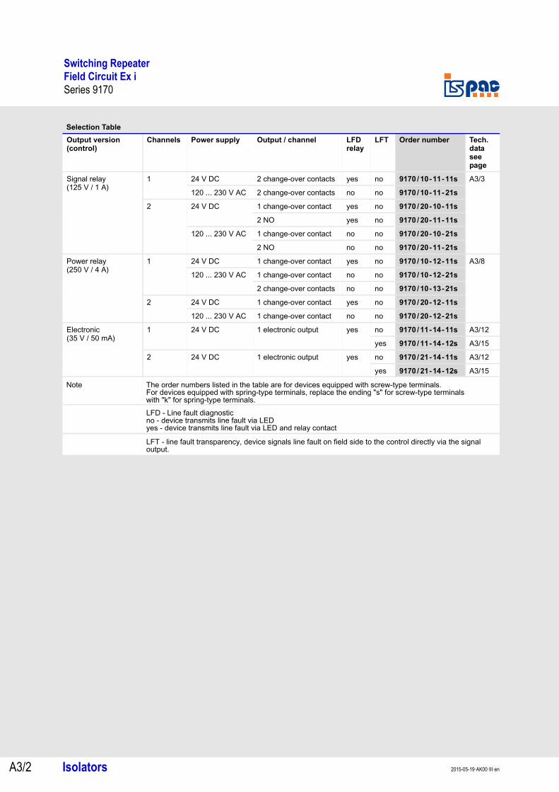
Selection Table
Output version (control)
Channels Power supply Output / channel LFDrelay
LFT Order number Tech. data see page
Signal relay(125 V / 1 A)
1 24 V DC 2 change-over contacts yes no 9170/10-11-11s A3/3
120 ... 230 V AC 2 change-over contacts no no 9170/10-11-21s
2 24 V DC 1 change-over contact yes no 9170/20-10-11s
2 NO yes no 9170/20-11-11s
120 ... 230 V AC 1 change-over contact no no 9170/20-10-21s
2 NO no no 9170/20-11-21s
Power relay(250 V / 4 A)
1 24 V DC 1 change-over contact yes no 9170/10-12-11s A3/8
120 ... 230 V AC 1 change-over contact no no 9170/10-12-21s
2 change-over contacts no no 9170/10-13-21s
2 24 V DC 1 change-over contact yes no 9170/20-12-11s
120 ... 230 V AC 1 change-over contact no no 9170/20-12-21s
Electronic(35 V / 50 mA)
1 24 V DC 1 electronic output yes no 9170/11-14-11s A3/12
yes 9170/11-14-12s A3/15
2 24 V DC 1 electronic output yes no 9170/21-14-11s A3/12
yes 9170/21-14-12s A3/15
Note The order numbers listed in the table are for devices equipped with screw-type terminals.For devices equipped with spring-type terminals, replace the ending "s" for screw-type terminals with "k" for spring-type terminals.LFD - Line fault diagnosticno - device transmits line fault via LEDyes - device transmits line fault via LED and relay contact
LFT - line fault transparency, device signals line fault on field side to the control directly via the signal output.
A3
A3
A3
A3
A3
A3
A3
A3
A3
A3
A3
A3
A3
A3
Switching Repeater with Signal relay (125 V / 1 A)Field Circuit Ex iType 9170/.0-11-.1., Type 9170/20-10-.1.
Isolators A3/32015-05-19·AK00·III·en
Type 9170/.0-11-.1., Type 9170/20-10-.1.
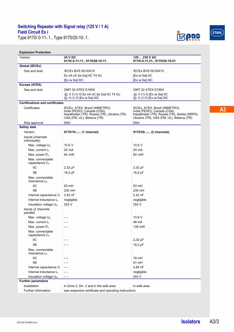
Explosion Protection
Version 24 V DC9170/.0-11-11., 9170/20-10-11.
120 ... 230 V AC9170/.0-11-21., 9170/20-10-21.
Global (IECEx)
Gas and dust IECEx BVS 09.0041X IECEx BVS 09.0041XEx nA nC [ia Ga] IIC T4 Gc [Ex ia Ga] IIC[Ex ia Da] IIIC [Ex ia Da] IIIC
Europe (ATEX)
Gas and dust DMT 02 ATEX E195X DMT 02 ATEX E195XE II 3 (1) G Ex nA nC [ia Ga] IIC T4 GcE II (1) D [Ex ia Da] IIIC
E II (1) G [Ex ia Ga] IICE II (1) D [Ex ia Da] IIIC
Certifications and certificates
Certificates IECEx, ATEX, Brazil (INMETRO), India (PESO), Canada (CSA), Kazakhstan (TR), Russia (TR), Ukraine (TR), USA (FM, UL), Belarus (TR)
IECEx, ATEX, Brazil (INMETRO), India (PESO), Canada (CSA), Kazakhstan (TR), Russia (TR), Serbia (SRPS), Ukraine (TR), USA (FM, UL), Belarus (TR)
Ship approval DNV DNVSafety data
Version 9170/10-..-.. (1 channel) 9170/20-..-.. (2 channels)
Inputs (channels individually)
Max. voltage Uo 10.6 V 10.6 V Max. current Io 24 mA 24 mA Max. power Po 64 mW 64 mW Max. connectable capacitance Co
IIC 2,32 mF 2,32 mFIIB 16,2 mF 16,2 mF
Max. connectable inductance Lo
IIC 63 mH 63 mHIIB 230 mH 230 mH
Internal capacitance Ci 2.42 nF 2.42 nFInternal inductance Li negligible negligibleInsulation voltage Um 253 V 253 V
Inputs (2 channels parallel)
Max. voltage Uo – – 10.6 VMax. current Io – – 48 mAMax. power Po – – 128 mWMax. connectable capacitance Co
IIC – – 2,32 mFIIB – – 16,2 mF
Max. connectable inductance Lo
IIC – – 16 mHIIB – – 61 mH
Internal capacitance Ci – – 4.84 nFInternal inductance Li – – negligibleInsulation voltage Um – – 253 V
Further parameters
Installation in Zone 2, Div. 2 and in the safe area in safe areaFurther information see respective certificate and operating instructions

Switching Repeater with Signal relay (125 V / 1 A)Field Circuit Ex iType 9170/.0-11-.1., Type 9170/20-10-.1.
Isolators 2015-05-19·AK00·III·enA3/4
Technical Data
Electrical data
Version 24 V DC9170/.0-11-11., 9170/20-10-11.
120 ... 230 V AC9170/.0-11-21., 9170/20-10-21.
Auxiliary powerNominal voltage UN 24 V DC 120 ... 230 V ACVoltage range 18 ... 31.2 V 96 ... 253 VResidual ripple < 3.26 VSS – –Frequency range – – 48 ... 62 Hz Nominal current at UN
1 channel 33 mA 12 mA2 channels 55 mA 18 mA
Power consumption at UN
1 channel 0.8 W 120 V AC : 1.4 VA230 V AC : 1.8 VA
2 channels 1.3 W 120 V AC : 2.2 VA230 V AC : 2.8 VA
Power dissipation1 channel 0.8 W 120 V AC: 1.0 W
230 V AC: 1.3 W2 channels 1.3 W 120 V AC: 1.6 W
230 V AC: 2.0 WPolarity reversal protection yes – –Operation indication LED green „PWR“ LED green „PWR“Undervoltage monitoring yes (no faulty module / output states) yes (no faulty module / output states)
Galvanic separationTest voltages
acc. to standard EN 60079-11 EN 60079-11Ex i input to output 1.5 kV AC 1.5 kV ACEx i input to auxiliary power 1.5 kV AC 1.5 kV ACEx i inputs interconnected 500 V AC 500 V ACEx i input to error message contact
1.5 kV AC 1.5 kV AC
acc. to standard EN 50178 EN 50178Output to auxiliary power 1.1 kV AC 1.1 kV ACOutputs interconnected 1.1 kV AC 1.1 kV ACError contact to power supply 350 V AC 350 V ACError contact to outputs 1.1 kV AC 1.1 kV AC
Ex i inputInput signal acc. to EN 60947-5-6 (NAMUR) acc. to EN 60947-5-6 (NAMUR)Current for ON / OFF
ON ) 2.1 mA ) 2.1 mAOFF ( 1.2 mA ( 1.2 mA
Hysteresis approx. 0.2 mA approx. 0.2 mA Open-circuit voltage 8.2 V 8.2 VShort-circuit current ( 8.2 mA ( 8.2 mAInternal resistance 1000 Ω 1000 Ω
OutputMinimum load 1 V / 100 mA 1 V / 100 mAMaximum load DC 125 V / 1 A 125 V / 1 AMaximum load AC 125 V / 1 A 125 V / 1 AMax. switching capacity 25 W / 50 VA 25 W / 50 VAOverload protected – – – –Voltage drop – – – –Electrical service life
Resistive load 5 x 10⁵ cycles at 24 V / 1 A 5 x 10⁵ cycles at 24 V / 1 AMechanical service life 1 x 10⁸ cycles 1 x 10⁸ cyclesRecommended back-up fuses ( F 1 A AC / DC ( F 1 A AC / DCMax. switching frequency 15 Hz 15 Hz Switching delay ON / OFF 5 ms 5 msSwitching delay OFF / ON 5 ms 5 msSettings (switch INV) Inversion of operating mode Inversion of operating modeIndication LED yellow „OUT“ per channel LED yellow „OUT“ per channel

A3
A3
A3
A3
A3
A3
A3
A3
A3
A3
A3
A3
A3
A3
Switching Repeater with Signal relay (125 V / 1 A)Field Circuit Ex iType 9170/.0-11-.1., Type 9170/20-10-.1.
Isolators A3/52015-05-19·AK00·III·en
Electrical dataError detection Ex i input
Open circuit Iin < 0.05 ... 0.35 mAaccording to EN 60947-5-6
Short circuit Rin < 100 ... 360 Ωaccording to EN 60947-5-6
Behaviour of the output OFFSettings (switch LF) activated / deactivatedError detection LED red "LF" each channelMessage of line fault and auxiliary power failure
- contact (30 V / 100 mA), closed to ground in case of fault *)- pac-Bus, floating contact (30 V / 100 mA) *)*) not at 9170/.0-1.-21.
Electromagnetic compatibility Tested under the following standards and regulations: EN 61326-1 (can be used in industrial environment)NAMUR NE 21
Ambient conditions
Ambient temperatureSingle device -20 ... +70 °CGroup assembly -20 ... +60 °C
The installation conditions affect the ambient temperature.Observe the "Cabinet installation guide".
Storage temperature -40 ... +80 °C Relative humidity (no condensation) ( 95 %
Technical Data
Switching Repeater with Signal relay (125 V / 1 A)Field Circuit Ex iType 9170/.0-11-.1., Type 9170/20-10-.1.
Isolators 2015-05-19·AK00·III·enA3/6
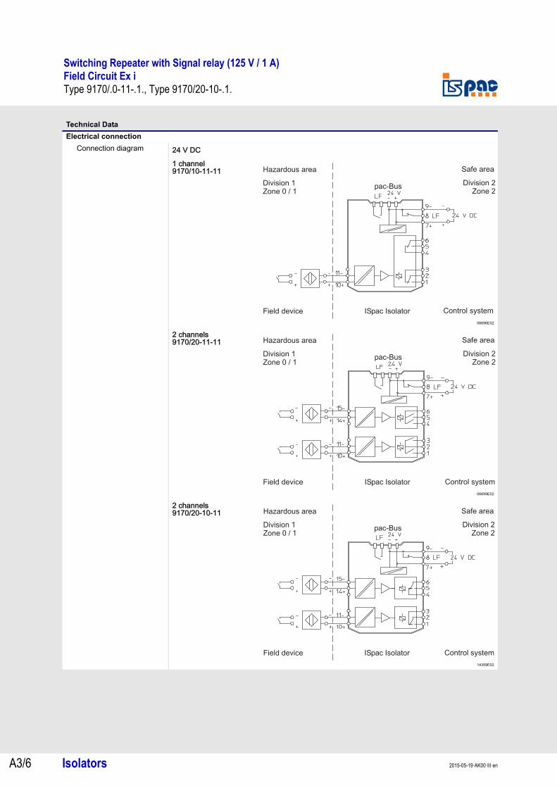
Technical Data
Electrical connection
Connection diagram 24 V DC
1 channel9170/10-11-11
06696E02
2 channels9170/20-11-11
06699E02
2 channels9170/20-10-11
14359E02
pac-Bus
Hazardous area Safe area
Field device ISpac Isolator Control system
Division 1Zone 0 / 1
Division 2Zone 2
pac-Bus
Hazardous area Safe area
Field device ISpac Isolator Control system
Division 1Zone 0 / 1
Division 2Zone 2
pac Bus-
Hazardous area Safe area
Field device ISpac Isolator Control system
Division 1
Zone 0 / 1
Division 2
Zone 2
A3
A3
A3
A3
A3
A3
A3
A3
A3
A3
A3
A3
A3
A3
Switching Repeater with Signal relay (125 V / 1 A)Field Circuit Ex iType 9170/.0-11-.1., Type 9170/20-10-.1.
Isolators A3/72015-05-19·AK00·III·en
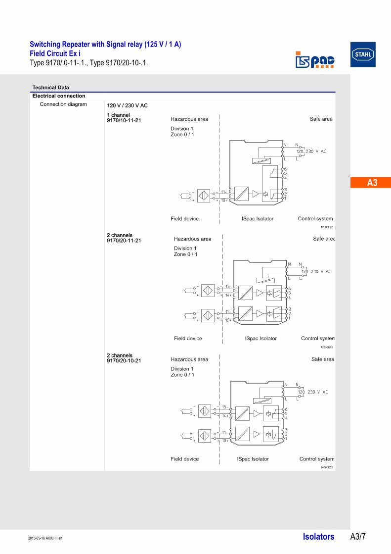
Technical Data
Electrical connection
Connection diagram 120 V / 230 V AC
1 channel9170/10-11-21
12835E02
2 channels9170/20-11-21
12836E02
2 channels9170/20-10-21
14360E02
Hazardous area Safe area
Field device ISpac Isolator Control system
Division 1Zone 0 / 1
Hazardous area Safe area
Field device ISpac Isolator Control system
Division 1Zone 0 / 1
Switching Repeater with Power Relay (250 V / 4 A)Field Circuit Ex iType 9170/.0-12-.1., Type 9170/.0-13-21.
Isolators 2015-05-19·AK00·III·enA3/8
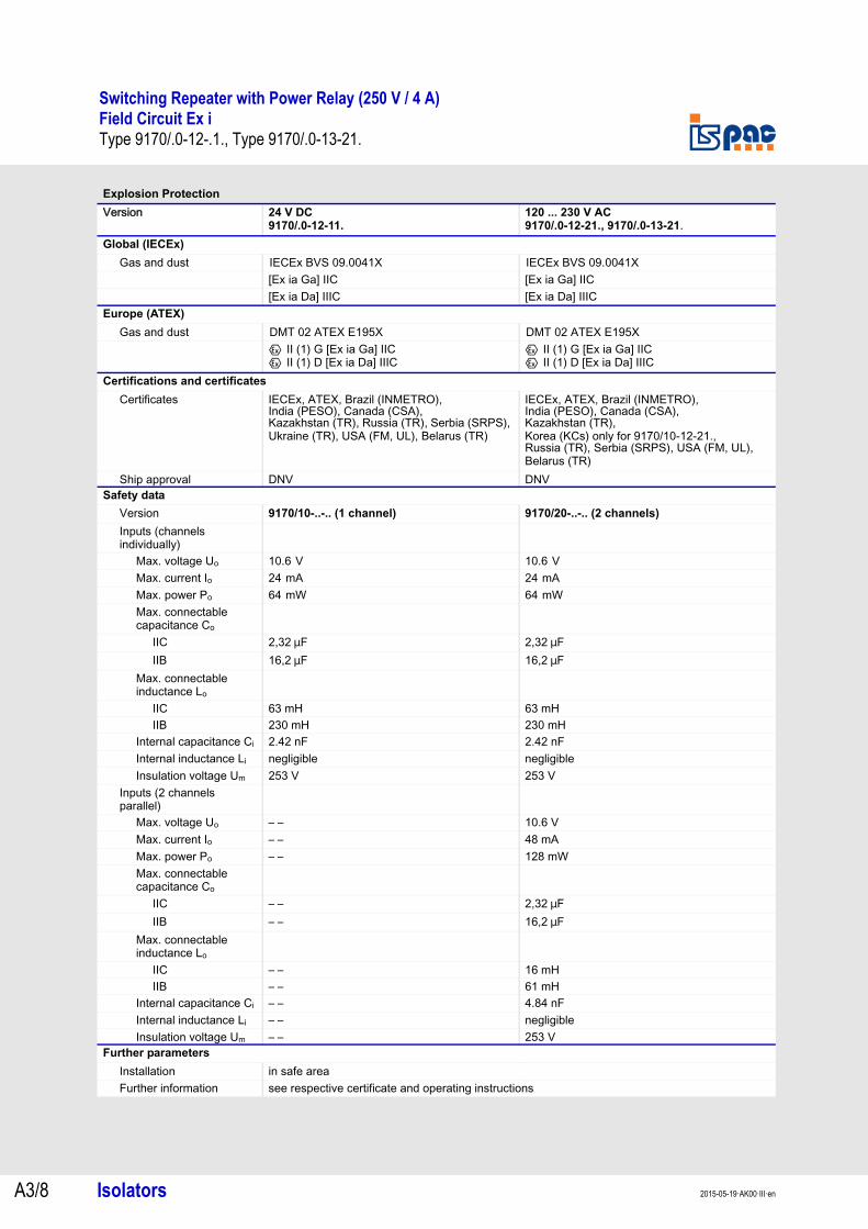
Type 9170/.0-12-.1., Type 9170/.0-13-21.
Explosion Protection
Version 24 V DC9170/.0-12-11.
120 ... 230 V AC9170/.0-12-21., 9170/.0-13-21.
Global (IECEx)
Gas and dust IECEx BVS 09.0041X IECEx BVS 09.0041X[Ex ia Ga] IIC [Ex ia Ga] IIC[Ex ia Da] IIIC [Ex ia Da] IIIC
Europe (ATEX)
Gas and dust DMT 02 ATEX E195X DMT 02 ATEX E195XE II (1) G [Ex ia Ga] IICE II (1) D [Ex ia Da] IIIC
E II (1) G [Ex ia Ga] IICE II (1) D [Ex ia Da] IIIC
Certifications and certificates
Certificates IECEx, ATEX, Brazil (INMETRO), India (PESO), Canada (CSA), Kazakhstan (TR), Russia (TR), Serbia (SRPS), Ukraine (TR), USA (FM, UL), Belarus (TR)
IECEx, ATEX, Brazil (INMETRO),India (PESO), Canada (CSA), Kazakhstan (TR), Korea (KCs) only for 9170/10-12-21., Russia (TR), Serbia (SRPS), USA (FM, UL), Belarus (TR)
Ship approval DNV DNVSafety data
Version 9170/10-..-.. (1 channel) 9170/20-..-.. (2 channels)
Inputs (channels individually)
Max. voltage Uo 10.6 V 10.6 V Max. current Io 24 mA 24 mA Max. power Po 64 mW 64 mW Max. connectable capacitance Co
IIC 2,32 mF 2,32 mFIIB 16,2 mF 16,2 mF
Max. connectable inductance Lo
IIC 63 mH 63 mHIIB 230 mH 230 mH
Internal capacitance Ci 2.42 nF 2.42 nFInternal inductance Li negligible negligibleInsulation voltage Um 253 V 253 V
Inputs (2 channels parallel)
Max. voltage Uo – – 10.6 VMax. current Io – – 48 mAMax. power Po – – 128 mWMax. connectable capacitance Co
IIC – – 2,32 mFIIB – – 16,2 mF
Max. connectable inductance Lo
IIC – – 16 mHIIB – – 61 mH
Internal capacitance Ci – – 4.84 nFInternal inductance Li – – negligibleInsulation voltage Um – – 253 V
Further parameters
Installation in safe areaFurther information see respective certificate and operating instructions

A3
A3
A3
A3
A3
A3
A3
A3
A3
A3
A3
A3
A3
A3
Switching Repeater with Power Relay (250 V / 4 A)Field Circuit Ex iType 9170/.0-12-.1., Type 9170/.0-13-21.
Isolators A3/92015-05-19·AK00·III·en
Technical Data
Electrical data
Version 24 V DC9170/.0-12-11.
120 ... 230 V AC9170/.0-12-21., 9170/.0-13-21.
Auxiliary powerNominal voltage UN 24 V DC 120 ... 230 V ACVoltage range 18 ... 31.2 V 96 ... 253 VResidual ripple < 3.26 VSS – –Frequency range 48 ... 62 Hz Nominal current at UN
1 channel 33 mA 12 mA2 channels 55 mA 18 mA
Power consumption at UN1 channel 0.8 W 120 V AC : 1.4 VA
230 V AC : 1.8 VA2 channels 1.3 W 120 V AC : 2.2 VA
230 V AC : 2.8 VAPower dissipation
1 channel 0.8 W 120 V AC: 1.0 W230 V AC: 1.3 W
2 channels 1.3 W 120 V AC: 1.6 W230 V AC: 2.0 W
Polarity reversal protection yes – –Operation indication LED green „PWR“ LED green „PWR“Undervoltage monitoring yes (no faulty module / output states) yes (no faulty module / output states)
Galvanic separationTest voltages
acc. to standard EN 60079-11 EN 60079-11Ex i input to output 1.5 kV AC 1.5 kV ACEx i input to auxiliary power 1.5 kV AC 1.5 kV ACEx i inputs interconnected 500 V AC 500 V ACEx i input to error message contact
1.5 kV AC 1.5 kV AC
acc. to standard EN 50178 EN 50178Output to auxiliary power 1.1 kV AC 1.1 kV ACOutputs interconnected 1.1 kV AC 1.1 kV ACError contact to power supply 350 V AC 350 V ACError contact to outputs 1.1 kV AC 1.1 kV AC
Ex i inputInput signal acc. to EN 60947-5-6 (NAMUR) acc. to EN 60947-5-6 (NAMUR)Current for ON / OFF
ON ) 2.1 mA ) 2.1 mAOFF ( 1.2 mA ( 1.2 mA
Hysteresis approx. 0.2 mA approx. 0.2 mA Open-circuit voltage 8.2 V 8.2 VShort-circuit current ( 8.2 mA ( 8.2 mAInternal resistance 1000 Ω 1000 Ω
OutputMinimum load 12 V / 100 mA 12 V / 100 mAMaximum load DC 250 V / 2 A 250 V / 2 AMaximum load AC 250 V / 4 A 250 V / 4 AMax. switching capacity 50 W / 1000 VA 50 W / 1000 VAOverload protected – – – –Voltage drop – – – –Electrical service life
Resistive load 1 x 10⁵ cycles at 250 V / 4 A 1 x 10⁵ cycles at 250 V / 4 AMechanical service life 15 x 106 cycles 15 x 106 cyclesRecommended back-up fuses ( F 4 A AC / 2 A DC ( F 4 A AC / 2 A DCMax. switching frequency 6 Hz 6 Hz Switching delay ON / OFF 10 ms 10 msSwitching delay OFF / ON 10 ms 10 msSettings (switch INV) Inversion of operating mode Inversion of operating modeIndication LED yellow „OUT“ per channel LED yellow „OUT“ per channel
Switching Repeater with Power Relay (250 V / 4 A)Field Circuit Ex iType 9170/.0-12-.1., Type 9170/.0-13-21.
Isolators 2015-05-19·AK00·III·enA3/10
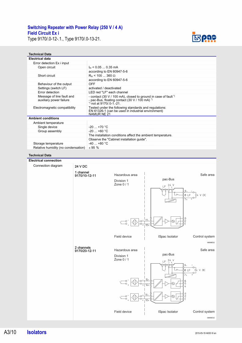
Electrical dataError detection Ex i input
Open circuit Iin < 0.05 ... 0.35 mAaccording to EN 60947-5-6
Short circuit Rin < 100 ... 360 Ωaccording to EN 60947-5-6
Behaviour of the output OFFSettings (switch LF) activated / deactivatedError detection LED red "LF" each channelMessage of line fault and auxiliary power failure
- contact (30 V / 100 mA), closed to ground in case of fault *)- pac-Bus, floating contact (30 V / 100 mA) *)*) not at 9170/.0-1.-21.
Electromagnetic compatibility Tested under the following standards and regulations: EN 61326-1 (can be used in industrial environment)NAMUR NE 21
Ambient conditions
Ambient temperatureSingle device -20 ... +70 °CGroup assembly -20 ... +60 °C
The installation conditions affect the ambient temperature.Observe the "Cabinet installation guide".
Storage temperature -40 ... +80 °C Relative humidity (no condensation) ( 95 %
Technical Data
Electrical connection
Connection diagram
Technical Data
24 V DC
1 channel9170/10-12-11
06698E02
2 channels9170/20-12-11
06695E02
Hazardous area Safe area
Field device ISpac Isolator Control system
Division 1Zone 0 / 1
pac-Bus
Hazardous area Safe area
Field device ISpac Isolator Control system
Division 1Zone 0 / 1
pac-Bus
A3
A3
A3
A3
A3
A3
A3
A3
A3
A3
A3
A3
A3
A3
Switching Repeater with Power Relay (250 V / 4 A)Field Circuit Ex iType 9170/.0-12-.1., Type 9170/.0-13-21.
Isolators A3/112015-05-19·AK00·III·en
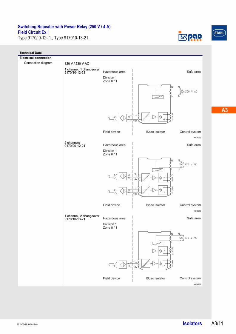
Technical Data
Electrical connection
Connection diagram 120 V / 230 V AC
1 channel, 1 changeover9170/10-12-21
06871E02
2 channels9170/20-12-21
07219E02
1 channel, 2 changeover9170/10-13-21
06874E02
Hazardous area Safe area
Field device ISpac Isolator Control system
Division 1Zone 0 / 1
Hazardous area Safe area
Field device ISpac Isolator Control system
Division 1Zone 0 / 1
Hazardous area Safe area
Field device ISpac Isolator Control system
Division 1Zone 0 / 1
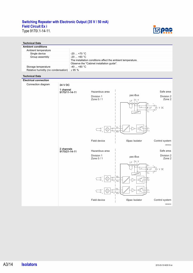
Switching Repeater with Electronic Output (35 V / 50 mA)Field Circuit Ex iType 9170/.1-14-11.
Isolators 2015-05-19·AK00·III·enA3/12
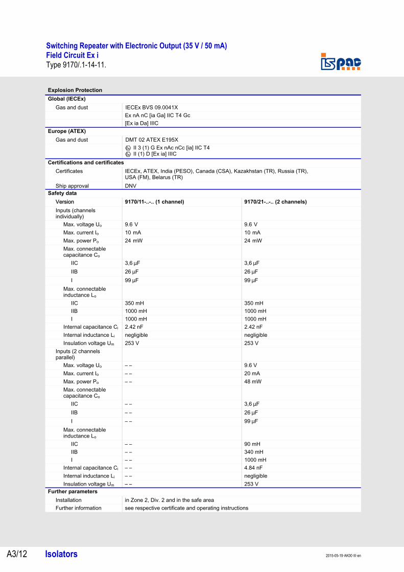
Type 9170/.1-14-11.
Explosion Protection
Global (IECEx)
Gas and dust IECEx BVS 09.0041XEx nA nC [ia Ga] IIC T4 Gc[Ex ia Da] IIIC
Europe (ATEX)
Gas and dust DMT 02 ATEX E195XE II 3 (1) G Ex nAc nCc [ia] IIC T4E II (1) D [Ex ia] IIIC
Certifications and certificates
Certificates IECEx, ATEX, India (PESO), Canada (CSA), Kazakhstan (TR), Russia (TR), USA (FM), Belarus (TR)
Ship approval DNVSafety data
Version 9170/11-..-.. (1 channel) 9170/21-..-.. (2 channels)
Inputs (channels individually)
Max. voltage Uo 9.6 V 9.6 V Max. current Io 10 mA 10 mA Max. power Po 24 mW 24 mW Max. connectable capacitance Co
IIC 3,6 mF 3,6 mFIIB 26 mF 26 mFI 99 mF 99 mF
Max. connectable inductance Lo
IIC 350 mH 350 mHIIB 1000 mH 1000 mHI 1000 mH 1000 mH
Internal capacitance Ci 2.42 nF 2.42 nFInternal inductance Li negligible negligibleInsulation voltage Um 253 V 253 V
Inputs (2 channels parallel)
Max. voltage Uo – – 9.6 VMax. current Io – – 20 mAMax. power Po – – 48 mWMax. connectable capacitance Co
IIC – – 3,6 mFIIB – – 26 mFI – – 99 mF
Max. connectable inductance Lo
IIC – – 90 mHIIB – – 340 mHI – – 1000 mH
Internal capacitance Ci – – 4.84 nFInternal inductance Li – – negligibleInsulation voltage Um – – 253 V
Further parameters
Installation in Zone 2, Div. 2 and in the safe areaFurther information see respective certificate and operating instructions

A3
A3
A3
A3
A3
A3
A3
A3
A3
A3
A3
A3
A3
A3
Switching Repeater with Electronic Output (35 V / 50 mA)Field Circuit Ex iType 9170/.1-14-11.
Isolators A3/132015-05-19·AK00·III·en
Technical Data
Electrical data
Auxiliary powerNominal voltage UN 24 V DCVoltage range 18 ... 31.2 VResidual ripple < 3.26 VSSNominal current at UN
1 channel 26 mA2 channels 36 mA
Power consumption at UN1 channel 0.6 W2 channels 0.9 W
Power dissipation1 channel 0.6 W2 channels 0.9 W
Polarity reversal protection yesOperation indication LED green „PWR“Undervoltage monitoring yes (no faulty module / output states)
Galvanic separationTest voltages
acc. to standard EN 60079-11Ex i input to output 1.5 kV ACEx i input to auxiliary power 1.5 kV ACEx i inputs interconnected 500 V ACEx i input to error message contact
1.5 kV AC
acc. to standard EN 50178Output to auxiliary power 1.1 kV ACOutputs interconnected 1.1 kV ACError contact to power supply 350 V ACError contact to outputs 1.1 kV AC
Ex i inputInput signal acc. to EN 60947-5-6 (NAMUR)Current for ON / OFF
ON ) 2.1 mAOFF ( 1.2 mA
Hysteresis approx. 0.2 mA Open-circuit voltage 8.2 VShort-circuit current ( 8.2 mAInternal resistance 1000 Ω
OutputMaximum load DC 35 V / 50 mA DCMaximum load AC – –Max. switching capacity 1.75 WOverload protected yesVoltage drop < 2 VElectrical service life
Resistive load > 109 cycles at 35 V / 50 mAMax. switching frequency 10 kHz Switching delay ON / OFF 15 msSwitching delay OFF / ON 30 msSettings (switch INV) Inversion of operating modeIndication LED yellow „OUT“ per channel
Error detection Ex i inputOpen circuit Iin < 0.05 ... 0.35 mA
according to EN 60947-5-6Short circuit Rin < 100 ... 360 Ω
according to EN 60947-5-6Behaviour of the output OFFSettings (switch LF) activated / deactivatedError detection LED red "LF" each channelMessage of line fault and auxiliary power failure
- contact (30 V / 100 mA), closed to ground in case of fault- pac-Bus, floating contact (30 V / 100 mA)
Electromagnetic compatibility Tested under the following standards and regulations: EN 61326-1 (can be used in industrial environment)NAMUR NE 21
Switching Repeater with Electronic Output (35 V / 50 mA)Field Circuit Ex iType 9170/.1-14-11.
Isolators 2015-05-19·AK00·III·enA3/14
Ambient conditions
Ambient temperatureSingle device -20 ... +70 °CGroup assembly -20 ... +60 °C
The installation conditions affect the ambient temperature.Observe the "Cabinet installation guide".
Storage temperature -40 ... +80 °C Relative humidity (no condensation) ( 95 %
Technical Data
Electrical connection
Connection diagram
Technical Data
24 V DC
1 channel9170/11-14-11
06693E02
2 channels9170/21-14-11
06694E02
Hazardous area Safe area
Field device ISpac Isolator Control system
Division 1Zone 0 / 1
Division 2Zone 2
pac-Bus
Hazardous area Safe area
Field device ISpac Isolator Control system
Division 1Zone 0 / 1
Division 2Zone 2
pac-Bus
A3
A3
A3
A3
A3
A3
A3
A3
A3
A3
A3
A3
A3
A3
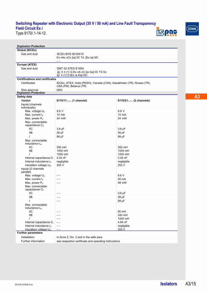
Switching Repeater with Electronic Output (35 V / 50 mA) and Line Fault TransparencyField Circuit Ex iType 9170/.1-14-12.
Isolators A3/152015-05-19·AK00·III·en
Type 9170/.1-14-12.
Explosion Protection
Global (IECEx)
Gas and dust IECEx BVS 09.0041XEx nAc nCc [ia] IIC T4, [Ex ia] IIIC– –
Europe (ATEX)
Gas and dust DMT 02 ATEX E195XE II 3 (1) G Ex nA nC [ia Ga] IIC T4 GcE II (1) D [Ex ia Da] IIIC
Certifications and certificates
Certificates IECEx, ATEX, India (PESO), Canada (CSA), Kazakhstan (TR), Russia (TR), USA (FM), Belarus (TR)
Ship approval DNVExplosion Protection
Safety data
Version 9170/11-..-.. (1 channel) 9170/21-..-.. (2 channels)
Inputs (channels individually)
Max. voltage Uo 9.6 V 9.6 V Max. current Io 10 mA 10 mA Max. power Po 24 mW 24 mW Max. connectable capacitance Co
IIC 3,6 mF 3,6 mFIIB 26 mF 26 mFI 99 mF 99 mF
Max. connectable inductance Lo
IIC 350 mH 350 mHIIB 1000 mH 1000 mHI 1000 mH 1000 mH
Internal capacitance Ci 2.42 nF 2.42 nFInternal inductance Li negligible negligibleInsulation voltage Um 253 V 253 V
Inputs (2 channels parallel)
Max. voltage Uo – – 9.6 VMax. current Io – – 20 mAMax. power Po – – 48 mWMax. connectable capacitance Co
IIC – – 3,6 mFIIB – – 26 mFI – – 99 mF
Max. connectable inductance Lo
IIC – – 90 mHIIB – – 340 mHI – – 1000 mH
Internal capacitance Ci – – 4.84 nFInternal inductance Li – – negligibleInsulation voltage Um – – 253 V
Further parameters
Installation in Zone 2, Div. 2 and in the safe areaFurther information see respective certificate and operating instructions
Switching Repeater with Electronic Output (35 V / 50 mA) and Line Fault TransparencyField Circuit Ex iType 9170/.1-14-12.
Isolators 2015-05-19·AK00·III·enA3/16
Technical Data
Electrical data
Auxiliary powerNominal voltage UN 24 V DCVoltage range 18 ... 31.2 VResidual ripple < 3.26 VSSNominal current at UN
1 channel 26 mA2 channels 36 mA
Power consumption at UN
1 channel 0.6 W2 channels 1.9 W
Power dissipation1 channel 0.6 W2 channels 1.9 W
Polarity reversal protection yesOperation indication LED green „PWR“Undervoltage monitoring yes (no faulty module / output states)
Galvanic separationTest voltages
acc. to standard EN 60079-11Ex i input to output 1.5 kV ACEx i input to auxiliary power 1.5 kV ACEx i inputs interconnected 500 V ACEx i input to error message contact
1.5 kV AC
acc. to standard EN 50178Output to auxiliary power 1.1 kV ACOutputs interconnected 1.1 kV ACError contact to power supply 350 V ACError contact to outputs 1.1 kV AC
Ex i inputInput signal acc. to EN 60947-5-6 (NAMUR)Current for ON / OFF
ON ) 2.1 mAOFF ( 1.2 mA
Hysteresis approx. 0.2 mA Open-circuit voltage 8.2 VShort-circuit current ( 8.2 mAInternal resistance 1000 Ω
OutputMaximum load DC 35 V / 50 mA DCMaximum load AC – –Max. switching capacity 1.75 WOverload protected yesElectrical service life
Resistive load > 109 cycles at 35 V / 50 mAMax. switching frequency 10 kHz Switching delay ON / OFF 15 msSwitching delay OFF / ON 30 msElectronic output closed R = 2.4 k ΩElectronic output opened R > 13 k ΩIn case of error (signalisation contact open)
R > 100 k Ω
Settings (switch INV) Inversion of operating modeIndication LED yellow „OUT“ per channel
A3
A3
A3
A3
A3
A3
A3
A3
A3
A3
A3
A3
A3
A3
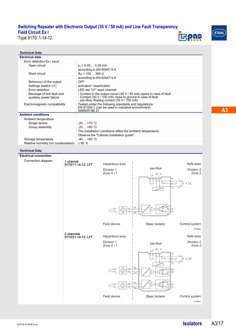
Switching Repeater with Electronic Output (35 V / 50 mA) and Line Fault TransparencyField Circuit Ex iType 9170/.1-14-12.
Isolators A3/172015-05-19·AK00·III·en
Electrical dataError detection Ex i input
Open circuit Iin < 0.05 ... 0.35 mAaccording to EN 60947-5-6
Short circuit Rin < 100 ... 360 Ωaccording to EN 60947-5-6
Behaviour of the output OFFSettings (switch LF) activated / deactivatedError detection LED red "LF" each channelMessage of line fault and auxiliary power failure
- Contact in the output circuit (35 V / 50 mA) opens in case of fault- Contact (30 V / 100 mA) close to ground in case of fault- pac-Bus, floating contact (30 V / 100 mA)
Electromagnetic compatibility Tested under the following standards and regulations: EN 61326-1 (can be used in industrial environment)NAMUR NE 21
Ambient conditions
Ambient temperatureSingle device -20 ... +70 °CGroup assembly -20 ... +60 °C
The installation conditions affect the ambient temperature.Observe the "Cabinet installation guide".
Storage temperature -40 ... +80 °C Relative humidity (no condensation) ( 95 %
Technical Data
Electrical connection
Connection diagram
Technical Data
1 channel9170/11-14-12. LFT
07789E02
2 channels9170/21-14-12. LFT
07790E02
Hazardous area Safe area
Field device ISpac Isolator Control system
Division 1Zone 0 / 1
Division 2Zone 2
pac-Bus
Hazardous area Safe area
Field device ISpac Isolator Control system
Division 1Zone 0 / 1
Division 2Zone 2
pac-Bus
Switching RepeaterField Circuit Ex iSeries 9170
Isolators 2015-05-19·AK00·III·enA3/18
Series 9170
Technical Data
Mechanical data
Connection
Weight approx. 160 g Mounting type on top hat rail (NS35/15, NS35/7.5) or in pac-CarrierMounting orientation horizontal or verticalEnclosure IP30Terminals IP20Enclosure material PA 6.6Fire resistance (UL-94) V0
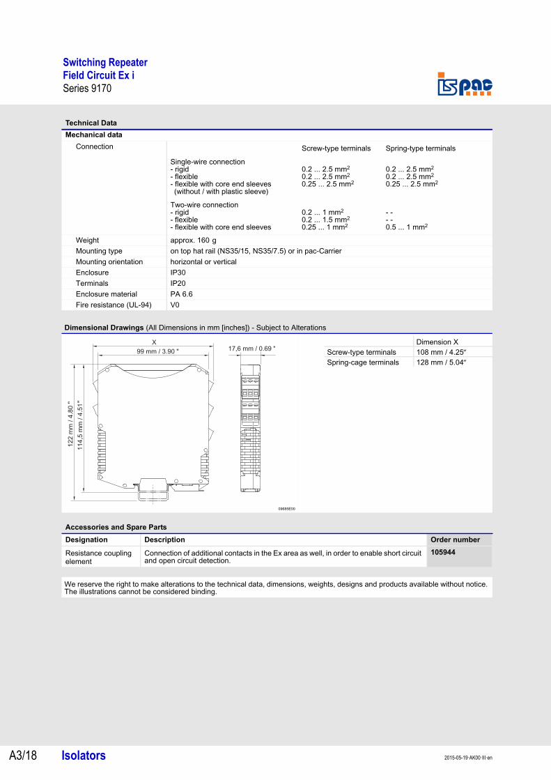
Dimensional Drawings (All Dimensions in mm [inches]) - Subject to Alterations
09685E00
Accessories and Spare Parts
Designation Description Order number
Resistance coupling element
Connection of additional contacts in the Ex area as well, in order to enable short circuit and open circuit detection.
105944
We reserve the right to make alterations to the technical data, dimensions, weights, designs and products available without notice. The illustrations cannot be considered binding.
Screw-type terminals Spring-type terminals
Single-wire connection- rigid- flexible- flexible with core end sleeves (without / with plastic sleeve)
0.2 ... 2.5 mm2
0.2 ... 2.5 mm2
0.25 ... 2.5 mm2
0.2 ... 2.5 mm2
0.2 ... 2.5 mm2
0.25 ... 2.5 mm2
Two-wire connection- rigid- flexible- flexible with core end sleeves
0.2 ... 1 mm2
0.2 ... 1.5 mm2
0.25 ... 1 mm2
- -- -0.5 ... 1 mm2
X
122 m
m / 4
.80
"
114,5
mm
/ 4
.51
"
99 mm / 3.90 " 17,6 mm / 0.69 "Dimension X
Screw-type terminals 108 mm / 4.25Spring-cage terminals 128 mm / 5.04
Recommended