45
Journal of Engineering Sciences
Assiut University
Faculty of Engineering
Invited paper 2
Vol. 43
No. 1
January 2015
PP. 45 – 56
* Corresponding author.
Email address: [email protected]
A NOVEL MULTISTAGE FUZZY CONTROLLER FOR FACTS
STABILIZATION SCHEME FOR SMIB AC SYSTEM
Abdel-Fattah Attia 1 and Adel M. Sharaf
2
1 Kafrelsheikh University, Faculty of Engineering, Dept., of Electrical Eng., Kafrelsheikh, Egypt
2 Life Senior Member, IEEE, Sharaf Energy Systems, Inc., Fredericton, NB-Canada
ABSTRACT
The paper presents a novel Hybrid-FACTS Based Stabilization Scheme controlled by a hierarchical
two-stage fuzzy logic (HFLC)-multi loop dynamic error driven controller. The proposed scheme
includes separate Fuzzy control stages for the PD and PID parts to ensure robust and effective dynamic
speed control and efficient energy utilization. The PD fuzzy stage used the global error and change of
error as the fuzzy input variables. The second stage is the PID-FLC regulation which utilizes the
output of the PD-FLC stage and the integral of the global error as input fuzzy variables. The
simulation results validate the proposed control scheme effectiveness and robustness with efficient
energy utilization, improved power quality and power factor at the Common AC Bus and load bus. A
Digital simulation model of the proposed system is developed in Matlab/Simulink/Simpower Software
Environment using operational dynamic blocks available in Simulink library.
Keywords: Multi-Stage Fuzzy logic dynamic controller; FACTS; Hybrid Switched Capacitive
compensator-HSCC; efficient energy utilization, voltage stabilization.
1. Introduction
The power quality, Smart Grid Efficient Utilizations and voltage stabilization are now key
operational issues. The use of static power converters in electricity has the potential for
increasing the capacity of transmission line and improving the supply quality of the electric
energy. Flexible AC transmission system (FACTS) devices are used in transmission control
whereas custom power devices are used for distribution control. Advantage of modern control
systems for switching for modulated filter schemes [1]. A hybrid switched power filter
Topology with PWM-switched Strategies is used and validated for energy utilization
enhancement, power quality, loss reduction and power factor correction. The hybrid Filter-
compensation scheme is suitable in hybrid Renewable Energy-smart grid networks [2-5]. The
conventional proportional-integral-derivative (PID) type controller is the best controller used in
practice. Because of its simplicity for design and its gain parameters can be tuned manually,
using Ziegler-Nichols, analytical methods, Tabu search [6], particle swarm optimization [7],

46
JES, Assiut University, Faculty of Engineering, Vol. 43, No. 1, January 2015, pp. 45 – 56
Genetic Algorithm [8], pole placement method etc. A hierarchical multi-stage fuzzy logic
controller has parallel and series levels where the output of one level becomes the input to the
other [13-15]. Typically, pairs of inputs are fuzzified and applied to the rules of the preliminary
levels. The outputs of these levels are applied to the rules of subsequent levels of the fuzzy
logic system until the result of the final level gives the output of the complete fuzzy logic
controller [9].This study introduces a novel Hybrid Series-Parallel Switched Capacitor
Compensation (HSCC) is assessed and validated as a tool in improving power quality and
efficient energy delivery for a SMIB-AC system [4]. Two proposed dynamic Control schemes
are designed using multi-loop dynamic error driven time-descaled and coordinated regulation
scheme. The first is PID controller with fixed gains for the regulator. The second is the
hierarchical Fuzzy Logic Controller that used the global error and change of error as input
variables. A complete simulation model of the proposed system is developed in
Matlab/Simulink/Simpower Software Environment using operational dynamic blocks available
in Simulink library. This paper is organized as follows. Following introduction, The Hybrid
Switched Capacitor Compensation (HSCC) scheme is given. Then the proposed Multi-Tier
Fuzzy logic controller is explained. The system simulation with proposed control technique
under different operating conditions are preceded the discussion of the results and conclusions.
2. The hybrid series-parallel switched capacitor compensation (HSCC) scheme
The configuration of the proposed HSCC scheme is shown in Fig. 1.
Fig. 1. Hybrid Series-Parallel Switched Capacitor Compensation (HSCC)
scheme Located at Feeder Mid-Point.
This device is a switched/modulated hybrid power filter comprising a shunt capacitor
bank connected to AC side of a three-arm uncontrolled rectifier in addition to a second
47
Abdel-Fattah Attia 1 and Adel M. Sharaf, A novel multistage fuzzy controller for facts ………………
series switched capacitor bank forming blocking filter. The operational mode of FACTS is
defined as follows based on the two controlled signals: Switches S2, S3, S4 and S5 are
controlled by PWM pulses through P2 and P3. Whereas S1 is controlled by pulses comes
from PWM through P1. The two triggering pulses are complementary with. It means
switching of the Parallel Capacitor bank dictates the on/off modes of the series capacitor
bank, hence operating as a hybrid switched filter-compensation scheme.
3. Dynamic error driven control
The dynamic error driven controller [10-12] is used for the the hybrid FACTS based Device.
Three regulation loops are utilized with the first regulator A including three time-descaled
weighted loops. The first loop stabilizes the voltage to a specified reference valueand theother
two loops are used to dynamically stabilizeCurrent and power sudden changes and excursions.
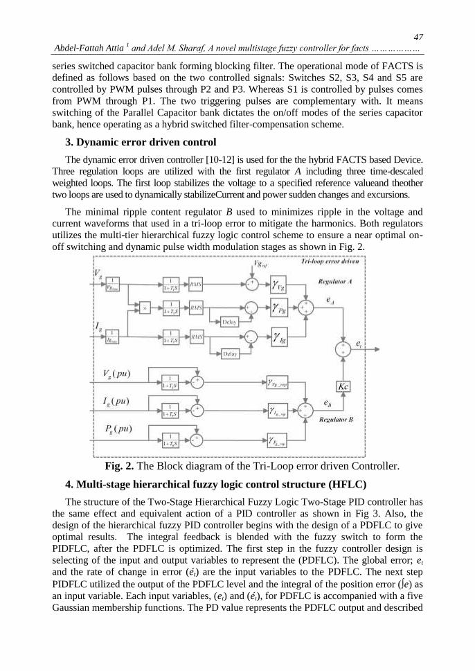
The minimal ripple content regulator B used to minimizes ripple in the voltage and
current waveforms that used in a tri-loop error to mitigate the harmonics. Both regulators
utilizes the multi-tier hierarchical fuzzy logic control scheme to ensure a near optimal on-
off switching and dynamic pulse width modulation stages as shown in Fig. 2.
Fig. 2. The Block diagram of the Tri-Loop error driven Controller.
4. Multi-stage hierarchical fuzzy logic control structure (HFLC)
The structure of the Two-Stage Hierarchical Fuzzy Logic Two-Stage PID controller has
the same effect and equivalent action of a PID controller as shown in Fig 3. Also, the
design of the hierarchical fuzzy PID controller begins with the design of a PDFLC to give
optimal results. The integral feedback is blended with the fuzzy switch to form the
PIDFLC, after the PDFLC is optimized. The first step in the fuzzy controller design is
selecting of the input and output variables to represent the (PDFLC). The global error; et
and the rate of change in error (ét) are the input variables to the PDFLC. The next step
PIDFLC utilized the output of the PDFLC level and the integral of the position error (e) as
an input variable. Each input variables, (et) and (ét), for PDFLC is accompanied with a five
Gaussian membership functions. The PD value represents the PDFLC output and described

48
JES, Assiut University, Faculty of Engineering, Vol. 43, No. 1, January 2015, pp. 45 – 56
by a five membership functions. A full rule base, 25 rules, is also defined for PDFLC. The
rules have the general form:
If is and is then is . t te NS e Z PD value NS
Fig. 3. Two-Level Hierarchal Fuzzy Logic Controller for (HSCC FACTS)
energy utilization system.
Where the membership functions (mfi) is defined as follows: mfjNL, NS, Z, PS and
PL However, the output space has 25 different fuzzy sets. The PIDFLC represents the
decision maker of the hierarchical fuzzy controller and its structure has two input variables
PD value which is the output of PDFLC and the error integrator et. The PD input variable
accompanied with five fuzzy set, while the second input variable, error integral, is
evaluated through three fuzzy set. Therefore, the PIDFLC used a full rule base equal 15
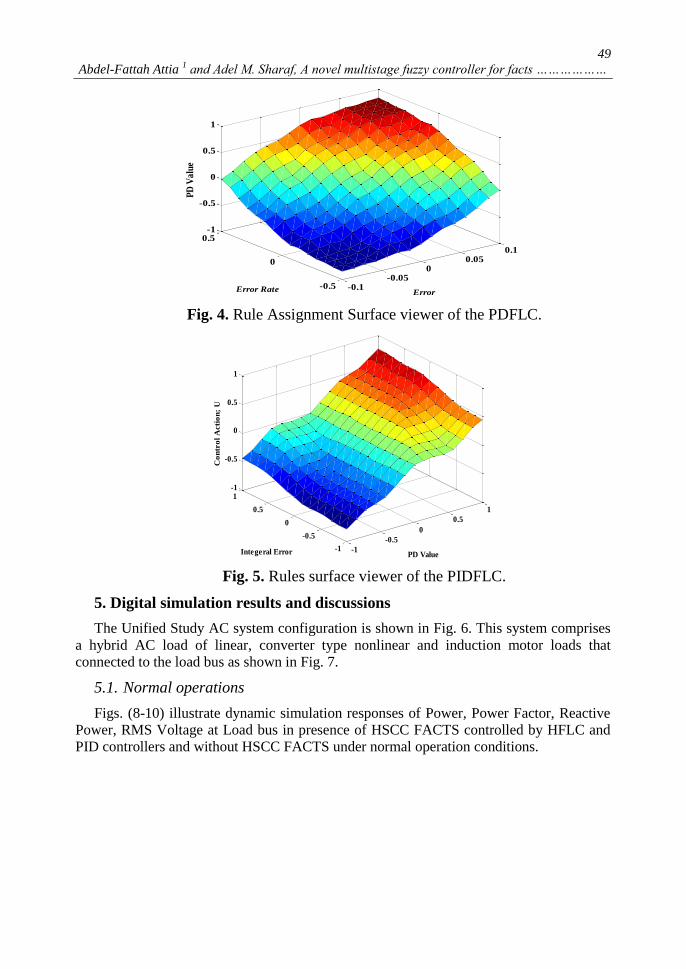
rules. In addition, Fig. 4 and Fig. 5 show the surface rule viewers for the two controllers;
PDFLC and PIDFLC respectively. So, the full rules base of the HFLC is 40 rules instead
of 125 rules for the classical FLC method used three input variables.
The output signal (U) of the Multi-Tier Hierarchical Fuzzy Logic Control Structure
(HFLC) is used to control the switching sequence of the PWM-modulation The on-off
switching pattern is dynamically modified based on control signals, hence controlling the
two operating modes of the FACTS device as either a Filter or reactive power
compensator. A novel fast acting Weighted-Modified PID controller (WMPID) is used
[5]. The simulation results compare between the proposed (HFLC) with WMPID
controllers for FACTS.
49
Abdel-Fattah Attia 1 and Adel M. Sharaf, A novel multistage fuzzy controller for facts ………………
Fig. 4. Rule Assignment Surface viewer of the PDFLC.
Fig. 5. Rules surface viewer of the PIDFLC.
5. Digital simulation results and discussions
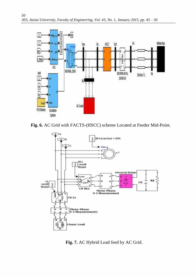
The Unified Study AC system configuration is shown in Fig. 6. This system comprises
a hybrid AC load of linear, converter type nonlinear and induction motor loads that
connected to the load bus as shown in Fig. 7.
5.1. Normal operations
Figs. (8-10) illustrate dynamic simulation responses of Power, Power Factor, Reactive
Power, RMS Voltage at Load bus in presence of HSCC FACTS controlled by HFLC and
PID controllers and without HSCC FACTS under normal operation conditions.
-0.1-0.05
00.05
0.1
-0.5
0
0.5-1
-0.5
0
0.5
1
ErrorError Rate
PD
Va
lue
-1
-0.5
0
0.5
1
-1
-0.5
0
0.5
1-1
-0.5
0
0.5
1
PD ValueIntegeral Error
Co
ntr
ol
Acti
on
; U
50
JES, Assiut University, Faculty of Engineering, Vol. 43, No. 1, January 2015, pp. 45 – 56
Fig. 6. AC Grid with FACTS-(HSCC) scheme Located at Feeder Mid-Point.
Fig. 7. AC Hybrid Load feed by AC Grid.

51
Abdel-Fattah Attia 1 and Adel M. Sharaf, A novel multistage fuzzy controller for facts ………………
0 0.1 0.2 0.3 0.4
0
0.2
0.4
0.6
0.8
1
1.2
1.4
1.6
Time (sec)
Activ
e Pow
er (p
u)
Gen. Bus
HFLC
MPID
Without
0 0.1 0.2 0.3 0.4
0
0.1
0.2
0.3
0.4
0.5
0.6
Time (sec)
Activ
e Pow
er (p
u)
Load Bus
HFLC
MPID
Without
0 0.1 0.2 0.3 0.4-0.2
0
0.2
0.4
0.6
0.8
1
Time (sec)
Powe
r Fac
tor
Load Bus
HFLC
MPID
Without
0 0.1 0.2 0.3 0.40.2
0.4
0.6
0.8
1
1.2
Time (sec)
Reac
tive
Powe
r (pu
)
Load Bus
HFLC
MPID
Without
0 0.1 0.2 0.3 0.40.4
0.6
0.8
1
1.2
1.4
Time (sec)
RMS
Volta
ge (p
u)
Load Bus
HFLC
MPID
Without
0 0.1 0.2 0.3 0.40.2
0.4
0.6
0.8
1
1.2
Time (sec)
RMS
Curre
nt
Load Bus
HFLC
MPID
Without
Fig. 8. Active Power at Generator and Load Buses.
Fig. 9. Power Factor and Reactive power at Load Bus.
Fig. 10. RMS Voltage and RMS current at Load Buses.
5.2. Load excursions
The AC system is examined under load excursion as the following:
Linear load rejected at time = 0.1-0.15 sec, Non-Linear load rejected at time = 0.2- 0.25
sec, Motor load Torque; Tm at =50 % at time = 0.3-0.35 sec and Motor load Torque; Tm at
=150% at time = 0.4-0.45 sec. Figs. (11-13) illustrate simulation responses of Power,
Power Factor, Reactive Power, RMS-Voltage at Load bus in presence of HSCC FACTS
controlled by HFLC and PID controllers and without HSCC FACTS.

52
JES, Assiut University, Faculty of Engineering, Vol. 43, No. 1, January 2015, pp. 45 – 56
Fig. 11. Active Power at Generator and Load Buses.
Fig. 12. Power Factor and Reactive power at Load Bus.
Fig. 13. RMS Voltage and RMS current at Load Buses.
5.3. Short circuit faults
The AC system is examined under short circuit fault for time = 0.2-0.3 at Vs bus. Figs.
(14-16) illustrate simulation responses of Power, Power Factor, Reactive Power, RMS-
Voltage at Load bus in presence of HSCC FACTS controlled by HFLC and PID
controllers and without HSCC FACTS.
0 0.1 0.2 0.3 0.4
-0.2
0
0.2
0.4
0.6
0.8
1
1.2
1.4
Time (sec)
Activ
e Po
wer (
pu)
Gen. Bus
HFLC
MPID
Without
0 0.1 0.2 0.3 0.4-0.2
0
0.2
0.4
0.6
0.8
1
1.2
Time (sec)
Activ
e Po
wer (
pu)
Load Bus
HFLC
MPID
Without
0 0.1 0.2 0.3 0.4
0
0.2
0.4
0.6
0.8
1
Time (sec)
Powe
r Fac
tor
Load Bus
HFLC
MPID
Without
0 0.1 0.2 0.3 0.4-0.2
0
0.2
0.4
0.6
0.8
1
1.2
1.4
Time (sec)
Reac
tive
Powe
r (pu
)
Load Bus
HFLC
MPID
Without
0 0.1 0.2 0.3 0.40
0.5
1
1.5
Time (sec)
RMS
Volta
ge (p
u)
Load Bus
HFLC
MPID
Without
0 0.1 0.2 0.3 0.4
-0.2
0
0.2
0.4
0.6
0.8
1
1.2
Time (sec)
RMS
Curre
nt
Load Bus
HFLC
MPID
Without

53
Abdel-Fattah Attia 1 and Adel M. Sharaf, A novel multistage fuzzy controller for facts ………………
Fig. 14. Active Power at Generator and Load Buses.
Fig. 15. Power Factor and Reactive power at Load Bus.
Fig. 16. RMS Voltage and RMS current at Load Buses.
5.4. Open circuit faults
The AC system is examined under open circuit fault for time = 0.2-0.3 at Vs bus. Figs.
(17-19) illustrate simulation responses of Power, Power Factor, Reactive Power, RMS
Voltage at Load bus in presence of HSCC FACTS controlled by HFLC and PID
controllers and without HSCC FACTS.
0 0.1 0.2 0.3 0.40
0.2
0.4
0.6
0.8
1
1.2
1.4
1.6
Appa
rent
Pow
er (p
u)
Time (sec)
HFLC
MPID
Without
0 0.1 0.2 0.3 0.4-0.8
-0.6
-0.4
-0.2
0
0.2
0.4
0.6
0.8
1
Powe
r Fac
tor
Time (sec)
HFLC
MPID
Without
0 0.1 0.2 0.3 0.4-1
-0.5
0
0.5
1
Time (sec)
Powe
r Fac
tor
Load Bus
HFLC
MPID
Without
0 0.1 0.2 0.3 0.4-0.2
0
0.2
0.4
0.6
0.8
1
1.2
Time (sec)
Reac
tive
Powe
r (pu
)
Load Bus
HFLC
MPID
Without
0 0.1 0.2 0.3 0.40
0.2
0.4
0.6
0.8
1
1.2
1.4
Time (sec)
RMS
Volta
ge (p
u)
Load Bus
HFLC
MPID
Without
0 0.1 0.2 0.3 0.40
0.2
0.4
0.6
0.8
1
1.2
1.4
Time (sec)
RMS
Curre
nt
Load Bus
HFLC
MPID
Without

54
JES, Assiut University, Faculty of Engineering, Vol. 43, No. 1, January 2015, pp. 45 – 56
0 0.1 0.2 0.3 0.40.6
0.7
0.8
0.9
1
1.1
1.2
1.3
Time (sec)
RMS
Volta
ge (p
u)
Load Bus
HFLC
MPID
Without
0 0.1 0.2 0.3 0.40
0.5
1
1.5
2
2.5
3
3.5
Time (sec)
RMS
Curre
nt
Load Bus
HFLC
MPID
Without
0 0.1 0.2 0.3 0.40
0.2
0.4
0.6
0.8
1
Time (sec)
Powe
r Fac
tor
Load Bus
HFLC
MPID
Without
0 0.1 0.2 0.3 0.40
0.2
0.4
0.6
0.8
1
1.2
Time (sec)
Reac
tive
Powe
r (pu
)
Load Bus
HFLC
MPID
Without
Fig. 17. Active Power at Generator and Load Buses.
Fig. 18. Power Factor and Reactive power at Load Bus.
Fig. 19. RMS Voltage and RMS current at Load Buses.
The system dynamic response under open circuit, short circuit and local generator load
switching changes for (100-200) milliseconds is generally compared and assessed for
ensuring continuous energy delivery over the feeder, reduced feeder losses, enhanced
active power delivery and reduced reactive demand on the AC generation. The transient
voltages and inrush currents are ensured to be minimum to allow for robust secure
operation without damage to FACTS switching devices and series and shunt capacitive
banks in comparison to normal operating conditions. The selected excursions and faults
duration of few cycles are typical to ensure operation without the activation of protection
gear and system isolation. The Performance-Index used is enhanced active power delivery,
reduced reactive power demand on the generator, reduced feeder losses and minimum
transient over voltages at key generator-system interface bus as well as reduced transient
recovery voltages and inrush current conditions on the hybrid FACTS Series and Shunt
capacitor banks and switching devices.
0 0.1 0.2 0.3 0.40
0.1
0.2
0.3
0.4
0.5
Time (sec)
Activ
e Po
wer (
pu)
Gen. Bus
HFLC
MPID
Without
0 0.1 0.2 0.3 0.40
0.1
0.2
0.3
0.4
0.5
Time (sec)
Activ
e Po
wer (
pu)
Load Bus
HFLC
MPID
Without

55
Abdel-Fattah Attia 1 and Adel M. Sharaf, A novel multistage fuzzy controller for facts ………………
6. Conclusions
The paper presents a novel hybrid FACTS Based Voltage stabilization, efficient energy
utilization and feeder Loss reduction scheme for smart grid systems. Transient over
voltages and inrush currents are also reduced. The two-stage hierarchical fuzzy logic
control scheme utilized a tri-regulation multi loop error tracking. The dynamic HFLC
controller is utilized to reduce the number of fuzzy rules to a linear function of input
variables to allow designing an multi task HFLC control scheme where a global task is
divided into sub-levels, hence allowing task-design an independently at each sub-level. A
final coordinating strategy is used for optimizing the subtask-controllers to achieve the
global tracking/stabilization objective. Digital simulation results validate the proposed
control scheme effectiveness and robustness with Efficient Energy Utilization, reduced
reactive demand, minimal transient over voltages, reduced inrush conditions , improved
power quality and Power Factor at the generator, load and AC system interface Buses. The
same FACTS hybrid filter-compensator scheme is now tested for Dynamic Voltage
Regulation and Loss reduction in Smart grid distribution and Utilization grid Systems.
APPENDIX
Steam Turbine: Pout=600MW, Speed=3600 rpm.
Synchronous
Generator:
3Ph., 2 poles
Vg=25 KV (L-L), Sg= 600MVA
Xd=1.79 pu Xd'=0.169 pu Xd''=0.135 pu
Xq=1.71pu Xq'=0.228pu Xq''=0.2pu
X1=0.13 pu
Transmission line: 500 KV (L-L), 300km
R/km=0.01273Ω, L/km=0.9337mH
Infinite Bus: 500KV
HSCC Parameters: Cf1= Cf2=250μf
CL=15μf , Rf=1.5Ω, Lf=3 mH
SPWM: P2= P3= 1P ,Fs/w = 1750 Hz
HFLC linguistic variables :
mf: membership function.
NL; Negative Large.
NS; Negative Small.
Z; Zero.
PS; Positive Small.
PL; Large.
Tri-Loop:
T1=5 ms
T2=10 ms
T3=5 ms
T4=20 ms
T5=30 ms
T6=20 ms
Delay=5-10 ms
Vg=1
Pg=0.25
Ig=0.5
Vg_rep=1
Pg_rep =1
Ig_rep =0.5
Kc=1
Controller gains:
Kp=0-15 , Ki=0-1;
Kd=0-1, Ke=0-1
PDFLC PIDFLC
Input variables:
Global error (et) and
change of error(ét).
Output variable:
PD value.
Input
variables:
PD valueand
the error
integrator et.
Output
variable:
The output
signal (U)

56
JES, Assiut University, Faculty of Engineering, Vol. 43, No. 1, January 2015, pp. 45 – 56
REFERENCES
[1] Chandra, B. Singh, B.N. Singh, K. Al-Haddad, "An Improved Control Algorithm of Shunt
Active Filter for Voltage Regulation, Harmonic Elimination, Power Factor Correction, and
Balancing of Nonlinear Loads", IEEE Trans. on Power Electronics, Vol. 15, No. 3, May
2000, pp.495-507.
[2] A. M. Sharaf, and G. Wang, "Wind Energy System Voltage and Energy Enhancement using
Low Cost Dynamic Capacitor Compensation Scheme." Proceedings of the IEEE
International Conference on Electrical, Electronic and Computer Engineering. pp. 804-807,
5-7 Sept. 2004.
[3] A. M. Sharaf and K. M. Abo-Al-Ez, "A FACTS based dynamic capacitor scheme for voltage
compensation and power quality enhancement," 2006 IEEE International Symposium on
Industrial Electronics, vol. 2, pp. 1200-1205, 2006.
[4] A. M. Sharaf, B., Khaki, "A FACTS based switched capacitor compensation scheme for
smart grid applications", Innovations in Intelligent Systems and Applications (INISTA),
2012 International Symposium on, page(s): 1 – 5.
[5] A. M. Sharaf and R. Chhetri, "A novel dynamic capacitor compensator/green plug scheme
for 3-phase 4-wire utilization loads," Canadian Conference on Electrical and Computer
Engineering, 2006, CCECE '06, pp. 454-459, 2006.
[6] A. Bagis "Tabu search algorithm based PID controller tuning for desired system
specifications." Journal of the Franklin Institute, 348 (2011), pp. 2795–2812
[7] Z. L. Gaing, "A Particle Swarm Optimization Approach for Optimum Design of PID
Controller in AYR System", IEEE T ENERGY CONVER, Vol.9 (2), Jun. 2004, pp.: 384-
391.
[8] A. -F. Attia, H. Soliman, and M. Sabry. "Genetic Algorithm Based Control System Design of
a Self-Excited Induction Generator." Acta Polytechnica 46 (2), 11-22, 2006.
[9] A. -F. Attia, "Hierarchical fuzzy controllers for an astronomical telescope tracking." APPL
SOFT COMPUT. 9.1 (2009): 135-141.
[10] A. M. Sharaf, R. Chhetri, "A novel dynamic capacitor compensator/green plug scheme for
3-phase 4-wire utilization loads", IEEE-CCECE, Ottawa, Ontario, Canada 2006.
[11] A. M. Sharaf, A. Aljankawey and I. H. Altas "A novel voltage stabilization control Scheme
for stand-alone wind energy conversion systems", Proc. Conf. Clean Elect. Power,
ICCEP2007, pp.514 -519, 2007.
[12] A. M. Sharaf, M.Z El-Sadek, F.N Abd-Elbar, A.M Hemeida. "A global dynamic error
driven control scheme for static VAR compensators." EPSR, 51 (2), 131-141, 1999.
[13] F.L. Chung, J.C. Duan, On multistage fuzzy neural network modeling, IEEE Trans. Fuzzy
Syst. 8 (2) (2000) 125–142.
[14] J. M. Adams, K. S. Rattan, "Intelligent control of a direct-drive robot using multi-stage
fuzzy logic", Proc. of the 44th IEEE Midwest Symposium on Circuits and Systems, Vol.2,
2001, pp.543-546
[15] H. P. Chen and T. M. Pamg "A new approach of multistage fuzzy logic inference", Fuzzy
Sets and Systems, vol. 78, pp.51 -72, 1996.
Recommended


![INTERNATIONAL JOURNAL OF COMPUTERS AND … · logic. Four Fuzzy Logic Controller are used to navigate the mobile robot in [22]. These four fuzzy controls form a hierarchical control](https://img.pdfslide.net/doc/110x75/5eda087abb309434ee032342/international-journal-of-computers-and-logic-four-fuzzy-logic-controller-are-used.jpg)