International Journal of Computer Applications (0975 – 8887)
Volume 128 – No2, October 2015
27
A Review on Reversible Logic Gates and it’s QCA
Implementation
Mohammad Abdullah-Al-Shafi
Dept of ICT Mawlana Bhashani Science and Technology University
Tangail, Bangladesh
Md Shifatul Islam Dept of ICT
Mawlana Bhashani Science and Technology University
Tangail, Bangladesh
Ali Newaz Bahar Dept of ICT
Mawlana Bhashani Science and Technology University
Tangail, Bangladesh
ABSTRACT
Quantum Dot Cellular Automata (QCA) is a rising innovation
which seems to be a good competitor for the next generation
of digital systems and widely utilized as a part of advanced
frameworks. It is an appealing substitute to ordinary CMOS
innovation because of diminutive size, faster speed, extremely
scalable feature, ultralow power consumption and better
switching frequency. The realization of quantum computation
is not possible without reversible logic. Reversible logic has
enlarged operations in quantum computation. Generally
reversible computing is executed when system composes of
reversible gates. It has numerous fields of use as applied
science, quantum dot cellular automata as well as low power
VLSI circuits, low power CMOS, digital signal processing,
computer graphics. In this paper, the quantum implementation
of primitive reversible gate has been presented. The proposed
gates have been designed and simulated using QCADesigner.
General Terms
Quantum Cellular Automata and Reversible Logic Gates
Keywords
Quantum-dot Cellular Automata (QCA), Reversible logic,
Reversible gates, QCA Designer
1. INTRODUCTION Nanotechnology allows new measurements for computing as
typical silicon transistor technology faces disparate
complication due to its speed, power utilization and
challenges in feature size diminishment. Among promising
technologies, Quantum dot Cellular Automata (QCA) [1, 2]
assurance aforementioned components. Quantum Dot Cellular
Automata (QCA) has been utilized widely and wipes out these
issues. Quantum Dot Cellular Automata (QCA) is a
productive substitute of Complementary metal oxide
semiconductor (CMOS) innovation [3]. QCA is a combined
strategy for transmission and computation [4, 5, 6]. The
reversible logic circuits design the key structural engineering
of quantum computers as all quantum processes are
reversible. Efficiency loss is a vital consideration in planning
digital framework. Energy loss because of data fall in circuits
and systems constructed using irreversible logic circuit was
exhibited by R. Landauer. From Landauer’s principle, the loss
of one bit of information lost, will exhaust kTln(2) joules of
vitality where k=1.38x10⁻²³ JK-1 is the Boltzmann’s constant
and T is supreme temperature in Kelvin [7]. Bennett
demonstrate that to sidestep kTln2 joules of vitality
dissipation in a circuit, it must be manufactured from
reversible circuits [8]. In reversible logic circuits information
fall is not feasible so it is preferable to form combinational
circuit. Reversible logic circuits are of high enthusiasm for
nano innovation [9], quantum computing [10] and optical
computing [11]. An exceptional utilization of reversible logic
circuit lies in quantum computers [12]. Number of input and
output is identical in reversible logic gate to have one to one
mapping. Classical logic combination procedures cannot be
directly connected to model reversible circuit. An imperative
parameter of a reversible logic circuit is garbage output.
Generally an unutilized product from a gate is garbage. The
quantum cost is a cost that is associated with every reversible
logic gate. In this paper, mostly available reversible logic
gates and their QCA design are presented.
2. BASIC TERMS RELATED TO
REVERSIBLE LOGIC A. Reversible Function: The Boolean function F(x1; x2,...xn)
with multiple output of n Boolean variables is called
reversible if the number of output is identical to number of
inputs. Any output pattern has a unique pre-image.
Particularly, reversible functions are those that execute
permutations of the set of input vectors [13].
B. Reversible logic: In reversible logic, the numbers of input
are equal to number the outputs of the gates. This generates
particular set of output vector for each set of input vector.
C. Garbage outputs: Additional inputs or outputs can be added
so as to make the number of inputs and outputs identical
whenever required. The number of outputs added to make an
m-input-k-output function ((m;k)function) reversible is called
garbage. The formula between the number of garbage outputs
and constant inputs are shown below –
Input + constant input = output + garbage
An output line that is necessary to sustain the reversibility is
referred as garbage line [14].
D. Quantum Cost: Quantum cost refers the amount of effort
needed to transform a reversible circuit to a quantum circuit.
It is calculated knowing the number of primitive reversible
logic gates needed to recognize the circuit.
E. Ancilla inputs: Ancilla inputs or constant inputs is the
number of inputs which are maintain constant either 0 or 1 in
order to incorporate the given logical function [15].
F. Flexibility: Flexibility is the universality of a reversible
logic gate for realizing more functions [16].
G. Gate level: In the circuit gate level is the number of levels
that are needed to recognize the given logic functions.
H. Hardware complexity: Hardware Complexity is the overall
number of logic action in a circuit. In other words the total
number of AND, OR and EXOR operation in a circuit [17,
18].
International Journal of Computer Applications (0975 – 8887)
Volume 128 – No2, October 2015
28
3. QCA BASIC The primary architecture block of QCA is QCA cell. It can be
viewed as an arrangement of four dots located at corners of a
square [19]. Depending on the electron's location, QCA cell
has two form of polarization, binary 1 or P = +1.00 and binary
0 or P = -1.00 [17] shown in figure 1. QCA offer an
innovative distinct option for the transistor paradigm [20, 21].
The cell polarization defined as follows:
P=
(1)
Where, the electronic charge denoted as ρi
Fig 1: Four doted QCA cell
3.1 QCA Wire
QCA wire is a combination of interconnected QCA cells with
similar polarization. It used to carry signal from one direction
to another. Therefore QCA wires can propagate data from one
side to another [22].
Fig 2: QCA wire
3.2 QCA Inverter
QCA inverter returns the reversed value of the input one and
it consists of four QCA wire shown in figure 3.
Fig 3: QCA inverter
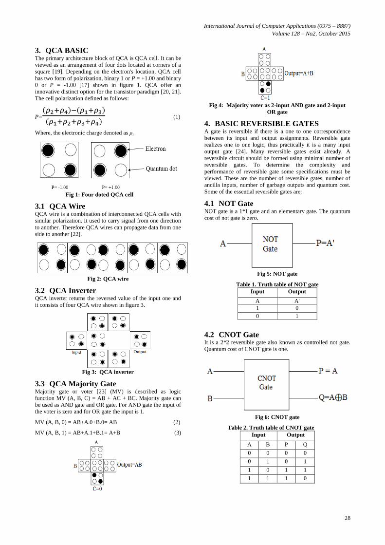
3.3 QCA Majority Gate
Majority gate or voter [23] (MV) is described as logic
function MV (A, B, C) = AB + AC + BC. Majority gate can
be used as AND gate and OR gate. For AND gate the input of
the voter is zero and for OR gate the input is 1.
MV (A, B, 0) = AB+A.0+B.0= AB (2)
MV (A, B, 1) = AB+A.1+B.1= A+B (3)
Fig 4: Majority voter as 2-input AND gate and 2-input
OR gate
4. BASIC REVERSIBLE GATES A gate is reversible if there is a one to one correspondence
between its input and output assignments. Reversible gate
realizes one to one logic, thus practically it is a many input
output gate [24]. Many reversible gates exist already. A
reversible circuit should be formed using minimal number of
reversible gates. To determine the complexity and
performance of reversible gate some specifications must be
viewed. These are the number of reversible gates, number of
ancilla inputs, number of garbage outputs and quantum cost.
Some of the essential reversible gates are:
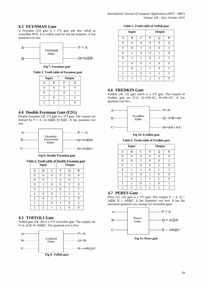
4.1 NOT Gate
NOT gate is a 1*1 gate and an elementary gate. The quantum
cost of not gate is zero.
Fig 5: NOT gate
Table 1. Truth table of NOT gate
Input Output
A A'
1 0
0 1
4.2 CNOT Gate
It is a 2*2 reversible gate also known as controlled not gate.
Quantum cost of CNOT gate is one.
Fig 6: CNOT gate
Table 2. Truth table of CNOT gate
Input Output
A B P Q
0 0 0 0
0 1 0 1
1 0 1 1
1 1 1 0
International Journal of Computer Applications (0975 – 8887)
Volume 128 – No2, October 2015
29
4.3 FEYNMAN Gate A Feynman [25] gate is a 2*2 gate and also called as
controlled NOT. It is widely used for fan-out purposes. It has
quantum cost one.
Fig 7: Feynman gate
Table 3. Truth table of Feynman gate
4.4 Double Feynman Gate (F2G) Double Feynman [26, 27] gate is a 3*3 gate. The outputs are
defined by P = A, Q=A⊕B, R=A⊕C. It has quantum cost
two.
Fig 8: Double Feynman gate
Table 4. Truth table of Double Feynman gate
Input Output
A B C P Q R
0 0 0 0 0 0
0 0 1 0 0 1
0 1 0 0 1 0
0 1 1 0 1 1
1 0 0 1 1 1
1 0 1 1 1 0
1 1 0 1 0 1
1 1 1 1 0 0
4.5 TOFFOLI Gate Toffoli gate [28, 29] is a 3*3 reversible gate. The outputs are
P=A, Q=B, R=AB⊕C. The quantum cost is five.
Fig 9: Toffoli gate
Table 5. Truth table of Toffoli gate Input Output
A B C P Q R
0 0 0 0 0 0
0 0 1 0 0 1
0 1 0 0 1 0
0 1 1 0 1 1
1 0 0 1 0 0
1 0 1 1 0 1
1 1 0 1 1 1
1 1 1 1 1 0
4.6 FREDKIN Gate Fredkin [30, 31] gate which is a 3*3 gate. The outputs of
Fredkin gate are P=A, Q=A'B+AC, R=AB+A'C. It has
quantum cost five.
Fig 10: Fredkin gate
Table 6. Truth table of Fredkin gate Input Output
A B C P Q R
0 0 0 0 0 0
0 0 1 0 0 1
0 1 0 0 1 0
0 1 1 0 1 1
1 0 0 1 0 0
1 0 1 1 1 0
1 1 0 1 0 1
1 1 1 1 1 1
4.7 PERES Gate Peres [32, 33] gate is a 3*3 gate. The outputs P = A, Q =
A⊕B, R = AB⊕C. It has Quantum cost four. It has the
minimum quantum cost, among 3x3 reversible gates.
Fig 11: Peres gate
Input Output
A B P Q
0 0 0 0
0 1 0 1
1 0 1 1
1 1 1 0
International Journal of Computer Applications (0975 – 8887)
Volume 128 – No2, October 2015
30
Table 7. Truth table of Peres gate Input Output
A B C P Q R
0 0 0 0 0 0
0 0 1 0 0 1
0 1 0 0 1 0
0 1 1 0 1 1
1 0 0 1 1 0
1 0 1 1 1 1
1 1 0 1 0 1
1 1 1 1 0 0
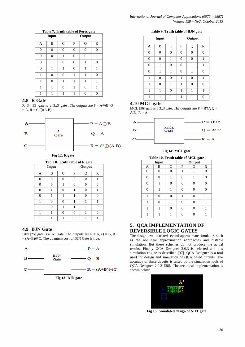
4.8 R Gate R [34, 35] gate is a 3x3 gate . The outputs are P = A⊕B, Q
= A, R = C'⊕(A.B)
Fig 12: R gate
Table 8. Truth table of R gate
Input Output
A B C P Q R
0 0 0 0 0 1
0 0 1 0 0 0
0 1 0 1 0 1
0 1 1 1 0 0
1 0 0 1 1 1
1 0 1 1 1 0
1 1 0 0 1 0
1 1 1 0 1 1
4.9 BJN Gate BJN [25] gate is a 3x3 gate. The outputs are P = A, Q = B, R
= (A+B)⊕C. The quantum cost of BJN Gate is five.
Fig 13: BJN gate
Table 9. Truth table of BJN gate
Input Output
A B C P Q R
0 0 0 0 0 0
0 0 1 0 0 1
0 1 0 0 1 1
0 1 1 0 1 0
1 0 0 1 0 1
1 0 1 1 0 0
1 1 0 1 1 1
1 1 1 1 1 0
4.10 MCL gate MCL [36] gate is a 3x3 gate. The outputs are P = B'C', Q =
A'B', R = A.
Fig 14: MCL gate Table 10. Truth table of MCL gate
Input Output
A B C P Q R
0 0 0 1 1 0
0 0 1 0 1 0
0 1 0 0 0 0
0 1 1 0 0 0
1 0 0 1 0 1
1 0 1 0 0 1
1 1 0 0 0 1
1 1 1 0 0 1
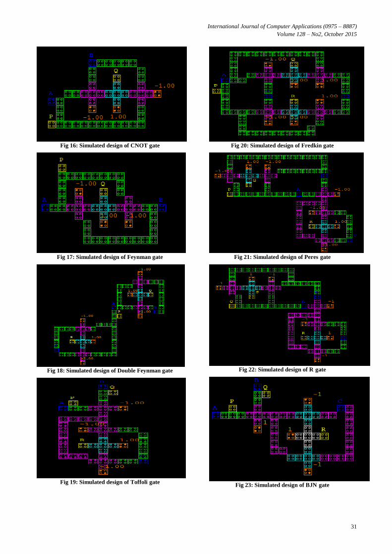
5. QCA IMPLEMENTATION OF
REVERSIBLE LOGIC GATES The design level is tested several approximate simulators such
as the nonlinear approximation approaches and bistable
simulation. But these schemes do not produce the actual
results. Finally QCA Designer 2.0.3 is selected and this
simulation engine is described [37]. QCA Designer is a tool
used for design and simulation of QCA based circuits. The
accuracy of these circuits is tested by the simulation tools of
QCA Designer 2.0.3 [38]. The technical implementation is
shown below.
Fig 15: Simulated design of NOT gate
International Journal of Computer Applications (0975 – 8887)
Volume 128 – No2, October 2015
31
Fig 16: Simulated design of CNOT gate
Fig 17: Simulated design of Feynman gate
Fig 18: Simulated design of Double Feynman gate
Fig 19: Simulated design of Toffoli gate
Fig 20: Simulated design of Fredkin gate
Fig 21: Simulated design of Peres gate
Fig 22: Simulated design of R gate
Fig 23: Simulated design of BJN gate
International Journal of Computer Applications (0975 – 8887)
Volume 128 – No2, October 2015
32
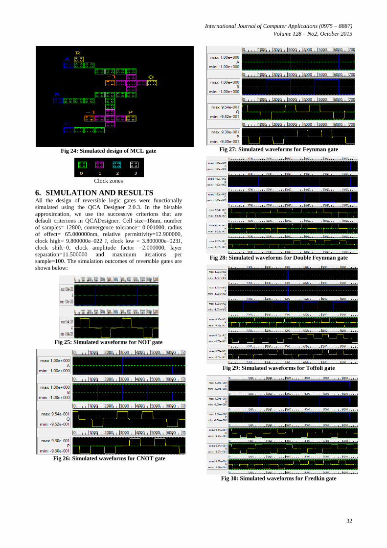
Fig 24: Simulated design of MCL gate
Clock zones
6. SIMULATION AND RESULTS All the design of reversible logic gates were functionally
simulated using the QCA Designer 2.0.3. In the bistable
approximation, we use the successive criterions that are
default criterions in QCADesigner. Cell size=18nm, number
of samples= 12800, convergence tolerance= 0.001000, radius
of effect= 65.000000nm, relative permittivity=12.900000,
clock high= 9.800000e–022 J, clock low = 3.800000e–023J,
clock shift=0, clock amplitude factor =2.000000, layer
separation=11.500000 and maximum iterations per
sample=100. The simulation outcomes of reversible gates are
shown below:
Fig 25: Simulated waveforms for NOT gate
Fig 26: Simulated waveforms for CNOT gate
Fig 27: Simulated waveforms for Feynman gate
Fig 28: Simulated waveforms for Double Feynman gate
Fig 29: Simulated waveforms for Toffoli gate
Fig 30: Simulated waveforms for Fredkin gate
International Journal of Computer Applications (0975 – 8887)
Volume 128 – No2, October 2015
33
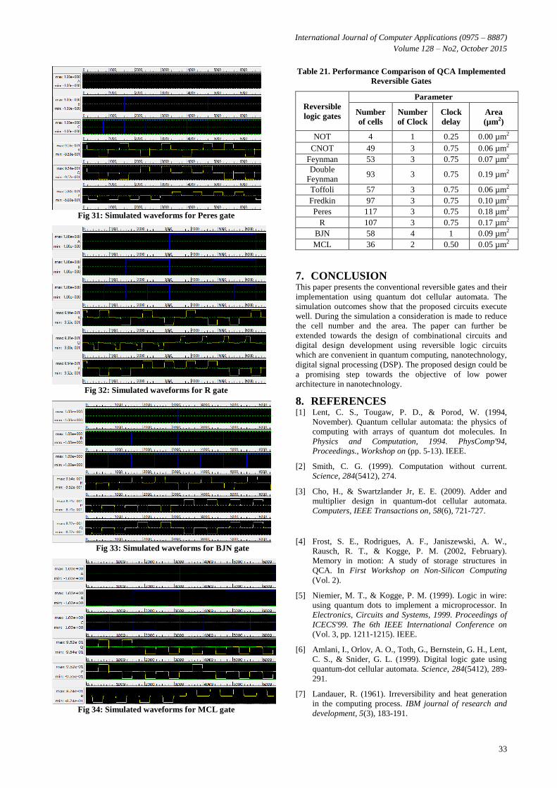
Fig 31: Simulated waveforms for Peres gate
Fig 32: Simulated waveforms for R gate
Fig 33: Simulated waveforms for BJN gate
Fig 34: Simulated waveforms for MCL gate
Table 21. Performance Comparison of QCA Implemented
Reversible Gates
Reversible
logic gates
Parameter
Number
of cells
Number
of Clock
Clock
delay
Area
(µm2)
NOT 4 1 0.25 0.00 µm2
CNOT 49 3 0.75 0.06 µm2
Feynman 53 3 0.75 0.07 µm2
Double
Feynman 93 3 0.75 0.19 µm2
Toffoli 57 3 0.75 0.06 µm2
Fredkin 97 3 0.75 0.10 µm2
Peres 117 3 0.75 0.18 µm2
R 107 3 0.75 0.17 µm2
BJN 58 4 1 0.09 µm2
MCL 36 2 0.50 0.05 µm2
7. CONCLUSION This paper presents the conventional reversible gates and their
implementation using quantum dot cellular automata. The
simulation outcomes show that the proposed circuits execute
well. During the simulation a consideration is made to reduce
the cell number and the area. The paper can further be
extended towards the design of combinational circuits and
digital design development using reversible logic circuits
which are convenient in quantum computing, nanotechnology,
digital signal processing (DSP). The proposed design could be
a promising step towards the objective of low power
architecture in nanotechnology.
8. REFERENCES [1] Lent, C. S., Tougaw, P. D., & Porod, W. (1994,
November). Quantum cellular automata: the physics of
computing with arrays of quantum dot molecules. In
Physics and Computation, 1994. PhysComp'94,
Proceedings., Workshop on (pp. 5-13). IEEE.
[2] Smith, C. G. (1999). Computation without current.
Science, 284(5412), 274.
[3] Cho, H., & Swartzlander Jr, E. E. (2009). Adder and
multiplier design in quantum-dot cellular automata.
Computers, IEEE Transactions on, 58(6), 721-727.
[4] Frost, S. E., Rodrigues, A. F., Janiszewski, A. W.,
Rausch, R. T., & Kogge, P. M. (2002, February).
Memory in motion: A study of storage structures in
QCA. In First Workshop on Non-Silicon Computing
(Vol. 2).
[5] Niemier, M. T., & Kogge, P. M. (1999). Logic in wire:
using quantum dots to implement a microprocessor. In
Electronics, Circuits and Systems, 1999. Proceedings of
ICECS'99. The 6th IEEE International Conference on
(Vol. 3, pp. 1211-1215). IEEE.
[6] Amlani, I., Orlov, A. O., Toth, G., Bernstein, G. H., Lent,
C. S., & Snider, G. L. (1999). Digital logic gate using
quantum-dot cellular automata. Science, 284(5412), 289-
291.
[7] Landauer, R. (1961). Irreversibility and heat generation
in the computing process. IBM journal of research and
development, 5(3), 183-191.
International Journal of Computer Applications (0975 – 8887)
Volume 128 – No2, October 2015
34
[8] Bennett, C. H. (1973). Logical reversibility of
computation. IBM journal of Research and Development,
17(6), 525-532.
[9] Merkle, R. C. (1993). Two types of mechanical
reversible logic. Nanotechnology, 4(2), 114.
[10] Nielsen, M. A., & Chuang, I. L. (2010). Quantum
computation and quantum information. Cambridge
university press.
[11] Knill, E., Laflamme, R., & Milburn, G. J. (2001). A
scheme for efficient quantum computation with linear
optics. Nature, 409(6816), 46-52.
[12] Vedral, V., Barenco, A., & Ekert, A. (1996). Quantum
networks for elementary arithmetic operations. Physical
Review A, 54(1), 147.
[13] Raghu kanth, B., Murali Krishna, B., Sridhar, M., and
Santhi Swaroop, V.G. (2012). A Distinguish Between
Reversible and Conventional Logic Gates. International
Journal of Engineering Research and Applications, 2(2),
148-151.
[14] Saeedi, M., & Markov, I. L. (2013). Synthesis and
optimization of reversible circuits-a survey. ACM
Computing Surveys (CSUR), 45(2), 21.
[15] Thapliyal, H., & Ranganathan, N. (2010). Design of
reversible sequential circuits optimizing quantum cost,
delay, and garbage outputs. ACM Journal on Emerging
Technologies in Computing Systems (JETC), 6(4), 14.
[16] Bhagyalakshmi, H. R., & Venkatesha, M. K. (2010).
Optimized reversible BCD adder using new reversible
logic gates. arXiv preprint arXiv:1002.3994.
[17] Haghparast, M., & Navi, K. (2008). A novel reversible
BCD adder for nanotechnology based systems. American
Journal of Applied Sciences, 5(3), 282-288.
[18] Sayem, A. S. M., & Ueda, M. (2010). Optimization of
reversible sequential circuits. arXiv preprint
arXiv:1006.4570.
[19] Tougaw, P. D., & Lent, C. S. (1994). Logical devices
implemented using quantum cellular automata. Journal
of Applied physics, 75(3), 1818-1825.
[20] Lent, C. S., & Tougaw, P. D. (1997). A device
architecture for computing with quantum dots.
Proceedings of the IEEE, 85(4), 541-557.
[21] Benjamin, S. C., & Johnson, N. F. (1997). A possible
nanometer-scale computing device based on an adding
cellular automaton. Applied Physics Letters, 70(17),
2321-2323.
[22] Roohi, A., Khademolhosseini, H., Sayedsalehi, S., &
Navi, K. (2011). A novel architecture for quantum-dot
cellular automata multiplexer. International Journal of
Computer Science Issues, 8(1).
[23] Imre, A., Csaba, G., Ji, L., Orlov, A., Bernstein, G. H., &
Porod, W. (2006). Majority logic gate for magnetic
quantum-dot cellular automata. Science, 311(5758), 205-
208.
[24] Morita, K. (2008). Reversible computing and cellular
automata—A survey. Theoretical Computer Science,
395(1), 101-131.
[25] Bahar, A.N., Waheed, S., and Habib, M.A. 2014. A
novel presentation of reversible logic gate in Quantum-
dot Cellular Automata (QCA). 1st International
Conference on Electrical Engineering and Information
Communication Technology (ICEEICT), IEEE, 1-6.
[26] Parhami, B. (2006, October). Fault-tolerant reversible
circuits. In Signals, Systems and Computers, 2006.
ACSSC'06. Fortieth Asilomar Conference on (pp. 1726-
1729). IEEE.
[27] Bahar, A.N., Waheed, S., Uddin, M, A., and Habib, M.A.
(2013). Double Feynman Gate (F2G) in Quantum-dot
Cellular Automata (QCA). International Journal of
Computer Science Engineering, 2(6), 351-355.
[28] Toffoli, T. (1980). Reversible computing Tech memo
MIT. M IT/LCS/TM-151, MIT Lab for Comp. Sci.
[29] Bahar, A. N., Habib, M., & Biswas, N. K. (2013). A
novel presentation of toffoli gate in quantum-dot cellular
automata (QCA). Int J Comput Appl, 82(10), 1-4.
[30] Toffoli, T. (1980). Reversible computing (pp. 632-644).
Springer Berlin Heidelberg.
[31] Bahar, A. N., Waheed, S., & Habib, M. A. (2015). An
Efficient Layout Design of Fredkin Gate in Quantum-dot
Cellular Automata (QCA). Düzce Üniversitesi Bilim ve
Teknoloji Dergisi, 3(1), 219-225.
[32] Peres, A. (1985). Reversible logic and quantum
computers. Physical review A, 32(6), 3266.
[33] Sarker, A., Bahar, A.N., Biswas, P.K., and Morshed, M.
(2014). A Novel Presentation of Peres Gate (PG) in
Quantum-Dot Cellular Automata (QCA), European
Scientific Journal. 10 (21), 101-106.
[34] Vasudevan, D. P., Lala, P. K., Di, J., & Parkerson, J. P.
(2006). Reversible-logic design with online testability.
Instrumentation and Measurement, IEEE Transactions
on, 55(2), 406-414.
[35] Bahar, A. N., Waheed, S., & Hossain, N. (2015). A new
approach of presenting reversible logic gate in nanoscale.
SpringerPlus, 4(1), 153.
[36] Islam, S., Farzana, S., & Ali Newaz Bahar, S. (2014).
Area Efficient layout design of Multiply Complements
Logic (MCL) Gate using QCA Technology. Global
Journal of Researches in Engineering, 14(4), 7-10.
[37] Walus, K., Dysart, T. J., Jullien, G., & Budiman, R. A.
(2004). QCADesigner: A rapid design and simulation
tool for quantum-dot cellular automata. Nanotechnology,
IEEE Transactions on, 3(1), 26-31.
[38] "QCADesigner "http://www.mina.ubc.ca/qcadesigner
(accessed April 2015).
IJCATM : www.ijcaonline.org
Recommended