A SUMMARY OF DISCRETE-ELEMENT METHODS OF ANALYSIS FOR PAVEMENT SLABS
by
w. Ronald Hudson Harvey J. Treybig Adnan Abou-Ayyash
Research Report Number 56-27
Development of Methods for Computer Simulation of Beam-Columns and Grid-Beam and Slab Systems
Research Project 3-5-63-56
conducted for
The Texas Highway Department
in cooperation with the U. S. Department of Transportation
Federal Highway Administration
by the
CENTER FOR HIGHWAY RESEARCH
THE UNIVERSITY OF TEXAS AT AUSTIN
August 1972

The contents of this report reflect the views of the authors, who are responsible for the facts and the accuracy of the data presented herein. The contents do not necessarily reflect the official views or policies of the Federal Highway Administration. This report does not constitute a standard, specification, or regulation.
ii
PREFACE
This report describes a comprehensive summary of discrete-element methods
of analysis for pavement slabs. It includes all the previous work related to
pavement design and analysis, as well as other proposed applications.
This is the twenty-seventh in a series of reports that describes the work
done in Research Project 3-5-63-56, entitled '~evelopment of Methods for Com
puter Simulation of Beam-Columns and Grid-Beam and Slab Systems." The project
is divided into two parts, one concerned primarily with bridge structures and
the other with pavement slabs, and this is the ninth report in the series that
deals directly with pavement slabs.
We are grateful to the entire staff of the Center for Highway Research,
who provided support during the preparation of this report. The contributions
herein of example work done by others which illustrate the wide applicability
of SLAB methods are also appreciated. They, of course, did not involve ex
penditure of project funds.
This project is sponsored by the Texas Highway Department in cooperation
with the U. S. Department of Transportation Federal Highway Administration.
August 1972
iii
W. Ronald Hudson
Harvey J. Treybig
Adnan Abou-Ayyash
LIST OF REPORTS
Report No. 56-1, "A Finite-Element Method of Solution for Linearly Elastic Beam-Columns" by Hudson Matlock and T. Allan Haliburton, presents a solution for beam-columns that is a basic tool in subsequent reports. September 1966.
Report No. 56-2, "A Computer Program to Analyze Bending of Bent Caps" by Hudson Matlock and Wayne B. Ingram, describes the application of the beamcolumn solution to the particular problem of bridge bent caps. October 1966.
Report No. 56-3, "A Finite-Element Method of Solution. for Structural Frames" by Hudson Matlock and Berry Ray Grubbs, describes a solution for frames with no sway. May 1967.
Report No. 56-4, "A Computer Program to Analyze Beam-Colmnns under Movable Loads" by Hudson Matlcok and Thomas P. Taylor, describes the application of the beam-column solution to problems with any configuration of movable nondynamic loads. June 1968.
Report No. 56-5, "A Finite-Element Method for Bending Analysis of Layered Structural Systems" by Wayne B. Ingram and Hudson Matlock, describes an alternating-direction iteration method for solving two-dimensional systems of layered grids-aver-beams and plates-aver-beams. June 1967.
Report No. 56-6, ''Discontinuous Orthotropic Plates and Pavement Slabs" by W. Ronald Hudson and Hudson Matlock, describes an alternating-direction iteration method for solving complex two-dimensional plate and slab problems with emphasis on pavement slabs. May 1966.
Report No. 56-7, "A Finite-Element Analysis of Structural Frames" by T. Allan Haliburton and Hudson Matlock, describes a method of analysis for rectangular plane frames with three degrees of freedom at each joint. July 1967.
Report No. 56-8, "A Finite-Element Method for Transverse Vibrations of Beams and Plates" by Harold Salani and Hudson Matlock, describes an implicit procedure for determining the transient and steady-state vibrations of beams and plates, including pavement slabs. June 1968.
Report No. 56-9, "A Direct Computer Solution for Plates and Pavement Slabs" by C. Fred Stelzer, Jr., and W. Ronald Hudson, describes a direct method for solving complex two-dimensional plate and slab problems. October 1967.
Report No. 56-10, "A Finite-Element Method of Analysis for Composite Beams" by Thomas P. Taylor and Hudson Matlock, describes a method of analysis for composite beams with any degree of horizontal shear interaction. January 1968.
iv
Report No. 56-11, "A Discrete-Element Solution of plates and Pavement Slabs Using a Variab1e-Increment-Length Model" by Charles M. Pearre, III, and W. Ronald Hudson, presents a method for solving freely discontinuous plates and pavement slabs subjected to a variety of loads. April 1969.
v
Report No. 56-U, "A Discrete-Element Method of Analysis for Combined Bending and Shear Deformations of a Beam" by David F. Tankersley and William P. Dawkins, presents a method of analysis for the combined effects of bending and shear deformations. December 1969.
Report No. 56-13, "A Discrete-Element Method of Multiple-Loading Analysis for Two-Way Bridge Floor Slabs" by John J. Panak and Hudson Matlock, includes a procedure for analysis of two-way bridge floor slabs continuous over many supports. January 1970.
Report No. 56-14, "A Direct Computer Solution for Plane Frames" by William P. Dawkins and John R. Ruser, Jr., presents a direct method of solution for the computer analysis of plane frame structures. May 1969.
Report No. 56-15, '~xperimenta1 Verification of Discrete-Element Solutions for Plates and Slabs" by Sohan L. Agarwal and W. Ronald Hudson, presents a comparison of discrete-element solutions with small-dimension test results for plates and slabs, including some cyclic data. April 1970.
Report No. 56-16, "Experimental Evaluation of Subgrade Modulus and Its Application in Model Slab Studies" by Qaiser S. Siddiqi and W. Ronald Hudson, describes a series of experiments to evaluate layered foundation coefficients of subgrade reaction for use in the discrete-element method. January 1970.
Report No. 56-17, '~ynamic Analysis of Discrete-Element Plates on Nonlinear Foundations" by Allen E. Kelly and Hudson Matlock, presents a numerical method for the dynamic analysis of plates on nonlinear foundations. July 1970.
Report No. 56-18, "A Discrete-Element Analysis for Anisotropic Skew Plates and Grids" by Mahendrakumar R. Vora and Hudson Matlock, describes a tridirectiona1 model and a computer program for the analysis of anisotropic skew plates or slabs with grid-beams. August 1970.
Report No. 56-19, "An Algebraic Equation Solution Process Formulated in Anticipation of Banded Linear Equations" by Frank L. Endres and Hudson Matlock, describes a system of equation-solving routines that may be applied to a wide variety of problems by using them within appropriate programs. January 1971.
Report No. 56-20, ''Finite-Element Method of Analysis for plane Curved Girders" by William P. Dawkins, presents a method of analysis that may be applied to plane-curved highway bridge girders and other structural members composed of straight and curved sections. June 1971.
Report No. 56-21, '~inear1y Elastic Analysis of Plane Frames Subjected to Complex Loading Conditions" by Clifford O. Hays and Hudson Matlock, presents a design-oriented computer solution for plane frames structures and trusses that can analyze with a large number of loading conditions. June 1971.

Report No. 56-22, I~nalysis of Bending Stiffness Variation at Cracks in Continuous Pavements," by Adnan Abou-Ayyash and W. Ronald Hudson, describes an evaluation of the effect of transverse cracks on the longitudinal bending rigidity of continuously reinforced concrete pavements. April 1972.
vi
Report No. 56-23, "A Nonlinear Analysis of Statically Loaded Plane Frames Using a Discrete Element Model" by Clifford O. Hays and Hudson Matlock, describes a nl<:!thod of analysis which considers support, material, and geometric nonlinearities for plane (rames subjected to complex loads and restraints. May 1972.
Report No. 56-24, "A Discrete-E lement Method for Transverse Vibrations of BeamColumns Resting on Linearly Elastic or Inelastic Supports" by Jack Hsiao-Chi",h Chan and Hudson Matlock, presents a new approach to predict the hysteretic bl'havior of inelastic suppo!:'ts in dynamic problems. June 1972.
Roport No. 56-25, "A Discrete-Element Method of Analysis for Orthogonal Slab and Grid Bridge Floor Systems" by John J. Panak and Hudson Matlock, presents a crnnputer program particularly suited to highway bridge structures composed of s labs wi th supporting beam-d iaphragm sys terns. May 1972.
Report No. 56-26, "Application of Slab Analysis Methods to Rigid Pavement Problems" by Harvey J. Treybig, W. Ronald Hudson, and Adnan Abou-Ayyash, illustrates how the program of Report No. 56-25 can be specifically applied to a typical continuously reinforced pavement \\lith shoulders. Hay 1972.
Report No. 56-27, "Final Summary of Discrete-Element Methods of Analysis for Pavement Slabs" by W. Ronald Hudson, Harvey J. Treybig, and Adnan Abou-Ayyash, presents a summary of the project developments which can be used for pavement slabs. August 1972.
(P) indicates Preliminary Report.

ABSTRACT
This report summarizes the work in Research Project 3-5-63-56 which has
been conducted by the Center for Highway Research. The project staff has
produced 27 research reports dealing with the analysis and design of structural
members including beam columns, grid-beam systems, slabs, and slabs on founda
tion.
This report summarizes the portions of the work which are directly related
to the analysis and design and of pavement slabs. The details of the discrete
element methods outlined herein may be found in the individual reports which
are referenced. A wide variety of variations of the basic slab methods have
been developed including (1) variable increment length capability, (2) multi
ple loading analyses, (3) dynamic loading considerations, and (4) handling
of skewed slabs. The methods have been verified by comparison with closed-
form solutions and with various small dimension tests. The results have been
applied in numerous forms by the Texas Highway Department including the develop
ment of design charts, analysis of special problems, and the analysis of field
data.
KEY WORDS: slab, discrete element, analysis, rigid pavement design, rigid
pavement analysis, computer.
vii
SUMMARY
The development of a complex analysis method for rigid pavewents and
orthotropic plates has resulted from the need for more sophisticated analysis
methods for pavement design. This report describes in detail the evolutionary
development of this analytical procedure. The basic SLAB method was developed
first as an outgrowth of beam-column solutions. As technology advanced and
computer size and capability increased, new developments were continually added
to the basic method. These developments included such special capabilities
as the handling of variable increments in the coding procedures, multiple
loading analysis, dynamic analyses of slabs, and the analysis of skewed slabs.
Thus, the basic method has been extended to include many special cases and many
economizing features.
The new analytical method has been verified through the use of small
dimension tests on plates and slabs. These tests have mostly been laboratory
studies; however, some comparisons and analyses have been made with field pave
ments.
The new analysis methods have been implemented and applied where possible.
For rigid pavements, load placement analyses have been made. Theoretical
analysis of continuously reinforced concrete pavements has been conducted and
design charts have been developed. Miscellaneous special problems in pavement
design have been analyzed using this unique analysis method. This analysis
tool can provide basic information which will be most useful in the implemen
tation of more advanced approaches to the design of rigid pavements.
viii

IMPLEMENTATION STATEMENT
This project has resulted in a series of computer programs which can be
used to analyze pavement design problems of various kinds. The techniques can
be used for routine design, for evaluation of field test results, and for
analysis of special problems. In order to be most useful, however, the methods
must be available to the design engineers who need them.
The technical advances in this research project can best be implemented
by making the computer programs developed on the project operational on the
Texas Highway Department computer system. The pavement design personnel of the
Texas Highway Department should become familiar with the capabilities of the
computer programs which have been developed on this project. The developments
from this research can be applied to the analysis and handling of special
engineering design problems.
A second important part of the implementation of these research results is
the application of the technique as a second-generation subsystem in the RPS
(rigid pavement system) design method developed in Project 123, "A System
Analysis of Pavement Design and Research Implementation," This program fully
implemented in RPS will make the analytical power of the method fully avail
able to pavement design engineers.
ix

TABLE OF CONTENTS
PREFACE
LIST OF REPORTS
ABSTRACT
SUMMARY •
IMPLEMENTATION STATEMENT
CHAPTER 1. INTRODUCTION
Brief History of Need ••••• Project Background • • ••
CHAPTER 2. THEORETICAL DEVELOPMENTS
Basic SLAB Method •••••.••.•••• Direct Solution for Basic SLAB Method SLAB Method with Variable Increment Sizes Multiple-Loading Analysis of Slabs • Dynamic Analysis of Discrete-Element Slabs Analysis of Skew Slabs •••••••••••
CHAPTER 3. EXPERIMENTAL VERIFICATION
. . . . .
Introduction • • • • • • • • • Study of Plates •••••••••. Slab-on-Foundation Study ••
. . . . . . . . . . . . . Slab Tests Under Cyclic Loading
Modulus of Subgrade Reaction • • • . . . . . . . . CHAPTER 4. APPLICATION OF PROJECT METHODS
Load Placement Analysis • • • • Analysis of Field Deflection Data •••• Theoretical Analysis of CRCP ••••• Design Charts ••••••• • ••••••••• Analysis of Concrete Shoulder Pavements •• ••••• Other Proposed Applications ••••••• • • • . .
x
iii
iv
vii
viii
ix
1 2
4 6 7
10 10 15
18 18 19 21 24
28 33 33 36 36 41
CHAPTER 5. IMPLEMENTATION
User I s Guides Implementation of SLAB in Project 123
CHAPTER 6. SUMMARY
REFERENCES
THE AUTHORS
xi
44 44
46
47
50
CHAPTER 1. INTRODUCTION
Brief History of Need
In 1926, Westergaard completed his treatise on the analysis of stresses
in pavement slabs (Ref 1). The equations he developed have become the defini
tive design equations for pavement slabs in the United States. However, the
limitations of conventional mathematics and particularly of hand solutions im
pose severely limiting assumptions which are not always realistic.
Several large-scale road tests have been conducted in attempts to bridge
the gap between theory and reality. These include the Bates Test, 1922, the
Maryland Road Test, 1950, and the AASHO Road Test, 1958-61. All three of these
full-scale experiments have added to the knowledge of pavement design.
Pavement design involves four general classes of variables: (1) load
variables, (2) structural variables, (3) regional variables, and (4) performance
variables. Each of these classes is important. Major theoretical efforts
have been directed toward evaluating structural variables under a single load.
The number of actual variables, and the fact that they interact, prohibits the
consideration of all variables in any single road test. Work with AASHO Road
Test data has shown that a mechanistic model of structural behavior is essential
in the study of load, environment, and performance. Unfortunately, at the time
the AASHO Road Test was completed, no satisfactory method of evaluating the
behavior of the pavement existed; thus, the attempts to extend the findings of
the Road Test have been slow and have involved many assumptions.
Since the initiation of the interstate highway system highway, loads have
become more complex in configuration. The geometric design of roadways has
brought about a significant change in the lateral distribution of loads in a
lane. Likewise slabs are not uniform, homogeneous, and of equal thickness and
support. Thus, in 1963, when Project 56 began, the need existed for a slab
analysis method which was general, flexible, and capable of handling factors
such as slab discontinuities, complex load patterns and their positioning on
the slab, and variable foundation conditions.
1
2
Project Background
On June 10, 1963, Research Project 56 was initiated. The initial pur-
pose of this project was to adapt methods of numerical analysis in structu~a1
mechanics to problems associated with highway bridge design. All of the methods
are based on formulating discrete-element models of the corresponding structural
problems and solving the resulting equations with a high-speed digital com
puter.
After an initial year of work on beam-column and grid-beam systems, and
a series of conferences, the scope of the program was enlarged to apply these
same methods for solution of pavement slabs. Because of fundamental similar
ities between the bridge and pavement slab problems, the expanded program was
maintained as a single project by mutual agreement between the research staff
and the sponsors, and the duration of the project was extended.
The discrete-element solution procedures which simulate beam-columns,
plates, pavement or bridge slabs, frames, grid-beams, and other layered struc
tural systems can be applied to a wide range of problems. Work on this con
tinuing research project has been concentrated, however, on how these tech
niques are applied to highway bridges, pavements, and related structures.
There is a fundamental efficiency which results from these coordinated efforts
which has permitted advances which would have otherwise been slower to develop.
Technical developments on the project in the pavement slab area include
the first solution of discontinuous orthotropic plates and pavement slabs,
which used an. alternating-direction iteration technique (Ref 2). A direct
solution for this same analysis was also developed (Ref 3). The slab model
was later modified to handle variable increment lengths. The model was re
vised for a multiple loading analysis of slabs. Dynamic analyses of slabs on
nonlinear foundations have been developed. The method has been extended to
skewed plates and slabs by the use of triangular elements. The method has been
used for the analysis of continuously reinforced concrete pavements. Experi
mental verification has included small dimension tests in the laboratory on
single and multiple layered foundations. Numerous applications of the research
results have been made since 1965.
Of the 27 reports prepared within this project, the following reports are
those which specifically refer to the technical developments related to slab
and pavement analysis.

Report No. 56-6, ''Discontinuous Orthotropic Plates and Pavement Slabs" by W. Ronald Hudson and Hudson Matlock, May 1966.
Report No. 56-9, '~ Direct Computer Solution for Plates and Pavement Slabs," by C. Fred Stelzer, Jro, and W. Ronald Hudson, October 1967.
Report No. 56-11, '~ Discrete-Element Solution of Plates and Pavement Slabs Using a Variab1e-Increment-Length Model," by Charles M. Pearre, III, and W. Ronald Hudson, April 1969.
3
Report No. 56-13, '~ Discrete-Element Method of Multiple-Loading Analysis for Two-Way Bridge Floor Slabs," by John J. Panak and Hudson Matlock, January 1970.
Report No. 56-17, ''Dynamic Analysis of Discrete-Element Plates on Nonlinear Foundations," by Allen E. Kelly and Hudson Matlock, January 1970.
Report No. 56-18, '~ Discrete-Element Analysis for Anisotropic Skew Plates and Grids," by Mahendrakumar R. Vora and Hudson Matlock, August 1970.
Report No. 56-15, '~xperimenta1 Verification of Discrete-Element Solutions for Plates and Pavement Slabs," by Sohan L. Agarwal and W. Ronald Hudson, April 1970.
Report No. 56-16, '~xperimenta1 Evaluation of Subgrade Modulus and Its Application in Small-Dimension S lab Studies," by Qaiser S. Siddiqi and W. Ronald Hudson, April 1970 0
Report No. 56-22, "Analysis of Bending Stiffness Variation at Cracks in Continuous Pavements," by Adnan Abou-Ayyash and W. Ronald Hudson, June 1971.
Report No. 56-26, '~pp1ication of Slab Analysis Methods to Rigid Pave-ment Problems," by HatiTey J. Treybig, W. Ronald Hudson, and Adnan AbouAyyash, June 1972.
The other reports in the sequence are listed on page iv. Some of these
give background data which may be helpful as background o
CHAPTER 2. THEORETICAL DEVELOPMENTS
The technical developments of the discrete-element slab analysis method
have been evolutionary. The first SLAB computer program was reported by Hudson
and Matlock (Ref 2) and numerous developments have been added as technology ad
vanced and computer size and capability increased.
Basic SLAB Method
Hudson and Matlock (Ref 2) developed a method of solving for the deflected
shape of orthotropic plates and pavement slabs. From this deflected shape the
stresses, deflections, loads, and bending moments are determined. The princi
pal features incorporated in the initial discrete-element method are
(1) representation of structural members by a physical model of bars and springs which are grouped for analyses into two orthogonal systems of beams,
(2) a rapid method for direct solution of individual beams that serve as line elements of a two-dimensional slab, and
(3) an alternating direction iteration technique which coordinates the solutions of individual beams and which, thereby, ties the system together.
The method allows for freely discontinuous variation of input parameters
including bending stiffness and load. Combination loading is provided for and
includes lateral loads, in-plane forces, and applied couples or moments. Freely
variable foundation conditions apply not only to the general slab-on-foundation
case, but also to orthotropic plates with various configurations of structural
support, and could include uniform isotropic plates with simple supports as
a special case.
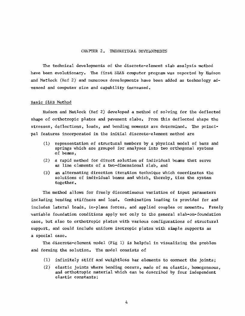
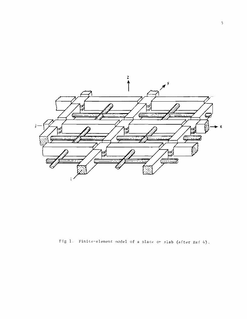
The discrete-element model (Fig 1) is helpful in visualizing the problem
and forming the solution. The model consists of
(1) infinitely stiff and weightless bar elements to connect the joints;
(2) elastic joints where bending occurs, made of an elastic, homogeneous, and orthotropic material which can be described by four independent elastic constants;
4
5
z
t
F 1. Finite-element model of a plate o¥ slab (after Ref 4).
(3) torsion bars which represent the torsional stiffness of the plate; and
(4) elastic support springs which provide foundation support.
All properties and loads can be freely variable from point to point.
Concentrated or distributed loads can be handled, including transverse loads,
in-plane forces, and external couples. Elastic restraints are provided by
vertical support springs.
The alternating-direction iteration method was originally used to solve
6
the equations describing the behavior of the model because it is well adapted
and easy to visualize. The model and method are too complex for hand cal
culations. For example cases having closed-form solutions, the discrete-element
solution with 8 to 10 increments produces results within 2 to 5 percent of the
closed-form solution in a few iterations. If the number of increments is in
creased to 16, the error comparison reduces to 1 to 3 percent (Ref 2).
A computer program, SLAB 17, which solves the equations implicitly for
the deflection patterns was developed in 1966. The program is written in
FORTRAN-63 for the CDC 1604 computer. Minor changes of input formats are re
quired to convert it for use on an IBM 7090. Compile time is 90 to 100 seconds
but binary decks compile in about 15 seconds. Automatic plot routines are
available for use with the program.
Direct Solution for Basic Slab Method
In the basic SLAB method (Ref 2) Hudson and Matlock presented a method
for the solution of discontinuous orthotropic plates and pavement slabs which
utilizes an alternating-direction iterative technique in the computer program.
In that method, efficient solutions depend on choosing the proper closure
parameters for input values; subsequent investigation has shown that this is
sometimes difficult to do, clearly defining a need for a one-pass method of
solving discontinuous orthotropic plates and pavement slabs.
A direct solution of the simultaneous equations formed by applying the
basic equation at all mesh points was developed by Stelzer and Hudson (Ref 3).
The method is not dependent on the selection of closure parameters as is the
iterative technique of Hudson and Matlock (Ref 2).
The method is verified by solving problems with available closed-form
answers. All problems solved in Ref 2 have been solved by the direct method
with consistent results (Ref 3). The method will solve problems which have
discontinuities not only in stiffness and support but also in loading and
boundary shape. The FORTRAN program is practical for use on computers with a
large core storage capacity such as the CDC 6600 Computer.
SLAB Method with Variable Increment Sizes
7
The basic SLAB method developed by Hudson and Matlock (Ref 2) and later
modified by Stelzer and Hudson (Ref 3) used equal lengths of increments in the
discrete-element model. The modeling accuracy of both methods of solution in
creased with the number of increments used in the model. It has been found
that the increased number of increments generally affected the solution only
near points of abrupt or rapid changes in load, support, or stiffness of the
plate and that complex loading patterns were difficult to represent in the
fixed length models. These findings clearly defined a need for a method which
would permit the use of variable increments in the discrete grid so that small
increments could be used near abrupt changes and larger increments in areas
where detailed accuracy is less important. Pearre and Hudson have described
a method to satisfy these requirements (Ref 4).
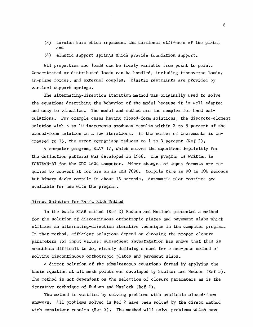
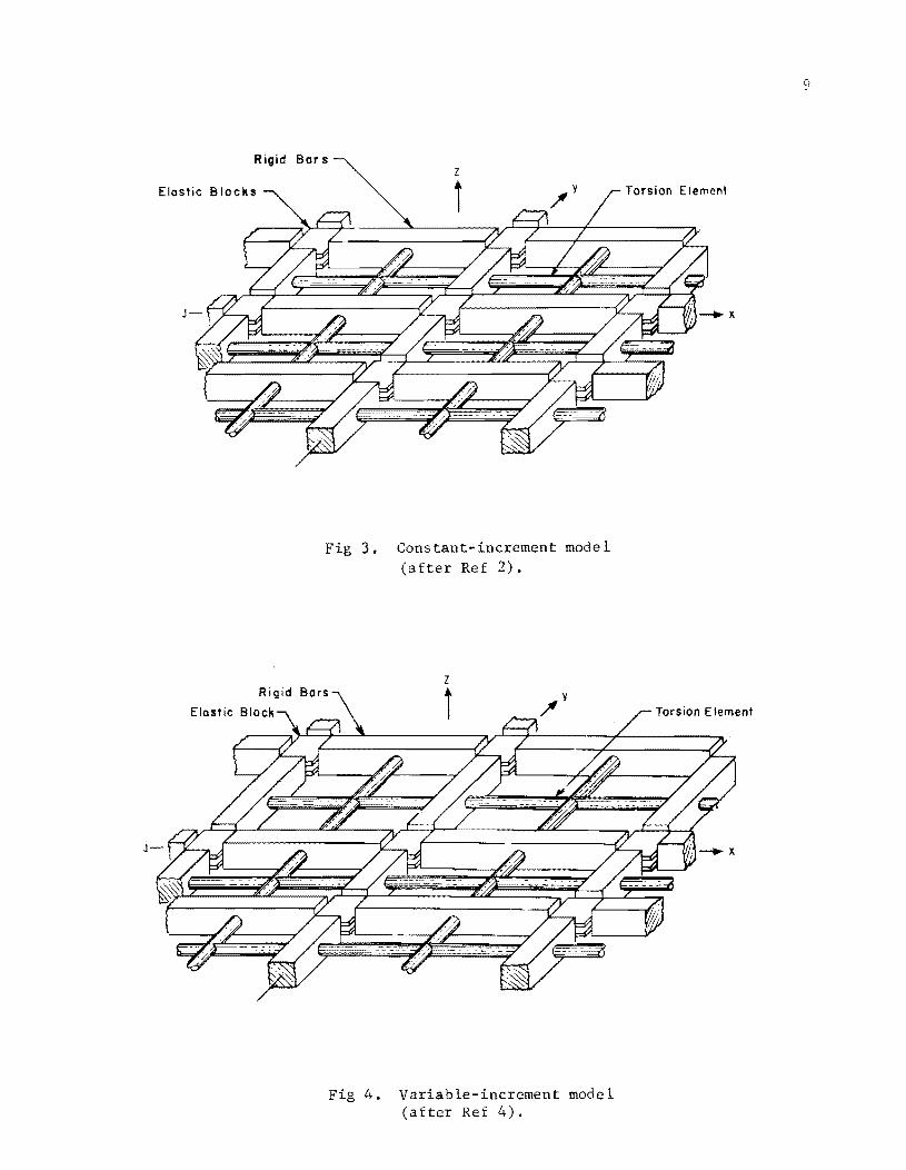
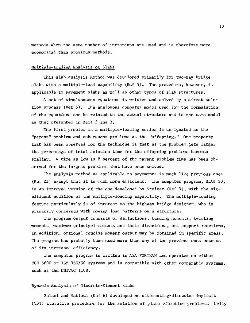
The primary difference in the capability of this computer program and
the previous two was the variable grid pattern, for which an example is shown
in Fig 2. Figures 3 and 4 show a comparison of the constant increment length
discrete-element model and the variable increment length discrete-element
model.
The FORTRAN computer program has been checked out and example problems
have been solved which illustrate that this model improves the accuracy of
the direct solution slab programs. The errors in deflection near loads can
be cut as much as 80 percent without increasing the solution time. The
vari~ble-increment-Iength solutions obtained are generally equivalent to
constant-increment-Iength solutions using two to three times as many increments
in each direction and thus represent a time saving of approximately 95 percent
over the previous methods (Ref 4).
The variable increment method has application to a broad variety of prob
lems since complex conditions can be met more exactly than with previous
methods. The method is more accurate for the distribution of uniform loads in
the near vicinity of supports because it can have a very small increment length
near the edge of the slab. Also, the method is more accurate than previous
8
y ,
F 2. Variable-increment grid pattern (after Ref 4).
Rigid
Elastic Torsion Element
Fig 3. Constant-increment model (after Ref 2).
Fig 4. Variable-increment model (after Ref 4).
9
methods when the same number of increments are used and is therefore more
economical than previous methods.
Multiple-Loading Analysis of Slabs
This slab analysis method was developed primarily for two-way bridge
slabs with a multiple-load capability (Ref 5). The procedure, however, is
applicable to pavement slabs as well as other types of slab structures.
10
A set of simultaneous equations is written and solved by a direct solu
tion process (Ref 5). The analogous computer model used for the formulation
of the equations can be related to the actual structure and is the same model
as that presented in Refs 2 and 3.
The first problem in a multiple-loading series is designated as the
"parent" problem and subsequent problems as the "offspring." One property
that has been observed for the technique is that as the problem gets larger
the percentage of total solution time for the offspring problems becomes
smaller. A time as low as 8 percent of the parent problem time has been ob
served for the largest problems that have been solved.
The analysis method as applicable to pavements is much like previous ones
(Ref 23) except that it is much more efficient. The computer program, SLAB 30,
is an improved version of the one developed by Stelzer (Ref 3), with the sig
nificant addition of the multiple-loading capability. The multiple-loading
feature particularly is of interest to the highway bridge designer, who is
primarily concerned with moving load patterns on a structure.
The program output consists of deflections, bending moments, twisting
moments, maximum principal moments and their directions, and support reactions.
In addition, optional concise moment output may be obtained in specific areas.
The program has probably been used more than any of the previous ones because
of its increased efficiency.
The computer program is written in ASA FORTRAN and operates on either
CDC 6600 or IBM 360/50 systems and is compatible with other comparable systems,
such as the UNIVAC 1108.
Dynamic Analysis of Discrete-Element Slabs
Salani and Matlock (Ref 6) developed an alternating-direction implicit
(ADI) iterative procedure for the solution of plate vibration problems. Kelly
11
and Matlock (Ref 7), on the other hand, utilized an efficient direct solution.
Nonlinear analysis is performed by adjusting the load rather than the stiff
ness coefficients. Since the stiffness matrix of the structure is not changed
during the solution procedure, the multiple load method of Panak and Matlock
(Ref 5) is applied for the iterative procedure.
The discrete-element plate model for static analysis is modified to in
clude the mass and damping properties of the system. Both mass and damping
are concentrated at the model joints or node points. Figure 5 shows a typical
joint from the model.
Equations of motion for the discrete-element model are developed by the
addition of the node point inertia and damping forces to the static equilibrium
equations. The resulting second-order simultaneous differential equations are
solved numerically by a step-by-step method of Wilson and Clough (Ref 27) based
on the assumption that the acceleration varies linearly between time stations.
The results of this assumption are a second-order variation of velocity and a
third-order variation of the deflection (Fig 6).
The stability of the linear acceleration algorithm is investigated and
recommendations are made for the selection of a stable time-step increment.
The time step required for stability is related to an estimate of the smallest
period of free vibration of the structure. It is shown that the time-step
increment for numerical analysis should be smaller than one-fourth of the mini
mum estimated period.
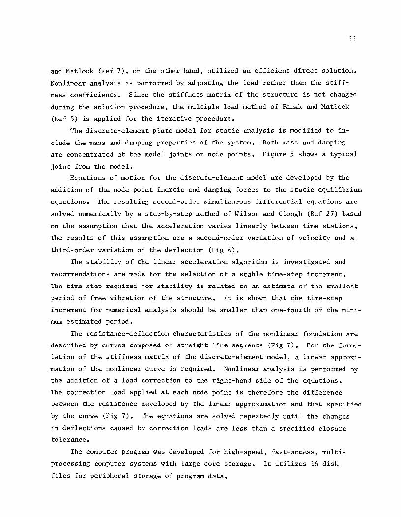
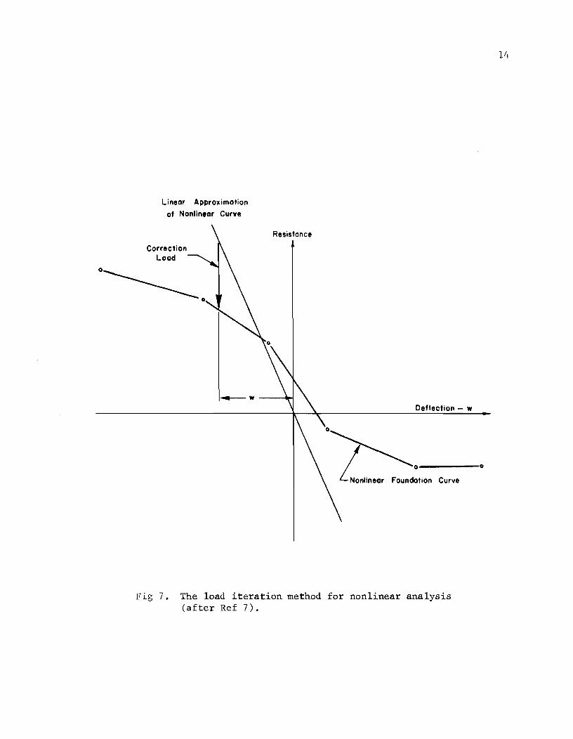
The resistance-deflection characteristics of the nonlinear foundation are
described by curves composed of straight line segments (Fig 7). For the formu
lation of the stiffness matrix of the discrete-element model, a linear approxi
mation of the nonlinear curve is required. Nonlinear analysis is performed by
the addition of a load correction to the right-hand side of the equations.
The correction load applied at each node point is therefore the difference
between the resistance developed by the linear approximation and that specified
by the curve (Fig 7). The equations are solved repeatedly until the changes
in deflections caused by correction loads are less than a specified closure
tolerance.
The computer program was developed for high-speed, fast-access, multi
processing computer systems with large core storage. It utilizes 16 disk
files for peripheral storage of program data.

Elastic Bending Element
Nonlinear Foundation Spring
Detail of Node Point
j--
Lumped Mass
Fixed Reference Frame
./ I
Fig 5. Joint detail of discrete-element model for dynamic analysis (after Ref 7).

.~ Ci
Time Station
k-3 k-2 k-I k
~o~ Linear Variation
Q
~ ~--~--------+---------~~---------+--~~----~-------------Qj u
:J.
,.. -
o~ A '00 •• 0-0,0., em'
u o ~--~--------+---~----~~---------+----------~-------------~
c: .2 '0
o
Third-Order Curve
~ ~--~--------+---------~-'r--------r----------+----------;;::
~
Fig 6. Node-point response for linear acceleration algorithm (after Wilson and Clough, Ref 27).
13
Linear Approximation
of Nonlinear Curve
Correction Load
0 _______
o
Resistance
~w ----II~
Deflection - w
Fig 7. The load iteration method for nonlinear analysis (after Ref 7).
14
o

To facilitate the program's extension or modification to include future
developments, subroutines are used extensively. The program consists of a
main driver and 27 subroutines, fourteen of which are for matrix and vector
operations.
15
The simultaneous equations which result from the linear acceleration
algorithm are solved by an efficient recursion-inversion, multiple load tech
nique for large systems of banded equations (Refs 5 and 9).
Although the dynamic load must be specified by the program user, the
simplified input form allows great flexibility, and either periodic or non
periodic loads, as well as stationary loads or loads moving with constant
velocity, can be input.
Analysis of Skew Slabs
The discrete-element method of analysis of anisotropic skew plates and
grids (Ref 10) was developed primarily for handling complex skew slab bridge
structures. The method, however, is flexible and can be applied to skewed
pavement slabs such as bridge approach slabs or jointed pavements with skewed
joints.
A mechanical model consisting of a tridirectiona1 system of rigid bars
and elastic joints is used to simulate anisotropic skew plates plus slab-and
grid systems in which the grid-beams may run in any three directions (Fig 8).
The model allows for the free linear elastic variation of stiffnesses and
support characteristics. Loads are applied at each joint to represent any
degree of concentrated or uniform loading.
By use of concepts of a continuum composed of interconnected fibers, stress
strain relationships for the anisotropic slab model are derived. Each grid
beam may thus be considered the same as a previously developed discrete-element
beam-column (Refs 11 and 12).
A computer program, SLAB 44, is written to apply the discrete-element
formulation of an anisotropic skew-plate and grid-beam system (Fig 8) in which
the grid-beams may run in any three directions.
The computer program SLAB 44 is written in FORTRAN for the CDC 6600 com
puter. The program is easily made compatible with IBM 360, UNIVAC 1108, and
other similar systems.
The input value of slab stiffness may be related either to orthogonal
directions or three specific directions. The program output consists of
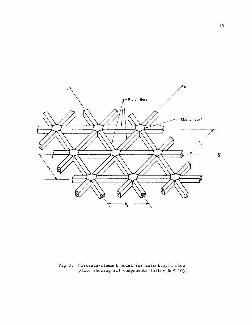
Rigid Bars
Fig 8. Discrete-element model for anisotropic skew plate showing all components (after Ref 10).
Joint
16
7

17
deflections, bending moments and twisting moments (or bending moments in three
directions), largest principal moments together with their directions, and
support reactions (or a statics check at each joint of the discrete-element
model).
CHAPTER 3. EXPERIMENTAL VERIFICATION
Introduction
The validity of any analytical method can best be proven by comparing its
solutions with actual test results. To obtain test results for use in verifying
discrete-element analytical methods for slabs-on-foundation, Agarwal and Hud
son (Ref 13) conducted a study of small-dimension plates and slabs with the
basic approach divided into two parts:
(1) a check of the modeling and method of solution for plates on simple supports for a variety of stiffness and load conditions, and
(2) an investigation of the modeling of the soil-structure interaction problem of a slab-on-foundation using linear and nonlinear characteristics according to the Winkler assumption.
Study of Plates
Tests for the first part of the study were conducted on both aluminum and
plexiglas plates, 25 inches square and resting on four-point supports. Pre
liminary tests involving four-edge support were conducted also, but because of
shortcomings in the test set-up they were not continued. The point supports
were placed 22 inches apart and a 25 by 25-inch plate waS set on them. Test
loading was done in increments of 10 pounds with a maximum of 40 pounds, plus
a seating load of 10 pounds. Deflections were measured by O.OOOl-inch dial
gages, and strains, where measured, were obtained using rosettes. The follow
ing four-point support tests were performed:
(1) deflections and strains on altmdmnn plate under center loading,
(2) deflections and strains on aluminum plate under off-center loading,
(3) deflections and strains on aluminum plate with a 6 by l/2-inch slot cut in the plate,
(4) deflections for isotropic plexiglas plate, and
(5) deflections for orthotropic (stiffness one one side) plexiglas plate.
Analytical solutions based on the discrete-element model were found using
the independently determined plate properties for each case.
18
A comparison of measured and computed deflections was made and the per
centage error calculated as a function of the maximum measured value.
19
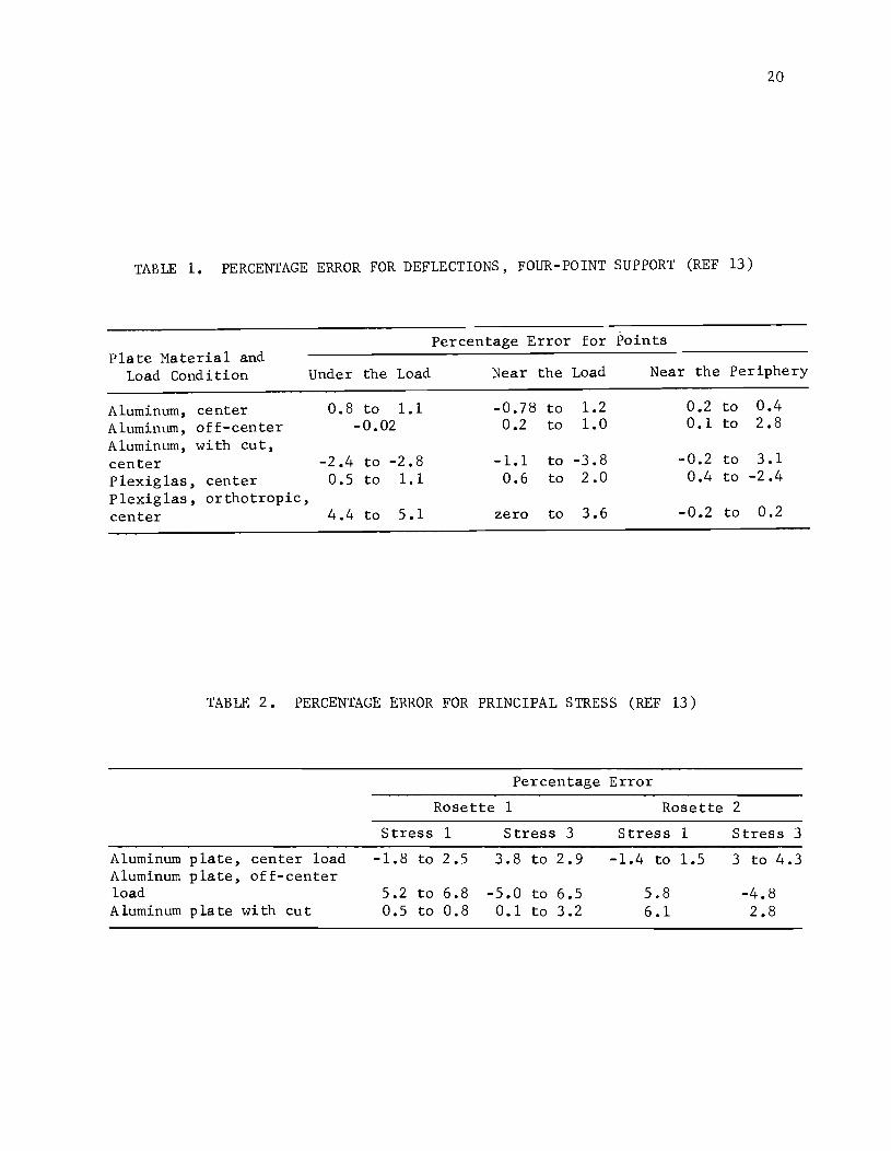
A summary of percentage error for deflections for all the tests is pre
sented in Table 1 for points "under the load," ''near the load," and "near the
periphery." The following observations can be made from this table.
For linearly elastic materials sllch as ahnnim.DIl, the analytical deflec
tions agreed with the experimental data within 4 percent for continuous plates
under center and off-center loadings and for plates with a discontinuity under
center loading. For an approximately linearly elastic material like plexiglas
the discrepancy for deflections was within about 2 percent for isotropic plates
and 5 percent for orthotropic plates.
From the strains of the rosettes, principal stresses were determined and
compared with the computed principal stresses. The percentage errors were
calculated using the individual strain values of the strain gages fixed at the
top and bottom of the plate, with the averages of these strain values thus
canceling any possible effects of in-plane forces. A summary of percentage
error for all tests is given in Table 2. It can be observed from this table
that for linearly elastic materials such as aluminum, the agreement between
computed and measured principal stresses for all three cases is within 6 per
cent.
Based on the above tests, the validity of the analytical solution for
plates of linearly elastic materials on rigid supports under a variety of load
and stiffness conditions is proven.
Slab-on-Foundation Study
After verifying the method of solution for linear materials on rigid
supports, tests for the second part of the study were conducted on a 9 by 9 by
l/8-inch aluminum slab resting on clay soil. The soil was prepared by extru
sion and placed in a supporting box at an average density of 116 lblcu ft and
a moisture content of 38 percent. Load was applied by a mechanical screw jack,
measured by a load cell, and recorded on a digital voltmeter. Deflections of
the slab were measured by linear variable differential transformers and dial
gages, and strains were measured by electrical resistance strain rosettes.
Tests were conducted for center. load and two-point corner loads. Load was ap
plied continuously up to 255 pounds for center load and 208 pounds for corner
20
TABLE 1. PERCENTAGE ERROR FOR DEFLECTIONS, FOUR-POINT SUPPORT (REF 13)
Percentage Error for Points Plate Material and
Load Condition Under the Load Near the Load Near the Periphery
Aluminum, center 0.8 to 1.1 -0.78 to 1.2 0.2 to 0.4 Aluminum, off-center -0.02 0.2 to 1.0 0.1 to 2.8
Aluminum, with cut, center -2.4 to -2.8 -1.1 to -3.8 -0.2 to 3.1 Plexiglas, center 0.5 to 1.1 0.6 to 2.0 0.4 to -2.4 Plexiglas, orthotropic, center 4.4 to 5.1 zero to 3.6 -0.2 to 0.2
TABLE 2. PERCENTAGE ERROR FOR PRINCIPAL STRESS (REF 13)
Percentage Error
Rosette 1 Rosette 2
Stress 1 Stress 3 Stress 1 Stress 3
Aluminum plate, center load -1.8 to 2.5 3.8 to 2.9 -1.4 to 1.5 3 to 4.3 Aluminum plate, off-center load 5.2 to 6.8 -5.0 to 6.5 5.8 -4.8 Aluminum plate with cut 0.5 to 0.8 0.1 to 3.2 6.1 2.8
21
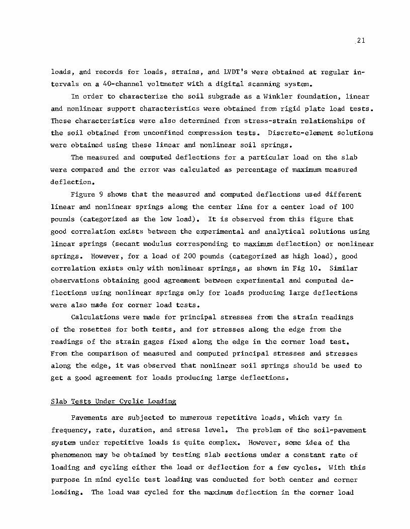
loads, and records for loads, strains, and LVDT's were obtained at regular in
tervals on a 40-channe1 voltmeter with a digital scanning system.
In order to characterize the soil subgrade as a Winkler foundation, linear
and nonlinear support characteristics were obtained from rigid plate load tests.
These characteristics were also determined from stress-strain relationships of
the soil obtained from unconfined compression tests. Discrete-element solutions
were obtained using these linear and nonlinear soil springs.
The measured and computed deflections for a particular load on the slab
were compared and the error was calculated as percentage of maximum measured
deflection.
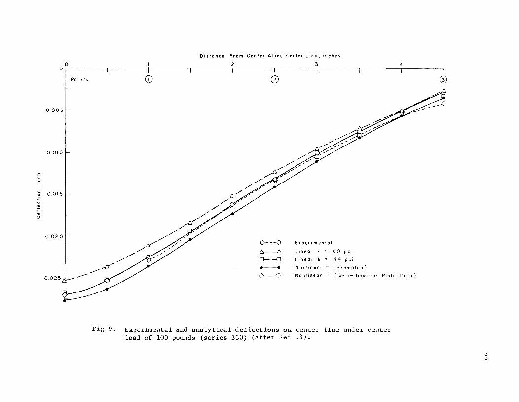
Figure 9 shows that the measured and computed deflections used different
linear and nonlinear springs along the center line for a center load of 100
pounds (categorized as the low load). It is observed from this figure that
good correlation exists between the experimental and analytical solutions using
linear springs (secant modulus corresponding to maximum deflection) or nonlinear
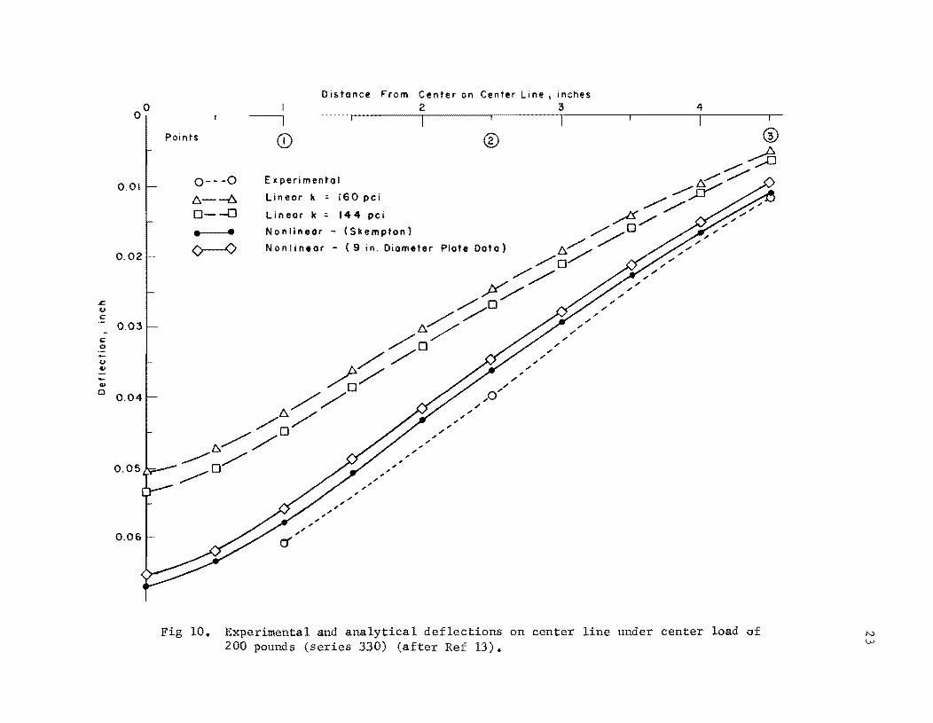
springs. However, for a load of 200 pounds (categorized as high load), good
correlation exists only with nonlinear springs, as shown in Fig 10. Similar
observations obtaining good agreement between experimental and computed de
flections using nonlinear springs only for loads producing large deflections
were also made for corner load tests.
Calculations were made for principal stresses from the strain readings
of the rosettes for both tests, and for stresses along the edge from the
readings of the strain gages fixed along the edge in the corner load test.
From the comparison of measured and computed principal stresses and stresses
along the edge, it was observed that nonlinear soil springs should be used to
get a good agreement for loads producing large deflections.
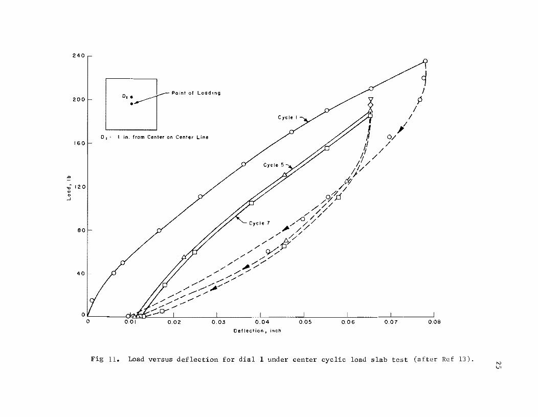
Slab Tests Under Cyclic Loading
Pavements are subjected to numerous repetitive loads, which vary in
frequency, rate, duration, and stress level. The problem of the soil-pavement
system under repetitive loads is quite complex. However, some idea of the
phenomenon may be obtained by testing slab sections under a constant rate of
loading and cycling either the load or deflection for a few cycles. With this
purpose in mind cyclic test loading was conducted for both center and corner
loading. The load was cycled for the maximum deflection in the corner load
.s:; u c
c 0 -U ell
ell 0
Distance From Center Along Center Line. inches
o 2 :3 4 o r----------.-----------r----------.-----------r----------.------~~_,_
Po i n ts
0.005
0.010
0.015
0.020
0.025
®
0---0
t:.- -/:::" 0--0
------<>----0
E~perimental
linear k 160 pc I
Linear k = 144 pci
Nonlinear - (Skempton)
Nonlinear - (9-1" Diameter Plate Data)
Fig 9. Experimental and analytical deflections on center line under center load of 100 pounds (series 330) (after Ref 13).
r. u c
c 0
U Q> -Q>
Cl
Distance From Center on Center Line I inches o 2 3 4
O~~~~.-~-----.~~----.--------.-------.--------.--------.--------,-~~--.--
0.01
0.02
0.03
0.04
0.05
0.06
Points
0---0
1:::,.--6. 0--0
• •
Experimental
Lineor k ; 160 pci
Linear k:: 144 pci
Nonlinear - (Skempton)
N on Ii near - (9 in. Diameter
, , .. ,. .. .. ,-.. .. , , ..
®
Plate Data)
, ,-
,-
'"
'" ,. '" 0" ,.
.. /'
,. , ,. ,. ,.
,. ,. ,. /' ,.
,. ,. ,. ;' ,.
;'
;' ,. ;'
,. ,. ,.
;'
Fig 10. Experimental and analytical deflections on center line under center load of 200 pounds (series 330) (after Ref 13).
24
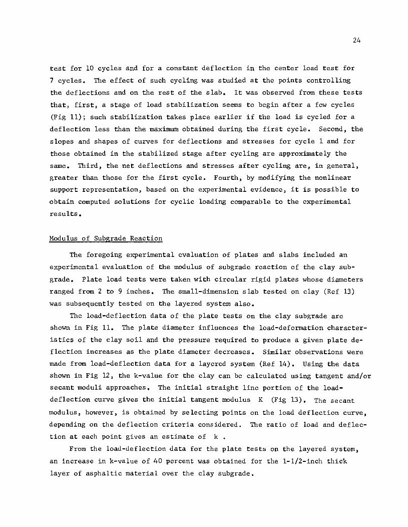
test for 10 cycles and for a constant deflection in the center load test for
7 cycles. The effect of such cycling was studied at the points controlling
the deflections and on the rest of the slab. It was observed from these tests
that, first, a stage of load stabilization seems to begin after a few cycles
(Fig 11); such stabilization takes place earlier if the load is cycled for a
deflection less than the maximum obtained during the first cycle. Second, the
slopes and shapes of curves for deflections and stresses for cycle 1 and for
those obtained in the stabilized stage after cycling are approximately the
same. Third, the net deflections and stresses after cycling are, in general,
greater than those for the first cycle. Fourth, by modifying the nonlinear
support representation, based on the experimental evidence, it is possible to
obtain computed solutions for cyclic loading comparable to the experimental
results.
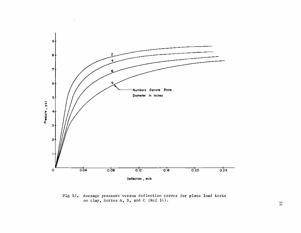
Modulus of Subgrade Reaction
The foregoing experimental evaluation of plates and slabs included an
experimental evaluation of the modulus of subgrade reaction of the clay sub
grade. Plate load tests were taken with circular rigid plates whose diameters
ranged from 2 to 9 inches. The small-dimension slab tested on clay (Ref 13)
was subsequently tested on the layered system also.
The load-deflection data of the plate tests on the clay subgrade are
shown in Fig 11. The plate diameter influences the load-deformation character
istics of the clay soil and the pressure required to produce a given plate de
flection increases as the plate diameter decreases. Similar observations were
made from load-deflection data for a layered system (Ref 14). Using the data
shown in Fig 12, the k-value for the clay can be calculated using tangent and/or
secant moduli approaches. The initial straight line portion of the load
deflection curve gives the initial tangent modulus K (Fig 13). The secant
modulus, however, is obtained by selecting points on the load deflection curve,
depending on the deflection criteria considered. The ratio of load and deflec
tion at each point gives an estimate of k •
From the load-deflection data for the plate tests on the layered system,
an increase in k-value of 40 percent was obtained for the 1-l/2-inch thick
layer of asphaltic material over the clay subgrade.
240
200
160
"0. 120 <> o
..J
80
40
o
0, •
• Point of Loading
0 1 : I in. from Center on Center Line
0.01 0.02 0.03
Cycle I
0.04 0.05 0.06 0.07 0.08
Deflection I inch
Fig 11. Load versus deflection for dial 1 under center cyclic load slab test (after Ref 13). N U1
9
8
7
6
5
1/1 ~
.. 4 ~
~ 1/1 .. CP ~
ll.
3
2
o
Numbers Denote Plate
Diameter in Inches
0.04 0.08 0.12 0.16 0.20 0.24
Deflection , inch
Fig 12. Average pressure versus deflection curves for plate load tests on clay, Series A, B, and C (Ref 14).

• ... :J
'" • l
k (Secont Modulus)
k (Tangent Modulus)
Deflection t VI
Fig 13. Tangent and secant moduli approaches for finding k-va1ue (after Ref 14).
27
CHAPTER 4. APPLICATION OF PROJECT METHODS
The SLAB analysis method has been applied to various civil engineering
problems in many ways. The two major applications of the SLAB method have
been to highway pavement design problems by the Highway Department and project
staff. Others have used the methods successfully for the analysis of airfield
pavements. These studies were not made on this project, but serve to illus
trate the broad applicability of the method. A few examples of these applica
tions which are most significant and which stand alone are summarized in the
following paragraphs.
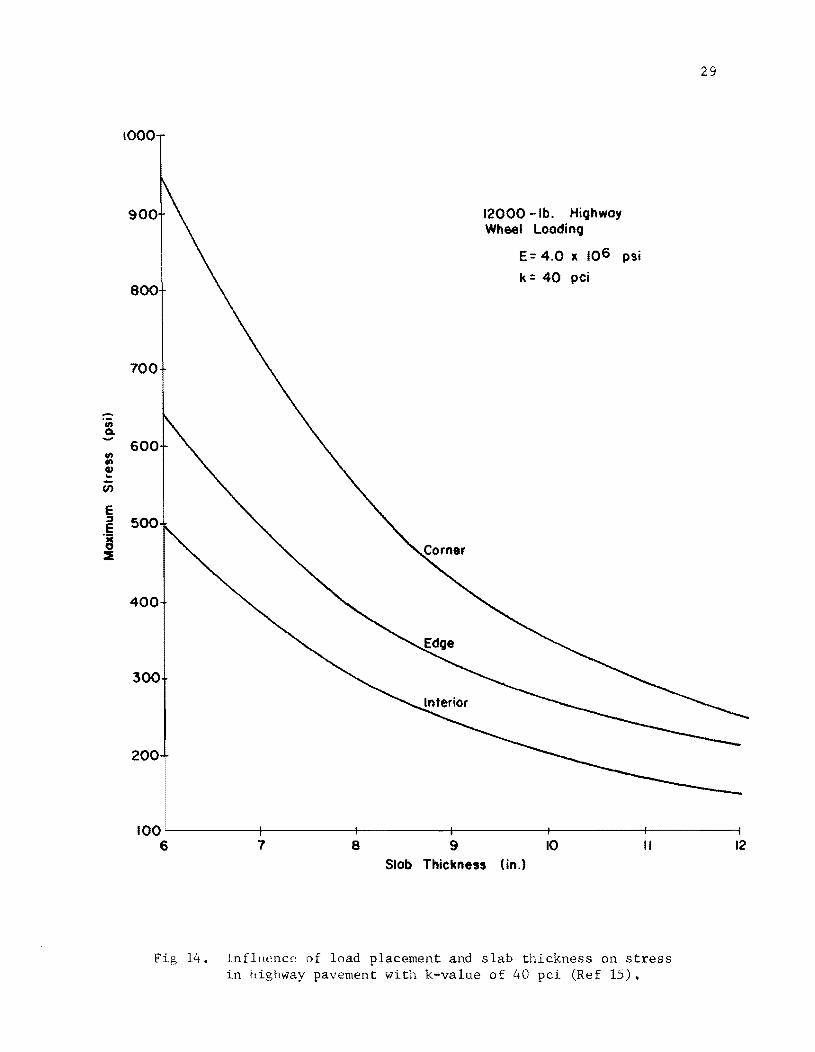
Load Placement Analysis
Historically, different types of rigid pavements have been characterized
by the load position selected for evaluating the design stress conditions. The
SLAB method, with its inherent capabilities, has been used by other persons to
conduct an extensive study on the effect of load placement on rigid pavement
behavior (Ref 15). These effects of load placement have been determined for
typical highway loading as well as airfield loadings. In this application, the
researchers have gone one step further than determining the stress or behavior
of the pavement with respect to load position and have related this to expected
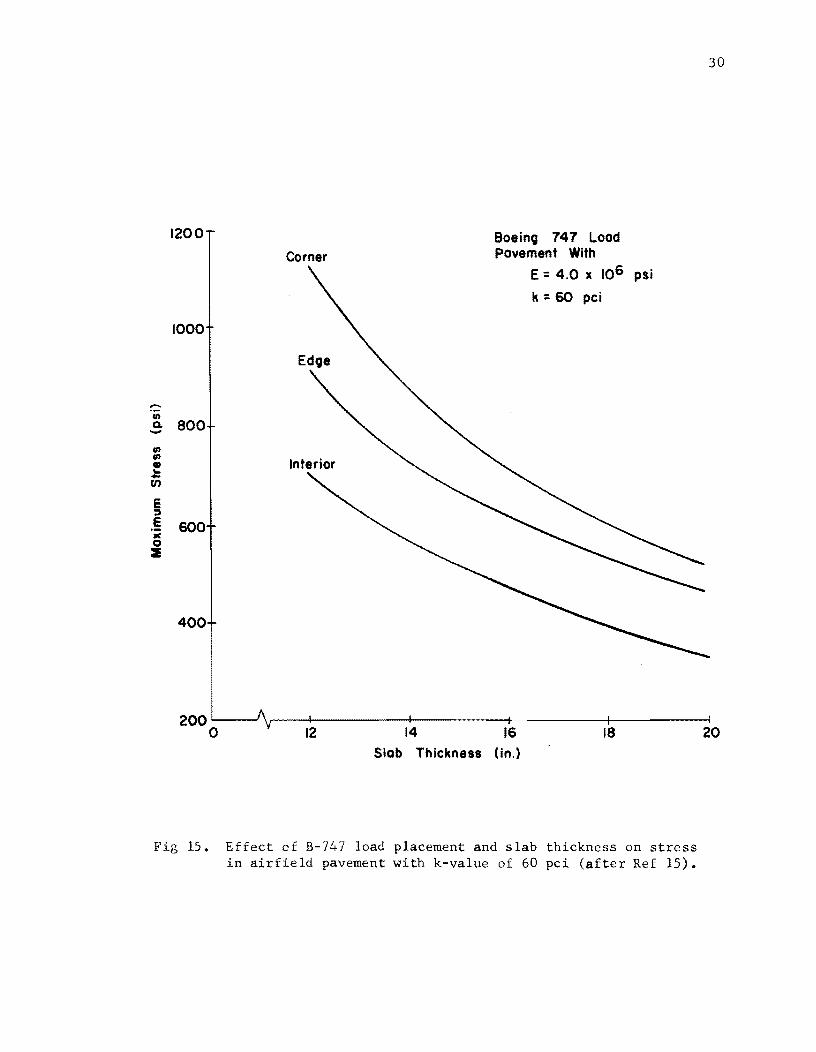
pavement life. Figures 14 and 15 show the relationship of pavement thickness,
load position, and stress conditions for a typical highway load and for a typi
cal jumbo jet aircraft loading respectively. For the design conditions which
are shown in Figs 14 and 15, these pavement stresses have been related to pave
ment life through the use of the pavement life relationships developed at the
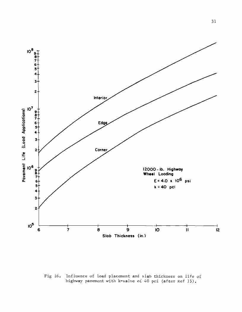
Road Test (Ref 26). In Figs 16 and 17 the relative performance effects of
load position can be estimated for the highway and the airfield loading con
ditions respectively.
This foregoing application of the SLAB method to the study of load posi
tions with respect to rigid pavement design analysis should be carried one
step further, that is, to evaluate the true effects of load transfer in these
pavements, because no single pavement consists of a single pavement slab. This
28
en Q.
en en G) .. -en
§ e 'j( 0 ~
1000
800
700
600
500
400
12000 -lb. Highway Wheel Loading
E:: 4.0 It 106 psi
k = 40 pci
29
100~------~r-------~--------~--------~--------~--------~
6 7 8 9 10 II 12 Slab Thickness (in.)
Fig 14. tnfluence of load placement and s lab thickness on stress in highway pavement with k-va1ue of 40 pci (Ref 15).
CIl Q,
CIl CIl QJ
'" -(f) E ~
.§ )( 0 2
1200
1000
800
600
400
200'----...J o
Corner
Interior
12 14
Boeing 747 Load Pavement With
16
E = 4.0 x 10⁶ psi
k = 60 pci
18 Slob Thickness (in.)
Fig 15. Effect of B- load placement and slab thickness on stress in airfield pavement with k-value of 60 pci (after Ref 15).
30
20
-." c 0
:;: 0 u Q. Q.
« "g 0 0 ..J -CP -..J -
108
101
9 8 1 6 ~
4
3
2
9 8 1 6 ~
4
3
2
~ 1069 ~ 8
> 1 0 Q. 6
~
4
3
2
10~ 6 7 8 9
12000 -lb. Hic;lh.oy Wheel Loodinc;l
E = 4.0 It 106 psi
k = 40 pci
10 II Slob Thickness (in.)
Fig 16. Influence of load placement and slab thickness on life of highway pavement with k-value of 40 pci (after Ref 15).
31
12

..-tI> C .2 ... ., .~ -a t "0 g ...J -CD -...J ... c CD e CD > ., 0..
105
9 8 7
104
103
6 S
4
3
2
9 8 7 6 S
4
3
2
9 8 7 6 S 4
3
2
o
32
Interior
Edge
Corner
Boeing 747 Load Pavement With
E = 4.0 x 10⁶ psi
k = 60 pci
12 14 16 18 20 Slab Thickness (in.)
Fig 17. Influence of B-747 load placement and slab thickness on life of airfield pavement with k-value of 60 pci (after Ref 15).
33
is no doubt an area of research where an existing analysis tool could be used.
There have been some significant applications of this method in design where
the design problem was solved with discrete-element SLAB methods used to
simulate load transfer and jointing conditions. Additional work is needed in
this important area.
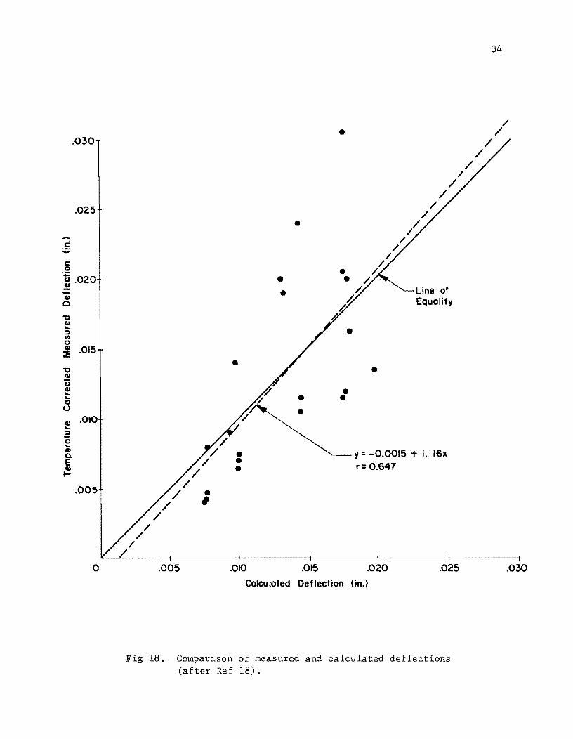
Analysis of Field Deflection Data
SLAB method has been used to analyze numerous continuously reinforced con
crete pavements in the State of Texas which were used in a performance study
by the Texas Highway Department (Refs 18 and 19). To analyze the effect of
various design variables on pavement behavior, the SLAB programs were used.
Pavement responses such as deflections and stresses were computed for a wide
variety of input variables. Figure 18 shows a comparison of the field de
flections and the computed deflections using the discrete-element slab com
puter program for analyzing these respective pavements (Ref 18). This appli
cation of the discrete-element SLAB analysis method was made prior to the de
tailed analysis of continuous reinforced concrete pavements using the discrete
element method, which is discussed in the next paragraph.
Theoretical Analysis of CRCP
The bending rigidity of structural members is affected significantly by
discontinuities and such is the case in continuously reinforced concrete pave
ment which contains a series of tiny volume change cracks. These discontinuities
have been analyzed theoretically by Abou-Ayyash and Hudson by application of
the discrete-element method of slab analysis (Ref 19). It has been shown that
the bending stiffness at cracked locations in continuously reinforced concrete
pavement is reduced between 80 and 90 percent from the uncracked stiffness
value. This is illustrated in Fig 19, which relates the longitudinal reinforce
ment percentage to the percentage reduction in bending stiffness for several
different concrete strengths.
After theoretically characterizing the volume change cracks in continuously
reinforced pavement, a sensitivity analysis of continuously reinforced pavement
was made using the SLAB analysis method. For the range in the variables studied,
it was found that slab bending stiffness and subgrade modulus explained most
of the variations in deflections and principal moments. Crack spacing showed
minor influence on slab behavior.
.-. c -c o
.030
.025
~ .020 -• o "0 IU .. :J en a :I .015
"0 IU U • ... ... o U
• .010 ... :J -a ... • 0. E ~
.005
o
/ /
/
/ /
/ /
/
"/ /
/
• ,
•
• • •
• •
•
• •
IJ
•
· / . /.. /.
h o
•
• • •
/
/ /
/
/ /
/
/ /
/
Line of Equality
y = -0.0015 + 1.116x r= 0.647
/
.005 .010 .015 .020 .025
Calculated Deflection (in.)
Fig 18. Comparison of measured and calculated deflections (after Ref 18).
34
/ /
/
/ /
.030

94
92
90 If) If) Q) c -' ..... 88 -(j) 01 C "0 86 c Q)
CD c
84 c 0 -u ::::) 82 "0 Q)
a:: Q)
g 80 -c Q) u ~
78 Q)
0...
76
74
Note: Plot is based on an allowable concrete compressive stress
of 0.45 f~ and allowable tensile steel stress of 0.75 f y.
% reduction in bending Stiffness = (1- lG) 100
~ = gross moment of inertia
bt3 =12
r = Average moment of inertia (Eq. 3.13)
0.2 0.3 0.4 0.5 0.6 0.7 0.8 0.9 1.0 1.1
Longitudinal Percentage Reinforcement, P = ~; x 100
Fig 19. Variation of the percentage reduction in bending stiffness at crack location with longitudinal percentage reinforcement (after Ref 19).
35
36
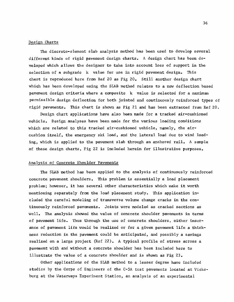
Design Charts
The discrete-element slab analysis method has been used to develop several
different kinds of rigid pavement design charts. A design chart has been de
veloped which allows the designer to take into account loss of support in the
selection of a subgrade k value for use in rigid pavement design. This
chart is reproduced here from Ref 20 as Fig 20. Still another design chart
which has been developed using the SLAB method relates to a new deflection based
pavement design criteria where a composite k value is selected for a maximum
permissible design deflection for both jointed and continuously reinforced types of
rigid pavements. This chart is shown as Fig 21 and has been extracted from Ref 20.
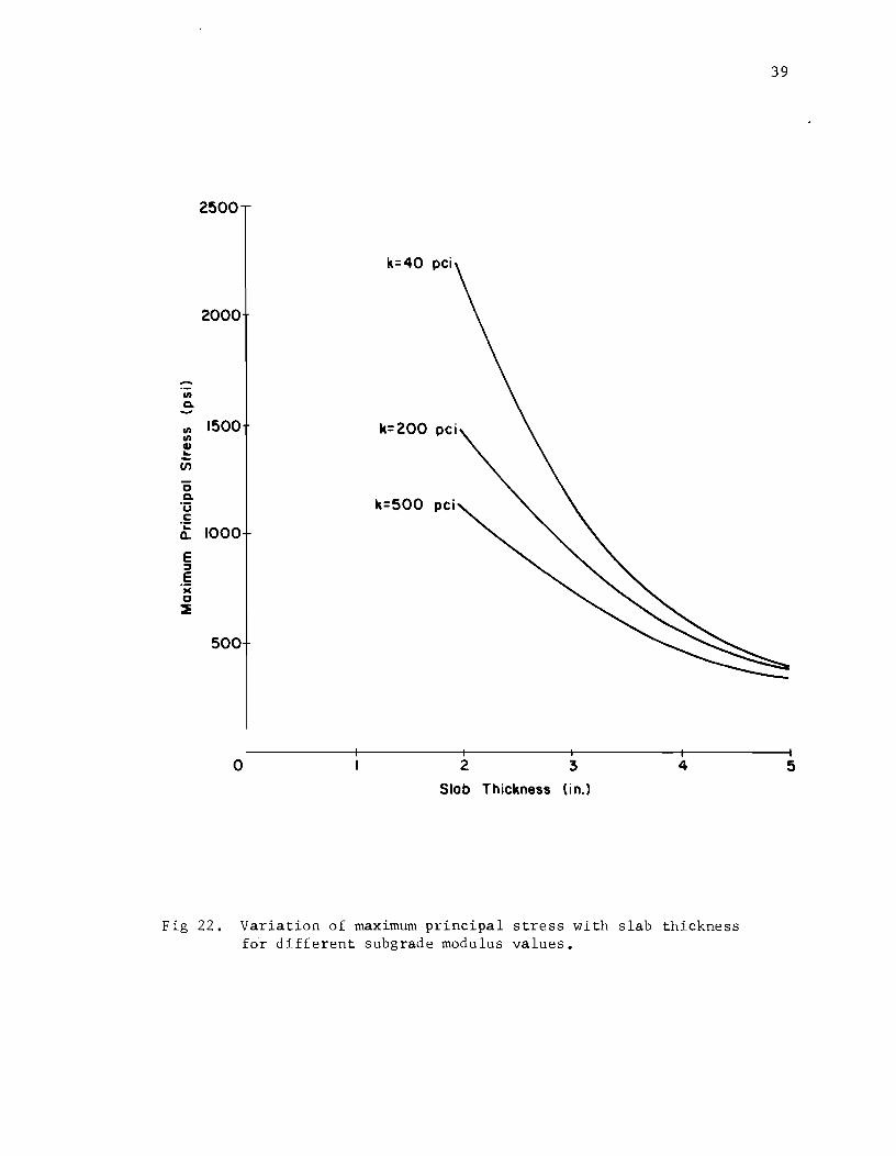
Design chart applications have also been made for a tracked air-cushioned
vehicle. Design analyses have been made for the various loading conditions
which are related to this tracked air-cushioned vehicle, namely, the air
cushion itself, the emergency ski load, and the lateral load due to wind load
ing, which is applied to the pavement slab through an anchored rail. A sample
of these design charts, Fig 22 is included herein for illustrative purposes.
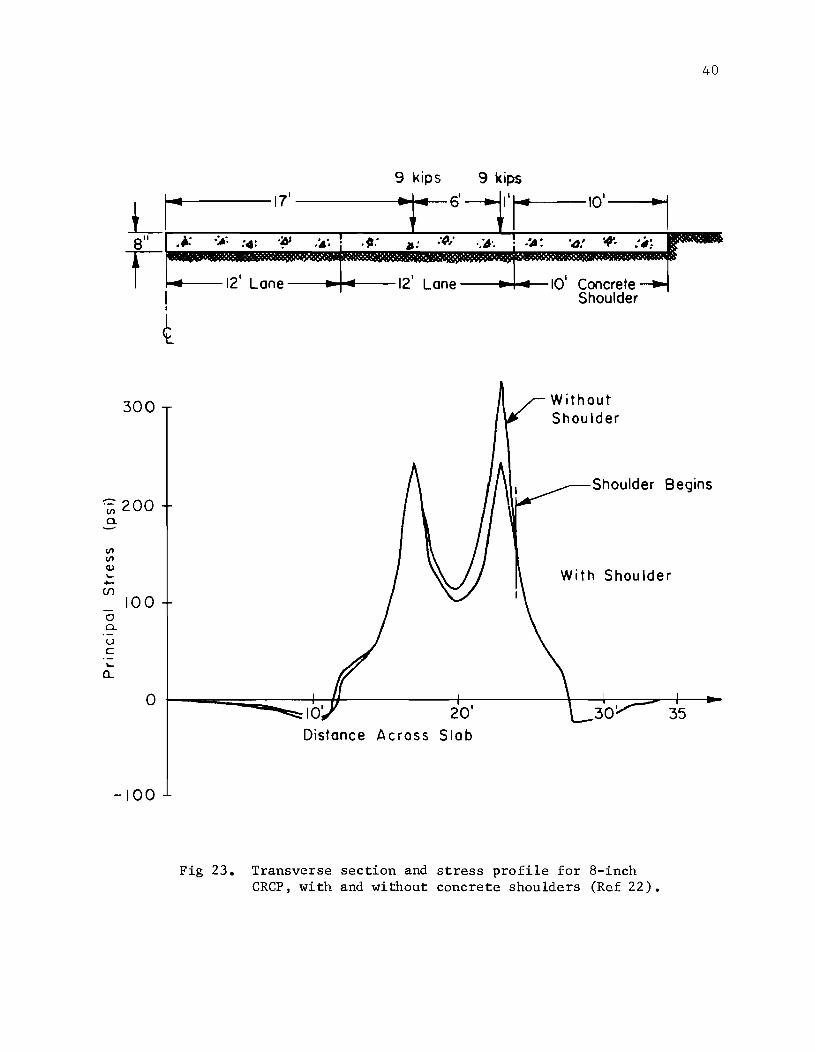
Analysis of Concrete Shoulder Pavements
The SLAB method has been applied to the analysis of continuously reinforced
concrete pavement shoulders. This problem is essentially a load placement
problem; however, it has several other characteristics which make it worth
mentioning separately from the load placement study. This application in
cluded the careful modeling of transverse volume change cracks in the con
tinuously reinforced pavements. Joints were modeled as cracked sections as
well. The analysis showed the value of concrete shoulder pavements in terms
of pavement life. Thus through the use of concrete shoulders, either insur
ance of pavement life would be realized or for a given pavement life a thick
ness reduction in the pavement could be anticipated, and possibly a savings
realized on a large project (Ref 22). A typical profile of stress across a
pavement with and without a concrete shoulder has been included here to
illustrate the value of a concrete shoulder and is shown as Fig 23.
Other applications of the SLAB method to a lesser degree have included
studies by the Corps of Engineers of the C-SA test pavements located at Vicks
burg at the Waterways Experiment Station, an analysis of an experimental

500
100
50
.... ... c: .~ WI .. 0
"0 ... 10
5
5 10 50 km (Assumed k)
E. F. = Erodability Factor
100 500
Fig 20. Correction of k-value for effect of erosive nature of subbase (after Ref 20).
1000

u Q.
CII ~
0 >
I ~
c 0' .c;; CII 0
1000
800
600
400
200
100
80
60
40
20
o 0.01 0.02 0.03 0.04 Deflection (in.)
Fig 21. Variation of maximum permissable design deflection with composite subgrade support and pavement thickness (after Ref 20).
38
0.05
2500
k=40 pci
2000
m 0-
m 1500 k=200 m GI ... -en 0 0-
k=500 'u c: '~
1000 Q..
E :::I E 'w 0 ~
500
o 2 3 4
Slob Thickness (in.)
Fig 22. Variation of maximum principal stress with slab thickness for different subgrade modulus values.
39
5
L a"
t
300
:-=:- 200 III a.
III III Q) '-+-(f)
100 0 a. u c ~
a..
0
-100
40
9 kips 9 kips
I~ 17' .. 6'--., I'i 10'1
.~ .~~ :,.: '~I .~', ;i!: lJ: :~.; '.if', ! .~: '",. * :~: 5" ~
12' Lone 12' Lone ~ - 10' Concrete ---.. I Shoulder ,
Shoulder
Shoulder Begins
With Shoulder
10' 20' Distance Across Slab
Fig 23. Transverse section and stress profile for 8-inch CRCP, with and without concrete shoulders (Ref 22).
pavement studies, and an analysis of experimental studies which have been
used to verify the SIAB method itself (Ref 13).
Other Proposed Applications
41
There are many technical problems which the SLAB method could be applied
to with worthwhile effort. The SLAB method could be used to analyze proposed
overloads for which permits are requested for carrying these loads over state
highway pavements and bridges. This analysis would not only give insight into
what stress might occur, but also what deflection patterns would be encountered.
A second application might be to special unique design problems such as a
hydraulic inlet in CRCP which is in essence somewhat of an anchor in the con
tinuously reinforced pavement and can cause cracking distress. Other design
applications include skewed bridge approach slabs, ramp connections of free
ways, and bridge approaches which are partially structurally supported and
partially supported by foundations.
The third proposed application is in the rigid pavement design system being
developed at The University of Texas (Ref 23). This proposed application has
a wide variety of inputs that can improve the existing structural models as
well as allow the addition of other necessary ones. Some of these applications
would be as follows:
(1) Load transfer across rigid pavement joints is an important problem that has not received enough past attention. The SLAB method offers a unique tool to analyze the problem. Appropriate reductions in bending and twisting stiffnesses can be applied at the joints to simulate an existing load transfer condition.
(2) The effect of nonlinear material properties and nonlinear subgrade support on slab behavior can be investigated. This analysis offers a better characterization of actual condi~ions.
(3) Crack width in continuously reinforced concrete has a significant influence on slab response and hence pavement performance. To simulate this effect, different nonlinear moment curvature relationships for different crack widths can be used. Correlating the resulting deflections and/or stresses with field observations, a crack width design criterion can be estab1ished e
(4) Variations in deflections and stresses due to various tire pressures and corresponding areas of contact can be studied by using the SLAB methode This is highly significant since the rate of change of these responses is very high in the vicinity of the loaded area.

42
(5) Another proposed application is the study of the influence of skew joints on pavement behavior. Only a slight amount of work has been done in this area.

CHAPTER 5. IMPLEMENTATION
Implementation of technical developments in this research project has been
somewhat slower than desired as a result of the complexities involved. Com
puter programs which replace hand computation methods of analysis are not
readily implementable in a large-production organization without direct access
to computer facilities and trained personnel. The computer programs for slab
analysis which have been developed on this research project have been written
in what is termed ASA standard FORTRAN so that the programs will be compatible
with computers other than those for which they were developed with a minimum
of FORTRAN conversion. The programs have been developed for several different
computers during the past five years. The first working SLAB program, SLAB 17
(Ref 2), Was developed on The University of Texas CDC 1604 computer. At that
time the Texas Highway Department operated a similar computer, the CDC l604A.
This program was implemented on the Highway Department computer with reasonable
ease.
As time and technology progressed, The University of Texas acquired the
CDC 6600 computer facility. With this computing facility, SLAB programs be
came larger and more complex. The next SLAB program developed which was im
plemented on the Texas Highway Department computer facility was SLAB 30 (Ref 5).
By this time, the Highway Department no longer used the l604A, but had obtained
an IBM system 360 computer facility. The SLAB 30 computer program was imple
mented on that computer and has been used for some time.
The most recent computer development which has been implemented on the
Highway Department IBM 360 computer is SLAB 49. This computer program is very
similar to SLAB 30, but has in it many economizing features with regard to
computer time as well as other general output capabilities or user oriented
capabilities (Ref 24). This program, SLAB 49, represents the most up-to-date
discrete-element method of SLAB analysis. The program has such features as
printer plots, microfilm plots, perspective view plots, and print-out of only
a selected portion of the complete set of computed output.
43
44
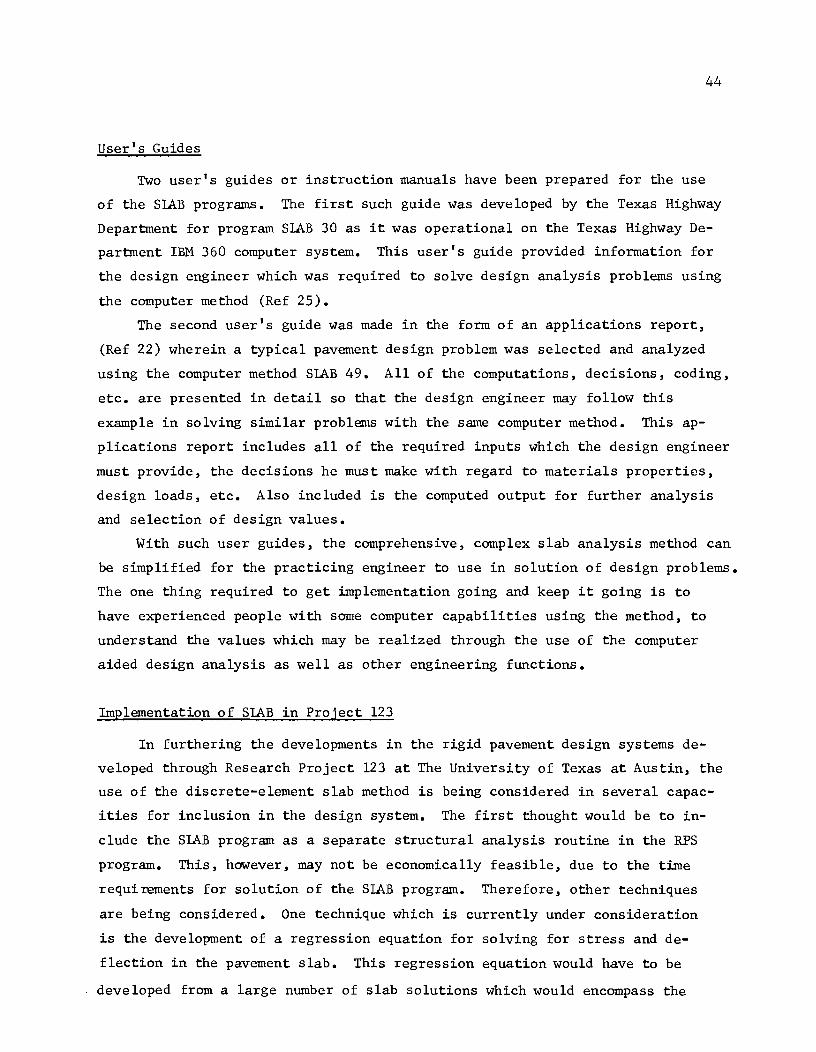
User's Guides
Two user's guides or instruction manuals have been prepared for the use
of the SLAB programs. The first such guide was developed by the Texas Highway
Department for program SLAB 30 as it was operational on the Texas Highway De
partment IBM 360 computer system. This user's guide provided information for
the design engineer which was required to solve design analysis problems using
the computer method (Ref 25).
The second user's guide was made in the form of an applications report,
(Ref 22) wherein a typical pavement design problem was selected and analyzed
using the computer method SLAB 49. All of the computations, decisions, coding,
etc. are presented in detail so that the design engineer may follow this
example in solving similar problems with the same computer method. This ap
plications report includes all of the required inputs which the design engineer
must provide, the decisions he must make with regard to materials properties,
design loads, etc. Also included is the computed output for further analysis
and selection of design values.
With such user guides, the comprehensive, complex slab analysis method can
be simplified for the practicing engineer to use in solution of design problems.
The one thing required to get implementation going and keep it going is to
have experienced people with some computer capabilities using the method, to
understand the values which may be realized through the use of the computer
aided design analysis as well as other engineering functions.
Implementation of SLAB in Project 123
In furthering the developments in the rigid pavement design systems de
veloped through Research Project 123 at The University of Texas at Austin, the
use of the discrete-element slab method is being considered in several capac
ities for inclusion in the design system. The first thought would be to in
clude the SLAB program as a separate structural analysis routine in the RPS
program. This, however, may not be economically feasible, due to the time
requirements for solution of the SLAB program. Therefore, other techniques
are being considered. One technique which is currently under consideration
is the development of a regression equation for solving for stress and de
flection in the pavement slab. This regression equation would have to be
developed from a large number of slab solutions which would encompass the
45
entire range of load configurations, load ranges, pavement material property
ranges, and pavement types. In general, it would be a very comprehensive
sensitivity analysis of the SLAB program and would be a costly undertaking
from the standpoint of computer time and manpower required. Some development
work in this area has been done (Ref 19) for continuously reinforced concrete
pavements for a single loading condition where some of the paving materials
parameters were studied over reasonable ranges. Other attempts are also being
made to include the SLAB method in the rigid pavement design system.
CHAPTER 6. SUMMARY
Twenty-seven reports on this research project have been prepared and for
warded to the sponsor. Of these ten are directly applicable to SLAB and pave
ment analysis and design. These reports document the technical developments
and verifications of these analytical techniques and illustrate how the method
can be applied to the engineering design of rigid pavements. This report has
summarized some of the important developments on this research project which
are pertinent to pavement slab analysis and design.
The analytical method has been developed, verified, and refined as well
as implemented to some degree. Continued use in engineering practice and in
educational functions will help to acquaint more engineers with the method and
help to make it a routine capability in pavement design offices.
The following is a list of brief recommendations which are offered at
the conclusion of this project:
(1) The SLAB method should continue to be used for special problem analysis by the Texas Highway Department.
(2) The analytical capability should be incorporated in the rigid pavement design system as early as possible.
(3) The method should be extended to be more generally applicable to composite rigid pavements and to efficiently handle nonlinear materials properties as well as nonlinear subgrade support values.
46
REFERENCES
1. Love, A. E. H., A Treatise on the Mathematical Theory of Elasticity, Fourth Edition, Dover Publications, New York, 1944.
2G Hudson, W. Ronald, and Hudson Matlock, '~iscontinuous Orthotropic Plates and Slabs," Research Report No. 56-6, Center for Highway Research, The University of Texas at Austin, May 1966.
3. Stelzer, C. Fred, Jr., and W. Ronald Hudson, I~ Direct Computer Solution for Plates and Pavement Slabs," (DSlAB 5), Research Report No. 56-9, Center for Highway Research, The University of Texas at Austin, October 1967.
4. Pearre, Charles M., III, and W. Ronald Hudson, "A Discrete-Element Solution of Plates and Pavement Slabs Using a Variable-Increment-Length Model," Research Report No. 56-11, Center for Highway Research, The University of Texas at Austin, April 1969.
5. Panak, John J., and Hudson Matlock, I~ Discrete-Element Method of Multiple-Loading Analysis for Two-Way Bridge Floor Slabs," Research Report No. 56-13, Center for Highway Research, The University of Texas at Austin, January 1970.
6. Salani, Harold J., and Hudson Matlock, I~ Finite-Element Method for Vibrating Beams and Plates," Research Report No. 56-8, Center for Highway Research, The University of Texas at Austin, June 1967.
7. Kelley, Allen E., and Hudson Matlock, '~ynamic Analysis of DiscreteElement Plates on Nonlinear Foundations," Research Report No. 56-17, Center for Highway Research, The University of Texas at Austin, January 1970.
8. Wilson, Edward L., and Ray W. Clough, '~ynamic Response by Step-by-Step Matrix Analysis," Sympositml on the Use of Computers in Civil Engineering, Lisbon, Portugal, October 1962.
9. Endres, Frank L., and Hudson Matlock, I~n Algebraic Equation Solution Process Formulated in Anticipation of Banded Linear Equations, II Research Report No. 56-19, Center for Highway Research, The University of Texas at Austin, January 1971.
10. Vora, Mahendraktmlar R., and Hudson Matlock, I~ Discrete-Element Analysis for Anisotropic Skew Plates and Grids," Research Report No. 56-18, Center for Highway Research, The University of Texas at Austin, August 1970.
47
48
11. Matlock, Hudson, and T. A. Haliburton, I~ Finite-Element Method of Solution for Linearly Elastic Beam-Columns," Research Report No. 56-1, Center for Highway Research, The University of Texas at Austin, September 1966.
12. Matlock, Hudson, and T. P. Taylor, I~ Computer Program to Analyze BeamColumns Under Movable Loads," Research Report No. 56-4, Center for Highway Research, The University of Texas at Austin, June 1968.
13. Agarwal, Sohan L., and W. Ronald Hudson, '~xperimental Verification of Discrete-Element Solutions for Plates and Pavement Slabs," Research Report No. 56-15, Center for Highway Research, The University of Texas at Austin, April 1970.
14. Siddiqi, Qaiser S., and W. Ronald Hudson, '~xperimental Evaluation of Subgrade Modulus and Its Application in Model Slab Studies," Research Report No. 56-16, Center for Highway Research, The University of Texas at Austin, January 1970.
15. Treybig, Harvey J., W. Ronald Hudson, and B. F. McCullough, '~ffect of Load Placement on Rigid Pavement Behavior," Paper No. 8543, Transportation Engineering Journal, Proceedings of ASCE, November 1971.
16. McCullough, B. F., and Harvey J. Treybig, I~ Statewide Deflection Study of Continuously Reinforced Concrete Pavement in Texas ,II Highway Research Record No. 239, 1968, pp 150-174.
17. Treybig, Harvey, IIPerformance of Continuously Reinforced Concrete Pavement in Texas," Highway Research Record No. 291, 1969, pp 32-47.
18. Treybig, Harvey J., 'Ubservation and Analysis of Continuously Reinforced Concrete Pavement,1I Research Report No. 46-7, Texas Highway Department, April 1968.
19. Abou-Ayyash, Adnan, and W. Ronald Hudson, '~na1ysis of Bending Stiffness Variation at Cracks in Continuous Pavements," Research Report No. 56-22, Center for Highway Research, The University of Texas at Austin, August 1971.
20. McCullough, B. F., and W. R. Hudson, IISubbase Design Manual for Portland Cement Concrete Pavements," A Report submitted to United States Steel Corporation, Pittsburgh, Pennsylvania, Materials Research and Development Corporation, November 1970.
21. Treybig, Harvey J., and B. F. McCullough, I~ Recommended Procedure for the Design of Rigid Pavements,1I Research Report No. 502-lF, Center for Highway Research, The University of Texas at Austin, December 1971.
22. Treybig, Harvey J., W. Ronald Hudson, and Adnan Abou-Ayyash, '~pplication of Slab Analysis Methods to Rigid Pavement Problems,1I Research Report No. 56-26, Center for Highway Research~ The University of Texas at Austin, May 1972.
23. Kher, Ramesh K., W. Ronald Hudson, and B. Frank McCullough, '~ Systems Analysis of Rigid Pavement Design," Research Report No. 123-5, published jointly by Texas Highway Department; Center for Highway Research, The University of Texas at Austin; Texas Transportation Institute, Texas A&M University, November 1970.
49
240 Panak, John J., and Hudson Matlock, '~ Discrete-Element Method of Analysis for Orthogonal Slab and Grid Bridge Floor Systems," Research Report No. 56-25, Center for Highway Research, The University of Texas at Austin, August 1971.
25. ''Users Manual-Computer Program SlAB 30," Texas Highway Department, Bridge Division, January 1970.
26. Langsner, George, T. S. Huff, and Wallace J. Liddle, ''Use of Road Test Findings by AASHO Design Committee," Special Report 73, Highway Research Board, 1962.
27. Wilson, Edward L., and Ray W. Clough, '~ynamic Response by Step-by-Step Matrix Analysis," SymposiLnn on the Use of Computers in Civil Engineering, Lisbon, Portugal, October 1962.
THE AUTHORS
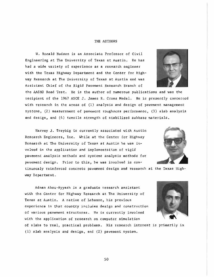
W. Ronald Hudson is an Associate Professor of Civil
Engineering at The University of Texas at Austin. He has
had a wide variety of experience as a research engineer
with the Texas Highway Department and the Center for High
way Research at The University of Texas at Austin and was
Assistant Chief of the Rigid Pavement Research Branch of
the AASHO Road Test. He is the author of numerous publications and was the
recipient of the 1967 ASCE J. James R. Croes Medal. He is presently concerned
with research in the areas of (1) anaLysis and design of pavement management
systems, (2) measurement of pavement roughness performance, (3) slab analysis
and deSign. and (4) tensile strength of stabilized subbase materials.
Harvey J. Treybig is currently associated with Austin
Research Engineers, Inc. While at the Center for Highway
Research at The University of Texas at Austin he was in
volved in the application and implementation of rigid
pavement analysis methods and systems analysis methods for
pavement design. Prior to this, he waS involved in con
tinuously reinforced concrete pavement design and research at the Texas High
way Department.
Adnan Abou-Ayyash is a graduate research assistant
with the Center for Highway Research at The Universicy of
Texas at Austin. A native of Lebanon, his previous
experience in that country includes design and construction
of various pavement structures. He is currently involved
with the application of research on computer simulation
of slabs to real. practical problems. His research interest is primarily in
(1) slab analysis and design, and (2) pavement system.
50
Recommended