A320 Series
Gravity Referenced, Ultra-Low Range Linear Servo Accelerometer
In North America: Email: [email protected] Rest of World: Email: [email protected] Website: www.sherbornesensors.com
Sherborne Sensors, a Nova Metrix company A320 - 2013 ISS 1
A32 0 1 - G DESIGNATION & ORDERING CODE
Series Number
3 Electrical Connector5 Solder Pins
0 Standard Unit
0 Standard Unit 1 Customer Special
RANGE ±g
Features • Ultra Low Range ±1/10 g to ± 2g
• High-level output signal
• Fully self-contained - connect to a DC power source and a readout or control device for a complete operating system
• Extremely rugged, withstands 1500g shock
Applications • Geophysical, seismic and civil engineering
studies
• Flight test monitoring
• Structural monitoring
• Low acceleration analysis
Description The A320 Series are high precision, closed loop, servo balance, ultra-low range accelerometers that can be used for a wide variety of industrial and aerospace applications. Despite its very low measuring range, the A320 Series are extremely robust and shock resistant. Electrical terminations are via 6-pin, bayonet lock connector or solder pins.
A320 Series
Gravity Referenced, Ultra-Low Range Linear Servo Accelerometer
In North America: Email: [email protected] Rest of World: Email: [email protected] Website: www.sherbornesensors.com
Sherborne Sensors, a Nova Metrix company A320 - 2013 ISS 1
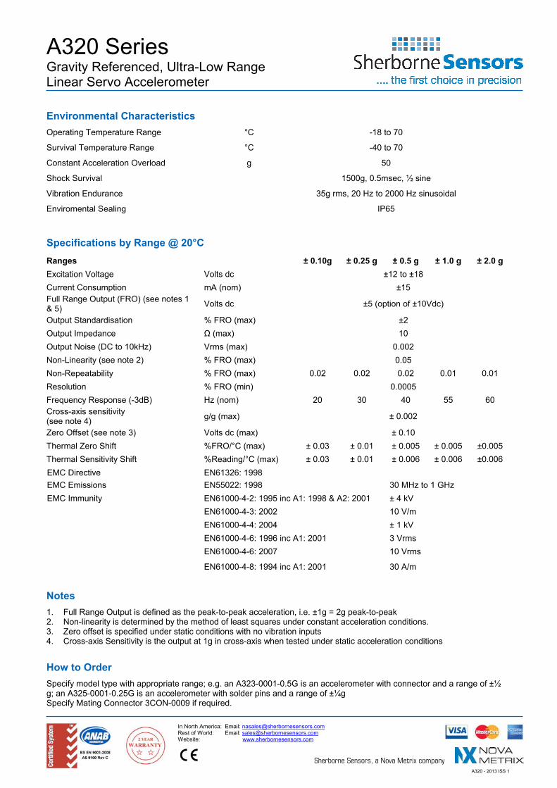
Environmental Characteristics Operating Temperature Range °C -18 to 70
Survival Temperature Range °C -40 to 70
Constant Acceleration Overload g 50
Shock Survival 1500g, 0.5msec, ½ sine
Vibration Endurance 35g rms, 20 Hz to 2000 Hz sinusoidal
Enviromental Sealing IP65
Specifications by Range @ 20°C Ranges ± 0.10g ± 0.25 g ± 0.5 g ± 1.0 g ± 2.0 g Excitation Voltage Volts dc ±12 to ±18 Current Consumption mA (nom) ±15 Full Range Output (FRO) (see notes 1 & 5) Volts dc ±5 (option of ±10Vdc)
Output Standardisation % FRO (max) ±2 Output Impedance Ω (max) 10 Output Noise (DC to 10kHz) Vrms (max) 0.002 Non-Linearity (see note 2) % FRO (max) 0.05 Non-Repeatability % FRO (max) 0.02 0.02 0.02 0.01 0.01 Resolution % FRO (min) 0.0005 Frequency Response (-3dB) Hz (nom) 20 30 40 55 60 Cross-axis sensitivity (see note 4) g/g (max) ± 0.002
Zero Offset (see note 3) Volts dc (max) ± 0.10 Thermal Zero Shift %FRO/°C (max) ± 0.03 ± 0.01 ± 0.005 ± 0.005 ±0.005 Thermal Sensitivity Shift %Reading/°C (max) ± 0.03 ± 0.01 ± 0.006 ± 0.006 ±0.006 EMC Directive EN61326: 1998 EMC Emissions EN55022: 1998 30 MHz to 1 GHz EMC Immunity EN61000-4-2: 1995 inc A1: 1998 & A2: 2001 ± 4 kV EN61000-4-3: 2002 10 V/m EN61000-4-4: 2004 ± 1 kV EN61000-4-6: 1996 inc A1: 2001 3 Vrms EN61000-4-6: 2007 10 Vrms EN61000-4-8: 1994 inc A1: 2001 30 A/m
Notes 1. Full Range Output is defined as the peak-to-peak acceleration, i.e. ±1g = 2g peak-to-peak 2. Non-linearity is determined by the method of least squares under constant acceleration conditions. 3. Zero offset is specified under static conditions with no vibration inputs 4. Cross-axis Sensitivity is the output at 1g in cross-axis when tested under static acceleration conditions
How to Order Specify model type with appropriate range; e.g. an A323-0001-0.5G is an accelerometer with connector and a range of ±½ g; an A325-0001-0.25G is an accelerometer with solder pins and a range of ±¼g Specify Mating Connector 3CON-0009 if required.
Recommended