Aalborg Universitet
Energy performance requirements for new buildings in 11 countries from CentralEuropeExemplary comparison of three buildings
Loga, Tobias; Knissel, Jens; Diefenbach, Nikolaus; Grim, Margot; Vimmr, Tomás; Popiolek,Malgorzata; Spets, Karin; Wittchen, Kim Bjarne; Bergsøe, Niels Christian; Hitchin, Roger;Yan, Vicky; van Cruchten, Gerelle; Berben, Joris; Tilmans, Antoine; Van Orshoven, Dirk;Viktor, Sven; Lichtmess, Markus; Despretz, Hubert
Publication date:2008
Document VersionPublisher's PDF, also known as Version of record
Link to publication from Aalborg University
Citation for published version (APA):Loga, T., Knissel, J., Diefenbach, N., Grim, M., Vimmr, T., Popiolek, M., Spets, K., Wittchen, K. B., Bergsøe, N.C., Hitchin, R., Yan, V., van Cruchten, G., Berben, J., Tilmans, A., Van Orshoven, D., Viktor, S., Lichtmess, M.,& Despretz, H. (2008). Energy performance requirements for new buildings in 11 countries from Central Europe:Exemplary comparison of three buildings. Institut Wohnen und Umwelt.
General rightsCopyright and moral rights for the publications made accessible in the public portal are retained by the authors and/or other copyright ownersand it is a condition of accessing publications that users recognise and abide by the legal requirements associated with these rights.
? Users may download and print one copy of any publication from the public portal for the purpose of private study or research. ? You may not further distribute the material or use it for any profit-making activity or commercial gain ? You may freely distribute the URL identifying the publication in the public portal ?
Take down policyIf you believe that this document breaches copyright please contact us at [email protected] providing details, and we will remove access tothe work immediately and investigate your claim.
Downloaded from vbn.aau.dk on: March 22, 2020
de
at
cz
INSTITUT WOHNEN
UND UMWELT GmbH
Annastraße 15
D-64285 Darmstadt / GERMANY
Fon: ++49 / (0)6151/2904-0
Fax: ++49 / (0)6151/2904-97
eMail: [email protected]
Internet: www.iwu.de
pl
Energy performance requirements for new buildings in 11 countries from Central Europe – Exemplary Comparison of three buildings se
dk performed on behalf of the German Federal Office for Building and Regional Planning (Bundesamt für Bauwesen und Raumordnung, Bonn) uk
Darmstadt/Germany, 5th December 2008
nl
be
lu
fr
Energy performance requirements for new buildings in 11 countries from Central Europe – Exemplary Comparison of three buildings performed on behalf of the German Federal Office for Building and Regional Planning (Bundesamt für Bauwesen und Raumordnung, Bonn) / German project title: „Energiesparrecht im mitteleuropäischen Vergleich – energetische Anforderungen an Neubauten“ (Vertrag Z 6 – 10.08.17.7-07.16)
Authors: Tobias Loga Dr. Jens Knissel Dr. Nikolaus Diefenbach
With the collaboration of: Margot Grim e7 – Energie-Markt-Analyse, Austria
Tomáš Vimmr Stu-k, Czech Republic
Małgorzata Popiołek NAPE, Poland
Karin Spets Mälardalens University, Sweden
Kim B. Wittchen / Niels Christian Bergsøe, SBi (Danish Building Research Institute), Denmark
Roger Hitchin / Vicky Yan, BRE (Building Research Establishment), UK
Gerelle van Cruchten / Joris Berben BuildDesk / Netherlands
Antoine Tilmans / Dirk Van Orshoven BBRI (Belgian Building Research Institute), Belgium
Sven Viktor / Markus Lichtmeß Goblet Lavandier & Associés S.A., Luxembourg
Hubert Despretz ADEME (Agence de l'Environnement et de la Maîtrise de l'Energie), France
Reprographic technique: Reda Hatteh
INSTITUT WOHNEN UND UMWELT GMBH
Darmstadt, 5th December 2008
ISBN: $$
IWU purchase order number: $$
2
Content Page
1 Summary......................................................................................................................................5
2 About the project.........................................................................................................................6
3 Methodical approach ..................................................................................................................7
3.1 Proceeding.........................................................................................................................7
3.2 Limits of evidence ..............................................................................................................9
4 Model Building 1: semi-detached single family house..........................................................11
4.1 Thermal envelope ............................................................................................................11
4.2 Types of supply systems .................................................................................................12
4.3 Results for the thermal quality of the envelope................................................................13
4.4 Primary energy demand (according to German regulations)...........................................16
5 Model Building 2: multi-family house......................................................................................18
5.1 Thermal Envelope............................................................................................................18
5.2 Types of supply systems .................................................................................................20
5.3 Results for the thermal quality of the envelope................................................................21
5.4 Primary energy demand (according to German regulations)...........................................23
6 Model Building 3: School .........................................................................................................25
6.1 Thermal envelope ............................................................................................................25
6.2 Types of supply systems .................................................................................................27
6.3 Results for the thermal quality of the envelope................................................................28
6.4 Primary energy demand (according to German regulations)...........................................30
7 Résumé ......................................................................................................................................32
3
Page
APPENDIX.....................................................................................................................................A-1
Appendix 1: Definition of Model Building 1 – semi-detached single family house ..............A-1
Appendix 1a: Plans ...................................................................................................................A-1
Appendix 1b: Detailed envelope area calculation (external dimensions) ..................................A-9
Appendix 1c: Definition of the supply system types ................................................................A-10
Appendix 1d: Country sheets ..................................................................................................A-15
Appendix 2: Definition of Model Building 2 – multi-family house........................................A-27
Appendix 2a: Plans .................................................................................................................A-27
Appendix 2b: Detailed envelope area calculation (external dimensions) ................................A-38
Appendix 2c: Definition of the supply system types ................................................................A-39
Appendix 2d: Country sheets ..................................................................................................A-44
Appendix 3: Definition of Model Building 3 – school ............................................................A-56
Appendix 3a: Plans .................................................................................................................A-56
Appendix 3b: Detailed envelope area calculation (external dimensions) ................................A-63
Appendix 3c: Definition of the supply system types ................................................................A-64
Appendix 3d: Country sheets ..................................................................................................A-67
4
Energy Performance Requirements for New Buildings – Exemplary Comparison
1 Summary
The objective of the present comparison study is to show which energy efficiency require-ments have to be complied in different European countries when a new building is going to be constructed. For this purpose three Model Buildings were defined: a single-family house, a multi-family house and a school building. For each involved country (or region) the energy quality of the thermal envelope was determined which is necessary in order to just comply with the building code. Due to requirements on the overall energy performance the requested envelope quality usually depends also on the type of heat supply system or energy carrier. Therefore the systems were varied in a parameter study. The main result for each of the three Model Buildings is a comparison table which shows the heat transfer coefficient by transmission (a sort of mean U-value) for the different countries differenti-ated by supply system types. In a final step the primary energy demand according to the German regulation (EnEV 2007) was calculated for every envelope/system combination of the different countries. This allows a comparison of buildings with different supply systems. The study was performed by experts from 11 European member states: Germany, Austria, Czech Republic, Poland, Sweden, Denmark, UK, The Netherlands, Belgium, Luxembourg and France.
5

Energy Performance Requirements for New Buildings – Exemplary Comparison
2 About the project
In Germany the transposition of the Energy Performance of Buildings Directive (EPBD) was per-formed by an amendment of the German Energy Saving Ordinance (Energieeinsparverordnung EnEV) in the year 2007. During this process formal and methodological changes were applied whereas the requirements remained the same. In year 2007 the German government announced to undertake a new revision which mainly will introduce a higher energy performance mandatory for new and refurbished buildings. In the discussion about tightening the requirements in Germany the question often arises which energy efficiency standards are applied in other European coun-tries with comparable climatic conditions. The present study aims at giving some more transpar-ency in this field.
The concrete objective of the project is to compare the energy performance requirements for new buildings in Germany with those of several other European countries with similar climate condi-tions. Due to the very different methods and traditions it is clear that an exact comparison between the countries will not be possible. Therefore this study is based on example buildings and certain assumptions that have been chosen by IWU and which certainly reflect a specific (German) per-spective. Certainly it would be possible to select other methodical approaches and maybe the re-sults could be (slightly) different.
The question to be answered by each partner is: Which U-values have to be chosen for roof, walls, windows and floor if a given building is supposed to just comply with the requirements for new buildings in the respective country. Since generally the level of insulation indirectly depends on the building geometry and of the supply system type these parameters are varied. In the framework of the project three example buildings are analysed: a single family house (which is the subject of this report), a multi family house and a school building. Furthermore the installation of several different supply systems is assumed.
The analysis focuses on the comparison of the tangible quality of the building envelope defined by the national regulations. Neither the different certification methodologies nor the aspects of practi-cal implementation of these standards are a topic of the study.
The analysis is performed on behalf of the German Federal Office for Building and Regional Plan-ning (BBR) by IWU (Institut Wohnen und Umwelt / Institute for Housing and environment) with the assistance of the following partners:
6
Energy Performance Requirements for New Buildings – Exemplary Comparison
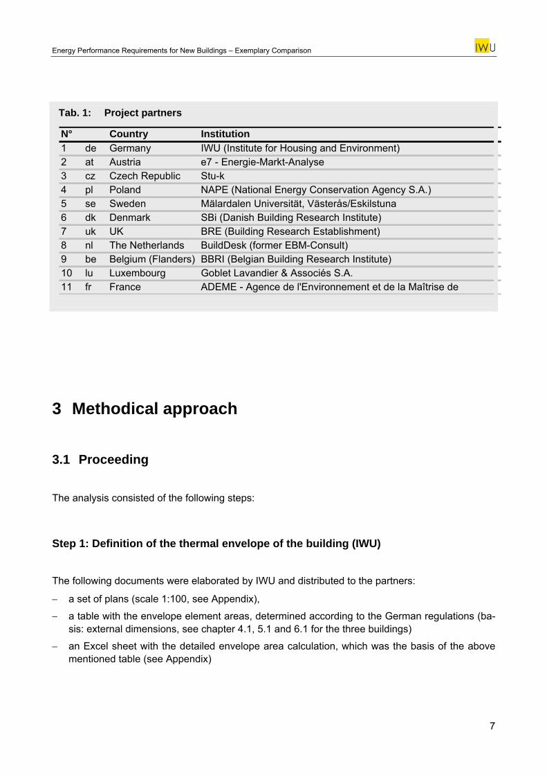
Tab. 1: Project partners
N° Country Institution1 de Germany IWU (Institute for Housing and Environment)2 at Austria e7 - Energie-Markt-Analyse3 cz Czech Republic Stu-k 4 pl Poland NAPE (National Energy Conservation Agency S.A.)5 se Sweden Mälardalen Universität, Västerås/Eskilstuna6 dk Denmark SBi (Danish Building Research Institute)7 uk UK BRE (Building Research Establishment)8 nl The Netherlands BuildDesk (former EBM-Consult)9 be Belgium (Flanders) BBRI (Belgian Building Research Institute)10 lu Luxembourg Goblet Lavandier & Associés S.A.11 fr France ADEME - Agence de l'Environnement et de la Maîtrise de
3 Methodical approach
3.1 Proceeding
The analysis consisted of the following steps:
Step 1: Definition of the thermal envelope of the building (IWU)
The following documents were elaborated by IWU and distributed to the partners:
− a set of plans (scale 1:100, see Appendix),
− a table with the envelope element areas, determined according to the German regulations (ba-sis: external dimensions, see chapter 4.1, 5.1 and 6.1 for the three buildings)
− an Excel sheet with the detailed envelope area calculation, which was the basis of the above mentioned table (see Appendix)
7
Energy Performance Requirements for New Buildings – Exemplary Comparison
Step 2: Definition of the supply system variants (IWU)
IWU defined a set of supply systems for each Model Building (see chapter 4.2, 5.2 and 6.2). The partners received a table defining the different variants on two levels (see Appendix):
− a determination of the type of the components, which was often sufficient for the calculation;
− detailed information about the components (for example thermal power of the heat generator, electric power of pumps, length and heat loss of heating pipes), which were to be used only in case that national standard values are not available.
Step 3: Determination of the U-values (all partners) Each partner was requested to determine the U-values which have to be chosen for this building in order to comply with the building code – under assumption of the different supply system variants.
The principles of this procedure were:
− In those countries in which the thermal envelope is not defined by the external dimensions the envelope area table delivered by IWU could not be used. The concerned partners were sup-posed to determine the envelope areas on their own by use of the building plans.
− For simplification purpose it was assumed that the thicknesses of the building envelope ele-ments do not depend on the U-value (the U-value variation can therefore be seen as a varia-tion of the thermal conductivity).
− The U-value for each construction element was supposed to be the “pure” thermal transmit-tance not including supplements or reductions caused by transmission losses at the border of the elements. (In case of the opaque elements the study may be see as a comparison of insu-lation thicknesses.)
− If there are different methods in a country the most common should be used (typically the most simple method).
− If for a country the requirements are different for certain regions a region had to be selected where the climate conditions are as close as possible to the German ones.
− If deviations from the building or system definitions were necessary these had to be docu-mented.
The results of this analysis was documented by each partner in a uniform sheet (see Appendix: “Country Sheets”)
8
Energy Performance Requirements for New Buildings – Exemplary Comparison
Step 4: Calculation of a simplified heat transfer coefficient by transmission and cross-country comparison (IWU) For purpose of comparison a weighted average of the U-values of the different construction ele-ments were calculated by IWU. For this weighting the external area was used. The result is a sort of simplified heat transfer coefficient by transmission.1 The calculation of these values can be found in the country sheets (Appendix), the results of the cross-country comparison are shown in chapter 4.3, 5.3 and 6.3.
Step 5: Calculation of the primary energy demand according to the German official method and cross-country comparison (IWU) In order to compare the total energy performance of the building variants from the different coun-tries the primary energy demand was calculated according to the rules of the German regulations (Energy Saving Ordinance / Energieeinsparverordnung EnEV 2007). The resulting values are shown in the chapters 4.4, 0 and 6.4.
3.2 Limits of evidence
The chosen method is capable to depict the level of national energy efficiency requirements in a concrete and exemplary way. Of course, the exactness and evidence of this comparison is limited since the results depend on factors which were not considered in this study:
• Number of Model Buildings: The example buildings considered in this study represent only a small fraction of possible building geometries. The dependence of the requirements from the surface to volume relation and from the building size is different for each country. In conse-quence the relation of the requirements between the different countries could possibly change if different buildings were considered.
• Definition of the thermal envelope: The definition of the thermal envelope in a unique way is not always possible, since the rules sometimes allow different solutions (cellar rooms, stair wells, garages, winter gardens, …). In order to avoid such uncertainties rather simple building ge-ometries were selected for this investigation (which may have effects on the requirement level, see above). A special problem is the energy balance calculation for an apartment building. In some countries the thermal envelope is considered to be the surface of the whole building, in others only the thermal envelope of the apartments are considered, in some countries there is
1 In case of a well designed building with minimized constructive thermal bridges this simplified heat transfer coefficient by transmis-
sion is very close to the real value including thermal bridging (to the experience of the authors). A precondition is that the envelope area determination is based on external dimensions.
9
Energy Performance Requirements for New Buildings – Exemplary Comparison
a mix of both approaches. In order to compare the U-values one of these approach has to be chosen. (In the present study the surface of the whole building was used.)
• Variety of methods in some countries: In some countries different proofs of conformity are per-mitted. Applying different methods will typically produce different results for the same building. (The rule for the present study was to use the most common method, which is typically one with a lesser effort.)
• Frequentness of supply system types in each country: The comparison of the results for the primary energy (calculated according the German EnEV) shows that the maximum allowable demand of non-renewable energy can be very different, depending on the system or energy carrier. For a comprehensive comparison of the countries information about the frequentness of the installed supply system types is necessary.
• Implementation in practice: The practical realisation of equally designed buildings may be dif-ferent from country to country. On the one hand the implementation of the building code cer-tainly depends on the control mechanisms applied by state. It may also depend on traditions of planning and quality assurance.
10
Energy Performance Requirements for New Buildings – Exemplary Comparison
4 Model Building 1: semi-detached single family house
4.1 Thermal envelope
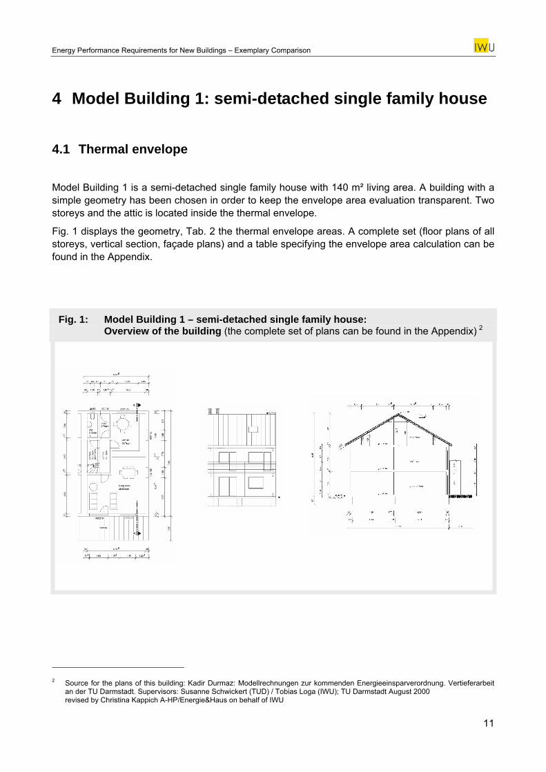
Model Building 1 is a semi-detached single family house with 140 m² living area. A building with a simple geometry has been chosen in order to keep the envelope area evaluation transparent. Two storeys and the attic is located inside the thermal envelope.
Fig. 1 displays the geometry, Tab. 2 the thermal envelope areas. A complete set (floor plans of all storeys, vertical section, façade plans) and a table specifying the envelope area calculation can be found in the Appendix.
Fig. 1: Model Building 1 – semi-detached single family house: Overview of the building (the complete set of plans can be found in the Appendix) 2
2 Source for the plans of this building: Kadir Durmaz: Modellrechnungen zur kommenden Energieeinsparverordnung. Vertieferarbeit
an der TU Darmstadt. Supervisors: Susanne Schwickert (TUD) / Tobias Loga (IWU); TU Darmstadt August 2000 revised by Christina Kappich A-HP/Energie&Haus on behalf of IWU
11
Energy Performance Requirements for New Buildings – Exemplary Comparison
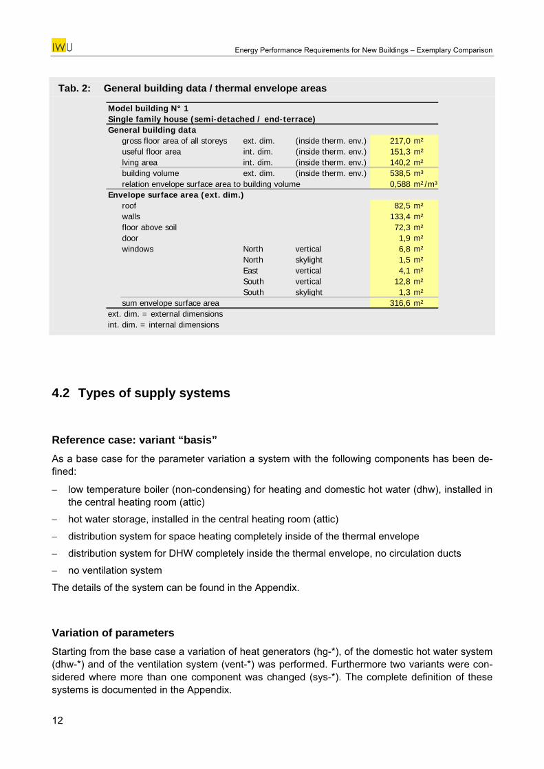
Tab. 2: General building data / thermal envelope areas
Model building N° 1Single family house (semi-detached / end-terrace)General building data
gross floor area of all storeys ext. dim. (inside therm. env.) 217,0 m²useful floor area int. dim. (inside therm. env.) 151,3 m²lving area int. dim. (inside therm. env.) 140,2 m²building volume ext. dim. (inside therm. env.) 538,5 m³relation envelope surface area to building volume 0,588 m²/m³
Envelope surface area (ext. dim.)roof 82,5 m²walls 133,4 m²floor above soil 72,3 m²door 1,9 m²windows North vertical 6,8 m²
North skylight 1,5 m²East vertical 4,1 m²South vertical 12,8 m²South skylight 1,3 m²
sum envelope surface area 316,6 m²ext. dim. = external dimensionsint. dim. = internal dimensions
4.2 Types of supply systems
Reference case: variant “basis” As a base case for the parameter variation a system with the following components has been de-fined:
− low temperature boiler (non-condensing) for heating and domestic hot water (dhw), installed in the central heating room (attic)
− hot water storage, installed in the central heating room (attic)
− distribution system for space heating completely inside of the thermal envelope
− distribution system for DHW completely inside the thermal envelope, no circulation ducts
− no ventilation system
The details of the system can be found in the Appendix.
Variation of parameters Starting from the base case a variation of heat generators (hg-*), of the domestic hot water system (dhw-*) and of the ventilation system (vent-*) was performed. Furthermore two variants were con-sidered where more than one component was changed (sys-*). The complete definition of these systems is documented in the Appendix.
12
Energy Performance Requirements for New Buildings – Exemplary Comparison
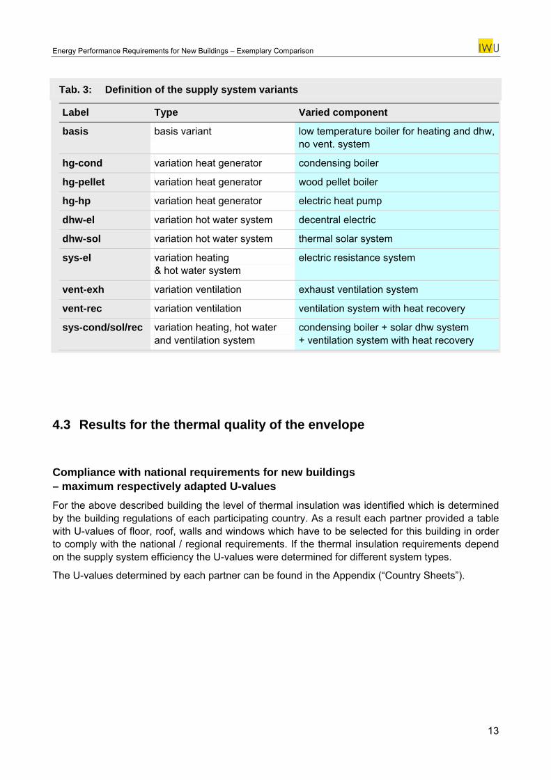
Tab. 3: Definition of the supply system variants
Label Type Varied component
basis basis variant low temperature boiler for heating and dhw, no vent. system
hg-cond variation heat generator condensing boiler
hg-pellet variation heat generator wood pellet boiler
hg-hp variation heat generator electric heat pump
dhw-el variation hot water system decentral electric
dhw-sol variation hot water system thermal solar system
sys-el variation heating & hot water system
electric resistance system
vent-exh variation ventilation exhaust ventilation system
vent-rec variation ventilation ventilation system with heat recovery
sys-cond/sol/rec variation heating, hot water and ventilation system
condensing boiler + solar dhw system + ventilation system with heat recovery
4.3 Results for the thermal quality of the envelope
Compliance with national requirements for new buildings – maximum respectively adapted U-values For the above described building the level of thermal insulation was identified which is determined by the building regulations of each participating country. As a result each partner provided a table with U-values of floor, roof, walls and windows which have to be selected for this building in order to comply with the national / regional requirements. If the thermal insulation requirements depend on the supply system efficiency the U-values were determined for different system types.
The U-values determined by each partner can be found in the Appendix (“Country Sheets”).
13
Energy Performance Requirements for New Buildings – Exemplary Comparison
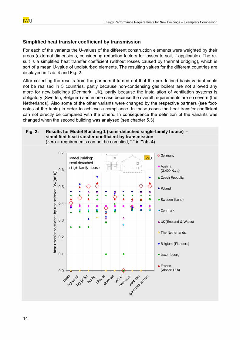
Simplified heat transfer coefficient by transmission For each of the variants the U-values of the different construction elements were weighted by their areas (external dimensions, considering reduction factors for losses to soil, if applicable). The re-sult is a simplified heat transfer coefficient (without losses caused by thermal bridging), which is sort of a mean U-value of undisturbed elements. The resulting values for the different countries are displayed in Tab. 4 and Fig. 2.
After collecting the results from the partners it turned out that the pre-defined basis variant could not be realised in 5 countries, partly because non-condensing gas boilers are not allowed any more for new buildings (Denmark, UK), partly because the installation of ventilation systems is obligatory (Sweden, Belgium) and in one case because the overall requirements are so severe (the Netherlands). Also some of the other variants were changed by the respective partners (see foot-notes at the table) in order to achieve a compliance. In these cases the heat transfer coefficient can not directly be compared with the others. In consequence the definition of the variants was changed when the second building was analysed (see chapter 5.3)
Fig. 2: Results for Model Building 1 (semi-detached single-family house) – simplified heat transfer coefficient by transmission (zero = requirements can not be complied, “-“ in Tab. 4)
0,0
0,1
0,2
0,3
0,4
0,5
0,6
0,7
basis
hg-co
nd
hg-pe
llet
hg-hp
dhw-el
dhw-so
l
sys-e
l
vent
-exh
vent
-rec
sys-c
ond/
sol/r
ec
heat
tra
nsfe
r co
effic
ient
by
tran
smis
sion
[W
/(m
²K)]
Germany
Austria (3.400 Kd/a)
Czech Republic
Poland
Sweden (Lund)
Denmark
UK (England & Wales)
The Netherlands
Belgium (Flanders)
Luxembourg
France (Alsace H1b)
Model Building:semi-detached single family house
14
Energy Performance Requirements for New Buildings – Exemplary Comparison
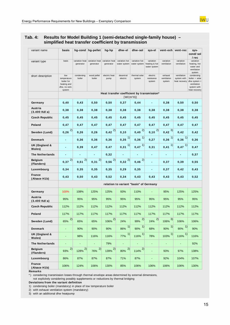
Tab. 4: Results for Model Building 1 (semi-detached single-family house) – simplified heat transfer coefficient by transmission
variant name basis hg-cond hg-pellet hg-hp dhw-el dhw-sol sys-el vent-exh vent-rec sys-cond/sol
/recvariant type basis variation heat
generatorvariation heat
generatorvariation heat
generatorvariation hot water system
variation hot water system
variation heating & hot water system
variation ventilation
variation ventilation
variation heating, hot water and ventilation
system
short description low temperature
boiler for heating and
dhw, no vent. system
condensing boiler
wood pellet boiler
electric heat pump
decentral electric
thermal solar system
electric resistance
system
exhaust ventilation
system
ventilation system with
heat recovery
condensing boiler + solar dhw system +
ventilation system with
heat recovery
Heat transfer coefficient by transmission*[W/(m²K)]
Germany 0,40 0,43 0,50 0,50 0,37 0,44 - 0,38 0,50 0,50
Austria (3.400 Kd/a)
0,38 0,38 0,38 0,38 0,38 0,38 0,38 0,38 0,38 0,38
Czech Republic 0,45 0,45 0,45 0,45 0,45 0,45 0,45 0,45 0,45 0,45
Poland 0,47 0,47 0,47 0,47 0,47 0,47 0,47 0,47 0,47 0,47
Sweden (Lund) 0,26 0,26 0,26 0,42 0,10 0,40 0,10 0,42 0,42 0,42
Denmark - 0,36 0,36 0,36 0,35 0,36 0,27 0,36 0,36 0,36
UK (England & Wales)
- 0,39 0,47 0,47 0,31 0,47 0,31 0,41 0,47 0,47
The Netherlands - - - 0,32 - - - - - 0,3
Belgium (Flanders)
0,37 0,51 0,31 0,56 0,32 0,46 - 0,37 0,39 0,55
Luxembourg 0,34 0,35 0,35 0,35 0,29 0,35 - 0,37 0,42 0,43
France (Alsace H1b)
0,43 0,50 0,43 0,52 0,34 0,43 0,43 0,43 0,43 0,52
relation to variant "basis" of Germany
Germany
7
108% 125% 125% 93% 110% - 95% 125% 125%
Austria
100%
(3.400 Kd/a)95% 95% 95% 95% 95% 95% 95% 95% 95% 95%
Czech Republic 112% 112% 112% 112% 112% 112% 112% 112% 112% 112%
Poland 117% 117% 117% 117% 117% 117% 117% 117% 117% 117%
Sweden (Lund) 65% 65% 65% 106% 24% 99% 24% 106% 106% 106%
Denmark - 90% 90% 90% 86% 90% 68% 90% 90% 90%
UK (England & Wales)
- 98% 116% 116% 77% 116% 78% 103% 116% 116%
The Netherlands - - - 79% - - - - - 92%
Belgium (Flanders)
93% 128% 76% 139% 80% 114% - 93% 97% 138%
Luxembourg 86% 87% 87% 87% 71% 87% - 92% 104% 107%
France (Alsace H1b)
106% 124% 106% 130% 85% 106% 106% 106% 106% 130%
Remarks*) considering transmission losses through thermal envelope areas determined by external dimensions, not explicitely considering possibly supplements or reductions by thermal bridgingDeviations from the variant definition1) condensing boiler (mandatory) in place of low temperature boiler2) with exhaust ventilation system (mandatory)3) with an additional dhw heatpump
2) 2) 2) 2)
1) 1) 1) 1)
1) 1) 1) 1)
2) 2) 2) 2) 2) 2)
3)
2) 2) 2) 2)
1) 1) 1) 1)
1) 1) 1) 1)
2) 2) 2) 2) 2) 2)
3)
15
Energy Performance Requirements for New Buildings – Exemplary Comparison
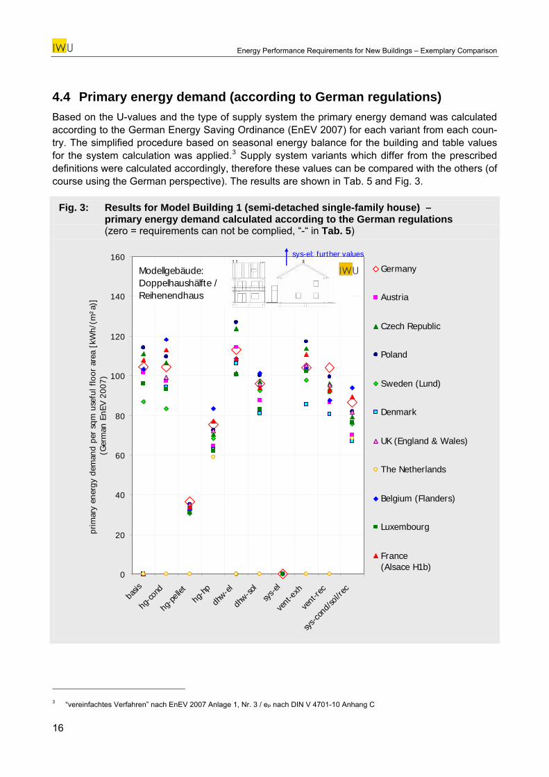
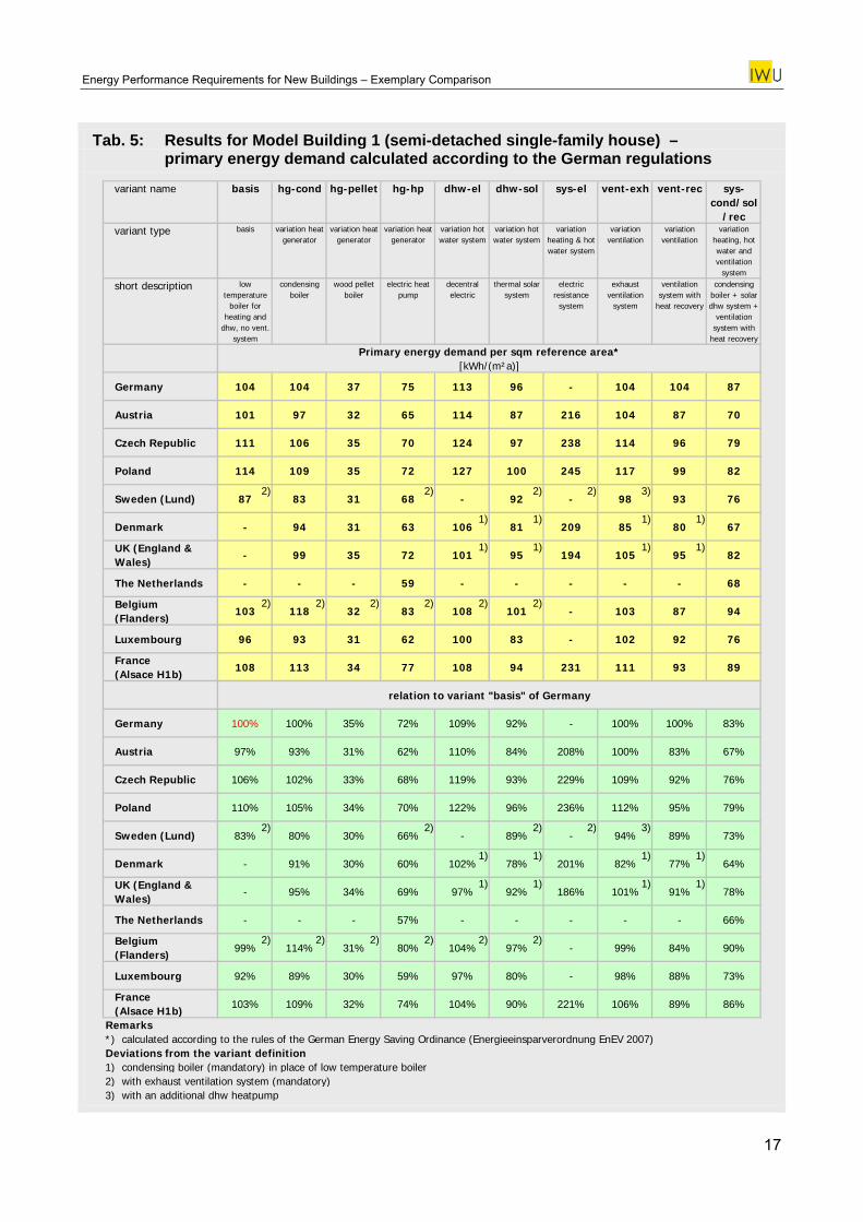
4.4 Primary energy demand (according to German regulations) Based on the U-values and the type of supply system the primary energy demand was calculated according to the German Energy Saving Ordinance (EnEV 2007) for each variant from each coun-try. The simplified procedure based on seasonal energy balance for the building and table values for the system calculation was applied.3 Supply system variants which differ from the prescribed definitions were calculated accordingly, therefore these values can be compared with the others (of course using the German perspective). The results are shown in Tab. 5 and Fig. 3.
Fig. 3: Results for Model Building 1 (semi-detached single-family house) – primary energy demand calculated according to the German regulations (zero = requirements can not be complied, “-“ in Tab. 5)
0
20
40
60
80
100
120
140
160
basis
hg-co
nd
hg-p
ellet
hg-h
p
dhw-e
l
dhw-so
lsy
s-el
vent
-exh
vent
-rec
sys-c
ond/
sol/r
ec
prim
ary
ener
gy d
eman
d pe
r sq
m u
sefu
l flo
or a
rea
[kW
h/(m
²a)]
(G
erm
an E
nEV
2007
)
Germany
Austria
Czech Republic
Poland
Sweden (Lund)
Denmark
UK (England & Wales)
The Netherlands
Belgium (Flanders)
Luxembourg
France (Alsace H1b)
Modellgebäude:Doppelhaushälfte / Reihenendhaus
sys-el: further values
3 “vereinfachtes Verfahren” nach EnEV 2007 Anlage 1, Nr. 3 / eP nach DIN V 4701-10 Anhang C
16
Energy Performance Requirements for New Buildings – Exemplary Comparison
Tab. 5: Results for Model Building 1 (semi-detached single-family house) – primary energy demand calculated according to the German regulations
variant name basis hg-cond hg-pellet hg-hp dhw-el dhw-sol sys-el vent-exh vent-rec sys-cond/sol
/recvariant type basis variation heat
generatorvariation heat
generatorvariation heat
generatorvariation hot water system
variation hot water system
variation heating & hot water system
variation ventilation
variation ventilation
variation heating, hot water and ventilation
system
short description low temperature
boiler for heating and
dhw, no vent. system
condensing boiler
wood pellet boiler
electric heat pump
decentral electric
thermal solar system
electric resistance
system
exhaust ventilation
system
ventilation system with
heat recovery
condensing boiler + solar dhw system +
ventilation system with
heat recovery
Primary energy demand per sqm reference area*[kWh/(m²a)]
Germany 104 104 37 75 113 96 - 104 104 87
Austria 101 97 32 65 114 87 216 104 87 70
Czech Republic 111 106 35 70 124 97 238 114 96 79
Poland 114 109 35 72 127 100 245 117 99 82
Sweden (Lund) 87 83 31 68 - 92 - 98 93 76
Denmark - 94 31 63 106 81 209 85 80 67
UK (England & Wales)
- 99 35 72 101 95 194 105 95 82
The Netherlands - - - 59 - - - - - 68
Belgium (Flanders)
103 118 32 83 108 101 - 103 87 94
Luxembourg 96 93 31 62 100 83 - 102 92 76
France (Alsace H1b)
108 113 34 77 108 94 231 111 93 89
relation to variant "basis" of Germany
Germany 100% 100% 35% 72% 109% 92% - 100% 100% 83%
Austria 97% 93% 31% 62% 110% 84% 208% 100% 83% 67%
Czech Republic 106% 102% 33% 68% 119% 93% 229% 109% 92% 76%
Poland 110% 105% 34% 70% 122% 96% 236% 112% 95% 79%
Sweden (Lund) 83% 80% 30% 66% - 89% - 94% 89% 73%
Denmark - 91% 30% 60% 102% 78% 201% 82% 77% 64%
UK (England & Wales)
- 95% 34% 69% 97% 92% 186% 101% 91% 78%
The Netherlands - - - 57% - - - - - 66%
Belgium (Flanders)
99% 114% 31% 80% 104% 97% - 99% 84% 90%
Luxembourg 92% 89% 30% 59% 97% 80% - 98% 88% 73%
France (Alsace H1b)
103% 109% 32% 74% 104% 90% 221% 106% 89% 86%
Remarks*) calculated according to the rules of the German Energy Saving Ordinance (Energieeinsparverordnung EnEV 2007)Deviations from the variant definition1
2) 2) 2) 2)
1) 1) 1) 1)
1) 1) 1) 1)
2) 2) 2) 2) 2) 2)
3)
2) 2) 2) 2)
1) 1) 1) 1)
1) 1) 1) 1)
2) 2) 2) 2) 2) 2)
3)
) condensing boiler (mandatory) in place of low temperature boiler2) with exhaust ventilation system (mandatory)3) with an additional dhw heatpump
17

Energy Performance Requirements for New Buildings – Exemplary Comparison
5 Model Building 2: multi-family house
5.1 Thermal Envelope Model Building 2 is a multi-family house with 3 storeys plus conditioned attic storey. The cellar is not heated. The living area of the 7 apartments is 461 m² in total.
Fig. 4: Model Building 2 – multi-family house: Overview of the building (the complete set of plans can be found in the Appendix) 4
4 Source for the plans of this building: Kadir Durmaz: Modellrechnungen zur kommenden Energieeinsparverordnung. Vertieferarbeit
an der TU Darmstadt. Supervisors: Susanne Schwickert (TUD) / Tobias Loga (IWU); TU Darmstadt August 2000 revised by Christina Kappich A-HP/Energie&Haus on behalf of IWU
18
Energy Performance Requirements for New Buildings – Exemplary Comparison
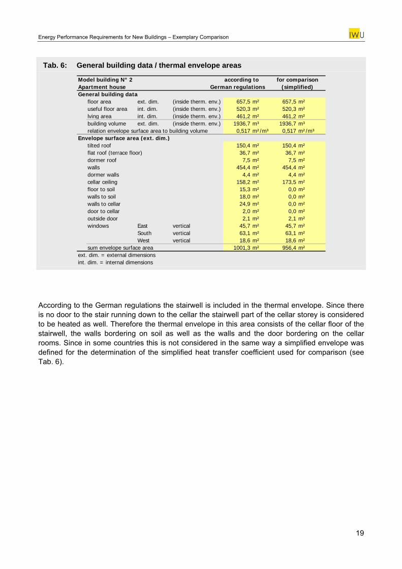
Tab. 6: General building data / thermal envelope areas
Model building N° 2 according to for comparisonApartment house German regulations (simplified)General building data
floor area ext. dim. (inside therm. env.) 657,5 m² 657,5 m²useful floor area int. dim. (inside therm. env.) 520,3 m² 520,3 m²lving area int. dim. (inside therm. env.) 461,2 m² 461,2 m²building volume ext. dim. (inside therm. env.) 1936,7 m³ 1936,7 m³relation envelope surface area to building volume 0,517 m²/m³ 0,517 m²/m³
Envelope surface area (ext. dim.)tilted roof 150,4 m² 150,4 m²flat roof (terrace floor) 36,7 m² 36,7 m²dormer roof 7,5 m² 7,5 m²walls 454,4 m² 454,4 m²dormer walls 4,4 m² 4,4 m²cellar ceiling 158,2 m² 173,5 m²floor to soil 15,3 m² 0,0 m²walls to soil 18,0 m² 0,0 m²walls to cellar 24,9 m² 0,0 m²door to cellar 2,0 m² 0,0 m²outside door 2,1 m² 2,1 m²windows East vertical 45,7 m² 45,7 m²
South vertical 63,1 m² 63,1 m²West vertical 18,6 m² 18,6 m²
sum envelope surface area 1001,3 m² 956,4 m²ext. dim. = external dimensionsint. dim. = internal dimensions
According to the German regulations the stairwell is included in the thermal envelope. Since there is no door to the stair running down to the cellar the stairwell part of the cellar storey is considered to be heated as well. Therefore the thermal envelope in this area consists of the cellar floor of the stairwell, the walls bordering on soil as well as the walls and the door bordering on the cellar rooms. Since in some countries this is not considered in the same way a simplified envelope was defined for the determination of the simplified heat transfer coefficient used for comparison (see Tab. 6).
19
Energy Performance Requirements for New Buildings – Exemplary Comparison
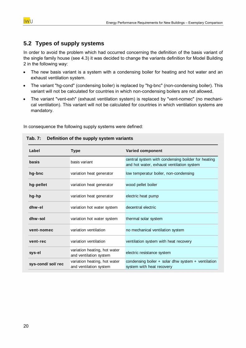
5.2 Types of supply systems In order to avoid the problem which had occurred concerning the definition of the basis variant of the single family house (see 4.3) it was decided to change the variants definition for Model Building 2 in the following way:
• The new basis variant is a system with a condensing boiler for heating and hot water and an exhaust ventilation system.
• The variant "hg-cond" (condensing boiler) is replaced by "hg-bnc" (non-condensing boiler). This variant will not be calculated for countries in which non-condensing boilers are not allowed.
• The variant "vent-exh" (exhaust ventilation system) is replaced by "vent-nomec" (no mechani-cal ventilation). This variant will not be calculated for countries in which ventilation systems are mandatory.
In consequence the following supply systems were defined:
Tab. 7: Definition of the supply system variants
Label Type Varied component
basis basis variantcentral system with condensing boilder for heating and hot water, exhaust ventilation system
hg-bnc variation heat generator low temperatur boiler, non-condensing
hg-pellet variation heat generator wood pellet boiler
hg-hp variation heat generator electric heat pump
dhw-el variation hot water system decentral electric
dhw-sol variation hot water system thermal solar system
vent-nomec variation ventilation no mechanical ventilation system
vent-rec variation ventilation ventilation system with heat recovery
sys-elvariation heating, hot water and ventilation system
electric resistance system
sys-cond/sol/recvariation heating, hot water and ventilation system
condensing boiler + solar dhw system + ventilation system with heat recovery
20
Energy Performance Requirements for New Buildings – Exemplary Comparison
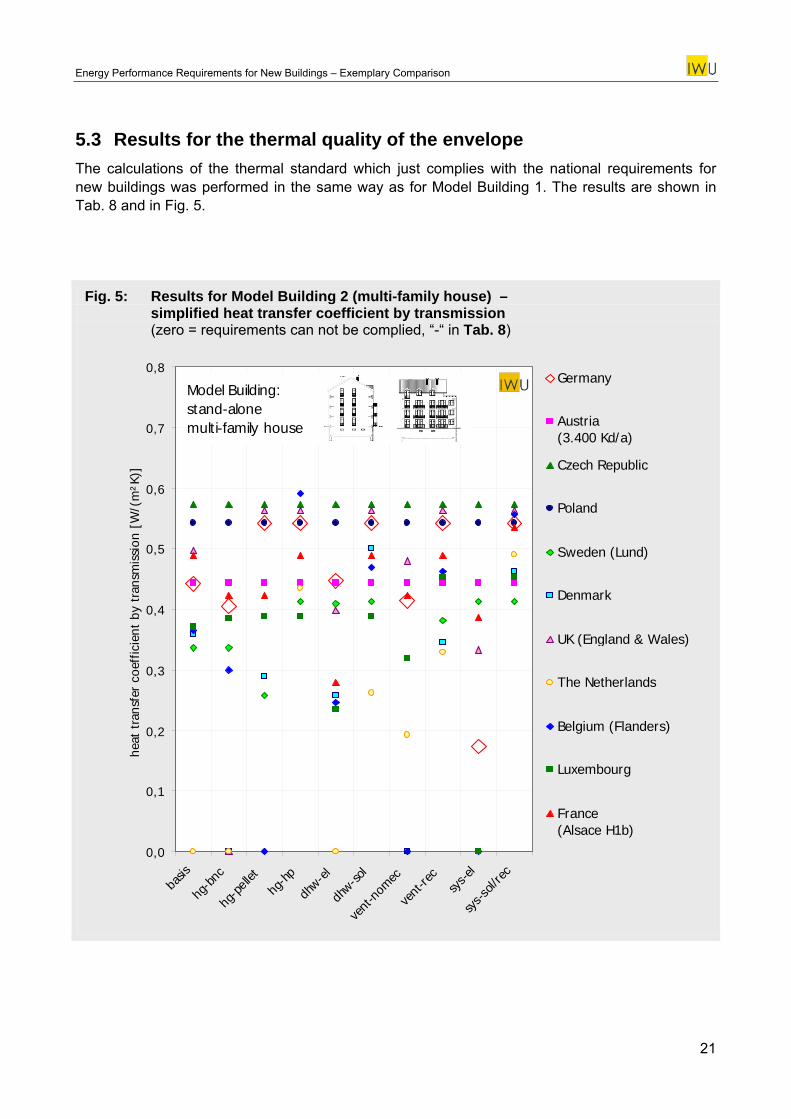
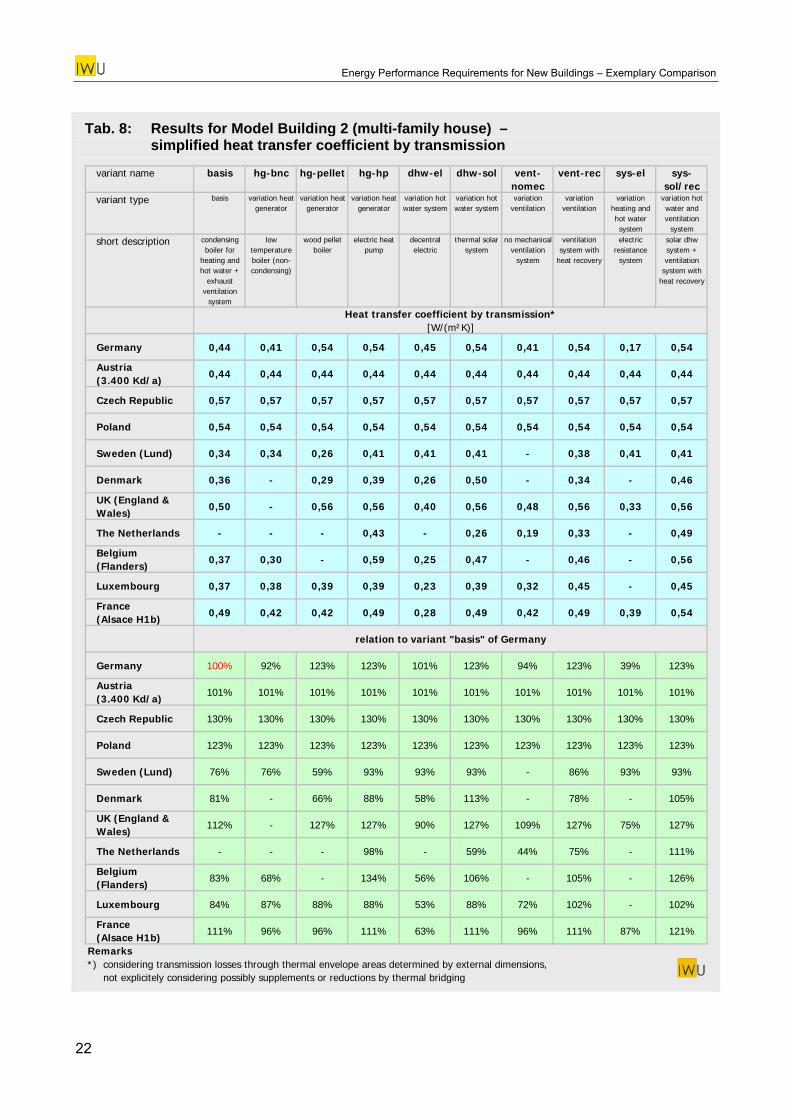
5.3 Results for the thermal quality of the envelope The calculations of the thermal standard which just complies with the national requirements for new buildings was performed in the same way as for Model Building 1. The results are shown in Tab. 8 and in Fig. 5.
Fig. 5: Results for Model Building 2 (multi-family house) – simplified heat transfer coefficient by transmission (zero = requirements can not be complied, “-“ in Tab. 8)
0,0
0,1
0,2
0,3
0,4
0,5
0,6
0,7
0,8
basis
hg-b
nc
hg-p
ellet
hg-h
p
dhw-e
l
dhw-so
l
vent
-nom
ec
vent
-rec
sys-e
l
sys-s
ol/re
c
heat
tra
nsfe
r co
effic
ient
by
tran
smis
sion
[W
/(m
²K)]
Germany
Austria (3.400 Kd/a)
Czech Republic
Poland
Sweden (Lund)
Denmark
UK (England & Wales)
The Netherlands
Belgium (Flanders)
Luxembourg
France (Alsace H1b)
Model Building:stand-alonemulti-family house
21
Energy Performance Requirements for New Buildings – Exemplary Comparison
Tab. 8: Results for Model Building 2 (multi-family house) – simplified heat transfer coefficient by transmission
variant name basis hg-bnc hg-pellet hg-hp dhw-el dhw-sol vent-nomec
vent-rec sys-el sys-sol/rec
variant type basis variation heat generator
variation heat generator
variation heat generator
variation hot water system
variation hot water system
variation ventilation
variation ventilation
variation heating and hot water system
variation hot water and ventilation
system
short description condensing boiler for
heating and hot water +
exhaust ventilation
system
low temperature boiler (non-condensing)
wood pellet boiler
electric heat pump
decentral electric
thermal solar system
no mechanical ventilation
system
ventilation system with
heat recovery
electric resistance
system
solar dhw system + ventilation
system with heat recovery
Heat transfer coefficient by transmission*[W/(m²K)]
Germany 0,44 0,41 0,54 0,54 0,45 0,54 0,41 0,54 0,17 0,54
Austria (3.400 Kd/a)
0,44 0,44 0,44 0,44 0,44 0,44 0,44 0,44 0,44 0,44
Czech Republic 0,57 0,57 0,57 0,57 0,57 0,57 0,57 0,57 0,57 0,57
Poland 0,54 0,54 0,54 0,54 0,54 0,54 0,54 0,54 0,54 0,54
Sweden (Lund) 0,34 0,34 0,26 0,41 0,41 0,41 - 0,38 0,41 0,41
Denmark 0,36 - 0,29 0,39 0,26 0,50 - 0,34 - 0,46
UK (England & Wales)
0,50 - 0,56 0,56 0,40 0,56 0,48 0,56 0,33 0,56
The Netherlands - - - 0,43 - 0,26 0,19 0,33 - 0,49
Belgium (Flanders)
0,37 0,30 - 0,59 0,25 0,47 - 0,46 - 0,56
Luxembourg 0,37 0,38 0,39 0,39 0,23 0,39 0,32 0,45 - 0,45
France (Alsace H1b)
0,49 0,42 0,42 0,49 0,28 0,49 0,42 0,49 0,39 0,54
relation to variant "basis" of Germany
Germany 100% 92% 123% 123% 101% 123% 94% 123% 39% 123%
Austria (3.400 Kd/a)
101% 101% 101% 101% 101% 101% 101% 101% 101% 101%
Czech Republic 130% 130% 130% 130% 130% 130% 130% 130% 130% 130%
Poland 123% 123% 123% 123% 123% 123% 123% 123% 123% 123%
Sweden (Lund) 76% 76% 59% 93% 93% 93% - 86% 93% 93%
Denmark 81% - 66% 88% 58% 113% - 78% - 105%
UK (England & Wales)
112% - 127% 127% 90% 127% 109% 127% 75% 127%
The Netherlands - - - 98% - 59% 44% 75% - 111%
Belgium (Flanders)
83% 68% - 134% 56% 106% - 105% - 126%
Luxembourg 84% 87% 88% 88% 53% 88% 72% 102% - 102%
France (Alsace H1b)
111% 96% 96% 111% 63% 111% 96% 111% 87% 121%
Remarks*) considering transmission losses through thermal envelope areas determined by external dimensions, not explicitely considering possibly supplements or reductions by thermal bridging
22
Energy Performance Requirements for New Buildings – Exemplary Comparison
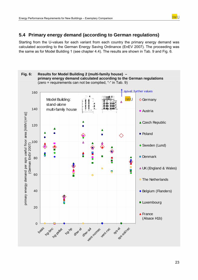
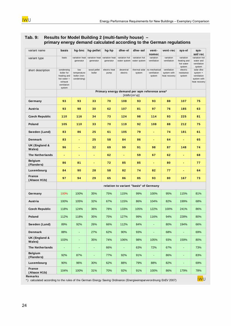
5.4 Primary energy demand (according to German regulations) Starting from the U-values for each variant from each country the primary energy demand was calculated according to the German Energy Saving Ordinance (EnEV 2007). The proceeding was the same as for Model Building 1 (see chapter 4.4). The results are shown in Tab. 9 and Fig. 6.
Fig. 6: Results for Model Building 2 (multi-family house) – primary energy demand calculated according to the German regulations (zero = requirements can not be complied, “-“ in Tab. 9)
0
20
40
60
80
100
120
140
160
basis
hg-b
nc
hg-p
ellet
hg-h
p
dhw-e
l
dhw-so
l
vent
-nom
ec
vent
-rec
sys-e
l
sys-s
ol/re
c
prim
ary
ener
gy d
eman
d pe
r sq
m u
sefu
l flo
or a
rea
[kW
h/(m
²a)]
(Ger
man
EnE
V 20
07)
Germany
Austria
Czech Republic
Poland
Sweden (Lund)
Denmark
UK (England & Wales)
The Netherlands
Belgium (Flanders)
Luxembourg
France (Alsace H1b)
Model Building:stand-alonemulti-family house
sys-el: further values
23
Energy Performance Requirements for New Buildings – Exemplary Comparison
Tab. 9: Results for Model Building 2 (multi-family house) – primary energy demand calculated according to the German regulations
variant name basis hg-bnc hg-pellet hg-hp dhw-el dhw-sol vent-nomec
vent-rec sys-el sys-sol/rec
variant type basis variation heat generator
variation heat generator
variation heat generator
variation hot water system
variation hot water system
variation ventilation
variation ventilation
variation heating and hot water system
variation hot water and ventilation
system
short description condensing boiler for
heating and hot water +
exhaust ventilation
system
low temperature boiler (non-condensing)
wood pellet boiler
electric heat pump
decentral electric
thermal solar system
no mechanical ventilation
system
ventilation system with
heat recovery
electric resistance
system
solar dhw system + ventilation
system with heat recovery
Primary energy demand per sqm reference area*[kWh/(m²a)]
Germany 93 93 33 70 108 93 93 88 107 75
Austria 93 98 30 62 107 81 97 76 185 63
Czech Republic 110 116 34 73 124 98 114 93 225 81
Poland 105 110 33 70 119 92 108 88 212 75
Sweden (Lund) 83 86 25 61 105 79 - 74 181 61
Denmark 83 - 25 58 84 86 - 64 - 65
UK (England & Wales)
96 - 32 69 99 91 98 87 148 74
The Netherlands - - - 62 - 59 67 62 - 68
Belgium (Flanders)
86 81 - 72 85 85 - 80 - 77
Luxembourg 84 90 28 58 82 74 82 77 - 64
France (Alsace H1b)
97 94 29 65 86 85 93 80 167 73
relation to variant "basis" of Germany
Germany 100% 100% 35% 75% 115% 99% 100% 95% 115% 81%
Austria 100% 105% 32% 67% 115% 86% 104% 82% 199% 68%
Czech Republic 118% 124% 36% 78% 133% 105% 122% 100% 241% 86%
Poland 112% 118% 35% 75% 127% 99% 116% 94% 228% 80%
Sweden (Lund) 89% 92% 26% 66% 112% 84% - 80% 194% 66%
Denmark 88% - 27% 62% 90% 93% - 68% - 69%
UK (England & Wales)
103% - 35% 74% 106% 98% 105% 93% 159% 80%
The Netherlands - - - 66% - 63% 72% 67% - 73%
Belgium (Flanders)
92% 87% - 77% 92% 91% - 86% - 83%
Luxembourg 90% 96% 30% 62% 88% 79% 88% 82% - 69%
France (Alsace H1b)
104% 100% 31% 70% 92% 91% 100% 86% 179% 78%
Remarks*) calculated according to the rules of the German Energy Saving Ordinance (Energieeinsparverordnung EnEV 2007)
24
Energy Performance Requirements for New Buildings – Exemplary Comparison
6 Model Building 3: School
6.1 Thermal envelope
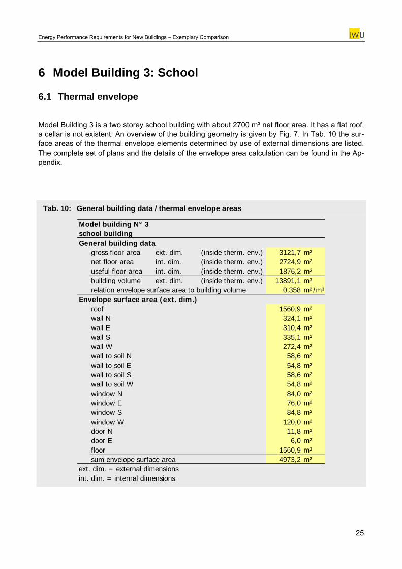
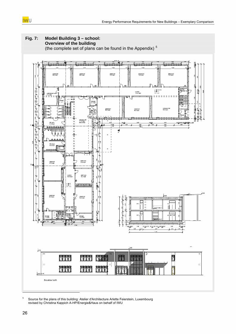
Model Building 3 is a two storey school building with about 2700 m² net floor area. It has a flat roof, a cellar is not existent. An overview of the building geometry is given by Fig. 7. In Tab. 10 the sur-face areas of the thermal envelope elements determined by use of external dimensions are listed. The complete set of plans and the details of the envelope area calculation can be found in the Ap-pendix.
Tab. 10: General building data / thermal envelope areas
Model building N° 3school buildingGeneral building data
gross floor area ext. dim. (inside therm. env.) 3121,7 m²net floor area int. dim. (inside therm. env.) 2724,9 m²useful floor area int. dim. (inside therm. env.) 1876,2 m²building volume ext. dim. (inside therm. env.) 13891,1 m³relation envelope surface area to building volume 0,358 m²/m³
Envelope surface area (ext. dim.)roof 1560,9 m²wall N 324,1 m²wall E 310,4 m²wall S 335,1 m²wall W 272,4 m²wall to soil N 58,6 m²wall to soil E 54,8 m²wall to soil S 58,6 m²wall to soil W 54,8 m²window N 84,0 m²window E 76,0 m²window S 84,8 m²window W 120,0 m²door N 11,8 m²door E 6,0 m²floor 1560,9 m²sum envelope surface area 4973,2 m²
ext. dim. = external dimensionsint. dim. = internal dimensions
25
Energy Performance Requirements for New Buildings – Exemplary Comparison
Fig. 7: Model Building 3 – school: Overview of the building (the complete set of plans can be found in the Appendix) 5
5 Source for the plans of this building: Atelier d'Architecture Arlette Feierstein, Luxembourg
revised by Christina Kappich A-HP/Energie&Haus on behalf of IWU
26
Energy Performance Requirements for New Buildings – Exemplary Comparison
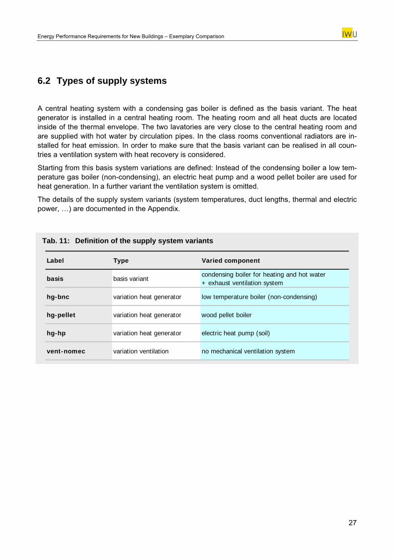
6.2 Types of supply systems
A central heating system with a condensing gas boiler is defined as the basis variant. The heat generator is installed in a central heating room. The heating room and all heat ducts are located inside of the thermal envelope. The two lavatories are very close to the central heating room and are supplied with hot water by circulation pipes. In the class rooms conventional radiators are in-stalled for heat emission. In order to make sure that the basis variant can be realised in all coun-tries a ventilation system with heat recovery is considered.
Starting from this basis system variations are defined: Instead of the condensing boiler a low tem-perature gas boiler (non-condensing), an electric heat pump and a wood pellet boiler are used for heat generation. In a further variant the ventilation system is omitted.
The details of the supply system variants (system temperatures, duct lengths, thermal and electric power, …) are documented in the Appendix.
Tab. 11: Definition of the supply system variants
Label Type Varied component
basis basis variantcondensing boiler for heating and hot water + exhaust ventilation system
hg-bnc variation heat generator low temperature boiler (non-condensing)
hg-pellet variation heat generator wood pellet boiler
hg-hp variation heat generator electric heat pump (soil)
vent-nomec variation ventilation no mechanical ventilation system
27
Energy Performance Requirements for New Buildings – Exemplary Comparison
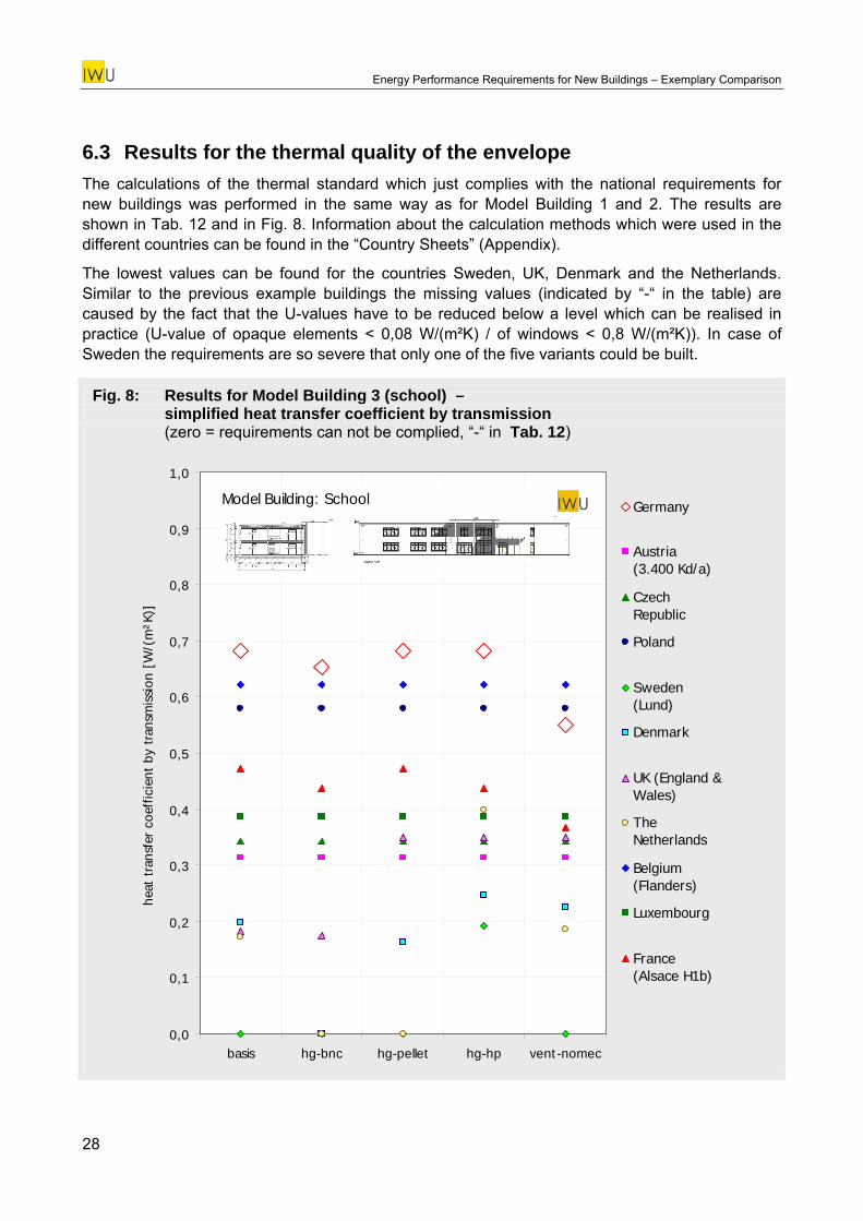
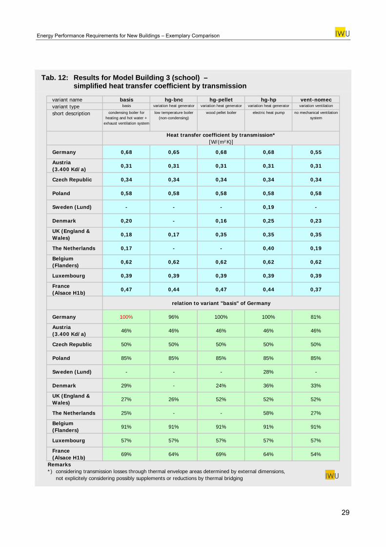
6.3 Results for the thermal quality of the envelope The calculations of the thermal standard which just complies with the national requirements for new buildings was performed in the same way as for Model Building 1 and 2. The results are shown in Tab. 12 and in Fig. 8. Information about the calculation methods which were used in the different countries can be found in the “Country Sheets” (Appendix).
The lowest values can be found for the countries Sweden, UK, Denmark and the Netherlands. Similar to the previous example buildings the missing values (indicated by “-“ in the table) are caused by the fact that the U-values have to be reduced below a level which can be realised in practice (U-value of opaque elements < 0,08 W/(m²K) / of windows < 0,8 W/(m²K)). In case of Sweden the requirements are so severe that only one of the five variants could be built.
Fig. 8: Results for Model Building 3 (school) – simplified heat transfer coefficient by transmission (zero = requirements can not be complied, “-“ in Tab. 12)
0,0
0,1
0,2
0,3
0,4
0,5
0,6
0,7
0,8
0,9
1,0
basis hg-bnc hg-pellet hg-hp vent-nomec
heat
tra
nsfe
r co
effic
ient
by
tran
smis
sion
[W
/(m
²K)]
Germany
Austria (3.400 Kd/a)
CzechRepublic
Poland
Sweden(Lund)
Denmark
UK (England &Wales)
TheNetherlands
Belgium(Flanders)
Luxembourg
France (Alsace H1b)
Model Building: School
28
Energy Performance Requirements for New Buildings – Exemplary Comparison
Tab. 12: Results for Model Building 3 (school) – simplified heat transfer coefficient by transmission
variant name basis hg-bnc hg-pellet hg-hp vent-nomecvariant type basis variation heat generator variation heat generator variation heat generator variation ventilation
short description condensing boiler for heating and hot water +
exhaust ventilation system
low temperature boiler (non-condensing)
wood pellet boiler electric heat pump no mechanical ventilation system
Heat transfer coefficient by transmission*[W/(m²K)]
Germany 0,68 0,65 0,68 0,68 0,55
Austria (3.400 Kd/a)
0,31 0,31 0,31 0,31 0,31
Czech Republic 0,34 0,34 0,34 0,34 0,34
Poland 0,58 0,58 0,58 0,58 0,58
Sweden (Lund) - - - 0,19 -
Denmark 0,20 - 0,16 0,25 0,23
UK (England & Wales)
0,18 0,17 0,35 0,35 0,35
The Netherlands 0,17 - - 0,40 0,19
Belgium (Flanders)
0,62 0,62 0,62 0,62 0,62
Luxembourg 0,39 0,39 0,39 0,39 0,39
France (Alsace H1b)
0,47 0,44 0,47 0,44 0,37
relation to variant "basis" of Germany
Germany 100% 96% 100% 100% 81%
Austria (3.400 Kd/a)
46% 46% 46% 46% 46%
Czech Republic 50% 50% 50% 50% 50%
Poland 85% 85% 85% 85% 85%
Sweden (Lund) - - - 28% -
Denmark 29% - 24% 36% 33%
UK (England & Wales)
27% 26% 52% 52% 52%
The Netherlands 25% - - 58% 27%
Belgium (Flanders)
91% 91% 91% 91% 91%
Luxembourg 57% 57% 57% 57% 57%
France (Alsace H1b)
69% 64% 69% 64% 54%
Remarks*) considering transmission losses through thermal envelope areas determined by external dimensions, not explicitely considering possibly supplements or reductions by thermal bridging
29
Energy Performance Requirements for New Buildings – Exemplary Comparison
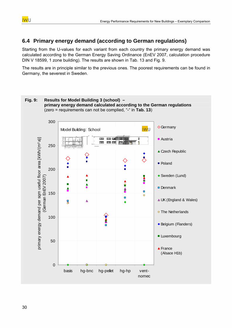
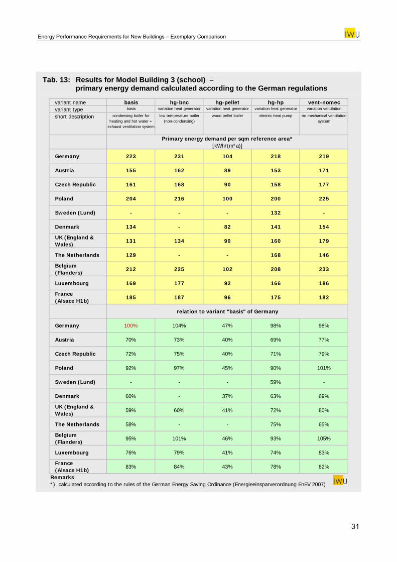
6.4 Primary energy demand (according to German regulations) Starting from the U-values for each variant from each country the primary energy demand was calculated according to the German Energy Saving Ordinance (EnEV 2007, calculation procedure DIN V 18599, 1 zone building). The results are shown in Tab. 13 and Fig. 9.
The results are in principle similar to the previous ones. The poorest requirements can be found in Germany, the severest in Sweden.
Fig. 9: Results for Model Building 3 (school) – primary energy demand calculated according to the German regulations (zero = requirements can not be complied, “-“ in Tab. 13)
0
50
100
150
200
250
300
basis hg-bnc hg-pellet hg-hp vent-nomec
prim
ary
ener
gy d
eman
d pe
r sq
m u
sefu
l flo
or a
rea
[kW
h/(m
²a)]
(G
erm
an E
nEV
2007
)
Germany
Austria
Czech Republic
Poland
Sweden (Lund)
Denmark
UK (England & Wales)
The Netherlands
Belgium (Flanders)
Luxembourg
France (Alsace H1b)
Model Building: School
30
Energy Performance Requirements for New Buildings – Exemplary Comparison
Tab. 13: Results for Model Building 3 (school) – primary energy demand calculated according to the German regulations
variant name basis hg-bnc hg-pellet hg-hp vent-nomecvariant type basis variation heat generator variation heat generator variation heat generator variation ventilation
short description condensing boiler for heating and hot water +
exhaust ventilation system
low temperature boiler (non-condensing)
wood pellet boiler electric heat pump no mechanical ventilation system
Primary energy demand per sqm reference area*[kWh/(m²a)]
Germany 223 231 104 218 219
Austria 155 162 89 153 171
Czech Republic 161 168 90 158 177
Poland 204 216 100 200 225
Sweden (Lund) - - - 132 -
Denmark 134 - 82 141 154
UK (England & Wales)
131 134 90 160 179
The Netherlands 129 - - 168 146
Belgium (Flanders)
212 225 102 208 233
Luxembourg 169 177 92 166 186
France (Alsace H1b)
185 187 96 175 182
relation to variant "basis" of Germany
Germany 100% 104% 47% 98% 98%
Austria 70% 73% 40% 69% 77%
Czech Republic 72% 75% 40% 71% 79%
Poland 92% 97% 45% 90% 101%
Sweden (Lund) - - - 59% -
Denmark 60% - 37% 63% 69%
UK (England & Wales)
59% 60% 41% 72% 80%
The Netherlands 58% - - 75% 65%
Belgium (Flanders)
95% 101% 46% 93% 105%
Luxembourg 76% 79% 41% 74% 83%
France (Alsace H1b)
83% 84% 43% 78% 82%
Remarks*) calculated according to the rules of the German Energy Saving Ordinance (Energieeinsparverordnung EnEV 2007)
31
Energy Performance Requirements for New Buildings – Exemplary Comparison
7 Résumé
The here performed investigations give an impression of the energy performance requirements of new buildings in Germany and the 10 neighboured countries Austria, Czech Republic, Poland, Sweden, Denmark, UK, Netherlands, Belgium (Flanders), Luxembourg and France. The results which are to be considered as exemplary show certain tendencies: Regarding the two residential buildings the German requirements (EnEV 2007) are settled on a more or less average level. The best energy performance is achieved by the regulations in the Netherlands, Sweden, Denmark and Luxembourg. Especially the German requirements on the thermal transmittance of the envelope turned out to be comparably poor. It is the restricting limit in cases of supply systems with high effi-ciency or biomass. In case of the school building the German energy performance level is the poorest of all considered countries - for nearly all variants. The most ambitious requirements can be found in UK, Netherlands, Sweden and Denmark.
Facing the fact that an analytic comparison of the national methods was not a subject of this study the reasons for the dependencies of the different parameters can not be explained in detail. With regard to the objective of this study – the determination of the requirement level for a considerable number of countries – the applied method proved its worth. The documented building examples show how plans and tabled descriptions can be designed in order to make possible the application of national methods by experts from different countries. From this experience a two-step approach can be recommended for future investigations: In a first step the supply system of the basis variant should be selected in co-operation with the involved partners making sure that the respective build-ing-system combination can be realised in all countries. Usually this will result in the selection of a more efficient supply system. Based on this reference case the parameter variations can be per-formed in a concerted way – omitting a variant in case that it cannot be built in a certain country.
Since primary energy demand and carbon dioxide emissions are defined differently in the national regulations (especially regarding biomass) these quantities are not adequate for a comprehensive cross-country comparison of the overall energy performance. They can only be used in a single country for illuminating comparison results by applying the national definition framework. The pri-mary energy values shown in this study can therefore be considered as translation to understand the results from the viewpoint of the German energy saving ordinance and are addressing espe-cially German experts. On an international level the simplified transfer coefficient by transmission has proved to be a good comparison criterion which gives – being a sort of average U-value – an indication of the “insulation quality” for a given building geometry and its supply system. However, the application of this method is restricted to countries with similar climates and to building types with an energy consumption that considerably depends on the thermal transmittance of the enve-lope.
32
Energy Performance Requirements for New Buildings – Exemplary Comparison
APPENDIX
Appendix 1: Definition of Model Building 1 – semi-detached single family house
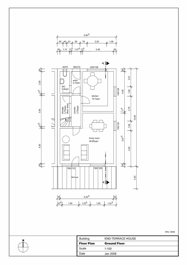
Appendix 1a: Plans
A-1
2,01
1,08
2,78
1,08
4,00
living room29,85sqm
kitchen15,7sqm
terrace
corr
idor
3,75
sqm
90/210 220/12640/51
160/126190/210
N
6,605
65 40 61 90 78 2,20 1,06
30 1,10 175 1,075 175 3,48 30
END-TERRACE HOUSE
Floor Plan Ground Floor
1:100
Date Jan 2008
Building
304,
5017
55,
675
30
10,9
52,
50
525 1,90 1,255 1,60 1,325
30 6,005 30
entry2,7sqm
302,
5017
53,
5017
54,
0030
AA
WC2,8sqm
108/
126
108/
126
stor
age
3,75
sqm
(floo
r ar
ea)
IWU 2008
NEND-TERRACE HOUSE
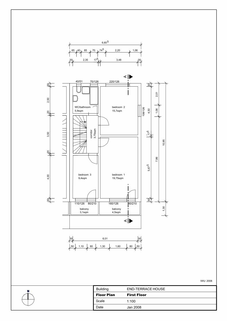
Floor Plan First Floor
1:100
Date Jan 2008
Building
2,01
1,08
7,86
bedroom 1 19,75sqm
bedroom 215,7sqm
bedroom 39,4sqm
160/126110/126 80/210
220/12670/12640/51
balcony 4,5sqm
balcony 3,1sqm
corr
idor
3,75
sqm
AA
6,605
65 40 85 70 745 2,20 1,06
30 2,35 175 3,48 30
10,9
51,
30
304,
5017
55,
675
30
30 6,01 30
50 1,10 80 1,30 1,60 80 50
302,
5020
3,50
204,
0030
80/210
WC/bathroom5,9sqm
108/
126
IWU 2008
NEND-TERRACE HOUSE
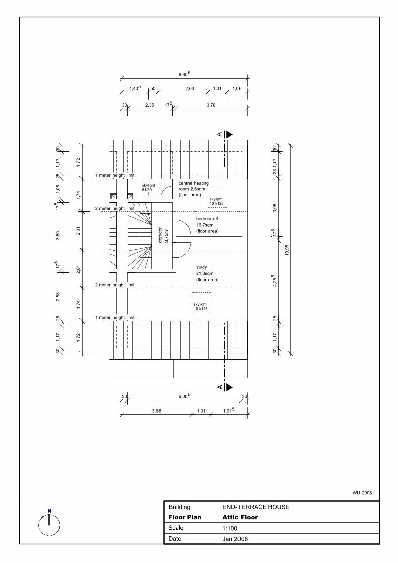
Floor Plan Attic Floor
1:100
Date Jan 2008
Building
1,405 50 2,63 1,01 1,06
study21,3sqm (floor area)
bedroom 410,7sqm (floor area)
central heating room 2,5sqm(floor area)
6,605
30 2,35 175 3,78
10,9
5
corr
idor
3,75
m²
2 meter height limit
1,72
1,74
2,01
2,01
1,74
1,72
301,
1725
1,08
175
3,50
175
2,58
251,
1730
1 meter height limit
2 meter height limit
1 meter height limit
301,
1725
3,08
175
4,25
525
1,17
30
skylight101/126
skylight101/126
skylight51/50
3,68 1,01 1,915
AA
30 6,005 30
IWU 2008
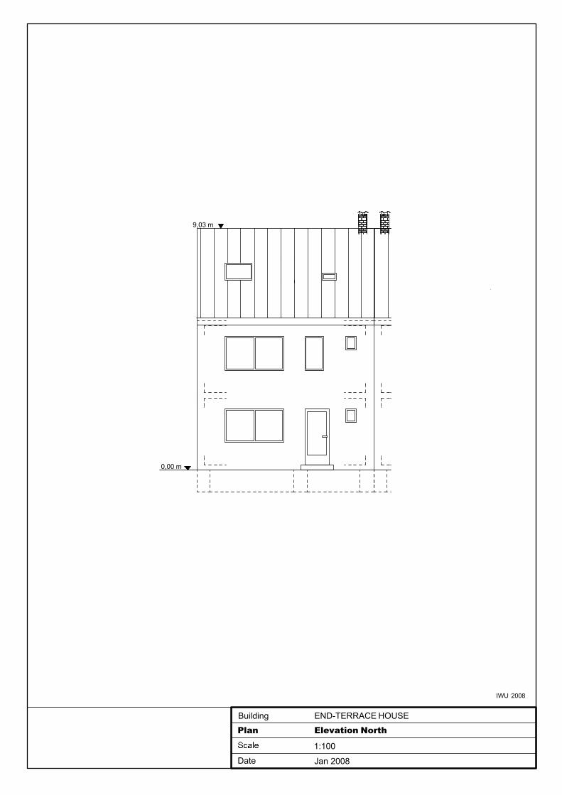
0,00 m
9,03 m
END-TERRACE HOUSE
Plan Elevation North
1:100
Date Jan 2008
Building
IWU 2008
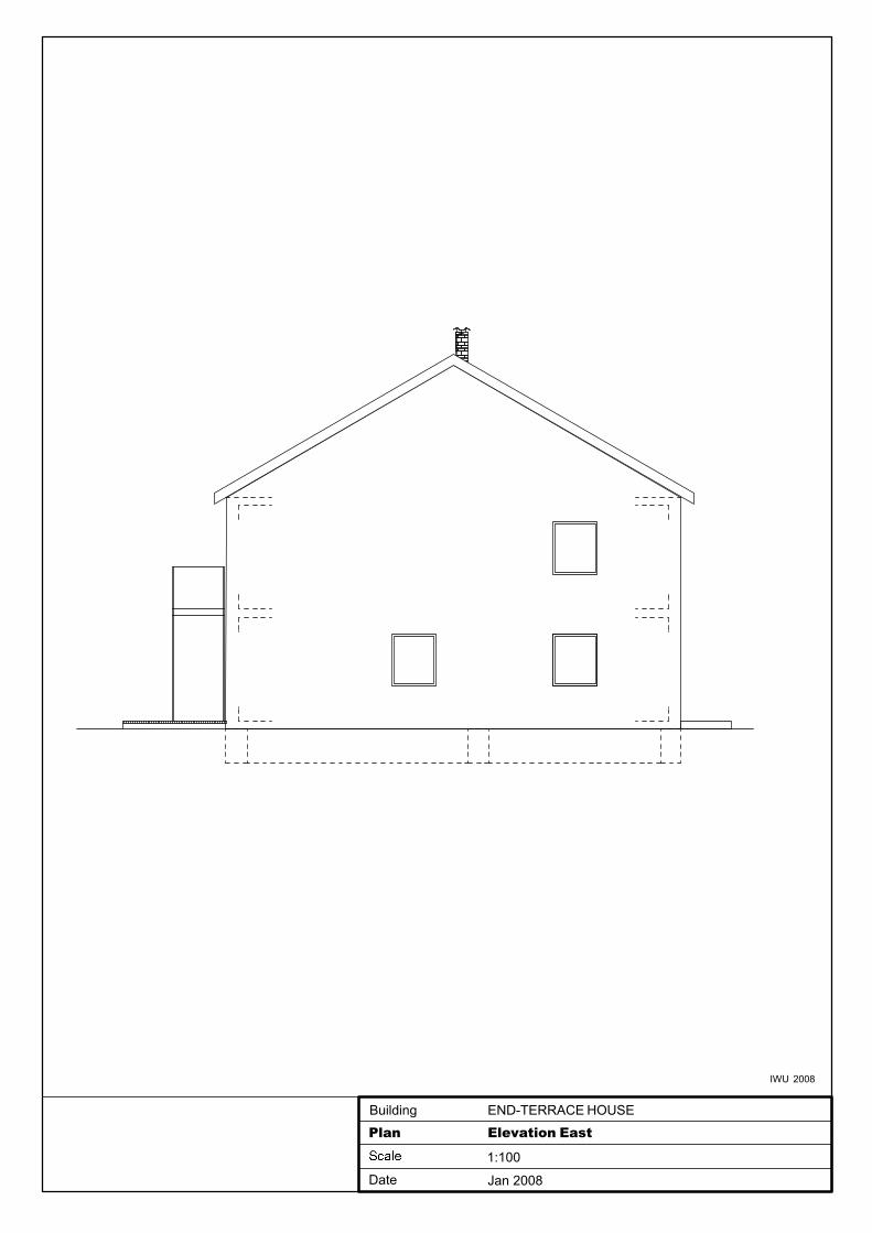
END-TERRACE HOUSE
Plan Elevation East
1:100
Date Jan 2008
Building
IWU 2008
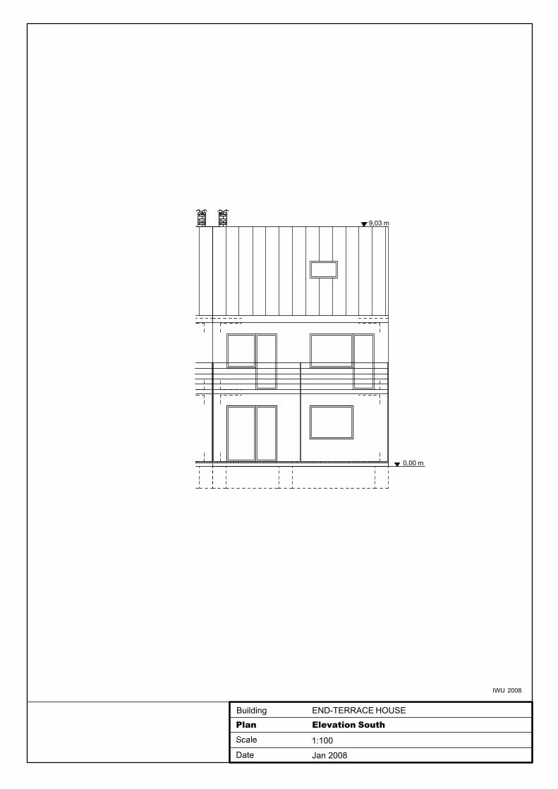
END-TERRACE HOUSE
Plan Elevation South
1:100
Date Jan 2008
Building
0,00 m
9,03 m
IWU 2008
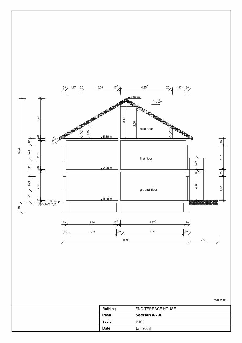
0,00 m
attic floor
first floor
ground floor
9,03 m
32°
9,03
80
601,
261,
441,
261,
04
3,43
202,
5020
2,50
20
END-TERRACE HOUSE
Plan Section A - A
1:100
Date Jan 2008
Building
10,95
50 4,14 50 5,31 50
30 4,50 175 5,675 30
1,00
30 1,17 25 3,08 175 4,255 25 1,17 30
3,17
22
2,50
2,90 m
0,20 m
5,60 m
1,00
152,
55
602,
1060
2,10
2,50
IWU 2008
Energy Performance Requirements for New Buildings – Exemplary Comparison
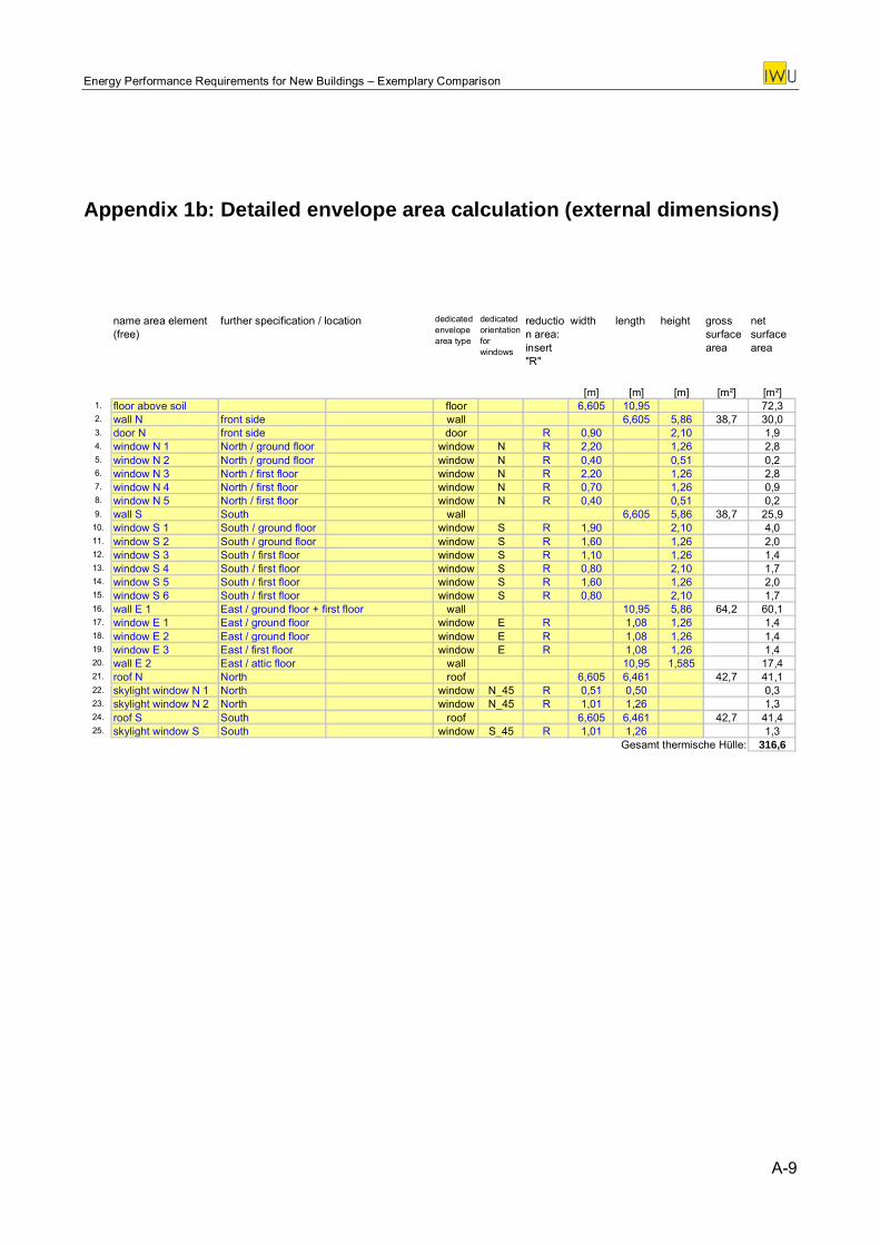
Appendix 1b: Detailed envelope area calculation (external dimensions)
name area element (free)
dedicated envelope area type
dedicated orientation for windows
reduction area: insert "R"
width length height gross surface area
net surface area
[m] [m] [m] [m²] [m²]1. floor above soil floor 6,605 10,95 72,32. wall N front side wall 6,605 5,86 38,7 30,03. door N front side door R 0,90 2,10 1,94. window N 1 North / ground floor window N R 2,20 1,26 2,85. window N 2 North / ground floor window N R 0,40 0,51 0,26. window N 3 North / first floor window N R 2,20 1,26 2,87. window N 4 North / first floor window N R 0,70 1,26 0,98. window N 5 North / first floor window N R 0,40 0,51 0,29. wall S South wall 6,605 5,86 38,7 25,9
10. window S 1 South / ground floor window S R 1,90 2,10 4,011. window S 2 South / ground floor window S R 1,60 1,26 2,012. window S 3 South / first floor window S R 1,10 1,26 1,413. window S 4 South / first floor window S R 0,80 2,10 1,714. window S 5 South / first floor window S R 1,60 1,26 2,015. window S 6 South / first floor window S R 0,80 2,10 1,716. wall E 1 East / ground floor + first floor wall 10,95 5,86 64,2 60,117. window E 1 East / ground floor window E R 1,08 1,26 1,418. window E 2 East / ground floor window E R 1,08 1,26 1,419. window E 3 East / first floor window E R 1,08 1,26 1,420. wall E 2 East / attic floor wall 10,95 1,585 17,421. roof N North roof 6,605 6,461 42,7 41,122. skylight window N 1 North window N_45 R 0,51 0,50 0,323. skylight window N 2 North window N_45 R 1,01 1,26 1,324. roof S South roof 6,605 6,461 42,7 41,425. skylight window S South window S_45 R 1,01 1,26 1,3
Gesamt thermische Hülle: 316,6
further specification / location
A-9

Energy Performance Requirements for New Buildings – Exemplary Comparison
Appendix 1c: Definition of the supply system types
Explanation of table colours:
= basic definition of the system green
= to be used only if necessary; if not compatible to the national definitions or values the most similar ones were to be used
blue
A-10

Energy Performance Requirements for New Buildings – Exemplary Comparison
Variants basis, hg-cond, hg-pellet, hg-hp, dhw-el, dhw-sol variant
variant N° 1-0 1-11 1-12 1-13 1-21 1-22
variant name basis hg-cond hg-pellet hg-hp dhw-el dhw-sol
variant type basisvariation heat
generatorvariation heat
generatorvariation heat
generatorvariation hot water
systemvariation hot water
system
short descriptionlow temperature
boilercondensing boiler wood pellet boiler electric heat pump decentral electric
thermal solar system
building
thermal envelope
envelope surface areadefinition see plans
(+ table with outside envelope areas, if appthermal bridges no relevant constructive thermal bridges
air-tightnessno blower door measurement
no blower door measurement
no blower door measurement
no blower door measurement
no blower door measurement
no blower door measurement
solar gainstotal solar energy transmittance (for radiation perpendicular to the gla 0,6external shading correction factor (all directions) 0,6
alternatively: horizon angle 30°frame area fraction of windows 0,3
heating system
heat generation (heating)
typelow temperature
boiler (not condensing)
condensing boiler
pellet boilerelectric heat
pump (soil/water)
= var. 1-0 = var. 1-0
energy carrier natural gas natural gas wood pellets electricity = var. 1-0 = var. 1-0
locationcentral heating
room (attic)= var. 1-0 = var. 1-0 = var. 1-0 = var. 1-0 = var. 1-0
control temperature
adjusted in dependence of
outdoor temperature
= var. 1-0 = var. 1-0 = var. 1-0 = var. 1-0 = var. 1-0
further specification
maximum values for supply / return temperature: 70°C
/ 55°C
= var. 1-0 = var. 1-0
maximum values for supply / return temperature: 55°C
/ 45°C
= var. 1-0 = var. 1-0
thermal power 18 kW = var. 1-0 = var. 1-0 = var. 1-0 = var. 1-0 = var. 1-0
heat distribution (heating)type water pipes = var. 1-0 = var. 1-0 = var. 1-0 = var. 1-0 = var. 1-0
location
completely inside of the thermal
envelope, vertical central string
= var. 1-0 = var. 1-0 = var. 1-0 = var. 1-0 = var. 1-0
control temperature
control of heat distribution temperature according to outdoor air temperature
= var. 1-0 = var. 1-0 = var. 1-0 = var. 1-0 = var. 1-0
electric consumption pumpelectric power = 80 W / running time = 18 h/d x 365 d/a
= var. 1-0 = var. 1-0 = var. 1-0 = var. 1-0 = var. 1-0
heating pipes (if detailed input required)
string 1main string / heating room
= var. 1-0 = var. 1-0 = var. 1-0 = var. 1-0 = var. 1-0
pipe length 2 x 2 m = var. 1-0 = var. 1-0 = var. 1-0 = var. 1-0 = var. 1-0insulation thickness 20 mm = var. 1-0 = var. 1-0 = var. 1-0 = var. 1-0 = var. 1-0alternatively: U-value 0,20 W/(m²K) = var. 1-0 = var. 1-0 = var. 1-0 = var. 1-0 = var. 1-0
string 2main string /
vertical= var. 1-0 = var. 1-0 = var. 1-0 = var. 1-0 = var. 1-0
pipe length 2 x 6 m = var. 1-0 = var. 1-0 = var. 1-0 = var. 1-0 = var. 1-0insulation thickness 20 mm = var. 1-0 = var. 1-0 = var. 1-0 = var. 1-0 = var. 1-0alternatively: U-value 0,20 W/(m²K) = var. 1-0 = var. 1-0 = var. 1-0 = var. 1-0 = var. 1-0
string 3distribution in
rooms= var. 1-0 = var. 1-0 = var. 1-0 = var. 1-0 = var. 1-0
pipe length 2 x 60 m = var. 1-0 = var. 1-0 = var. 1-0 = var. 1-0 = var. 1-0insulation thickness - = var. 1-0 = var. 1-0 = var. 1-0 = var. 1-0 = var. 1-0alternatively: U-value 0,40 W/(m²K) = var. 1-0 = var. 1-0 = var. 1-0 = var. 1-0 = var. 1-0
heat emission (heating)type radiators = var. 1-0 = var. 1-0 = var. 1-0 = var. 1-0 = var. 1-0
controlthermostatic valves (regulation range:
2K)= var. 1-0 = var. 1-0 = var. 1-0 = var. 1-0 = var. 1-0
A-11
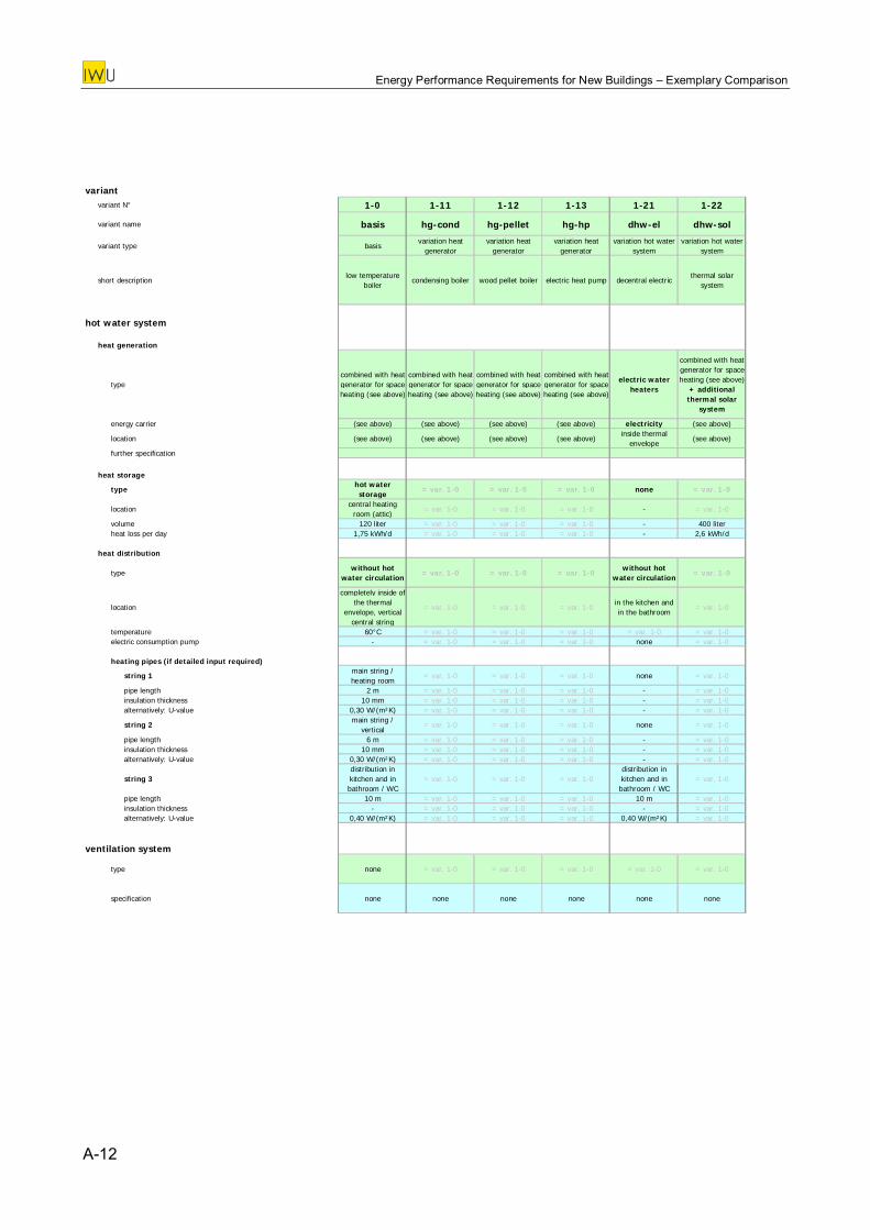
Energy Performance Requirements for New Buildings – Exemplary Comparison
variant
variant N° 1-0 1-11 1-12 1-13 1-21 1-22
variant name basis hg-cond hg-pellet hg-hp dhw-el dhw-sol
variant type basisvariation heat
generatorvariation heat
generatorvariation heat
generatorvariation hot water
systemvariation hot water
system
short descriptionlow temperature
boilercondensing boiler wood pellet boiler electric heat pump decentral electric
thermal solar system
hot water system
heat generation
typecombined with heat generator for space heating (see above)
combined with heat generator for space heating (see above)
combined with heat generator for space heating (see above)
combined with heat generator for space heating (see above)
electric water heaters
combined with heat generator for space heating (see above)
+ additional thermal solar
system
energy carrier (see above) (see above) (see above) (see above) electricity (see above)
location (see above) (see above) (see above) (see above)inside thermal
envelope(see above)
further specification
heat storage
typehot water storage
= var. 1-0 = var. 1-0 = var. 1-0 none = var. 1-0
locationcentral heating
room (attic)= var. 1-0 = var. 1-0 = var. 1-0 - = var. 1-0
volume 120 liter = var. 1-0 = var. 1-0 = var. 1-0 - 400 literheat loss per day 1,75 kWh/d = var. 1-0 = var. 1-0 = var. 1-0 - 2,6 kWh/
heat distribution
typewithout hot
water circulation= var. 1-0 = var. 1-0 = var. 1-0
without hot water circulation
= var. 1-0
location
com
d
pletely inside of the thermal
envelope, vertical central string
= var. 1-0 = var. 1-0 = var. 1-0in the kitchen and in the bathroom
= var. 1-0
temperature 60°C = var. 1-0 = var. 1-0 = var. 1-0 = var. 1-0 = var. 1-0electric consumption pump - = var. 1-0 = var. 1-0 = var. 1-0 none = var. 1-0
heating pipes (if detailed input required)
string 1main string / heating room
= var. 1-0 = var. 1-0 = var. 1-0 none = var. 1-0
pipe length 2 m = var. 1-0 = var. 1-0 = var. 1-0 - = var. 1-0insulation thickness 10 mm = var. 1-0 = var. 1-0 = var. 1-0 - = var. 1-0alternatively: U-value 0,30 W/(m²K) = var. 1-0 = var. 1-0 = var. 1-0 - = var. 1-0
string 2main string /
vertical= var. 1-0 = var. 1-0 = var. 1-0 none = var. 1-0
pipe length 6 m = var. 1-0 = var. 1-0 = var. 1-0 - = var. 1-0insulation thickness 10 mm = var. 1-0 = var. 1-0 = var. 1-0 - = var. 1-0alternatively: U-value 0,30 W/(m²K) = var. 1-0 = var. 1-0 = var. 1-0 - = var. 1-0
string 3distribution in kitchen and in bathroom / WC
= var. 1-0 = var. 1-0 = var. 1-0distribution in kitchen and in bathroom / WC
= var. 1-0
pipe length 10 m = var. 1-0 = var. 1-0 = var. 1-0 10 m = var. 1-0insulation thickness - = var. 1-0 = var. 1-0 = var. 1-0 - = var. 1-0alternatively: U-value 0,40 W/(m²K) = var. 1-0 = var. 1-0 = var. 1-0 0,40 W/(m²K) = var. 1-0
ventilation system
type none = var. 1-0 = var. 1-0 = var. 1-0 = var. 1-0 = var. 1-0
specification none none none none none none
A-12
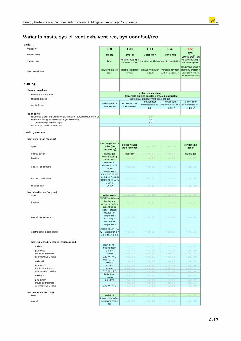
Energy Performance Requirements for New Buildings – Exemplary Comparison
Variants basis, sys-el, vent-exh, vent-rec, sys-cond/sol/rec variant
variant N° 1-0 1-31 1-41 1-42 1-51
variant name basis sys-el vent-exh vent-recsys-
cond/sol/recvariant type basis
variation heating & hot water system
variation ventilation variation ventilationvariation heating & hot water system
short descriptionlow temperature
boilerelectric resistance
systemexhaust ventilation
systemventilation system with heat recovery
condensing boiler + solar dhw system + ventilation system with heat recovery
building
thermal envelope
envelope surface areadefinition see plans
(+ table with outside envelope areas, if applicable)thermal bridges no relevant constructive thermal bridges
air-tightnessno blower door measurement
no blower door measurement
blower door measurement: n50
< 5 h-1
blower door measurement: n50
< 5 h-1
blower door measurement: n50
<1, 1, 1,5 h-1
solar gainstotal solar energy transmittance (for radiation perpendicular to the gla 0,6external shading correction factor (all directions) 0,6
alternatively: horizon angle 30°frame area fraction of windows 0,3
heating system
heat generation (heating)
typelow temperature
boiler (not condensing)
eletric heated water storage
= var. 1-0 = var. 1-0condensing
boiler
energy carrier natural gas electricity = var. 1-0 = var. 1-0 natural gas
locationcentral heating
room (attic)= var. 1-0 = var. 1-0 = var. 1-0 = var. 1-0
control temperature
adjusted in dependence of
outdoor temperature
= var. 1-0 = var. 1-0 = var. 1-0 = var. 1-0
further specification
maximum values for supply / return temperature: 70°C
/ 55°C
= var. 1-0 = var. 1-0 = var. 1-0 = var. 1-0
thermal power 18 kW = var. 1-0 = var. 1-0 = var. 1-0 = var. 1-0
heat distribution (heating)type water pipes = var. 1-0 = var. 1-0 = var. 1-0 = var. 1-0
location
completely inside of the thermal
envelope, vertical central string
= var. 1-0 = var. 1-0 = var. 1-0 = var. 1-0
control temperature
control of heat distribution temperature according to outdoor air temperature
= var. 1-0 = var. 1-0 = var. 1-0 = var. 1-0
electric consumption pumpelectric power = 80 W / running time = 18 h/d x 365 d/a
= var. 1-0 = var. 1-0 = var. 1-0 = var. 1-0
heating pipes (if detailed input required)
string 1main string / heating room
= var. 1-0 = var. 1-0 = var. 1-0 = var. 1-0
pipe length 2 x 2 m = var. 1-0 = var. 1-0 = var. 1-0 = var. 1-0insulation thickness 20 mm = var. 1-0 = var. 1-0 = var. 1-0 = var. 1-0alternatively: U-value 0,20 W/(m²K) = var. 1-0 = var. 1-0 = var. 1-0 = var. 1-0
string 2main string /
vertical= var. 1-0 = var. 1-0 = var. 1-0 = var. 1-0
pipe length 2 x 6 m = var. 1-0 = var. 1-0 = var. 1-0 = var. 1-0insulation thickness 20 mm = var. 1-0 = var. 1-0 = var. 1-0 = var. 1-0alternatively: U-value 0,20 W/(m²K) = var. 1-0 = var. 1-0 = var. 1-0 = var. 1-0
string 3distribution in
rooms= var. 1-0 = var. 1-0 = var. 1-0 = var. 1-0
pipe length 2 x 60 m = var. 1-0 = var. 1-0 = var. 1-0 = var. 1-0insulation thickness - = var. 1-0 = var. 1-0 = var. 1-0 = var. 1-0alternatively: U-value 0,40 W/(m²K) = var. 1-0 = var. 1-0 = var. 1-0 = var. 1-0
heat emission (heating)type radiators = var. 1-0 = var. 1-0 = var. 1-0 = var. 1-0
controlthermostatic valves (regulation range:
2K= var. 1-0 = var. 1-0 = var. 1-0 = var. 1-0
)
A-13
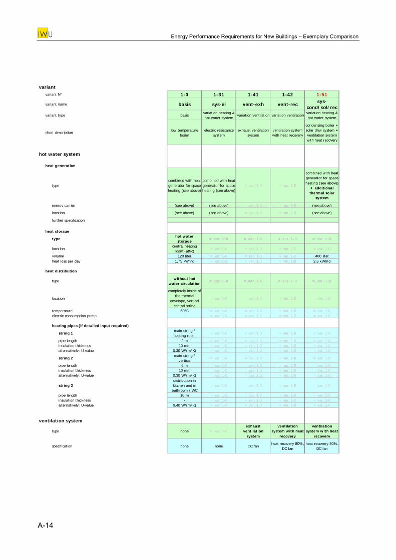
Energy Performance Requirements for New Buildings – Exemplary Comparison
variant
variant N° 1-0 1-31 1-41 1-42 1-51
variant name basis sys-el vent-exh vent-recsys-
cond/sol/rec
variant type basisvariation heating & hot water system
variation ventilation variation ventilationvariation heating & hot water system
short descriptionlow temperature
boilerelectric resistance
systemexhaust ventilation
systemventilation system with heat recovery
condensing boiler + solar dhw system + ventilation system with heat recovery
hot water system
heat generation
typecombined with heat generator for space heating (see above)
combined with heat generator for space heating (see above)
= var. 1-0 = var. 1-0
combined with heat generator for space heating (see above)
+ additional thermal solar
system
energy carrier (see above) (see above) = var. 1-0 = var. 1-0 (see above)
location (see above) (see above) = var. 1-0 = var. 1-0 (see above)
further specification
heat storage
typehot water storage
= var. 1-0 = var. 1-0 = var. 1-0 = var. 1-0
locationcentral heating
room (attic)= var. 1-0 = var. 1-0 = var. 1-0 = var. 1-0
volume 120 liter = var. 1-0 = var. 1-0 = var. 1-0 400 literheat loss per day 1,75 kWh/d = var. 1-0 = var. 1-0 = var. 1-0 2,6 kWh/d
heat distribution
typewithout hot
water circulation= var. 1-0 = var. 1-0 = var. 1-0 = var. 1-0
location
completely inside of the thermal
envelope, vertical central string
= var. 1-0 = var. 1-0 = var. 1-0 = var. 1-0
temperature 60°C = var. 1-0 = var. 1-0 = var. 1-0 = var. 1-0electric consumption pump - = var. 1-0 = var. 1-0 = var. 1-0 = var. 1-0
heating pipes (if detailed input required)
string 1main string / heating room
= var. 1-0 = var. 1-0 = var. 1-0 = var. 1-0
pipe length 2 m = var. 1-0 = var. 1-0 = var. 1-0 = var. 1-0insulation thickness 10 mm = var. 1-0 = var. 1-0 = var. 1-0 = var. 1-0alternatively: U-value 0,30 W/(m²K) = var. 1-0 = var. 1-0 = var. 1-0 = var. 1-0
string 2main string /
vertical= var. 1-0 = var. 1-0 = var. 1-0 = var. 1-0
pipe length 6 m = var. 1-0 = var. 1-0 = var. 1-0 = var. 1-0insulation thickness 10 mm = var. 1-0 = var. 1-0 = var. 1-0 = var. 1-0alternatively: U-value 0,30 W/(m²K) = var. 1-0 = var. 1-0 = var. 1-0 = var. 1-0
string 3distribution in kitchen and in bathroom / WC
= var. 1-0 = var. 1-0 = var. 1-0 = var. 1-0
pipe length 10 m = var. 1-0 = var. 1-0 = var. 1-0 = var. 1-0insulation thickness - = var. 1-0 = var. 1-0 = var. 1-0 = var. 1-0alternatively: U-value 0,40 W/(m²K) = var. 1-0 = var. 1-0 = var. 1-0 = var. 1-0
ventilation system
type none = var. 1-0exhaust
ventilation s stem
ventilation system with heat
recover
ventilation system with heat
recovery y y
specification none none DC fanheat recovery 80%,
DC fanheat recovery 80%,
DC fan
A-14

Energy Performance Requirements for New Buildings – Exemplary Comparison
Appendix 1d: Country sheets
A-15
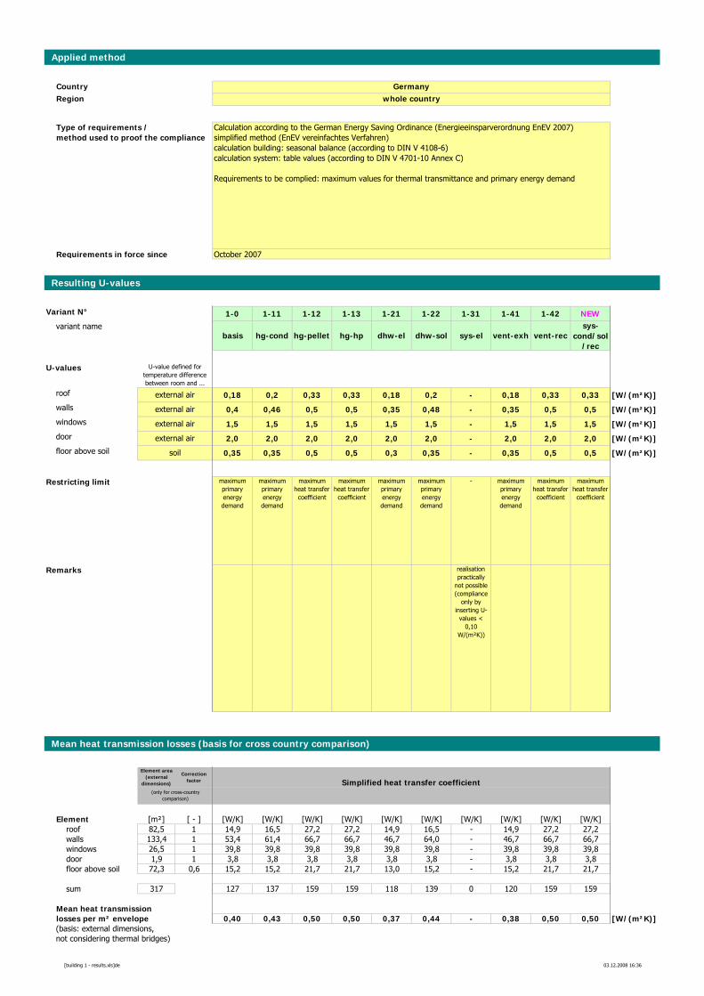
Applied method
CountryRegion
Requirements in force since
Resulting U-values
Variant N° 1-0 1-11 1-12 1-13 1-21 1-22 1-31 1-41 1-42 NEWvariant name
basis hg-cond hg-pellet hg-hp dhw-el dhw-sol sys-el vent-exh vent-recsys-
cond/sol/rec
U-values
roof 0,18 0,2 0,33 0,33 0,18 0,2 - 0,18 0,33 0,33 [W/(m²K)]walls 0,4 0,46 0,5 0,5 0,35 0,48 - 0,35 0,5 0,5 [W/(m²K)]windows 1,5 1,5 1,5 1,5 1,5 1,5 - 1,5 1,5 1,5 [W/(m²K)]door 2,0 2,0 2,0 2,0 2,0 2,0 - 2,0 2,0 2,0 [W/(m²K)]floor above soil 0,35 0,35 0,5 0,5 0,3 0,35 - 0,35 0,5 0,5 [W/(m²K)]
Restricting limit maximum primary energy demand
maximum primary energy demand
maximum heat transfer
coefficient
maximum heat transfer
coefficient
maximum primary energy demand
maximum primary energy demand
- maximum primary energy demand
maximum heat transfer
coefficient
maximum heat transfer
coefficient
Remarks realisation practically
not possible (compliance
only by inserting U-
values < 0,10
W/(m²K))
Mean heat transmission losses (basis for cross country comparison)
Element area (external
dimensions)
Correction factor Simplified heat transfer coefficient
Element [m²] [ - ] [W/K] [W/K] [W/K] [W/K] [W/K] [W/K] [W/K] [W/K] [W/K] [W/K]roof 82,5 1 14,9 16,5 27,2 27,2 14,9 16,5 - 14,9 27,2 27,2walls 133,4 1 53,4 61,4 66,7 66,7 46,7 64,0 - 46,7 66,7 66,7windows 26,5 1 39,8 39,8 39,8 39,8 39,8 39,8 - 39,8 39,8 39,8door 1,9 1 3,8 3,8 3,8 3,8 3,8 3,8 - 3,8 3,8 3,8floor above soil 72,3 0,6 15,2 15,2 21,7 21,7 13,0 15,2 - 15,2 21,7 21,7
sum 317 127 137 159 159 118 139 0 120 159 159
Mean heat transmissionlosses per m² envelope 0,40 0,43 0,50 0,50 0,37 0,44 - 0,38 0,50 0,50 [W/(m²K)](basis: external dimensions,not considering thermal bridges)
(only for cross-country comparison)
soil
external air
external air
external air
external air
Calculation according to the German Energy Saving Ordinance (Energieeinsparverordnung EnEV 2007)simplified method (EnEV vereinfachtes Verfahren)calculation building: seasonal balance (according to DIN V 4108-6)calculation system: table values (according to DIN V 4701-10 Annex C)
Requirements to be complied: maximum values for thermal transmittance and primary energy demand
Germanywhole country
U-value defined for temperature difference between room and ...
October 2007
Type of requirements / method used to proof the compliance
[building 1 - results.xls]de 03.12.2008 16:36
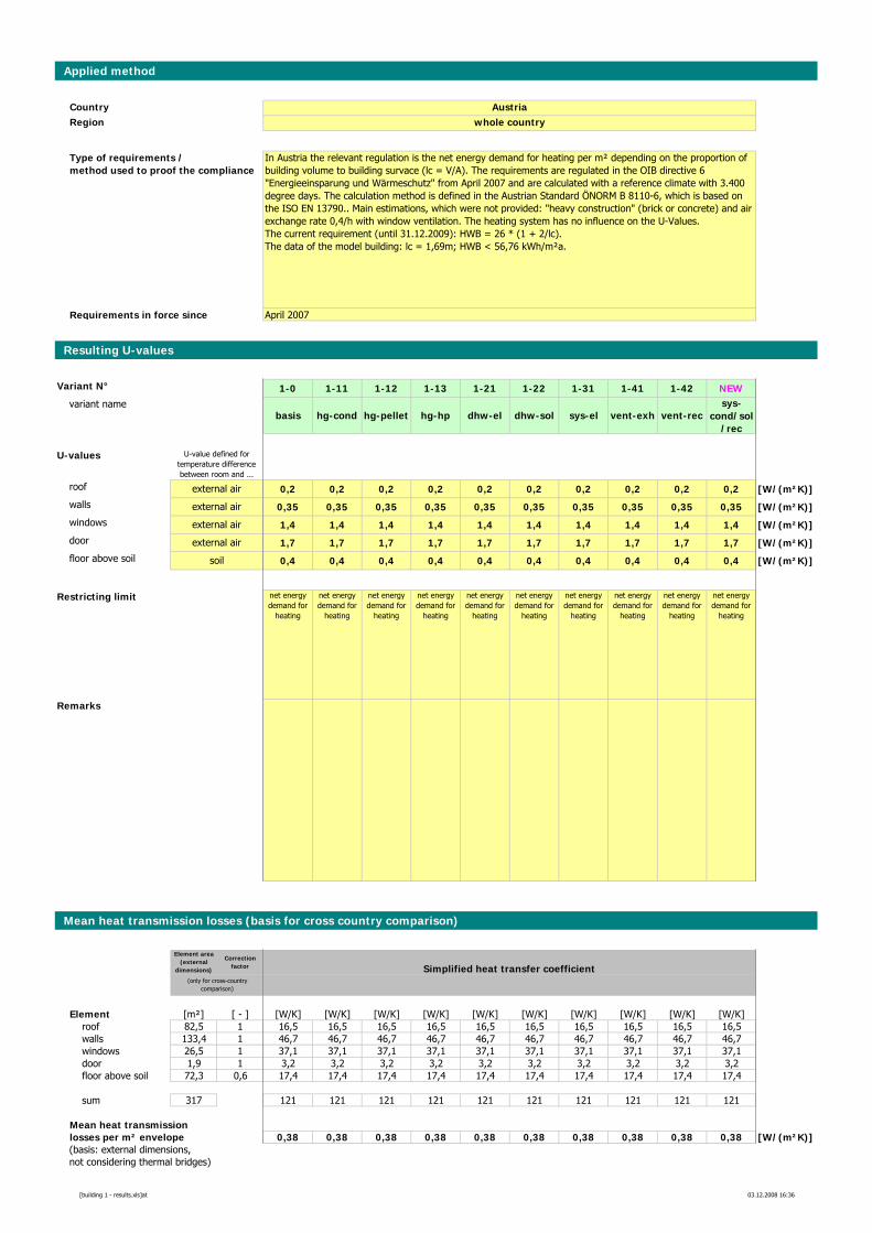
Applied method
CountryRegion
Requirements in force since
Resulting U-values
Variant N° 1-0 1-11 1-12 1-13 1-21 1-22 1-31 1-41 1-42 NEWvariant name
basis hg-cond hg-pellet hg-hp dhw-el dhw-sol sys-el vent-exh vent-recsys-
cond/sol/rec
U-values
roof 0,2 0,2 0,2 0,2 0,2 0,2 0,2 0,2 0,2 0,2 [W/(m²K)]walls 0,35 0,35 0,35 0,35 0,35 0,35 0,35 0,35 0,35 0,35 [W/(m²K)]windows 1,4 1,4 1,4 1,4 1,4 1,4 1,4 1,4 1,4 1,4 [W/(m²K)]door 1,7 1,7 1,7 1,7 1,7 1,7 1,7 1,7 1,7 1,7 [W/(m²K)]floor above soil 0,4 0,4 0,4 0,4 0,4 0,4 0,4 0,4 0,4 0,4 [W/(m²K)]
Restricting limit net energy demand for
heating
net energy demand for
heating
net energy demand for
heating
net energy demand for
heating
net energy demand for
heating
net energy demand for
heating
net energy demand for
heating
net energy demand for
heating
net energy demand for
heating
net energy demand for
heating
Remarks
Mean heat transmission losses (basis for cross country comparison)
Element area (external
dimensions)
Correction factor Simplified heat transfer coefficient
Element [m²] [ - ] [W/K] [W/K] [W/K] [W/K] [W/K] [W/K] [W/K] [W/K] [W/K] [W/K]roof 82,5 1 16,5 16,5 16,5 16,5 16,5 16,5 16,5 16,5 16,5 16,5walls 133,4 1 46,7 46,7 46,7 46,7 46,7 46,7 46,7 46,7 46,7 46,7windows 26,5 1 37,1 37,1 37,1 37,1 37,1 37,1 37,1 37,1 37,1 37,1door 1,9 1 3,2 3,2 3,2 3,2 3,2 3,2 3,2 3,2 3,2 3,2floor above soil 72,3 0,6 17,4 17,4 17,4 17,4 17,4 17,4 17,4 17,4 17,4 17,4
sum 317 121 121 121 121 121 121 121 121 121 121
Mean heat transmissionlosses per m² envelope 0,38 0,38 0,38 0,38 0,38 0,38 0,38 0,38 0,38 0,38 [W/(m²K)](basis: external dimensions,not considering thermal bridges)
(only for cross-country comparison)
In Austria the relevant regulation is the net energy demand for heating per m² depending on the proportion of building volume to building survace (lc = V/A). The requirements are regulated in the OIB directive 6 "Energieeinsparung und Wärmeschutz" from April 2007 and are calculated with a reference climate with 3.400 degree days. The calculation method is defined in the Austrian Standard ÖNORM B 8110-6, which is based on the ISO EN 13790.. Main estimations, which were not provided: "heavy construction" (brick or concrete) and air exchange rate 0,4/h with window ventilation. The heating system has no influence on the U-Values.The current requirement (until 31.12.2009): HWB = 26 * (1 + 2/lc). The data of the model building: lc = 1,69m; HWB < 56,76 kWh/m²a.
Austriawhole country
U-value defined for temperature difference between room and ...
soil
external air
external air
external air
external air
April 2007
Type of requirements / method used to proof the compliance
[building 1 - results.xls]at 03.12.2008 16:36
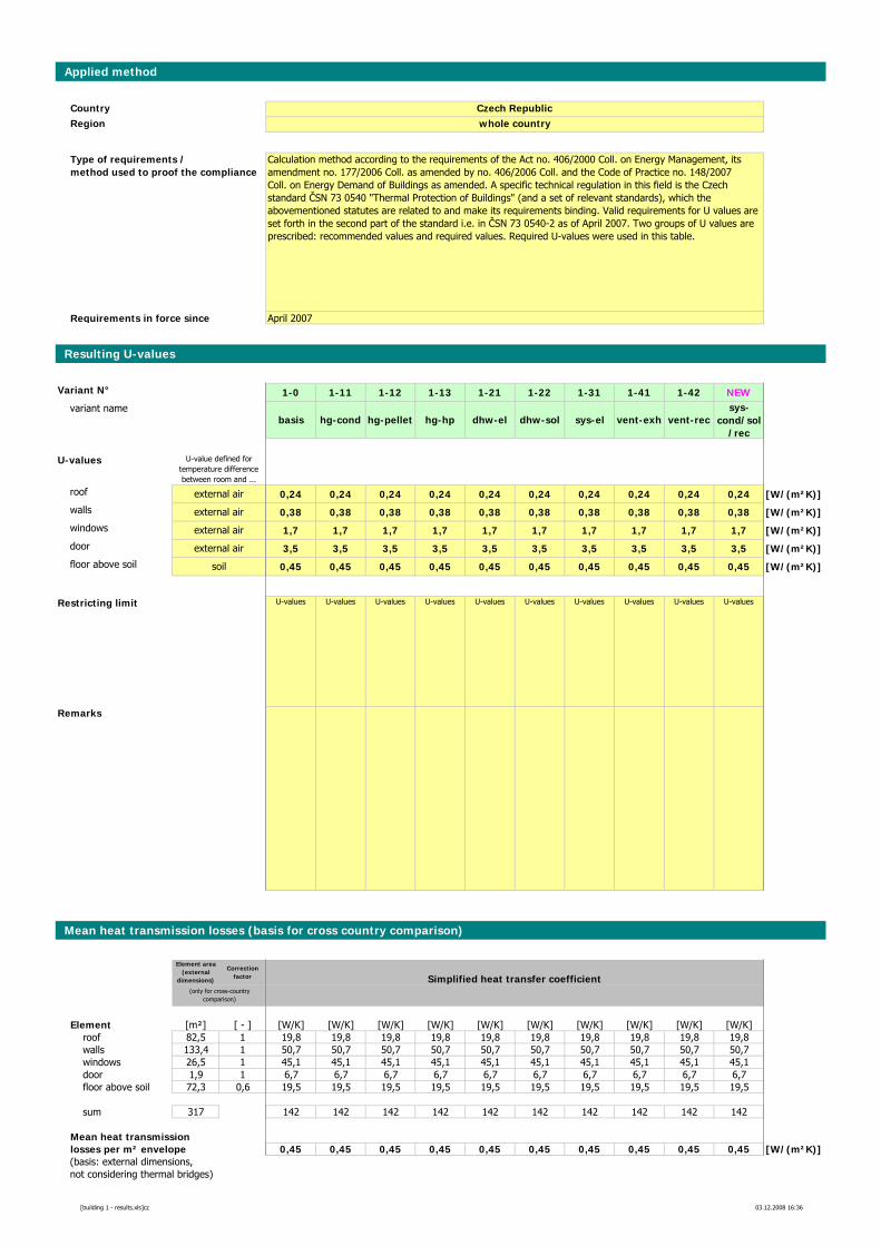
Applied method
CountryRegion
Requirements in force since
Resulting U-values
Variant N° 1-0 1-11 1-12 1-13 1-21 1-22 1-31 1-41 1-42 NEWvariant name
basis hg-cond hg-pellet hg-hp dhw-el dhw-sol sys-el vent-exh vent-recsys-
cond/sol/rec
U-values
roof 0,24 0,24 0,24 0,24 0,24 0,24 0,24 0,24 0,24 0,24 [W/(m²K)]walls 0,38 0,38 0,38 0,38 0,38 0,38 0,38 0,38 0,38 0,38 [W/(m²K)]windows 1,7 1,7 1,7 1,7 1,7 1,7 1,7 1,7 1,7 1,7 [W/(m²K)]door 3,5 3,5 3,5 3,5 3,5 3,5 3,5 3,5 3,5 3,5 [W/(m²K)]floor above soil 0,45 0,45 0,45 0,45 0,45 0,45 0,45 0,45 0,45 0,45 [W/(m²K)]
Restricting limit U-values U-values U-values U-values U-values U-values U-values U-values U-values U-values
Remarks
Mean heat transmission losses (basis for cross country comparison)
Element area (external
dimensions)
Correction factor Simplified heat transfer coefficient
Element [m²] [ - ] [W/K] [W/K] [W/K] [W/K] [W/K] [W/K] [W/K] [W/K] [W/K] [W/K]roof 82,5 1 19,8 19,8 19,8 19,8 19,8 19,8 19,8 19,8 19,8 19,8walls 133,4 1 50,7 50,7 50,7 50,7 50,7 50,7 50,7 50,7 50,7 50,7windows 26,5 1 45,1 45,1 45,1 45,1 45,1 45,1 45,1 45,1 45,1 45,1door 1,9 1 6,7 6,7 6,7 6,7 6,7 6,7 6,7 6,7 6,7 6,7floor above soil 72,3 0,6 19,5 19,5 19,5 19,5 19,5 19,5 19,5 19,5 19,5 19,5
sum 317 142 142 142 142 142 142 142 142 142 142
Mean heat transmissionlosses per m² envelope 0,45 0,45 0,45 0,45 0,45 0,45 0,45 0,45 0,45 0,45 [W/(m²K)](basis: external dimensions,not considering thermal bridges)
(only for cross-country comparison)
Calculation method according to the requirements of the Act no. 406/2000 Coll. on Energy Management, its amendment no. 177/2006 Coll. as amended by no. 406/2006 Coll. and the Code of Practice no. 148/2007Coll. on Energy Demand of Buildings as amended. A specific technical regulation in this field is the Czech standard ČSN 73 0540 "Thermal Protection of Buildings" (and a set of relevant standards), which the abovementioned statutes are related to and make its requirements binding. Valid requirements for U values are set forth in the second part of the standard i.e. in ČSN 73 0540-2 as of April 2007. Two groups of U values are prescribed: recommended values and required values. Required U-values were used in this table.
Czech Republicwhole country
U-value defined for temperature difference between room and ...
soil
external air
external air
external air
external air
April 2007
Type of requirements / method used to proof the compliance
[building 1 - results.xls]cz 03.12.2008 16:36
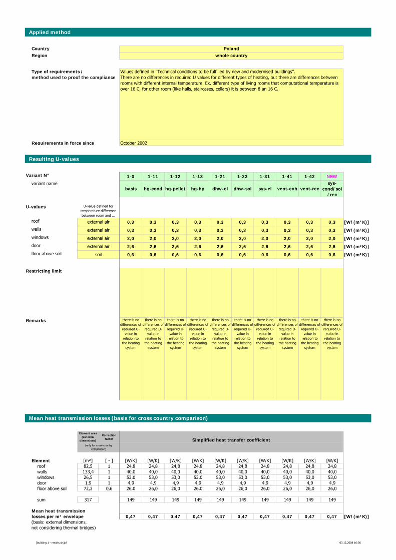
Applied method
CountryRegion
Requirements in force since
Resulting U-values
Variant N° 1-0 1-11 1-12 1-13 1-21 1-22 1-31 1-41 1-42 NEWvariant name
basis hg-cond hg-pellet hg-hp dhw-el dhw-sol sys-el vent-exh vent-recsys-
cond/sol/rec
U-values
roof 0,3 0,3 0,3 0,3 0,3 0,3 0,3 0,3 0,3 0,3 [W/(m²K)]walls 0,3 0,3 0,3 0,3 0,3 0,3 0,3 0,3 0,3 0,3 [W/(m²K)]windows 2,0 2,0 2,0 2,0 2,0 2,0 2,0 2,0 2,0 2,0 [W/(m²K)]door 2,6 2,6 2,6 2,6 2,6 2,6 2,6 2,6 2,6 2,6 [W/(m²K)]floor above soil 0,6 0,6 0,6 0,6 0,6 0,6 0,6 0,6 0,6 0,6 [W/(m²K)]
Restricting limit
Remarks there is no differences of required U-
value in relation to the heating
system
there is no differences of required U-
value in relation to the heating
system
there is no differences of required U-
value in relation to the heating
system
there is no differences of required U-
value in relation to the heating
system
there is no differences of required U-
value in relation to the heating
system
there is no differences of required U-
value in relation to the heating
system
there is no differences of required U-
value in relation to the heating
system
there is no differences of required U-
value in relation to the heating
system
there is no differences of required U-
value in relation to the heating
system
there is no differences of required U-
value in relation to the heating
system
Mean heat transmission losses (basis for cross country comparison)
Element area (external
dimensions)
Correction factor Simplified heat transfer coefficient
Element [m²] [ - ] [W/K] [W/K] [W/K] [W/K] [W/K] [W/K] [W/K] [W/K] [W/K] [W/K]roof 82,5 1 24,8 24,8 24,8 24,8 24,8 24,8 24,8 24,8 24,8 24,8walls 133,4 1 40,0 40,0 40,0 40,0 40,0 40,0 40,0 40,0 40,0 40,0windows 26,5 1 53,0 53,0 53,0 53,0 53,0 53,0 53,0 53,0 53,0 53,0door 1,9 1 4,9 4,9 4,9 4,9 4,9 4,9 4,9 4,9 4,9 4,9floor above soil 72,3 0,6 26,0 26,0 26,0 26,0 26,0 26,0 26,0 26,0 26,0 26,0
sum 317 149 149 149 149 149 149 149 149 149 149
Mean heat transmissionlosses per m² envelope 0,47 0,47 0,47 0,47 0,47 0,47 0,47 0,47 0,47 0,47 [W/(m²K)](basis: external dimensions,not considering thermal bridges)
(only for cross-country comparison)
Values defined in "Technical conditions to be fulfilled by new and modernised buildings”. There are no differences in required U values for different types of heating, but there are differences between rooms with different internal temperature. Ex. different type of living rooms that computational temperature is over 16 C, for other room (like halls, staircases, cellars) it is between 8 an 16 C.
Polandwhole country
U-value defined for temperature difference between room and ...
soil
external air
external air
external air
external air
October 2002
Type of requirements / method used to proof the compliance
[building 1 - results.xls]pl 03.12.2008 16:36
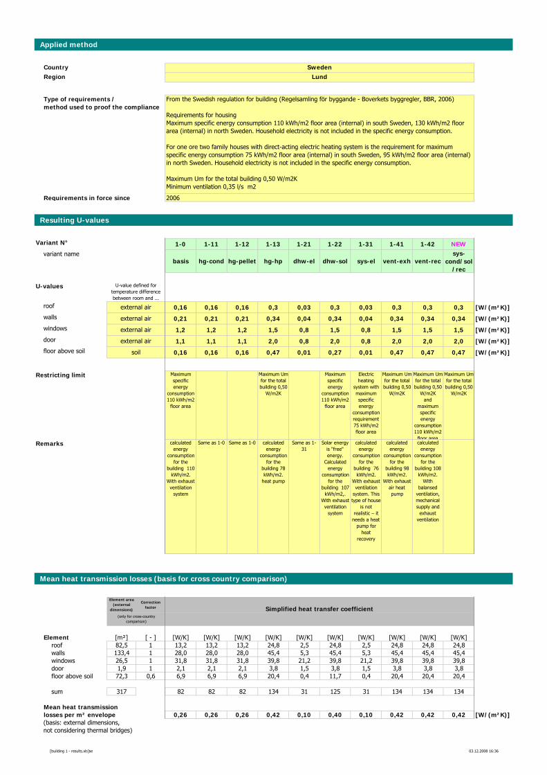
Applied method
CountryRegion
Requirements in force since
Resulting U-values
Variant N° 1-0 1-11 1-12 1-13 1-21 1-22 1-31 1-41 1-42 NEWvariant name
basis hg-cond hg-pellet hg-hp dhw-el dhw-sol sys-el vent-exh vent-recsys-
cond/sol/rec
U-values
roof 0,16 0,16 0,16 0,3 0,03 0,3 0,03 0,3 0,3 0,3 [W/(m²K)]walls 0,21 0,21 0,21 0,34 0,04 0,34 0,04 0,34 0,34 0,34 [W/(m²K)]windows 1,2 1,2 1,2 1,5 0,8 1,5 0,8 1,5 1,5 1,5 [W/(m²K)]door 1,1 1,1 1,1 2,0 0,8 2,0 0,8 2,0 2,0 2,0 [W/(m²K)]floor above soil 0,16 0,16 0,16 0,47 0,01 0,27 0,01 0,47 0,47 0,47 [W/(m²K)]
Restricting limit Maximum specific energy
consumption 110 kWh/m2
floor area
Maximum Um for the total building 0,50
W/m2K
Maximum specific energy
consumption 110 kWh/m2
floor area
Electric heating
system with maximum specific energy
consumption requirement75 kWh/m2 floor area
Maximum Um for the total building 0,50
W/m2K
Maximum Um for the total building 0,50
W/m2K and
maximum specific energy
consumption 110 kWh/m2
floor area
Maximum Um for the total building 0,50
W/m2K
Remarks calculated energy
consumption for the
building 110 kWh/m2.
With exhaust ventilation
system
Same as 1-0 Same as 1-0 calculated energy
consumption for the
building 78 kWh/m2.
heat pump
Same as 1-31
Solar energy is "free" energy.
Calculated energy
consumption for the
building 107 kWh/m2,.
With exhaust ventilation
system
calculated energy
consumption for the
building 76 kWh/m2.
With exhaust ventilation
system. This type of house
is not realistic – it
needs a heat pump for
heat recovery
calculated energy
consumption for the
building 98 kWh/m2.
With exhaust air heat pump
calculated energy
consumption for the
building 108 kWh/m2.
With balansed
ventilation, mechanical supply and
exhaust ventilation
Mean heat transmission losses (basis for cross country comparison)
Element area (external
dimensions)
Correction factor Simplified heat transfer coefficient
Element [m²] [ - ] [W/K] [W/K] [W/K] [W/K] [W/K] [W/K] [W/K] [W/K] [W/K] [W/K]roof 82,5 1 13,2 13,2 13,2 24,8 2,5 24,8 2,5 24,8 24,8 24,8walls 133,4 1 28,0 28,0 28,0 45,4 5,3 45,4 5,3 45,4 45,4 45,4windows 26,5 1 31,8 31,8 31,8 39,8 21,2 39,8 21,2 39,8 39,8 39,8door 1,9 1 2,1 2,1 2,1 3,8 1,5 3,8 1,5 3,8 3,8 3,8floor above soil 72,3 0,6 6,9 6,9 6,9 20,4 0,4 11,7 0,4 20,4 20,4 20,4
sum 317 82 82 82 134 31 125 31 134 134 134
Mean heat transmissionlosses per m² envelope 0,26 0,26 0,26 0,42 0,10 0,40 0,10 0,42 0,42 0,42 [W/(m²K)](basis: external dimensions,not considering thermal bridges)
(only for cross-country comparison)
soil
external air
external air
external air
external air
From the Swedish regulation for building (Regelsamling för byggande - Boverkets byggregler, BBR, 2006)
Requirements for housing Maximum specific energy consumption 110 kWh/m2 floor area (internal) in south Sweden, 130 kWh/m2 floor area (internal) in north Sweden. Household electricity is not included in the specific energy consumption.
For one ore two family houses with direct-acting electric heating system is the requirement for maximum specific energy consumption 75 kWh/m2 floor area (internal) in south Sweden, 95 kWh/m2 floor area (internal) in north Sweden. Household electricity is not included in the specific energy consumption.
Maximum Um for the total building 0,50 W/m2KMinimum ventilation 0,35 l/s m2
SwedenLund
U-value defined for temperature difference between room and ...
2006
Type of requirements / method used to proof the compliance
[building 1 - results.xls]se 03.12.2008 16:36
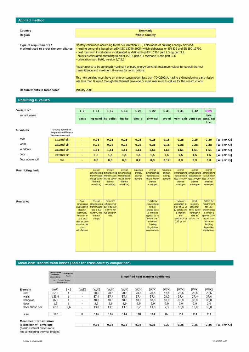
Applied method
CountryRegion
Requirements in force since
Resulting U-values
Variant N° 1-0 1-11 1-12 1-13 1-21 1-22 1-31 1-41 1-42 NEWvariant name
basis hg-cond hg-pellet hg-hp dhw-el dhw-sol sys-el vent-exh vent-recsys-
cond/sol/rec
U-values
roof - 0,25 0,25 0,25 0,25 0,25 0,15 0,25 0,25 0,25 [W/(m²K)]walls - 0,28 0,28 0,28 0,28 0,28 0,18 0,28 0,28 0,28 [W/(m²K)]windows - 1,51 1,51 1,51 1,51 1,51 1,51 1,51 1,51 1,51 [W/(m²K)]door - 1,5 1,5 1,5 1,5 1,5 1,5 1,5 1,5 1,5 [W/(m²K)]floor above soil - 0,3 0,3 0,3 0,2 0,3 0,17 0,3 0,3 0,3 [W/(m²K)]
Restricting limit - overall dimensioning transmission loss (8 W/m²
thermal envelope)
overall dimensioning transmission loss (8 W/m²
thermal envelope)
overall dimensioning transmission loss (8 W/m²
thermal envelope)
maximum primary energy demand
overall dimensioning transmission loss (8 W/m²
thermal envelope)
maximum primary energy demand
overall dimensioning transmission loss (8 W/m²
thermal envelope)
overall dimensioning transmission loss (8 W/m²
thermal envelope)
overall dimensioning transmission loss (8 W/m²
thermal envelope)
Remarks Non-condensing gas boiler is
illegal in Denmark,
variation 1-11 is thus
used as base case for the
other calculations.
Overall dimensioning transmission loss ≤ 8.0
W/m²K, incl. thermal bridges
Estimated efficiency of pellet burner is 80 % for full and part
load.
Fulfills the requirement
for Low Energy class 2, which is
approx. 25 % better than minimum Building
Regulation requirement.
Exhaust ventilation air flow of 50 l/s (2 toilets and
1 kitchen) and
infiltration of 0,13 l/s m².
Heat recovery efficiency
65%. Same ventilation
rate as variant 1-41
Fulfills the requirement
for Low Energy class 2, which is
approx. 25 % better than minimum Building
Regulation requirement.
Mean heat transmission losses (basis for cross country comparison)
Element area (external
dimensions)
Correction factor Simplified heat transfer coefficient
Element [m²] [ - ] [W/K] [W/K] [W/K] [W/K] [W/K] [W/K] [W/K] [W/K] [W/K] [W/K]roof 82,5 1 - 20,6 20,6 20,6 20,6 20,6 12,4 20,6 20,6 20,6walls 133,4 1 - 37,4 37,4 37,4 37,4 37,4 24,0 37,4 37,4 37,4windows 26,5 1 - 40,0 40,0 40,0 40,0 40,0 40,0 40,0 40,0 40,0door 1,9 1 - 2,9 2,9 2,9 2,9 2,9 2,9 2,9 2,9 2,9floor above soil 72,3 0,6 - 13,0 13,0 13,0 8,7 13,0 7,4 13,0 13,0 13,0
sum 317 0 114 114 114 110 114 87 114 114 114
Mean heat transmissionlosses per m² envelope - 0,36 0,36 0,36 0,35 0,36 0,27 0,36 0,36 0,36 [W/(m²K)](basis: external dimensions,not considering thermal bridges)
(only for cross-country comparison)
soil
external air
external air
external air
external air
Monthly calculation according to the SBi direction 213, Calculation of buildings energy demand. - heating demand is based on prEN ISO 13790:2005, which elaborates on EN 832 and EN ISO 13790.- heat loss from installations is calculated as defined in prEN 15316 part 2.3 og part 3.2.- boilers is calculated according to prEN 15316 part 4.1 methode II and part 3.3. - calculation tool: Be06, version 2,7,5,3
Requirements to be complied: maximum primary energy demand, maximum values for overall thermal transmittance and maximum U-values for constructions.
This new building must have an energy consumption less than 70+2200/A, having a dimensioning transmission loss less than 8 W/m² through the thermal envelope or meet maximum U-values for the constructions.
Denmarkwhole country
U-value defined for temperature difference between room and ...
January 2006
Type of requirements / method used to proof the compliance
[building 1 - results.xls]dk 03.12.2008 16:36
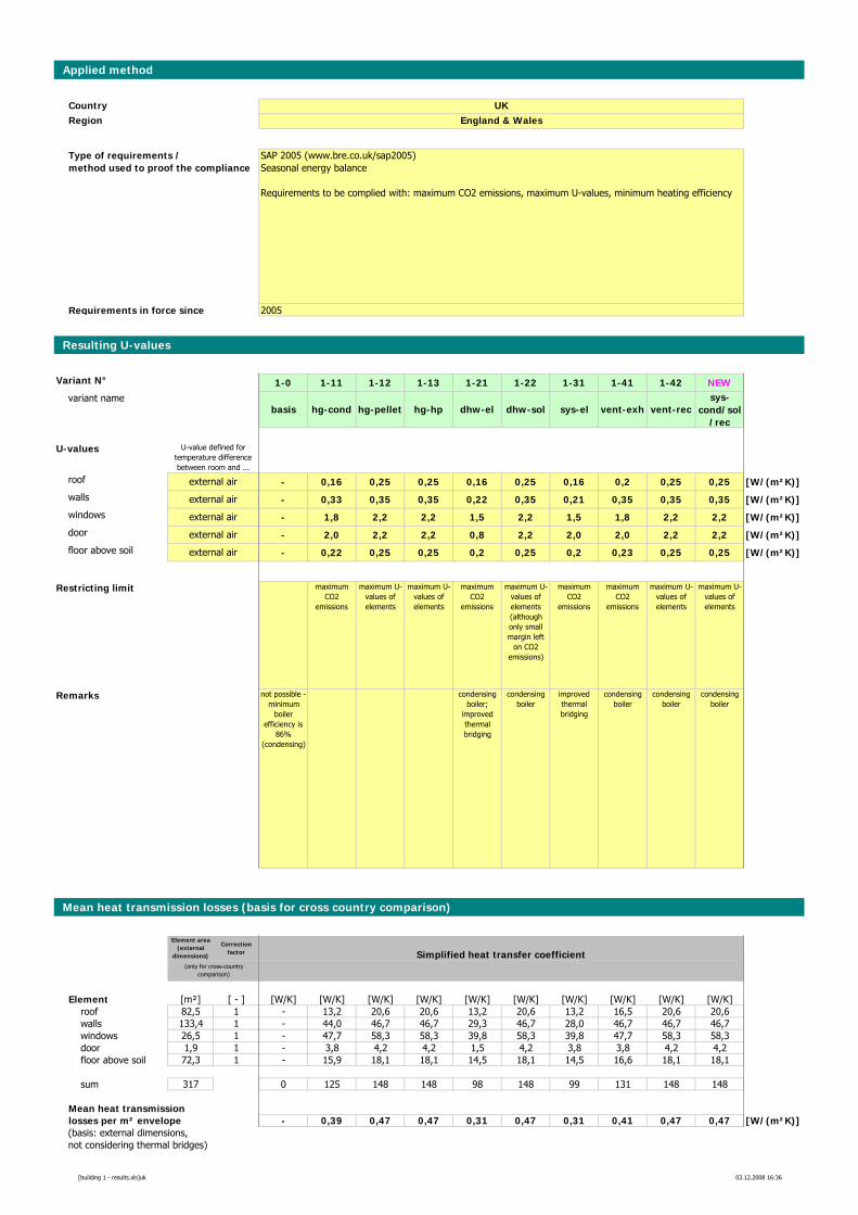
Applied method
CountryRegion
Requirements in force since
Resulting U-values
Variant N° 1-0 1-11 1-12 1-13 1-21 1-22 1-31 1-41 1-42 NEWvariant name
basis hg-cond hg-pellet hg-hp dhw-el dhw-sol sys-el vent-exh vent-recsys-
cond/sol/rec
U-values
roof - 0,16 0,25 0,25 0,16 0,25 0,16 0,2 0,25 0,25 [W/(m²K)]walls - 0,33 0,35 0,35 0,22 0,35 0,21 0,35 0,35 0,35 [W/(m²K)]windows - 1,8 2,2 2,2 1,5 2,2 1,5 1,8 2,2 2,2 [W/(m²K)]door - 2,0 2,2 2,2 0,8 2,2 2,0 2,0 2,2 2,2 [W/(m²K)]floor above soil - 0,22 0,25 0,25 0,2 0,25 0,2 0,23 0,25 0,25 [W/(m²K)]
Restricting limit maximum CO2
emissions
maximum U-values of elements
maximum U-values of elements
maximum CO2
emissions
maximum U-values of elements (although only small margin left
on CO2 emissions)
maximum CO2
emissions
maximum CO2
emissions
maximum U-values of elements
maximum U-values of elements
Remarks not possible - minimum
boiler efficiency is
86% (condensing)
condensing boiler;
improved thermal bridging
condensing boiler
improved thermal bridging
condensing boiler
condensing boiler
condensing boiler
Mean heat transmission losses (basis for cross country comparison)
Element area (external
dimensions)
Correction factor Simplified heat transfer coefficient
Element [m²] [ - ] [W/K] [W/K] [W/K] [W/K] [W/K] [W/K] [W/K] [W/K] [W/K] [W/K]roof 82,5 1 - 13,2 20,6 20,6 13,2 20,6 13,2 16,5 20,6 20,6walls 133,4 1 - 44,0 46,7 46,7 29,3 46,7 28,0 46,7 46,7 46,7windows 26,5 1 - 47,7 58,3 58,3 39,8 58,3 39,8 47,7 58,3 58,3door 1,9 1 - 3,8 4,2 4,2 1,5 4,2 3,8 3,8 4,2 4,2floor above soil 72,3 1 - 15,9 18,1 18,1 14,5 18,1 14,5 16,6 18,1 18,1
sum 317 0 125 148 148 98 148 99 131 148 148
Mean heat transmissionlosses per m² envelope - 0,39 0,47 0,47 0,31 0,47 0,31 0,41 0,47 0,47 [W/(m²K)](basis: external dimensions,not considering thermal bridges)
(only for cross-country comparison)
external air
external air
external air
external air
external air
SAP 2005 (www.bre.co.uk/sap2005) Seasonal energy balance
Requirements to be complied with: maximum CO2 emissions, maximum U-values, minimum heating efficiency
UKEngland & Wales
U-value defined for temperature difference between room and ...
2005
Type of requirements / method used to proof the compliance
[building 1 - results.xls]uk 03.12.2008 16:36
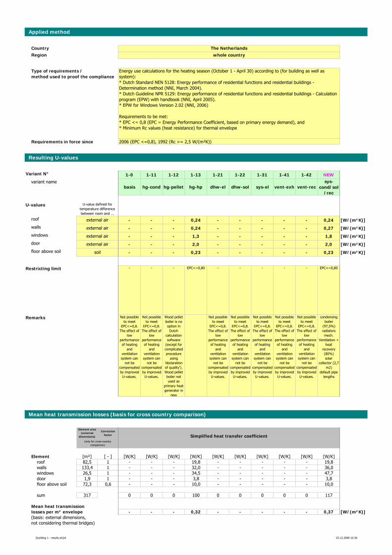
Applied method
CountryRegion
Requirements in force since
Resulting U-values
Variant N° 1-0 1-11 1-12 1-13 1-21 1-22 1-31 1-41 1-42 NEWvariant name
basis hg-cond hg-pellet hg-hp dhw-el dhw-sol sys-el vent-exh vent-recsys-
cond/sol/rec
U-values
roof - - - 0,24 - - - - - 0,24 [W/(m²K)]walls - - - 0,24 - - - - - 0,27 [W/(m²K)]windows - - - 1,3 - - - - - 1,8 [W/(m²K)]door - - - 2,0 - - - - - 2,0 [W/(m²K)]floor above soil - - - 0,23 - - - - - 0,23 [W/(m²K)]
Restricting limit - - - EPC<=0,80 - - - - - EPC<=0,80
Remarks Not possible to meet
EPC<=0,8. The effect of
low performance of heating
and ventilation system can
not be compensated by improved
U-values.
Not possible to meet
EPC<=0,8. The effect of
low performance of heating
and ventilation system can
not be compensated by improved
U-values.
Wood pellet boiler is no option in
Dutch calculation software
(except for complicated procedure
using 'declaration of quality'). Wood pellet boiler not used as
primary heat generator in
new
Not possible to meet
EPC<=0,8. The effect of
low performance of heating
and ventilation system can
not be compensated by improved
U-values.
Not possible to meet
EPC<=0,8. The effect of
low performance of heating
and ventilation system can
not be compensated by improved
U-values.
Not possible to meet
EPC<=0,8. The effect of
low performance of heating
and ventilation system can
not be compensated by improved
U-values.
Not possible to meet
EPC<=0,8. The effect of
low performance of heating
and ventilation system can
not be compensated by improved
U-values.
Not possible to meet
EPC<=0,8. The effect of
low performance of heating
and ventilation system can
not be compensated by improved
U-values.
condensing boiler
(97,5%)radiatorsmech.
Ventilation + heat
recovery (80%)solar
collector (2,7 m2)
default pipe lengths
Mean heat transmission losses (basis for cross country comparison)
Element area (external
dimensions)
Correction factor Simplified heat transfer coefficient
Element [m²] [ - ] [W/K] [W/K] [W/K] [W/K] [W/K] [W/K] [W/K] [W/K] [W/K] [W/K]roof 82,5 1 - - - 19,8 - - - - - 19,8walls 133,4 1 - - - 32,0 - - - - - 36,0windows 26,5 1 - - - 34,5 - - - - - 47,7door 1,9 1 - - - 3,8 - - - - - 3,8floor above soil 72,3 0,6 - - - 10,0 - - - - - 10,0
sum 317 0 0 0 100 0 0 0 0 0 117
Mean heat transmissionlosses per m² envelope - - - 0,32 - - - - - 0,37 [W/(m²K)](basis: external dimensions,not considering thermal bridges)
(only for cross-country comparison)
Energy use calculations for the heating season (October 1 - April 30) according to (for building as well as system):* Dutch Standard NEN 5128: Energy performance of residential functions and residential buildings - Determination method (NNI, March 2004).* Dutch Guideline NPR 5129: Energy performance of residential functions and residential buildings - Calculation program (EPW) with handbook (NNI, April 2005). * EPW for Windows Version 2.02 (NNI, 2006)
Requirements to be met:* EPC <= 0,8 (EPC = Energy Performance Coefficient, based on primary energy demand), and* Minimum Rc values (heat resistance) for thermal envelope
The Netherlandswhole country
U-value defined for temperature difference between room and ...
soil
external air
external air
external air
external air
2006 (EPC <=0,8), 1992 (Rc >= 2,5 W/(m²K))
Type of requirements / method used to proof the compliance
[building 1 - results.xls]nl 03.12.2008 16:36
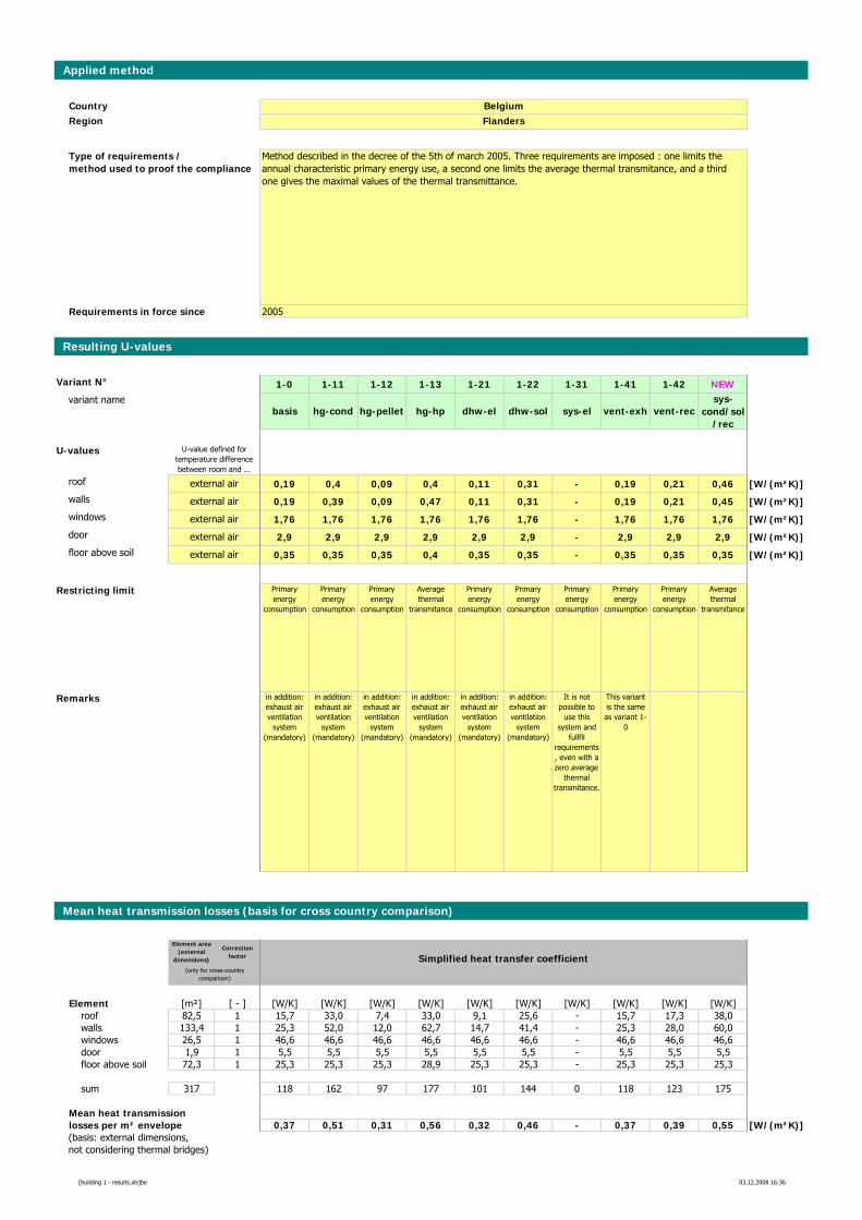
Applied method
CountryRegion
Requirements in force since
Resulting U-values
Variant N° 1-0 1-11 1-12 1-13 1-21 1-22 1-31 1-41 1-42 NEWvariant name
basis hg-cond hg-pellet hg-hp dhw-el dhw-sol sys-el vent-exh vent-recsys-
cond/sol/rec
U-values
roof 0,19 0,4 0,09 0,4 0,11 0,31 - 0,19 0,21 0,46 [W/(m²K)]walls 0,19 0,39 0,09 0,47 0,11 0,31 - 0,19 0,21 0,45 [W/(m²K)]windows 1,76 1,76 1,76 1,76 1,76 1,76 - 1,76 1,76 1,76 [W/(m²K)]door 2,9 2,9 2,9 2,9 2,9 2,9 - 2,9 2,9 2,9 [W/(m²K)]floor above soil 0,35 0,35 0,35 0,4 0,35 0,35 - 0,35 0,35 0,35 [W/(m²K)]
Restricting limit Primary energy
consumption
Primary energy
consumption
Primary energy
consumption
Average thermal
transmitance
Primary energy
consumption
Primary energy
consumption
Primary energy
consumption
Primary energy
consumption
Primary energy
consumption
Average thermal
transmitance
Remarks in addition: exhaust air ventilation
system (mandatory)
in addition: exhaust air ventilation
system (mandatory)
in addition: exhaust air ventilation
system (mandatory)
in addition: exhaust air ventilation
system (mandatory)
in addition: exhaust air ventilation
system (mandatory)
in addition: exhaust air ventilation
system (mandatory)
It is not possible to
use this system and
fullfil requirements, even with a zero average
thermal transmitance.
This variant is the same as variant 1-
0
Mean heat transmission losses (basis for cross country comparison)
Element area (external
dimensions)
Correction factor Simplified heat transfer coefficient
Element [m²] [ - ] [W/K] [W/K] [W/K] [W/K] [W/K] [W/K] [W/K] [W/K] [W/K] [W/K]roof 82,5 1 15,7 33,0 7,4 33,0 9,1 25,6 - 15,7 17,3 38,0walls 133,4 1 25,3 52,0 12,0 62,7 14,7 41,4 - 25,3 28,0 60,0windows 26,5 1 46,6 46,6 46,6 46,6 46,6 46,6 - 46,6 46,6 46,6door 1,9 1 5,5 5,5 5,5 5,5 5,5 5,5 - 5,5 5,5 5,5floor above soil 72,3 1 25,3 25,3 25,3 28,9 25,3 25,3 - 25,3 25,3 25,3
sum 317 118 162 97 177 101 144 0 118 123 175
Mean heat transmissionlosses per m² envelope 0,37 0,51 0,31 0,56 0,32 0,46 - 0,37 0,39 0,55 [W/(m²K)](basis: external dimensions,not considering thermal bridges)
(only for cross-country comparison)
external air
external air
external air
external air
external air
Method described in the decree of the 5th of march 2005. Three requirements are imposed : one limits the annual characteristic primary energy use, a second one limits the average thermal transmitance, and a third one gives the maximal values of the thermal transmittance.
BelgiumFlanders
U-value defined for temperature difference between room and ...
2005
Type of requirements / method used to proof the compliance
[building 1 - results.xls]be 03.12.2008 16:36
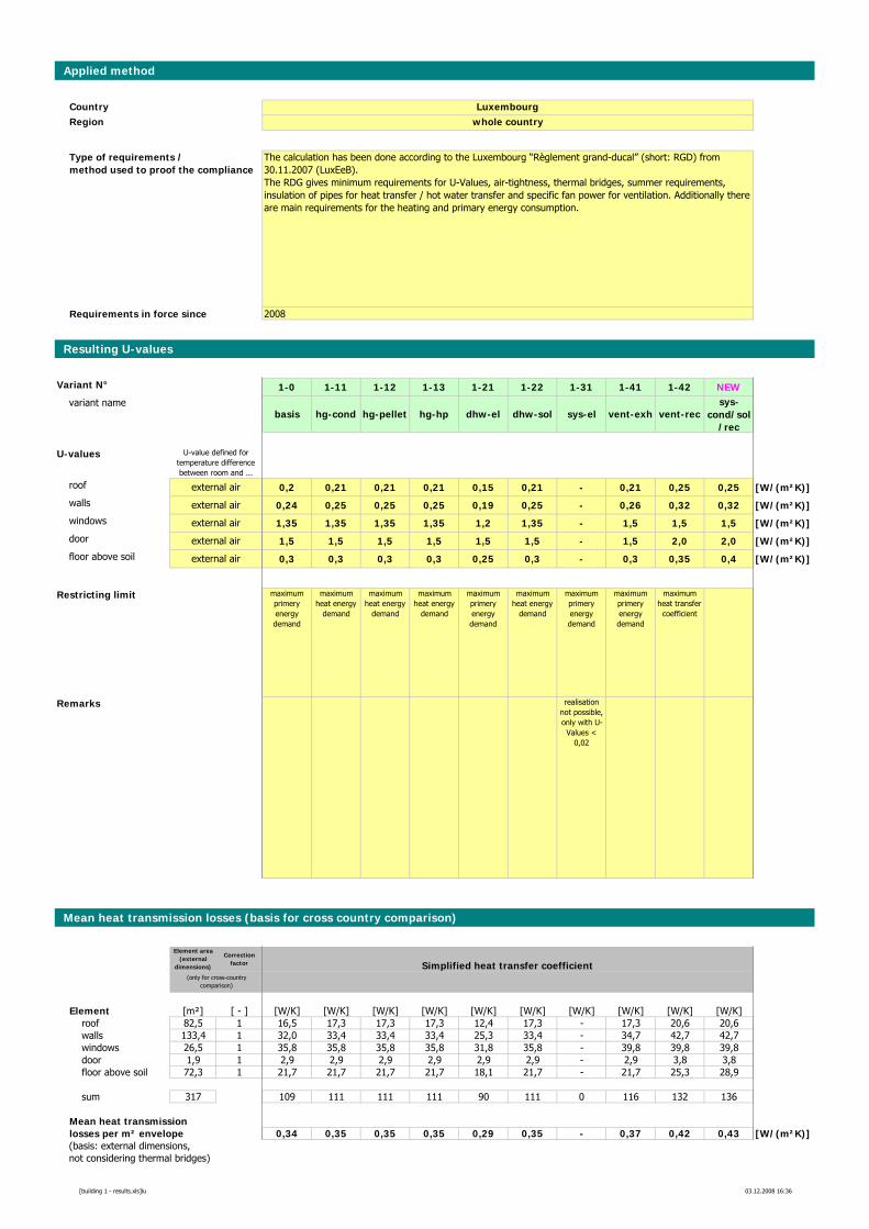
Applied method
CountryRegion
Requirements in force since
Resulting U-values
Variant N° 1-0 1-11 1-12 1-13 1-21 1-22 1-31 1-41 1-42 NEWvariant name
basis hg-cond hg-pellet hg-hp dhw-el dhw-sol sys-el vent-exh vent-recsys-
cond/sol/rec
U-values
roof 0,2 0,21 0,21 0,21 0,15 0,21 - 0,21 0,25 0,25 [W/(m²K)]walls 0,24 0,25 0,25 0,25 0,19 0,25 - 0,26 0,32 0,32 [W/(m²K)]windows 1,35 1,35 1,35 1,35 1,2 1,35 - 1,5 1,5 1,5 [W/(m²K)]door 1,5 1,5 1,5 1,5 1,5 1,5 - 1,5 2,0 2,0 [W/(m²K)]floor above soil 0,3 0,3 0,3 0,3 0,25 0,3 - 0,3 0,35 0,4 [W/(m²K)]
Restricting limit maximum primery energy demand
maximum heat energy
demand
maximum heat energy
demand
maximum heat energy
demand
maximum primery energy demand
maximum heat energy
demand
maximum primery energy demand
maximum primery energy demand
maximum heat transfer
coefficient
Remarks realisation not possible, only with U-
Values < 0,02
Mean heat transmission losses (basis for cross country comparison)
Element area (external
dimensions)
Correction factor Simplified heat transfer coefficient
Element [m²] [ - ] [W/K] [W/K] [W/K] [W/K] [W/K] [W/K] [W/K] [W/K] [W/K] [W/K]roof 82,5 1 16,5 17,3 17,3 17,3 12,4 17,3 - 17,3 20,6 20,6walls 133,4 1 32,0 33,4 33,4 33,4 25,3 33,4 - 34,7 42,7 42,7windows 26,5 1 35,8 35,8 35,8 35,8 31,8 35,8 - 39,8 39,8 39,8door 1,9 1 2,9 2,9 2,9 2,9 2,9 2,9 - 2,9 3,8 3,8floor above soil 72,3 1 21,7 21,7 21,7 21,7 18,1 21,7 - 21,7 25,3 28,9
sum 317 109 111 111 111 90 111 0 116 132 136
Mean heat transmissionlosses per m² envelope 0,34 0,35 0,35 0,35 0,29 0,35 - 0,37 0,42 0,43 [W/(m²K)](basis: external dimensions,not considering thermal bridges)
(only for cross-country comparison)
The calculation has been done according to the Luxembourg “Règlement grand-ducal” (short: RGD) from 30.11.2007 (LuxEeB).The RDG gives minimum requirements for U-Values, air-tightness, thermal bridges, summer requirements, insulation of pipes for heat transfer / hot water transfer and specific fan power for ventilation. Additionally there are main requirements for the heating and primary energy consumption.
Luxembourgwhole country
U-value defined for temperature difference between room and ...
external air
external air
external air
external air
external air
2008
Type of requirements / method used to proof the compliance
[building 1 - results.xls]lu 03.12.2008 16:36
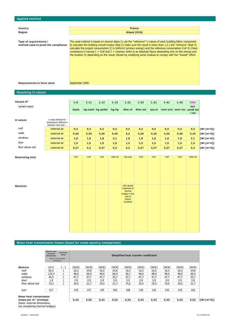
Applied method
CountryRegion
Requirements in force since
Resulting U-values
Variant N° 1-0 1-11 1-12 1-13 1-21 1-22 1-31 1-41 1-42 NEWvariant name
basis hg-cond hg-pellet hg-hp dhw-el dhw-sol sys-el vent-exh vent-recsys-
cond/sol/rec
U-values
roof 0,2 0,3 0,2 0,3 0,2 0,2 0,2 0,2 0,2 0,3 [W/(m²K)]walls 0,36 0,45 0,36 0,45 0,2 0,36 0,36 0,36 0,36 0,45 [W/(m²K)]windows 1,8 1,8 1,8 2,1 1,8 1,8 1,8 1,8 1,8 2,1 [W/(m²K)]door 1,5 1,5 1,5 1,5 1,3 1,5 1,5 1,5 1,5 1,5 [W/(m²K)]floor above soil 0,27 0,3 0,27 0,3 0,2 0,27 0,27 0,27 0,27 0,3 [W/(m²K)]
Restricting limit Cref Cref Cref Ubat ref Cep max Cref Cref Cref Cref Ubat ref
Remarks with special treatment of
thermal bridges in the
case of interior
insulation
Mean heat transmission losses (basis for cross country comparison)
Element area (external
dimensions)
Correction factor Simplified heat transfer coefficient
Element [m²] [ - ] [W/K] [W/K] [W/K] [W/K] [W/K] [W/K] [W/K] [W/K] [W/K] [W/K]roof 82,5 1 16,5 24,8 16,5 24,8 16,5 16,5 16,5 16,5 16,5 24,8walls 133,4 1 48,0 60,0 48,0 60,0 26,7 48,0 48,0 48,0 48,0 60,0windows 26,5 1 47,7 47,7 47,7 55,7 47,7 47,7 47,7 47,7 47,7 55,7door 1,9 1 2,9 2,9 2,9 2,9 2,5 2,9 2,9 2,9 2,9 2,9floor above soil 72,3 1 19,5 21,7 19,5 21,7 14,5 19,5 19,5 19,5 19,5 21,7
sum 317 135 157 135 165 108 135 135 135 135 165
Mean heat transmissionlosses per m² envelope 0,43 0,50 0,43 0,52 0,34 0,43 0,43 0,43 0,43 0,52 [W/(m²K)](basis: external dimensions,not considering thermal bridges)
(only for cross-country comparison)
external air
external air
external air
external air
external air
The used method is based on several steps:1) use the "reference" U values of each building fabric component to calculate the building overall Uvalue Ubat 2) make sure the result is lower than 1,2 x the "refrence" Ubat 3) calculate the project consumption (C in kWh/m2 primary energy) and the reference consumption Cref 4) Check compliance in having C < Cref and C < Cepmax which is an absolute figure depending only on the energy and the location 5) depending on the result, iterate by modifying some Uvalues to comply with the "lowest" effort.
FranceAlsace (H1b)
U-value defined for temperature difference between room and ...
September 2006
Type of requirements / method used to proof the compliance
[building 1 - results.xls]fr 03.12.2008 16:36
Energy Performance Requirements for New Buildings – Exemplary Comparison
Appendix 2: Definition of Model Building 2 – multi-family house
Appendix 2a: Plans
A-27
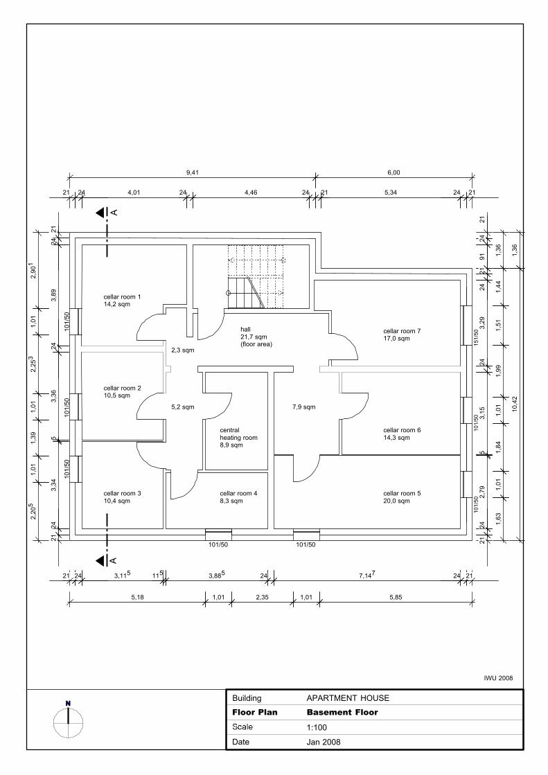
2124
3,89
243,
365
3,34
2421
5,18 1,01 2,35 1,01 5,85
21 24 3,115 115 3,885 24 7,147 24 21
2124
9121
243,
2924
3,15
52,
7924
21
21 24 4,01 24 4,46 24 21 5,34 24 21
101/
50
cellar room 114,2 sqm
5,2 sqm
hall21,7 sqm(floor area)
NAPARTMENT HOUSE
Floor Plan Basement Floor
1:100
Date Jan 2008
Building
IWU 2008
AA
cellar room 210,5 sqm
cellar room 310,4 sqm
cellar room 48,3 sqm
central heating room8,9 sqm
cellar room 520,0 sqm
cellar room 614,3 sqm
cellar room 717,0 sqm
7,9 sqm
2,3 sqm
101/
5010
1/50
101/
50
101/50101/50
9,41 6,00
2,90
11,
012,
253
1,01
1,39
1,01
2,20
5
1,36
1,44
1,51
1,99
1,01
1,84
1,01
1,63
1,36
10,4
2
151/
5010
1/50
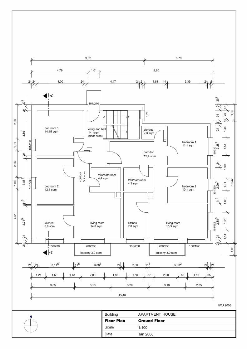
209
243,
891
243,
888
115
2,74
524
21
1,21 1,50 1,48 2,00 1,86 1,50 87 2,00 83 1,50 65
21 24 3,115 115 3,885 24 2,00 115 5,032 24 21
209
2491
2124
3,28
724
2,99
311
52,
885
2421
21 24 4,00 24 4,47 24 21 1,81 14 3,39 24 21
NFloor Plan Ground Floor
1:100
Date Jan 2008
Building APARTMENT HOUSE
IWU 2008
bedroom 114,15 sqm
living room14,8 sqm
WC/bathroom4,4 sqm
101/
230
151/
230
150/152150/230150/230 200/230 200/230
151/
152
0,76
AA
101/210
entry and hall14,1sqm(floor area)
balcony 3,0 sqm
bedroom 212,1 sqm
kitchen8,6 sqm
corr
idor
5,2
sqm
balcony 3,0 sqm
storage2,3 sqm
bedroom 111,1 sqm
bedroom 210,1 sqm
living room15,3 sqm
corridor12,4 sqm
101/
230
101/
230
3,65 3,10 3,20 3,10 2,35
15,40
2,90
1,01
2,26
1,00
4,61
4,79 1,01 9,60
9,62 5,79
1,36
10,4
21,
05
WC/bathroom4,3 sqm
kitchen7,8 sqm
4576
151,
441,
511,
991,
011,
831,
511,
14

NFloor Plan First Floor
1:100
Date Jan 2008
Building APARTMENT HOUSE
IWU 2008
AA
bedroom 114,15 sqm
living room14,8 sqm
hall14,1sqm(floor area)
bedroom 212,1 sqm
kitchen8,6 sqm
corr
idor
5,2
sqm
storage2,3 sqm
bedroom 111,1 sqm
bedroom 210,1 sqm
living room15,3 sqm
corridor12,4 sqm
WC/bathroom4,3 sqm
kitchen7,8 sqm
WC/bathroom4,4 sqm
209
243,
891
243,
888
115
2,74
524
21
1,21 1,50 1,48 2,00 1,86 1,50 87 2,00 83 1,50 65
21 24 3,115 115 3,885 24 2,00 115 5,032 24 21
209
2491
2124
3,28
724
2,99
311
52,
885
2421
21 24 4,00 24 4,47 24 21 1,81 14 3,39 24 21
3,65 3,10 3,20 3,10 2,35
15,40
2,90
1,01
2,26
1,00
4,61
9,62 5,79
1,36
10,4
21,
05
4576
151,
441,
511,
991,
011,
831,
511,
14
101/
230
151/
230
150/152150/230150/230 200/230 200/230
151/
152
0,76
balcony 3,0 sqm balcony 3,0 sqm
101/
230
101/
230
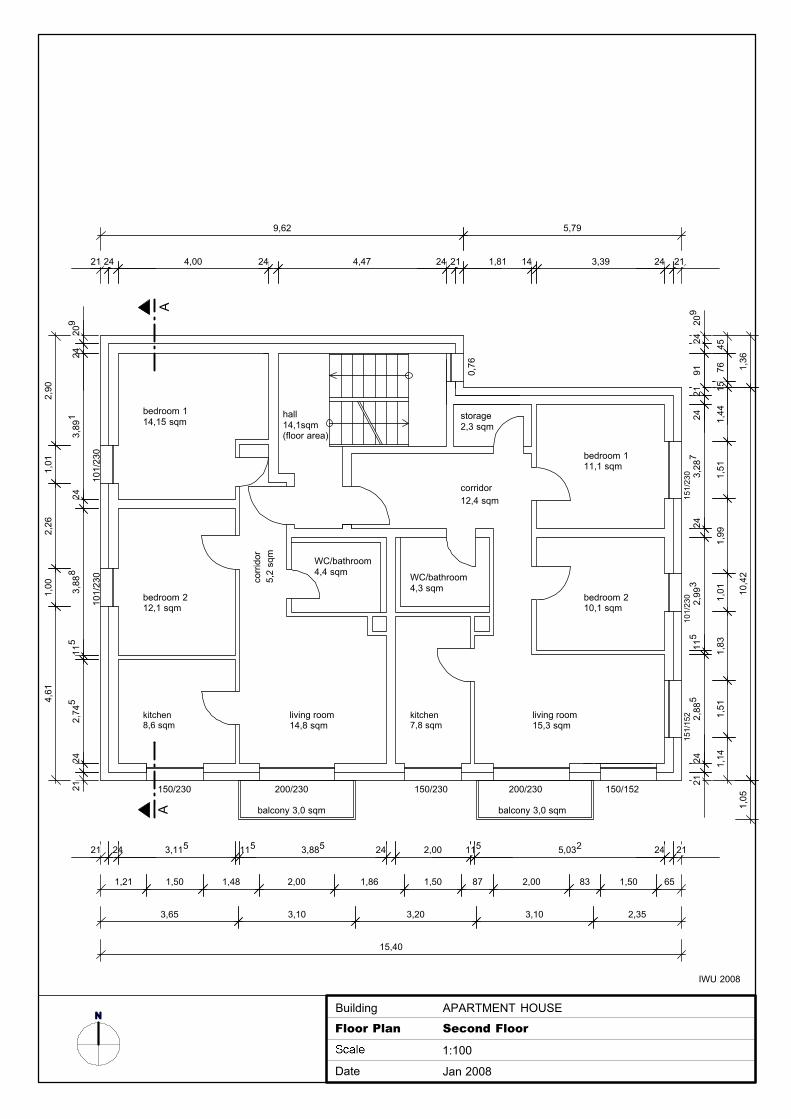
NFloor Plan Second Floor
1:100
Date Jan 2008
Building APARTMENT HOUSE
IWU 2008
AA
bedroom 114,15 sqm
living room14,8 sqm
hall14,1sqm(floor area)
bedroom 212,1 sqm
kitchen8,6 sqm
corr
idor
5,2
sqm
storage2,3 sqm
bedroom 111,1 sqm
bedroom 210,1 sqm
living room15,3 sqm
corridor12,4 sqm
WC/bathroom4,3 sqm
kitchen7,8 sqm
WC/bathroom4,4 sqm
101/
230
151/
230
150/152150/230150/230 200/230 200/230
151/
152
0,76
balcony 3,0 sqm balcony 3,0 sqm
101/
230
101/
230
209
243,
891
243,
888
115
2,74
524
21
1,21 1,50 1,48 2,00 1,86 1,50 87 2,00 83 1,50 65
21 24 3,115 115 3,885 24 2,00 115 5,032 24 21
209
2491
2124
3,28
724
2,99
311
52,
885
2421
21 24 4,00 24 4,47 24 21 1,81 14 3,39 24 21
3,65 3,10 3,20 3,10 2,35
15,40
2,90
1,01
2,26
1,00
4,61
9,62 5,79
1,36
10,4
21,
05
4576
151,
441,
511,
991,
011,
831,
511,
14
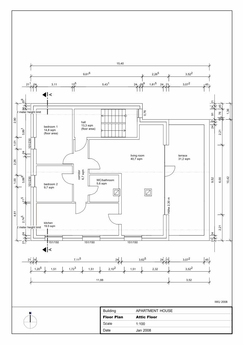
4576
152,
216,
002,
21
2124
9121
249,
5224
21
1,205 1,51 1,723 1,51 2,102 1,51 2,32 3,522
21 24 7,115 24 3,625 24 21 3,072 45
9,616 2,265 3,522
211 24 3,11 175 5,431 24 209 1,815 24 21 3,072 45
151/150 151/150 151/150
Höh
e 2,
30 m
NFloor Plan Attic Floor
1:100
Date Jan 2008
Building APARTMENT HOUSE
IWU 2008
AA
bedroom 114,8 sqm(floor area)
bedroom 29,7 sqm
kitchen19,5 sqm
WC/bathroom5,6 sqm
living room40,7 sqm
terrace31,2 sqm
hall13,3 sqm(floor area)
101/
230
101/
230 corr
idor
6,7
sqm
11,88 3,52
1,36
10,4
2
0,76
15,40
209
243,
891
243,
888
115
2,74
524
21
2,90
1,01
2,26
1,00
4,61
2 meter height limit
2 meter height limit
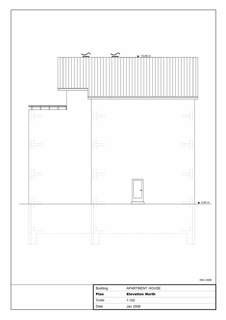
Plan Elevation North
1:100
Date Jan 2008
Building APARTMENT HOUSE
IWU 2008
13,59 m
0,00 m
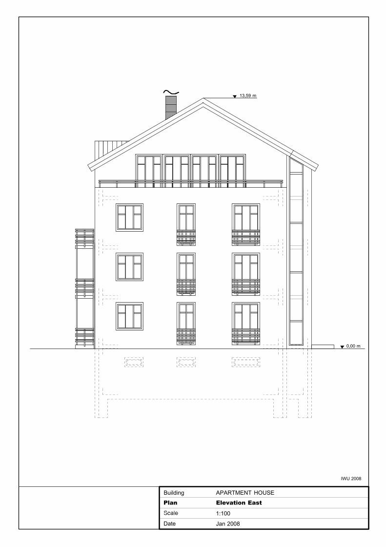
Plan Elevation East
1:100
Date Jan 2008
Building APARTMENT HOUSE
IWU 2008
13,59 m
0,00 m
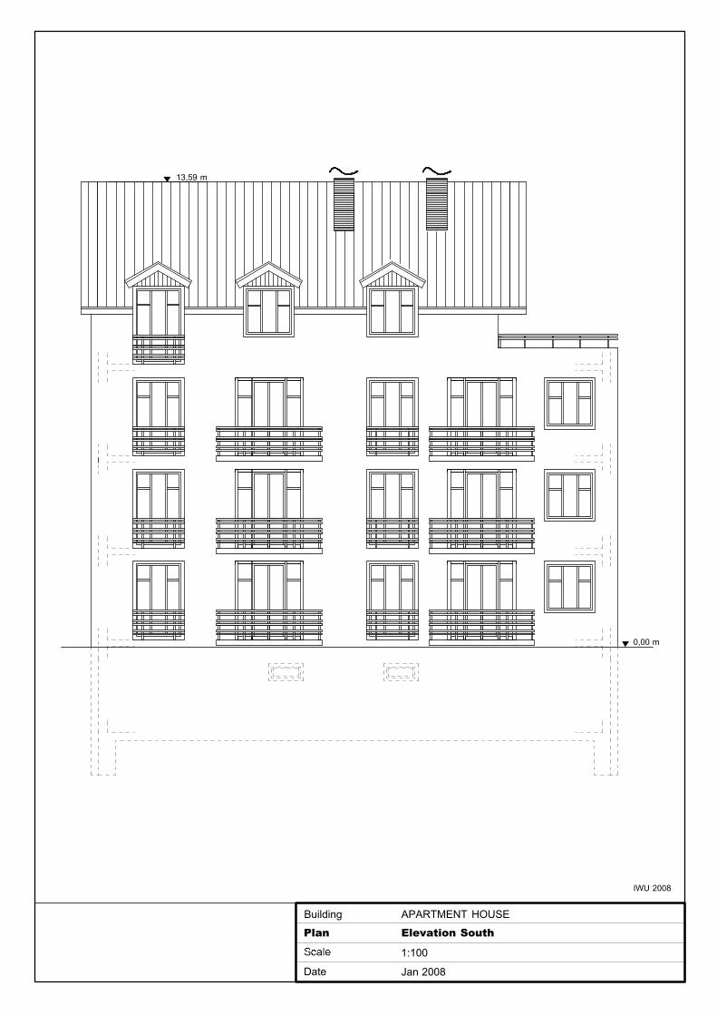
Plan Elevation South
1:100
Date Jan 2008
Building APARTMENT HOUSE
IWU 2008
13,59 m
0,00 m
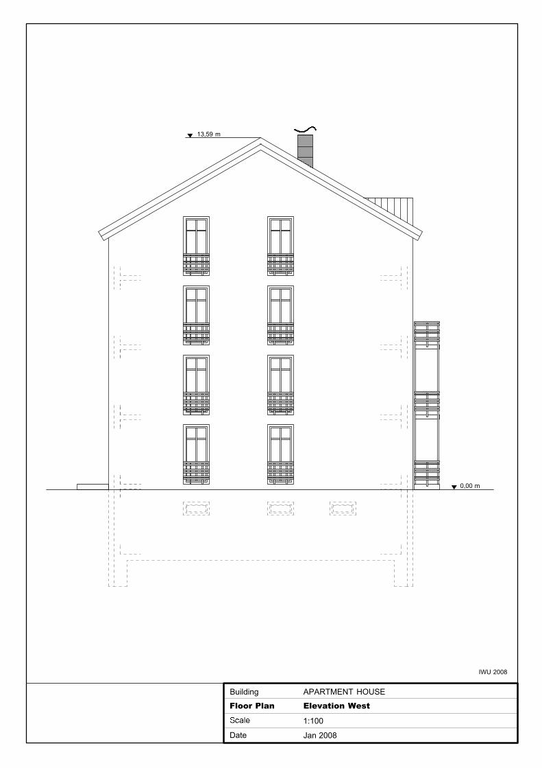
Floor Plan Elevation West
1:100
Date Jan 2008
Building APARTMENT HOUSE
IWU 2008
0,00 m
13,59 m
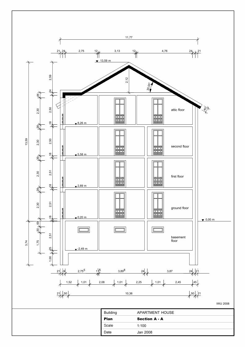
21 24 2,75 12 3,13 12 4,76 24 21
21 50 10,36 50 21
21 24 2,755 115 3,898 24 3,87 24 21
Plan Section A - A
1:100
Date Jan 2008
Building APARTMENT HOUSE
IWU 2008
1,52 1,01 2,08 1,01 2,25 1,01 2,45 45
2,59
242,
5018
2,50
182,
5118
2,51
182,
5125
1,00
442,
3038
2,30
392,
3039
2,30
6950
1,75
13,5
93,
74
second floor
first floor
ground floor
2,89 m
0,20 m
5,58 m
basement floor
8,26 m
-2,49 m
13,59 m
11,77
40
2,12
attic floor
30,0
0°
0,00 m
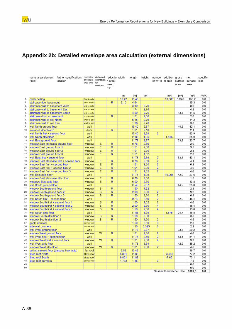
Energy Performance Requirements for New Buildings – Exemplary Comparison
Appendix 2b: Detailed envelope area calculation (external dimensions)
name area element (free)
dedicated envelope area type
dedicated orientation for windows
reduction area: insert "R"
width length height number (if <> 1)
additional area
gross surface area
net surface area
specific loss
[m] [m] [m] [m²] [m²] [m²] [W/K]1. cellar ceiling floor to cellar 10,42 15,40 13,083 173,6 158,2 0,02. staircase floor basement floor to soil R 3,10 4,94 15,3 0,03. staircase wall to basement West wall to cellar 3,10 2,76 8,6 0,04. staircase wall to basement East wall to cellar 1,74 2,76 4,8 0,05. staircase wall to basement South wall to cellar 4,90 2,76 13,5 11,5 0,06. staircase door to basement door to cellar R 1,01 2,00 2,0 0,07. staircase wall to soil North wall to soil 5,15 2,76 14,2 0,08. staircase wall to soil East wall to soil 1,36 2,76 3,8 0,09. wall North ground floor wall 15,40 2,87 44,2 42,1 0,010. entrance door North door R 1,01 2,10 2,1 0,011. wall North first + second floor wall 15,40 2,69 2 82,9 0,012. wall North attic floor wall 11,88 1,95 1,816 25,0 0,013. wall East ground floor wall 11,78 2,87 33,8 23,7 0,014. window East staircase ground floor window E R 0,76 2,69 2,0 0,015. window East ground floor 1 window E R 1,51 2,30 3,5 0,016. window East ground floor 2 window E R 1,01 2,30 2,3 0,017. window East ground floor 3 window E R 1,51 1,52 2,3 0,018. wall East first + second floor wall 11,78 2,69 2 63,4 43,1 0,019. window East staircase first + second floor window E R 0,76 2,69 2 4,1 0,020. window East first + second floor 1 window E R 1,51 2,30 2 6,9 0,021. window East first + second floor 2 window E R 1,01 2,30 2 4,6 0,022. window East first + second floor 3 window E R 1,51 1,52 2 4,6 0,023. wall East attic floor wall 11,78 1,95 19,908 42,9 27,6 0,024. window East staircase attic floor window E R 0,76 2,00 1,5 0,025. windows East attic floor window E R 6,00 2,30 13,8 0,026. wall South ground floor wall 15,40 2,87 44,2 25,8 0,027. window South ground floor 1 window S R 1,50 1,52 2,3 0,028. window South ground floor 2 window S R 2,00 2,30 2 9,2 0,029. window South ground floor 3 window S R 1,50 2,30 2 6,9 0,030. wall South first + second floor wall 15,40 2,69 2 82,9 46,1 0,031. window South first + second floor 1 window S R 1,50 1,52 2 4,6 0,032. window South first + second floor 2 window S R 2,00 2,30 4 18,4 0,033. window South first + second floor 3 window S R 1,50 2,30 4 13,8 0,034. wall South attic floor wall 11,88 1,95 1,575 24,7 16,8 0,035. window South attic floor 1 window S R 1,50 2,30 3,5 0,036. window South attic floor 2 window S R 1,50 1,50 2 4,5 0,037. gable dormers dormer wall 1,50 0,50 3 2,3 0,038. side wall dormers dormer wall 1,10 0,325 6 2,1 0,039. wall West ground floor wall 11,78 2,87 33,8 29,2 0,040. window West ground floor window W R 1,01 2,30 2 4,6 0,041. wall West first + second floor wall 11,78 2,69 2 63,4 54,1 0,042. window West first + second floor window W R 1,01 2,30 4 9,3 0,043. wall West attic floor wall 11,78 3,64 42,9 38,2 0,044. window West attic floor window W R 1,01 2,30 2 4,6 0,045. ceiling second floor (balcony floor attic) flat roof 3,52 10,42 36,7 0,046. tilted roof North tilted roof 6,801 11,88 -3,565 77,2 0,047. tilted roof South tilted roof 6,801 11,88 -7,65 73,1 0,048. tilted roof dormers dormer roof 1,732 1,45 3 7,5 0,049. 0,0 0,050. 0,0 0,0
Gesamt thermische Hülle: 1001,3 0,0
further specification / location
A-38
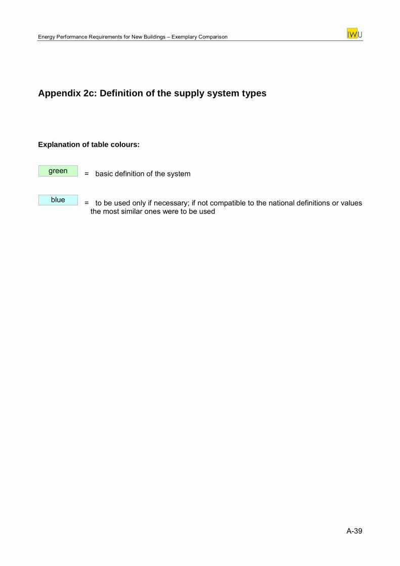
Energy Performance Requirements for New Buildings – Exemplary Comparison
Appendix 2c: Definition of the supply system types
Explanation of table colours:
= basic definition of the system green
= to be used only if necessary; if not compatible to the national definitions or values the most similar ones were to be used
blue
A-39
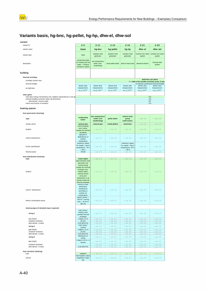
Energy Performance Requirements for New Buildings – Exemplary Comparison
Variants basis, hg-bnc, hg-pellet, hg-hp, dhw-el, dhw-sol variant
variant N° 2-0 2-11 2-12 2-13 2-21 2-22
variant name basis hg-bnc hg-pellet hg-hp dhw-el dhw-sol
variant type basisvariation heat
generatorvariation heat
generatorvariation heat
generatorvariation hot water
systemvariation hot water
system
description
condensing boiler for heating and hot water + exhaust ventilation system
low temperature boiler (non-condensing)
wood pellet boiler electric heat pump decentral electricthermal solar
system
building
thermal envelope
envelope surface areadefinition see plans
(+ table with outside envelope areas, if appthermal bridges no relevant constructive thermal bridges
air-tightnessblower door
measurement: n50 < 1,5 h-1
blower door measurement: n50 < 1,5 h-1
blower door measurement: n50 < 1,5 h-1
blower door measurement: n50 < 1,5 h-1
blower door measurement: n50 < 1,5 h-1
blower door measurement: n50 < 1,5 h-1
solar gainstotal solar energy transmittance (for radiation perpendicular to the gla 0,6external shading correction factor (all directions) 0,6
alternatively: horizon angle 30°frame area fraction of windows 0,3
heating system
heat generation (heating)
typecondensing
boiler
low temperature boiler (not
condensing)pellet boiler
electric heat pump
(soil/water)= var. 2-0 = var. 2-0
energy carrier natural gas natural gas wood pellets electricity = var. 2-0 = var. 2-0
location
central heating room (cellar,
outside the thermal envelope)
= var. 2-0 = var. 2-0 = var. 2-0 = var. 2-0 = var. 2-0
control temperature
adjusted in dependence of
outdoor temperature
= var. 2-0 = var. 2-0 = var. 2-0 = var. 2-0 = var. 2-0
further specification
maximum values for supply / return temperature: 70°C
/ 55°C
= var. 2-0 = var. 2-0
maximum values for supply / return temperature: 55°C
/ 45°C
= var. 2-0 = var. 2-0
thermal power 30 kW = var. 2-0 = var. 2-0 = var. 2-0 = var. 2-0 = var. 2-0
heat distribution (heating)type water pipes = var. 2-0 = var. 2-0 = var. 2-0 = var. 2-0 = var. 2-0
location
pipes between heat generator and vertical string
outside the thermal envelope (non-heated cellar), vertical central
string and distribution in all storeys inside the thermal envelope
= var. 2-0 = var. 2-0 = var. 2-0 = var. 2-0 = var. 2-0
control temperature
control of heat distribution temperature according to outdoor air temperature
= var. 2-0 = var. 2-0 = var. 2-0 = var. 2-0 = var. 2-0
electric consumption pump
electric power = 160 W / running time = 20 h/d x
365 d/a
= var. 2-0 = var. 2-0 = var. 2-0 = var. 2-0 = var. 2-0
heating pipes (if detailed input required)
string 1
main string / heating room
(outside thermal envelope)
= var. 2-0 = var. 2-0 = var. 2-0 = var. 2-0 = var. 2-0
pipe length 2 pipes x 5 m = var. 2-0 = var. 2-0 = var. 2-0 = var. 2-0 = var. 2-0insulation thickness 20 mm = var. 2-0 = var. 2-0 = var. 2-0 = var. 2-0 = var. 2-0alternatively: U-value 0,20 W/(m²K) = var. 2-0 = var. 2-0 = var. 2-0 = var. 2-0 = var. 2-0
string 2main string /
vertical= var. 2-0 = var. 2-0 = var. 2-0 = var. 2-0 = var. 2-0
pipe length 2 pipes x 11 m = var. 2-0 = var. 2-0 = var. 2-0 = var. 2-0 = var. 2-0insulation thickness 20 mm = var. 2-0 = var. 2-0 = var. 2-0 = var. 2-0 = var. 2-0alternatively: U-value 0,20 W/(m²K) = var. 2-0 = var. 2-0 = var. 2-0 = var. 2-0 = var. 2-0
string 3 distribution in rooms
= var. 2-0 = var. 2-0 = var. 2-0 = var. 2-0 = var. 2-0
pipe length2 pipes x 40 m x 4
storeys= var. 2-0 = var. 2-0 = var. 2-0 = var. 2-0 = var. 2-0
insulation thickness - = var. 2-0 = var. 2-0 = var. 2-0 = var. 2-0 = var. 2-0alternatively: U-value 0,40 W/(m²K) = var. 2-0 = var. 2-0 = var. 2-0 = var. 2-0 = var. 2-0
heat emission (heating)type radiators = var. 2-0 = var. 2-0 = var. 2-0 = var. 2-0 = var. 2-0
controlthermostatic valves (regulation range:
2K)= var. 2-0 = var. 2-0 = var. 2-0 = var. 2-0 = var. 2-0
A-40
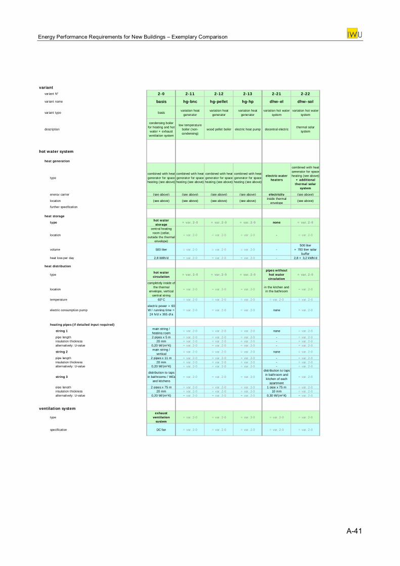
Energy Performance Requirements for New Buildings – Exemplary Comparison
variant
variant N° 2-0 2-11 2-12 2-13 2-21 2-22
variant name basis hg-bnc hg-pellet hg-hp dhw-el dhw-sol
variant type basisvariation heat
generatorvariation heat
generatorvariation heat
generatorvariation hot water
systemvariation hot water
system
description
condensing boiler for heating and hot water + exhaust ventilation system
low temperature boiler (non-condensing)
wood pellet boiler electric heat pump decentral electricthermal solar
system
hot water system
heat generation
typecombined with heat generator for space heating (see above)
combined with heat generator for space heating (see above)
combined with heat generator for space heating (see above)
combined with heat generator for space heating (see above)
electric water heaters
combined with heat generator for space heating (see above)
+ additional thermal solar
system
energy carrier (see above) (see above) (see above) (see above) electricity (see above)
location (see above) (see above) (see above) (see above)inside thermal
envelope(see above)
further specification
heat storage
typehot water storage
= var. 2-0 = var. 2-0 = var. 2-0 none = var. 2-0
location
central heating room (cellar,
outside the thermal envelope)
= var. 2-0 = var. 2-0 = var. 2-0 - = var. 2-0
volume 500 liter = var. 2-0 = var. 2-0 = var. 2-0 -500 liter
+ 700 liter solar buffer
heat loss per day 2,8 kWh/d = var. 2-0 = var. 2-0 = var. 2-0 - 2,8 + 3,2 kWh/d
heat distribution
typehot water circulation
= var. 2-0 = var. 2-0 = var. 2-0pipes without
hot water circulation
= var. 2-0
location
completely inside of the thermal
envelope, vertical central string
= var. 2-0 = var. 2-0 = var. 2-0in the kitchen and in the bathroom = var. 2-0
temperature 60°C = var. 2-0 = var. 2-0 = var. 2-0 = var. 2-0 = var. 2-0
electric consumption pumpelectric power = 60 W / running time = 24 h/d x 365 d/a
= var. 2-0 = var. 2-0 = var. 2-0 none = var. 2-0
heating pipes (if detailed input required)
string 1main string / heating room
= var. 2-0 = var. 2-0 = var. 2-0 none = var. 2-0
pipe length 2 pipes x 5 m = var. 2-0 = var. 2-0 = var. 2-0 - = var. 2-0insulation thickness 20 mm = var. 2-0 = var. 2-0 = var. 2-0 - = var. 2-0alternatively: U-value 0,20 W/(m²K) = var. 2-0 = var. 2-0 = var. 2-0 - = var. 2-0
string 2main string /
vertical= var. 2-0 = var. 2-0 = var. 2-0 none = var. 2-0
pipe length 2 pipes x 11 m = var. 2-0 = var. 2-0 = var. 2-0 - = var. 2-0insulation thickness 20 mm = var. 2-0 = var. 2-0 = var. 2-0 - = var. 2-0alternatively: U-value 0,20 W/(m²K) = var. 2-0 = var. 2-0 = var. 2-0 - = var. 2-0
string 3distribution to taps in bathrooms / WCs
and kitchens= var. 2-0 = var. 2-0 = var. 2-0
distribution to taps in bathroom and kitchen of each
apartment
= var. 2-0
pipe length 2 pipes x 75 m = var. 2-0 = var. 2-0 = var. 2-0 1 pipe x 75 m = var. 2-0insulation thickness 20 mm = var. 2-0 = var. 2-0 = var. 2-0 10 mm = var. 2-0alternatively: U-value 0,20 W/(m²K) = var. 2-0 = var. 2-0 = var. 2-0 0,30 W/(m²K) = var. 2-0
ventilation system
typeexhaust
ventilation system
= var. 2-0 = var. 2-0 = var. 2-0 = var. 2-0 = var. 2-0
specification DC fan = var. 2-0 = var. 2-0 = var. 2-0 = var. 2-0 = var. 2-0
A-41
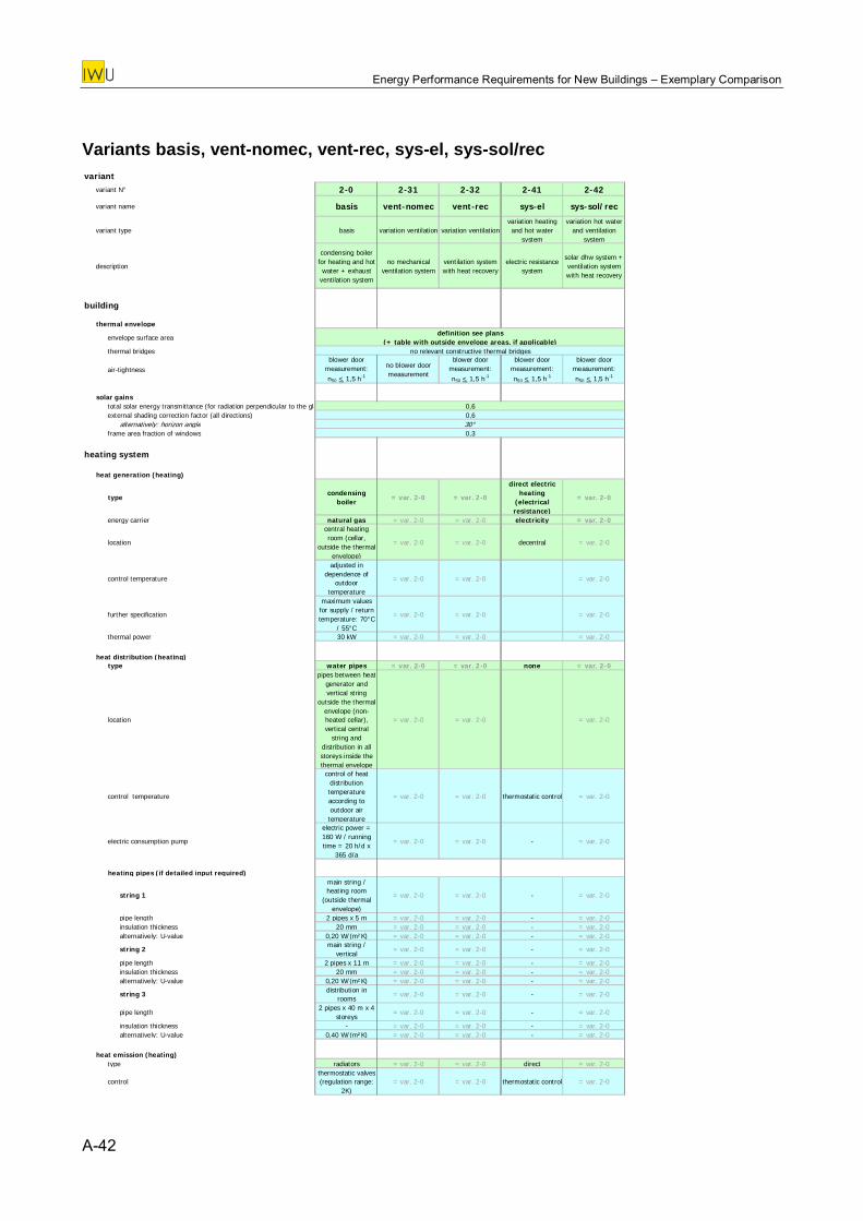
Energy Performance Requirements for New Buildings – Exemplary Comparison
Variants basis, vent-nomec, vent-rec, sys-el, sys-sol/rec variant
variant N° 2-0 2-31 2-32 2-41 2-42
variant name basis vent-nomec vent-rec sys-el sys-sol/rec
variant type basis variation ventilation variation ventilationvariation heating and hot water
system
variation hot water and ventilation
system
description
condensing boiler for heating and hot water + exhaust
ventilation system
no mechanical ventilation system
ventilation system with heat recovery
electric resistance system
solar dhw system + ventilation system with heat recovery
building
thermal envelope
envelope surface areadefinition see plans
(+ table with outside envelope areas, if applicable)thermal bridges no relevant constructive thermal bridges
air-tightnessblower door
measurement: n50 < 1,5 h-1
no blower door measurement
blower door measurement: n50 < 1,5 h-1
blower door measurement: n50 < 1,5 h-1
blower door measurement: n50 < 1,5 h-1
solar gainstotal solar energy transmittance (for radiation perpendicular to the gla 0,6external shading correction factor (all directions) 0,6
alternatively: horizon angle 30°frame area fraction of windows 0,3
heating system
heat generation (heating)
typecondensing
boiler= var. 2-0 = var. 2-0
direct electric heating
(electrical resistance)
= var. 2-0
energy carrier natural gas = var. 2-0 = var. 2-0 electricity = var. 2-0
location
central heating room (cellar,
outside the thermal envelope)
= var. 2-0 = var. 2-0 decentral = var. 2-0
control temperature
adjusted in dependence of
outdoor temperature
= var. 2-0 = var. 2-0 = var. 2-0
further specification
maximum values for supply / return temperature: 70°C
/ 55°C
= var. 2-0 = var. 2-0 = var. 2-0
thermal power 30 kW = var. 2-0 = var. 2-0 = var. 2-0
heat distribution (heating)type water pipes = var. 2-0 = var. 2-0 none = var. 2-0
location
pipes between heat generator and vertical string
outside the thermal envelope (non-heated cellar), vertical central
string and distribution in all storeys inside the thermal envelope
= var. 2-0 = var. 2-0 = var. 2-0
control temperature
control of heat distribution temperature according to outdoor air temperature
= var. 2-0 = var. 2-0 thermostatic control = var. 2-0
electric consumption pump
electric power = 160 W / running time = 20 h/d x
365 d/a
= var. 2-0 = var. 2-0 - = var. 2-0
heating pipes (if detailed input required)
string 1
main string / heating room
(outside thermal envelope)
= var. 2-0 = var. 2-0 - = var. 2-0
pipe length 2 pipes x 5 m = var. 2-0 = var. 2-0 - = var. 2-0insulation thickness 20 mm = var. 2-0 = var. 2-0 - = var. 2-0alternatively: U-value 0,20 W/(m²K) = var. 2-0 = var. 2-0 - = var. 2-0
string 2main string /
vertical= var. 2-0 = var. 2-0 - = var. 2-0
pipe length 2 pipes x 11 m = var. 2-0 = var. 2-0 - = var. 2-0insulation thickness 20 mm = var. 2-0 = var. 2-0 - = var. 2-0alternatively: U-value 0,20 W/(m²K) = var. 2-0 = var. 2-0 - = var. 2-0
string 3 distribution in rooms
= var. 2-0 = var. 2-0 - = var. 2-0
pipe length2 pipes x 40 m x 4
storeys= var. 2-0 = var. 2-0 - = var. 2-0
insulation thickness - = var. 2-0 = var. 2-0 - = var. 2-0alternatively: U-value 0,40 W/(m²K) = var. 2-0 = var. 2-0 - = var. 2-0
heat emission (heating)type radiators = var. 2-0 = var. 2-0 direct = var. 2-0
controlthermostatic valves (regulation range:
2K)= var. 2-0 = var. 2-0 thermostatic control = var. 2-0
A-42
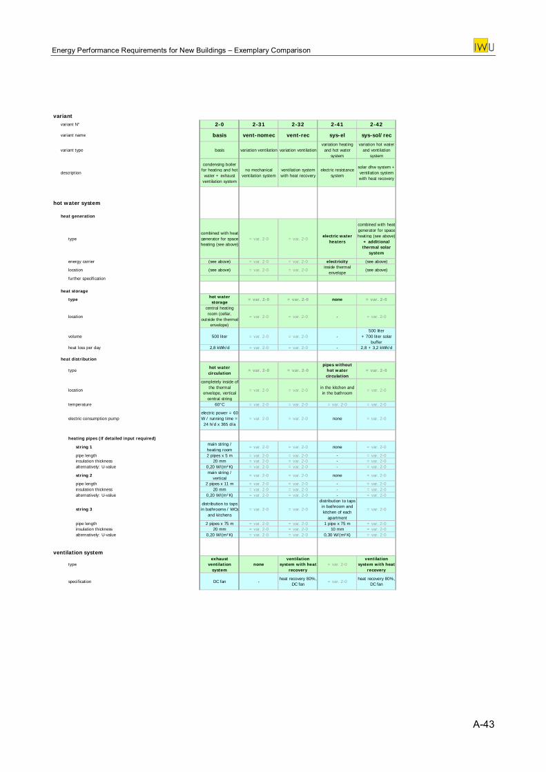
Energy Performance Requirements for New Buildings – Exemplary Comparison
variant
variant N° 2-0 2-31 2-32 2-41 2-42
variant name basis vent-nomec vent-rec sys-el sys-sol/rec
variant type basis variation ventilation variation ventilationvariation heating and hot water
system
variation hot water and ventilation
system
description
condensing boiler for heating and hot water + exhaust
ventilation system
no mechanical ventilation system
ventilation system with heat recovery
electric resistance system
solar dhw system + ventilation system with heat recovery
hot water system
heat generation
typecombined with heat generator for space heating (see above)
= var. 2-0 = var. 2-0electric water
heaters
combined with heat generator for space heating (see above)
+ additional thermal solar
system
energy carrier (see above) = var. 2-0 = var. 2-0 electricity (see above)
location (see above) = var. 2-0 = var. 2-0inside thermal
envelope(see above)
further specification
heat storage
type hot water storage
= var. 2-0 = var. 2-0 none = var. 2-0
location
central heating room (cellar,
outside the thermal envelope)
= var. 2-0 = var. 2-0 - = var. 2-0
volume 500 liter = var. 2-0 = var. 2-0 -500 liter
+ 700 liter solar buffer
heat loss per day 2,8 kWh/d = var. 2-0 = var. 2-0 - 2,8 + 3,2 kWh
heat distribution
typehot water circulation
= var. 2-0 = var. 2-0pipes without
hot water circulation
= var. 2-0
location
completely inside of the thermal
envelope, vertical central string
= var. 2-0 = var. 2-0 in the kitchen and in the bathroom
= var. 2-0
temperature 60°C = var. 2-0 = var. 2-0 = var. 2-0 = var. 2-0
electric consumption pumpelectric power = 60 W / runnin
/d
g time = 24 h/d x 365 d/a
= var. 2-0 = var. 2-0 none = var. 2-0
heating pipes (if detailed input required)
string 1main string / heating room
= var. 2-0 = var. 2-0 none = var. 2-0
pipe length 2 pipes x 5 m = var. 2-0 = var. 2-0 - = var. 2-0insulation thickness 20 mm = var. 2-0 = var. 2-0 - = var. 2-0alternatively: U-value 0,20 W/(m²K) = var. 2-0 = var. 2-0 - = var. 2-0
string 2main string /
vertical= var. 2-0 = var. 2-0 none = var. 2-0
pipe length 2 pipes x 11 m = var. 2-0 = var. 2-0 - = var. 2-0insulation thickness 20 mm = var. 2-0 = var. 2-0 - = var. 2-0alternatively: U-value 0,20 W/(m²K) = var. 2-0 = var. 2-0 - = var. 2-0
string 3distribution to taps in bathrooms / WCs
and kitchens= var. 2-0 = var. 2-0
distribution to taps in bathroom and kitchen of each
apartment
= var. 2-0
pipe length 2 pipes x 75 m = var. 2-0 = var. 2-0 1 pipe x 75 m = var. 2-0insulation thickness 20 mm = var. 2-0 = var. 2-0 10 mm = var. 2-0alternatively: U-value 0,20 W/(m²K) = var. 2-0 = var. 2-0 0,30 W/(m²K) = var. 2-0
ventilation system
typeexhaust
ventilation system
noneventilation
system with heat recovery
= var. 2-0ventilation
system with heat recovery
specification DC fan -heat recovery 80%,
DC fan = var. 2-0heat recovery 80%,
DC fan
A-43
Energy Performance Requirements for New Buildings – Exemplary Comparison
Appendix 2d: Country sheets
A-44
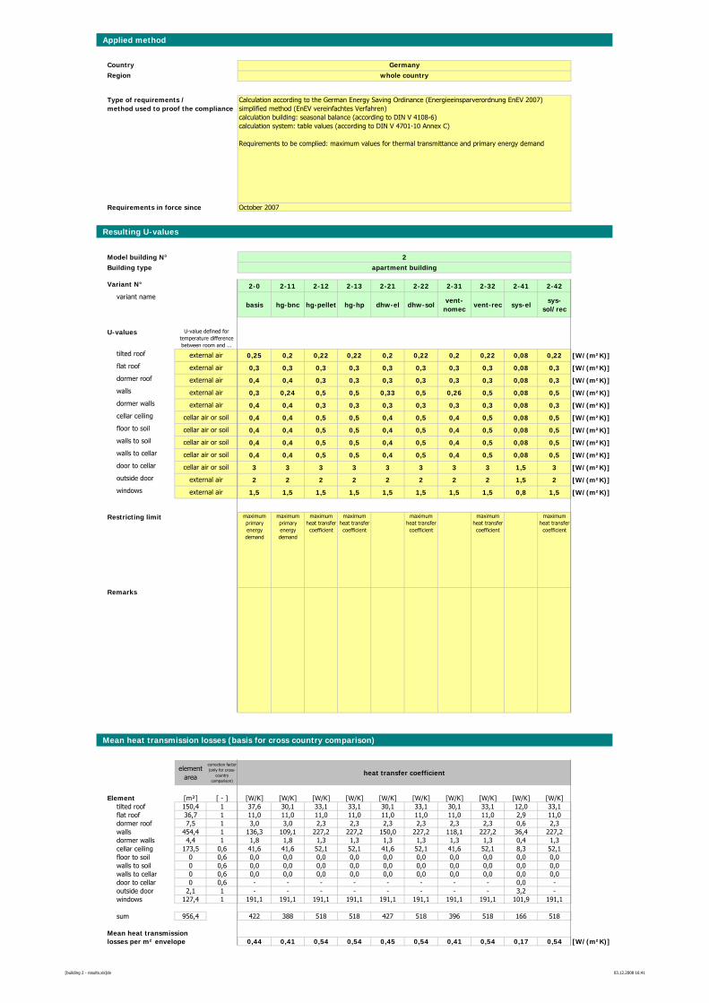
Applied method
CountryRegion
Requirements in force since
Resulting U-values
Model building N° 2Building type apartment building
Variant N° 2-0 2-11 2-12 2-13 2-21 2-22 2-31 2-32 2-41 2-42variant name
basis hg-bnc hg-pellet hg-hp dhw-el dhw-solvent-
nomecvent-rec sys-el
sys-sol/rec
U-values
tilted roof 0,25 0,2 0,22 0,22 0,2 0,22 0,2 0,22 0,08 0,22 [W/(m²K)]flat roof 0,3 0,3 0,3 0,3 0,3 0,3 0,3 0,3 0,08 0,3 [W/(m²K)]dormer roof 0,4 0,4 0,3 0,3 0,3 0,3 0,3 0,3 0,08 0,3 [W/(m²K)]walls 0,3 0,24 0,5 0,5 0,33 0,5 0,26 0,5 0,08 0,5 [W/(m²K)]dormer walls 0,4 0,4 0,3 0,3 0,3 0,3 0,3 0,3 0,08 0,3 [W/(m²K)]cellar ceiling 0,4 0,4 0,5 0,5 0,4 0,5 0,4 0,5 0,08 0,5 [W/(m²K)]floor to soil 0,4 0,4 0,5 0,5 0,4 0,5 0,4 0,5 0,08 0,5 [W/(m²K)]walls to soil 0,4 0,4 0,5 0,5 0,4 0,5 0,4 0,5 0,08 0,5 [W/(m²K)]walls to cellar 0,4 0,4 0,5 0,5 0,4 0,5 0,4 0,5 0,08 0,5 [W/(m²K)]door to cellar 3 3 3 3 3 3 3 3 1,5 3 [W/(m²K)]outside door 2 2 2 2 2 2 2 2 1,5 2 [W/(m²K)]windows 1,5 1,5 1,5 1,5 1,5 1,5 1,5 1,5 0,8 1,5 [W/(m²K)]
Restricting limit maximum primary energy demand
maximum primary energy demand
maximum heat transfer coefficient
maximum heat transfer coefficient
maximum heat transfer coefficient
maximum heat transfer coefficient
maximum heat transfer coefficient
Remarks
Mean heat transmission losses (basis for cross country comparison)
element area
correction factor (only for cross-
country comparison)
heat transfer coefficient
Element [m²] [ - ] [W/K] [W/K] [W/K] [W/K] [W/K] [W/K] [W/K] [W/K] [W/K] [W/K]tilted roof 150,4 1 37,6 30,1 33,1 33,1 30,1 33,1 30,1 33,1 12,0 33,1flat roof 36,7 1 11,0 11,0 11,0 11,0 11,0 11,0 11,0 11,0 2,9 11,0dormer roof 7,5 1 3,0 3,0 2,3 2,3 2,3 2,3 2,3 2,3 0,6 2,3walls 454,4 1 136,3 109,1 227,2 227,2 150,0 227,2 118,1 227,2 36,4 227,2dormer walls 4,4 1 1,8 1,8 1,3 1,3 1,3 1,3 1,3 1,3 0,4 1,3cellar ceiling 173,5 0,6 41,6 41,6 52,1 52,1 41,6 52,1 41,6 52,1 8,3 52,1floor to soil 0 0,6 0,0 0,0 0,0 0,0 0,0 0,0 0,0 0,0 0,0 0,0walls to soil 0 0,6 0,0 0,0 0,0 0,0 0,0 0,0 0,0 0,0 0,0 0,0walls to cellar 0 0,6 0,0 0,0 0,0 0,0 0,0 0,0 0,0 0,0 0,0 0,0door to cellar 0 0,6 - - - - - - - - 0,0 -outside door 2,1 1 - - - - - - - - 3,2 -windows 127,4 1 191,1 191,1 191,1 191,1 191,1 191,1 191,1 191,1 101,9 191,1
sum 956,4 422 388 518 518 427 518 396 518 166 518
Mean heat transmissionlosses per m² envelope 0,44 0,41 0,54 0,54 0,45 0,54 0,41 0,54 0,17 0,54 [W/(m²K)]
cellar air or soil
external air
Calculation according to the German Energy Saving Ordinance (Energieeinsparverordnung EnEV 2007)simplified method (EnEV vereinfachtes Verfahren)calculation building: seasonal balance (according to DIN V 4108-6)calculation system: table values (according to DIN V 4701-10 Annex C)
Requirements to be complied: maximum values for thermal transmittance and primary energy demand
Germanywhole country
U-value defined for temperature difference between room and ...
Type of requirements / method used to proof the compliance
October 2007
external air
external air
external air
external air
external air
external air
cellar air or soil
cellar air or soil
cellar air or soil
cellar air or soil
[building 2 - results.xls]de 03.12.2008 16:41
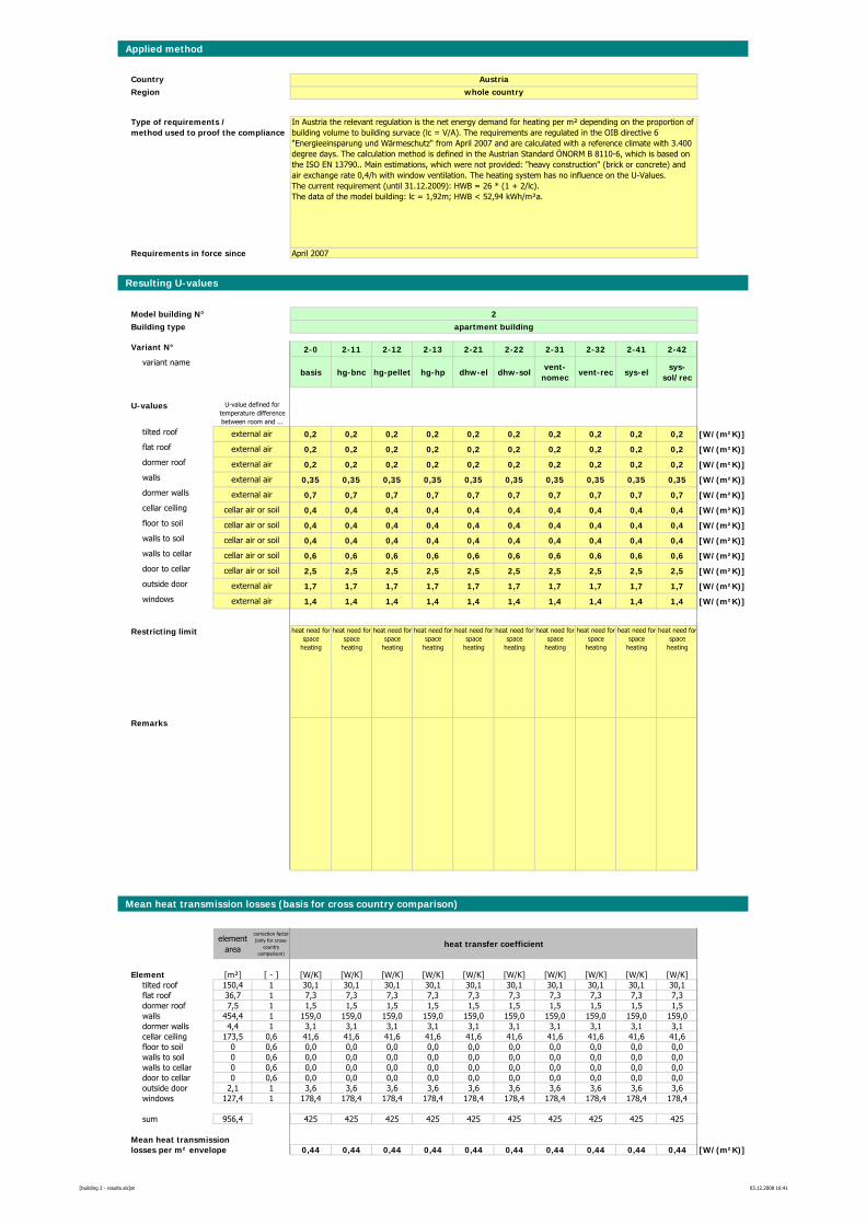
Applied method
CountryRegion
Requirements in force since
Resulting U-values
Model building N° 2Building type apartment building
Variant N° 2-0 2-11 2-12 2-13 2-21 2-22 2-31 2-32 2-41 2-42variant name
basis hg-bnc hg-pellet hg-hp dhw-el dhw-solvent-
nomecvent-rec sys-el
sys-sol/rec
U-values
tilted roof 0,2 0,2 0,2 0,2 0,2 0,2 0,2 0,2 0,2 0,2 [W/(m²K)]flat roof 0,2 0,2 0,2 0,2 0,2 0,2 0,2 0,2 0,2 0,2 [W/(m²K)]dormer roof 0,2 0,2 0,2 0,2 0,2 0,2 0,2 0,2 0,2 0,2 [W/(m²K)]walls 0,35 0,35 0,35 0,35 0,35 0,35 0,35 0,35 0,35 0,35 [W/(m²K)]dormer walls 0,7 0,7 0,7 0,7 0,7 0,7 0,7 0,7 0,7 0,7 [W/(m²K)]cellar ceiling 0,4 0,4 0,4 0,4 0,4 0,4 0,4 0,4 0,4 0,4 [W/(m²K)]floor to soil 0,4 0,4 0,4 0,4 0,4 0,4 0,4 0,4 0,4 0,4 [W/(m²K)]walls to soil 0,4 0,4 0,4 0,4 0,4 0,4 0,4 0,4 0,4 0,4 [W/(m²K)]walls to cellar 0,6 0,6 0,6 0,6 0,6 0,6 0,6 0,6 0,6 0,6 [W/(m²K)]door to cellar 2,5 2,5 2,5 2,5 2,5 2,5 2,5 2,5 2,5 2,5 [W/(m²K)]outside door 1,7 1,7 1,7 1,7 1,7 1,7 1,7 1,7 1,7 1,7 [W/(m²K)]windows 1,4 1,4 1,4 1,4 1,4 1,4 1,4 1,4 1,4 1,4 [W/(m²K)]
Restricting limit heat need for space
heating
heat need for space
heating
heat need for space
heating
heat need for space
heating
heat need for space
heating
heat need for space
heating
heat need for space
heating
heat need for space
heating
heat need for space
heating
heat need for space
heating
Remarks
Mean heat transmission losses (basis for cross country comparison)
element area
correction factor (only for cross-
country comparison)
heat transfer coefficient
Element [m²] [ - ] [W/K] [W/K] [W/K] [W/K] [W/K] [W/K] [W/K] [W/K] [W/K] [W/K]tilted roof 150,4 1 30,1 30,1 30,1 30,1 30,1 30,1 30,1 30,1 30,1 30,1flat roof 36,7 1 7,3 7,3 7,3 7,3 7,3 7,3 7,3 7,3 7,3 7,3dormer roof 7,5 1 1,5 1,5 1,5 1,5 1,5 1,5 1,5 1,5 1,5 1,5walls 454,4 1 159,0 159,0 159,0 159,0 159,0 159,0 159,0 159,0 159,0 159,0dormer walls 4,4 1 3,1 3,1 3,1 3,1 3,1 3,1 3,1 3,1 3,1 3,1cellar ceiling 173,5 0,6 41,6 41,6 41,6 41,6 41,6 41,6 41,6 41,6 41,6 41,6floor to soil 0 0,6 0,0 0,0 0,0 0,0 0,0 0,0 0,0 0,0 0,0 0,0walls to soil 0 0,6 0,0 0,0 0,0 0,0 0,0 0,0 0,0 0,0 0,0 0,0walls to cellar 0 0,6 0,0 0,0 0,0 0,0 0,0 0,0 0,0 0,0 0,0 0,0door to cellar 0 0,6 0,0 0,0 0,0 0,0 0,0 0,0 0,0 0,0 0,0 0,0outside door 2,1 1 3,6 3,6 3,6 3,6 3,6 3,6 3,6 3,6 3,6 3,6windows 127,4 1 178,4 178,4 178,4 178,4 178,4 178,4 178,4 178,4 178,4 178,4
sum 956,4 425 425 425 425 425 425 425 425 425 425
Mean heat transmissionlosses per m² envelope 0,44 0,44 0,44 0,44 0,44 0,44 0,44 0,44 0,44 0,44 [W/(m²K)]
external air
external air
external air
external air
external air
external air
cellar air or soil
cellar air or soil
cellar air or soil
cellar air or soil
cellar air or soil
external air
In Austria the relevant regulation is the net energy demand for heating per m² depending on the proportion of building volume to building survace (lc = V/A). The requirements are regulated in the OIB directive 6 "Energieeinsparung und Wärmeschutz" from April 2007 and are calculated with a reference climate with 3.400 degree days. The calculation method is defined in the Austrian Standard ÖNORM B 8110-6, which is based on the ISO EN 13790.. Main estimations, which were not provided: "heavy construction" (brick or concrete) and air exchange rate 0,4/h with window ventilation. The heating system has no influence on the U-Values.The current requirement (until 31.12.2009): HWB = 26 * (1 + 2/lc). The data of the model building: lc = 1,92m; HWB < 52,94 kWh/m²a.
Austriawhole country
U-value defined for temperature difference between room and ...
Type of requirements / method used to proof the compliance
April 2007
[building 2 - results.xls]at 03.12.2008 16:41
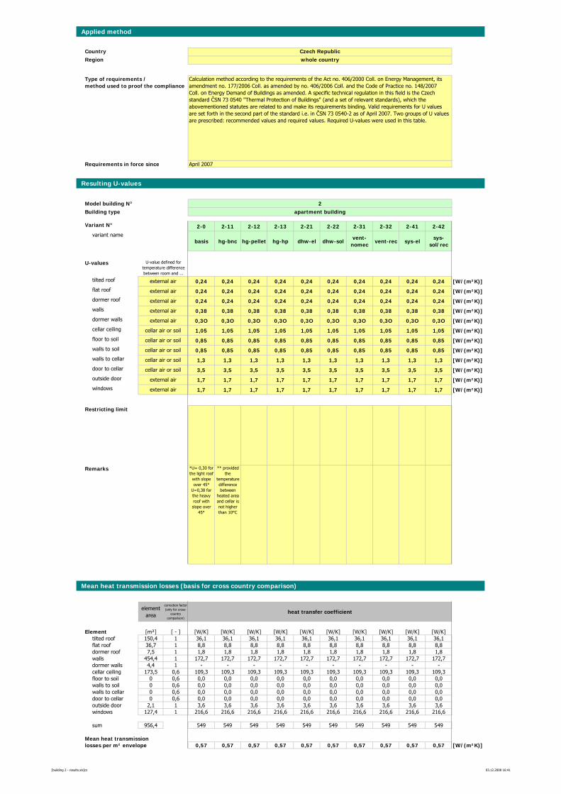
Applied method
CountryRegion
Requirements in force since
Resulting U-values
Model building N° 2Building type apartment building
Variant N° 2-0 2-11 2-12 2-13 2-21 2-22 2-31 2-32 2-41 2-42variant name
basis hg-bnc hg-pellet hg-hp dhw-el dhw-solvent-
nomecvent-rec sys-el
sys-sol/rec
U-values
tilted roof 0,24 0,24 0,24 0,24 0,24 0,24 0,24 0,24 0,24 0,24 [W/(m²K)]flat roof 0,24 0,24 0,24 0,24 0,24 0,24 0,24 0,24 0,24 0,24 [W/(m²K)]dormer roof 0,24 0,24 0,24 0,24 0,24 0,24 0,24 0,24 0,24 0,24 [W/(m²K)]walls 0,38 0,38 0,38 0,38 0,38 0,38 0,38 0,38 0,38 0,38 [W/(m²K)]dormer walls 0,3O 0,3O 0,3O 0,3O 0,3O 0,3O 0,3O 0,3O 0,3O 0,3O [W/(m²K)]cellar ceiling 1,05 1,05 1,05 1,05 1,05 1,05 1,05 1,05 1,05 1,05 [W/(m²K)]floor to soil 0,85 0,85 0,85 0,85 0,85 0,85 0,85 0,85 0,85 0,85 [W/(m²K)]walls to soil 0,85 0,85 0,85 0,85 0,85 0,85 0,85 0,85 0,85 0,85 [W/(m²K)]walls to cellar 1,3 1,3 1,3 1,3 1,3 1,3 1,3 1,3 1,3 1,3 [W/(m²K)]door to cellar 3,5 3,5 3,5 3,5 3,5 3,5 3,5 3,5 3,5 3,5 [W/(m²K)]outside door 1,7 1,7 1,7 1,7 1,7 1,7 1,7 1,7 1,7 1,7 [W/(m²K)]windows 1,7 1,7 1,7 1,7 1,7 1,7 1,7 1,7 1,7 1,7 [W/(m²K)]
Restricting limit
Remarks *U= 0,30 for the light roof with slope over 45°
U=0,38 for the heavy roof with slope over
45°
** provided the
temperature difference between
heated area and cellar is not higher than 10°C
Mean heat transmission losses (basis for cross country comparison)
element area
correction factor (only for cross-
country comparison)
heat transfer coefficient
Element [m²] [ - ] [W/K] [W/K] [W/K] [W/K] [W/K] [W/K] [W/K] [W/K] [W/K] [W/K]tilted roof 150,4 1 36,1 36,1 36,1 36,1 36,1 36,1 36,1 36,1 36,1 36,1flat roof 36,7 1 8,8 8,8 8,8 8,8 8,8 8,8 8,8 8,8 8,8 8,8dormer roof 7,5 1 1,8 1,8 1,8 1,8 1,8 1,8 1,8 1,8 1,8 1,8walls 454,4 1 172,7 172,7 172,7 172,7 172,7 172,7 172,7 172,7 172,7 172,7dormer walls 4,4 1 - - - - - - - - - -cellar ceiling 173,5 0,6 109,3 109,3 109,3 109,3 109,3 109,3 109,3 109,3 109,3 109,3floor to soil 0 0,6 0,0 0,0 0,0 0,0 0,0 0,0 0,0 0,0 0,0 0,0walls to soil 0 0,6 0,0 0,0 0,0 0,0 0,0 0,0 0,0 0,0 0,0 0,0walls to cellar 0 0,6 0,0 0,0 0,0 0,0 0,0 0,0 0,0 0,0 0,0 0,0door to cellar 0 0,6 0,0 0,0 0,0 0,0 0,0 0,0 0,0 0,0 0,0 0,0outside door 2,1 1 3,6 3,6 3,6 3,6 3,6 3,6 3,6 3,6 3,6 3,6windows 127,4 1 216,6 216,6 216,6 216,6 216,6 216,6 216,6 216,6 216,6 216,6
sum 956,4 549 549 549 549 549 549 549 549 549 549
Mean heat transmissionlosses per m² envelope 0,57 0,57 0,57 0,57 0,57 0,57 0,57 0,57 0,57 0,57 [W/(m²K)]
cellar air or soil
external air
Calculation method according to the requirements of the Act no. 406/2000 Coll. on Energy Management, its amendment no. 177/2006 Coll. as amended by no. 406/2006 Coll. and the Code of Practice no. 148/2007Coll. on Energy Demand of Buildings as amended. A specific technical regulation in this field is the Czech standard ČSN 73 0540 "Thermal Protection of Buildings" (and a set of relevant standards), which the abovementioned statutes are related to and make its requirements binding. Valid requirements for U values are set forth in the second part of the standard i.e. in ČSN 73 0540-2 as of April 2007. Two groups of U values are prescribed: recommended values and required values. Required U-values were used in this table.
Czech Republicwhole country
U-value defined for temperature difference between room and ...
Type of requirements / method used to proof the compliance
April 2007
external air
external air
external air
external air
external air
external air
cellar air or soil
cellar air or soil
cellar air or soil
cellar air or soil
[building 2 - results.xls]cz 03.12.2008 16:41
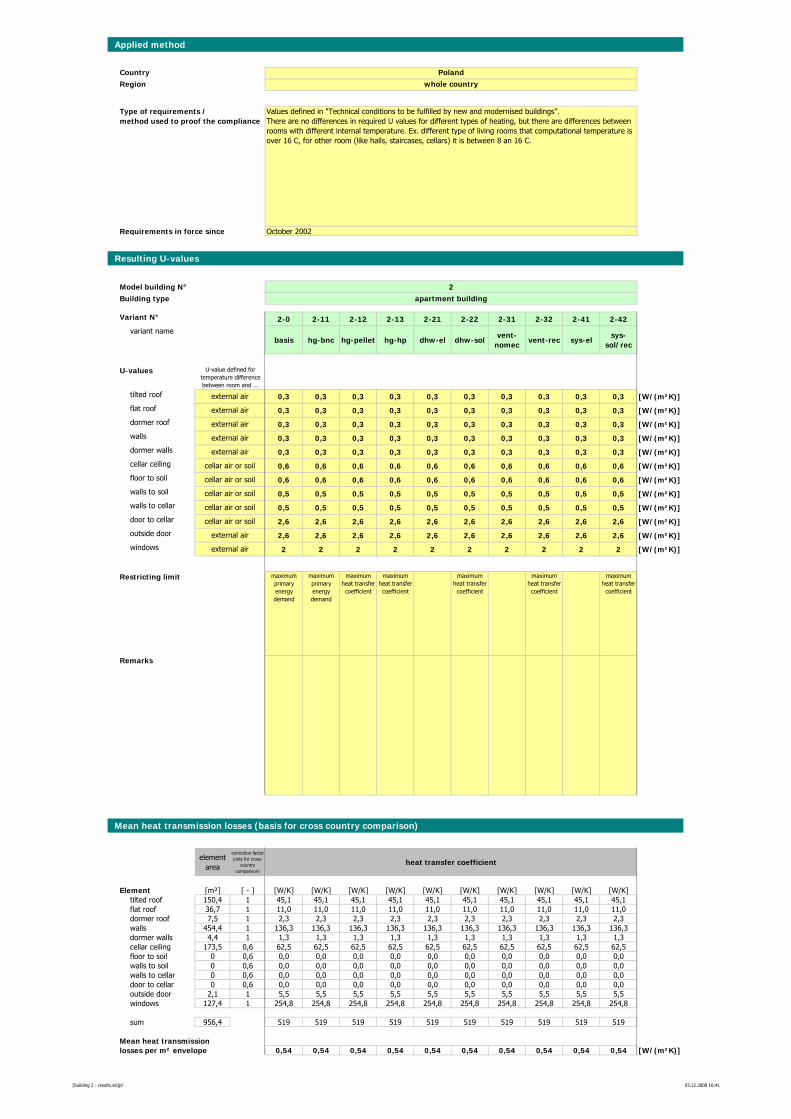
Applied method
CountryRegion
Requirements in force since
Resulting U-values
Model building N° 2Building type apartment building
Variant N° 2-0 2-11 2-12 2-13 2-21 2-22 2-31 2-32 2-41 2-42variant name
basis hg-bnc hg-pellet hg-hp dhw-el dhw-solvent-
nomecvent-rec sys-el
sys-sol/rec
U-values
tilted roof 0,3 0,3 0,3 0,3 0,3 0,3 0,3 0,3 0,3 0,3 [W/(m²K)]flat roof 0,3 0,3 0,3 0,3 0,3 0,3 0,3 0,3 0,3 0,3 [W/(m²K)]dormer roof 0,3 0,3 0,3 0,3 0,3 0,3 0,3 0,3 0,3 0,3 [W/(m²K)]walls 0,3 0,3 0,3 0,3 0,3 0,3 0,3 0,3 0,3 0,3 [W/(m²K)]dormer walls 0,3 0,3 0,3 0,3 0,3 0,3 0,3 0,3 0,3 0,3 [W/(m²K)]cellar ceiling 0,6 0,6 0,6 0,6 0,6 0,6 0,6 0,6 0,6 0,6 [W/(m²K)]floor to soil 0,6 0,6 0,6 0,6 0,6 0,6 0,6 0,6 0,6 0,6 [W/(m²K)]walls to soil 0,5 0,5 0,5 0,5 0,5 0,5 0,5 0,5 0,5 0,5 [W/(m²K)]walls to cellar 0,5 0,5 0,5 0,5 0,5 0,5 0,5 0,5 0,5 0,5 [W/(m²K)]door to cellar 2,6 2,6 2,6 2,6 2,6 2,6 2,6 2,6 2,6 2,6 [W/(m²K)]outside door 2,6 2,6 2,6 2,6 2,6 2,6 2,6 2,6 2,6 2,6 [W/(m²K)]windows 2 2 2 2 2 2 2 2 2 2 [W/(m²K)]
Restricting limit maximum primary energy demand
maximum primary energy demand
maximum heat transfer coefficient
maximum heat transfer coefficient
maximum heat transfer coefficient
maximum heat transfer coefficient
maximum heat transfer coefficient
Remarks
Mean heat transmission losses (basis for cross country comparison)
element area
correction factor (only for cross-
country comparison)
heat transfer coefficient
Element [m²] [ - ] [W/K] [W/K] [W/K] [W/K] [W/K] [W/K] [W/K] [W/K] [W/K] [W/K]tilted roof 150,4 1 45,1 45,1 45,1 45,1 45,1 45,1 45,1 45,1 45,1 45,1flat roof 36,7 1 11,0 11,0 11,0 11,0 11,0 11,0 11,0 11,0 11,0 11,0dormer roof 7,5 1 2,3 2,3 2,3 2,3 2,3 2,3 2,3 2,3 2,3 2,3walls 454,4 1 136,3 136,3 136,3 136,3 136,3 136,3 136,3 136,3 136,3 136,3dormer walls 4,4 1 1,3 1,3 1,3 1,3 1,3 1,3 1,3 1,3 1,3 1,3cellar ceiling 173,5 0,6 62,5 62,5 62,5 62,5 62,5 62,5 62,5 62,5 62,5 62,5floor to soil 0 0,6 0,0 0,0 0,0 0,0 0,0 0,0 0,0 0,0 0,0 0,0walls to soil 0 0,6 0,0 0,0 0,0 0,0 0,0 0,0 0,0 0,0 0,0 0,0walls to cellar 0 0,6 0,0 0,0 0,0 0,0 0,0 0,0 0,0 0,0 0,0 0,0door to cellar 0 0,6 0,0 0,0 0,0 0,0 0,0 0,0 0,0 0,0 0,0 0,0outside door 2,1 1 5,5 5,5 5,5 5,5 5,5 5,5 5,5 5,5 5,5 5,5windows 127,4 1 254,8 254,8 254,8 254,8 254,8 254,8 254,8 254,8 254,8 254,8
sum 956,4 519 519 519 519 519 519 519 519 519 519
Mean heat transmissionlosses per m² envelope 0,54 0,54 0,54 0,54 0,54 0,54 0,54 0,54 0,54 0,54 [W/(m²K)]
external air
external air
external air
external air
external air
external air
cellar air or soil
cellar air or soil
cellar air or soil
cellar air or soil
cellar air or soil
external air
Values defined in "Technical conditions to be fulfilled by new and modernised buildings”. There are no differences in required U values for different types of heating, but there are differences between rooms with different internal temperature. Ex. different type of living rooms that computational temperature is over 16 C, for other room (like halls, staircases, cellars) it is between 8 an 16 C.
Polandwhole country
U-value defined for temperature difference between room and ...
Type of requirements / method used to proof the compliance
October 2002
[building 2 - results.xls]pl 03.12.2008 16:41
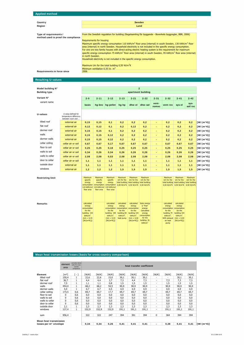
Applied method
CountryRegion
Requirements in force since
Resulting U-values
Model building N° 2Building type apartment building
Variant N° 2-0 2-11 2-12 2-13 2-21 2-22 2-31 2-32 2-41 2-42variant name
basis hg-bnc hg-pellet hg-hp dhw-el dhw-solvent-
nomecvent-rec sys-el
sys-sol/rec
U-values
tilted roof 0,15 0,15 0,1 0,2 0,2 0,2 - 0,2 0,2 0,2 [W/(m²K)]flat roof 0,12 0,12 0,1 0,2 0,12 0,2 - 0,2 0,2 0,2 [W/(m²K)]dormer roof 0,15 0,15 0,1 0,2 0,2 0,2 - 0,2 0,2 0,2 [W/(m²K)]walls 0,15 0,15 0,12 0,2 0,2 0,2 - 0,2 0,2 0,2 [W/(m²K)]dormer walls 0,15 0,15 0,12 0,2 0,2 0,2 - 0,2 0,2 0,2 [W/(m²K)]cellar ceiling 0,67 0,67 0,17 0,67 0,67 0,67 - 0,67 0,67 0,67 [W/(m²K)]floor to soil 0,25 0,25 0,18 0,25 0,25 0,25 - 0,25 0,25 0,25 [W/(m²K)]walls to soil 0,34 0,26 0,34 0,26 0,26 0,26 - 0,26 0,26 0,26 [W/(m²K)]walls to cellar 2,08 2,08 0,53 2,08 2,08 2,08 - 2,08 2,08 2,08 [W/(m²K)]door to cellar 1,1 1,1 1,1 1,1 1,1 1,1 - 1,1 1,1 1,1 [W/(m²K)]outside door 1,1 1,1 1,1 1,1 1,1 1,1 - 1,1 1,1 1,1 [W/(m²K)]windows 1,2 1,2 1,2 1,5 1,5 1,5 - 1,5 1,5 1,5 [W/(m²K)]
Restricting limit Maximum specific energy
consumption 110 kWh/m2
floor area
Maximum specific energy
consumption 110 kWh/m2
floor area
Maximum specific energy
consumption 110 kWh/m2
floor area
Maximum Um for the
total building 0,50 W/m2K
Maximum Um for the
total building 0,50 W/m2K
Maximum Um for the
total building 0,50 W/m2K
Maximum Um for the
total building 0,50 W/m2K
Maximum Um for the
total building 0,50 W/m2K
Maximum Um for the
total building 0,50 W/m2K
Remarks calculated energy
consumption for the
building 103 kWh/m2.
(Um = 0,43 [W/(m²K)])
calculated energy
consumption for the
building 109 kWh/m2.
(Um = 0,43 [W/(m²K)])
calculated energy
consumption for the
building 69 kWh/m2.
heat pump
calculated energy
consumption for the
building 104 kWh/m2.
(Um = 0,50 [W/(m²K)])
Solar energy is "free" energy.
Calculated energy
consumption for the
building 81 kWh/m2.
calculated energy
consumption for the
building 79 kWh/m2.
With exhaust air heat pump
calculated energy
consumption for the
building 104 kWh/m2.
(Um = 0,50 [W/(m²K)])
Mean heat transmission losses (basis for cross country comparison)
element area
correction factor (only for cross-
country comparison)
heat transfer coefficient
Element [m²] [ - ] [W/K] [W/K] [W/K] [W/K] [W/K] [W/K] [W/K] [W/K] [W/K] [W/K]tilted roof 150,4 1 22,6 22,6 15,0 30,1 30,1 30,1 - - 30,1 30,1flat roof 36,7 1 4,4 4,4 3,7 7,3 4,4 7,3 - 7,3 7,3 7,3dormer roof 7,5 1 1,1 1,1 0,8 1,5 1,5 1,5 - 1,5 1,5 1,5walls 454,4 1 68,2 68,2 54,5 90,9 90,9 90,9 - 90,9 90,9 90,9dormer walls 4,4 1 0,7 0,7 0,5 0,9 0,9 0,9 - 0,9 0,9 0,9cellar ceiling 173,5 0,6 69,7 69,7 17,7 69,7 69,7 69,7 - 69,7 69,7 69,7floor to soil 0 0,6 0,0 0,0 0,0 0,0 0,0 0,0 - 0,0 0,0 0,0walls to soil 0 0,6 0,0 0,0 0,0 0,0 0,0 0,0 - 0,0 0,0 0,0walls to cellar 0 0,6 0,0 0,0 0,0 0,0 0,0 0,0 - 0,0 0,0 0,0door to cellar 0 0,6 0,0 0,0 0,0 0,0 0,0 0,0 - 0,0 0,0 0,0outside door 2,1 1 2,3 2,3 2,3 2,3 2,3 2,3 - 2,3 2,3 2,3windows 127,4 1 152,9 152,9 152,9 191,1 191,1 191,1 - 191,1 191,1 191,1
sum 956,4 322 322 247 394 391 394 0 364 394 394
Mean heat transmissionlosses per m² envelope 0,34 0,34 0,26 0,41 0,41 0,41 - 0,38 0,41 0,41 [W/(m²K)]
external air
external air
external air
external air
external air
external air
cellar air or soil
cellar air or soil
cellar air or soil
cellar air or soil
cellar air or soil
external air
From the Swedish regulation for building (Regelsamling för byggande - Boverkets byggregler, BBR, 2006)
Requirements for housing Maximum specific energy consumption 110 kWh/m2 floor area (internal) in south Sweden, 130 kWh/m2 floor area (internal) in north Sweden. Household electricity is not included in the specific energy consumption.For one ore two family houses with direct-acting electric heating system is the requirement for maximum specific energy consumption 75 kWh/m2 floor area (internal) in south Sweden, 95 kWh/m2 floor area (internal) in north Sweden.Household electricity is not included in the specific energy consumption.
Maximum Um for the total building 0,50 W/m2KMinimum ventilation 0,35 l/s m2
SwedenLund
U-value defined for temperature difference between room and ...
Type of requirements / method used to proof the compliance
2006
[building 2 - results.xls]se 03.12.2008 16:41
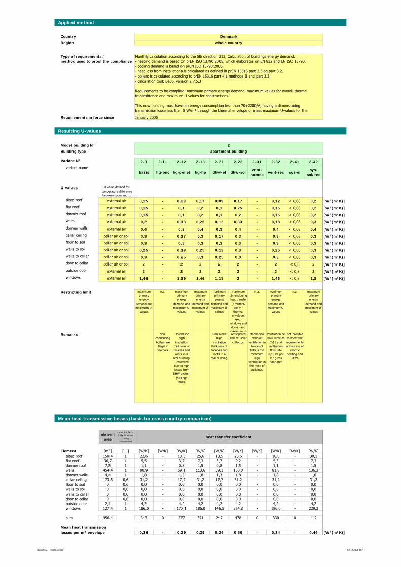
Applied method
CountryRegion
Requirements in force since
Resulting U-values
Model building N° 2Building type apartment building
Variant N° 2-0 2-11 2-12 2-13 2-21 2-22 2-31 2-32 2-41 2-42variant name
basis hg-bnc hg-pellet hg-hp dhw-el dhw-solvent-
nomecvent-rec sys-el
sys-sol/rec
U-values
tilted roof 0,15 - 0,09 0,17 0,09 0,17 - 0,12 < 0,08 0,2 [W/(m²K)]flat roof 0,15 - 0,1 0,2 0,1 0,25 - 0,15 < 0,08 0,2 [W/(m²K)]dormer roof 0,15 - 0,1 0,2 0,1 0,2 - 0,15 < 0,08 0,2 [W/(m²K)]walls 0,2 - 0,13 0,25 0,13 0,33 - 0,18 < 0,08 0,3 [W/(m²K)]dormer walls 0,4 - 0,3 0,4 0,3 0,4 - 0,4 < 0,08 0,4 [W/(m²K)]cellar ceiling 0,3 - 0,17 0,3 0,17 0,3 - 0,3 < 0,08 0,3 [W/(m²K)]floor to soil 0,3 - 0,3 0,3 0,3 0,3 - 0,3 < 0,08 0,3 [W/(m²K)]walls to soil 0,25 - 0,19 0,25 0,19 0,3 - 0,25 < 0,08 0,3 [W/(m²K)]walls to cellar 0,3 - 0,25 0,3 0,25 0,3 - 0,3 < 0,08 0,3 [W/(m²K)]door to cellar 2 - 2 2 2 2 - 2 < 0,8 2 [W/(m²K)]outside door 2 - 2 2 2 2 - 2 < 0,8 2 [W/(m²K)]windows 1,46 - 1,39 1,46 1,15 2 - 1,46 < 0,8 1,8 [W/(m²K)]
Restricting limit maximum primary energy
demand and maximum U-
values
n.a. maximum primary energy
demand and maximum U-
values
maximum primary energy
demand and maximum U-
values
maximum primary energy
demand and maximum U-
values
maximum dimensioning heat transfer (8 W/m²K
per m² thermal
envelope, excl.
windows and doors) and
maximum U-
n.a. maximum primary energy
demand and maximum U-
values
n.a. maximum primary energy
demand and maximum U-
values
Remarks Non-condensing boilers are illegal in
Denmark.
Unrealistic high
insulation thickness of facades and roofs in a
real building. Resuested due to high losses from
DHW system (storage tank).
Unrealistic high
insulation thickness of facades and roofs in a
real building.
Anticipated 100 m² solar
collector.
Mechanical exhauxt
ventilation in blocks of
flats is the minimum
legal ventilation in this type of buildings.
Ventilation airflow same as
2-11 and infiltration flow rate
0,13 l/s per m² gross floor area
Not possible to meet the
requirements in the case of
electric heating and
DHW.
Mean heat transmission losses (basis for cross country comparison)
element area
correction factor (only for cross-
country comparison)
heat transfer coefficient
Element [m²] [ - ] [W/K] [W/K] [W/K] [W/K] [W/K] [W/K] [W/K] [W/K] [W/K] [W/K]tilted roof 150,4 1 22,6 - 13,5 25,6 13,5 25,6 - 18,0 - 30,1flat roof 36,7 1 5,5 - 3,7 7,3 3,7 9,2 - 5,5 - 7,3dormer roof 7,5 1 1,1 - 0,8 1,5 0,8 1,5 - 1,1 - 1,5walls 454,4 1 90,9 - 59,1 113,6 59,1 150,0 - 81,8 - 136,3dormer walls 4,4 1 1,8 - 1,3 1,8 1,3 1,8 - 1,8 - 1,8cellar ceiling 173,5 0,6 31,2 - 17,7 31,2 17,7 31,2 - 31,2 - 31,2floor to soil 0 0,6 0,0 - 0,0 0,0 0,0 0,0 - 0,0 - 0,0walls to soil 0 0,6 0,0 - 0,0 0,0 0,0 0,0 - 0,0 - 0,0walls to cellar 0 0,6 0,0 - 0,0 0,0 0,0 0,0 - 0,0 - 0,0door to cellar 0 0,6 0,0 - 0,0 0,0 0,0 0,0 - 0,0 - 0,0outside door 2,1 1 4,2 - 4,2 4,2 4,2 4,2 - 4,2 - 4,2windows 127,4 1 186,0 - 177,1 186,0 146,5 254,8 - 186,0 - 229,3
sum 956,4 343 0 277 371 247 478 0 330 0 442
Mean heat transmissionlosses per m² envelope 0,36 - 0,29 0,39 0,26 0,50 - 0,34 - 0,46 [W/(m²K)]
external air
external air
external air
external air
external air
external air
cellar air or soil
cellar air or soil
cellar air or soil
cellar air or soil
cellar air or soil
external air
Monthly calculation according to the SBi direction 213, Calculation of buildings energy demand. - heating demand is based on prEN ISO 13790:2005, which elaborates on EN 832 and EN ISO 13790.- cooling demand is based on prEN ISO 13790:2005.- heat loss from installations is calculated as defined in prEN 15316 part 2.3 og part 3.2.- boilers is calculated according to prEN 15316 part 4.1 methode II and part 3.3. - calculation tool: Be06, version 2,7,5,3
Requirements to be complied: maximum primary energy demand, maximum values for overall thermal transmittance and maximum U-values for constructions.
This new building must have an energy consumption less than 70+2200/A, having a dimensioning transmission losse less than 8 W/m² through the thermal envelope or meet maximum U-values for the
t ti
Denmarkwhole country
U-value defined for temperature difference between room and ...
Type of requirements / method used to proof the compliance
January 2006
[building 2 - results.xls]dk 03.12.2008 16:41
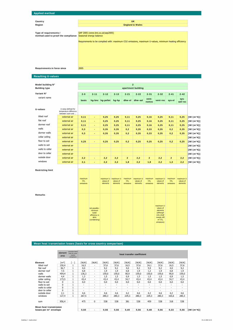
Applied method
CountryRegion
Requirements in force since
Resulting U-values
Model building N° 2Building type apartment building
Variant N° 2-0 2-11 2-12 2-13 2-21 2-22 2-31 2-32 2-41 2-42variant name
basis hg-bnc hg-pellet hg-hp dhw-el dhw-solvent-
nomecvent-rec sys-el
sys-sol/rec
U-values
tilted roof 0,11 - 0,25 0,25 0,11 0,25 0,16 0,25 0,11 0,25 [W/(m²K)]flat roof 0,11 - 0,25 0,25 0,11 0,25 0,16 0,25 0,11 0,25 [W/(m²K)]dormer roof 0,11 - 0,25 0,25 0,11 0,25 0,16 0,25 0,11 0,25 [W/(m²K)]walls 0,3 - 0,35 0,35 0,2 0,35 0,33 0,35 0,2 0,35 [W/(m²K)]dormer walls 0,3 - 0,35 0,35 0,2 0,35 0,33 0,35 0,2 0,35 [W/(m²K)]cellar ceiling 0,25 - 0,25 0,25 0,2 0,25 0,25 0,25 0,2 0,25 [W/(m²K)]floor to soil 0,25 - 0,25 0,25 0,2 0,25 0,25 0,25 0,2 0,25 [W/(m²K)]walls to soil [W/(m²K)]walls to cellar [W/(m²K)]door to cellar [W/(m²K)]outside door 2,2 - 2,2 2,2 2 2,2 2 2,2 2 2,2 [W/(m²K)]windows 2,1 - 2,2 2,2 1,8 2,2 1,8 2,2 1,3 2,2 [W/(m²K)]
Restricting limit
maximum CO2
emissions
maximum U-values of elements
maximum U-values of elements
maximum CO2
emissions
maximum U-values of elements
maximum CO2
emissions
maximum U-values of elements
maximum CO2
emissions
maximum U-values of elements
Remarks
not possible - minimum
boiler efficiency is
86% (condensing)
maximum U-values of elements (although only small margin left
on CO2
emissions)
Mean heat transmission losses (basis for cross country comparison)
element area
correction factor (only for cross-
country comparison)
heat transfer coefficient
Element [m²] [ - ] [W/K] [W/K] [W/K] [W/K] [W/K] [W/K] [W/K] [W/K] [W/K] [W/K]tilted roof 150,4 1 16,5 - 37,6 37,6 16,5 37,6 24,1 37,6 16,5 37,6flat roof 36,7 1 4,0 - 9,2 9,2 4,0 9,2 5,9 9,2 4,0 9,2dormer roof 7,5 1 0,8 - 1,9 1,9 0,8 1,9 1,2 1,9 0,8 1,9walls 454,4 1 136,3 - 159,0 159,0 90,9 159,0 150,0 159,0 90,9 159,0dormer walls 4,4 1 1,3 - 1,5 1,5 0,9 1,5 1,5 1,5 0,9 1,5cellar ceiling 173,5 1 43,4 - 43,4 43,4 34,7 43,4 43,4 43,4 34,7 43,4floor to soil 0 1 0,0 - 0,0 0,0 0,0 0,0 0,0 0,0 0,0 0,0walls to soil 0 1 - - - - - - - - - -walls to cellar 0 1 - - - - - - - - - -door to cellar 0 1 - - - - - - - - - -outside door 2,1 1 4,6 - 4,6 4,6 4,2 4,6 4,2 4,6 4,2 4,6windows 127,4 1 267,5 - 280,3 280,3 229,3 280,3 229,3 280,3 165,6 280,3
sum 956,4 475 0 538 538 381 538 459 538 318 538
Mean heat transmissionlosses per m² envelope 0,50 - 0,56 0,56 0,40 0,56 0,48 0,56 0,33 0,56 [W/(m²K)]
external air
external air
external air
external air
external air
external air
external air
external air
external air
external air
external air
external air
SAP 2005 (www.bre.co.uk/sap2005) Seasonal energy balance
Requirements to be complied with: maximum CO2 emissions, maximum U-values, minimum heating efficiency
UKEngland & Wales
U-value defined for temperature difference between room and ...
Type of requirements / method used to proof the compliance
2005
[building 2 - results.xls]uk 03.12.2008 16:41
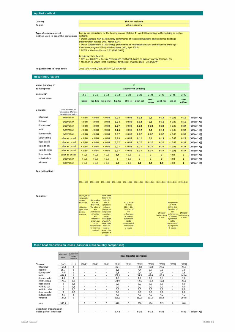
Applied method
CountryRegion
Requirements in force since
Resulting U-values
Model building N° 2Building type apartment building
Variant N° 2-0 2-11 2-12 2-13 2-21 2-22 2-31 2-32 2-41 2-42variant name
basis hg-bnc hg-pellet hg-hp dhw-el dhw-solvent-
nomecvent-rec sys-el
sys-sol/rec
U-values
tilted roof < 0,08 < 0,08 < 0,08 0,24 < 0,08 0,12 0,1 0,19 < 0,08 0,19 [W/(m²K)]flat roof < 0,08 < 0,08 < 0,08 0,24 < 0,08 0,12 0,1 0,19 < 0,08 0,19 [W/(m²K)]dormer roof < 0,08 < 0,08 < 0,08 0,37 < 0,08 0,32 0,32 0,32 < 0,08 0,37 [W/(m²K)]walls < 0,08 < 0,08 < 0,08 0,24 < 0,08 0,12 0,1 0,19 < 0,08 0,32 [W/(m²K)]dormer walls < 0,08 < 0,08 < 0,08 0,37 < 0,08 0,32 0,32 0,32 < 0,08 0,37 [W/(m²K)]cellar ceiling < 0,08 < 0,08 < 0,08 0,23 < 0,08 0,12 0,1 0,19 < 0,08 0,23 [W/(m²K)]floor to soil < 0,08 < 0,08 < 0,08 0,37 < 0,08 0,37 0,37 0,37 < 0,08 0,37 [W/(m²K)]walls to soil < 0,08 < 0,08 < 0,08 0,37 < 0,08 0,37 0,37 0,37 < 0,08 0,37 [W/(m²K)]walls to cellar < 0,08 < 0,08 < 0,08 0,37 < 0,08 0,37 0,37 0,37 < 0,08 0,37 [W/(m²K)]door to cellar < 0,8 < 0,8 < 0,8 3,4 < 0,8 2 2 2 < 0,8 2 [W/(m²K)]outside door < 0,8 < 0,8 < 0,8 2 < 0,8 2 2 2 < 0,8 2 [W/(m²K)]windows < 0,8 < 0,8 < 0,8 1,8 < 0,8 1,2 0,8 1,3 < 0,8 2 [W/(m²K)]
Restricting limit
EPC<=0,80 EPC<=0,80 EPC<=0,80 EPC<=0,80 EPC<=0,80 EPC<=0,80 EPC<=0,80 EPC<=0,80 EPC<=0,80 EPC<=0,80
Remarks EPC=0,84, so not possible to meet EPC<=0,80
all heating pipes within thermal envelope
Not possible to meet
EPC<=0,8. The effect of
low performance of heating
and ventilation system can
not be compensated by improved
U-values.
Wood pellet boiler is no option in Dutch
calculation software
(except for complicated procedure
using 'declaration of quality'). Wood pellet boiler not used as
primary heat generator in
new
Not possible to meet
EPC<=0,8. The effect of
low performance of heating system can
not be compensated by improved
U-values.
Efficiency heat recovery
= 75%
Not possible to meet
EPC<=0,8. The effect of
low performance of heating system can
not be compensated by improved
U-values.
Efficiency heat recovery
= 75%
Mean heat transmission losses (basis for cross country comparison)
element area
correction factor (only for cross-
country comparison)
heat transfer coefficient
Element [m²] [ - ] [W/K] [W/K] [W/K] [W/K] [W/K] [W/K] [W/K] [W/K] [W/K] [W/K]tilted roof 150,4 1 - - - 36,1 - 18,0 15,0 28,6 - 28,6flat roof 36,7 1 - - - 8,8 - 4,4 3,7 7,0 - 7,0dormer roof 7,5 1 - - - 2,8 - 2,4 2,4 2,4 - 2,8walls 454,4 1 - - - 109,1 - 54,5 45,4 86,3 - 145,4dormer walls 4,4 1 - - - 1,6 - 1,4 1,4 1,4 - 1,6cellar ceiling 173,5 0,6 - - - 23,9 - 12,5 10,4 19,8 - 23,9floor to soil 0 0,6 - - - 0,0 - 0,0 0,0 0,0 - 0,0walls to soil 0 0,6 - - - 0,0 - 0,0 0,0 0,0 - 0,0walls to cellar 0 0,6 - - - 0,0 - 0,0 0,0 0,0 - 0,0door to cellar 0 0,6 - - - 0,0 - 0,0 0,0 0,0 - 0,0outside door 2,1 1 - - - 4,2 - 4,2 4,2 4,2 - 4,2windows 127,4 1 - - - 229,3 - 152,9 101,9 165,6 - 254,8
sum 956,4 0 0 0 416 0 250 184 315 0 468
Mean heat transmissionlosses per m² envelope - - - 0,43 - 0,26 0,19 0,33 - 0,49 [W/(m²K)]
external air
external air
external air
external air
external air
external air
cellar air or soil
cellar air or soil
cellar air or soil
cellar air or soil
cellar air or soil
external air
Energy use calculations for the heating season (October 1 - April 30) according to (for building as well as system):* Dutch Standard NEN 5128: Energy performance of residential functions and residential buildings - Determination method (NNI, March 2004).* Dutch Guideline NPR 5129: Energy performance of residential functions and residential buildings - Calculation program (EPW) with handbook (NNI, April 2005). * EPW for Windows Version 2.02 (NNI, 2006)
Requirements to be met:* EPC <= 0,8 (EPC = Energy Performance Coefficient, based on primary energy demand), and* Minimum Rc values (heat resistance) for thermal envelope (Rc >=2,5 m2K/W)
The Netherlandswhole country
U-value defined for temperature difference between room and ...
Type of requirements / method used to proof the compliance
2006 (EPC <=0,8), 1992 (Rc >= 2,5 W/(m²K))
[building 2 - results.xls]nl 03.12.2008 16:41
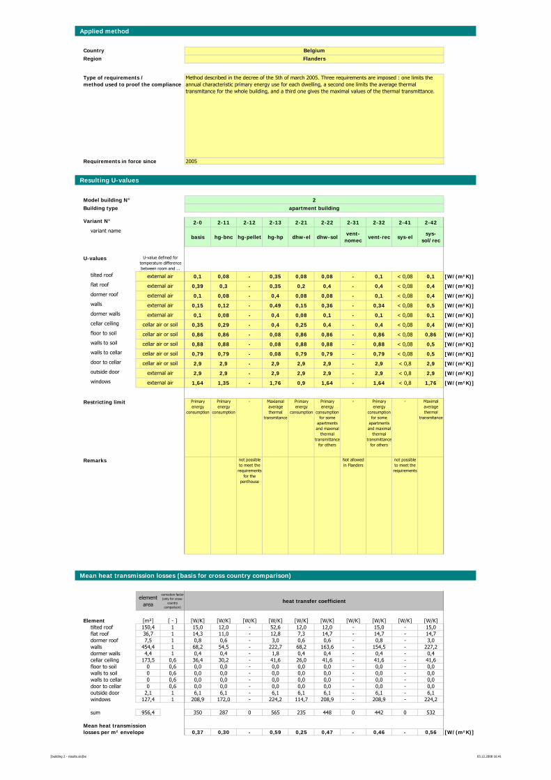
Applied method
CountryRegion
Requirements in force since
Resulting U-values
Model building N° 2Building type apartment building
Variant N° 2-0 2-11 2-12 2-13 2-21 2-22 2-31 2-32 2-41 2-42variant name
basis hg-bnc hg-pellet hg-hp dhw-el dhw-solvent-
nomecvent-rec sys-el
sys-sol/rec
U-values
tilted roof 0,1 0,08 - 0,35 0,08 0,08 - 0,1 < 0,08 0,1 [W/(m²K)]flat roof 0,39 0,3 - 0,35 0,2 0,4 - 0,4 < 0,08 0,4 [W/(m²K)]dormer roof 0,1 0,08 - 0,4 0,08 0,08 - 0,1 < 0,08 0,4 [W/(m²K)]walls 0,15 0,12 - 0,49 0,15 0,36 - 0,34 < 0,08 0,5 [W/(m²K)]dormer walls 0,1 0,08 - 0,4 0,08 0,1 - 0,1 < 0,08 0,1 [W/(m²K)]cellar ceiling 0,35 0,29 - 0,4 0,25 0,4 - 0,4 < 0,08 0,4 [W/(m²K)]floor to soil 0,86 0,86 - 0,08 0,86 0,86 - 0,86 < 0,08 0,86 [W/(m²K)]walls to soil 0,88 0,88 - 0,08 0,88 0,88 - 0,88 < 0,08 0,5 [W/(m²K)]walls to cellar 0,79 0,79 - 0,08 0,79 0,79 - 0,79 < 0,08 0,5 [W/(m²K)]door to cellar 2,9 2,9 - 2,9 2,9 2,9 - 2,9 < 0,8 2,9 [W/(m²K)]outside door 2,9 2,9 - 2,9 2,9 2,9 - 2,9 < 0,8 2,9 [W/(m²K)]windows 1,64 1,35 - 1,76 0,9 1,64 - 1,64 < 0,8 1,76 [W/(m²K)]
Restricting limit Primary energy
consumption
Primary energy
consumption
- Maxiamal average thermal
transmitance
Primary energy
consumption
Primary energy
consumption for some
apartments and maximal
thermal transmittance
for others
- Primary energy
consumption for some
apartments and maximal
thermal transmittance
for others
- Maximal average thermal
transmitance
Remarks not possible to meet the
requirements for the
penthouse
Not allowed in Flanders
not possible to meet the
requirements
Mean heat transmission losses (basis for cross country comparison)
element area
correction factor (only for cross-
country comparison)
heat transfer coefficient
Element [m²] [ - ] [W/K] [W/K] [W/K] [W/K] [W/K] [W/K] [W/K] [W/K] [W/K] [W/K]tilted roof 150,4 1 15,0 12,0 - 52,6 12,0 12,0 - 15,0 - 15,0flat roof 36,7 1 14,3 11,0 - 12,8 7,3 14,7 - 14,7 - 14,7dormer roof 7,5 1 0,8 0,6 - 3,0 0,6 0,6 - 0,8 - 3,0walls 454,4 1 68,2 54,5 - 222,7 68,2 163,6 - 154,5 - 227,2dormer walls 4,4 1 0,4 0,4 - 1,8 0,4 0,4 - 0,4 - 0,4cellar ceiling 173,5 0,6 36,4 30,2 - 41,6 26,0 41,6 - 41,6 - 41,6floor to soil 0 0,6 0,0 0,0 - 0,0 0,0 0,0 - 0,0 - 0,0walls to soil 0 0,6 0,0 0,0 - 0,0 0,0 0,0 - 0,0 - 0,0walls to cellar 0 0,6 0,0 0,0 - 0,0 0,0 0,0 - 0,0 - 0,0door to cellar 0 0,6 0,0 0,0 - 0,0 0,0 0,0 - 0,0 - 0,0outside door 2,1 1 6,1 6,1 - 6,1 6,1 6,1 - 6,1 - 6,1windows 127,4 1 208,9 172,0 - 224,2 114,7 208,9 - 208,9 - 224,2
sum 956,4 350 287 0 565 235 448 0 442 0 532
Mean heat transmissionlosses per m² envelope 0,37 0,30 - 0,59 0,25 0,47 - 0,46 - 0,56 [W/(m²K)]
cellar air or soil
external air
Method described in the decree of the 5th of march 2005. Three requirements are imposed : one limits the annual characteristic primary energy use for each dwelling, a second one limits the average thermal transmitance for the whole building, and a third one gives the maximal values of the thermal transmittance.
BelgiumFlanders
U-value defined for temperature difference between room and ...
Type of requirements / method used to proof the compliance
2005
external air
external air
external air
external air
external air
external air
cellar air or soil
cellar air or soil
cellar air or soil
cellar air or soil
[building 2 - results.xls]be 03.12.2008 16:41
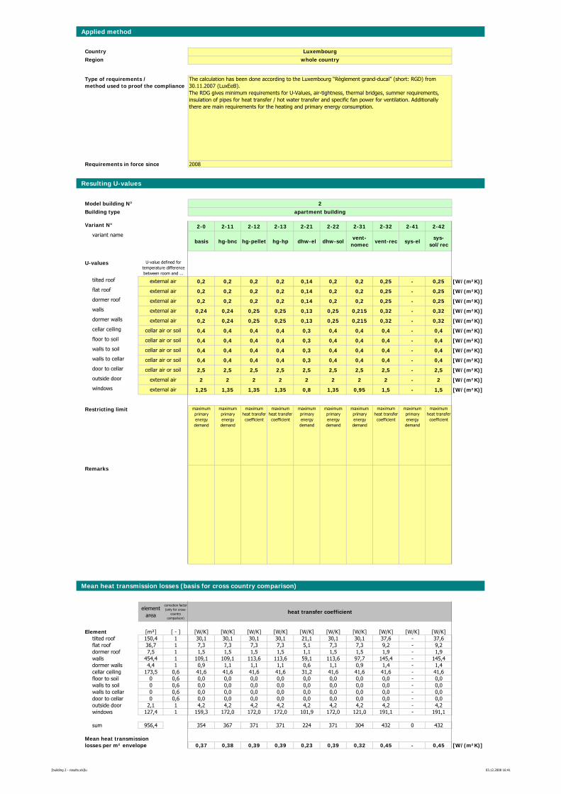
Applied method
CountryRegion
Requirements in force since
Resulting U-values
Model building N° 2Building type apartment building
Variant N° 2-0 2-11 2-12 2-13 2-21 2-22 2-31 2-32 2-41 2-42variant name
basis hg-bnc hg-pellet hg-hp dhw-el dhw-solvent-
nomecvent-rec sys-el
sys-sol/rec
U-values
tilted roof 0,2 0,2 0,2 0,2 0,14 0,2 0,2 0,25 - 0,25 [W/(m²K)]flat roof 0,2 0,2 0,2 0,2 0,14 0,2 0,2 0,25 - 0,25 [W/(m²K)]dormer roof 0,2 0,2 0,2 0,2 0,14 0,2 0,2 0,25 - 0,25 [W/(m²K)]walls 0,24 0,24 0,25 0,25 0,13 0,25 0,215 0,32 - 0,32 [W/(m²K)]dormer walls 0,2 0,24 0,25 0,25 0,13 0,25 0,215 0,32 - 0,32 [W/(m²K)]cellar ceiling 0,4 0,4 0,4 0,4 0,3 0,4 0,4 0,4 - 0,4 [W/(m²K)]floor to soil 0,4 0,4 0,4 0,4 0,3 0,4 0,4 0,4 - 0,4 [W/(m²K)]walls to soil 0,4 0,4 0,4 0,4 0,3 0,4 0,4 0,4 - 0,4 [W/(m²K)]walls to cellar 0,4 0,4 0,4 0,4 0,3 0,4 0,4 0,4 - 0,4 [W/(m²K)]door to cellar 2,5 2,5 2,5 2,5 2,5 2,5 2,5 2,5 - 2,5 [W/(m²K)]outside door 2 2 2 2 2 2 2 2 - 2 [W/(m²K)]windows 1,25 1,35 1,35 1,35 0,8 1,35 0,95 1,5 - 1,5 [W/(m²K)]
Restricting limit maximum primary energy demand
maximum primary energy demand
maximum heat transfer coefficient
maximum heat transfer coefficient
maximum primary energy demand
maximum primary energy demand
maximum primary energy demand
maximum heat transfer coefficient
maximum primary energy demand
maximum heat transfer coefficient
Remarks
Mean heat transmission losses (basis for cross country comparison)
element area
correction factor (only for cross-
country comparison)
heat transfer coefficient
Element [m²] [ - ] [W/K] [W/K] [W/K] [W/K] [W/K] [W/K] [W/K] [W/K] [W/K] [W/K]tilted roof 150,4 1 30,1 30,1 30,1 30,1 21,1 30,1 30,1 37,6 - 37,6flat roof 36,7 1 7,3 7,3 7,3 7,3 5,1 7,3 7,3 9,2 - 9,2dormer roof 7,5 1 1,5 1,5 1,5 1,5 1,1 1,5 1,5 1,9 - 1,9walls 454,4 1 109,1 109,1 113,6 113,6 59,1 113,6 97,7 145,4 - 145,4dormer walls 4,4 1 0,9 1,1 1,1 1,1 0,6 1,1 0,9 1,4 - 1,4cellar ceiling 173,5 0,6 41,6 41,6 41,6 41,6 31,2 41,6 41,6 41,6 - 41,6floor to soil 0 0,6 0,0 0,0 0,0 0,0 0,0 0,0 0,0 0,0 - 0,0walls to soil 0 0,6 0,0 0,0 0,0 0,0 0,0 0,0 0,0 0,0 - 0,0walls to cellar 0 0,6 0,0 0,0 0,0 0,0 0,0 0,0 0,0 0,0 - 0,0door to cellar 0 0,6 0,0 0,0 0,0 0,0 0,0 0,0 0,0 0,0 - 0,0outside door 2,1 1 4,2 4,2 4,2 4,2 4,2 4,2 4,2 4,2 - 4,2windows 127,4 1 159,3 172,0 172,0 172,0 101,9 172,0 121,0 191,1 - 191,1
sum 956,4 354 367 371 371 224 371 304 432 0 432
Mean heat transmissionlosses per m² envelope 0,37 0,38 0,39 0,39 0,23 0,39 0,32 0,45 - 0,45 [W/(m²K)]
cellar air or soil
external air
The calculation has been done according to the Luxembourg “Règlement grand-ducal” (short: RGD) from 30.11.2007 (LuxEeB).The RDG gives minimum requirements for U-Values, air-tightness, thermal bridges, summer requirements, insulation of pipes for heat transfer / hot water transfer and specific fan power for ventilation. Additionally there are main requirements for the heating and primary energy consumption.
Luxembourgwhole country
U-value defined for temperature difference between room and ...
Type of requirements / method used to proof the compliance
2008
external air
external air
external air
external air
external air
external air
cellar air or soil
cellar air or soil
cellar air or soil
cellar air or soil
[building 2 - results.xls]lu 03.12.2008 16:41
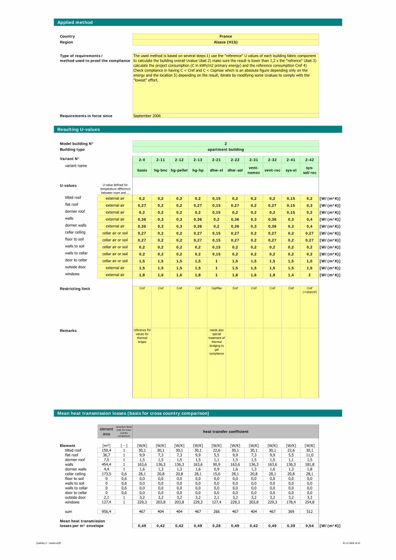
Applied method
CountryRegion
Requirements in force since
Resulting U-values
Model building N° 2Building type apartment building
Variant N° 2-0 2-11 2-12 2-13 2-21 2-22 2-31 2-32 2-41 2-42variant name
basis hg-bnc hg-pellet hg-hp dhw-el dhw-solvent-
nomecvent-rec sys-el
sys-sol/rec
U-values
tilted roof 0,2 0,2 0,2 0,2 0,15 0,2 0,2 0,2 0,15 0,2 [W/(m²K)]flat roof 0,27 0,2 0,2 0,27 0,15 0,27 0,2 0,27 0,15 0,3 [W/(m²K)]dormer roof 0,2 0,2 0,2 0,2 0,15 0,2 0,2 0,2 0,15 0,2 [W/(m²K)]walls 0,36 0,3 0,3 0,36 0,2 0,36 0,3 0,36 0,3 0,4 [W/(m²K)]dormer walls 0,36 0,3 0,3 0,36 0,2 0,36 0,3 0,36 0,3 0,4 [W/(m²K)]cellar ceiling 0,27 0,2 0,2 0,27 0,15 0,27 0,2 0,27 0,2 0,27 [W/(m²K)]floor to soil 0,27 0,2 0,2 0,27 0,15 0,27 0,2 0,27 0,2 0,27 [W/(m²K)]walls to soil 0,2 0,2 0,2 0,2 0,15 0,2 0,2 0,2 0,2 0,2 [W/(m²K)]walls to cellar 0,2 0,2 0,2 0,2 0,15 0,2 0,2 0,2 0,2 0,2 [W/(m²K)]door to cellar 1,5 1,5 1,5 1,5 1 1,5 1,5 1,5 1,5 1,5 [W/(m²K)]outside door 1,5 1,5 1,5 1,5 1 1,5 1,5 1,5 1,5 1,5 [W/(m²K)]windows 1,8 1,6 1,6 1,8 1 1,8 1,6 1,8 1,4 2 [W/(m²K)]
Restricting limit Cref Cref Cref Cref CepMax Cref Cref Cref Cref Cref (+Ubatref)
Remarks reference Psi values for thermal briges
needs also special
treatment of thermal
bridging to get
compliance
Mean heat transmission losses (basis for cross country comparison)
element area
correction factor (only for cross-
country comparison)
heat transfer coefficient
Element [m²] [ - ] [W/K] [W/K] [W/K] [W/K] [W/K] [W/K] [W/K] [W/K] [W/K] [W/K]tilted roof 150,4 1 30,1 30,1 30,1 30,1 22,6 30,1 30,1 30,1 22,6 30,1flat roof 36,7 1 9,9 7,3 7,3 9,9 5,5 9,9 7,3 9,9 5,5 11,0dormer roof 7,5 1 1,5 1,5 1,5 1,5 1,1 1,5 1,5 1,5 1,1 1,5walls 454,4 1 163,6 136,3 136,3 163,6 90,9 163,6 136,3 163,6 136,3 181,8dormer walls 4,4 1 1,6 1,3 1,3 1,6 0,9 1,6 1,3 1,6 1,3 1,8cellar ceiling 173,5 0,6 28,1 20,8 20,8 28,1 15,6 28,1 20,8 28,1 20,8 28,1floor to soil 0 0,6 0,0 0,0 0,0 0,0 0,0 0,0 0,0 0,0 0,0 0,0walls to soil 0 0,6 0,0 0,0 0,0 0,0 0,0 0,0 0,0 0,0 0,0 0,0walls to cellar 0 0,6 0,0 0,0 0,0 0,0 0,0 0,0 0,0 0,0 0,0 0,0door to cellar 0 0,6 0,0 0,0 0,0 0,0 0,0 0,0 0,0 0,0 0,0 0,0outside door 2,1 1 3,2 3,2 3,2 3,2 2,1 3,2 3,2 3,2 3,2 3,2windows 127,4 1 229,3 203,8 203,8 229,3 127,4 229,3 203,8 229,3 178,4 254,8
sum 956,4 467 404 404 467 266 467 404 467 369 512
Mean heat transmissionlosses per m² envelope 0,49 0,42 0,42 0,49 0,28 0,49 0,42 0,49 0,39 0,54 [W/(m²K)]
cellar air or soil
external air
The used method is based on several steps:1) use the "reference" U values of each building fabric component to calculate the building overall Uvalue Ubat 2) make sure the result is lower than 1,2 x the "refrence" Ubat 3) calculate the project consumption (C in kWh/m2 primary energy) and the reference consumption Cref 4) Check compliance in having C < Cref and C < Cepmax which is an absolute figure depending only on the energy and the location 5) depending on the result, iterate by modifying some Uvalues to comply with the "lowest" effort.
FranceAlsace (H1b)
U-value defined for temperature difference between room and ...
Type of requirements / method used to proof the compliance
September 2006
external air
external air
external air
external air
external air
external air
cellar air or soil
cellar air or soil
cellar air or soil
cellar air or soil
[building 2 - results.xls]fr 03.12.2008 16:41
Energy Performance Requirements for New Buildings – Exemplary Comparison
Appendix 3: Definition of Model Building 3 – school
Appendix 3a: Plans
A-56
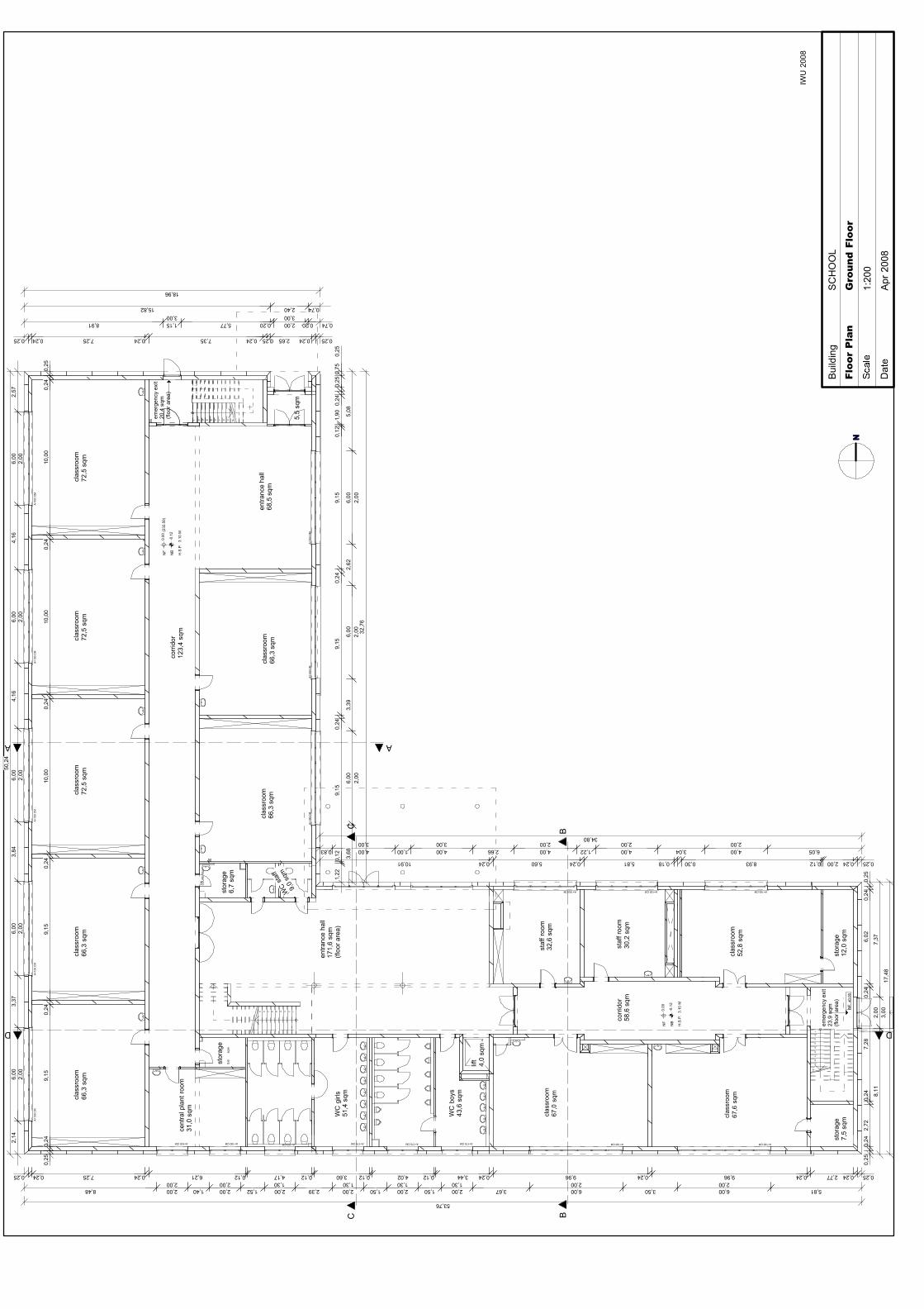
4 123
emer
genc
y ex
it20
,4 s
qm(fl
oor a
rea)
entra
nce
hall
68,5
sqm
clas
sroo
m66
,3 s
qm
clas
sroo
m72
,5 s
qmcl
assr
oom
72,5
sqm
clas
sroo
m72
,5 s
qmcl
assr
oom
66,3
sqm
AB
A=100 CMA=100 CMA=100 CM
A=1
00 C
MA
=100
CM
A=1
00 C
M
A=100 CM
A=1
00 C
MA
=100
CM
A=1
00 C
MA
=100
CM
A=1
00 C
M
A=100 CMA=100 CMA=170 CMA=170 CMA=170 CMA=170 CM
WC
girl
s51
,4 s
qm
staf
f roo
m32
,6 s
qm
clas
sroo
m66
,3 s
qm
corr
idor
123,
4 sq
m
entra
nce
hall
171,
6 sq
m(fl
oor a
rea)
staf
f roo
m30
,2 s
qm
cent
ral p
lant
room
31,0
sqm
clas
sroo
m52
,8 s
qm
stor
age
6,7
sqm
A=100 CM
WC
boy
s43
,6 s
qm
clas
sroo
m67
,6 s
qm
T30
CO
UP
E FE
U
clas
sroo
m67
,0 s
qm
H.S
.P.
3.1
0 M
clas
sroo
m66
,3 s
qm
stor
age
12,0
sqm
stor
age
7,5
sqm
corr
idor
58,6
sqm
stor
age
5,6
sqm
emer
genc
y ex
it23
,9 s
qm(fl
oor a
rea)
BCC
A
D D
lift
4,0
sqm
5,5
sqm
10541 2 3 6 7 8 9541 2 3
0.00
-0.1
2
NF
NB
(232
.50)
10
5
4
1
2
3
6
7
8
9
NF:
±0.
00
9 678 5
WC
staf
f
9,0
sqm
0.00
-0.1
2
NF
NB
H.S
.P.
3.1
0 M
NFl
oor
Pla
nG
roun
d F
loor
1:20
0
Dat
eA
pr 2
008
Bui
ldin
gS
CH
OO
L
IWU
200
8
0,25
0,24
9,15
0,24
9,15
0,24
10,0
00,
2410
,00
0,24
10,0
00,
240,
25
2,14
6,00
3,37
6,00
3,84
6,00
4,16
6,00
4,16
6,00
2,57
50,2
4
0,25 0,24 7,25 0,24 6,21 0,12 4,17 0,12 3,60 0,12 4,02 0,12 3,44 0,24 9,96 0,24 9,96 0,24 2,77 0,24 0,25
8,48 2,00 1,40 2,00 1,52 2,00 2,39 2,00 1,50 2,00 1,50 2,00 3,67 6,00 3,50 6,00 5,81
53,76
0,25
0,24
2,72
0,24
7,28
0,24
6,02
0,24
0,25
8,11
2,00
7,37
17,4
8
10,91 0,24 5,60 0,24 5,81 0,18 0,30 8,93 0,12 2,00 0,24 0,25
0,83 4,00 1,00 4,00 2,66 4,00 1,22 4,00 3,04 4,00 6,05
34,80
1,22
0,12
9,15
0,24
9,15
0,24
9,15
0,12
1,90
0,24
0,25
0,75
0,25
3,68
6,00
3,39
6,00
2,62
6,00
5,08
32,7
6
0,25 0,24 7,25 0,24 7,35 0,24 0,25 2,65 0,24 0,25
8,91 1,15 5,77 0,20 2,00 0,20 0,74
15,82 2,40 0,74
18,96
2,00
2,00
2,00
2,00
2,00
3,00
2,00
2,00
2,00
3,00 3,00 2,00 2,00 2,00
3,00
1,30 1,30 1,30 2,00 2,001,302,002,00
3,00
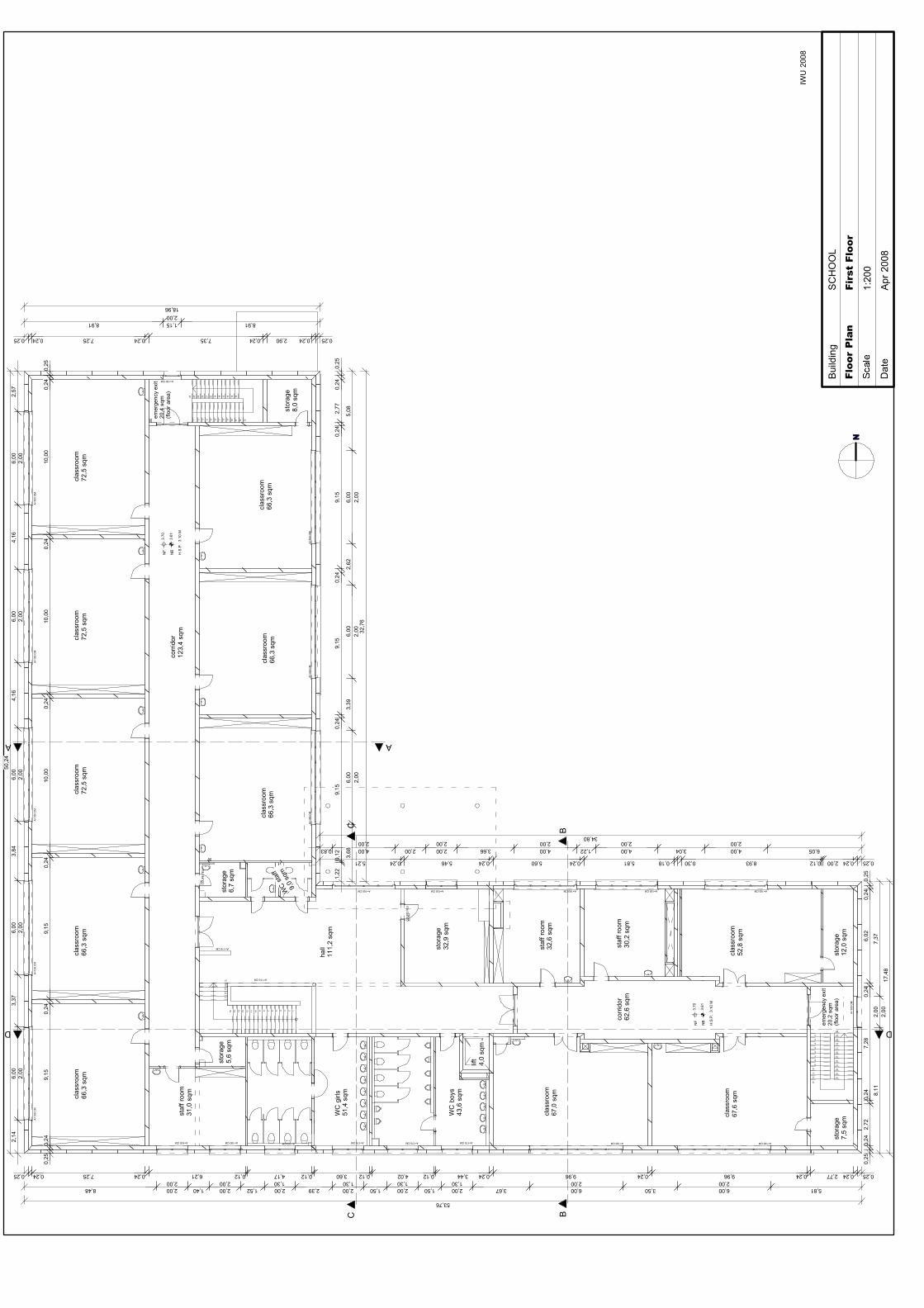
9 678 5 4 123
clas
sroo
m66
,3 s
qmcl
assr
oom
66,3
sqm
clas
sroo
m72
,5 s
qmcl
assr
oom
72,5
sqm
clas
sroo
m72
,5 s
qmcl
assr
oom
66,3
sqm
stor
age
32,9
sqm
AB
3.70
3.61
3.70
3.61
A=100 CMA=100 CMA=100 CM
A=1
00 C
MA
=100
CM
A=1
00 C
M
A=100 CM
A=1
00 C
MA
=100
CM
A=1
00 C
MA
=100
CM
A=1
00 C
M
A=100 CMA=100 CMA=170 CMA=170 CMA=170 CMA=170 CM
WC
girl
s51
,4 s
qm
staf
f roo
m32
,6 s
qm
clas
sroo
m66
,3 s
qm
corr
idor
123,
4 sq
m
hall
111,
2 sq
m
staf
f roo
m30
,2 s
qm
A=100 CM
NF
NB
NF
NB
13
15
16
17
18
19
14
20
21
22
23
24
25
12
10
11
5
4
2
3
6
7
8
91210 11 13541 2 3 6 7 8 9
1516171819 14202122232425
21
19
20
17
18
emer
genc
y ex
it20
,4 s
qm(fl
oor a
rea)
staf
f roo
m31
,0 s
qm
clas
sroo
m52
,8 s
qm
A=1
00 C
M
CO
UP
E FE
U30
min
A=100 CM
WC
boy
s43
,6 s
qm
clas
sroo
m67
,6 s
qm
A=115 CM
A=115 CM
T30
CO
UP
E FE
U
clas
sroo
m67
,0 s
qm
H.S
.P.
3.1
0 M
H.S
.P.
3.1
0 M
clas
sroo
m66
,3 s
qm
A=100 CM
stor
age
8,0
sqm
corr
idor
62,6
sqm
stor
age
5,6
sqm
emer
genc
y ex
it20
,2 s
qm(fl
oor a
rea)
BCC
A
A=100 CM
1415 1316 12 1011
D D
stor
age
6,7
sqm
WC
staf
f
9,0
sqm
lift
4,0
sqm
stor
age
12,0
sqm
stor
age
7,5
sqm
NFl
oor
Pla
nFi
rst
Floo
r
1:20
0
Dat
eA
pr 2
008
Bui
ldin
gS
CH
OO
L
IWU
200
8
0,25
0,24
9,15
0,24
9,15
0,24
10,0
00,
2410
,00
0,24
10,0
00,
240,
25
2,14
6,00
3,37
6,00
3,84
6,00
4,16
6,00
4,16
6,00
2,57
50,2
4
0,25 0,24 7,25 0,24 6,21 0,12 4,17 0,12 3,60 0,12 4,02 0,12 3,44 0,24 9,96 0,24 9,96 0,24 2,77 0,24 0,25
8,48 2,00 1,40 2,00 1,52 2,00 2,39 2,00 1,50 2,00 1,50 2,00 3,67 6,00 3,50 6,00 5,81
53,76
0,25
0,24
2,72
0,24
7,28
0,24
6,02
0,24
0,25
8,11
2,00
7,37
17,4
8
5,46 0,24 5,60 0,24 5,81 0,18 0,30 8,93 0,12 2,00 0,24 0,25
0,83 4,00 2,00 2,00 3,66 4,00 1,22 4,00 3,04 4,00 6,05
34,80
1,22
0,12
9,15
0,24
9,15
0,24
9,15
0,24
2,77
0,24
0,25
3,68
6,00
3,39
6,00
2,62
6,00
5,08
32,7
6
0,25 0,24 7,25 0,24 7,35 0,24 2,90 0,24 0,25
18,96
5,21 0,24
8,91 1,15 8,91
2,00
2,00
2,00
2,00
2,00
2,00
2,00
2,00
2,00
2,00 2,00 2,00 2,00 2,00
2,00
1,30 1,30 1,30 2,00 2,001,302,002,00
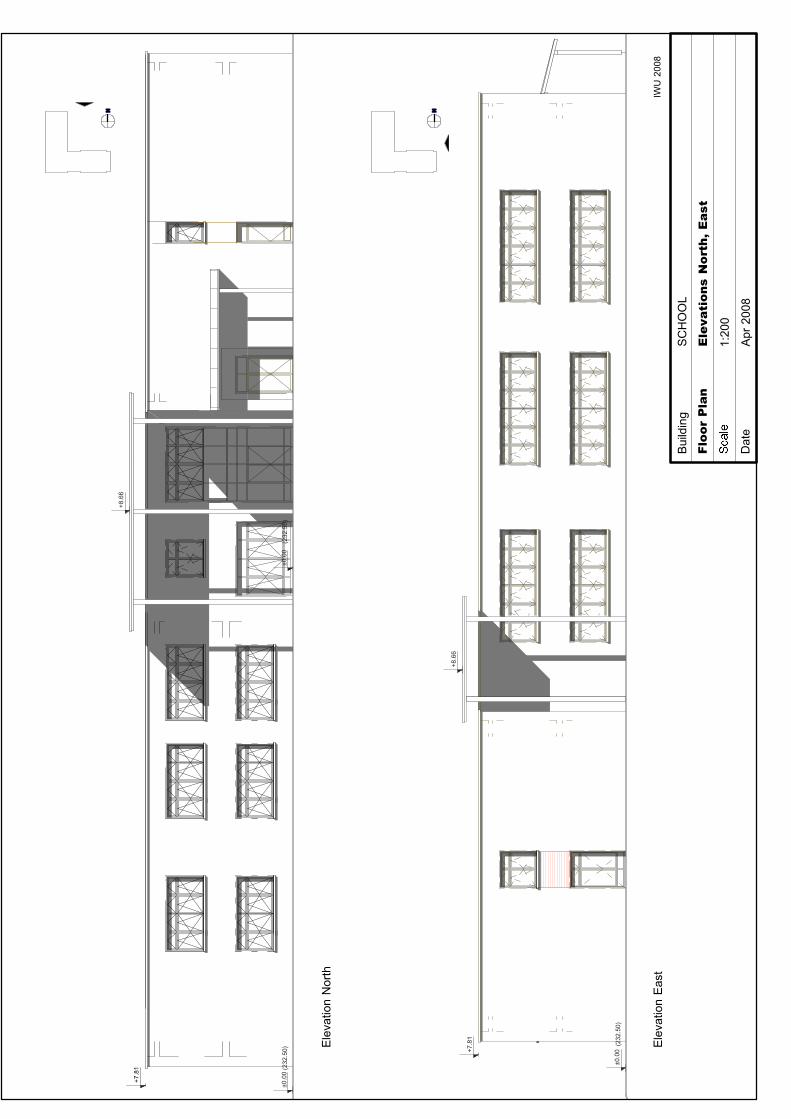
±0.0
0+7.8
1
+8.6
6
(232
.50)
+8.6
6
±0.0
0(2
32.5
0)
+7.8
1
±0.0
0(2
32.5
0)
Floo
r P
lan
Ele
vati
ons
Nor
th,
Eas
t
1:20
0
Dat
eA
pr 2
008
Bui
ldin
gS
CH
OO
L
IWU
200
8
Ele
vatio
n N
orth
Ele
vatio
n E
ast
N N
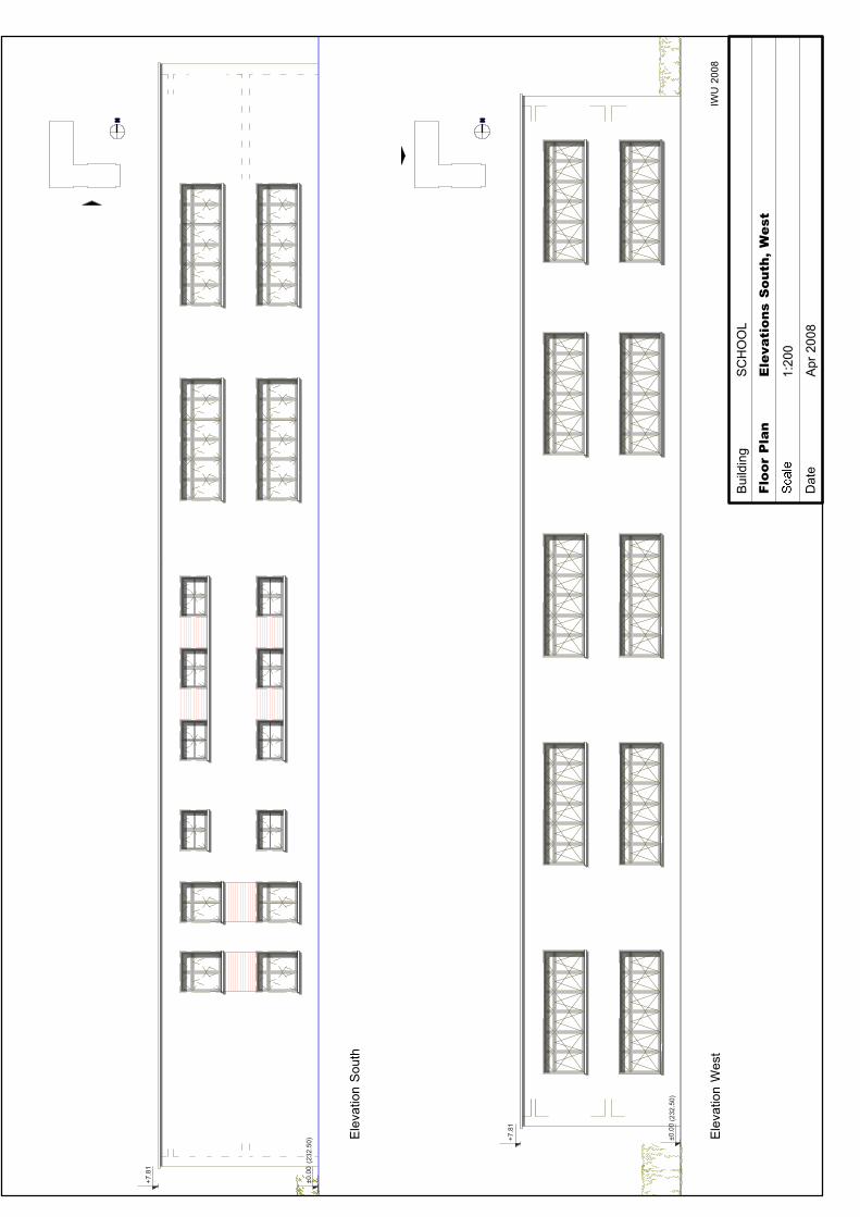
±0.0
0
+7.8
1
(232
.50) ±0
.00
+7.8
1
(232
.50)
Floo
r P
lan
Ele
vati
ons
Sou
th,
Wes
t
1:20
0
Dat
eA
pr 2
008
Bui
ldin
gS
CH
OO
L
IWU
200
8
N N
Ele
vatio
n S
outh
Ele
vatio
n W
est
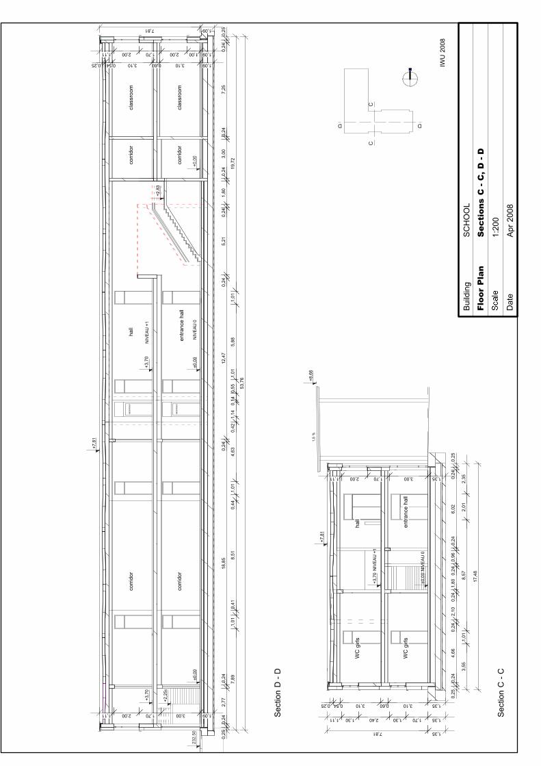
CC
D D
+7,8
1
+8,6
6
+3,7
0N
IVE
AU
+1
hall
1,5
%
WC
girl
s
entra
nce
hall
+2,2
55
+0,0
0±0
,00
±0,0
023
2.50
corr
idor
corr
idor
clas
sroo
m
NIV
EA
U 0
asce
nceu
r
+7,8
1
+2,8
3
+3,7
0+3
,70
corr
idor
hall
corr
idor
clas
sroo
m
NIV
EA
U +
1
asce
nceu
r
entra
nce
hall
WC
girl
s
±0,0
0N
IVE
AU
0
N
Floo
r P
lan
Sec
tion
s C
- C
, D -
D
1:20
0
Dat
eA
pr 2
008
Bui
ldin
gS
CH
OO
L
IWU
200
8
Sec
tion
D -
D
Sec
tion
C -
C
0,25
0,24
2,77
0,24
18,8
50,
2412
,47
0,24
5,21
0,24
1,80
0,24
3,00
7,89
1,01
0,41
8,51
0,44
1,01
4,63
0,42
1,14
0,14
0,55
1,01
5,88
1,01
19,7
2
0,24
7,25
0,24
0,25
53,7
6
0,54 3,10 0,60 3,10 1,090,25
1,11 2,00 1,70 2,00 1,00 1,09
7,81 1,09
4,66
0,24
2,10
0,24
1,80
0,24
0,96
0,24
6,02
0,24
0,25
3,55
1,01
8,57
2,01
2,35
0,25
0,24
17,4
8
0,25 0,54 3,10 0,60 3,10 1,35
1,11 1,30 2,40 1,30 1,70 1,35
7,81 1,35
1,11 2,00 1,70 3,00 1,35
1,11 2,00 1,70 3,00 1,09
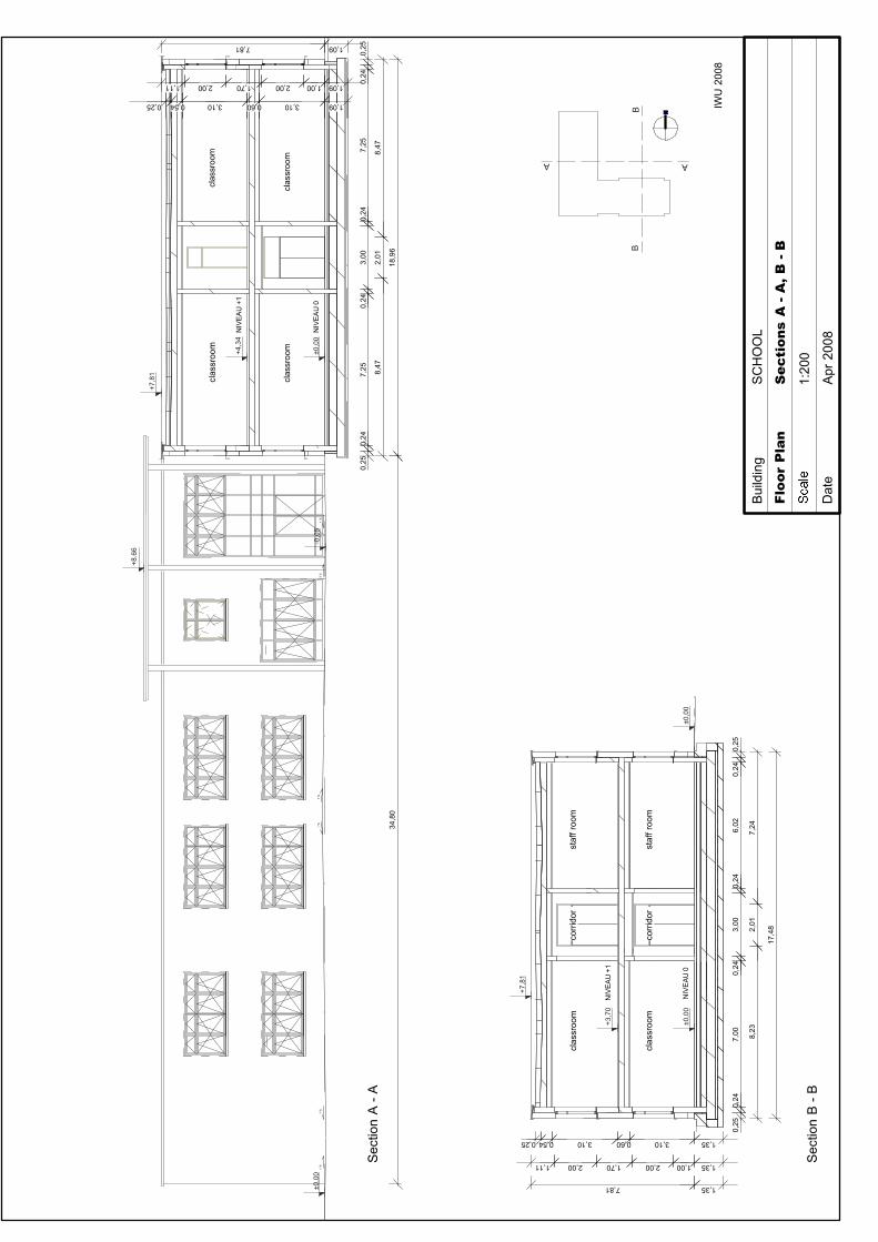
±0,0
0
+8.6
6
clas
sroo
m
1 %
1 %
1 %
1 %
1 %
1 %
clas
sroo
m
+7,8
1
+4,3
4
clas
sroo
mcl
assr
oom
NIV
EA
U +
1
±0,0
0N
IVE
AU
0
0,25
0,24
7,25
0,24
3,00
0,24
7,25
0,24
0,25
8,47
2,01
8,47
18,9
634
,80
-0,0
5
±0,0
0
+7,8
1
±0,0
0
+3,7
0N
IVE
AU
+1
NIV
EA
U 0
clas
sroo
mco
rrid
orst
aff r
oom
clas
sroo
mco
rrid
orst
aff r
oom
0,25
0,24
7,00
0,24
3,00
0,24
6,02
0,24
0,25
8,23
2,01
7,24
17,4
8
0,25 0,54 3,10 0,60 3,10 1,35
1,11 2,00 1,70 2,00 1,00 1,35
7,81 1,35
N
Floo
r P
lan
Sec
tion
s A
- A
, B -
B
1:20
0
Dat
eA
pr 2
008
Bui
ldin
gS
CH
OO
L
IWU
200
8
AA
BB
Sec
tion
A -
A
Sec
tion
B -
B
0,25 0,54 3,10 0,60 3,10 1,09
1,11 2,00 1,70 2,00 1,00 1,09
7,81 1,09
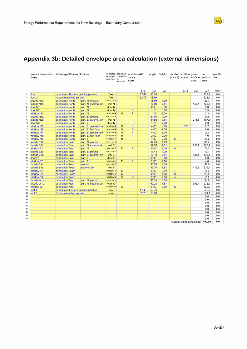
Energy Performance Requirements for New Buildings – Exemplary Comparison
Appendix 3b: Detailed envelope area calculation (external dimensions)
name area element (free)
dedicated envelope area type
dedicated orientation for windows
reduction area: insert "R"
width length height number (if <> 1)
additional area
gross surface area
net surface area
specific loss
[m] [m] [m] [m²] [m²] [m²] [W/K]1. floor 1 central and Eastern building partition floor 17,48 53,76 939,7 0,02. floor 2 Northern building partition floor 32,76 18,96 621,1 0,03. facade N1a orientation North part. N, ground wall to soil N 18,96 1,09 20,7 0,04. facade N1b orientation North part. N, external air wall N 18,96 7,81 148,1 136,3 0,05. door N1 orientation North part. N door N R 2,00 3,00 6,0 0,06. door N2 orientation North part. N door N R 1,15 3,00 3,5 0,07. window N1 orientation North part. N window N N R 1,15 2,00 2,3 0,08. facade N2a orientation North part. E, ground wall to soil N 34,80 1,09 37,9 0,09. facade N2b orientation North part. E, external air wall N 34,80 7,81 271,8 187,8 0,0
10. door N3 orientation North part. E door N R 1,15 2,00 2,3 0,011. window N2 orientation North part. E, ground floor window N N R 4,00 3,00 -2,30 9,7 0,012. window N3 orientation North part. E, first floor window N N R 4,00 2,00 8,0 0,013. window N4 orientation North part. E, ground floor window N N R 4,00 3,00 12,0 0,014. window N5 orientation North part. E, first floor window N N R 2,00 2,00 4,0 0,015. window N6 orientation North part. E window N N R 4,00 2,00 6 48,0 0,016. facade E1a orientation East part. N, ground wall to soil E 32,76 1,09 35,7 0,017. facade E1b orientation East part. N, external air wall E 32,76 7,81 255,9 183,9 0,018. window E1 orientation East part. N window E E R 6,00 2,00 6 72,0 0,019. facade E2a orientation East part. E, ground wall to soil E 17,48 1,09 19,1 0,020. facade E2b orientation East part. E, external air wall E 17,48 7,81 136,5 126,5 0,021. door E1 orientation East part. E door E R 2,00 3,00 6,0 0,022. window E2 orientation East part. E window E E R 2,00 2,00 4,0 0,023. facade S1a orientation South ground wall to soil S 53,76 1,09 58,6 0,024. facade S1b orientation South external air wall S 53,76 7,81 419,9 335,1 0,025. window S1 orientation South window S S R 6,00 2,00 4 48,0 0,026. window S2 orientation South window S S R 2,00 1,30 8 20,8 0,027. window S3 orientation South window S S R 2,00 2,00 4 16,0 0,028. facade W1a orientation West part. N, ground wall to soil W 50,24 1,09 54,8 0,029. facade W1b orientation West part. N, external air wall W 50,24 7,81 392,4 272,4 0,030. window W1 orientation West window W W R 6,00 2,00 10 120,0 0,031. roof 1 central and Eastern building partition roof 17,48 53,76 939,7 0,032. roof 2 Northern building partition roof 32,76 18,96 621,1 0,033. 0,0 0,034. 0,0 0,035. 0,0 0,036. 0,0 0,037. 0,0 0,038. 0,0 0,039. 0,0 0,040. 0,0 0,0
Gesamt thermische Hülle: 4972,9 0,0
further specification / location
A-63
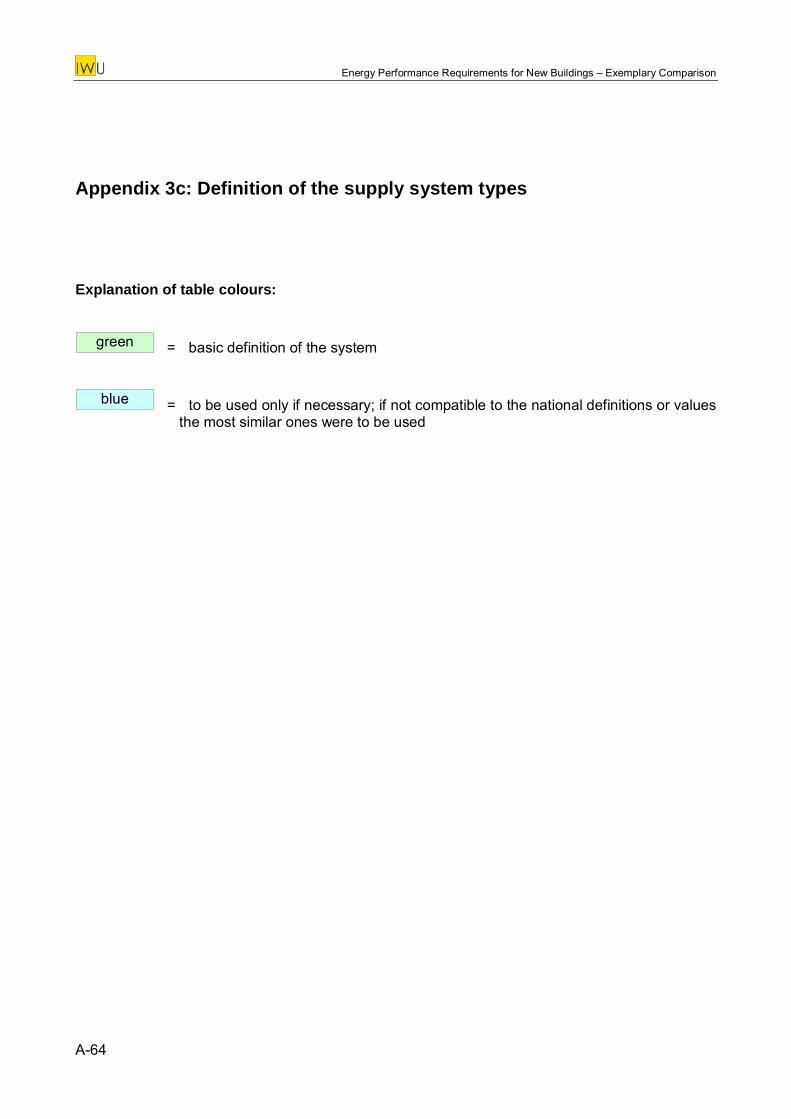
Energy Performance Requirements for New Buildings – Exemplary Comparison
Appendix 3c: Definition of the supply system types
Explanation of table colours:
= basic definition of the system green
= to be used only if necessary; if not compatible to the national definitions or values the most similar ones were to be used
blue
A-64
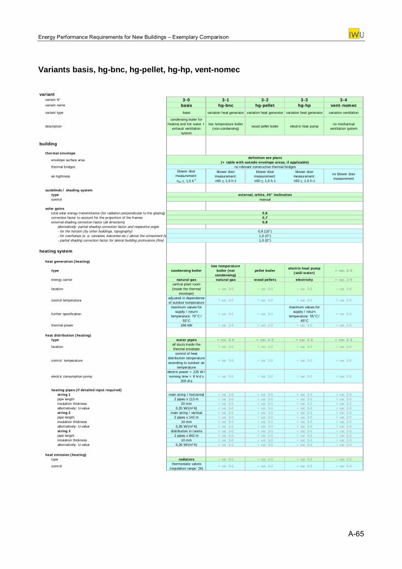
Energy Performance Requirements for New Buildings – Exemplary Comparison
Variants basis, hg-bnc, hg-pellet, hg-hp, vent-nomec variant
variant N° 3-0 3-1 3-2 3-3 3-4variant name basis hg-bnc hg-pellet hg-hp vent-nomec
variant type basis variation heat generator variation heat generator variation heat generator variation ventilation
description
condensing boiler for heating and hot water +
exhaust ventilation system
low temperature boiler (non-condensing)
wood pellet boiler electric heat pumpno mechanical
ventilation system
building
thermal envelope
envelope surface areadefinition see plans
(+ table with outside envelope areas, if applicable)thermal bridges no relevant constructive thermal bridges
air-tightnessblower door
measurement: n50 < 1,5 h-1
blower door measurement: n50 < 1,5 h-1
blower door measurement: n50 < 1,5 h-1
blower door measurement: n50 < 1,5 h-1
no blower door measurement
sunblinds / shading systemtype external, white, 45° inclinationcontrol manual
solar gainstotal solar energy transmittance (for radiation perpendicular to the glazing) 0,6correction factor to account for the proportion of the frames 0,7external shading correction factor (all directions) 0,9
alternatively: partial shading correction factor and respective angle- for the horizon (by other buildings, topography) 0,9 (10°)- for overhangs (e. g. canopies, balconies etc.) above the component be 1,0 (0°)- partial shading correction factor for lateral building protrusions (fins) 1,0 (0°)
heating system
heat generation (heating)
type condensing boilerlow temperature
boiler (not condensing)
pellet boilerelectric heat pump
(soil/water)= var. 3-0
energy carrier natural gas natural gas wood pellets electricity = var. 3-0
locationcentral plant room (inside the thermal
envelope)= var. 3-0 = var. 3-0 = var. 3-0 = var. 3-0
control temperatureadjusted in dependence of outdoor temperature
= var. 3-0 = var. 3-0 = var. 3-0 = var. 3-0
further specification
maximum values for supply / return
temperature: 70°C / 55°C
= var. 3-0 = var. 3-0
maximum values for supply / return
temperature: 55°C / 45°C
= var. 3-0
thermal power 166 kW = var. 3-0 = var. 3-0 = var. 3-0 = var. 3-0
heat distribution (heating)type water pipes = var. 3-0 = var. 3-0 = var. 3-0 = var. 3-0
locationall ducts inside the thermal envelope
= var. 3-0 = var. 3-0 = var. 3-0 = var. 3-0
control temperature
control of heat distribution temperature according to outdoor air
temperature
= var. 3-0 = var. 3-0 = var. 3-0 = var. 3-0
electric consumption pumpelectric power = 225 W / running time = 9 h/d x
200 d/a= var. 3-0 = var. 3-0 = var. 3-0 = var. 3-0
heating pipes (if detailed input required)string 1 main string / horizontal = var. 3-0 = var. 3-0 = var. 3-0 = var. 3-0pipe length 2 pipes x 113 m = var. 3-0 = var. 3-0 = var. 3-0 = var. 3-0insulation thickness 20 mm = var. 3-0 = var. 3-0 = var. 3-0 = var. 3-0alternatively: U-value 0,20 W/(m²K) = var. 3-0 = var. 3-0 = var. 3-0 = var. 3-0string 2 main string / vertical = var. 3-0 = var. 3-0 = var. 3-0 = var. 3-0pipe length 2 pipes x 142 m = var. 3-0 = var. 3-0 = var. 3-0 = var. 3-0insulation thickness 10 mm = var. 3-0 = var. 3-0 = var. 3-0 = var. 3-0alternatively: U-value 0,26 W/(m²K) = var. 3-0 = var. 3-0 = var. 3-0 = var. 3-0string 3 distribution in rooms = var. 3-0 = var. 3-0 = var. 3-0 = var. 3-0pipe length 2 pipes x 842 m = var. 3-0 = var. 3-0 = var. 3-0 = var. 3-0insulation thickness 10 mm = var. 3-0 = var. 3-0 = var. 3-0 = var. 3-0alternatively: U-value 0,26 W/(m²K) = var. 3-0 = var. 3-0 = var. 3-0 = var. 3-0
heat emission (heating)type radiators = var. 3-0 = var. 3-0 = var. 3-0 = var. 3-0
controlthermostatic valves
(regulation range: 2K)= var. 3-0 = var. 3-0 = var. 3-0 = var. 3-0
A-65
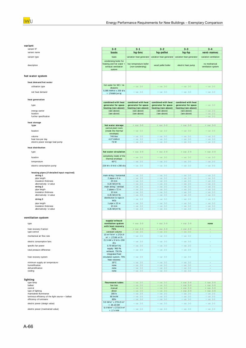
Energy Performance Requirements for New Buildings – Exemplary Comparison
variant
variant N° 3-0 3-1 3-2 3-3 3-4variant name basis hg-bnc hg-pellet hg-hp vent-nomec
variant type basis variation heat generator variation heat generator variation heat generator variation ventilation
description
condensing boiler for heating and hot water +
exhaust ventilation system
low temperature boiler (non-condensing)
wood pellet boiler electric heat pumpno mechanical
ventilation system
hot water system
heat demand hot water
utilisation typehot water for WC / no
showers= var. 3-0 = var. 3-0 = var. 3-0 = var. 3-0
net heat demand0,085 kWh/d x 200 d/a
= 17kWh/(m²a)= var. 3-0 = var. 3-0 = var. 3-0 = var. 3-0
heat generation
typecombined with heat generator for space heating (see above)
combined with heat generator for space heating (see above)
combined with heat generator for space heating (see above)
combined with heat generator for space heating (see above)
= var. 3-0
energy carrier (see above) (see above) (see above) (see above) = var. 3-0location (see above) (see above) (see above) (see above) = var. 3-0further specification - - - - = var. 3-0
heat storagetype hot water storage = var. 3-0 = var. 3-0 = var. 3-0 = var. 3-0
locationcentral plant room (inside the thermal
envelope)= var. 3-0 = var. 3-0 = var. 3-0 = var. 3-0
volume 749 liter = var. 3-0 = var. 3-0 = var. 3-0 = var. 3-0heat loss per day 4,07 kWh/d = var. 3-0 = var. 3-0 = var. 3-0 = var. 3-0electric power storage load pump 73 W = var. 3-0 = var. 3-0 = var. 3-0 = var. 3-0
heat distribution
type hot water circulation = var. 3-0 = var. 3-0 = var. 3-0 = var. 3-0
locationcompletely inside of the
thermal envelope= var. 3-0 = var. 3-0 = var. 3-0 = var. 3-0
temperature 60°C = var. 3-0 = var. 3-0 = var. 3-0 = var. 3-0
electric consumption pump 226 W x 9 h/d x 200 d/a = var. 3-0 = var. 3-0 = var. 3-0 = var. 3-0
heating pipes (if detailed input required)string 1 main string / horizontal = var. 3-0 = var. 3-0 = var. 3-0 = var. 3-0pipe length 2 pipes x 6 m = var. 3-0 = var. 3-0 = var. 3-0 = var. 3-0insulation thickness 20 mm = var. 3-0 = var. 3-0 = var. 3-0 = var. 3-0alternatively: U-value 0.20 W/(m²K) = var. 3-0 = var. 3-0 = var. 3-0 = var. 3-0string 2 main string / vertical = var. 3-0 = var. 3-0 = var. 3-0 = var. 3-0pipe length 2 pipes x 72 m = var. 3-0 = var. 3-0 = var. 3-0 = var. 3-0insulation thickness 10 mm = var. 3-0 = var. 3-0 = var. 3-0 = var. 3-0alternatively: U-value 0.26 W/(m²K) = var. 3-0 = var. 3-0 = var. 3-0 = var. 3-0
string 3distribution to taps in
WCs= var. 3-0 = var. 3-0 = var. 3-0 = var. 3-0
pipe length 1 pipe x 22 m = var. 3-0 = var. 3-0 = var. 3-0 = var. 3-0insulation thickness 10 mm = var. 3-0 = var. 3-0 = var. 3-0 = var. 3-0alternatively: U-value 0.26 W/(m²K) = var. 3-0 = var. 3-0 = var. 3-0 = var. 3-0
ventilation system
typesupply/exhaust
ventilation system with heat recovery
= var. 3-0 = var. 3-0 = var. 3-0 none
heat recovery fraction 75% = var. 3-0 = var. 3-0 = var. 3-0 -type control constant volume = var. 3-0 = var. 3-0 = var. 3-0 -
mechanical air flow rate10 m³/h/m² x 2724.9
m² = 27249 m³/h= var. 3-0 = var. 3-0 = var. 3-0 -
electric consumption fans21.5 kW x 9 h/d x 200
d/a= var. 3-0 = var. 3-0 = var. 3-0 -
specific fan power 0.79 W/(m³/h) = var. 3-0 = var. 3-0 = var. 3-0 -
total pressure differencesupply: 960 Pa
exhaust: 750 Pa= var. 3-0 = var. 3-0 = var. 3-0 -
heat recovery systemintegrated fluid
circulation system, 75% heat recovery
= var. 3-0 = var. 3-0 = var. 3-0 -
minimum supply air temperature 18°C = var. 3-0 = var. 3-0 = var. 3-0 -humidification none = var. 3-0 = var. 3-0 = var. 3-0 -dehumdification none = var. 3-0 = var. 3-0 = var. 3-0 -cooling none = var. 3-0 = var. 3-0 = var. 3-0 -
lightingtype lamp flourescent tubes = var. 3-0 = var. 3-0 = var. 3-0 = var. 3-0ballast low loss = var. 3-0 = var. 3-0 = var. 3-0 = var. 3-0control manual = var. 3-0 = var. 3-0 = var. 3-0 = var. 3-0type of lighting direct = var. 3-0 = var. 3-0 = var. 3-0 = var. 3-0maintained illuminance 300 lx = var. 3-0 = var. 3-0 = var. 3-0 = var. 3-0luminous efficiency of the light source + ballast 80 lm/W = var. 3-0 = var. 3-0 = var. 3-0 = var. 3-0efficiency of luminaire 80% = var. 3-0 = var. 3-0 = var. 3-0 = var. 3-0
electric power (design value)9.6 W/m² x 2724.9 m²
= 26.16 kW= var. 3-0 = var. 3-0 = var. 3-0 = var. 3-0
electric power (maintained value) 6.4 W/m² x 2724.9 m²
= 17.4 kW= var. 3-0 = var. 3-0 = var. 3-0 = var. 3-0
A-66

Energy Performance Requirements for New Buildings – Exemplary Comparison
Appendix 3d: Country sheets
A-67
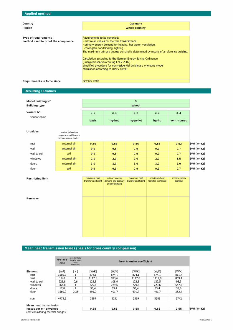
Applied method
CountryRegion
Requirements in force since
Resulting U-values
Model building N° 3Building type school
Variant N° 3-0 3-1 3-2 3-3 3-4variant name
basis hg-bnc hg-pellet hg-hp vent-nomec
U-values
roof 0,56 0,56 0,56 0,56 0,52 [W/(m²K)]
wall 0,9 0,8 0,9 0,9 0,7 [W/(m²K)]
wall to soil 0,9 0,8 0,9 0,9 0,7 [W/(m²K)]
windows 2,0 2,0 2,0 2,0 1,5 [W/(m²K)]
doors 3,0 3,0 3,0 3,0 2,0 [W/(m²K)]
floor 0,9 0,9 0,9 0,9 0,7 [W/(m²K)]
Restricting limit maximum heat transfer coefficient
primary energy demand and primary
energy demand
maximum heat transfer coefficient
maximum heat transfer coefficient
primary energy demand
Remarks
Mean heat transmission losses (basis for cross country comparison)
element area
correction factor (only for cross-
country comparison)
heat transfer coefficient
Element [m²] [ - ] [W/K] [W/K] [W/K] [W/K] [W/K]roof 1560,9 1 874,1 874,1 874,1 874,1 811,7wall 1242 1 1117,8 993,6 1117,8 1117,8 869,4wall to soil 226,8 0,6 122,5 108,9 122,5 122,5 95,3windows 364,8 1 729,6 729,6 729,6 729,6 547,2doors 17,8 1 53,4 53,4 53,4 53,4 35,6floor 1560,9 0,35 491,7 491,7 491,7 491,7 382,4
sum 4973,2 3389 3251 3389 3389 2742
Mean heat transmissionlosses per m² envelope 0,68 0,65 0,68 0,68 0,55 [W/(m²K)](not considering thermal bridges)
Requirements to be complied: - maximum values for thermal transmittance - primary energy demand for heating, hot water, ventilation, cooling/air-conditioning, lightingThe maximum primary energy demand is determined by means of a reference building.
Calculation according to the German Energy Saving Ordinance (Energieeinsparverordnung EnEV 2007)simplified procedure for non-residential buildings / one-zone modelcalculation according to DIN V 18599
Germanywhole country
U-value defined for temperature difference between room and ...
October 2007
Type of requirements / method used to proof the compliance
soil
external air
external air
soil
external air
external air
[building 3 - results.xls]de 03.12.2008 16:43
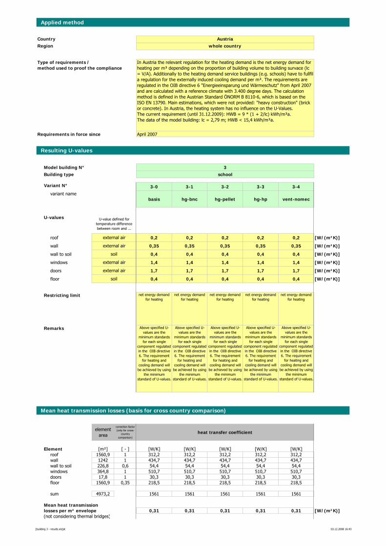
Applied method
CountryRegion
Requirements in force since
Resulting U-values
Model building N° 3Building type school
Variant N° 3-0 3-1 3-2 3-3 3-4variant name
basis hg-bnc hg-pellet hg-hp vent-nomec
U-values
roof 0,2 0,2 0,2 0,2 0,2 [W/(m²K)]
wall 0,35 0,35 0,35 0,35 0,35 [W/(m²K)]
wall to soil 0,4 0,4 0,4 0,4 0,4 [W/(m²K)]
windows 1,4 1,4 1,4 1,4 1,4 [W/(m²K)]
doors 1,7 1,7 1,7 1,7 1,7 [W/(m²K)]
floor 0,4 0,4 0,4 0,4 0,4 [W/(m²K)]
Restricting limit net energy demand for heating
net energy demand for heating
net energy demand for heating
net energy demand for heating
net energy demand for heating
Remarks Above specified U-values are the
minimum standards for each single
component regulated in the OIB directive 6. The requirement
for heating and cooling demand will be achieved by using
the minimum standard of U-values.
Above specified U-values are the
minimum standards for each single
component regulated in the OIB directive 6. The requirement
for heating and cooling demand will be achieved by using
the minimum standard of U-values.
Above specified U-values are the
minimum standards for each single
component regulated in the OIB directive 6. The requirement
for heating and cooling demand will be achieved by using
the minimum standard of U-values.
Above specified U-values are the
minimum standards for each single
component regulated in the OIB directive 6. The requirement
for heating and cooling demand will be achieved by using
the minimum standard of U-values.
Above specified U-values are the
minimum standards for each single
component regulated in the OIB directive 6. The requirement
for heating and cooling demand will be achieved by using
the minimum standard of U-values.
Mean heat transmission losses (basis for cross country comparison)
element area
correction factor (only for cross-
country comparison)
heat transfer coefficient
Element [m²] [ - ] [W/K] [W/K] [W/K] [W/K] [W/K]roof 1560,9 1 312,2 312,2 312,2 312,2 312,2wall 1242 1 434,7 434,7 434,7 434,7 434,7wall to soil 226,8 0,6 54,4 54,4 54,4 54,4 54,4windows 364,8 1 510,7 510,7 510,7 510,7 510,7doors 17,8 1 30,3 30,3 30,3 30,3 30,3floor 1560,9 0,35 218,5 218,5 218,5 218,5 218,5
sum 4973,2 1561 1561 1561 1561 1561
Mean heat transmissionlosses per m² envelope 0,31 0,31 0,31 0,31 0,31 [W/(m²K)](not considering thermal bridges)
In Austria the relevant regulation for the heating demand is the net energy demand for heating per m³ depending on the proportion of building volume to building survace (lc = V/A). Additionally to the heating demand service buildings (e.g. schools) have to fullfil a regulation for the externally induced cooling demand per m³. The requirements are regulated in the OIB directive 6 "Energieeinsparung und Wärmeschutz" from April 2007 and are calculated with a reference climate with 3.400 degree days. The calculation method is defined in the Austrian Standard ÖNORM B 8110-6, which is based on the ISO EN 13790. Main estimations, which were not provided: "heavy construction" (brick or concrete). In Austria, the heating system has no influence on the U-Values.The current requirement (until 31.12.2009): HWB = 9 * (1 + 2/lc) kWh/m³a. The data of the model building: lc = 2,79 m; HWB < 15,4 kWh/m³a.
Austriawhole country
U-value defined for temperature difference between room and ...
April 2007
Type of requirements / method used to proof the compliance
soil
external air
external air
soil
external air
external air
[building 3 - results.xls]at 03.12.2008 16:43
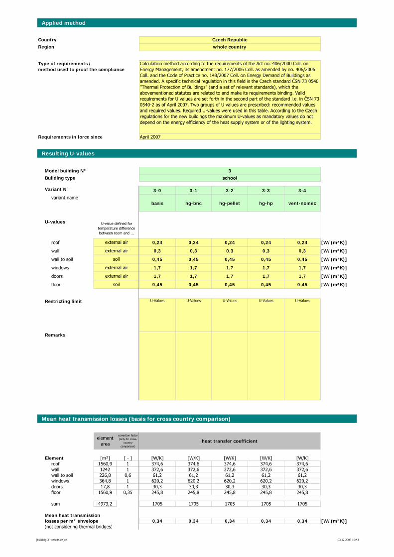
Applied method
CountryRegion
Requirements in force since
Resulting U-values
Model building N° 3Building type school
Variant N° 3-0 3-1 3-2 3-3 3-4variant name
basis hg-bnc hg-pellet hg-hp vent-nomec
U-values
roof 0,24 0,24 0,24 0,24 0,24 [W/(m²K)]
wall 0,3 0,3 0,3 0,3 0,3 [W/(m²K)]
wall to soil 0,45 0,45 0,45 0,45 0,45 [W/(m²K)]
windows 1,7 1,7 1,7 1,7 1,7 [W/(m²K)]
doors 1,7 1,7 1,7 1,7 1,7 [W/(m²K)]
floor 0,45 0,45 0,45 0,45 0,45 [W/(m²K)]
Restricting limit U-Values U-Values U-Values U-Values U-Values
Remarks
Mean heat transmission losses (basis for cross country comparison)
element area
correction factor (only for cross-
country comparison)
heat transfer coefficient
Element [m²] [ - ] [W/K] [W/K] [W/K] [W/K] [W/K]roof 1560,9 1 374,6 374,6 374,6 374,6 374,6wall 1242 1 372,6 372,6 372,6 372,6 372,6wall to soil 226,8 0,6 61,2 61,2 61,2 61,2 61,2windows 364,8 1 620,2 620,2 620,2 620,2 620,2doors 17,8 1 30,3 30,3 30,3 30,3 30,3floor 1560,9 0,35 245,8 245,8 245,8 245,8 245,8
sum 4973,2 1705 1705 1705 1705 1705
Mean heat transmissionlosses per m² envelope 0,34 0,34 0,34 0,34 0,34 [W/(m²K)](not considering thermal bridges)
Calculation method according to the requirements of the Act no. 406/2000 Coll. on Energy Management, its amendment no. 177/2006 Coll. as amended by no. 406/2006 Coll. and the Code of Practice no. 148/2007 Coll. on Energy Demand of Buildings as amended. A specific technical regulation in this field is the Czech standard ČSN 73 0540 "Thermal Protection of Buildings" (and a set of relevant standards), which the abovementioned statutes are related to and make its requirements binding. Valid requirements for U values are set forth in the second part of the standard i.e. in ČSN 73 0540-2 as of April 2007. Two groups of U values are prescribed: recommended values and required values. Required U-values were used in this table. According to the Czech regulations for the new buildings the maximum U-values as mandatory values do not depend on the energy efficiency of the heat supply system or of the lighting system.
Czech Republicwhole country
U-value defined for temperature difference between room and ...
April 2007
Type of requirements / method used to proof the compliance
soil
external air
external air
soil
external air
external air
[building 3 - results.xls]cz 03.12.2008 16:43
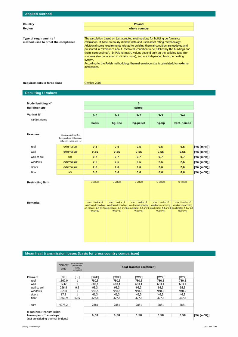
Applied method
CountryRegion
Requirements in force since
Resulting U-values
Model building N° 3Building type school
Variant N° 3-0 3-1 3-2 3-3 3-4variant name
basis hg-bnc hg-pellet hg-hp vent-nomec
U-values
roof 0,5 0,5 0,5 0,5 0,5 [W/(m²K)]
wall 0,55 0,55 0,55 0,55 0,55 [W/(m²K)]
wall to soil 0,7 0,7 0,7 0,7 0,7 [W/(m²K)]
windows 2,6 2,6 2,6 2,6 2,6 [W/(m²K)]
doors 2,6 2,6 2,6 2,6 2,6 [W/(m²K)]
floor 0,6 0,6 0,6 0,6 0,6 [W/(m²K)]
Restricting limit U-values U-values U-values U-values U-values
Remarks max. U-value of windows depending
on climate: 2.3 or 2.6 W/(m²K)
max. U-value of windows depending
on climate: 2.3 or 2.6 W/(m²K)
max. U-value of windows depending
on climate: 2.3 or 2.6 W/(m²K)
max. U-value of windows depending
on climate: 2.3 or 2.6 W/(m²K)
max. U-value of windows depending
on climate: 2.3 or 2.6 W/(m²K)
Mean heat transmission losses (basis for cross country comparison)
element area
correction factor (only for cross-
country comparison)
heat transfer coefficient
Element [m²] [ - ] [W/K] [W/K] [W/K] [W/K] [W/K]roof 1560,9 1 780,5 780,5 780,5 780,5 780,5wall 1242 1 683,1 683,1 683,1 683,1 683,1wall to soil 226,8 0,6 95,3 95,3 95,3 95,3 95,3windows 364,8 1 948,5 948,5 948,5 948,5 948,5doors 17,8 1 46,3 46,3 46,3 46,3 46,3floor 1560,9 0,35 327,8 327,8 327,8 327,8 327,8
sum 4973,2 2881 2881 2881 2881 2881
Mean heat transmissionlosses per m² envelope 0,58 0,58 0,58 0,58 0,58 [W/(m²K)](not considering thermal bridges)
The calculation based on just accepted methodology for building performance calculation. It base on hourly climatic data and used asset rating methodology. Additional some requirements related to building thermal condition are updated and presented in “Ordinance about technical condition to be fulfilled by the buildings and theirs surroundings“. In Poland max U values depend only on the building type (for windows also on location in climatic zone), and are independed from the heating system. According to the Polish methodology thermal envelope size is calculatedd on external dimensions.
Polandwhole country
U-value defined for temperature difference between room and ...
October 2002
Type of requirements / method used to proof the compliance
soil
external air
external air
soil
external air
external air
[building 3 - results.xls]pl 03.12.2008 16:43
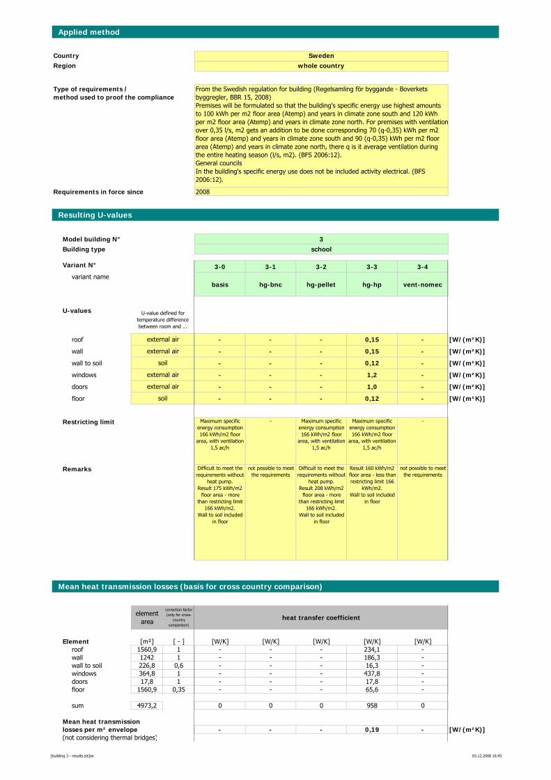
Applied method
CountryRegion
Requirements in force since
Resulting U-values
Model building N° 3Building type school
Variant N° 3-0 3-1 3-2 3-3 3-4variant name
basis hg-bnc hg-pellet hg-hp vent-nomec
U-values
roof - - - 0,15 - [W/(m²K)]
wall - - - 0,15 - [W/(m²K)]
wall to soil - - - 0,12 - [W/(m²K)]
windows - - - 1,2 - [W/(m²K)]
doors - - - 1,0 - [W/(m²K)]
floor - - - 0,12 - [W/(m²K)]
Restricting limit Maximum specific energy consumption 166 kWh/m2 floor
area, with ventilation 1,5 ac/h
- Maximum specific energy consumption 166 kWh/m2 floor
area, with ventilation 1,5 ac/h
Maximum specific energy consumption 166 kWh/m2 floor
area, with ventilation 1,5 ac/h
-
Remarks Difficult to meet the requirements without
heat pump. Result 175 kWh/m2
floor area - more than restricting limit
166 kWh/m2.Wall to soil included
in floor
not possible to meet the requirements
Difficult to meet the requirements without
heat pump. Result 208 kWh/m2
floor area - more than restricting limit
166 kWh/m2.Wall to soil included
in floor
Result 160 kWh/m2 floor area - less than restricting limit 166
kWh/m2.Wall to soil included
in floor
not possible to meet the requirements
Mean heat transmission losses (basis for cross country comparison)
element area
correction factor (only for cross-
country comparison)
heat transfer coefficient
Element [m²] [ - ] [W/K] [W/K] [W/K] [W/K] [W/K]roof 1560,9 1 - - - 234,1 -wall 1242 1 - - - 186,3 -wall to soil 226,8 0,6 - - - 16,3 -windows 364,8 1 - - - 437,8 -doors 17,8 1 - - - 17,8 -floor 1560,9 0,35 - - - 65,6 -
sum 4973,2 0 0 0 958 0
Mean heat transmissionlosses per m² envelope - - - 0,19 - [W/(m²K)](not considering thermal bridges)
From the Swedish regulation for building (Regelsamling för byggande - Boverkets byggregler, BBR 15, 2008) Premises will be formulated so that the building's specific energy use highest amounts to 100 kWh per m2 floor area (Atemp) and years in climate zone south and 120 kWh per m2 floor area (Atemp) and years in climate zone north. For premises with ventilationover 0,35 l/s, m2 gets an addition to be done corresponding 70 (q-0,35) kWh per m2 floor area (Atemp) and years in climate zone south and 90 (q-0,35) kWh per m2 floor area (Atemp) and years in climate zone north, there q is it average ventilation during the entire heating season (l/s, m2). (BFS 2006:12). General councilsIn the building's specific energy use does not be included activity electrical. (BFS 2006:12).
Swedenwhole country
U-value defined for temperature difference between room and ...
2008
Type of requirements / method used to proof the compliance
soil
external air
external air
soil
external air
external air
[building 3 - results.xls]se 03.12.2008 16:43
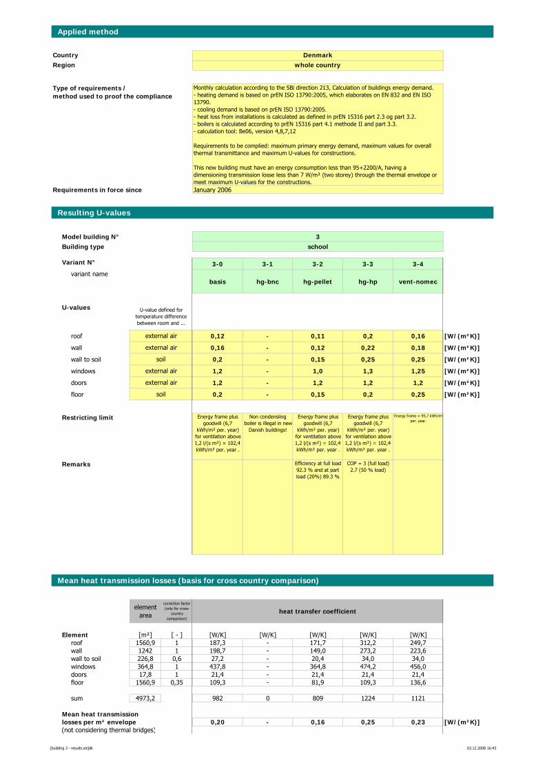
Applied method
CountryRegion
Requirements in force since
Resulting U-values
Model building N° 3Building type school
Variant N° 3-0 3-1 3-2 3-3 3-4variant name
basis hg-bnc hg-pellet hg-hp vent-nomec
U-values
roof 0,12 - 0,11 0,2 0,16 [W/(m²K)]
wall 0,16 - 0,12 0,22 0,18 [W/(m²K)]
wall to soil 0,2 - 0,15 0,25 0,25 [W/(m²K)]
windows 1,2 - 1,0 1,3 1,25 [W/(m²K)]
doors 1,2 - 1,2 1,2 1,2 [W/(m²K)]
floor 0,2 - 0,15 0,2 0,25 [W/(m²K)]
Restricting limit Energy frame plus goodwill (6,7
kWh/m² per. year) for ventilation above 1,2 l/(s m²) = 102,4 kWh/m² per. year .
Non condensiing boiler is illegal in new
Danish buildings!
Energy frame plus goodwill (6,7
kWh/m² per. year) for ventilation above 1,2 l/(s m²) = 102,4 kWh/m² per. year .
Energy frame plus goodwill (6,7
kWh/m² per. year) for ventilation above 1,2 l/(s m²) = 102,4 kWh/m² per. year .
Energy frame = 95,7 kWh/m²per. year.
Remarks Efficiency at full load 92.3 % and at part load (20%) 89.3 %
COP = 3 (full load) 2.7 (50 % load)
Mean heat transmission losses (basis for cross country comparison)
element area
correction factor (only for cross-
country comparison)
heat transfer coefficient
Element [m²] [ - ] [W/K] [W/K] [W/K] [W/K] [W/K]roof 1560,9 1 187,3 - 171,7 312,2 249,7wall 1242 1 198,7 - 149,0 273,2 223,6wall to soil 226,8 0,6 27,2 - 20,4 34,0 34,0windows 364,8 1 437,8 - 364,8 474,2 456,0doors 17,8 1 21,4 - 21,4 21,4 21,4floor 1560,9 0,35 109,3 - 81,9 109,3 136,6
sum 4973,2 982 0 809 1224 1121
Mean heat transmissionlosses per m² envelope 0,20 - 0,16 0,25 0,23 [W/(m²K)](not considering thermal bridges)
Monthly calculation according to the SBi direction 213, Calculation of buildings energy demand. - heating demand is based on prEN ISO 13790:2005, which elaborates on EN 832 and EN ISO 13790.- cooling demand is based on prEN ISO 13790:2005.- heat loss from installations is calculated as defined in prEN 15316 part 2.3 og part 3.2.- boilers is calculated according to prEN 15316 part 4.1 methode II and part 3.3. - calculation tool: Be06, version 4,8,7,12
Requirements to be complied: maximum primary energy demand, maximum values for overall thermal transmittance and maximum U-values for constructions.
This new building must have an energy consumption less than 95+2200/A, having a dimensioning transmission losse less than 7 W/m² (two storey) through the thermal envelope or meet maximum U-values for the constructions.
Denmarkwhole country
U-value defined for temperature difference between room and ...
January 2006
Type of requirements / method used to proof the compliance
soil
external air
external air
soil
external air
external air
[building 3 - results.xls]dk 03.12.2008 16:43
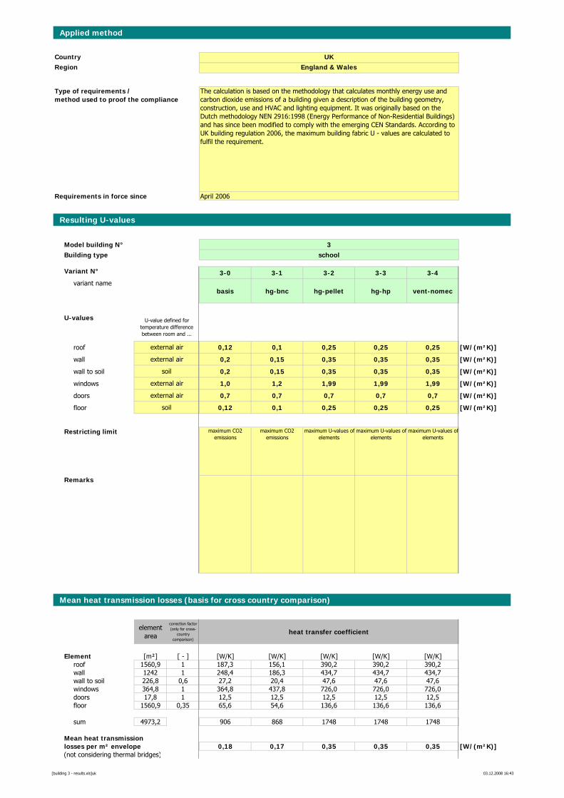
Applied method
CountryRegion
Requirements in force since
Resulting U-values
Model building N° 3Building type school
Variant N° 3-0 3-1 3-2 3-3 3-4variant name
basis hg-bnc hg-pellet hg-hp vent-nomec
U-values
roof 0,12 0,1 0,25 0,25 0,25 [W/(m²K)]
wall 0,2 0,15 0,35 0,35 0,35 [W/(m²K)]
wall to soil 0,2 0,15 0,35 0,35 0,35 [W/(m²K)]
windows 1,0 1,2 1,99 1,99 1,99 [W/(m²K)]
doors 0,7 0,7 0,7 0,7 0,7 [W/(m²K)]
floor 0,12 0,1 0,25 0,25 0,25 [W/(m²K)]
Restricting limit maximum CO2 emissions
maximum CO2 emissions
maximum U-values ofelements
maximum U-values ofelements
maximum U-values ofelements
Remarks
Mean heat transmission losses (basis for cross country comparison)
element area
correction factor (only for cross-
country comparison)
heat transfer coefficient
Element [m²] [ - ] [W/K] [W/K] [W/K] [W/K] [W/K]roof 1560,9 1 187,3 156,1 390,2 390,2 390,2wall 1242 1 248,4 186,3 434,7 434,7 434,7wall to soil 226,8 0,6 27,2 20,4 47,6 47,6 47,6windows 364,8 1 364,8 437,8 726,0 726,0 726,0doors 17,8 1 12,5 12,5 12,5 12,5 12,5floor 1560,9 0,35 65,6 54,6 136,6 136,6 136,6
sum 4973,2 906 868 1748 1748 1748
Mean heat transmissionlosses per m² envelope 0,18 0,17 0,35 0,35 0,35 [W/(m²K)](not considering thermal bridges)
The calculation is based on the methodology that calculates monthly energy use and carbon dioxide emissions of a building given a description of the building geometry, construction, use and HVAC and lighting equipment. It was originally based on the Dutch methodology NEN 2916:1998 (Energy Performance of Non-Residential Buildings) and has since been modified to comply with the emerging CEN Standards. According to UK building regulation 2006, the maximum building fabric U - values are calculated to fulfil the requirement.
UKEngland & Wales
U-value defined for temperature difference between room and ...
April 2006
Type of requirements / method used to proof the compliance
soil
external air
external air
soil
external air
external air
[building 3 - results.xls]uk 03.12.2008 16:43
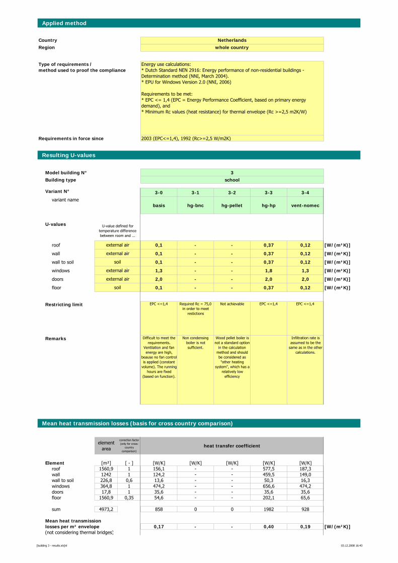
Applied method
CountryRegion
Requirements in force since
Resulting U-values
Model building N° 3Building type school
Variant N° 3-0 3-1 3-2 3-3 3-4variant name
basis hg-bnc hg-pellet hg-hp vent-nomec
U-values
roof 0,1 - - 0,37 0,12 [W/(m²K)]
wall 0,1 - - 0,37 0,12 [W/(m²K)]
wall to soil 0,1 - - 0,37 0,12 [W/(m²K)]
windows 1,3 - - 1,8 1,3 [W/(m²K)]
doors 2,0 - - 2,0 2,0 [W/(m²K)]
floor 0,1 - - 0,37 0,12 [W/(m²K)]
Restricting limit EPC <=1,4 Required Rc = 75,0 in order to meet
restictions
Not achievable EPC <=1,4 EPC <=1,4
Remarks Difficult to meet the requirements.
Ventilation and fan energy are high,
beause no fan control is applied (constant
volume). The running hours are fixed
(based on function).
Non condensing boiler is not sufficient.
Wood pellet boiler is not a standard option
in the calculation method and should be considered as "other heating
system", which has a relatively low
efficiency
Infiltration rate is assumed to be the
same as in the other calculations.
Mean heat transmission losses (basis for cross country comparison)
element area
correction factor (only for cross-
country comparison)
heat transfer coefficient
Element [m²] [ - ] [W/K] [W/K] [W/K] [W/K] [W/K]roof 1560,9 1 156,1 - - 577,5 187,3wall 1242 1 124,2 - - 459,5 149,0wall to soil 226,8 0,6 13,6 - - 50,3 16,3windows 364,8 1 474,2 - - 656,6 474,2doors 17,8 1 35,6 - - 35,6 35,6floor 1560,9 0,35 54,6 - - 202,1 65,6
sum 4973,2 858 0 0 1982 928
Mean heat transmissionlosses per m² envelope 0,17 - - 0,40 0,19 [W/(m²K)](not considering thermal bridges)
Energy use calculations:* Dutch Standard NEN 2916: Energy performance of non-residential buildings - Determination method (NNI, March 2004).* EPU for Windows Version 2.0 (NNI, 2006)
Requirements to be met:* EPC <= 1,4 (EPC = Energy Performance Coefficient, based on primary energy demand), and* Minimum Rc values (heat resistance) for thermal envelope (Rc >=2,5 m2K/W)
Netherlandswhole country
U-value defined for temperature difference between room and ...
2003 (EPC<=1,4), 1992 (Rc>=2,5 W/m2K)
Type of requirements / method used to proof the compliance
soil
external air
external air
soil
external air
external air
[building 3 - results.xls]nl 03.12.2008 16:43
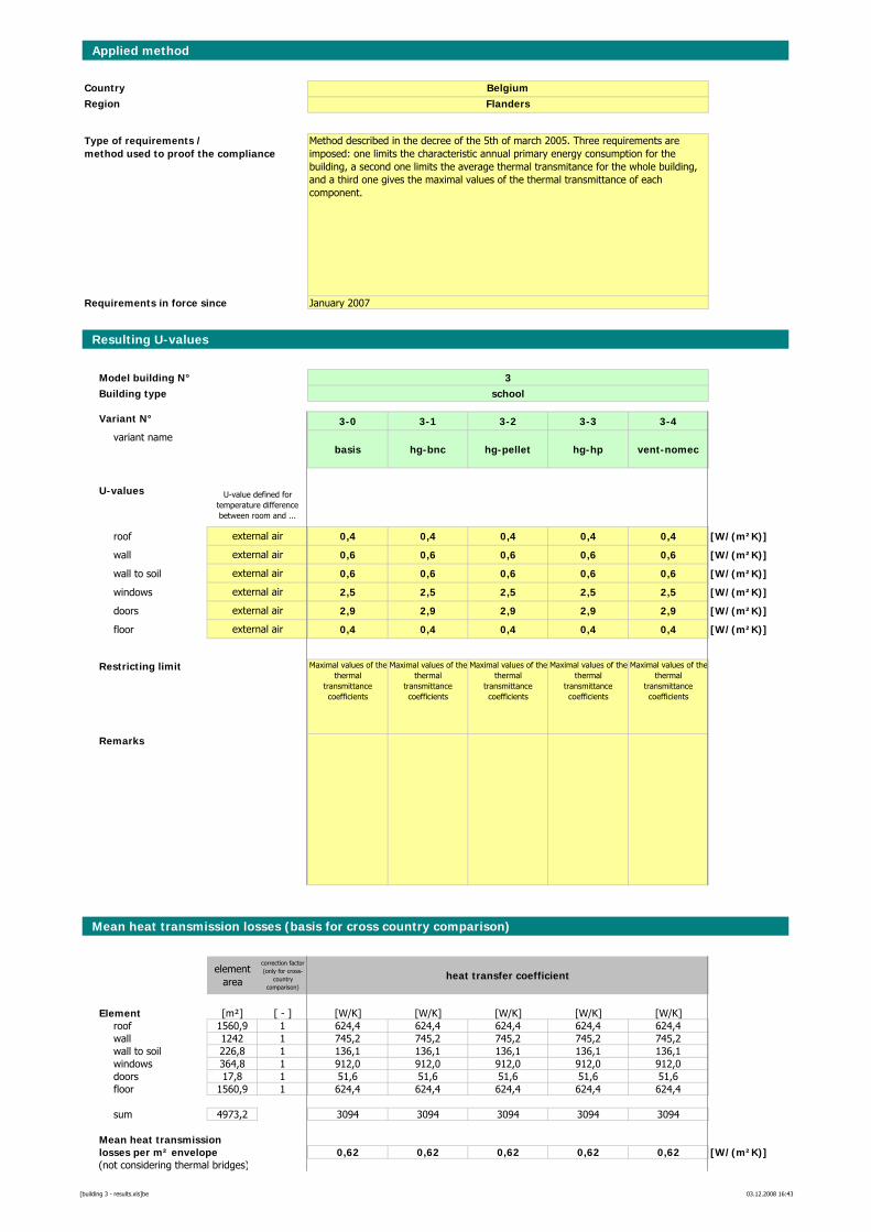
Applied method
CountryRegion
Requirements in force since
Resulting U-values
Model building N° 3Building type school
Variant N° 3-0 3-1 3-2 3-3 3-4variant name
basis hg-bnc hg-pellet hg-hp vent-nomec
U-values
roof 0,4 0,4 0,4 0,4 0,4 [W/(m²K)]
wall 0,6 0,6 0,6 0,6 0,6 [W/(m²K)]
wall to soil 0,6 0,6 0,6 0,6 0,6 [W/(m²K)]
windows 2,5 2,5 2,5 2,5 2,5 [W/(m²K)]
doors 2,9 2,9 2,9 2,9 2,9 [W/(m²K)]
floor 0,4 0,4 0,4 0,4 0,4 [W/(m²K)]
Restricting limit Maximal values of the thermal
transmittance coefficients
Maximal values of the thermal
transmittance coefficients
Maximal values of the thermal
transmittance coefficients
Maximal values of the thermal
transmittance coefficients
Maximal values of the thermal
transmittance coefficients
Remarks
Mean heat transmission losses (basis for cross country comparison)
element area
correction factor (only for cross-
country comparison)
heat transfer coefficient
Element [m²] [ - ] [W/K] [W/K] [W/K] [W/K] [W/K]roof 1560,9 1 624,4 624,4 624,4 624,4 624,4wall 1242 1 745,2 745,2 745,2 745,2 745,2wall to soil 226,8 1 136,1 136,1 136,1 136,1 136,1windows 364,8 1 912,0 912,0 912,0 912,0 912,0doors 17,8 1 51,6 51,6 51,6 51,6 51,6floor 1560,9 1 624,4 624,4 624,4 624,4 624,4
sum 4973,2 3094 3094 3094 3094 3094
Mean heat transmissionlosses per m² envelope 0,62 0,62 0,62 0,62 0,62 [W/(m²K)](not considering thermal bridges)
Method described in the decree of the 5th of march 2005. Three requirements are imposed: one limits the characteristic annual primary energy consumption for the building, a second one limits the average thermal transmitance for the whole building, and a third one gives the maximal values of the thermal transmittance of each component.
BelgiumFlanders
U-value defined for temperature difference between room and ...
January 2007
Type of requirements / method used to proof the compliance
external air
external air
external air
external air
external air
external air
[building 3 - results.xls]be 03.12.2008 16:43
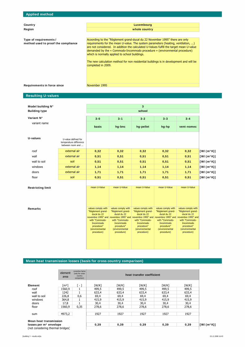
Applied method
CountryRegion
Requirements in force since
Resulting U-values
Model building N° 3Building type school
Variant N° 3-0 3-1 3-2 3-3 3-4variant name
basis hg-bnc hg-pellet hg-hp vent-nomec
U-values
roof 0,32 0,32 0,32 0,32 0,32 [W/(m²K)]
wall 0,51 0,51 0,51 0,51 0,51 [W/(m²K)]
wall to soil 0,51 0,51 0,51 0,51 0,51 [W/(m²K)]
windows 1,14 1,14 1,14 1,14 1,14 [W/(m²K)]
doors 1,71 1,71 1,71 1,71 1,71 [W/(m²K)]
floor 0,51 0,51 0,51 0,51 0,51 [W/(m²K)]
Restricting limit mean U-Value mean U-Value mean U-Value mean U-Value mean U-Value
Remarks values comply with "Règlement grand-
ducal du 22 novembre 1995" and
with "Commodo-Incommodo procedure"
(environmental procedure)
values comply with "Règlement grand-
ducal du 22 novembre 1995" and
with "Commodo-Incommodo procedure"
(environmental procedure)
values comply with "Règlement grand-
ducal du 22 novembre 1995" and
with "Commodo-Incommodo procedure"
(environmental procedure)
values comply with "Règlement grand-
ducal du 22 novembre 1995" and
with "Commodo-Incommodo procedure"
(environmental procedure)
values comply with "Règlement grand-
ducal du 22 novembre 1995" and
with "Commodo-Incommodo procedure"
(environmental procedure)
Mean heat transmission losses (basis for cross country comparison)
element area
correction factor (only for cross-
country comparison)
heat transfer coefficient
Element [m²] [ - ] [W/K] [W/K] [W/K] [W/K] [W/K]roof 1560,9 1 499,5 499,5 499,5 499,5 499,5wall 1242 1 633,4 633,4 633,4 633,4 633,4wall to soil 226,8 0,6 69,4 69,4 69,4 69,4 69,4windows 364,8 1 415,9 415,9 415,9 415,9 415,9doors 17,8 1 30,4 30,4 30,4 30,4 30,4floor 1560,9 0,35 278,6 278,6 278,6 278,6 278,6
sum 4973,2 1927 1927 1927 1927 1927
Mean heat transmissionlosses per m² envelope 0,39 0,39 0,39 0,39 0,39 [W/(m²K)](not considering thermal bridges)
Acoording to the "Règlement grand-ducal du 22 November 1995" there are only requirements for the mean U-value. The system parameters (heating, ventilation, ...) are not considered. In addition the calculated U-Values fulfill the target mean U-value demanded by the « Commodo-Incommodo procedure » (environmental procedure) which is normally applied to school buildings.
The new calculation method for non residential buildings is in development and will be completed in 2009.
Luxembourgwhole country
U-value defined for temperature difference between room and ...
November 1995
Type of requirements / method used to proof the compliance
soil
external air
external air
soil
external air
external air
[building 3 - results.xls]lu 03.12.2008 16:43
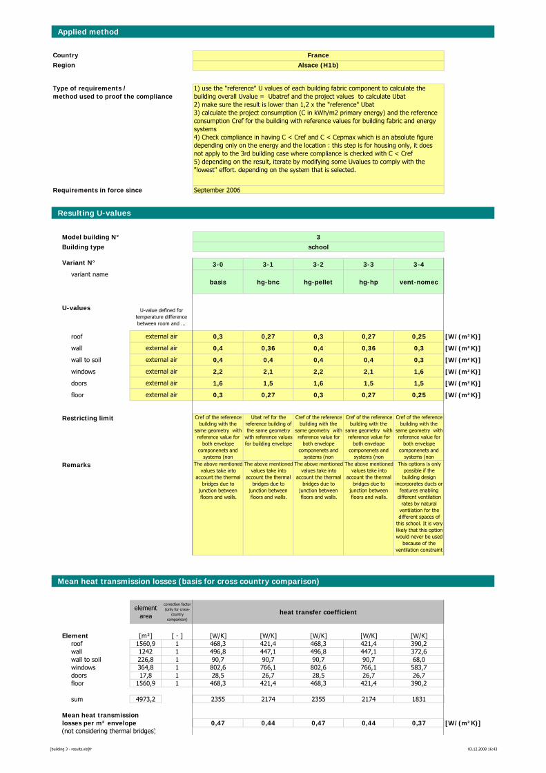
Applied method
CountryRegion
Requirements in force since
Resulting U-values
Model building N° 3Building type school
Variant N° 3-0 3-1 3-2 3-3 3-4variant name
basis hg-bnc hg-pellet hg-hp vent-nomec
U-values
roof 0,3 0,27 0,3 0,27 0,25 [W/(m²K)]
wall 0,4 0,36 0,4 0,36 0,3 [W/(m²K)]
wall to soil 0,4 0,4 0,4 0,4 0,3 [W/(m²K)]
windows 2,2 2,1 2,2 2,1 1,6 [W/(m²K)]
doors 1,6 1,5 1,6 1,5 1,5 [W/(m²K)]
floor 0,3 0,27 0,3 0,27 0,25 [W/(m²K)]
Restricting limit Cref of the reference building with the
same geometry with reference value for
both envelope componenets and
systems (non
Ubat ref for the reference building of the same geometry
with reference values for building envelope
Cref of the reference building with the
same geometry with reference value for
both envelope componenets and
systems (non
Cref of the reference building with the
same geometry with reference value for
both envelope componenets and
systems (non
Cref of the reference building with the
same geometry with reference value for
both envelope componenets and
systems (non
Remarks The above mentioned values take into
account the thermal bridges due to
junction between floors and walls.
The above mentioned values take into
account the thermal bridges due to
junction between floors and walls.
The above mentioned values take into
account the thermal bridges due to
junction between floors and walls.
The above mentioned values take into
account the thermal bridges due to
junction between floors and walls.
This options is only possible if the building design
incorporates ducts or features enabling
different ventilation rates by natural
ventilation for the different spaces of
this school. It is very likely that this option would never be used
because of the ventilation constraint
Mean heat transmission losses (basis for cross country comparison)
element area
correction factor (only for cross-
country comparison)
heat transfer coefficient
Element [m²] [ - ] [W/K] [W/K] [W/K] [W/K] [W/K]roof 1560,9 1 468,3 421,4 468,3 421,4 390,2wall 1242 1 496,8 447,1 496,8 447,1 372,6wall to soil 226,8 1 90,7 90,7 90,7 90,7 68,0windows 364,8 1 802,6 766,1 802,6 766,1 583,7doors 17,8 1 28,5 26,7 28,5 26,7 26,7floor 1560,9 1 468,3 421,4 468,3 421,4 390,2
sum 4973,2 2355 2174 2355 2174 1831
Mean heat transmissionlosses per m² envelope 0,47 0,44 0,47 0,44 0,37 [W/(m²K)](not considering thermal bridges)
external air
external air
external air
external air
external air
external air
1) use the "reference" U values of each building fabric component to calculate the building overall Uvalue = Ubatref and the project values to calculate Ubat2) make sure the result is lower than 1,2 x the "reference" Ubat3) calculate the project consumption (C in kWh/m2 primary energy) and the reference consumption Cref for the building with reference values for building fabric and energy systems4) Check compliance in having C < Cref and C < Cepmax which is an absolute figure depending only on the energy and the location : this step is for housing only, it does not apply to the 3rd building case where compliance is checked with C < Cref5) depending on the result, iterate by modifying some Uvalues to comply with the "lowest" effort. depending on the system that is selected.
FranceAlsace (H1b)
U-value defined for temperature difference between room and ...
September 2006
Type of requirements / method used to proof the compliance
[building 3 - results.xls]fr 03.12.2008 16:43
Recommended