ABS submersible sewage pump AFP 0831-2046
Text var Type testedand monitored
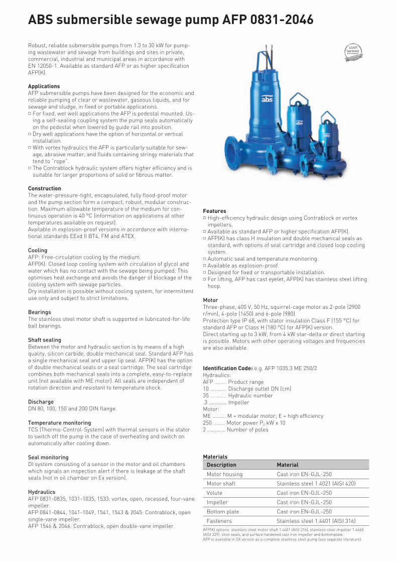
Robust, reliable submersible pumps from 1.3 to 30 kW for pump-ing wastewater and sewage from buildings and sites in private, commercial, industrial and municipal areas in accordance with EN 12050-1. Available as standard AFP or as higher specification AFP(K).
ApplicationsAFP submersible pumps have been designed for the economic and reliable pumping of clear or wastewater, gaseous liquids, and for sewage and sludge, in fixed or portable applications.* For fixed, wet well applications the AFP is pedestal mounted. Us-
ing a self-sealing coupling system the pump seals automatically on the pedestal when lowered by guide rail into position.
* Dry well applications have the option of horizontal or vertical installation.
* With vortex hydraulics the AFP is particularly suitable for sew-age, abrasive matter, and fluids containing stringy materials that tend to ”rope”.
* The Contrablock hydraulic system offers higher efficiency and is suitable for larger proportions of solid or fibrous matter.
ConstructionThe water-pressure-tight, encapsulated, fully flood-proof motor and the pump section form a compact, robust, modular construc-tion. Maximum allowable temperature of the medium for con-tinuous operation is 40 °C (information on applications at other temperatures available on request).Available in explosion-proof versions in accordance with interna-tional standards EExd II BT4, FM and ATEX.
CoolingAFP: Free-circulation cooling by the medium.AFP(K): Closed loop cooling system with circulation of glycol and water which has no contact with the sewage being pumped. This optimises heat exchange and avoids the danger of blockage of the cooling system with sewage particles.Dry installation is possible without cooling system, for intermittent use only and subject to strict limitations.
BearingsThe stainless steel motor shaft is supported in lubricated-for-life ball bearings.
Shaft sealingBetween the motor and hydraulic section is by means of a high quality, silicon carbide, double mechanical seal. Standard AFP has a single mechanical seal and upper lip seal. AFP(K) has the option of double mechanical seals or a seal cartridge. The seal cartridge combines both mechanical seals into a complete, easy-to-replace unit (not available with ME motor). All seals are independent of rotation direction and resistant to temperature shock.
DischargeDN 80, 100, 150 and 200 DIN flange.
Temperature monitoringTCS (Thermo-Control-System) with thermal sensors in the stator to switch off the pump in the case of overheating and switch on automatically after cooling down.
Seal monitoringDI system consisting of a sensor in the motor and oil chambers which signals an inspection alert if there is leakage at the shaft seals (not in oil chamber on Ex version).
HydraulicsAFP 0831-0835, 1031-1035, 1533: vortex, open, recessed, four-vane impeller.AFP 0841-0844, 1041-1049, 1541, 1543 & 2045: Contrablock, open single-vane impeller.AFP 1546 & 2046: Contrablock, open double-vane impeller.
Features* High-efficiency hydraulic design using Contrablock or vortex
impellers.* Available as standard AFP or higher specification AFP(K).* AFP(K) has class H insulation and double mechanical seals as
standard, with options of seal cartridge and closed loop cooling system.
* Automatic seal and temperature monitoring.* Available as explosion-proof.* Designed for fixed or transportable installation.* For lifting, AFP has cast eyelet, AFP(K) has stainless steel lifting
hoop.
MotorThree-phase, 400 V, 50 Hz, squirrel-cage motor as 2-pole (2900 r/min), 4-pole (1450) and 6-pole (980). Protection type IP 68, with stator insulation Class F (155 °C) for standard AFP or Class H (180 °C) for AFP(K) version.Direct starting up to 3 kW; from 4 kW star-delta or direct starting is possible. Motors with other operating voltages and frequencies are also available.
Identification Code: e.g. AFP 1035.3 ME 250/2Hydraulics:AFP ........ Product range10 ........... Discharge outlet DN (cm) 35 ........... Hydraulic number .3 ............ ImpellerMotor:ME ......... M = modular motor; E = high efficiency250 ........ Motor power P2 kW x 102 ............ Number of poles
MaterialsDescription Material
Motor housing Cast iron EN-GJL-250
Motor shaft Stainless steel 1.4021 (AISI 420)
Volute Cast iron EN-GJL-250
Impeller Cast iron EN-GJL-250
Bottom plate Cast iron EN-GJL-250
Fasteners Stainless steel 1.4401 (AISI 316)AFP(K) options: stainless steel motor shaft 1.4401 (AISI 316), stainless steel impeller 1.4460 (AISI 329), viton seals, and surface hardened cast iron impeller and bottomplate.AFP is available in SX version as a complete stainless steel pump (see separate literature).
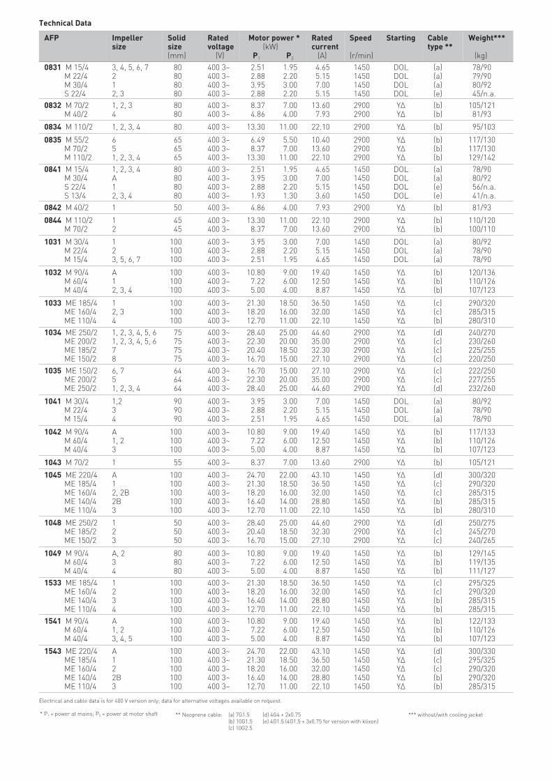
* P1 = power at mains; P2 = power at motor shaft ** Neoprene cable: (a) 7G1.5(b) 10G1.5(c) 10G2.5
(d) 4G4 + 2x0.75(e) 4G1.5 (4G1.5 + 3x0.75 for version with klixon)
AFP Impellersize
Solidsize(mm)
Ratedvoltage (V)
Motor power * (kW) P1 P2
Rated current (A)
Speed
(r/min)
Starting Cabletype **
Weight***
(kg)0831 M 15/4 M 22/4 M 30/4 S 22/4
3, 4, 5, 6, 7212, 3
80 80 80 80
400 3~400 3~400 3~400 3~
2.51 1.95 2.88 2.20 3.95 3.00 2.88 2.20
4.65 5.15 7.00 5.15
1450 1450 1450 1450
DOLDOLDOLDOL
(a) (a) (a) (e)
78/90 79/90 80/92 45/n.a.
0832 M 70/2 M 40/2
1, 2, 34
80 80
400 3~400 3~
8.37 7.00 4.86 4.00
13.60 7.93
2900 2900
YΔYΔ
(b) (b)
105/121 81/93
0834 M 110/2 1, 2, 3, 4 80 400 3~ 13.30 11.00 22.10 2900 YΔ (b) 95/103
0835 M 55/2 M 70/2 M 110/2
651, 2, 3, 4
65 65 65
400 3~400 3~400 3~
6.49 5.50 8.37 7.00 13.30 11.00
10.4013.6022.10
2900 2900 2900
YΔYΔYΔ
(b) (b) (b)
117/130117/130129/142
0841 M 15/4 M 30/4 S 22/4 S 13/4
1, 2, 3, 4A12, 3, 4
80 80 80 80
400 3~400 3~400 3~400 3~
2.51 1.95 3.95 3.00 2.88 2.20 1.93 1.30
4.65 7.00 5.15 3.60
1450 1450 1450 1450
DOLDOLDOLDOL
(a) (a) (e) (e)
78/90 80/92 56/n.a. 41/n.a.
0842 M 40/2 1 50 400 3~ 4.86 4.00 7.93 2900 YΔ (b) 81/93
0844 M 110/2 M 70/2
12
45 45
400 3~400 3~
13.30 11.00 8.37 7.00
22.1013.60
2900 2900
YΔYΔ
(b) (b)
110/120100/110
1031 M 30/4 M 22/4 M 15/4
123, 5, 6, 7
100 100 100
400 3~400 3~400 3~
3.95 3.00 2.88 2.20 2.51 1.95
7.00 5.15 4.65
1450 1450 1450
DOLDOLDOL
(a) (a) (a)
80/92 78/90 78/90
1032 M 90/4 M 60/4 M 40/4
A12, 3, 4
100 100 100
400 3~400 3~400 3~
10.80 9.00 7.22 6.00 5.00 4.00
19.4012.50 8.87
1450 1450 1450
YΔYΔYΔ
(b) (b) (b)
120/136110/126107/123
1033 ME 185/4 ME 160/4 ME 110/4
12, 34
100 100 100
400 3~400 3~400 3~
21.30 18.50 18.20 16.00 12.70 11.00
36.5032.0022.10
1450 1450 1450
YΔYΔYΔ
(c) (c) (b)
290/320285/315280/310
1034 ME 250/2 ME 200/2 ME 185/2 ME 150/2
1, 2, 3, 4, 5, 61, 2, 3, 4, 5, 678
75 75 75 75
400 3~400 3~400 3~400 3~
28.40 25.00 22.30 20.00 20.40 18.50 16.70 15.00
44.6035.0032.3027.10
2900 2900 2900 2900
YΔYΔYΔYΔ
(d) (c) (c) (c)
240/270230/260225/255220/250
1035 ME 150/2 ME 200/2 ME 250/2
6, 751, 2, 3, 4
64 64 64
400 3~400 3~400 3~
16.70 15.00 22.30 20.00 28.40 25.00
27.1035.0044.60
2900 2900 2900
YΔYΔYΔ
(c) (c) (d)
222/250227/255232/260
1041 M 30/4 M 22/4 M 15/4
1,234
90 90 90
400 3~400 3~400 3~
3.95 3.00 2.88 2.20 2.51 1.95
7.00 5.15 4.65
1450 1450 1450
DOLDOLDOL
(a) (a) (a)
80/92 78/90 78/90
1042 M 90/4 M 60/4 M 40/4
A1, 23
100 100 100
400 3~400 3~400 3~
10.80 9.00 7.22 6.00 5.00 4.00
19.4012.50 8.87
1450 1450 1450
YΔYΔYΔ
(b) (b) (b)
117/133110/126107/123
1043 M 70/2 1 55 400 3~ 8.37 7.00 13.60 2900 YΔ (b) 105/121
1045 ME 220/4 ME 185/4 ME 160/4 ME 140/4 ME 110/4
A12, 2B2B3
100 100 100 100 100
400 3~400 3~400 3~400 3~400 3~
24.70 22.00 21.30 18.50 18.20 16.00 16.40 14.00 12.70 11.00
43.1036.5032.0028.8022.10
1450 1450 1450 1450 1450
YΔYΔYΔYΔYΔ
(d) (c) (c) (b) (b)
300/320290/320285/315285/315280/310
1048 ME 250/2 ME 185/2 ME 150/2
123
50 50 50
400 3~400 3~400 3~
28.40 25.00 20.40 18.50 16.70 15.00
44.6032.3027.10
2900 2900 2900
YΔYΔYΔ
(d) (c) (c)
250/275245/270240/265
1049 M 90/4 M 60/4 M 40/4
A, 234
80 80 80
400 3~400 3~400 3~
10.80 9.00 7.22 6.00 5.00 4.00
19.4012.50 8.87
1450 1450 1450
YΔYΔYΔ
(b) (b) (b)
129/145119/135111/127
1533 ME 185/4 ME 160/4 ME 140/4 ME 110/4
1234
100 100 100 100
400 3~400 3~400 3~400 3~
21.30 18.50 18.20 16.00 16.40 14.00 12.70 11.00
36.5032.0028.8022.10
1450 1450 1450 1450
YΔYΔYΔYΔ
(c) (c) (b) (b)
295/325290/320285/315285/315
1541 M 90/4 M 60/4 M 40/4
A1, 23, 4, 5
100 100 100
400 3~400 3~400 3~
10.80 9.00 7.22 6.00 5.00 4.00
19.4012.50 8.87
1450 1450 1450
YΔYΔYΔ
(b) (b) (b)
122/133110/126107/123
1543 ME 220/4 ME 185/4 ME 160/4 ME 140/4 ME 110/4
A122B3
100 100 100 100 100
400 3~400 3~400 3~400 3~400 3~
24.70 22.00 21.30 18.50 18.20 16.00 16.40 14.00 12.70 11.00
43.1036.5032.0028.8022.10
1450 1450 1450 1450 1450
YΔYΔYΔYΔYΔ
(d) (c) (c) (b) (b)
300/330295/325290/320290/320285/315
*** without/with cooling jacket
Technical Data
Electrical and cable data is for 400 V version only; data for alternative voltages available on request.
AFP Impellersize
Solid size (mm)
Ratedvoltage (V)
Motor power * (kW) P1 P2
Rated current (A)
Speed
(r/min)
Starting Cabletype**
Weight***
(kg)
1546 M 90/4 M 60/4 M 40/4
A24
75 75 75
400 3~400 3~400 3~
10.80 9.00 7.22 6.00 5.00 4.00
19.4012.50 8.87
1450 1450 1450
YΔYΔYΔ
(b) (b) (b)
122/133110/126107/123
2045 ME 220/4 ME 185/4 ME 160/4 ME 140/4 ME 110/4
11234
125x100125x100125x100125x100125x100
400 3~400 3~400 3~400 3~400 3~
24.70 22.00 21.30 18.50 18.20 16.00 16.40 14.00 12.70 11.00
43.1036.5032.0028.8022.10
1450 1450 1450 1450 1450
YΔYΔYΔYΔYΔ
(d) (c) (c) (b) (b)
330/360330/360325/355290/320320/350
2046 ME 140/6 ME 110/6 ME 90/6
124, 5
125x100125x100125x100
400 3~400 3~400 3~
16.10 14.00 12.60 11.00 10.40 9.00
28.8024.0021.40
980 980 980
YΔYΔYΔ
(c) (b) (b)
330/360325/355325/355
* P1 = power at mains; P2 = power at motor shaft ** Neoprene cable: (a) 7G1.5(b) 10G1.5(c) 10G2.5
(d) 4G4 + 2x0.75(e) 4G1.5 (4G1.5 + 3x0.75 for version with klixon)
*** without/with cooling jacket
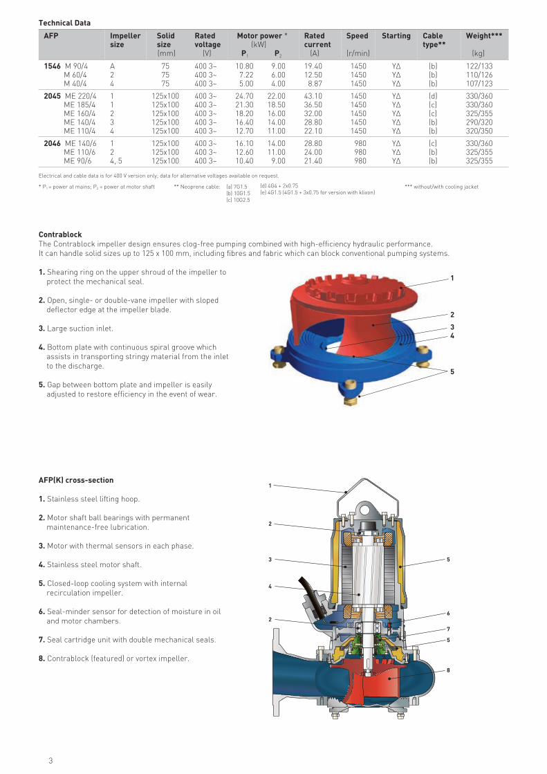
ContrablockThe Contrablock impeller design ensures clog-free pumping combined with high-efficiency hydraulic performance.It can handle solid sizes up to 125 x 100 mm, including fibres and fabric which can block conventional pumping systems.
1. Shearing ring on the upper shroud of the impeller to protect the mechanical seal.
2. Open, single- or double-vane impeller with sloped deflector edge at the impeller blade.
3. Large suction inlet.
4. Bottom plate with continuous spiral groove which assists in transporting stringy material from the inlet to the discharge.
5. Gap between bottom plate and impeller is easily adjusted to restore efficiency in the event of wear.
1
3
2
4
5
AFP(K) cross-section
1. Stainless steel lifting hoop.
2. Motor shaft ball bearings with permanent maintenance-free lubrication.
3. Motor with thermal sensors in each phase.
4. Stainless steel motor shaft.
5. Closed-loop cooling system with internal recirculation impeller.
6. Seal-minder sensor for detection of moisture in oil and motor chambers.
7. Seal cartridge unit with double mechanical seals.
8. Contrablock (featured) or vortex impeller.
1
3
2
2
4
5
6
7
8
5
Electrical and cable data is for 400 V version only; data for alternative voltages available on request.
Technical Data
3
0 0
0
0
4
8
1 2
00
0
0
30
2
4
20105 15 25
2
1
3
5
7
9
6
8
10
11
12
13
20 40 60 80 100 120
1
3
0 3020105 15 25 35
0 20 40 60 80 100 120
0
2
0
2
6
8
4
10
12
16
18
22
24
14
20
26
28
30
4
6
8
0
P [kW]2
Q
P [kW]2
Q
H [m]
P [kW]2
Q[l/s]
[m3/h]
[l/s]
[m3/h]
[l/s]
[m3/h]
[l/s]
[m3/h]
H [m]
P [kW]2
Q
H [m]
20
5 10 15 20
20 40 60 80
25
40 60 80 100 120
0
4
8
12
0 10 20 30
AFP 0834
AFP 0831
DN 80 DN 80
DN 80 DN 80
AFP 0832
AFP 083534
5
6
7
2
3
4
11
M30/4
2
M22/4 & S22/4*M15/4 & S22/4*M15/4
M15/4
M15/4
M15/4
H [m]
52
44
88
1212
1616
2020
2424
28
2832
3236
3640
40 44
44 48
48
2
3
4
5
6
1
M110/2M110/2
M110/2
M110/2
M70/2
M55/2
M70/2
M70/2
M70/2
M40/2
1
2
3
4
M110/2
M110/2
M110/2
M110/2
5 15 25
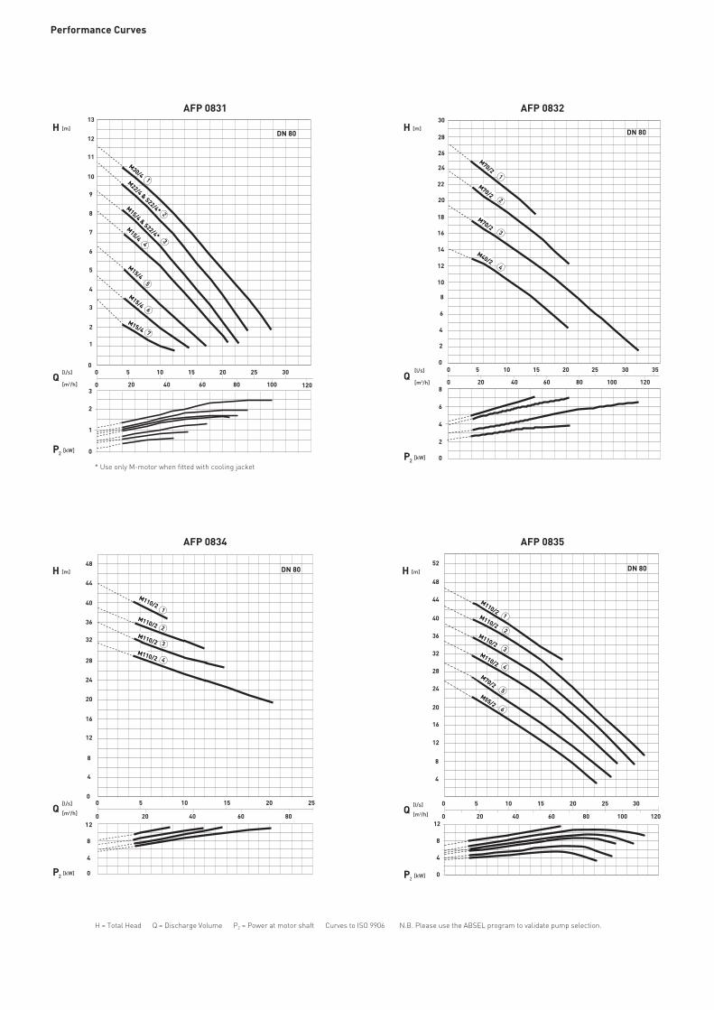
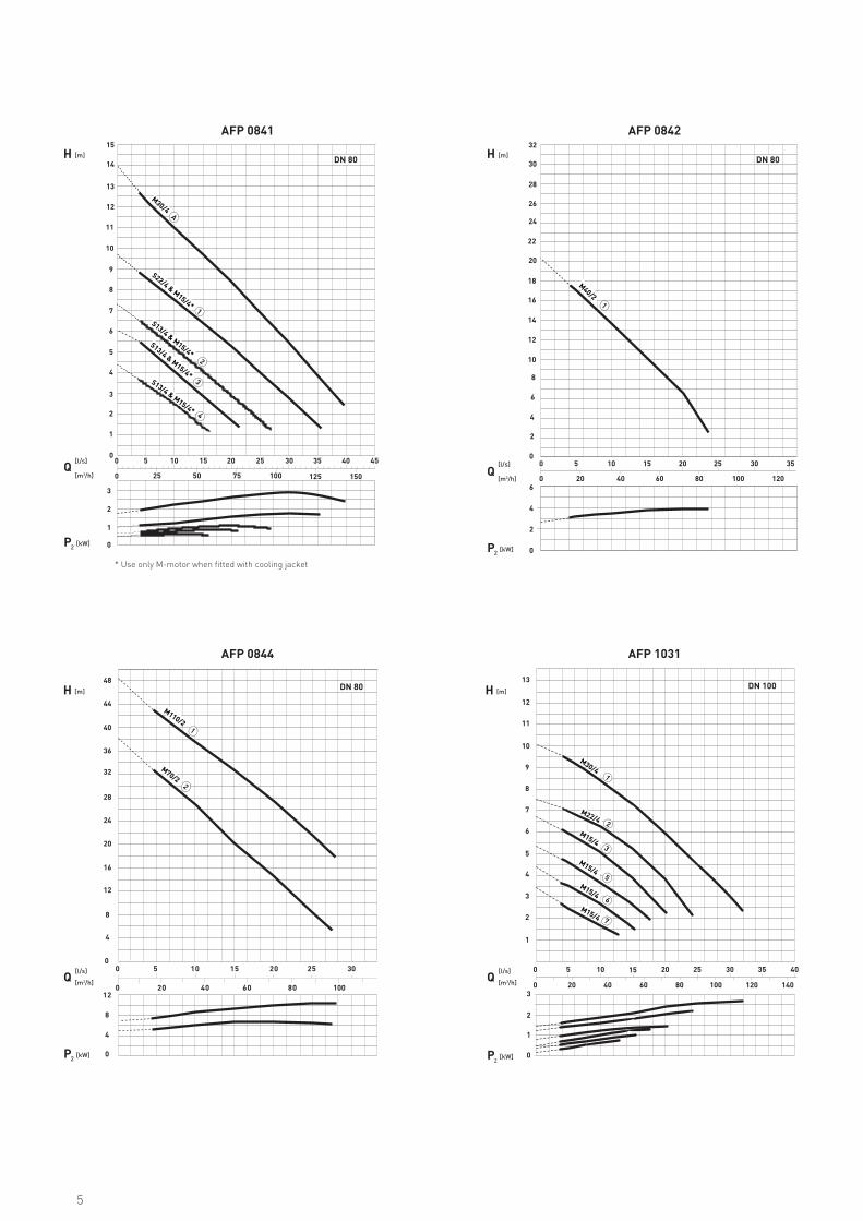
Performance Curves
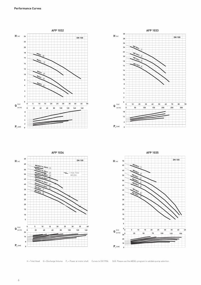
H = Total Head Q = Discharge Volume P2 = Power at motor shaft Curves to ISO 9906 N.B. Please use the ABSEL program to validate pump selection.
* Use only M-motor when fitted with cooling jacket
0 0
0
2 5
4
0
2 0 1 5 1 0 5 5
8 0 6 0 4 0 2 0
8
1 2
00
0
0
30 35 40 45
2
4
20105 15 25
2
1
3
5
7
9
6
8
10
11
12
13
14
15
25 50 75 100 125 150
1
3
0
P [kW]2
Q
P [kW]2
Q
H [m]
P [kW]2
Q[l/s]
[m3/h]
[l/s]
[m3/h]
[l/s]
[m3/h]
[l/s]
[m3/h]
H [m]
P [kW]2
Q
H [m]
20 40 60 80 100 120 140
0
0 10 20 30 40
AFP 0844
AFP 0841
DN 80
DN 80 DN 100
AFP 0842
AFP 1031
H [m]
13
14
30 15 25 35
100
28
3
1
2
3
12
164
520
624
7
288
329
3610
40 11
44 12
48
1
2
3
5
M30/4
M22/4
M15/4
M15/4
6
M15/4
7
M15/4
1
2
M110/2
M70/2
M30/4
1
A
S22/4 & M15/4*
2
S13/4 & M15/4*S13/4 & M15/4*S13/4 & M15/4*
3
4
0 3020105 15 25 35
0 20 40 60 80 100 120
0
0
2
6
8
4
10
12
16
18
22
24
14
20
26
28
30
32
2
4
6
DN 80
1
M40/2
* Use only M-motor when fitted with cooling jacket
5
00
0
0
30 35 40 4520105 15 25
5
25 50 75 100 125 150
1
2
3
4
5
7
6
5
0 20 40 60 80 100 120 140
0
0 10
10
10
20
20
20
30
30
30
40
40
45
50
55
60
65
70DN 100 DN 100
5
15
15
25
25
35
35
8
24
16
10
15
20
25
30
35
40
45
50
55
60
65
ME200/2 & 250/2ME200/2 & 250/2ME200/2 & 250/2ME200/2 & 250/2ME200/2 & 250/2ME200/2 & 250/2ME185/2
ME150/2
0 302010 9070 8040 50 60
0 50 100 150 200 250 300
0
2
6
8
4
10
12
16
18
22
24
14
20
26
28
30
P [kW]2
Q
P [kW]2
Q
H [m]
P [kW]2
Q[l/s]
[m3/h]
[l/s]
[m3/h]
[l/s]
[m3/h]
[l/s]
[m3/h]
H [m]
P [kW]2
Q
H [m]
AFP 1034
AFP 1032
DN 100
AFP 1033
AFP 1035
2
3
4
1
H [m]
ME185/4
ME160/4ME160/4
ME110/4
0 0
0
2 5 30 2 0 1 5 1 0 5
DN 100
2
4
6
8
0
2
4
6
8
10
12
14
35 40 45 50
20 40 60 80 100 120 140 160
16
18
20
22
24
A
1
2
3
M90/4
M60/4
M40/4
M40/4
4M40/4
0
6
12
18
x
xxx
x
x
x
1
2
3
4
5
67
8
ME250/2
ME250/2ME250/2ME250/2ME200/2
ME150/2ME150/2
Performance Curves
H = Total Head Q = Discharge Volume P2 = Power at motor shaft Curves to ISO 9906 N.B. Please use the ABSEL program to validate pump selection.
= max. flow ME200
6
0
0
1
2
3
5
6
7
8
9
10
11
12
13
4
14
15
1
2
3
DN 100
2
0
0
5
10
15
25
30
35
40
20
45
50
8
16
24
DN 100
1
2
2B3
A
ME220/4ME185/4
ME160/4ME140/4 & ME160/4
ME110/4
00
0
0
30 35 40 45
8
20105 15 25
8
4
25 50 75 100 125 150
4
1
M70/2
0 302010 9070 8040 50 60
0 50 100 150 200 250 300
0
2
6
8
4
10
12
16
18
22
24
14
20
26
28
30
DN 100
1
2
3
A
M90/4
M60/4M60/4
M40/4
3
0
6
9
P [kW]2
Q
P [kW]2
Q
H [m]
P [kW]2
Q[l/s]
[m3/h]
[l/s]
[m3/h]
[l/s]
[m3/h][l/s]
[m3/h]
H [m]
P [kW]2
Q
H [m]
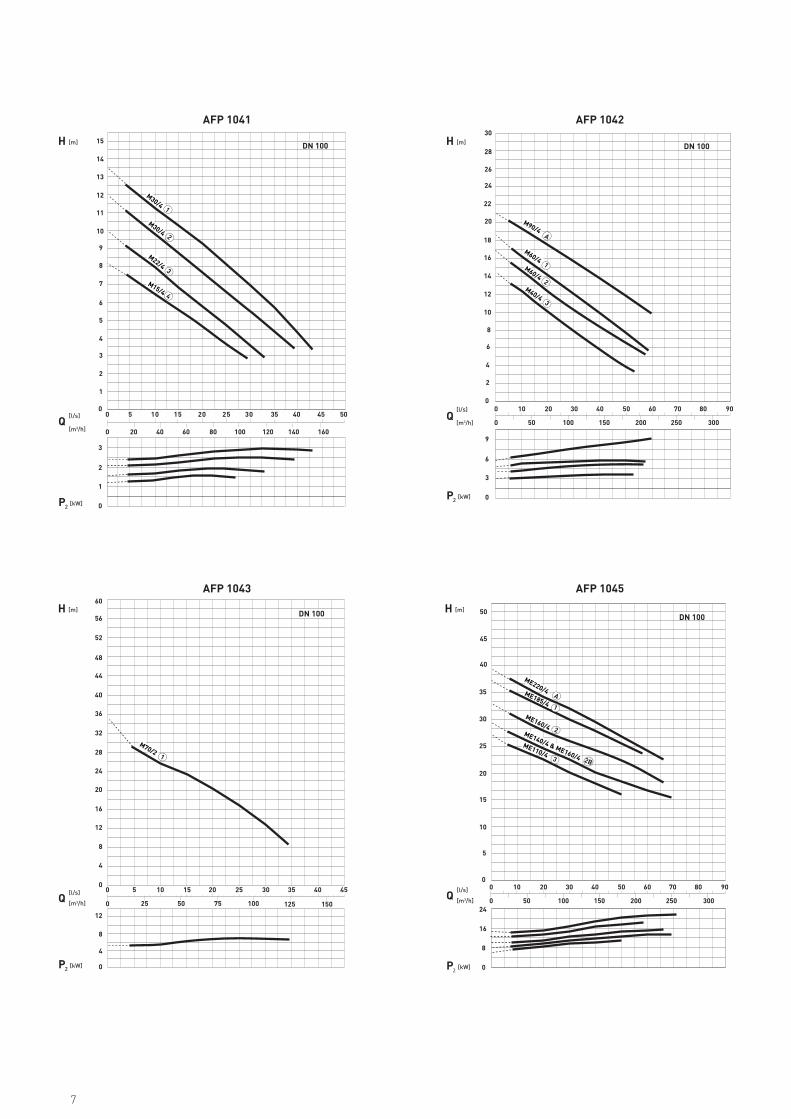
AFP 1043
AFP 1041
DN 100
AFP 1042
AFP 1045
H [m]
12
12
16
20
24
28
32
36
40
44
48
52
56
60
0 302010 9070 8040 50 60
0 50 100 150 200 250 300
0
0
2 5 30 2 0 1 5 1 0 5
35 40 45 50
20 40 60 80 100 120 140 160
M30/41
M15/4 4
M22/43
M30/4
7
1000 302010 9070 8040 50 60
0 50 100 150 200 250 300 350
0
2
6
8
4
10
18
12
12
16
18
22
24
14
20
26
28
30
DN 150
2
3
4
1
ME185/4ME160/4ME140/4
ME110/4
6
0
0
0
5
10
15
25
30
35
40
45
50
55
60
65
20
70
75
8
16
24
DN 100
P [kW]2
Q
H [m]
P [kW]2
Q[l/s]
[m3/h]
[l/s]
[m3/h]
H [m]
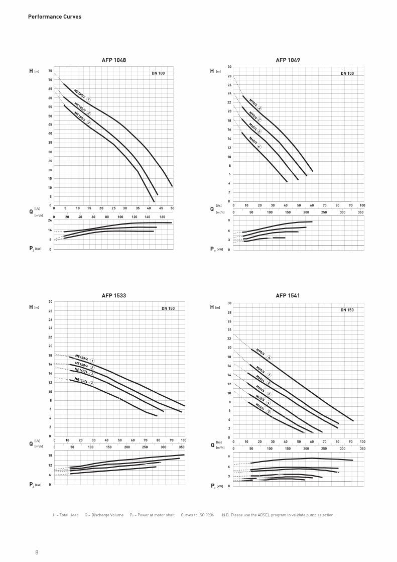
AFP 1533
AFP 1048
0
0
2 5 30 2 0 1 5 1 0 5
35 40 45 50
20 40 60 80 100 120 140 160
ME250/2
ME185/2ME150/2
1
2
3
0 302010 90 10070 8040 50 60
0 50 100 150 200 250 300 350
0
2
6
8
4
10
12
16
18
22
24
14
20
26
28
30
DN 150
1
2
3
4
5
A
M90/4
M60/4M60/4
3
6
9
0P [kW]2
Q
[l/s]
[m3/h]
[l/s]
[m3/h]
P [kW]2
Q
H [m]
AFP 1049
AFP 1541
H [m]
0 302010 90 10070 8040 50 60
0 50 100 150 200 250 300 350
0
2
6
8
4
10
12
16
18
22
24
14
20
26
28
30
DN 100
2
3
4A
M90/4
M90/4
M60/4
M40/4
3
0
6
9
M40/4
M40/4M40/4
Performance Curves
H = Total Head Q = Discharge Volume P2 = Power at motor shaft Curves to ISO 9906 N.B. Please use the ABSEL program to validate pump selection.
8
0 0
0
0
8
20 40 60 80 100
100 200 300 400 500 600 700
120 140 160 180 200 220
DN 150
4
8
20
24
12
28
32
16
16
24
36
40
44
48
52
A
1
2
3
ME220/4ME185/4 ME160/4 ME140/4
ME110/4
0 0
0
0
8
4
P [kW]2
Q
H [m]
[l/s]
[m3/h]
20 40 60 80 100
100 200 300 400 500 600 700
120 140 160 180 200 220
DN 150
2
4
6
8
10
12
14
16
12
18
20
22
24
26
A2
4
M90/4
M60/4
M40/4
0 0
0
0
8
P [kW]2
Q
H [m]
P [kW]2
Q[l/s]
[m3/h]
[l/s]
[m3/h]
H [m]
20 40 60 80 100
100 200 300 400 500 600 700
120 140 160 180 200 220
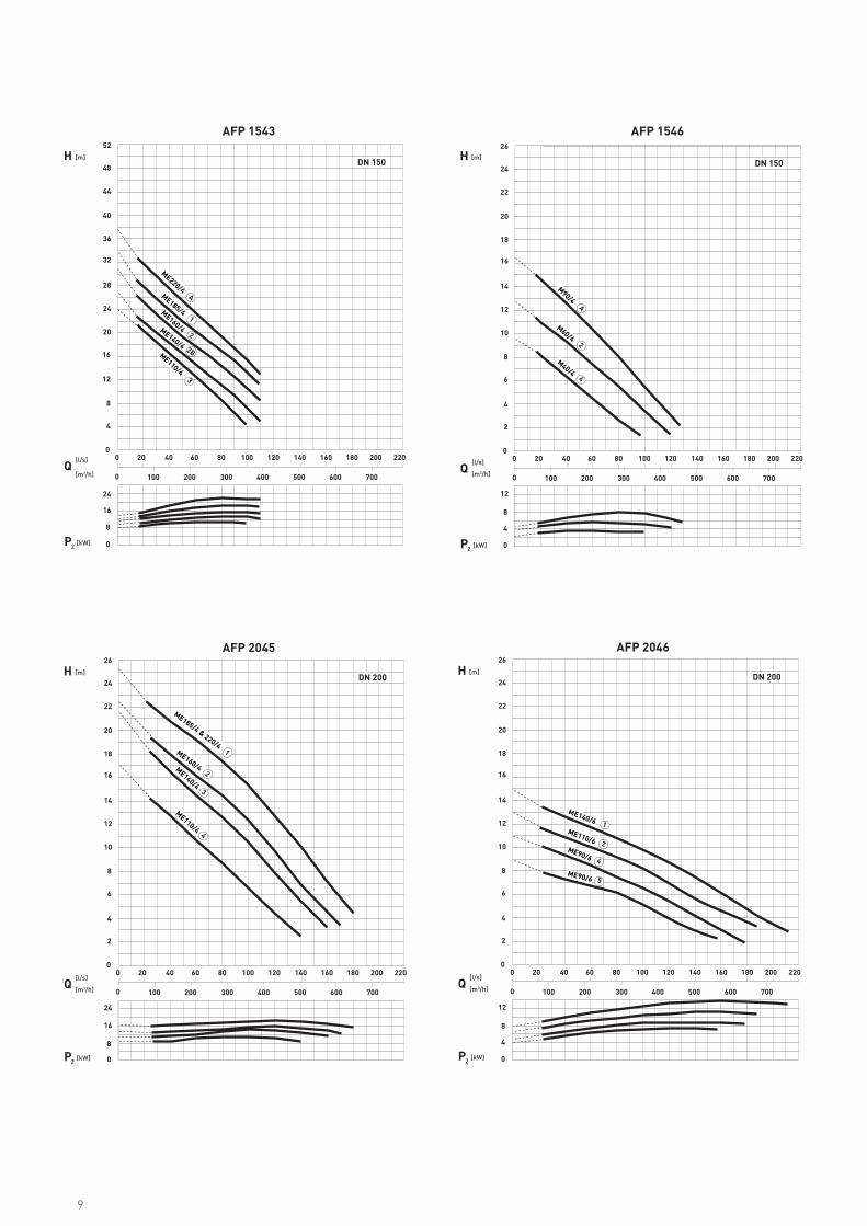
AFP 2045
AFP 1543
DN 200
AFP 1546
2
4
6
8
10
12
14
16
16
24
18
20
22
24
26
1
2
3
4
ME185/4 & 220/4ME160/4 ME140/4
ME110/4
0 0
0
0
8
4
P [kW]2
Q
H [m]
[l/s]
[m3/h]
20 40 60 80 100
100 200 300 400 500 600 700
120 140 160 180 200 220
AFP 2046
DN 200
2
4
6
8
10
12
14
16
12
18
20
22
24
26
1
2
4
5
ME140/6ME110/6ME90/6
ME90/6
2B
9
14*
DN 1
A
C
UT
DN 1
øW
E
F
85
90
52 4070
B
2“
GHD
ba
+ —
XEB18 **
c d
DN 1
DN 2
K
J
M
P
G2N
Q
XE
K
J
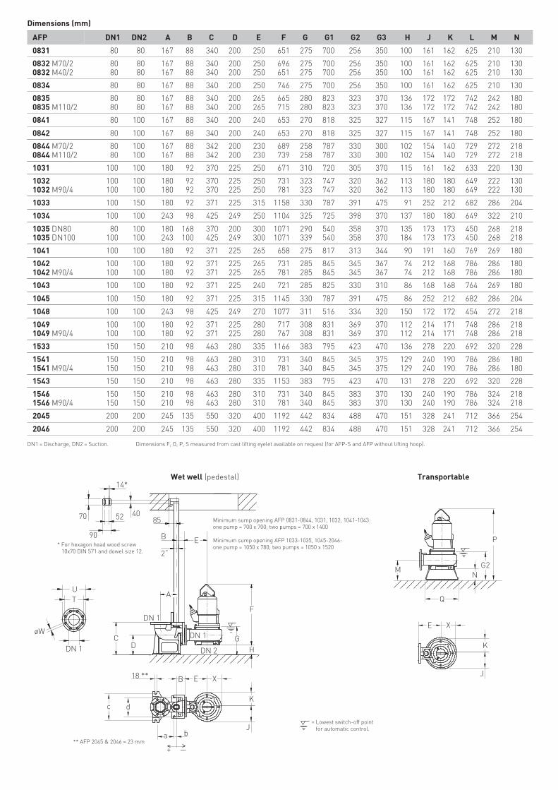
AFP DN1 DN2 A B C D E F G G1 G2 G3 H J K L M N
0831 80 80 167 88 340 200 250 651 275 700 256 350 100 161 162 625 210 130
0832 M70/20832 M40/2
80 80 167 88 340 200 250 696 275 700 256 350 100 161 162 625 210 130 80 80 167 88 340 200 250 651 275 700 256 350 100 161 162 625 210 130
0834 80 80 167 88 340 200 250 746 275 700 256 350 100 161 162 625 210 130
08350835 M110/2
80 80 167 88 340 200 265 665 280 823 323 370 136 172 172 742 242 180 80 80 167 88 340 200 265 715 280 823 323 370 136 172 172 742 242 180
0841 80 100 167 88 340 200 240 653 270 818 325 327 115 167 141 748 252 180
0842 80 100 167 88 340 200 240 653 270 818 325 327 115 167 141 748 252 180
0844 M70/20844 M110/2
80 100 167 88 342 200 230 689 258 787 330 300 102 154 140 729 272 218 80 100 167 88 342 200 230 739 258 787 330 300 102 154 140 729 272 218
1031 100 100 180 92 370 225 250 671 310 720 305 370 115 161 162 633 220 130
10321032 M90/4
100 100 180 92 370 225 250 731 323 747 320 362 113 180 180 649 222 130 100 100 180 92 370 225 250 781 323 747 320 362 113 180 180 649 222 130
1033 100 150 180 92 371 225 315 1158 330 787 391 475 91 252 212 682 286 204
1034 100 100 243 98 425 249 250 1104 325 725 398 370 137 180 180 649 322 210
1035 DN801035 DN100
80 100 180 168 370 200 300 1071 290 540 358 370 135 173 173 450 268 218 100 100 243 100 425 249 300 1071 339 540 358 370 184 173 173 450 268 218
1041 100 100 180 92 371 225 265 658 275 817 313 344 90 191 160 769 269 180
10421042 M90/4
100 100 180 92 371 225 265 731 285 845 345 367 74 212 168 786 286 180 100 100 180 92 371 225 265 781 285 845 345 367 74 212 168 786 286 180
1043 100 100 180 92 371 225 240 721 285 825 330 310 86 168 168 764 269 180
1045 100 150 180 92 371 225 315 1145 330 787 391 475 86 252 212 682 286 204
1048 100 100 243 98 425 249 270 1077 311 516 334 320 150 172 172 454 272 218
10491049 M90/4
100 100 180 92 371 225 280 717 308 831 369 370 112 214 171 748 286 218 100 100 180 92 371 225 280 767 308 831 369 370 112 214 171 748 286 218
1533 150 150 210 98 463 280 335 1166 383 795 423 470 136 278 220 692 320 228
15411541 M90/4
150 150 210 98 463 280 310 731 340 845 345 375 129 240 190 786 286 180 150 150 210 98 463 280 310 781 340 845 345 375 129 240 190 786 286 180
1543 150 150 210 98 463 280 335 1153 383 795 423 470 131 278 220 692 320 228
15461546 M90/4
150 150 210 98 463 280 310 731 340 845 383 370 130 240 190 786 324 218 150 150 210 98 463 280 310 781 340 845 383 370 130 240 190 786 324 218
2045 200 200 245 135 550 320 400 1192 442 834 488 470 151 328 241 712 366 254
2046 200 200 245 135 550 320 400 1192 442 834 488 470 151 328 241 712 366 254
Wet well (pedestal) Transportable
= Lowest switch-off point for automatic control.
* For hexagon head wood screw 10x70 DIN 571 and dowel size 12.
** AFP 2045 & 2046 = 23 mm
DN1 = Discharge, DN2 = Suction. Dimensions F, O, P, S measured from cast lifting eyelet available on request (for AFP-S and AFP without lifting hoop).
Minimum sump opening AFP 0831-0844, 1031, 1032, 1041-1043:one pump = 700 x 700; two pumps = 700 x 1400
Minimum sump opening AFP 1033-1035, 1045-2046:one pump = 1050 x 780; two pumps = 1050 x 1520
Dimensions (mm)
E
G3Z
j
e(1 (2
f
18
g
h
O
L RG1
S
K
J
XE
SY
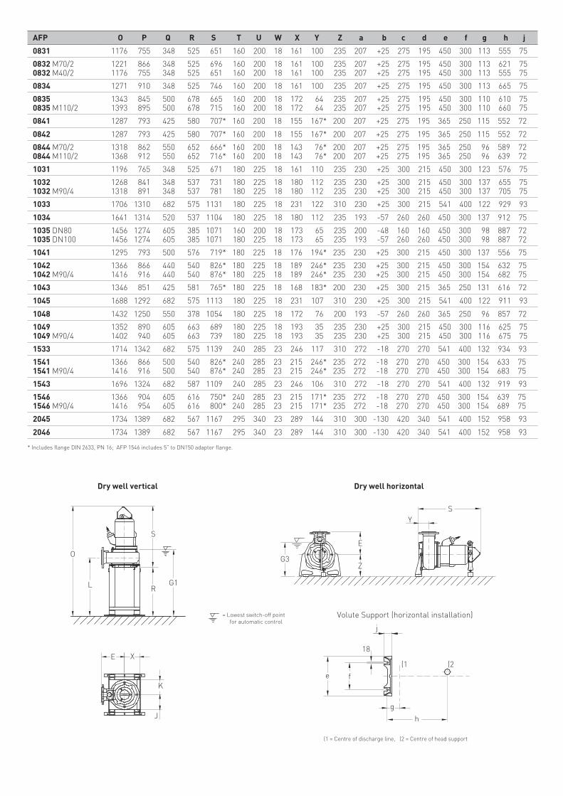
AFP O P Q R S T U W X Y Z a b c d e f g h j
0831 1176 755 348 525 651 160 200 18 161 100 235 207 +25 275 195 450 300 113 555 75
0832 M70/20832 M40/2
1221 866 348 525 696 160 200 18 161 100 235 207 +25 275 195 450 300 113 621 75 1176 755 348 525 651 160 200 18 161 100 235 207 +25 275 195 450 300 113 555 75
0834 1271 910 348 525 746 160 200 18 161 100 235 207 +25 275 195 450 300 113 665 75
08350835 M110/2
1343 845 500 678 665 160 200 18 172 64 235 207 +25 275 195 450 300 110 610 75 1393 895 500 678 715 160 200 18 172 64 235 207 +25 275 195 450 300 110 660 75
0841 1287 793 425 580 707* 160 200 18 155 167* 200 207 +25 275 195 365 250 115 552 72
0842 1287 793 425 580 707* 160 200 18 155 167* 200 207 +25 275 195 365 250 115 552 72
0844 M70/20844 M110/2
1318 862 550 652 666* 160 200 18 143 76* 200 207 +25 275 195 365 250 96 589 72 1368 912 550 652 716* 160 200 18 143 76* 200 207 +25 275 195 365 250 96 639 72
1031 1196 765 348 525 671 180 225 18 161 110 235 230 +25 300 215 450 300 123 576 75
10321032 M90/4
1268 841 348 537 731 180 225 18 180 112 235 230 +25 300 215 450 300 137 655 75 1318 891 348 537 781 180 225 18 180 112 235 230 +25 300 215 450 300 137 705 75
1033 1706 1310 682 575 1131 180 225 18 231 122 310 230 +25 300 215 541 400 122 929 93
1034 1641 1314 520 537 1104 180 225 18 180 112 235 193 -57 260 260 450 300 137 912 75
1035 DN801035 DN100
1456 1274 605 385 1071 160 200 18 173 65 235 200 -48 160 160 450 300 98 887 72 1456 1274 605 385 1071 180 225 18 173 65 235 193 -57 260 260 450 300 98 887 72
1041 1295 793 500 576 719* 180 225 18 176 194* 235 230 +25 300 215 450 300 137 556 75
10421042 M90/4
1366 866 440 540 826* 180 225 18 189 246* 235 230 +25 300 215 450 300 154 632 75 1416 916 440 540 876* 180 225 18 189 246* 235 230 +25 300 215 450 300 154 682 75
1043 1346 851 425 581 765* 180 225 18 168 183* 200 230 +25 300 215 365 250 131 616 72
1045 1688 1292 682 575 1113 180 225 18 231 107 310 230 +25 300 215 541 400 122 911 93
1048 1432 1250 550 378 1054 180 225 18 172 76 200 193 -57 260 260 365 250 96 857 72
10491049 M90/4
1352 890 605 663 689 180 225 18 193 35 235 230 +25 300 215 450 300 116 625 75 1402 940 605 663 739 180 225 18 193 35 235 230 +25 300 215 450 300 116 675 75
1533 1714 1342 682 575 1139 240 285 23 246 117 310 272 -18 270 270 541 400 132 934 93
15411541 M90/4
1366 866 500 540 826* 240 285 23 215 246* 235 272 -18 270 270 450 300 154 633 75 1416 916 500 540 876* 240 285 23 215 246* 235 272 -18 270 270 450 300 154 683 75
1543 1696 1324 682 587 1109 240 285 23 246 106 310 272 -18 270 270 541 400 132 919 93
15461546 M90/4
1366 904 605 616 750* 240 285 23 215 171* 235 272 -18 270 270 450 300 154 639 75 1416 954 605 616 800* 240 285 23 215 171* 235 272 -18 270 270 450 300 154 689 75
2045 1734 1389 682 567 1167 295 340 23 289 144 310 300 -130 420 340 541 400 152 958 93
2046 1734 1389 682 567 1167 295 340 23 289 144 310 300 -130 420 340 541 400 152 958 93
Dry well vertical Dry well horizontal
(1 = Centre of discharge line, (2 = Centre of head support
Volute Support (horizontal installation)= Lowest switch-off point for automatic control
* Includes flange DIN 2633, PN 16; AFP 1546 includes 5” to DN150 adaptor flange.
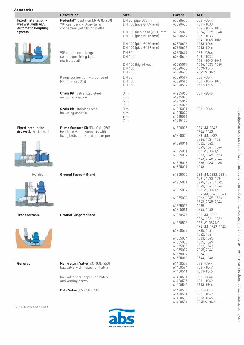
Accessories
Description Size Part no. AFPFixed installation - wet well with ABSAutomatic Coupling System
Pedestal* (cast iron EN-GJL-250)90º cast bend - plug/clampconnection (with fixing bolts)
DN 80 (pipe Ø90 mm)DN 100 (pipe Ø109 mm)
DN 100 high head (Ø109 mm)DN 100 (pipe Ø115 mm)
DN 150 (pipe Ø160 mm)DN 150 (pipe Ø169 mm)
6232065062320653
6232502062320654
6232065662320657
0831-08441031-1033,1041-1045, 10491034, 1035, 10481031-1033,1041-1045, 10491533-15461533-1546
90º cast bend - flangeconnection (fixing boltsnot included)
DN 80DN 100
DN 100 (high-head)DN 150DN 200
6232064962320652
623250196232065562320658
0831-08441031-1033,1041-1045, 10491034, 1035, 10481533-15462045 & 2046
flange connection without bend(with fixing bolts)
DN 80DN 100DN 150
623205176232051662320537
0831-08441031-1045, 10491533-1546
Chain Kit (galvanized steel)including shackle
3 m4 m6 m7 m
61265065612650936126506961265096
0831-2046
Chain Kit (stainless steel)including shackle
3 m4 m6 m7 m
61265081612650996126508561265102
0831-2046
Fixed installation - dry well, (horizontal)
Pump Support Kit (EN-GJL-250)head and volute supports withfixing bolts and vibration damper
61820025
61820040
61820041
6182500161825007
6182500861825009
0841/M, 0842,0844, 10430831/M, 0832,0834, 1031, 10411032, 1042,1049, 1541, 15460831/S, 0841/S1033, 1045, 15331543, 2045, 20460835, 1034, 10351048
(vertical) Ground Support Stand 61355000
61355001
61355002
61355003
6135500861355011
0831/M, 0832, 0834,1031, 1032, 10340835, 1041, 1042,1049, 1541, 15460831/S, 0841/S,0841/M, 0842, 10431033, 1045, 1533,1543, 2045, 204610350844, 1048
Transportable Ground Support Stand 61350525
61350526
61350527
613550046135500561355006613550076135500961355010
0831/M, 0832,0834, 1031, 10320831/S, 0841/S,0841/M, 0842, 10430835, 1041,1042, 15411033, 10451035, 10491533, 15432045, 204610340844, 1048
General Non-return Valve (EN-GJL-250)ball valve with inspection hatch
614005236140052461400541
0831-08441031-10491533-1546
ball valve with inspection hatchand venting screw
614005346140053561400542
0831-08441031-10491533-1546
Gate Valve (EN-GJL-250) 61420500614205016142050361420504
0831-08441031-10491533-15462045 & 2046
* 2-inch guide rail not included
ABS
subm
ersi
ble
sew
age
pum
p AF
P 0
831-
2046
G
B 2
009-
08-1
0 | W
e re
serv
e th
e ri
ghts
to a
lter
spe
cific
atio
ns d
ue to
tech
nica
l dev
elop
men
ts.
Recommended