The most advanced drainage system of its kind
ACO Qmax® Technical Data
UniclassL7315 + L2123
EPICJ3413
CI/SfB(52.5) In6
Contents
Load Classes 3
ACO Qmax® 600 System
Pedestrian and Car Park applications 4
Highway, Distribution Centre and Airport Pavement applications 5
Accessories 6
ACO Qmax® 900 System
Pedestrian and Car Park applications 7
Highway, Distribution Centre and Airport Pavement applications 8
Accessories 9
ACO Qmax® Flow Regulators 10
Geometry and Properties Data 11
2
ACO Qmax® System
TECHNICAL DATA
ACO Qmax® System

Load Classes
ACO Qmax® is suitable for use in all load classapplications. The patented beam feature enables use ofthe optimum pavement reinforcement details whendealing with specialist and high load situations, therebyreducing total cost and ensuring speed of installation isnot compromised. Additional reinforcement may bespecified in the concrete surround for higher loadapplications.
ACO Qmax® is suitable for the following applications:
The ACO Qmax® channel system is protected by patent and registered design rights. All intellectual rights are the property of ACO Technologies plc.
3
ACO Qmax® System
TECHNICAL DATA
Group1 Group 2 Group 3 Group4 Group 5 Group 6
BS EN 1433:2002 Load Class
Load Class A15kN
Pedestrian
Load Class B125kN
Private car parks
Load Class C250kN
Public car/van parks
Load Class D400kN
Highways
Load Class E600kN
Distribution centres
Load Class F900kN
Airport pavements
All products shown in the technical data charts are supplied without water seals. For details of components supplied withwater seals pre fitted, please contact the ACO Water Management sales office on 01462 816666.
i

4
ACO Qmax® 600 System
TECHNICAL DATA
DPedestrian and Car Park applications - 600 system:
Ovoid Channels
Each channel section, manufactured from tough and corrosion resistant MDPE is supplied complete with:
� Discrete galvanised steel heel safe (10mm slot width) continuous waterway inlet slot
� Nominal waterway inlet area: 10000mm2/m
� Channel assembly and connection fixings
Ovoid Channel complete with Side Inlets
Order No
401013
Dimensions (mm)Ovoid sectionW x H
400 x 600
Nominallength(mm)
1000
Slotwidth(mm)
10
Overallheight(mm)
940
Nominal waterway intake area (mm2)
10,000
Weight (kg)
23
Finished road level to Invert of nominal bore pipe connectionØ150mm Ø225mm Ø300mm
635 673 710
Order No
401002
Dimensions (mm)Ovoid sectionW x H
400 x 600
Nominal length(mm)
2000
Slot width (mm)
10
Overall height(mm)
940
Nominal waterway intake area (mm2)
20,000
Weight (kg)
38
Notes1. 1-metre channels supplied with symmetrical horizontal inlet spigots for easy pipe connections in vitrified clay, concrete or plastic.2. 150mm, 225mm and 300mm nominal bore inlet pipes accommodated.3. Side inlet spigots are supplied blank and easily opened with a handsaw or disc cutter. Connection to pipes achieved by selecting appropriate
flexible couplings supplied by others.4. For reference, actual pipe connection spigot outside diameters: 200mm and 380mm.
642m
m
2000mm 400mm
600m
m
940m
m
22
880m
mIn
vert
880m
mIn
vert
1000mm400mm
940m
m
600m
mØ38
0mm
Ø20
0mm
3 642m
m
A B C

5
ACO Qmax® 600 System
TECHNICAL DATA
Highway, Distribution Centre and Airport Pavement applications - 600 system:
Ovoid Channels
Each channel section, manufactured from tough and corrosion resistant MDPE is supplied complete with:
� Heavy duty hot dipped galvanised steel edge continuous waterway inlet slot protection frame 40mm x 40mm x 4mm
� Nominal waterway inlet area: 30,000mm2/m
� Heavy-duty concrete anchors 150mm long, 500mm centres
� Channel assembly and connection fixings
Ovoid Channel complete with Side Inlets
Order No
401011
Dimensions (mm)Ovoid sectionW x H
400 x 600
Nominallength(mm)
1000
Slotwidth(mm)
30
Overallheight(mm)
940
Nominal waterway intake area (mm2)
30,000
Weight (kg)
23
Finished road level to Invert of nominal bore pipe connectionØ150mm Ø225mm Ø300mm
635 673 710
Order No
401000
Dimensions (mm)Ovoid sectionW x H
400 x 600
Nominal length(mm)
2000
Slot width (mm)
30
Overall height(mm)
940
Nominal waterway intake area (mm2)
60,000
Weight (kg)
38
Notes1. 1-metre channels supplied with symmetrical horizontal inlet spigots for easy pipe connections in vitrified clay, concrete or plastic.2. 150mm, 225mm and 300mm nominal bore inlet pipes accommodated.3. Side inlet spigots are supplied blank and easily opened with a handsaw or disc cutter. Connection to pipes achieved by selecting appropriate
flexible couplings supplied by others.4. For reference, actual pipe connection spigot outside diameters: 200mm and 380mm.
642m
m2000mm 400mm
600m
m
940m
m
880m
mIn
vert
880m
mIn
vert
1000mm 400mm
940m
m
600m
mØ38
0mm
Ø20
0mm
642m
m
D E F
6
ACO Qmax® 600 System
TECHNICAL DATA
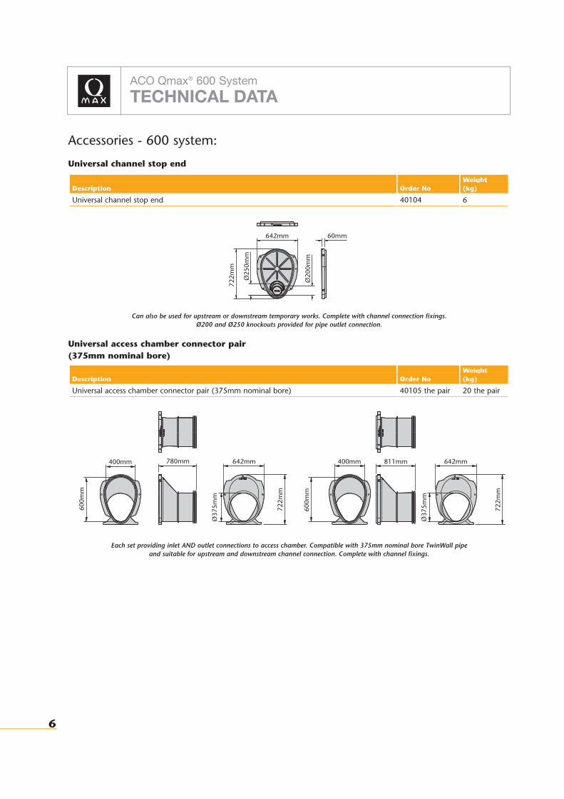
Accessories - 600 system:
Universal channel stop end
Can also be used for upstream or downstream temporary works. Complete with channel connection fixings.Ø200 and Ø250 knockouts provided for pipe outlet connection.
Universal access chamber connector pair (375mm nominal bore)
Each set providing inlet AND outlet connections to access chamber. Compatible with 375mm nominal bore TwinWall pipe and suitable for upstream and downstream channel connection. Complete with channel fixings.
Description
Universal access chamber connector pair (375mm nominal bore)
Order No
40105 the pair
Weight (kg)
20 the pair
Description
Universal channel stop end
Order No
40104
Weight (kg)
6
400mm 780mm 642mm
600m
m
722m
m
Ø37
5mm
400mm 811mm 642mm
600m
m
Ø37
5mm
722m
m
642mm 60mm72
2mm
Ø25
0mm
Ø20
0mm
7
ACO Qmax® 900 System
TECHNICAL DATA
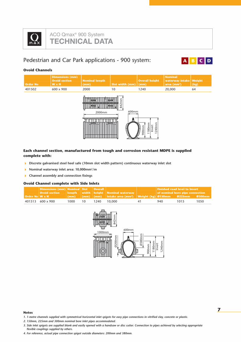
Pedestrian and Car Park applications - 900 system:
Ovoid Channels
Each channel section, manufactured from tough and corrosion resistant MDPE is supplied complete with:
� Discrete galvanised steel heel safe (10mm slot width pattern) continuous waterway inlet slot
� Nominal waterway inlet area: 10,000mm2/m
� Channel assembly and connection fixings
Ovoid Channel complete with Side Inlets
Order No
401513
Dimensions (mm)Ovoid sectionW x H
600 x 900
Nominallength(mm)
1000
Slotwidth(mm)
10
Overallheight(mm)
1240
Nominal waterway intake area (mm2)
10,000
Weight (kg)
41
Finished road level to Invert of nominal bore pipe connectionØ150mm Ø225mm Ø300mm
940 1015 1050
Order No
401502
Dimensions (mm)Ovoid sectionW x H
600 x 900
Nominal length(mm)
2000
Slot width (mm)
10
Overall height(mm)
1240
Nominal waterway intake area (mm2)
20,000
Weight (kg)
64
Notes1. 1-metre channels supplied with symmetrical horizontal inlet spigots for easy pipe connections in vitrified clay, concrete or plastic.2. 150mm, 225mm and 300mm nominal bore inlet pipes accommodated.3. Side inlet spigots are supplied blank and easily opened with a handsaw or disc cutter. Connection to pipes achieved by selecting appropriate
flexible couplings supplied by others.4. For reference, actual pipe connection spigot outside diameters: 200mm and 380mm.
842m
m
2000mm 600mm
900m
m
1240
mm
22
1180
mm
Inve
rt11
80m
mIn
vert
1000mm600mm
1240
mm
900m
mØ38
0mm
Ø20
0mm
3
3
842m
m
DA B C
8
ACO Qmax® 900 System
TECHNICAL DATA
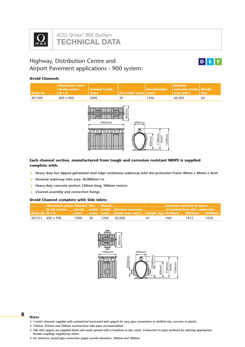
Highway, Distribution Centre and Airport Pavement applications - 900 system:
Ovoid Channels
Each channel section, manufactured from tough and corrosion resistant MDPE is supplied complete with:
� Heavy duty hot dipped galvanised steel edge continuous waterway inlet slot protection frame 40mm x 40mm x 4mm
� Nominal waterway inlet area: 30,000mm2/m
� Heavy-duty concrete anchors 150mm long, 500mm centres
� Channel assembly and connection fixings
Ovoid Channel complete with Side Inlets
Order No
401511
Dimensions (mm)Ovoid sectionW x H
600 x 900
Nominallength(mm)
1000
Slotwidth(mm)
30
Overallheight(mm)
1240
Nominal waterway intake area (mm2)
30,000
Weight (kg)
41
Finished road level to Invert of nominal bore pipe connectionØ150mm Ø225mm Ø300mm
940 1015 1050
Order No
401500
Dimensions (mm)Ovoid sectionW x H
600 x 900
Nominal length(mm)
2000
Slot width (mm)
30
Overall height(mm)
1240
Nominal waterway intake area (mm2)
60,000
Weight (kg)
64
Notes1. 1-metre channels supplied with symmetrical horizontal inlet spigots for easy pipe connections in vitrified clay, concrete or plastic.2. 150mm, 225mm and 300mm nominal bore inlet pipes accommodated.3. Side inlet spigots are supplied blank and easily opened with a handsaw or disc cutter. Connection to pipes achieved by selecting appropriate
flexible couplings supplied by others.4. For reference, actual pipe connection spigot outside diameters: 200mm and 380mm.
842m
m2000mm 400mm
900m
m
1240
mm
1180
mm
Inve
rt
1180
mm
Inve
rt
1000mm 400mm
1240
mm
900m
mØ38
0mm
Ø20
0mm
842m
m
D E F

9
ACO Qmax® 900 System
TECHNICAL DATA
Accessories - 900 system:
Universal channel stop end
Can also be used for upstream or downstream temporary works. Complete with channel connection fixings.Ø200, Ø250 and Ø300 knockouts provided for pipe outlet connection.
Universal access chamber connector pair (600mm nominal bore)
Each set providing inlet AND outlet connections to access chamber. Compatible with 600mm nominal bore TwinWall pipe and suitable for upstream and downstream channel connection. Complete with channel fixings.
Description
Universal access chamber connector pair (600mm nominal bore)
Order No
40155 the pair
Weight (kg)
37 the pair
Description
Universal channel stop end
Order No
40154
Weight (kg)
11
600mm 780mm 842mm
900m
m
1022
mm
591m
m
600mm 811mm 842mm
900m
m
591m
m
1022
mm
842mm 60mm
1022
mm
Ø30
0mm
Ø25
0mm
Ø20
0mm
10
ACO Qmax® System
TECHNICAL DATA
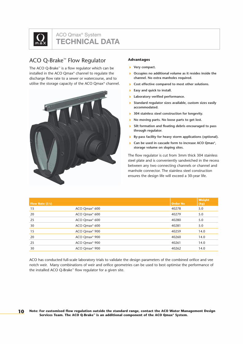
ACO Q-Brake™ Flow RegulatorThe ACO Q-Brake™ is a flow regulator which can beinstalled in the ACO Qmax® channel to regulate thedischarge flow rate to a sewer or watercourse, and toutilise the storage capacity of the ACO Qmax® channel.
Advantages
� Very compact.
� Occupies no additional volume as it resides inside thechannel. No extra manholes required.
� Cost effective compared to most other solutions.
� Easy and quick to install.
� Laboratory verified performance.
� Standard regulator sizes available, custom sizes easilyaccommodated.
� 304 stainless steel construction for longevity.
� No moving parts. No loose parts to get lost.
� Silt formation and floating debris encouraged to passthrough regulator.
� By-pass facility for heavy storm applications (optional).
� Can be used in cascade form to increase ACO Qmax®‚storage volume on sloping sites.
The flow regulator is cut from 3mm thick 304 stainlesssteel plate and is conveniently sandwiched in the recessbetween any two connecting channels or channel andmanhole connector. The stainless steel constructionensures the design life will exceed a 30-year life.
Flow Rate (l/s)
15 ACO Qmax® 600
20 ACO Qmax® 600
25 ACO Qmax® 600
30 ACO Qmax® 600
15 ACO Qmax® 900
20 ACO Qmax® 900
25 ACO Qmax® 900
30 ACO Qmax® 900
Order No
40278
40279
40280
40281
40259
40260
40261
40262
Weight (kg)
5.0
5.0
5.0
5.0
14.0
14.0
14.0
14.0
ACO has conducted full-scale laboratory trials to validate the design parameters of the combined orifice and veenotch weir. Many combinations of weir and orifice geometries can be used to best optimise the performance ofthe installed ACO Q-Brake™ flow regulator for a given site.
Note: For customised flow regulation outside the standard range, contact the ACO Water Management DesignServices Team. The ACO Q-Brake™ is an additional component of the ACO Qmax® System.

11
ACO Qmax® System
TECHNICAL DATA
1.0 ACO Qmax®: Geometry and Properties Data
1.1 ACO Qmax®: Geometry and Properties Data of the MDPE liner
* In an unpolluted environment the atmospheric zinc depletion rate per 100 metres of channel run (assuming 2 microns per year) is 0.23kg / year. With a mean galvanising thickness of 70 microns, a life in excess of 30 years may be expected.
† Airport pavement, distribution centre and highway applications unless otherwise stated
†† Car park applications
1.2 Geometry and Properties of Concreted Section
* Excluding working space and formwork
** Excluding blinding concrete
1.3 Typical Channel Arrangements
* Note that by accepting a greater outlet spacing at steeper slopes then the flow velocity will tend to exceed the critical velocity
† Airport pavement, distribution centre and highway applications
Order No
Length to Outlet (m)
Catchment Depth (m)
Longitudinal Slope (%)
Area Drained (ha)
ACO Qmax® 600
50 – 1000
5 – 100
0.0 – 1.0*
0.25 – 3.0
ACO Qmax® 900
50 – 1500
5 – 200
0.0 – 1.0*
0.25 – 5.0
Order No
Minimum Width (m)*
Minimum Depth (m)**
Invert Depth (m) incl. angle
Concrete per metre Length**
Reinforcement
ACO Qmax® 600
0.8
1.1 approx.
0.880
<0.7m3
see section 2.0
ACO Qmax® 900
1.0
1.4 approx.
1.180
<1.0m3
see section 2.0
Order No
Shape
Cross Sectional Area (m2)
Perimeter (m)
Hydraulic Radius (m)
Critical Velocity (m/s)
Material Thickness (mm)
Weight (kg) 2m channel unit assembly
1m channel unit assembly
Internal Dimensions Depth (m)
Maximum width (m)
External Dimensions Width o/a collar (m)
o/a height (m)
Inlet Slot Internal width (mm)
Corrosion protection life (years)
ACO Qmax® 600†
Ovoid
0.1838
1.585
0.116
2.14
4.0 nominal
38
23
0.600
0.400
0.645
0.940
30.0 (10.0††)
30*
ACO Qmax® 900†
Ovoid
0.4135
2.380
0.174
2.60
6.0 nominal
64
41
0.900
0.600
0.845
1.240
30.0 (10.0††)
30*
ACO Qmax® System
LITERATURE FOR ACO QMAX®
ACO QMAX® SYSTEM HYDRAULICS & LEGISLATION SITEWORK & INSTALLATION
Call for literature or more information: 01462 816666
ACO Water Management: Civils + Infrastructure
A division of ACO Technologies plcACO Business Park,Hitchin Road,Shefford,Bedfordshire SG17 5TE
Tel: 01462 816666Fax: 01462 815895
e-mail Sales: [email protected] Technical: [email protected]
website: www.aco.co.uk
PC20884
ACO Qmax® is a registered trademark of ACO Technologies plc. The ACO Qmax® channel system is protected by patent and registered design rights. All intellectual rights are the property of ACO Technologies plc. Any infringement of these property rights will result in the appropriate legal action being taken.
© April 2011 ACO Technologies plc. All reasonable care has been taken in compiling the information in this document. All recommendations and suggestions on the use of ACO products are madewithout guarantee since the conditions of use are beyond the control of the Company. It is the customer's responsibility to ensure that each product is fit for its intended purpose, and that theactual conditions of use are suitable. This brochure and any advice is provided by ACO Technologies plc (the Company) free of charge and accordingly on terms that no liability including liabilityfor negligence will attach to the Company or its servants or agents arising out of or in connection with or in relation to this brochure or any such advice. Any goods supplied by the Company willbe supplied solely upon its standard conditions of sale, copies of which are available on request. The Company's policy of continuous product development and improvement renders specificationsliable to modification. Information provided in this brochure is therefore subject to change without prior notification.
Recommended