Acoustical WallInsulation Design Guide
Today’s lifestyle is a loud one. Our entertainment, modes of travel, time-
saving conveniences and sophisticated machinery give off a tremendous
amount of sound. Much of this is unwanted sound or, as it is more commonly
known, noise. Noise must be controlled to maintain a degree of comfort. This is
especially true in living and working quarters, be it at home, apartment,
motel, hotel or office. That means keeping the noise from travelling from
one area through a barrier (walls, floors, ceilings) into another.
Owens Corning intends this booklet to be a guide in helping the builder,
architect or contractor select the acoustical wall design that is best for a specific
situation, a wall design that includes Owens Corning FIBERGLAS PINK®
Insulation. We believe the information published herein is as reliable as
the present state of the acoustical testing art permits. However, as use
conditions are not within its control, Owens Corning cannot be responsible
for building design or construction and does not guarantee results from
use of its products or the information contained herein.
Construction Designs for Acoustical Control 3
Wall Design Selection Charts
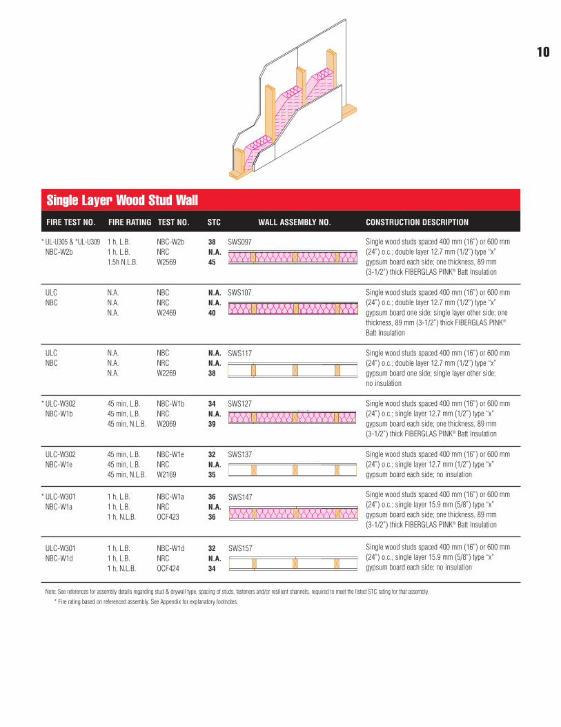
Single Layer Wood Stud Wall 9
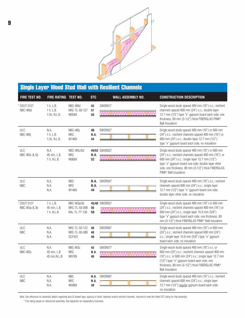
Single Layer Wood Stud Wall with Resilient Channels 10
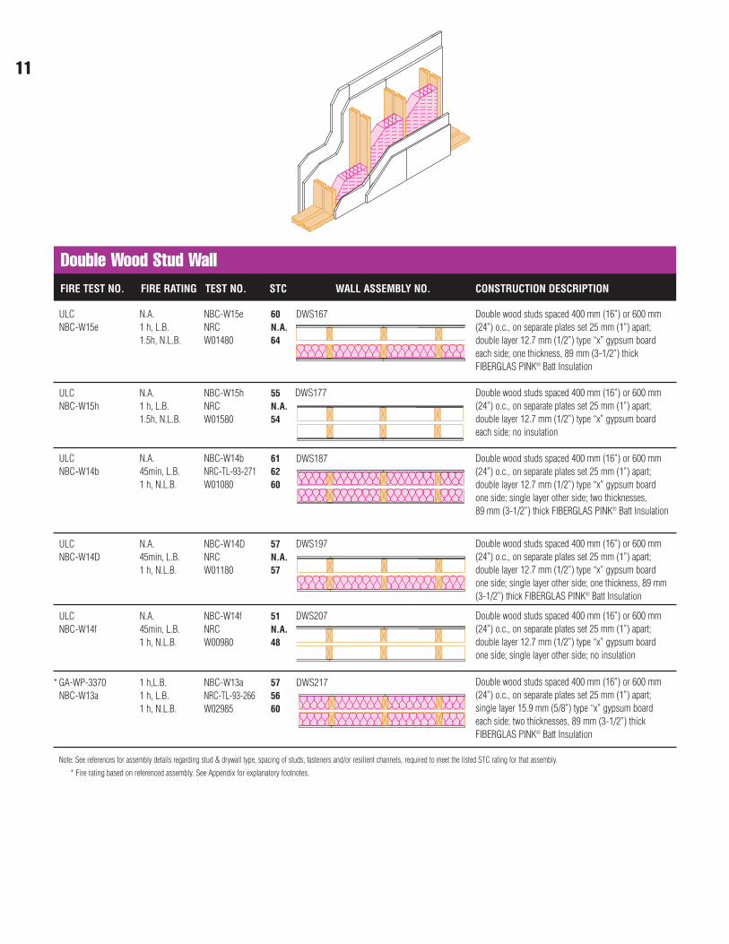
Double Wood Stud Wall 11
Single Layer Staggered Wood Stud Wall 13
Single Layer Steel Stud Wall with Resilient Channels 14
Single Layer Steel Stud Wall 15
Chase Wall 17
Double Layer Steel Stud Wall 18
Unbalanced Steel Stud Wall with Resilient Channels 20
Unbalanced Steel Stud Wall 21
Floor and Ceiling Assemblies 24
Sound Absorption Coefficients 25
Sound Transmission Loss
Exterior Walls 27
Exterior Doors & Windows 28
Appendix 29
Customer Service 34
TM &
© 1
998
U.A.
Pic
s.
The goal of all acoustically “efficient”systems is to create a living orworking environment that iscomfortable and free from distractionor unwanted external noise. While the“ideal” acoustical environment has yetto be created, several constructiondesigns for commercial andresidential installations do exist thatpromote an enhanced acousticalenvironment.
Improving the Effective Sound TransmissionLoss of Wall ConstructionsThe sound transmission loss of wallconstructions can be improved byincreasing mass, breaking the soundvibration path and providing cavityabsorption. In addition to these threemethods, another alternative approachto reduce noise levels is to add soundabsorbing materials to a room.
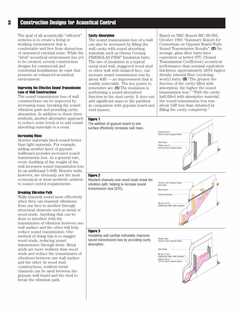
Increasing MassHeavier materials block sound betterthan light materials. For example,adding another layer of gypsumwallboard provides increased soundtransmission loss. As a general rule,every doubling of the weight of thewall increases sound transmission lossby an additional 5-6dB. Heavier walls,however, are obviously not the mosteconomical or most aesthetic solutionto sound control requirements.
Breaking Vibration PathWalls transmit sound most effectivelywhen they can transmit vibrationsfrom one face to another throughstructural elements such as metal orwood studs. Anything that can bedone to interfere with thetransmission of vibration between onewall surface and the other will helpreduce sound transmission. Onemethod of doing this is to staggerwood studs, reducing soundtransmission through them. Metalstuds are more resilient than woodstuds and reduce the transmission ofvibrations between one wall surfaceand the other. In wood studconstructions, resilient metalchannels can be used between thegypsum wall board and the stud tobreak the vibration path.
Cavity AbsorptionThe sound transmission loss of a wallcan also be increased by filling thewall cavity with sound absorbingmaterials such as Owens CorningFIBERGLAS PINK® Insulation batts.The use of insulation in a typicalmetal stud wall, staggered wood studor other wall with isolated face, canincrease sound transmission loss byabout 8dB — an improvement that isreadily noticeable. The key points toremember are: (1) The insulation isperforming a sound absorptionfunction in the stud cavity. It does notadd significant mass to the partitionin comparison with gypsum board andstud masses.
Based on NRC Report IRC-IR-693,October 1995 “Summary Report forConsortium on Gypsum Board Walls:Sound Transmission Results”. (2) Onaverage, glass fibre batts haveequivalent or better STC (SoundTransmission Coefficient) acousticalperformance than nominal equivalentthickness, approximately 265% higherdensity mineral fibre (rock/slagwool)) batts. (3) “The greater thefraction of the cavity filled withabsorption, the higher the soundtransmission loss.” “With the cavityhalf-filled with absorptive material,the sound transmission loss wasabout 5dB less than obtained by filling the cavity completely.”
3 Construction Designs for Acoustical Control
Figure 1The addition of gypsum board to one surface effectively increases wall mass.
Figure 2Resilient channels over wood studs break thevibration path, helping to increase soundtransmission loss (STC).
Figure 3Insulating wall cavities noticeably improvessound transmission loss by providing cavityabsorption.
Double layer of
Steel Studs
Wood Studs
Resilient Channels
89 mm (3-1/2")
89 mm (3-1/2")FIBERGLAS PINK® Batt Insulation
15.9 mm (5/8") Gypsum Board
Single Layer of
15.9 mm (5/8") Gypsum BoardBoth Sides
Double Layer15.9 mm (5/8")
Steel Studs
Gypsum Board
Single Layer of15.9 mm (5/8") Gypsum Board
FIBERGLAS PINK® Batt Insulation
15.9 mm (5/8") Gypsum Board
4Construction Designs for Acoustical Control
Adding Sound Absorbing Materials To Source and Receive AreasAnother method of increasing theeffective sound transmission lossbetween two rooms is to add soundabsorbing materials to each room. Bydoing this, the overall noise level ineach room is reduced, which resultsin a corresponding reduction of thesound level in any adjacent area. Byadding sound absorbing materials toboth the source and receive room,one can obtain a significant reductionof the noise level in the receive room.The net effect is a significant reductionin intruding noise, with no change tothe separating partition.
Detail Design and ConstructionConsiderationsThe effective acoustical performanceof walls can be greatly affected by anumber of design and constructiondetails. These details include sealingthe perimeter of walls, constructiondetails of wall intersections, size andplacement of windows, the locationand proper installation of doors, elec-trical outlets, ducts, and mechanicalequipment.
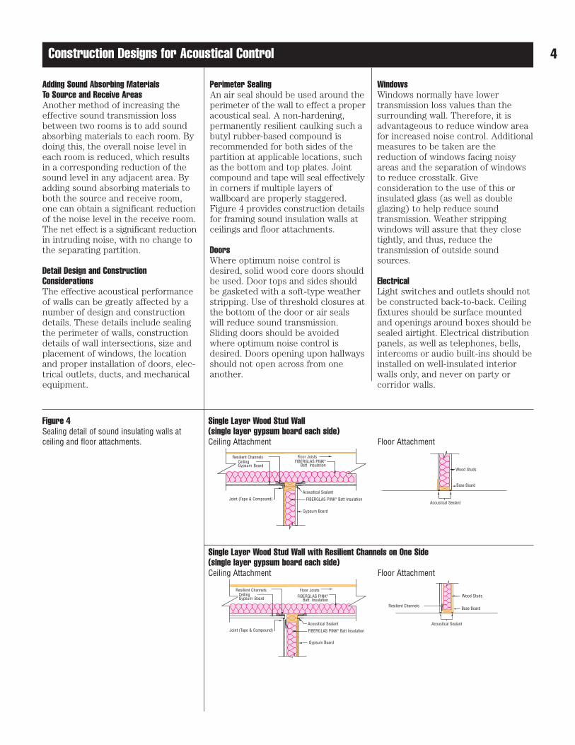
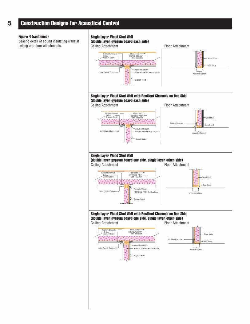
Perimeter SealingAn air seal should be used around theperimeter of the wall to effect a properacoustical seal. A non-hardening, permanently resilient caulking such abutyl rubber-based compound is recommended for both sides of thepartition at applicable locations, suchas the bottom and top plates. Jointcompound and tape will seal effectivelyin corners if multiple layers ofwallboard are properly staggered.Figure 4 provides construction detailsfor framing sound insulation walls at ceilings and floor attachments.
DoorsWhere optimum noise control isdesired, solid wood core doors shouldbe used. Door tops and sides shouldbe gasketed with a soft-type weatherstripping. Use of threshold closures atthe bottom of the door or air sealswill reduce sound transmission.Sliding doors should be avoidedwhere optimum noise control isdesired. Doors opening upon hallwaysshould not open across from oneanother.
WindowsWindows normally have lower transmission loss values than the surrounding wall. Therefore, it isadvantageous to reduce window areafor increased noise control. Additionalmeasures to be taken are thereduction of windows facing noisyareas and the separation of windowsto reduce crosstalk. Giveconsideration to the use of this orinsulated glass (as well as doubleglazing) to help reduce soundtransmission. Weather strippingwindows will assure that they closetightly, and thus, reduce thetransmission of outside soundsources.
ElectricalLight switches and outlets should notbe constructed back-to-back. Ceilingfixtures should be surface mountedand openings around boxes should besealed airtight. Electrical distributionpanels, as well as telephones, bells,intercoms or audio built-ins should beinstalled on well-insulated interiorwalls only, and never on party orcorridor walls.
Figure 4Sealing detail of sound insulating walls at ceiling and floor attachments.
Single Layer Wood Stud Wall(single layer gypsum board each side)Ceiling Attachment Floor Attachment
Single Layer Wood Stud Wall with Resilient Channels on One Side(single layer gypsum board each side)Ceiling Attachment Floor Attachment
Wood Studs
Acoustical Sealant
Base Board
Resilient Channels
Joint (Tape & Compound)Acoustical Sealant
FIBERGLAS PINK® Batt Insulation
Gypsum Board
Floor JoistsFIBERGLAS PINK®
Batt InsulationCeilingGypsum Board
Resilient Channels
Wood Studs
Acoustical Sealant
Base Board
Resilient Channels
Joint (Tape & Compound)
Acoustical Sealant
FIBERGLAS PINK® Batt Insulation
Gypsum Board
Floor JoistsFIBERGLAS PINK®
Batt InsulationCeilingGypsum Board
Resilient Channels
Joint (Tape & Compound)Acoustical SealantFIBERGLAS PINK® Batt Insulation
Gypsum Board
Floor JoistsFIBERGLAS PINK®
Batt InsulationCeilingGypsum Board Wood Studs
Acoustical Sealant
Resilient Channels Base Board
Joint (Tape & Compound)Acoustical SealantFIBERGLAS PINK® Batt Insulation
Gypsum Board
Floor Joists
Wood Studs
Acoustical Sealant
Base Board
FIBERGLAS PINK®
Batt Insulation
Joint (Tape & Compound)Acoustical Sealant
FIBERGLAS PINK® Batt Insulation
Gypsum Board
Floor Joists
Wood Studs
Acoustical Sealant
Base Board
FIBERGLAS PINK®
Batt Insulation
Resilient ChannelsCeilingGypsum Board
Resilient Channels
Joint (Tape & Compound)Acoustical Sealant
FIBERGLAS PINK® Batt Insulation
Gypsum Board
Floor JoistsFIBERGLAS PINK®
Batt InsulationCeilingGypsum Board Wood Studs
Acoustical Sealant
Resilient Channels Base Board
5 Construction Designs for Acoustical Control
Figure 4 (continued)Sealing detail of sound insulating walls at ceiling and floor attachments.
Single Layer Wood Stud Wall (double layer gypsum board each side)Ceiling Attachment Floor Attachment
Single Layer Wood Stud Wall with Resilient Channels on One Side (double layer gypsum board each side)Ceiling Attachment Floor Attachment
Single Layer Wood Stud Wall (double layer gypsum board one side, single layer other side)Ceiling Attachment Floor Attachment
Single Layer Wood Stud Wall with Resilient Channels on One Side (double layer gypsum board one side, single layer other side)Ceiling Attachment Floor Attachment
Resilient ChannelsCeilingGypsum Board
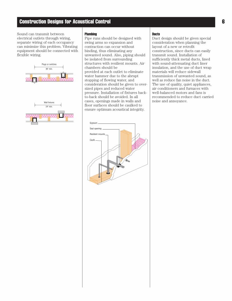
Sound can transmit betweenelectrical outlets through wiring,separate wiring of each occupancycan minimize this problem. Vibratingequipment should be connected withflexible wiring.
PlumbingPipe runs should be designed withswing arms so expansion andcontraction can occur withoutbinding, thus eliminating anyunwanted sound. Also, piping shouldbe isolated from surroundingstructures with resilient mounts. Airchambers should be provided at each outlet to eliminatewater hammer due to the abruptstopping of flowing water, andconsideration should be given to over-sized pipes and reduced waterpressure. Installation of fixtures back-to-back should be avoided. In allcases, openings made in walls andfloor surfaces should be caulked toensure optimum acoustical integrity.
DuctsDuct design should be given specialconsideration when planning thelayout of a new or retrofitconstruction, since ducts can easilytransmit sound. Installation ofsufficiently thick metal ducts, linedwith sound-attenuating duct linerinsulation, and the use of duct wrapmaterials will reduce sidewalltransmission of unwanted sound, aswell as reduce fan noise in the duct.The use of quality, quiet appliances,air conditioners and furnaces withwell-balanced motors and fans is recommended to reduce duct carriednoise and annoyance.
Plugs or switches
36"min.
Wall fixture
24"min.
Plugs or switches
36" min.
Wall fixtures
24" min.
Gypsum
Seal opening
Resilient mounts
Caulk
6Construction Designs for Acoustical Control
7
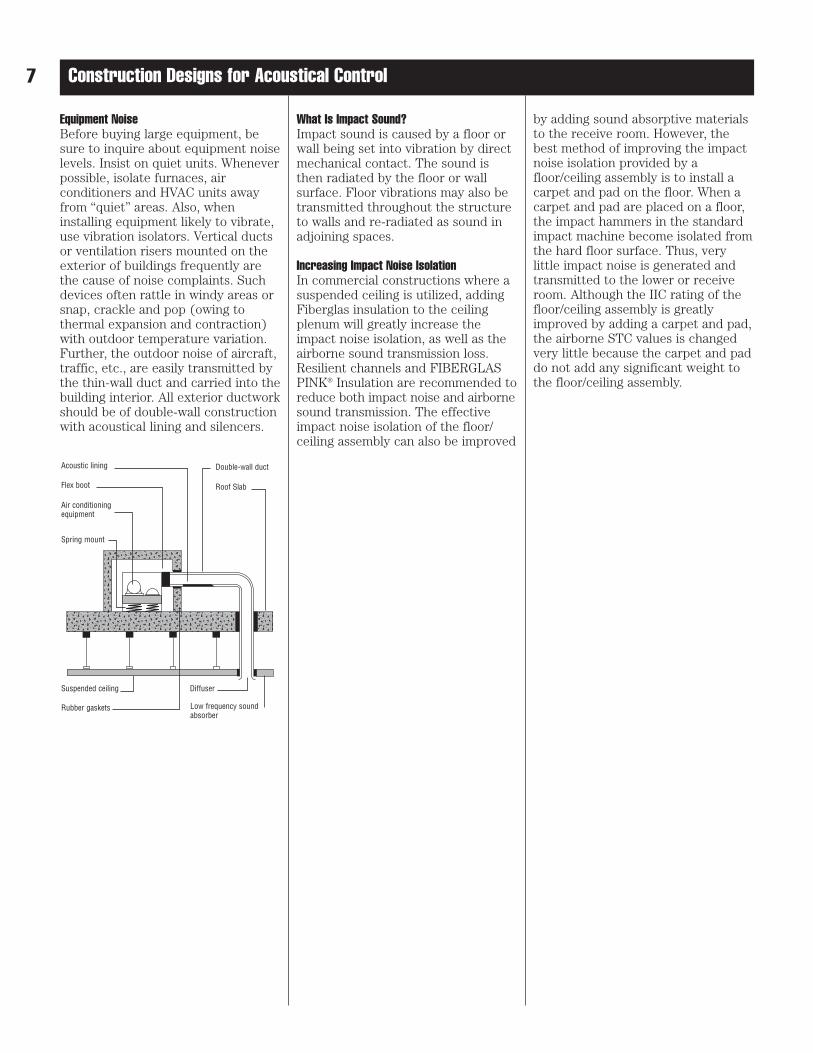
Equipment NoiseBefore buying large equipment, besure to inquire about equipment noiselevels. Insist on quiet units. Wheneverpossible, isolate furnaces, airconditioners and HVAC units awayfrom “quiet” areas. Also, wheninstalling equipment likely to vibrate,use vibration isolators. Vertical ductsor ventilation risers mounted on theexterior of buildings frequently arethe cause of noise complaints. Suchdevices often rattle in windy areas orsnap, crackle and pop (owing to thermal expansion and contraction)with outdoor temperature variation.Further, the outdoor noise of aircraft,traffic, etc., are easily transmitted bythe thin-wall duct and carried into thebuilding interior. All exterior ductworkshould be of double-wall constructionwith acoustical lining and silencers.
What Is Impact Sound?Impact sound is caused by a floor orwall being set into vibration by directmechanical contact. The sound isthen radiated by the floor or wallsurface. Floor vibrations may also betransmitted throughout the structureto walls and re-radiated as sound inadjoining spaces.
Increasing Impact Noise IsolationIn commercial constructions where asuspended ceiling is utilized, addingFiberglas insulation to the ceilingplenum will greatly increase theimpact noise isolation, as well as theairborne sound transmission loss.Resilient channels and FIBERGLASPINK® Insulation are recommended toreduce both impact noise and airbornesound transmission. The effectiveimpact noise isolation of the floor/ceiling assembly can also be improved
by adding sound absorptive materialsto the receive room. However, thebest method of improving the impactnoise isolation provided by afloor/ceiling assembly is to install acarpet and pad on the floor. When acarpet and pad are placed on a floor,the impact hammers in the standardimpact machine become isolated fromthe hard floor surface. Thus, verylittle impact noise is generated andtransmitted to the lower or receiveroom. Although the IIC rating of thefloor/ceiling assembly is greatlyimproved by adding a carpet and pad,the airborne STC values is changedvery little because the carpet and paddo not add any significant weight tothe floor/ceiling assembly.
Construction Designs for Acoustical Control
���������������������������
@@@@@@@@@@@@@@@@@@@@@@@@@@@
���������������������������
ÀÀÀÀÀÀÀÀÀÀÀÀÀÀÀÀÀÀÀÀÀÀÀÀÀÀÀ
������
@@@@@@
������
ÀÀÀÀÀÀ��
��@@@@����ÀÀÀÀ
�������������������������
@@@@@@@@@@@@@@@@@@@@@@@@@
�������������������������
ÀÀÀÀÀÀÀÀÀÀÀÀÀÀÀÀÀÀÀÀÀÀÀÀÀ
Acoustic lining
Flex boot
Air conditioningequipment
Spring mount
Suspended ceiling
Rubber gaskets
Diffuser
Low frequency soundabsorber
Double-wall duct
Roof Slab
8
Improving Ceiling Sound Transmission LossThe sound transmission loss of a ceiling can be improved by placingFiberglas insulation batts on the backof the ceiling panels. This has thesame effect as putting insulation inthe stud cavity of a wall; however, inthis case the insulation absorbs soundin the plenum area. Depending on the type of ceiling panels used, theSTC can be improved by 7 to 12points. As in the case of partitions,the effective sound transmission lossof a ceiling can also be improved byadding sound absorptive materials toboth the source and receive rooms. For example, sound absorptive walltreatments could be installed in both rooms, thereby reducing theoverall noise level.
Fuzz WallIn order to improve the two roomSTC value of a wall, considerationmust also be given to the plenumabove the dividing wall. A quick andeasy way to address this is to installthe “Fuzz wall” by stacking battsdirectly above the divider wall. For further details contact yourOwens Corning representative.
Construction Designs for Acoustical Control
References for Fire RatingULC: Underwriters Laboratories of Canada, List of Equipment & Materials,Volume III,Fire Resistance Ratings
UL: Underwriters Laboratories Inc.,Fire Resistance Directory 1997,Volume I
NBC: National Building Code of Canada, 1995, Appendix A, Table A-9.10.3.1.A
GA: Gypsum Association,Fire Resistance Design Manual,GA-600-97, 15th Edition
OSUT: The Ohio State UniversityEngineering Experiment Station
References for Sound TransmissionCoefficients (STC)NBC: National Building Code of Canada, 1995, Appendix A, Table A-9.10.3.1.A
NRC: National Research Council of Canada, Summary Report for Consortium on Gypsum Walls:Sound Transmission Results, Internal report IRC-IR-693
RAL:Riverbank Acoustical Laboratories
W & OC: Owens Corning Fiberglasacoustical Laboratory,Granville,Ohio &Acculab Consultants in Acoustics,Columbus, Ohio
Note: See references for assembly details regarding stud & drywall type, spacing of studs, fasteners and/or resilient channels, required to meet the listed STC rating for that assembly.
* Fire rating based on referenced assembly. See Appendix for explanatory footnotes.
9
Single Layer Wood Stud Wall with Resilient ChannelsFIRE TEST NO. FIRE RATING TEST NO. STC WALL ASSEMBLY NO. CONSTRUCTION DESCRIPTION
OSUT-3127 1 h, L.B. NBC-W6d 55NBC-W6d 1 h, L.B. NRC-TL-93-127 57
1.5h, N.L.B. W0569 56
Single wood studs spaced 400 mm (16”) o.c.; resilientchannels spaced 600 mm (24”) o.c.; double layer 12.7 mm (1/2”) type “x” gypsum board each side; onethickness, 89 mm (3-1/2”) thick FIBERGLAS PINK®
Batt Insulation
ULC N.A. NBC-W6j 46NBC-W6j 1 h, L.B. NRC N.A.
1.5h, N.L.B. W1469 44
Single wood studs spaced 400 mm (16”) or 600 mm(24”) o.c.; resilient channels spaced 400 mm (16”) or600 mm (24”) o.c.; double layer 12.7 mm (1/2”) type “x” gypsum board each side; no insulation
ULC N.A. NBC-W5c/5d 49/53NBC-W5c & 5d 45 min, L.B. NRC N.A.
1 h, N.L.B. W0669 52
Single wood studs spaced 400 mm (16”) or 600 mm(24”) o.c.; resilient channels spaced 400 mm (16”); or600 mm (24”) o.c.; single layer 12.7 mm (1/2”) type “x” gypsum board one side; double layer otherside, one thickness, 89 mm (3-1/2”) thick FIBERGLASPINK® Batt Insulation
ULC N.A. NBC N.A.NBC N.A. NRC N.A.
N.A. W1469 44
Single wood studs spaced 400 mm (16”) o.c.; resilientchannels spaced 600 mm (24”) o.c.; single layer 12.7 mm (1/2”) type “x” gypsum board one side;double layer other side; no insulation
OSUT-3127 1 h, L.B. NBC-W3a/3b 45/48NBC-W3a & 3b 45 min, L.B. NRC-TL-93-098 50
1 h, N.L.B. RAL-TL-77-138 50
Single wood studs spaced 400 mm (16”) or 600 mm(24”) o.c.; resilient channels spaced 400 mm (16”) or600 mm (24”) o.c.; single layer 15.9 mm (5/8”) type “x” gypsum board each side; one thickness, 89mm (3-1/2”) thick FIBERGLAS PINK® Batt Insulation
ULC N.A. NRC-TL-93-122 40NBC N.A. NRC-TL-93-089 40
N.A. OCF431 40
ULC N.A. NBC-W3c 43NBC-W3c 45 min, L.B. NRC N.A.
45 min,N.L.B. W0769 46
Single wood studs spaced 400 mm (16”) o.c. or 600 mm (24”) o.c.; resilient channels spaced 400 mm(16”) o.c. or 600 mm (24”) o.c.; single layer 12.7 mm(1/2”) type “x” gypsum board each side; onethickness, 89 mm (3-1/2”) thick FIBERGLAS PINK®
Batt Insulation
Single wood studs spaced 400 mm (16”) or 600 mm(24”) o.c.; resilient channels spaced 600 mm (24”)o.c.; single layer 15.9 mm (5/8”) type “x” gypsumboard each side; no insulation
SWSR017
SWSR027
SWSR037
SWSR047
SWSR057
SWSR067
SWSR077
ULC N.A. NBC N.A.NBC N.A. NRC N.A.
N.A. W0969 39
Single wood studs spaced 400 mm (16”) o.c.; resilientchannels spaced 600 mm (24”) o.c.; single layer 12.7 mm (1/2”) regular gypsum board each side; no insulation
SWSR087
*
*
10
Note: See references for assembly details regarding stud & drywall type, spacing of studs, fasteners and/or resilient channels, required to meet the listed STC rating for that assembly.
* Fire rating based on referenced assembly. See Appendix for explanatory footnotes.
FIRE TEST NO. FIRE RATING TEST NO. STC WALL ASSEMBLY NO. CONSTRUCTION DESCRIPTION
Single Layer Wood Stud Wall
UL-U305 & *UL-U309 1 h, L.B. NBC-W2b 38NBC-W2b 1 h, L.B. NRC N.A. SWS097
1.5h N.L.B. W2569 45
Single wood studs spaced 400 mm (16”) or 600 mm(24”) o.c.; double layer 12.7 mm (1/2”) type “x”gypsum board each side; one thickness, 89 mm (3-1/2”) thick FIBERGLAS PINK® Batt Insulation
ULC N.A. NBC N.A.NBC N.A. NRC N.A. SWS107
N.A. W2469 40
Single wood studs spaced 400 mm (16”) or 600 mm(24”) o.c.; double layer 12.7 mm (1/2”) type “x”gypsum board one side; single layer other side; onethickness, 89 mm (3-1/2”) thick FIBERGLAS PINK®
Batt Insulation
ULC N.A. NBC N.A.NBC N.A. NRC N.A.
N.A. W2269 38
Single wood studs spaced 400 mm (16”) or 600 mm(24”) o.c.; double layer 12.7 mm (1/2”) type “x”gypsum board one side; single layer other side; no insulation
ULC-W302 45 min, L.B. NBC-W1b 34NBC-W1b 45 min, L.B. NRC N.A. SWS127
45 min, N.L.B. W2069 39
Single wood studs spaced 400 mm (16”) or 600 mm(24”) o.c.; single layer 12.7 mm (1/2”) type “x”gypsum board each side; one thickness, 89 mm (3-1/2”) thick FIBERGLAS PINK® Batt Insulation
ULC-W302 45 min, L.B. NBC-W1e 32NBC-W1e 45 min, L.B. NRC N.A. SWS137
45 min, N.L.B. W2169 35
Single wood studs spaced 400 mm (16”) or 600 mm(24”) o.c.; single layer 12.7 mm (1/2”) type “x”gypsum board each side; no insulation
ULC-W301 1 h, L.B. NBC-W1a 36NBC-W1a 1 h, L.B. NRC N.A. SWS147
1 h, N.L.B. OCF423 36
ULC-W301 1 h, L.B. NBC-W1d 32NBC-W1d 1 h, L.B. NRC N.A. SWS157
1 h, N.L.B. OCF424 34
Single wood studs spaced 400 mm (16”) or 600 mm(24”) o.c.; single layer 15.9 mm (5/8”) type “x”gypsum board each side; no insulation
Single wood studs spaced 400 mm (16”) or 600 mm(24”) o.c.; single layer 15.9 mm (5/8”) type “x”gypsum board each side; one thickness, 89 mm (3-1/2”) thick FIBERGLAS PINK® Batt Insulation
SWS097
SWS107
SWS117
SWS127
SWS137
SWS147
SWS157
*
*
*
Note: See references for assembly details regarding stud & drywall type, spacing of studs, fasteners and/or resilient channels, required to meet the listed STC rating for that assembly.
* Fire rating based on referenced assembly. See Appendix for explanatory footnotes.
11
FIRE TEST NO. FIRE RATING TEST NO. STC WALL ASSEMBLY NO. CONSTRUCTION DESCRIPTION
Double Wood Stud Wall
ULC N.A. NBC-W15e 60NBC-W15e 1 h, L.B. NRC N.A.
1.5h, N.L.B. W01480 64
Double wood studs spaced 400 mm (16”) or 600 mm(24”) o.c., on separate plates set 25 mm (1”) apart;double layer 12.7 mm (1/2”) type “x” gypsum boardeach side; one thickness, 89 mm (3-1/2”) thickFIBERGLAS PINK® Batt Insulation
ULC N.A. NBC-W15h 55NBC-W15h 1 h, L.B. NRC N.A.
1.5h, N.L.B. W01580 54
Double wood studs spaced 400 mm (16”) or 600 mm(24”) o.c., on separate plates set 25 mm (1”) apart;double layer 12.7 mm (1/2”) type “x” gypsum boardeach side; no insulation
ULC N.A. NBC-W14b 61NBC-W14b 45min, L.B. NRC-TL-93-271 62
1 h, N.L.B. W01080 60
Double wood studs spaced 400 mm (16”) or 600 mm(24”) o.c., on separate plates set 25 mm (1”) apart;double layer 12.7 mm (1/2”) type “x” gypsum boardone side; single layer other side; two thicknesses, 89 mm (3-1/2”) thick FIBERGLAS PINK® Batt Insulation
ULC N.A. NBC-W14D 57NBC-W14D 45min, L.B. NRC N.A.
1 h, N.L.B. W01180 57
Double wood studs spaced 400 mm (16”) or 600 mm(24”) o.c., on separate plates set 25 mm (1”) apart;double layer 12.7 mm (1/2”) type “x” gypsum boardone side; single layer other side; one thickness, 89 mm(3-1/2”) thick FIBERGLAS PINK® Batt Insulation
ULC N.A. NBC-W14f 51NBC-W14f 45min, L.B. NRC N.A.
1 h, N.L.B. W00980 48
Double wood studs spaced 400 mm (16”) or 600 mm(24”) o.c., on separate plates set 25 mm (1”) apart;double layer 12.7 mm (1/2”) type “x” gypsum boardone side; single layer other side; no insulation
GA-WP-3370 1 h,L.B. NBC-W13a 57NBC-W13a 1 h, L.B. NRC-TL-93-266 56 DWS217
1 h, N.L.B. W02985 60
Double wood studs spaced 400 mm (16”) or 600 mm(24”) o.c., on separate plates set 25 mm (1”) apart;single layer 15.9 mm (5/8”) type “x” gypsum boardeach side; two thicknesses, 89 mm (3-1/2”) thickFIBERGLAS PINK® Batt Insulation
DWS167
DWS177
DWS187
DWS197
DWS207
DWS217*
Note: See references for assembly details regarding stud & drywall type, spacing of studs, fasteners and/or resilient channels, required to meet the listed STC rating for that assembly.
* Fire rating based on referenced assembly. See Appendix for explanatory footnotes.
12
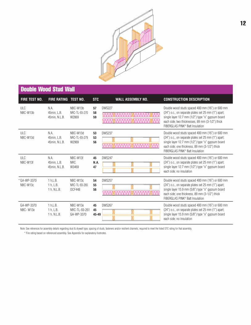
Double Wood Stud WallFIRE TEST NO. FIRE RATING TEST NO. STC WALL ASSEMBLY NO. CONSTRUCTION DESCRIPTION
ULC N.A. NBC-W13b 57NBC-W13b 45min, L.B. NRC-TL-93-270 58
45min, N.L.B. W2869 59
Double wood studs spaced 400 mm (16”) or 600 mm(24”) o.c., on separate plates set 25 mm (1”) apart;single layer 12.7 mm (1/2”) type “x” gypsum boardeach side; two thicknesses, 89 mm (3-1/2”) thickFIBERGLAS PINK® Batt Insulation
ULC N.A. NBC-W13d 53NBC-W13d 45min, L.B. NRC-TL-93-279 53
45min, N.L.B. W2969 56
Double wood studs spaced 400 mm (16”) or 600 mm(24”) o.c., on separate plates set 25 mm (1”) apart;single layer 12.7 mm (1/2”) type “x” gypsum boardeach side; one thickness, 89 mm (3-1/2”) thickFIBERGLAS PINK® Batt Insulation
ULC N.A. NBC-W13f 45NBC-W13f 45min, L.B. NRC N.A.
45min, N.L.B. W3469 47
Double wood studs spaced 400 mm (16”) or 600 mm(24”) o.c., on separate plates set 25 mm (1”) apart;single layer 12.7 mm (1/2”) type “x” gypsum boardeach side; no insulation
GA-WP-3370 1 h,L.B. NBC-W13c 54NBC-W13c 1 h, L.B. NRC-TL-93-265 55
1 h, N.L.B. OCF448 56
Double wood studs spaced 400 mm (16”) or 600 mm(24”) o.c., on separate plates set 25 mm (1”) apart;single layer 15.9 mm (5/8”) type “x” gypsum boardeach side; one thickness, 89 mm (3-1/2”) thickFIBERGLAS PINK® Batt Insulation
GA-WP-3370 1 h,L.B. NBC-W13e 45NBC- W13e 1 h, L.B. NRC-TL-93-261 45
1 h, N.L.B. GA-WP-3370 45-49
Double wood studs spaced 400 mm (16”) or 600 mm(24”) o.c., on separate plates set 25 mm (1”) apart;single layer 15.9 mm (5/8”) type “x” gypsum boardeach side; no insulation
DWS227
DWS237
DWS247
DWS257
DWS267
*
13
Note: See references for assembly details regarding stud & drywall type, spacing of studs, fasteners and/or resilient channels, required to meet the listed STC rating for that assembly.
* Fire rating based on referenced assembly. See Appendix for explanatory footnotes.
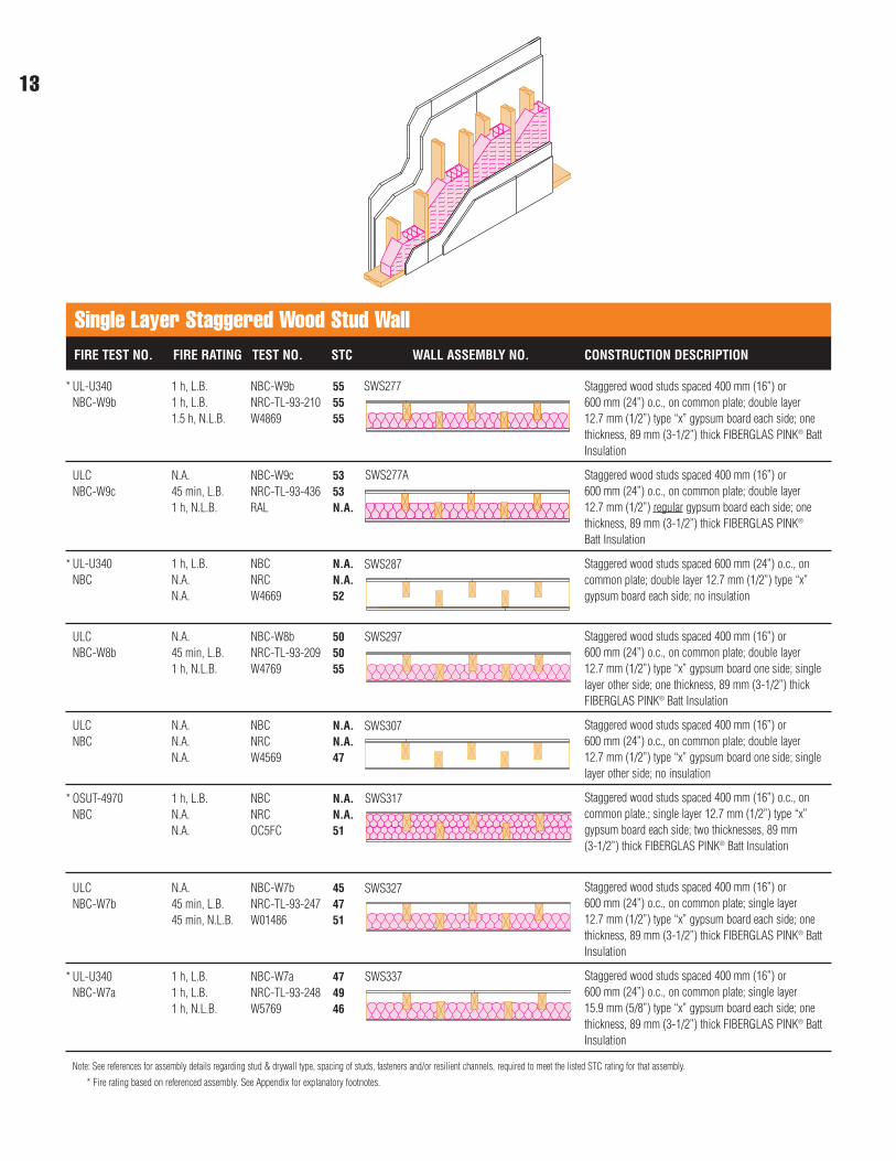
FIRE TEST NO. FIRE RATING TEST NO. STC WALL ASSEMBLY NO. CONSTRUCTION DESCRIPTION
Single Layer Staggered Wood Stud Wall
UL-U340 1 h, L.B. NBC-W9b 55NBC-W9b 1 h, L.B. NRC-TL-93-210 55
1.5 h, N.L.B. W4869 55
Staggered wood studs spaced 400 mm (16”) or 600 mm (24”) o.c., on common plate; double layer 12.7 mm (1/2”) type “x” gypsum board each side; onethickness, 89 mm (3-1/2”) thick FIBERGLAS PINK® BattInsulation
ULC N.A. NBC-W9c 53NBC-W9c 45 min, L.B. NRC-TL-93-436 53
1 h, N.L.B. RAL N.A.
Staggered wood studs spaced 400 mm (16”) or 600 mm (24”) o.c., on common plate; double layer 12.7 mm (1/2”) regular gypsum board each side; onethickness, 89 mm (3-1/2”) thick FIBERGLAS PINK®
Batt Insulation
UL-U340 1 h, L.B. NBC N.A.NBC N.A. NRC N.A.
N.A. W4669 52
Staggered wood studs spaced 600 mm (24”) o.c., oncommon plate; double layer 12.7 mm (1/2”) type “x”gypsum board each side; no insulation
ULC N.A. NBC-W8b 50NBC-W8b 45 min, L.B. NRC-TL-93-209 50
1 h, N.L.B. W4769 55
Staggered wood studs spaced 400 mm (16”) or 600 mm (24”) o.c., on common plate; double layer 12.7 mm (1/2”) type “x” gypsum board one side; singlelayer other side; one thickness, 89 mm (3-1/2”) thickFIBERGLAS PINK® Batt Insulation
ULC N.A. NBC N.A.NBC N.A. NRC N.A.
N.A. W4569 47
Staggered wood studs spaced 400 mm (16”) or 600 mm (24”) o.c., on common plate; double layer 12.7 mm (1/2”) type “x” gypsum board one side; singlelayer other side; no insulation
OSUT-4970 1 h, L.B. NBC N.A.NBC N.A. NRC N.A.
N.A. OC5FC 51
Staggered wood studs spaced 400 mm (16”) o.c., oncommon plate.; single layer 12.7 mm (1/2”) type “x”gypsum board each side; two thicknesses, 89 mm (3-1/2”) thick FIBERGLAS PINK® Batt Insulation
SWS277
SWS277A
SWS287
SWS297
SWS307
SWS317
ULC N.A. NBC-W7b 45NBC-W7b 45 min, L.B. NRC-TL-93-247 47
45 min, N.L.B. W01486 51
Staggered wood studs spaced 400 mm (16”) or 600 mm (24”) o.c., on common plate; single layer 12.7 mm (1/2”) type “x” gypsum board each side; onethickness, 89 mm (3-1/2”) thick FIBERGLAS PINK® BattInsulation
SWS327
UL-U340 1 h, L.B. NBC-W7a 47NBC-W7a 1 h, L.B. NRC-TL-93-248 49
1 h, N.L.B. W5769 46
Staggered wood studs spaced 400 mm (16”) or 600 mm (24”) o.c., on common plate; single layer 15.9 mm (5/8”) type “x” gypsum board each side; onethickness, 89 mm (3-1/2”) thick FIBERGLAS PINK® BattInsulation
SWS337
*
*
*
*
14
Note: See references for assembly details regarding stud & drywall type, spacing of studs, fasteners and/or resilient channels, required to meet the listed STC rating for that assembly.
* Fire rating based on referenced assembly. See Appendix for explanatory footnotes.
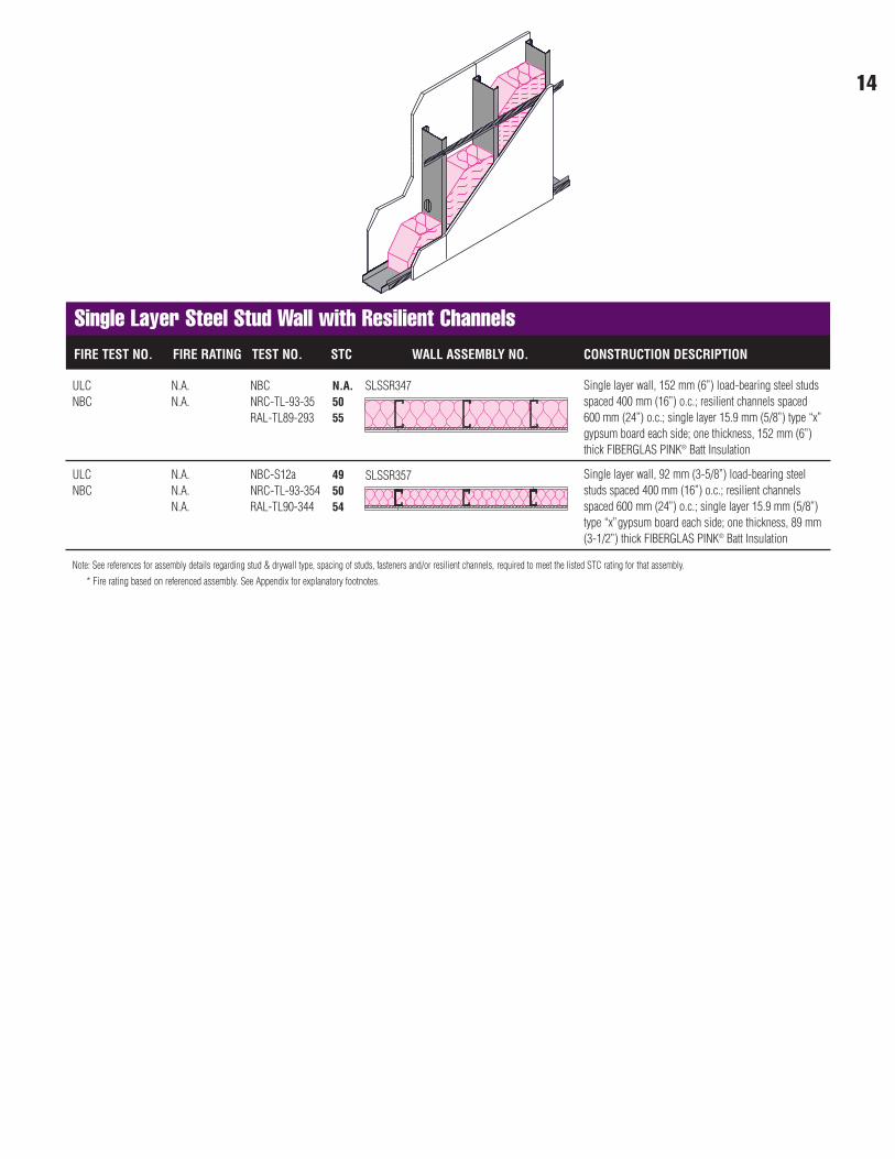
Single Layer Steel Stud Wall with Resilient ChannelsFIRE TEST NO. FIRE RATING TEST NO. STC WALL ASSEMBLY NO. CONSTRUCTION DESCRIPTION
ULC N.A. NBC N.A.NBC N.A. NRC-TL-93-35 50
RAL-TL89-293 55
Single layer wall, 152 mm (6”) load-bearing steel studsspaced 400 mm (16”) o.c.; resilient channels spaced600 mm (24”) o.c.; single layer 15.9 mm (5/8”) type “x”gypsum board each side; one thickness, 152 mm (6”)thick FIBERGLAS PINK® Batt Insulation
ULC N.A. NBC-S12a 49NBC N.A. NRC-TL-93-354 50
N.A. RAL-TL90-344 54
Single layer wall, 92 mm (3-5/8”) load-bearing steelstuds spaced 400 mm (16”) o.c.; resilient channelsspaced 600 mm (24”) o.c.; single layer 15.9 mm (5/8”)type “x”gypsum board each side; one thickness, 89 mm(3-1/2”) thick FIBERGLAS PINK® Batt Insulation
SLSSR347
SLSSR357
15
Note: See references for assembly details regarding stud & drywall type, spacing of studs, fasteners and/or resilient channels, required to meet the listed STC rating for that assembly.
* Fire rating based on referenced assembly. See Appendix for explanatory footnotes.
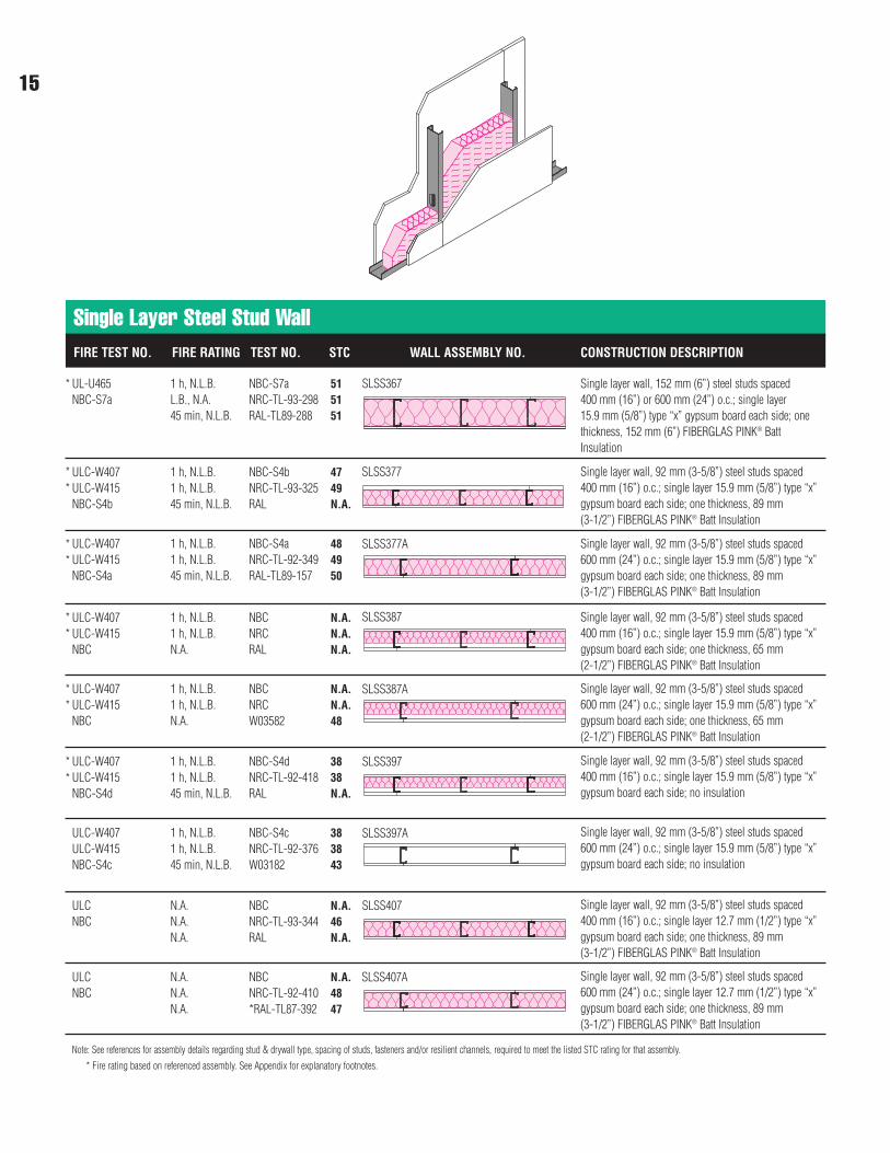
FIRE TEST NO. FIRE RATING TEST NO. STC WALL ASSEMBLY NO. CONSTRUCTION DESCRIPTION
Single Layer Steel Stud Wall
UL-U465 1 h, N.L.B. NBC-S7a 51NBC-S7a L.B., N.A. NRC-TL-93-298 51
45 min, N.L.B. RAL-TL89-288 51
Single layer wall, 152 mm (6”) steel studs spaced 400 mm (16”) or 600 mm (24”) o.c.; single layer 15.9 mm (5/8”) type “x” gypsum board each side; onethickness, 152 mm (6”) FIBERGLAS PINK® BattInsulation
ULC-W407 1 h, N.L.B. NBC-S4b 47ULC-W415 1 h, N.L.B. NRC-TL-93-325 49NBC-S4b 45 min, N.L.B. RAL N.A.
Single layer wall, 92 mm (3-5/8”) steel studs spaced400 mm (16”) o.c.; single layer 15.9 mm (5/8”) type “x”gypsum board each side; one thickness, 89 mm (3-1/2”) FIBERGLAS PINK® Batt Insulation
ULC-W407 1 h, N.L.B. NBC-S4a 48ULC-W415 1 h, N.L.B. NRC-TL-92-349 49NBC-S4a 45 min, N.L.B. RAL-TL89-157 50
Single layer wall, 92 mm (3-5/8”) steel studs spaced600 mm (24”) o.c.; single layer 15.9 mm (5/8”) type “x”gypsum board each side; one thickness, 89 mm (3-1/2”) FIBERGLAS PINK® Batt Insulation
SLSS367
SLSS377
SLSS377A
ULC-W407 1 h, N.L.B. NBC N.A.ULC-W415 1 h, N.L.B. NRC N.A.NBC N.A. RAL N.A.
Single layer wall, 92 mm (3-5/8”) steel studs spaced400 mm (16”) o.c.; single layer 15.9 mm (5/8”) type “x”gypsum board each side; one thickness, 65 mm (2-1/2”) FIBERGLAS PINK® Batt Insulation
ULC-W407 1 h, N.L.B. NBC N.A.ULC-W415 1 h, N.L.B. NRC N.A.NBC N.A. W03582 48
Single layer wall, 92 mm (3-5/8”) steel studs spaced600 mm (24”) o.c.; single layer 15.9 mm (5/8”) type “x”gypsum board each side; one thickness, 65 mm (2-1/2”) FIBERGLAS PINK® Batt Insulation
ULC-W407 1 h, N.L.B. NBC-S4d 38ULC-W415 1 h, N.L.B. NRC-TL-92-418 38NBC-S4d 45 min, N.L.B. RAL N.A.
Single layer wall, 92 mm (3-5/8”) steel studs spaced400 mm (16”) o.c.; single layer 15.9 mm (5/8”) type “x”gypsum board each side; no insulation
SLSS387
SLSS387A
SLSS397
ULC-W407 1 h, N.L.B. NBC-S4c 38ULC-W415 1 h, N.L.B. NRC-TL-92-376 38NBC-S4c 45 min, N.L.B. W03182 43
Single layer wall, 92 mm (3-5/8”) steel studs spaced600 mm (24”) o.c.; single layer 15.9 mm (5/8”) type “x”gypsum board each side; no insulation
SLSS397A
ULC N.A. NBC N.A.NBC N.A. NRC-TL-93-344 46
N.A. RAL N.A.
Single layer wall, 92 mm (3-5/8”) steel studs spaced400 mm (16”) o.c.; single layer 12.7 mm (1/2”) type “x”gypsum board each side; one thickness, 89 mm (3-1/2”) FIBERGLAS PINK® Batt Insulation
SLSS407
ULC N.A. NBC N.A.NBC N.A. NRC-TL-92-410 48
N.A. *RAL-TL87-392 47
Single layer wall, 92 mm (3-5/8”) steel studs spaced600 mm (24”) o.c.; single layer 12.7 mm (1/2”) type “x”gypsum board each side; one thickness, 89 mm (3-1/2”) FIBERGLAS PINK® Batt Insulation
SLSS407A
*
**
**
**
**
**
16
Note: See references for assembly details regarding stud & drywall type, spacing of studs, fasteners and/or resilient channels, required to meet the listed STC rating for that assembly.
* Fire rating based on referenced assembly. See Appendix for explanatory footnotes.
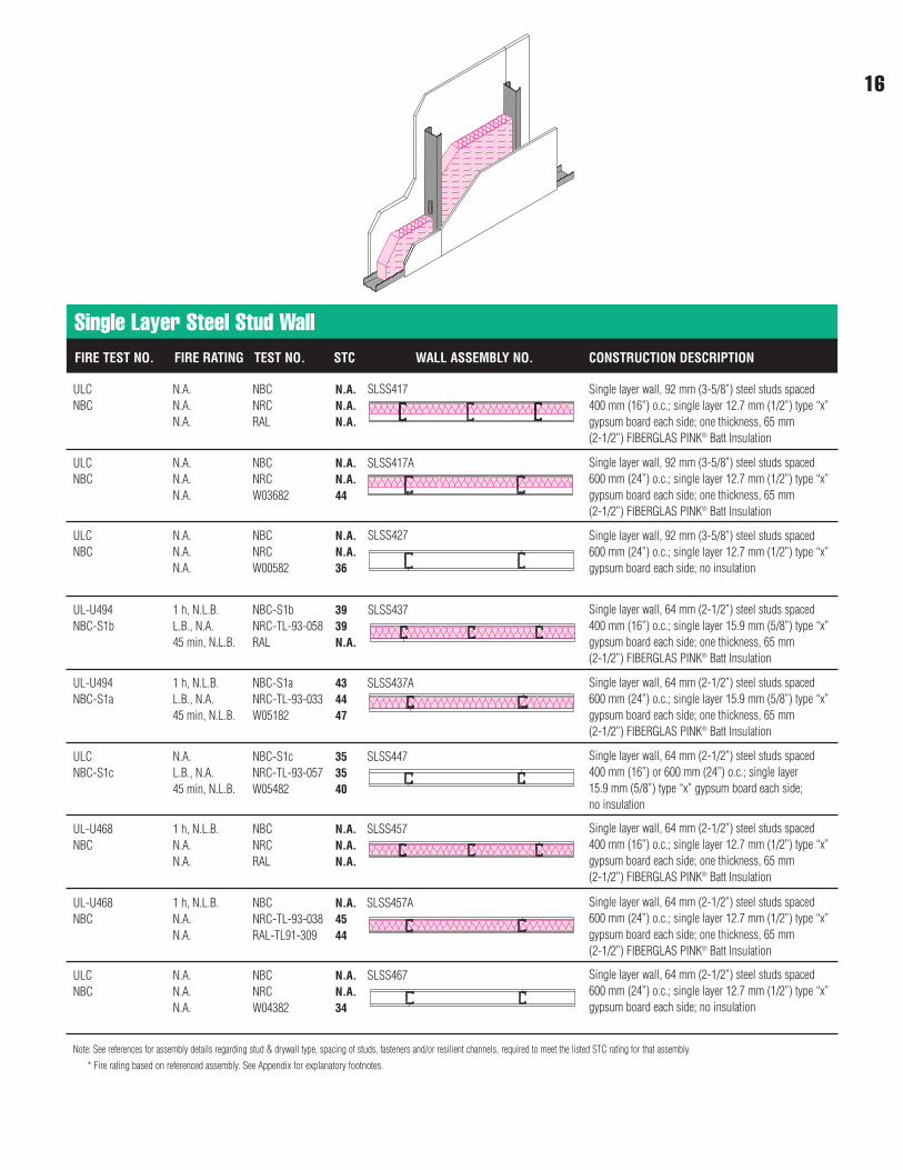
FIRE TEST NO. FIRE RATING TEST NO. STC WALL ASSEMBLY NO. CONSTRUCTION DESCRIPTION
Single Layer Steel Stud Wall
ULC N.A. NBC N.A.NBC N.A. NRC N.A.
N.A. RAL N.A.
Single layer wall, 92 mm (3-5/8”) steel studs spaced400 mm (16”) o.c.; single layer 12.7 mm (1/2”) type “x”gypsum board each side; one thickness, 65 mm (2-1/2”) FIBERGLAS PINK® Batt Insulation
ULC N.A. NBC N.A.NBC N.A. NRC N.A.
N.A. W03682 44
Single layer wall, 92 mm (3-5/8”) steel studs spaced600 mm (24”) o.c.; single layer 12.7 mm (1/2”) type “x”gypsum board each side; one thickness, 65 mm (2-1/2”) FIBERGLAS PINK® Batt Insulation
ULC N.A. NBC N.A.NBC N.A. NRC N.A.
N.A. W00582 36
Single layer wall, 92 mm (3-5/8”) steel studs spaced600 mm (24”) o.c.; single layer 12.7 mm (1/2”) type “x”gypsum board each side; no insulation
SLSS417
SLSS417A
SLSS427
UL-U494 1 h, N.L.B. NBC-S1b 39NBC-S1b L.B., N.A. NRC-TL-93-058 39
45 min, N.L.B. RAL N.A.
Single layer wall, 64 mm (2-1/2”) steel studs spaced400 mm (16”) o.c.; single layer 15.9 mm (5/8”) type “x”gypsum board each side; one thickness, 65 mm (2-1/2”) FIBERGLAS PINK® Batt Insulation
UL-U494 1 h, N.L.B. NBC-S1a 43NBC-S1a L.B., N.A. NRC-TL-93-033 44
45 min, N.L.B. W05182 47
Single layer wall, 64 mm (2-1/2”) steel studs spaced600 mm (24”) o.c.; single layer 15.9 mm (5/8”) type “x”gypsum board each side; one thickness, 65 mm (2-1/2”) FIBERGLAS PINK® Batt Insulation
ULC N.A. NBC-S1c 35NBC-S1c L.B., N.A. NRC-TL-93-057 35
45 min, N.L.B. W05482 40
Single layer wall, 64 mm (2-1/2”) steel studs spaced400 mm (16”) or 600 mm (24”) o.c.; single layer 15.9 mm (5/8”) type “x” gypsum board each side; no insulation
SLSS437
SLSS437A
SLSS447
UL-U468 1 h, N.L.B. NBC N.A.NBC N.A. NRC N.A.
N.A. RAL N.A.
Single layer wall, 64 mm (2-1/2”) steel studs spaced400 mm (16”) o.c.; single layer 12.7 mm (1/2”) type “x”gypsum board each side; one thickness, 65 mm (2-1/2”) FIBERGLAS PINK® Batt Insulation
SLSS457
UL-U468 1 h, N.L.B. NBC N.A.NBC N.A. NRC-TL-93-038 45
N.A. RAL-TL91-309 44
Single layer wall, 64 mm (2-1/2”) steel studs spaced600 mm (24”) o.c.; single layer 12.7 mm (1/2”) type “x”gypsum board each side; one thickness, 65 mm (2-1/2”) FIBERGLAS PINK® Batt Insulation
SLSS457A
ULC N.A. NBC N.A.NBC N.A. NRC N.A.
N.A. W04382 34
Single layer wall, 64 mm (2-1/2”) steel studs spaced600 mm (24”) o.c.; single layer 12.7 mm (1/2”) type “x”gypsum board each side; no insulation
SLSS467
Note: See references for assembly details regarding stud & drywall type, spacing of studs, fasteners and/or resilient channels, required to meet the listed STC rating for that assembly.
* Fire rating based on referenced assembly. See Appendix for explanatory footnotes.
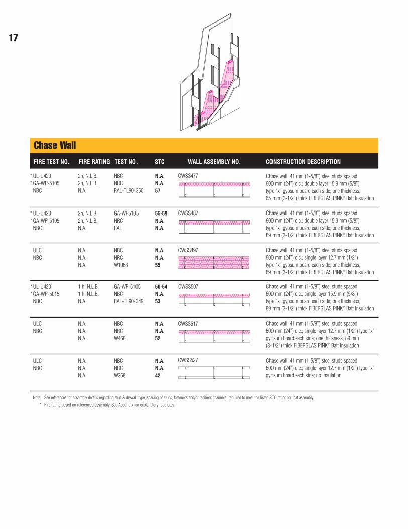
Chase WallFIRE TEST NO. FIRE RATING TEST NO. STC WALL ASSEMBLY NO. CONSTRUCTION DESCRIPTION
UL-U420 2h, N.L.B. NBC N.A.GA-WP-5105 2h, N.L.B. NRC N.A.NBC N.A. RAL-TL90-350 57
UL-U420 2h, N.L.B. GA-WP5105 55-59GA-WP-5105 2h, N.L.B. NRC N.A.NBC N.A. RAL N.A.
Chase wall, 41 mm (1-5/8”) steel studs spaced 600 mm (24”) o.c.; double layer 15.9 mm (5/8”) type “x” gypsum board each side; one thickness, 89 mm (3-1/2”) thick FIBERGLAS PINK® Batt Insulation
Chase wall, 41 mm (1-5/8”) steel studs spaced 600 mm (24”) o.c.; double layer 15.9 mm (5/8”) type “x” gypsum board each side; one thickness, 65 mm (2-1/2”) thick FIBERGLAS PINK® Batt Insulation
ULC N.A. NBC N.A.NBC N.A. NRC N.A.
N.A. W1068 55
Chase wall, 41 mm (1-5/8”) steel studs spaced 600 mm (24”) o.c.; single layer 12.7 mm (1/2”) type “x” gypsum board each side; one thickness, 89 mm (3-1/2”) thick FIBERGLAS PINK® Batt Insulation
UL-U420 1 h, N.L.B. GA-WP-5105 50-54GA-WP-5015 1 h, N.L.B. NBC N.A.NBC N.A. RAL-TL90-349 53
Chase wall, 41 mm (1-5/8”) steel studs spaced 600 mm (24”) o.c.; single layer 15.9 mm (5/8”) type “x” gypsum board each side; one thickness, 89 mm (3-1/2”) thick FIBERGLAS PINK® Batt Insulation
ULC N.A. NBC N.A.NBC N.A. NRC N.A.
N.A. W468 52
Chase wall, 41 mm (1-5/8”) steel studs spaced 600 mm (24”) o.c.; single layer 12.7 mm (1/2”) type “x”gypsum board each side; one thickness, 89 mm (3-1/2”) thick FIBERGLAS PINK® Batt Insulation
ULC N.A. NBC N.A.NBC N.A. NRC N.A.
N.A. W368 42
Chase wall, 41 mm (1-5/8”) steel studs spaced 600 mm (24”) o.c.; single layer 12.7 mm (1/2”) type “x”gypsum board each side; no insulation
CWSS487
CWSS507
**
**
**
CWSS477
CWSS497
CWSS517
CWSS527
17
18
Note: See references for assembly details regarding stud & drywall type, spacing of studs, fasteners and/or resilient channels, required to meet the listed STC rating for that assembly.
* Fire rating based on referenced assembly. See Appendix for explanatory footnotes.
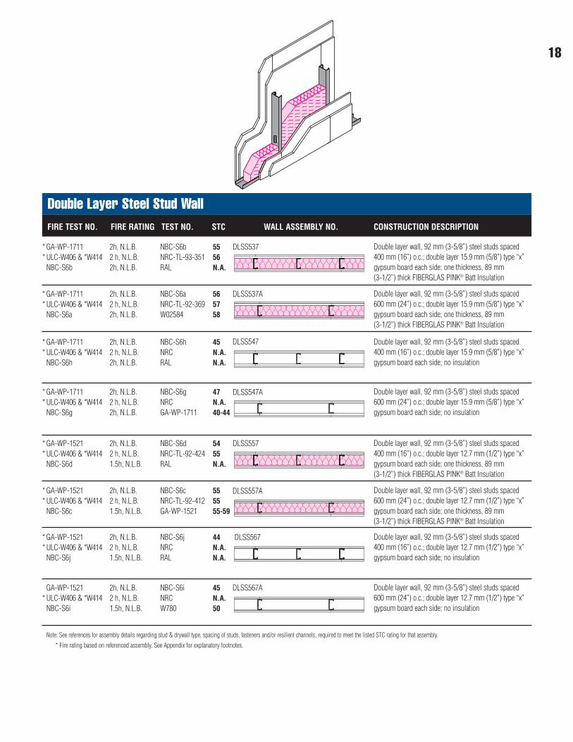
Double Layer Steel Stud WallFIRE TEST NO. FIRE RATING TEST NO. STC WALL ASSEMBLY NO. CONSTRUCTION DESCRIPTION
GA-WP-1711 2h, N.L.B. NBC-S6b 55ULC-W406 & *W414 2 h, N.L.B. NRC-TL-93-351 56NBC-S6b 2h, N.L.B. RAL N.A.
Double layer wall, 92 mm (3-5/8”) steel studs spaced400 mm (16”) o.c.; double layer 15.9 mm (5/8”) type “x”gypsum board each side; one thickness, 89 mm (3-1/2”) thick FIBERGLAS PINK® Batt Insulation
GA-WP-1711 2h, N.L.B. NBC-S6a 56ULC-W406 & *W414 2 h, N.L.B. NRC-TL-92-369 57NBC-S6a 2h, N.L.B. W02584 58
Double layer wall, 92 mm (3-5/8”) steel studs spaced600 mm (24”) o.c.; double layer 15.9 mm (5/8”) type “x”gypsum board each side; one thickness, 89 mm (3-1/2”) thick FIBERGLAS PINK® Batt Insulation
GA-WP-1711 2h, N.L.B. NBC-S6h 45ULC-W406 & *W414 2 h, N.L.B. NRC N.A.NBC-S6h 2h, N.L.B. RAL N.A.
Double layer wall, 92 mm (3-5/8”) steel studs spaced400 mm (16”) o.c.; double layer 15.9 mm (5/8”) type “x”gypsum board each side; no insulation
GA-WP-1711 2h, N.L.B. NBC-S6g 47ULC-W406 & *W414 2 h, N.L.B. NRC N.A.NBC-S6g 2h, N.L.B. GA-WP-1711 40-44
Double layer wall, 92 mm (3-5/8”) steel studs spaced600 mm (24”) o.c.; double layer 15.9 mm (5/8”) type “x”gypsum board each side; no insulation
GA-WP-1521 2h, N.L.B. NBC-S6d 54ULC-W406 & *W414 2 h, N.L.B. NRC-TL-92-424 55NBC-S6d 1.5h, N.L.B. RAL N.A.
Double layer wall, 92 mm (3-5/8”) steel studs spaced400 mm (16”) o.c.; double layer 12.7 mm (1/2”) type “x”gypsum board each side; one thickness, 89 mm (3-1/2”) thick FIBERGLAS PINK® Batt Insulation
GA-WP-1521 2h, N.L.B. NBC-S6c 55ULC-W406 & *W414 2 h, N.L.B. NRC-TL-92-412 55NBC-S6c 1.5h, N.L.B. GA-WP-1521 55-59
GA-WP-1521 2h, N.L.B. NBC-S6j 44ULC-W406 & *W414 2 h, N.L.B. NRC N.A.NBC-S6j 1.5h, N.L.B. RAL N.A.
Double layer wall, 92 mm (3-5/8”) steel studs spaced400 mm (16”) o.c.; double layer 12.7 mm (1/2”) type “x”gypsum board each side; no insulation
Double layer wall, 92 mm (3-5/8”) steel studs spaced600 mm (24”) o.c.; double layer 12.7 mm (1/2”) type “x”gypsum board each side; one thickness, 89 mm (3-1/2”) thick FIBERGLAS PINK® Batt Insulation
DLSS537
DLSS537A
DLSS547
DLSS547A
DLSS557
DLSS557A
DLSS567
GA-WP-1521 2h, N.L.B. NBC-S6i 45ULC-W406 & *W414 2 h, N.L.B. NRC N.A.NBC-S6i 1.5h, N.L.B. W780 50
Double layer wall, 92 mm (3-5/8”) steel studs spaced600 mm (24”) o.c.; double layer 12.7 mm (1/2”) type “x”gypsum board each side; no insulation
DLSS567A
**
**
**
**
**
**
**
*
Note: See references for assembly details regarding stud & drywall type, spacing of studs, fasteners and/or resilient channels, required to meet the listed STC rating for that assembly.
* Fire rating based on referenced assembly. See Appendix for explanatory footnotes.
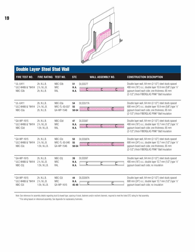
Double Layer Steel Stud WallFIRE TEST NO. FIRE RATING TEST NO. STC WALL ASSEMBLY NO. CONSTRUCTION DESCRIPTION
UL-U411 2h, N.L.B. NBC-S3b 51ULC-W406 & *W414 2 h, N.L.B. NRC N.A.NBC-S3b 2h, N.L.B. RAL N.A.
Double layer wall, 64 mm (2-1/2”) steel studs spaced400 mm (16”) o.c.; double layer 15.9 mm (5/8”) type “x”gypsum board each side; one thickness, 65 mm (2-1/2”) thick FIBERGLAS PINK® Batt Insulation
UL-U411 2h, N.L.B. NBC-S3a 54ULC-W406 & *W414 2 h, N.L.B. NRC-TL-93-037 55NBC-S3a 2h, N.L.B. GA-WP-1548 50-54
Double layer wall, 64 mm (2-1/2”) steel studs spaced600 mm (24”) o.c.; double layer 15.9 mm (5/8”) type “x”gypsum board each side; one thickness, 65 mm (2-1/2”) thick FIBERGLAS PINK® Batt Insulation
GA-WP-1615 2h, N.L.B. NBC-S3d 47ULC-W406 & *W414 2 h, N.L.B. NRC N.A.NBC-S3d 1.5h, N.L.B. RAL N.A.
Double layer wall, 64 mm (2-1/2”) steel studs spaced400 mm (16”) o.c.; double layer 12.7 mm (1/2”) type “x”gypsum board each side; one thickness, 65 mm (2-1/2”) thick FIBERGLAS PINK® Batt Insulation
GA-WP-1615 2h, N.L.B. NBC-S3c 53ULC-W406 & *W414 2 h, N.L.B. NRC-TL-93-040 55NBC-S3c 1.5h, N.L.B. GA-WP-1546 50-54
Double layer wall, 64 mm (2-1/2”) steel studs spaced600 mm (24”) o.c.; double layer 12.7 mm (1/2”) type “x”gypsum board each side; one thickness, 65 mm (2-1/2”) thick FIBERGLAS PINK® Batt Insulation
GA-WP-1615 2h, N.L.B. NBC-S3j 39ULC-W406 & *W414 2 h, N.L.B. NRC N.A.NBC-S3j 1.5h, N.L.B. RAL N.A.
Double layer wall, 64 mm (2-1/2”) steel studs spaced400 mm (16”) o.c.; double layer 12.7 mm (1/2”) type “x”gypsum board each side; no insulation
GA-WP-1615 2h, N.L.B. NBC-S3i 44ULC-W406 & *W414 2 h, N.L.B. NRC N.A.NBC-S3i 1.5h, N.L.B. GA-WP-1615 45-49
Double layer wall, 64 mm (2-1/2”) steel studs spaced600 mm (24”) o.c.; double layer 12.7 mm (1/2”) type “x”gypsum board each side; no insulation
DLSS577
DLSS577A
DLSS587
DLSS587A
DLSS597
DLSS597A
**
**
**
**
**
**
19
Note: See references for assembly details regarding stud & drywall type, spacing of studs, fasteners and/or resilient channels, required to meet the listed STC rating for that assembly.
* Fire rating based on referenced assembly. See Appendix for explanatory footnotes.
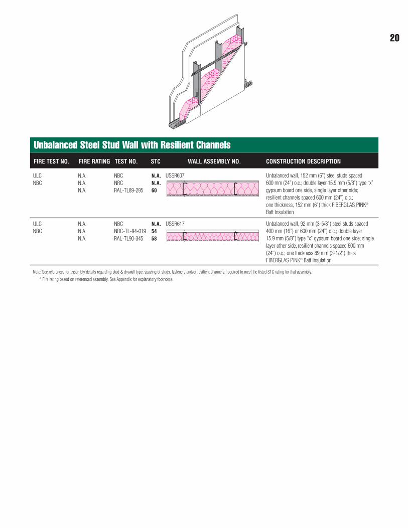
Unbalanced Steel Stud Wall with Resilient ChannelsFIRE TEST NO. FIRE RATING TEST NO. STC WALL ASSEMBLY NO. CONSTRUCTION DESCRIPTION
ULC N.A. NBC N.A.NBC N.A. NRC N.A.
N.A. RAL-TL89-295 60
Unbalanced wall, 152 mm (6”) steel studs spaced 600 mm (24”) o.c.; double layer 15.9 mm (5/8”) type “x”gypsum board one side, single layer other side;resilient channels spaced 600 mm (24”) o.c.; one thickness, 152 mm (6”) thick FIBERGLAS PINK®
Batt Insulation
ULC N.A. NBC N.A.NBC N.A. NRC-TL-94-019 54
N.A. RAL-TL90-345 58
Unbalanced wall, 92 mm (3-5/8”) steel studs spaced400 mm (16”) or 600 mm (24”) o.c.; double layer 15.9 mm (5/8”) type “x” gypsum board one side; singlelayer other side; resilient channels spaced 600 mm(24”) o.c.; one thickness 89 mm (3-1/2”) thickFIBERGLAS PINK® Batt Insulation
USSR607
USSR617
20
21
Note: See references for assembly details regarding stud & drywall type, spacing of studs, fasteners and/or resilient channels, required to meet the listed STC rating for that assembly.
* Fire rating based on referenced assembly. See Appendix for explanatory footnotes.
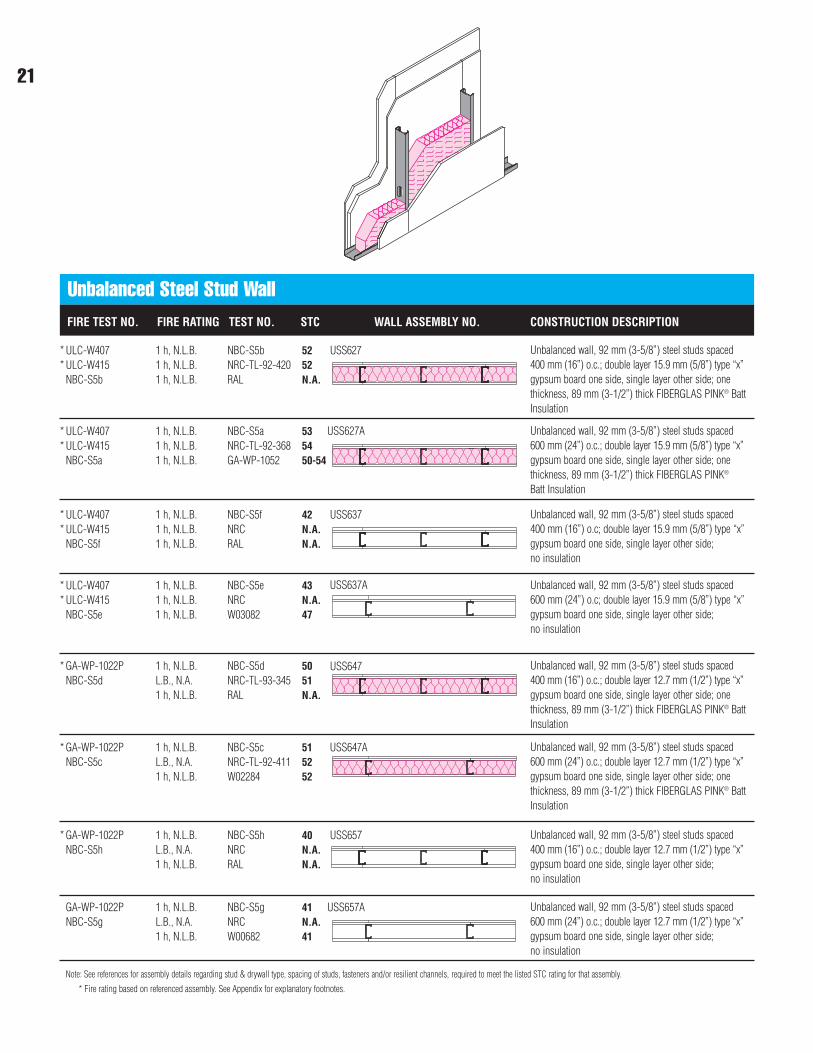
Unbalanced Steel Stud Wall FIRE TEST NO. FIRE RATING TEST NO. STC WALL ASSEMBLY NO. CONSTRUCTION DESCRIPTION
ULC-W407 1 h, N.L.B. NBC-S5b 52ULC-W415 1 h, N.L.B. NRC-TL-92-420 52NBC-S5b 1 h, N.L.B. RAL N.A.
Unbalanced wall, 92 mm (3-5/8”) steel studs spaced400 mm (16”) o.c.; double layer 15.9 mm (5/8”) type “x”gypsum board one side, single layer other side; onethickness, 89 mm (3-1/2”) thick FIBERGLAS PINK® BattInsulation
ULC-W407 1 h, N.L.B. NBC-S5a 53ULC-W415 1 h, N.L.B. NRC-TL-92-368 54NBC-S5a 1 h, N.L.B. GA-WP-1052 50-54
Unbalanced wall, 92 mm (3-5/8”) steel studs spaced600 mm (24”) o.c.; double layer 15.9 mm (5/8”) type “x”gypsum board one side, single layer other side; onethickness, 89 mm (3-1/2”) thick FIBERGLAS PINK®
Batt Insulation
ULC-W407 1 h, N.L.B. NBC-S5f 42ULC-W415 1 h, N.L.B. NRC N.A.NBC-S5f 1 h, N.L.B. RAL N.A.
Unbalanced wall, 92 mm (3-5/8”) steel studs spaced400 mm (16”) o.c; double layer 15.9 mm (5/8”) type “x”gypsum board one side, single layer other side; no insulation
ULC-W407 1 h, N.L.B. NBC-S5e 43ULC-W415 1 h, N.L.B. NRC N.A.NBC-S5e 1 h, N.L.B. W03082 47
Unbalanced wall, 92 mm (3-5/8”) steel studs spaced600 mm (24”) o.c; double layer 15.9 mm (5/8”) type “x”gypsum board one side, single layer other side; no insulation
GA-WP-1022P 1 h, N.L.B. NBC-S5d 50NBC-S5d L.B., N.A. NRC-TL-93-345 51
1 h, N.L.B. RAL N.A.
Unbalanced wall, 92 mm (3-5/8”) steel studs spaced400 mm (16”) o.c.; double layer 12.7 mm (1/2”) type “x”gypsum board one side, single layer other side; onethickness, 89 mm (3-1/2”) thick FIBERGLAS PINK® BattInsulation
GA-WP-1022P 1 h, N.L.B. NBC-S5c 51NBC-S5c L.B., N.A. NRC-TL-92-411 52
1 h, N.L.B. W02284 52
GA-WP-1022P 1 h, N.L.B. NBC-S5h 40NBC-S5h L.B., N.A. NRC N.A.
1 h, N.L.B. RAL N.A.
Unbalanced wall, 92 mm (3-5/8”) steel studs spaced400 mm (16”) o.c.; double layer 12.7 mm (1/2”) type “x”gypsum board one side, single layer other side; no insulation
Unbalanced wall, 92 mm (3-5/8”) steel studs spaced600 mm (24”) o.c.; double layer 12.7 mm (1/2”) type “x”gypsum board one side, single layer other side; onethickness, 89 mm (3-1/2”) thick FIBERGLAS PINK® BattInsulation
USS627
USS627A
USS637
USS637A
USS647
USS647A
USS657
GA-WP-1022P 1 h, N.L.B. NBC-S5g 41NBC-S5g L.B., N.A. NRC N.A.
1 h, N.L.B. W00682 41
Unbalanced wall, 92 mm (3-5/8”) steel studs spaced600 mm (24”) o.c.; double layer 12.7 mm (1/2”) type “x”gypsum board one side, single layer other side; no insulation
USS657A
**
**
**
**
*
*
*
22
Note: See references for assembly details regarding stud & drywall type, spacing of studs, fasteners and/or resilient channels, required to meet the listed STC rating for that assembly.
* Fire rating based on referenced assembly. See Appendix for explanatory footnotes.
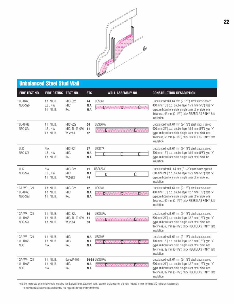
Unbalanced Steel Stud Wall FIRE TEST NO. FIRE RATING TEST NO. STC WALL ASSEMBLY NO. CONSTRUCTION DESCRIPTION
UL-U468 1 h, N.L.B. NBC-S2b 44NBC-S2b L.B., N.A. NRC N.A.
1 h, N.L.B. RAL N.A.
Unbalanced wall, 64 mm (2-1/2”) steel studs spaced400 mm (16”) o.c.; double layer 15.9 mm (5/8”) type “x”gypsum board one side, single layer other side; onethickness, 65 mm (2-1/2”) thick FIBERGLAS PINK® BattInsulation
UL-U468 1 h, N.L.B. NBC-S2a 50NBC-S2a L.B., N.A. NRC-TL-93-036 51
1 h, N.L.B. W02884 52
Unbalanced wall, 64 mm (2-1/2”) steel studs spaced600 mm (24”) o.c.; double layer 15.9 mm (5/8”) type “x”gypsum board one side, single layer other side; onethickness, 65 mm (2-1/2”) thick FIBERGLAS PINK® BattInsulation
ULC N.A. NBC-S2f 37NBC-S2f L.B., N.A. NRC N.A.
1 h, N.L.B. RAL N.A.
Unbalanced wall, 64 mm (2-1/2”) steel studs spaced400 mm (16”) o.c.; double layer 15.9 mm (5/8”) type “x”gypsum board one side, single layer other side; noinsulation
ULC N.A. NBC-S2e 41NBC-S2e L.B., N.A. NRC N.A.
1 h, N.L.B. W05382 44
Unbalanced wall, 64 mm (2-1/2”) steel studs spaced600 mm (24”) o.c.; double layer 15.9 mm (5/8”) type “x”gypsum board one side, single layer other side; noinsulation
GA-WP-1021 1 h, N.L.B. NBC-S2d 42UL-U468 1 h, N.L.B. NRC N.A.NBC-S2d 1 h, N.L.B. RAL N.A.
Unbalanced wall, 64 mm (2-1/2”) steel studs spaced400 mm (16”) o.c.; double layer 12.7 mm (1/2”) type “x”gypsum board one side, single layer other side; onethickness, 65 mm (2-1/2”) thick FIBERGLAS PINK® BattInsulation
GA-WP-1021 1 h, N.L.B. NBC-S2c 50UL-U468 1 h, N.L.B. NRC-TL-93-039 51NBC-S2c 1 h, N.L.B. W02984 50
GA-WP-1021 1 h, N.L.B. NBC N.A.UL-U468 1 h, N.L.B. NRC N.A.NBC N.A. RAL N.A.
Unbalanced wall, 64 mm (2-1/2”) steel studs spaced400 mm (16”) o.c.; double layer 12.7 mm (1/2”) type “x”gypsum board one side, single layer other side; onethickness, 89 mm (3-1/2”) thick FIBERGLAS PINK® BattInsulation
Unbalanced wall, 64 mm (2-1/2”) steel studs spaced600 mm (24”) o.c.; double layer 12.7 mm (1/2”) type “x”gypsum board one side, single layer other side; onethickness, 65 mm (2-1/2”) thick FIBERGLAS PINK® BattInsulation
USS667
USS667A
USS677
USS677A
USS687
USS687A
USS697
GA-WP-1021 1 h, N.L.B. GA-WP-1021 50-54UL-U468 1 h, N.L.B. NRC N.A.NBC N.A. RAL N.A.
Unbalanced wall, 64 mm (2-1/2”) steel studs spaced600 mm (24”) o.c.; double layer 12.7 mm (1/2”) type “x”gypsum board one side, single layer other side; onethickness, 89 mm (3-1/2”) thick FIBERGLAS PINK® BattInsulation
USS697A
*
*
**
**
**
**
Note: See references for assembly details regarding stud & drywall type, spacing of studs, fasteners and/or resilient channels, required to meet the listed STC rating for that assembly.
* Fire rating based on referenced assembly. See Appendix for explanatory footnotes.
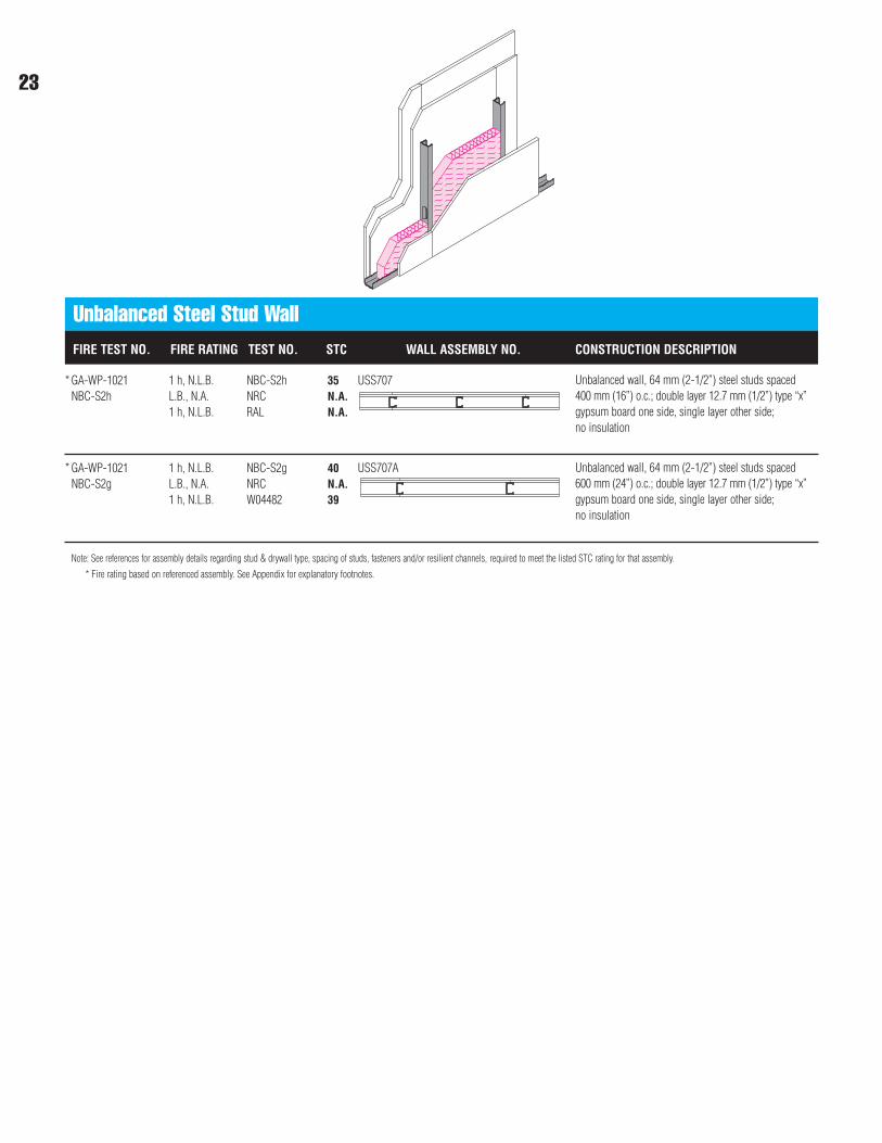
Unbalanced Steel Stud Wall FIRE TEST NO. FIRE RATING TEST NO. STC WALL ASSEMBLY NO. CONSTRUCTION DESCRIPTION
GA-WP-1021 1 h, N.L.B. NBC-S2h 35NBC-S2h L.B., N.A. NRC N.A.
1 h, N.L.B. RAL N.A.
Unbalanced wall, 64 mm (2-1/2”) steel studs spaced400 mm (16”) o.c.; double layer 12.7 mm (1/2”) type “x”gypsum board one side, single layer other side; no insulation
GA-WP-1021 1 h, N.L.B. NBC-S2g 40NBC-S2g L.B., N.A. NRC N.A.
1 h, N.L.B. W04482 39
Unbalanced wall, 64 mm (2-1/2”) steel studs spaced600 mm (24”) o.c.; double layer 12.7 mm (1/2”) type “x”gypsum board one side, single layer other side; no insulation
USS707
USS707A
*
*
23
������������������������������������������������������������������������������������������������������������������������������������������������
@@@@@@@@@@@@@@@@@@@@@@@@@@@@@@@@@@@@@@@@@@@@@@@@@@@@@@@@@@@@@@@@@@@@@@@@@@@@@@@@@@@@@@@@@@@@@@@@@@@@@@@@@@@@@@@@@@@@@@@@@@@@@@@@@@@@@@@@@@@@@@@@
������������������������������������������������������������������������������������������������������������������������������������������������
ÀÀÀÀÀÀÀÀÀÀÀÀÀÀÀÀÀÀÀÀÀÀÀÀÀÀÀÀÀÀÀÀÀÀÀÀÀÀÀÀÀÀÀÀÀÀÀÀÀÀÀÀÀÀÀÀÀÀÀÀÀÀÀÀÀÀÀÀÀÀÀÀÀÀÀÀÀÀÀÀÀÀÀÀÀÀÀÀÀÀÀÀÀÀÀÀÀÀÀÀÀÀÀÀÀÀÀÀÀÀÀÀÀÀÀÀÀÀÀÀÀÀÀÀÀÀÀÀÀÀÀÀÀÀÀÀÀÀÀÀÀÀÀÀ
�@�����@@@@����ÀÀÀÀ
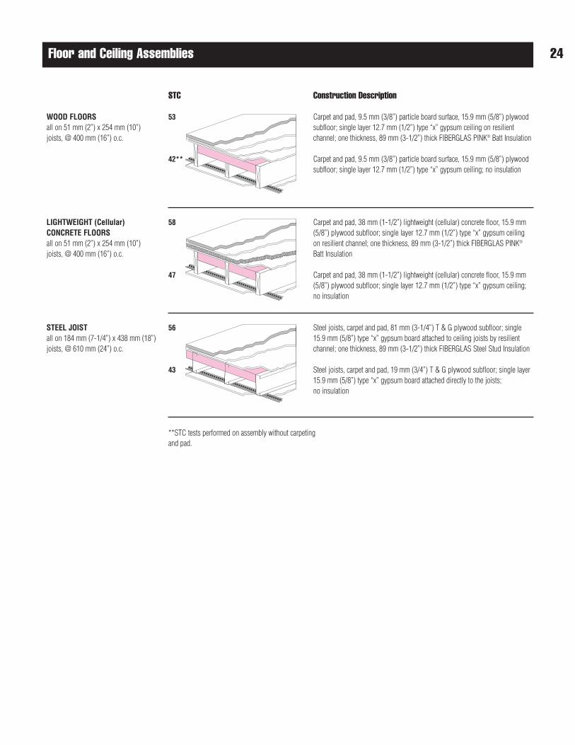
Floor and Ceiling Assemblies
Construction Description
Carpet and pad, 9.5 mm (3/8”) particle board surface, 15.9 mm (5/8”) plywoodsubfloor; single layer 12.7 mm (1/2”) type “x” gypsum ceiling on resilientchannel; one thickness, 89 mm (3-1/2”) thick FIBERGLAS PINK® Batt Insulation
Carpet and pad, 9.5 mm (3/8”) particle board surface, 15.9 mm (5/8”) plywoodsubfloor; single layer 12.7 mm (1/2”) type “x” gypsum ceiling; no insulation
Carpet and pad, 38 mm (1-1/2”) lightweight (cellular) concrete floor, 15.9 mm(5/8”) plywood subfloor; single layer 12.7 mm (1/2”) type “x” gypsum ceilingon resilient channel; one thickness, 89 mm (3-1/2”) thick FIBERGLAS PINK®
Batt Insulation
Carpet and pad, 38 mm (1-1/2”) lightweight (cellular) concrete floor, 15.9 mm(5/8”) plywood subfloor; single layer 12.7 mm (1/2”) type “x” gypsum ceiling;no insulation
Steel joists, carpet and pad, 81 mm (3-1/4”) T & G plywood subfloor; single15.9 mm (5/8”) type “x” gypsum board attached to ceiling joists by resilientchannel; one thickness, 89 mm (3-1/2”) thick FIBERGLAS Steel Stud Insulation
Steel joists, carpet and pad, 19 mm (3/4”) T & G plywood subfloor; single layer15.9 mm (5/8”) type “x” gypsum board attached directly to the joists; no insulation
STC
53
42**
58
47
56
43
**STC tests performed on assembly without carpetingand pad.
WOOD FLOORSall on 51 mm (2”) x 254 mm (10”)joists, @ 400 mm (16”) o.c.
LIGHTWEIGHT (Cellular)CONCRETE FLOORS all on 51 mm (2”) x 254 mm (10”)joists, @ 400 mm (16”) o.c.
STEEL JOIST all on 184 mm (7-1/4”) x 438 mm (18”)joists, @ 610 mm (24”) o.c.
24
Sound Absorption Coefficients
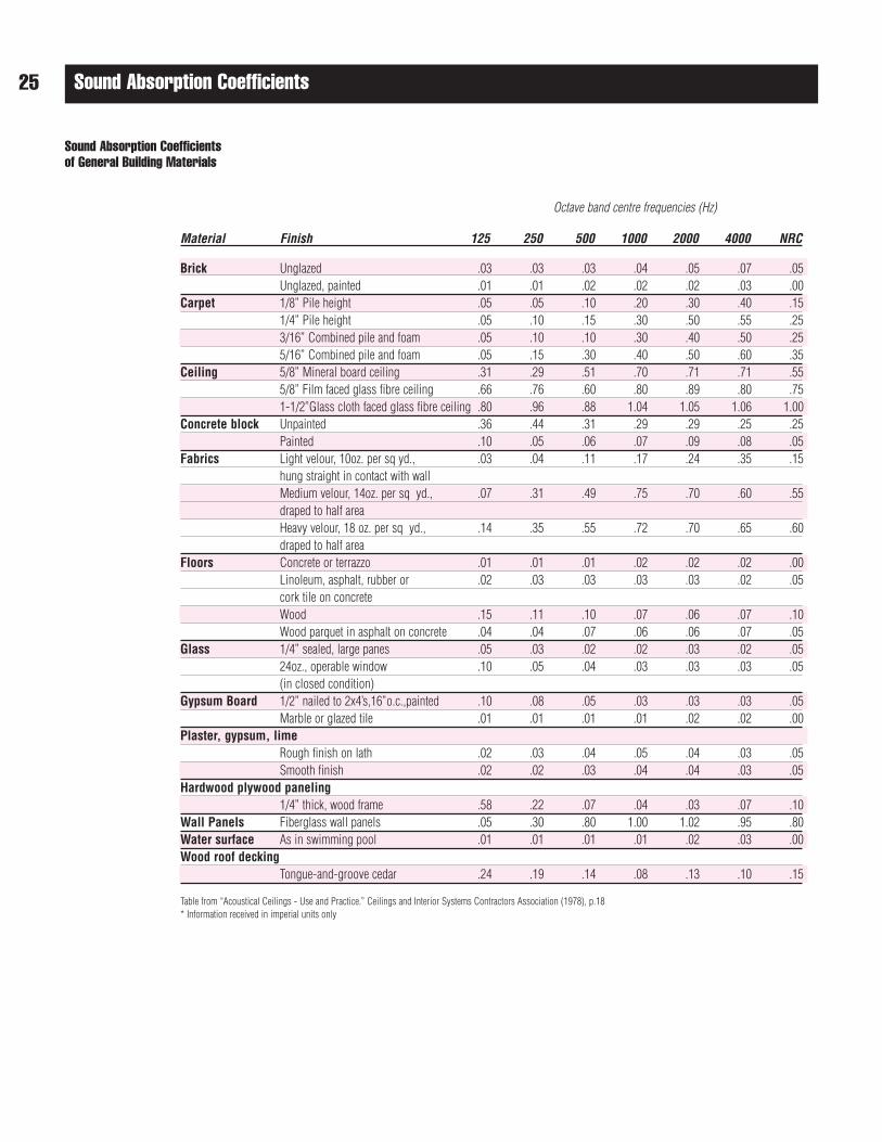
Sound Absorption Coefficients of General Building Materials
Table from “Acoustical Ceilings - Use and Practice.” Ceilings and Interior Systems Contractors Association (1978), p.18* Information received in imperial units only
25
Octave band centre frequencies (Hz)
Material Finish 125 250 500 1000 2000 4000 NRC
Brick Unglazed .03 .03 .03 .04 .05 .07 .05Unglazed, painted .01 .01 .02 .02 .02 .03 .00
Carpet 1/8” Pile height .05 .05 .10 .20 .30 .40 .15 1/4” Pile height .05 .10 .15 .30 .50 .55 .253/16” Combined pile and foam .05 .10 .10 .30 .40 .50 .255/16” Combined pile and foam .05 .15 .30 .40 .50 .60 .35
Ceiling 5/8” Mineral board ceiling .31 .29 .51 .70 .71 .71 .555/8” Film faced glass fibre ceiling .66 .76 .60 .80 .89 .80 .751-1/2”Glass cloth faced glass fibre ceiling .80 .96 .88 1.04 1.05 1.06 1.00
Concrete block Unpainted .36 .44 .31 .29 .29 .25 .25Painted .10 .05 .06 .07 .09 .08 .05
Fabrics Light velour, 10oz. per sq yd., .03 .04 .11 .17 .24 .35 .15hung straight in contact with wall Medium velour, 14oz. per sq yd., .07 .31 .49 .75 .70 .60 .55draped to half areaHeavy velour, 18 oz. per sq yd., .14 .35 .55 .72 .70 .65 .60draped to half area
Floors Concrete or terrazzo .01 .01 .01 .02 .02 .02 .00Linoleum, asphalt, rubber or .02 .03 .03 .03 .03 .02 .05cork tile on concreteWood .15 .11 .10 .07 .06 .07 .10Wood parquet in asphalt on concrete .04 .04 .07 .06 .06 .07 .05
Glass 1/4” sealed, large panes .05 .03 .02 .02 .03 .02 .0524oz., operable window .10 .05 .04 .03 .03 .03 .05(in closed condition)
Gypsum Board 1/2” nailed to 2x4’s,16”o.c.,painted .10 .08 .05 .03 .03 .03 .05Marble or glazed tile .01 .01 .01 .01 .02 .02 .00
Plaster, gypsum, limeRough finish on lath .02 .03 .04 .05 .04 .03 .05Smooth finish .02 .02 .03 .04 .04 .03 .05
Hardwood plywood paneling1/4” thick, wood frame .58 .22 .07 .04 .03 .07 .10
Wall Panels Fiberglass wall panels .05 .30 .80 1.00 1.02 .95 .80Water surface As in swimming pool .01 .01 .01 .01 .02 .03 .00Wood roof decking
Tongue-and-groove cedar .24 .19 .14 .08 .13 .10 .15
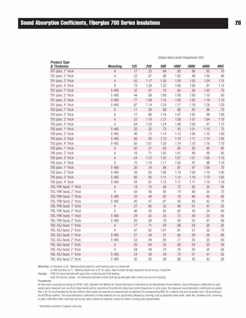
Sound Absorption Coefficients, Fiberglas 700 Series Insulations
Mounting: •A (formerly no.4) - Material placed against a solid backing such as a block wall•E-405 (formerly no.7) - Material placed over a 16” air space. Data includes facings exposed to sound source, if specified
Facings: •FRK-foil-faced laminate with glass fiber reinforcing and Kraft backing•ASJ (All-Service Jacket) - An embossed laminate of white Kraft facing with glass fiber reinforcing and a foil backing
Procedures:All tests were conducted according to ASTM C 423, Standard Test Method for Sound Absorption Coefficients by the Reverberation Room Method. Sound Absorption coefficients for eachsample were measured over one-third octave bands and are reported at the preferred octave band center frequencies.In some cases, the measured sound absorption coefficients are greaterthan 1.00. As recommended by the test method, these values are reported as measured and not adjusted.The corresponding NRC for a material may also be greater than 1.00 according tothe ASTM test method. The sound absorption coefficients of these materials are not significantly affected by coverings such as expanded sheet metal, metal lath, hardware cloth, screeningor glass cloth.When other coverings having less open surfaces are required, consult an Owens Corning sales representative.
* Information received in imperial units only
26
Octave band centre frequencies (Hz)Product Type& Thickness Mounting 125 250 500 1000 2000 4000 NRC701 plain, 1” thick A .17 .33 .64 .83 .90 .92 .70701 plain, 2” thick A .22 .67 .98 1.02 .98 1.00 .90701 plain, 3” thick A .43 1.17 1.26 1.09 1.03 1.04 1.15701 plain, 4” thick A .73 1.29 1.22 1.06 1.00 .97 1.15701 plain, 1” thick E-405 .32 .41 .70 .83 .93 1.02 .70701 plain, 2” thick E-405 .44 .68 1.00 1.09 1.06 1.10 .95701 plain, 3” thick E-405 .77 1.08 1.16 1.09 1.05 1.18 1.10 701 plain, 4” thick E-405 .87 1.14 1.24 1.17 1.18 1.28 1.20703 plain, 1” thick A .11 .28 .68 .90 .93 .96 .70703 plain, 2” thick A .17 .86 1.14 1.07 1.02 .98 1.00703 plain, 3” thick A .53 1.19 1.21 1.08 1.01 1.04 1.10703 plain, 4” thick A .84 1.24 1.24 1.08 1.00 .97 1.15703 plain, 1” thick E-405 .32 .32 .73 .93 1.01 1.10 .75703 plain, 2” thick E-405 .40 .73 1.14 1.13 1.06 1.10 1.00703 plain, 3” thick E-405 .66 .93 1.13 1.10 1.11 1.14 1.05703 plain, 4” thick E-405 .65 1.01 1.20 1.14 1.10 1.16 1.10705 plain, 1” thick A .02 .27 .63 .85 .93 .95 .65705 plain, 2” thick A .16 .71 1.02 1.01 .99 .99 .95705 plain, 3” thick A .54 1.12 1.23 1.07 1.01 1.05 1.10705 plain, 4” thick A .75 1.19 1.17 1.05 .97 .98 1.10705 plain, 1” thick E-405 .30 .34 .68 .87 .97 1.06 .70705 plain, 2” thick E-405 .39 .63 1.06 1.13 1.09 1.10 1.00705 plain, 3” thick E-405 .66 .92 1.11 1.12 1.10 1.19 1.05705 plain, 4” thick E-405 .59 .91 1.15 1.11 1.11 1.19 1.10703, FRK faced, 1” thick A .18 .75 .58 .72 .62 .35 .65703, FRK faced, 2” thick A .63 .56 .95 .74 .60 .35 .75703, FRK faced, 1” thick E-405 .33 .49 .62 .78 .66 .45 .65703, FRK faced, 2” thick E-405 .45 .47 .97 .93 .65 .42 .75705, FRK faced, 1” thick A .27 .66 .33 .66 .51 .41 .55705, FRK faced, 2” thick A .60 .50 .63 .82 .45 .34 .60705, FRK faced, 1” thick E-405 .29 .52 .33 .72 .58 .53 .55705, FRK faced, 2” thick E-405 .50 .36 .70 .90 .52 .47 .60703, ASJ faced, 1” thick A .17 .71 .59 .68 .54 .30 .65703, ASJ faced, 2” thick A .47 .62 1.01 .81 .51 .32 .75703, ASJ faced, 1” thick E-405 .27 .54 .57 .66 .58 .36 .60703, ASJ faced, 2” thick E-405 .53 .44 .93 .77 .55 .35 .65705, ASJ faced, 1” thick A .20 .64 .33 .56 .54 .33 .50705, ASJ faced, 2” thick A .58 .49 .73 .76 .55 .35 .65705, ASJ faced, 1” thick E-405 .24 .58 .29 .75 .57 .41 .55705, ASJ faced, 2” thick E-405 .42 .35 .69 .80 .55 .42 .60
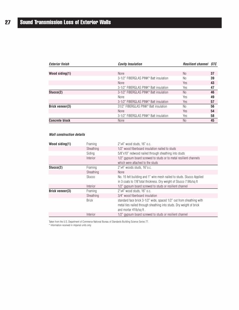
Sound Transmission Loss of Exterior Walls27
Exterior finish Cavity Insulation Resilient channel STC
Wood siding(1) None No 373-1/2” FIBERGLAS PINK® Batt insulation No 39None Yes 433-1/2” FIBERGLAS PINK® Batt insulation Yes 47
Stucco(2) 3-1/2” FIBERGLAS PINK® Batt insulation No 46None Yes 493-1/2” FIBERGLAS PINK® Batt insulation Yes 57
Brick veneer(3) 31/2” FIBERGLAS PINK® Batt insulation No 56None Yes 543-1/2” FIBERGLAS PINK® Batt insulation Yes 58
Concrete block None No 45
Wall construction details
Wood siding(1) Framing 2”x4” wood studs, 16” o.c.Sheathing 1/2” wood fiberboard insulation nailed to studsSiding 5/8”x10” redwood nailed through sheathing into studsInterior 1/2” gypsum board screwed to studs or to metal resilient channels
which were attached to the studsStucco(2) Framing 2”x4” woods studs, 16”o.c.
Sheathing NoneStucco No. 15 felt building and 1” wire mesh nailed to studs. Stucco Applied
in 3 coats to 7/8”total thickness. Dry weight of Stucco 7.9lb/sq ft Interior 1/2” gypsum board screwed to studs or resilient channel
Brick veneer(3) Framing 2”x4” wood studs, 16” o.c.Sheathing 3/4” wood fiberboard insulationBrick standard face brick 3-1/2” wide, spaced 1/2” out from sheathing with
metal ties nailed through sheathing into studs. Dry weight of brick and mortar 41lb/sq ft .
Interior 1/2” gypsum board screwed to studs or resilient channel
Taken from the U.S. Department of Commerce National Bureau of Standards Building Science Series 77.* Information received in imperial units only
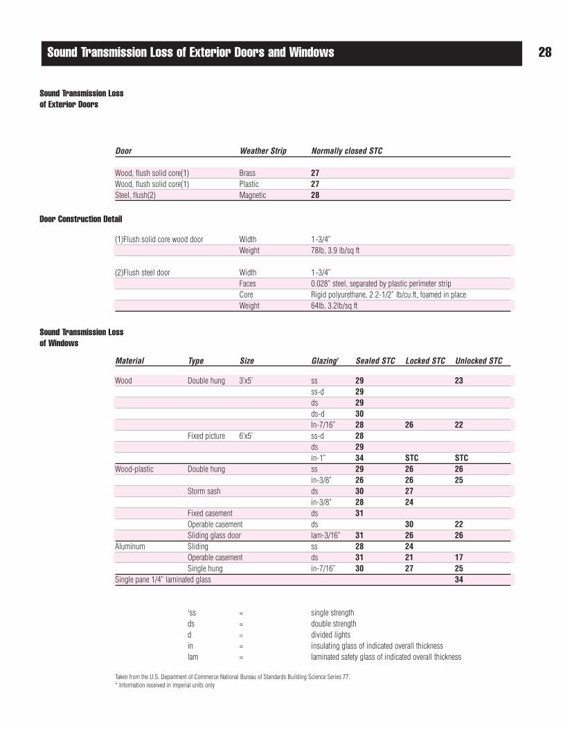
28Sound Transmission Loss of Exterior Doors and Windows
Sound Transmission Loss of Exterior Doors
Door Construction Detail
Sound Transmission Loss of Windows
Door Weather Strip Normally closed STC
Wood, flush solid core(1) Brass 27Wood, flush solid core(1) Plastic 27Steel, flush(2) Magnetic 28
(1)Flush solid core wood door Width 1-3/4”Weight 78lb, 3.9 lb/sq ft
(2)Flush steel door Width 1-3/4”Faces 0.028” steel, separated by plastic perimeter stripCore Rigid polyurethane, 2 2-1/2” lb/cu.ft, foamed in placeWeight 64lb, 3.2lb/sq ft
Material Type Size Glazing1 Sealed STC Locked STC Unlocked STC
Wood Double hung 3’x5’ ss 29 23ss-d 29ds 29ds-d 30In-7/16” 28 26 22
Fixed picture 6’x5’ ss-d 28ds 29in-1” 34 STC STC
Wood-plastic Double hung ss 29 26 26in-3/8” 26 26 25
Storm sash ds 30 27in-3/8” 28 24
Fixed casement ds 31Operable casement ds 30 22Sliding glass door lam-3/16” 31 26 26
Aluminum Sliding ss 28 24Operable casement ds 31 21 17Single hung in-7/16” 30 27 25
Single pane 1/4” laminated glass 34
1ss = single strengthds = double strengthd = divided lightsin = insulating glass of indicated overall thicknesslam = laminated safety glass of indicated overall thickness
Taken from the U.S. Department of Commerce National Bureau of Standards Building Science Series 77.* Information received in imperial units only
29 Appendix
*GA File No. WP-1021, non load-bearing steel stud stud wall assembly, listed in The Gypsum Association Fire Resistance Design Manual GA-600-97, documents a 1 hour fire rating using 64 mm (2-1/2”) steel studs, 0.46 mm (25 Gauge), spaced 600 mm (24”) o.c. with a single layer of 12.7 mm (1/2”) type “x” gypsum wallboardon one side, double layer other side, and no insulation. Item 10 Under the General Explanatory Notes section of this manual, page 3, states that “When not specified asa component of a fire tested wall or partition system, mineral or glass fiber insulation of a thickness not exceeding that of the stud depth shall be permitted to be addedwithin the stud cavity”. Item 13 states that “Greater stud sizes (depths) shall be permitted to be used in metal or wood stud systems. Metal studs of heavier gauge thanthose tested shall be permitted. The assigned rating of any load-bearing system shall also apply to the same system when used as a non load-bearing system.Indicated stud spacings are maximums”. Item 18 states that “Additional layers of the type “x” or regular gypsum board shall be permitted to be added to any system”.The batts enhance the acoustical performance of the assembly without affecting the listed fire rating.
*GA File No. WP-1022P, non load-bearing steel stud stud wall assembly, listed in The Gypsum Association Fire Resistance Design Manual GA-600-97, documents a 1 hour fire rating using 64 mm (2-1/2”) steel studs, 0.46 mm (25 Gauge), spaced 600 mm (24”) o.c. with a double layer of 12.7 mm (1/2”) proprietary type “x”gypsum wallboard (Gold Bond Fire-Shield G) on one side, single layer other side and no insulation. Item 10 Under the General Explanatory Notes section of thismanual, page 3, states that “When not specified as a component of a fire tested wall or partition system, mineral or glass fiber insulation of a thickness not exceedingthat of the stud depth shall be permitted to be added within the stud cavity”. Item 13 states that “Greater stud sizes (depths) shall be permitted to be used in metal orwood stud systems. Metal studs of heavier gauge than those tested shall be permitted. The assigned rating of any load-bearing system shall also apply to the samesystem when used as a non load-bearing system. Indicated stud spacings are maximums”. Item 18 states that “Additional layers of the type “x” or regular gypsumboard shall be permitted to be added to any system”. Only the specified proprietary type gypsum board listed in the assembly description can be used to meet thelisted rating. The batts enhance the acoustical performance of the assembly without affecting the listed fire rating.
*GA File No. WP-1521, non load-bearing steel stud stud wall assembly, listed in The Gypsum Association Fire Resistance Design Manual GA-600-97, documents a 2 hour fire rating using 92 mm (3-5/8”) steel studs, 0.46 mm (25 Gauge), spaced 600 mm (24”) o.c. with a double layer of 12.7 mm (1/2”) type “x” gypsumwallboard on each side and no insulation. Item 10 Under the General Explanatory Notes section of this manual, page 3, states that “When not specified as acomponent of a fire tested wall or partition system, mineral or glass fiber insulation of a thickness not exceeding that of the stud depth shall be permitted to be addedwithin the stud cavity”. Item 13 states that “Greater stud sizes (depths) shall be permitted to be used in metal-or wood-stud systems. Metal studs of heavier gauge thanthose tested shall be permitted. The assigned rating of any load-bearing system shall also apply to the same system when used as a non load-bearing system.Indicated stud spacings are maximums”. Item 18 states that “Additional layers of the type “x” or regular gypsum board shall be permitted to be added to any system”.The batts enhance the acoustical performance of the assembly without affecting the listed fire rating.
*GA File No. WP-1615, non load-bearing steel stud stud wall assembly, listed in The Gypsum Association Fire Resistance Design Manual GA-600-97, documents a 2 hour fire rating using 64 mm (2-1/2”) steel studs, 0.46 mm (25 Gauge), spaced 600 mm (24”) o.c. with a double layer of 12.7 mm (1/2”) type “x” gypsumwallboard on each side and no insulation. Item 10 Under the General Explanatory Notes section of this manual, page 3, states that “When not specified as acomponent of a fire tested wall or partition system, mineral or glass fiber insulation of a thickness not exceeding that of the stud depth shall be permitted to be addedwithin the stud cavity”. Item 13 states that “Greater stud sizes (depths) shall be permitted to be used in metal-or wood-stud systems. Metal studs of heavier gauge thanthose tested shall be Permitted. The assigned rating of any load-bearing system shall also apply to the same system when used as a non load-bearing system.Indicated stud spacings are maximums”. Item 18 states that “Additional layers of the type “x” or regular gypsum board shall be permitted to be added to any system”.The batts enhance the acoustical performance of the assembly without affecting the listed fire rating.
*GA File No. WP-1711, non load-bearing steel stud stud wall assembly, listed in The Gypsum Association Fire Resistance Design Manual GA-600-97, documents a 2 hour fire rating using 92 mm (3-5/8”) steel studs, 0.46 mm (25 Gauge), spaced 600 mm (24”) o.c. with a double layer of 15.9 mm (5/8”) type “x” gypsumwallboard on each side and no insulation. Item 10 Under the General Explanatory Notes section of this manual, page 3, states that “When not specified as acomponent of a fire tested wall or partition system, mineral or glass fiber insulation of a thickness not exceeding that of the stud depth shall be permitted to be addedwithin the stud cavity”. Item 13 states that “Greater stud sizes (depths) shall be permitted to be used in metal or wood stud systems. Metal studs of heavier gauge thanthose tested shall be permitted. The assigned rating of any load-bearing system shall also apply to the same system when used as a non load-bearing system.Indicated stud spacings are maximums”. Item 18 states that “Additional layers of the type “x” or regular gypsum board shall be permitted to be added to any system”.The batts enhance the acoustical performance of the assembly without affecting the listed fire rating.
*GA File No. WP-3370, load-bearing double wood stud wall assembly, listed in The Gypsum Association Fire Resistance Design Manual GA-600-97, documents a 1 hour fire rating using a double row of 38x89 mm (2”x4”) wood studs spaced 400 mm (16”) o.c. on separate plates 25 mm (1”) apart and a single layer of 15.9 mm(5/8”) type “x” gypsum wallboard on each side and no insulation. Item 10 Under the General Explanatory Notes section of this manual, page 3, states that “When notspecified as a component of a fire tested wall or partition system, mineral or glass fiber insulation of a thickness not exceeding that of the stud depth shall be permittedto be added within the stud cavity”. Item 13 states that “greater stud sizes (depths) shall be permitted to be used in metal-or wood-stud systems. Metal studs of heaviergauge than those tested shall be permitted. The assigned rating of any load-bearing system shall also apply to the same system when used as a non load-bearingsystem. Indicated stud spacings are maximums”. Item 18 states that “Additional layers of the type “x” or regular gypsum board shall be permitted to be added to anysystem”. The batts enhance the acoustical performance of the assembly without affecting the listed fire rating.
*GA File No. WP-5015, non load-bearing chase wall assembly, listed in The Gypsum Association Fire Resistance Design Manual GA-600-97, documents a 1 hour firerating using a double row of 41 mm (1-5/8”) steel studs, 0.46 mm (25 Gauge), spaced 600 mm (24”) o.c. and 156 mm (6-1/4”) apart, with a single layer of 15.9 mm(5/8”) type “x” gypsum wallboard on each side and no insulation. Item 10 Under the General Explanatory Notes section of this manual, page 3, states that “When notspecified as a component of a fire tested wall or partition system, mineral or glass fiber insulation of a thickness not exceeding that of the stud depth shall be permittedto be added within the stud cavity”. Item 13 states that “Greater stud sizes (depths) shall be permitted to be used in metal-or wood-stud systems. Metal studs of heaviergauge than those tested shall be permitted. The assigned rating of any load-bearing system shall also apply to the same system when used as a non load-bearingsystem. Indicated stud spacings are maximums”. Item 18 states that “Additional layers of the type “x” or regular gypsum board shall be permitted to be added to anysystem”. The batts enhance the acoustical performance of the assembly without affecting the listed fire rating.
*GA File No. WP-5105, non load-bearing chase wall assembly, listed in The Gypsum Association Fire Resistance Design Manual GA-600-97, documents a 2 hour firerating using a double row of 41 mm (1-5/8”) steel studs, 0.46 mm (25 Gauge), spaced 600 mm (24”) o.c. and 156 mm (6-1/4”) apart, with a double layer of 15.9 mm(5/8”) type “x” gypsum wallboard on each side and no insulation. Item 10 Under the General Explanatory Notes section of this manual, page 3, states that “When notspecified as a component of a fire tested wall or partition system, mineral or glass fiber insulation of a thickness not exceeding that of the stud depth shall be permittedto be added within the stud cavity”. Item 13 states that “Greater stud sizes (depths) shall be permitted to be used in metal-or wood-stud systems. Metal studs of heaviergauge than those tested shall be permitted. The assigned rating of any load-bearing system shall also apply to the same system when used as a non load-bearingsystem. Indicated stud spacings are maximums”. Item 18 states that “Additional layers of the type “x” or regular gypsum board shall be permitted to be added to anysystem”. The batts enhance the acoustical performance of the assembly without affecting the listed fire rating.
*OSUT-3127, load-bearing wall assembly uses 38x89 mm (2”x4”) wood studs spaced 400 mm (16”) o.c. max. with resilient channels, a single layer of 15.9 mm (5/8”)type “x” gypsum board on each side and 38 mm (1-1/2”) FIBERGLAS PINK® Batt Insulation, yielding a 1 hour fire rating. See “Summarization of Test Results” reportof Project T-3127 conducted at the Engineering Experiment Station at Ohio State University. Under standard engineering practices, substituting the single layer of 15.9 mm (5/8”) drywall, with two layers of 12.7 mm (1/2”) drywall, and adding extra insulation, will not affect the listed fire rating.
*ULC-W301, load-bearing wall assembly listed in ULC List of Equipment & Materials Volume III, Fire Resistance Ratings, documents a 1 hour fire rating using 38x89 mm (2”x4”) wood studs spaced 400 mm (16”) o.c. with a single layer of 15.9 mm (5/8”) type “x” gypsum board (Atlantic/Canadian/Domtar/GeorgiaPacific/Westroc) on each side and no insulation. On Page 19 of Volume III, under Walls and Partitions, it is stated that “With the exception of support (i.e. studs) andfastener (i.e. nails, screws) spacings, the dimensions given in the following designs are to be construed as the minimum allowable for each rated assembly. Supportand fastener spacings are the maximum allowable. Mineral fiber thermal building insulation that is processed from rock, slag and glass only may be used inassemblies consisting of wallboard and steel or wood studs when illustrated without insulation, without detracting from the rating assigned to the assembly”. SeeOwens Corning Canada’s Batts & Blankets listing under Guide No. 40 U8.3 of Volume II. The batts enhance the acoustical performance of the assembly withoutaffecting the listed fire rating.
*ULC-W302, load- bearing wall assembly listed in ULC List of Equipment & Materials Volume III, Fire Resistance Ratings, documents a 45 minute fire rating using38x89 mm (2”x4”) wood studs spaced 400 mm (16”) o.c. with a single layer of 12.7 mm (1/2”) type “x” gypsum board (Atlantic/Canadian/Domtar/GeorgiaPacific/Westroc) on each side and no insulation. On page 19 of Volume III, under Walls and Partitions, it is stated that “With the exception of support (i.e. studs) andfastener (i.e. nails, screws) spacings, the dimensions given in the following designs are to be construed as the minimum allowable for each rated assembly. Supportand fastener spacings are the maximum allowable. Mineral fiber thermal building insulation that is processed from rock, slag and glass only may be used inassemblies consisting of wall board and steel or wood studs when illustrated without insulation, without detracting from the rating assigned to the assembly”. SeeOwens Corning Canada’s Batts & Blankets listing under Guide No. 40 U8.3 of Volume II. The batts enhance the acoustical performance of the assembly withoutaffecting the listed fire rating.
*ULC-W406, non load-bearing wall assembly listed in ULC List of Equipment and Materials, Volume III, Fire resistance Ratings, documents a 2 hour fire rating using64 mm (2-1/2”) steel studs, 0.5 mm (25 Gauge), spaced 600 mm (24”) o.c. with a double layer of 12,7 mm (1/2”) type”x” gypsum board (Canadian Gypsum) onboth sides and no insulation. On page 19 of Volume III, under Walls and partitions, it is stated that “With the exception of support (i.e. studs) and fastener (i.e. nails,screws) spacings, the dimensions given in the following designs are to be construed as the minimum allowable for each rated assembly. Support and fastenerspacings are the maximum allowable. Mineral fibre thermal building insulation that is processed from rock, slag and glass only may be used in assembliesconsisting of wallboard and steel or wood studs when illustrated without insulation, without detracting from the rating assigned to the assembly.” See OwensCorning Canada’s Batts & Blankets listing under Guide No. 40 U8.3 of Volume II. The batts enhance the acoustical performance of the assembly without affecting thelisted fire rating.
*ULC-W407, non load-bearing wall assembly listed in ULC List of Equipment & Materials Volume III, Fire Resistance Ratings, documents a 1 hour fire rating using 92 mm (3-5/8”) steel studs, 0.46 mm (25 Gauge), spaced 600 mm (24”) o.c. with a single layer of 15.9 mm (5/8”) type “x” gypsum board (Canadian Gypsum) oneach side and no insulation. On page 19 of Volume III, under Walls and Partitions, it is stated that “With the exception of support (i.e. studs) and fastener (i.e. nails,screws) spacings, the dimensions given in the following designs are to be construed as the minimum allowable for each rated assembly. Support and fastenerspacings are the maximum allowable. Mineral fiber thermal building insulation that is processed from rock, slag and glass only may be used in assemblies consistingof wallboard and steel or wood studs when illustrated without insulation, without detracting from the rating assigned to the assembly”. See Owens Corning Canada’sBatts & Blankets listing under Guide No. 40 U8.3 of Volume II. The batts enhance the acoustical performance of the assembly without affecting the listed fire rating.
Appendix 30
*ULC-W414, non load-bearing wall assembly listed in ULC List of Equipment and Materials, Volume III, Fire resistance Ratings, documents a 2 hour fire rating using 63 mm (2-1/2”) steel studs, 0.6 mm (25 Gauge), spaced 600 mm (24”) o.c. with a double layer of 12,7 mm (1/2”) type”x” gypsum board (Atlantic Gypsum, Domtar,Westroc Industries) on both sides and no insulation. On page 19 of Volume III, under Walls and Partitions, it is stated that “With the exception of support (i.e. studs)and fastener (i.e. nails, screws) spacings, the dimensions given in the following designs are to be construed as the minimum allowable for each rated assembly.Support and fastener spacings are the maximum allowable. Mineral fibre thermal building insulation that is processed from rock, slag and glass only may be used inassemblies consisting of wallboard and steel or wood studs when illustrated without insulation, without detracting from the rating assigned to the assembly.” SeeOwens Corning Canada’s Batts & Blankets listing under Guide No. 40 U8.3 of Volume II. The batts enhance the acoustical performance of the assembly withoutaffecting the listed fire rating.
*ULC-W415, non load-bearing wall assembly listed in ULC List of Equipment & Materials Volume III, Fire Resistance Ratings, documents a 1 hour fire rating using 92 mm (3-5/8”) steel studs, 0.46 mm (25 Gauge), spaced 600 mm (24”) o.c. with a single layer of 15.9 mm (5/8”) type “x” gypsum board (Atlantic/Domtar/Westroc)on each side and no insulation. On page 19 of Volume III, under Walls and Partitions it is stated that ”With the exception of support (i.e. studs) and fastener (i.e. nails,screws) spacings, the dimensions given in the following designs are to be construed as the minimum allowable for each rated assembly. Support and fastenerspacings are the maximum allowable. Mineral fiber thermal building insulation that is processed from rock, slag and glass only may be used in assemblies consistingof wallboard and steel or wood studs when illustrated without insulation, without detracting from the rating assigned to the assembly”. See Owens Corning Canada’sBatts & Blankets listing under Guide No. 40 U8.3 of Volume II. The batts enhance the acoustical performance of the assembly without affecting the listed fire rating.
*UL-U305, load-bearing wall assembly listed in Underwriters Laboratories Inc. (ULI) Fire Resistance Directory 1997, Vol.1 documents a 1 hour fire rating using 38x89mm (2”x4”) wood studs (fire stopped) spaced 400 mm (16”) o.c. with a single layer of 15.9 mm (5/8”) type “x” gypsum board on each side (see design description forallowable types) and no insulation. On page 13, under Wall and Partition Assemblies, it is stated that “The hourly rating of a load-bearing assembly also applies to thesame assembly when it is used as a non-load bearing assembly.The size of studs are minimum unless otherwise stated in a design. The spacing of studs is amaximum unless otherwise stated in a design. The use of glass fiber insulation is optional.” The batts enhance the acoustical performance of the assembly withoutaffecting the listed fire rating. See Owens Corning Fiberglas Corp, Batts & Blankets listing, Nos. R13926(N) & R3576(N), under BZJZ.
*UL-U309, load-bearing wall assembly listed in Underwriters Laboratory Inc. (ULI) Fire Resistance Directory 1997, Vol.1 documents a 1 hour fire rating using 38x89 mm(2”x4”) wood studs (fire stopped) spaced 600 mm (24”) o.c. with a single layer of 15.9 mm (5/8”) type “x” gypsum board on each side (see design description forallowable types) and no insulation. On page 13, under Wall and Partition Assemblies, it is stated that “The hourly rating of a load-bearing assembly also applies to thesame assembly when it is used as a non-load bearing assembly. The size of studs are minimum unless otherwise stated in a design. The spacing of studs is amaximum unless otherwise stated in a design. The use of glass fiber insulation is optional.” The batts enhance the acoustical performance of the assembly withoutaffecting the listed fire rating. See Owens Corning Fiberglas Corp, Batts & Blankets listing, Nos. R13926(N) & R3576(N), under BZJZ.
*UL-U340, load-bearing staggered wood wall assembly listed in Underwriters Laboratory Inc. (ULI) Fire Resistance Directory 1997, Vol.1 documents a 1 hour fire rating using 38x89 mm (2”x4”) wood studs staggered on a common 38x140 mm (2”x6”) wood plate, spaced 600 mm (24”) o.c. with a single layer of 15.9 mm (5/8”) type “x” gypsum board on each side (see design description for allowable types) and no insulation. On page 13, under Wall and Partition Assemblies,it is stated that “The hourly rating of a load-bearing assembly also applies to the same assembly when it is used as a non-load bearing assembly. The size of studs areminimum unless otherwise stated in a design. The spacing of studs is a maximum unless otherwise stated in a design. The use of glass fiber insulation is optional.”The batts enhance the acoustical performance of the assembly without affecting the listed fire rating. See Owens Corning Fiberglas Corp, Batts & Blankets listing, Nos.R13926(N) & R3576(N), under BZJZ.
*UL-U411, non load-bearing steel stud wall assembly listed in Underwriters Laboratories Inc. (ULI) Fire Resistance Directory 1997, Vol.1 documents a 2 hour fire rating using 64 mm (2-1/2”) steel studs, 0.46 mm (25 Gauge), spaced 600 mm (24”) o.c. max. with a double layer of 15.9 mm (5/8”) type “x” gypsumboard on each side (see design description for allowable types) and no insulation. On page 13, under Wall and Partition Assemblies, it is stated that “The hourlyrating of a load-bearing assembly also applies to the same assembly when it is used as a non-load bearing assembly. The size of studs are minimum unlessotherwise stated in a design. The spacing of studs is a maximum unless otherwise stated in a design. The use of glass fiber insulation is optional.” The battsenhance the acoustical performance of the assembly without affecting the listed fire rating. See Owens Corning Fiberglas Corp, Batts & Blankets listing, Nos.R13926(N) & R3576(N), under BZJZ.
*UL-U420, non load-bearing chase wall assembly listed in Underwriters Laboratories Inc. (ULI) Fire Resistance Directory 1997, Vol.1 documents a 1 hour fire rating using 41 mm (1-5/8”) steel studs, 0.46 mm (25 Gauge), spaced 600 mm (24”) o.c. with a single layer of 15.9 mm (5/8” ) type “x” gypsum board oneach side (see design description for allowable types) and no insulation. A double layer of 15.9 mm (5/8”) type “x” gypsum board on each side and no insulation,yields a 2 hour fire rating. On page 13, under Wall and Partition Assemblies, it is stated that “The hourly rating of a load-bearing assembly also applies to the sameassembly when it is used as a non-load bearing assembly. The size of studs are minimum unless otherwise stated in a design. The spacing of studs is a maximumunless otherwise stated in a design. The use of glass fiber insulation is optional.” The batts enhance the acoustical performance of the assembly without affecting thelisted fire rating. See Owens Corning Fiberglas Corp, Batts & Blankets listing, Nos. R13926(N) & R3576(N), under BZJZ.
Appendix31
32Appendix
*UL-U465, non load-bearing steel stud wall assembly listed in Underwriters Laboratories Inc. (ULI) Fire Resistance Directory 1997, Vol.1 documents a 1 hour fire rating using 89 mm (3-5/8”) steel studs, 0.46 mm (25 Gauge), spaced 600 mm (24”) o.c. max. with a single layer of 15.9 mm (5/8”) type “x” gypsumboard on each side (see design description for allowable types) and no insulation. On page 13, under Wall and Partition Assemblies, it is stated that “The hourlyrating of a load-bearing assembly also applies to the same assembly when it is used as a non-load bearing assembly. The size of studs are minimum unlessotherwise stated in a design. The spacing of studs is a maximum unless otherwise stated in a design. The use of glass fiber insulation is optional.” The battsenhance the acoustical performance of the assembly without affecting the listed fire rating. See Owens Corning Fiberglas Corp, Batts & Blankets listing, Nos.R13926(N) & R3576(N), under BZJZ.
*UL-U468, non load-bearing steel stud wall assembly listed in Underwriters Laboratories Inc. (ULI) Fire Resistance Directory 1997, Vol.1 documents a 1 hour fire rating using 64 mm (2-1/2”) steel studs, 0.46 mm (25 Gauge), spaced 400 mm (16”) or 600 mm (24”) o.c. with a single layer of 12.7 mm (1/2”) type “x”gypsum board on each side (see design description for allowable types) and 65 mm (2-1/2”) thick FIBERGLAS PINK® Batt Insulation. On page 13, under Wall andPartition Assemblies, it is stated that “The hourly rating of a load-bearing assembly also applies to the same assembly when it is used as a non-load bearing assembly.The size of studs are minimum unless otherwise stated in a design. The spacing of studs is a maximum unless otherwise stated in a design.” See Owens CorningFiberglas Corp, Batts & Blankets listing, Nos. R13926(N) & R3576(N), under BZJZ.
*UL-U494 non load-bearing steel stud wall assembly listed in Underwriters Laboratories Inc. (ULI) Fire Resistance Directory 1997, Vol.1 documents a 1 hour fire rating using 64 mm (2-1/2”) steel studs, 0.46 mm (25 Gauge),spaced 400 mm (16”) or 600 mm (24”) o.c. with a single layer of 15.9 mm (5/8”) type “x”gypsum board on each side (see design description for allowable types) and 65 mm (2-1/2”) thick FIBERGLAS PINK® Batt Insulation. On page 13, under Wall andPartition Assemblies, it is stated that “The hourly rating of a load-bearing assembly also applies to the same assembly when it is used as a non-load bearing assembly.The size of studs are minimum unless otherwise stated in a design. The spacing of studs is a maximum unless otherwise stated in a design.” See Owens CorningFiberglas Corp, Batts & Blankets listing, Nos. R13926(N) & R3576(N), under BZJZ.
33 Notes

34Customer Service
Customer Service
Engl ishTelephone 1-800-268-7500
7am. to 7pm. E.S.T.
Fax 1-800-784-5704 24 hrs.
FrenchTelephone 1-800-463-7673
7am. to 7pm. E.S.T.
Fax 1-800-784-5704 24 hrs.
Technica l Ass istance Canada-WideTelephone 1-800-667-0450
Fax (514) 377-2973
TM & © 1998 U.A. P
ics.
Pub. No. 30011340Printed in Canada

Recommended