Flexible Solutions for YourSupervisory Control and Data Acquisition Needs
SCADA System Selection Guide
AG-2.1 Cover 6/30/98 11:57 AM Page 2

This book assumes you have an understanding of the:
• control-system requirements of the application
• locations of the sites that you will be controlling
If you are: Then:
unfamiliar with SCADA follow sections in sequential orderchoosing an A-B SCADA system for the first time
familiar with A-B products and want to see see page 4-1available master and remote stations see page 5-1
interested in third-party products see page A-1
unfamiliar with terminology see the Glossary, located at the endof this booklet
Use these manuals as necessary:
Title: Publication Number:
Automation Systems Catalog
Enhanced and Ethernet PLC-5 1785-6.5.12Programmable Controllers User Manual
Classic PLC-5™ Family Programmable Controllers 1785-6.6.1Hardware Installation Manual
1785 PLC-5 Family Programmable Controllers 1785-7.1Quick Reference
PLC-5 Instruction Set Reference Manual 1785-6.1
1785-KE DH+ Communications Interface 1785-6.5.2Module User Manual
SLC 500™ and MicroLogix™ 1000 Instruction Set 1747-6.15Reference Manual
SLC 500 Modular Hardware Style 1747-6.2Installation and Operation Manual
DH-485/RS232C Interface Module User Manual 1747-6.12
MicroLogix™ 1000 Programmable Controllers User Manual 1761-6.3
Logix5550 Controller User Manual 1756-6.5.12
Logix5550 Controller Programming Manual 1756-6.4.1
How to Use This Booklet
Related Publications
AG-2.1 Cover 6/30/98 11:57 AM Page 3

Table of Contents
Chapter 1
Your SCADA System Solutions What is SCADA? . . . . . . . . . . . . . . . . . . . . . . . . . . . . . . . . . . . . . . . . 1-1Variety of Applications . . . . . . . . . . . . . . . . . . . . . . . . . . . . . . . . . . . . 1-2Flexibility . . . . . . . . . . . . . . . . . . . . . . . . . . . . . . . . . . . . . . . . . . . . . . 1-5Products Designed for SCADA Applications . . . . . . . . . . . . . . . . . . . . 1-5Control System Experience . . . . . . . . . . . . . . . . . . . . . . . . . . . . . . . . 1-7Support . . . . . . . . . . . . . . . . . . . . . . . . . . . . . . . . . . . . . . . . . . . . . . . 1-7Selecting System Components. . . . . . . . . . . . . . . . . . . . . . . . . . . . . . 1-8Selection Worksheet . . . . . . . . . . . . . . . . . . . . . . . . . . . . . . . . . . . . . 1-9What To Do Next . . . . . . . . . . . . . . . . . . . . . . . . . . . . . . . . . . . . . . . 1-10
Chapter 2
Choosing a Telemetry Network Overview . . . . . . . . . . . . . . . . . . . . . . . . . . . . . . . . . . . . . . . . . . . . . . 2-1Choose a Topology . . . . . . . . . . . . . . . . . . . . . . . . . . . . . . . . . . . . . . 2-2Choose a Transmission Mode . . . . . . . . . . . . . . . . . . . . . . . . . . . . . . 2-3Choose a Link Media . . . . . . . . . . . . . . . . . . . . . . . . . . . . . . . . . . . . . 2-3Choose a Protocol . . . . . . . . . . . . . . . . . . . . . . . . . . . . . . . . . . . . . . . 2-8What To Do Next . . . . . . . . . . . . . . . . . . . . . . . . . . . . . . . . . . . . . . . 2-10
Chapter 3
Choosing Data Communication Equipment
Overview . . . . . . . . . . . . . . . . . . . . . . . . . . . . . . . . . . . . . . . . . . . . . . 3-1Choose a Telephone Modem . . . . . . . . . . . . . . . . . . . . . . . . . . . . . . . 3-2
Analog Dial-up Modem . . . . . . . . . . . . . . . . . . . . . . . . . . . . . . . . . 3-4Analog Leased-Line Modems . . . . . . . . . . . . . . . . . . . . . . . . . . . . . 3-5Digital Leased-Line ISUs . . . . . . . . . . . . . . . . . . . . . . . . . . . . . . . . 3-6Telephone Modem and ISU Installation Guidelines . . . . . . . . . . . . . 3-7
Choose a Radio Transmission System . . . . . . . . . . . . . . . . . . . . . . . . 3-7Licensing . . . . . . . . . . . . . . . . . . . . . . . . . . . . . . . . . . . . . . . . . . . . 3-8Radio Modem Types . . . . . . . . . . . . . . . . . . . . . . . . . . . . . . . . . . . 3-9Radio Modem Installation Guidelines . . . . . . . . . . . . . . . . . . . . . . 3-11
Choose a SatelliteTransmission System. . . . . . . . . . . . . . . . . . . . . . 3-12Choose Power Line Modems . . . . . . . . . . . . . . . . . . . . . . . . . . . . . . 3-13What To Do Next . . . . . . . . . . . . . . . . . . . . . . . . . . . . . . . . . . . . . . . 3-14
Publication AG-2.1 - September 1998

toc–ii Table of Contents – SCADA System Selection Guide
Chapter 4
Choosing a Device for a Master Station
Overview . . . . . . . . . . . . . . . . . . . . . . . . . . . . . . . . . . . . . . . . . . . . . . 4-1A submaster station controls remote sites within a region. . . . . . . . 4-2
Choose a VAX- or UNIX-based Computer . . . . . . . . . . . . . . . . . . . . . . 4-3Choose a Personal Computer-Based Master Station. . . . . . . . . . . . . . 4-3
Use RSView32 software as a master station. . . . . . . . . . . . . . . . . . 4-4Use RSView32 software as an operator interface. . . . . . . . . . . . . . 4-5
Choose a Programmable Controller-based Master Station . . . . . . . . . 4-6Choose a Data Concentrating Submaster Station . . . . . . . . . . . . . . . . 4-8Choose a Data Routing Submaster Station . . . . . . . . . . . . . . . . . . . . . 4-8Needed Equipment . . . . . . . . . . . . . . . . . . . . . . . . . . . . . . . . . . . . . 4-10Installation Guidelines . . . . . . . . . . . . . . . . . . . . . . . . . . . . . . . . . . . 4-10What To Do Next . . . . . . . . . . . . . . . . . . . . . . . . . . . . . . . . . . . . . . . 4-10
Chapter 5
Choosing a Device for a Remote Station
Overview . . . . . . . . . . . . . . . . . . . . . . . . . . . . . . . . . . . . . . . . . . . . . . 5-1Choose a Device . . . . . . . . . . . . . . . . . . . . . . . . . . . . . . . . . . . . . . . . 5-2
MicroLogix 1000 or SLC 5/0(x) Processor-based Remote Stations . 5-2PLC-5 Processor-based Remote Stations . . . . . . . . . . . . . . . . . . . . 5-4Logix5550 Processor-based Remote Stations . . . . . . . . . . . . . . . . 5-5
Needed Equipment . . . . . . . . . . . . . . . . . . . . . . . . . . . . . . . . . . . . . . 5-6Installation Guidelines . . . . . . . . . . . . . . . . . . . . . . . . . . . . . . . . . . . . 5-6What To Do Next . . . . . . . . . . . . . . . . . . . . . . . . . . . . . . . . . . . . . . . . 5-6
Appendix AThird-Party Supplier Contact Information
Contact List . . . . . . . . . . . . . . . . . . . . . . . . . . . . . . . . . . . . . . . . . . . . A-1
Publication AG-2.1 - September 1998

Chapter 1
Your SCADA System Solutions
What is SCADA? SCADA is an acronym for Supervisory Control and Data Acquisition. Use this book as a guide for choosing SCADA system components. If you’re already familiar with SCADA, go to page 1-8.
41120
Master Station
Ethernet
Remote Station Remote Station
Remote StationRemote Station
RS-232
RS-232 RS-232
Modem
Modem Modem
Modem
ModemPump Station
Waste Treatment Plant
Pump Station Gas Metering Station
or or
ClarifyingDeck
SCADA systems let you monitor and control various remote functions and processes by using serial communication links between master and remote locations
Publication AG-2.1 - September 1998

1-2 Your SCADA System Solutions
Variety of Applications Using only a few remote points
Occurring within a facility
41121
Monitor and record the physical properties of the oil flowing through a pipeline across the Alaskan tundra
41122
Automatically retrieve or store parts within a factory by using radio or power-line modems
Publication AG-2.1 - September 1998
Your SCADA System Solutions 1-3
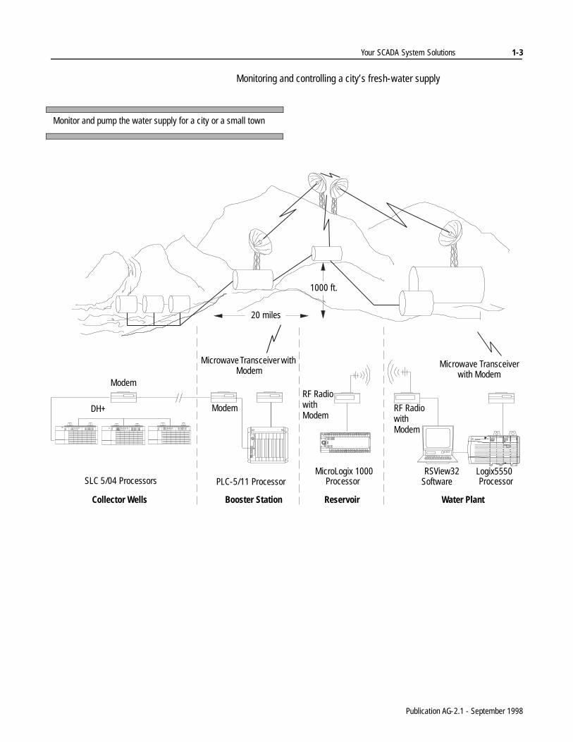
Monitoring and controlling a city’s fresh-water supply
Monitor and pump the water supply for a city or a small town
SLC 5/04 Processors PLC-5/11 ProcessorMicroLogix 1000
ProcessorRSView32
SoftwareLogix5550Processor
20 miles
1000 ft.
Collector Wells Booster Station Reservoir Water Plant
Modem
DH+
RF Radiowith Modem
RF Radiowith Modem
Modem
Microwave Transceiver with Modem
Microwave Transceiver with Modem
Publication AG-2.1 - September 1998

1-4 Your SCADA System Solutions
Monitoring and controlling thousands of I/O points distributed over a large geographical area
41124
Monitor and control offshore oil or gas pumping platforms fromthe land-based refinery. Integrate the data you gather into theoverall process for producing and shipping the final petroleumproduct
Remote Station
Remote Station
Remote Station Remote Station Remote Station Remote Station Remote Station Remote Station
Unloading Storage Facility
Mainline Pump Station
Mainline Pump Station
Refinery Storage Storage/Delivery Facility
Refinery Storage
Storage Tanks
Storage Tanks
Storage Tanks
Storage Tanks
Unloading Dock Metered Truck Rack
Computer Workstation
Computer WorkstationDCE
Server
Ethernet
PLC-5/40E
Publication AG-2.1 - September 1998

Your SCADA System Solutions 1-5
es
r
all
Flexibility Allen-Bradley has developed a close relationship with several companies who supply SCADA-related hardware and software. Through the Encompass Program, we reference hardware and software companies that provide you with additional products to meet your application needs. We review each company to make certain it provides the quality and service you deserve. Refer to the Encompass Program Product Directory for the latest information.
With products supplied by Encompass Program members, use Allen-Bradley master and remote stations with other protocols, such as:
• Modbus
• Teledyne-Brown Control Applications (CA)
• DNP 3.0
Use data communication equipment supplied by Encompass Program members to connect to a variety of communication media, such as:
• telephone
• radio
• power lines
Products Designed forSCADA Applications
Key features built into Allen-Bradley products help provide a one-stop SCADA solution.
Choose from many sizes of programmable controllers for master station and remote station control needs.
• Select one or more Logix5550 processors in a rack with one ormore Ethernet, ControlNet and/or DH+ communication modulto fit your most demanding master station and remote station requirements.
• Select an Enhanced PLC-5 processor from six available memory sizes to fit your medium to large master station and/oremote station requirements in single or redundant configurations.
• Select a SLC 5/03, SLC 5/04 or SLC 5/05 processor to fit your master station and/or remote station requirements for smto medium applications.
• Select a MicroLogix 1000 (with or without analog I/O) to fit your small remote station applications.
Integral communication means less equipment to buy.
• Logix5550, Enhanced PLC-5, SLC 5/03, SLC 5/04, SLC 5/05 and MicroLogix 1000 processors provide built-in support for serial communication links.
• Select an Ethernet PLC-5 or SLC 5/05 processor not only for built-in serial communication but also for built-in Ethernet connectivity that uses standard TCP/IP protocol.
Publication AG-2.1 - September 1998

1-6 Your SCADA System Solutions
be
ss a
of on em.
it.
the r
• Use the Logix5550 processor in a ControlLogix Gateway to bridge a large MIS application via Ethernet to master station control.
Fulfill your host computer software and master station needs by using Rockwell Software RSView32 software.
• With RSView32 MMI software and RSLinx 2.0 Communications Server software, your personal computer cana master station and an operator interface to your system.
• Using the RSView32 Active Display option, multiple workstations can access and share a common database acrolocal area or wide area Ethernet network.
• Add RSLogix programming software, and the RSView32 workstation can become the system programming terminal forboth local and remote stations.
Using Allen-Bradley DF1 half-duplex protocol provides these advantages:
• You do not have to program the master station to read blocks data from each remote station to determine if the remote statihas new data. Get data from remote stations by just polling thRemote stations can collect data on their own and have the message blocks waiting to send when the master station polls
• Perform remote station-to-remote station messaging through master station without any special ladder logic in the master oincreased processing time.
• Program remote stations over the telemetry network without interrupting the master station's normal control and data acquisition functions.
Publication AG-2.1 - September 1998

Your SCADA System Solutions 1-7
ms
e
o
Control System Experience Our many years of control system experience and a broad product line can provide you with a total system solution. Choose from our many:
• push-button and switches
• programmable controllers
• I/O modules
• operator interfaces
• development software packages
• industrialized computers
• specialized PLC-based hardware and software that support process control, motion control, ac/dc drives, and vision syste
Support A world-wide technical support network helps answer your questions.
• Allen-Bradley Technical Support provides help for you over thtelephone or at your control sites.
• Allen-Bradley uses local distributors to provide quick turn-around on your orders and local support. While no one knows your Allen-Bradley products better than Allen-Bradley, none knows your local situation better than your local Allen-Bradley distributor.
• Many Allen-Bradley and Rockwell Software product training courses are available. For information about available trainingprograms, contact your local Allen-Bradley sales office or distributor.
Publication AG-2.1 - September 1998

1-8 Your SCADA System Solutions
Selecting System Components
Each section describes a specific component and presents selection criteria to help you make appropriate choices for your application.
41125
To select SCADA system components:
1. Choose a telemetry network (if not specified).
2. Choose data communication equipment (DCE).
3. Choose a master station and (if necessary) an operator interface.
4. Choose a remote station for the local control site.
5. For modular processors, select appropriate input/output modules to monitor and control the application.
3. Master Station
or or
RS-232RS-232RS-232
1. Telemetry Network
2. DCE
4. Remote Station
4. Remote Station4. Remote Station
5. SLC 5/03 with I/O Modules
Ethernet
Publication AG-2.1 - September 1998

Your SCADA System Solutions 1-9
Selection Worksheet Use this worksheet as a quick guide to specifying a system.
For this component: Choose: See: Record your selection(s):
Telemetry Network topology• point-to-point• point-to-multipoint• multipoint-to-multipoint
page 2-2
transmission mode• half-duplex• full-duplex
page 2-3
link media page 2-3
protocol page 2-8
Data Communication Equipment Choose DCEs based on the following:• link media• transmission requirements• diagnostic requirements• master and remote station needs• application
page 3-1
Master Station Choose a master station based on the following:• functionality required (I/O to scan, amount of data to be
collected, operator interface needed)• quantity of remote stations • protocol being used• other application requirementsMake sure you have the following:• a serial interface• the proper equipment for the protocol you are using• power for the stationDepending on your choice, choose other components you may need:• I/O modules and chassis• local area network components• enclosures
page 4-1
Operator InterfaceSubmaster Station
Depending on the size of your application, you may need operator interfaces or submaster stations.
page 4-8
Remote Stations Choose a remote station based on the following:• functionality required• quantity of I/O points being controlled• power availability• space• location of the remote station• other application requirementsChoose control system components:• I/O modules and chassis• enclosures• operator interfaces• protocol being used
page 5-1
Publication AG-2.1 - September 1998

1-10 Your SCADA System Solutions
What To Do Next See the following chapters for more information on setting up your SCADA system.
For more information about: See page:
choosing a telemetry network 2-1
choosing data communication equipment 3-1
choosing a device for a master station 4-1
choosing a device for a remote station 5-1
third-party supplier contact information A-1
terminology Glossary
Publication AG-2.1 - September 1998

Chapter 2
Choosing a Telemetry Network
Overview A telemetry network provides the communication pathway in a SCADA system. These components make up a telemetry network:
Remember that an application can have more than one telemetry network. In some critical applications you may want to design a back-up system or recovery procedure for your main network. So, analyze your requirements and select telemetry networks accordingly.
transmit
41126
Master Station
Data Communication Equipment
transmit
DF1Topology
point-to-pointTopology
point-to-multipoint
Link Media
Link Media Link Media
DF1
DF1 DF1 DF1
Transmission Mode:full-duplex
Protocol: DF1
transmit
receive transmit
receive
receive receive
Remote Station Remote Station Remote Station
Transmission Mode:half-duplex
Protocol: DF1
Design the network by choosing each piece.
For more information about: See page:
choosing topologies 2-2choosing transmission lines 2-3choosing link media 2-3choosing protocols 2-8
Publication AG-2.1 - September 1998

2-2 Choosing a Telemetry Network
Choose a Topology Topology is the geometric arrangement of nodes and links that make up a network. For a SCADA system, choose among these topologies:
Topology: Definition: Comments:
Point-to-Point Communication link between only two stationsEither station can initiate communication with the other, or one station can inquire and control the other.
The stations can be connected by using: • cables or permanent public media like leased
telephone lines or digital data services• temporary connections, such as dial-up lines or
microwave, radio, or satellite transmissionsChoose this topology if you need a peer-to-peer communication connection, such as a back-up communication link between remote stations at a site and the master station at the control site.
generally a 2-wire connection
Two-wire means that transmission media type uses two wires for signal transmission/reception.Since a public switched telephone network provides a 2-wire connection, the topology used for a dial-up line is 2-wire point-to-point.
Point-to-Multipoint(multidrop)
Communication link among three or more stations with one station being a communication arbitrator (master) that controls when the other stations (remote stations) can communicate
The stations can be connected by using: • permanent public media like leased lines or digital
data services• atmospheric connections, such as microwave, radio,
or satellite transmissionsPoint-to-multipoint is the main topology for SCADA applications.
Four-wire means that transmission media type uses four wires for signal transmission/reception, one pair to transmit and one pair to receive.Private leased lines and digital data services provide four-wire, point-to-multipoint connections.
Multipoint-to-Multipoint
Communication link among three or more stations where there is no communication arbitrator (master) and any station can initiate communications with any other station.
This is a special radio modem topology that is supported by some suppliers. It provides a peer-to-peer network among stations.
a radio modem connection
modemstation stationmodem
DTE DCE DCE DTE
modem
master
remote
modem
remote
modem
station
radiomodem
radiomodem
station
station
radiomodem
radiomodem
station
Publication AG-2.1 - September 1998

Choosing a Telemetry Network 2-3
Choose a Transmission Mode Transmission mode is the way information is sent and received between and/or among devices on a network. For SCADA systems, your network topology generally determines your data transmission mode.
Choose a Link Media When choosing a link media, consider such items as the following:
• data transmission needs of the application
• remote site and control center locations
• distance between sites
• available link media services
• project budget
If you have chosenthis topology:
Then your transmission mode is: Which means:
point-to-multipoint half-duplex
point-to-point full-duplex
multipoint-to-multipoint full-duplex (between station and modem)half-duplex (between modems)
Information is sent in one direction at a time over the link.
stationA
stationB
transmit receive
receive transmit
Information is simultaneously sent and received over the link.
stationA
stationB
transmit
transmitreceive
receive
stationA
modemA
transmit
transmitreceive
receivemodem
B
transmit receive
receive transmit
stationB
transmit
receivetransmit
receive
Publication AG-2.1 - September 1998

2-4 Choosing a Telemetry Network
The types of link media available are:
Type: Definition:
• Public transmission media– Public Switched Telephone
Network (PSTN); Internationally: General Switched Telephone Network (GSTN)
The dial-up network is furnished by a telephone company. This telephone line is the one that we use daily and that carries voice and data transmissions.
– Private Leased Line (PLL) PLL is a dedicated telephone line that is a permanent connection between two or more locations and that is used for analog data transmission. The line is available 24 hours a day. For the line to be used for voice communication, a voice option must be installed.
– Digital Data Service (DDS) DDS is a special wide-bandwidth private leased line that uses digital techniques to transfer data at higher speeds and at a lower error rate than private leased lines. The line is available 24 hours a day.
• Atmospheric media
– Microwave Radio Microwave radio is a high-frequency (GHz), terrestrial radio transmission and reception media that uses parabolic dishes as antennas. The dishes are usually mounted on towers or on tops of tall buildings, since this is a line-of-sight topology.
– VHF/UHF Radio VHF/UHF radio is a high-frequency electromagnetic, wave transmission. Radio transmitters generate the signal, and a special antenna receives it.
– Geosynchronous satellite Geosynchronous satellites use a high-frequency (GHz) radio transmission to route transmissions between sites. The satellite's orbit is synchronous with the earth's orbit (geosynchronous orbit); therefore, the satellite remains in the same position with respect to the earth. Satellites receive signals from and send signals to parabolic dish antennas.
• Power line With special data communication equipment, you can transmit and receive data over 120V ac or 460V ac power bars within a factory.
% %
Phone CompanyPLL PLL
Phone CompanyDDS DDS
RadioModem
RadioModem
Earth
Publication AG-2.1 - September 1998

Choosing a Telemetry Network 2-5
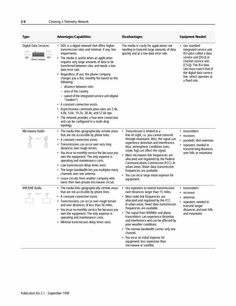
Before choosing a medium, consider these advantages and disadvantages:
Type: Advantages/Capabilities: Disadvantages: Equipment Needed:
Public Switched Telephone Network
• The media is cost effective for applications that require the following: – short, occasional data collection from
remote sites that have access to a PSTN– a site to call into a central location
Often point-to-point applications have a dial-up connection as a back-up to the main link media.
• The phone company charges you a monthly fee based on use - the number of local connections made and/or the time and distance of each long distance connection.
• The network supports communications rates of up to 33,600 bps.
• The network is a 2-wire connection that supports half-duplex modems and 2-wire, full-duplex modems. The topology is point-to-point.
• Transmission is costly for long, frequent data collection from remote sites.
• The lines can contain impairments that can cause modems to have error rates of less than 1 error per 1,000,000 bits.
• The media cannot be used in areas that do not have access to the network, such as an offshore oil or gas well.
• Time is required to dial and establish each connection.
• Additional logic is required to automatically initiate a connection.
• Use standard Bell or Consultive Committee for International Telephone and Telegraph (CCITT) modems.
• Contact the telephone company for information about connecting to the network.
Private Leased Line • The media is cost effective for applications that require large amounts of data to be frequently collected from remote sites and/or require remote sites to have a constant connection to the master station.
• Regardless of how much you use the line, the phone company charges you a flat, monthly fee based on the following:– distance between sites– area of the country– type of line conditioning
Leased lines have different levels of conditioning, or grades - the higher the grade, the greater the modem data rate that can be supported by the link, and the more the phone company charges for it.
• The standard, unconditioned line, supports speeds of up to 28,800 bps.
• Private leased lines provide a 4-wire connection. You can purchase modems that operate the circuit in either half- or full-duplex mode. You can also order a 4-wire multi-drop line.
• The media cannot be used in areas that do not have access to the network, such as an offshore oil or gas well.
• The lines can contain impairments that can cause modems to have error rates of less than 1 error per 1,000,000 bits.
• Use standard Bell or CCITT modems.
• Contact the telephone company for information about connecting to the network.
% %
PLL PLLPhone Company
Publication AG-2.1 - September 1998
2-6 Choosing a Telemetry Network
Digital Data Services • DDS is a digital network that offers higher transmission rates and minimal, if any, line impairments.
• The media is useful when an application requires very large amounts of data to be transferred between sites and needs a low data error rate.
• Regardless of use, the phone company charges you a flat, monthly fee based on the following: – distance between sites– area of the country– speed of the integrated service unit (digital
“modem”)• A constant connection exists.• Asynchronous communication rates are 2.4k,
4.8k, 9.6k, 19.2k, 38.4k, and 57.6k bps.• The network provides a four-wire connection
and can be configured in a multi-drop topology.
The media is costly for applications not needing to transmit large amounts of data quickly and at a low data error rate.
• Use standard integrated service unit, ISU (also called a data service unit [DSU] or channel service unit [CSU]). The ISU data rate must match that of the digital data service line, which operates at a fixed rate.
Microwave Radio • The media links geographically-remote areas that are not accessible by phone lines.
• A constant connection exists.• Transmissions can occur over very long
distances over rough terrain.• You incur no monthly service fee because you
own the equipment. The only expense is operating and maintenance costs.
• Low transmission delay times exist.• The larger bandwidth lets you multiplex many
channels over one antenna.• Lease circuits from another company who
owns their own private microwave circuit.
• Transmission is limited to a line-of-sight, i.e. you cannot transmit through mountains. Also, the signal can experience distortion and interference. Also, atmospheric conditions (rain, snow, fog) can affect the signal.
• Most microwave link frequencies are allocated and regulated by the Federal Communications Commission (FCC). In urban areas, fewer data-transmission frequencies are available.
• You can incur large initial expense for equipment.
• transmitters• receivers• parabolic dish antennas• repeaters needed to
transmit long distances over hills or mountains
VHF/UHF Radio • The media links geographically-remote areas that are not accessible by phone lines.
• A constant connection exists.• Transmissions can occur over rough terrain
and over distances of less than 30 miles.• You incur no monthly service fee because you
own the equipment. The only expense is operating and maintenance costs.
• Minimal transmission delay times exist.
• Use repeaters to extend transmissions over distances larger than 15 miles.
• Most radio link frequencies are allocated and regulated by the FCC. In urban areas, fewer data-transmission frequencies are available.
• The signal from 900MHz and above transmitters can experience distortion and interference and can be affected by poor weather conditions.
• The narrow bandwidth carries only one channel.
• You incur an initial expense for equipment; less expensive than microwave or satellite.
• transmitters• receivers• antennas• repeaters needed to
transmit longer distances and over hills and mountains
Type: Advantages/Capabilities: Disadvantages: Equipment Needed:
Phone CompanyDDS DDS
Publication AG-2.1 - September 1998
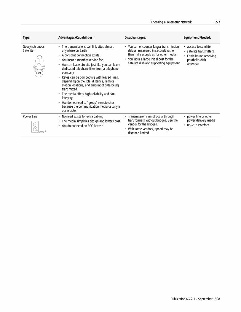
Choosing a Telemetry Network 2-7
Geosynchronous Satellite
• The transmissions can link sites almost anywhere on Earth.
• A constant connection exists.• You incur a monthly service fee.• You can lease circuits just like you can lease
dedicated telephone lines from a telephone company
• Rates can be competitive with leased lines, depending on the total distance, remote station locations, and amount of data being transmitted.
• The media offers high reliability and data integrity.
• You do not need to “group” remote sites because the communication media usually is accessible.
• You can encounter longer transmission delays, measured in seconds rather than milliseconds as for other media.
• You incur a large initial cost for the satellite dish and supporting equipment.
• access to satellite• satellite transmitters• Earth-bound receiving
parabolic-dish antennas
Power Line • No need exists for extra cabling• The media simplifies design and lowers cost• You do not need an FCC license.
• Transmission cannot occur through transformers without bridges. See the vendor for the bridges.
• With some vendors, speed may be distance limited.
• power line or other power delivery media
• RS-232 interface
Type: Advantages/Capabilities: Disadvantages: Equipment Needed:
Earth
Publication AG-2.1 - September 1998

2-8 Choosing a Telemetry Network
g
n
g
ol
l
Choose a Protocol A protocol governs the format of data transmission between two or more stations, including handshaking, error detection, and error recovery. When choosing a protocol, you must select one that best fits your application’s:
• connection topology
• transmission mode
• other application requirements, such as connections to existinequipment
If all the control products used in your point-to-multipoint applicatioare A-B products, use the DF1 half-duplex protocol because it provides benefits, such as:
• remote data table monitoring and online programming by usinstandard Rockwell Software programming software
• remote station-to-remote station messaging
• a more cost-effective solution since the protocol is built into Allen-Bradley products
DF1 protocol is an asynchronous, byte-based protocol.
You may need to choose a non-DF1 protocol if you are:
• using links, such as satellite or packet radio, that may require software handshaking to communicate
• expanding an existing system (you are adding A-B remote stations) or specifying a retrofit, which is not using DF1 protoc
• emulating someone else's product with an A-B programmablecontroller
If you do need to use an alternate protocol, our third-party protocosuppliers provide gateway solutions between A-B devices and devices that communicate by using non-DF1 protocols. See the following table for a list of third-party protocol suppliers.
If your transmission mode is: Then choose this type of protocol:
bidirectional but one direction at a time half-duplex
simultaneously bidirectional full-duplex
Publication AG-2.1 - September 1998

Choosing a Telemetry Network 2-9
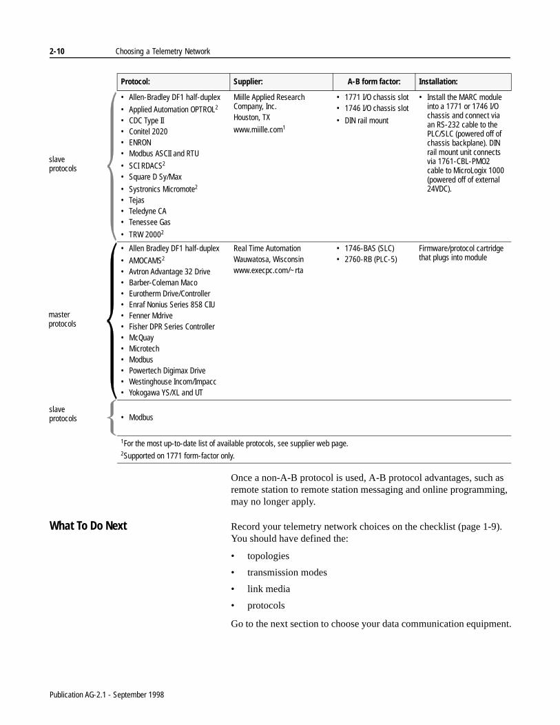
Table 2.A Use this table to help direct you to a third-party protocol supplier. You can find their addresses in appendix A.
Protocol: Supplier: A-B form factor: Installation:
• Allen-Bradley DF1 half-duplex• DNP 3.0• Emerson FX Drive• Honeywell 7800 Burner Control• IEC 870-5• Limitorque Valves• MDA Scientific CM4• MDA Scientific System 16• MetOne 215W• Modbus ASCII and RTU• MTS Level Plus• Mycom Compressors• Precision Engine Controls• SEAbus• York Chiller XTACK
ProSoft Technology, Inc.Bakersfield, CA
www.prosoft-technology.com1
• 1771 I/O chassis slot• 1746 I/O chassis slot
• Install the ProSoft module into a 1771 or 1746 I/O chassis. Communication with the processor takes place across the chassis backplane.
• Install the ProSoft RTU 5/03 processor with built-in Modbus slave protocol into a 1746 I/O chassis. Modbus slave communication with the processor takes place through channel 0
• DNP 3.0• IEC 870-5• Harris 5000/6000• Landis & Gyr 8979F• Metasys N2• Modbus ASCII and RTU• Systronics (VSAT supported)• Teledyne CA
• Allen-Bradley DF1 half-duplex• Caterpillar Gas and Diesel
Engine• Caterpillar Digital Voltage
Regulator• Controlotron• Danload 6000• Dynalco TM6000 and TEC9000• Modbus ASCII and RTU• Omron Host Link• Power Measurements Ltd.
ACM3720• Reliance Single and Multiple
Processor• SquareD Sy/Max
• Systronics MV22
• TRW S702
Miille Applied Research Company, Inc. Houston, TX
www.miille.com1
• 1771 I/O chassis slot• 1746 I/O chassis slot
• DIN rail mount
• Install the MARC module into a 1771 or 1746 I/O chassis and connect via an RS-232 cable to the PLC/SLC (powered off of chassis backplane). DIN rail mount unit connects via 1761-CBL-PMO2 cable to MicroLogix 1000 (powered off of external 24VDC).
1For the most up-to-date list of available protocols, see supplier web page. 2Supported on 1771 form-factor only.
master protocols
slave protocols
master protocols
Publication AG-2.1 - September 1998
2-10 Choosing a Telemetry Network
ent.
Once a non-A-B protocol is used, A-B protocol advantages, such as remote station to remote station messaging and online programming, may no longer apply.
What To Do Next Record your telemetry network choices on the checklist (page 1-9). You should have defined the:
• topologies
• transmission modes
• link media
• protocols
Go to the next section to choose your data communication equipm
• Allen-Bradley DF1 half-duplex
• Applied Automation OPTROL2
• CDC Type II• Conitel 2020• ENRON• Modbus ASCII and RTU
• SCI RDACS2
• Square D Sy/Max
• Systronics Micromote2
• Tejas• Teledyne CA• Tenessee Gas
• TRW 20002
Miille Applied Research Company, Inc. Houston, TX
www.miille.com1
• 1771 I/O chassis slot• 1746 I/O chassis slot
• DIN rail mount
• Install the MARC module into a 1771 or 1746 I/O chassis and connect via an RS-232 cable to the PLC/SLC (powered off of chassis backplane). DIN rail mount unit connects via 1761-CBL-PMO2 cable to MicroLogix 1000 (powered off of external 24VDC).
• Allen Bradley DF1 half-duplex
• AMOCAMS2
• Avtron Advantage 32 Drive• Barber-Coleman Maco• Eurotherm Drive/Controller• Enraf Nonius Series 858 CIU• Fenner Mdrive• Fisher DPR Series Controller• McQuay• Microtech• Modbus• Powertech Digimax Drive• Westinghouse Incom/Impacc• Yokogawa YS/XL and UT
Real Time AutomationWauwatosa, Wisconsinwww.execpc.com/~rta
• 1746-BAS (SLC)• 2760-RB (PLC-5)
Firmware/protocol cartridge that plugs into module
• Modbus
Protocol: Supplier: A-B form factor: Installation:
1For the most up-to-date list of available protocols, see supplier web page. 2Supported on 1771 form-factor only.
slave protocols
master protocols
slave protocols
Publication AG-2.1 - September 1998

Chapter 3
Choosing Data Communication Equipment
Overview Data Communication Equipment (DCE) is the link between a transmission medium and master and remote stations (data terminal equipment or DTE). Data communication equipment includes phone and radio modems as well as microwave and satellite transmission equipment.
41127
Choose that data communication equipment appropriate for the communication media you have chosen.
For more information about: See page:
choosing a telephone modem 3-2choosing integrated service units 3-6choosing a satellite transmission system 3-12choosing power line modems 3-13what to do next 3-14
Master Station
Remote Station Remote Station Remote Station
Publication AG-2.1 - September 1998

3-2 Choosing Data Communication Equipment
Choose a Telephone Modem Modems convert digital information from a programmable controller or computer to an analog signal that is compatible with the communication media being used. The signal is then transported to the receiving modem, which converts the analog signal back into a digital one (Figure 3-1).
Figure 3.1 In this example, digital data from each DTE is converted to an analog signal for transmission over the communication media.
Two modem technology standards exist to make certain that modems developed by different manufactures are compatible:
In most cases, the two modem types are not compatible. Keep this in mind when choosing modems for stations that are being added to or are retrofits to an existing installation. Compatibility charts exist; consult a modem supplier for more information.
Use the selections that you recorded from the previous section, “Choosing a Telemetry Network,” to answer these questions:
✔ What type of link(s) are you using to transmit data (PSTN, private leased line, radio, etc.)?
✔ What transmission mode(s) are you using (half-duplex, full-duplex)?
✔ What are your network topologies (point-to-point, point-to-multipoint)?
✔ Are you using 2-wire or 4-wire lines?
DTE DCE DTE
12678-I
DCE
Type: Explanation:
Bell The Bell standard was the predominant standard in the United States until the break-up of AT&T in the USA.
Consultive Committee for International Telephone and Telegraph (CCITT)
The CCITT standard is the international standard that is now becoming the standard for the USA. Most modems now conform to one or more of the CCITT standards, such as V.32, V.32bis, V.22, etc.
Publication AG-2.1 - September 1998

Choosing Data Communication Equipment 3-3
one
a vary
Once you know the type of modem, use these criteria to help you choose appropriate models:
✔ needed data communication rate
✔ requirements of the DTE devices to which you are connecting
– Do you need asynchronous or synchronous operation?
Note: If you are using all A-B DTE devices, choose an asynchronous modem.
– What interfaces do you need (RS-232, MIL 188, EIA-449,IEEE 488, CCITT V.24)?
– What other features are required to support your DTEs?
✔ required standards (UL, CSA, FCC, etc.)
✔ space requirements. Do you need a rack-mounted or stand-almodem?
✔ input-power requirements
✔ ambient temperature specifications
✔ modem design and operation
✔ modem response time
Once you have a good idea of the modem type you need, choosemodem based on the many available features and options, which by manufacturer.
For information about this modem type: See page:
Analog dial-up 3-4
Analog leased-line 3-5
Digital leased-line 3-6
Publication AG-2.1 - September 1998

3-4 Choosing Data Communication Equipment
Analog Dial-up Modem
Table 3.A lists the modem features that are required by certain A-B DTE devices. Since you may not know the exact programmable controller or computer your application needs, you may need to refer to this table after you have chosen your DTEs to finalize your modem selection.
Table 3.A Keep these requirements in mind when choosing analog dial-up modems for A-B DTEs.
See Table 3.B for a listing of recommended modem suppliers and respective modem models.
Table 3.B Use these recommendations to help you choose analog dial-up modems. Consult the vendor for information about their product offerings.
% %
If you are using this DTE: The DTE needs support for:Make certain the modem you choose has this feature:
• Logix5550 processors• Enhanced PLC-5 processors• SLC 5/03, 5/04, and 5/05 processors• RSLinx 2.0 Software
ASCII strings to configure and control the dial-up modem
AT-command-set support
• 1747-KE• 1785-KE• 1770-KF2 • 1770-KF3
auto answer capability and hang-up control via the RS-232 DTR signal line
configurable to auto answer when DTR (data transmit ready signal) is high and hang-up the current connection when DTR switches from high to low
• MicroLogix 1000 controllers answer capability only auto answer support
Supplier:MaximumTransmission Rate:
Modem Model:
DATA-LINC Group 28,800 DLM41001
DLM4200CP1 2
Miille Applied Research Co. Inc. 2400 166-100 (1746 rack mount)
2400, 14,400 and 28,000
166-010 (1771 rack mount)
1 1746 and 1771 rack mount available.2 Cellular phone compatable.
Publication AG-2.1 - September 1998

Choosing Data Communication Equipment 3-5
d
Analog Leased-Line Modems
Table 3.C describes the type of modem you should choose.
Table 3.C Keep these considerations in mind when choosing leased-line modems.
Depending on the speed of the modem you choose, you may need a better conditioned line. A leased-line modem’s cost is composed of two principal items:
• monthly leased-line charges, which are directly proportional tothe conditioning or communication rate capability of the leaseline
• modem price, which is directly proportional to the modem's communication rate capability
For this application: Choose this modem type:
Point-to-point, full-duplex any asynchronous, full-duplex 2-wire or 4-wire leased-line modem pair
Point-to-multipoint,half-duplex
asynchronous, point-to-multipoint operation over a 4-wire or 2-wire leased lineTypically these modems have a “Master” setting for the modem connected to the master station and a “Slave” setting for the modems that connect to remote stations.• For the master station: choose a modem that has the
capability of holding the modem carrier high so that no time is lost waiting for the modem carrier to turn on and stabilize whenever the “Master” modem has data to transmit.
• For the remote stations: choose a modem that can switch the carrier on and off, whether transmitting or receiving, based on RTS/CTS signal handshaking with the other remote stations. You need to use switched modem carrier since the stations share the same leased-line channel and would jam each other's data transmission attempts if two or more remote station modems set their carriers high at the same time.
Using a half-duplex mode virtually guarantees that no two remote stations will attempt to transmit data at the same time.
Whether an application uses 2-wire or 4-wire leased lines, choose remote modems that support switched modem carriers.
Phone CompanyPLL PLL
Publication AG-2.1 - September 1998

3-6 Choosing Data Communication Equipment
e
Therefore, the most efficient system matches the maximum communication rate of the modem to that of the leased line to which the modems are attached.
See Table 3.D for a listing of recommended analog leased-line modem suppliers and respective modem models.
Table 3.D Use these recommendations to help you choose analog leased-line modems. Consult the vendor for information about their product offerings.
Digital Leased-Line ISUs
Integrated Service Units (ISUs) are the modem equivalents for the digital data service lines. You can use the DDS network for point-to-point and point-to-multipoint systems. Two components make up an ISU (Figure 3-2):
• data service unit (DSU), connects to the RS-232 link
• channel service unit (CSU), transmits the digital signal onto thcommunication line
Figure 3.2 Integrated service units are the DCEs for the digital data service lines.
Supplier: Transmission Rate: Topology: Modem Model:
DATA-LINC Group
1200 point-to-point2 LLM1000-46
point-to-multipoint2
point-to-multipoint5 LLM1000-26
28,800 point-to-point5 DLM4000
Miille Applied Research
1200 point-to-multipoint3
point-to-point3 4
166-101 (1746 rack mount)
point-to-multipoint3
point-to-point3 4
137-001 (1771 rack mount)
148-001 (1771 rack mount)1
1Dual/redundant modem.24-wire leased line only.32-wire or 4-wire leased line.42-wire maximum transmission rate is 300 baud.52-wire leased line only.61746 and 1771 rack mount available.
Phone CompanyDDS DDS
DTE DSU DTE
41140
CSU
ISU
CSU DSU
ISU
Publication AG-2.1 - September 1998

Choosing Data Communication Equipment 3-7
The data rate for the ISU must match that of the DDS line. Some ISUs can operate at multiple rates, but the rate of a DDS line is fixed.
Typical asynchronous DDS line speeds are 9600, 19.2k, 38.4k, and 57.6k bits per second.
Telephone Modem and ISU Installation Guidelines
Telephone modems and ISUs require a telephone-company approved connector. Consult your modem/ISU vendor for installation requirements.
Choose a Radio Transmission System
You can use radio modems for either point-to-point, point-to-multipoint, or multipoint-to-multipoint applications.
The primary selection consideration for radio modems is the radio frequency band in which they operate. You can choose among theseradio types:
Also, consider the following criteria while choosing radios:
✔ required communication rate
✔ space requirements. Do you need a rack-mounted orstand-alone modem?
✔ requirements of the DTE devices to which you are connecting
– Do you need asynchronous or synchronous operation?
Note: If you are using all A-B DTE devices, choose an asynchronous modem interface.
– What interfaces do you need (RS-232, MIL 188, EIA-449,IEEE 488, CCITT V.24)?
– What other features are required to support your DTEs?
Table 3.E Use these recommendations to help you choose digital leased-line ISUs. Consult the vendor for information about their product offerings.
Supplier:Transmission
Rate:Topology: Modem Model:
DATA-LINC Group 57,600 point-to-point DLM-4300
point-to-multipoint
Radio Type: Frequency:
VHF 66-79 MHz150-174 MHz
UHF 450-470 MHz
higher frequency UHF 850-960 MHz
microwave 1 GHz and above
RadioModem
RadioModem
Publication AG-2.1 - September 1998

3-8 Choosing Data Communication Equipment
✔ required diagnostic features
Radio modems can either be crystal-based or microprocessor- based. Microprocessor-based modems can be more easily serviced and programmed from a central control site. Diagnostics can be more easily performed on microprocessor-based modems. Technicians do not have to travel to the remote site to diagnose problems; they can perform diagnostics at the control site.
✔ power availability at the remote sites
✔ required licensing
✔ required standards (UL, CSA, FCC, etc.)
✔ whether the radio modem is composed of an integrated unit or a radio and a modem as separate units
✔ radio modem design and operation
✔ needed response time
Licensing
The FCC requires that you obtain a license before you operate a radio modem at a particular location and frequency within certain radio frequency bands. The advantage of operating within a licensed radio frequency band is that this minimizes the chance of transmission interference from other nearby radio modems. The disadvantage is that in populated areas, most, if not all, of the available radio frequencies are already licensed and in use.
FCC allows you to use relatively low transmit power, spread-spectrum radio modems without a license. Spread-spectrum is a transmission-frequency varying technique that lets many spread-spectrum radios operate within the same radio frequency band with some interference. The amount of interference is directly proportional to the number of users in the area.
Publication AG-2.1 - September 1998

Choosing Data Communication Equipment 3-9
n.
r
e
e lay
Radio Modem Types
Radio modems may be sold as:
• integrated units
Key-up time between the radio and modem is integrated fully.The unit does not require programmable controller interventio
When the modem and transmitter/receiver are separate, compatibility becomes an issue.
• two separate units:
– a digital data modem that has an RS-232 connector
– a radio transmitter/receiver that has an antenna connecto
Often, since the modem is not able to directly control when thradio transmits a carrier, the data communication device mustalso have a way to key-up the radio transmitter just prior to transmitting data to the modem.
Also, consider the time-to-transmit power requirements of thecombination, since the external modem is not able to determinwhen the radio is at full power. The modem requires a time deprior to data transmission.
Table 3.F describes the type of modem you should choose.
Publication AG-2.1 - September 1998

3-10 Choosing Data Communication Equipment
Table 3.F Keep these considerations in mind when choosing radio modems.
Like leased-line modems, the cost of radio modems is directly proportional to the communication rate or communications throughput that they can support.
For this application:
Choose this modem type:
Point-to-point, full-duplex
full-duplex radiosThis application requires a separate transmitter and receiver in each radio modem.
Point-to-multipoint (or broadcast), half-duplex
full-duplex or half-duplex master radio, half-duplex remote radios For best performance use a “Master” radio modem capable of full-duplex operation, since a full-duplex radio modem has a transmitter that is separate from the receiver. This provides shorter RTS-to-CTS delays with each master station data transmission. To be cost efficient, use radio modems for the remote stations that have a transceiver. Having a transceiver limits modems to only half-duplex operation, since they can only send or receive data at one time. Therefore, with each remote station transmission, the RTS-to-CTS delay is longer, since the transceiver takes time to switch from receiver operation to transmitter operation. This time delay lets the transmitter fully power up. Also, think about setting up your master station in a redundant configuration. If the master station's radio modem goes down, the whole communications system is down. Whereas, when a remote station radio modem goes down, only communications to a single remote station is lost.
Multipoint-to-multipoint, full-duplex
packet radiosAlthough packet radio modems receive and transmit across the airwaves in a half-duplex fashion, they are able to buffer and interpret data received from the attached PLC/SLC that is configured to communicate using DF1 full-duplex protocol. This allows any station to trigger a message instruction in ladder logic and immediately transmit it to the attached radio modem. It is up to its radio, then, to successfully deliver the message packet to the appropriate remote radio modem and its attached station based on the DF1 destination address embedded within the message packet.
Publication AG-2.1 - September 1998

Choosing Data Communication Equipment 3-11
See Table 3.G for a listing of recommended radio modem suppliers and respective modem models.
Table 3.G Use these recommendations to help you choose radio modems.Consult the vendor for information about their product offerings.
Radio Modem Installation Guidelines
For a radio system, you need these components:
Supplier:Transmission
Rate:Frequency: Topology:
ModemModel:
DATA-LINC Group
115200 902-928 MHz1 point-to-pointpoint-to-multipoint
SRM60002
2400-2484 MHz1
point-to-pointpoint-to-multipoint
SRM61002
902-928 MHz1 point-to-pointpoint-to-multipoint
SRM6200E3
902-928 MHz1 point-to-pointpoint-to-multipoint
SRM6200E/FL2 4
ESTeem 19200 66-79 MHz multipoint-to-multipoint Model 192V
150-174 MHz multipoint-to-multipoint Model 192M
400-420 MHz multipoint-to-multipoint Model 192F
450-470 MHz multipoint-to-multipoint Model 192C
Metricom 9600 902-928 MHz1 multipoint-to-multipoint UtiliNet
MicrowaveData Systems (MDS)
1200, 4800, and 9600
920-960 MHz point-to-pointpoint-to-multipoint
Series 2000
390-470 MHz point-to-pointpoint-to-multipoint
Series 4000
19200 902-928 MHz1 point-to-pointpoint-to-multipoint
Series 9810
1Spread-spectrum Radio - NO FCC LICENSE REQUIRED.2 1746 and 1771 rack mount available.3 Ethernet 10BASE-T interface (no RS-232).4 Ethernet 10BASE-FL fiber optic interface (no RS-232).
Component: Comments:
antennas The height and quality depend upon the application and project budget.
cabinets Depending on the environmental conditions or the location of the remote sites, select an appropriate cabinet.
repeaters(optional)
If the radios are not located in a line of sight with each other (e.g., due to terrain), you may need repeaters that will carry the signal from initiating station to the destination station.
Publication AG-2.1 - September 1998

3-12 Choosing Data Communication Equipment
al ypes:
When becoming involved with radio system design, consult radio system vendors. A site survey should always be performed to determine the following:
• radio transmit power requirements
• quantity of radios
• whether or not repeaters are needed
• antenna type and heights
Choose a SatelliteTransmission System
A Very Small Aperture Terminal (VSAT) network provides a mechanism for multiple remote sites to communicate with a centrsite (a hub) on a shared access basis. You can choose from two t
System: Comments:
single-hop Data is transmitted across leased lines to the master Earth station, which beams the data to the satellite. The satellite beams the data to the remote sites (or master site).The charges may be high if you purchase your own inbound and outbound channels, and usually, you do not use the channels’ entire bandwidth. Also, you must pay for the leased line that transports the data to the master hub.You can choose a single-hop system that shares the inbound and outbound channels with others to offset costs.
double-hop A VSAT site is directly connected to your master or remote station. This VSAT beams the data to the satellite, which beams the data to either the remote site or master site.With a double-hop system, you are not dependent upon the availability of terrestrial leased lines.
Earth
Publication AG-2.1 - September 1998

Choosing Data Communication Equipment 3-13
These components make up a satellite transmission system:
Choose Power Line Modems You can easily integrate power line modems into your application. You need a power line or other power delivery media and an RS-232 interface.
See Table 3.H for a listing of recommended power line modem suppliers and respective modem models.
Table 3.H Use these recommendations to help you choose power line modems. Consult the vendor for information about their product offerings.
For installation requirements, consult the modem vendor.
41137
up/down converter
satellite modem A
remote unit
up/down converter
satellite modem B
remote unit
up/down converter
satellite modem
master station
Modulator
Demodulator A
Demodulator B
antenna
power amplifier (transmit)/low noise amplifier (receive)
power amplifier (transmit)/low noise amplifier (receive)
If each remote site communicates on a different frequency, then you need a demodulator for each frequency at the master station site
Satellite modems are typically supplied by a satellite vendor and bundled with the communication system.
For more information about satellite transmission systems, see a local satellite transmission system vendor
antenna
Supplier: Transmission Rate: Topology: Modem Model:
DATA-LINC Group maximum of 9600K bps on the power line
point-to-pointpoint-to-multipoint
LCM100-MLCM100-R
Publication AG-2.1 - September 1998

3-14 Choosing Data Communication Equipment
What To Do Next Choose your data communication equipment. You may need more specific information about control devices to which you are connecting. Therefore, after choosing your master and remote stations, refer to this section as needed to finalize your transmission system.
Go to the next section to choose master stations.
Publication AG-2.1 - September 1998

Chapter 4
Choosing a Device for a Master Station
Overview The master station in a SCADA system does the following:
• gets field data by periodically reading and/or receiving data directly from the remote stations or through a submaster
• provides coordinated monitoring and control over the entire system through its operator interface
Several master station types are possible:
For information about: See page:
choosing a VAX- or UNIX-based computer
4-3
choosing a personal-computer-based master station
4-3
choosing a programmable controller-based master station
4-6
choosing a submaster station 4-8
needed equipment 4-10
installation guidelines 4-10
what to do next 4-10
41130
4112841129
VAX-or UNIX-based computer Personal computer SLC, PLC or Logix processor
remote stations
remote stations
remote stations
remote stations
Ethernet DH+, Ethernet or ControlNetRS-232 links
RS-232
with Interchange
Have one or more VAX- or UNIX-based computers communicate with the master station through a local area network connection.Use them to initiate control actions to the remote stations via the master station
In small SCADA systems, a single personal computer can serve as both the master station and central computer
Use a programmable controller as a master station if an application requires one or more master station(s) separate from the operator interface, such as when you need to control local inputs and outputs
RSView32 software with RSLinx 2.0 software
Publication AG-2.1 - September 1998

4-2 Choosing a Device for a Master Station
nds
Very large applications can also require submaster stations, which:
• gather data from the remote stations within a region
• support local operator interface for the region
• support logging of alarms and events
• communicate remote station data and support control comma
• interface with a larger, host master station
A submaster station controls remote sites within a region.
41131
communication with master station
operator interface
master to remote sitesDH+ link
remote site A remote site B remote site C
Region 1
Submaster station collecting data for the region. Components: PLC-5 processor and 1785-KE, or SLC 5/03 processor and 1747-KE, or two Logix5550 processors in a chassis
Operator-interface applications display, log, trend, alarm upon, and report on the data collected by the submaster station
Publication AG-2.1 - September 1998

Choosing a Device for a Master Station 4-3
Choose a VAX- or UNIX-based Computer
Choose a VAX- or UNIX-based computer as a master station when your application has a very large number of remote stations to control. You can also use this type of system to maintain a system database, support a local operator interface, and generate reports and application programs. The application software utilizes Rockwell Software INTERCHANGE Application Programming Interface (API) to communicate over the Ethernet to the master data concentrator.
Choose a PersonalComputer-Based MasterStation
For many small SCADA configurations, a personal computer running Rockwell Software’s RSView32 and RSLinx 2.0 software can meet the requirements for both the operator interface and the master station. RSView32 software provides not only an operator interface but also master station functionality, both at the same time. This configuration provides for the most integrated and cost-effective master station for smaller applications.
41139
Requirements:
• workstations
• local area network and server
• operator interface software and/or data collection
• software programs INTERCHANGE API
Vax-based or UNIX-based servers supporting single or multiple workstations on a local area network
Workstation Workstation VAX or UNIX-based server
Ethernet network
Publication AG-2.1 - September 1998

4-4 Choosing a Device for a Master Station
Use RSView32 software as a master station.
A single RSView32-based workstation can simultaneously be:
• the host computer, running operator-interface software
• the master station, performing the remote station data-gathering functions
• the remote station programming terminal
To create a cost-effective solution, equip a workstation with the following:
• RSView32 software
• RSLinx 2.0 or higher communication server software
• RSLogix5, 500 or 5000 programming software
41132
l
l
l
l
l
l
RSView32 software with RSLinx 2.0 or higher
RS-232 circuit 4
RS-232 circuit 2
Data sharing
Ethernet
half-duplex protocol
half-duplex protocol
full-duplex protocol
or
Remote Stations
Remote Stations
Station connected via a point-to-point link
A total of 300 devices.
If only one circuit is used, the system can have 254 devices.
Each of up to four circuits support either DF1 half-duplex or DF1 full-duplex protocol. Using COM1-COM4 serial ports, you can have RSView32 software connected to four separate telemetry systems.
Therefore, an RSView32 master station can be a:• master station to four separate SCADA systems when each circuit is configured for DF1 half-duplex protocol• half-duplex master on up to three of its circuits and support DF1 full-duplex protocol with dial-up modem support on the other circuit,
which is a requirement for some SCADA applications
Even when multiple host computers are required, RSView32 Active Display Station option facilitates data sharing between the half-duplex master workstation and other RSView32 workstations over an Ethernet network.
Publication AG-2.1 - September 1998

Choosing a Device for a Master Station 4-5
Use RSView32 software as an operator interface.
Add RSLogix Frameworks function block programming software to a PLC-5 based master station system and you can configure process control functions and view the control process from one workstation. This software helps to simplify the task of integrating analog I/O modules, PLC-5 programmable controllers, regulatory loops, and operator interface workstations.
41133
Requirements:• personal computer with Windows 95 or NT• communication card• cables• RSView32 software• RSLinx communication server software (2.0 or
higher)• For the Logix, PLC or SLC-based master station
requirements, see Table 4.A
A personal computer running RSView32 software serves as an operator interface to a PLC-based master station on an Ethernet local area network
EthernetEthernet
Publication AG-2.1 - September 1998

4-6 Choosing a Device for a Master Station
Choose a ProgrammableController-basedMaster Station
Choose a programmable controller-based master station if any of these requirements exists:
• master station must be able to control local I/O
• application requires master station redundancy
Use this chart to help you choose a programmable controller master station.
Processor MemoryMaximum I/O
PointsRacks:
A-B RS-232 Interface
RS-232 Protocol:Maximum Remote
Stations1:
Represented in Kwords unless
notedTotal Local/Remote2 DF1 FDX
DF1 HDX Master
Modbus
SLC 5/03 8, 16 4096 32 32 built-in1747-KE1770-KF3
yesyesyes
yesnono
yes 3 4
nono
254
SLC 5/04SLC 5/05
16, 32, 64 4096 32 32 built-in yes yes yes 3 4
PLC-5/11™ 8 512 4 4/1 1770-KF21785-KEbuilt-in
yesyesyes
nonoyes
nono
yes 3 4PLC-5/20PLC-5/20CPLC-5/20E
16 512 4 4/3
PLC-5/30 32 1024 8 4/7
PLC-5/40PLC-5/40CPLC-5/40E
48 2048 16 4/15
PLC-5/40L 48 2048 16 4/15 (15 ext. local)
PLC-5/60PLC-5/60C
64 3072 24 4/23
PLC-5/60L 64 3072 24 4/23(23 ext. local)
PLC-5/80PLC-5/80CPLC-5/80E
100 3072 24 4/23
Logix5550 160 Kbytes 672 Kbytes1184 Kbytes2208 Kbytes
128K discrete4K analog
250 1/250 built-in yes yes no
1This quantity is the total number of nodes allowed on the network; a more efficient network uses fewer nodes.2Combination of local, extended local, and remote racks cannot exceed total number of racks available.3Obtain DF1 master and Modbus master station protocols from Miille Applied Research as single-slot modules for the 1746 and 1771 I/O chassis. The maximum number of remote stations for DF1 master is 128; for Modbus, 48. For contact information, see page A-1.4Obtain DF1 master and Modbus master station protocols from ProSoft Technologies as single slot modules for the 1746 and 1771 I/O chassis. The maximum number of remote stations for DF1 master is 50; for Modbus, 150. For contact information, see page A-1.
Publication AG-2.1 - September 1998
Choosing a Device for a Master Station 4-7
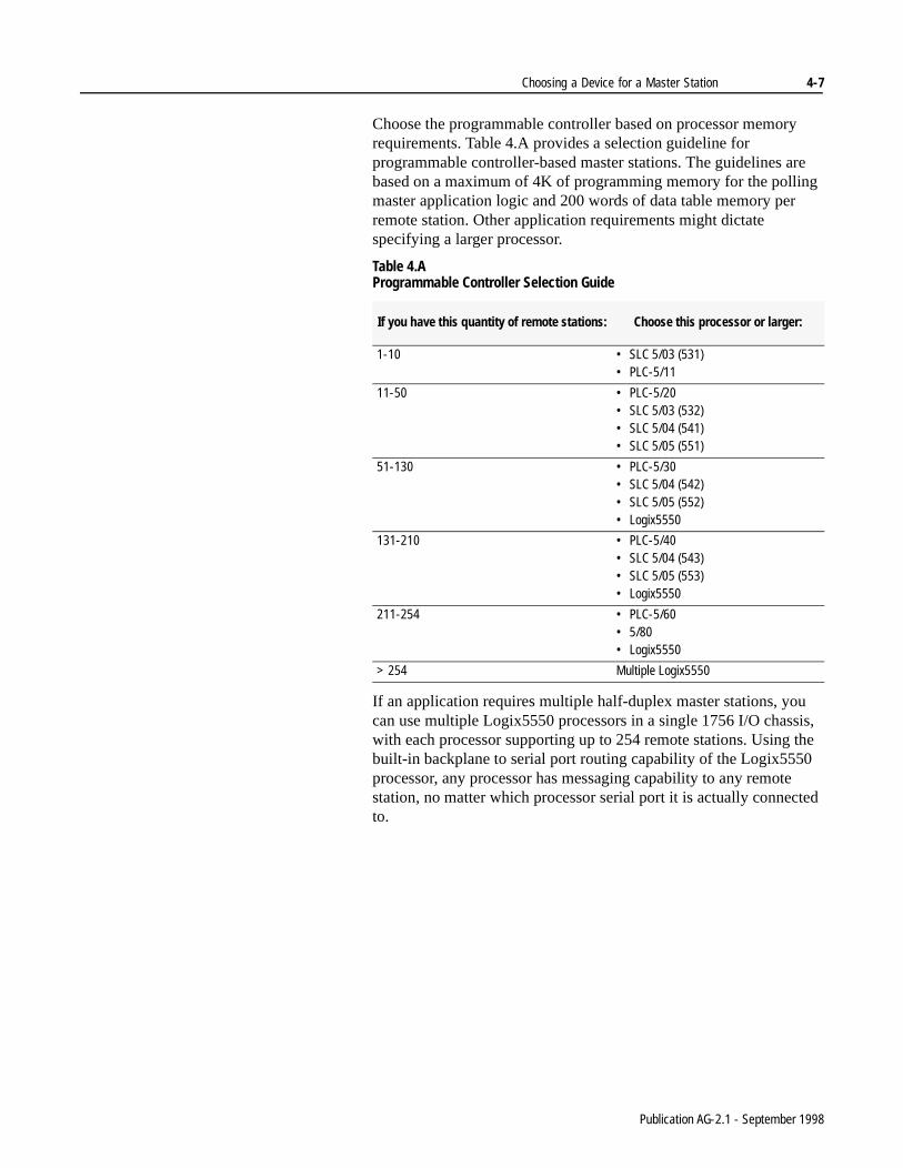
Choose the programmable controller based on processor memory requirements. Table 4.A provides a selection guideline for programmable controller-based master stations. The guidelines are based on a maximum of 4K of programming memory for the polling master application logic and 200 words of data table memory per remote station. Other application requirements might dictate specifying a larger processor.
Table 4.A Programmable Controller Selection Guide
If an application requires multiple half-duplex master stations, you can use multiple Logix5550 processors in a single 1756 I/O chassis, with each processor supporting up to 254 remote stations. Using the built-in backplane to serial port routing capability of the Logix5550 processor, any processor has messaging capability to any remote station, no matter which processor serial port it is actually connected to.
If you have this quantity of remote stations: Choose this processor or larger:
1-10 • SLC 5/03 (531)• PLC-5/11
11-50 • PLC-5/20• SLC 5/03 (532)• SLC 5/04 (541)• SLC 5/05 (551)
51-130 • PLC-5/30• SLC 5/04 (542)• SLC 5/05 (552)• Logix5550
131-210 • PLC-5/40• SLC 5/04 (543)• SLC 5/05 (553)• Logix5550
211-254 • PLC-5/60• 5/80• Logix5550
> 254 Multiple Logix5550
Publication AG-2.1 - September 1998

4-8 Choosing a Device for a Master Station
ng ter’s
e
rial .
Choose a Data Concentrating Submaster Station
If your application requires one or more data-concentrating submaster station(s), each submaster station must support both DF1 half-duplex master station and DF1 half-duplex remote station communication through two serial ports. In this application, the submaster can communicate directly with its master or its remote stations, but any data exchange between its master and its remote stations can only occur through the submaster’s data table. The master programmiterminal can remotely program the submaster, but not the submasremote stations.
Choose a Data Routing Submaster Station
If your application requires one or more data routing submaster station(s), the master station and the submaster station(s) must bLogix5550 processor-based. Each submaster station has two Logix5550 processors, one with its serial port configured for DF1 half-duplex master station communication and the other with its seport configured for DF1 half-duplex remote station communication
41134
Region 1
remote site A remote site B remote site C
DH+ linkDH-485 link
or
communication with master stationcommunication with master station
The PLC-5 or SLC 5/03 processor is configured for master mode. Connected to its serial port is the master modem connection to the remote stations.
The 1785-KE or 1747-KE module is the master station’s remote link to the submaster station for this region.
Publication AG-2.1 - September 1998

Choosing a Device for a Master Station 4-9
In this application, not only can the submaster communicate directly with its master or remote stations, but the master can initiate messages to the remote stations by routing through the submaster, with no additional programming or data table memory used in the submaster.
A programming terminal or MMI computer connected to the master station via Ethernet or ControlNet can also route through the master and submaster in order to program or exchange data with the remote stations.
41135
RSView32 RSLogix
MicroLogix remote Logix5550 remote SLC 5/03 remote
Logix5550 master station
Logix5550 submaster station
Ethernet or ControlNet Network
Publication AG-2.1 - September 1998
4-10 Choosing a Device for a Master Station
ny
Needed Equipment Allen-Bradley offers a wide variety of chassis, power supplies, and I/O modules to help you automate your application. See the Automation Systems Catalog for more information.
Installation Guidelines You must provide an appropriate environment and proper grounding for programmable controller systems. See the Programmable Controller Wiring and Grounding Guidelines, publication 1770-4.1, for more information.
What To Do Next You should:
• Choose your master and submaster stations and operator interfaces according to your application requirements. Recordthese choices on the checklist (page 1-9).
• Finalize any telemetry equipment decisions.
• Consult the Automation Systems Catalog to begin designing aneeded control systems.
Go to the next section to choose your remote stations.
Publication AG-2.1 - September 1998

nds
Chapter 5
Choosing a Device for a Remote Station
Overview A remote station in a SCADA application does the following:
• controls inputs and outputs of field devices, such as valves, metering equipment, and drives
• monitors conditions of the field devices and logs alarms
• reports status to the master station and carries-out the commait receives from the master station
For information about: See page:
choosing a device 5-2
needed equipment 5-7
installation guidelines 5-7
what to do next 5-7
41136
Master Station
Gas Metering Station
Waste-water Treatment Plant
Pump StationRemote SLC 5/03
Station
Remote MicroLogix 1000 Station
Pump Station
Remote Logix5550 Station
Remote PLC-5 Station
Publication AG-2.1 - September 1998

5-2 Choosing a Device for a Remote Station
Choose a Device Choose from a variety of remote stations that fit your application and cost requirements. The most cost-effective remote station for applications that use limited analog and/or discrete I/O is the MicroLogix 1000 programmable controller. Otherwise, choose a SLC 500 system for your remote station unless specific redundancy, I/O, or communication requirements are only met by a Logix5550 or PLC-5-based solution.
MicroLogix 1000 or SLC 5/0(x) Processor-based Remote Stations
Use this table to help you choose a MicroLogix 1000 or SLC programmable controller for your remote station(s).
If your application meets any of the following: Choose: Requirements:
• uses no analog I/O• discrete I/O requirement falls within either: 6 in/4 out,
10 in/6 out or 20 in/12 out
MicroLogix 1000 Programmable Controller
Built-in serial port. (Recommend using AIC+ to optically isolate serial port)
analog I/O requirements fall within:• 2 single-ended +/- 10.5 VDC inputs• 2 single-ended +/- 21 mA inputs• 1 single-ended 0-10 VDC or 4-20 mA outputdiscrete I/O requirement falls within: 12 in/8 out
MicroLogix 1000 Programmable Controllerwith Analog
Built-in serial port. (Recommend using AIC+ to optically isolate serial port)
• integrated dial-out phone modem control using ASCII instructions
• 8K, 16K, 32K, or 64K program/data table memory• floating point math and PID capability• online programming capability• key switch• built-in clock/calendar• separate local MMI/programming communication port• 48 VDC and 125 VDC power supply options
SLC 5/03, SLC 5/04 and SLC 5/05 Modular Controller
SLC 5/03, SLC 5/04 and SLC 5/05 processors have a built-in serial port as well as either a DH485, DH+ or Ethernet ports
• requires a protocol other than DF1• no need for remote station programming over the
telemetry system
third party module with a SLC 5/0(x) processor
See page 2-9 for protocol modules available from ProSoft Technology, Inc., Miille Applied Research Co., Inc., and Real Time Automation.
Publication AG-2.1 - September 1998

Choosing a Device for a Remote Station 5-3
ProcessorMemory(Kwords)
Maximum Local I/O Points # Local Chassis:A-B
RS-232 Interface
RS-232 Protocol:
DF1FDX
DF1 HDX Slave Modbus Slave
MicroLogix 1000 1 6 discrete in/ 4 discrete out10 discrete in/ 6 discrete out20 discrete in/ 12 discrete out
1 built-in yes yes yes2
MicroLogix 1000 with Analog
1 12 discrete in/ 8 discrete out4 analog in/ 1 analog out
1 built-in yes yes yes2
SLC 5/03 8, 16 4096 3 built-in1747-KE1770-KF3
yesyesyes
yesyesyes
yes1 2 3
no no
SLC 5/04SLC 5/05
16, 32, 64 4096 3 built-in yes yes yes1 2
1 Obtain Modbus remote station protocol from ProSoft Technology, Inc. as single-slot modules for the 1746 I/O chassis2 Obtain Modbus remote station protocols from Miille Applied Research Co. (MARC) as single-slot modules for the 1746 I/O chassis. MARC has also developed a stand alone, DIN-rail mount interface that converts DF1-full duplex to Modbus, and can be used to interface MicroLogix on Modbus. Contact MARC for details. 3 An equivalent SLC 5/03 processor with built-in Modbus is available from ProSoft Technology, Inc., as the RTU 5/03.
Publication AG-2.1 - September 1998

5-4 Choosing a Device for a Remote Station
, 40,
eed
es
PLC-5 Processor-based Remote Stations
Choose a PLC-5 processor if your application also requires:
• a redundant PLC processor system
• specific I/O requirements only met by 1771-based I/O
Generally a PLC-5/11 processor fits most PLC-5 processor-basedremote-station solutions. However, choose a PLC-5/20, -5/30, -5/-5/60, or -5/80 processor based strictly on memory size or I/O quantity requirements of your application. Enhanced PLC-5 processors provide a cost-effective solution because you do not nto purchase a separate serial interface.
Use a 1785-KE module as shown below, if your application requirmultiple PLC-5 processors located at a single remote site.
41138
The 1785-KE module is operating in remote slave mode.
The master station can directly solicit data from any PLC-5 system at the remote site via the DH+ link.
communication with master station
DH+ link
connected to 1785-KE
operator interface
DH+ link
Remote Site
Publication AG-2.1 - September 1998

Choosing a Device for a Remote Station 5-5
on
Use this table to help you choose a PLC-5 processor for a remote station.
Logix5550 Processor-based Remote Stations
Choose a Logix5550 processor if your application also requires:
• bridging to/from other devices connected at the remote stationEthernet or ControlNet networks in conjunction with a Logix5550 master station
• specific I/O requirements only met by 1756-based I/O
ProcessorMemory(Kwords)
Maximum I/O Points
Racks:A-B RS-232
InterfaceRS-232 Protocol:
Total Local/Remote DF1 FDXDF1 HDX
SlaveModbusSlave
PLC-5/11 8 512 4 4/1 built-in1785-KE1770-KF2
yesyesyes
yesyesyes
yes1 2
nono
PLC-5/20PLC-5/20CPLC-5/20E
16 512 4 4/3
PLC-5/30 32 1024 8 4/7
PLC-5/40PLC-5/40CPLC-5/40E
48 2048 16 4/15
PLC-5/40L 48 2048 16 4/15 (15 ext. local)
PLC-5/60PLC-5/60C
64 3072 24 4/23
PLC-5/60L 64 3072 24 4/23(23 ext. local)
PLC-5/80PLC-5/80CPLC-5/80E
100 3072 24 4/23
1 Obtain Modbus remote station protocol from ProSoft Technology, Inc. as a single-slot module for the 1771 I/O chassis.2 Obtain Modbus remote station protocol from Miille Applied Research Co. Inc. (MARC) as a single-slot module for the 1771 I/O chassis.
Publication AG-2.1 - September 1998

5-6 Choosing a Device for a Remote Station
ica-
ng
See the figure below if your application requires multiple Logix5550 processors located at a single remote site.
Needed Equipment Allen-Bradley offers a wide variety of chassis, power supplies, and I/O modules to help you automate your application. See the Automation Systems Catalog for more information.
Installation Guidelines You must provide an appropriate environment and proper grounding for programmable controller systems. See the Programmable Controller Wiring and Grounding Guidelines, publication 1770-4.1, for more information.
What To Do Next You should:
• Choose a remote station for each remote site in your appltion. Finalize any telemetry requirements. Record these choices on the worksheet (page 1-9).
• Finalize any telemetry equipment decisions.
• Consult the Automation Systems Catalog to begin designiany needed control systems.
41141
The Logix5550 processor connected to the modem is configured to communicate using DF1 half-duplex slave protocol.
The master station Logix5550 processor can directly solicit data from any Logix5550 system at the remote site via Ethernet or ControlNet.
operator interface
communication with Logix5550 master
station
remote site
Ethernet or ControlNet Network
Publication AG-2.1 - September 1998

Appendix A
Third-Party Supplier Contact Information
Introduction This Section lists contact names for the third-party products mentioned in this document. For more information about either the vendors or products, do any of the following:
• contact the vendor directly
• see the Encompass Product Directory, publication 6873
• contact your local Allen-Bradley office or distributor
Contact List Please use this as a reference. This list is not inclusive.
Company: Product types offered: Contact information:
Black Box Corp. dial-up and leased linemodems, line drivers
Black Box Corp.Customer ServiceP.O. Box 12800Pittsburgh, PA 15241Phone: (412) 746-5500Fax: (800 or 412) 321-0746www.blackbox.com
DATA-LINC Group dial-up, leased-line, spread spectrum radio, andpower line modems
DATA-LINC Group2635 151st Place., NERedmond, WA 98052Phone: (425) 882-2206Fax: (425) 867-0865www.data-linc.com
Electronic Systems Technology ESTeem radio modems Electronic Systems Technology415 N. Quay StreetKennewick, WA 99336Phone: (509) 735-9092Fax: (509) 735-5475www.esteem.com
Metricom, Inc. spread spectrum radio modems Metricom, Inc.980 University Ave.Los Gatos, CA 95032Phone: (800) 987-7222
(408) 399-8200Fax: (408) 354-1024www.metricom.com
Microwave Data Systems radio modems Sales CoordinatorMicrowave Data Systems175 Science ParkwayRochester, NY 14620-4261Sales and EngineeringPhone: (716) 442-4000General Phone: (716) 242-9600Fax: (716) 242-9620www.microwavedata.com

A-2
Miille Applied Research Co., Inc. (MARC) protocol converters, 1771 and 1746 chassis mounted modems for dial-up and leased line
Miille Applied Research Co., Inc.1730 S. Richey Pasadena, TX 77502Phone: (713) 472-6262 or
800-729-0818Fax: (713) 472-0318www.miille.com
ProSoft Technology, Inc. protocol interfaces for SCADA, plant floor and foreign device interface applications.custom development and tools are also availablethe ProSoft RTU-5/03 Processor is targeted at SCADA/RTU applications in industries that use the Modbus protocol
ProSoft Technology, Inc.Corporate Office9801 Camino MediaSuite 105Bakersfield, CA 93311Phone: (805) 664-7208Fax: (805) 664-7233 www.prosoft-technology.com
Real Time Automation protocol interfaces for SCADA, plant floor and foreign device interface applications.custom development and tools are also available
Real Time Automation2825 N. Mayfair RoadWauwatosa, WI 53222Phone: (414) 453-5100Fax: (414) 453-5125www.execpc.com/~rta
Company: Product types offered: Contact information:

Glossary
ACK See Acknowledgment.
Acknowledgment An ASCII control character that indicates the transmission and acceptance of data.
Asynchronous transmission A method of serial transmission where characters may be transmit-ted at unequal time intervals. Asynchronous transmission requires that each character contains start/stop elements so the receiver can detect the start and end of each character.
BCC Block-Check Character. The 2’s complement of the 8-bit sum (modulo-256 arithmetic sum) of all data bytes in a transmission block. It provides a means of checking the accuracy of each mes-sage transmission.
Bridge An interface between links in a communication network that routes messages from one link to another when a station on one link addresses a message to a station on another link.
Classic PLC-5 Processor A collective name used to refer to PLC-5/10, -5/12, -5/15, and -5/25 processors.
CRC Cyclic redundancy check. An error detection scheme where all of the characters in a message are treated as a string of bits represent-ing a binary number. This number is divided by a predetermined binary number (a polynomial) and the remainder is appended to the message as a CRC character. A similar operation occurs at the receiving end to prove transmission integrity.
CTS Clear-To-Send. A signal from the DCE that tells the transmitting device (DTE) to start transmitting data.
ControlLogix I/O The integral I/O platform for the ControlLogix Series of program-mable controllers providing the system with the latest I/O technol-ogy supporting customers control and information needs
ControlLogix System Applies the new producer/consumer networking model to the I/O architecture. This means that the I/O modules produce information (both state and diagnostic data) when needed, eliminating the need for processors to continually poll I/O.
DCD Data Carrier Detect; a signal indicating that the carrier is being received from a remote DCE.
Publication AG-2.1 - September 1998
G-2 Glossary
DCE Data Communication Equipment 1) Equipment that provides the functions required to establish, maintain, or terminate a connection. 2) The signal conversion and coding required for communication between data terminal equipment and data circuits. Examples include modems, line drivers, coaxial cable, satellite links, etc. DCE may or may not be an integral part of a computer.
DF1 The Allen-Bradley asynchronous protocol.
Digital Data Service (DDS) A special wide-bandwidth Private Leased Line (PLL) that uses dig-ital techniques to transfer data at higher speeds and lower error rate than voice-band, analog PLLs. The line is available 24 hours a day.
DSR Data-Set-Ready. A signal that indicates the modem is connected, powered up, and ready for data transmission.
DTE Data Terminal Equipment. Equipment that is attached to a network to send or receive data, or both. Programmable controllers, work-stations, and interface modules are examples of DTEs.
DTR Data-Terminal-Ready. A signal that indicates the transmission device (terminal) is connected, powered up, and ready to transmit.
Enhanced PLC-5 Processors A collective name used to refer to PLC-5/11, -5/20, -5/30, -5/40, -5/60, and PLC-5/80 processors.
EOT End Of Transmission; an ASCII control character that indicates the end of a data transmission.
Ethernet PLC-5 Processors A collective name used to refer to PLC-5/20E, -5/40E, and -5/80E processors.
Extended Local PLC-5 Processors
A collective name used to refer to PLC-5/40L and -5/60L proces-sors.
FCC Federal Communication Commission (United States).
Full-Duplex Circuit A physical circuit that allows simultaneous, bidirectional transmis-sion of data; also called a "four-wire" circuit.
Full-Duplex Modem A modem that is capable of simultaneous, bidirectional transmis-sions.
Full-Duplex Protocol 1) A mode of operation for a point-to-point link with two physical circuits, in which messages or transmission blocks can be sent in both directions at the same time. 2) Contrasted with two-way alternate.
Publication AG-2.1 - September 1998

Glossary G-3
General Switched Telephone Network
International version of a Public Switched Telephone Network.
Half-Duplex Circuit A physical circuit that allows transmission of data in either direction but not at the same time.
Half-Duplex Modem A modem that sends and receives messages on carriers of the same frequency. Therefore, simultaneous, bidirectional transmissions are not possible.
Half-Duplex Protocol 1) A mode of operation for a point-to-point or multipoint baseband link with two physical circuits, in which messages or transmission blocks can be sent in one direction or the other but not both at the same time. 2) Contrasted with two-way simultaneous. The mas-ter station-to-remote station communication uses a half-duplex pro-tocol.
Handshake A series of signals between a computer (DTE) and a peripheral device (DCE; e.g., a modem) that establishes the parameters required for passing data.
Integrated Service Unit (ISU) Data communication equipment for a digital data network, which serves as the data transmitting and receiving device. An ISU is a combination of a digital service unit (DSU) and a channel service unit (CSU).
I/O Rack An I/O addressing unit that corresponds to 8 input image table words and 8 output image table words.
Link A data channel established between two or more stations.
Logix5550 As part of the ControlLogix System, the Logix5550 Controller is a high functionality device capable of addressing the same require-ments as the mid-sized PLC-5 controllers, but with significant functionality for addressing more complex sequential and process applications. Key benefits include multi-processors within a chas-sis, multitasking, interrupt driven controllers, highly integrated motion control, use of RSLogix 5000 Software, WinNT/95 support, improved performance, symbolic addressing and controller local/global data scoping
Master Station A device (programmable controller with I/O modules or a worksta-tion) that sends data to and collects data from devices connected on a point-to-multipoint, half-duplex network.
Publication AG-2.1 - September 1998

G-4 Glossary
Modem A device that modulates digital information from a programmable controller or computer to an analog signal that is transported over phone lines, radio waves, and satellite transmissions and demodu-lates the analog data back into digital data at the receiving site.
Modem Handshaking A signaling protocol used for transferring information between devices in a synchronized manner at a rate acceptable to both devices. It may be accomplished by hardware or software.
Multidrop Link 1) A link that has more than 2 stations. 2) Contrasted with point-to-point link.
NAK Negative Acknowledgment. An ASCII control character transmit-ted by a receiver as a negative response to the sender.
Node A station on a network.
Octal Numbering System A numbering system that uses only the digits 0-7; also called base-8.
Packet The transmission unit exchanged at the network layer.
Packet Radio Modem An intelligent radio modem that organizes the data it receives from the transmitting station into packets. The modem places a header and a trailer around the data before it transmits the data to the desti-nation device. The header can also contain routing information. Packet radio modems also perform their own data error checking and will re-transmit the data if an error is encountered.
PAD Packet assembler/disassembler. Equipment used to assemble and disassemble data packets for transmission on a packet-switching network such as a satellite system.
Parallel port An electrical connection on a computer capable of transmitting or receiving two or more bits of data at one time; the communications port to which such devices as parallel printers can be attached.
Point-to-multipoint A network where connections exist between one master station and multiple remote stations.
Point-to-point A network where a connection is made between two and only two terminal installations.
Poll When the master station sends a message to a remote station that allows the remote station an opportunity to return a response to the master or another remote station. In this manual, when the master polls a remote station, it is not initiating a read request.
Publication AG-2.1 - September 1998

Glossary G-5
Polling cycle The order and frequency in which network nodes in a poll list are polled.
Poll List A list of nodes or stations on a network to be polled on a regular and repeated basis.
Protocol A set of conventions governing the format and timing of data trans-mission between communication devices, including handshaking, error detection, and error recovery.
Private Leased Line Network (PLL)
A dedicated voice-band telephone line between two or more loca-tions primarily used for data transmission.
Public Switched Telephone Net-work (PSTN)
The standard dial-up telephone network originally used for voice communication.
RS-232 An EIA electrical connection standard, most often used as a standard interface for serial binary communication between data terminal equipment and data communications equipment.
RTS Request To Send. A request from the DTE module to the modem to prepare to transmit. In response, the modem typically sends out a data carrier signal and turns on CTS.
RTU Remote Terminal Unit. See remote station.
RXD Received Data; a serialized data input to a receiving device.
Remote Station A device (programmable controller with I/O modules) that is located in a remote site away from the master station and that controls I/O points at the remote site. A remote station accepts commands from and can send data (if capable) to a master station via a telemetry network.
SCADA Supervisory Control and Data Acquisition
Slave See remote station.
Slave Protocol See Half-Duplex Protocol.
Serial Port An electrical connection on a computer that handles data bits one after another; the communications port (COM1 or COM2) to which devices such as a modem, a mouse, or a serial printer can be attached.
Spurious Character A false or unexpected character received when none is expected.
Publication AG-2.1 - September 1998

G-6 Glossary
The following are registered trademarks of Rockwell Automation:
PLCPLC-2PLC-3PLC-5
The following are trademarks of Rockwell Automation:
VAX and MicroVAX are registered trademarks of Digital Equipment Corp.
Com-Troller, Com-Master, and Omnii-Com are trademarks of Miille Applied Research, Inc..
Modbus is a trademark of Modicon.
Standard Radio Modem A standard radio modem is an assembly that contains both a radio and a modem, which transmits data without any special handling. Data error checking is the responsibility of the receiving station (DTE).
Station Any programmable controller, computer, or data terminal connected to, and communicating by means of, a data channel; a device on a network.
Station Addressing The syntax allowing packets to be routed correctly between master and remote stations.
Synchronous Transmission A type of serial transmission that maintains a constant time interval between successive events.
Telemetry Transmission and collection of data obtained by sensing real-time conditions.
Topology The way a network is physically structured. Example: a ring, bus, or star configuration.
Transceiver An electronic device that operates as both a radio transmitter and receiver.
TXD Transmitted Data; an output from the module that carries serialized data.
PLC-5/11PLC-5/12PLC-5/15PLC-5/20PLC-5/20CPLC-5/20EPLC-5/25PLC-5/30PLC-5/40PLC-5/40CPLC-5/40EPLC-5/40LPLC-5/60PLC-5/60CPLC-5/60LPLC-5/80PLC-5/80CPLC-5/80EPLC-5/250
SLCSLC 500SLC 5/01SLC 5/02SLC 5/03SLC 5/04SLC 5/05Ethernet PLC-5Ethernet GatewayEnhanced PLC-5Classic PLC-5Extended Local PLC-5ControlLogixControlViewControlView 300DH+Logix5550Resource ManagerPyramid Integrator
Publication AG-2.1 - September 1998

Publication AG-2.1 - September 1998 Supersedes Publication AG-2.1 - June 1996
PN955132-76 1998 Rockwell International. All Rights Reserved. Printed in USA
Recommended