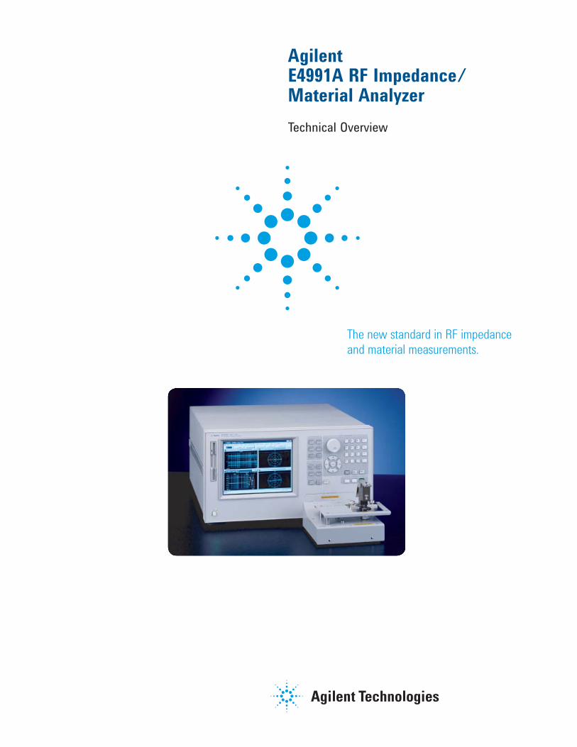
The new standard in RF impedance and material measurements.
Agilent E4991A RF Impedance/Material Analyzer
Technical Overview
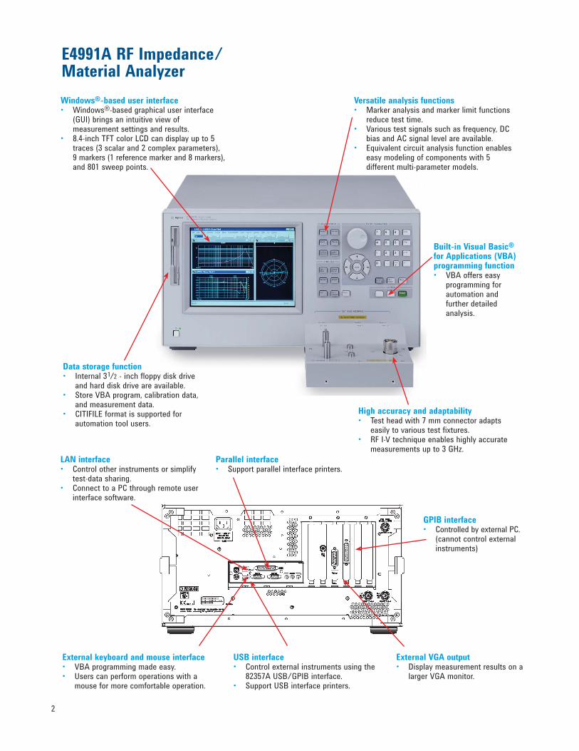
Windows®-based user interface • Windows®-based graphical user interface (GUI) brings an intuitive view of measurement settings and results.• 8.4-inch TFT color LCD can display up to 5 traces (3 scalar and 2 complex parameters), 9 markers (1 reference marker and 8 markers), and 801 sweep points.
High accuracy and adaptability• Test head with 7 mm connector adapts easily to various test fixtures.• RF I-V technique enables highly accurate measurements up to 3 GHz.
Versatile analysis functions • Marker analysis and marker limit functions reduce test time.• Various test signals such as frequency, DC bias and AC signal level are available.• Equivalent circuit analysis function enables easy modeling of components with 5 different multi-parameter models.
Built-in Visual Basic® for Applications (VBA) programming function • VBA offers easy programming for automation and further detailed analysis.
Data storage function • Internal 31/2 - inch floppy disk drive and hard disk drive are available.• Store VBA program, calibration data, and measurement data. • CITIFILE format is supported for automation tool users.
E4991A RF Impedance/Material Analyzer
2
External VGA output• Display measurement results on a larger VGA monitor.
Parallel interface• Support parallel interface printers.
External keyboard and mouse interface • VBA programming made easy. • Users can perform operations with a mouse for more comfortable operation.
LAN interface • Control other instruments or simplify test-data sharing.• Connect to a PC through remote user interface software.
GPIB interface• Controlled by external PC. (cannot control external instruments)
USB interface• Control external instruments using the 82357A USB/GPIB interface.• Support USB interface printers.
3
Powerful Analysis Functions to Meet Your Needs
The Agilent E4991A RF impedance/
material analyzer provides a total solu-
tion for making highly accurate, repeat-
able and stable measurements of surface
mount devices (SMD) and dielectric/
magnetic materials.
Recent trends indicate that wireless
communications and digital equipment
operating frequencies are getting higher,
while component sizes are getting small-
er. Component and equipment
manufacturing engineers need to evalu-
ate components they will be using in
their products under their projected
operating conditions. The E4991A can
evaluate passive component's charac-
teristics up to 3 GHz. Additionally, engi-
neers must measure SMDs as small as
0201(inch)/0603(mm).
Key Specifications
Agilent provides various test
fixtures for SMDs, designed to help
you obtain the impedance parameters
with high repeatability. The E4991A
offers impedance measurement capa-
bilities for your needs today and into
the future.
• Accurate and versatile 3 GHz
impedance measurement solution
• Analyze passive component
behavior
• Wide range of test fixtures
available
• PC connectivity features with
Windows®-based technology
Advanced Solution for RF Impedance and Material Measurement
The E4991A provides a powerful tool
for component manufacturing R&D
engineers and circuit designers of
wireless and digital equipment who
want to evaluate components from
various perspectives. The following
are application examples:
Passive components
• RF impedance measurement
of chip components such as
ceramic capacitors, RF inductors,
ferrite beads, and resistors
Semiconductors
• Capacitance-Voltage (C-V)
characteristics and Equivalent
Series Resistance (ESR)
measurements of varactor diodes
Materials
• Permittivity and loss tangent
evaluation of plastics, ceramics,
printed circuit boards and other
dielectric material
• Permeability and loss tangent
evaluation of ferrite, amorphous
and other magnetic materials
Table 1. E4991A key specifications
E4991A RF Impedance/Material Analyzer
Operating frequency 1 MHz to 3 GHz (1 mHz resolution)
Impedance parameters |Z|, θZ, |Y|, θY, R, X, G, B, CS, CP, LS, LP, RP, RS, D, Q, |Γ|, θΓ, ΓX, ΓY
Material parameters1 |εr|, εr’, εr", |μr|, μr’, μr", θ, tanδBasic impedance accuracy ±0.8%
Test port 7 mm connector
Sweep parameters Frequency, AC signal level, DC bias level
Calibration Open/short/50 Ω/low-loss capacitor
Fixture compensation Open/short, fixture electrical length
Mass storage 3 1/2 -inch floppy disk drive (MS-DOS® format), hard disk drive
Other features •Equivalent circuit analysis function
•Built-in VBA for internal programming
•Segment sweep
DC bias (Option E4991A-001)
DC level 0 V ~ ±40 V (1 mV resolution) 100 μA ~ 50 mA, –100 μA ~ –50 mA (10 μA resolution)
1. Option E4991A-002 is required
E4991A Provides New Insights into RF Passive Component Behavior
The Agilent E4991A's enhanced fre-
quency coverage up to 3 GHz is com-
patible with wireless
communication applications such
as W-CDMA, BluetoothTM, and
Wireless LAN. The E4991A’s wide
impedance coverage and versatile
measurement functions allow analysis
of RF chip inductors and capacitors
under actual operating conditions. A
wide range of test fixturing solutions
makes tiny chip device measurements
even easier.
Quality Factor (Q) and Equivalent
Series Resistance (ESR) are critical
parameters for the components used
in mobile communication equipment.
Q and ESR measurements require high
accuracy. Prior to the E4991A, there
was not a good solution available
over 2 GHz. The E4991A offers much
improved Q and ESR accuracy over
traditional network analyzers; due to
the enhanced
RF I-V technique that measures volt-
age and current at the device under
test (DUT), along with the innovative
low-loss capacitor
calibration.
Table 3 provides a brief summary of
the key differences between Agilent
E4991A and network
analyzers.
Low-loss capacitor calibration
The low-loss capacitor calibration of
the E4991A improves phase measure-
ment accuracy, which establishes a
reference to the reactance axis (-90
degrees) in the impedance plane with
its near-zero resistance. Capacitors
and inductors are measured close to
the reactance axis in
the impedance plane, making low-loss
capacitance calibration very effective
for ESR and Q measurements. (See
Figure 1)
Figure 1. Ls-Q characteristics of a chip inductor
Table 3. Comparison of key characteristics of E4991A and network analyzers
E4991A Network analyzers
Device type 1 port devices such as inductors, 2 port devices such as filters, capacitors, and others. amplifiers, and others.
Measurement |Z|, |Y|, θ, R, X, G, B, C, L, S-parameters, Γ, θparameters R, D, Q, ΓSweep • Frequency • Frequency parameter • Test signal level • Test signal levelsetting • DC bias voltage • DC bias current
Fixturing • Selection from various * Prepare custom test fixture or Agilent test fixtures use Agilent channel partner • Built-in fixture compensation solution function (Accuracy enhancement at DUT connection)
Impedance • Accurate high Q device • Accurate impedance measurement measurement due to low loss measurement around 50 Ωaccuracy capacitor calibration • Accurate measurement over non-50 Ω impedance
Other Equivalent circuit analysis function
Table 2. Q measurement accuracy (Typical)
4
5
In-depth Device Characterization
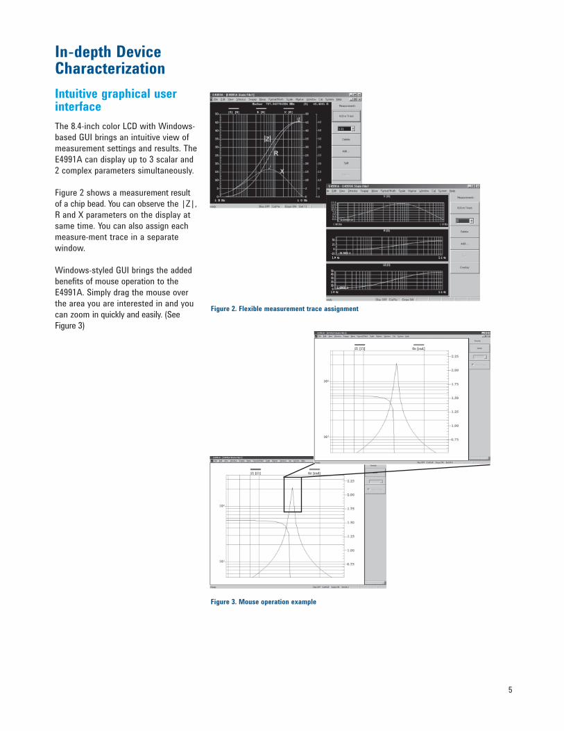
Intuitive graphical user interface
The 8.4-inch color LCD with Windows-
based GUI brings an intuitive view of
measurement settings and results. The
E4991A can display up to 3 scalar and
2 complex parameters simultaneously.
Figure 2 shows a measurement result
of a chip bead. You can observe the |Z|,
R and X parameters on the display at
same time. You can also assign each
measure-ment trace in a separate
window.
Windows-styled GUI brings the added
benefits of mouse operation to the
E4991A. Simply drag the mouse over
the area you are interested in and you
can zoom in quickly and easily. (See
Figure 3)
Figure 2. Flexible measurement trace assignment
Figure 3. Mouse operation example
6
DC bias function–Option E4991A-001
For components with voltage and
current dependency, such as RF
inductors or ceramic capacitors, the
DC bias function (Option E4991A-001)
supplies DC voltage (±40 V) and
current bias (±50 mA) across the
device. You can easily observe your
device behavior under various DC bias
conditions without using an external
DC bias source.
External DC bias adapter
If you require even higher DC current
bias, the Agilent 16200B external DC
bias adapter allows you to apply larger
DC bias across the device of up to
±5 mA through a 7 mm test port by
using an external DC current source.
E4991A operating frequency is limited
to 1 GHz with the 16200B.
Extracting the equivalent circuit parameters
The equivalent circuit analysis
function offers more detailed circuit
models over the standard 2-parameter
model. Five different multi-parameter
models accommodate different types
of devices, such as ceramic capacitors
or crystal resonators. You can simulate
the impedance trace of your own
equivalent parameter values and then
compare it with actual measurement
traces. The extracted parameters can
also be used with electronic design
automation (EDA) tools to improve
modeling accuracy.
Figure 4 shows the C-V characteris-
tic measurement of a varactor diode.
Sweeping DC voltage from 0.5 V to
4.5 V, you can easily read capacitance
change (11.27 pF) using the delta
marker function. Evaluate DC bias
voltage dependency on components
easily. DC current bias measurement
is also available so that you can eval-
uate characteristics of inductors, such
as, saturation or hysteresis. Figure 4. Varactor diode capacitance vs. DC voltage characteristics
Figure 5-1. 16200B
Figure 5. 16200B DC bias adapter connected to the E4991A
Figure 6. Equivalent circuit analysis models
7
Increase Productivity with Segment Sweep Function
The segment sweep function enables
different measurement setups in a
single sweep by dividing the sweep
range into segments. Each segment,
including the frequency range, number
of points, averaging factor, DC bias
level (V or I), and test signal level can
be set independently. (See Figure 7)
Segment sweep function can drasti-
cally reduce your test time when you
need specific data in a wide frequency
range. With segment sweep, you can
avoid repeatedly changing instrument
setups. (See Figure 7-1)
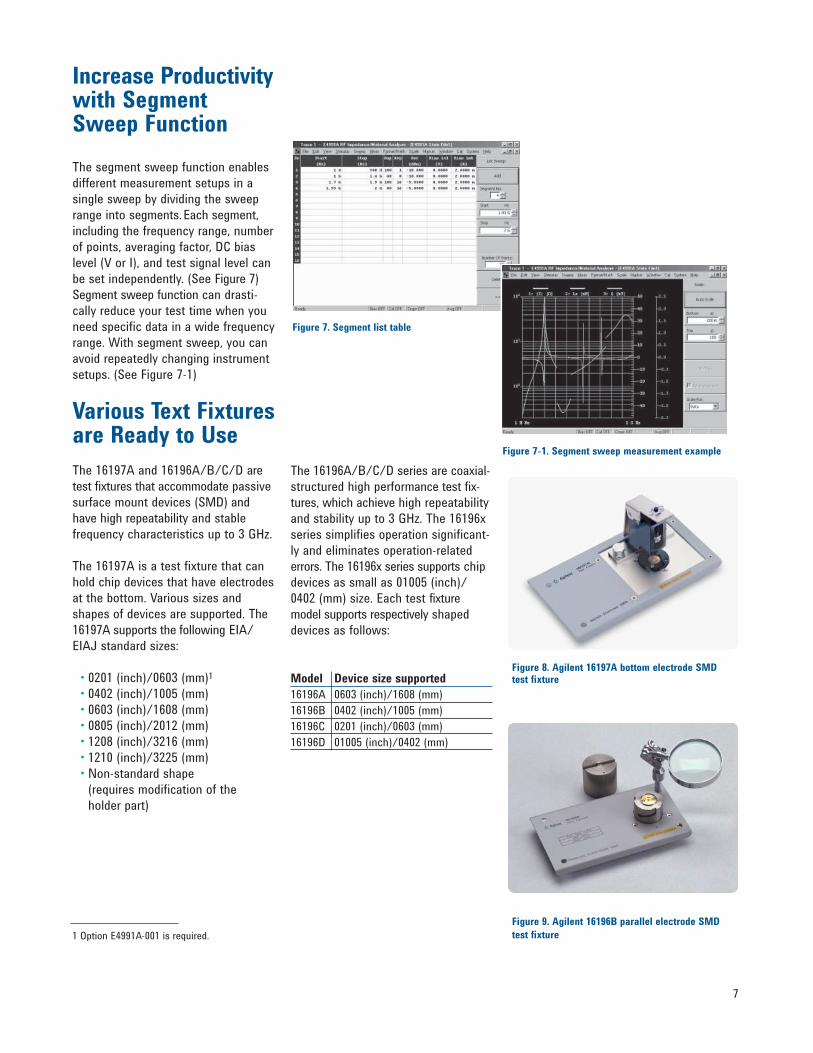
Various Text Fixtures are Ready to Use
The 16197A and 16196A/B/C/D are
test fixtures that accommodate passive
surface mount devices (SMD) and
have high repeatability and stable
frequency characteristics up to 3 GHz.
The 16197A is a test fixture that can
hold chip devices that have electrodes
at the bottom. Various sizes and
shapes of devices are supported. The
16197A supports the following EIA/
EIAJ standard sizes:
• 0201 (inch)/0603 (mm)1
• 0402 (inch)/1005 (mm)
• 0603 (inch)/1608 (mm)
• 0805 (inch)/2012 (mm)
• 1208 (inch)/3216 (mm)
• 1210 (inch)/3225 (mm)
• Non-standard shape
(requires modification of the
holder part)
The 16196A/B/C/D series are coaxial-
structured high performance test fix-
tures, which achieve high repeatability
and stability up to 3 GHz. The 16196x
series simplifies operation significant-
ly and eliminates operation-related
errors. The 16196x series supports chip
devices as small as 01005 (inch)/
0402 (mm) size. Each test fixture
model supports respectively shaped
devices as follows:
Model Device size supported
16196A 0603 (inch)/1608 (mm)
16196B 0402 (inch)/1005 (mm)
16196C 0201 (inch)/0603 (mm)
16196D 01005 (inch)/0402 (mm)
Figure 8. Agilent 16197A bottom electrode SMD test fixture
Figure 9. Agilent 16196B parallel electrode SMD
test fixture1 Option E4991A-001 is required.
Figure 7. Segment list table
Figure 7-1. Segment sweep measurement example
8
Connectivity Advances with PC and Windows-based Technology
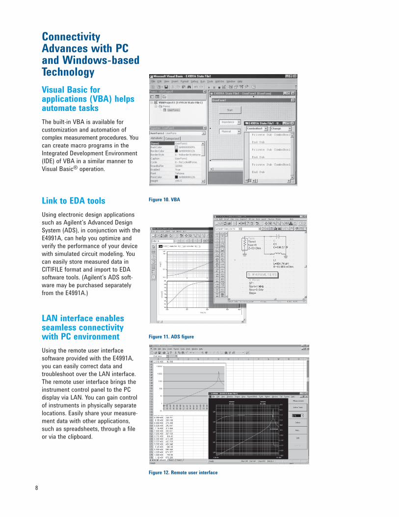
Visual Basic for applications (VBA) helps automate tasks
The built-in VBA is available for
customization and automation of
complex measurement procedures. You
can create macro programs in the
Integrated Development Environment
(IDE) of VBA in a similar manner to
Visual Basic® operation.
Link to EDA tools
Using electronic design applications
such as Agilent’s Advanced Design
System (ADS), in conjunction with the
E4991A, can help you optimize and
verify the performance of your device
with simulated circuit modeling. You
can easily store measured data in
CITIFILE format and import to EDA
software tools. (Agilent’s ADS soft-
ware may be purchased separately
from the E4991A.)
LAN interface enables seamless connectivity with PC environment
Using the remote user interface
software provided with the E4991A,
you can easily correct data and
troubleshoot over the LAN interface.
The remote user interface brings the
instrument control panel to the PC
display via LAN. You can gain control
of instruments in physically separate
locations. Easily share your measure-
ment data with other applications,
such as spreadsheets, through a file
or via the clipboard.
Figure 10. VBA
Figure 11. ADS figure
Figure 12. Remote user interface
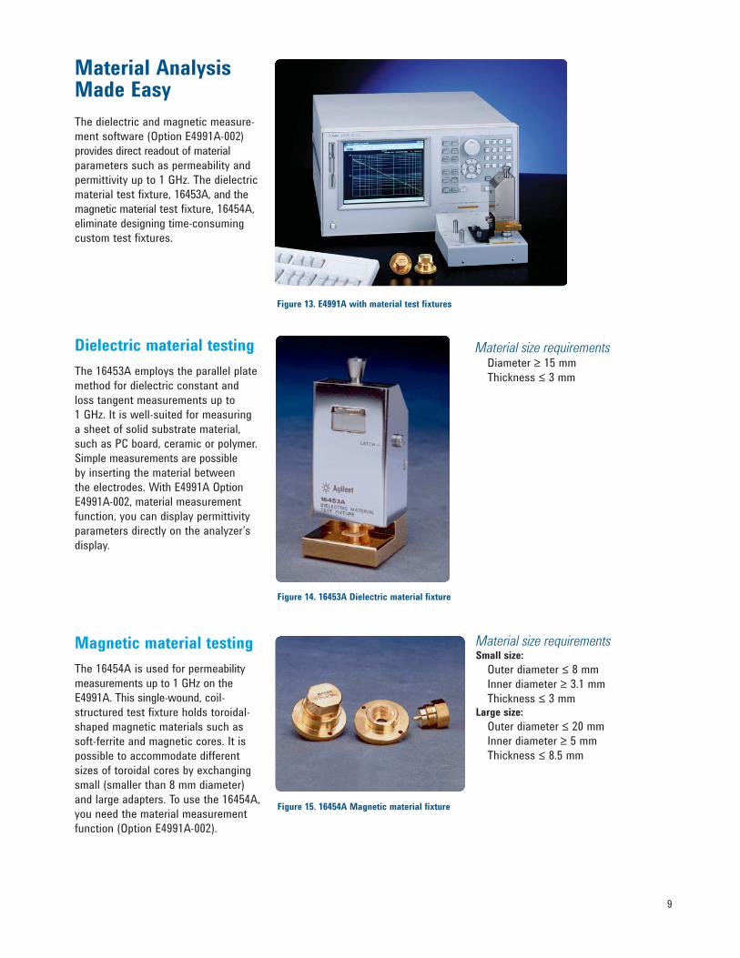
Material Analysis Made Easy
The dielectric and magnetic measure-
ment software (Option E4991A-002)
provides direct readout of material
parameters such as permeability and
permittivity up to 1 GHz. The dielectric
material test fixture, 16453A, and the
magnetic material test fixture, 16454A,
eliminate designing time-consuming
custom test fixtures.
Dielectric material testing
The 16453A employs the parallel plate
method for dielectric constant and
loss tangent measurements up to
1 GHz. It is well-suited for measuring
a sheet of solid substrate material,
such as PC board, ceramic or polymer.
Simple measurements are possible
by inserting the material between
the electrodes. With E4991A Option
E4991A-002, material measurement
function, you can display permittivity
parameters directly on the analyzer’s
display.
Magnetic material testing
The 16454A is used for permeability
measurements up to 1 GHz on the
E4991A. This single-wound, coil-
structured test fixture holds toroidal-
shaped magnetic materials such as
soft-ferrite and magnetic cores. It is
possible to accommodate different
sizes of toroidal cores by exchanging
small (smaller than 8 mm diameter)
and large adapters. To use the 16454A,
you need the material measurement
function (Option E4991A-002).
9
Material size requirements Diameter ≥ 15 mm
Thickness ≤ 3 mm
Material size requirementsSmall size:
Outer diameter ≤ 8 mm
Inner diameter ≥ 3.1 mm
Thickness ≤ 3 mmLarge size:
Outer diameter ≤ 20 mm
Inner diameter ≥ 5 mm
Thickness ≤ 8.5 mm
Figure 13. E4991A with material test fixtures
Figure 14. 16453A Dielectric material fixture
Figure 15. 16454A Magnetic material fixture
10
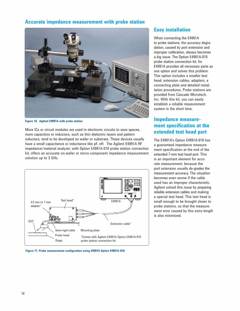
More ICs or circuit modules are used in electronic circuits to save spaces,
more capacitors or inductors, such as thin dielectric layers and pattern
inductors, tend to be developed on wafer or substrate. These devices usually
have a small capacitance or inductance like pF, nH. The Agilent E4991A RF
impedance/material analyzer, with Option E4991A-010 probe station connection
kit, offers an accurate on-wafer or micro-component impedance measurement
solution up to 3 GHz.
Easy installation
When connecting the E4991A
to probe stations, the accuracy degra-
dation, caused by port extension and
improper calibration, always becomes
a big issue. The Option E4991A-010
probe station connection kit, for
E4991A provides all necessary parts as
one option and solves this problem.
This option includes a smaller test
head, extension cables, adapters, a
connecting plate and detailed instal-
lation procedures. Probe stations are
provided from Cascade Microtech,
Inc. With this kit, you can easily
establish a reliable measurement
system in the short time.
Impedance measure-ment specification at the extended test head port
The E4991A’s Option E4991A-010 has
a guaranteed impedance measure-
ment specification at the end of the
extended 7-mm test head port. This
is an important element for accu-
rate measurement, because the
port extension usually de-grades the
measurement accuracy. The situation
becomes even worse if the cable
used has an improper characteristic.
Agilent solved this issue by preparing
reliable extension cables and making
a special test head. This test head is
small enough to be brought closer to
probe stations, so that the measure-
ment error caused by this extra length
is also minimized.
Figure 16. Agilent E4991A with probe station
Accurate impedance measurement with probe station
Figure 17. Probe measurement configuration using E4991A Option E4991A-010
Test head*
Extension cable*
E4991A
Mounting plate
3.5 mm to 7 mm
adapter*
*Comes with Agilent E4991A Option E4991A-010
probe station connection kit.
Semi-rigid cable
DUT
Probe head
Stage
11
Wide and repeatable impedance measurement
Agilent E4991A can cover wider
impedance range than network
analyzers. In general, network analyz-
ers are good at measuring impedance
near 50 Ω, but the accuracy gets
worse for impedance away from
50 Ω. The E4991A is designed to
measure non-50 Ω impedance as well,
so it can give much better accuracy
especially when you measure small
capacitance and inductance like 1 pF
and 1 nH. The E4991A is repeatable
over time and temperature, too This
is another benefit of dedicated imped-
ance analyzers.
Figure 18. Agilent E4991A Option E4991A-010 probe station connection kit
What is E4991A Option E4991A-010
The E4991A Option E4991A-010
includes following items:
• Smaller E4991A test head
• Extension cables
• 7 mm - 3.5 mm (f) adapter x 1 ea.
• N (m) - SMA (f) adapter x 3 ea.
• Installation manual
Probe
Agilent E4991A RF
impedance/material
analyzer
Probe headAgilent E4991A
probe station
connection kit
(Option E4991A-010)
What else do you need for a system?
Besides the E4991A with
Option E4991A-010, a probe station
and probe heads need to be pur-
chased separately. This option works
with any probe stations, but we
recommend Cascade Microtech probe
stations, because this combination
was carefully checked to work well.
The following are product examples:
• Summit 9000, 11000, or 12000
series probe station
• ACP-series or HPC-series probe
head
• Impedance Standard Substrate (ISS)
• Adjustable mounting plate for the
E4991A test head.
• Semi-rigid cable for the probe
head connection
These products are provided by
Cascade Microtech, Inc.
12
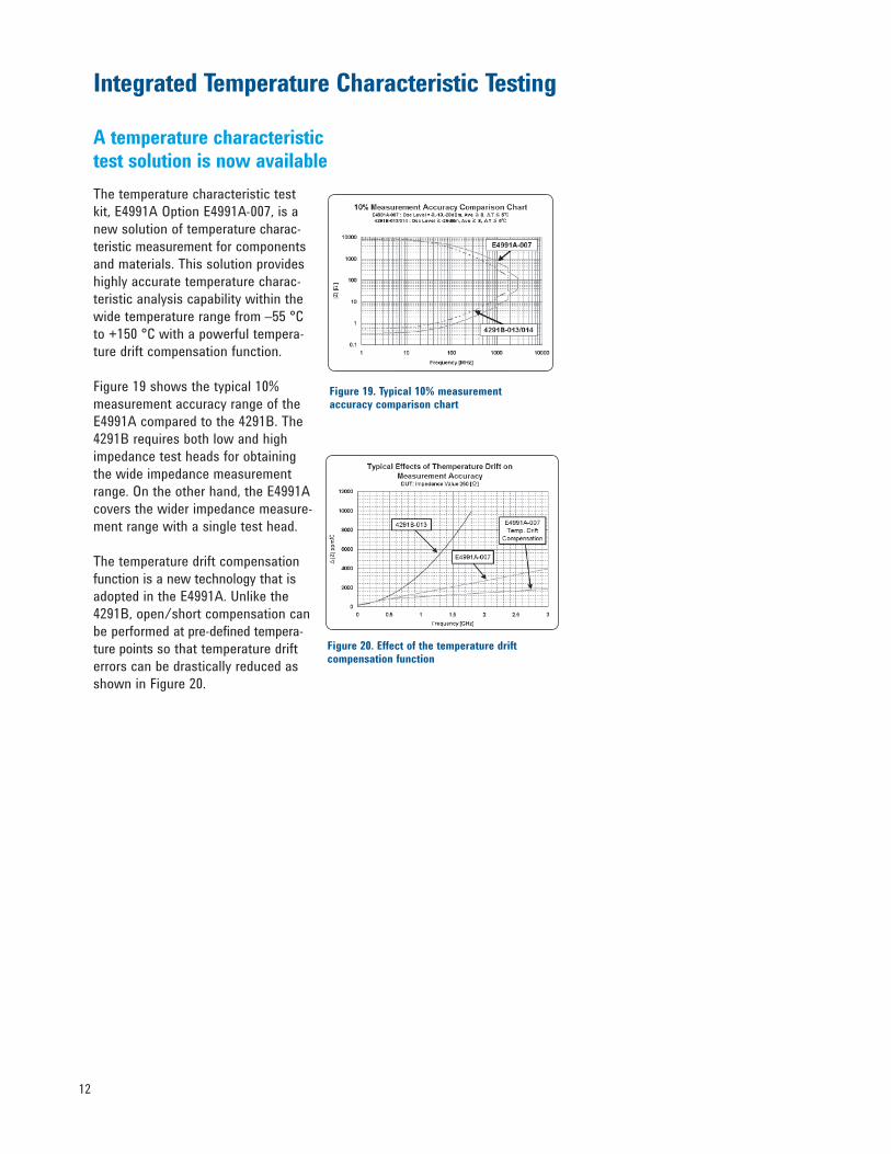
The temperature characteristic test
kit, E4991A Option E4991A-007, is a
new solution of temperature charac-
teristic measurement for components
and materials. This solution provides
highly accurate temperature charac-
teristic analysis capability within the
wide temperature range from –55 °C
to +150 °C with a powerful tempera-
ture drift compensation function.
Figure 19 shows the typical 10%
measurement accuracy range of the
E4991A compared to the 4291B. The
4291B requires both low and high
impedance test heads for obtaining
the wide impedance measurement
range. On the other hand, the E4991A
covers the wider impedance measure-
ment range with a single test head.
The temperature drift compensation
function is a new technology that is
adopted in the E4991A. Unlike the
4291B, open/short compensation can
be performed at pre-defined tempera-
ture points so that temperature drift
errors can be drastically reduced as
shown in Figure 20.
Figure 19. Typical 10% measurement accuracy comparison chart
Figure 20. Effect of the temperature drift compensation function
Integrated Temperature Characteristic Testing
A temperature characteristic test solution is now available
13
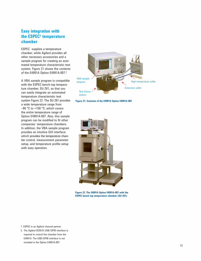
Figure 21. Contents of the E4991A Option E4991A-007
1. ESPEC is an Agilent channel partner.
2. The Agilent 82357A USB/GPIB interface is
required to control the chamber from the
E4991A. The USB/GPIB interface is not
included in the Option E4991A-007.
Figure 22. The E4991A Option E4991A-007 with the
ESPEC bench-top temperature chamber (SU-261)
Easy integration with the ESPEC1 temperature chamber
ESPEC supplies a temperature
chamber, while Agilent provides all
other necessary accessories and a
sample program for creating an auto-
mated temperature characteristic test
system. Figure 21 shows the contents
of the E4991A Option E4991A-007.2
A VBA sample program is compatible
with the ESPEC bench-top tempera-
ture chamber, SU-261, so that you
can easily integrate an automated
temperature characteristic test
system Figure 22. The SU-261 provides
a wide temperature range from
–60 °C to +150 °C; which covers
the entire temperature range of
Option E4991A-007. Also, this sample
program can be modified to fit other
companies’ temperature chambers.
In addition, the VBA sample program
provides an intuitive GUI interface;
which provides the temperature cham-
ber control, measurement parameter
setup, and temperature profile setup
with easy operation.
High-temperature cableVBA sample
program
Test fixture
station
Extension cable
14
Test Fixture Accessories
16197A bottom electrode SMD test fixture
Designed for bottom electrode SMDs up to 3 GHz. Adjustable
electrodes accommodate a wide array of sizes. This fixture is
designed to evaluate SMDs between 0.6 mm1 and 3.2 mm in
length.
Figure 23. 16197A
16196A/B/C/D parallel electrode SMD test fixture
Designed for side electrode SMDs up to 3 GHz. Dedicated design for specific shape of the devices eliminates repeatability errors and significantly improves usability. 0603 inch/1608 mm (16196A), 0402 inch/1005 mm (16196B), 0201 inch/0603 mm (16196C), and 01005 inch/0402 mm (16196D) are supported.
Figure 24. 16196A/B/C/D
16192A parallel electrode SMD test fixture
Holds chip devices with electrodes on both sides up to 2
GHz. Adjustable electrodes can accommodate a wide array
of sizes. This fixture is adapted to evaluate SMDs between
1.0 mm and 20.0 mm in length.
Figure 25. 16192A
16194A parallel electrode SMD test fixture
Holds both lead devices and SMDs up to 2 GHz.
It is furnished with two device holders that can
be easily attached to measure either type of DUT.
Figure 26. 16194A
SMD test fixture selection guide
Side Bottom DUT size electrodes SMD electrode SMD
01005 (inch)/0402 (mm) 16196D –
0201 (inch)/0603 (mm) 16196C 16197A3
0402 (inch)/1005 (mm) 16196B 16197A
0603 (inch)/1608 (mm) 16196A 16197A
0805 (inch)/2012 (mm) 16192A2 16197A
1206 (inch)/3216 (mm) 16192A2 16197A
1210 (inch)/3225 (mm) 16192A2 16197A
Over 1210 (inch)/3225 (mm) 16192A2 –
1. Option E4991A-001 is required.2. Frequency is limited to 2 GHz.3. Option 16197A-001.
15
Ordering information
Agilent E4991A RF impedance/
material analyzer includes:
Impedance test head, calibration kit
(50 Ω load, open, short, low loss
capacitor, torque wrench), power
cable, CD-ROM (firmware/VBA
software), and CD-ROM (manual).1
Configuration guide
Choose the option from the group <A>
depending on your requirement for
frequency reference function. Then,
choose the appropriate options from the
option group <B>, <C>, <D>, and <E>.
Choose ONE and ONLY one
(Options are mutually exclusive)
q Choose any combination
<A> For frequency reference function
E4991A-800 standard frequency
reference, no DC bias
E4991A-1D5 high stability
frequency reference
<B> For test function
q E4991A-001 DC bias
q E4991A-002 material
measurement firmware
q E4991A-007 temperature
characteristic test kit
q E4991A-010 probe station
connection kit
<C> For calibration certificate
q E4991A-1A7 ISO 17025
compliant calibration
<D> For accessories
q E4991A-810 keyboard
q E4991A-820 mouse
q E4991A-1CM rackmount kit
q E4991A-1CN front handle kit
q E4991A-1CP handle/rack
mount kit
<E> For manual2
q E4991A-ABA
U.S. - English localization
q E4991A-ABJ
Japan - Japanese localization
q E4991A-0BW service manual
Accessories3
16197A4 bottom electrode SMD test
fixture (up to 3 GHz)
Options
16197A-001 add 0201 (inch)/0603 (mm)
device guide set
16197A-ABA
U.S. - English localization
16197A-ABJ
Japan - Japanese localization
16196A/B/C/D5 parallel electrode
SMD test fixture (up to 3 GHz)
Options
16196A/B/C/D-710 add magnifying
lens and tweezers
16196A/B/C/D-ABJ
Japan - Japanese localization
16196A/B/C/D-ABA
U.S. - English localization
16196U maintenance kits for 16196X
Options
16196U-010 upper electrode set for
16196A/B/C (5 ea)
16196U-020 upper electrode set
for 16196D (5 ea)
16196U-100 1608 (mm) short
plate set (5 ea)
16196U-110 1608 (mm) lower
electrode set (5 ea)
16196U-200 1005 (mm) short
plate set (5 ea)
16196U-210 1005 (mm) lower
electrode set (5 ea)
16196U-300 0603 (mm) short
plate set (5 ea)
16196U-310 0603 (mm) lower
electrode set (5 ea)
16196U-400 0402 (mm) short
plate set (5 ea)
16196U-410 0402 (mm) lower
electrode set (5 ea)
16192A6 parallel electrode SMD test
fixture (DC to 2 GHz)
Options
16192A-701 short bars set
(1 x 1 x 2.4, 1.6 x 2.4 x 2,
3.2 x 2.4 x 2.4, 4.5 x 2.4 x 2.4) mm
16192A-710 add magnifying lens
and tweezers
16192A-010 EIA/EIAJ industry
sized short bar set
16094-65000 probe test fixture
(up to 125 MHz)
16453A dielectric material test fixture
(up to 1 GHz)
16454A magnetic material test fixture
(up to 1 GHz)
16190B performance kit
16195B 7 mm coaxial calibration kit
16092A SMD test fixture
(up to 500 MHz)
16200B external DC bias adapter
(up to 1 GHz)
82357B USB/GPIB Interface for
Windows7
1. Test fixtures, a keyboard, a mouse, USB/GPIB Interface, and a printed manual are not furnished as standard.2. Printed manual is not furnished as standard.3. Additional accessory details can be found in the Accessories Selection Guide for Impedance Measurements, publication number 5965-4792E.4. Must specify one of language options (ABA or ABJ) for operation manual for shipment with product.5. Magnify lens and tweezers are not furnished as standard. Must specify one of language options (ABA or ABJ) for operation manual for shipment with product.6. Short bar set, magnify lens, and tweezers are not furnished as standard. 7. The USB/GPIB Interface is required to control external devices.
E4991A Configuration and Accessory Guide
Web ResourcesPlease visit our component
manufacturer industry area at:
www.agilent.com/find/component_test
Please visit our impedance
solutions area at:
www.agilent.com/find/impedance
Windows® is a U.S. registered trademark of
Microsoft Corporation.
Visual Basic® for Applications is a U.S.
registered trademark of Microsoft Corporation.
BluetoothTM is a trademark owned by the
Bluetooth SIG, Inc.
For Cascade Microtech products,
contact Cascade Microtech, Inc.
Cascade Microtech
2430 NW 206th Avenue
Beaverton, Oregon 97006, U.S.A.
Tel. 503-610-1000
Fax. 506-601-1002
Email [email protected]
www.cascademicrotech.com
For the ESPEC products, contact
ESPEC Corp.
ESPEC CORP.
3-5-6, Tenjinbashi, Kita-ku, Osaka,
530-8550 Japan
Tel. +81-6-6358-4741
Fax. +81-6-6358-5500
www.espec.co.jp
ESPEC North America, Inc.
425 Gordon Industrial Court, S.W.
Byron Center, MI 49315-8354, U.S.A.
Tel. 616-878-0270
Toll Free 1-800-537-7320
Fax. 616-878-0280
www.espec.com
Remove all doubt
Our repair and calibration services
will get your equipment back to you,
performing like new, when prom-
ised. You will get full value out of
your Agilent equipment through-
out its lifetime. Your equipment
will be serviced by Agilent-trained
technicians using the latest factory
calibration procedures, automated
repair diagnostics and genuine parts.
You will always have the utmost
confi dence in your measurements.
For information regarding self main-
tenance of this product, please
contact your Agilent offi ce.
Agilent offers a wide range of ad-
ditional expert test and measure-
ment services for your equipment,
including initial start-up assistance,
onsite education and training, as
well as design, system integration,
and project management.
For more information on repair and
calibration services, go to:
www.agilent.com/fi nd/removealldoubt
Agilent Email Updates
www.agilent.com/fi nd/emailupdates
Get the latest information on the
products and applications you select.
Agilent Direct
www.agilent.com/fi nd/agilentdirect
Quickly choose and use your test
equipment solutions with confi dence.
For more information on Agilent Technolo-gies’ products, applications or services, please contact your local Agilent offi ce.
The complete list is available at:
www.agilent.com/fi nd/contactus
AmericasCanada (877) 894-4414 Latin America 305 269 7500United States (800) 829-4444
Asia Pacifi cAustralia 1 800 629 485China 800 810 0189Hong Kong 800 938 693India 1 800 112 929Japan 0120 (421) 345Korea 080 769 0800Malaysia 1 800 888 848Singapore 1 800 375 8100Taiwan 0800 047 866Thailand 1 800 226 008
Europe & Middle EastAustria 01 36027 71571Belgium 32 (0) 2 404 93 40 Denmark 45 70 13 15 15Finland 358 (0) 10 855 2100France 0825 010 700* *0.125 €/minute
Germany 07031 464 6333 Ireland 1890 924 204Israel 972-3-9288-504/544Italy 39 02 92 60 8484Netherlands 31 (0) 20 547 2111Spain 34 (91) 631 3300Sweden 0200-88 22 55Switzerland 0800 80 53 53United Kingdom 44 (0) 118 9276201Other European Countries: www.agilent.com/fi nd/contactusRevised: October 6, 2008
Product specifi cations and descriptions in this document subject to change without notice.
© Agilent Technologies, Inc. 2000, 2003, 2004, 2005, 2008Printed in USA, November 20, 20085980-1234E
www.agilent.com
www.agilent.com/fi nd/impedance
Recommended