Air Quality Monitoring Network Standard Operating Procedures for
Meteorological Sensors Confederated Tribes of the Colville Reservation
Prepared by Kris Ray
Air Quality Program Manager January 2012
2 -6 - 2-shyDate
APPROVED
2~ 7- 2shy
ampih~tolt Date
Quality Assurance Manager
Author
CTCR Meteorological SOP
Version 20 January 2012
ii
Table of Contents List of Tables iii
List of Figures iii
Introduction 1
Scope and Applicability 1
Health and Safety Warnings 1
Personnel QualificationsResponsibilities 2
Equipment 2
Procedures 2
BX-596 Air Temperature and Barometric Pressure Sensor 2
BX-592 Temperature Probe and Shield 3
Model 505 Wind Sensor 4
Model 083D Relative Humidity Temperature Sensor 8
Barometric Sensor 090D 9
Rain Gauge 375 001 Inches 10
Quality Control and Quality Assurance 11
Reference 12
Appendices 13
CTCR Meteorological SOP
Version 20 January 2012
iii
List of Tables Table 1 Meteorological Sensors and Components 1 Table 2 Wiring Connections between the BX-596 AT and BP Sensor and the BAM 1020
Terminal Strip 2 Table 3 BX-596 AT and BP Sensor Specifications 3 Table 4 Wiring Connections between the BX-592 AT Sensor and the BAM 1020 Terminal Strip4 Table 5 BX-952 Temperature Sensor and Shield Specifications 4 Table 6 Span Test Outputs for Blocked Transducers 7
Table 7 Model 505 Wind Sensor Specifications 7 Table 8 Model 083D RH and Temp Sensor Specifications 9 Table 9 Model 375C Rainfall Sensor Specifications 10 Table 10 Meteorological Sensor Quality Control and Assurance Measures 11
List of Figures Figure 1 Model 505 Wind Sensor Components 6 Figure 2 Model 073B Radiation Shield 9
Figure 3 Installing the Barometric Sensor 090D Wiring 10
1
Introduction This document provides the standard operation procedures (SOP) for meteorological (Met)
sensors at two monitoring sites within the exterior boundaries of the Colville Reservation Both
sites have a Beta Attenuation Monitor (BAM) model 1020 configured to measure particulate
matter (PM) 25 microns or smaller manufactured by Met One Instruments Inc The Met
sensors mentioned in this SOP support those monitors
Both monitors operate as Non-regulatory for comparison to the National Ambient Air Quality
Standards (NAAQS) Every effort will be made to assure that data gained by meteorological
sensors are rigorously controlled by the procedures set in this SOP
Scope and Applicability This SOP applies to the meteorological sensor portion of the monitoring network established
within the exterior boundaries of the Colville Reservation The two sites Nespelem and
Inchelium are equipped with sensors purchased at separate times 2005 and 2011 respectively
Table 1 provides specific information and serial numbers for each sensor at the two sites
Table 1 Meteorological Sensors and Components
Component Location
Nespelem Inchelium
BX-596 ATBP Sensor M5917
BX-592 Temperature Probe and Shield E5672
Model 505 Wind Sensor E6920 M4395
Model 505PS Heater Power Supply Yes Yes
Tower 10m Aluminum 18 Inch Base Yes Yes
Relative Humidity Sensor 083D-1-35 E6859
Barometric Sensor 090D (2632-1) E6799
Rain Gauge 375 001 Inches E5806
Health and Safety Warnings Safety precautions should be followed during the setup and operation of all meteorological
sensors Standard safety rules regarding electricity and power tools should be observed at all
time Installation of the 10 meter meteorological tower requires several precautions Follow
manufactures installation procedures for initial setup and reverse these if dissembling The tower
should be placed 2 times the height at a minimum away from hazards such as electric lines Plan
the process before beginning and coordinate with all involved Do not use metal ladders work
on wet or windy days Wear rubber soled shoes and other personal protective equipment
CTCR Meteorological SOP
Version 20 January 2012
2
Personnel QualificationsResponsibilities The quality assurance (QA) procedures detailed in this SOP require an understanding of all
meteorological sensors calibration protocol and normal operating processes EPA Guidance for
Quality Assurance Project Plans (US Environmental Protection Agency 2002) recommends
that all field operations personnel be familiar with environmental field measurement techniques
The Air Quality Program (AQP) encourages all personnel working with the sensors to read this
SOP and the individual documentation for each pieces of equipment
Equipment This SOP describes setup operation maintenance and quality control for all meteorological
sensors associated with the monitoring network The two sites have similar yet different sensor
models to accomplish the data gathering Table 1 list the sensors by location and provides serial
numbers where appropriate Manuals for all sensors are found in Appendices A ndash E at the end of
this SOP Many of the manuals can be downloaded from the Met One Inc website
httpwwwmetonecom All documents are kept on file in the AQP office and at each
monitoring site
Procedures Sensors will be inspected after receiving for shipping damage or other flaws If problems are
discovered the manufacture will be contacted for return or repair instructions
BX-596 Air Temperature and Barometric Pressure Sensor The BX-596 combination ambient temperature (AT) and barometric pressure (BP) sensor is a
required accessory for all Federal Equivalent Method (FEM) BAM 1020 configured to sample
PM25 levels The sensor provides ambient temperature and pressure data to the unit for actual
flow control and flow statistics during the hourly sample cycle The BX-596 is only compatible
with BAM 1020 firmware version 324 or later Attach the sensor to the sample tube using the
hardware provided and rout the cable into the cabinet Follow the wiring pairing as shown in
Table 2 when connecting to the back of the BAM 1020 on channel 6 when the monitor is turned
off The BAM will automatically detect the ID voltage and configure input channels six and
seven to read and scale the outputs from the sensor Table 3 provides specifications for the
combination sensor
Table 2 Wiring Connections between the BX-596 AT and BP Sensor and the BAM 1020 Terminal Strip
BX-596 ATBP Sensor
Wire Color Terminal Name
Yellow Channel 6 SIG
BlackShield Channel 6 COM
Red Channel 6 Power
Green Channel 6 ID
White Channel 7 SIG
CTCR Meteorological SOP
Version 20 January 2012
3
Table 3 BX-596 AT and BP Sensor Specifications
BX-596 Barometric Pressure Ambient Temperature
Voltage Output 0 to 25 volts 0 to 25 volts
Range 525 to 825 mmHg -40 to +55 degrees C
Accuracy plusmn 025 mmHg at 25˚ C plusmn 15˚ C above -30˚
ID Voltage 410 volts DC plusmn 002
After installing the sensor a flow calibration is performed following the instructions in the Air
Quality Monitoring Network Standard Operating Procedures for BAM 1020 PM 25 Monitors
The AT and BP can be adjusted in the STD column based on the reference standard
measurements The Default hot key can be pressed to reset the user calibration from the selected
parameter and replace it with a factory setting if values appear to deviate from expected
The BX-596 temperature output may also be checked in an ice bath The ice bath test is usually
never done except in some cold weather environments First calibrate the sensor at ambient
temperature and then use the following steps
1 Remove the stop screw from the bottom of the mounting bracket so that the electronics
module is free to rotate Rotate the module counter-clockwise until it disengages from the
keyhole slots and comes free from the radiation shield
2 The sensor comes with an 18 inch long ice bath extension harness This may be used to allow
the temperature bead to reach the ice bath if necessary Carefully unplug the black
temperature bead assembly from the top of the electronics module and install the harness
between the bead and the module
3 Insert the temperature bead into the ice water bath along with your reference sensor Avoid
immersing the bead assembly past the connector
4 Allow the bead to equilibrate then compare the AT reading in the TESTgt FLOW screen to
your reference sensor The tolerance for the regular BX-596 standard range sensor is plusmn 25 C
in temperatures below -30C
5 Remove the ice bath harness and reassemble the sensor
During operation of the BAM-1020 the output from the BX-596 can be viewed from the main
flow statistics screen or the OPERATE screens
Simple maintenance practices will keep the BX-596 operational which include
1 Make sure the four holes in the cover plate are clear by removing the bottom cover for
inspection
2 Clean the radiation shield assembly once each year
3 The black temperature bead assembly may be replaced if the bead becomes damaged The
assembly simply plugs into the top of the electronics module The sensor will need to be
recalibrated any time the temperature bead is replaced
4 The circuit board can only be serviced by the manufacture
BX-592 Temperature Probe and Shield This sensor provides temperature measurement of the outside air used to determine the
correction value as part of the volumetric flow calculation The sensor is designed to be
connected directly to one of the analog input channels of the BAM1020 The sensor comes with
CTCR Meteorological SOP
Version 20 January 2012
4
30 feet of cable and mounting hardware The sensor is mounted on the sample tube below the
PM10 and Sharp Cut Cyclone (SCC) air intakes The cable entry into the enclosure can be by a
weather tight hole in the top or side
Connect the cable onto the channel 6 location on the back of the BAM 1020 following the
pairing in Table 2 Table 3 provides specifications for the temperature sensor
Table 4 Wiring Connections between the BX-592 AT Sensor and the BAM 1020 Terminal Strip
BX-592 AT Sensor
Wire Color Terminal Name
Yellow or White Channel 6 SIG
BlackShield Channel 6 COM
Red Channel 6 Power
Green Channel 6 ID
The sensor shield provides protection for the temperature probe from direct solar radiation The
shape allows for the wind to naturally aspirate the shield to reduce the total effect of solar
radiation on the temperature measurement
Table 5 BX-952 Temperature Sensor and Shield Specifications
Temperature Probe Type
Thermistor Bead multi-element
Temperature Accuracy plusmn 002˚ degrees C
Temperature Range -30˚ C to + 50˚ C
Sensor Output
0 to 1 VDC for temperature range
Time Constant
10 Seconds in still air
Maintenance and calibration of the BX-592 consists of simple procedures recommended by Met
One Inc Maintenance includes cleaning the radiation shield once each year to prevent buildup
of material that would alter or decrease the reflectivity Temperatures are checked andor
adjusted during the flow verification process of the BAM 1020 as outlined in the monitoring
network SOP The temperature probe is not adjustable in the field and should only be repaired
by the manufacturer
Model 505 Wind Sensor The 505 Wind Sensors are a solid-state ultrasonic instrument capable of measuring wind speed
and wind direction in the U and V axes Sonic pulses are generated at the transducers and are
received by opposing transducers Mathematics derived for these sonic pulses provide a wind
velocity measurement in each of the corresponding axes
CTCR Meteorological SOP
Version 20 January 2012
5
The 505 uses a microprocessor-based digital electronic measurement system to control the
sample rate and compute the wind speed and wind direction The sensor is factory calibrated and
requires no field calibration In the field the operation of the sensor can be quickly checked
using a combination of simple tests A zero chamber or bag is used to verify the zero reference
by covering the entire sensor or individual outputs are checked by blocking various
combinations of sensors
The sensor is designed for installation in a Model 3188 mounting and alignment fixture (Figure
1) This provides a mount for use on a horizontal frac34 inch IPS pipe boom The 3188 Sensor
Mounting Fixture includes a keyed bushing which will be adjusted for alignment to North
orientation enabling the sensor to be removed and replaced without realignment Three captive
machine screws are used to secure the sensor to the keyed bushing Review page 22 of the
operation manual (Appendix C) for a diagram of a top of tower installation
Orientation of the sensor to true north can be accomplished by following the instruction on page
8 of the operation manual and should be necessary only on setup To prevent birds from
perching on the sensors stainless steel wire deterrents are installed prior to securing to the
alignment fixture Safety precautions should be followed during this operation because the
deterrents are very sharp
The External Heater provides de-icing for the sensor arms and prevents the accumulation of ice
which might block the sonic elements The heater consists of a laminated material that is
wrapped around the four sensor arms and sonic sensor element housings Heater power is
supplied from a Met One Instruments power unit in a weatherproof box The heater is activated
at 38 degrees F and will keep the arms ice-free at temperatures down to below -20 degrees F
The connection information can be found in Appendix C of this manual
The temperature controller electronics box should be mounted no more than 5 feet from the
sensor using the U-bolts and cable supplied with the heater controller A two conductor cable
spans the distance from the heater controller to the heater power supply The power supply
fastened to the tower with the U-bolts provided and then plugs into a three prong 120 volt AC
receptacle
Follow the instructions on page 12 of the operations manual for details on connecting the data
cable to the data logger Several options are available depending on which connection is needed
The data cable from the sensor to the data logger should be secured to the boom and tower with
cable ties The two wind sensors differ in voltage output 0 to 25 volts at Nespelem and 0 to 10
volt at Inchelium This difference is important when configuring the data loggers at each site
Operation of the 505 is essentially automatic no specific sensor calibration is required The
sensor has been calibrated in a wind tunnel at the factory prior to shipment The sealed sensor
cannot be adjusted in the field and there are no replaceable parts To ensure that the recorder is
scaled properly the manufacture recommends that zero and span tests are performed after the
sensor is connected and operational
CTCR Meteorological SOP
Version 20 January 2012
6
Figure 1 Model 505 Wind Sensor Components
CTCR Meteorological SOP
Version 20 January 2012
7
A zero test requires the prevention of air movement across the sensor by covering the array A
plastic bag can be placed over the array using care not to contact the transducers or block the
sonic paths between transducers The bag should be spaced at least 2 above the transducers to
avoid sonic reflections which may affect readings The bag can be tied at the bottom with a tie
wrap or tape to prevent air movement from below the wind can deflect the bag causing air
movement inside With no air movement across the array the sensor should indicate 00 to 01
ms wind speed The wind direction output will wander to any value between 0 and 360 degrees
The sensor is designed to produce known default outputs if an object blocks the sonic signal path
between the transducers This feature is useful for verifying sensor operation and recorder
scaling For testing purposes the sonic path can be blocked by placing a finger (or any solid
object) on the face of one or more transducers
The outputs after blocking the transducers are shown in Table 6 below
Table 6 Span Test Outputs for Blocked Transducers
Wind Speed
Blocked Axis Serial Output Analog Output 0-10 V 0-25 V
North-South 100 ms 50 ms 100 V 250 V
East-West 100 ms 50 ms 100 V 250 V
Both 100 ms 50 ms 100 V 250 V
Wind Direction
Blocked Axis Serial Output Analog Output 0-10 V 0-25 V
North-South 10 degrees 10 degrees 003 V 007 V
East-West 160 degrees 160 degrees 044 V 111 V
Both 170 degrees 170 degrees 047 V 118 V
The testing of the transducers can easily be accomplished when the tower is tipped down for the
yearly inspection Table 7 lists the specifications for the wind sensor
Table 7 Model 505 Wind Sensor Specifications
Wind Speed Specifications
Range 0 to 50 msec
Accuracy plusmn 02 msec le 113 msec or plusmn 2 ge113 msec
Resolution 01 msec
Wind Direction
Range 0 to 360deg
Accuracy plusmn3deg
Resolution 1˚
CTCR Meteorological SOP
Version 20 January 2012
8
Operation
Sample Rate 5 per second
Data Output Rate 1 per second
Sonic frequency 200 KHz
Output Signals
Wind speed voltage 0-50 VDC
Wind direction voltage 0-50 VDC
RS-232 1200 to 192K Baud
Power requirement
Sensor 9-18 VDC 10 mA 12 VDC Average power
External Heater Option 15 VDC 50 Watts
Environmental
Maximum Measurement range 0 to 65 mls
Operating Temperature -40degC to +55degC no ice
Extended Temperature Range -50degC to +55degC with external heater
Physical
Weight 55 Ibs
Dimensions 1929in high 938in diameter
Model 083D Relative Humidity Temperature Sensor
The 083D-1-35 Sensor is an extremely accurate and sensitive relative humidity and temperature
sensor Response is linear with small hysteresis and negligible temperature dependence The
sensors are installed in a radiation shield before shipping The 73B radiation shield (Figure 2)
mounts on the opposite end of the boom from the 505 wind sensor on top the tower The
radiation Shields and cables have Mil Spec screw-on or twist-on cable connectors that are pre-
fitted by Met One The cable should be secured to the boom and tower with cable ties
The Relative HumidityTemperature Sensor has been calibrated at the factory and will not
change unless it is damaged Blow on the sensor for a quick check for operation the RH will
rise To check for reasonableness of operation compare the measurement with a local weather
service facility The reading will not be exactly the same but should be similar Compare the
temperature measurement to the delta Cal standard reading when conducting flow verifications
The sensor may need cleaning due to the accumulation of dust or other substances that will affect
measurements Turn off power to the sensor before attempting to clean and keep off until dry
Cleaning with distilled water will be adequate in most instances If extremely dirty or covered
with substance water will not remove isopropanol can be used Follow the instruction in the
operations manual to prevent damage to the sensor when cleaning with liquids
CTCR Meteorological SOP
Version 20 January 2012
9
Figure 2 Model 073B Radiation Shield
Table 8 Model 083D RH and Temp Sensor Specifications
Sensing Element Thin-film Capacitor
RH Range 0 - 100
Temp Range -50deg to +50degC
Response Time 15 seconds at 20degC
RH Accuracy plusmn2 RH between 10 and 100 RH
Temp Accuracy 01degC
Hysteresis For 0 to 100 to 0 excursion le 1
Temperature Coefficient plusmn004 per 1degC
Output 0 - 1 V full scale
Input Power 12V DC
Barometric Sensor 090D
The 090D (2632-1) uses an active solid-state device to sense barometric pressure with a range of
26 to 32 inches of mercury and a voltage output of 0 ndash 1 volt The sensor attaches to the tower or
other convenient location with a ldquoJrdquo bolt Orient the J box with the pressure inlet port facing
down Install the cable through the water tight fitting and connect as shown in Figure 2
CTCR Meteorological SOP
Version 20 January 2012
10
Figure 3 Installing the Barometric Sensor 090D Wiring
The sensor has been calibrated at the factory and will not change unless damaged No field
modification or calibrations can occur To check for proper operation compare to a local
weather station to see if the readings are reasonable The measurement will not be exactly the
same due to differences in elevation and measurement parameter absolute or normalized to sea
level This sensor measures absolute inches of mercury BP can also be checked when
conducting regular flow verifications or calibrations on the BAM 1020 The deltaCal standard
measures BP as millimeter (mm) or millibars (mb) and can be converted to inches mercury by
multiplying mm X 03937 and mb X 00295
Maintenance consists of inspecting the pressure inlet port for blockages and removing
obstructions if found If service or recalibration becomes necessary then send the sensor to the
manufacture
Rain Gauge 375 001 Inches This sensor measures precipitation on a continuous basis and is low-maintenance The tipping
bucket collects 001 inches of precipitation then tips and drains This triggers a switch closure
pulse that is counted The tipping bucket and rain gauge are heated to prevent accumulation of
snow and ice The sensor has been calibrated at the manufacture and should not require
adjustments after installation Mount the sensor level on a platform using the built in level and
three adjusting legs Follow the instruction in the operations manual (Appendix F) for complete
installation instructions A debris screen should be removed during the winter when snow will
accumulate
After installation manually actuate the tip bucket mechanism three times and confirm the tips
have registered on the data logger Inspect and clean the tipping buckets periodically and
physically tip to verify recording on the data logger If the sensor has been damaged or appears
to need calibration follow the instruction in the operations manual
Table 9 Model 375C Rainfall Sensor Specifications
Orifice 8 Inch Diameter
Calibration 01 Inches Rain per Switch Closure
Accuracy plusmn 1 at 1 to 3 inches per hour at 70 Fdeg
Switch Type Magnet and Reed
Mounting 3 Pad for 14 inch bolts
Dimensions 8 Inch Diameter
CTCR Meteorological SOP
Version 20 January 2012
11
Power Requirement 110 VAC
Weight 75 Pounds
Quality Control and Quality Assurance Quality Control (QC) and Quality Assurance measure are minimal due to the reliability and low
maintenance of the meteorological sensors employed The following table list all standards
used maintenance needed and actions If sensors exhibit characteristics outside of these
parameters the manufacturer will be contacted for instructions Records related to Meteorological
sensors will be tracked on the site log and summaries semiannually
Table 10 Meteorological Sensor Quality Control and Assurance Measures
Sensor Criteria Action
BX-596 ATBP Sensor
BP varies more than plusmn10 mm Hg from deltaCal Standard BAM 1020 Calibration Following SOP
Temperature varies more than plusmn2degC from deltaCal Standard BAM 1020 Calibration Following SOP
Sensor shield andor probe damaged Contact Met One for instructions
BX-592 Outside Temperature Sensor Volumetric Flow
Temperature varies more than plusmn2degC from deltaCal Standard BAM 1020 Calibration Following SOP
Temperature shield andor probe damaged Contact Met One for instructions
Model 505 Wind Sensor
Yearly zero test reading 00 to 01 ms wind speed
Contact Met One for instructions if greater than these readings
Yearly span test
Contact Met One for instructions if readings do not match those shown in Table 6
Heater not functioning Contact Met One for instructions
Relative HumidityTemperature
Sensor 083D
Yearly check for reasonableness Compare with local weather station
Yearly check for operation Blow on sensor and confirm RH rise
Barometric Sensor 090D Yearly inspection
Clean pressure inlet port for blockages when needed
Compare to deltaCal Standard Contact Met One for instructions if values do not compare reasonably
Rain Gauge 375 001 Inches
Yearly check for operation Manually tip bucket and confirm reading
Yearly check for level Use adjustment legs to level
Damage or bucket set screws loose
Follow instructions in operation manual for calibration
CTCR Meteorological SOP
Version 20 January 2012
12
Reference EPA Requirements for Quality Assurance Project Plans EPA QAR-5 Office of Environmental
Information Washington DC EPA240B-01003 March 2001
Guidance for Quality Assurance Project Plans EPA QAG5 Office of Environmental
Information Washington DC EPA240R-02009 December 2002
Guidance for Preparing Standard Operating Procedures (SOPs) EPA QAG-6 Office of
Environmental Information Washington DC EPA6000B-07001 April 2007
Met One Instruments Inc (2008) BAM 1020 particulate monitor operation manual Prepared by
Met One Instruments Inc Grants Pass OR BAM-1020-9800 Rev G
Standard Operating Procedure for the Continuous Measurement of Particulate Matter Monitoring
Sites Confederated Tribes of the Colville Reservation Air Quality Program August 2011
CTCR Meteorological SOP
Version 20 January 2012
13
Appendices
BX-596 ATBP SENSOR MANUAL
Met One Instruments Inc 1600 Washington Blvd Grants Pass Oregon 97526 Telephone 541-471-7111 Facsimile 541-541-7116
BX-S9G Sensor Manual - copy Copyright 2007 Met One Instruments Inc All Rights Reserved worldwide No part of this publication may be reproduced transmitted transcribed stored in a retrieval system or translated into any other language in any form without the express written permission of Met One Instruments Inc
Appendix A BX-596 ATBP Sensor Operation Manual
About this Manual
The BX-596 is an optional combination ambient temperature and barometric pressure sensor for use with the BAM-1020 particulate monitor The BX-596 sensor is a required accessory for all BAM-1020 configured to sample PM25 levels effective March 2007 The sensor provides ambient temperature and pressure data to the unit for actual (volumetric) flow control and flow statistics during the hourly sample cycle The BX-596 is only compatible with BAM-1020 firmware version 324 or later This manual describes the installation and operation of the BXshy596 sensor Refer to the BAM-1020 operation manual as needed
The BX-596-1 is an extended range version for extreme cold or high altitude environments
BX-59G TemperaturePressure Sensor Installed on a BAM-1020 Inlet Tube
Specifications
I
I I
I
I
I I
BX-59G Barometric Pressure Ambient Temperature Voltage Output o to 25 volts o to 25 volts
Range 525 to 825 mmHg -40 to +55 deg C Accuracy plusmn025 mmHg 25 C plusmn 15C above -30
10 Voltage 350 volts DC plusmn 02
BX-59G-1 Barometric Pressure Ambient Temperature i
Voltage Output o to 25 volts o to 25 volts Range 400 to 825 mmHg -50 to +50 deg C
Accuracy plusmn15 mmHg plusmn 15C full scale 10 Voltage 410 volts DC plusmn 02
BX-596-98DD Manua RevBdoc Page 1 of 4
Appendix A BX-596 ATBP Sensor Operation Manual
Installation and Setup
Ensure that the BAM-1020 is sited and installed properly per the instructions in the operation manual
During the installation process you will need to provide an access point for the BX-596 sensor cable to enter the shelter where the BAM-1020 is installed In some cases it is easiest to simply drill a 38 hole through the roof of the shelter about six inches away from the inlet tube then feed the cable through the hole and caulk around it to prevent leaks
There may be a better place to feed the cable into the shelter in some applications The BXshy902903 environmental shelters supplied by Met One have pre-formed access holes in the side to allow the sensor cable to be routed to the BAM-1020 Decide the best way to route the cable into the shelter The BX-596 comes with a standard 25-foot sensor cable Longer cables may be ordered if required
Remove the PM 10 head and PM25 cyclone from the top of the BAM inlet tube Attach the BXshy596 to the inlet tube (about 8 to 18 inches from the top) with the supplied U-bolt hardware Make sure that the sensor is level and tighten the U-bolt securely
Make sure the BAM-1020 is turned off then attach the sensor cable to the connector on the bottom of the BX-596 Route the loose end of the cable into the shelter and to the back of the BAM-1020 Coil up any excess length of cable Attach the cable to the back of the BAM as shown in the following table
I
BX596 ATBP Sensor Connections Wire Color Function BAM Terminal
Yellow A T Signal Output Channel 6 SIG BlackShield Ground Channel 6 COM Red +12 VDC Channel 6 POWER Green Auto 10 Signal 350V Channel 6 10 White BP Signal Output Channel 7 SIG
Reinstall the PM10 head and PM25 cyclone and seal around the cable hole with silicone if required
Operation
When the BAM-1020 is powered up with a BX-596 installed the unit will automatically sense the 10 voltage from the sensor and configure input channels six and seven to read and scale the outputs from the sensor Note The BX-596 sensor requires BAM-1020 firmware revision 320 or later The BX-596-1 extended range version requires BAM-1020 firmware revision 362 or later If the BAM firmware is not current enough then the BAM will not automatically identify and scale the sensor
Appendix A BX-596 ATBP Sensor Operation Manual
Turn ON the BAM-1020 and perform a calibration of the BX-596 Note The calibration is performed in the TESTgt FLOW screen which will not be available unless the FLOW TYPE is set to ACTUAL in the SETUPgt CALIBRATE screen You will need a reference standard measurement for ambient temperature and barometric pressure
MULTIPOINT FLOW CALIBRATION TARGET BAM STD
ltCALgt ~~~ 238 238 C BP 760 760 mmHg
FLOW 1 150 150 150 LPM FLOW 2 183 183 183 LPM FLOW 3 167 167 167 LPM
CAL NEXT DEFAULT EXIT
1 Enter the TESTgt FLOW menu as shown above The nozzle will lower automatically when this screen is entered The BAM colurnn is what the BAM-1020 measures for each parameter and the STO column is where you will enter the correct values from your reference standard The ltCALgt symbol will appear next to the parameter selected for calibration
2 Measure the ambient temperature with your reference standard positioned near the BXshy596 sensor Enter the value from your reference standard into the STO field using the arrow keys Press the CAL hot key to correct the BAM reading The BAM and STO values should now be the same
3 Press the NEXT hot key to move the ltCALgt indicator to the BP field and repeat the same steps for barometric pressure
The DEFAULT hot key can be pressed to reset the user calibration from the selected parameter and replace it with a factory setting The DEFAULT calibration should be fairly close in most cases
The BX-596 sensor is almost always calibrated as part of a BAM-1020 flow calibration Always calibrate the AT and BP channels before calibrating the flow channels as the flow rate is affected by the temperature and pressure of the ambient air
The 8X-596 temperature output may also be checked in an ice bath The ice bath test is usually never done except in some cold weather environments First calibrate the sensor at ambient temperature then use the following steps
1 Remove the stop screw from the bottom of the mounting bracket so that the electronics module is free to rotate Rotate the module counter-clockwise until it disengages from the keyhole slots and comes free from the radiation shield
2 The sensor comes with an 18 inch long ice bath extension harness This may be used to allow the temperature bead to reach the ice bath if necessary Carefully unplug the black temperature bead assembly from the top of the electronics module and install the harness between the bead and the module
3 Insert the temperature bead into the ice water bath along with your reference sensor Avoid immersing the bead assembly past the connector
Appendix A BX-596 ATBP Sensor Operation Manual
4 Allow the bead to equilibrate then compare the AT reading in the TESTgt FLOW screen to your reference sensor The readings should match within plusmn15 degrees C for the BXshy596-1 extended range sensor Note The tolerance for the regular BX-596 standard range sensor is plusmn 25 C in temperatures below -30C
5 Remove the ice bath harness and reassemble the sensor
During operation of the BAM-1020 the output from the BX-596 can be viewed from the main flow statistics screen or the OPERATE screens See the BAM-1020 manual
JI -~J
1 1~
i gt
-- --- shyv_
Ice Bath Extension Harness
Maintenance The BX-596 is designed to be low-maintenance easy to access and resistant to harsh environments There are only a few maintenance items for the sensor besides routine calibration checks
bull Remove the bottom cover and make sure that the four holes in the cover plate are clear and have not been obstructed by insects or debris These holes allow the air pressure to equilibrate inside the sensor for the barometric pressure reading Clean the inside of the electronics enclosure every 12 months or as needed
bull Clean the radiation shield assembly at least once per year Dirty shields reflect away solar radiation less efficiently
bull The circuit board is not intended to be removed or serviced by the customer bull The black temperature bead assembly may be replaced if the bead becomes damaged
The assembly simply plugs into the top of the electronics module The sensor will need to be recalibrated any time the temperature bead is replaced
Technical Support
Should you still require support after consulting your printed documentation we encourage you to contact one of our expert Technical Service representatives during normal business hours of 700 am to 400 pm Pacific Standard Time Monday through Friday In addition technical information and service bulletins are often posted on our website Please contact us and obtain a Return Authorization (RA) number before sending any equipment back to the factory This allows us to track and schedule service work and expedite customer service
Phone (541)471-7111 Fax (541)471-7116 E-Mail servicemetonecom Web wwwmetonecom
Mail Technical Services Department Met One Instruments Inc 1600 NW Washington Blvd Grants Pass OR 97526
Appendix A BX-596 ATBP Sensor Operation Manual
warranty
Products manufactured by Met One Instruments Inc are warranted against defects in material and workmanship for a period of one (1) year from the date of shipment from the factory Offered products not manufactured by Met One Instruments Inc will be warranted to the extent and in the manner warranted by the manufacturer of that product
Any product found to be defective during the warranty period will at the option of Met One Instruments Inc be replaced or repaired In no case shall the liability of Met One Instruments Inc exceed the purchase price of the product
This warranty may not apply to products that have been subject to misuse negligence accident acts of nature or that have been altered or modified other than by Met One Instruments Inc Consumable items such as bearings and batteries are not covered under this warranty
Other than the warranty set forth herein there shall be no other warranties whether expressed implied or statutory including warranties of fitness or merchantability
Service
Ary product being returiled to Met One Instruments In for service repair or calibration must be assigned a return authorization (RA) number Please call (541) 471-7111 or (972) 412-4715 for an RA number and shipping instructions
Products manufactured by Met One Instruments Inc that are returned for service repair or calibration are warranted against defects in material and workmanship for ninety(90) days from date of shipment under the same conditions as stated above
999
Appendix A BX-596 ATBP Sensor Operation Manual
Temperature Probe amp Shield Model BX-592
Operation Manual BX-592-9800
1600 Washington Blvd Regional Sales amp Service Grants Pass Oregon 97526 3206 Main St Suite 106
Met One Instruments
Telephone 541-471-7111 Facsimile 541-541-7116
Rowlett Texas 75088 Telephone 972-412-4715 Facsimile 972-412-4716
Appendix B BX-592 Temperature Probe and Shield Operation Manual
Model BX-592 Temperature Probe amp Shield Operation and Installation Manual
INTRODUCTION The Model BX-592 is a temperature probe and shield for use with the BAM-1020 particulate analyzer The BX-592 is used specifically with the BX-962 Volumetric Flow Control System used on the BAM-1020 This sensor provides temperature measurement of the outside air used to determine the temperature correction value as part of the volumetric flow calculation The sensor is designed to be connected directly to one of the analog input channels of the BAMshy1020 The BX-592 is used when there is no other source of analog temperature output from an existing temperature system at the owners location The BX-592 includes 30 ft of cable as well as a mounting adapter that attaches to the inlet tube of the BAM-1020
INSTALLATION The BX-592 is installed outside near the intake of the BAM-1020 particulate analyzer Mounting hardware is provided for direct mounting on the BAM-1020 inlet tube as shown in figure 10 Attach the temperature probe and shield to the horizontal bar using the clips on the top of the temperature shield Push the shield up onto the horizontal bar and press the grey plastic clips together until you hear the snap of the retainer locking inplace
The fitting on the mounting arm should be mounted in a convenient place near the top of the inlet tube and out of the way of the supports used to hold the inlet tube in place Tighten the set screws on the mounting adapter to hold it in place on the inlet tube The horizontal bar can be moved as necessary to mount the shield in a suitable location near the inlet tube and the PM-10 or PM-25 inlet assembly
The cable from the sensor can then be run down through the roof of the shelter or building so that it can be connected to the sensor input channel terminal block on the back of the BAMshy1020 unit
Figure 1 Temperature Sensor Installation
BX-592 Manual 31JAN2001 2
Appendix B BX-592 Temperature Probe and Shield Operation Manual
The sensor input connection should be made at sensor location six This input channel is the one used for any external temperature analog input used for the temperature correction input required by the volumetric flow controller
The BX-592 Temperature Sensor and Shield provides a special ider1tification output signal that is used by the BAM-1020 to determine what type of sensor is connected to the BAM as well as determine what the range of the temperature sensor The electrical connections to the BAMshy1020 can be see in Figure 2 Be sure that the color code of the individual wires of the cable is followed so that the sensor is not connected incorrectly to the BAM-1020 There are four wires which are connected to the four terminals of the analog inputs at the back of the BAM unit
IO~=== laquo) SIG ~2P-~~~WHTd COM ~~BLK ----~_4z ~ PWR ~2P-REO ----- I I 0 ~d)J-GRN --shyUL=== ~
SIG ~
Figure 2 Sensor Connections to BAM
Figure 2 shows the connections from the BX-592 Temperature Sensor and Shield to the BAMshy1020 Particulate Analyzer Be sure that the temperture sensor cable is connected to channel 6 of the BAM-1020 otherwise the voltage output of the sensor will not be able to be used as the temperature reference of the volumetric flow controler
For correct operation of the volumetric flow control option BX-961 the BAM-1020 must be programmed for volumetric flow operation This is done from the SETUP then CALIBRATE and then FLOW TYPE screen The default is metered flow and will need to be set for volumetric flow for tt1ts option to work correctly See the BAM-1020 Manual section 414 for information on the Calibrate Screen and in section 63 for information on the field calibration of the flow system
SPECIFICATIONS The following are the specifications of the BX-592 Temperature Sensor and Shield These are subject to change as determined by Met One Instruments Inc The shield of the BX-592 provides protection of the temperature probe from errors that are caused by direct solar radiation The shape allows for the wind to naturally aspirate the shield to reduce the total effect of solar radiation on the temperature measurement
Temperature Probe Type Thermistor Bead multi-element
Temperature Accuracy
Temperature Range
Sensor Output o to 1 VDC for temperature range
Time Constant 10 Seconds in still air
BX-592 Manua13IJAN2001 3
Appendix B BX-592 Temperature Probe and Shield Operation Manual
The shield is mounted from the top of the shield using two snap clamps designed for a 1 diameter tube or a IPS Pipe The mounting adapter and a short boom are provided for attachment to the inlet tube of the BAM-1020
MAINTENANCE amp CALIBRATION The temperature probe and shield require no specific maintenance other than normal cleaning of dirt and dust to prevent the degredataion of the reflectiveness of the shield If there is any build up of materials inside the shield they should be cleaned out so that there is a free path for air flow around the temperature probe
On a regular basis the output of the temperature probe displayed on the screen of the BAMshy1020 should be checked against a reference thermometer to be sure that the BX-592 is providing accurate information for the calculation of volumetric flow There are no adjustments inside the temperature probe and any repairs should be handled by the factory
Before returning a faulty probe the factory should be contacted a RA (Return Authorization) should be obtained and the problem noted on the RA This will insure that the repairs are made quickly and returned for installation
TROUBLE SHOOTING
Symptom Identify Problem Solution Incorrect Temperature indicated on BAM Display
Verify that connections to the rear panel of the BAM are correct and to channel 6
Change wiring to follow diagram as indicated in figure 2 of this manual
From setup menu channel Change settings from parameters screen verify that MANUAL Mode to Auto ID channel 6 is set for Auto ID mode for probe to work and not in MANUAL Mode correctly Examine output of BX-592 to Using a volt meter measure verify that it has the correct voltage between the black and voltage output for the current white wires 0-1 volt is ambinet temperature equivalent to -30 to 50
degrees C Le 21degC =637 volts If this is not correct return probe for repair
Volumetric Flow Control is not operating
Go to the Setup then Calibrate screen menu and verify that the flow type is set to volumetric and not metered
Default setting is for metered it will be necessary to change setting to volumetric flow type
Examine rear of BAM-1020 and see if there is a flow adjusment knob on the back of the unit right above the vacuum line
If there is a knob here it is most likely that volumetric flow control is not installed on this unit Contact Met One Instruments for advice
Volumetric flow value does not match audit flow meter connected to BAM
From setup menu select flow and examine the current measured flow value of the BAM
Recalibrate the BAM flow meter using the proceedure in the manual section 63 Field Calibration of Flow System
Verify that the audit instrument being used has been calibrated for volumetric flow monitoring
Adjust flow audit device for correct measurement of volumetric flow
BX-592 Manual 3IJAN200 1 4
Appendix B BX-592 Temperature Probe and Shield Operation Manual
For any other specific problems with the BX-592 or the Volumetric Flow Option BX-961 contact the factory
Met One Instruments Inc 1600 NW Washington Blvd Grants Pass Oregon 97527
(541) 471-7111 Voice (541 ) 471-7116 FAX
service metonecom e-mail
Visit our web page at httpwwwmetonecom
BX-592 Manual 31JAN2001 5
Appendix B BX-592 Temperature Probe and Shield Operation Manual
MODEL 505 WIND SENSOR
OPERATION MANUAL Document No 505-9800
1600 Washington Blvd Grants Pass Oregon 97526
Met One Telephone 541-471-7111 Instruments Facsimile 541-541-7116
Regional Sales amp Service 3206 Main St Suite 106 Rowlett Texas 75088 Telephone 9724124715 Facsimile 972-412-4716
505-9800 Rev Edoc
Appendix C Model 505 Wind Sensor Operation Manual
Copyright Notice
505 Sonic Wind Sensor Manual
copy Copyright 2005 Met One Instruments Inc AI Rights Reserved Worldwide No part of this publication may be reproduced transmitted transcribed stored in a retrieval system or translated into any other language in any form by any means without the express written permission of Met One Instruments Inc
Technical Support Should you require support please consult your printed documentation to resolve your problem If you are still experiencing difficulty you may contact a Technical Service representative during normal business hours-730 am to 400 pm Pacific Standard Time Monday through Friday
Voice (541) 471-7111
Fax (541) 471-7116
E-Mail servicemetonecom
Mail Technical Services Department Met One Instruments Inc 1600 Washington Boulevard Grants Pass OR 97526
505-9800 Rev E Page 2
Appendix C Model 505 Wind Sensor Operation Manual
TABLE OF CONTENTS 1 GENEAAL INFORIIATION 5
2 INSTALLATION 5
21 LTNPACKlNG 5 22 PREPARATION 5 23 SENSOR SITING 6
Figure 2-1 Siting Wind Instroments 6 24 ORIENTATION WITH FIXTURE 7
Figure 2-2 Orientation Fixture 7 25 ORIENTATION WITHOUT FIXTURE (SEE FIGURE 2-3 AND 2-4) 8 26 EXTERNAL HEATER 8
Figure 2-3 505 Wind Sensor Components 9 Figure 2-4 Alignment aSensor to Troe North 10
27 INSTALLATION OF AVERY DETERRENTS 11 Figure 2-5 InstallatIOn ofAviary Delerrents I
28 CONNECTIONS TO RECORDING ELECfRONICS 12
Figure 2-7 Factory Standard Analog amp Rf-232 Output Connections (Cable 9574 wi Differential Amplifier
Figure 2-8 Factory Custom SDI-12 Output Connections 3
Figure 2-6 Amplifier (9573) attached to Cable (9574) and wiring in box 12
9573) 12
Figure 2-9 Factory Custom RS4221485 Output Connections 13 28 SIGNAL OUTPUTS ANALOG RS-232 ANDSDI-12 13 29 SIGNAL OUTPUTS - RS422 AND RS485 14
3 OPERATIONAL CHECK-OUT AND CALmRATION 14
31 GENERM 14 32 RECORDING ELECTRONICS 14 33 ZERO TEST 14 34 SPAN TEST 14
4 MAINTENANCE AND TROlTBLESHOOTING 15
41 GENERAL MAlNTENANCE SCHEDULE 15 42 TROlTBfJESHOOTING 15
5 TIIEORY OF OPEAATION 16
51 SPEED OF SOUND IN AlR 16 52 SPEED OF S()UND PRINCIPLE 16 53 CALCULATION OF THE WIND VELOCITy 16
6 SPECIFICATIONS 17
FIGURE 6- 505 Wind Sensor Outline Dimensions 18
APPENDIX A - WIND DIRECTION SENSOR ORIENTATION 19
APPENDIX B - WIND SENSOR MOUNTING OPTIONS 22
APPENDIX C - HEATER CONFIGURATION AND WIRING 23
APPENDIX D - RS2J2 COMMAND SET 25
GENERAL PROTOCOL 25
1 RS-2J2 DATA OUTPUT PROTOCOL 25
11 ERROR CODE 26
2 USER COMMAND SET _ 27
21 L8-VERBOSE CONTROL OF RS-232 PARAMETER LABELS 27
505-9800 Rev E Page 3
Appendix C Model 505 Wind Sensor Operation Manual
22 MS-MAxLMUM FULL SCALE WIND SPEED 27 23 SU-WINO SPEED UNITS 27 24 QU-QUlT 27 25 SB-SERIAL BAUD RATE 28 26 ST-SERIAL TRIGGER (RS-485 ONLy) 28 27 IT-SONIC TEMPERATURE 28 28 VN-VERSION NUMBER 28 29 VS-FULL SCALE ANALOG OUTPUT VOLTAGE FOR WINO SPEED Ai~O WINO DIRECTION 28
505-9800 Rev E Page 4
Appendix C Model 505 Wind Sensor Operation Manual
MODEL 505 WIND SENSOR OPERATION MANUAL
1 GENERAL INFORMATION
The Met One Instruments Model 505 Wind Sensor is a solid-state ultrasonic instrument capable of measuring wind speed and wind direction in the U and V axes Sonic pulses are generated at the transducers and are received by opposing transducers Mathematics derived for these sonic pulses provide a wind velocity measurement in each of the corresponding axes
The 505 uses a microprocessor-based digital electronic measurement system to control the sample rate and compute the wind speed and wind direction The sensor is factory calibrated and requires no field calibration In the field the operation of the sensor can be quickly checked using a combination of simple tests A zero chamber or bag is used to verify the zero reference by covering the entire sensor or individual outputs are checked by blocking various combinations of sensors
The 505 provides are variety of outputs to suit the connection requirements of the user Standard outputs are voltage and RS-232 SDI-12 and RS422485 outputs are configured at the factory
2 INSTALLATION
21 UNPACKING
Carefully remove the sensor from its shipping container and inspect it for damage Referring to the packing list check for shortages Any claims for damages should be filed promptly with the carrier
The sensor is a precision electromechanical transducer Always handle it with care exercising particular caution to ensure that the instrument is not subjected to side loading shock or other abuse After initial inspection keep the sensor in its shipping container for protection until actual installation
22 PREPARATION
For accurate measurements the sensor mount must be rigid with little or no movement from the wind The sensor is designed for installation in a Model 3188 mounting and alignment fixture This provides a mount for use on a horizontal IPS pipe (105- 00) boom Mounting information and diagrams can be found in Appendix B of this manual
The 3188 Sensor Mounting Fixture includes a keyed bushing which will be adjusted for alignment to North orientation This enables the sensor to be removed and replaced without requiring realignment Three captive machine screws are used to secure the sensor to the keyed bushing
If a temperature shield such as the Model 0738 is to be used in the configuration the Model 1539-4 Arm and 1552 Mount is recommended These parts provide the necessary mounting for a vertical mast of 0 IPS pipe (105 OD) This same configuration can also be used to mount other sensors as well as providing a way to mount the sensor on a vertical mast (See Appendix B for Mounting Details)
505-9800 Rev E Page 5
Appendix C Model 505 Wind Sensor Operation Manual
23 SENSOR SITING
The primary objective of instrument siting is to place the instrument in a location where it can make precise measurements that are representative of the general state of the atmosphere in that area Because most atmospheric properties change dramatically with height and surroundings certain somewhat arbitrary conventions must be observed so that measurements can be compared
lOT
Figure 2-1 Siting Wind Instruments
The standard exposure of wind instruments over level open terrain is 10 meters above the ground (WMO 1971) however optimum measurement height may vary according to data needs Open terrain is defined as an area where the horizontal distance between the wind sensor and any obstruction is at least ten (10) times the height of that obstruction An obstruction may be man-made (such as a building) or natural (such as a tree) (See Figure 2-1)
The wind instrument should be securely mounted on a mast that will not twist rotate or sway If it is necessary to mount the wind instrument on the roof of a building it should be mounted high enough to be out of the area in which the airflow is disturbed by the building This is usually 15 times the height of the building above the roof so that it is out of the wake of the obstruction This is not a good practice however and should only be resorted to when absolutely necessary
Wind instruments are best sited when they are used on towers The tower should be located in an open level area representative of the area under study Towers should be of the open grid type of construction such as is typical of most television and radio broadcast towers Enclosed towers stacks water storage tanks grain elevators cooling towers and similar structures should not be used
Wind instruments should be mounted above the top of the tower on booms projecting horizontally out from the tower If a boom is used it should support the sensor at a distance equal to minimum of twice or at best three times the maximum diameter or diagonal of the tower away from the nearest point on the tower On large towers with large verticals it may be best to place the sensor at least 5 tower leg diameters from the tower leg The boom should project into the direction which provides the least distortion for the most important wind direction For example a boom mounted to the east of the tower will provide least distortion for north or south winds
505-9800 Rev E PageS
Appendix C Model 505 Wind Sensor Operation Manual
Weather sensors are sensitive to direct or nearby lightning strikes A well-grounded metal rod or frame should be placed above the sensor installation In addition the shield on the signal cable leading to the translator must be connected to a good earth ground at the translator end and the cable route should not be vulnerable to lightning
24 ORIENTATION WITH FIXTURE
The Orientation Fixture Model 705 is used for very accurate positioning of the 505 sensor with respect to a benchmark or other object that can be visually obselVed If a compass is used to establish a benchmark the reading should be taken away from heavy metal objects which can affect the reading and should be corrected for declination of the magnetic north pole The benchmark is set to true north of the sensor site Information on determining true North can be found in Appendix A of this manual
The fixture contains a telescopic sight with crosshairs and includes a keyed base identical to that on the sensor The fixture is specifically designed for use with the 3188 Sensor Mounting Fixture The base of the fixture is keyed so that the object lens of the sight assumes the same position as the north side of the sensor
Before orienting the sensor ensure that it is vertical and adjust the cross arm as necessary Orientation of the sensor is then performed with the fixture installed on the cross arm in place of the sensor (The three screws in the base of the fixture must be tightened to ensure proper orientation in the cross arm) Loosening the three setscrews on the side of the sensor mount allows free rotation of the keyed bushing and orientation fixture The ring and fixture are then rotated to position the benchmark in the center of the sight crosshairs The sight can be tilted as necessary by loosening the slotted screw on the side of the fixture The set screws are then tightened the fixture removed and the sensor installed in its place The sensor is now oriented for zero (north) wind direction signal output when the wind is from north
OSIECTlENS
Figure 2 2 Orientation Fixture
The electrical connector on the bottom of the sensor should be properly mated to the cable connector and the three captive screws on the base of the sensor should be tightened
When using the orientation fixture assure that the two-piece mounting assembly is properly aligned The upper half of the assembly contains a horizontal peg which must seat in the vshynotch located in the lower half The knurled knob on the lower half is used to secure the two sections and should be tight
505-9800 Rev E Page 7
Appendix C Model 505 Wind Sensor Operation Manual
25 ORIENTATION WITHOUT FIXTURE (See FIGURE 2-3 and 2-4)
Establish a True North benchmark See Appendix A for aids to determine True North This should be a point directly north from the sensors mounted location This point should allow easy access so that a person may sight the sensor with a spotting telescope If a compass is used to establish a benchmark the reading should be taken away from heavy metal objects which can affect the reading and should be corrected for declination of the magnetic north pole The benchmark is set due north of the sensor site
One person is located at True North benchmark equipped with a spotting scope A second person is located at the sensor The sensor alignment may be established as follows
A Install the sensor into the alignment bushing and secure with the two setscrews under the 3188 Alignment Fixture Keep the three setscrews around the ring of the fixture loose so that the ring can be rotated into position
B Turn the sensor so that the sensor paints to the North benchmark Tighten the 3 setscrews and recheck align ment
C Connect the 9574-cable assembly to the sensor Secure cable to boom with cable ties or tape to prevent damage
D The sensor can be removed without requiring realignment at any time Simply remove the sensor The alignment bushing remains proper1y oriented in the fitting
26 EXTERNAL HEATER
The Optional External Heater provides de-icing for the sensor arms and prevents the accumulation of ice which might block the sonic sensor elements The heater consists of a laminated heater material that is custom designed and wrapped around the four sensor arms and sonic sensor element housings The heater controller requires 15 to 24 VACNDC at approximately 4-5 amps at startup There are jumper connections on the controller board for the selection of power source The controller is normally provided with the jumpers not installed This is for 24 volts AC operation of the heaters Heater power can be supplied from a power transformer or a Met One Instruments supplied power unit in a weatherproof box The proportional controlled heater uses maximum current at start-up and power requirement goes down as the sensorheater reaches stability The heater is activated at 38 degrees F and will keep the arms ice-free at temperatures down to below -20 degrees F The connection information can be found in Appendix C of this manual
The temperature controller electronics box should be mounted no more than 5 feet from the sensor using the cable supplied with the heater controller The power cable should be of minimum 16 AWG wire and cable length should be at a minimum to prevent power loss due to cable resistance at the 4-amp power requirement
505-9800 Rev E Page 8
Appendix C Model 505 Wind Sensor Operation Manual
MODEL 505 WINO SENSOR
NORTH SCREWPIN ____~~--
THIS SIDE TO FACE SOlTTH LABEL
NORTH SLOT HOLE~middot-c-lIIo-
SET SCREWS (3 EA FOR SECURING
KEYED BUSHING TO HORTH ORIENTATION
(7164- ALLEN KEY)
Figure 2-3 505 Wind Sensor Components
Page 9 505-9800 Rev E
Appendix C Model 505 Wind Sensor Operation Manual
SOUTHSIDE SENSOR TRANSDUCER SHOULD BE SEEN EaUALLY DIVIDED
BY NORTHSIDE (NEAR) ARM
Figure 2-4 Alignment of Sensor to True North
505-9800 Rev E Page 10
Appendix C Model 505 Wind Sensor Operation Manual
27 INSTALLATION OF AVERY DETERRENTS
To prevent birds from entering the pathway between the sensors a vertical stainless steel rod is located in the center of the sensor array_ To keep birds from perching on the sensors stainless steel wire aviary deterrent need to be installed on the sensor prior to installation in the fixture
NOTE The stainless steel wires used for the aviary deterrents are very sharp The wire is spring steel and there s the possibility that it could slip off during the installation Use care
when installing the aviary deterrent and be careful after installation
PROTECTIVE GLASSES SHOULD BE WORN DURING INSTALLATION
Installed A viarv Deterrents
area
AVIARY DETERRENTS bull PIIIih ends IowaIds eoch ltlttler lil qgten up
spring d1amccr bull Slide owr lranllducer 10 mounIing llIII bull ~6l as requRd 60 that avlary
delemK1N are pointed ~
MOUNTING AREA
Figure 2-5 Installation of Aviary Deterrents
WARNING If the aviary deterrents are not properly installed The sensor may experience signal degradation Install as shown DO NOT allow for the spring section of the aviary deterrent to contact the transducer portion of the sensor array_
505-9800 Rev E Page 11
Appendix C Model 505 Wind Sensor Operation Manual
28 CONNECTIONS TO RECORDING ELECTRONICS
Route the cable to the data-recording device Secure the cable with cable ties or tape The 9574shycable assembly contains 7 wires and a shield Typical wiring hookup is shown in the figures below Actual wiring will depend upon the version of the sensor To determine which of the three connections drawings apply examine the cable part number at both ends of the cable
Cable type 9574 includes the 9573 Differential Amptifier it is located at the end of the cable opposite the sensor connector The amplifier provides high immunity to any noise that might be picked up the sensor cables It is recommended that this cable with amplifier be used whenever connected to a single ended input recorder If necessary to remove the differential amplifier a wiring diagram has been included in the top of the small amplifier enclosure A small screwdriver is provided for use on the small terminal screws on the PC Board of the 9573 Amplifier Be sure that the connection color codes are followed so that no wiring error occurs See below
Warning If you are connecting this 505 to an older 3155-cable assembly and are using the black wire as signal common disconnect it because it will short out the RS-232 transmitter No damage will occur to the circuit but the 505 current consumption will increase by 20 rnA
TO SONIC
~ n 0 SHLD (WTIBN) +12Y(Wiri) 0 0 NIC wo oOt-(RpoundD 0 0 GND(GRN) WD 0lIT~ (OAN) 0 0 ncD(8LK) W8 ~+(BLU) 0 0 RXC(IRN) NC 0 0 WSIN+(BW) RXD(8fCN) 0 0 NIC TXDl8LJC) 0 0 WDW+(RED) OND(GRN) 0 0 WDIN-(ORN) NIC Omiddot 0 +12V(WtfT) SHLD (WTIBN) 0 J1 r-
TO DATALOGGIR
Figure 2-6 Amplifier (9573) attached to Cable (9674) and wiring in box
Sensor Common
Power Common WHITE
RED
+12V Power
BROWN RXRS-232 BLACK TXRS-232
Wind Direction Voltage BLUE OR YELLOW Wind Speed Voltag~
Shield WHITEBROWN
Figure 2-7 Factory Standard Analog amp RS-232 Output Connections (Cable 9574 wI Differential Amplifier 9573)
505-9800 Rev E Page 12
Appendix C Model 505 Wind Sensor Operation Manual
o NG[ GREEN WHITE
BROWN
aLACK
REO
BLUE OR YEllOW
Sensor Common
Power Common
+12VPower
Not Used
Not Used
Not Used SOI-12 Output
Shield WHITEBROWN
Figure 2middot8 Factory Custom SDI~12 Output Connections
ORANGE
RED
Sensor Common GREEN Power Common WHITE +12V Power
BROWN RX f
BLACK RX shy
TX+ BLUE OR YELLOW TX-
Shield WHITEBROWN
Figure 2-9 Factory Custom RS4221485 Output Connections
28 SIGNAL OUTPUTS - AnalogJ RS-232 and 501-12
The standard configuration of the sensor provides for a voltage outputs for wind speed and direction as well as RS-232 Data The default output voltage is 10 volts full scale for 50 meterssecond and 360 degrees of direction Alternate full-scale values can be changed by using the RS-232 command set discussed in Appendix O The R8-232 output occurs every second in the format S sssS 0 ddd ltcrgtltIfgt where ssss is the wind speed value up to 9999 and the direction ddd up to a value of 360 RS-232 output is at 9600 baud 8 data bits 1 stop bit and no parity
As an option an output of 801-12 Data from the sensor is available In this configuration it is the only available output and is in the format +ssss+ddd ltcrgtltlfgt The same values for sssS and ddd as the RS-232 format are output The 801-12 handshake is per the 801-12 specifications and format In this configuration the RS-232 output or analog output is no longer available from the sensor
505-9800 Rev E Page 13
Appendix C Model 505 Wind Sensor Operation Manual
29 SIGNAL OUTPUTS - RS422 and RS485
In this configuration the sensor has no analog outputs (see diagram Factory Custom RS422RS485 Output Connections The correct sensor cable for this configuration is part number 3379
The default serial trigger (sensor address) is 1 After receiving 1 the sensor will return wind speed and wind direction in the same format as with RS232 (S sSSs D ddd ltcrgtltlfraquo
To use the RS232 Command Set defined in Appendix 0 the sensor must first be put into Terminal Mode by sending (three exclamation points) The serial trigger is not used in this case and there must be only one sensor connected on the serial buss The sensor will return when in Terminal Mode and will then accept RS232 commands The au (quit) command will take the sensor out of Terminal Mode and return it to normal operating mode
3 OPERATIONAL CHECK-OUT AND CALIBRATION
31 GENERAL
Operation of the 50S is essentially automatic and no specific sensor calibration is required for normal operation The sensor has been calibrated in a wind tunnel at the factory prior to shipment
32 RECORDING ELECTRONICS
The sensor may be connected to a variety of data recorders and translators Standard wind speed range is O-SO mls and wind direction range is 0-360 degrees Standard output voltage is 0-10V with 0-2SV and O-SOV as available options Refer to the calibration certificate supplied with the sensor to determine the actual output
To ensure that the recorder is scaled properly it is recommended that zero and span tests are performed after the sensor is connected and operational
33 ZERO TEST
A zero test requires no air movement across the sensor array so a means of covering the array is needed A plastic bag can be placed over the array using care not to contact the transducers or block the sonic paths between transducers The bag should be spaced at least 2 above the transducers to avoid sonic reflections which may affect readings The bag can be tied at the bottom with a tie wrap or tape to prevent air movement from below Keep in mind that wind can defrect the bag causing air movement inside
The preferred method is to use a box insulated with foam to prevent reflections and spaced so that the top is at Jeast 2 above the transducers Again the bottom should be sealed around the sensor to isolate the array from ambient air movement
With no air movement across the array the sensor should indicate 00 to 01 ms wind speed The wind direction output will wander to any value between 0 and 360 degrees
34 SPAN TEST
The sensor is designed to produce known default outputs if an object blocks the sonic signal path between the transducers This feature is useful for verifying sensor operation and recorder scaling For testing purposes the sonic path can be blocked by placing a finger (or any solid object) on the face of one or more transducers
505-9800 Rev E Page 14
Appendix C Model 505 Wind Sensor Operation Manual
NOTE The following table defines the sensor outputs with blocked paths
Wind Speed Blocked Axis Serial Output North-South 100 mls East-West 100 mls 80th 100 mls
Analog Out~ut 50 mls 50 mls 50 mls
D-10V 100V 100V 100V
0-2SV 250V 250V 2S0V
O-SOV 500V SOOV SOOV
Wind Direction Blocked Axis Serial Output Analog Output D-10V 0-25V D-50V North-South 10 Deg 10 Deg 003V 007V 014V East-West 160 Deg 160 Deg O44V 111V 222V Both 170 Deg 1700eg 047V 118V 236V
4 MAINTENANCE AND TROUBLESHOOTING
The 50S sensor is sealed and there are no replaceable parts contained therein The sensor does not require periodic calibration and there are no internal adjustments that can be made
41 GENERAL MAINTENANCE SCHEDULE
12-24 month intervals
The Model 505 Wind Sensor should be inspected periodically for physical damage to the sensor array assembly cable and cable connections Inspect all transducers to be sure they are securely fastened
Schedule based on average to adverse conditions
42 TROUBLESHOOTING ------ --shy--=-----------------==-----~~---- ----~-~-~~~~~~---~-----~ ----~~~~~~~--
~________~piom _~ __ ____ _____ ~~o~babl~9_C1l1~~_~___ ~__+_-_-A-ct-io-n-to-R-eL-pa_ir__---i
Wind Speed output goes to full Blocked pathway 1 - Check path and clear scale
Failed sensor 2 - If clear contact factory for Return Authorization to repair sensor
Wind Speed output high but not Common mode voltage 1 - Replace cable with part full scale number 9574 (with 9573
differential-to- single-ended converter)
supply 2 - Use 3379 cable and power sensor with isolated power separate from recorder power supply
inputs 3 - Use 3379 cable and connect sensor signals to differential on recorder
505-9800 Rev E Page 15
Appendix C Model 505 Wind Sensor Operation Manual
5 THEORY OF OPERATION
51 SPEED OF SOUND IN AIR
The speed of sound in still air can be measured accurately between two points a few centimeters apart by two ultrasonic transducers set at that distance The resulting speed of sound is a known function of the air temperature and composition
The speed of sound waves in an ideal gas may be written
where R is the universal gas constant (083134 mJmol K) T is the temperature in Kelvin M is the molecular weight (gramsmol) of the gas and L is the ratio of heat capacities Cp and Gy Cp
and Cyare the specific heats at constant pressure and constant volume of the gas respectively
52 SPEED OF SOUND PRINCIPLE
The transit time of a sound signal traveling from one end of a sound path to the other separated by distance d can be written as follows (Schotand 1955)
where V is the total velocity Vdand Vnare velocity components in the directions parallel and normal to the sound path and C is the velocity of sound in still air If two transit times t1 and t2 in opposite directions on the same path are directed Vd can be obtained independent from V and Vn as follows
It is this principle that is used to compute the velocity of the air in the path between two opposing transducers
53 CALCULATION OF THE WIND VELOCITY
In still air t1 and t2 are equal For a distance 15 cm at 20deg C the transit time is approximately 450 IJs If a 20 mls wind is in the direction of the sonic pulse the transit time t1 will be approximately 427 IJs If the wind is opposing the sonic pulse the transit time will be approximately 482 IJs If these two values are used in the previous equation the resultant velocity from equation will be 20 ms
505-9800 Rev E Page 16
Appendix C Model 505 Wind Sensor Operation Manual
6 SPECIFICATIONS
Sonic Wind Sensor Model 606
Wind Speed Range Accuracy Resolution
Wind Direction Range Accuracy Resolution
Operation Sample Rate Data Output Rate Sonic frequency
Output Signals Wind speed voltage Wind direction voltage RS-232
Optional Digita) Outputs
Power requirement Sensor
External Heater Option
Environmental Maximum Measurement range Operating Temperature Extended Temperature Range
Physical Weight Dimensions
Options Signal Cable Horizontal Mount amp Orientation Fixture External Heater with Control Box External Heater Power Source Programming Cable amp Power Supply
oto 50 msec plusmn 02 rnIsec 113 msec or plusmn 2 gt- 113 msec 01 msec
5 per second 1 per second 200 KHz
0- 50 VDC (Specified at time of purchase) 0- 50 VDC (Specified at time of purchase) 1200 to 192K Baud
501-12 RS-422 or RS-485 (Specified at time of purchase)
9-18 VDC 10 mA 12 VDC Average power requires 75 amp pulse for 2msec
15 VDC 50 Watts
oto 65 mls -40degC to +55degC no ice -SOdegC to +55degC with external heater
S5 Ibs (25 Kg) 1929in (490mm) high 938in (238mm) diameter
PN 9S74 - Specify length PN 3188 SO5H 50SPS (100 to 240 VAC SO60 HZ) 1SVDC 4 amps TBD
Heater Options must be specified at time of purchase middotSpecifications Subject to Change without prior Notice
50S-9800 Rev E Page 17
Appendix C Model 505 Wind Sensor Operation Manual
LLJ-oIIIo----IOODfA
--20001t
FIGURE 6-1 505 Wind Sensor Outline Dimensions
505-9800 Rev E Page 18
Appendix C Model 505 Wind Sensor Operation Manual
APPENDIX A - WIND DIRECTION SENSOR ORIENTATION
INTRODUCTION Determining True North or Magnetic Declination is very important to the proper setup and orientation of the wind direction portion of the sonic wind sensor The declination value is used to determine the difference between True North and magnetic North This value varies around the world depending upon your location The following procedure can be used to either point the sonic wind sensor to True North
ADJUSTMENT Orientation of the wind direction sensor is done after the location of True North has been determined True North is usually found by reading a magnetic compass and applying the correction for magnetic declination where magnetic declination is the number of degrees between True North and Magnetic North Magnetic declination for a specific site can be obtained from a USGS topographic map pilots maps local airport or through a computer service offered by the USGS called GEOMAG
The following map showing magnetic declination for the contiguous United States is shown in the figure 1 can be used for determination of declination Tilis will depend upon the accuracy requirement required Alternately use a more accurate method of detemlining declination from magnetic North
Subtract declination from 3600 Add declination to 0deg 20W
Figure 1 typical declination values in the USA
Declination angles east of True North are considered negative and are subtracted from 0 or (360) degrees to get True North as shown in figure 2 Declination angles west of True North are considered positive and are added to 0 degrees to get True North as shown in figure 3 For example the declination for Grants Pass Oregon is 17deg East True North is 3600 -17deg or 3430 as read on a compass
505-9800 Rev E Page 19
Appendix C Model 505 Wind Sensor Operation Manual
Alignment to North Orientation is most easily done with two people one to aim and adjust the sensor while the other observes the wind direction display (Once True North is located the South reference can be determined)
1 Establish a reference point on the horizon for True North Sighting down the instrument centerline aim the two arms of the NorthSouth pair at True North with the locking set screw pointed South
2 Align the sensor adapter or adapter mount Loosen the setscrews that secure the base of the sensor to the cross arm While viewing the positionrotation of the Nortl1South sensor arms slowly rotate the sensor base until the two arms point to True North that was determined by earlier measurement using compass
Other methods employ observations using the North Star or the sun and are discussed in the Quality Assurance Handbook for Air Pollution Measurement Systems Volume IV Meteorological Measurements
Determining Local Magnetic Declination Several resources for determining the magnetic declination of any site in the world can be found on the internet or can be accessed by modem using any common terminal program
GEOMAG is a resource that can be accessed by telephone or the Internet (Telnet) connection GEOMAG is accessed by calling 1-800-358-2663 with a computer and telephone modem and communications program such as HyperTerminal GEOMAG can also be accessed by the internet using the address telnetllneiscrusgsgov
GEOMAG prompts the caller for site latitude longitude and elevation which it uses to determine the magnetic declination and annual change The follOWing Menu and prompts are from GEOMAG Use the username QED
MAIN MENU NeecJe POInfS toType Q for Quick Epicenter Determinations (QED) Magnetic North
L for Earthquake Lists (EaUST) M for Geomagnetic Field Values (GEOMAG) X to log out
Enter program option M
Would you like information on how to run GEOMAG (YN) N
FIGURE 2 Declination Angles East ofOptions True North Are Subtracted from 0 to Get True North 1 = Field Values(D I HXZ F)
2 =Magnetic Pole Positions 3 Dipole Axis and Magnitude 4 Magnetic Center
Display values twice [N] press return Name of field model [USCON951 press return Date [Current date] press return Latitude 4225 N Longitude 12320 W Elevation 1000 Units (mkmft) ft
FIGURE 3 Declinatiof1 Angles West of True North Are Added to 0 to Get True North
505-9800 Rev E Page 20
Appendix C Model 505 Wind Sensor Operation Manual
Example of report generated by GEOMAG Model USCON95 Latitude 4225 N Date 211399 Longitude 123120 W Elevation 1000000 ft
D I H X Y Z F deg min deg min nT nT nT nT nT
17 175 65 73 22056 21059 6555 47560 52425 Annual change 0 -24 0 -17 -29 18 -156 -662 -613
The calculated dedi nation would be 17 degrees and 175 minutes for Grants Pass Oregon The declination in the example above is listed as 17 degrees and 175 minutes Expressed in degrees this would be 173 degrees As shown in Figure 1 the declination for Oregon is east so True North for this site is 360 - 173 or 3427 degrees The annual change is -24 minutes In this case a value 343 degrees would probably be sufficient for most measurement accuracy
An alternative method is to find a USGS map and examine the text at the bottom center of the map At this point either a written indication is given or a symbol similar to the one seen below will be found This would indicate a declination of 15 degrees West-showing MN (magnetic North) to True North (Star) Other sources such as the local airport can be helpful in determining the correct declination
1D23 25 MilS
UTM GR-O AND 1971 MAGNETIC NORTH OECLINATION AT CENTER OF SHEET
505-9800 Rev E Page 21
Appendix C Model 505 Wind Sensor Operation Manual
r=======~ -C_ARM-c-r--r-___-r
193 MOUNTING BOOM
APPENDIX B - WIND SENSOR MOUNTING OPTIONS
TYPICAL VERTICAL MOUNTING WITH 191-6 CROSS ARM
3168 AtlGINT FlXTmE
TOP OF TOWER
TYPICAL HORIZONTAL MOUNnNG
3188 AlIGN1NT FIXTLRE
-34 IfICH PS PIPE OR II~CH DlA flO(J1
505-9800 Rev E Page 22
Appendix C Model 505 Wind Sensor Operation Manual
APPENDIX C - HEATER CONFIGURATION AND WIRING
5VJ H HEAT R HH~ING lJc_ r1
5fl5 WllO SENSOR WITH HEA TER ARRAY
3379 SIGNAL CADLE
I ALIGNMENT OASE MClJEL 3100 TEt-PERATURE
CONTROLLER
reg
505PS POWER SUPPL Y lJNIT NORMAL POWER INPUT
Fm HEATER bull bullVCLTS AC OR
TO SEIfJC)R j
HEATER UNIT
~ ro 2rJ0 VAC POWER
505-9800 Rev E Page 23
Appendix C Model 505 Wind Sensor Operation Manual
00
01 o yco o o 0 OPTIONAL ~ 505 PS SONIC WIND SENSOR m HEATER POWER SUPPLY
MOUNTl NG ON VERTICAL r PE~ 2-114 DIAMETEr-deg
---1__(I I rlif 1~I
AC POWER CORD S LONG
1201240 VAC POWER AT 14 AMPS INPUT OUTPUT 15 VDC AT 4 AMPS
U w
CO (J)
~
WEATHERPROOF ENCL
~ SONIC SENSOR - 5FT LONG ~
CUT AS NECESSARY 25 FT LONG auPPUED
2 CONDUCTOR 16 AWG CABLE BETWEEN POWER SUPPLY amp CONTROL BOX
HEATER CONTROL UNIT PART 3254 FOR SONIC WIND SENSORS
(SUPPLIED WITH HEATED SENSOR)
U08oa T FOR MOUNllNG ON VERLPIPE 314 TO z14 DIAMETER
---3871 [E-23Jrl J i II
CI In I In
WEATHERPROOF INCshy
POW UNSOR CABUi TO J
FOR USE WITH SONIC WIND SENSORS SOSHAND 03SAoH
I
Appendix C Model 505 Wind Sensor Operation Manual
APPENDIX D - RS232 Command Set
General Protocol
The computer interface commands use a simple ASCII packet protocol Only one command is transferred per packet
To enter the command mode send the exclamation point () character until the unit returns If
The unit will remain in the command mode until the quit command (QU) is received or a power reset
Command packets are constructed with a two (2) character command and if required a data string
All commands must end with a carriage return (OxOD)
The unit will echo back the command string terminated with a carriage return and line feed (OxOA)
Data string requirements are described with each command
A command with no argument returns the current setting
The default R5-232 configuration is 96008 N 1
There are two command sets-User and Factory
1 RS232 Data Output Protocol
The typical RS-232 data output stream has the following format
S ssss D dddltcrgtltlfgt
Where ssss is the wind speed value and ddd is the wind direction value The range of the direction value is 0 to 359 degrees
The units of ssss are determined by the SU (Speed Units) settings
The data output rate is determined by the TS (Sample Period) settings
Parameter labels can be suppressed by the LB setting The output format follows
ssss dddltcrgtltlfgt
The sonic temperature reading can be added to the data output with the TT (Sonic Temperature) setting The output format follows
S sSSs D ddd T ttttltcrgtltlfgt
The units of ttlt are in degrees C
The sonic error code can be added to the data output with the EE (Sonic Error Code) setting The output form follows
s sSSs D ddd T ttU E eeeltcrgtltlfgt
505-9800 Rev E Page 25
Appendix C Model 505 Wind Sensor Operation Manual
11 Error Code There is a time-of-flight window establish to determine sensor failures If the receive signal arrives before the window it is considered early If is arrives after the window it is considered late There is an early and late error code for each sensor
The firing order is NWSE so the receive order is SENW The error code table follows
Early Late
N 1 2
S 4 8
W 16 32
E 64 128
The error code output is the sum of the sensor failures An error code does not mean the speed or direction values are invalid Here is an example
S 34 D 77 E 16ltcrgtltlfgt
The speed or direction values are invalid when an axis failure has occurred for three (3) consecutive sample periods
An axis failure is when each sensor of the sensor pair has a failure-early or late When this condition occurs the speed is set to an equivalent of 1000 meter-per-second The actual speed report is determined by the SU setting The direction is equal to the error code
For example if the north-south axis is block and SU is MPS the data output looks like this
S 1000 0 10 E 10ltcrgtltlfgt
If the east-west axis is block and SU is MPH the data output looks like this
S 2237 D 160 E 160ltcrgtltlfgt
If the north-south and east-west axis is block and SU is KPH the data output looks like this
S 3600 D 170 E 170ltcrgtltlfgt
505-9800 Rev E Page 26
Appendix C Model 505 Wind Sensor Operation Manual
- -- --
2 User Command Set
Note ltcrgt refers to a carriage return
21 LB-Verbose Control of RS-232 PARAMETER labels
Display or suppress parameter labels of Wind Speed (S) Wind Direction (D) Sonic Temperature (T) and Error Code (E) at RS-232 output
COMMAND RESULT LBltcrgt Report Present Setting LBOltcrgt Suppress parameter labels LB1ltcrgt Display parameter labels
22 MS-Maximum Full Scale Wind Speed
Set the units full-scale Wind Speed output for full-scale analog output Note that these numbers MUST correspond to units set in SU below
Example COMMAND RESULT MSltcrgt Report Present Setting
-----~~
MS50ltcrgt 50 Meters per second when SU = 0 ~----- --~ -~---
MS11185ltcrgt -~~
11185 MPH when SU = 1---__--shy-MS1800ltcrgt 180 KPH when SU = 2 MS9719ltcrgt 9719 KNOTS when SU = 4
- ------- ~---
23 SU-Wind Speed Units
Set units for Wind Speed
COMMAND ULT SUltcrgt Re ort Present Units selected ------------ --middot---------+--M--P-S=-------------~----ISUOltcrgt SU1ltcrgt MPH SU2ltcrgt KPH SU4ltcrgt Knots
These values are mutually exclusive
24 QU-Quit
Exit the command mode and save any changes
COMMAND QUltcrgt Note This command not supported by SDI-12
505-9800 Rev E Page 27
Appendix C Model 505 Wind Sensor Operation Manual
25 SB-Serial Baud Rate
Read or Set the units Baud rate Note This command is not supported by SOI-12
SB2ltcrgt Set 2400 BAUD S83ltcrgt Set 4800 BAUD SB4ltcrgt Set 9600 BAUD SB5ltcrgt Set 19200 BAUD
Baud rate changes take effect after turning off the power to the sensor and turning it back on again
26 ST -Serial Trigger (RS-485 Only)
Set the string used in RS-485 mode to serve as a trigger for the units send data command
COMMAND STxltcrgt Where x can be any set of one to six alphanumeric characters except three in a row
27 TT-Sonic Temperature
Enable or disable Sonic Temperature RS-232 output
COMMAND RESULT TTltcrgt Report Present Output Status TTOltcrgt Disable Sonic Temperature Output TT1ltcrgt Enable Sonic Temperature Output
28 VN-Version Number
Returns the Firmware version number
COMMAND VNltcrgt Example Report 3194-02 R26o
29 VS-Full Scale Analog Output Voltage for Wind Speed and Wind Direction
Set the full-scale analog output voltage for the full-scale wind speed and wind direction
COMMAND V5xxltcrgt Where xx is the full-scale analog output voltage at the full-scale wind speed and wind direction
The range ofxx is 00 to 50 volts at the full scale
505-9800 Rev E Page 28
Appendix C Model 505 Wind Sensor Operation Manual
Warranty
Products manufactured by Met One Instruments Inc are warranted against defects in material and workmanship for a period of one (1) year from the date of shipment from the factory Offered products not manufactured by Met One Instruments Inc will be warranted to the extent and in the manner warranted by the manufacturer of that product
Any product found to be defective during the warranty period will at the option of Met One Instruments Inc be replaced or repaired In no case shall the liability of Met One Instruments Inc exceed the purchase price of the product
This warranty may not apply to products that have been subject to misuse negligence accident acts of nature or that have been altered or modified other than by Met One Instruments Inc Consumable items such as bearings and batteries are not covered under this warranty
Other than the warranty set forth herein there shall be no other warranties whether expressed implied or statutory including warranties of fitness or merchantability
Service
Any product being returned to Met One Instruments ~n for service repair or calibration must be assigned a return authorization (RA) number Please call (541) 471-7111 or (972) 412-4715 for an RA number and shipping instructions
Products manufactured by Met One Instruments Inc that are returned for service repair or calibration are warranted against defects in material and workmanship for ninety(90) days from date of shipment under the same conditions as stated above
999
Appendix C Model 505 Wind Sensor Operation Manual
MODEL 083D RELATIVE HUMIDITYTEMPERATURE SENSOR
OPERATION MANUAL
1600 Washington Blvd Regional Sales amp Service Grants Pass Oregon 97526 3206 Main St Suite 106 Telephone 541-471-7111 Rowlett Texas 75088 Facsimile 541-471-7116 Telephone 972-412-4715
Met One Facsimile 972-412-4716
Instruments
Appendix D Model 083D Relative HumidityTemperature Sensor Operation Manual
0830 RELATIVE HUMIOITVrrEMPERATURE SENSOR OPERATION MANUAL
10 GENERAL INFORMATION
11 The 0830 Sensor is an extremely accurate and sensitive relative humidity sensor which responds to the full range of 0-100 humidity Response is linear with small hysteresis and negligible temperature dependence The sensor is designed to be housed in a radiation shield when used outdoors Certain models also contain a high-accuracy linearized air temperature sensor permitting simultaneous measurement of relative humidity and temperature
1 2 The 0830 Sensor model number describes the sensor options as follows
0830 - A - 8
X is the temperature option
o = no temperature sensor = -50 to +50degC temperature sensor
Other temperature options are available
Y is the radiation shield compatibility option
~ Radiation Shield Signal Cable
- 1 071 1873 -XX (XX = cable length in feet) - 6 076 2144-XX - 6 077 2408 -XX - 35 0738 2348-XX - 35 0758 2348-XX -35 5980 2348 -XX
13 The Sensor Cable is vinyl-jacketed and shielded Cable length is given in feet on each cable part number The cable part number depends on which radiation shield the sensor is mounted in The 077 Radiation Shield has a screw type terminal strip to accept wire leads from the 2408 cable All other Radiation Shields and cables have Mil Spec screw-on or twist-on cable connectors
The 0830-X-6 sensor mounts in either a 0768 Radiation Shield with a 2144-XX signal cable or a 077 Radiation Shield with a 2408-XX signal cable The 0830-X-35 mounts in a 0738 0758 or 5980 Radiation Shield with a 2348-XX signal cable
0830-9800 2199 Page 1
Appendix D Model 083D Relative HumidityTemperature Sensor Operation Manual
Table 11 Model 083D Relative Humidity Sensor Specifications
Sensing Element Thin-film capacitor
Range 0-100 RH
Temperature Range
Response Time 15 seconds at 20degC 90 of final RH value
Accuracy Better than plusmn2 RH between 1 O~o RH and 100 RH
Hysteresis For 0 to 100 to 0 excursion less than plusmn 1
Temperature Coefficient
Output o - 1 V full scale (standard)
Input Power 12V DC plusmn 2V 12 ma
Table 12 Model 083D-1 RHlTemp Sensor Specifications
Range -50 0 to +50degC (standard range)
Accuracy
Time Constant 10 sec
20 INSTALLATION
21 If sensor comes mounted in a radiation shield refer to radiation shield manual section for mounting details Sensors not furnished in a radiation shield should be mounted in a representative location having good air flow and shaded from sunlight or other heat radiation sources that would affect measurement of relative humidity or temperature
Page 2
Appendix D Model 083D Relative HumidityTemperature Sensor Operation Manual
fl I~STALL5E~R ItJ -511EU)1leJ2 Ate c ---=--=_ De~PA~ ~=IflE
SEtJ50R MRpound COJshyNECl1C+-1lgt )1 J CfY
lERMJNAL WIRE I BLK0FU~) 2 7 GRN 8 YEL 9 WIT
QfD(IF~)
MODEL 0]65
MODEL 0]35
REMOVE SCREW TO SEPARAtE OEN504 BEARI)lCr -OJ~I-JG FROM VANE JepoundH
SET~W5 (3eA)~RU ERG ~SG HOLD 5EtJ~R 1-1
O~ELD
MODEL 0f_l
TYPiCAL 0530 5EN50R N5TALLATI0~6 IN 5fANDARD RADJATJOM 5l-4lELD5
0830-9800 2J99 Page 3
Appendix D Model 083D Relative HumidityTemperature Sensor Operation Manual
30 OPERATIONAL CHECK-OUT AND CALIBRATION
31 Relative Humidity Measurement
32 Relative Humidity Sensor Check-out
1 To verify correct wiring and as a rough test of sensor operation blow on the sensor The relative humidity will rise to a higher level
2 The Relative Humidity Sensor has been calibrated at the factory and will not change unless it is damaged To check for proper operation of the sensor it is advised that the output signal be checked against a local weather service facility Exact correlation is not to be expected due to atmospheric and geographical variations
33 Temperature Sensor
1 Compare actual readings with precision mercury thermometer As an alternative measure sensor resistance with a Lo Current Digital Ohm Meter and compare readings of temperature vs resistance See Table 42
40 MAINTENANCE AND TROUBLE SHOOTING
41 General Maintenance Schedule
6 - 12 Month Intervals
A Inspect sensors for proper operation per Section 30
B Clean Relative Humidity sensor element per Section 42A
Schedule is based on adverse to average environments
42 083 Relative Humidity Sensor Maintenance and Calibration
Warning The sensor can be miscalibrated or permanently damaged through improper acts Do not attempt a repair or calibration if you are unsure of the procedure Do not touch the sensor element if you do not know the correct procedure
This instrument should operate for an extended period of time with a minimum of care or maintenance
If parts or maintenance assistance are required contact Met One Instruments Obtain shipping instructions before returning any unit
0830-9800 299 Page 4
Appendix D Model 083D Relative HumidityTemperature Sensor Operation Manual
43 Sensor Element Maintenance
Cleaning the Sensor Element Unscrew the filter Dust and other particles may be removed by gently blowing on the sensor chip DO NOT USE COMPRESSED AIR DO NOT USE DETERGENTS DO NOT APPLY POWER TO THE SENSOR WHEN CLEANING and do not reconnect power to the sensor until the element has dried
CAUTION NEVER TOUCH THE SENSOR CHIP WITH BARE HANDS
1 The life of the sensor is related to the environment in which it operates In a pure air and water vapor surrounding the sensor element will have an indefinite life The presence of chemical pollutants in the environment may corrode the materials of the sensor chip The polymer material is resistant to most chemical attacks but the metal electrodes are sensitive to corrosion effects particularly when a DC voltage is applied to the sensor The most harmful pollutant has been sulphur dioxide absorption in small soot particles When such particles fall on the thin metal electrode they may if water condensation is present form traces of sulphuric acid to corrode the surface of the sensor For these reasons a careful cleaning as described in the preceding paragraph is recommended whenever the sensor has been exposed to corrosive pollutants Also a periodic cleaning every two weeks with an atomizer of distilled water thoroughly washing the chip clean may remove harmful particles before they can damage the sensor Be sure that no power is applied when washing the chip and that power remains off until after the chip has dried
2 The safest way is always to use distilled water However if the dirt can not be washed out with the water you can use also isopropanol In that case the instructions are -rinse the sensor in isopropanol during 1 min (immersed move it every now and then) -rinse the sensor in water during 15min (can be left immersed in water) -let the sensor dry
3 Replacement of Sensor Element If the sensor element has been damaged it can be easily replaced Disconnect power to the probe Unscrew the filter Un-plug the old sensor element and plug a new one in its place The sensor chip is very delicate so observe the following precautions DO NOT TOUCH THE SENSOR ELEM ENT WITH BARE HANDS Handle the sensor element only gripping the nylon edge Do not bump the sensor element when reinstalling the protective grid
4 After replacement of the sensor element the humdity probe must be recalibrated
SPARE PARTS 820202 ELEMENT 560014 FILTER MEMBRANE 560015 FILTER BRONZE
44 Relative humidity Calibrator model 3226
0830-9800 299 PageS
Appendix D Model 083D Relative HumidityTemperature Sensor Operation Manual
It is essential that the functioning of an instrument is checked against a reference from time to time Humidity Calibrator Model 3226 is used to make calibration and spot checking of humidity probes and transmitters easy and reliable
The operating principle of the 3226 is based on the fact that a saturated salt solution generates a certain relative humidity in the air above it The reading of the humdity probe or transmitter can then be adjusted accordingly This is a generally accepted and reliable method for calibrating humidity instruments - many leading laboratories use this method Usually two or three different salt solutions are used which are chosen according to the application
The structure of the 3226 is designed to ensure fast and stable temperature equilibration No external power is required In addition to laboratory use it is also suitable for one-site checks Special transit covers make the 3226 particularly simple to transport These features together with the pre-measured salts with a long lifespan (even after taken into use) make the 3226 the ideal choice for the most demanding user
The calibrator is provided with certified salts A sample calibration is made from each batch in the Measurement Standards Laboratory (MSL) The uncertainities achieved using these salts at eg+20 C are given here
Liel salt 11RH (plusmn 13 RH) NaCI salt 75RH (plusmn15 RH)
3226 includes a thermometer which is used for measuring the temperature during the calibration and can also be used for checking temperature measurement accuracy of the transmitter The accuracy of the thermometer is plusmnO3degC Each thermometer has been calibrated
45 Humidity Probe Calibration using 3226
1 The calibration method described in this instruction manual is based on the constant water vapor pressure over saturated salt solutions and constant temperature Materials used for the calibration are Lithium Chloride (LiCI) and Sodium Chloride (NaC) The former creates a humidity of approximately 11 and the latter approximately 75 in 68degF (20degC) ambient temperature Both of these chemical agents are available from chemical suppliers To guarantee accurate calibration the salts must be of high purity
2 Preparations for Calibration
Refer to instructions with the calibration bottles for mixing the solutions
The calibration bottles can be used for up to one year without changing to fresh
0830-9800 2199 Page 6
Appendix D Model 083D Relative HumidityTemperature Sensor Operation Manual
The calibration bottles can be used for up to one year without changing to fresh chemicals The bottles should be stored in a place with constant temperature so as to have them ready for use with just a short preparation time Do not shake the bottle with salt solution before use Care should be taken to see that there are no droplets of salt solution inside the mouth piece of the bottle This might affect the accuracy of the calibration Do not get any salt solution on the sensor element directly
TABLE 41 Calibration Tables
LITHIUM CHLORIDE
Ambient Temperature degC 1 0 1 5 20 25 30 35 40
Calibration Value RH 11 3 11 3 11 3 11 3 113 113 11 2
SODIUM CHLORIDE
Ambient Temperature QC 1 0 1 5 20 25 30 35 40
Calibration Value RH 757 756 755 753 751 749 747
A CALIBRATION FOR LOW HUMIDITY (13 RH)
1 Unscrew the filter Do not bump the sensor element while removing the grid
2 Pull the rubber plug out of the lithium chloride (LiCI) bottle and push the sensor probe in its place in the corks sleeve The sleeve is fitted with a safety flange and prohibits the probe from falling through
3 Read the ambient room temperature
4 Note the humidity percentage from the lithium chloride calibration table which corresponds to the temperature in question
5 After 1 hour read the humidity value If the reading differs from the table value adjust R15 zero adjust
6 After use close the bottle tightly with the rubber plug
B CALIBRATION FOR HIGH HUMIDITY (76)
Repeat the calibration procedure as described above but now using the sodium chloride Adjust R18 (span adjustment) if necessary
C Repeat steps A and B until no further adjustments are required TABLE 42
0830-9800 2199 Page 7
Appendix D Model 083D Relative HumidityTemperature Sensor Operation Manual
Sensor Model 083-1-x
Tc Rt Te Rt Tc Rt degC kD degC KD DC kD - 5 0 158181 - 1 4 47173 1 9 21908 middot49 150561 - 1 3 45997 20 21423 - 4 8 143555 bull 1 2 44861 2 1 20949 - 4 7 137093 - 1 1 43761 22 20484 -46 131114 - 1 0 42696 23 20029 - 4 5 125564 - 9 41665 24 19583 -44 120400 - 8 40665 25 19147 - 43 115583 - 7 39696 26 18719 -42 111079 - 6 38755 27 18300 - 4 1 106858 - 5 37843 28 17899 -40 102895 - 4 36957 29 17147 - 39 99166 - 3 36097 30 17092 - 3 8 95651 - 2 35260 3 1 16705 - 3 7 92333 - 1 34447 32 16325 - 3 6 89196 0 33657 33 15952 - 3 5 86224 1 32888 34 15586 -34 83406 2 32139 35 15227 - 3 3 80729 3 31410 36 14875 - 3 2 78183 4 30700 37 14529 - 3 1 75760 5 30009 38 14190 - 3 0 73449 6 29335 39 13856 - 2 9 71245 7 28677 40 13528 -28 69138 8 28037 4 1 13206 - 2 7 67124 9 27411 42 12890 - 2 6 65195 1 0 26801 43 12579 -22 58242 1 1 26206 44 12274 - 2 1 56671 1 2 25624 45 11974 - 2 0 55160 1 3 25056 46 11678 - 1 9 53705 1 4 24501 47 11388 - 1 8 52303 1 5 23959 48 11102 - 1 7 50952 1 6 23429 49 10822 - 1 6 49648 1 7 22911 50 10545 - 1 5 48389 1 8 22404
Sensor Range = -50 to +50c C (-58 to + 122degF)
Conversion Formulas Tc (( ( Rt- 1 ) + ( 2 3 1 00 -1 ) ) -1 shy 136983) - 129163 Rt = ((((-129163Tc)+136983)-1) - 2 3100- 1) - 1
Where Tc= Temperature in degC Rt =Sensor Resistance in Ohms (Q)
0830-9800 2199 Page 8
Appendix D Model 083D Relative HumidityTemperature Sensor Operation Manual
---
9 ~
sect ~ ltD
ffVSI(N)
iO I IISOHPTHJl ~
C I REDRAWN PER EO 1131 DH
A B C D E F
lIlT
GRN
YEL ELK
REO
H2 VOLT POWER
COhUION
RH SIGNAL
TElaP COW WON TEWP SIGNAL
SHIELD
ITEiI PART NO I- shy -shy
1 500391
DESCRIPTION
CONNECrOR 6 PIN FEMALE
QTY
1
2 480508 CLAilP 1
3 600193 LUG SPADE 116 6
4 400014 CABLE 5 COND bull SHIELDED VR
5 960050 SUEV ING 14 SHRINK VR
6 9600n SLEEVING 16 SHRINK vR
7 I- shy
8
980510
960060
lIRE 22 AIG WHTBRN
SLEEVING 14 CLEAR SHRINK
6
VR
9
10
SENSOR END TRANSLATOR END 6~
F
E~A DUB
C
SOLDER CUP VI n
~ (D
IDENTIFY CABLE 18 FROM EACH END MET ONE INSTRUMENTSamp DASH NUMBER LENGTH IN FEET ASSY CABLE 083 RH
AND TEMPERATURE
-0
Appendix D Model 083D Relative HumidityTemperature Sensor Operation Manual
8
~ o ~
~
U
~ o
ipoundfISIa6
I~I ~I~ I ~~ ~ PROD iEL 521112 ~ B EO 11 ~ I ~1~2 DB
IDT +12 VOLT POWER
COIIIION BLU OR YEL SICNAL
au TEIIP COM RED TEMP SIG
SHIELD
SENSOR END TRANSLATOR END
-6middot---shy
4amp ~ 4amp4 ~
ITEM PART NO DESCRIPTION QTY
1 500351 CONNECTOR 8 PIN FEJLE 1
2 460gt00 CLAMP 1
3 800193 LUG SPDE e 8
4 400014 CDLE ~ COND bullbull SHIELDED vi
1e0050 SLEEVING 11 SBRINI Vi
8 960075 SLEEVING V8 SBRINI Vi
7 960510 liRE 22 nG fBTBRN e
8 j800M SLEEVING 1 CLER SHRINI VR
9
10 -
A
0 D
SOLDER C11P YIO
1 IDENTIFY CABLE 18 ROil EACH END ill DASH NUMBER bull UNGTH IN nn
WET ONE INSTRUWENTS
ASSY CABLE RELATIVE HUMIDITY AND TEWPERATURE
2348
Appendix D Model 083D Relative HumidityTemperature Sensor Operation Manual
o Q) w o ltb Q) o o
~ ~
1J ~ CD
~------------------------------------------------------------------------------------------------------------------------
AlB TEIiP OGO
DIFF TE P 062
DIFf TEMP 01S2
DEIPOINT OR ~ RELiTIVE HUMIDITY
OPTION
fFi lI~rP111)1 ~
D IREDRUN UD ADD paTS LIST DB
BLI BRH RED ORC
YEL CRH
BLU VIO CRY
flIT
SIGNAL CO MON
SIGNAL COON
SIGNAL COON
COMMON SIGNAL POUR OPTION SHIELD
K
ITpoundII PART NO DESCRIPTION Qn
1 500296 CONNECTOR 10 PIN I
2
3 600193 LUG SPiDE IS 6
400017 CABLE 12 lIRE SHIELDED AR
5 960096 SLpoundEVINC 38 SHRINK AR
6 960093 SLpoundpoundVINC 332 SHRINK AR
7 960510 lIRE 22 AIC IUTBRN 6
8 960065 SLEEVIHC 12 CLEAR VR
9
10
RADUTION 6 6 TRANSUTOR END SHIELD EHD ill ill -e----6-shynrn 1middotmiddot ~
110) -(8) -() -(8) -() 4B
SOLDER CUP VIn
I IDENTIFY CiBLE 18 FROIi Eieft END ill USB NUIIBER 0 LEHGTB I N FEET
ffi ctrr OFF IBTBJUl 1ND IBTBU flRts IT BOTH ENDS SOLDER IBTBRM lIRE TO SHIELDON TRiNSLiTOR END MET ONE INSTRUMENTS USE ITEI e TO COVER SOLDER JOINT ON SHEILraquo
ASSY CABLE SIGNAL OUT 076B JUNCTION BOX
2144
Appendix D Model 083D Relative HumidityTemperature Sensor Operation Manual
MODEL 077 RADIATION SHIELD WIRING TABLE
CABLE NO 2408
AT COM
RHCOM
NHITE RH +12V
YBLON
MODEL 077 RADIATION SHIELD WIRING TABLE
CABLE NO 2409
0830-9800 299 Page 12
Appendix D Model 083D Relative HumidityTemperature Sensor Operation Manual
090D MANUAL
Appendix E Model 090D Barometric Pressure Operation Manual
Appendix E Model 090D Barometric Pressure Operation Manual
Appendix E Model 090D Barometric Pressure Operation Manual
Appendix E Model 090D Barometric Pressure Operation Manual
Appendix E Model 090D Barometric Pressure Operation Manual
Appendix E Model 090D Barometric Pressure Operation Manual
MODEL 375C 8 RAIN GAUGE
OPERATION MANUAL Document No 375-9801
1600 Washington Blvd Regional Sales amp Service Grants Pass Oregon 97526 3206 Main St Suite 106 Telephone 503-471-7111 Rowlett Texas 75088 Facsimile 503-471-7116 Telephone 214-412-4747
Met One Facsimile 214-412-4716
Instruments
Appendix F Model 375C 8rdquo Rain Gauge Operation Manual
MODEL 375C ELECTRIC RAINSNOW SENSOR
OPERATION MANUAL
10 GENERAL INFORtv1ATION
1 1 Model 375C Electric Heated Tipping Bucket RainSnow Gauge is an accurate sensitive and low-maintenance sensor designed to measure rainfall on a continuous basis Water does not collect in the sensor but is drained each time an internal bucket fills with 001 inch of rainfall (standard calibration) At this time a switch closure pulse is also sent to the translator module for counting The sensor is calibrated prior to shipment and requires no adjustments after mounting
1 2 Sensor Cable is a vinyl-jacketed 2-conductor shielded cable connecting to the sensor via an internal terminal strip Cable length is designated in -xx feet on each cable part number label
13 Power Cable is a vinyl-jacketed 3-conductor shielded cable connecting to the sensor heaters with wire nuts in an externally mounted J-8ox Cable length is designated in shyxx feet on each cable part number label
Table 1-1 Model 375C Rainfall Sensor Specifications
Orifice 8 Diameter
Calibration (standard) 0111 Rain per switch closure Calibration (options) 02mm 025mm
Accuracy plusmn1 at 111 to 3 11 per hour at 70deg F
Switch Type Magnet amp Reed
Mounting 3 Pads for 14 bolts on 9-213211 (966) circle diameter
Dimensions 17-34 high 8 diameter not including mounting pads
Power Requirement 110VAC 5060 Hz 315W
Weight less cables 75 Ibs34 kg (10 Ibs shipping wcables)
375C 894 Page 1
Appendix F Model 375C 8rdquo Rain Gauge Operation Manual
20 INSTALLATION
2 1 Choose a site where the height of any nearby trees or other objects above the sensor is no more than about twice their distance from the sensor (Sample 50 ft tree at least 100 away from gauge) A uniform surrounding of objects (such as an orchard) is beneficial as a wind break Nonuniform surroundings (such as a nearby building) creates turbulence which affects accuracy
22 Mount the sensor ~ on a platform using the built in level as an aid The three legs can be adjusted for leveling Three 14 diameter bolts are used to mount the sensor on a 9-2132 (966) bolt circle
23 Remove shipping restraint (This may be tape rubber band or similar item) from sensor bucket and verify that bucket moves freely and that all adjusting screws are tight
24 Connect the signal cable lugs to the terminal strip if not connected already See diagram Polarity is not important See FIGURE 2-1
25 Connect the power cable to the leads inside the condulet (see FIGURE 2-2) if not connected already
26 Replace cover on sensor tightening screws at base
NOTE If snowfall is anticipated remove primary screen from funnel
27 Route signal cable to the translator or datalogger and connect Refer to the System Interconnect Diagram in your system manual for terminal identification
28 Route the power cable to a 11 OVAC power source protected with a 15A GFI circuit Connect (Ref FIGURE 2-2) This wiring must conform to local and state wiring codes If you are not familiar with these codes an electrical contractor should be used
Warning As with any AC power wiring Improper safety procedures can cause fatal injuries If you are not qualified to do this work call an electrical contractor to do It for you
375C 894 Page 2
Appendix F Model 375C 8rdquo Rain Gauge Operation Manual
BABBlER STRIP
ATTACH SIGNAL CABLE LEADS TO SAME
SIGNAL CABLE
TERMINALS AS REED SWITCH (POLARITY NOT IMPORTANT)
fiGURE 2- 375C 894
Page 3
Appendix F Model 375C 8rdquo Rain Gauge Operation Manual
I
CUSTONER i I
-OOKUP shyr
NttRT6HT~ CABLE --J CLMAP
Y
110 VAc 5cI(cO -f PROTECTED BY
gt~CrFl CJ RCl)lTBREb-KER
~E~TER POWER 400KUP fct 2 - 2
375C 894 Page 4
Appendix F Model 375C 8rdquo Rain Gauge Operation Manual
3 0 OPERATIONAL CHECK-OUT
31 Manually actuate tip bucket mechanism (stop-to-stop) three (3) times Confirm that 3 tips have registered on the recording equipment If not refer to Troubleshooting Guide Section 4-3
4 0 MAINTENANCE AND TROUBLESHOOTING
4 1 General Maintenance Schedule At six month intervals perform the following steps
a Clean sensor funnel and buckets b Do NOT lubricate the pivots as any lubricant may attract dust and dirt and cause
wear of the jewel bearings c Verify that buckets move freely and that translator card or datalogger registers
001 or as calibrated for each bucket tip
Based on average to adverse environments
42 Calibration The sensor is factory calibrated recalibration is not required unless damage has occurred or the adjustment screws have loosened To check or recalibrate perform the following steps
a Check to be sure the sensor is level
b Wet the mechanism and tipping bucket assembly Using a graduated cylinder slowly pour the measured quantity of water through the inner funnel to the tipping bucket which should then tip Repeat for the alternate bucket If both buckets tip when filled with the measured quantity of water the sensor is properly calibrated If they do not recalibrate as follows
1 Release the lock nuts on the cup adjustments 2 Move the adjustment screws down to a position that would place the bucket
far out of calibration 3 Allow the measured quantity of water to enter the bucket (Refer to Table
41) 4 Turn the cup adjustment screw up until the bucket assembly tips Tighten
the lock nut 5 Repeat steps 3 and 4 for the opposite bucket 6 Measure the quantity of water necessary to tip each bucket several times to
ensure proper calibration 7 Replace the cover on the gauge
375C 894 Page 5
Appendix F Model 375C 8rdquo Rain Gauge Operation Manual
Table 41 Calibration Quantities
Tip Calibration Water Quantity
001 (standard) 824 milliliters O2mm 649 milliliters O2Smm 811 milliliters
4 3 TROUBLESHCOTING
SYMPTOM
No sensor output
Erroneous Reading
Snow Not Melting
PROBABL~ CAUSE
Faulty Reed Switch
Signal Cable Connection
Lightning Strike
Debris in Funnel
Sensor not level
Sensor out of Calibration
Site too near trees or other objects
Heaters not getting power
Heater Failure
Primary Screen Installed
REMEDY
Replace Reed Switch
Check Connections
Replace Reed Switch amp Diode
Clean (See 41)
Re-level
iecalibrate (see 42)
Relocate (See 21)
Check circuit protector (customer provided)
Return unit to factory for repair
Remove Screen
375C 894 Page 6
Appendix F Model 375C 8rdquo Rain Gauge Operation Manual
375C 894
Appendix F Model 375C 8rdquo Rain Gauge Operation Manual
RENOYE iP CSNOW S
A~lCl PATED
TO CO~NECTOR
ON BASE ACOSY
~OUSlt1GFUNNEL ASSEMBLY 375C 894 FIGURE 4-3
Appendix F Model 375C 8rdquo Rain Gauge Operation Manual
375C 894 Page 9
Appendix F Model 375C 8rdquo Rain Gauge Operation Manual
44 REPLACEABLE PARTS LIST
Mode 375C Rain Gauge Parts List
10 No Part No
1 2545 2 2492 3 340070 4 480210 5 2598 6 2503 7 480510 8 2934 9 2936 1 0 2937 1 1 1566 1 1 2745 1 2 2504 1 3 2666 4 2516
45 REPAIR AND RECALBRATION SERVICE
Description
Assembly Tip Bucket (01 2mm 25mm) Pin Pivot Barrier Strip - 3 pos Nut Crown Nylon 8-32 Screen Screen Primary Top Clamp Liquid-Tight Reed Switch Cartridge Adjustable Magnet Bracket Lightning Protection Diode Standard Cable Assembly Cable Assembly (for use with Automet) Screen Secondary Assembly HousingFunnel 8 (115VAC) Foot
This service provided by Met One Instruments enables fast economical service for the user This repair and calibration service includes disassembly inspection cleaning reassembly and calibration Components will be replaced as required Additional charges for additional materials only will be added to the basic service charge
375C 894 Page 10
Appendix F Model 375C 8rdquo Rain Gauge Operation Manual
SIIru1
COInWIl
Sil I ElD
SENSOR END TRANSLATOR nw ~ ---- fi f____ -poundltshy~-- G-pound shy
r-= f(--JL 1
I ~--cJ t5(t)
IDENTIFY CABtE lB ROll EACII END D~SIl NUlIllER LENGTi I N FEET
TEll PART NO liE I~ 111 ION QTY
2
LUG SPAUB Rd 5
CABIE 2 IIHE SllIEIDlm -
600193
4[)OIlIO
960050 -~------ ------------------------j
SlnVING 14 SHRINK
7 IllIE 22 AWl iliTurm -------------------------lr--~
8 SLEEV INC 14 CLEAI~ SHRINK
10
MET ONE 1
ASSY CAnLE~ RAIN
Appendix F Model 375C 8rdquo Rain Gauge Operation Manual
SIfNAL
2 I COMMON
3
4
--e-
SENSOR FNO DATALOrCER rND
--=1--- 6
IDENTIFY CAHtE 1(1 FROIl EACH ENDamp DASH HYDER = LENGTH IN FEFT STANDARD lENGTIl = 50 FT
amp STRIP AND TIN WIRE ENDS Imiddot
SOLllEflt CUP VIEW
llFSCltl [ION
-1 PIN FEllAtE
bull 14 SHRINK
4 CLEAR SIIRf HK
MET ONE INSTRUMENTS
ASSY~ CADLE RAIN GAUGE
Appendix F Model 375C 8rdquo Rain Gauge Operation Manual
CTCR Meteorological SOP
Version 20 January 2012
iii
List of Tables Table 1 Meteorological Sensors and Components 1 Table 2 Wiring Connections between the BX-596 AT and BP Sensor and the BAM 1020
Terminal Strip 2 Table 3 BX-596 AT and BP Sensor Specifications 3 Table 4 Wiring Connections between the BX-592 AT Sensor and the BAM 1020 Terminal Strip4 Table 5 BX-952 Temperature Sensor and Shield Specifications 4 Table 6 Span Test Outputs for Blocked Transducers 7
Table 7 Model 505 Wind Sensor Specifications 7 Table 8 Model 083D RH and Temp Sensor Specifications 9 Table 9 Model 375C Rainfall Sensor Specifications 10 Table 10 Meteorological Sensor Quality Control and Assurance Measures 11
List of Figures Figure 1 Model 505 Wind Sensor Components 6 Figure 2 Model 073B Radiation Shield 9
Figure 3 Installing the Barometric Sensor 090D Wiring 10
1
Introduction This document provides the standard operation procedures (SOP) for meteorological (Met)
sensors at two monitoring sites within the exterior boundaries of the Colville Reservation Both
sites have a Beta Attenuation Monitor (BAM) model 1020 configured to measure particulate
matter (PM) 25 microns or smaller manufactured by Met One Instruments Inc The Met
sensors mentioned in this SOP support those monitors
Both monitors operate as Non-regulatory for comparison to the National Ambient Air Quality
Standards (NAAQS) Every effort will be made to assure that data gained by meteorological
sensors are rigorously controlled by the procedures set in this SOP
Scope and Applicability This SOP applies to the meteorological sensor portion of the monitoring network established
within the exterior boundaries of the Colville Reservation The two sites Nespelem and
Inchelium are equipped with sensors purchased at separate times 2005 and 2011 respectively
Table 1 provides specific information and serial numbers for each sensor at the two sites
Table 1 Meteorological Sensors and Components
Component Location
Nespelem Inchelium
BX-596 ATBP Sensor M5917
BX-592 Temperature Probe and Shield E5672
Model 505 Wind Sensor E6920 M4395
Model 505PS Heater Power Supply Yes Yes
Tower 10m Aluminum 18 Inch Base Yes Yes
Relative Humidity Sensor 083D-1-35 E6859
Barometric Sensor 090D (2632-1) E6799
Rain Gauge 375 001 Inches E5806
Health and Safety Warnings Safety precautions should be followed during the setup and operation of all meteorological
sensors Standard safety rules regarding electricity and power tools should be observed at all
time Installation of the 10 meter meteorological tower requires several precautions Follow
manufactures installation procedures for initial setup and reverse these if dissembling The tower
should be placed 2 times the height at a minimum away from hazards such as electric lines Plan
the process before beginning and coordinate with all involved Do not use metal ladders work
on wet or windy days Wear rubber soled shoes and other personal protective equipment
CTCR Meteorological SOP
Version 20 January 2012
2
Personnel QualificationsResponsibilities The quality assurance (QA) procedures detailed in this SOP require an understanding of all
meteorological sensors calibration protocol and normal operating processes EPA Guidance for
Quality Assurance Project Plans (US Environmental Protection Agency 2002) recommends
that all field operations personnel be familiar with environmental field measurement techniques
The Air Quality Program (AQP) encourages all personnel working with the sensors to read this
SOP and the individual documentation for each pieces of equipment
Equipment This SOP describes setup operation maintenance and quality control for all meteorological
sensors associated with the monitoring network The two sites have similar yet different sensor
models to accomplish the data gathering Table 1 list the sensors by location and provides serial
numbers where appropriate Manuals for all sensors are found in Appendices A ndash E at the end of
this SOP Many of the manuals can be downloaded from the Met One Inc website
httpwwwmetonecom All documents are kept on file in the AQP office and at each
monitoring site
Procedures Sensors will be inspected after receiving for shipping damage or other flaws If problems are
discovered the manufacture will be contacted for return or repair instructions
BX-596 Air Temperature and Barometric Pressure Sensor The BX-596 combination ambient temperature (AT) and barometric pressure (BP) sensor is a
required accessory for all Federal Equivalent Method (FEM) BAM 1020 configured to sample
PM25 levels The sensor provides ambient temperature and pressure data to the unit for actual
flow control and flow statistics during the hourly sample cycle The BX-596 is only compatible
with BAM 1020 firmware version 324 or later Attach the sensor to the sample tube using the
hardware provided and rout the cable into the cabinet Follow the wiring pairing as shown in
Table 2 when connecting to the back of the BAM 1020 on channel 6 when the monitor is turned
off The BAM will automatically detect the ID voltage and configure input channels six and
seven to read and scale the outputs from the sensor Table 3 provides specifications for the
combination sensor
Table 2 Wiring Connections between the BX-596 AT and BP Sensor and the BAM 1020 Terminal Strip
BX-596 ATBP Sensor
Wire Color Terminal Name
Yellow Channel 6 SIG
BlackShield Channel 6 COM
Red Channel 6 Power
Green Channel 6 ID
White Channel 7 SIG
CTCR Meteorological SOP
Version 20 January 2012
3
Table 3 BX-596 AT and BP Sensor Specifications
BX-596 Barometric Pressure Ambient Temperature
Voltage Output 0 to 25 volts 0 to 25 volts
Range 525 to 825 mmHg -40 to +55 degrees C
Accuracy plusmn 025 mmHg at 25˚ C plusmn 15˚ C above -30˚
ID Voltage 410 volts DC plusmn 002
After installing the sensor a flow calibration is performed following the instructions in the Air
Quality Monitoring Network Standard Operating Procedures for BAM 1020 PM 25 Monitors
The AT and BP can be adjusted in the STD column based on the reference standard
measurements The Default hot key can be pressed to reset the user calibration from the selected
parameter and replace it with a factory setting if values appear to deviate from expected
The BX-596 temperature output may also be checked in an ice bath The ice bath test is usually
never done except in some cold weather environments First calibrate the sensor at ambient
temperature and then use the following steps
1 Remove the stop screw from the bottom of the mounting bracket so that the electronics
module is free to rotate Rotate the module counter-clockwise until it disengages from the
keyhole slots and comes free from the radiation shield
2 The sensor comes with an 18 inch long ice bath extension harness This may be used to allow
the temperature bead to reach the ice bath if necessary Carefully unplug the black
temperature bead assembly from the top of the electronics module and install the harness
between the bead and the module
3 Insert the temperature bead into the ice water bath along with your reference sensor Avoid
immersing the bead assembly past the connector
4 Allow the bead to equilibrate then compare the AT reading in the TESTgt FLOW screen to
your reference sensor The tolerance for the regular BX-596 standard range sensor is plusmn 25 C
in temperatures below -30C
5 Remove the ice bath harness and reassemble the sensor
During operation of the BAM-1020 the output from the BX-596 can be viewed from the main
flow statistics screen or the OPERATE screens
Simple maintenance practices will keep the BX-596 operational which include
1 Make sure the four holes in the cover plate are clear by removing the bottom cover for
inspection
2 Clean the radiation shield assembly once each year
3 The black temperature bead assembly may be replaced if the bead becomes damaged The
assembly simply plugs into the top of the electronics module The sensor will need to be
recalibrated any time the temperature bead is replaced
4 The circuit board can only be serviced by the manufacture
BX-592 Temperature Probe and Shield This sensor provides temperature measurement of the outside air used to determine the
correction value as part of the volumetric flow calculation The sensor is designed to be
connected directly to one of the analog input channels of the BAM1020 The sensor comes with
CTCR Meteorological SOP
Version 20 January 2012
4
30 feet of cable and mounting hardware The sensor is mounted on the sample tube below the
PM10 and Sharp Cut Cyclone (SCC) air intakes The cable entry into the enclosure can be by a
weather tight hole in the top or side
Connect the cable onto the channel 6 location on the back of the BAM 1020 following the
pairing in Table 2 Table 3 provides specifications for the temperature sensor
Table 4 Wiring Connections between the BX-592 AT Sensor and the BAM 1020 Terminal Strip
BX-592 AT Sensor
Wire Color Terminal Name
Yellow or White Channel 6 SIG
BlackShield Channel 6 COM
Red Channel 6 Power
Green Channel 6 ID
The sensor shield provides protection for the temperature probe from direct solar radiation The
shape allows for the wind to naturally aspirate the shield to reduce the total effect of solar
radiation on the temperature measurement
Table 5 BX-952 Temperature Sensor and Shield Specifications
Temperature Probe Type
Thermistor Bead multi-element
Temperature Accuracy plusmn 002˚ degrees C
Temperature Range -30˚ C to + 50˚ C
Sensor Output
0 to 1 VDC for temperature range
Time Constant
10 Seconds in still air
Maintenance and calibration of the BX-592 consists of simple procedures recommended by Met
One Inc Maintenance includes cleaning the radiation shield once each year to prevent buildup
of material that would alter or decrease the reflectivity Temperatures are checked andor
adjusted during the flow verification process of the BAM 1020 as outlined in the monitoring
network SOP The temperature probe is not adjustable in the field and should only be repaired
by the manufacturer
Model 505 Wind Sensor The 505 Wind Sensors are a solid-state ultrasonic instrument capable of measuring wind speed
and wind direction in the U and V axes Sonic pulses are generated at the transducers and are
received by opposing transducers Mathematics derived for these sonic pulses provide a wind
velocity measurement in each of the corresponding axes
CTCR Meteorological SOP
Version 20 January 2012
5
The 505 uses a microprocessor-based digital electronic measurement system to control the
sample rate and compute the wind speed and wind direction The sensor is factory calibrated and
requires no field calibration In the field the operation of the sensor can be quickly checked
using a combination of simple tests A zero chamber or bag is used to verify the zero reference
by covering the entire sensor or individual outputs are checked by blocking various
combinations of sensors
The sensor is designed for installation in a Model 3188 mounting and alignment fixture (Figure
1) This provides a mount for use on a horizontal frac34 inch IPS pipe boom The 3188 Sensor
Mounting Fixture includes a keyed bushing which will be adjusted for alignment to North
orientation enabling the sensor to be removed and replaced without realignment Three captive
machine screws are used to secure the sensor to the keyed bushing Review page 22 of the
operation manual (Appendix C) for a diagram of a top of tower installation
Orientation of the sensor to true north can be accomplished by following the instruction on page
8 of the operation manual and should be necessary only on setup To prevent birds from
perching on the sensors stainless steel wire deterrents are installed prior to securing to the
alignment fixture Safety precautions should be followed during this operation because the
deterrents are very sharp
The External Heater provides de-icing for the sensor arms and prevents the accumulation of ice
which might block the sonic elements The heater consists of a laminated material that is
wrapped around the four sensor arms and sonic sensor element housings Heater power is
supplied from a Met One Instruments power unit in a weatherproof box The heater is activated
at 38 degrees F and will keep the arms ice-free at temperatures down to below -20 degrees F
The connection information can be found in Appendix C of this manual
The temperature controller electronics box should be mounted no more than 5 feet from the
sensor using the U-bolts and cable supplied with the heater controller A two conductor cable
spans the distance from the heater controller to the heater power supply The power supply
fastened to the tower with the U-bolts provided and then plugs into a three prong 120 volt AC
receptacle
Follow the instructions on page 12 of the operations manual for details on connecting the data
cable to the data logger Several options are available depending on which connection is needed
The data cable from the sensor to the data logger should be secured to the boom and tower with
cable ties The two wind sensors differ in voltage output 0 to 25 volts at Nespelem and 0 to 10
volt at Inchelium This difference is important when configuring the data loggers at each site
Operation of the 505 is essentially automatic no specific sensor calibration is required The
sensor has been calibrated in a wind tunnel at the factory prior to shipment The sealed sensor
cannot be adjusted in the field and there are no replaceable parts To ensure that the recorder is
scaled properly the manufacture recommends that zero and span tests are performed after the
sensor is connected and operational
CTCR Meteorological SOP
Version 20 January 2012
6
Figure 1 Model 505 Wind Sensor Components
CTCR Meteorological SOP
Version 20 January 2012
7
A zero test requires the prevention of air movement across the sensor by covering the array A
plastic bag can be placed over the array using care not to contact the transducers or block the
sonic paths between transducers The bag should be spaced at least 2 above the transducers to
avoid sonic reflections which may affect readings The bag can be tied at the bottom with a tie
wrap or tape to prevent air movement from below the wind can deflect the bag causing air
movement inside With no air movement across the array the sensor should indicate 00 to 01
ms wind speed The wind direction output will wander to any value between 0 and 360 degrees
The sensor is designed to produce known default outputs if an object blocks the sonic signal path
between the transducers This feature is useful for verifying sensor operation and recorder
scaling For testing purposes the sonic path can be blocked by placing a finger (or any solid
object) on the face of one or more transducers
The outputs after blocking the transducers are shown in Table 6 below
Table 6 Span Test Outputs for Blocked Transducers
Wind Speed
Blocked Axis Serial Output Analog Output 0-10 V 0-25 V
North-South 100 ms 50 ms 100 V 250 V
East-West 100 ms 50 ms 100 V 250 V
Both 100 ms 50 ms 100 V 250 V
Wind Direction
Blocked Axis Serial Output Analog Output 0-10 V 0-25 V
North-South 10 degrees 10 degrees 003 V 007 V
East-West 160 degrees 160 degrees 044 V 111 V
Both 170 degrees 170 degrees 047 V 118 V
The testing of the transducers can easily be accomplished when the tower is tipped down for the
yearly inspection Table 7 lists the specifications for the wind sensor
Table 7 Model 505 Wind Sensor Specifications
Wind Speed Specifications
Range 0 to 50 msec
Accuracy plusmn 02 msec le 113 msec or plusmn 2 ge113 msec
Resolution 01 msec
Wind Direction
Range 0 to 360deg
Accuracy plusmn3deg
Resolution 1˚
CTCR Meteorological SOP
Version 20 January 2012
8
Operation
Sample Rate 5 per second
Data Output Rate 1 per second
Sonic frequency 200 KHz
Output Signals
Wind speed voltage 0-50 VDC
Wind direction voltage 0-50 VDC
RS-232 1200 to 192K Baud
Power requirement
Sensor 9-18 VDC 10 mA 12 VDC Average power
External Heater Option 15 VDC 50 Watts
Environmental
Maximum Measurement range 0 to 65 mls
Operating Temperature -40degC to +55degC no ice
Extended Temperature Range -50degC to +55degC with external heater
Physical
Weight 55 Ibs
Dimensions 1929in high 938in diameter
Model 083D Relative Humidity Temperature Sensor
The 083D-1-35 Sensor is an extremely accurate and sensitive relative humidity and temperature
sensor Response is linear with small hysteresis and negligible temperature dependence The
sensors are installed in a radiation shield before shipping The 73B radiation shield (Figure 2)
mounts on the opposite end of the boom from the 505 wind sensor on top the tower The
radiation Shields and cables have Mil Spec screw-on or twist-on cable connectors that are pre-
fitted by Met One The cable should be secured to the boom and tower with cable ties
The Relative HumidityTemperature Sensor has been calibrated at the factory and will not
change unless it is damaged Blow on the sensor for a quick check for operation the RH will
rise To check for reasonableness of operation compare the measurement with a local weather
service facility The reading will not be exactly the same but should be similar Compare the
temperature measurement to the delta Cal standard reading when conducting flow verifications
The sensor may need cleaning due to the accumulation of dust or other substances that will affect
measurements Turn off power to the sensor before attempting to clean and keep off until dry
Cleaning with distilled water will be adequate in most instances If extremely dirty or covered
with substance water will not remove isopropanol can be used Follow the instruction in the
operations manual to prevent damage to the sensor when cleaning with liquids
CTCR Meteorological SOP
Version 20 January 2012
9
Figure 2 Model 073B Radiation Shield
Table 8 Model 083D RH and Temp Sensor Specifications
Sensing Element Thin-film Capacitor
RH Range 0 - 100
Temp Range -50deg to +50degC
Response Time 15 seconds at 20degC
RH Accuracy plusmn2 RH between 10 and 100 RH
Temp Accuracy 01degC
Hysteresis For 0 to 100 to 0 excursion le 1
Temperature Coefficient plusmn004 per 1degC
Output 0 - 1 V full scale
Input Power 12V DC
Barometric Sensor 090D
The 090D (2632-1) uses an active solid-state device to sense barometric pressure with a range of
26 to 32 inches of mercury and a voltage output of 0 ndash 1 volt The sensor attaches to the tower or
other convenient location with a ldquoJrdquo bolt Orient the J box with the pressure inlet port facing
down Install the cable through the water tight fitting and connect as shown in Figure 2
CTCR Meteorological SOP
Version 20 January 2012
10
Figure 3 Installing the Barometric Sensor 090D Wiring
The sensor has been calibrated at the factory and will not change unless damaged No field
modification or calibrations can occur To check for proper operation compare to a local
weather station to see if the readings are reasonable The measurement will not be exactly the
same due to differences in elevation and measurement parameter absolute or normalized to sea
level This sensor measures absolute inches of mercury BP can also be checked when
conducting regular flow verifications or calibrations on the BAM 1020 The deltaCal standard
measures BP as millimeter (mm) or millibars (mb) and can be converted to inches mercury by
multiplying mm X 03937 and mb X 00295
Maintenance consists of inspecting the pressure inlet port for blockages and removing
obstructions if found If service or recalibration becomes necessary then send the sensor to the
manufacture
Rain Gauge 375 001 Inches This sensor measures precipitation on a continuous basis and is low-maintenance The tipping
bucket collects 001 inches of precipitation then tips and drains This triggers a switch closure
pulse that is counted The tipping bucket and rain gauge are heated to prevent accumulation of
snow and ice The sensor has been calibrated at the manufacture and should not require
adjustments after installation Mount the sensor level on a platform using the built in level and
three adjusting legs Follow the instruction in the operations manual (Appendix F) for complete
installation instructions A debris screen should be removed during the winter when snow will
accumulate
After installation manually actuate the tip bucket mechanism three times and confirm the tips
have registered on the data logger Inspect and clean the tipping buckets periodically and
physically tip to verify recording on the data logger If the sensor has been damaged or appears
to need calibration follow the instruction in the operations manual
Table 9 Model 375C Rainfall Sensor Specifications
Orifice 8 Inch Diameter
Calibration 01 Inches Rain per Switch Closure
Accuracy plusmn 1 at 1 to 3 inches per hour at 70 Fdeg
Switch Type Magnet and Reed
Mounting 3 Pad for 14 inch bolts
Dimensions 8 Inch Diameter
CTCR Meteorological SOP
Version 20 January 2012
11
Power Requirement 110 VAC
Weight 75 Pounds
Quality Control and Quality Assurance Quality Control (QC) and Quality Assurance measure are minimal due to the reliability and low
maintenance of the meteorological sensors employed The following table list all standards
used maintenance needed and actions If sensors exhibit characteristics outside of these
parameters the manufacturer will be contacted for instructions Records related to Meteorological
sensors will be tracked on the site log and summaries semiannually
Table 10 Meteorological Sensor Quality Control and Assurance Measures
Sensor Criteria Action
BX-596 ATBP Sensor
BP varies more than plusmn10 mm Hg from deltaCal Standard BAM 1020 Calibration Following SOP
Temperature varies more than plusmn2degC from deltaCal Standard BAM 1020 Calibration Following SOP
Sensor shield andor probe damaged Contact Met One for instructions
BX-592 Outside Temperature Sensor Volumetric Flow
Temperature varies more than plusmn2degC from deltaCal Standard BAM 1020 Calibration Following SOP
Temperature shield andor probe damaged Contact Met One for instructions
Model 505 Wind Sensor
Yearly zero test reading 00 to 01 ms wind speed
Contact Met One for instructions if greater than these readings
Yearly span test
Contact Met One for instructions if readings do not match those shown in Table 6
Heater not functioning Contact Met One for instructions
Relative HumidityTemperature
Sensor 083D
Yearly check for reasonableness Compare with local weather station
Yearly check for operation Blow on sensor and confirm RH rise
Barometric Sensor 090D Yearly inspection
Clean pressure inlet port for blockages when needed
Compare to deltaCal Standard Contact Met One for instructions if values do not compare reasonably
Rain Gauge 375 001 Inches
Yearly check for operation Manually tip bucket and confirm reading
Yearly check for level Use adjustment legs to level
Damage or bucket set screws loose
Follow instructions in operation manual for calibration
CTCR Meteorological SOP
Version 20 January 2012
12
Reference EPA Requirements for Quality Assurance Project Plans EPA QAR-5 Office of Environmental
Information Washington DC EPA240B-01003 March 2001
Guidance for Quality Assurance Project Plans EPA QAG5 Office of Environmental
Information Washington DC EPA240R-02009 December 2002
Guidance for Preparing Standard Operating Procedures (SOPs) EPA QAG-6 Office of
Environmental Information Washington DC EPA6000B-07001 April 2007
Met One Instruments Inc (2008) BAM 1020 particulate monitor operation manual Prepared by
Met One Instruments Inc Grants Pass OR BAM-1020-9800 Rev G
Standard Operating Procedure for the Continuous Measurement of Particulate Matter Monitoring
Sites Confederated Tribes of the Colville Reservation Air Quality Program August 2011
CTCR Meteorological SOP
Version 20 January 2012
13
Appendices
BX-596 ATBP SENSOR MANUAL
Met One Instruments Inc 1600 Washington Blvd Grants Pass Oregon 97526 Telephone 541-471-7111 Facsimile 541-541-7116
BX-S9G Sensor Manual - copy Copyright 2007 Met One Instruments Inc All Rights Reserved worldwide No part of this publication may be reproduced transmitted transcribed stored in a retrieval system or translated into any other language in any form without the express written permission of Met One Instruments Inc
Appendix A BX-596 ATBP Sensor Operation Manual
About this Manual
The BX-596 is an optional combination ambient temperature and barometric pressure sensor for use with the BAM-1020 particulate monitor The BX-596 sensor is a required accessory for all BAM-1020 configured to sample PM25 levels effective March 2007 The sensor provides ambient temperature and pressure data to the unit for actual (volumetric) flow control and flow statistics during the hourly sample cycle The BX-596 is only compatible with BAM-1020 firmware version 324 or later This manual describes the installation and operation of the BXshy596 sensor Refer to the BAM-1020 operation manual as needed
The BX-596-1 is an extended range version for extreme cold or high altitude environments
BX-59G TemperaturePressure Sensor Installed on a BAM-1020 Inlet Tube
Specifications
I
I I
I
I
I I
BX-59G Barometric Pressure Ambient Temperature Voltage Output o to 25 volts o to 25 volts
Range 525 to 825 mmHg -40 to +55 deg C Accuracy plusmn025 mmHg 25 C plusmn 15C above -30
10 Voltage 350 volts DC plusmn 02
BX-59G-1 Barometric Pressure Ambient Temperature i
Voltage Output o to 25 volts o to 25 volts Range 400 to 825 mmHg -50 to +50 deg C
Accuracy plusmn15 mmHg plusmn 15C full scale 10 Voltage 410 volts DC plusmn 02
BX-596-98DD Manua RevBdoc Page 1 of 4
Appendix A BX-596 ATBP Sensor Operation Manual
Installation and Setup
Ensure that the BAM-1020 is sited and installed properly per the instructions in the operation manual
During the installation process you will need to provide an access point for the BX-596 sensor cable to enter the shelter where the BAM-1020 is installed In some cases it is easiest to simply drill a 38 hole through the roof of the shelter about six inches away from the inlet tube then feed the cable through the hole and caulk around it to prevent leaks
There may be a better place to feed the cable into the shelter in some applications The BXshy902903 environmental shelters supplied by Met One have pre-formed access holes in the side to allow the sensor cable to be routed to the BAM-1020 Decide the best way to route the cable into the shelter The BX-596 comes with a standard 25-foot sensor cable Longer cables may be ordered if required
Remove the PM 10 head and PM25 cyclone from the top of the BAM inlet tube Attach the BXshy596 to the inlet tube (about 8 to 18 inches from the top) with the supplied U-bolt hardware Make sure that the sensor is level and tighten the U-bolt securely
Make sure the BAM-1020 is turned off then attach the sensor cable to the connector on the bottom of the BX-596 Route the loose end of the cable into the shelter and to the back of the BAM-1020 Coil up any excess length of cable Attach the cable to the back of the BAM as shown in the following table
I
BX596 ATBP Sensor Connections Wire Color Function BAM Terminal
Yellow A T Signal Output Channel 6 SIG BlackShield Ground Channel 6 COM Red +12 VDC Channel 6 POWER Green Auto 10 Signal 350V Channel 6 10 White BP Signal Output Channel 7 SIG
Reinstall the PM10 head and PM25 cyclone and seal around the cable hole with silicone if required
Operation
When the BAM-1020 is powered up with a BX-596 installed the unit will automatically sense the 10 voltage from the sensor and configure input channels six and seven to read and scale the outputs from the sensor Note The BX-596 sensor requires BAM-1020 firmware revision 320 or later The BX-596-1 extended range version requires BAM-1020 firmware revision 362 or later If the BAM firmware is not current enough then the BAM will not automatically identify and scale the sensor
Appendix A BX-596 ATBP Sensor Operation Manual
Turn ON the BAM-1020 and perform a calibration of the BX-596 Note The calibration is performed in the TESTgt FLOW screen which will not be available unless the FLOW TYPE is set to ACTUAL in the SETUPgt CALIBRATE screen You will need a reference standard measurement for ambient temperature and barometric pressure
MULTIPOINT FLOW CALIBRATION TARGET BAM STD
ltCALgt ~~~ 238 238 C BP 760 760 mmHg
FLOW 1 150 150 150 LPM FLOW 2 183 183 183 LPM FLOW 3 167 167 167 LPM
CAL NEXT DEFAULT EXIT
1 Enter the TESTgt FLOW menu as shown above The nozzle will lower automatically when this screen is entered The BAM colurnn is what the BAM-1020 measures for each parameter and the STO column is where you will enter the correct values from your reference standard The ltCALgt symbol will appear next to the parameter selected for calibration
2 Measure the ambient temperature with your reference standard positioned near the BXshy596 sensor Enter the value from your reference standard into the STO field using the arrow keys Press the CAL hot key to correct the BAM reading The BAM and STO values should now be the same
3 Press the NEXT hot key to move the ltCALgt indicator to the BP field and repeat the same steps for barometric pressure
The DEFAULT hot key can be pressed to reset the user calibration from the selected parameter and replace it with a factory setting The DEFAULT calibration should be fairly close in most cases
The BX-596 sensor is almost always calibrated as part of a BAM-1020 flow calibration Always calibrate the AT and BP channels before calibrating the flow channels as the flow rate is affected by the temperature and pressure of the ambient air
The 8X-596 temperature output may also be checked in an ice bath The ice bath test is usually never done except in some cold weather environments First calibrate the sensor at ambient temperature then use the following steps
1 Remove the stop screw from the bottom of the mounting bracket so that the electronics module is free to rotate Rotate the module counter-clockwise until it disengages from the keyhole slots and comes free from the radiation shield
2 The sensor comes with an 18 inch long ice bath extension harness This may be used to allow the temperature bead to reach the ice bath if necessary Carefully unplug the black temperature bead assembly from the top of the electronics module and install the harness between the bead and the module
3 Insert the temperature bead into the ice water bath along with your reference sensor Avoid immersing the bead assembly past the connector
Appendix A BX-596 ATBP Sensor Operation Manual
4 Allow the bead to equilibrate then compare the AT reading in the TESTgt FLOW screen to your reference sensor The readings should match within plusmn15 degrees C for the BXshy596-1 extended range sensor Note The tolerance for the regular BX-596 standard range sensor is plusmn 25 C in temperatures below -30C
5 Remove the ice bath harness and reassemble the sensor
During operation of the BAM-1020 the output from the BX-596 can be viewed from the main flow statistics screen or the OPERATE screens See the BAM-1020 manual
JI -~J
1 1~
i gt
-- --- shyv_
Ice Bath Extension Harness
Maintenance The BX-596 is designed to be low-maintenance easy to access and resistant to harsh environments There are only a few maintenance items for the sensor besides routine calibration checks
bull Remove the bottom cover and make sure that the four holes in the cover plate are clear and have not been obstructed by insects or debris These holes allow the air pressure to equilibrate inside the sensor for the barometric pressure reading Clean the inside of the electronics enclosure every 12 months or as needed
bull Clean the radiation shield assembly at least once per year Dirty shields reflect away solar radiation less efficiently
bull The circuit board is not intended to be removed or serviced by the customer bull The black temperature bead assembly may be replaced if the bead becomes damaged
The assembly simply plugs into the top of the electronics module The sensor will need to be recalibrated any time the temperature bead is replaced
Technical Support
Should you still require support after consulting your printed documentation we encourage you to contact one of our expert Technical Service representatives during normal business hours of 700 am to 400 pm Pacific Standard Time Monday through Friday In addition technical information and service bulletins are often posted on our website Please contact us and obtain a Return Authorization (RA) number before sending any equipment back to the factory This allows us to track and schedule service work and expedite customer service
Phone (541)471-7111 Fax (541)471-7116 E-Mail servicemetonecom Web wwwmetonecom
Mail Technical Services Department Met One Instruments Inc 1600 NW Washington Blvd Grants Pass OR 97526
Appendix A BX-596 ATBP Sensor Operation Manual
warranty
Products manufactured by Met One Instruments Inc are warranted against defects in material and workmanship for a period of one (1) year from the date of shipment from the factory Offered products not manufactured by Met One Instruments Inc will be warranted to the extent and in the manner warranted by the manufacturer of that product
Any product found to be defective during the warranty period will at the option of Met One Instruments Inc be replaced or repaired In no case shall the liability of Met One Instruments Inc exceed the purchase price of the product
This warranty may not apply to products that have been subject to misuse negligence accident acts of nature or that have been altered or modified other than by Met One Instruments Inc Consumable items such as bearings and batteries are not covered under this warranty
Other than the warranty set forth herein there shall be no other warranties whether expressed implied or statutory including warranties of fitness or merchantability
Service
Ary product being returiled to Met One Instruments In for service repair or calibration must be assigned a return authorization (RA) number Please call (541) 471-7111 or (972) 412-4715 for an RA number and shipping instructions
Products manufactured by Met One Instruments Inc that are returned for service repair or calibration are warranted against defects in material and workmanship for ninety(90) days from date of shipment under the same conditions as stated above
999
Appendix A BX-596 ATBP Sensor Operation Manual
Temperature Probe amp Shield Model BX-592
Operation Manual BX-592-9800
1600 Washington Blvd Regional Sales amp Service Grants Pass Oregon 97526 3206 Main St Suite 106
Met One Instruments
Telephone 541-471-7111 Facsimile 541-541-7116
Rowlett Texas 75088 Telephone 972-412-4715 Facsimile 972-412-4716
Appendix B BX-592 Temperature Probe and Shield Operation Manual
Model BX-592 Temperature Probe amp Shield Operation and Installation Manual
INTRODUCTION The Model BX-592 is a temperature probe and shield for use with the BAM-1020 particulate analyzer The BX-592 is used specifically with the BX-962 Volumetric Flow Control System used on the BAM-1020 This sensor provides temperature measurement of the outside air used to determine the temperature correction value as part of the volumetric flow calculation The sensor is designed to be connected directly to one of the analog input channels of the BAMshy1020 The BX-592 is used when there is no other source of analog temperature output from an existing temperature system at the owners location The BX-592 includes 30 ft of cable as well as a mounting adapter that attaches to the inlet tube of the BAM-1020
INSTALLATION The BX-592 is installed outside near the intake of the BAM-1020 particulate analyzer Mounting hardware is provided for direct mounting on the BAM-1020 inlet tube as shown in figure 10 Attach the temperature probe and shield to the horizontal bar using the clips on the top of the temperature shield Push the shield up onto the horizontal bar and press the grey plastic clips together until you hear the snap of the retainer locking inplace
The fitting on the mounting arm should be mounted in a convenient place near the top of the inlet tube and out of the way of the supports used to hold the inlet tube in place Tighten the set screws on the mounting adapter to hold it in place on the inlet tube The horizontal bar can be moved as necessary to mount the shield in a suitable location near the inlet tube and the PM-10 or PM-25 inlet assembly
The cable from the sensor can then be run down through the roof of the shelter or building so that it can be connected to the sensor input channel terminal block on the back of the BAMshy1020 unit
Figure 1 Temperature Sensor Installation
BX-592 Manual 31JAN2001 2
Appendix B BX-592 Temperature Probe and Shield Operation Manual
The sensor input connection should be made at sensor location six This input channel is the one used for any external temperature analog input used for the temperature correction input required by the volumetric flow controller
The BX-592 Temperature Sensor and Shield provides a special ider1tification output signal that is used by the BAM-1020 to determine what type of sensor is connected to the BAM as well as determine what the range of the temperature sensor The electrical connections to the BAMshy1020 can be see in Figure 2 Be sure that the color code of the individual wires of the cable is followed so that the sensor is not connected incorrectly to the BAM-1020 There are four wires which are connected to the four terminals of the analog inputs at the back of the BAM unit
IO~=== laquo) SIG ~2P-~~~WHTd COM ~~BLK ----~_4z ~ PWR ~2P-REO ----- I I 0 ~d)J-GRN --shyUL=== ~
SIG ~
Figure 2 Sensor Connections to BAM
Figure 2 shows the connections from the BX-592 Temperature Sensor and Shield to the BAMshy1020 Particulate Analyzer Be sure that the temperture sensor cable is connected to channel 6 of the BAM-1020 otherwise the voltage output of the sensor will not be able to be used as the temperature reference of the volumetric flow controler
For correct operation of the volumetric flow control option BX-961 the BAM-1020 must be programmed for volumetric flow operation This is done from the SETUP then CALIBRATE and then FLOW TYPE screen The default is metered flow and will need to be set for volumetric flow for tt1ts option to work correctly See the BAM-1020 Manual section 414 for information on the Calibrate Screen and in section 63 for information on the field calibration of the flow system
SPECIFICATIONS The following are the specifications of the BX-592 Temperature Sensor and Shield These are subject to change as determined by Met One Instruments Inc The shield of the BX-592 provides protection of the temperature probe from errors that are caused by direct solar radiation The shape allows for the wind to naturally aspirate the shield to reduce the total effect of solar radiation on the temperature measurement
Temperature Probe Type Thermistor Bead multi-element
Temperature Accuracy
Temperature Range
Sensor Output o to 1 VDC for temperature range
Time Constant 10 Seconds in still air
BX-592 Manua13IJAN2001 3
Appendix B BX-592 Temperature Probe and Shield Operation Manual
The shield is mounted from the top of the shield using two snap clamps designed for a 1 diameter tube or a IPS Pipe The mounting adapter and a short boom are provided for attachment to the inlet tube of the BAM-1020
MAINTENANCE amp CALIBRATION The temperature probe and shield require no specific maintenance other than normal cleaning of dirt and dust to prevent the degredataion of the reflectiveness of the shield If there is any build up of materials inside the shield they should be cleaned out so that there is a free path for air flow around the temperature probe
On a regular basis the output of the temperature probe displayed on the screen of the BAMshy1020 should be checked against a reference thermometer to be sure that the BX-592 is providing accurate information for the calculation of volumetric flow There are no adjustments inside the temperature probe and any repairs should be handled by the factory
Before returning a faulty probe the factory should be contacted a RA (Return Authorization) should be obtained and the problem noted on the RA This will insure that the repairs are made quickly and returned for installation
TROUBLE SHOOTING
Symptom Identify Problem Solution Incorrect Temperature indicated on BAM Display
Verify that connections to the rear panel of the BAM are correct and to channel 6
Change wiring to follow diagram as indicated in figure 2 of this manual
From setup menu channel Change settings from parameters screen verify that MANUAL Mode to Auto ID channel 6 is set for Auto ID mode for probe to work and not in MANUAL Mode correctly Examine output of BX-592 to Using a volt meter measure verify that it has the correct voltage between the black and voltage output for the current white wires 0-1 volt is ambinet temperature equivalent to -30 to 50
degrees C Le 21degC =637 volts If this is not correct return probe for repair
Volumetric Flow Control is not operating
Go to the Setup then Calibrate screen menu and verify that the flow type is set to volumetric and not metered
Default setting is for metered it will be necessary to change setting to volumetric flow type
Examine rear of BAM-1020 and see if there is a flow adjusment knob on the back of the unit right above the vacuum line
If there is a knob here it is most likely that volumetric flow control is not installed on this unit Contact Met One Instruments for advice
Volumetric flow value does not match audit flow meter connected to BAM
From setup menu select flow and examine the current measured flow value of the BAM
Recalibrate the BAM flow meter using the proceedure in the manual section 63 Field Calibration of Flow System
Verify that the audit instrument being used has been calibrated for volumetric flow monitoring
Adjust flow audit device for correct measurement of volumetric flow
BX-592 Manual 3IJAN200 1 4
Appendix B BX-592 Temperature Probe and Shield Operation Manual
For any other specific problems with the BX-592 or the Volumetric Flow Option BX-961 contact the factory
Met One Instruments Inc 1600 NW Washington Blvd Grants Pass Oregon 97527
(541) 471-7111 Voice (541 ) 471-7116 FAX
service metonecom e-mail
Visit our web page at httpwwwmetonecom
BX-592 Manual 31JAN2001 5
Appendix B BX-592 Temperature Probe and Shield Operation Manual
MODEL 505 WIND SENSOR
OPERATION MANUAL Document No 505-9800
1600 Washington Blvd Grants Pass Oregon 97526
Met One Telephone 541-471-7111 Instruments Facsimile 541-541-7116
Regional Sales amp Service 3206 Main St Suite 106 Rowlett Texas 75088 Telephone 9724124715 Facsimile 972-412-4716
505-9800 Rev Edoc
Appendix C Model 505 Wind Sensor Operation Manual
Copyright Notice
505 Sonic Wind Sensor Manual
copy Copyright 2005 Met One Instruments Inc AI Rights Reserved Worldwide No part of this publication may be reproduced transmitted transcribed stored in a retrieval system or translated into any other language in any form by any means without the express written permission of Met One Instruments Inc
Technical Support Should you require support please consult your printed documentation to resolve your problem If you are still experiencing difficulty you may contact a Technical Service representative during normal business hours-730 am to 400 pm Pacific Standard Time Monday through Friday
Voice (541) 471-7111
Fax (541) 471-7116
E-Mail servicemetonecom
Mail Technical Services Department Met One Instruments Inc 1600 Washington Boulevard Grants Pass OR 97526
505-9800 Rev E Page 2
Appendix C Model 505 Wind Sensor Operation Manual
TABLE OF CONTENTS 1 GENEAAL INFORIIATION 5
2 INSTALLATION 5
21 LTNPACKlNG 5 22 PREPARATION 5 23 SENSOR SITING 6
Figure 2-1 Siting Wind Instroments 6 24 ORIENTATION WITH FIXTURE 7
Figure 2-2 Orientation Fixture 7 25 ORIENTATION WITHOUT FIXTURE (SEE FIGURE 2-3 AND 2-4) 8 26 EXTERNAL HEATER 8
Figure 2-3 505 Wind Sensor Components 9 Figure 2-4 Alignment aSensor to Troe North 10
27 INSTALLATION OF AVERY DETERRENTS 11 Figure 2-5 InstallatIOn ofAviary Delerrents I
28 CONNECTIONS TO RECORDING ELECfRONICS 12
Figure 2-7 Factory Standard Analog amp Rf-232 Output Connections (Cable 9574 wi Differential Amplifier
Figure 2-8 Factory Custom SDI-12 Output Connections 3
Figure 2-6 Amplifier (9573) attached to Cable (9574) and wiring in box 12
9573) 12
Figure 2-9 Factory Custom RS4221485 Output Connections 13 28 SIGNAL OUTPUTS ANALOG RS-232 ANDSDI-12 13 29 SIGNAL OUTPUTS - RS422 AND RS485 14
3 OPERATIONAL CHECK-OUT AND CALmRATION 14
31 GENERM 14 32 RECORDING ELECTRONICS 14 33 ZERO TEST 14 34 SPAN TEST 14
4 MAINTENANCE AND TROlTBLESHOOTING 15
41 GENERAL MAlNTENANCE SCHEDULE 15 42 TROlTBfJESHOOTING 15
5 TIIEORY OF OPEAATION 16
51 SPEED OF SOUND IN AlR 16 52 SPEED OF S()UND PRINCIPLE 16 53 CALCULATION OF THE WIND VELOCITy 16
6 SPECIFICATIONS 17
FIGURE 6- 505 Wind Sensor Outline Dimensions 18
APPENDIX A - WIND DIRECTION SENSOR ORIENTATION 19
APPENDIX B - WIND SENSOR MOUNTING OPTIONS 22
APPENDIX C - HEATER CONFIGURATION AND WIRING 23
APPENDIX D - RS2J2 COMMAND SET 25
GENERAL PROTOCOL 25
1 RS-2J2 DATA OUTPUT PROTOCOL 25
11 ERROR CODE 26
2 USER COMMAND SET _ 27
21 L8-VERBOSE CONTROL OF RS-232 PARAMETER LABELS 27
505-9800 Rev E Page 3
Appendix C Model 505 Wind Sensor Operation Manual
22 MS-MAxLMUM FULL SCALE WIND SPEED 27 23 SU-WINO SPEED UNITS 27 24 QU-QUlT 27 25 SB-SERIAL BAUD RATE 28 26 ST-SERIAL TRIGGER (RS-485 ONLy) 28 27 IT-SONIC TEMPERATURE 28 28 VN-VERSION NUMBER 28 29 VS-FULL SCALE ANALOG OUTPUT VOLTAGE FOR WINO SPEED Ai~O WINO DIRECTION 28
505-9800 Rev E Page 4
Appendix C Model 505 Wind Sensor Operation Manual
MODEL 505 WIND SENSOR OPERATION MANUAL
1 GENERAL INFORMATION
The Met One Instruments Model 505 Wind Sensor is a solid-state ultrasonic instrument capable of measuring wind speed and wind direction in the U and V axes Sonic pulses are generated at the transducers and are received by opposing transducers Mathematics derived for these sonic pulses provide a wind velocity measurement in each of the corresponding axes
The 505 uses a microprocessor-based digital electronic measurement system to control the sample rate and compute the wind speed and wind direction The sensor is factory calibrated and requires no field calibration In the field the operation of the sensor can be quickly checked using a combination of simple tests A zero chamber or bag is used to verify the zero reference by covering the entire sensor or individual outputs are checked by blocking various combinations of sensors
The 505 provides are variety of outputs to suit the connection requirements of the user Standard outputs are voltage and RS-232 SDI-12 and RS422485 outputs are configured at the factory
2 INSTALLATION
21 UNPACKING
Carefully remove the sensor from its shipping container and inspect it for damage Referring to the packing list check for shortages Any claims for damages should be filed promptly with the carrier
The sensor is a precision electromechanical transducer Always handle it with care exercising particular caution to ensure that the instrument is not subjected to side loading shock or other abuse After initial inspection keep the sensor in its shipping container for protection until actual installation
22 PREPARATION
For accurate measurements the sensor mount must be rigid with little or no movement from the wind The sensor is designed for installation in a Model 3188 mounting and alignment fixture This provides a mount for use on a horizontal IPS pipe (105- 00) boom Mounting information and diagrams can be found in Appendix B of this manual
The 3188 Sensor Mounting Fixture includes a keyed bushing which will be adjusted for alignment to North orientation This enables the sensor to be removed and replaced without requiring realignment Three captive machine screws are used to secure the sensor to the keyed bushing
If a temperature shield such as the Model 0738 is to be used in the configuration the Model 1539-4 Arm and 1552 Mount is recommended These parts provide the necessary mounting for a vertical mast of 0 IPS pipe (105 OD) This same configuration can also be used to mount other sensors as well as providing a way to mount the sensor on a vertical mast (See Appendix B for Mounting Details)
505-9800 Rev E Page 5
Appendix C Model 505 Wind Sensor Operation Manual
23 SENSOR SITING
The primary objective of instrument siting is to place the instrument in a location where it can make precise measurements that are representative of the general state of the atmosphere in that area Because most atmospheric properties change dramatically with height and surroundings certain somewhat arbitrary conventions must be observed so that measurements can be compared
lOT
Figure 2-1 Siting Wind Instruments
The standard exposure of wind instruments over level open terrain is 10 meters above the ground (WMO 1971) however optimum measurement height may vary according to data needs Open terrain is defined as an area where the horizontal distance between the wind sensor and any obstruction is at least ten (10) times the height of that obstruction An obstruction may be man-made (such as a building) or natural (such as a tree) (See Figure 2-1)
The wind instrument should be securely mounted on a mast that will not twist rotate or sway If it is necessary to mount the wind instrument on the roof of a building it should be mounted high enough to be out of the area in which the airflow is disturbed by the building This is usually 15 times the height of the building above the roof so that it is out of the wake of the obstruction This is not a good practice however and should only be resorted to when absolutely necessary
Wind instruments are best sited when they are used on towers The tower should be located in an open level area representative of the area under study Towers should be of the open grid type of construction such as is typical of most television and radio broadcast towers Enclosed towers stacks water storage tanks grain elevators cooling towers and similar structures should not be used
Wind instruments should be mounted above the top of the tower on booms projecting horizontally out from the tower If a boom is used it should support the sensor at a distance equal to minimum of twice or at best three times the maximum diameter or diagonal of the tower away from the nearest point on the tower On large towers with large verticals it may be best to place the sensor at least 5 tower leg diameters from the tower leg The boom should project into the direction which provides the least distortion for the most important wind direction For example a boom mounted to the east of the tower will provide least distortion for north or south winds
505-9800 Rev E PageS
Appendix C Model 505 Wind Sensor Operation Manual
Weather sensors are sensitive to direct or nearby lightning strikes A well-grounded metal rod or frame should be placed above the sensor installation In addition the shield on the signal cable leading to the translator must be connected to a good earth ground at the translator end and the cable route should not be vulnerable to lightning
24 ORIENTATION WITH FIXTURE
The Orientation Fixture Model 705 is used for very accurate positioning of the 505 sensor with respect to a benchmark or other object that can be visually obselVed If a compass is used to establish a benchmark the reading should be taken away from heavy metal objects which can affect the reading and should be corrected for declination of the magnetic north pole The benchmark is set to true north of the sensor site Information on determining true North can be found in Appendix A of this manual
The fixture contains a telescopic sight with crosshairs and includes a keyed base identical to that on the sensor The fixture is specifically designed for use with the 3188 Sensor Mounting Fixture The base of the fixture is keyed so that the object lens of the sight assumes the same position as the north side of the sensor
Before orienting the sensor ensure that it is vertical and adjust the cross arm as necessary Orientation of the sensor is then performed with the fixture installed on the cross arm in place of the sensor (The three screws in the base of the fixture must be tightened to ensure proper orientation in the cross arm) Loosening the three setscrews on the side of the sensor mount allows free rotation of the keyed bushing and orientation fixture The ring and fixture are then rotated to position the benchmark in the center of the sight crosshairs The sight can be tilted as necessary by loosening the slotted screw on the side of the fixture The set screws are then tightened the fixture removed and the sensor installed in its place The sensor is now oriented for zero (north) wind direction signal output when the wind is from north
OSIECTlENS
Figure 2 2 Orientation Fixture
The electrical connector on the bottom of the sensor should be properly mated to the cable connector and the three captive screws on the base of the sensor should be tightened
When using the orientation fixture assure that the two-piece mounting assembly is properly aligned The upper half of the assembly contains a horizontal peg which must seat in the vshynotch located in the lower half The knurled knob on the lower half is used to secure the two sections and should be tight
505-9800 Rev E Page 7
Appendix C Model 505 Wind Sensor Operation Manual
25 ORIENTATION WITHOUT FIXTURE (See FIGURE 2-3 and 2-4)
Establish a True North benchmark See Appendix A for aids to determine True North This should be a point directly north from the sensors mounted location This point should allow easy access so that a person may sight the sensor with a spotting telescope If a compass is used to establish a benchmark the reading should be taken away from heavy metal objects which can affect the reading and should be corrected for declination of the magnetic north pole The benchmark is set due north of the sensor site
One person is located at True North benchmark equipped with a spotting scope A second person is located at the sensor The sensor alignment may be established as follows
A Install the sensor into the alignment bushing and secure with the two setscrews under the 3188 Alignment Fixture Keep the three setscrews around the ring of the fixture loose so that the ring can be rotated into position
B Turn the sensor so that the sensor paints to the North benchmark Tighten the 3 setscrews and recheck align ment
C Connect the 9574-cable assembly to the sensor Secure cable to boom with cable ties or tape to prevent damage
D The sensor can be removed without requiring realignment at any time Simply remove the sensor The alignment bushing remains proper1y oriented in the fitting
26 EXTERNAL HEATER
The Optional External Heater provides de-icing for the sensor arms and prevents the accumulation of ice which might block the sonic sensor elements The heater consists of a laminated heater material that is custom designed and wrapped around the four sensor arms and sonic sensor element housings The heater controller requires 15 to 24 VACNDC at approximately 4-5 amps at startup There are jumper connections on the controller board for the selection of power source The controller is normally provided with the jumpers not installed This is for 24 volts AC operation of the heaters Heater power can be supplied from a power transformer or a Met One Instruments supplied power unit in a weatherproof box The proportional controlled heater uses maximum current at start-up and power requirement goes down as the sensorheater reaches stability The heater is activated at 38 degrees F and will keep the arms ice-free at temperatures down to below -20 degrees F The connection information can be found in Appendix C of this manual
The temperature controller electronics box should be mounted no more than 5 feet from the sensor using the cable supplied with the heater controller The power cable should be of minimum 16 AWG wire and cable length should be at a minimum to prevent power loss due to cable resistance at the 4-amp power requirement
505-9800 Rev E Page 8
Appendix C Model 505 Wind Sensor Operation Manual
MODEL 505 WINO SENSOR
NORTH SCREWPIN ____~~--
THIS SIDE TO FACE SOlTTH LABEL
NORTH SLOT HOLE~middot-c-lIIo-
SET SCREWS (3 EA FOR SECURING
KEYED BUSHING TO HORTH ORIENTATION
(7164- ALLEN KEY)
Figure 2-3 505 Wind Sensor Components
Page 9 505-9800 Rev E
Appendix C Model 505 Wind Sensor Operation Manual
SOUTHSIDE SENSOR TRANSDUCER SHOULD BE SEEN EaUALLY DIVIDED
BY NORTHSIDE (NEAR) ARM
Figure 2-4 Alignment of Sensor to True North
505-9800 Rev E Page 10
Appendix C Model 505 Wind Sensor Operation Manual
27 INSTALLATION OF AVERY DETERRENTS
To prevent birds from entering the pathway between the sensors a vertical stainless steel rod is located in the center of the sensor array_ To keep birds from perching on the sensors stainless steel wire aviary deterrent need to be installed on the sensor prior to installation in the fixture
NOTE The stainless steel wires used for the aviary deterrents are very sharp The wire is spring steel and there s the possibility that it could slip off during the installation Use care
when installing the aviary deterrent and be careful after installation
PROTECTIVE GLASSES SHOULD BE WORN DURING INSTALLATION
Installed A viarv Deterrents
area
AVIARY DETERRENTS bull PIIIih ends IowaIds eoch ltlttler lil qgten up
spring d1amccr bull Slide owr lranllducer 10 mounIing llIII bull ~6l as requRd 60 that avlary
delemK1N are pointed ~
MOUNTING AREA
Figure 2-5 Installation of Aviary Deterrents
WARNING If the aviary deterrents are not properly installed The sensor may experience signal degradation Install as shown DO NOT allow for the spring section of the aviary deterrent to contact the transducer portion of the sensor array_
505-9800 Rev E Page 11
Appendix C Model 505 Wind Sensor Operation Manual
28 CONNECTIONS TO RECORDING ELECTRONICS
Route the cable to the data-recording device Secure the cable with cable ties or tape The 9574shycable assembly contains 7 wires and a shield Typical wiring hookup is shown in the figures below Actual wiring will depend upon the version of the sensor To determine which of the three connections drawings apply examine the cable part number at both ends of the cable
Cable type 9574 includes the 9573 Differential Amptifier it is located at the end of the cable opposite the sensor connector The amplifier provides high immunity to any noise that might be picked up the sensor cables It is recommended that this cable with amplifier be used whenever connected to a single ended input recorder If necessary to remove the differential amplifier a wiring diagram has been included in the top of the small amplifier enclosure A small screwdriver is provided for use on the small terminal screws on the PC Board of the 9573 Amplifier Be sure that the connection color codes are followed so that no wiring error occurs See below
Warning If you are connecting this 505 to an older 3155-cable assembly and are using the black wire as signal common disconnect it because it will short out the RS-232 transmitter No damage will occur to the circuit but the 505 current consumption will increase by 20 rnA
TO SONIC
~ n 0 SHLD (WTIBN) +12Y(Wiri) 0 0 NIC wo oOt-(RpoundD 0 0 GND(GRN) WD 0lIT~ (OAN) 0 0 ncD(8LK) W8 ~+(BLU) 0 0 RXC(IRN) NC 0 0 WSIN+(BW) RXD(8fCN) 0 0 NIC TXDl8LJC) 0 0 WDW+(RED) OND(GRN) 0 0 WDIN-(ORN) NIC Omiddot 0 +12V(WtfT) SHLD (WTIBN) 0 J1 r-
TO DATALOGGIR
Figure 2-6 Amplifier (9573) attached to Cable (9674) and wiring in box
Sensor Common
Power Common WHITE
RED
+12V Power
BROWN RXRS-232 BLACK TXRS-232
Wind Direction Voltage BLUE OR YELLOW Wind Speed Voltag~
Shield WHITEBROWN
Figure 2-7 Factory Standard Analog amp RS-232 Output Connections (Cable 9574 wI Differential Amplifier 9573)
505-9800 Rev E Page 12
Appendix C Model 505 Wind Sensor Operation Manual
o NG[ GREEN WHITE
BROWN
aLACK
REO
BLUE OR YEllOW
Sensor Common
Power Common
+12VPower
Not Used
Not Used
Not Used SOI-12 Output
Shield WHITEBROWN
Figure 2middot8 Factory Custom SDI~12 Output Connections
ORANGE
RED
Sensor Common GREEN Power Common WHITE +12V Power
BROWN RX f
BLACK RX shy
TX+ BLUE OR YELLOW TX-
Shield WHITEBROWN
Figure 2-9 Factory Custom RS4221485 Output Connections
28 SIGNAL OUTPUTS - AnalogJ RS-232 and 501-12
The standard configuration of the sensor provides for a voltage outputs for wind speed and direction as well as RS-232 Data The default output voltage is 10 volts full scale for 50 meterssecond and 360 degrees of direction Alternate full-scale values can be changed by using the RS-232 command set discussed in Appendix O The R8-232 output occurs every second in the format S sssS 0 ddd ltcrgtltIfgt where ssss is the wind speed value up to 9999 and the direction ddd up to a value of 360 RS-232 output is at 9600 baud 8 data bits 1 stop bit and no parity
As an option an output of 801-12 Data from the sensor is available In this configuration it is the only available output and is in the format +ssss+ddd ltcrgtltlfgt The same values for sssS and ddd as the RS-232 format are output The 801-12 handshake is per the 801-12 specifications and format In this configuration the RS-232 output or analog output is no longer available from the sensor
505-9800 Rev E Page 13
Appendix C Model 505 Wind Sensor Operation Manual
29 SIGNAL OUTPUTS - RS422 and RS485
In this configuration the sensor has no analog outputs (see diagram Factory Custom RS422RS485 Output Connections The correct sensor cable for this configuration is part number 3379
The default serial trigger (sensor address) is 1 After receiving 1 the sensor will return wind speed and wind direction in the same format as with RS232 (S sSSs D ddd ltcrgtltlfraquo
To use the RS232 Command Set defined in Appendix 0 the sensor must first be put into Terminal Mode by sending (three exclamation points) The serial trigger is not used in this case and there must be only one sensor connected on the serial buss The sensor will return when in Terminal Mode and will then accept RS232 commands The au (quit) command will take the sensor out of Terminal Mode and return it to normal operating mode
3 OPERATIONAL CHECK-OUT AND CALIBRATION
31 GENERAL
Operation of the 50S is essentially automatic and no specific sensor calibration is required for normal operation The sensor has been calibrated in a wind tunnel at the factory prior to shipment
32 RECORDING ELECTRONICS
The sensor may be connected to a variety of data recorders and translators Standard wind speed range is O-SO mls and wind direction range is 0-360 degrees Standard output voltage is 0-10V with 0-2SV and O-SOV as available options Refer to the calibration certificate supplied with the sensor to determine the actual output
To ensure that the recorder is scaled properly it is recommended that zero and span tests are performed after the sensor is connected and operational
33 ZERO TEST
A zero test requires no air movement across the sensor array so a means of covering the array is needed A plastic bag can be placed over the array using care not to contact the transducers or block the sonic paths between transducers The bag should be spaced at least 2 above the transducers to avoid sonic reflections which may affect readings The bag can be tied at the bottom with a tie wrap or tape to prevent air movement from below Keep in mind that wind can defrect the bag causing air movement inside
The preferred method is to use a box insulated with foam to prevent reflections and spaced so that the top is at Jeast 2 above the transducers Again the bottom should be sealed around the sensor to isolate the array from ambient air movement
With no air movement across the array the sensor should indicate 00 to 01 ms wind speed The wind direction output will wander to any value between 0 and 360 degrees
34 SPAN TEST
The sensor is designed to produce known default outputs if an object blocks the sonic signal path between the transducers This feature is useful for verifying sensor operation and recorder scaling For testing purposes the sonic path can be blocked by placing a finger (or any solid object) on the face of one or more transducers
505-9800 Rev E Page 14
Appendix C Model 505 Wind Sensor Operation Manual
NOTE The following table defines the sensor outputs with blocked paths
Wind Speed Blocked Axis Serial Output North-South 100 mls East-West 100 mls 80th 100 mls
Analog Out~ut 50 mls 50 mls 50 mls
D-10V 100V 100V 100V
0-2SV 250V 250V 2S0V
O-SOV 500V SOOV SOOV
Wind Direction Blocked Axis Serial Output Analog Output D-10V 0-25V D-50V North-South 10 Deg 10 Deg 003V 007V 014V East-West 160 Deg 160 Deg O44V 111V 222V Both 170 Deg 1700eg 047V 118V 236V
4 MAINTENANCE AND TROUBLESHOOTING
The 50S sensor is sealed and there are no replaceable parts contained therein The sensor does not require periodic calibration and there are no internal adjustments that can be made
41 GENERAL MAINTENANCE SCHEDULE
12-24 month intervals
The Model 505 Wind Sensor should be inspected periodically for physical damage to the sensor array assembly cable and cable connections Inspect all transducers to be sure they are securely fastened
Schedule based on average to adverse conditions
42 TROUBLESHOOTING ------ --shy--=-----------------==-----~~---- ----~-~-~~~~~~---~-----~ ----~~~~~~~--
~________~piom _~ __ ____ _____ ~~o~babl~9_C1l1~~_~___ ~__+_-_-A-ct-io-n-to-R-eL-pa_ir__---i
Wind Speed output goes to full Blocked pathway 1 - Check path and clear scale
Failed sensor 2 - If clear contact factory for Return Authorization to repair sensor
Wind Speed output high but not Common mode voltage 1 - Replace cable with part full scale number 9574 (with 9573
differential-to- single-ended converter)
supply 2 - Use 3379 cable and power sensor with isolated power separate from recorder power supply
inputs 3 - Use 3379 cable and connect sensor signals to differential on recorder
505-9800 Rev E Page 15
Appendix C Model 505 Wind Sensor Operation Manual
5 THEORY OF OPERATION
51 SPEED OF SOUND IN AIR
The speed of sound in still air can be measured accurately between two points a few centimeters apart by two ultrasonic transducers set at that distance The resulting speed of sound is a known function of the air temperature and composition
The speed of sound waves in an ideal gas may be written
where R is the universal gas constant (083134 mJmol K) T is the temperature in Kelvin M is the molecular weight (gramsmol) of the gas and L is the ratio of heat capacities Cp and Gy Cp
and Cyare the specific heats at constant pressure and constant volume of the gas respectively
52 SPEED OF SOUND PRINCIPLE
The transit time of a sound signal traveling from one end of a sound path to the other separated by distance d can be written as follows (Schotand 1955)
where V is the total velocity Vdand Vnare velocity components in the directions parallel and normal to the sound path and C is the velocity of sound in still air If two transit times t1 and t2 in opposite directions on the same path are directed Vd can be obtained independent from V and Vn as follows
It is this principle that is used to compute the velocity of the air in the path between two opposing transducers
53 CALCULATION OF THE WIND VELOCITY
In still air t1 and t2 are equal For a distance 15 cm at 20deg C the transit time is approximately 450 IJs If a 20 mls wind is in the direction of the sonic pulse the transit time t1 will be approximately 427 IJs If the wind is opposing the sonic pulse the transit time will be approximately 482 IJs If these two values are used in the previous equation the resultant velocity from equation will be 20 ms
505-9800 Rev E Page 16
Appendix C Model 505 Wind Sensor Operation Manual
6 SPECIFICATIONS
Sonic Wind Sensor Model 606
Wind Speed Range Accuracy Resolution
Wind Direction Range Accuracy Resolution
Operation Sample Rate Data Output Rate Sonic frequency
Output Signals Wind speed voltage Wind direction voltage RS-232
Optional Digita) Outputs
Power requirement Sensor
External Heater Option
Environmental Maximum Measurement range Operating Temperature Extended Temperature Range
Physical Weight Dimensions
Options Signal Cable Horizontal Mount amp Orientation Fixture External Heater with Control Box External Heater Power Source Programming Cable amp Power Supply
oto 50 msec plusmn 02 rnIsec 113 msec or plusmn 2 gt- 113 msec 01 msec
5 per second 1 per second 200 KHz
0- 50 VDC (Specified at time of purchase) 0- 50 VDC (Specified at time of purchase) 1200 to 192K Baud
501-12 RS-422 or RS-485 (Specified at time of purchase)
9-18 VDC 10 mA 12 VDC Average power requires 75 amp pulse for 2msec
15 VDC 50 Watts
oto 65 mls -40degC to +55degC no ice -SOdegC to +55degC with external heater
S5 Ibs (25 Kg) 1929in (490mm) high 938in (238mm) diameter
PN 9S74 - Specify length PN 3188 SO5H 50SPS (100 to 240 VAC SO60 HZ) 1SVDC 4 amps TBD
Heater Options must be specified at time of purchase middotSpecifications Subject to Change without prior Notice
50S-9800 Rev E Page 17
Appendix C Model 505 Wind Sensor Operation Manual
LLJ-oIIIo----IOODfA
--20001t
FIGURE 6-1 505 Wind Sensor Outline Dimensions
505-9800 Rev E Page 18
Appendix C Model 505 Wind Sensor Operation Manual
APPENDIX A - WIND DIRECTION SENSOR ORIENTATION
INTRODUCTION Determining True North or Magnetic Declination is very important to the proper setup and orientation of the wind direction portion of the sonic wind sensor The declination value is used to determine the difference between True North and magnetic North This value varies around the world depending upon your location The following procedure can be used to either point the sonic wind sensor to True North
ADJUSTMENT Orientation of the wind direction sensor is done after the location of True North has been determined True North is usually found by reading a magnetic compass and applying the correction for magnetic declination where magnetic declination is the number of degrees between True North and Magnetic North Magnetic declination for a specific site can be obtained from a USGS topographic map pilots maps local airport or through a computer service offered by the USGS called GEOMAG
The following map showing magnetic declination for the contiguous United States is shown in the figure 1 can be used for determination of declination Tilis will depend upon the accuracy requirement required Alternately use a more accurate method of detemlining declination from magnetic North
Subtract declination from 3600 Add declination to 0deg 20W
Figure 1 typical declination values in the USA
Declination angles east of True North are considered negative and are subtracted from 0 or (360) degrees to get True North as shown in figure 2 Declination angles west of True North are considered positive and are added to 0 degrees to get True North as shown in figure 3 For example the declination for Grants Pass Oregon is 17deg East True North is 3600 -17deg or 3430 as read on a compass
505-9800 Rev E Page 19
Appendix C Model 505 Wind Sensor Operation Manual
Alignment to North Orientation is most easily done with two people one to aim and adjust the sensor while the other observes the wind direction display (Once True North is located the South reference can be determined)
1 Establish a reference point on the horizon for True North Sighting down the instrument centerline aim the two arms of the NorthSouth pair at True North with the locking set screw pointed South
2 Align the sensor adapter or adapter mount Loosen the setscrews that secure the base of the sensor to the cross arm While viewing the positionrotation of the Nortl1South sensor arms slowly rotate the sensor base until the two arms point to True North that was determined by earlier measurement using compass
Other methods employ observations using the North Star or the sun and are discussed in the Quality Assurance Handbook for Air Pollution Measurement Systems Volume IV Meteorological Measurements
Determining Local Magnetic Declination Several resources for determining the magnetic declination of any site in the world can be found on the internet or can be accessed by modem using any common terminal program
GEOMAG is a resource that can be accessed by telephone or the Internet (Telnet) connection GEOMAG is accessed by calling 1-800-358-2663 with a computer and telephone modem and communications program such as HyperTerminal GEOMAG can also be accessed by the internet using the address telnetllneiscrusgsgov
GEOMAG prompts the caller for site latitude longitude and elevation which it uses to determine the magnetic declination and annual change The follOWing Menu and prompts are from GEOMAG Use the username QED
MAIN MENU NeecJe POInfS toType Q for Quick Epicenter Determinations (QED) Magnetic North
L for Earthquake Lists (EaUST) M for Geomagnetic Field Values (GEOMAG) X to log out
Enter program option M
Would you like information on how to run GEOMAG (YN) N
FIGURE 2 Declination Angles East ofOptions True North Are Subtracted from 0 to Get True North 1 = Field Values(D I HXZ F)
2 =Magnetic Pole Positions 3 Dipole Axis and Magnitude 4 Magnetic Center
Display values twice [N] press return Name of field model [USCON951 press return Date [Current date] press return Latitude 4225 N Longitude 12320 W Elevation 1000 Units (mkmft) ft
FIGURE 3 Declinatiof1 Angles West of True North Are Added to 0 to Get True North
505-9800 Rev E Page 20
Appendix C Model 505 Wind Sensor Operation Manual
Example of report generated by GEOMAG Model USCON95 Latitude 4225 N Date 211399 Longitude 123120 W Elevation 1000000 ft
D I H X Y Z F deg min deg min nT nT nT nT nT
17 175 65 73 22056 21059 6555 47560 52425 Annual change 0 -24 0 -17 -29 18 -156 -662 -613
The calculated dedi nation would be 17 degrees and 175 minutes for Grants Pass Oregon The declination in the example above is listed as 17 degrees and 175 minutes Expressed in degrees this would be 173 degrees As shown in Figure 1 the declination for Oregon is east so True North for this site is 360 - 173 or 3427 degrees The annual change is -24 minutes In this case a value 343 degrees would probably be sufficient for most measurement accuracy
An alternative method is to find a USGS map and examine the text at the bottom center of the map At this point either a written indication is given or a symbol similar to the one seen below will be found This would indicate a declination of 15 degrees West-showing MN (magnetic North) to True North (Star) Other sources such as the local airport can be helpful in determining the correct declination
1D23 25 MilS
UTM GR-O AND 1971 MAGNETIC NORTH OECLINATION AT CENTER OF SHEET
505-9800 Rev E Page 21
Appendix C Model 505 Wind Sensor Operation Manual
r=======~ -C_ARM-c-r--r-___-r
193 MOUNTING BOOM
APPENDIX B - WIND SENSOR MOUNTING OPTIONS
TYPICAL VERTICAL MOUNTING WITH 191-6 CROSS ARM
3168 AtlGINT FlXTmE
TOP OF TOWER
TYPICAL HORIZONTAL MOUNnNG
3188 AlIGN1NT FIXTLRE
-34 IfICH PS PIPE OR II~CH DlA flO(J1
505-9800 Rev E Page 22
Appendix C Model 505 Wind Sensor Operation Manual
APPENDIX C - HEATER CONFIGURATION AND WIRING
5VJ H HEAT R HH~ING lJc_ r1
5fl5 WllO SENSOR WITH HEA TER ARRAY
3379 SIGNAL CADLE
I ALIGNMENT OASE MClJEL 3100 TEt-PERATURE
CONTROLLER
reg
505PS POWER SUPPL Y lJNIT NORMAL POWER INPUT
Fm HEATER bull bullVCLTS AC OR
TO SEIfJC)R j
HEATER UNIT
~ ro 2rJ0 VAC POWER
505-9800 Rev E Page 23
Appendix C Model 505 Wind Sensor Operation Manual
00
01 o yco o o 0 OPTIONAL ~ 505 PS SONIC WIND SENSOR m HEATER POWER SUPPLY
MOUNTl NG ON VERTICAL r PE~ 2-114 DIAMETEr-deg
---1__(I I rlif 1~I
AC POWER CORD S LONG
1201240 VAC POWER AT 14 AMPS INPUT OUTPUT 15 VDC AT 4 AMPS
U w
CO (J)
~
WEATHERPROOF ENCL
~ SONIC SENSOR - 5FT LONG ~
CUT AS NECESSARY 25 FT LONG auPPUED
2 CONDUCTOR 16 AWG CABLE BETWEEN POWER SUPPLY amp CONTROL BOX
HEATER CONTROL UNIT PART 3254 FOR SONIC WIND SENSORS
(SUPPLIED WITH HEATED SENSOR)
U08oa T FOR MOUNllNG ON VERLPIPE 314 TO z14 DIAMETER
---3871 [E-23Jrl J i II
CI In I In
WEATHERPROOF INCshy
POW UNSOR CABUi TO J
FOR USE WITH SONIC WIND SENSORS SOSHAND 03SAoH
I
Appendix C Model 505 Wind Sensor Operation Manual
APPENDIX D - RS232 Command Set
General Protocol
The computer interface commands use a simple ASCII packet protocol Only one command is transferred per packet
To enter the command mode send the exclamation point () character until the unit returns If
The unit will remain in the command mode until the quit command (QU) is received or a power reset
Command packets are constructed with a two (2) character command and if required a data string
All commands must end with a carriage return (OxOD)
The unit will echo back the command string terminated with a carriage return and line feed (OxOA)
Data string requirements are described with each command
A command with no argument returns the current setting
The default R5-232 configuration is 96008 N 1
There are two command sets-User and Factory
1 RS232 Data Output Protocol
The typical RS-232 data output stream has the following format
S ssss D dddltcrgtltlfgt
Where ssss is the wind speed value and ddd is the wind direction value The range of the direction value is 0 to 359 degrees
The units of ssss are determined by the SU (Speed Units) settings
The data output rate is determined by the TS (Sample Period) settings
Parameter labels can be suppressed by the LB setting The output format follows
ssss dddltcrgtltlfgt
The sonic temperature reading can be added to the data output with the TT (Sonic Temperature) setting The output format follows
S sSSs D ddd T ttttltcrgtltlfgt
The units of ttlt are in degrees C
The sonic error code can be added to the data output with the EE (Sonic Error Code) setting The output form follows
s sSSs D ddd T ttU E eeeltcrgtltlfgt
505-9800 Rev E Page 25
Appendix C Model 505 Wind Sensor Operation Manual
11 Error Code There is a time-of-flight window establish to determine sensor failures If the receive signal arrives before the window it is considered early If is arrives after the window it is considered late There is an early and late error code for each sensor
The firing order is NWSE so the receive order is SENW The error code table follows
Early Late
N 1 2
S 4 8
W 16 32
E 64 128
The error code output is the sum of the sensor failures An error code does not mean the speed or direction values are invalid Here is an example
S 34 D 77 E 16ltcrgtltlfgt
The speed or direction values are invalid when an axis failure has occurred for three (3) consecutive sample periods
An axis failure is when each sensor of the sensor pair has a failure-early or late When this condition occurs the speed is set to an equivalent of 1000 meter-per-second The actual speed report is determined by the SU setting The direction is equal to the error code
For example if the north-south axis is block and SU is MPS the data output looks like this
S 1000 0 10 E 10ltcrgtltlfgt
If the east-west axis is block and SU is MPH the data output looks like this
S 2237 D 160 E 160ltcrgtltlfgt
If the north-south and east-west axis is block and SU is KPH the data output looks like this
S 3600 D 170 E 170ltcrgtltlfgt
505-9800 Rev E Page 26
Appendix C Model 505 Wind Sensor Operation Manual
- -- --
2 User Command Set
Note ltcrgt refers to a carriage return
21 LB-Verbose Control of RS-232 PARAMETER labels
Display or suppress parameter labels of Wind Speed (S) Wind Direction (D) Sonic Temperature (T) and Error Code (E) at RS-232 output
COMMAND RESULT LBltcrgt Report Present Setting LBOltcrgt Suppress parameter labels LB1ltcrgt Display parameter labels
22 MS-Maximum Full Scale Wind Speed
Set the units full-scale Wind Speed output for full-scale analog output Note that these numbers MUST correspond to units set in SU below
Example COMMAND RESULT MSltcrgt Report Present Setting
-----~~
MS50ltcrgt 50 Meters per second when SU = 0 ~----- --~ -~---
MS11185ltcrgt -~~
11185 MPH when SU = 1---__--shy-MS1800ltcrgt 180 KPH when SU = 2 MS9719ltcrgt 9719 KNOTS when SU = 4
- ------- ~---
23 SU-Wind Speed Units
Set units for Wind Speed
COMMAND ULT SUltcrgt Re ort Present Units selected ------------ --middot---------+--M--P-S=-------------~----ISUOltcrgt SU1ltcrgt MPH SU2ltcrgt KPH SU4ltcrgt Knots
These values are mutually exclusive
24 QU-Quit
Exit the command mode and save any changes
COMMAND QUltcrgt Note This command not supported by SDI-12
505-9800 Rev E Page 27
Appendix C Model 505 Wind Sensor Operation Manual
25 SB-Serial Baud Rate
Read or Set the units Baud rate Note This command is not supported by SOI-12
SB2ltcrgt Set 2400 BAUD S83ltcrgt Set 4800 BAUD SB4ltcrgt Set 9600 BAUD SB5ltcrgt Set 19200 BAUD
Baud rate changes take effect after turning off the power to the sensor and turning it back on again
26 ST -Serial Trigger (RS-485 Only)
Set the string used in RS-485 mode to serve as a trigger for the units send data command
COMMAND STxltcrgt Where x can be any set of one to six alphanumeric characters except three in a row
27 TT-Sonic Temperature
Enable or disable Sonic Temperature RS-232 output
COMMAND RESULT TTltcrgt Report Present Output Status TTOltcrgt Disable Sonic Temperature Output TT1ltcrgt Enable Sonic Temperature Output
28 VN-Version Number
Returns the Firmware version number
COMMAND VNltcrgt Example Report 3194-02 R26o
29 VS-Full Scale Analog Output Voltage for Wind Speed and Wind Direction
Set the full-scale analog output voltage for the full-scale wind speed and wind direction
COMMAND V5xxltcrgt Where xx is the full-scale analog output voltage at the full-scale wind speed and wind direction
The range ofxx is 00 to 50 volts at the full scale
505-9800 Rev E Page 28
Appendix C Model 505 Wind Sensor Operation Manual
Warranty
Products manufactured by Met One Instruments Inc are warranted against defects in material and workmanship for a period of one (1) year from the date of shipment from the factory Offered products not manufactured by Met One Instruments Inc will be warranted to the extent and in the manner warranted by the manufacturer of that product
Any product found to be defective during the warranty period will at the option of Met One Instruments Inc be replaced or repaired In no case shall the liability of Met One Instruments Inc exceed the purchase price of the product
This warranty may not apply to products that have been subject to misuse negligence accident acts of nature or that have been altered or modified other than by Met One Instruments Inc Consumable items such as bearings and batteries are not covered under this warranty
Other than the warranty set forth herein there shall be no other warranties whether expressed implied or statutory including warranties of fitness or merchantability
Service
Any product being returned to Met One Instruments ~n for service repair or calibration must be assigned a return authorization (RA) number Please call (541) 471-7111 or (972) 412-4715 for an RA number and shipping instructions
Products manufactured by Met One Instruments Inc that are returned for service repair or calibration are warranted against defects in material and workmanship for ninety(90) days from date of shipment under the same conditions as stated above
999
Appendix C Model 505 Wind Sensor Operation Manual
MODEL 083D RELATIVE HUMIDITYTEMPERATURE SENSOR
OPERATION MANUAL
1600 Washington Blvd Regional Sales amp Service Grants Pass Oregon 97526 3206 Main St Suite 106 Telephone 541-471-7111 Rowlett Texas 75088 Facsimile 541-471-7116 Telephone 972-412-4715
Met One Facsimile 972-412-4716
Instruments
Appendix D Model 083D Relative HumidityTemperature Sensor Operation Manual
0830 RELATIVE HUMIOITVrrEMPERATURE SENSOR OPERATION MANUAL
10 GENERAL INFORMATION
11 The 0830 Sensor is an extremely accurate and sensitive relative humidity sensor which responds to the full range of 0-100 humidity Response is linear with small hysteresis and negligible temperature dependence The sensor is designed to be housed in a radiation shield when used outdoors Certain models also contain a high-accuracy linearized air temperature sensor permitting simultaneous measurement of relative humidity and temperature
1 2 The 0830 Sensor model number describes the sensor options as follows
0830 - A - 8
X is the temperature option
o = no temperature sensor = -50 to +50degC temperature sensor
Other temperature options are available
Y is the radiation shield compatibility option
~ Radiation Shield Signal Cable
- 1 071 1873 -XX (XX = cable length in feet) - 6 076 2144-XX - 6 077 2408 -XX - 35 0738 2348-XX - 35 0758 2348-XX -35 5980 2348 -XX
13 The Sensor Cable is vinyl-jacketed and shielded Cable length is given in feet on each cable part number The cable part number depends on which radiation shield the sensor is mounted in The 077 Radiation Shield has a screw type terminal strip to accept wire leads from the 2408 cable All other Radiation Shields and cables have Mil Spec screw-on or twist-on cable connectors
The 0830-X-6 sensor mounts in either a 0768 Radiation Shield with a 2144-XX signal cable or a 077 Radiation Shield with a 2408-XX signal cable The 0830-X-35 mounts in a 0738 0758 or 5980 Radiation Shield with a 2348-XX signal cable
0830-9800 2199 Page 1
Appendix D Model 083D Relative HumidityTemperature Sensor Operation Manual
Table 11 Model 083D Relative Humidity Sensor Specifications
Sensing Element Thin-film capacitor
Range 0-100 RH
Temperature Range
Response Time 15 seconds at 20degC 90 of final RH value
Accuracy Better than plusmn2 RH between 1 O~o RH and 100 RH
Hysteresis For 0 to 100 to 0 excursion less than plusmn 1
Temperature Coefficient
Output o - 1 V full scale (standard)
Input Power 12V DC plusmn 2V 12 ma
Table 12 Model 083D-1 RHlTemp Sensor Specifications
Range -50 0 to +50degC (standard range)
Accuracy
Time Constant 10 sec
20 INSTALLATION
21 If sensor comes mounted in a radiation shield refer to radiation shield manual section for mounting details Sensors not furnished in a radiation shield should be mounted in a representative location having good air flow and shaded from sunlight or other heat radiation sources that would affect measurement of relative humidity or temperature
Page 2
Appendix D Model 083D Relative HumidityTemperature Sensor Operation Manual
fl I~STALL5E~R ItJ -511EU)1leJ2 Ate c ---=--=_ De~PA~ ~=IflE
SEtJ50R MRpound COJshyNECl1C+-1lgt )1 J CfY
lERMJNAL WIRE I BLK0FU~) 2 7 GRN 8 YEL 9 WIT
QfD(IF~)
MODEL 0]65
MODEL 0]35
REMOVE SCREW TO SEPARAtE OEN504 BEARI)lCr -OJ~I-JG FROM VANE JepoundH
SET~W5 (3eA)~RU ERG ~SG HOLD 5EtJ~R 1-1
O~ELD
MODEL 0f_l
TYPiCAL 0530 5EN50R N5TALLATI0~6 IN 5fANDARD RADJATJOM 5l-4lELD5
0830-9800 2J99 Page 3
Appendix D Model 083D Relative HumidityTemperature Sensor Operation Manual
30 OPERATIONAL CHECK-OUT AND CALIBRATION
31 Relative Humidity Measurement
32 Relative Humidity Sensor Check-out
1 To verify correct wiring and as a rough test of sensor operation blow on the sensor The relative humidity will rise to a higher level
2 The Relative Humidity Sensor has been calibrated at the factory and will not change unless it is damaged To check for proper operation of the sensor it is advised that the output signal be checked against a local weather service facility Exact correlation is not to be expected due to atmospheric and geographical variations
33 Temperature Sensor
1 Compare actual readings with precision mercury thermometer As an alternative measure sensor resistance with a Lo Current Digital Ohm Meter and compare readings of temperature vs resistance See Table 42
40 MAINTENANCE AND TROUBLE SHOOTING
41 General Maintenance Schedule
6 - 12 Month Intervals
A Inspect sensors for proper operation per Section 30
B Clean Relative Humidity sensor element per Section 42A
Schedule is based on adverse to average environments
42 083 Relative Humidity Sensor Maintenance and Calibration
Warning The sensor can be miscalibrated or permanently damaged through improper acts Do not attempt a repair or calibration if you are unsure of the procedure Do not touch the sensor element if you do not know the correct procedure
This instrument should operate for an extended period of time with a minimum of care or maintenance
If parts or maintenance assistance are required contact Met One Instruments Obtain shipping instructions before returning any unit
0830-9800 299 Page 4
Appendix D Model 083D Relative HumidityTemperature Sensor Operation Manual
43 Sensor Element Maintenance
Cleaning the Sensor Element Unscrew the filter Dust and other particles may be removed by gently blowing on the sensor chip DO NOT USE COMPRESSED AIR DO NOT USE DETERGENTS DO NOT APPLY POWER TO THE SENSOR WHEN CLEANING and do not reconnect power to the sensor until the element has dried
CAUTION NEVER TOUCH THE SENSOR CHIP WITH BARE HANDS
1 The life of the sensor is related to the environment in which it operates In a pure air and water vapor surrounding the sensor element will have an indefinite life The presence of chemical pollutants in the environment may corrode the materials of the sensor chip The polymer material is resistant to most chemical attacks but the metal electrodes are sensitive to corrosion effects particularly when a DC voltage is applied to the sensor The most harmful pollutant has been sulphur dioxide absorption in small soot particles When such particles fall on the thin metal electrode they may if water condensation is present form traces of sulphuric acid to corrode the surface of the sensor For these reasons a careful cleaning as described in the preceding paragraph is recommended whenever the sensor has been exposed to corrosive pollutants Also a periodic cleaning every two weeks with an atomizer of distilled water thoroughly washing the chip clean may remove harmful particles before they can damage the sensor Be sure that no power is applied when washing the chip and that power remains off until after the chip has dried
2 The safest way is always to use distilled water However if the dirt can not be washed out with the water you can use also isopropanol In that case the instructions are -rinse the sensor in isopropanol during 1 min (immersed move it every now and then) -rinse the sensor in water during 15min (can be left immersed in water) -let the sensor dry
3 Replacement of Sensor Element If the sensor element has been damaged it can be easily replaced Disconnect power to the probe Unscrew the filter Un-plug the old sensor element and plug a new one in its place The sensor chip is very delicate so observe the following precautions DO NOT TOUCH THE SENSOR ELEM ENT WITH BARE HANDS Handle the sensor element only gripping the nylon edge Do not bump the sensor element when reinstalling the protective grid
4 After replacement of the sensor element the humdity probe must be recalibrated
SPARE PARTS 820202 ELEMENT 560014 FILTER MEMBRANE 560015 FILTER BRONZE
44 Relative humidity Calibrator model 3226
0830-9800 299 PageS
Appendix D Model 083D Relative HumidityTemperature Sensor Operation Manual
It is essential that the functioning of an instrument is checked against a reference from time to time Humidity Calibrator Model 3226 is used to make calibration and spot checking of humidity probes and transmitters easy and reliable
The operating principle of the 3226 is based on the fact that a saturated salt solution generates a certain relative humidity in the air above it The reading of the humdity probe or transmitter can then be adjusted accordingly This is a generally accepted and reliable method for calibrating humidity instruments - many leading laboratories use this method Usually two or three different salt solutions are used which are chosen according to the application
The structure of the 3226 is designed to ensure fast and stable temperature equilibration No external power is required In addition to laboratory use it is also suitable for one-site checks Special transit covers make the 3226 particularly simple to transport These features together with the pre-measured salts with a long lifespan (even after taken into use) make the 3226 the ideal choice for the most demanding user
The calibrator is provided with certified salts A sample calibration is made from each batch in the Measurement Standards Laboratory (MSL) The uncertainities achieved using these salts at eg+20 C are given here
Liel salt 11RH (plusmn 13 RH) NaCI salt 75RH (plusmn15 RH)
3226 includes a thermometer which is used for measuring the temperature during the calibration and can also be used for checking temperature measurement accuracy of the transmitter The accuracy of the thermometer is plusmnO3degC Each thermometer has been calibrated
45 Humidity Probe Calibration using 3226
1 The calibration method described in this instruction manual is based on the constant water vapor pressure over saturated salt solutions and constant temperature Materials used for the calibration are Lithium Chloride (LiCI) and Sodium Chloride (NaC) The former creates a humidity of approximately 11 and the latter approximately 75 in 68degF (20degC) ambient temperature Both of these chemical agents are available from chemical suppliers To guarantee accurate calibration the salts must be of high purity
2 Preparations for Calibration
Refer to instructions with the calibration bottles for mixing the solutions
The calibration bottles can be used for up to one year without changing to fresh
0830-9800 2199 Page 6
Appendix D Model 083D Relative HumidityTemperature Sensor Operation Manual
The calibration bottles can be used for up to one year without changing to fresh chemicals The bottles should be stored in a place with constant temperature so as to have them ready for use with just a short preparation time Do not shake the bottle with salt solution before use Care should be taken to see that there are no droplets of salt solution inside the mouth piece of the bottle This might affect the accuracy of the calibration Do not get any salt solution on the sensor element directly
TABLE 41 Calibration Tables
LITHIUM CHLORIDE
Ambient Temperature degC 1 0 1 5 20 25 30 35 40
Calibration Value RH 11 3 11 3 11 3 11 3 113 113 11 2
SODIUM CHLORIDE
Ambient Temperature QC 1 0 1 5 20 25 30 35 40
Calibration Value RH 757 756 755 753 751 749 747
A CALIBRATION FOR LOW HUMIDITY (13 RH)
1 Unscrew the filter Do not bump the sensor element while removing the grid
2 Pull the rubber plug out of the lithium chloride (LiCI) bottle and push the sensor probe in its place in the corks sleeve The sleeve is fitted with a safety flange and prohibits the probe from falling through
3 Read the ambient room temperature
4 Note the humidity percentage from the lithium chloride calibration table which corresponds to the temperature in question
5 After 1 hour read the humidity value If the reading differs from the table value adjust R15 zero adjust
6 After use close the bottle tightly with the rubber plug
B CALIBRATION FOR HIGH HUMIDITY (76)
Repeat the calibration procedure as described above but now using the sodium chloride Adjust R18 (span adjustment) if necessary
C Repeat steps A and B until no further adjustments are required TABLE 42
0830-9800 2199 Page 7
Appendix D Model 083D Relative HumidityTemperature Sensor Operation Manual
Sensor Model 083-1-x
Tc Rt Te Rt Tc Rt degC kD degC KD DC kD - 5 0 158181 - 1 4 47173 1 9 21908 middot49 150561 - 1 3 45997 20 21423 - 4 8 143555 bull 1 2 44861 2 1 20949 - 4 7 137093 - 1 1 43761 22 20484 -46 131114 - 1 0 42696 23 20029 - 4 5 125564 - 9 41665 24 19583 -44 120400 - 8 40665 25 19147 - 43 115583 - 7 39696 26 18719 -42 111079 - 6 38755 27 18300 - 4 1 106858 - 5 37843 28 17899 -40 102895 - 4 36957 29 17147 - 39 99166 - 3 36097 30 17092 - 3 8 95651 - 2 35260 3 1 16705 - 3 7 92333 - 1 34447 32 16325 - 3 6 89196 0 33657 33 15952 - 3 5 86224 1 32888 34 15586 -34 83406 2 32139 35 15227 - 3 3 80729 3 31410 36 14875 - 3 2 78183 4 30700 37 14529 - 3 1 75760 5 30009 38 14190 - 3 0 73449 6 29335 39 13856 - 2 9 71245 7 28677 40 13528 -28 69138 8 28037 4 1 13206 - 2 7 67124 9 27411 42 12890 - 2 6 65195 1 0 26801 43 12579 -22 58242 1 1 26206 44 12274 - 2 1 56671 1 2 25624 45 11974 - 2 0 55160 1 3 25056 46 11678 - 1 9 53705 1 4 24501 47 11388 - 1 8 52303 1 5 23959 48 11102 - 1 7 50952 1 6 23429 49 10822 - 1 6 49648 1 7 22911 50 10545 - 1 5 48389 1 8 22404
Sensor Range = -50 to +50c C (-58 to + 122degF)
Conversion Formulas Tc (( ( Rt- 1 ) + ( 2 3 1 00 -1 ) ) -1 shy 136983) - 129163 Rt = ((((-129163Tc)+136983)-1) - 2 3100- 1) - 1
Where Tc= Temperature in degC Rt =Sensor Resistance in Ohms (Q)
0830-9800 2199 Page 8
Appendix D Model 083D Relative HumidityTemperature Sensor Operation Manual
---
9 ~
sect ~ ltD
ffVSI(N)
iO I IISOHPTHJl ~
C I REDRAWN PER EO 1131 DH
A B C D E F
lIlT
GRN
YEL ELK
REO
H2 VOLT POWER
COhUION
RH SIGNAL
TElaP COW WON TEWP SIGNAL
SHIELD
ITEiI PART NO I- shy -shy
1 500391
DESCRIPTION
CONNECrOR 6 PIN FEMALE
QTY
1
2 480508 CLAilP 1
3 600193 LUG SPADE 116 6
4 400014 CABLE 5 COND bull SHIELDED VR
5 960050 SUEV ING 14 SHRINK VR
6 9600n SLEEVING 16 SHRINK vR
7 I- shy
8
980510
960060
lIRE 22 AIG WHTBRN
SLEEVING 14 CLEAR SHRINK
6
VR
9
10
SENSOR END TRANSLATOR END 6~
F
E~A DUB
C
SOLDER CUP VI n
~ (D
IDENTIFY CABLE 18 FROM EACH END MET ONE INSTRUMENTSamp DASH NUMBER LENGTH IN FEET ASSY CABLE 083 RH
AND TEMPERATURE
-0
Appendix D Model 083D Relative HumidityTemperature Sensor Operation Manual
8
~ o ~
~
U
~ o
ipoundfISIa6
I~I ~I~ I ~~ ~ PROD iEL 521112 ~ B EO 11 ~ I ~1~2 DB
IDT +12 VOLT POWER
COIIIION BLU OR YEL SICNAL
au TEIIP COM RED TEMP SIG
SHIELD
SENSOR END TRANSLATOR END
-6middot---shy
4amp ~ 4amp4 ~
ITEM PART NO DESCRIPTION QTY
1 500351 CONNECTOR 8 PIN FEJLE 1
2 460gt00 CLAMP 1
3 800193 LUG SPDE e 8
4 400014 CDLE ~ COND bullbull SHIELDED vi
1e0050 SLEEVING 11 SBRINI Vi
8 960075 SLEEVING V8 SBRINI Vi
7 960510 liRE 22 nG fBTBRN e
8 j800M SLEEVING 1 CLER SHRINI VR
9
10 -
A
0 D
SOLDER C11P YIO
1 IDENTIFY CABLE 18 ROil EACH END ill DASH NUMBER bull UNGTH IN nn
WET ONE INSTRUWENTS
ASSY CABLE RELATIVE HUMIDITY AND TEWPERATURE
2348
Appendix D Model 083D Relative HumidityTemperature Sensor Operation Manual
o Q) w o ltb Q) o o
~ ~
1J ~ CD
~------------------------------------------------------------------------------------------------------------------------
AlB TEIiP OGO
DIFF TE P 062
DIFf TEMP 01S2
DEIPOINT OR ~ RELiTIVE HUMIDITY
OPTION
fFi lI~rP111)1 ~
D IREDRUN UD ADD paTS LIST DB
BLI BRH RED ORC
YEL CRH
BLU VIO CRY
flIT
SIGNAL CO MON
SIGNAL COON
SIGNAL COON
COMMON SIGNAL POUR OPTION SHIELD
K
ITpoundII PART NO DESCRIPTION Qn
1 500296 CONNECTOR 10 PIN I
2
3 600193 LUG SPiDE IS 6
400017 CABLE 12 lIRE SHIELDED AR
5 960096 SLpoundEVINC 38 SHRINK AR
6 960093 SLpoundpoundVINC 332 SHRINK AR
7 960510 lIRE 22 AIC IUTBRN 6
8 960065 SLEEVIHC 12 CLEAR VR
9
10
RADUTION 6 6 TRANSUTOR END SHIELD EHD ill ill -e----6-shynrn 1middotmiddot ~
110) -(8) -() -(8) -() 4B
SOLDER CUP VIn
I IDENTIFY CiBLE 18 FROIi Eieft END ill USB NUIIBER 0 LEHGTB I N FEET
ffi ctrr OFF IBTBJUl 1ND IBTBU flRts IT BOTH ENDS SOLDER IBTBRM lIRE TO SHIELDON TRiNSLiTOR END MET ONE INSTRUMENTS USE ITEI e TO COVER SOLDER JOINT ON SHEILraquo
ASSY CABLE SIGNAL OUT 076B JUNCTION BOX
2144
Appendix D Model 083D Relative HumidityTemperature Sensor Operation Manual
MODEL 077 RADIATION SHIELD WIRING TABLE
CABLE NO 2408
AT COM
RHCOM
NHITE RH +12V
YBLON
MODEL 077 RADIATION SHIELD WIRING TABLE
CABLE NO 2409
0830-9800 299 Page 12
Appendix D Model 083D Relative HumidityTemperature Sensor Operation Manual
090D MANUAL
Appendix E Model 090D Barometric Pressure Operation Manual
Appendix E Model 090D Barometric Pressure Operation Manual
Appendix E Model 090D Barometric Pressure Operation Manual
Appendix E Model 090D Barometric Pressure Operation Manual
Appendix E Model 090D Barometric Pressure Operation Manual
Appendix E Model 090D Barometric Pressure Operation Manual
MODEL 375C 8 RAIN GAUGE
OPERATION MANUAL Document No 375-9801
1600 Washington Blvd Regional Sales amp Service Grants Pass Oregon 97526 3206 Main St Suite 106 Telephone 503-471-7111 Rowlett Texas 75088 Facsimile 503-471-7116 Telephone 214-412-4747
Met One Facsimile 214-412-4716
Instruments
Appendix F Model 375C 8rdquo Rain Gauge Operation Manual
MODEL 375C ELECTRIC RAINSNOW SENSOR
OPERATION MANUAL
10 GENERAL INFORtv1ATION
1 1 Model 375C Electric Heated Tipping Bucket RainSnow Gauge is an accurate sensitive and low-maintenance sensor designed to measure rainfall on a continuous basis Water does not collect in the sensor but is drained each time an internal bucket fills with 001 inch of rainfall (standard calibration) At this time a switch closure pulse is also sent to the translator module for counting The sensor is calibrated prior to shipment and requires no adjustments after mounting
1 2 Sensor Cable is a vinyl-jacketed 2-conductor shielded cable connecting to the sensor via an internal terminal strip Cable length is designated in -xx feet on each cable part number label
13 Power Cable is a vinyl-jacketed 3-conductor shielded cable connecting to the sensor heaters with wire nuts in an externally mounted J-8ox Cable length is designated in shyxx feet on each cable part number label
Table 1-1 Model 375C Rainfall Sensor Specifications
Orifice 8 Diameter
Calibration (standard) 0111 Rain per switch closure Calibration (options) 02mm 025mm
Accuracy plusmn1 at 111 to 3 11 per hour at 70deg F
Switch Type Magnet amp Reed
Mounting 3 Pads for 14 bolts on 9-213211 (966) circle diameter
Dimensions 17-34 high 8 diameter not including mounting pads
Power Requirement 110VAC 5060 Hz 315W
Weight less cables 75 Ibs34 kg (10 Ibs shipping wcables)
375C 894 Page 1
Appendix F Model 375C 8rdquo Rain Gauge Operation Manual
20 INSTALLATION
2 1 Choose a site where the height of any nearby trees or other objects above the sensor is no more than about twice their distance from the sensor (Sample 50 ft tree at least 100 away from gauge) A uniform surrounding of objects (such as an orchard) is beneficial as a wind break Nonuniform surroundings (such as a nearby building) creates turbulence which affects accuracy
22 Mount the sensor ~ on a platform using the built in level as an aid The three legs can be adjusted for leveling Three 14 diameter bolts are used to mount the sensor on a 9-2132 (966) bolt circle
23 Remove shipping restraint (This may be tape rubber band or similar item) from sensor bucket and verify that bucket moves freely and that all adjusting screws are tight
24 Connect the signal cable lugs to the terminal strip if not connected already See diagram Polarity is not important See FIGURE 2-1
25 Connect the power cable to the leads inside the condulet (see FIGURE 2-2) if not connected already
26 Replace cover on sensor tightening screws at base
NOTE If snowfall is anticipated remove primary screen from funnel
27 Route signal cable to the translator or datalogger and connect Refer to the System Interconnect Diagram in your system manual for terminal identification
28 Route the power cable to a 11 OVAC power source protected with a 15A GFI circuit Connect (Ref FIGURE 2-2) This wiring must conform to local and state wiring codes If you are not familiar with these codes an electrical contractor should be used
Warning As with any AC power wiring Improper safety procedures can cause fatal injuries If you are not qualified to do this work call an electrical contractor to do It for you
375C 894 Page 2
Appendix F Model 375C 8rdquo Rain Gauge Operation Manual
BABBlER STRIP
ATTACH SIGNAL CABLE LEADS TO SAME
SIGNAL CABLE
TERMINALS AS REED SWITCH (POLARITY NOT IMPORTANT)
fiGURE 2- 375C 894
Page 3
Appendix F Model 375C 8rdquo Rain Gauge Operation Manual
I
CUSTONER i I
-OOKUP shyr
NttRT6HT~ CABLE --J CLMAP
Y
110 VAc 5cI(cO -f PROTECTED BY
gt~CrFl CJ RCl)lTBREb-KER
~E~TER POWER 400KUP fct 2 - 2
375C 894 Page 4
Appendix F Model 375C 8rdquo Rain Gauge Operation Manual
3 0 OPERATIONAL CHECK-OUT
31 Manually actuate tip bucket mechanism (stop-to-stop) three (3) times Confirm that 3 tips have registered on the recording equipment If not refer to Troubleshooting Guide Section 4-3
4 0 MAINTENANCE AND TROUBLESHOOTING
4 1 General Maintenance Schedule At six month intervals perform the following steps
a Clean sensor funnel and buckets b Do NOT lubricate the pivots as any lubricant may attract dust and dirt and cause
wear of the jewel bearings c Verify that buckets move freely and that translator card or datalogger registers
001 or as calibrated for each bucket tip
Based on average to adverse environments
42 Calibration The sensor is factory calibrated recalibration is not required unless damage has occurred or the adjustment screws have loosened To check or recalibrate perform the following steps
a Check to be sure the sensor is level
b Wet the mechanism and tipping bucket assembly Using a graduated cylinder slowly pour the measured quantity of water through the inner funnel to the tipping bucket which should then tip Repeat for the alternate bucket If both buckets tip when filled with the measured quantity of water the sensor is properly calibrated If they do not recalibrate as follows
1 Release the lock nuts on the cup adjustments 2 Move the adjustment screws down to a position that would place the bucket
far out of calibration 3 Allow the measured quantity of water to enter the bucket (Refer to Table
41) 4 Turn the cup adjustment screw up until the bucket assembly tips Tighten
the lock nut 5 Repeat steps 3 and 4 for the opposite bucket 6 Measure the quantity of water necessary to tip each bucket several times to
ensure proper calibration 7 Replace the cover on the gauge
375C 894 Page 5
Appendix F Model 375C 8rdquo Rain Gauge Operation Manual
Table 41 Calibration Quantities
Tip Calibration Water Quantity
001 (standard) 824 milliliters O2mm 649 milliliters O2Smm 811 milliliters
4 3 TROUBLESHCOTING
SYMPTOM
No sensor output
Erroneous Reading
Snow Not Melting
PROBABL~ CAUSE
Faulty Reed Switch
Signal Cable Connection
Lightning Strike
Debris in Funnel
Sensor not level
Sensor out of Calibration
Site too near trees or other objects
Heaters not getting power
Heater Failure
Primary Screen Installed
REMEDY
Replace Reed Switch
Check Connections
Replace Reed Switch amp Diode
Clean (See 41)
Re-level
iecalibrate (see 42)
Relocate (See 21)
Check circuit protector (customer provided)
Return unit to factory for repair
Remove Screen
375C 894 Page 6
Appendix F Model 375C 8rdquo Rain Gauge Operation Manual
375C 894
Appendix F Model 375C 8rdquo Rain Gauge Operation Manual
RENOYE iP CSNOW S
A~lCl PATED
TO CO~NECTOR
ON BASE ACOSY
~OUSlt1GFUNNEL ASSEMBLY 375C 894 FIGURE 4-3
Appendix F Model 375C 8rdquo Rain Gauge Operation Manual
375C 894 Page 9
Appendix F Model 375C 8rdquo Rain Gauge Operation Manual
44 REPLACEABLE PARTS LIST
Mode 375C Rain Gauge Parts List
10 No Part No
1 2545 2 2492 3 340070 4 480210 5 2598 6 2503 7 480510 8 2934 9 2936 1 0 2937 1 1 1566 1 1 2745 1 2 2504 1 3 2666 4 2516
45 REPAIR AND RECALBRATION SERVICE
Description
Assembly Tip Bucket (01 2mm 25mm) Pin Pivot Barrier Strip - 3 pos Nut Crown Nylon 8-32 Screen Screen Primary Top Clamp Liquid-Tight Reed Switch Cartridge Adjustable Magnet Bracket Lightning Protection Diode Standard Cable Assembly Cable Assembly (for use with Automet) Screen Secondary Assembly HousingFunnel 8 (115VAC) Foot
This service provided by Met One Instruments enables fast economical service for the user This repair and calibration service includes disassembly inspection cleaning reassembly and calibration Components will be replaced as required Additional charges for additional materials only will be added to the basic service charge
375C 894 Page 10
Appendix F Model 375C 8rdquo Rain Gauge Operation Manual
SIIru1
COInWIl
Sil I ElD
SENSOR END TRANSLATOR nw ~ ---- fi f____ -poundltshy~-- G-pound shy
r-= f(--JL 1
I ~--cJ t5(t)
IDENTIFY CABtE lB ROll EACII END D~SIl NUlIllER LENGTi I N FEET
TEll PART NO liE I~ 111 ION QTY
2
LUG SPAUB Rd 5
CABIE 2 IIHE SllIEIDlm -
600193
4[)OIlIO
960050 -~------ ------------------------j
SlnVING 14 SHRINK
7 IllIE 22 AWl iliTurm -------------------------lr--~
8 SLEEV INC 14 CLEAI~ SHRINK
10
MET ONE 1
ASSY CAnLE~ RAIN
Appendix F Model 375C 8rdquo Rain Gauge Operation Manual
SIfNAL
2 I COMMON
3
4
--e-
SENSOR FNO DATALOrCER rND
--=1--- 6
IDENTIFY CAHtE 1(1 FROIl EACH ENDamp DASH HYDER = LENGTH IN FEFT STANDARD lENGTIl = 50 FT
amp STRIP AND TIN WIRE ENDS Imiddot
SOLllEflt CUP VIEW
llFSCltl [ION
-1 PIN FEllAtE
bull 14 SHRINK
4 CLEAR SIIRf HK
MET ONE INSTRUMENTS
ASSY~ CADLE RAIN GAUGE
Appendix F Model 375C 8rdquo Rain Gauge Operation Manual

1
Introduction This document provides the standard operation procedures (SOP) for meteorological (Met)
sensors at two monitoring sites within the exterior boundaries of the Colville Reservation Both
sites have a Beta Attenuation Monitor (BAM) model 1020 configured to measure particulate
matter (PM) 25 microns or smaller manufactured by Met One Instruments Inc The Met
sensors mentioned in this SOP support those monitors
Both monitors operate as Non-regulatory for comparison to the National Ambient Air Quality
Standards (NAAQS) Every effort will be made to assure that data gained by meteorological
sensors are rigorously controlled by the procedures set in this SOP
Scope and Applicability This SOP applies to the meteorological sensor portion of the monitoring network established
within the exterior boundaries of the Colville Reservation The two sites Nespelem and
Inchelium are equipped with sensors purchased at separate times 2005 and 2011 respectively
Table 1 provides specific information and serial numbers for each sensor at the two sites
Table 1 Meteorological Sensors and Components
Component Location
Nespelem Inchelium
BX-596 ATBP Sensor M5917
BX-592 Temperature Probe and Shield E5672
Model 505 Wind Sensor E6920 M4395
Model 505PS Heater Power Supply Yes Yes
Tower 10m Aluminum 18 Inch Base Yes Yes
Relative Humidity Sensor 083D-1-35 E6859
Barometric Sensor 090D (2632-1) E6799
Rain Gauge 375 001 Inches E5806
Health and Safety Warnings Safety precautions should be followed during the setup and operation of all meteorological
sensors Standard safety rules regarding electricity and power tools should be observed at all
time Installation of the 10 meter meteorological tower requires several precautions Follow
manufactures installation procedures for initial setup and reverse these if dissembling The tower
should be placed 2 times the height at a minimum away from hazards such as electric lines Plan
the process before beginning and coordinate with all involved Do not use metal ladders work
on wet or windy days Wear rubber soled shoes and other personal protective equipment
CTCR Meteorological SOP
Version 20 January 2012
2
Personnel QualificationsResponsibilities The quality assurance (QA) procedures detailed in this SOP require an understanding of all
meteorological sensors calibration protocol and normal operating processes EPA Guidance for
Quality Assurance Project Plans (US Environmental Protection Agency 2002) recommends
that all field operations personnel be familiar with environmental field measurement techniques
The Air Quality Program (AQP) encourages all personnel working with the sensors to read this
SOP and the individual documentation for each pieces of equipment
Equipment This SOP describes setup operation maintenance and quality control for all meteorological
sensors associated with the monitoring network The two sites have similar yet different sensor
models to accomplish the data gathering Table 1 list the sensors by location and provides serial
numbers where appropriate Manuals for all sensors are found in Appendices A ndash E at the end of
this SOP Many of the manuals can be downloaded from the Met One Inc website
httpwwwmetonecom All documents are kept on file in the AQP office and at each
monitoring site
Procedures Sensors will be inspected after receiving for shipping damage or other flaws If problems are
discovered the manufacture will be contacted for return or repair instructions
BX-596 Air Temperature and Barometric Pressure Sensor The BX-596 combination ambient temperature (AT) and barometric pressure (BP) sensor is a
required accessory for all Federal Equivalent Method (FEM) BAM 1020 configured to sample
PM25 levels The sensor provides ambient temperature and pressure data to the unit for actual
flow control and flow statistics during the hourly sample cycle The BX-596 is only compatible
with BAM 1020 firmware version 324 or later Attach the sensor to the sample tube using the
hardware provided and rout the cable into the cabinet Follow the wiring pairing as shown in
Table 2 when connecting to the back of the BAM 1020 on channel 6 when the monitor is turned
off The BAM will automatically detect the ID voltage and configure input channels six and
seven to read and scale the outputs from the sensor Table 3 provides specifications for the
combination sensor
Table 2 Wiring Connections between the BX-596 AT and BP Sensor and the BAM 1020 Terminal Strip
BX-596 ATBP Sensor
Wire Color Terminal Name
Yellow Channel 6 SIG
BlackShield Channel 6 COM
Red Channel 6 Power
Green Channel 6 ID
White Channel 7 SIG
CTCR Meteorological SOP
Version 20 January 2012
3
Table 3 BX-596 AT and BP Sensor Specifications
BX-596 Barometric Pressure Ambient Temperature
Voltage Output 0 to 25 volts 0 to 25 volts
Range 525 to 825 mmHg -40 to +55 degrees C
Accuracy plusmn 025 mmHg at 25˚ C plusmn 15˚ C above -30˚
ID Voltage 410 volts DC plusmn 002
After installing the sensor a flow calibration is performed following the instructions in the Air
Quality Monitoring Network Standard Operating Procedures for BAM 1020 PM 25 Monitors
The AT and BP can be adjusted in the STD column based on the reference standard
measurements The Default hot key can be pressed to reset the user calibration from the selected
parameter and replace it with a factory setting if values appear to deviate from expected
The BX-596 temperature output may also be checked in an ice bath The ice bath test is usually
never done except in some cold weather environments First calibrate the sensor at ambient
temperature and then use the following steps
1 Remove the stop screw from the bottom of the mounting bracket so that the electronics
module is free to rotate Rotate the module counter-clockwise until it disengages from the
keyhole slots and comes free from the radiation shield
2 The sensor comes with an 18 inch long ice bath extension harness This may be used to allow
the temperature bead to reach the ice bath if necessary Carefully unplug the black
temperature bead assembly from the top of the electronics module and install the harness
between the bead and the module
3 Insert the temperature bead into the ice water bath along with your reference sensor Avoid
immersing the bead assembly past the connector
4 Allow the bead to equilibrate then compare the AT reading in the TESTgt FLOW screen to
your reference sensor The tolerance for the regular BX-596 standard range sensor is plusmn 25 C
in temperatures below -30C
5 Remove the ice bath harness and reassemble the sensor
During operation of the BAM-1020 the output from the BX-596 can be viewed from the main
flow statistics screen or the OPERATE screens
Simple maintenance practices will keep the BX-596 operational which include
1 Make sure the four holes in the cover plate are clear by removing the bottom cover for
inspection
2 Clean the radiation shield assembly once each year
3 The black temperature bead assembly may be replaced if the bead becomes damaged The
assembly simply plugs into the top of the electronics module The sensor will need to be
recalibrated any time the temperature bead is replaced
4 The circuit board can only be serviced by the manufacture
BX-592 Temperature Probe and Shield This sensor provides temperature measurement of the outside air used to determine the
correction value as part of the volumetric flow calculation The sensor is designed to be
connected directly to one of the analog input channels of the BAM1020 The sensor comes with
CTCR Meteorological SOP
Version 20 January 2012
4
30 feet of cable and mounting hardware The sensor is mounted on the sample tube below the
PM10 and Sharp Cut Cyclone (SCC) air intakes The cable entry into the enclosure can be by a
weather tight hole in the top or side
Connect the cable onto the channel 6 location on the back of the BAM 1020 following the
pairing in Table 2 Table 3 provides specifications for the temperature sensor
Table 4 Wiring Connections between the BX-592 AT Sensor and the BAM 1020 Terminal Strip
BX-592 AT Sensor
Wire Color Terminal Name
Yellow or White Channel 6 SIG
BlackShield Channel 6 COM
Red Channel 6 Power
Green Channel 6 ID
The sensor shield provides protection for the temperature probe from direct solar radiation The
shape allows for the wind to naturally aspirate the shield to reduce the total effect of solar
radiation on the temperature measurement
Table 5 BX-952 Temperature Sensor and Shield Specifications
Temperature Probe Type
Thermistor Bead multi-element
Temperature Accuracy plusmn 002˚ degrees C
Temperature Range -30˚ C to + 50˚ C
Sensor Output
0 to 1 VDC for temperature range
Time Constant
10 Seconds in still air
Maintenance and calibration of the BX-592 consists of simple procedures recommended by Met
One Inc Maintenance includes cleaning the radiation shield once each year to prevent buildup
of material that would alter or decrease the reflectivity Temperatures are checked andor
adjusted during the flow verification process of the BAM 1020 as outlined in the monitoring
network SOP The temperature probe is not adjustable in the field and should only be repaired
by the manufacturer
Model 505 Wind Sensor The 505 Wind Sensors are a solid-state ultrasonic instrument capable of measuring wind speed
and wind direction in the U and V axes Sonic pulses are generated at the transducers and are
received by opposing transducers Mathematics derived for these sonic pulses provide a wind
velocity measurement in each of the corresponding axes
CTCR Meteorological SOP
Version 20 January 2012
5
The 505 uses a microprocessor-based digital electronic measurement system to control the
sample rate and compute the wind speed and wind direction The sensor is factory calibrated and
requires no field calibration In the field the operation of the sensor can be quickly checked
using a combination of simple tests A zero chamber or bag is used to verify the zero reference
by covering the entire sensor or individual outputs are checked by blocking various
combinations of sensors
The sensor is designed for installation in a Model 3188 mounting and alignment fixture (Figure
1) This provides a mount for use on a horizontal frac34 inch IPS pipe boom The 3188 Sensor
Mounting Fixture includes a keyed bushing which will be adjusted for alignment to North
orientation enabling the sensor to be removed and replaced without realignment Three captive
machine screws are used to secure the sensor to the keyed bushing Review page 22 of the
operation manual (Appendix C) for a diagram of a top of tower installation
Orientation of the sensor to true north can be accomplished by following the instruction on page
8 of the operation manual and should be necessary only on setup To prevent birds from
perching on the sensors stainless steel wire deterrents are installed prior to securing to the
alignment fixture Safety precautions should be followed during this operation because the
deterrents are very sharp
The External Heater provides de-icing for the sensor arms and prevents the accumulation of ice
which might block the sonic elements The heater consists of a laminated material that is
wrapped around the four sensor arms and sonic sensor element housings Heater power is
supplied from a Met One Instruments power unit in a weatherproof box The heater is activated
at 38 degrees F and will keep the arms ice-free at temperatures down to below -20 degrees F
The connection information can be found in Appendix C of this manual
The temperature controller electronics box should be mounted no more than 5 feet from the
sensor using the U-bolts and cable supplied with the heater controller A two conductor cable
spans the distance from the heater controller to the heater power supply The power supply
fastened to the tower with the U-bolts provided and then plugs into a three prong 120 volt AC
receptacle
Follow the instructions on page 12 of the operations manual for details on connecting the data
cable to the data logger Several options are available depending on which connection is needed
The data cable from the sensor to the data logger should be secured to the boom and tower with
cable ties The two wind sensors differ in voltage output 0 to 25 volts at Nespelem and 0 to 10
volt at Inchelium This difference is important when configuring the data loggers at each site
Operation of the 505 is essentially automatic no specific sensor calibration is required The
sensor has been calibrated in a wind tunnel at the factory prior to shipment The sealed sensor
cannot be adjusted in the field and there are no replaceable parts To ensure that the recorder is
scaled properly the manufacture recommends that zero and span tests are performed after the
sensor is connected and operational
CTCR Meteorological SOP
Version 20 January 2012
6
Figure 1 Model 505 Wind Sensor Components
CTCR Meteorological SOP
Version 20 January 2012
7
A zero test requires the prevention of air movement across the sensor by covering the array A
plastic bag can be placed over the array using care not to contact the transducers or block the
sonic paths between transducers The bag should be spaced at least 2 above the transducers to
avoid sonic reflections which may affect readings The bag can be tied at the bottom with a tie
wrap or tape to prevent air movement from below the wind can deflect the bag causing air
movement inside With no air movement across the array the sensor should indicate 00 to 01
ms wind speed The wind direction output will wander to any value between 0 and 360 degrees
The sensor is designed to produce known default outputs if an object blocks the sonic signal path
between the transducers This feature is useful for verifying sensor operation and recorder
scaling For testing purposes the sonic path can be blocked by placing a finger (or any solid
object) on the face of one or more transducers
The outputs after blocking the transducers are shown in Table 6 below
Table 6 Span Test Outputs for Blocked Transducers
Wind Speed
Blocked Axis Serial Output Analog Output 0-10 V 0-25 V
North-South 100 ms 50 ms 100 V 250 V
East-West 100 ms 50 ms 100 V 250 V
Both 100 ms 50 ms 100 V 250 V
Wind Direction
Blocked Axis Serial Output Analog Output 0-10 V 0-25 V
North-South 10 degrees 10 degrees 003 V 007 V
East-West 160 degrees 160 degrees 044 V 111 V
Both 170 degrees 170 degrees 047 V 118 V
The testing of the transducers can easily be accomplished when the tower is tipped down for the
yearly inspection Table 7 lists the specifications for the wind sensor
Table 7 Model 505 Wind Sensor Specifications
Wind Speed Specifications
Range 0 to 50 msec
Accuracy plusmn 02 msec le 113 msec or plusmn 2 ge113 msec
Resolution 01 msec
Wind Direction
Range 0 to 360deg
Accuracy plusmn3deg
Resolution 1˚
CTCR Meteorological SOP
Version 20 January 2012
8
Operation
Sample Rate 5 per second
Data Output Rate 1 per second
Sonic frequency 200 KHz
Output Signals
Wind speed voltage 0-50 VDC
Wind direction voltage 0-50 VDC
RS-232 1200 to 192K Baud
Power requirement
Sensor 9-18 VDC 10 mA 12 VDC Average power
External Heater Option 15 VDC 50 Watts
Environmental
Maximum Measurement range 0 to 65 mls
Operating Temperature -40degC to +55degC no ice
Extended Temperature Range -50degC to +55degC with external heater
Physical
Weight 55 Ibs
Dimensions 1929in high 938in diameter
Model 083D Relative Humidity Temperature Sensor
The 083D-1-35 Sensor is an extremely accurate and sensitive relative humidity and temperature
sensor Response is linear with small hysteresis and negligible temperature dependence The
sensors are installed in a radiation shield before shipping The 73B radiation shield (Figure 2)
mounts on the opposite end of the boom from the 505 wind sensor on top the tower The
radiation Shields and cables have Mil Spec screw-on or twist-on cable connectors that are pre-
fitted by Met One The cable should be secured to the boom and tower with cable ties
The Relative HumidityTemperature Sensor has been calibrated at the factory and will not
change unless it is damaged Blow on the sensor for a quick check for operation the RH will
rise To check for reasonableness of operation compare the measurement with a local weather
service facility The reading will not be exactly the same but should be similar Compare the
temperature measurement to the delta Cal standard reading when conducting flow verifications
The sensor may need cleaning due to the accumulation of dust or other substances that will affect
measurements Turn off power to the sensor before attempting to clean and keep off until dry
Cleaning with distilled water will be adequate in most instances If extremely dirty or covered
with substance water will not remove isopropanol can be used Follow the instruction in the
operations manual to prevent damage to the sensor when cleaning with liquids
CTCR Meteorological SOP
Version 20 January 2012
9
Figure 2 Model 073B Radiation Shield
Table 8 Model 083D RH and Temp Sensor Specifications
Sensing Element Thin-film Capacitor
RH Range 0 - 100
Temp Range -50deg to +50degC
Response Time 15 seconds at 20degC
RH Accuracy plusmn2 RH between 10 and 100 RH
Temp Accuracy 01degC
Hysteresis For 0 to 100 to 0 excursion le 1
Temperature Coefficient plusmn004 per 1degC
Output 0 - 1 V full scale
Input Power 12V DC
Barometric Sensor 090D
The 090D (2632-1) uses an active solid-state device to sense barometric pressure with a range of
26 to 32 inches of mercury and a voltage output of 0 ndash 1 volt The sensor attaches to the tower or
other convenient location with a ldquoJrdquo bolt Orient the J box with the pressure inlet port facing
down Install the cable through the water tight fitting and connect as shown in Figure 2
CTCR Meteorological SOP
Version 20 January 2012
10
Figure 3 Installing the Barometric Sensor 090D Wiring
The sensor has been calibrated at the factory and will not change unless damaged No field
modification or calibrations can occur To check for proper operation compare to a local
weather station to see if the readings are reasonable The measurement will not be exactly the
same due to differences in elevation and measurement parameter absolute or normalized to sea
level This sensor measures absolute inches of mercury BP can also be checked when
conducting regular flow verifications or calibrations on the BAM 1020 The deltaCal standard
measures BP as millimeter (mm) or millibars (mb) and can be converted to inches mercury by
multiplying mm X 03937 and mb X 00295
Maintenance consists of inspecting the pressure inlet port for blockages and removing
obstructions if found If service or recalibration becomes necessary then send the sensor to the
manufacture
Rain Gauge 375 001 Inches This sensor measures precipitation on a continuous basis and is low-maintenance The tipping
bucket collects 001 inches of precipitation then tips and drains This triggers a switch closure
pulse that is counted The tipping bucket and rain gauge are heated to prevent accumulation of
snow and ice The sensor has been calibrated at the manufacture and should not require
adjustments after installation Mount the sensor level on a platform using the built in level and
three adjusting legs Follow the instruction in the operations manual (Appendix F) for complete
installation instructions A debris screen should be removed during the winter when snow will
accumulate
After installation manually actuate the tip bucket mechanism three times and confirm the tips
have registered on the data logger Inspect and clean the tipping buckets periodically and
physically tip to verify recording on the data logger If the sensor has been damaged or appears
to need calibration follow the instruction in the operations manual
Table 9 Model 375C Rainfall Sensor Specifications
Orifice 8 Inch Diameter
Calibration 01 Inches Rain per Switch Closure
Accuracy plusmn 1 at 1 to 3 inches per hour at 70 Fdeg
Switch Type Magnet and Reed
Mounting 3 Pad for 14 inch bolts
Dimensions 8 Inch Diameter
CTCR Meteorological SOP
Version 20 January 2012
11
Power Requirement 110 VAC
Weight 75 Pounds
Quality Control and Quality Assurance Quality Control (QC) and Quality Assurance measure are minimal due to the reliability and low
maintenance of the meteorological sensors employed The following table list all standards
used maintenance needed and actions If sensors exhibit characteristics outside of these
parameters the manufacturer will be contacted for instructions Records related to Meteorological
sensors will be tracked on the site log and summaries semiannually
Table 10 Meteorological Sensor Quality Control and Assurance Measures
Sensor Criteria Action
BX-596 ATBP Sensor
BP varies more than plusmn10 mm Hg from deltaCal Standard BAM 1020 Calibration Following SOP
Temperature varies more than plusmn2degC from deltaCal Standard BAM 1020 Calibration Following SOP
Sensor shield andor probe damaged Contact Met One for instructions
BX-592 Outside Temperature Sensor Volumetric Flow
Temperature varies more than plusmn2degC from deltaCal Standard BAM 1020 Calibration Following SOP
Temperature shield andor probe damaged Contact Met One for instructions
Model 505 Wind Sensor
Yearly zero test reading 00 to 01 ms wind speed
Contact Met One for instructions if greater than these readings
Yearly span test
Contact Met One for instructions if readings do not match those shown in Table 6
Heater not functioning Contact Met One for instructions
Relative HumidityTemperature
Sensor 083D
Yearly check for reasonableness Compare with local weather station
Yearly check for operation Blow on sensor and confirm RH rise
Barometric Sensor 090D Yearly inspection
Clean pressure inlet port for blockages when needed
Compare to deltaCal Standard Contact Met One for instructions if values do not compare reasonably
Rain Gauge 375 001 Inches
Yearly check for operation Manually tip bucket and confirm reading
Yearly check for level Use adjustment legs to level
Damage or bucket set screws loose
Follow instructions in operation manual for calibration
CTCR Meteorological SOP
Version 20 January 2012
12
Reference EPA Requirements for Quality Assurance Project Plans EPA QAR-5 Office of Environmental
Information Washington DC EPA240B-01003 March 2001
Guidance for Quality Assurance Project Plans EPA QAG5 Office of Environmental
Information Washington DC EPA240R-02009 December 2002
Guidance for Preparing Standard Operating Procedures (SOPs) EPA QAG-6 Office of
Environmental Information Washington DC EPA6000B-07001 April 2007
Met One Instruments Inc (2008) BAM 1020 particulate monitor operation manual Prepared by
Met One Instruments Inc Grants Pass OR BAM-1020-9800 Rev G
Standard Operating Procedure for the Continuous Measurement of Particulate Matter Monitoring
Sites Confederated Tribes of the Colville Reservation Air Quality Program August 2011
CTCR Meteorological SOP
Version 20 January 2012
13
Appendices
BX-596 ATBP SENSOR MANUAL
Met One Instruments Inc 1600 Washington Blvd Grants Pass Oregon 97526 Telephone 541-471-7111 Facsimile 541-541-7116
BX-S9G Sensor Manual - copy Copyright 2007 Met One Instruments Inc All Rights Reserved worldwide No part of this publication may be reproduced transmitted transcribed stored in a retrieval system or translated into any other language in any form without the express written permission of Met One Instruments Inc
Appendix A BX-596 ATBP Sensor Operation Manual
About this Manual
The BX-596 is an optional combination ambient temperature and barometric pressure sensor for use with the BAM-1020 particulate monitor The BX-596 sensor is a required accessory for all BAM-1020 configured to sample PM25 levels effective March 2007 The sensor provides ambient temperature and pressure data to the unit for actual (volumetric) flow control and flow statistics during the hourly sample cycle The BX-596 is only compatible with BAM-1020 firmware version 324 or later This manual describes the installation and operation of the BXshy596 sensor Refer to the BAM-1020 operation manual as needed
The BX-596-1 is an extended range version for extreme cold or high altitude environments
BX-59G TemperaturePressure Sensor Installed on a BAM-1020 Inlet Tube
Specifications
I
I I
I
I
I I
BX-59G Barometric Pressure Ambient Temperature Voltage Output o to 25 volts o to 25 volts
Range 525 to 825 mmHg -40 to +55 deg C Accuracy plusmn025 mmHg 25 C plusmn 15C above -30
10 Voltage 350 volts DC plusmn 02
BX-59G-1 Barometric Pressure Ambient Temperature i
Voltage Output o to 25 volts o to 25 volts Range 400 to 825 mmHg -50 to +50 deg C
Accuracy plusmn15 mmHg plusmn 15C full scale 10 Voltage 410 volts DC plusmn 02
BX-596-98DD Manua RevBdoc Page 1 of 4
Appendix A BX-596 ATBP Sensor Operation Manual
Installation and Setup
Ensure that the BAM-1020 is sited and installed properly per the instructions in the operation manual
During the installation process you will need to provide an access point for the BX-596 sensor cable to enter the shelter where the BAM-1020 is installed In some cases it is easiest to simply drill a 38 hole through the roof of the shelter about six inches away from the inlet tube then feed the cable through the hole and caulk around it to prevent leaks
There may be a better place to feed the cable into the shelter in some applications The BXshy902903 environmental shelters supplied by Met One have pre-formed access holes in the side to allow the sensor cable to be routed to the BAM-1020 Decide the best way to route the cable into the shelter The BX-596 comes with a standard 25-foot sensor cable Longer cables may be ordered if required
Remove the PM 10 head and PM25 cyclone from the top of the BAM inlet tube Attach the BXshy596 to the inlet tube (about 8 to 18 inches from the top) with the supplied U-bolt hardware Make sure that the sensor is level and tighten the U-bolt securely
Make sure the BAM-1020 is turned off then attach the sensor cable to the connector on the bottom of the BX-596 Route the loose end of the cable into the shelter and to the back of the BAM-1020 Coil up any excess length of cable Attach the cable to the back of the BAM as shown in the following table
I
BX596 ATBP Sensor Connections Wire Color Function BAM Terminal
Yellow A T Signal Output Channel 6 SIG BlackShield Ground Channel 6 COM Red +12 VDC Channel 6 POWER Green Auto 10 Signal 350V Channel 6 10 White BP Signal Output Channel 7 SIG
Reinstall the PM10 head and PM25 cyclone and seal around the cable hole with silicone if required
Operation
When the BAM-1020 is powered up with a BX-596 installed the unit will automatically sense the 10 voltage from the sensor and configure input channels six and seven to read and scale the outputs from the sensor Note The BX-596 sensor requires BAM-1020 firmware revision 320 or later The BX-596-1 extended range version requires BAM-1020 firmware revision 362 or later If the BAM firmware is not current enough then the BAM will not automatically identify and scale the sensor
Appendix A BX-596 ATBP Sensor Operation Manual
Turn ON the BAM-1020 and perform a calibration of the BX-596 Note The calibration is performed in the TESTgt FLOW screen which will not be available unless the FLOW TYPE is set to ACTUAL in the SETUPgt CALIBRATE screen You will need a reference standard measurement for ambient temperature and barometric pressure
MULTIPOINT FLOW CALIBRATION TARGET BAM STD
ltCALgt ~~~ 238 238 C BP 760 760 mmHg
FLOW 1 150 150 150 LPM FLOW 2 183 183 183 LPM FLOW 3 167 167 167 LPM
CAL NEXT DEFAULT EXIT
1 Enter the TESTgt FLOW menu as shown above The nozzle will lower automatically when this screen is entered The BAM colurnn is what the BAM-1020 measures for each parameter and the STO column is where you will enter the correct values from your reference standard The ltCALgt symbol will appear next to the parameter selected for calibration
2 Measure the ambient temperature with your reference standard positioned near the BXshy596 sensor Enter the value from your reference standard into the STO field using the arrow keys Press the CAL hot key to correct the BAM reading The BAM and STO values should now be the same
3 Press the NEXT hot key to move the ltCALgt indicator to the BP field and repeat the same steps for barometric pressure
The DEFAULT hot key can be pressed to reset the user calibration from the selected parameter and replace it with a factory setting The DEFAULT calibration should be fairly close in most cases
The BX-596 sensor is almost always calibrated as part of a BAM-1020 flow calibration Always calibrate the AT and BP channels before calibrating the flow channels as the flow rate is affected by the temperature and pressure of the ambient air
The 8X-596 temperature output may also be checked in an ice bath The ice bath test is usually never done except in some cold weather environments First calibrate the sensor at ambient temperature then use the following steps
1 Remove the stop screw from the bottom of the mounting bracket so that the electronics module is free to rotate Rotate the module counter-clockwise until it disengages from the keyhole slots and comes free from the radiation shield
2 The sensor comes with an 18 inch long ice bath extension harness This may be used to allow the temperature bead to reach the ice bath if necessary Carefully unplug the black temperature bead assembly from the top of the electronics module and install the harness between the bead and the module
3 Insert the temperature bead into the ice water bath along with your reference sensor Avoid immersing the bead assembly past the connector
Appendix A BX-596 ATBP Sensor Operation Manual
4 Allow the bead to equilibrate then compare the AT reading in the TESTgt FLOW screen to your reference sensor The readings should match within plusmn15 degrees C for the BXshy596-1 extended range sensor Note The tolerance for the regular BX-596 standard range sensor is plusmn 25 C in temperatures below -30C
5 Remove the ice bath harness and reassemble the sensor
During operation of the BAM-1020 the output from the BX-596 can be viewed from the main flow statistics screen or the OPERATE screens See the BAM-1020 manual
JI -~J
1 1~
i gt
-- --- shyv_
Ice Bath Extension Harness
Maintenance The BX-596 is designed to be low-maintenance easy to access and resistant to harsh environments There are only a few maintenance items for the sensor besides routine calibration checks
bull Remove the bottom cover and make sure that the four holes in the cover plate are clear and have not been obstructed by insects or debris These holes allow the air pressure to equilibrate inside the sensor for the barometric pressure reading Clean the inside of the electronics enclosure every 12 months or as needed
bull Clean the radiation shield assembly at least once per year Dirty shields reflect away solar radiation less efficiently
bull The circuit board is not intended to be removed or serviced by the customer bull The black temperature bead assembly may be replaced if the bead becomes damaged
The assembly simply plugs into the top of the electronics module The sensor will need to be recalibrated any time the temperature bead is replaced
Technical Support
Should you still require support after consulting your printed documentation we encourage you to contact one of our expert Technical Service representatives during normal business hours of 700 am to 400 pm Pacific Standard Time Monday through Friday In addition technical information and service bulletins are often posted on our website Please contact us and obtain a Return Authorization (RA) number before sending any equipment back to the factory This allows us to track and schedule service work and expedite customer service
Phone (541)471-7111 Fax (541)471-7116 E-Mail servicemetonecom Web wwwmetonecom
Mail Technical Services Department Met One Instruments Inc 1600 NW Washington Blvd Grants Pass OR 97526
Appendix A BX-596 ATBP Sensor Operation Manual
warranty
Products manufactured by Met One Instruments Inc are warranted against defects in material and workmanship for a period of one (1) year from the date of shipment from the factory Offered products not manufactured by Met One Instruments Inc will be warranted to the extent and in the manner warranted by the manufacturer of that product
Any product found to be defective during the warranty period will at the option of Met One Instruments Inc be replaced or repaired In no case shall the liability of Met One Instruments Inc exceed the purchase price of the product
This warranty may not apply to products that have been subject to misuse negligence accident acts of nature or that have been altered or modified other than by Met One Instruments Inc Consumable items such as bearings and batteries are not covered under this warranty
Other than the warranty set forth herein there shall be no other warranties whether expressed implied or statutory including warranties of fitness or merchantability
Service
Ary product being returiled to Met One Instruments In for service repair or calibration must be assigned a return authorization (RA) number Please call (541) 471-7111 or (972) 412-4715 for an RA number and shipping instructions
Products manufactured by Met One Instruments Inc that are returned for service repair or calibration are warranted against defects in material and workmanship for ninety(90) days from date of shipment under the same conditions as stated above
999
Appendix A BX-596 ATBP Sensor Operation Manual
Temperature Probe amp Shield Model BX-592
Operation Manual BX-592-9800
1600 Washington Blvd Regional Sales amp Service Grants Pass Oregon 97526 3206 Main St Suite 106
Met One Instruments
Telephone 541-471-7111 Facsimile 541-541-7116
Rowlett Texas 75088 Telephone 972-412-4715 Facsimile 972-412-4716
Appendix B BX-592 Temperature Probe and Shield Operation Manual
Model BX-592 Temperature Probe amp Shield Operation and Installation Manual
INTRODUCTION The Model BX-592 is a temperature probe and shield for use with the BAM-1020 particulate analyzer The BX-592 is used specifically with the BX-962 Volumetric Flow Control System used on the BAM-1020 This sensor provides temperature measurement of the outside air used to determine the temperature correction value as part of the volumetric flow calculation The sensor is designed to be connected directly to one of the analog input channels of the BAMshy1020 The BX-592 is used when there is no other source of analog temperature output from an existing temperature system at the owners location The BX-592 includes 30 ft of cable as well as a mounting adapter that attaches to the inlet tube of the BAM-1020
INSTALLATION The BX-592 is installed outside near the intake of the BAM-1020 particulate analyzer Mounting hardware is provided for direct mounting on the BAM-1020 inlet tube as shown in figure 10 Attach the temperature probe and shield to the horizontal bar using the clips on the top of the temperature shield Push the shield up onto the horizontal bar and press the grey plastic clips together until you hear the snap of the retainer locking inplace
The fitting on the mounting arm should be mounted in a convenient place near the top of the inlet tube and out of the way of the supports used to hold the inlet tube in place Tighten the set screws on the mounting adapter to hold it in place on the inlet tube The horizontal bar can be moved as necessary to mount the shield in a suitable location near the inlet tube and the PM-10 or PM-25 inlet assembly
The cable from the sensor can then be run down through the roof of the shelter or building so that it can be connected to the sensor input channel terminal block on the back of the BAMshy1020 unit
Figure 1 Temperature Sensor Installation
BX-592 Manual 31JAN2001 2
Appendix B BX-592 Temperature Probe and Shield Operation Manual
The sensor input connection should be made at sensor location six This input channel is the one used for any external temperature analog input used for the temperature correction input required by the volumetric flow controller
The BX-592 Temperature Sensor and Shield provides a special ider1tification output signal that is used by the BAM-1020 to determine what type of sensor is connected to the BAM as well as determine what the range of the temperature sensor The electrical connections to the BAMshy1020 can be see in Figure 2 Be sure that the color code of the individual wires of the cable is followed so that the sensor is not connected incorrectly to the BAM-1020 There are four wires which are connected to the four terminals of the analog inputs at the back of the BAM unit
IO~=== laquo) SIG ~2P-~~~WHTd COM ~~BLK ----~_4z ~ PWR ~2P-REO ----- I I 0 ~d)J-GRN --shyUL=== ~
SIG ~
Figure 2 Sensor Connections to BAM
Figure 2 shows the connections from the BX-592 Temperature Sensor and Shield to the BAMshy1020 Particulate Analyzer Be sure that the temperture sensor cable is connected to channel 6 of the BAM-1020 otherwise the voltage output of the sensor will not be able to be used as the temperature reference of the volumetric flow controler
For correct operation of the volumetric flow control option BX-961 the BAM-1020 must be programmed for volumetric flow operation This is done from the SETUP then CALIBRATE and then FLOW TYPE screen The default is metered flow and will need to be set for volumetric flow for tt1ts option to work correctly See the BAM-1020 Manual section 414 for information on the Calibrate Screen and in section 63 for information on the field calibration of the flow system
SPECIFICATIONS The following are the specifications of the BX-592 Temperature Sensor and Shield These are subject to change as determined by Met One Instruments Inc The shield of the BX-592 provides protection of the temperature probe from errors that are caused by direct solar radiation The shape allows for the wind to naturally aspirate the shield to reduce the total effect of solar radiation on the temperature measurement
Temperature Probe Type Thermistor Bead multi-element
Temperature Accuracy
Temperature Range
Sensor Output o to 1 VDC for temperature range
Time Constant 10 Seconds in still air
BX-592 Manua13IJAN2001 3
Appendix B BX-592 Temperature Probe and Shield Operation Manual
The shield is mounted from the top of the shield using two snap clamps designed for a 1 diameter tube or a IPS Pipe The mounting adapter and a short boom are provided for attachment to the inlet tube of the BAM-1020
MAINTENANCE amp CALIBRATION The temperature probe and shield require no specific maintenance other than normal cleaning of dirt and dust to prevent the degredataion of the reflectiveness of the shield If there is any build up of materials inside the shield they should be cleaned out so that there is a free path for air flow around the temperature probe
On a regular basis the output of the temperature probe displayed on the screen of the BAMshy1020 should be checked against a reference thermometer to be sure that the BX-592 is providing accurate information for the calculation of volumetric flow There are no adjustments inside the temperature probe and any repairs should be handled by the factory
Before returning a faulty probe the factory should be contacted a RA (Return Authorization) should be obtained and the problem noted on the RA This will insure that the repairs are made quickly and returned for installation
TROUBLE SHOOTING
Symptom Identify Problem Solution Incorrect Temperature indicated on BAM Display
Verify that connections to the rear panel of the BAM are correct and to channel 6
Change wiring to follow diagram as indicated in figure 2 of this manual
From setup menu channel Change settings from parameters screen verify that MANUAL Mode to Auto ID channel 6 is set for Auto ID mode for probe to work and not in MANUAL Mode correctly Examine output of BX-592 to Using a volt meter measure verify that it has the correct voltage between the black and voltage output for the current white wires 0-1 volt is ambinet temperature equivalent to -30 to 50
degrees C Le 21degC =637 volts If this is not correct return probe for repair
Volumetric Flow Control is not operating
Go to the Setup then Calibrate screen menu and verify that the flow type is set to volumetric and not metered
Default setting is for metered it will be necessary to change setting to volumetric flow type
Examine rear of BAM-1020 and see if there is a flow adjusment knob on the back of the unit right above the vacuum line
If there is a knob here it is most likely that volumetric flow control is not installed on this unit Contact Met One Instruments for advice
Volumetric flow value does not match audit flow meter connected to BAM
From setup menu select flow and examine the current measured flow value of the BAM
Recalibrate the BAM flow meter using the proceedure in the manual section 63 Field Calibration of Flow System
Verify that the audit instrument being used has been calibrated for volumetric flow monitoring
Adjust flow audit device for correct measurement of volumetric flow
BX-592 Manual 3IJAN200 1 4
Appendix B BX-592 Temperature Probe and Shield Operation Manual
For any other specific problems with the BX-592 or the Volumetric Flow Option BX-961 contact the factory
Met One Instruments Inc 1600 NW Washington Blvd Grants Pass Oregon 97527
(541) 471-7111 Voice (541 ) 471-7116 FAX
service metonecom e-mail
Visit our web page at httpwwwmetonecom
BX-592 Manual 31JAN2001 5
Appendix B BX-592 Temperature Probe and Shield Operation Manual
MODEL 505 WIND SENSOR
OPERATION MANUAL Document No 505-9800
1600 Washington Blvd Grants Pass Oregon 97526
Met One Telephone 541-471-7111 Instruments Facsimile 541-541-7116
Regional Sales amp Service 3206 Main St Suite 106 Rowlett Texas 75088 Telephone 9724124715 Facsimile 972-412-4716
505-9800 Rev Edoc
Appendix C Model 505 Wind Sensor Operation Manual
Copyright Notice
505 Sonic Wind Sensor Manual
copy Copyright 2005 Met One Instruments Inc AI Rights Reserved Worldwide No part of this publication may be reproduced transmitted transcribed stored in a retrieval system or translated into any other language in any form by any means without the express written permission of Met One Instruments Inc
Technical Support Should you require support please consult your printed documentation to resolve your problem If you are still experiencing difficulty you may contact a Technical Service representative during normal business hours-730 am to 400 pm Pacific Standard Time Monday through Friday
Voice (541) 471-7111
Fax (541) 471-7116
E-Mail servicemetonecom
Mail Technical Services Department Met One Instruments Inc 1600 Washington Boulevard Grants Pass OR 97526
505-9800 Rev E Page 2
Appendix C Model 505 Wind Sensor Operation Manual
TABLE OF CONTENTS 1 GENEAAL INFORIIATION 5
2 INSTALLATION 5
21 LTNPACKlNG 5 22 PREPARATION 5 23 SENSOR SITING 6
Figure 2-1 Siting Wind Instroments 6 24 ORIENTATION WITH FIXTURE 7
Figure 2-2 Orientation Fixture 7 25 ORIENTATION WITHOUT FIXTURE (SEE FIGURE 2-3 AND 2-4) 8 26 EXTERNAL HEATER 8
Figure 2-3 505 Wind Sensor Components 9 Figure 2-4 Alignment aSensor to Troe North 10
27 INSTALLATION OF AVERY DETERRENTS 11 Figure 2-5 InstallatIOn ofAviary Delerrents I
28 CONNECTIONS TO RECORDING ELECfRONICS 12
Figure 2-7 Factory Standard Analog amp Rf-232 Output Connections (Cable 9574 wi Differential Amplifier
Figure 2-8 Factory Custom SDI-12 Output Connections 3
Figure 2-6 Amplifier (9573) attached to Cable (9574) and wiring in box 12
9573) 12
Figure 2-9 Factory Custom RS4221485 Output Connections 13 28 SIGNAL OUTPUTS ANALOG RS-232 ANDSDI-12 13 29 SIGNAL OUTPUTS - RS422 AND RS485 14
3 OPERATIONAL CHECK-OUT AND CALmRATION 14
31 GENERM 14 32 RECORDING ELECTRONICS 14 33 ZERO TEST 14 34 SPAN TEST 14
4 MAINTENANCE AND TROlTBLESHOOTING 15
41 GENERAL MAlNTENANCE SCHEDULE 15 42 TROlTBfJESHOOTING 15
5 TIIEORY OF OPEAATION 16
51 SPEED OF SOUND IN AlR 16 52 SPEED OF S()UND PRINCIPLE 16 53 CALCULATION OF THE WIND VELOCITy 16
6 SPECIFICATIONS 17
FIGURE 6- 505 Wind Sensor Outline Dimensions 18
APPENDIX A - WIND DIRECTION SENSOR ORIENTATION 19
APPENDIX B - WIND SENSOR MOUNTING OPTIONS 22
APPENDIX C - HEATER CONFIGURATION AND WIRING 23
APPENDIX D - RS2J2 COMMAND SET 25
GENERAL PROTOCOL 25
1 RS-2J2 DATA OUTPUT PROTOCOL 25
11 ERROR CODE 26
2 USER COMMAND SET _ 27
21 L8-VERBOSE CONTROL OF RS-232 PARAMETER LABELS 27
505-9800 Rev E Page 3
Appendix C Model 505 Wind Sensor Operation Manual
22 MS-MAxLMUM FULL SCALE WIND SPEED 27 23 SU-WINO SPEED UNITS 27 24 QU-QUlT 27 25 SB-SERIAL BAUD RATE 28 26 ST-SERIAL TRIGGER (RS-485 ONLy) 28 27 IT-SONIC TEMPERATURE 28 28 VN-VERSION NUMBER 28 29 VS-FULL SCALE ANALOG OUTPUT VOLTAGE FOR WINO SPEED Ai~O WINO DIRECTION 28
505-9800 Rev E Page 4
Appendix C Model 505 Wind Sensor Operation Manual
MODEL 505 WIND SENSOR OPERATION MANUAL
1 GENERAL INFORMATION
The Met One Instruments Model 505 Wind Sensor is a solid-state ultrasonic instrument capable of measuring wind speed and wind direction in the U and V axes Sonic pulses are generated at the transducers and are received by opposing transducers Mathematics derived for these sonic pulses provide a wind velocity measurement in each of the corresponding axes
The 505 uses a microprocessor-based digital electronic measurement system to control the sample rate and compute the wind speed and wind direction The sensor is factory calibrated and requires no field calibration In the field the operation of the sensor can be quickly checked using a combination of simple tests A zero chamber or bag is used to verify the zero reference by covering the entire sensor or individual outputs are checked by blocking various combinations of sensors
The 505 provides are variety of outputs to suit the connection requirements of the user Standard outputs are voltage and RS-232 SDI-12 and RS422485 outputs are configured at the factory
2 INSTALLATION
21 UNPACKING
Carefully remove the sensor from its shipping container and inspect it for damage Referring to the packing list check for shortages Any claims for damages should be filed promptly with the carrier
The sensor is a precision electromechanical transducer Always handle it with care exercising particular caution to ensure that the instrument is not subjected to side loading shock or other abuse After initial inspection keep the sensor in its shipping container for protection until actual installation
22 PREPARATION
For accurate measurements the sensor mount must be rigid with little or no movement from the wind The sensor is designed for installation in a Model 3188 mounting and alignment fixture This provides a mount for use on a horizontal IPS pipe (105- 00) boom Mounting information and diagrams can be found in Appendix B of this manual
The 3188 Sensor Mounting Fixture includes a keyed bushing which will be adjusted for alignment to North orientation This enables the sensor to be removed and replaced without requiring realignment Three captive machine screws are used to secure the sensor to the keyed bushing
If a temperature shield such as the Model 0738 is to be used in the configuration the Model 1539-4 Arm and 1552 Mount is recommended These parts provide the necessary mounting for a vertical mast of 0 IPS pipe (105 OD) This same configuration can also be used to mount other sensors as well as providing a way to mount the sensor on a vertical mast (See Appendix B for Mounting Details)
505-9800 Rev E Page 5
Appendix C Model 505 Wind Sensor Operation Manual
23 SENSOR SITING
The primary objective of instrument siting is to place the instrument in a location where it can make precise measurements that are representative of the general state of the atmosphere in that area Because most atmospheric properties change dramatically with height and surroundings certain somewhat arbitrary conventions must be observed so that measurements can be compared
lOT
Figure 2-1 Siting Wind Instruments
The standard exposure of wind instruments over level open terrain is 10 meters above the ground (WMO 1971) however optimum measurement height may vary according to data needs Open terrain is defined as an area where the horizontal distance between the wind sensor and any obstruction is at least ten (10) times the height of that obstruction An obstruction may be man-made (such as a building) or natural (such as a tree) (See Figure 2-1)
The wind instrument should be securely mounted on a mast that will not twist rotate or sway If it is necessary to mount the wind instrument on the roof of a building it should be mounted high enough to be out of the area in which the airflow is disturbed by the building This is usually 15 times the height of the building above the roof so that it is out of the wake of the obstruction This is not a good practice however and should only be resorted to when absolutely necessary
Wind instruments are best sited when they are used on towers The tower should be located in an open level area representative of the area under study Towers should be of the open grid type of construction such as is typical of most television and radio broadcast towers Enclosed towers stacks water storage tanks grain elevators cooling towers and similar structures should not be used
Wind instruments should be mounted above the top of the tower on booms projecting horizontally out from the tower If a boom is used it should support the sensor at a distance equal to minimum of twice or at best three times the maximum diameter or diagonal of the tower away from the nearest point on the tower On large towers with large verticals it may be best to place the sensor at least 5 tower leg diameters from the tower leg The boom should project into the direction which provides the least distortion for the most important wind direction For example a boom mounted to the east of the tower will provide least distortion for north or south winds
505-9800 Rev E PageS
Appendix C Model 505 Wind Sensor Operation Manual
Weather sensors are sensitive to direct or nearby lightning strikes A well-grounded metal rod or frame should be placed above the sensor installation In addition the shield on the signal cable leading to the translator must be connected to a good earth ground at the translator end and the cable route should not be vulnerable to lightning
24 ORIENTATION WITH FIXTURE
The Orientation Fixture Model 705 is used for very accurate positioning of the 505 sensor with respect to a benchmark or other object that can be visually obselVed If a compass is used to establish a benchmark the reading should be taken away from heavy metal objects which can affect the reading and should be corrected for declination of the magnetic north pole The benchmark is set to true north of the sensor site Information on determining true North can be found in Appendix A of this manual
The fixture contains a telescopic sight with crosshairs and includes a keyed base identical to that on the sensor The fixture is specifically designed for use with the 3188 Sensor Mounting Fixture The base of the fixture is keyed so that the object lens of the sight assumes the same position as the north side of the sensor
Before orienting the sensor ensure that it is vertical and adjust the cross arm as necessary Orientation of the sensor is then performed with the fixture installed on the cross arm in place of the sensor (The three screws in the base of the fixture must be tightened to ensure proper orientation in the cross arm) Loosening the three setscrews on the side of the sensor mount allows free rotation of the keyed bushing and orientation fixture The ring and fixture are then rotated to position the benchmark in the center of the sight crosshairs The sight can be tilted as necessary by loosening the slotted screw on the side of the fixture The set screws are then tightened the fixture removed and the sensor installed in its place The sensor is now oriented for zero (north) wind direction signal output when the wind is from north
OSIECTlENS
Figure 2 2 Orientation Fixture
The electrical connector on the bottom of the sensor should be properly mated to the cable connector and the three captive screws on the base of the sensor should be tightened
When using the orientation fixture assure that the two-piece mounting assembly is properly aligned The upper half of the assembly contains a horizontal peg which must seat in the vshynotch located in the lower half The knurled knob on the lower half is used to secure the two sections and should be tight
505-9800 Rev E Page 7
Appendix C Model 505 Wind Sensor Operation Manual
25 ORIENTATION WITHOUT FIXTURE (See FIGURE 2-3 and 2-4)
Establish a True North benchmark See Appendix A for aids to determine True North This should be a point directly north from the sensors mounted location This point should allow easy access so that a person may sight the sensor with a spotting telescope If a compass is used to establish a benchmark the reading should be taken away from heavy metal objects which can affect the reading and should be corrected for declination of the magnetic north pole The benchmark is set due north of the sensor site
One person is located at True North benchmark equipped with a spotting scope A second person is located at the sensor The sensor alignment may be established as follows
A Install the sensor into the alignment bushing and secure with the two setscrews under the 3188 Alignment Fixture Keep the three setscrews around the ring of the fixture loose so that the ring can be rotated into position
B Turn the sensor so that the sensor paints to the North benchmark Tighten the 3 setscrews and recheck align ment
C Connect the 9574-cable assembly to the sensor Secure cable to boom with cable ties or tape to prevent damage
D The sensor can be removed without requiring realignment at any time Simply remove the sensor The alignment bushing remains proper1y oriented in the fitting
26 EXTERNAL HEATER
The Optional External Heater provides de-icing for the sensor arms and prevents the accumulation of ice which might block the sonic sensor elements The heater consists of a laminated heater material that is custom designed and wrapped around the four sensor arms and sonic sensor element housings The heater controller requires 15 to 24 VACNDC at approximately 4-5 amps at startup There are jumper connections on the controller board for the selection of power source The controller is normally provided with the jumpers not installed This is for 24 volts AC operation of the heaters Heater power can be supplied from a power transformer or a Met One Instruments supplied power unit in a weatherproof box The proportional controlled heater uses maximum current at start-up and power requirement goes down as the sensorheater reaches stability The heater is activated at 38 degrees F and will keep the arms ice-free at temperatures down to below -20 degrees F The connection information can be found in Appendix C of this manual
The temperature controller electronics box should be mounted no more than 5 feet from the sensor using the cable supplied with the heater controller The power cable should be of minimum 16 AWG wire and cable length should be at a minimum to prevent power loss due to cable resistance at the 4-amp power requirement
505-9800 Rev E Page 8
Appendix C Model 505 Wind Sensor Operation Manual
MODEL 505 WINO SENSOR
NORTH SCREWPIN ____~~--
THIS SIDE TO FACE SOlTTH LABEL
NORTH SLOT HOLE~middot-c-lIIo-
SET SCREWS (3 EA FOR SECURING
KEYED BUSHING TO HORTH ORIENTATION
(7164- ALLEN KEY)
Figure 2-3 505 Wind Sensor Components
Page 9 505-9800 Rev E
Appendix C Model 505 Wind Sensor Operation Manual
SOUTHSIDE SENSOR TRANSDUCER SHOULD BE SEEN EaUALLY DIVIDED
BY NORTHSIDE (NEAR) ARM
Figure 2-4 Alignment of Sensor to True North
505-9800 Rev E Page 10
Appendix C Model 505 Wind Sensor Operation Manual
27 INSTALLATION OF AVERY DETERRENTS
To prevent birds from entering the pathway between the sensors a vertical stainless steel rod is located in the center of the sensor array_ To keep birds from perching on the sensors stainless steel wire aviary deterrent need to be installed on the sensor prior to installation in the fixture
NOTE The stainless steel wires used for the aviary deterrents are very sharp The wire is spring steel and there s the possibility that it could slip off during the installation Use care
when installing the aviary deterrent and be careful after installation
PROTECTIVE GLASSES SHOULD BE WORN DURING INSTALLATION
Installed A viarv Deterrents
area
AVIARY DETERRENTS bull PIIIih ends IowaIds eoch ltlttler lil qgten up
spring d1amccr bull Slide owr lranllducer 10 mounIing llIII bull ~6l as requRd 60 that avlary
delemK1N are pointed ~
MOUNTING AREA
Figure 2-5 Installation of Aviary Deterrents
WARNING If the aviary deterrents are not properly installed The sensor may experience signal degradation Install as shown DO NOT allow for the spring section of the aviary deterrent to contact the transducer portion of the sensor array_
505-9800 Rev E Page 11
Appendix C Model 505 Wind Sensor Operation Manual
28 CONNECTIONS TO RECORDING ELECTRONICS
Route the cable to the data-recording device Secure the cable with cable ties or tape The 9574shycable assembly contains 7 wires and a shield Typical wiring hookup is shown in the figures below Actual wiring will depend upon the version of the sensor To determine which of the three connections drawings apply examine the cable part number at both ends of the cable
Cable type 9574 includes the 9573 Differential Amptifier it is located at the end of the cable opposite the sensor connector The amplifier provides high immunity to any noise that might be picked up the sensor cables It is recommended that this cable with amplifier be used whenever connected to a single ended input recorder If necessary to remove the differential amplifier a wiring diagram has been included in the top of the small amplifier enclosure A small screwdriver is provided for use on the small terminal screws on the PC Board of the 9573 Amplifier Be sure that the connection color codes are followed so that no wiring error occurs See below
Warning If you are connecting this 505 to an older 3155-cable assembly and are using the black wire as signal common disconnect it because it will short out the RS-232 transmitter No damage will occur to the circuit but the 505 current consumption will increase by 20 rnA
TO SONIC
~ n 0 SHLD (WTIBN) +12Y(Wiri) 0 0 NIC wo oOt-(RpoundD 0 0 GND(GRN) WD 0lIT~ (OAN) 0 0 ncD(8LK) W8 ~+(BLU) 0 0 RXC(IRN) NC 0 0 WSIN+(BW) RXD(8fCN) 0 0 NIC TXDl8LJC) 0 0 WDW+(RED) OND(GRN) 0 0 WDIN-(ORN) NIC Omiddot 0 +12V(WtfT) SHLD (WTIBN) 0 J1 r-
TO DATALOGGIR
Figure 2-6 Amplifier (9573) attached to Cable (9674) and wiring in box
Sensor Common
Power Common WHITE
RED
+12V Power
BROWN RXRS-232 BLACK TXRS-232
Wind Direction Voltage BLUE OR YELLOW Wind Speed Voltag~
Shield WHITEBROWN
Figure 2-7 Factory Standard Analog amp RS-232 Output Connections (Cable 9574 wI Differential Amplifier 9573)
505-9800 Rev E Page 12
Appendix C Model 505 Wind Sensor Operation Manual
o NG[ GREEN WHITE
BROWN
aLACK
REO
BLUE OR YEllOW
Sensor Common
Power Common
+12VPower
Not Used
Not Used
Not Used SOI-12 Output
Shield WHITEBROWN
Figure 2middot8 Factory Custom SDI~12 Output Connections
ORANGE
RED
Sensor Common GREEN Power Common WHITE +12V Power
BROWN RX f
BLACK RX shy
TX+ BLUE OR YELLOW TX-
Shield WHITEBROWN
Figure 2-9 Factory Custom RS4221485 Output Connections
28 SIGNAL OUTPUTS - AnalogJ RS-232 and 501-12
The standard configuration of the sensor provides for a voltage outputs for wind speed and direction as well as RS-232 Data The default output voltage is 10 volts full scale for 50 meterssecond and 360 degrees of direction Alternate full-scale values can be changed by using the RS-232 command set discussed in Appendix O The R8-232 output occurs every second in the format S sssS 0 ddd ltcrgtltIfgt where ssss is the wind speed value up to 9999 and the direction ddd up to a value of 360 RS-232 output is at 9600 baud 8 data bits 1 stop bit and no parity
As an option an output of 801-12 Data from the sensor is available In this configuration it is the only available output and is in the format +ssss+ddd ltcrgtltlfgt The same values for sssS and ddd as the RS-232 format are output The 801-12 handshake is per the 801-12 specifications and format In this configuration the RS-232 output or analog output is no longer available from the sensor
505-9800 Rev E Page 13
Appendix C Model 505 Wind Sensor Operation Manual
29 SIGNAL OUTPUTS - RS422 and RS485
In this configuration the sensor has no analog outputs (see diagram Factory Custom RS422RS485 Output Connections The correct sensor cable for this configuration is part number 3379
The default serial trigger (sensor address) is 1 After receiving 1 the sensor will return wind speed and wind direction in the same format as with RS232 (S sSSs D ddd ltcrgtltlfraquo
To use the RS232 Command Set defined in Appendix 0 the sensor must first be put into Terminal Mode by sending (three exclamation points) The serial trigger is not used in this case and there must be only one sensor connected on the serial buss The sensor will return when in Terminal Mode and will then accept RS232 commands The au (quit) command will take the sensor out of Terminal Mode and return it to normal operating mode
3 OPERATIONAL CHECK-OUT AND CALIBRATION
31 GENERAL
Operation of the 50S is essentially automatic and no specific sensor calibration is required for normal operation The sensor has been calibrated in a wind tunnel at the factory prior to shipment
32 RECORDING ELECTRONICS
The sensor may be connected to a variety of data recorders and translators Standard wind speed range is O-SO mls and wind direction range is 0-360 degrees Standard output voltage is 0-10V with 0-2SV and O-SOV as available options Refer to the calibration certificate supplied with the sensor to determine the actual output
To ensure that the recorder is scaled properly it is recommended that zero and span tests are performed after the sensor is connected and operational
33 ZERO TEST
A zero test requires no air movement across the sensor array so a means of covering the array is needed A plastic bag can be placed over the array using care not to contact the transducers or block the sonic paths between transducers The bag should be spaced at least 2 above the transducers to avoid sonic reflections which may affect readings The bag can be tied at the bottom with a tie wrap or tape to prevent air movement from below Keep in mind that wind can defrect the bag causing air movement inside
The preferred method is to use a box insulated with foam to prevent reflections and spaced so that the top is at Jeast 2 above the transducers Again the bottom should be sealed around the sensor to isolate the array from ambient air movement
With no air movement across the array the sensor should indicate 00 to 01 ms wind speed The wind direction output will wander to any value between 0 and 360 degrees
34 SPAN TEST
The sensor is designed to produce known default outputs if an object blocks the sonic signal path between the transducers This feature is useful for verifying sensor operation and recorder scaling For testing purposes the sonic path can be blocked by placing a finger (or any solid object) on the face of one or more transducers
505-9800 Rev E Page 14
Appendix C Model 505 Wind Sensor Operation Manual
NOTE The following table defines the sensor outputs with blocked paths
Wind Speed Blocked Axis Serial Output North-South 100 mls East-West 100 mls 80th 100 mls
Analog Out~ut 50 mls 50 mls 50 mls
D-10V 100V 100V 100V
0-2SV 250V 250V 2S0V
O-SOV 500V SOOV SOOV
Wind Direction Blocked Axis Serial Output Analog Output D-10V 0-25V D-50V North-South 10 Deg 10 Deg 003V 007V 014V East-West 160 Deg 160 Deg O44V 111V 222V Both 170 Deg 1700eg 047V 118V 236V
4 MAINTENANCE AND TROUBLESHOOTING
The 50S sensor is sealed and there are no replaceable parts contained therein The sensor does not require periodic calibration and there are no internal adjustments that can be made
41 GENERAL MAINTENANCE SCHEDULE
12-24 month intervals
The Model 505 Wind Sensor should be inspected periodically for physical damage to the sensor array assembly cable and cable connections Inspect all transducers to be sure they are securely fastened
Schedule based on average to adverse conditions
42 TROUBLESHOOTING ------ --shy--=-----------------==-----~~---- ----~-~-~~~~~~---~-----~ ----~~~~~~~--
~________~piom _~ __ ____ _____ ~~o~babl~9_C1l1~~_~___ ~__+_-_-A-ct-io-n-to-R-eL-pa_ir__---i
Wind Speed output goes to full Blocked pathway 1 - Check path and clear scale
Failed sensor 2 - If clear contact factory for Return Authorization to repair sensor
Wind Speed output high but not Common mode voltage 1 - Replace cable with part full scale number 9574 (with 9573
differential-to- single-ended converter)
supply 2 - Use 3379 cable and power sensor with isolated power separate from recorder power supply
inputs 3 - Use 3379 cable and connect sensor signals to differential on recorder
505-9800 Rev E Page 15
Appendix C Model 505 Wind Sensor Operation Manual
5 THEORY OF OPERATION
51 SPEED OF SOUND IN AIR
The speed of sound in still air can be measured accurately between two points a few centimeters apart by two ultrasonic transducers set at that distance The resulting speed of sound is a known function of the air temperature and composition
The speed of sound waves in an ideal gas may be written
where R is the universal gas constant (083134 mJmol K) T is the temperature in Kelvin M is the molecular weight (gramsmol) of the gas and L is the ratio of heat capacities Cp and Gy Cp
and Cyare the specific heats at constant pressure and constant volume of the gas respectively
52 SPEED OF SOUND PRINCIPLE
The transit time of a sound signal traveling from one end of a sound path to the other separated by distance d can be written as follows (Schotand 1955)
where V is the total velocity Vdand Vnare velocity components in the directions parallel and normal to the sound path and C is the velocity of sound in still air If two transit times t1 and t2 in opposite directions on the same path are directed Vd can be obtained independent from V and Vn as follows
It is this principle that is used to compute the velocity of the air in the path between two opposing transducers
53 CALCULATION OF THE WIND VELOCITY
In still air t1 and t2 are equal For a distance 15 cm at 20deg C the transit time is approximately 450 IJs If a 20 mls wind is in the direction of the sonic pulse the transit time t1 will be approximately 427 IJs If the wind is opposing the sonic pulse the transit time will be approximately 482 IJs If these two values are used in the previous equation the resultant velocity from equation will be 20 ms
505-9800 Rev E Page 16
Appendix C Model 505 Wind Sensor Operation Manual
6 SPECIFICATIONS
Sonic Wind Sensor Model 606
Wind Speed Range Accuracy Resolution
Wind Direction Range Accuracy Resolution
Operation Sample Rate Data Output Rate Sonic frequency
Output Signals Wind speed voltage Wind direction voltage RS-232
Optional Digita) Outputs
Power requirement Sensor
External Heater Option
Environmental Maximum Measurement range Operating Temperature Extended Temperature Range
Physical Weight Dimensions
Options Signal Cable Horizontal Mount amp Orientation Fixture External Heater with Control Box External Heater Power Source Programming Cable amp Power Supply
oto 50 msec plusmn 02 rnIsec 113 msec or plusmn 2 gt- 113 msec 01 msec
5 per second 1 per second 200 KHz
0- 50 VDC (Specified at time of purchase) 0- 50 VDC (Specified at time of purchase) 1200 to 192K Baud
501-12 RS-422 or RS-485 (Specified at time of purchase)
9-18 VDC 10 mA 12 VDC Average power requires 75 amp pulse for 2msec
15 VDC 50 Watts
oto 65 mls -40degC to +55degC no ice -SOdegC to +55degC with external heater
S5 Ibs (25 Kg) 1929in (490mm) high 938in (238mm) diameter
PN 9S74 - Specify length PN 3188 SO5H 50SPS (100 to 240 VAC SO60 HZ) 1SVDC 4 amps TBD
Heater Options must be specified at time of purchase middotSpecifications Subject to Change without prior Notice
50S-9800 Rev E Page 17
Appendix C Model 505 Wind Sensor Operation Manual
LLJ-oIIIo----IOODfA
--20001t
FIGURE 6-1 505 Wind Sensor Outline Dimensions
505-9800 Rev E Page 18
Appendix C Model 505 Wind Sensor Operation Manual
APPENDIX A - WIND DIRECTION SENSOR ORIENTATION
INTRODUCTION Determining True North or Magnetic Declination is very important to the proper setup and orientation of the wind direction portion of the sonic wind sensor The declination value is used to determine the difference between True North and magnetic North This value varies around the world depending upon your location The following procedure can be used to either point the sonic wind sensor to True North
ADJUSTMENT Orientation of the wind direction sensor is done after the location of True North has been determined True North is usually found by reading a magnetic compass and applying the correction for magnetic declination where magnetic declination is the number of degrees between True North and Magnetic North Magnetic declination for a specific site can be obtained from a USGS topographic map pilots maps local airport or through a computer service offered by the USGS called GEOMAG
The following map showing magnetic declination for the contiguous United States is shown in the figure 1 can be used for determination of declination Tilis will depend upon the accuracy requirement required Alternately use a more accurate method of detemlining declination from magnetic North
Subtract declination from 3600 Add declination to 0deg 20W
Figure 1 typical declination values in the USA
Declination angles east of True North are considered negative and are subtracted from 0 or (360) degrees to get True North as shown in figure 2 Declination angles west of True North are considered positive and are added to 0 degrees to get True North as shown in figure 3 For example the declination for Grants Pass Oregon is 17deg East True North is 3600 -17deg or 3430 as read on a compass
505-9800 Rev E Page 19
Appendix C Model 505 Wind Sensor Operation Manual
Alignment to North Orientation is most easily done with two people one to aim and adjust the sensor while the other observes the wind direction display (Once True North is located the South reference can be determined)
1 Establish a reference point on the horizon for True North Sighting down the instrument centerline aim the two arms of the NorthSouth pair at True North with the locking set screw pointed South
2 Align the sensor adapter or adapter mount Loosen the setscrews that secure the base of the sensor to the cross arm While viewing the positionrotation of the Nortl1South sensor arms slowly rotate the sensor base until the two arms point to True North that was determined by earlier measurement using compass
Other methods employ observations using the North Star or the sun and are discussed in the Quality Assurance Handbook for Air Pollution Measurement Systems Volume IV Meteorological Measurements
Determining Local Magnetic Declination Several resources for determining the magnetic declination of any site in the world can be found on the internet or can be accessed by modem using any common terminal program
GEOMAG is a resource that can be accessed by telephone or the Internet (Telnet) connection GEOMAG is accessed by calling 1-800-358-2663 with a computer and telephone modem and communications program such as HyperTerminal GEOMAG can also be accessed by the internet using the address telnetllneiscrusgsgov
GEOMAG prompts the caller for site latitude longitude and elevation which it uses to determine the magnetic declination and annual change The follOWing Menu and prompts are from GEOMAG Use the username QED
MAIN MENU NeecJe POInfS toType Q for Quick Epicenter Determinations (QED) Magnetic North
L for Earthquake Lists (EaUST) M for Geomagnetic Field Values (GEOMAG) X to log out
Enter program option M
Would you like information on how to run GEOMAG (YN) N
FIGURE 2 Declination Angles East ofOptions True North Are Subtracted from 0 to Get True North 1 = Field Values(D I HXZ F)
2 =Magnetic Pole Positions 3 Dipole Axis and Magnitude 4 Magnetic Center
Display values twice [N] press return Name of field model [USCON951 press return Date [Current date] press return Latitude 4225 N Longitude 12320 W Elevation 1000 Units (mkmft) ft
FIGURE 3 Declinatiof1 Angles West of True North Are Added to 0 to Get True North
505-9800 Rev E Page 20
Appendix C Model 505 Wind Sensor Operation Manual
Example of report generated by GEOMAG Model USCON95 Latitude 4225 N Date 211399 Longitude 123120 W Elevation 1000000 ft
D I H X Y Z F deg min deg min nT nT nT nT nT
17 175 65 73 22056 21059 6555 47560 52425 Annual change 0 -24 0 -17 -29 18 -156 -662 -613
The calculated dedi nation would be 17 degrees and 175 minutes for Grants Pass Oregon The declination in the example above is listed as 17 degrees and 175 minutes Expressed in degrees this would be 173 degrees As shown in Figure 1 the declination for Oregon is east so True North for this site is 360 - 173 or 3427 degrees The annual change is -24 minutes In this case a value 343 degrees would probably be sufficient for most measurement accuracy
An alternative method is to find a USGS map and examine the text at the bottom center of the map At this point either a written indication is given or a symbol similar to the one seen below will be found This would indicate a declination of 15 degrees West-showing MN (magnetic North) to True North (Star) Other sources such as the local airport can be helpful in determining the correct declination
1D23 25 MilS
UTM GR-O AND 1971 MAGNETIC NORTH OECLINATION AT CENTER OF SHEET
505-9800 Rev E Page 21
Appendix C Model 505 Wind Sensor Operation Manual
r=======~ -C_ARM-c-r--r-___-r
193 MOUNTING BOOM
APPENDIX B - WIND SENSOR MOUNTING OPTIONS
TYPICAL VERTICAL MOUNTING WITH 191-6 CROSS ARM
3168 AtlGINT FlXTmE
TOP OF TOWER
TYPICAL HORIZONTAL MOUNnNG
3188 AlIGN1NT FIXTLRE
-34 IfICH PS PIPE OR II~CH DlA flO(J1
505-9800 Rev E Page 22
Appendix C Model 505 Wind Sensor Operation Manual
APPENDIX C - HEATER CONFIGURATION AND WIRING
5VJ H HEAT R HH~ING lJc_ r1
5fl5 WllO SENSOR WITH HEA TER ARRAY
3379 SIGNAL CADLE
I ALIGNMENT OASE MClJEL 3100 TEt-PERATURE
CONTROLLER
reg
505PS POWER SUPPL Y lJNIT NORMAL POWER INPUT
Fm HEATER bull bullVCLTS AC OR
TO SEIfJC)R j
HEATER UNIT
~ ro 2rJ0 VAC POWER
505-9800 Rev E Page 23
Appendix C Model 505 Wind Sensor Operation Manual
00
01 o yco o o 0 OPTIONAL ~ 505 PS SONIC WIND SENSOR m HEATER POWER SUPPLY
MOUNTl NG ON VERTICAL r PE~ 2-114 DIAMETEr-deg
---1__(I I rlif 1~I
AC POWER CORD S LONG
1201240 VAC POWER AT 14 AMPS INPUT OUTPUT 15 VDC AT 4 AMPS
U w
CO (J)
~
WEATHERPROOF ENCL
~ SONIC SENSOR - 5FT LONG ~
CUT AS NECESSARY 25 FT LONG auPPUED
2 CONDUCTOR 16 AWG CABLE BETWEEN POWER SUPPLY amp CONTROL BOX
HEATER CONTROL UNIT PART 3254 FOR SONIC WIND SENSORS
(SUPPLIED WITH HEATED SENSOR)
U08oa T FOR MOUNllNG ON VERLPIPE 314 TO z14 DIAMETER
---3871 [E-23Jrl J i II
CI In I In
WEATHERPROOF INCshy
POW UNSOR CABUi TO J
FOR USE WITH SONIC WIND SENSORS SOSHAND 03SAoH
I
Appendix C Model 505 Wind Sensor Operation Manual
APPENDIX D - RS232 Command Set
General Protocol
The computer interface commands use a simple ASCII packet protocol Only one command is transferred per packet
To enter the command mode send the exclamation point () character until the unit returns If
The unit will remain in the command mode until the quit command (QU) is received or a power reset
Command packets are constructed with a two (2) character command and if required a data string
All commands must end with a carriage return (OxOD)
The unit will echo back the command string terminated with a carriage return and line feed (OxOA)
Data string requirements are described with each command
A command with no argument returns the current setting
The default R5-232 configuration is 96008 N 1
There are two command sets-User and Factory
1 RS232 Data Output Protocol
The typical RS-232 data output stream has the following format
S ssss D dddltcrgtltlfgt
Where ssss is the wind speed value and ddd is the wind direction value The range of the direction value is 0 to 359 degrees
The units of ssss are determined by the SU (Speed Units) settings
The data output rate is determined by the TS (Sample Period) settings
Parameter labels can be suppressed by the LB setting The output format follows
ssss dddltcrgtltlfgt
The sonic temperature reading can be added to the data output with the TT (Sonic Temperature) setting The output format follows
S sSSs D ddd T ttttltcrgtltlfgt
The units of ttlt are in degrees C
The sonic error code can be added to the data output with the EE (Sonic Error Code) setting The output form follows
s sSSs D ddd T ttU E eeeltcrgtltlfgt
505-9800 Rev E Page 25
Appendix C Model 505 Wind Sensor Operation Manual
11 Error Code There is a time-of-flight window establish to determine sensor failures If the receive signal arrives before the window it is considered early If is arrives after the window it is considered late There is an early and late error code for each sensor
The firing order is NWSE so the receive order is SENW The error code table follows
Early Late
N 1 2
S 4 8
W 16 32
E 64 128
The error code output is the sum of the sensor failures An error code does not mean the speed or direction values are invalid Here is an example
S 34 D 77 E 16ltcrgtltlfgt
The speed or direction values are invalid when an axis failure has occurred for three (3) consecutive sample periods
An axis failure is when each sensor of the sensor pair has a failure-early or late When this condition occurs the speed is set to an equivalent of 1000 meter-per-second The actual speed report is determined by the SU setting The direction is equal to the error code
For example if the north-south axis is block and SU is MPS the data output looks like this
S 1000 0 10 E 10ltcrgtltlfgt
If the east-west axis is block and SU is MPH the data output looks like this
S 2237 D 160 E 160ltcrgtltlfgt
If the north-south and east-west axis is block and SU is KPH the data output looks like this
S 3600 D 170 E 170ltcrgtltlfgt
505-9800 Rev E Page 26
Appendix C Model 505 Wind Sensor Operation Manual
- -- --
2 User Command Set
Note ltcrgt refers to a carriage return
21 LB-Verbose Control of RS-232 PARAMETER labels
Display or suppress parameter labels of Wind Speed (S) Wind Direction (D) Sonic Temperature (T) and Error Code (E) at RS-232 output
COMMAND RESULT LBltcrgt Report Present Setting LBOltcrgt Suppress parameter labels LB1ltcrgt Display parameter labels
22 MS-Maximum Full Scale Wind Speed
Set the units full-scale Wind Speed output for full-scale analog output Note that these numbers MUST correspond to units set in SU below
Example COMMAND RESULT MSltcrgt Report Present Setting
-----~~
MS50ltcrgt 50 Meters per second when SU = 0 ~----- --~ -~---
MS11185ltcrgt -~~
11185 MPH when SU = 1---__--shy-MS1800ltcrgt 180 KPH when SU = 2 MS9719ltcrgt 9719 KNOTS when SU = 4
- ------- ~---
23 SU-Wind Speed Units
Set units for Wind Speed
COMMAND ULT SUltcrgt Re ort Present Units selected ------------ --middot---------+--M--P-S=-------------~----ISUOltcrgt SU1ltcrgt MPH SU2ltcrgt KPH SU4ltcrgt Knots
These values are mutually exclusive
24 QU-Quit
Exit the command mode and save any changes
COMMAND QUltcrgt Note This command not supported by SDI-12
505-9800 Rev E Page 27
Appendix C Model 505 Wind Sensor Operation Manual
25 SB-Serial Baud Rate
Read or Set the units Baud rate Note This command is not supported by SOI-12
SB2ltcrgt Set 2400 BAUD S83ltcrgt Set 4800 BAUD SB4ltcrgt Set 9600 BAUD SB5ltcrgt Set 19200 BAUD
Baud rate changes take effect after turning off the power to the sensor and turning it back on again
26 ST -Serial Trigger (RS-485 Only)
Set the string used in RS-485 mode to serve as a trigger for the units send data command
COMMAND STxltcrgt Where x can be any set of one to six alphanumeric characters except three in a row
27 TT-Sonic Temperature
Enable or disable Sonic Temperature RS-232 output
COMMAND RESULT TTltcrgt Report Present Output Status TTOltcrgt Disable Sonic Temperature Output TT1ltcrgt Enable Sonic Temperature Output
28 VN-Version Number
Returns the Firmware version number
COMMAND VNltcrgt Example Report 3194-02 R26o
29 VS-Full Scale Analog Output Voltage for Wind Speed and Wind Direction
Set the full-scale analog output voltage for the full-scale wind speed and wind direction
COMMAND V5xxltcrgt Where xx is the full-scale analog output voltage at the full-scale wind speed and wind direction
The range ofxx is 00 to 50 volts at the full scale
505-9800 Rev E Page 28
Appendix C Model 505 Wind Sensor Operation Manual
Warranty
Products manufactured by Met One Instruments Inc are warranted against defects in material and workmanship for a period of one (1) year from the date of shipment from the factory Offered products not manufactured by Met One Instruments Inc will be warranted to the extent and in the manner warranted by the manufacturer of that product
Any product found to be defective during the warranty period will at the option of Met One Instruments Inc be replaced or repaired In no case shall the liability of Met One Instruments Inc exceed the purchase price of the product
This warranty may not apply to products that have been subject to misuse negligence accident acts of nature or that have been altered or modified other than by Met One Instruments Inc Consumable items such as bearings and batteries are not covered under this warranty
Other than the warranty set forth herein there shall be no other warranties whether expressed implied or statutory including warranties of fitness or merchantability
Service
Any product being returned to Met One Instruments ~n for service repair or calibration must be assigned a return authorization (RA) number Please call (541) 471-7111 or (972) 412-4715 for an RA number and shipping instructions
Products manufactured by Met One Instruments Inc that are returned for service repair or calibration are warranted against defects in material and workmanship for ninety(90) days from date of shipment under the same conditions as stated above
999
Appendix C Model 505 Wind Sensor Operation Manual
MODEL 083D RELATIVE HUMIDITYTEMPERATURE SENSOR
OPERATION MANUAL
1600 Washington Blvd Regional Sales amp Service Grants Pass Oregon 97526 3206 Main St Suite 106 Telephone 541-471-7111 Rowlett Texas 75088 Facsimile 541-471-7116 Telephone 972-412-4715
Met One Facsimile 972-412-4716
Instruments
Appendix D Model 083D Relative HumidityTemperature Sensor Operation Manual
0830 RELATIVE HUMIOITVrrEMPERATURE SENSOR OPERATION MANUAL
10 GENERAL INFORMATION
11 The 0830 Sensor is an extremely accurate and sensitive relative humidity sensor which responds to the full range of 0-100 humidity Response is linear with small hysteresis and negligible temperature dependence The sensor is designed to be housed in a radiation shield when used outdoors Certain models also contain a high-accuracy linearized air temperature sensor permitting simultaneous measurement of relative humidity and temperature
1 2 The 0830 Sensor model number describes the sensor options as follows
0830 - A - 8
X is the temperature option
o = no temperature sensor = -50 to +50degC temperature sensor
Other temperature options are available
Y is the radiation shield compatibility option
~ Radiation Shield Signal Cable
- 1 071 1873 -XX (XX = cable length in feet) - 6 076 2144-XX - 6 077 2408 -XX - 35 0738 2348-XX - 35 0758 2348-XX -35 5980 2348 -XX
13 The Sensor Cable is vinyl-jacketed and shielded Cable length is given in feet on each cable part number The cable part number depends on which radiation shield the sensor is mounted in The 077 Radiation Shield has a screw type terminal strip to accept wire leads from the 2408 cable All other Radiation Shields and cables have Mil Spec screw-on or twist-on cable connectors
The 0830-X-6 sensor mounts in either a 0768 Radiation Shield with a 2144-XX signal cable or a 077 Radiation Shield with a 2408-XX signal cable The 0830-X-35 mounts in a 0738 0758 or 5980 Radiation Shield with a 2348-XX signal cable
0830-9800 2199 Page 1
Appendix D Model 083D Relative HumidityTemperature Sensor Operation Manual
Table 11 Model 083D Relative Humidity Sensor Specifications
Sensing Element Thin-film capacitor
Range 0-100 RH
Temperature Range
Response Time 15 seconds at 20degC 90 of final RH value
Accuracy Better than plusmn2 RH between 1 O~o RH and 100 RH
Hysteresis For 0 to 100 to 0 excursion less than plusmn 1
Temperature Coefficient
Output o - 1 V full scale (standard)
Input Power 12V DC plusmn 2V 12 ma
Table 12 Model 083D-1 RHlTemp Sensor Specifications
Range -50 0 to +50degC (standard range)
Accuracy
Time Constant 10 sec
20 INSTALLATION
21 If sensor comes mounted in a radiation shield refer to radiation shield manual section for mounting details Sensors not furnished in a radiation shield should be mounted in a representative location having good air flow and shaded from sunlight or other heat radiation sources that would affect measurement of relative humidity or temperature
Page 2
Appendix D Model 083D Relative HumidityTemperature Sensor Operation Manual
fl I~STALL5E~R ItJ -511EU)1leJ2 Ate c ---=--=_ De~PA~ ~=IflE
SEtJ50R MRpound COJshyNECl1C+-1lgt )1 J CfY
lERMJNAL WIRE I BLK0FU~) 2 7 GRN 8 YEL 9 WIT
QfD(IF~)
MODEL 0]65
MODEL 0]35
REMOVE SCREW TO SEPARAtE OEN504 BEARI)lCr -OJ~I-JG FROM VANE JepoundH
SET~W5 (3eA)~RU ERG ~SG HOLD 5EtJ~R 1-1
O~ELD
MODEL 0f_l
TYPiCAL 0530 5EN50R N5TALLATI0~6 IN 5fANDARD RADJATJOM 5l-4lELD5
0830-9800 2J99 Page 3
Appendix D Model 083D Relative HumidityTemperature Sensor Operation Manual
30 OPERATIONAL CHECK-OUT AND CALIBRATION
31 Relative Humidity Measurement
32 Relative Humidity Sensor Check-out
1 To verify correct wiring and as a rough test of sensor operation blow on the sensor The relative humidity will rise to a higher level
2 The Relative Humidity Sensor has been calibrated at the factory and will not change unless it is damaged To check for proper operation of the sensor it is advised that the output signal be checked against a local weather service facility Exact correlation is not to be expected due to atmospheric and geographical variations
33 Temperature Sensor
1 Compare actual readings with precision mercury thermometer As an alternative measure sensor resistance with a Lo Current Digital Ohm Meter and compare readings of temperature vs resistance See Table 42
40 MAINTENANCE AND TROUBLE SHOOTING
41 General Maintenance Schedule
6 - 12 Month Intervals
A Inspect sensors for proper operation per Section 30
B Clean Relative Humidity sensor element per Section 42A
Schedule is based on adverse to average environments
42 083 Relative Humidity Sensor Maintenance and Calibration
Warning The sensor can be miscalibrated or permanently damaged through improper acts Do not attempt a repair or calibration if you are unsure of the procedure Do not touch the sensor element if you do not know the correct procedure
This instrument should operate for an extended period of time with a minimum of care or maintenance
If parts or maintenance assistance are required contact Met One Instruments Obtain shipping instructions before returning any unit
0830-9800 299 Page 4
Appendix D Model 083D Relative HumidityTemperature Sensor Operation Manual
43 Sensor Element Maintenance
Cleaning the Sensor Element Unscrew the filter Dust and other particles may be removed by gently blowing on the sensor chip DO NOT USE COMPRESSED AIR DO NOT USE DETERGENTS DO NOT APPLY POWER TO THE SENSOR WHEN CLEANING and do not reconnect power to the sensor until the element has dried
CAUTION NEVER TOUCH THE SENSOR CHIP WITH BARE HANDS
1 The life of the sensor is related to the environment in which it operates In a pure air and water vapor surrounding the sensor element will have an indefinite life The presence of chemical pollutants in the environment may corrode the materials of the sensor chip The polymer material is resistant to most chemical attacks but the metal electrodes are sensitive to corrosion effects particularly when a DC voltage is applied to the sensor The most harmful pollutant has been sulphur dioxide absorption in small soot particles When such particles fall on the thin metal electrode they may if water condensation is present form traces of sulphuric acid to corrode the surface of the sensor For these reasons a careful cleaning as described in the preceding paragraph is recommended whenever the sensor has been exposed to corrosive pollutants Also a periodic cleaning every two weeks with an atomizer of distilled water thoroughly washing the chip clean may remove harmful particles before they can damage the sensor Be sure that no power is applied when washing the chip and that power remains off until after the chip has dried
2 The safest way is always to use distilled water However if the dirt can not be washed out with the water you can use also isopropanol In that case the instructions are -rinse the sensor in isopropanol during 1 min (immersed move it every now and then) -rinse the sensor in water during 15min (can be left immersed in water) -let the sensor dry
3 Replacement of Sensor Element If the sensor element has been damaged it can be easily replaced Disconnect power to the probe Unscrew the filter Un-plug the old sensor element and plug a new one in its place The sensor chip is very delicate so observe the following precautions DO NOT TOUCH THE SENSOR ELEM ENT WITH BARE HANDS Handle the sensor element only gripping the nylon edge Do not bump the sensor element when reinstalling the protective grid
4 After replacement of the sensor element the humdity probe must be recalibrated
SPARE PARTS 820202 ELEMENT 560014 FILTER MEMBRANE 560015 FILTER BRONZE
44 Relative humidity Calibrator model 3226
0830-9800 299 PageS
Appendix D Model 083D Relative HumidityTemperature Sensor Operation Manual
It is essential that the functioning of an instrument is checked against a reference from time to time Humidity Calibrator Model 3226 is used to make calibration and spot checking of humidity probes and transmitters easy and reliable
The operating principle of the 3226 is based on the fact that a saturated salt solution generates a certain relative humidity in the air above it The reading of the humdity probe or transmitter can then be adjusted accordingly This is a generally accepted and reliable method for calibrating humidity instruments - many leading laboratories use this method Usually two or three different salt solutions are used which are chosen according to the application
The structure of the 3226 is designed to ensure fast and stable temperature equilibration No external power is required In addition to laboratory use it is also suitable for one-site checks Special transit covers make the 3226 particularly simple to transport These features together with the pre-measured salts with a long lifespan (even after taken into use) make the 3226 the ideal choice for the most demanding user
The calibrator is provided with certified salts A sample calibration is made from each batch in the Measurement Standards Laboratory (MSL) The uncertainities achieved using these salts at eg+20 C are given here
Liel salt 11RH (plusmn 13 RH) NaCI salt 75RH (plusmn15 RH)
3226 includes a thermometer which is used for measuring the temperature during the calibration and can also be used for checking temperature measurement accuracy of the transmitter The accuracy of the thermometer is plusmnO3degC Each thermometer has been calibrated
45 Humidity Probe Calibration using 3226
1 The calibration method described in this instruction manual is based on the constant water vapor pressure over saturated salt solutions and constant temperature Materials used for the calibration are Lithium Chloride (LiCI) and Sodium Chloride (NaC) The former creates a humidity of approximately 11 and the latter approximately 75 in 68degF (20degC) ambient temperature Both of these chemical agents are available from chemical suppliers To guarantee accurate calibration the salts must be of high purity
2 Preparations for Calibration
Refer to instructions with the calibration bottles for mixing the solutions
The calibration bottles can be used for up to one year without changing to fresh
0830-9800 2199 Page 6
Appendix D Model 083D Relative HumidityTemperature Sensor Operation Manual
The calibration bottles can be used for up to one year without changing to fresh chemicals The bottles should be stored in a place with constant temperature so as to have them ready for use with just a short preparation time Do not shake the bottle with salt solution before use Care should be taken to see that there are no droplets of salt solution inside the mouth piece of the bottle This might affect the accuracy of the calibration Do not get any salt solution on the sensor element directly
TABLE 41 Calibration Tables
LITHIUM CHLORIDE
Ambient Temperature degC 1 0 1 5 20 25 30 35 40
Calibration Value RH 11 3 11 3 11 3 11 3 113 113 11 2
SODIUM CHLORIDE
Ambient Temperature QC 1 0 1 5 20 25 30 35 40
Calibration Value RH 757 756 755 753 751 749 747
A CALIBRATION FOR LOW HUMIDITY (13 RH)
1 Unscrew the filter Do not bump the sensor element while removing the grid
2 Pull the rubber plug out of the lithium chloride (LiCI) bottle and push the sensor probe in its place in the corks sleeve The sleeve is fitted with a safety flange and prohibits the probe from falling through
3 Read the ambient room temperature
4 Note the humidity percentage from the lithium chloride calibration table which corresponds to the temperature in question
5 After 1 hour read the humidity value If the reading differs from the table value adjust R15 zero adjust
6 After use close the bottle tightly with the rubber plug
B CALIBRATION FOR HIGH HUMIDITY (76)
Repeat the calibration procedure as described above but now using the sodium chloride Adjust R18 (span adjustment) if necessary
C Repeat steps A and B until no further adjustments are required TABLE 42
0830-9800 2199 Page 7
Appendix D Model 083D Relative HumidityTemperature Sensor Operation Manual
Sensor Model 083-1-x
Tc Rt Te Rt Tc Rt degC kD degC KD DC kD - 5 0 158181 - 1 4 47173 1 9 21908 middot49 150561 - 1 3 45997 20 21423 - 4 8 143555 bull 1 2 44861 2 1 20949 - 4 7 137093 - 1 1 43761 22 20484 -46 131114 - 1 0 42696 23 20029 - 4 5 125564 - 9 41665 24 19583 -44 120400 - 8 40665 25 19147 - 43 115583 - 7 39696 26 18719 -42 111079 - 6 38755 27 18300 - 4 1 106858 - 5 37843 28 17899 -40 102895 - 4 36957 29 17147 - 39 99166 - 3 36097 30 17092 - 3 8 95651 - 2 35260 3 1 16705 - 3 7 92333 - 1 34447 32 16325 - 3 6 89196 0 33657 33 15952 - 3 5 86224 1 32888 34 15586 -34 83406 2 32139 35 15227 - 3 3 80729 3 31410 36 14875 - 3 2 78183 4 30700 37 14529 - 3 1 75760 5 30009 38 14190 - 3 0 73449 6 29335 39 13856 - 2 9 71245 7 28677 40 13528 -28 69138 8 28037 4 1 13206 - 2 7 67124 9 27411 42 12890 - 2 6 65195 1 0 26801 43 12579 -22 58242 1 1 26206 44 12274 - 2 1 56671 1 2 25624 45 11974 - 2 0 55160 1 3 25056 46 11678 - 1 9 53705 1 4 24501 47 11388 - 1 8 52303 1 5 23959 48 11102 - 1 7 50952 1 6 23429 49 10822 - 1 6 49648 1 7 22911 50 10545 - 1 5 48389 1 8 22404
Sensor Range = -50 to +50c C (-58 to + 122degF)
Conversion Formulas Tc (( ( Rt- 1 ) + ( 2 3 1 00 -1 ) ) -1 shy 136983) - 129163 Rt = ((((-129163Tc)+136983)-1) - 2 3100- 1) - 1
Where Tc= Temperature in degC Rt =Sensor Resistance in Ohms (Q)
0830-9800 2199 Page 8
Appendix D Model 083D Relative HumidityTemperature Sensor Operation Manual
---
9 ~
sect ~ ltD
ffVSI(N)
iO I IISOHPTHJl ~
C I REDRAWN PER EO 1131 DH
A B C D E F
lIlT
GRN
YEL ELK
REO
H2 VOLT POWER
COhUION
RH SIGNAL
TElaP COW WON TEWP SIGNAL
SHIELD
ITEiI PART NO I- shy -shy
1 500391
DESCRIPTION
CONNECrOR 6 PIN FEMALE
QTY
1
2 480508 CLAilP 1
3 600193 LUG SPADE 116 6
4 400014 CABLE 5 COND bull SHIELDED VR
5 960050 SUEV ING 14 SHRINK VR
6 9600n SLEEVING 16 SHRINK vR
7 I- shy
8
980510
960060
lIRE 22 AIG WHTBRN
SLEEVING 14 CLEAR SHRINK
6
VR
9
10
SENSOR END TRANSLATOR END 6~
F
E~A DUB
C
SOLDER CUP VI n
~ (D
IDENTIFY CABLE 18 FROM EACH END MET ONE INSTRUMENTSamp DASH NUMBER LENGTH IN FEET ASSY CABLE 083 RH
AND TEMPERATURE
-0
Appendix D Model 083D Relative HumidityTemperature Sensor Operation Manual
8
~ o ~
~
U
~ o
ipoundfISIa6
I~I ~I~ I ~~ ~ PROD iEL 521112 ~ B EO 11 ~ I ~1~2 DB
IDT +12 VOLT POWER
COIIIION BLU OR YEL SICNAL
au TEIIP COM RED TEMP SIG
SHIELD
SENSOR END TRANSLATOR END
-6middot---shy
4amp ~ 4amp4 ~
ITEM PART NO DESCRIPTION QTY
1 500351 CONNECTOR 8 PIN FEJLE 1
2 460gt00 CLAMP 1
3 800193 LUG SPDE e 8
4 400014 CDLE ~ COND bullbull SHIELDED vi
1e0050 SLEEVING 11 SBRINI Vi
8 960075 SLEEVING V8 SBRINI Vi
7 960510 liRE 22 nG fBTBRN e
8 j800M SLEEVING 1 CLER SHRINI VR
9
10 -
A
0 D
SOLDER C11P YIO
1 IDENTIFY CABLE 18 ROil EACH END ill DASH NUMBER bull UNGTH IN nn
WET ONE INSTRUWENTS
ASSY CABLE RELATIVE HUMIDITY AND TEWPERATURE
2348
Appendix D Model 083D Relative HumidityTemperature Sensor Operation Manual
o Q) w o ltb Q) o o
~ ~
1J ~ CD
~------------------------------------------------------------------------------------------------------------------------
AlB TEIiP OGO
DIFF TE P 062
DIFf TEMP 01S2
DEIPOINT OR ~ RELiTIVE HUMIDITY
OPTION
fFi lI~rP111)1 ~
D IREDRUN UD ADD paTS LIST DB
BLI BRH RED ORC
YEL CRH
BLU VIO CRY
flIT
SIGNAL CO MON
SIGNAL COON
SIGNAL COON
COMMON SIGNAL POUR OPTION SHIELD
K
ITpoundII PART NO DESCRIPTION Qn
1 500296 CONNECTOR 10 PIN I
2
3 600193 LUG SPiDE IS 6
400017 CABLE 12 lIRE SHIELDED AR
5 960096 SLpoundEVINC 38 SHRINK AR
6 960093 SLpoundpoundVINC 332 SHRINK AR
7 960510 lIRE 22 AIC IUTBRN 6
8 960065 SLEEVIHC 12 CLEAR VR
9
10
RADUTION 6 6 TRANSUTOR END SHIELD EHD ill ill -e----6-shynrn 1middotmiddot ~
110) -(8) -() -(8) -() 4B
SOLDER CUP VIn
I IDENTIFY CiBLE 18 FROIi Eieft END ill USB NUIIBER 0 LEHGTB I N FEET
ffi ctrr OFF IBTBJUl 1ND IBTBU flRts IT BOTH ENDS SOLDER IBTBRM lIRE TO SHIELDON TRiNSLiTOR END MET ONE INSTRUMENTS USE ITEI e TO COVER SOLDER JOINT ON SHEILraquo
ASSY CABLE SIGNAL OUT 076B JUNCTION BOX
2144
Appendix D Model 083D Relative HumidityTemperature Sensor Operation Manual
MODEL 077 RADIATION SHIELD WIRING TABLE
CABLE NO 2408
AT COM
RHCOM
NHITE RH +12V
YBLON
MODEL 077 RADIATION SHIELD WIRING TABLE
CABLE NO 2409
0830-9800 299 Page 12
Appendix D Model 083D Relative HumidityTemperature Sensor Operation Manual
090D MANUAL
Appendix E Model 090D Barometric Pressure Operation Manual
Appendix E Model 090D Barometric Pressure Operation Manual
Appendix E Model 090D Barometric Pressure Operation Manual
Appendix E Model 090D Barometric Pressure Operation Manual
Appendix E Model 090D Barometric Pressure Operation Manual
Appendix E Model 090D Barometric Pressure Operation Manual
MODEL 375C 8 RAIN GAUGE
OPERATION MANUAL Document No 375-9801
1600 Washington Blvd Regional Sales amp Service Grants Pass Oregon 97526 3206 Main St Suite 106 Telephone 503-471-7111 Rowlett Texas 75088 Facsimile 503-471-7116 Telephone 214-412-4747
Met One Facsimile 214-412-4716
Instruments
Appendix F Model 375C 8rdquo Rain Gauge Operation Manual
MODEL 375C ELECTRIC RAINSNOW SENSOR
OPERATION MANUAL
10 GENERAL INFORtv1ATION
1 1 Model 375C Electric Heated Tipping Bucket RainSnow Gauge is an accurate sensitive and low-maintenance sensor designed to measure rainfall on a continuous basis Water does not collect in the sensor but is drained each time an internal bucket fills with 001 inch of rainfall (standard calibration) At this time a switch closure pulse is also sent to the translator module for counting The sensor is calibrated prior to shipment and requires no adjustments after mounting
1 2 Sensor Cable is a vinyl-jacketed 2-conductor shielded cable connecting to the sensor via an internal terminal strip Cable length is designated in -xx feet on each cable part number label
13 Power Cable is a vinyl-jacketed 3-conductor shielded cable connecting to the sensor heaters with wire nuts in an externally mounted J-8ox Cable length is designated in shyxx feet on each cable part number label
Table 1-1 Model 375C Rainfall Sensor Specifications
Orifice 8 Diameter
Calibration (standard) 0111 Rain per switch closure Calibration (options) 02mm 025mm
Accuracy plusmn1 at 111 to 3 11 per hour at 70deg F
Switch Type Magnet amp Reed
Mounting 3 Pads for 14 bolts on 9-213211 (966) circle diameter
Dimensions 17-34 high 8 diameter not including mounting pads
Power Requirement 110VAC 5060 Hz 315W
Weight less cables 75 Ibs34 kg (10 Ibs shipping wcables)
375C 894 Page 1
Appendix F Model 375C 8rdquo Rain Gauge Operation Manual
20 INSTALLATION
2 1 Choose a site where the height of any nearby trees or other objects above the sensor is no more than about twice their distance from the sensor (Sample 50 ft tree at least 100 away from gauge) A uniform surrounding of objects (such as an orchard) is beneficial as a wind break Nonuniform surroundings (such as a nearby building) creates turbulence which affects accuracy
22 Mount the sensor ~ on a platform using the built in level as an aid The three legs can be adjusted for leveling Three 14 diameter bolts are used to mount the sensor on a 9-2132 (966) bolt circle
23 Remove shipping restraint (This may be tape rubber band or similar item) from sensor bucket and verify that bucket moves freely and that all adjusting screws are tight
24 Connect the signal cable lugs to the terminal strip if not connected already See diagram Polarity is not important See FIGURE 2-1
25 Connect the power cable to the leads inside the condulet (see FIGURE 2-2) if not connected already
26 Replace cover on sensor tightening screws at base
NOTE If snowfall is anticipated remove primary screen from funnel
27 Route signal cable to the translator or datalogger and connect Refer to the System Interconnect Diagram in your system manual for terminal identification
28 Route the power cable to a 11 OVAC power source protected with a 15A GFI circuit Connect (Ref FIGURE 2-2) This wiring must conform to local and state wiring codes If you are not familiar with these codes an electrical contractor should be used
Warning As with any AC power wiring Improper safety procedures can cause fatal injuries If you are not qualified to do this work call an electrical contractor to do It for you
375C 894 Page 2
Appendix F Model 375C 8rdquo Rain Gauge Operation Manual
BABBlER STRIP
ATTACH SIGNAL CABLE LEADS TO SAME
SIGNAL CABLE
TERMINALS AS REED SWITCH (POLARITY NOT IMPORTANT)
fiGURE 2- 375C 894
Page 3
Appendix F Model 375C 8rdquo Rain Gauge Operation Manual
I
CUSTONER i I
-OOKUP shyr
NttRT6HT~ CABLE --J CLMAP
Y
110 VAc 5cI(cO -f PROTECTED BY
gt~CrFl CJ RCl)lTBREb-KER
~E~TER POWER 400KUP fct 2 - 2
375C 894 Page 4
Appendix F Model 375C 8rdquo Rain Gauge Operation Manual
3 0 OPERATIONAL CHECK-OUT
31 Manually actuate tip bucket mechanism (stop-to-stop) three (3) times Confirm that 3 tips have registered on the recording equipment If not refer to Troubleshooting Guide Section 4-3
4 0 MAINTENANCE AND TROUBLESHOOTING
4 1 General Maintenance Schedule At six month intervals perform the following steps
a Clean sensor funnel and buckets b Do NOT lubricate the pivots as any lubricant may attract dust and dirt and cause
wear of the jewel bearings c Verify that buckets move freely and that translator card or datalogger registers
001 or as calibrated for each bucket tip
Based on average to adverse environments
42 Calibration The sensor is factory calibrated recalibration is not required unless damage has occurred or the adjustment screws have loosened To check or recalibrate perform the following steps
a Check to be sure the sensor is level
b Wet the mechanism and tipping bucket assembly Using a graduated cylinder slowly pour the measured quantity of water through the inner funnel to the tipping bucket which should then tip Repeat for the alternate bucket If both buckets tip when filled with the measured quantity of water the sensor is properly calibrated If they do not recalibrate as follows
1 Release the lock nuts on the cup adjustments 2 Move the adjustment screws down to a position that would place the bucket
far out of calibration 3 Allow the measured quantity of water to enter the bucket (Refer to Table
41) 4 Turn the cup adjustment screw up until the bucket assembly tips Tighten
the lock nut 5 Repeat steps 3 and 4 for the opposite bucket 6 Measure the quantity of water necessary to tip each bucket several times to
ensure proper calibration 7 Replace the cover on the gauge
375C 894 Page 5
Appendix F Model 375C 8rdquo Rain Gauge Operation Manual
Table 41 Calibration Quantities
Tip Calibration Water Quantity
001 (standard) 824 milliliters O2mm 649 milliliters O2Smm 811 milliliters
4 3 TROUBLESHCOTING
SYMPTOM
No sensor output
Erroneous Reading
Snow Not Melting
PROBABL~ CAUSE
Faulty Reed Switch
Signal Cable Connection
Lightning Strike
Debris in Funnel
Sensor not level
Sensor out of Calibration
Site too near trees or other objects
Heaters not getting power
Heater Failure
Primary Screen Installed
REMEDY
Replace Reed Switch
Check Connections
Replace Reed Switch amp Diode
Clean (See 41)
Re-level
iecalibrate (see 42)
Relocate (See 21)
Check circuit protector (customer provided)
Return unit to factory for repair
Remove Screen
375C 894 Page 6
Appendix F Model 375C 8rdquo Rain Gauge Operation Manual
375C 894
Appendix F Model 375C 8rdquo Rain Gauge Operation Manual
RENOYE iP CSNOW S
A~lCl PATED
TO CO~NECTOR
ON BASE ACOSY
~OUSlt1GFUNNEL ASSEMBLY 375C 894 FIGURE 4-3
Appendix F Model 375C 8rdquo Rain Gauge Operation Manual
375C 894 Page 9
Appendix F Model 375C 8rdquo Rain Gauge Operation Manual
44 REPLACEABLE PARTS LIST
Mode 375C Rain Gauge Parts List
10 No Part No
1 2545 2 2492 3 340070 4 480210 5 2598 6 2503 7 480510 8 2934 9 2936 1 0 2937 1 1 1566 1 1 2745 1 2 2504 1 3 2666 4 2516
45 REPAIR AND RECALBRATION SERVICE
Description
Assembly Tip Bucket (01 2mm 25mm) Pin Pivot Barrier Strip - 3 pos Nut Crown Nylon 8-32 Screen Screen Primary Top Clamp Liquid-Tight Reed Switch Cartridge Adjustable Magnet Bracket Lightning Protection Diode Standard Cable Assembly Cable Assembly (for use with Automet) Screen Secondary Assembly HousingFunnel 8 (115VAC) Foot
This service provided by Met One Instruments enables fast economical service for the user This repair and calibration service includes disassembly inspection cleaning reassembly and calibration Components will be replaced as required Additional charges for additional materials only will be added to the basic service charge
375C 894 Page 10
Appendix F Model 375C 8rdquo Rain Gauge Operation Manual
SIIru1
COInWIl
Sil I ElD
SENSOR END TRANSLATOR nw ~ ---- fi f____ -poundltshy~-- G-pound shy
r-= f(--JL 1
I ~--cJ t5(t)
IDENTIFY CABtE lB ROll EACII END D~SIl NUlIllER LENGTi I N FEET
TEll PART NO liE I~ 111 ION QTY
2
LUG SPAUB Rd 5
CABIE 2 IIHE SllIEIDlm -
600193
4[)OIlIO
960050 -~------ ------------------------j
SlnVING 14 SHRINK
7 IllIE 22 AWl iliTurm -------------------------lr--~
8 SLEEV INC 14 CLEAI~ SHRINK
10
MET ONE 1
ASSY CAnLE~ RAIN
Appendix F Model 375C 8rdquo Rain Gauge Operation Manual
SIfNAL
2 I COMMON
3
4
--e-
SENSOR FNO DATALOrCER rND
--=1--- 6
IDENTIFY CAHtE 1(1 FROIl EACH ENDamp DASH HYDER = LENGTH IN FEFT STANDARD lENGTIl = 50 FT
amp STRIP AND TIN WIRE ENDS Imiddot
SOLllEflt CUP VIEW
llFSCltl [ION
-1 PIN FEllAtE
bull 14 SHRINK
4 CLEAR SIIRf HK
MET ONE INSTRUMENTS
ASSY~ CADLE RAIN GAUGE
Appendix F Model 375C 8rdquo Rain Gauge Operation Manual
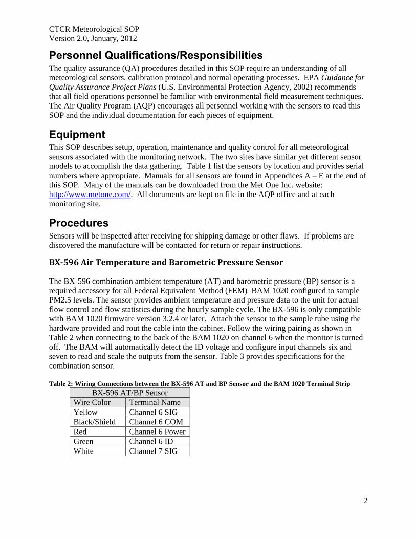
CTCR Meteorological SOP
Version 20 January 2012
2
Personnel QualificationsResponsibilities The quality assurance (QA) procedures detailed in this SOP require an understanding of all
meteorological sensors calibration protocol and normal operating processes EPA Guidance for
Quality Assurance Project Plans (US Environmental Protection Agency 2002) recommends
that all field operations personnel be familiar with environmental field measurement techniques
The Air Quality Program (AQP) encourages all personnel working with the sensors to read this
SOP and the individual documentation for each pieces of equipment
Equipment This SOP describes setup operation maintenance and quality control for all meteorological
sensors associated with the monitoring network The two sites have similar yet different sensor
models to accomplish the data gathering Table 1 list the sensors by location and provides serial
numbers where appropriate Manuals for all sensors are found in Appendices A ndash E at the end of
this SOP Many of the manuals can be downloaded from the Met One Inc website
httpwwwmetonecom All documents are kept on file in the AQP office and at each
monitoring site
Procedures Sensors will be inspected after receiving for shipping damage or other flaws If problems are
discovered the manufacture will be contacted for return or repair instructions
BX-596 Air Temperature and Barometric Pressure Sensor The BX-596 combination ambient temperature (AT) and barometric pressure (BP) sensor is a
required accessory for all Federal Equivalent Method (FEM) BAM 1020 configured to sample
PM25 levels The sensor provides ambient temperature and pressure data to the unit for actual
flow control and flow statistics during the hourly sample cycle The BX-596 is only compatible
with BAM 1020 firmware version 324 or later Attach the sensor to the sample tube using the
hardware provided and rout the cable into the cabinet Follow the wiring pairing as shown in
Table 2 when connecting to the back of the BAM 1020 on channel 6 when the monitor is turned
off The BAM will automatically detect the ID voltage and configure input channels six and
seven to read and scale the outputs from the sensor Table 3 provides specifications for the
combination sensor
Table 2 Wiring Connections between the BX-596 AT and BP Sensor and the BAM 1020 Terminal Strip
BX-596 ATBP Sensor
Wire Color Terminal Name
Yellow Channel 6 SIG
BlackShield Channel 6 COM
Red Channel 6 Power
Green Channel 6 ID
White Channel 7 SIG
CTCR Meteorological SOP
Version 20 January 2012
3
Table 3 BX-596 AT and BP Sensor Specifications
BX-596 Barometric Pressure Ambient Temperature
Voltage Output 0 to 25 volts 0 to 25 volts
Range 525 to 825 mmHg -40 to +55 degrees C
Accuracy plusmn 025 mmHg at 25˚ C plusmn 15˚ C above -30˚
ID Voltage 410 volts DC plusmn 002
After installing the sensor a flow calibration is performed following the instructions in the Air
Quality Monitoring Network Standard Operating Procedures for BAM 1020 PM 25 Monitors
The AT and BP can be adjusted in the STD column based on the reference standard
measurements The Default hot key can be pressed to reset the user calibration from the selected
parameter and replace it with a factory setting if values appear to deviate from expected
The BX-596 temperature output may also be checked in an ice bath The ice bath test is usually
never done except in some cold weather environments First calibrate the sensor at ambient
temperature and then use the following steps
1 Remove the stop screw from the bottom of the mounting bracket so that the electronics
module is free to rotate Rotate the module counter-clockwise until it disengages from the
keyhole slots and comes free from the radiation shield
2 The sensor comes with an 18 inch long ice bath extension harness This may be used to allow
the temperature bead to reach the ice bath if necessary Carefully unplug the black
temperature bead assembly from the top of the electronics module and install the harness
between the bead and the module
3 Insert the temperature bead into the ice water bath along with your reference sensor Avoid
immersing the bead assembly past the connector
4 Allow the bead to equilibrate then compare the AT reading in the TESTgt FLOW screen to
your reference sensor The tolerance for the regular BX-596 standard range sensor is plusmn 25 C
in temperatures below -30C
5 Remove the ice bath harness and reassemble the sensor
During operation of the BAM-1020 the output from the BX-596 can be viewed from the main
flow statistics screen or the OPERATE screens
Simple maintenance practices will keep the BX-596 operational which include
1 Make sure the four holes in the cover plate are clear by removing the bottom cover for
inspection
2 Clean the radiation shield assembly once each year
3 The black temperature bead assembly may be replaced if the bead becomes damaged The
assembly simply plugs into the top of the electronics module The sensor will need to be
recalibrated any time the temperature bead is replaced
4 The circuit board can only be serviced by the manufacture
BX-592 Temperature Probe and Shield This sensor provides temperature measurement of the outside air used to determine the
correction value as part of the volumetric flow calculation The sensor is designed to be
connected directly to one of the analog input channels of the BAM1020 The sensor comes with
CTCR Meteorological SOP
Version 20 January 2012
4
30 feet of cable and mounting hardware The sensor is mounted on the sample tube below the
PM10 and Sharp Cut Cyclone (SCC) air intakes The cable entry into the enclosure can be by a
weather tight hole in the top or side
Connect the cable onto the channel 6 location on the back of the BAM 1020 following the
pairing in Table 2 Table 3 provides specifications for the temperature sensor
Table 4 Wiring Connections between the BX-592 AT Sensor and the BAM 1020 Terminal Strip
BX-592 AT Sensor
Wire Color Terminal Name
Yellow or White Channel 6 SIG
BlackShield Channel 6 COM
Red Channel 6 Power
Green Channel 6 ID
The sensor shield provides protection for the temperature probe from direct solar radiation The
shape allows for the wind to naturally aspirate the shield to reduce the total effect of solar
radiation on the temperature measurement
Table 5 BX-952 Temperature Sensor and Shield Specifications
Temperature Probe Type
Thermistor Bead multi-element
Temperature Accuracy plusmn 002˚ degrees C
Temperature Range -30˚ C to + 50˚ C
Sensor Output
0 to 1 VDC for temperature range
Time Constant
10 Seconds in still air
Maintenance and calibration of the BX-592 consists of simple procedures recommended by Met
One Inc Maintenance includes cleaning the radiation shield once each year to prevent buildup
of material that would alter or decrease the reflectivity Temperatures are checked andor
adjusted during the flow verification process of the BAM 1020 as outlined in the monitoring
network SOP The temperature probe is not adjustable in the field and should only be repaired
by the manufacturer
Model 505 Wind Sensor The 505 Wind Sensors are a solid-state ultrasonic instrument capable of measuring wind speed
and wind direction in the U and V axes Sonic pulses are generated at the transducers and are
received by opposing transducers Mathematics derived for these sonic pulses provide a wind
velocity measurement in each of the corresponding axes
CTCR Meteorological SOP
Version 20 January 2012
5
The 505 uses a microprocessor-based digital electronic measurement system to control the
sample rate and compute the wind speed and wind direction The sensor is factory calibrated and
requires no field calibration In the field the operation of the sensor can be quickly checked
using a combination of simple tests A zero chamber or bag is used to verify the zero reference
by covering the entire sensor or individual outputs are checked by blocking various
combinations of sensors
The sensor is designed for installation in a Model 3188 mounting and alignment fixture (Figure
1) This provides a mount for use on a horizontal frac34 inch IPS pipe boom The 3188 Sensor
Mounting Fixture includes a keyed bushing which will be adjusted for alignment to North
orientation enabling the sensor to be removed and replaced without realignment Three captive
machine screws are used to secure the sensor to the keyed bushing Review page 22 of the
operation manual (Appendix C) for a diagram of a top of tower installation
Orientation of the sensor to true north can be accomplished by following the instruction on page
8 of the operation manual and should be necessary only on setup To prevent birds from
perching on the sensors stainless steel wire deterrents are installed prior to securing to the
alignment fixture Safety precautions should be followed during this operation because the
deterrents are very sharp
The External Heater provides de-icing for the sensor arms and prevents the accumulation of ice
which might block the sonic elements The heater consists of a laminated material that is
wrapped around the four sensor arms and sonic sensor element housings Heater power is
supplied from a Met One Instruments power unit in a weatherproof box The heater is activated
at 38 degrees F and will keep the arms ice-free at temperatures down to below -20 degrees F
The connection information can be found in Appendix C of this manual
The temperature controller electronics box should be mounted no more than 5 feet from the
sensor using the U-bolts and cable supplied with the heater controller A two conductor cable
spans the distance from the heater controller to the heater power supply The power supply
fastened to the tower with the U-bolts provided and then plugs into a three prong 120 volt AC
receptacle
Follow the instructions on page 12 of the operations manual for details on connecting the data
cable to the data logger Several options are available depending on which connection is needed
The data cable from the sensor to the data logger should be secured to the boom and tower with
cable ties The two wind sensors differ in voltage output 0 to 25 volts at Nespelem and 0 to 10
volt at Inchelium This difference is important when configuring the data loggers at each site
Operation of the 505 is essentially automatic no specific sensor calibration is required The
sensor has been calibrated in a wind tunnel at the factory prior to shipment The sealed sensor
cannot be adjusted in the field and there are no replaceable parts To ensure that the recorder is
scaled properly the manufacture recommends that zero and span tests are performed after the
sensor is connected and operational
CTCR Meteorological SOP
Version 20 January 2012
6
Figure 1 Model 505 Wind Sensor Components
CTCR Meteorological SOP
Version 20 January 2012
7
A zero test requires the prevention of air movement across the sensor by covering the array A
plastic bag can be placed over the array using care not to contact the transducers or block the
sonic paths between transducers The bag should be spaced at least 2 above the transducers to
avoid sonic reflections which may affect readings The bag can be tied at the bottom with a tie
wrap or tape to prevent air movement from below the wind can deflect the bag causing air
movement inside With no air movement across the array the sensor should indicate 00 to 01
ms wind speed The wind direction output will wander to any value between 0 and 360 degrees
The sensor is designed to produce known default outputs if an object blocks the sonic signal path
between the transducers This feature is useful for verifying sensor operation and recorder
scaling For testing purposes the sonic path can be blocked by placing a finger (or any solid
object) on the face of one or more transducers
The outputs after blocking the transducers are shown in Table 6 below
Table 6 Span Test Outputs for Blocked Transducers
Wind Speed
Blocked Axis Serial Output Analog Output 0-10 V 0-25 V
North-South 100 ms 50 ms 100 V 250 V
East-West 100 ms 50 ms 100 V 250 V
Both 100 ms 50 ms 100 V 250 V
Wind Direction
Blocked Axis Serial Output Analog Output 0-10 V 0-25 V
North-South 10 degrees 10 degrees 003 V 007 V
East-West 160 degrees 160 degrees 044 V 111 V
Both 170 degrees 170 degrees 047 V 118 V
The testing of the transducers can easily be accomplished when the tower is tipped down for the
yearly inspection Table 7 lists the specifications for the wind sensor
Table 7 Model 505 Wind Sensor Specifications
Wind Speed Specifications
Range 0 to 50 msec
Accuracy plusmn 02 msec le 113 msec or plusmn 2 ge113 msec
Resolution 01 msec
Wind Direction
Range 0 to 360deg
Accuracy plusmn3deg
Resolution 1˚
CTCR Meteorological SOP
Version 20 January 2012
8
Operation
Sample Rate 5 per second
Data Output Rate 1 per second
Sonic frequency 200 KHz
Output Signals
Wind speed voltage 0-50 VDC
Wind direction voltage 0-50 VDC
RS-232 1200 to 192K Baud
Power requirement
Sensor 9-18 VDC 10 mA 12 VDC Average power
External Heater Option 15 VDC 50 Watts
Environmental
Maximum Measurement range 0 to 65 mls
Operating Temperature -40degC to +55degC no ice
Extended Temperature Range -50degC to +55degC with external heater
Physical
Weight 55 Ibs
Dimensions 1929in high 938in diameter
Model 083D Relative Humidity Temperature Sensor
The 083D-1-35 Sensor is an extremely accurate and sensitive relative humidity and temperature
sensor Response is linear with small hysteresis and negligible temperature dependence The
sensors are installed in a radiation shield before shipping The 73B radiation shield (Figure 2)
mounts on the opposite end of the boom from the 505 wind sensor on top the tower The
radiation Shields and cables have Mil Spec screw-on or twist-on cable connectors that are pre-
fitted by Met One The cable should be secured to the boom and tower with cable ties
The Relative HumidityTemperature Sensor has been calibrated at the factory and will not
change unless it is damaged Blow on the sensor for a quick check for operation the RH will
rise To check for reasonableness of operation compare the measurement with a local weather
service facility The reading will not be exactly the same but should be similar Compare the
temperature measurement to the delta Cal standard reading when conducting flow verifications
The sensor may need cleaning due to the accumulation of dust or other substances that will affect
measurements Turn off power to the sensor before attempting to clean and keep off until dry
Cleaning with distilled water will be adequate in most instances If extremely dirty or covered
with substance water will not remove isopropanol can be used Follow the instruction in the
operations manual to prevent damage to the sensor when cleaning with liquids
CTCR Meteorological SOP
Version 20 January 2012
9
Figure 2 Model 073B Radiation Shield
Table 8 Model 083D RH and Temp Sensor Specifications
Sensing Element Thin-film Capacitor
RH Range 0 - 100
Temp Range -50deg to +50degC
Response Time 15 seconds at 20degC
RH Accuracy plusmn2 RH between 10 and 100 RH
Temp Accuracy 01degC
Hysteresis For 0 to 100 to 0 excursion le 1
Temperature Coefficient plusmn004 per 1degC
Output 0 - 1 V full scale
Input Power 12V DC
Barometric Sensor 090D
The 090D (2632-1) uses an active solid-state device to sense barometric pressure with a range of
26 to 32 inches of mercury and a voltage output of 0 ndash 1 volt The sensor attaches to the tower or
other convenient location with a ldquoJrdquo bolt Orient the J box with the pressure inlet port facing
down Install the cable through the water tight fitting and connect as shown in Figure 2
CTCR Meteorological SOP
Version 20 January 2012
10
Figure 3 Installing the Barometric Sensor 090D Wiring
The sensor has been calibrated at the factory and will not change unless damaged No field
modification or calibrations can occur To check for proper operation compare to a local
weather station to see if the readings are reasonable The measurement will not be exactly the
same due to differences in elevation and measurement parameter absolute or normalized to sea
level This sensor measures absolute inches of mercury BP can also be checked when
conducting regular flow verifications or calibrations on the BAM 1020 The deltaCal standard
measures BP as millimeter (mm) or millibars (mb) and can be converted to inches mercury by
multiplying mm X 03937 and mb X 00295
Maintenance consists of inspecting the pressure inlet port for blockages and removing
obstructions if found If service or recalibration becomes necessary then send the sensor to the
manufacture
Rain Gauge 375 001 Inches This sensor measures precipitation on a continuous basis and is low-maintenance The tipping
bucket collects 001 inches of precipitation then tips and drains This triggers a switch closure
pulse that is counted The tipping bucket and rain gauge are heated to prevent accumulation of
snow and ice The sensor has been calibrated at the manufacture and should not require
adjustments after installation Mount the sensor level on a platform using the built in level and
three adjusting legs Follow the instruction in the operations manual (Appendix F) for complete
installation instructions A debris screen should be removed during the winter when snow will
accumulate
After installation manually actuate the tip bucket mechanism three times and confirm the tips
have registered on the data logger Inspect and clean the tipping buckets periodically and
physically tip to verify recording on the data logger If the sensor has been damaged or appears
to need calibration follow the instruction in the operations manual
Table 9 Model 375C Rainfall Sensor Specifications
Orifice 8 Inch Diameter
Calibration 01 Inches Rain per Switch Closure
Accuracy plusmn 1 at 1 to 3 inches per hour at 70 Fdeg
Switch Type Magnet and Reed
Mounting 3 Pad for 14 inch bolts
Dimensions 8 Inch Diameter
CTCR Meteorological SOP
Version 20 January 2012
11
Power Requirement 110 VAC
Weight 75 Pounds
Quality Control and Quality Assurance Quality Control (QC) and Quality Assurance measure are minimal due to the reliability and low
maintenance of the meteorological sensors employed The following table list all standards
used maintenance needed and actions If sensors exhibit characteristics outside of these
parameters the manufacturer will be contacted for instructions Records related to Meteorological
sensors will be tracked on the site log and summaries semiannually
Table 10 Meteorological Sensor Quality Control and Assurance Measures
Sensor Criteria Action
BX-596 ATBP Sensor
BP varies more than plusmn10 mm Hg from deltaCal Standard BAM 1020 Calibration Following SOP
Temperature varies more than plusmn2degC from deltaCal Standard BAM 1020 Calibration Following SOP
Sensor shield andor probe damaged Contact Met One for instructions
BX-592 Outside Temperature Sensor Volumetric Flow
Temperature varies more than plusmn2degC from deltaCal Standard BAM 1020 Calibration Following SOP
Temperature shield andor probe damaged Contact Met One for instructions
Model 505 Wind Sensor
Yearly zero test reading 00 to 01 ms wind speed
Contact Met One for instructions if greater than these readings
Yearly span test
Contact Met One for instructions if readings do not match those shown in Table 6
Heater not functioning Contact Met One for instructions
Relative HumidityTemperature
Sensor 083D
Yearly check for reasonableness Compare with local weather station
Yearly check for operation Blow on sensor and confirm RH rise
Barometric Sensor 090D Yearly inspection
Clean pressure inlet port for blockages when needed
Compare to deltaCal Standard Contact Met One for instructions if values do not compare reasonably
Rain Gauge 375 001 Inches
Yearly check for operation Manually tip bucket and confirm reading
Yearly check for level Use adjustment legs to level
Damage or bucket set screws loose
Follow instructions in operation manual for calibration
CTCR Meteorological SOP
Version 20 January 2012
12
Reference EPA Requirements for Quality Assurance Project Plans EPA QAR-5 Office of Environmental
Information Washington DC EPA240B-01003 March 2001
Guidance for Quality Assurance Project Plans EPA QAG5 Office of Environmental
Information Washington DC EPA240R-02009 December 2002
Guidance for Preparing Standard Operating Procedures (SOPs) EPA QAG-6 Office of
Environmental Information Washington DC EPA6000B-07001 April 2007
Met One Instruments Inc (2008) BAM 1020 particulate monitor operation manual Prepared by
Met One Instruments Inc Grants Pass OR BAM-1020-9800 Rev G
Standard Operating Procedure for the Continuous Measurement of Particulate Matter Monitoring
Sites Confederated Tribes of the Colville Reservation Air Quality Program August 2011
CTCR Meteorological SOP
Version 20 January 2012
13
Appendices
BX-596 ATBP SENSOR MANUAL
Met One Instruments Inc 1600 Washington Blvd Grants Pass Oregon 97526 Telephone 541-471-7111 Facsimile 541-541-7116
BX-S9G Sensor Manual - copy Copyright 2007 Met One Instruments Inc All Rights Reserved worldwide No part of this publication may be reproduced transmitted transcribed stored in a retrieval system or translated into any other language in any form without the express written permission of Met One Instruments Inc
Appendix A BX-596 ATBP Sensor Operation Manual
About this Manual
The BX-596 is an optional combination ambient temperature and barometric pressure sensor for use with the BAM-1020 particulate monitor The BX-596 sensor is a required accessory for all BAM-1020 configured to sample PM25 levels effective March 2007 The sensor provides ambient temperature and pressure data to the unit for actual (volumetric) flow control and flow statistics during the hourly sample cycle The BX-596 is only compatible with BAM-1020 firmware version 324 or later This manual describes the installation and operation of the BXshy596 sensor Refer to the BAM-1020 operation manual as needed
The BX-596-1 is an extended range version for extreme cold or high altitude environments
BX-59G TemperaturePressure Sensor Installed on a BAM-1020 Inlet Tube
Specifications
I
I I
I
I
I I
BX-59G Barometric Pressure Ambient Temperature Voltage Output o to 25 volts o to 25 volts
Range 525 to 825 mmHg -40 to +55 deg C Accuracy plusmn025 mmHg 25 C plusmn 15C above -30
10 Voltage 350 volts DC plusmn 02
BX-59G-1 Barometric Pressure Ambient Temperature i
Voltage Output o to 25 volts o to 25 volts Range 400 to 825 mmHg -50 to +50 deg C
Accuracy plusmn15 mmHg plusmn 15C full scale 10 Voltage 410 volts DC plusmn 02
BX-596-98DD Manua RevBdoc Page 1 of 4
Appendix A BX-596 ATBP Sensor Operation Manual
Installation and Setup
Ensure that the BAM-1020 is sited and installed properly per the instructions in the operation manual
During the installation process you will need to provide an access point for the BX-596 sensor cable to enter the shelter where the BAM-1020 is installed In some cases it is easiest to simply drill a 38 hole through the roof of the shelter about six inches away from the inlet tube then feed the cable through the hole and caulk around it to prevent leaks
There may be a better place to feed the cable into the shelter in some applications The BXshy902903 environmental shelters supplied by Met One have pre-formed access holes in the side to allow the sensor cable to be routed to the BAM-1020 Decide the best way to route the cable into the shelter The BX-596 comes with a standard 25-foot sensor cable Longer cables may be ordered if required
Remove the PM 10 head and PM25 cyclone from the top of the BAM inlet tube Attach the BXshy596 to the inlet tube (about 8 to 18 inches from the top) with the supplied U-bolt hardware Make sure that the sensor is level and tighten the U-bolt securely
Make sure the BAM-1020 is turned off then attach the sensor cable to the connector on the bottom of the BX-596 Route the loose end of the cable into the shelter and to the back of the BAM-1020 Coil up any excess length of cable Attach the cable to the back of the BAM as shown in the following table
I
BX596 ATBP Sensor Connections Wire Color Function BAM Terminal
Yellow A T Signal Output Channel 6 SIG BlackShield Ground Channel 6 COM Red +12 VDC Channel 6 POWER Green Auto 10 Signal 350V Channel 6 10 White BP Signal Output Channel 7 SIG
Reinstall the PM10 head and PM25 cyclone and seal around the cable hole with silicone if required
Operation
When the BAM-1020 is powered up with a BX-596 installed the unit will automatically sense the 10 voltage from the sensor and configure input channels six and seven to read and scale the outputs from the sensor Note The BX-596 sensor requires BAM-1020 firmware revision 320 or later The BX-596-1 extended range version requires BAM-1020 firmware revision 362 or later If the BAM firmware is not current enough then the BAM will not automatically identify and scale the sensor
Appendix A BX-596 ATBP Sensor Operation Manual
Turn ON the BAM-1020 and perform a calibration of the BX-596 Note The calibration is performed in the TESTgt FLOW screen which will not be available unless the FLOW TYPE is set to ACTUAL in the SETUPgt CALIBRATE screen You will need a reference standard measurement for ambient temperature and barometric pressure
MULTIPOINT FLOW CALIBRATION TARGET BAM STD
ltCALgt ~~~ 238 238 C BP 760 760 mmHg
FLOW 1 150 150 150 LPM FLOW 2 183 183 183 LPM FLOW 3 167 167 167 LPM
CAL NEXT DEFAULT EXIT
1 Enter the TESTgt FLOW menu as shown above The nozzle will lower automatically when this screen is entered The BAM colurnn is what the BAM-1020 measures for each parameter and the STO column is where you will enter the correct values from your reference standard The ltCALgt symbol will appear next to the parameter selected for calibration
2 Measure the ambient temperature with your reference standard positioned near the BXshy596 sensor Enter the value from your reference standard into the STO field using the arrow keys Press the CAL hot key to correct the BAM reading The BAM and STO values should now be the same
3 Press the NEXT hot key to move the ltCALgt indicator to the BP field and repeat the same steps for barometric pressure
The DEFAULT hot key can be pressed to reset the user calibration from the selected parameter and replace it with a factory setting The DEFAULT calibration should be fairly close in most cases
The BX-596 sensor is almost always calibrated as part of a BAM-1020 flow calibration Always calibrate the AT and BP channels before calibrating the flow channels as the flow rate is affected by the temperature and pressure of the ambient air
The 8X-596 temperature output may also be checked in an ice bath The ice bath test is usually never done except in some cold weather environments First calibrate the sensor at ambient temperature then use the following steps
1 Remove the stop screw from the bottom of the mounting bracket so that the electronics module is free to rotate Rotate the module counter-clockwise until it disengages from the keyhole slots and comes free from the radiation shield
2 The sensor comes with an 18 inch long ice bath extension harness This may be used to allow the temperature bead to reach the ice bath if necessary Carefully unplug the black temperature bead assembly from the top of the electronics module and install the harness between the bead and the module
3 Insert the temperature bead into the ice water bath along with your reference sensor Avoid immersing the bead assembly past the connector
Appendix A BX-596 ATBP Sensor Operation Manual
4 Allow the bead to equilibrate then compare the AT reading in the TESTgt FLOW screen to your reference sensor The readings should match within plusmn15 degrees C for the BXshy596-1 extended range sensor Note The tolerance for the regular BX-596 standard range sensor is plusmn 25 C in temperatures below -30C
5 Remove the ice bath harness and reassemble the sensor
During operation of the BAM-1020 the output from the BX-596 can be viewed from the main flow statistics screen or the OPERATE screens See the BAM-1020 manual
JI -~J
1 1~
i gt
-- --- shyv_
Ice Bath Extension Harness
Maintenance The BX-596 is designed to be low-maintenance easy to access and resistant to harsh environments There are only a few maintenance items for the sensor besides routine calibration checks
bull Remove the bottom cover and make sure that the four holes in the cover plate are clear and have not been obstructed by insects or debris These holes allow the air pressure to equilibrate inside the sensor for the barometric pressure reading Clean the inside of the electronics enclosure every 12 months or as needed
bull Clean the radiation shield assembly at least once per year Dirty shields reflect away solar radiation less efficiently
bull The circuit board is not intended to be removed or serviced by the customer bull The black temperature bead assembly may be replaced if the bead becomes damaged
The assembly simply plugs into the top of the electronics module The sensor will need to be recalibrated any time the temperature bead is replaced
Technical Support
Should you still require support after consulting your printed documentation we encourage you to contact one of our expert Technical Service representatives during normal business hours of 700 am to 400 pm Pacific Standard Time Monday through Friday In addition technical information and service bulletins are often posted on our website Please contact us and obtain a Return Authorization (RA) number before sending any equipment back to the factory This allows us to track and schedule service work and expedite customer service
Phone (541)471-7111 Fax (541)471-7116 E-Mail servicemetonecom Web wwwmetonecom
Mail Technical Services Department Met One Instruments Inc 1600 NW Washington Blvd Grants Pass OR 97526
Appendix A BX-596 ATBP Sensor Operation Manual
warranty
Products manufactured by Met One Instruments Inc are warranted against defects in material and workmanship for a period of one (1) year from the date of shipment from the factory Offered products not manufactured by Met One Instruments Inc will be warranted to the extent and in the manner warranted by the manufacturer of that product
Any product found to be defective during the warranty period will at the option of Met One Instruments Inc be replaced or repaired In no case shall the liability of Met One Instruments Inc exceed the purchase price of the product
This warranty may not apply to products that have been subject to misuse negligence accident acts of nature or that have been altered or modified other than by Met One Instruments Inc Consumable items such as bearings and batteries are not covered under this warranty
Other than the warranty set forth herein there shall be no other warranties whether expressed implied or statutory including warranties of fitness or merchantability
Service
Ary product being returiled to Met One Instruments In for service repair or calibration must be assigned a return authorization (RA) number Please call (541) 471-7111 or (972) 412-4715 for an RA number and shipping instructions
Products manufactured by Met One Instruments Inc that are returned for service repair or calibration are warranted against defects in material and workmanship for ninety(90) days from date of shipment under the same conditions as stated above
999
Appendix A BX-596 ATBP Sensor Operation Manual
Temperature Probe amp Shield Model BX-592
Operation Manual BX-592-9800
1600 Washington Blvd Regional Sales amp Service Grants Pass Oregon 97526 3206 Main St Suite 106
Met One Instruments
Telephone 541-471-7111 Facsimile 541-541-7116
Rowlett Texas 75088 Telephone 972-412-4715 Facsimile 972-412-4716
Appendix B BX-592 Temperature Probe and Shield Operation Manual
Model BX-592 Temperature Probe amp Shield Operation and Installation Manual
INTRODUCTION The Model BX-592 is a temperature probe and shield for use with the BAM-1020 particulate analyzer The BX-592 is used specifically with the BX-962 Volumetric Flow Control System used on the BAM-1020 This sensor provides temperature measurement of the outside air used to determine the temperature correction value as part of the volumetric flow calculation The sensor is designed to be connected directly to one of the analog input channels of the BAMshy1020 The BX-592 is used when there is no other source of analog temperature output from an existing temperature system at the owners location The BX-592 includes 30 ft of cable as well as a mounting adapter that attaches to the inlet tube of the BAM-1020
INSTALLATION The BX-592 is installed outside near the intake of the BAM-1020 particulate analyzer Mounting hardware is provided for direct mounting on the BAM-1020 inlet tube as shown in figure 10 Attach the temperature probe and shield to the horizontal bar using the clips on the top of the temperature shield Push the shield up onto the horizontal bar and press the grey plastic clips together until you hear the snap of the retainer locking inplace
The fitting on the mounting arm should be mounted in a convenient place near the top of the inlet tube and out of the way of the supports used to hold the inlet tube in place Tighten the set screws on the mounting adapter to hold it in place on the inlet tube The horizontal bar can be moved as necessary to mount the shield in a suitable location near the inlet tube and the PM-10 or PM-25 inlet assembly
The cable from the sensor can then be run down through the roof of the shelter or building so that it can be connected to the sensor input channel terminal block on the back of the BAMshy1020 unit
Figure 1 Temperature Sensor Installation
BX-592 Manual 31JAN2001 2
Appendix B BX-592 Temperature Probe and Shield Operation Manual
The sensor input connection should be made at sensor location six This input channel is the one used for any external temperature analog input used for the temperature correction input required by the volumetric flow controller
The BX-592 Temperature Sensor and Shield provides a special ider1tification output signal that is used by the BAM-1020 to determine what type of sensor is connected to the BAM as well as determine what the range of the temperature sensor The electrical connections to the BAMshy1020 can be see in Figure 2 Be sure that the color code of the individual wires of the cable is followed so that the sensor is not connected incorrectly to the BAM-1020 There are four wires which are connected to the four terminals of the analog inputs at the back of the BAM unit
IO~=== laquo) SIG ~2P-~~~WHTd COM ~~BLK ----~_4z ~ PWR ~2P-REO ----- I I 0 ~d)J-GRN --shyUL=== ~
SIG ~
Figure 2 Sensor Connections to BAM
Figure 2 shows the connections from the BX-592 Temperature Sensor and Shield to the BAMshy1020 Particulate Analyzer Be sure that the temperture sensor cable is connected to channel 6 of the BAM-1020 otherwise the voltage output of the sensor will not be able to be used as the temperature reference of the volumetric flow controler
For correct operation of the volumetric flow control option BX-961 the BAM-1020 must be programmed for volumetric flow operation This is done from the SETUP then CALIBRATE and then FLOW TYPE screen The default is metered flow and will need to be set for volumetric flow for tt1ts option to work correctly See the BAM-1020 Manual section 414 for information on the Calibrate Screen and in section 63 for information on the field calibration of the flow system
SPECIFICATIONS The following are the specifications of the BX-592 Temperature Sensor and Shield These are subject to change as determined by Met One Instruments Inc The shield of the BX-592 provides protection of the temperature probe from errors that are caused by direct solar radiation The shape allows for the wind to naturally aspirate the shield to reduce the total effect of solar radiation on the temperature measurement
Temperature Probe Type Thermistor Bead multi-element
Temperature Accuracy
Temperature Range
Sensor Output o to 1 VDC for temperature range
Time Constant 10 Seconds in still air
BX-592 Manua13IJAN2001 3
Appendix B BX-592 Temperature Probe and Shield Operation Manual
The shield is mounted from the top of the shield using two snap clamps designed for a 1 diameter tube or a IPS Pipe The mounting adapter and a short boom are provided for attachment to the inlet tube of the BAM-1020
MAINTENANCE amp CALIBRATION The temperature probe and shield require no specific maintenance other than normal cleaning of dirt and dust to prevent the degredataion of the reflectiveness of the shield If there is any build up of materials inside the shield they should be cleaned out so that there is a free path for air flow around the temperature probe
On a regular basis the output of the temperature probe displayed on the screen of the BAMshy1020 should be checked against a reference thermometer to be sure that the BX-592 is providing accurate information for the calculation of volumetric flow There are no adjustments inside the temperature probe and any repairs should be handled by the factory
Before returning a faulty probe the factory should be contacted a RA (Return Authorization) should be obtained and the problem noted on the RA This will insure that the repairs are made quickly and returned for installation
TROUBLE SHOOTING
Symptom Identify Problem Solution Incorrect Temperature indicated on BAM Display
Verify that connections to the rear panel of the BAM are correct and to channel 6
Change wiring to follow diagram as indicated in figure 2 of this manual
From setup menu channel Change settings from parameters screen verify that MANUAL Mode to Auto ID channel 6 is set for Auto ID mode for probe to work and not in MANUAL Mode correctly Examine output of BX-592 to Using a volt meter measure verify that it has the correct voltage between the black and voltage output for the current white wires 0-1 volt is ambinet temperature equivalent to -30 to 50
degrees C Le 21degC =637 volts If this is not correct return probe for repair
Volumetric Flow Control is not operating
Go to the Setup then Calibrate screen menu and verify that the flow type is set to volumetric and not metered
Default setting is for metered it will be necessary to change setting to volumetric flow type
Examine rear of BAM-1020 and see if there is a flow adjusment knob on the back of the unit right above the vacuum line
If there is a knob here it is most likely that volumetric flow control is not installed on this unit Contact Met One Instruments for advice
Volumetric flow value does not match audit flow meter connected to BAM
From setup menu select flow and examine the current measured flow value of the BAM
Recalibrate the BAM flow meter using the proceedure in the manual section 63 Field Calibration of Flow System
Verify that the audit instrument being used has been calibrated for volumetric flow monitoring
Adjust flow audit device for correct measurement of volumetric flow
BX-592 Manual 3IJAN200 1 4
Appendix B BX-592 Temperature Probe and Shield Operation Manual
For any other specific problems with the BX-592 or the Volumetric Flow Option BX-961 contact the factory
Met One Instruments Inc 1600 NW Washington Blvd Grants Pass Oregon 97527
(541) 471-7111 Voice (541 ) 471-7116 FAX
service metonecom e-mail
Visit our web page at httpwwwmetonecom
BX-592 Manual 31JAN2001 5
Appendix B BX-592 Temperature Probe and Shield Operation Manual
MODEL 505 WIND SENSOR
OPERATION MANUAL Document No 505-9800
1600 Washington Blvd Grants Pass Oregon 97526
Met One Telephone 541-471-7111 Instruments Facsimile 541-541-7116
Regional Sales amp Service 3206 Main St Suite 106 Rowlett Texas 75088 Telephone 9724124715 Facsimile 972-412-4716
505-9800 Rev Edoc
Appendix C Model 505 Wind Sensor Operation Manual
Copyright Notice
505 Sonic Wind Sensor Manual
copy Copyright 2005 Met One Instruments Inc AI Rights Reserved Worldwide No part of this publication may be reproduced transmitted transcribed stored in a retrieval system or translated into any other language in any form by any means without the express written permission of Met One Instruments Inc
Technical Support Should you require support please consult your printed documentation to resolve your problem If you are still experiencing difficulty you may contact a Technical Service representative during normal business hours-730 am to 400 pm Pacific Standard Time Monday through Friday
Voice (541) 471-7111
Fax (541) 471-7116
E-Mail servicemetonecom
Mail Technical Services Department Met One Instruments Inc 1600 Washington Boulevard Grants Pass OR 97526
505-9800 Rev E Page 2
Appendix C Model 505 Wind Sensor Operation Manual
TABLE OF CONTENTS 1 GENEAAL INFORIIATION 5
2 INSTALLATION 5
21 LTNPACKlNG 5 22 PREPARATION 5 23 SENSOR SITING 6
Figure 2-1 Siting Wind Instroments 6 24 ORIENTATION WITH FIXTURE 7
Figure 2-2 Orientation Fixture 7 25 ORIENTATION WITHOUT FIXTURE (SEE FIGURE 2-3 AND 2-4) 8 26 EXTERNAL HEATER 8
Figure 2-3 505 Wind Sensor Components 9 Figure 2-4 Alignment aSensor to Troe North 10
27 INSTALLATION OF AVERY DETERRENTS 11 Figure 2-5 InstallatIOn ofAviary Delerrents I
28 CONNECTIONS TO RECORDING ELECfRONICS 12
Figure 2-7 Factory Standard Analog amp Rf-232 Output Connections (Cable 9574 wi Differential Amplifier
Figure 2-8 Factory Custom SDI-12 Output Connections 3
Figure 2-6 Amplifier (9573) attached to Cable (9574) and wiring in box 12
9573) 12
Figure 2-9 Factory Custom RS4221485 Output Connections 13 28 SIGNAL OUTPUTS ANALOG RS-232 ANDSDI-12 13 29 SIGNAL OUTPUTS - RS422 AND RS485 14
3 OPERATIONAL CHECK-OUT AND CALmRATION 14
31 GENERM 14 32 RECORDING ELECTRONICS 14 33 ZERO TEST 14 34 SPAN TEST 14
4 MAINTENANCE AND TROlTBLESHOOTING 15
41 GENERAL MAlNTENANCE SCHEDULE 15 42 TROlTBfJESHOOTING 15
5 TIIEORY OF OPEAATION 16
51 SPEED OF SOUND IN AlR 16 52 SPEED OF S()UND PRINCIPLE 16 53 CALCULATION OF THE WIND VELOCITy 16
6 SPECIFICATIONS 17
FIGURE 6- 505 Wind Sensor Outline Dimensions 18
APPENDIX A - WIND DIRECTION SENSOR ORIENTATION 19
APPENDIX B - WIND SENSOR MOUNTING OPTIONS 22
APPENDIX C - HEATER CONFIGURATION AND WIRING 23
APPENDIX D - RS2J2 COMMAND SET 25
GENERAL PROTOCOL 25
1 RS-2J2 DATA OUTPUT PROTOCOL 25
11 ERROR CODE 26
2 USER COMMAND SET _ 27
21 L8-VERBOSE CONTROL OF RS-232 PARAMETER LABELS 27
505-9800 Rev E Page 3
Appendix C Model 505 Wind Sensor Operation Manual
22 MS-MAxLMUM FULL SCALE WIND SPEED 27 23 SU-WINO SPEED UNITS 27 24 QU-QUlT 27 25 SB-SERIAL BAUD RATE 28 26 ST-SERIAL TRIGGER (RS-485 ONLy) 28 27 IT-SONIC TEMPERATURE 28 28 VN-VERSION NUMBER 28 29 VS-FULL SCALE ANALOG OUTPUT VOLTAGE FOR WINO SPEED Ai~O WINO DIRECTION 28
505-9800 Rev E Page 4
Appendix C Model 505 Wind Sensor Operation Manual
MODEL 505 WIND SENSOR OPERATION MANUAL
1 GENERAL INFORMATION
The Met One Instruments Model 505 Wind Sensor is a solid-state ultrasonic instrument capable of measuring wind speed and wind direction in the U and V axes Sonic pulses are generated at the transducers and are received by opposing transducers Mathematics derived for these sonic pulses provide a wind velocity measurement in each of the corresponding axes
The 505 uses a microprocessor-based digital electronic measurement system to control the sample rate and compute the wind speed and wind direction The sensor is factory calibrated and requires no field calibration In the field the operation of the sensor can be quickly checked using a combination of simple tests A zero chamber or bag is used to verify the zero reference by covering the entire sensor or individual outputs are checked by blocking various combinations of sensors
The 505 provides are variety of outputs to suit the connection requirements of the user Standard outputs are voltage and RS-232 SDI-12 and RS422485 outputs are configured at the factory
2 INSTALLATION
21 UNPACKING
Carefully remove the sensor from its shipping container and inspect it for damage Referring to the packing list check for shortages Any claims for damages should be filed promptly with the carrier
The sensor is a precision electromechanical transducer Always handle it with care exercising particular caution to ensure that the instrument is not subjected to side loading shock or other abuse After initial inspection keep the sensor in its shipping container for protection until actual installation
22 PREPARATION
For accurate measurements the sensor mount must be rigid with little or no movement from the wind The sensor is designed for installation in a Model 3188 mounting and alignment fixture This provides a mount for use on a horizontal IPS pipe (105- 00) boom Mounting information and diagrams can be found in Appendix B of this manual
The 3188 Sensor Mounting Fixture includes a keyed bushing which will be adjusted for alignment to North orientation This enables the sensor to be removed and replaced without requiring realignment Three captive machine screws are used to secure the sensor to the keyed bushing
If a temperature shield such as the Model 0738 is to be used in the configuration the Model 1539-4 Arm and 1552 Mount is recommended These parts provide the necessary mounting for a vertical mast of 0 IPS pipe (105 OD) This same configuration can also be used to mount other sensors as well as providing a way to mount the sensor on a vertical mast (See Appendix B for Mounting Details)
505-9800 Rev E Page 5
Appendix C Model 505 Wind Sensor Operation Manual
23 SENSOR SITING
The primary objective of instrument siting is to place the instrument in a location where it can make precise measurements that are representative of the general state of the atmosphere in that area Because most atmospheric properties change dramatically with height and surroundings certain somewhat arbitrary conventions must be observed so that measurements can be compared
lOT
Figure 2-1 Siting Wind Instruments
The standard exposure of wind instruments over level open terrain is 10 meters above the ground (WMO 1971) however optimum measurement height may vary according to data needs Open terrain is defined as an area where the horizontal distance between the wind sensor and any obstruction is at least ten (10) times the height of that obstruction An obstruction may be man-made (such as a building) or natural (such as a tree) (See Figure 2-1)
The wind instrument should be securely mounted on a mast that will not twist rotate or sway If it is necessary to mount the wind instrument on the roof of a building it should be mounted high enough to be out of the area in which the airflow is disturbed by the building This is usually 15 times the height of the building above the roof so that it is out of the wake of the obstruction This is not a good practice however and should only be resorted to when absolutely necessary
Wind instruments are best sited when they are used on towers The tower should be located in an open level area representative of the area under study Towers should be of the open grid type of construction such as is typical of most television and radio broadcast towers Enclosed towers stacks water storage tanks grain elevators cooling towers and similar structures should not be used
Wind instruments should be mounted above the top of the tower on booms projecting horizontally out from the tower If a boom is used it should support the sensor at a distance equal to minimum of twice or at best three times the maximum diameter or diagonal of the tower away from the nearest point on the tower On large towers with large verticals it may be best to place the sensor at least 5 tower leg diameters from the tower leg The boom should project into the direction which provides the least distortion for the most important wind direction For example a boom mounted to the east of the tower will provide least distortion for north or south winds
505-9800 Rev E PageS
Appendix C Model 505 Wind Sensor Operation Manual
Weather sensors are sensitive to direct or nearby lightning strikes A well-grounded metal rod or frame should be placed above the sensor installation In addition the shield on the signal cable leading to the translator must be connected to a good earth ground at the translator end and the cable route should not be vulnerable to lightning
24 ORIENTATION WITH FIXTURE
The Orientation Fixture Model 705 is used for very accurate positioning of the 505 sensor with respect to a benchmark or other object that can be visually obselVed If a compass is used to establish a benchmark the reading should be taken away from heavy metal objects which can affect the reading and should be corrected for declination of the magnetic north pole The benchmark is set to true north of the sensor site Information on determining true North can be found in Appendix A of this manual
The fixture contains a telescopic sight with crosshairs and includes a keyed base identical to that on the sensor The fixture is specifically designed for use with the 3188 Sensor Mounting Fixture The base of the fixture is keyed so that the object lens of the sight assumes the same position as the north side of the sensor
Before orienting the sensor ensure that it is vertical and adjust the cross arm as necessary Orientation of the sensor is then performed with the fixture installed on the cross arm in place of the sensor (The three screws in the base of the fixture must be tightened to ensure proper orientation in the cross arm) Loosening the three setscrews on the side of the sensor mount allows free rotation of the keyed bushing and orientation fixture The ring and fixture are then rotated to position the benchmark in the center of the sight crosshairs The sight can be tilted as necessary by loosening the slotted screw on the side of the fixture The set screws are then tightened the fixture removed and the sensor installed in its place The sensor is now oriented for zero (north) wind direction signal output when the wind is from north
OSIECTlENS
Figure 2 2 Orientation Fixture
The electrical connector on the bottom of the sensor should be properly mated to the cable connector and the three captive screws on the base of the sensor should be tightened
When using the orientation fixture assure that the two-piece mounting assembly is properly aligned The upper half of the assembly contains a horizontal peg which must seat in the vshynotch located in the lower half The knurled knob on the lower half is used to secure the two sections and should be tight
505-9800 Rev E Page 7
Appendix C Model 505 Wind Sensor Operation Manual
25 ORIENTATION WITHOUT FIXTURE (See FIGURE 2-3 and 2-4)
Establish a True North benchmark See Appendix A for aids to determine True North This should be a point directly north from the sensors mounted location This point should allow easy access so that a person may sight the sensor with a spotting telescope If a compass is used to establish a benchmark the reading should be taken away from heavy metal objects which can affect the reading and should be corrected for declination of the magnetic north pole The benchmark is set due north of the sensor site
One person is located at True North benchmark equipped with a spotting scope A second person is located at the sensor The sensor alignment may be established as follows
A Install the sensor into the alignment bushing and secure with the two setscrews under the 3188 Alignment Fixture Keep the three setscrews around the ring of the fixture loose so that the ring can be rotated into position
B Turn the sensor so that the sensor paints to the North benchmark Tighten the 3 setscrews and recheck align ment
C Connect the 9574-cable assembly to the sensor Secure cable to boom with cable ties or tape to prevent damage
D The sensor can be removed without requiring realignment at any time Simply remove the sensor The alignment bushing remains proper1y oriented in the fitting
26 EXTERNAL HEATER
The Optional External Heater provides de-icing for the sensor arms and prevents the accumulation of ice which might block the sonic sensor elements The heater consists of a laminated heater material that is custom designed and wrapped around the four sensor arms and sonic sensor element housings The heater controller requires 15 to 24 VACNDC at approximately 4-5 amps at startup There are jumper connections on the controller board for the selection of power source The controller is normally provided with the jumpers not installed This is for 24 volts AC operation of the heaters Heater power can be supplied from a power transformer or a Met One Instruments supplied power unit in a weatherproof box The proportional controlled heater uses maximum current at start-up and power requirement goes down as the sensorheater reaches stability The heater is activated at 38 degrees F and will keep the arms ice-free at temperatures down to below -20 degrees F The connection information can be found in Appendix C of this manual
The temperature controller electronics box should be mounted no more than 5 feet from the sensor using the cable supplied with the heater controller The power cable should be of minimum 16 AWG wire and cable length should be at a minimum to prevent power loss due to cable resistance at the 4-amp power requirement
505-9800 Rev E Page 8
Appendix C Model 505 Wind Sensor Operation Manual
MODEL 505 WINO SENSOR
NORTH SCREWPIN ____~~--
THIS SIDE TO FACE SOlTTH LABEL
NORTH SLOT HOLE~middot-c-lIIo-
SET SCREWS (3 EA FOR SECURING
KEYED BUSHING TO HORTH ORIENTATION
(7164- ALLEN KEY)
Figure 2-3 505 Wind Sensor Components
Page 9 505-9800 Rev E
Appendix C Model 505 Wind Sensor Operation Manual
SOUTHSIDE SENSOR TRANSDUCER SHOULD BE SEEN EaUALLY DIVIDED
BY NORTHSIDE (NEAR) ARM
Figure 2-4 Alignment of Sensor to True North
505-9800 Rev E Page 10
Appendix C Model 505 Wind Sensor Operation Manual
27 INSTALLATION OF AVERY DETERRENTS
To prevent birds from entering the pathway between the sensors a vertical stainless steel rod is located in the center of the sensor array_ To keep birds from perching on the sensors stainless steel wire aviary deterrent need to be installed on the sensor prior to installation in the fixture
NOTE The stainless steel wires used for the aviary deterrents are very sharp The wire is spring steel and there s the possibility that it could slip off during the installation Use care
when installing the aviary deterrent and be careful after installation
PROTECTIVE GLASSES SHOULD BE WORN DURING INSTALLATION
Installed A viarv Deterrents
area
AVIARY DETERRENTS bull PIIIih ends IowaIds eoch ltlttler lil qgten up
spring d1amccr bull Slide owr lranllducer 10 mounIing llIII bull ~6l as requRd 60 that avlary
delemK1N are pointed ~
MOUNTING AREA
Figure 2-5 Installation of Aviary Deterrents
WARNING If the aviary deterrents are not properly installed The sensor may experience signal degradation Install as shown DO NOT allow for the spring section of the aviary deterrent to contact the transducer portion of the sensor array_
505-9800 Rev E Page 11
Appendix C Model 505 Wind Sensor Operation Manual
28 CONNECTIONS TO RECORDING ELECTRONICS
Route the cable to the data-recording device Secure the cable with cable ties or tape The 9574shycable assembly contains 7 wires and a shield Typical wiring hookup is shown in the figures below Actual wiring will depend upon the version of the sensor To determine which of the three connections drawings apply examine the cable part number at both ends of the cable
Cable type 9574 includes the 9573 Differential Amptifier it is located at the end of the cable opposite the sensor connector The amplifier provides high immunity to any noise that might be picked up the sensor cables It is recommended that this cable with amplifier be used whenever connected to a single ended input recorder If necessary to remove the differential amplifier a wiring diagram has been included in the top of the small amplifier enclosure A small screwdriver is provided for use on the small terminal screws on the PC Board of the 9573 Amplifier Be sure that the connection color codes are followed so that no wiring error occurs See below
Warning If you are connecting this 505 to an older 3155-cable assembly and are using the black wire as signal common disconnect it because it will short out the RS-232 transmitter No damage will occur to the circuit but the 505 current consumption will increase by 20 rnA
TO SONIC
~ n 0 SHLD (WTIBN) +12Y(Wiri) 0 0 NIC wo oOt-(RpoundD 0 0 GND(GRN) WD 0lIT~ (OAN) 0 0 ncD(8LK) W8 ~+(BLU) 0 0 RXC(IRN) NC 0 0 WSIN+(BW) RXD(8fCN) 0 0 NIC TXDl8LJC) 0 0 WDW+(RED) OND(GRN) 0 0 WDIN-(ORN) NIC Omiddot 0 +12V(WtfT) SHLD (WTIBN) 0 J1 r-
TO DATALOGGIR
Figure 2-6 Amplifier (9573) attached to Cable (9674) and wiring in box
Sensor Common
Power Common WHITE
RED
+12V Power
BROWN RXRS-232 BLACK TXRS-232
Wind Direction Voltage BLUE OR YELLOW Wind Speed Voltag~
Shield WHITEBROWN
Figure 2-7 Factory Standard Analog amp RS-232 Output Connections (Cable 9574 wI Differential Amplifier 9573)
505-9800 Rev E Page 12
Appendix C Model 505 Wind Sensor Operation Manual
o NG[ GREEN WHITE
BROWN
aLACK
REO
BLUE OR YEllOW
Sensor Common
Power Common
+12VPower
Not Used
Not Used
Not Used SOI-12 Output
Shield WHITEBROWN
Figure 2middot8 Factory Custom SDI~12 Output Connections
ORANGE
RED
Sensor Common GREEN Power Common WHITE +12V Power
BROWN RX f
BLACK RX shy
TX+ BLUE OR YELLOW TX-
Shield WHITEBROWN
Figure 2-9 Factory Custom RS4221485 Output Connections
28 SIGNAL OUTPUTS - AnalogJ RS-232 and 501-12
The standard configuration of the sensor provides for a voltage outputs for wind speed and direction as well as RS-232 Data The default output voltage is 10 volts full scale for 50 meterssecond and 360 degrees of direction Alternate full-scale values can be changed by using the RS-232 command set discussed in Appendix O The R8-232 output occurs every second in the format S sssS 0 ddd ltcrgtltIfgt where ssss is the wind speed value up to 9999 and the direction ddd up to a value of 360 RS-232 output is at 9600 baud 8 data bits 1 stop bit and no parity
As an option an output of 801-12 Data from the sensor is available In this configuration it is the only available output and is in the format +ssss+ddd ltcrgtltlfgt The same values for sssS and ddd as the RS-232 format are output The 801-12 handshake is per the 801-12 specifications and format In this configuration the RS-232 output or analog output is no longer available from the sensor
505-9800 Rev E Page 13
Appendix C Model 505 Wind Sensor Operation Manual
29 SIGNAL OUTPUTS - RS422 and RS485
In this configuration the sensor has no analog outputs (see diagram Factory Custom RS422RS485 Output Connections The correct sensor cable for this configuration is part number 3379
The default serial trigger (sensor address) is 1 After receiving 1 the sensor will return wind speed and wind direction in the same format as with RS232 (S sSSs D ddd ltcrgtltlfraquo
To use the RS232 Command Set defined in Appendix 0 the sensor must first be put into Terminal Mode by sending (three exclamation points) The serial trigger is not used in this case and there must be only one sensor connected on the serial buss The sensor will return when in Terminal Mode and will then accept RS232 commands The au (quit) command will take the sensor out of Terminal Mode and return it to normal operating mode
3 OPERATIONAL CHECK-OUT AND CALIBRATION
31 GENERAL
Operation of the 50S is essentially automatic and no specific sensor calibration is required for normal operation The sensor has been calibrated in a wind tunnel at the factory prior to shipment
32 RECORDING ELECTRONICS
The sensor may be connected to a variety of data recorders and translators Standard wind speed range is O-SO mls and wind direction range is 0-360 degrees Standard output voltage is 0-10V with 0-2SV and O-SOV as available options Refer to the calibration certificate supplied with the sensor to determine the actual output
To ensure that the recorder is scaled properly it is recommended that zero and span tests are performed after the sensor is connected and operational
33 ZERO TEST
A zero test requires no air movement across the sensor array so a means of covering the array is needed A plastic bag can be placed over the array using care not to contact the transducers or block the sonic paths between transducers The bag should be spaced at least 2 above the transducers to avoid sonic reflections which may affect readings The bag can be tied at the bottom with a tie wrap or tape to prevent air movement from below Keep in mind that wind can defrect the bag causing air movement inside
The preferred method is to use a box insulated with foam to prevent reflections and spaced so that the top is at Jeast 2 above the transducers Again the bottom should be sealed around the sensor to isolate the array from ambient air movement
With no air movement across the array the sensor should indicate 00 to 01 ms wind speed The wind direction output will wander to any value between 0 and 360 degrees
34 SPAN TEST
The sensor is designed to produce known default outputs if an object blocks the sonic signal path between the transducers This feature is useful for verifying sensor operation and recorder scaling For testing purposes the sonic path can be blocked by placing a finger (or any solid object) on the face of one or more transducers
505-9800 Rev E Page 14
Appendix C Model 505 Wind Sensor Operation Manual
NOTE The following table defines the sensor outputs with blocked paths
Wind Speed Blocked Axis Serial Output North-South 100 mls East-West 100 mls 80th 100 mls
Analog Out~ut 50 mls 50 mls 50 mls
D-10V 100V 100V 100V
0-2SV 250V 250V 2S0V
O-SOV 500V SOOV SOOV
Wind Direction Blocked Axis Serial Output Analog Output D-10V 0-25V D-50V North-South 10 Deg 10 Deg 003V 007V 014V East-West 160 Deg 160 Deg O44V 111V 222V Both 170 Deg 1700eg 047V 118V 236V
4 MAINTENANCE AND TROUBLESHOOTING
The 50S sensor is sealed and there are no replaceable parts contained therein The sensor does not require periodic calibration and there are no internal adjustments that can be made
41 GENERAL MAINTENANCE SCHEDULE
12-24 month intervals
The Model 505 Wind Sensor should be inspected periodically for physical damage to the sensor array assembly cable and cable connections Inspect all transducers to be sure they are securely fastened
Schedule based on average to adverse conditions
42 TROUBLESHOOTING ------ --shy--=-----------------==-----~~---- ----~-~-~~~~~~---~-----~ ----~~~~~~~--
~________~piom _~ __ ____ _____ ~~o~babl~9_C1l1~~_~___ ~__+_-_-A-ct-io-n-to-R-eL-pa_ir__---i
Wind Speed output goes to full Blocked pathway 1 - Check path and clear scale
Failed sensor 2 - If clear contact factory for Return Authorization to repair sensor
Wind Speed output high but not Common mode voltage 1 - Replace cable with part full scale number 9574 (with 9573
differential-to- single-ended converter)
supply 2 - Use 3379 cable and power sensor with isolated power separate from recorder power supply
inputs 3 - Use 3379 cable and connect sensor signals to differential on recorder
505-9800 Rev E Page 15
Appendix C Model 505 Wind Sensor Operation Manual
5 THEORY OF OPERATION
51 SPEED OF SOUND IN AIR
The speed of sound in still air can be measured accurately between two points a few centimeters apart by two ultrasonic transducers set at that distance The resulting speed of sound is a known function of the air temperature and composition
The speed of sound waves in an ideal gas may be written
where R is the universal gas constant (083134 mJmol K) T is the temperature in Kelvin M is the molecular weight (gramsmol) of the gas and L is the ratio of heat capacities Cp and Gy Cp
and Cyare the specific heats at constant pressure and constant volume of the gas respectively
52 SPEED OF SOUND PRINCIPLE
The transit time of a sound signal traveling from one end of a sound path to the other separated by distance d can be written as follows (Schotand 1955)
where V is the total velocity Vdand Vnare velocity components in the directions parallel and normal to the sound path and C is the velocity of sound in still air If two transit times t1 and t2 in opposite directions on the same path are directed Vd can be obtained independent from V and Vn as follows
It is this principle that is used to compute the velocity of the air in the path between two opposing transducers
53 CALCULATION OF THE WIND VELOCITY
In still air t1 and t2 are equal For a distance 15 cm at 20deg C the transit time is approximately 450 IJs If a 20 mls wind is in the direction of the sonic pulse the transit time t1 will be approximately 427 IJs If the wind is opposing the sonic pulse the transit time will be approximately 482 IJs If these two values are used in the previous equation the resultant velocity from equation will be 20 ms
505-9800 Rev E Page 16
Appendix C Model 505 Wind Sensor Operation Manual
6 SPECIFICATIONS
Sonic Wind Sensor Model 606
Wind Speed Range Accuracy Resolution
Wind Direction Range Accuracy Resolution
Operation Sample Rate Data Output Rate Sonic frequency
Output Signals Wind speed voltage Wind direction voltage RS-232
Optional Digita) Outputs
Power requirement Sensor
External Heater Option
Environmental Maximum Measurement range Operating Temperature Extended Temperature Range
Physical Weight Dimensions
Options Signal Cable Horizontal Mount amp Orientation Fixture External Heater with Control Box External Heater Power Source Programming Cable amp Power Supply
oto 50 msec plusmn 02 rnIsec 113 msec or plusmn 2 gt- 113 msec 01 msec
5 per second 1 per second 200 KHz
0- 50 VDC (Specified at time of purchase) 0- 50 VDC (Specified at time of purchase) 1200 to 192K Baud
501-12 RS-422 or RS-485 (Specified at time of purchase)
9-18 VDC 10 mA 12 VDC Average power requires 75 amp pulse for 2msec
15 VDC 50 Watts
oto 65 mls -40degC to +55degC no ice -SOdegC to +55degC with external heater
S5 Ibs (25 Kg) 1929in (490mm) high 938in (238mm) diameter
PN 9S74 - Specify length PN 3188 SO5H 50SPS (100 to 240 VAC SO60 HZ) 1SVDC 4 amps TBD
Heater Options must be specified at time of purchase middotSpecifications Subject to Change without prior Notice
50S-9800 Rev E Page 17
Appendix C Model 505 Wind Sensor Operation Manual
LLJ-oIIIo----IOODfA
--20001t
FIGURE 6-1 505 Wind Sensor Outline Dimensions
505-9800 Rev E Page 18
Appendix C Model 505 Wind Sensor Operation Manual
APPENDIX A - WIND DIRECTION SENSOR ORIENTATION
INTRODUCTION Determining True North or Magnetic Declination is very important to the proper setup and orientation of the wind direction portion of the sonic wind sensor The declination value is used to determine the difference between True North and magnetic North This value varies around the world depending upon your location The following procedure can be used to either point the sonic wind sensor to True North
ADJUSTMENT Orientation of the wind direction sensor is done after the location of True North has been determined True North is usually found by reading a magnetic compass and applying the correction for magnetic declination where magnetic declination is the number of degrees between True North and Magnetic North Magnetic declination for a specific site can be obtained from a USGS topographic map pilots maps local airport or through a computer service offered by the USGS called GEOMAG
The following map showing magnetic declination for the contiguous United States is shown in the figure 1 can be used for determination of declination Tilis will depend upon the accuracy requirement required Alternately use a more accurate method of detemlining declination from magnetic North
Subtract declination from 3600 Add declination to 0deg 20W
Figure 1 typical declination values in the USA
Declination angles east of True North are considered negative and are subtracted from 0 or (360) degrees to get True North as shown in figure 2 Declination angles west of True North are considered positive and are added to 0 degrees to get True North as shown in figure 3 For example the declination for Grants Pass Oregon is 17deg East True North is 3600 -17deg or 3430 as read on a compass
505-9800 Rev E Page 19
Appendix C Model 505 Wind Sensor Operation Manual
Alignment to North Orientation is most easily done with two people one to aim and adjust the sensor while the other observes the wind direction display (Once True North is located the South reference can be determined)
1 Establish a reference point on the horizon for True North Sighting down the instrument centerline aim the two arms of the NorthSouth pair at True North with the locking set screw pointed South
2 Align the sensor adapter or adapter mount Loosen the setscrews that secure the base of the sensor to the cross arm While viewing the positionrotation of the Nortl1South sensor arms slowly rotate the sensor base until the two arms point to True North that was determined by earlier measurement using compass
Other methods employ observations using the North Star or the sun and are discussed in the Quality Assurance Handbook for Air Pollution Measurement Systems Volume IV Meteorological Measurements
Determining Local Magnetic Declination Several resources for determining the magnetic declination of any site in the world can be found on the internet or can be accessed by modem using any common terminal program
GEOMAG is a resource that can be accessed by telephone or the Internet (Telnet) connection GEOMAG is accessed by calling 1-800-358-2663 with a computer and telephone modem and communications program such as HyperTerminal GEOMAG can also be accessed by the internet using the address telnetllneiscrusgsgov
GEOMAG prompts the caller for site latitude longitude and elevation which it uses to determine the magnetic declination and annual change The follOWing Menu and prompts are from GEOMAG Use the username QED
MAIN MENU NeecJe POInfS toType Q for Quick Epicenter Determinations (QED) Magnetic North
L for Earthquake Lists (EaUST) M for Geomagnetic Field Values (GEOMAG) X to log out
Enter program option M
Would you like information on how to run GEOMAG (YN) N
FIGURE 2 Declination Angles East ofOptions True North Are Subtracted from 0 to Get True North 1 = Field Values(D I HXZ F)
2 =Magnetic Pole Positions 3 Dipole Axis and Magnitude 4 Magnetic Center
Display values twice [N] press return Name of field model [USCON951 press return Date [Current date] press return Latitude 4225 N Longitude 12320 W Elevation 1000 Units (mkmft) ft
FIGURE 3 Declinatiof1 Angles West of True North Are Added to 0 to Get True North
505-9800 Rev E Page 20
Appendix C Model 505 Wind Sensor Operation Manual
Example of report generated by GEOMAG Model USCON95 Latitude 4225 N Date 211399 Longitude 123120 W Elevation 1000000 ft
D I H X Y Z F deg min deg min nT nT nT nT nT
17 175 65 73 22056 21059 6555 47560 52425 Annual change 0 -24 0 -17 -29 18 -156 -662 -613
The calculated dedi nation would be 17 degrees and 175 minutes for Grants Pass Oregon The declination in the example above is listed as 17 degrees and 175 minutes Expressed in degrees this would be 173 degrees As shown in Figure 1 the declination for Oregon is east so True North for this site is 360 - 173 or 3427 degrees The annual change is -24 minutes In this case a value 343 degrees would probably be sufficient for most measurement accuracy
An alternative method is to find a USGS map and examine the text at the bottom center of the map At this point either a written indication is given or a symbol similar to the one seen below will be found This would indicate a declination of 15 degrees West-showing MN (magnetic North) to True North (Star) Other sources such as the local airport can be helpful in determining the correct declination
1D23 25 MilS
UTM GR-O AND 1971 MAGNETIC NORTH OECLINATION AT CENTER OF SHEET
505-9800 Rev E Page 21
Appendix C Model 505 Wind Sensor Operation Manual
r=======~ -C_ARM-c-r--r-___-r
193 MOUNTING BOOM
APPENDIX B - WIND SENSOR MOUNTING OPTIONS
TYPICAL VERTICAL MOUNTING WITH 191-6 CROSS ARM
3168 AtlGINT FlXTmE
TOP OF TOWER
TYPICAL HORIZONTAL MOUNnNG
3188 AlIGN1NT FIXTLRE
-34 IfICH PS PIPE OR II~CH DlA flO(J1
505-9800 Rev E Page 22
Appendix C Model 505 Wind Sensor Operation Manual
APPENDIX C - HEATER CONFIGURATION AND WIRING
5VJ H HEAT R HH~ING lJc_ r1
5fl5 WllO SENSOR WITH HEA TER ARRAY
3379 SIGNAL CADLE
I ALIGNMENT OASE MClJEL 3100 TEt-PERATURE
CONTROLLER
reg
505PS POWER SUPPL Y lJNIT NORMAL POWER INPUT
Fm HEATER bull bullVCLTS AC OR
TO SEIfJC)R j
HEATER UNIT
~ ro 2rJ0 VAC POWER
505-9800 Rev E Page 23
Appendix C Model 505 Wind Sensor Operation Manual
00
01 o yco o o 0 OPTIONAL ~ 505 PS SONIC WIND SENSOR m HEATER POWER SUPPLY
MOUNTl NG ON VERTICAL r PE~ 2-114 DIAMETEr-deg
---1__(I I rlif 1~I
AC POWER CORD S LONG
1201240 VAC POWER AT 14 AMPS INPUT OUTPUT 15 VDC AT 4 AMPS
U w
CO (J)
~
WEATHERPROOF ENCL
~ SONIC SENSOR - 5FT LONG ~
CUT AS NECESSARY 25 FT LONG auPPUED
2 CONDUCTOR 16 AWG CABLE BETWEEN POWER SUPPLY amp CONTROL BOX
HEATER CONTROL UNIT PART 3254 FOR SONIC WIND SENSORS
(SUPPLIED WITH HEATED SENSOR)
U08oa T FOR MOUNllNG ON VERLPIPE 314 TO z14 DIAMETER
---3871 [E-23Jrl J i II
CI In I In
WEATHERPROOF INCshy
POW UNSOR CABUi TO J
FOR USE WITH SONIC WIND SENSORS SOSHAND 03SAoH
I
Appendix C Model 505 Wind Sensor Operation Manual
APPENDIX D - RS232 Command Set
General Protocol
The computer interface commands use a simple ASCII packet protocol Only one command is transferred per packet
To enter the command mode send the exclamation point () character until the unit returns If
The unit will remain in the command mode until the quit command (QU) is received or a power reset
Command packets are constructed with a two (2) character command and if required a data string
All commands must end with a carriage return (OxOD)
The unit will echo back the command string terminated with a carriage return and line feed (OxOA)
Data string requirements are described with each command
A command with no argument returns the current setting
The default R5-232 configuration is 96008 N 1
There are two command sets-User and Factory
1 RS232 Data Output Protocol
The typical RS-232 data output stream has the following format
S ssss D dddltcrgtltlfgt
Where ssss is the wind speed value and ddd is the wind direction value The range of the direction value is 0 to 359 degrees
The units of ssss are determined by the SU (Speed Units) settings
The data output rate is determined by the TS (Sample Period) settings
Parameter labels can be suppressed by the LB setting The output format follows
ssss dddltcrgtltlfgt
The sonic temperature reading can be added to the data output with the TT (Sonic Temperature) setting The output format follows
S sSSs D ddd T ttttltcrgtltlfgt
The units of ttlt are in degrees C
The sonic error code can be added to the data output with the EE (Sonic Error Code) setting The output form follows
s sSSs D ddd T ttU E eeeltcrgtltlfgt
505-9800 Rev E Page 25
Appendix C Model 505 Wind Sensor Operation Manual
11 Error Code There is a time-of-flight window establish to determine sensor failures If the receive signal arrives before the window it is considered early If is arrives after the window it is considered late There is an early and late error code for each sensor
The firing order is NWSE so the receive order is SENW The error code table follows
Early Late
N 1 2
S 4 8
W 16 32
E 64 128
The error code output is the sum of the sensor failures An error code does not mean the speed or direction values are invalid Here is an example
S 34 D 77 E 16ltcrgtltlfgt
The speed or direction values are invalid when an axis failure has occurred for three (3) consecutive sample periods
An axis failure is when each sensor of the sensor pair has a failure-early or late When this condition occurs the speed is set to an equivalent of 1000 meter-per-second The actual speed report is determined by the SU setting The direction is equal to the error code
For example if the north-south axis is block and SU is MPS the data output looks like this
S 1000 0 10 E 10ltcrgtltlfgt
If the east-west axis is block and SU is MPH the data output looks like this
S 2237 D 160 E 160ltcrgtltlfgt
If the north-south and east-west axis is block and SU is KPH the data output looks like this
S 3600 D 170 E 170ltcrgtltlfgt
505-9800 Rev E Page 26
Appendix C Model 505 Wind Sensor Operation Manual
- -- --
2 User Command Set
Note ltcrgt refers to a carriage return
21 LB-Verbose Control of RS-232 PARAMETER labels
Display or suppress parameter labels of Wind Speed (S) Wind Direction (D) Sonic Temperature (T) and Error Code (E) at RS-232 output
COMMAND RESULT LBltcrgt Report Present Setting LBOltcrgt Suppress parameter labels LB1ltcrgt Display parameter labels
22 MS-Maximum Full Scale Wind Speed
Set the units full-scale Wind Speed output for full-scale analog output Note that these numbers MUST correspond to units set in SU below
Example COMMAND RESULT MSltcrgt Report Present Setting
-----~~
MS50ltcrgt 50 Meters per second when SU = 0 ~----- --~ -~---
MS11185ltcrgt -~~
11185 MPH when SU = 1---__--shy-MS1800ltcrgt 180 KPH when SU = 2 MS9719ltcrgt 9719 KNOTS when SU = 4
- ------- ~---
23 SU-Wind Speed Units
Set units for Wind Speed
COMMAND ULT SUltcrgt Re ort Present Units selected ------------ --middot---------+--M--P-S=-------------~----ISUOltcrgt SU1ltcrgt MPH SU2ltcrgt KPH SU4ltcrgt Knots
These values are mutually exclusive
24 QU-Quit
Exit the command mode and save any changes
COMMAND QUltcrgt Note This command not supported by SDI-12
505-9800 Rev E Page 27
Appendix C Model 505 Wind Sensor Operation Manual
25 SB-Serial Baud Rate
Read or Set the units Baud rate Note This command is not supported by SOI-12
SB2ltcrgt Set 2400 BAUD S83ltcrgt Set 4800 BAUD SB4ltcrgt Set 9600 BAUD SB5ltcrgt Set 19200 BAUD
Baud rate changes take effect after turning off the power to the sensor and turning it back on again
26 ST -Serial Trigger (RS-485 Only)
Set the string used in RS-485 mode to serve as a trigger for the units send data command
COMMAND STxltcrgt Where x can be any set of one to six alphanumeric characters except three in a row
27 TT-Sonic Temperature
Enable or disable Sonic Temperature RS-232 output
COMMAND RESULT TTltcrgt Report Present Output Status TTOltcrgt Disable Sonic Temperature Output TT1ltcrgt Enable Sonic Temperature Output
28 VN-Version Number
Returns the Firmware version number
COMMAND VNltcrgt Example Report 3194-02 R26o
29 VS-Full Scale Analog Output Voltage for Wind Speed and Wind Direction
Set the full-scale analog output voltage for the full-scale wind speed and wind direction
COMMAND V5xxltcrgt Where xx is the full-scale analog output voltage at the full-scale wind speed and wind direction
The range ofxx is 00 to 50 volts at the full scale
505-9800 Rev E Page 28
Appendix C Model 505 Wind Sensor Operation Manual
Warranty
Products manufactured by Met One Instruments Inc are warranted against defects in material and workmanship for a period of one (1) year from the date of shipment from the factory Offered products not manufactured by Met One Instruments Inc will be warranted to the extent and in the manner warranted by the manufacturer of that product
Any product found to be defective during the warranty period will at the option of Met One Instruments Inc be replaced or repaired In no case shall the liability of Met One Instruments Inc exceed the purchase price of the product
This warranty may not apply to products that have been subject to misuse negligence accident acts of nature or that have been altered or modified other than by Met One Instruments Inc Consumable items such as bearings and batteries are not covered under this warranty
Other than the warranty set forth herein there shall be no other warranties whether expressed implied or statutory including warranties of fitness or merchantability
Service
Any product being returned to Met One Instruments ~n for service repair or calibration must be assigned a return authorization (RA) number Please call (541) 471-7111 or (972) 412-4715 for an RA number and shipping instructions
Products manufactured by Met One Instruments Inc that are returned for service repair or calibration are warranted against defects in material and workmanship for ninety(90) days from date of shipment under the same conditions as stated above
999
Appendix C Model 505 Wind Sensor Operation Manual
MODEL 083D RELATIVE HUMIDITYTEMPERATURE SENSOR
OPERATION MANUAL
1600 Washington Blvd Regional Sales amp Service Grants Pass Oregon 97526 3206 Main St Suite 106 Telephone 541-471-7111 Rowlett Texas 75088 Facsimile 541-471-7116 Telephone 972-412-4715
Met One Facsimile 972-412-4716
Instruments
Appendix D Model 083D Relative HumidityTemperature Sensor Operation Manual
0830 RELATIVE HUMIOITVrrEMPERATURE SENSOR OPERATION MANUAL
10 GENERAL INFORMATION
11 The 0830 Sensor is an extremely accurate and sensitive relative humidity sensor which responds to the full range of 0-100 humidity Response is linear with small hysteresis and negligible temperature dependence The sensor is designed to be housed in a radiation shield when used outdoors Certain models also contain a high-accuracy linearized air temperature sensor permitting simultaneous measurement of relative humidity and temperature
1 2 The 0830 Sensor model number describes the sensor options as follows
0830 - A - 8
X is the temperature option
o = no temperature sensor = -50 to +50degC temperature sensor
Other temperature options are available
Y is the radiation shield compatibility option
~ Radiation Shield Signal Cable
- 1 071 1873 -XX (XX = cable length in feet) - 6 076 2144-XX - 6 077 2408 -XX - 35 0738 2348-XX - 35 0758 2348-XX -35 5980 2348 -XX
13 The Sensor Cable is vinyl-jacketed and shielded Cable length is given in feet on each cable part number The cable part number depends on which radiation shield the sensor is mounted in The 077 Radiation Shield has a screw type terminal strip to accept wire leads from the 2408 cable All other Radiation Shields and cables have Mil Spec screw-on or twist-on cable connectors
The 0830-X-6 sensor mounts in either a 0768 Radiation Shield with a 2144-XX signal cable or a 077 Radiation Shield with a 2408-XX signal cable The 0830-X-35 mounts in a 0738 0758 or 5980 Radiation Shield with a 2348-XX signal cable
0830-9800 2199 Page 1
Appendix D Model 083D Relative HumidityTemperature Sensor Operation Manual
Table 11 Model 083D Relative Humidity Sensor Specifications
Sensing Element Thin-film capacitor
Range 0-100 RH
Temperature Range
Response Time 15 seconds at 20degC 90 of final RH value
Accuracy Better than plusmn2 RH between 1 O~o RH and 100 RH
Hysteresis For 0 to 100 to 0 excursion less than plusmn 1
Temperature Coefficient
Output o - 1 V full scale (standard)
Input Power 12V DC plusmn 2V 12 ma
Table 12 Model 083D-1 RHlTemp Sensor Specifications
Range -50 0 to +50degC (standard range)
Accuracy
Time Constant 10 sec
20 INSTALLATION
21 If sensor comes mounted in a radiation shield refer to radiation shield manual section for mounting details Sensors not furnished in a radiation shield should be mounted in a representative location having good air flow and shaded from sunlight or other heat radiation sources that would affect measurement of relative humidity or temperature
Page 2
Appendix D Model 083D Relative HumidityTemperature Sensor Operation Manual
fl I~STALL5E~R ItJ -511EU)1leJ2 Ate c ---=--=_ De~PA~ ~=IflE
SEtJ50R MRpound COJshyNECl1C+-1lgt )1 J CfY
lERMJNAL WIRE I BLK0FU~) 2 7 GRN 8 YEL 9 WIT
QfD(IF~)
MODEL 0]65
MODEL 0]35
REMOVE SCREW TO SEPARAtE OEN504 BEARI)lCr -OJ~I-JG FROM VANE JepoundH
SET~W5 (3eA)~RU ERG ~SG HOLD 5EtJ~R 1-1
O~ELD
MODEL 0f_l
TYPiCAL 0530 5EN50R N5TALLATI0~6 IN 5fANDARD RADJATJOM 5l-4lELD5
0830-9800 2J99 Page 3
Appendix D Model 083D Relative HumidityTemperature Sensor Operation Manual
30 OPERATIONAL CHECK-OUT AND CALIBRATION
31 Relative Humidity Measurement
32 Relative Humidity Sensor Check-out
1 To verify correct wiring and as a rough test of sensor operation blow on the sensor The relative humidity will rise to a higher level
2 The Relative Humidity Sensor has been calibrated at the factory and will not change unless it is damaged To check for proper operation of the sensor it is advised that the output signal be checked against a local weather service facility Exact correlation is not to be expected due to atmospheric and geographical variations
33 Temperature Sensor
1 Compare actual readings with precision mercury thermometer As an alternative measure sensor resistance with a Lo Current Digital Ohm Meter and compare readings of temperature vs resistance See Table 42
40 MAINTENANCE AND TROUBLE SHOOTING
41 General Maintenance Schedule
6 - 12 Month Intervals
A Inspect sensors for proper operation per Section 30
B Clean Relative Humidity sensor element per Section 42A
Schedule is based on adverse to average environments
42 083 Relative Humidity Sensor Maintenance and Calibration
Warning The sensor can be miscalibrated or permanently damaged through improper acts Do not attempt a repair or calibration if you are unsure of the procedure Do not touch the sensor element if you do not know the correct procedure
This instrument should operate for an extended period of time with a minimum of care or maintenance
If parts or maintenance assistance are required contact Met One Instruments Obtain shipping instructions before returning any unit
0830-9800 299 Page 4
Appendix D Model 083D Relative HumidityTemperature Sensor Operation Manual
43 Sensor Element Maintenance
Cleaning the Sensor Element Unscrew the filter Dust and other particles may be removed by gently blowing on the sensor chip DO NOT USE COMPRESSED AIR DO NOT USE DETERGENTS DO NOT APPLY POWER TO THE SENSOR WHEN CLEANING and do not reconnect power to the sensor until the element has dried
CAUTION NEVER TOUCH THE SENSOR CHIP WITH BARE HANDS
1 The life of the sensor is related to the environment in which it operates In a pure air and water vapor surrounding the sensor element will have an indefinite life The presence of chemical pollutants in the environment may corrode the materials of the sensor chip The polymer material is resistant to most chemical attacks but the metal electrodes are sensitive to corrosion effects particularly when a DC voltage is applied to the sensor The most harmful pollutant has been sulphur dioxide absorption in small soot particles When such particles fall on the thin metal electrode they may if water condensation is present form traces of sulphuric acid to corrode the surface of the sensor For these reasons a careful cleaning as described in the preceding paragraph is recommended whenever the sensor has been exposed to corrosive pollutants Also a periodic cleaning every two weeks with an atomizer of distilled water thoroughly washing the chip clean may remove harmful particles before they can damage the sensor Be sure that no power is applied when washing the chip and that power remains off until after the chip has dried
2 The safest way is always to use distilled water However if the dirt can not be washed out with the water you can use also isopropanol In that case the instructions are -rinse the sensor in isopropanol during 1 min (immersed move it every now and then) -rinse the sensor in water during 15min (can be left immersed in water) -let the sensor dry
3 Replacement of Sensor Element If the sensor element has been damaged it can be easily replaced Disconnect power to the probe Unscrew the filter Un-plug the old sensor element and plug a new one in its place The sensor chip is very delicate so observe the following precautions DO NOT TOUCH THE SENSOR ELEM ENT WITH BARE HANDS Handle the sensor element only gripping the nylon edge Do not bump the sensor element when reinstalling the protective grid
4 After replacement of the sensor element the humdity probe must be recalibrated
SPARE PARTS 820202 ELEMENT 560014 FILTER MEMBRANE 560015 FILTER BRONZE
44 Relative humidity Calibrator model 3226
0830-9800 299 PageS
Appendix D Model 083D Relative HumidityTemperature Sensor Operation Manual
It is essential that the functioning of an instrument is checked against a reference from time to time Humidity Calibrator Model 3226 is used to make calibration and spot checking of humidity probes and transmitters easy and reliable
The operating principle of the 3226 is based on the fact that a saturated salt solution generates a certain relative humidity in the air above it The reading of the humdity probe or transmitter can then be adjusted accordingly This is a generally accepted and reliable method for calibrating humidity instruments - many leading laboratories use this method Usually two or three different salt solutions are used which are chosen according to the application
The structure of the 3226 is designed to ensure fast and stable temperature equilibration No external power is required In addition to laboratory use it is also suitable for one-site checks Special transit covers make the 3226 particularly simple to transport These features together with the pre-measured salts with a long lifespan (even after taken into use) make the 3226 the ideal choice for the most demanding user
The calibrator is provided with certified salts A sample calibration is made from each batch in the Measurement Standards Laboratory (MSL) The uncertainities achieved using these salts at eg+20 C are given here
Liel salt 11RH (plusmn 13 RH) NaCI salt 75RH (plusmn15 RH)
3226 includes a thermometer which is used for measuring the temperature during the calibration and can also be used for checking temperature measurement accuracy of the transmitter The accuracy of the thermometer is plusmnO3degC Each thermometer has been calibrated
45 Humidity Probe Calibration using 3226
1 The calibration method described in this instruction manual is based on the constant water vapor pressure over saturated salt solutions and constant temperature Materials used for the calibration are Lithium Chloride (LiCI) and Sodium Chloride (NaC) The former creates a humidity of approximately 11 and the latter approximately 75 in 68degF (20degC) ambient temperature Both of these chemical agents are available from chemical suppliers To guarantee accurate calibration the salts must be of high purity
2 Preparations for Calibration
Refer to instructions with the calibration bottles for mixing the solutions
The calibration bottles can be used for up to one year without changing to fresh
0830-9800 2199 Page 6
Appendix D Model 083D Relative HumidityTemperature Sensor Operation Manual
The calibration bottles can be used for up to one year without changing to fresh chemicals The bottles should be stored in a place with constant temperature so as to have them ready for use with just a short preparation time Do not shake the bottle with salt solution before use Care should be taken to see that there are no droplets of salt solution inside the mouth piece of the bottle This might affect the accuracy of the calibration Do not get any salt solution on the sensor element directly
TABLE 41 Calibration Tables
LITHIUM CHLORIDE
Ambient Temperature degC 1 0 1 5 20 25 30 35 40
Calibration Value RH 11 3 11 3 11 3 11 3 113 113 11 2
SODIUM CHLORIDE
Ambient Temperature QC 1 0 1 5 20 25 30 35 40
Calibration Value RH 757 756 755 753 751 749 747
A CALIBRATION FOR LOW HUMIDITY (13 RH)
1 Unscrew the filter Do not bump the sensor element while removing the grid
2 Pull the rubber plug out of the lithium chloride (LiCI) bottle and push the sensor probe in its place in the corks sleeve The sleeve is fitted with a safety flange and prohibits the probe from falling through
3 Read the ambient room temperature
4 Note the humidity percentage from the lithium chloride calibration table which corresponds to the temperature in question
5 After 1 hour read the humidity value If the reading differs from the table value adjust R15 zero adjust
6 After use close the bottle tightly with the rubber plug
B CALIBRATION FOR HIGH HUMIDITY (76)
Repeat the calibration procedure as described above but now using the sodium chloride Adjust R18 (span adjustment) if necessary
C Repeat steps A and B until no further adjustments are required TABLE 42
0830-9800 2199 Page 7
Appendix D Model 083D Relative HumidityTemperature Sensor Operation Manual
Sensor Model 083-1-x
Tc Rt Te Rt Tc Rt degC kD degC KD DC kD - 5 0 158181 - 1 4 47173 1 9 21908 middot49 150561 - 1 3 45997 20 21423 - 4 8 143555 bull 1 2 44861 2 1 20949 - 4 7 137093 - 1 1 43761 22 20484 -46 131114 - 1 0 42696 23 20029 - 4 5 125564 - 9 41665 24 19583 -44 120400 - 8 40665 25 19147 - 43 115583 - 7 39696 26 18719 -42 111079 - 6 38755 27 18300 - 4 1 106858 - 5 37843 28 17899 -40 102895 - 4 36957 29 17147 - 39 99166 - 3 36097 30 17092 - 3 8 95651 - 2 35260 3 1 16705 - 3 7 92333 - 1 34447 32 16325 - 3 6 89196 0 33657 33 15952 - 3 5 86224 1 32888 34 15586 -34 83406 2 32139 35 15227 - 3 3 80729 3 31410 36 14875 - 3 2 78183 4 30700 37 14529 - 3 1 75760 5 30009 38 14190 - 3 0 73449 6 29335 39 13856 - 2 9 71245 7 28677 40 13528 -28 69138 8 28037 4 1 13206 - 2 7 67124 9 27411 42 12890 - 2 6 65195 1 0 26801 43 12579 -22 58242 1 1 26206 44 12274 - 2 1 56671 1 2 25624 45 11974 - 2 0 55160 1 3 25056 46 11678 - 1 9 53705 1 4 24501 47 11388 - 1 8 52303 1 5 23959 48 11102 - 1 7 50952 1 6 23429 49 10822 - 1 6 49648 1 7 22911 50 10545 - 1 5 48389 1 8 22404
Sensor Range = -50 to +50c C (-58 to + 122degF)
Conversion Formulas Tc (( ( Rt- 1 ) + ( 2 3 1 00 -1 ) ) -1 shy 136983) - 129163 Rt = ((((-129163Tc)+136983)-1) - 2 3100- 1) - 1
Where Tc= Temperature in degC Rt =Sensor Resistance in Ohms (Q)
0830-9800 2199 Page 8
Appendix D Model 083D Relative HumidityTemperature Sensor Operation Manual
---
9 ~
sect ~ ltD
ffVSI(N)
iO I IISOHPTHJl ~
C I REDRAWN PER EO 1131 DH
A B C D E F
lIlT
GRN
YEL ELK
REO
H2 VOLT POWER
COhUION
RH SIGNAL
TElaP COW WON TEWP SIGNAL
SHIELD
ITEiI PART NO I- shy -shy
1 500391
DESCRIPTION
CONNECrOR 6 PIN FEMALE
QTY
1
2 480508 CLAilP 1
3 600193 LUG SPADE 116 6
4 400014 CABLE 5 COND bull SHIELDED VR
5 960050 SUEV ING 14 SHRINK VR
6 9600n SLEEVING 16 SHRINK vR
7 I- shy
8
980510
960060
lIRE 22 AIG WHTBRN
SLEEVING 14 CLEAR SHRINK
6
VR
9
10
SENSOR END TRANSLATOR END 6~
F
E~A DUB
C
SOLDER CUP VI n
~ (D
IDENTIFY CABLE 18 FROM EACH END MET ONE INSTRUMENTSamp DASH NUMBER LENGTH IN FEET ASSY CABLE 083 RH
AND TEMPERATURE
-0
Appendix D Model 083D Relative HumidityTemperature Sensor Operation Manual
8
~ o ~
~
U
~ o
ipoundfISIa6
I~I ~I~ I ~~ ~ PROD iEL 521112 ~ B EO 11 ~ I ~1~2 DB
IDT +12 VOLT POWER
COIIIION BLU OR YEL SICNAL
au TEIIP COM RED TEMP SIG
SHIELD
SENSOR END TRANSLATOR END
-6middot---shy
4amp ~ 4amp4 ~
ITEM PART NO DESCRIPTION QTY
1 500351 CONNECTOR 8 PIN FEJLE 1
2 460gt00 CLAMP 1
3 800193 LUG SPDE e 8
4 400014 CDLE ~ COND bullbull SHIELDED vi
1e0050 SLEEVING 11 SBRINI Vi
8 960075 SLEEVING V8 SBRINI Vi
7 960510 liRE 22 nG fBTBRN e
8 j800M SLEEVING 1 CLER SHRINI VR
9
10 -
A
0 D
SOLDER C11P YIO
1 IDENTIFY CABLE 18 ROil EACH END ill DASH NUMBER bull UNGTH IN nn
WET ONE INSTRUWENTS
ASSY CABLE RELATIVE HUMIDITY AND TEWPERATURE
2348
Appendix D Model 083D Relative HumidityTemperature Sensor Operation Manual
o Q) w o ltb Q) o o
~ ~
1J ~ CD
~------------------------------------------------------------------------------------------------------------------------
AlB TEIiP OGO
DIFF TE P 062
DIFf TEMP 01S2
DEIPOINT OR ~ RELiTIVE HUMIDITY
OPTION
fFi lI~rP111)1 ~
D IREDRUN UD ADD paTS LIST DB
BLI BRH RED ORC
YEL CRH
BLU VIO CRY
flIT
SIGNAL CO MON
SIGNAL COON
SIGNAL COON
COMMON SIGNAL POUR OPTION SHIELD
K
ITpoundII PART NO DESCRIPTION Qn
1 500296 CONNECTOR 10 PIN I
2
3 600193 LUG SPiDE IS 6
400017 CABLE 12 lIRE SHIELDED AR
5 960096 SLpoundEVINC 38 SHRINK AR
6 960093 SLpoundpoundVINC 332 SHRINK AR
7 960510 lIRE 22 AIC IUTBRN 6
8 960065 SLEEVIHC 12 CLEAR VR
9
10
RADUTION 6 6 TRANSUTOR END SHIELD EHD ill ill -e----6-shynrn 1middotmiddot ~
110) -(8) -() -(8) -() 4B
SOLDER CUP VIn
I IDENTIFY CiBLE 18 FROIi Eieft END ill USB NUIIBER 0 LEHGTB I N FEET
ffi ctrr OFF IBTBJUl 1ND IBTBU flRts IT BOTH ENDS SOLDER IBTBRM lIRE TO SHIELDON TRiNSLiTOR END MET ONE INSTRUMENTS USE ITEI e TO COVER SOLDER JOINT ON SHEILraquo
ASSY CABLE SIGNAL OUT 076B JUNCTION BOX
2144
Appendix D Model 083D Relative HumidityTemperature Sensor Operation Manual
MODEL 077 RADIATION SHIELD WIRING TABLE
CABLE NO 2408
AT COM
RHCOM
NHITE RH +12V
YBLON
MODEL 077 RADIATION SHIELD WIRING TABLE
CABLE NO 2409
0830-9800 299 Page 12
Appendix D Model 083D Relative HumidityTemperature Sensor Operation Manual
090D MANUAL
Appendix E Model 090D Barometric Pressure Operation Manual
Appendix E Model 090D Barometric Pressure Operation Manual
Appendix E Model 090D Barometric Pressure Operation Manual
Appendix E Model 090D Barometric Pressure Operation Manual
Appendix E Model 090D Barometric Pressure Operation Manual
Appendix E Model 090D Barometric Pressure Operation Manual
MODEL 375C 8 RAIN GAUGE
OPERATION MANUAL Document No 375-9801
1600 Washington Blvd Regional Sales amp Service Grants Pass Oregon 97526 3206 Main St Suite 106 Telephone 503-471-7111 Rowlett Texas 75088 Facsimile 503-471-7116 Telephone 214-412-4747
Met One Facsimile 214-412-4716
Instruments
Appendix F Model 375C 8rdquo Rain Gauge Operation Manual
MODEL 375C ELECTRIC RAINSNOW SENSOR
OPERATION MANUAL
10 GENERAL INFORtv1ATION
1 1 Model 375C Electric Heated Tipping Bucket RainSnow Gauge is an accurate sensitive and low-maintenance sensor designed to measure rainfall on a continuous basis Water does not collect in the sensor but is drained each time an internal bucket fills with 001 inch of rainfall (standard calibration) At this time a switch closure pulse is also sent to the translator module for counting The sensor is calibrated prior to shipment and requires no adjustments after mounting
1 2 Sensor Cable is a vinyl-jacketed 2-conductor shielded cable connecting to the sensor via an internal terminal strip Cable length is designated in -xx feet on each cable part number label
13 Power Cable is a vinyl-jacketed 3-conductor shielded cable connecting to the sensor heaters with wire nuts in an externally mounted J-8ox Cable length is designated in shyxx feet on each cable part number label
Table 1-1 Model 375C Rainfall Sensor Specifications
Orifice 8 Diameter
Calibration (standard) 0111 Rain per switch closure Calibration (options) 02mm 025mm
Accuracy plusmn1 at 111 to 3 11 per hour at 70deg F
Switch Type Magnet amp Reed
Mounting 3 Pads for 14 bolts on 9-213211 (966) circle diameter
Dimensions 17-34 high 8 diameter not including mounting pads
Power Requirement 110VAC 5060 Hz 315W
Weight less cables 75 Ibs34 kg (10 Ibs shipping wcables)
375C 894 Page 1
Appendix F Model 375C 8rdquo Rain Gauge Operation Manual
20 INSTALLATION
2 1 Choose a site where the height of any nearby trees or other objects above the sensor is no more than about twice their distance from the sensor (Sample 50 ft tree at least 100 away from gauge) A uniform surrounding of objects (such as an orchard) is beneficial as a wind break Nonuniform surroundings (such as a nearby building) creates turbulence which affects accuracy
22 Mount the sensor ~ on a platform using the built in level as an aid The three legs can be adjusted for leveling Three 14 diameter bolts are used to mount the sensor on a 9-2132 (966) bolt circle
23 Remove shipping restraint (This may be tape rubber band or similar item) from sensor bucket and verify that bucket moves freely and that all adjusting screws are tight
24 Connect the signal cable lugs to the terminal strip if not connected already See diagram Polarity is not important See FIGURE 2-1
25 Connect the power cable to the leads inside the condulet (see FIGURE 2-2) if not connected already
26 Replace cover on sensor tightening screws at base
NOTE If snowfall is anticipated remove primary screen from funnel
27 Route signal cable to the translator or datalogger and connect Refer to the System Interconnect Diagram in your system manual for terminal identification
28 Route the power cable to a 11 OVAC power source protected with a 15A GFI circuit Connect (Ref FIGURE 2-2) This wiring must conform to local and state wiring codes If you are not familiar with these codes an electrical contractor should be used
Warning As with any AC power wiring Improper safety procedures can cause fatal injuries If you are not qualified to do this work call an electrical contractor to do It for you
375C 894 Page 2
Appendix F Model 375C 8rdquo Rain Gauge Operation Manual
BABBlER STRIP
ATTACH SIGNAL CABLE LEADS TO SAME
SIGNAL CABLE
TERMINALS AS REED SWITCH (POLARITY NOT IMPORTANT)
fiGURE 2- 375C 894
Page 3
Appendix F Model 375C 8rdquo Rain Gauge Operation Manual
I
CUSTONER i I
-OOKUP shyr
NttRT6HT~ CABLE --J CLMAP
Y
110 VAc 5cI(cO -f PROTECTED BY
gt~CrFl CJ RCl)lTBREb-KER
~E~TER POWER 400KUP fct 2 - 2
375C 894 Page 4
Appendix F Model 375C 8rdquo Rain Gauge Operation Manual
3 0 OPERATIONAL CHECK-OUT
31 Manually actuate tip bucket mechanism (stop-to-stop) three (3) times Confirm that 3 tips have registered on the recording equipment If not refer to Troubleshooting Guide Section 4-3
4 0 MAINTENANCE AND TROUBLESHOOTING
4 1 General Maintenance Schedule At six month intervals perform the following steps
a Clean sensor funnel and buckets b Do NOT lubricate the pivots as any lubricant may attract dust and dirt and cause
wear of the jewel bearings c Verify that buckets move freely and that translator card or datalogger registers
001 or as calibrated for each bucket tip
Based on average to adverse environments
42 Calibration The sensor is factory calibrated recalibration is not required unless damage has occurred or the adjustment screws have loosened To check or recalibrate perform the following steps
a Check to be sure the sensor is level
b Wet the mechanism and tipping bucket assembly Using a graduated cylinder slowly pour the measured quantity of water through the inner funnel to the tipping bucket which should then tip Repeat for the alternate bucket If both buckets tip when filled with the measured quantity of water the sensor is properly calibrated If they do not recalibrate as follows
1 Release the lock nuts on the cup adjustments 2 Move the adjustment screws down to a position that would place the bucket
far out of calibration 3 Allow the measured quantity of water to enter the bucket (Refer to Table
41) 4 Turn the cup adjustment screw up until the bucket assembly tips Tighten
the lock nut 5 Repeat steps 3 and 4 for the opposite bucket 6 Measure the quantity of water necessary to tip each bucket several times to
ensure proper calibration 7 Replace the cover on the gauge
375C 894 Page 5
Appendix F Model 375C 8rdquo Rain Gauge Operation Manual
Table 41 Calibration Quantities
Tip Calibration Water Quantity
001 (standard) 824 milliliters O2mm 649 milliliters O2Smm 811 milliliters
4 3 TROUBLESHCOTING
SYMPTOM
No sensor output
Erroneous Reading
Snow Not Melting
PROBABL~ CAUSE
Faulty Reed Switch
Signal Cable Connection
Lightning Strike
Debris in Funnel
Sensor not level
Sensor out of Calibration
Site too near trees or other objects
Heaters not getting power
Heater Failure
Primary Screen Installed
REMEDY
Replace Reed Switch
Check Connections
Replace Reed Switch amp Diode
Clean (See 41)
Re-level
iecalibrate (see 42)
Relocate (See 21)
Check circuit protector (customer provided)
Return unit to factory for repair
Remove Screen
375C 894 Page 6
Appendix F Model 375C 8rdquo Rain Gauge Operation Manual
375C 894
Appendix F Model 375C 8rdquo Rain Gauge Operation Manual
RENOYE iP CSNOW S
A~lCl PATED
TO CO~NECTOR
ON BASE ACOSY
~OUSlt1GFUNNEL ASSEMBLY 375C 894 FIGURE 4-3
Appendix F Model 375C 8rdquo Rain Gauge Operation Manual
375C 894 Page 9
Appendix F Model 375C 8rdquo Rain Gauge Operation Manual
44 REPLACEABLE PARTS LIST
Mode 375C Rain Gauge Parts List
10 No Part No
1 2545 2 2492 3 340070 4 480210 5 2598 6 2503 7 480510 8 2934 9 2936 1 0 2937 1 1 1566 1 1 2745 1 2 2504 1 3 2666 4 2516
45 REPAIR AND RECALBRATION SERVICE
Description
Assembly Tip Bucket (01 2mm 25mm) Pin Pivot Barrier Strip - 3 pos Nut Crown Nylon 8-32 Screen Screen Primary Top Clamp Liquid-Tight Reed Switch Cartridge Adjustable Magnet Bracket Lightning Protection Diode Standard Cable Assembly Cable Assembly (for use with Automet) Screen Secondary Assembly HousingFunnel 8 (115VAC) Foot
This service provided by Met One Instruments enables fast economical service for the user This repair and calibration service includes disassembly inspection cleaning reassembly and calibration Components will be replaced as required Additional charges for additional materials only will be added to the basic service charge
375C 894 Page 10
Appendix F Model 375C 8rdquo Rain Gauge Operation Manual
SIIru1
COInWIl
Sil I ElD
SENSOR END TRANSLATOR nw ~ ---- fi f____ -poundltshy~-- G-pound shy
r-= f(--JL 1
I ~--cJ t5(t)
IDENTIFY CABtE lB ROll EACII END D~SIl NUlIllER LENGTi I N FEET
TEll PART NO liE I~ 111 ION QTY
2
LUG SPAUB Rd 5
CABIE 2 IIHE SllIEIDlm -
600193
4[)OIlIO
960050 -~------ ------------------------j
SlnVING 14 SHRINK
7 IllIE 22 AWl iliTurm -------------------------lr--~
8 SLEEV INC 14 CLEAI~ SHRINK
10
MET ONE 1
ASSY CAnLE~ RAIN
Appendix F Model 375C 8rdquo Rain Gauge Operation Manual
SIfNAL
2 I COMMON
3
4
--e-
SENSOR FNO DATALOrCER rND
--=1--- 6
IDENTIFY CAHtE 1(1 FROIl EACH ENDamp DASH HYDER = LENGTH IN FEFT STANDARD lENGTIl = 50 FT
amp STRIP AND TIN WIRE ENDS Imiddot
SOLllEflt CUP VIEW
llFSCltl [ION
-1 PIN FEllAtE
bull 14 SHRINK
4 CLEAR SIIRf HK
MET ONE INSTRUMENTS
ASSY~ CADLE RAIN GAUGE
Appendix F Model 375C 8rdquo Rain Gauge Operation Manual

CTCR Meteorological SOP
Version 20 January 2012
3
Table 3 BX-596 AT and BP Sensor Specifications
BX-596 Barometric Pressure Ambient Temperature
Voltage Output 0 to 25 volts 0 to 25 volts
Range 525 to 825 mmHg -40 to +55 degrees C
Accuracy plusmn 025 mmHg at 25˚ C plusmn 15˚ C above -30˚
ID Voltage 410 volts DC plusmn 002
After installing the sensor a flow calibration is performed following the instructions in the Air
Quality Monitoring Network Standard Operating Procedures for BAM 1020 PM 25 Monitors
The AT and BP can be adjusted in the STD column based on the reference standard
measurements The Default hot key can be pressed to reset the user calibration from the selected
parameter and replace it with a factory setting if values appear to deviate from expected
The BX-596 temperature output may also be checked in an ice bath The ice bath test is usually
never done except in some cold weather environments First calibrate the sensor at ambient
temperature and then use the following steps
1 Remove the stop screw from the bottom of the mounting bracket so that the electronics
module is free to rotate Rotate the module counter-clockwise until it disengages from the
keyhole slots and comes free from the radiation shield
2 The sensor comes with an 18 inch long ice bath extension harness This may be used to allow
the temperature bead to reach the ice bath if necessary Carefully unplug the black
temperature bead assembly from the top of the electronics module and install the harness
between the bead and the module
3 Insert the temperature bead into the ice water bath along with your reference sensor Avoid
immersing the bead assembly past the connector
4 Allow the bead to equilibrate then compare the AT reading in the TESTgt FLOW screen to
your reference sensor The tolerance for the regular BX-596 standard range sensor is plusmn 25 C
in temperatures below -30C
5 Remove the ice bath harness and reassemble the sensor
During operation of the BAM-1020 the output from the BX-596 can be viewed from the main
flow statistics screen or the OPERATE screens
Simple maintenance practices will keep the BX-596 operational which include
1 Make sure the four holes in the cover plate are clear by removing the bottom cover for
inspection
2 Clean the radiation shield assembly once each year
3 The black temperature bead assembly may be replaced if the bead becomes damaged The
assembly simply plugs into the top of the electronics module The sensor will need to be
recalibrated any time the temperature bead is replaced
4 The circuit board can only be serviced by the manufacture
BX-592 Temperature Probe and Shield This sensor provides temperature measurement of the outside air used to determine the
correction value as part of the volumetric flow calculation The sensor is designed to be
connected directly to one of the analog input channels of the BAM1020 The sensor comes with
CTCR Meteorological SOP
Version 20 January 2012
4
30 feet of cable and mounting hardware The sensor is mounted on the sample tube below the
PM10 and Sharp Cut Cyclone (SCC) air intakes The cable entry into the enclosure can be by a
weather tight hole in the top or side
Connect the cable onto the channel 6 location on the back of the BAM 1020 following the
pairing in Table 2 Table 3 provides specifications for the temperature sensor
Table 4 Wiring Connections between the BX-592 AT Sensor and the BAM 1020 Terminal Strip
BX-592 AT Sensor
Wire Color Terminal Name
Yellow or White Channel 6 SIG
BlackShield Channel 6 COM
Red Channel 6 Power
Green Channel 6 ID
The sensor shield provides protection for the temperature probe from direct solar radiation The
shape allows for the wind to naturally aspirate the shield to reduce the total effect of solar
radiation on the temperature measurement
Table 5 BX-952 Temperature Sensor and Shield Specifications
Temperature Probe Type
Thermistor Bead multi-element
Temperature Accuracy plusmn 002˚ degrees C
Temperature Range -30˚ C to + 50˚ C
Sensor Output
0 to 1 VDC for temperature range
Time Constant
10 Seconds in still air
Maintenance and calibration of the BX-592 consists of simple procedures recommended by Met
One Inc Maintenance includes cleaning the radiation shield once each year to prevent buildup
of material that would alter or decrease the reflectivity Temperatures are checked andor
adjusted during the flow verification process of the BAM 1020 as outlined in the monitoring
network SOP The temperature probe is not adjustable in the field and should only be repaired
by the manufacturer
Model 505 Wind Sensor The 505 Wind Sensors are a solid-state ultrasonic instrument capable of measuring wind speed
and wind direction in the U and V axes Sonic pulses are generated at the transducers and are
received by opposing transducers Mathematics derived for these sonic pulses provide a wind
velocity measurement in each of the corresponding axes
CTCR Meteorological SOP
Version 20 January 2012
5
The 505 uses a microprocessor-based digital electronic measurement system to control the
sample rate and compute the wind speed and wind direction The sensor is factory calibrated and
requires no field calibration In the field the operation of the sensor can be quickly checked
using a combination of simple tests A zero chamber or bag is used to verify the zero reference
by covering the entire sensor or individual outputs are checked by blocking various
combinations of sensors
The sensor is designed for installation in a Model 3188 mounting and alignment fixture (Figure
1) This provides a mount for use on a horizontal frac34 inch IPS pipe boom The 3188 Sensor
Mounting Fixture includes a keyed bushing which will be adjusted for alignment to North
orientation enabling the sensor to be removed and replaced without realignment Three captive
machine screws are used to secure the sensor to the keyed bushing Review page 22 of the
operation manual (Appendix C) for a diagram of a top of tower installation
Orientation of the sensor to true north can be accomplished by following the instruction on page
8 of the operation manual and should be necessary only on setup To prevent birds from
perching on the sensors stainless steel wire deterrents are installed prior to securing to the
alignment fixture Safety precautions should be followed during this operation because the
deterrents are very sharp
The External Heater provides de-icing for the sensor arms and prevents the accumulation of ice
which might block the sonic elements The heater consists of a laminated material that is
wrapped around the four sensor arms and sonic sensor element housings Heater power is
supplied from a Met One Instruments power unit in a weatherproof box The heater is activated
at 38 degrees F and will keep the arms ice-free at temperatures down to below -20 degrees F
The connection information can be found in Appendix C of this manual
The temperature controller electronics box should be mounted no more than 5 feet from the
sensor using the U-bolts and cable supplied with the heater controller A two conductor cable
spans the distance from the heater controller to the heater power supply The power supply
fastened to the tower with the U-bolts provided and then plugs into a three prong 120 volt AC
receptacle
Follow the instructions on page 12 of the operations manual for details on connecting the data
cable to the data logger Several options are available depending on which connection is needed
The data cable from the sensor to the data logger should be secured to the boom and tower with
cable ties The two wind sensors differ in voltage output 0 to 25 volts at Nespelem and 0 to 10
volt at Inchelium This difference is important when configuring the data loggers at each site
Operation of the 505 is essentially automatic no specific sensor calibration is required The
sensor has been calibrated in a wind tunnel at the factory prior to shipment The sealed sensor
cannot be adjusted in the field and there are no replaceable parts To ensure that the recorder is
scaled properly the manufacture recommends that zero and span tests are performed after the
sensor is connected and operational
CTCR Meteorological SOP
Version 20 January 2012
6
Figure 1 Model 505 Wind Sensor Components
CTCR Meteorological SOP
Version 20 January 2012
7
A zero test requires the prevention of air movement across the sensor by covering the array A
plastic bag can be placed over the array using care not to contact the transducers or block the
sonic paths between transducers The bag should be spaced at least 2 above the transducers to
avoid sonic reflections which may affect readings The bag can be tied at the bottom with a tie
wrap or tape to prevent air movement from below the wind can deflect the bag causing air
movement inside With no air movement across the array the sensor should indicate 00 to 01
ms wind speed The wind direction output will wander to any value between 0 and 360 degrees
The sensor is designed to produce known default outputs if an object blocks the sonic signal path
between the transducers This feature is useful for verifying sensor operation and recorder
scaling For testing purposes the sonic path can be blocked by placing a finger (or any solid
object) on the face of one or more transducers
The outputs after blocking the transducers are shown in Table 6 below
Table 6 Span Test Outputs for Blocked Transducers
Wind Speed
Blocked Axis Serial Output Analog Output 0-10 V 0-25 V
North-South 100 ms 50 ms 100 V 250 V
East-West 100 ms 50 ms 100 V 250 V
Both 100 ms 50 ms 100 V 250 V
Wind Direction
Blocked Axis Serial Output Analog Output 0-10 V 0-25 V
North-South 10 degrees 10 degrees 003 V 007 V
East-West 160 degrees 160 degrees 044 V 111 V
Both 170 degrees 170 degrees 047 V 118 V
The testing of the transducers can easily be accomplished when the tower is tipped down for the
yearly inspection Table 7 lists the specifications for the wind sensor
Table 7 Model 505 Wind Sensor Specifications
Wind Speed Specifications
Range 0 to 50 msec
Accuracy plusmn 02 msec le 113 msec or plusmn 2 ge113 msec
Resolution 01 msec
Wind Direction
Range 0 to 360deg
Accuracy plusmn3deg
Resolution 1˚
CTCR Meteorological SOP
Version 20 January 2012
8
Operation
Sample Rate 5 per second
Data Output Rate 1 per second
Sonic frequency 200 KHz
Output Signals
Wind speed voltage 0-50 VDC
Wind direction voltage 0-50 VDC
RS-232 1200 to 192K Baud
Power requirement
Sensor 9-18 VDC 10 mA 12 VDC Average power
External Heater Option 15 VDC 50 Watts
Environmental
Maximum Measurement range 0 to 65 mls
Operating Temperature -40degC to +55degC no ice
Extended Temperature Range -50degC to +55degC with external heater
Physical
Weight 55 Ibs
Dimensions 1929in high 938in diameter
Model 083D Relative Humidity Temperature Sensor
The 083D-1-35 Sensor is an extremely accurate and sensitive relative humidity and temperature
sensor Response is linear with small hysteresis and negligible temperature dependence The
sensors are installed in a radiation shield before shipping The 73B radiation shield (Figure 2)
mounts on the opposite end of the boom from the 505 wind sensor on top the tower The
radiation Shields and cables have Mil Spec screw-on or twist-on cable connectors that are pre-
fitted by Met One The cable should be secured to the boom and tower with cable ties
The Relative HumidityTemperature Sensor has been calibrated at the factory and will not
change unless it is damaged Blow on the sensor for a quick check for operation the RH will
rise To check for reasonableness of operation compare the measurement with a local weather
service facility The reading will not be exactly the same but should be similar Compare the
temperature measurement to the delta Cal standard reading when conducting flow verifications
The sensor may need cleaning due to the accumulation of dust or other substances that will affect
measurements Turn off power to the sensor before attempting to clean and keep off until dry
Cleaning with distilled water will be adequate in most instances If extremely dirty or covered
with substance water will not remove isopropanol can be used Follow the instruction in the
operations manual to prevent damage to the sensor when cleaning with liquids
CTCR Meteorological SOP
Version 20 January 2012
9
Figure 2 Model 073B Radiation Shield
Table 8 Model 083D RH and Temp Sensor Specifications
Sensing Element Thin-film Capacitor
RH Range 0 - 100
Temp Range -50deg to +50degC
Response Time 15 seconds at 20degC
RH Accuracy plusmn2 RH between 10 and 100 RH
Temp Accuracy 01degC
Hysteresis For 0 to 100 to 0 excursion le 1
Temperature Coefficient plusmn004 per 1degC
Output 0 - 1 V full scale
Input Power 12V DC
Barometric Sensor 090D
The 090D (2632-1) uses an active solid-state device to sense barometric pressure with a range of
26 to 32 inches of mercury and a voltage output of 0 ndash 1 volt The sensor attaches to the tower or
other convenient location with a ldquoJrdquo bolt Orient the J box with the pressure inlet port facing
down Install the cable through the water tight fitting and connect as shown in Figure 2
CTCR Meteorological SOP
Version 20 January 2012
10
Figure 3 Installing the Barometric Sensor 090D Wiring
The sensor has been calibrated at the factory and will not change unless damaged No field
modification or calibrations can occur To check for proper operation compare to a local
weather station to see if the readings are reasonable The measurement will not be exactly the
same due to differences in elevation and measurement parameter absolute or normalized to sea
level This sensor measures absolute inches of mercury BP can also be checked when
conducting regular flow verifications or calibrations on the BAM 1020 The deltaCal standard
measures BP as millimeter (mm) or millibars (mb) and can be converted to inches mercury by
multiplying mm X 03937 and mb X 00295
Maintenance consists of inspecting the pressure inlet port for blockages and removing
obstructions if found If service or recalibration becomes necessary then send the sensor to the
manufacture
Rain Gauge 375 001 Inches This sensor measures precipitation on a continuous basis and is low-maintenance The tipping
bucket collects 001 inches of precipitation then tips and drains This triggers a switch closure
pulse that is counted The tipping bucket and rain gauge are heated to prevent accumulation of
snow and ice The sensor has been calibrated at the manufacture and should not require
adjustments after installation Mount the sensor level on a platform using the built in level and
three adjusting legs Follow the instruction in the operations manual (Appendix F) for complete
installation instructions A debris screen should be removed during the winter when snow will
accumulate
After installation manually actuate the tip bucket mechanism three times and confirm the tips
have registered on the data logger Inspect and clean the tipping buckets periodically and
physically tip to verify recording on the data logger If the sensor has been damaged or appears
to need calibration follow the instruction in the operations manual
Table 9 Model 375C Rainfall Sensor Specifications
Orifice 8 Inch Diameter
Calibration 01 Inches Rain per Switch Closure
Accuracy plusmn 1 at 1 to 3 inches per hour at 70 Fdeg
Switch Type Magnet and Reed
Mounting 3 Pad for 14 inch bolts
Dimensions 8 Inch Diameter
CTCR Meteorological SOP
Version 20 January 2012
11
Power Requirement 110 VAC
Weight 75 Pounds
Quality Control and Quality Assurance Quality Control (QC) and Quality Assurance measure are minimal due to the reliability and low
maintenance of the meteorological sensors employed The following table list all standards
used maintenance needed and actions If sensors exhibit characteristics outside of these
parameters the manufacturer will be contacted for instructions Records related to Meteorological
sensors will be tracked on the site log and summaries semiannually
Table 10 Meteorological Sensor Quality Control and Assurance Measures
Sensor Criteria Action
BX-596 ATBP Sensor
BP varies more than plusmn10 mm Hg from deltaCal Standard BAM 1020 Calibration Following SOP
Temperature varies more than plusmn2degC from deltaCal Standard BAM 1020 Calibration Following SOP
Sensor shield andor probe damaged Contact Met One for instructions
BX-592 Outside Temperature Sensor Volumetric Flow
Temperature varies more than plusmn2degC from deltaCal Standard BAM 1020 Calibration Following SOP
Temperature shield andor probe damaged Contact Met One for instructions
Model 505 Wind Sensor
Yearly zero test reading 00 to 01 ms wind speed
Contact Met One for instructions if greater than these readings
Yearly span test
Contact Met One for instructions if readings do not match those shown in Table 6
Heater not functioning Contact Met One for instructions
Relative HumidityTemperature
Sensor 083D
Yearly check for reasonableness Compare with local weather station
Yearly check for operation Blow on sensor and confirm RH rise
Barometric Sensor 090D Yearly inspection
Clean pressure inlet port for blockages when needed
Compare to deltaCal Standard Contact Met One for instructions if values do not compare reasonably
Rain Gauge 375 001 Inches
Yearly check for operation Manually tip bucket and confirm reading
Yearly check for level Use adjustment legs to level
Damage or bucket set screws loose
Follow instructions in operation manual for calibration
CTCR Meteorological SOP
Version 20 January 2012
12
Reference EPA Requirements for Quality Assurance Project Plans EPA QAR-5 Office of Environmental
Information Washington DC EPA240B-01003 March 2001
Guidance for Quality Assurance Project Plans EPA QAG5 Office of Environmental
Information Washington DC EPA240R-02009 December 2002
Guidance for Preparing Standard Operating Procedures (SOPs) EPA QAG-6 Office of
Environmental Information Washington DC EPA6000B-07001 April 2007
Met One Instruments Inc (2008) BAM 1020 particulate monitor operation manual Prepared by
Met One Instruments Inc Grants Pass OR BAM-1020-9800 Rev G
Standard Operating Procedure for the Continuous Measurement of Particulate Matter Monitoring
Sites Confederated Tribes of the Colville Reservation Air Quality Program August 2011
CTCR Meteorological SOP
Version 20 January 2012
13
Appendices
BX-596 ATBP SENSOR MANUAL
Met One Instruments Inc 1600 Washington Blvd Grants Pass Oregon 97526 Telephone 541-471-7111 Facsimile 541-541-7116
BX-S9G Sensor Manual - copy Copyright 2007 Met One Instruments Inc All Rights Reserved worldwide No part of this publication may be reproduced transmitted transcribed stored in a retrieval system or translated into any other language in any form without the express written permission of Met One Instruments Inc
Appendix A BX-596 ATBP Sensor Operation Manual
About this Manual
The BX-596 is an optional combination ambient temperature and barometric pressure sensor for use with the BAM-1020 particulate monitor The BX-596 sensor is a required accessory for all BAM-1020 configured to sample PM25 levels effective March 2007 The sensor provides ambient temperature and pressure data to the unit for actual (volumetric) flow control and flow statistics during the hourly sample cycle The BX-596 is only compatible with BAM-1020 firmware version 324 or later This manual describes the installation and operation of the BXshy596 sensor Refer to the BAM-1020 operation manual as needed
The BX-596-1 is an extended range version for extreme cold or high altitude environments
BX-59G TemperaturePressure Sensor Installed on a BAM-1020 Inlet Tube
Specifications
I
I I
I
I
I I
BX-59G Barometric Pressure Ambient Temperature Voltage Output o to 25 volts o to 25 volts
Range 525 to 825 mmHg -40 to +55 deg C Accuracy plusmn025 mmHg 25 C plusmn 15C above -30
10 Voltage 350 volts DC plusmn 02
BX-59G-1 Barometric Pressure Ambient Temperature i
Voltage Output o to 25 volts o to 25 volts Range 400 to 825 mmHg -50 to +50 deg C
Accuracy plusmn15 mmHg plusmn 15C full scale 10 Voltage 410 volts DC plusmn 02
BX-596-98DD Manua RevBdoc Page 1 of 4
Appendix A BX-596 ATBP Sensor Operation Manual
Installation and Setup
Ensure that the BAM-1020 is sited and installed properly per the instructions in the operation manual
During the installation process you will need to provide an access point for the BX-596 sensor cable to enter the shelter where the BAM-1020 is installed In some cases it is easiest to simply drill a 38 hole through the roof of the shelter about six inches away from the inlet tube then feed the cable through the hole and caulk around it to prevent leaks
There may be a better place to feed the cable into the shelter in some applications The BXshy902903 environmental shelters supplied by Met One have pre-formed access holes in the side to allow the sensor cable to be routed to the BAM-1020 Decide the best way to route the cable into the shelter The BX-596 comes with a standard 25-foot sensor cable Longer cables may be ordered if required
Remove the PM 10 head and PM25 cyclone from the top of the BAM inlet tube Attach the BXshy596 to the inlet tube (about 8 to 18 inches from the top) with the supplied U-bolt hardware Make sure that the sensor is level and tighten the U-bolt securely
Make sure the BAM-1020 is turned off then attach the sensor cable to the connector on the bottom of the BX-596 Route the loose end of the cable into the shelter and to the back of the BAM-1020 Coil up any excess length of cable Attach the cable to the back of the BAM as shown in the following table
I
BX596 ATBP Sensor Connections Wire Color Function BAM Terminal
Yellow A T Signal Output Channel 6 SIG BlackShield Ground Channel 6 COM Red +12 VDC Channel 6 POWER Green Auto 10 Signal 350V Channel 6 10 White BP Signal Output Channel 7 SIG
Reinstall the PM10 head and PM25 cyclone and seal around the cable hole with silicone if required
Operation
When the BAM-1020 is powered up with a BX-596 installed the unit will automatically sense the 10 voltage from the sensor and configure input channels six and seven to read and scale the outputs from the sensor Note The BX-596 sensor requires BAM-1020 firmware revision 320 or later The BX-596-1 extended range version requires BAM-1020 firmware revision 362 or later If the BAM firmware is not current enough then the BAM will not automatically identify and scale the sensor
Appendix A BX-596 ATBP Sensor Operation Manual
Turn ON the BAM-1020 and perform a calibration of the BX-596 Note The calibration is performed in the TESTgt FLOW screen which will not be available unless the FLOW TYPE is set to ACTUAL in the SETUPgt CALIBRATE screen You will need a reference standard measurement for ambient temperature and barometric pressure
MULTIPOINT FLOW CALIBRATION TARGET BAM STD
ltCALgt ~~~ 238 238 C BP 760 760 mmHg
FLOW 1 150 150 150 LPM FLOW 2 183 183 183 LPM FLOW 3 167 167 167 LPM
CAL NEXT DEFAULT EXIT
1 Enter the TESTgt FLOW menu as shown above The nozzle will lower automatically when this screen is entered The BAM colurnn is what the BAM-1020 measures for each parameter and the STO column is where you will enter the correct values from your reference standard The ltCALgt symbol will appear next to the parameter selected for calibration
2 Measure the ambient temperature with your reference standard positioned near the BXshy596 sensor Enter the value from your reference standard into the STO field using the arrow keys Press the CAL hot key to correct the BAM reading The BAM and STO values should now be the same
3 Press the NEXT hot key to move the ltCALgt indicator to the BP field and repeat the same steps for barometric pressure
The DEFAULT hot key can be pressed to reset the user calibration from the selected parameter and replace it with a factory setting The DEFAULT calibration should be fairly close in most cases
The BX-596 sensor is almost always calibrated as part of a BAM-1020 flow calibration Always calibrate the AT and BP channels before calibrating the flow channels as the flow rate is affected by the temperature and pressure of the ambient air
The 8X-596 temperature output may also be checked in an ice bath The ice bath test is usually never done except in some cold weather environments First calibrate the sensor at ambient temperature then use the following steps
1 Remove the stop screw from the bottom of the mounting bracket so that the electronics module is free to rotate Rotate the module counter-clockwise until it disengages from the keyhole slots and comes free from the radiation shield
2 The sensor comes with an 18 inch long ice bath extension harness This may be used to allow the temperature bead to reach the ice bath if necessary Carefully unplug the black temperature bead assembly from the top of the electronics module and install the harness between the bead and the module
3 Insert the temperature bead into the ice water bath along with your reference sensor Avoid immersing the bead assembly past the connector
Appendix A BX-596 ATBP Sensor Operation Manual
4 Allow the bead to equilibrate then compare the AT reading in the TESTgt FLOW screen to your reference sensor The readings should match within plusmn15 degrees C for the BXshy596-1 extended range sensor Note The tolerance for the regular BX-596 standard range sensor is plusmn 25 C in temperatures below -30C
5 Remove the ice bath harness and reassemble the sensor
During operation of the BAM-1020 the output from the BX-596 can be viewed from the main flow statistics screen or the OPERATE screens See the BAM-1020 manual
JI -~J
1 1~
i gt
-- --- shyv_
Ice Bath Extension Harness
Maintenance The BX-596 is designed to be low-maintenance easy to access and resistant to harsh environments There are only a few maintenance items for the sensor besides routine calibration checks
bull Remove the bottom cover and make sure that the four holes in the cover plate are clear and have not been obstructed by insects or debris These holes allow the air pressure to equilibrate inside the sensor for the barometric pressure reading Clean the inside of the electronics enclosure every 12 months or as needed
bull Clean the radiation shield assembly at least once per year Dirty shields reflect away solar radiation less efficiently
bull The circuit board is not intended to be removed or serviced by the customer bull The black temperature bead assembly may be replaced if the bead becomes damaged
The assembly simply plugs into the top of the electronics module The sensor will need to be recalibrated any time the temperature bead is replaced
Technical Support
Should you still require support after consulting your printed documentation we encourage you to contact one of our expert Technical Service representatives during normal business hours of 700 am to 400 pm Pacific Standard Time Monday through Friday In addition technical information and service bulletins are often posted on our website Please contact us and obtain a Return Authorization (RA) number before sending any equipment back to the factory This allows us to track and schedule service work and expedite customer service
Phone (541)471-7111 Fax (541)471-7116 E-Mail servicemetonecom Web wwwmetonecom
Mail Technical Services Department Met One Instruments Inc 1600 NW Washington Blvd Grants Pass OR 97526
Appendix A BX-596 ATBP Sensor Operation Manual
warranty
Products manufactured by Met One Instruments Inc are warranted against defects in material and workmanship for a period of one (1) year from the date of shipment from the factory Offered products not manufactured by Met One Instruments Inc will be warranted to the extent and in the manner warranted by the manufacturer of that product
Any product found to be defective during the warranty period will at the option of Met One Instruments Inc be replaced or repaired In no case shall the liability of Met One Instruments Inc exceed the purchase price of the product
This warranty may not apply to products that have been subject to misuse negligence accident acts of nature or that have been altered or modified other than by Met One Instruments Inc Consumable items such as bearings and batteries are not covered under this warranty
Other than the warranty set forth herein there shall be no other warranties whether expressed implied or statutory including warranties of fitness or merchantability
Service
Ary product being returiled to Met One Instruments In for service repair or calibration must be assigned a return authorization (RA) number Please call (541) 471-7111 or (972) 412-4715 for an RA number and shipping instructions
Products manufactured by Met One Instruments Inc that are returned for service repair or calibration are warranted against defects in material and workmanship for ninety(90) days from date of shipment under the same conditions as stated above
999
Appendix A BX-596 ATBP Sensor Operation Manual
Temperature Probe amp Shield Model BX-592
Operation Manual BX-592-9800
1600 Washington Blvd Regional Sales amp Service Grants Pass Oregon 97526 3206 Main St Suite 106
Met One Instruments
Telephone 541-471-7111 Facsimile 541-541-7116
Rowlett Texas 75088 Telephone 972-412-4715 Facsimile 972-412-4716
Appendix B BX-592 Temperature Probe and Shield Operation Manual
Model BX-592 Temperature Probe amp Shield Operation and Installation Manual
INTRODUCTION The Model BX-592 is a temperature probe and shield for use with the BAM-1020 particulate analyzer The BX-592 is used specifically with the BX-962 Volumetric Flow Control System used on the BAM-1020 This sensor provides temperature measurement of the outside air used to determine the temperature correction value as part of the volumetric flow calculation The sensor is designed to be connected directly to one of the analog input channels of the BAMshy1020 The BX-592 is used when there is no other source of analog temperature output from an existing temperature system at the owners location The BX-592 includes 30 ft of cable as well as a mounting adapter that attaches to the inlet tube of the BAM-1020
INSTALLATION The BX-592 is installed outside near the intake of the BAM-1020 particulate analyzer Mounting hardware is provided for direct mounting on the BAM-1020 inlet tube as shown in figure 10 Attach the temperature probe and shield to the horizontal bar using the clips on the top of the temperature shield Push the shield up onto the horizontal bar and press the grey plastic clips together until you hear the snap of the retainer locking inplace
The fitting on the mounting arm should be mounted in a convenient place near the top of the inlet tube and out of the way of the supports used to hold the inlet tube in place Tighten the set screws on the mounting adapter to hold it in place on the inlet tube The horizontal bar can be moved as necessary to mount the shield in a suitable location near the inlet tube and the PM-10 or PM-25 inlet assembly
The cable from the sensor can then be run down through the roof of the shelter or building so that it can be connected to the sensor input channel terminal block on the back of the BAMshy1020 unit
Figure 1 Temperature Sensor Installation
BX-592 Manual 31JAN2001 2
Appendix B BX-592 Temperature Probe and Shield Operation Manual
The sensor input connection should be made at sensor location six This input channel is the one used for any external temperature analog input used for the temperature correction input required by the volumetric flow controller
The BX-592 Temperature Sensor and Shield provides a special ider1tification output signal that is used by the BAM-1020 to determine what type of sensor is connected to the BAM as well as determine what the range of the temperature sensor The electrical connections to the BAMshy1020 can be see in Figure 2 Be sure that the color code of the individual wires of the cable is followed so that the sensor is not connected incorrectly to the BAM-1020 There are four wires which are connected to the four terminals of the analog inputs at the back of the BAM unit
IO~=== laquo) SIG ~2P-~~~WHTd COM ~~BLK ----~_4z ~ PWR ~2P-REO ----- I I 0 ~d)J-GRN --shyUL=== ~
SIG ~
Figure 2 Sensor Connections to BAM
Figure 2 shows the connections from the BX-592 Temperature Sensor and Shield to the BAMshy1020 Particulate Analyzer Be sure that the temperture sensor cable is connected to channel 6 of the BAM-1020 otherwise the voltage output of the sensor will not be able to be used as the temperature reference of the volumetric flow controler
For correct operation of the volumetric flow control option BX-961 the BAM-1020 must be programmed for volumetric flow operation This is done from the SETUP then CALIBRATE and then FLOW TYPE screen The default is metered flow and will need to be set for volumetric flow for tt1ts option to work correctly See the BAM-1020 Manual section 414 for information on the Calibrate Screen and in section 63 for information on the field calibration of the flow system
SPECIFICATIONS The following are the specifications of the BX-592 Temperature Sensor and Shield These are subject to change as determined by Met One Instruments Inc The shield of the BX-592 provides protection of the temperature probe from errors that are caused by direct solar radiation The shape allows for the wind to naturally aspirate the shield to reduce the total effect of solar radiation on the temperature measurement
Temperature Probe Type Thermistor Bead multi-element
Temperature Accuracy
Temperature Range
Sensor Output o to 1 VDC for temperature range
Time Constant 10 Seconds in still air
BX-592 Manua13IJAN2001 3
Appendix B BX-592 Temperature Probe and Shield Operation Manual
The shield is mounted from the top of the shield using two snap clamps designed for a 1 diameter tube or a IPS Pipe The mounting adapter and a short boom are provided for attachment to the inlet tube of the BAM-1020
MAINTENANCE amp CALIBRATION The temperature probe and shield require no specific maintenance other than normal cleaning of dirt and dust to prevent the degredataion of the reflectiveness of the shield If there is any build up of materials inside the shield they should be cleaned out so that there is a free path for air flow around the temperature probe
On a regular basis the output of the temperature probe displayed on the screen of the BAMshy1020 should be checked against a reference thermometer to be sure that the BX-592 is providing accurate information for the calculation of volumetric flow There are no adjustments inside the temperature probe and any repairs should be handled by the factory
Before returning a faulty probe the factory should be contacted a RA (Return Authorization) should be obtained and the problem noted on the RA This will insure that the repairs are made quickly and returned for installation
TROUBLE SHOOTING
Symptom Identify Problem Solution Incorrect Temperature indicated on BAM Display
Verify that connections to the rear panel of the BAM are correct and to channel 6
Change wiring to follow diagram as indicated in figure 2 of this manual
From setup menu channel Change settings from parameters screen verify that MANUAL Mode to Auto ID channel 6 is set for Auto ID mode for probe to work and not in MANUAL Mode correctly Examine output of BX-592 to Using a volt meter measure verify that it has the correct voltage between the black and voltage output for the current white wires 0-1 volt is ambinet temperature equivalent to -30 to 50
degrees C Le 21degC =637 volts If this is not correct return probe for repair
Volumetric Flow Control is not operating
Go to the Setup then Calibrate screen menu and verify that the flow type is set to volumetric and not metered
Default setting is for metered it will be necessary to change setting to volumetric flow type
Examine rear of BAM-1020 and see if there is a flow adjusment knob on the back of the unit right above the vacuum line
If there is a knob here it is most likely that volumetric flow control is not installed on this unit Contact Met One Instruments for advice
Volumetric flow value does not match audit flow meter connected to BAM
From setup menu select flow and examine the current measured flow value of the BAM
Recalibrate the BAM flow meter using the proceedure in the manual section 63 Field Calibration of Flow System
Verify that the audit instrument being used has been calibrated for volumetric flow monitoring
Adjust flow audit device for correct measurement of volumetric flow
BX-592 Manual 3IJAN200 1 4
Appendix B BX-592 Temperature Probe and Shield Operation Manual
For any other specific problems with the BX-592 or the Volumetric Flow Option BX-961 contact the factory
Met One Instruments Inc 1600 NW Washington Blvd Grants Pass Oregon 97527
(541) 471-7111 Voice (541 ) 471-7116 FAX
service metonecom e-mail
Visit our web page at httpwwwmetonecom
BX-592 Manual 31JAN2001 5
Appendix B BX-592 Temperature Probe and Shield Operation Manual
MODEL 505 WIND SENSOR
OPERATION MANUAL Document No 505-9800
1600 Washington Blvd Grants Pass Oregon 97526
Met One Telephone 541-471-7111 Instruments Facsimile 541-541-7116
Regional Sales amp Service 3206 Main St Suite 106 Rowlett Texas 75088 Telephone 9724124715 Facsimile 972-412-4716
505-9800 Rev Edoc
Appendix C Model 505 Wind Sensor Operation Manual
Copyright Notice
505 Sonic Wind Sensor Manual
copy Copyright 2005 Met One Instruments Inc AI Rights Reserved Worldwide No part of this publication may be reproduced transmitted transcribed stored in a retrieval system or translated into any other language in any form by any means without the express written permission of Met One Instruments Inc
Technical Support Should you require support please consult your printed documentation to resolve your problem If you are still experiencing difficulty you may contact a Technical Service representative during normal business hours-730 am to 400 pm Pacific Standard Time Monday through Friday
Voice (541) 471-7111
Fax (541) 471-7116
E-Mail servicemetonecom
Mail Technical Services Department Met One Instruments Inc 1600 Washington Boulevard Grants Pass OR 97526
505-9800 Rev E Page 2
Appendix C Model 505 Wind Sensor Operation Manual
TABLE OF CONTENTS 1 GENEAAL INFORIIATION 5
2 INSTALLATION 5
21 LTNPACKlNG 5 22 PREPARATION 5 23 SENSOR SITING 6
Figure 2-1 Siting Wind Instroments 6 24 ORIENTATION WITH FIXTURE 7
Figure 2-2 Orientation Fixture 7 25 ORIENTATION WITHOUT FIXTURE (SEE FIGURE 2-3 AND 2-4) 8 26 EXTERNAL HEATER 8
Figure 2-3 505 Wind Sensor Components 9 Figure 2-4 Alignment aSensor to Troe North 10
27 INSTALLATION OF AVERY DETERRENTS 11 Figure 2-5 InstallatIOn ofAviary Delerrents I
28 CONNECTIONS TO RECORDING ELECfRONICS 12
Figure 2-7 Factory Standard Analog amp Rf-232 Output Connections (Cable 9574 wi Differential Amplifier
Figure 2-8 Factory Custom SDI-12 Output Connections 3
Figure 2-6 Amplifier (9573) attached to Cable (9574) and wiring in box 12
9573) 12
Figure 2-9 Factory Custom RS4221485 Output Connections 13 28 SIGNAL OUTPUTS ANALOG RS-232 ANDSDI-12 13 29 SIGNAL OUTPUTS - RS422 AND RS485 14
3 OPERATIONAL CHECK-OUT AND CALmRATION 14
31 GENERM 14 32 RECORDING ELECTRONICS 14 33 ZERO TEST 14 34 SPAN TEST 14
4 MAINTENANCE AND TROlTBLESHOOTING 15
41 GENERAL MAlNTENANCE SCHEDULE 15 42 TROlTBfJESHOOTING 15
5 TIIEORY OF OPEAATION 16
51 SPEED OF SOUND IN AlR 16 52 SPEED OF S()UND PRINCIPLE 16 53 CALCULATION OF THE WIND VELOCITy 16
6 SPECIFICATIONS 17
FIGURE 6- 505 Wind Sensor Outline Dimensions 18
APPENDIX A - WIND DIRECTION SENSOR ORIENTATION 19
APPENDIX B - WIND SENSOR MOUNTING OPTIONS 22
APPENDIX C - HEATER CONFIGURATION AND WIRING 23
APPENDIX D - RS2J2 COMMAND SET 25
GENERAL PROTOCOL 25
1 RS-2J2 DATA OUTPUT PROTOCOL 25
11 ERROR CODE 26
2 USER COMMAND SET _ 27
21 L8-VERBOSE CONTROL OF RS-232 PARAMETER LABELS 27
505-9800 Rev E Page 3
Appendix C Model 505 Wind Sensor Operation Manual
22 MS-MAxLMUM FULL SCALE WIND SPEED 27 23 SU-WINO SPEED UNITS 27 24 QU-QUlT 27 25 SB-SERIAL BAUD RATE 28 26 ST-SERIAL TRIGGER (RS-485 ONLy) 28 27 IT-SONIC TEMPERATURE 28 28 VN-VERSION NUMBER 28 29 VS-FULL SCALE ANALOG OUTPUT VOLTAGE FOR WINO SPEED Ai~O WINO DIRECTION 28
505-9800 Rev E Page 4
Appendix C Model 505 Wind Sensor Operation Manual
MODEL 505 WIND SENSOR OPERATION MANUAL
1 GENERAL INFORMATION
The Met One Instruments Model 505 Wind Sensor is a solid-state ultrasonic instrument capable of measuring wind speed and wind direction in the U and V axes Sonic pulses are generated at the transducers and are received by opposing transducers Mathematics derived for these sonic pulses provide a wind velocity measurement in each of the corresponding axes
The 505 uses a microprocessor-based digital electronic measurement system to control the sample rate and compute the wind speed and wind direction The sensor is factory calibrated and requires no field calibration In the field the operation of the sensor can be quickly checked using a combination of simple tests A zero chamber or bag is used to verify the zero reference by covering the entire sensor or individual outputs are checked by blocking various combinations of sensors
The 505 provides are variety of outputs to suit the connection requirements of the user Standard outputs are voltage and RS-232 SDI-12 and RS422485 outputs are configured at the factory
2 INSTALLATION
21 UNPACKING
Carefully remove the sensor from its shipping container and inspect it for damage Referring to the packing list check for shortages Any claims for damages should be filed promptly with the carrier
The sensor is a precision electromechanical transducer Always handle it with care exercising particular caution to ensure that the instrument is not subjected to side loading shock or other abuse After initial inspection keep the sensor in its shipping container for protection until actual installation
22 PREPARATION
For accurate measurements the sensor mount must be rigid with little or no movement from the wind The sensor is designed for installation in a Model 3188 mounting and alignment fixture This provides a mount for use on a horizontal IPS pipe (105- 00) boom Mounting information and diagrams can be found in Appendix B of this manual
The 3188 Sensor Mounting Fixture includes a keyed bushing which will be adjusted for alignment to North orientation This enables the sensor to be removed and replaced without requiring realignment Three captive machine screws are used to secure the sensor to the keyed bushing
If a temperature shield such as the Model 0738 is to be used in the configuration the Model 1539-4 Arm and 1552 Mount is recommended These parts provide the necessary mounting for a vertical mast of 0 IPS pipe (105 OD) This same configuration can also be used to mount other sensors as well as providing a way to mount the sensor on a vertical mast (See Appendix B for Mounting Details)
505-9800 Rev E Page 5
Appendix C Model 505 Wind Sensor Operation Manual
23 SENSOR SITING
The primary objective of instrument siting is to place the instrument in a location where it can make precise measurements that are representative of the general state of the atmosphere in that area Because most atmospheric properties change dramatically with height and surroundings certain somewhat arbitrary conventions must be observed so that measurements can be compared
lOT
Figure 2-1 Siting Wind Instruments
The standard exposure of wind instruments over level open terrain is 10 meters above the ground (WMO 1971) however optimum measurement height may vary according to data needs Open terrain is defined as an area where the horizontal distance between the wind sensor and any obstruction is at least ten (10) times the height of that obstruction An obstruction may be man-made (such as a building) or natural (such as a tree) (See Figure 2-1)
The wind instrument should be securely mounted on a mast that will not twist rotate or sway If it is necessary to mount the wind instrument on the roof of a building it should be mounted high enough to be out of the area in which the airflow is disturbed by the building This is usually 15 times the height of the building above the roof so that it is out of the wake of the obstruction This is not a good practice however and should only be resorted to when absolutely necessary
Wind instruments are best sited when they are used on towers The tower should be located in an open level area representative of the area under study Towers should be of the open grid type of construction such as is typical of most television and radio broadcast towers Enclosed towers stacks water storage tanks grain elevators cooling towers and similar structures should not be used
Wind instruments should be mounted above the top of the tower on booms projecting horizontally out from the tower If a boom is used it should support the sensor at a distance equal to minimum of twice or at best three times the maximum diameter or diagonal of the tower away from the nearest point on the tower On large towers with large verticals it may be best to place the sensor at least 5 tower leg diameters from the tower leg The boom should project into the direction which provides the least distortion for the most important wind direction For example a boom mounted to the east of the tower will provide least distortion for north or south winds
505-9800 Rev E PageS
Appendix C Model 505 Wind Sensor Operation Manual
Weather sensors are sensitive to direct or nearby lightning strikes A well-grounded metal rod or frame should be placed above the sensor installation In addition the shield on the signal cable leading to the translator must be connected to a good earth ground at the translator end and the cable route should not be vulnerable to lightning
24 ORIENTATION WITH FIXTURE
The Orientation Fixture Model 705 is used for very accurate positioning of the 505 sensor with respect to a benchmark or other object that can be visually obselVed If a compass is used to establish a benchmark the reading should be taken away from heavy metal objects which can affect the reading and should be corrected for declination of the magnetic north pole The benchmark is set to true north of the sensor site Information on determining true North can be found in Appendix A of this manual
The fixture contains a telescopic sight with crosshairs and includes a keyed base identical to that on the sensor The fixture is specifically designed for use with the 3188 Sensor Mounting Fixture The base of the fixture is keyed so that the object lens of the sight assumes the same position as the north side of the sensor
Before orienting the sensor ensure that it is vertical and adjust the cross arm as necessary Orientation of the sensor is then performed with the fixture installed on the cross arm in place of the sensor (The three screws in the base of the fixture must be tightened to ensure proper orientation in the cross arm) Loosening the three setscrews on the side of the sensor mount allows free rotation of the keyed bushing and orientation fixture The ring and fixture are then rotated to position the benchmark in the center of the sight crosshairs The sight can be tilted as necessary by loosening the slotted screw on the side of the fixture The set screws are then tightened the fixture removed and the sensor installed in its place The sensor is now oriented for zero (north) wind direction signal output when the wind is from north
OSIECTlENS
Figure 2 2 Orientation Fixture
The electrical connector on the bottom of the sensor should be properly mated to the cable connector and the three captive screws on the base of the sensor should be tightened
When using the orientation fixture assure that the two-piece mounting assembly is properly aligned The upper half of the assembly contains a horizontal peg which must seat in the vshynotch located in the lower half The knurled knob on the lower half is used to secure the two sections and should be tight
505-9800 Rev E Page 7
Appendix C Model 505 Wind Sensor Operation Manual
25 ORIENTATION WITHOUT FIXTURE (See FIGURE 2-3 and 2-4)
Establish a True North benchmark See Appendix A for aids to determine True North This should be a point directly north from the sensors mounted location This point should allow easy access so that a person may sight the sensor with a spotting telescope If a compass is used to establish a benchmark the reading should be taken away from heavy metal objects which can affect the reading and should be corrected for declination of the magnetic north pole The benchmark is set due north of the sensor site
One person is located at True North benchmark equipped with a spotting scope A second person is located at the sensor The sensor alignment may be established as follows
A Install the sensor into the alignment bushing and secure with the two setscrews under the 3188 Alignment Fixture Keep the three setscrews around the ring of the fixture loose so that the ring can be rotated into position
B Turn the sensor so that the sensor paints to the North benchmark Tighten the 3 setscrews and recheck align ment
C Connect the 9574-cable assembly to the sensor Secure cable to boom with cable ties or tape to prevent damage
D The sensor can be removed without requiring realignment at any time Simply remove the sensor The alignment bushing remains proper1y oriented in the fitting
26 EXTERNAL HEATER
The Optional External Heater provides de-icing for the sensor arms and prevents the accumulation of ice which might block the sonic sensor elements The heater consists of a laminated heater material that is custom designed and wrapped around the four sensor arms and sonic sensor element housings The heater controller requires 15 to 24 VACNDC at approximately 4-5 amps at startup There are jumper connections on the controller board for the selection of power source The controller is normally provided with the jumpers not installed This is for 24 volts AC operation of the heaters Heater power can be supplied from a power transformer or a Met One Instruments supplied power unit in a weatherproof box The proportional controlled heater uses maximum current at start-up and power requirement goes down as the sensorheater reaches stability The heater is activated at 38 degrees F and will keep the arms ice-free at temperatures down to below -20 degrees F The connection information can be found in Appendix C of this manual
The temperature controller electronics box should be mounted no more than 5 feet from the sensor using the cable supplied with the heater controller The power cable should be of minimum 16 AWG wire and cable length should be at a minimum to prevent power loss due to cable resistance at the 4-amp power requirement
505-9800 Rev E Page 8
Appendix C Model 505 Wind Sensor Operation Manual
MODEL 505 WINO SENSOR
NORTH SCREWPIN ____~~--
THIS SIDE TO FACE SOlTTH LABEL
NORTH SLOT HOLE~middot-c-lIIo-
SET SCREWS (3 EA FOR SECURING
KEYED BUSHING TO HORTH ORIENTATION
(7164- ALLEN KEY)
Figure 2-3 505 Wind Sensor Components
Page 9 505-9800 Rev E
Appendix C Model 505 Wind Sensor Operation Manual
SOUTHSIDE SENSOR TRANSDUCER SHOULD BE SEEN EaUALLY DIVIDED
BY NORTHSIDE (NEAR) ARM
Figure 2-4 Alignment of Sensor to True North
505-9800 Rev E Page 10
Appendix C Model 505 Wind Sensor Operation Manual
27 INSTALLATION OF AVERY DETERRENTS
To prevent birds from entering the pathway between the sensors a vertical stainless steel rod is located in the center of the sensor array_ To keep birds from perching on the sensors stainless steel wire aviary deterrent need to be installed on the sensor prior to installation in the fixture
NOTE The stainless steel wires used for the aviary deterrents are very sharp The wire is spring steel and there s the possibility that it could slip off during the installation Use care
when installing the aviary deterrent and be careful after installation
PROTECTIVE GLASSES SHOULD BE WORN DURING INSTALLATION
Installed A viarv Deterrents
area
AVIARY DETERRENTS bull PIIIih ends IowaIds eoch ltlttler lil qgten up
spring d1amccr bull Slide owr lranllducer 10 mounIing llIII bull ~6l as requRd 60 that avlary
delemK1N are pointed ~
MOUNTING AREA
Figure 2-5 Installation of Aviary Deterrents
WARNING If the aviary deterrents are not properly installed The sensor may experience signal degradation Install as shown DO NOT allow for the spring section of the aviary deterrent to contact the transducer portion of the sensor array_
505-9800 Rev E Page 11
Appendix C Model 505 Wind Sensor Operation Manual
28 CONNECTIONS TO RECORDING ELECTRONICS
Route the cable to the data-recording device Secure the cable with cable ties or tape The 9574shycable assembly contains 7 wires and a shield Typical wiring hookup is shown in the figures below Actual wiring will depend upon the version of the sensor To determine which of the three connections drawings apply examine the cable part number at both ends of the cable
Cable type 9574 includes the 9573 Differential Amptifier it is located at the end of the cable opposite the sensor connector The amplifier provides high immunity to any noise that might be picked up the sensor cables It is recommended that this cable with amplifier be used whenever connected to a single ended input recorder If necessary to remove the differential amplifier a wiring diagram has been included in the top of the small amplifier enclosure A small screwdriver is provided for use on the small terminal screws on the PC Board of the 9573 Amplifier Be sure that the connection color codes are followed so that no wiring error occurs See below
Warning If you are connecting this 505 to an older 3155-cable assembly and are using the black wire as signal common disconnect it because it will short out the RS-232 transmitter No damage will occur to the circuit but the 505 current consumption will increase by 20 rnA
TO SONIC
~ n 0 SHLD (WTIBN) +12Y(Wiri) 0 0 NIC wo oOt-(RpoundD 0 0 GND(GRN) WD 0lIT~ (OAN) 0 0 ncD(8LK) W8 ~+(BLU) 0 0 RXC(IRN) NC 0 0 WSIN+(BW) RXD(8fCN) 0 0 NIC TXDl8LJC) 0 0 WDW+(RED) OND(GRN) 0 0 WDIN-(ORN) NIC Omiddot 0 +12V(WtfT) SHLD (WTIBN) 0 J1 r-
TO DATALOGGIR
Figure 2-6 Amplifier (9573) attached to Cable (9674) and wiring in box
Sensor Common
Power Common WHITE
RED
+12V Power
BROWN RXRS-232 BLACK TXRS-232
Wind Direction Voltage BLUE OR YELLOW Wind Speed Voltag~
Shield WHITEBROWN
Figure 2-7 Factory Standard Analog amp RS-232 Output Connections (Cable 9574 wI Differential Amplifier 9573)
505-9800 Rev E Page 12
Appendix C Model 505 Wind Sensor Operation Manual
o NG[ GREEN WHITE
BROWN
aLACK
REO
BLUE OR YEllOW
Sensor Common
Power Common
+12VPower
Not Used
Not Used
Not Used SOI-12 Output
Shield WHITEBROWN
Figure 2middot8 Factory Custom SDI~12 Output Connections
ORANGE
RED
Sensor Common GREEN Power Common WHITE +12V Power
BROWN RX f
BLACK RX shy
TX+ BLUE OR YELLOW TX-
Shield WHITEBROWN
Figure 2-9 Factory Custom RS4221485 Output Connections
28 SIGNAL OUTPUTS - AnalogJ RS-232 and 501-12
The standard configuration of the sensor provides for a voltage outputs for wind speed and direction as well as RS-232 Data The default output voltage is 10 volts full scale for 50 meterssecond and 360 degrees of direction Alternate full-scale values can be changed by using the RS-232 command set discussed in Appendix O The R8-232 output occurs every second in the format S sssS 0 ddd ltcrgtltIfgt where ssss is the wind speed value up to 9999 and the direction ddd up to a value of 360 RS-232 output is at 9600 baud 8 data bits 1 stop bit and no parity
As an option an output of 801-12 Data from the sensor is available In this configuration it is the only available output and is in the format +ssss+ddd ltcrgtltlfgt The same values for sssS and ddd as the RS-232 format are output The 801-12 handshake is per the 801-12 specifications and format In this configuration the RS-232 output or analog output is no longer available from the sensor
505-9800 Rev E Page 13
Appendix C Model 505 Wind Sensor Operation Manual
29 SIGNAL OUTPUTS - RS422 and RS485
In this configuration the sensor has no analog outputs (see diagram Factory Custom RS422RS485 Output Connections The correct sensor cable for this configuration is part number 3379
The default serial trigger (sensor address) is 1 After receiving 1 the sensor will return wind speed and wind direction in the same format as with RS232 (S sSSs D ddd ltcrgtltlfraquo
To use the RS232 Command Set defined in Appendix 0 the sensor must first be put into Terminal Mode by sending (three exclamation points) The serial trigger is not used in this case and there must be only one sensor connected on the serial buss The sensor will return when in Terminal Mode and will then accept RS232 commands The au (quit) command will take the sensor out of Terminal Mode and return it to normal operating mode
3 OPERATIONAL CHECK-OUT AND CALIBRATION
31 GENERAL
Operation of the 50S is essentially automatic and no specific sensor calibration is required for normal operation The sensor has been calibrated in a wind tunnel at the factory prior to shipment
32 RECORDING ELECTRONICS
The sensor may be connected to a variety of data recorders and translators Standard wind speed range is O-SO mls and wind direction range is 0-360 degrees Standard output voltage is 0-10V with 0-2SV and O-SOV as available options Refer to the calibration certificate supplied with the sensor to determine the actual output
To ensure that the recorder is scaled properly it is recommended that zero and span tests are performed after the sensor is connected and operational
33 ZERO TEST
A zero test requires no air movement across the sensor array so a means of covering the array is needed A plastic bag can be placed over the array using care not to contact the transducers or block the sonic paths between transducers The bag should be spaced at least 2 above the transducers to avoid sonic reflections which may affect readings The bag can be tied at the bottom with a tie wrap or tape to prevent air movement from below Keep in mind that wind can defrect the bag causing air movement inside
The preferred method is to use a box insulated with foam to prevent reflections and spaced so that the top is at Jeast 2 above the transducers Again the bottom should be sealed around the sensor to isolate the array from ambient air movement
With no air movement across the array the sensor should indicate 00 to 01 ms wind speed The wind direction output will wander to any value between 0 and 360 degrees
34 SPAN TEST
The sensor is designed to produce known default outputs if an object blocks the sonic signal path between the transducers This feature is useful for verifying sensor operation and recorder scaling For testing purposes the sonic path can be blocked by placing a finger (or any solid object) on the face of one or more transducers
505-9800 Rev E Page 14
Appendix C Model 505 Wind Sensor Operation Manual
NOTE The following table defines the sensor outputs with blocked paths
Wind Speed Blocked Axis Serial Output North-South 100 mls East-West 100 mls 80th 100 mls
Analog Out~ut 50 mls 50 mls 50 mls
D-10V 100V 100V 100V
0-2SV 250V 250V 2S0V
O-SOV 500V SOOV SOOV
Wind Direction Blocked Axis Serial Output Analog Output D-10V 0-25V D-50V North-South 10 Deg 10 Deg 003V 007V 014V East-West 160 Deg 160 Deg O44V 111V 222V Both 170 Deg 1700eg 047V 118V 236V
4 MAINTENANCE AND TROUBLESHOOTING
The 50S sensor is sealed and there are no replaceable parts contained therein The sensor does not require periodic calibration and there are no internal adjustments that can be made
41 GENERAL MAINTENANCE SCHEDULE
12-24 month intervals
The Model 505 Wind Sensor should be inspected periodically for physical damage to the sensor array assembly cable and cable connections Inspect all transducers to be sure they are securely fastened
Schedule based on average to adverse conditions
42 TROUBLESHOOTING ------ --shy--=-----------------==-----~~---- ----~-~-~~~~~~---~-----~ ----~~~~~~~--
~________~piom _~ __ ____ _____ ~~o~babl~9_C1l1~~_~___ ~__+_-_-A-ct-io-n-to-R-eL-pa_ir__---i
Wind Speed output goes to full Blocked pathway 1 - Check path and clear scale
Failed sensor 2 - If clear contact factory for Return Authorization to repair sensor
Wind Speed output high but not Common mode voltage 1 - Replace cable with part full scale number 9574 (with 9573
differential-to- single-ended converter)
supply 2 - Use 3379 cable and power sensor with isolated power separate from recorder power supply
inputs 3 - Use 3379 cable and connect sensor signals to differential on recorder
505-9800 Rev E Page 15
Appendix C Model 505 Wind Sensor Operation Manual
5 THEORY OF OPERATION
51 SPEED OF SOUND IN AIR
The speed of sound in still air can be measured accurately between two points a few centimeters apart by two ultrasonic transducers set at that distance The resulting speed of sound is a known function of the air temperature and composition
The speed of sound waves in an ideal gas may be written
where R is the universal gas constant (083134 mJmol K) T is the temperature in Kelvin M is the molecular weight (gramsmol) of the gas and L is the ratio of heat capacities Cp and Gy Cp
and Cyare the specific heats at constant pressure and constant volume of the gas respectively
52 SPEED OF SOUND PRINCIPLE
The transit time of a sound signal traveling from one end of a sound path to the other separated by distance d can be written as follows (Schotand 1955)
where V is the total velocity Vdand Vnare velocity components in the directions parallel and normal to the sound path and C is the velocity of sound in still air If two transit times t1 and t2 in opposite directions on the same path are directed Vd can be obtained independent from V and Vn as follows
It is this principle that is used to compute the velocity of the air in the path between two opposing transducers
53 CALCULATION OF THE WIND VELOCITY
In still air t1 and t2 are equal For a distance 15 cm at 20deg C the transit time is approximately 450 IJs If a 20 mls wind is in the direction of the sonic pulse the transit time t1 will be approximately 427 IJs If the wind is opposing the sonic pulse the transit time will be approximately 482 IJs If these two values are used in the previous equation the resultant velocity from equation will be 20 ms
505-9800 Rev E Page 16
Appendix C Model 505 Wind Sensor Operation Manual
6 SPECIFICATIONS
Sonic Wind Sensor Model 606
Wind Speed Range Accuracy Resolution
Wind Direction Range Accuracy Resolution
Operation Sample Rate Data Output Rate Sonic frequency
Output Signals Wind speed voltage Wind direction voltage RS-232
Optional Digita) Outputs
Power requirement Sensor
External Heater Option
Environmental Maximum Measurement range Operating Temperature Extended Temperature Range
Physical Weight Dimensions
Options Signal Cable Horizontal Mount amp Orientation Fixture External Heater with Control Box External Heater Power Source Programming Cable amp Power Supply
oto 50 msec plusmn 02 rnIsec 113 msec or plusmn 2 gt- 113 msec 01 msec
5 per second 1 per second 200 KHz
0- 50 VDC (Specified at time of purchase) 0- 50 VDC (Specified at time of purchase) 1200 to 192K Baud
501-12 RS-422 or RS-485 (Specified at time of purchase)
9-18 VDC 10 mA 12 VDC Average power requires 75 amp pulse for 2msec
15 VDC 50 Watts
oto 65 mls -40degC to +55degC no ice -SOdegC to +55degC with external heater
S5 Ibs (25 Kg) 1929in (490mm) high 938in (238mm) diameter
PN 9S74 - Specify length PN 3188 SO5H 50SPS (100 to 240 VAC SO60 HZ) 1SVDC 4 amps TBD
Heater Options must be specified at time of purchase middotSpecifications Subject to Change without prior Notice
50S-9800 Rev E Page 17
Appendix C Model 505 Wind Sensor Operation Manual
LLJ-oIIIo----IOODfA
--20001t
FIGURE 6-1 505 Wind Sensor Outline Dimensions
505-9800 Rev E Page 18
Appendix C Model 505 Wind Sensor Operation Manual
APPENDIX A - WIND DIRECTION SENSOR ORIENTATION
INTRODUCTION Determining True North or Magnetic Declination is very important to the proper setup and orientation of the wind direction portion of the sonic wind sensor The declination value is used to determine the difference between True North and magnetic North This value varies around the world depending upon your location The following procedure can be used to either point the sonic wind sensor to True North
ADJUSTMENT Orientation of the wind direction sensor is done after the location of True North has been determined True North is usually found by reading a magnetic compass and applying the correction for magnetic declination where magnetic declination is the number of degrees between True North and Magnetic North Magnetic declination for a specific site can be obtained from a USGS topographic map pilots maps local airport or through a computer service offered by the USGS called GEOMAG
The following map showing magnetic declination for the contiguous United States is shown in the figure 1 can be used for determination of declination Tilis will depend upon the accuracy requirement required Alternately use a more accurate method of detemlining declination from magnetic North
Subtract declination from 3600 Add declination to 0deg 20W
Figure 1 typical declination values in the USA
Declination angles east of True North are considered negative and are subtracted from 0 or (360) degrees to get True North as shown in figure 2 Declination angles west of True North are considered positive and are added to 0 degrees to get True North as shown in figure 3 For example the declination for Grants Pass Oregon is 17deg East True North is 3600 -17deg or 3430 as read on a compass
505-9800 Rev E Page 19
Appendix C Model 505 Wind Sensor Operation Manual
Alignment to North Orientation is most easily done with two people one to aim and adjust the sensor while the other observes the wind direction display (Once True North is located the South reference can be determined)
1 Establish a reference point on the horizon for True North Sighting down the instrument centerline aim the two arms of the NorthSouth pair at True North with the locking set screw pointed South
2 Align the sensor adapter or adapter mount Loosen the setscrews that secure the base of the sensor to the cross arm While viewing the positionrotation of the Nortl1South sensor arms slowly rotate the sensor base until the two arms point to True North that was determined by earlier measurement using compass
Other methods employ observations using the North Star or the sun and are discussed in the Quality Assurance Handbook for Air Pollution Measurement Systems Volume IV Meteorological Measurements
Determining Local Magnetic Declination Several resources for determining the magnetic declination of any site in the world can be found on the internet or can be accessed by modem using any common terminal program
GEOMAG is a resource that can be accessed by telephone or the Internet (Telnet) connection GEOMAG is accessed by calling 1-800-358-2663 with a computer and telephone modem and communications program such as HyperTerminal GEOMAG can also be accessed by the internet using the address telnetllneiscrusgsgov
GEOMAG prompts the caller for site latitude longitude and elevation which it uses to determine the magnetic declination and annual change The follOWing Menu and prompts are from GEOMAG Use the username QED
MAIN MENU NeecJe POInfS toType Q for Quick Epicenter Determinations (QED) Magnetic North
L for Earthquake Lists (EaUST) M for Geomagnetic Field Values (GEOMAG) X to log out
Enter program option M
Would you like information on how to run GEOMAG (YN) N
FIGURE 2 Declination Angles East ofOptions True North Are Subtracted from 0 to Get True North 1 = Field Values(D I HXZ F)
2 =Magnetic Pole Positions 3 Dipole Axis and Magnitude 4 Magnetic Center
Display values twice [N] press return Name of field model [USCON951 press return Date [Current date] press return Latitude 4225 N Longitude 12320 W Elevation 1000 Units (mkmft) ft
FIGURE 3 Declinatiof1 Angles West of True North Are Added to 0 to Get True North
505-9800 Rev E Page 20
Appendix C Model 505 Wind Sensor Operation Manual
Example of report generated by GEOMAG Model USCON95 Latitude 4225 N Date 211399 Longitude 123120 W Elevation 1000000 ft
D I H X Y Z F deg min deg min nT nT nT nT nT
17 175 65 73 22056 21059 6555 47560 52425 Annual change 0 -24 0 -17 -29 18 -156 -662 -613
The calculated dedi nation would be 17 degrees and 175 minutes for Grants Pass Oregon The declination in the example above is listed as 17 degrees and 175 minutes Expressed in degrees this would be 173 degrees As shown in Figure 1 the declination for Oregon is east so True North for this site is 360 - 173 or 3427 degrees The annual change is -24 minutes In this case a value 343 degrees would probably be sufficient for most measurement accuracy
An alternative method is to find a USGS map and examine the text at the bottom center of the map At this point either a written indication is given or a symbol similar to the one seen below will be found This would indicate a declination of 15 degrees West-showing MN (magnetic North) to True North (Star) Other sources such as the local airport can be helpful in determining the correct declination
1D23 25 MilS
UTM GR-O AND 1971 MAGNETIC NORTH OECLINATION AT CENTER OF SHEET
505-9800 Rev E Page 21
Appendix C Model 505 Wind Sensor Operation Manual
r=======~ -C_ARM-c-r--r-___-r
193 MOUNTING BOOM
APPENDIX B - WIND SENSOR MOUNTING OPTIONS
TYPICAL VERTICAL MOUNTING WITH 191-6 CROSS ARM
3168 AtlGINT FlXTmE
TOP OF TOWER
TYPICAL HORIZONTAL MOUNnNG
3188 AlIGN1NT FIXTLRE
-34 IfICH PS PIPE OR II~CH DlA flO(J1
505-9800 Rev E Page 22
Appendix C Model 505 Wind Sensor Operation Manual
APPENDIX C - HEATER CONFIGURATION AND WIRING
5VJ H HEAT R HH~ING lJc_ r1
5fl5 WllO SENSOR WITH HEA TER ARRAY
3379 SIGNAL CADLE
I ALIGNMENT OASE MClJEL 3100 TEt-PERATURE
CONTROLLER
reg
505PS POWER SUPPL Y lJNIT NORMAL POWER INPUT
Fm HEATER bull bullVCLTS AC OR
TO SEIfJC)R j
HEATER UNIT
~ ro 2rJ0 VAC POWER
505-9800 Rev E Page 23
Appendix C Model 505 Wind Sensor Operation Manual
00
01 o yco o o 0 OPTIONAL ~ 505 PS SONIC WIND SENSOR m HEATER POWER SUPPLY
MOUNTl NG ON VERTICAL r PE~ 2-114 DIAMETEr-deg
---1__(I I rlif 1~I
AC POWER CORD S LONG
1201240 VAC POWER AT 14 AMPS INPUT OUTPUT 15 VDC AT 4 AMPS
U w
CO (J)
~
WEATHERPROOF ENCL
~ SONIC SENSOR - 5FT LONG ~
CUT AS NECESSARY 25 FT LONG auPPUED
2 CONDUCTOR 16 AWG CABLE BETWEEN POWER SUPPLY amp CONTROL BOX
HEATER CONTROL UNIT PART 3254 FOR SONIC WIND SENSORS
(SUPPLIED WITH HEATED SENSOR)
U08oa T FOR MOUNllNG ON VERLPIPE 314 TO z14 DIAMETER
---3871 [E-23Jrl J i II
CI In I In
WEATHERPROOF INCshy
POW UNSOR CABUi TO J
FOR USE WITH SONIC WIND SENSORS SOSHAND 03SAoH
I
Appendix C Model 505 Wind Sensor Operation Manual
APPENDIX D - RS232 Command Set
General Protocol
The computer interface commands use a simple ASCII packet protocol Only one command is transferred per packet
To enter the command mode send the exclamation point () character until the unit returns If
The unit will remain in the command mode until the quit command (QU) is received or a power reset
Command packets are constructed with a two (2) character command and if required a data string
All commands must end with a carriage return (OxOD)
The unit will echo back the command string terminated with a carriage return and line feed (OxOA)
Data string requirements are described with each command
A command with no argument returns the current setting
The default R5-232 configuration is 96008 N 1
There are two command sets-User and Factory
1 RS232 Data Output Protocol
The typical RS-232 data output stream has the following format
S ssss D dddltcrgtltlfgt
Where ssss is the wind speed value and ddd is the wind direction value The range of the direction value is 0 to 359 degrees
The units of ssss are determined by the SU (Speed Units) settings
The data output rate is determined by the TS (Sample Period) settings
Parameter labels can be suppressed by the LB setting The output format follows
ssss dddltcrgtltlfgt
The sonic temperature reading can be added to the data output with the TT (Sonic Temperature) setting The output format follows
S sSSs D ddd T ttttltcrgtltlfgt
The units of ttlt are in degrees C
The sonic error code can be added to the data output with the EE (Sonic Error Code) setting The output form follows
s sSSs D ddd T ttU E eeeltcrgtltlfgt
505-9800 Rev E Page 25
Appendix C Model 505 Wind Sensor Operation Manual
11 Error Code There is a time-of-flight window establish to determine sensor failures If the receive signal arrives before the window it is considered early If is arrives after the window it is considered late There is an early and late error code for each sensor
The firing order is NWSE so the receive order is SENW The error code table follows
Early Late
N 1 2
S 4 8
W 16 32
E 64 128
The error code output is the sum of the sensor failures An error code does not mean the speed or direction values are invalid Here is an example
S 34 D 77 E 16ltcrgtltlfgt
The speed or direction values are invalid when an axis failure has occurred for three (3) consecutive sample periods
An axis failure is when each sensor of the sensor pair has a failure-early or late When this condition occurs the speed is set to an equivalent of 1000 meter-per-second The actual speed report is determined by the SU setting The direction is equal to the error code
For example if the north-south axis is block and SU is MPS the data output looks like this
S 1000 0 10 E 10ltcrgtltlfgt
If the east-west axis is block and SU is MPH the data output looks like this
S 2237 D 160 E 160ltcrgtltlfgt
If the north-south and east-west axis is block and SU is KPH the data output looks like this
S 3600 D 170 E 170ltcrgtltlfgt
505-9800 Rev E Page 26
Appendix C Model 505 Wind Sensor Operation Manual
- -- --
2 User Command Set
Note ltcrgt refers to a carriage return
21 LB-Verbose Control of RS-232 PARAMETER labels
Display or suppress parameter labels of Wind Speed (S) Wind Direction (D) Sonic Temperature (T) and Error Code (E) at RS-232 output
COMMAND RESULT LBltcrgt Report Present Setting LBOltcrgt Suppress parameter labels LB1ltcrgt Display parameter labels
22 MS-Maximum Full Scale Wind Speed
Set the units full-scale Wind Speed output for full-scale analog output Note that these numbers MUST correspond to units set in SU below
Example COMMAND RESULT MSltcrgt Report Present Setting
-----~~
MS50ltcrgt 50 Meters per second when SU = 0 ~----- --~ -~---
MS11185ltcrgt -~~
11185 MPH when SU = 1---__--shy-MS1800ltcrgt 180 KPH when SU = 2 MS9719ltcrgt 9719 KNOTS when SU = 4
- ------- ~---
23 SU-Wind Speed Units
Set units for Wind Speed
COMMAND ULT SUltcrgt Re ort Present Units selected ------------ --middot---------+--M--P-S=-------------~----ISUOltcrgt SU1ltcrgt MPH SU2ltcrgt KPH SU4ltcrgt Knots
These values are mutually exclusive
24 QU-Quit
Exit the command mode and save any changes
COMMAND QUltcrgt Note This command not supported by SDI-12
505-9800 Rev E Page 27
Appendix C Model 505 Wind Sensor Operation Manual
25 SB-Serial Baud Rate
Read or Set the units Baud rate Note This command is not supported by SOI-12
SB2ltcrgt Set 2400 BAUD S83ltcrgt Set 4800 BAUD SB4ltcrgt Set 9600 BAUD SB5ltcrgt Set 19200 BAUD
Baud rate changes take effect after turning off the power to the sensor and turning it back on again
26 ST -Serial Trigger (RS-485 Only)
Set the string used in RS-485 mode to serve as a trigger for the units send data command
COMMAND STxltcrgt Where x can be any set of one to six alphanumeric characters except three in a row
27 TT-Sonic Temperature
Enable or disable Sonic Temperature RS-232 output
COMMAND RESULT TTltcrgt Report Present Output Status TTOltcrgt Disable Sonic Temperature Output TT1ltcrgt Enable Sonic Temperature Output
28 VN-Version Number
Returns the Firmware version number
COMMAND VNltcrgt Example Report 3194-02 R26o
29 VS-Full Scale Analog Output Voltage for Wind Speed and Wind Direction
Set the full-scale analog output voltage for the full-scale wind speed and wind direction
COMMAND V5xxltcrgt Where xx is the full-scale analog output voltage at the full-scale wind speed and wind direction
The range ofxx is 00 to 50 volts at the full scale
505-9800 Rev E Page 28
Appendix C Model 505 Wind Sensor Operation Manual
Warranty
Products manufactured by Met One Instruments Inc are warranted against defects in material and workmanship for a period of one (1) year from the date of shipment from the factory Offered products not manufactured by Met One Instruments Inc will be warranted to the extent and in the manner warranted by the manufacturer of that product
Any product found to be defective during the warranty period will at the option of Met One Instruments Inc be replaced or repaired In no case shall the liability of Met One Instruments Inc exceed the purchase price of the product
This warranty may not apply to products that have been subject to misuse negligence accident acts of nature or that have been altered or modified other than by Met One Instruments Inc Consumable items such as bearings and batteries are not covered under this warranty
Other than the warranty set forth herein there shall be no other warranties whether expressed implied or statutory including warranties of fitness or merchantability
Service
Any product being returned to Met One Instruments ~n for service repair or calibration must be assigned a return authorization (RA) number Please call (541) 471-7111 or (972) 412-4715 for an RA number and shipping instructions
Products manufactured by Met One Instruments Inc that are returned for service repair or calibration are warranted against defects in material and workmanship for ninety(90) days from date of shipment under the same conditions as stated above
999
Appendix C Model 505 Wind Sensor Operation Manual
MODEL 083D RELATIVE HUMIDITYTEMPERATURE SENSOR
OPERATION MANUAL
1600 Washington Blvd Regional Sales amp Service Grants Pass Oregon 97526 3206 Main St Suite 106 Telephone 541-471-7111 Rowlett Texas 75088 Facsimile 541-471-7116 Telephone 972-412-4715
Met One Facsimile 972-412-4716
Instruments
Appendix D Model 083D Relative HumidityTemperature Sensor Operation Manual
0830 RELATIVE HUMIOITVrrEMPERATURE SENSOR OPERATION MANUAL
10 GENERAL INFORMATION
11 The 0830 Sensor is an extremely accurate and sensitive relative humidity sensor which responds to the full range of 0-100 humidity Response is linear with small hysteresis and negligible temperature dependence The sensor is designed to be housed in a radiation shield when used outdoors Certain models also contain a high-accuracy linearized air temperature sensor permitting simultaneous measurement of relative humidity and temperature
1 2 The 0830 Sensor model number describes the sensor options as follows
0830 - A - 8
X is the temperature option
o = no temperature sensor = -50 to +50degC temperature sensor
Other temperature options are available
Y is the radiation shield compatibility option
~ Radiation Shield Signal Cable
- 1 071 1873 -XX (XX = cable length in feet) - 6 076 2144-XX - 6 077 2408 -XX - 35 0738 2348-XX - 35 0758 2348-XX -35 5980 2348 -XX
13 The Sensor Cable is vinyl-jacketed and shielded Cable length is given in feet on each cable part number The cable part number depends on which radiation shield the sensor is mounted in The 077 Radiation Shield has a screw type terminal strip to accept wire leads from the 2408 cable All other Radiation Shields and cables have Mil Spec screw-on or twist-on cable connectors
The 0830-X-6 sensor mounts in either a 0768 Radiation Shield with a 2144-XX signal cable or a 077 Radiation Shield with a 2408-XX signal cable The 0830-X-35 mounts in a 0738 0758 or 5980 Radiation Shield with a 2348-XX signal cable
0830-9800 2199 Page 1
Appendix D Model 083D Relative HumidityTemperature Sensor Operation Manual
Table 11 Model 083D Relative Humidity Sensor Specifications
Sensing Element Thin-film capacitor
Range 0-100 RH
Temperature Range
Response Time 15 seconds at 20degC 90 of final RH value
Accuracy Better than plusmn2 RH between 1 O~o RH and 100 RH
Hysteresis For 0 to 100 to 0 excursion less than plusmn 1
Temperature Coefficient
Output o - 1 V full scale (standard)
Input Power 12V DC plusmn 2V 12 ma
Table 12 Model 083D-1 RHlTemp Sensor Specifications
Range -50 0 to +50degC (standard range)
Accuracy
Time Constant 10 sec
20 INSTALLATION
21 If sensor comes mounted in a radiation shield refer to radiation shield manual section for mounting details Sensors not furnished in a radiation shield should be mounted in a representative location having good air flow and shaded from sunlight or other heat radiation sources that would affect measurement of relative humidity or temperature
Page 2
Appendix D Model 083D Relative HumidityTemperature Sensor Operation Manual
fl I~STALL5E~R ItJ -511EU)1leJ2 Ate c ---=--=_ De~PA~ ~=IflE
SEtJ50R MRpound COJshyNECl1C+-1lgt )1 J CfY
lERMJNAL WIRE I BLK0FU~) 2 7 GRN 8 YEL 9 WIT
QfD(IF~)
MODEL 0]65
MODEL 0]35
REMOVE SCREW TO SEPARAtE OEN504 BEARI)lCr -OJ~I-JG FROM VANE JepoundH
SET~W5 (3eA)~RU ERG ~SG HOLD 5EtJ~R 1-1
O~ELD
MODEL 0f_l
TYPiCAL 0530 5EN50R N5TALLATI0~6 IN 5fANDARD RADJATJOM 5l-4lELD5
0830-9800 2J99 Page 3
Appendix D Model 083D Relative HumidityTemperature Sensor Operation Manual
30 OPERATIONAL CHECK-OUT AND CALIBRATION
31 Relative Humidity Measurement
32 Relative Humidity Sensor Check-out
1 To verify correct wiring and as a rough test of sensor operation blow on the sensor The relative humidity will rise to a higher level
2 The Relative Humidity Sensor has been calibrated at the factory and will not change unless it is damaged To check for proper operation of the sensor it is advised that the output signal be checked against a local weather service facility Exact correlation is not to be expected due to atmospheric and geographical variations
33 Temperature Sensor
1 Compare actual readings with precision mercury thermometer As an alternative measure sensor resistance with a Lo Current Digital Ohm Meter and compare readings of temperature vs resistance See Table 42
40 MAINTENANCE AND TROUBLE SHOOTING
41 General Maintenance Schedule
6 - 12 Month Intervals
A Inspect sensors for proper operation per Section 30
B Clean Relative Humidity sensor element per Section 42A
Schedule is based on adverse to average environments
42 083 Relative Humidity Sensor Maintenance and Calibration
Warning The sensor can be miscalibrated or permanently damaged through improper acts Do not attempt a repair or calibration if you are unsure of the procedure Do not touch the sensor element if you do not know the correct procedure
This instrument should operate for an extended period of time with a minimum of care or maintenance
If parts or maintenance assistance are required contact Met One Instruments Obtain shipping instructions before returning any unit
0830-9800 299 Page 4
Appendix D Model 083D Relative HumidityTemperature Sensor Operation Manual
43 Sensor Element Maintenance
Cleaning the Sensor Element Unscrew the filter Dust and other particles may be removed by gently blowing on the sensor chip DO NOT USE COMPRESSED AIR DO NOT USE DETERGENTS DO NOT APPLY POWER TO THE SENSOR WHEN CLEANING and do not reconnect power to the sensor until the element has dried
CAUTION NEVER TOUCH THE SENSOR CHIP WITH BARE HANDS
1 The life of the sensor is related to the environment in which it operates In a pure air and water vapor surrounding the sensor element will have an indefinite life The presence of chemical pollutants in the environment may corrode the materials of the sensor chip The polymer material is resistant to most chemical attacks but the metal electrodes are sensitive to corrosion effects particularly when a DC voltage is applied to the sensor The most harmful pollutant has been sulphur dioxide absorption in small soot particles When such particles fall on the thin metal electrode they may if water condensation is present form traces of sulphuric acid to corrode the surface of the sensor For these reasons a careful cleaning as described in the preceding paragraph is recommended whenever the sensor has been exposed to corrosive pollutants Also a periodic cleaning every two weeks with an atomizer of distilled water thoroughly washing the chip clean may remove harmful particles before they can damage the sensor Be sure that no power is applied when washing the chip and that power remains off until after the chip has dried
2 The safest way is always to use distilled water However if the dirt can not be washed out with the water you can use also isopropanol In that case the instructions are -rinse the sensor in isopropanol during 1 min (immersed move it every now and then) -rinse the sensor in water during 15min (can be left immersed in water) -let the sensor dry
3 Replacement of Sensor Element If the sensor element has been damaged it can be easily replaced Disconnect power to the probe Unscrew the filter Un-plug the old sensor element and plug a new one in its place The sensor chip is very delicate so observe the following precautions DO NOT TOUCH THE SENSOR ELEM ENT WITH BARE HANDS Handle the sensor element only gripping the nylon edge Do not bump the sensor element when reinstalling the protective grid
4 After replacement of the sensor element the humdity probe must be recalibrated
SPARE PARTS 820202 ELEMENT 560014 FILTER MEMBRANE 560015 FILTER BRONZE
44 Relative humidity Calibrator model 3226
0830-9800 299 PageS
Appendix D Model 083D Relative HumidityTemperature Sensor Operation Manual
It is essential that the functioning of an instrument is checked against a reference from time to time Humidity Calibrator Model 3226 is used to make calibration and spot checking of humidity probes and transmitters easy and reliable
The operating principle of the 3226 is based on the fact that a saturated salt solution generates a certain relative humidity in the air above it The reading of the humdity probe or transmitter can then be adjusted accordingly This is a generally accepted and reliable method for calibrating humidity instruments - many leading laboratories use this method Usually two or three different salt solutions are used which are chosen according to the application
The structure of the 3226 is designed to ensure fast and stable temperature equilibration No external power is required In addition to laboratory use it is also suitable for one-site checks Special transit covers make the 3226 particularly simple to transport These features together with the pre-measured salts with a long lifespan (even after taken into use) make the 3226 the ideal choice for the most demanding user
The calibrator is provided with certified salts A sample calibration is made from each batch in the Measurement Standards Laboratory (MSL) The uncertainities achieved using these salts at eg+20 C are given here
Liel salt 11RH (plusmn 13 RH) NaCI salt 75RH (plusmn15 RH)
3226 includes a thermometer which is used for measuring the temperature during the calibration and can also be used for checking temperature measurement accuracy of the transmitter The accuracy of the thermometer is plusmnO3degC Each thermometer has been calibrated
45 Humidity Probe Calibration using 3226
1 The calibration method described in this instruction manual is based on the constant water vapor pressure over saturated salt solutions and constant temperature Materials used for the calibration are Lithium Chloride (LiCI) and Sodium Chloride (NaC) The former creates a humidity of approximately 11 and the latter approximately 75 in 68degF (20degC) ambient temperature Both of these chemical agents are available from chemical suppliers To guarantee accurate calibration the salts must be of high purity
2 Preparations for Calibration
Refer to instructions with the calibration bottles for mixing the solutions
The calibration bottles can be used for up to one year without changing to fresh
0830-9800 2199 Page 6
Appendix D Model 083D Relative HumidityTemperature Sensor Operation Manual
The calibration bottles can be used for up to one year without changing to fresh chemicals The bottles should be stored in a place with constant temperature so as to have them ready for use with just a short preparation time Do not shake the bottle with salt solution before use Care should be taken to see that there are no droplets of salt solution inside the mouth piece of the bottle This might affect the accuracy of the calibration Do not get any salt solution on the sensor element directly
TABLE 41 Calibration Tables
LITHIUM CHLORIDE
Ambient Temperature degC 1 0 1 5 20 25 30 35 40
Calibration Value RH 11 3 11 3 11 3 11 3 113 113 11 2
SODIUM CHLORIDE
Ambient Temperature QC 1 0 1 5 20 25 30 35 40
Calibration Value RH 757 756 755 753 751 749 747
A CALIBRATION FOR LOW HUMIDITY (13 RH)
1 Unscrew the filter Do not bump the sensor element while removing the grid
2 Pull the rubber plug out of the lithium chloride (LiCI) bottle and push the sensor probe in its place in the corks sleeve The sleeve is fitted with a safety flange and prohibits the probe from falling through
3 Read the ambient room temperature
4 Note the humidity percentage from the lithium chloride calibration table which corresponds to the temperature in question
5 After 1 hour read the humidity value If the reading differs from the table value adjust R15 zero adjust
6 After use close the bottle tightly with the rubber plug
B CALIBRATION FOR HIGH HUMIDITY (76)
Repeat the calibration procedure as described above but now using the sodium chloride Adjust R18 (span adjustment) if necessary
C Repeat steps A and B until no further adjustments are required TABLE 42
0830-9800 2199 Page 7
Appendix D Model 083D Relative HumidityTemperature Sensor Operation Manual
Sensor Model 083-1-x
Tc Rt Te Rt Tc Rt degC kD degC KD DC kD - 5 0 158181 - 1 4 47173 1 9 21908 middot49 150561 - 1 3 45997 20 21423 - 4 8 143555 bull 1 2 44861 2 1 20949 - 4 7 137093 - 1 1 43761 22 20484 -46 131114 - 1 0 42696 23 20029 - 4 5 125564 - 9 41665 24 19583 -44 120400 - 8 40665 25 19147 - 43 115583 - 7 39696 26 18719 -42 111079 - 6 38755 27 18300 - 4 1 106858 - 5 37843 28 17899 -40 102895 - 4 36957 29 17147 - 39 99166 - 3 36097 30 17092 - 3 8 95651 - 2 35260 3 1 16705 - 3 7 92333 - 1 34447 32 16325 - 3 6 89196 0 33657 33 15952 - 3 5 86224 1 32888 34 15586 -34 83406 2 32139 35 15227 - 3 3 80729 3 31410 36 14875 - 3 2 78183 4 30700 37 14529 - 3 1 75760 5 30009 38 14190 - 3 0 73449 6 29335 39 13856 - 2 9 71245 7 28677 40 13528 -28 69138 8 28037 4 1 13206 - 2 7 67124 9 27411 42 12890 - 2 6 65195 1 0 26801 43 12579 -22 58242 1 1 26206 44 12274 - 2 1 56671 1 2 25624 45 11974 - 2 0 55160 1 3 25056 46 11678 - 1 9 53705 1 4 24501 47 11388 - 1 8 52303 1 5 23959 48 11102 - 1 7 50952 1 6 23429 49 10822 - 1 6 49648 1 7 22911 50 10545 - 1 5 48389 1 8 22404
Sensor Range = -50 to +50c C (-58 to + 122degF)
Conversion Formulas Tc (( ( Rt- 1 ) + ( 2 3 1 00 -1 ) ) -1 shy 136983) - 129163 Rt = ((((-129163Tc)+136983)-1) - 2 3100- 1) - 1
Where Tc= Temperature in degC Rt =Sensor Resistance in Ohms (Q)
0830-9800 2199 Page 8
Appendix D Model 083D Relative HumidityTemperature Sensor Operation Manual
---
9 ~
sect ~ ltD
ffVSI(N)
iO I IISOHPTHJl ~
C I REDRAWN PER EO 1131 DH
A B C D E F
lIlT
GRN
YEL ELK
REO
H2 VOLT POWER
COhUION
RH SIGNAL
TElaP COW WON TEWP SIGNAL
SHIELD
ITEiI PART NO I- shy -shy
1 500391
DESCRIPTION
CONNECrOR 6 PIN FEMALE
QTY
1
2 480508 CLAilP 1
3 600193 LUG SPADE 116 6
4 400014 CABLE 5 COND bull SHIELDED VR
5 960050 SUEV ING 14 SHRINK VR
6 9600n SLEEVING 16 SHRINK vR
7 I- shy
8
980510
960060
lIRE 22 AIG WHTBRN
SLEEVING 14 CLEAR SHRINK
6
VR
9
10
SENSOR END TRANSLATOR END 6~
F
E~A DUB
C
SOLDER CUP VI n
~ (D
IDENTIFY CABLE 18 FROM EACH END MET ONE INSTRUMENTSamp DASH NUMBER LENGTH IN FEET ASSY CABLE 083 RH
AND TEMPERATURE
-0
Appendix D Model 083D Relative HumidityTemperature Sensor Operation Manual
8
~ o ~
~
U
~ o
ipoundfISIa6
I~I ~I~ I ~~ ~ PROD iEL 521112 ~ B EO 11 ~ I ~1~2 DB
IDT +12 VOLT POWER
COIIIION BLU OR YEL SICNAL
au TEIIP COM RED TEMP SIG
SHIELD
SENSOR END TRANSLATOR END
-6middot---shy
4amp ~ 4amp4 ~
ITEM PART NO DESCRIPTION QTY
1 500351 CONNECTOR 8 PIN FEJLE 1
2 460gt00 CLAMP 1
3 800193 LUG SPDE e 8
4 400014 CDLE ~ COND bullbull SHIELDED vi
1e0050 SLEEVING 11 SBRINI Vi
8 960075 SLEEVING V8 SBRINI Vi
7 960510 liRE 22 nG fBTBRN e
8 j800M SLEEVING 1 CLER SHRINI VR
9
10 -
A
0 D
SOLDER C11P YIO
1 IDENTIFY CABLE 18 ROil EACH END ill DASH NUMBER bull UNGTH IN nn
WET ONE INSTRUWENTS
ASSY CABLE RELATIVE HUMIDITY AND TEWPERATURE
2348
Appendix D Model 083D Relative HumidityTemperature Sensor Operation Manual
o Q) w o ltb Q) o o
~ ~
1J ~ CD
~------------------------------------------------------------------------------------------------------------------------
AlB TEIiP OGO
DIFF TE P 062
DIFf TEMP 01S2
DEIPOINT OR ~ RELiTIVE HUMIDITY
OPTION
fFi lI~rP111)1 ~
D IREDRUN UD ADD paTS LIST DB
BLI BRH RED ORC
YEL CRH
BLU VIO CRY
flIT
SIGNAL CO MON
SIGNAL COON
SIGNAL COON
COMMON SIGNAL POUR OPTION SHIELD
K
ITpoundII PART NO DESCRIPTION Qn
1 500296 CONNECTOR 10 PIN I
2
3 600193 LUG SPiDE IS 6
400017 CABLE 12 lIRE SHIELDED AR
5 960096 SLpoundEVINC 38 SHRINK AR
6 960093 SLpoundpoundVINC 332 SHRINK AR
7 960510 lIRE 22 AIC IUTBRN 6
8 960065 SLEEVIHC 12 CLEAR VR
9
10
RADUTION 6 6 TRANSUTOR END SHIELD EHD ill ill -e----6-shynrn 1middotmiddot ~
110) -(8) -() -(8) -() 4B
SOLDER CUP VIn
I IDENTIFY CiBLE 18 FROIi Eieft END ill USB NUIIBER 0 LEHGTB I N FEET
ffi ctrr OFF IBTBJUl 1ND IBTBU flRts IT BOTH ENDS SOLDER IBTBRM lIRE TO SHIELDON TRiNSLiTOR END MET ONE INSTRUMENTS USE ITEI e TO COVER SOLDER JOINT ON SHEILraquo
ASSY CABLE SIGNAL OUT 076B JUNCTION BOX
2144
Appendix D Model 083D Relative HumidityTemperature Sensor Operation Manual
MODEL 077 RADIATION SHIELD WIRING TABLE
CABLE NO 2408
AT COM
RHCOM
NHITE RH +12V
YBLON
MODEL 077 RADIATION SHIELD WIRING TABLE
CABLE NO 2409
0830-9800 299 Page 12
Appendix D Model 083D Relative HumidityTemperature Sensor Operation Manual
090D MANUAL
Appendix E Model 090D Barometric Pressure Operation Manual
Appendix E Model 090D Barometric Pressure Operation Manual
Appendix E Model 090D Barometric Pressure Operation Manual
Appendix E Model 090D Barometric Pressure Operation Manual
Appendix E Model 090D Barometric Pressure Operation Manual
Appendix E Model 090D Barometric Pressure Operation Manual
MODEL 375C 8 RAIN GAUGE
OPERATION MANUAL Document No 375-9801
1600 Washington Blvd Regional Sales amp Service Grants Pass Oregon 97526 3206 Main St Suite 106 Telephone 503-471-7111 Rowlett Texas 75088 Facsimile 503-471-7116 Telephone 214-412-4747
Met One Facsimile 214-412-4716
Instruments
Appendix F Model 375C 8rdquo Rain Gauge Operation Manual
MODEL 375C ELECTRIC RAINSNOW SENSOR
OPERATION MANUAL
10 GENERAL INFORtv1ATION
1 1 Model 375C Electric Heated Tipping Bucket RainSnow Gauge is an accurate sensitive and low-maintenance sensor designed to measure rainfall on a continuous basis Water does not collect in the sensor but is drained each time an internal bucket fills with 001 inch of rainfall (standard calibration) At this time a switch closure pulse is also sent to the translator module for counting The sensor is calibrated prior to shipment and requires no adjustments after mounting
1 2 Sensor Cable is a vinyl-jacketed 2-conductor shielded cable connecting to the sensor via an internal terminal strip Cable length is designated in -xx feet on each cable part number label
13 Power Cable is a vinyl-jacketed 3-conductor shielded cable connecting to the sensor heaters with wire nuts in an externally mounted J-8ox Cable length is designated in shyxx feet on each cable part number label
Table 1-1 Model 375C Rainfall Sensor Specifications
Orifice 8 Diameter
Calibration (standard) 0111 Rain per switch closure Calibration (options) 02mm 025mm
Accuracy plusmn1 at 111 to 3 11 per hour at 70deg F
Switch Type Magnet amp Reed
Mounting 3 Pads for 14 bolts on 9-213211 (966) circle diameter
Dimensions 17-34 high 8 diameter not including mounting pads
Power Requirement 110VAC 5060 Hz 315W
Weight less cables 75 Ibs34 kg (10 Ibs shipping wcables)
375C 894 Page 1
Appendix F Model 375C 8rdquo Rain Gauge Operation Manual
20 INSTALLATION
2 1 Choose a site where the height of any nearby trees or other objects above the sensor is no more than about twice their distance from the sensor (Sample 50 ft tree at least 100 away from gauge) A uniform surrounding of objects (such as an orchard) is beneficial as a wind break Nonuniform surroundings (such as a nearby building) creates turbulence which affects accuracy
22 Mount the sensor ~ on a platform using the built in level as an aid The three legs can be adjusted for leveling Three 14 diameter bolts are used to mount the sensor on a 9-2132 (966) bolt circle
23 Remove shipping restraint (This may be tape rubber band or similar item) from sensor bucket and verify that bucket moves freely and that all adjusting screws are tight
24 Connect the signal cable lugs to the terminal strip if not connected already See diagram Polarity is not important See FIGURE 2-1
25 Connect the power cable to the leads inside the condulet (see FIGURE 2-2) if not connected already
26 Replace cover on sensor tightening screws at base
NOTE If snowfall is anticipated remove primary screen from funnel
27 Route signal cable to the translator or datalogger and connect Refer to the System Interconnect Diagram in your system manual for terminal identification
28 Route the power cable to a 11 OVAC power source protected with a 15A GFI circuit Connect (Ref FIGURE 2-2) This wiring must conform to local and state wiring codes If you are not familiar with these codes an electrical contractor should be used
Warning As with any AC power wiring Improper safety procedures can cause fatal injuries If you are not qualified to do this work call an electrical contractor to do It for you
375C 894 Page 2
Appendix F Model 375C 8rdquo Rain Gauge Operation Manual
BABBlER STRIP
ATTACH SIGNAL CABLE LEADS TO SAME
SIGNAL CABLE
TERMINALS AS REED SWITCH (POLARITY NOT IMPORTANT)
fiGURE 2- 375C 894
Page 3
Appendix F Model 375C 8rdquo Rain Gauge Operation Manual
I
CUSTONER i I
-OOKUP shyr
NttRT6HT~ CABLE --J CLMAP
Y
110 VAc 5cI(cO -f PROTECTED BY
gt~CrFl CJ RCl)lTBREb-KER
~E~TER POWER 400KUP fct 2 - 2
375C 894 Page 4
Appendix F Model 375C 8rdquo Rain Gauge Operation Manual
3 0 OPERATIONAL CHECK-OUT
31 Manually actuate tip bucket mechanism (stop-to-stop) three (3) times Confirm that 3 tips have registered on the recording equipment If not refer to Troubleshooting Guide Section 4-3
4 0 MAINTENANCE AND TROUBLESHOOTING
4 1 General Maintenance Schedule At six month intervals perform the following steps
a Clean sensor funnel and buckets b Do NOT lubricate the pivots as any lubricant may attract dust and dirt and cause
wear of the jewel bearings c Verify that buckets move freely and that translator card or datalogger registers
001 or as calibrated for each bucket tip
Based on average to adverse environments
42 Calibration The sensor is factory calibrated recalibration is not required unless damage has occurred or the adjustment screws have loosened To check or recalibrate perform the following steps
a Check to be sure the sensor is level
b Wet the mechanism and tipping bucket assembly Using a graduated cylinder slowly pour the measured quantity of water through the inner funnel to the tipping bucket which should then tip Repeat for the alternate bucket If both buckets tip when filled with the measured quantity of water the sensor is properly calibrated If they do not recalibrate as follows
1 Release the lock nuts on the cup adjustments 2 Move the adjustment screws down to a position that would place the bucket
far out of calibration 3 Allow the measured quantity of water to enter the bucket (Refer to Table
41) 4 Turn the cup adjustment screw up until the bucket assembly tips Tighten
the lock nut 5 Repeat steps 3 and 4 for the opposite bucket 6 Measure the quantity of water necessary to tip each bucket several times to
ensure proper calibration 7 Replace the cover on the gauge
375C 894 Page 5
Appendix F Model 375C 8rdquo Rain Gauge Operation Manual
Table 41 Calibration Quantities
Tip Calibration Water Quantity
001 (standard) 824 milliliters O2mm 649 milliliters O2Smm 811 milliliters
4 3 TROUBLESHCOTING
SYMPTOM
No sensor output
Erroneous Reading
Snow Not Melting
PROBABL~ CAUSE
Faulty Reed Switch
Signal Cable Connection
Lightning Strike
Debris in Funnel
Sensor not level
Sensor out of Calibration
Site too near trees or other objects
Heaters not getting power
Heater Failure
Primary Screen Installed
REMEDY
Replace Reed Switch
Check Connections
Replace Reed Switch amp Diode
Clean (See 41)
Re-level
iecalibrate (see 42)
Relocate (See 21)
Check circuit protector (customer provided)
Return unit to factory for repair
Remove Screen
375C 894 Page 6
Appendix F Model 375C 8rdquo Rain Gauge Operation Manual
375C 894
Appendix F Model 375C 8rdquo Rain Gauge Operation Manual
RENOYE iP CSNOW S
A~lCl PATED
TO CO~NECTOR
ON BASE ACOSY
~OUSlt1GFUNNEL ASSEMBLY 375C 894 FIGURE 4-3
Appendix F Model 375C 8rdquo Rain Gauge Operation Manual
375C 894 Page 9
Appendix F Model 375C 8rdquo Rain Gauge Operation Manual
44 REPLACEABLE PARTS LIST
Mode 375C Rain Gauge Parts List
10 No Part No
1 2545 2 2492 3 340070 4 480210 5 2598 6 2503 7 480510 8 2934 9 2936 1 0 2937 1 1 1566 1 1 2745 1 2 2504 1 3 2666 4 2516
45 REPAIR AND RECALBRATION SERVICE
Description
Assembly Tip Bucket (01 2mm 25mm) Pin Pivot Barrier Strip - 3 pos Nut Crown Nylon 8-32 Screen Screen Primary Top Clamp Liquid-Tight Reed Switch Cartridge Adjustable Magnet Bracket Lightning Protection Diode Standard Cable Assembly Cable Assembly (for use with Automet) Screen Secondary Assembly HousingFunnel 8 (115VAC) Foot
This service provided by Met One Instruments enables fast economical service for the user This repair and calibration service includes disassembly inspection cleaning reassembly and calibration Components will be replaced as required Additional charges for additional materials only will be added to the basic service charge
375C 894 Page 10
Appendix F Model 375C 8rdquo Rain Gauge Operation Manual
SIIru1
COInWIl
Sil I ElD
SENSOR END TRANSLATOR nw ~ ---- fi f____ -poundltshy~-- G-pound shy
r-= f(--JL 1
I ~--cJ t5(t)
IDENTIFY CABtE lB ROll EACII END D~SIl NUlIllER LENGTi I N FEET
TEll PART NO liE I~ 111 ION QTY
2
LUG SPAUB Rd 5
CABIE 2 IIHE SllIEIDlm -
600193
4[)OIlIO
960050 -~------ ------------------------j
SlnVING 14 SHRINK
7 IllIE 22 AWl iliTurm -------------------------lr--~
8 SLEEV INC 14 CLEAI~ SHRINK
10
MET ONE 1
ASSY CAnLE~ RAIN
Appendix F Model 375C 8rdquo Rain Gauge Operation Manual
SIfNAL
2 I COMMON
3
4
--e-
SENSOR FNO DATALOrCER rND
--=1--- 6
IDENTIFY CAHtE 1(1 FROIl EACH ENDamp DASH HYDER = LENGTH IN FEFT STANDARD lENGTIl = 50 FT
amp STRIP AND TIN WIRE ENDS Imiddot
SOLllEflt CUP VIEW
llFSCltl [ION
-1 PIN FEllAtE
bull 14 SHRINK
4 CLEAR SIIRf HK
MET ONE INSTRUMENTS
ASSY~ CADLE RAIN GAUGE
Appendix F Model 375C 8rdquo Rain Gauge Operation Manual
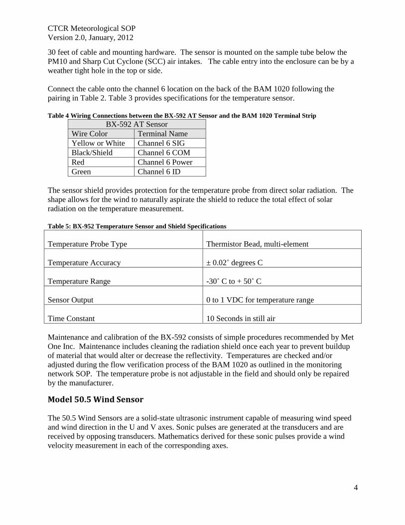
CTCR Meteorological SOP
Version 20 January 2012
4
30 feet of cable and mounting hardware The sensor is mounted on the sample tube below the
PM10 and Sharp Cut Cyclone (SCC) air intakes The cable entry into the enclosure can be by a
weather tight hole in the top or side
Connect the cable onto the channel 6 location on the back of the BAM 1020 following the
pairing in Table 2 Table 3 provides specifications for the temperature sensor
Table 4 Wiring Connections between the BX-592 AT Sensor and the BAM 1020 Terminal Strip
BX-592 AT Sensor
Wire Color Terminal Name
Yellow or White Channel 6 SIG
BlackShield Channel 6 COM
Red Channel 6 Power
Green Channel 6 ID
The sensor shield provides protection for the temperature probe from direct solar radiation The
shape allows for the wind to naturally aspirate the shield to reduce the total effect of solar
radiation on the temperature measurement
Table 5 BX-952 Temperature Sensor and Shield Specifications
Temperature Probe Type
Thermistor Bead multi-element
Temperature Accuracy plusmn 002˚ degrees C
Temperature Range -30˚ C to + 50˚ C
Sensor Output
0 to 1 VDC for temperature range
Time Constant
10 Seconds in still air
Maintenance and calibration of the BX-592 consists of simple procedures recommended by Met
One Inc Maintenance includes cleaning the radiation shield once each year to prevent buildup
of material that would alter or decrease the reflectivity Temperatures are checked andor
adjusted during the flow verification process of the BAM 1020 as outlined in the monitoring
network SOP The temperature probe is not adjustable in the field and should only be repaired
by the manufacturer
Model 505 Wind Sensor The 505 Wind Sensors are a solid-state ultrasonic instrument capable of measuring wind speed
and wind direction in the U and V axes Sonic pulses are generated at the transducers and are
received by opposing transducers Mathematics derived for these sonic pulses provide a wind
velocity measurement in each of the corresponding axes
CTCR Meteorological SOP
Version 20 January 2012
5
The 505 uses a microprocessor-based digital electronic measurement system to control the
sample rate and compute the wind speed and wind direction The sensor is factory calibrated and
requires no field calibration In the field the operation of the sensor can be quickly checked
using a combination of simple tests A zero chamber or bag is used to verify the zero reference
by covering the entire sensor or individual outputs are checked by blocking various
combinations of sensors
The sensor is designed for installation in a Model 3188 mounting and alignment fixture (Figure
1) This provides a mount for use on a horizontal frac34 inch IPS pipe boom The 3188 Sensor
Mounting Fixture includes a keyed bushing which will be adjusted for alignment to North
orientation enabling the sensor to be removed and replaced without realignment Three captive
machine screws are used to secure the sensor to the keyed bushing Review page 22 of the
operation manual (Appendix C) for a diagram of a top of tower installation
Orientation of the sensor to true north can be accomplished by following the instruction on page
8 of the operation manual and should be necessary only on setup To prevent birds from
perching on the sensors stainless steel wire deterrents are installed prior to securing to the
alignment fixture Safety precautions should be followed during this operation because the
deterrents are very sharp
The External Heater provides de-icing for the sensor arms and prevents the accumulation of ice
which might block the sonic elements The heater consists of a laminated material that is
wrapped around the four sensor arms and sonic sensor element housings Heater power is
supplied from a Met One Instruments power unit in a weatherproof box The heater is activated
at 38 degrees F and will keep the arms ice-free at temperatures down to below -20 degrees F
The connection information can be found in Appendix C of this manual
The temperature controller electronics box should be mounted no more than 5 feet from the
sensor using the U-bolts and cable supplied with the heater controller A two conductor cable
spans the distance from the heater controller to the heater power supply The power supply
fastened to the tower with the U-bolts provided and then plugs into a three prong 120 volt AC
receptacle
Follow the instructions on page 12 of the operations manual for details on connecting the data
cable to the data logger Several options are available depending on which connection is needed
The data cable from the sensor to the data logger should be secured to the boom and tower with
cable ties The two wind sensors differ in voltage output 0 to 25 volts at Nespelem and 0 to 10
volt at Inchelium This difference is important when configuring the data loggers at each site
Operation of the 505 is essentially automatic no specific sensor calibration is required The
sensor has been calibrated in a wind tunnel at the factory prior to shipment The sealed sensor
cannot be adjusted in the field and there are no replaceable parts To ensure that the recorder is
scaled properly the manufacture recommends that zero and span tests are performed after the
sensor is connected and operational
CTCR Meteorological SOP
Version 20 January 2012
6
Figure 1 Model 505 Wind Sensor Components
CTCR Meteorological SOP
Version 20 January 2012
7
A zero test requires the prevention of air movement across the sensor by covering the array A
plastic bag can be placed over the array using care not to contact the transducers or block the
sonic paths between transducers The bag should be spaced at least 2 above the transducers to
avoid sonic reflections which may affect readings The bag can be tied at the bottom with a tie
wrap or tape to prevent air movement from below the wind can deflect the bag causing air
movement inside With no air movement across the array the sensor should indicate 00 to 01
ms wind speed The wind direction output will wander to any value between 0 and 360 degrees
The sensor is designed to produce known default outputs if an object blocks the sonic signal path
between the transducers This feature is useful for verifying sensor operation and recorder
scaling For testing purposes the sonic path can be blocked by placing a finger (or any solid
object) on the face of one or more transducers
The outputs after blocking the transducers are shown in Table 6 below
Table 6 Span Test Outputs for Blocked Transducers
Wind Speed
Blocked Axis Serial Output Analog Output 0-10 V 0-25 V
North-South 100 ms 50 ms 100 V 250 V
East-West 100 ms 50 ms 100 V 250 V
Both 100 ms 50 ms 100 V 250 V
Wind Direction
Blocked Axis Serial Output Analog Output 0-10 V 0-25 V
North-South 10 degrees 10 degrees 003 V 007 V
East-West 160 degrees 160 degrees 044 V 111 V
Both 170 degrees 170 degrees 047 V 118 V
The testing of the transducers can easily be accomplished when the tower is tipped down for the
yearly inspection Table 7 lists the specifications for the wind sensor
Table 7 Model 505 Wind Sensor Specifications
Wind Speed Specifications
Range 0 to 50 msec
Accuracy plusmn 02 msec le 113 msec or plusmn 2 ge113 msec
Resolution 01 msec
Wind Direction
Range 0 to 360deg
Accuracy plusmn3deg
Resolution 1˚
CTCR Meteorological SOP
Version 20 January 2012
8
Operation
Sample Rate 5 per second
Data Output Rate 1 per second
Sonic frequency 200 KHz
Output Signals
Wind speed voltage 0-50 VDC
Wind direction voltage 0-50 VDC
RS-232 1200 to 192K Baud
Power requirement
Sensor 9-18 VDC 10 mA 12 VDC Average power
External Heater Option 15 VDC 50 Watts
Environmental
Maximum Measurement range 0 to 65 mls
Operating Temperature -40degC to +55degC no ice
Extended Temperature Range -50degC to +55degC with external heater
Physical
Weight 55 Ibs
Dimensions 1929in high 938in diameter
Model 083D Relative Humidity Temperature Sensor
The 083D-1-35 Sensor is an extremely accurate and sensitive relative humidity and temperature
sensor Response is linear with small hysteresis and negligible temperature dependence The
sensors are installed in a radiation shield before shipping The 73B radiation shield (Figure 2)
mounts on the opposite end of the boom from the 505 wind sensor on top the tower The
radiation Shields and cables have Mil Spec screw-on or twist-on cable connectors that are pre-
fitted by Met One The cable should be secured to the boom and tower with cable ties
The Relative HumidityTemperature Sensor has been calibrated at the factory and will not
change unless it is damaged Blow on the sensor for a quick check for operation the RH will
rise To check for reasonableness of operation compare the measurement with a local weather
service facility The reading will not be exactly the same but should be similar Compare the
temperature measurement to the delta Cal standard reading when conducting flow verifications
The sensor may need cleaning due to the accumulation of dust or other substances that will affect
measurements Turn off power to the sensor before attempting to clean and keep off until dry
Cleaning with distilled water will be adequate in most instances If extremely dirty or covered
with substance water will not remove isopropanol can be used Follow the instruction in the
operations manual to prevent damage to the sensor when cleaning with liquids
CTCR Meteorological SOP
Version 20 January 2012
9
Figure 2 Model 073B Radiation Shield
Table 8 Model 083D RH and Temp Sensor Specifications
Sensing Element Thin-film Capacitor
RH Range 0 - 100
Temp Range -50deg to +50degC
Response Time 15 seconds at 20degC
RH Accuracy plusmn2 RH between 10 and 100 RH
Temp Accuracy 01degC
Hysteresis For 0 to 100 to 0 excursion le 1
Temperature Coefficient plusmn004 per 1degC
Output 0 - 1 V full scale
Input Power 12V DC
Barometric Sensor 090D
The 090D (2632-1) uses an active solid-state device to sense barometric pressure with a range of
26 to 32 inches of mercury and a voltage output of 0 ndash 1 volt The sensor attaches to the tower or
other convenient location with a ldquoJrdquo bolt Orient the J box with the pressure inlet port facing
down Install the cable through the water tight fitting and connect as shown in Figure 2
CTCR Meteorological SOP
Version 20 January 2012
10
Figure 3 Installing the Barometric Sensor 090D Wiring
The sensor has been calibrated at the factory and will not change unless damaged No field
modification or calibrations can occur To check for proper operation compare to a local
weather station to see if the readings are reasonable The measurement will not be exactly the
same due to differences in elevation and measurement parameter absolute or normalized to sea
level This sensor measures absolute inches of mercury BP can also be checked when
conducting regular flow verifications or calibrations on the BAM 1020 The deltaCal standard
measures BP as millimeter (mm) or millibars (mb) and can be converted to inches mercury by
multiplying mm X 03937 and mb X 00295
Maintenance consists of inspecting the pressure inlet port for blockages and removing
obstructions if found If service or recalibration becomes necessary then send the sensor to the
manufacture
Rain Gauge 375 001 Inches This sensor measures precipitation on a continuous basis and is low-maintenance The tipping
bucket collects 001 inches of precipitation then tips and drains This triggers a switch closure
pulse that is counted The tipping bucket and rain gauge are heated to prevent accumulation of
snow and ice The sensor has been calibrated at the manufacture and should not require
adjustments after installation Mount the sensor level on a platform using the built in level and
three adjusting legs Follow the instruction in the operations manual (Appendix F) for complete
installation instructions A debris screen should be removed during the winter when snow will
accumulate
After installation manually actuate the tip bucket mechanism three times and confirm the tips
have registered on the data logger Inspect and clean the tipping buckets periodically and
physically tip to verify recording on the data logger If the sensor has been damaged or appears
to need calibration follow the instruction in the operations manual
Table 9 Model 375C Rainfall Sensor Specifications
Orifice 8 Inch Diameter
Calibration 01 Inches Rain per Switch Closure
Accuracy plusmn 1 at 1 to 3 inches per hour at 70 Fdeg
Switch Type Magnet and Reed
Mounting 3 Pad for 14 inch bolts
Dimensions 8 Inch Diameter
CTCR Meteorological SOP
Version 20 January 2012
11
Power Requirement 110 VAC
Weight 75 Pounds
Quality Control and Quality Assurance Quality Control (QC) and Quality Assurance measure are minimal due to the reliability and low
maintenance of the meteorological sensors employed The following table list all standards
used maintenance needed and actions If sensors exhibit characteristics outside of these
parameters the manufacturer will be contacted for instructions Records related to Meteorological
sensors will be tracked on the site log and summaries semiannually
Table 10 Meteorological Sensor Quality Control and Assurance Measures
Sensor Criteria Action
BX-596 ATBP Sensor
BP varies more than plusmn10 mm Hg from deltaCal Standard BAM 1020 Calibration Following SOP
Temperature varies more than plusmn2degC from deltaCal Standard BAM 1020 Calibration Following SOP
Sensor shield andor probe damaged Contact Met One for instructions
BX-592 Outside Temperature Sensor Volumetric Flow
Temperature varies more than plusmn2degC from deltaCal Standard BAM 1020 Calibration Following SOP
Temperature shield andor probe damaged Contact Met One for instructions
Model 505 Wind Sensor
Yearly zero test reading 00 to 01 ms wind speed
Contact Met One for instructions if greater than these readings
Yearly span test
Contact Met One for instructions if readings do not match those shown in Table 6
Heater not functioning Contact Met One for instructions
Relative HumidityTemperature
Sensor 083D
Yearly check for reasonableness Compare with local weather station
Yearly check for operation Blow on sensor and confirm RH rise
Barometric Sensor 090D Yearly inspection
Clean pressure inlet port for blockages when needed
Compare to deltaCal Standard Contact Met One for instructions if values do not compare reasonably
Rain Gauge 375 001 Inches
Yearly check for operation Manually tip bucket and confirm reading
Yearly check for level Use adjustment legs to level
Damage or bucket set screws loose
Follow instructions in operation manual for calibration
CTCR Meteorological SOP
Version 20 January 2012
12
Reference EPA Requirements for Quality Assurance Project Plans EPA QAR-5 Office of Environmental
Information Washington DC EPA240B-01003 March 2001
Guidance for Quality Assurance Project Plans EPA QAG5 Office of Environmental
Information Washington DC EPA240R-02009 December 2002
Guidance for Preparing Standard Operating Procedures (SOPs) EPA QAG-6 Office of
Environmental Information Washington DC EPA6000B-07001 April 2007
Met One Instruments Inc (2008) BAM 1020 particulate monitor operation manual Prepared by
Met One Instruments Inc Grants Pass OR BAM-1020-9800 Rev G
Standard Operating Procedure for the Continuous Measurement of Particulate Matter Monitoring
Sites Confederated Tribes of the Colville Reservation Air Quality Program August 2011
CTCR Meteorological SOP
Version 20 January 2012
13
Appendices
BX-596 ATBP SENSOR MANUAL
Met One Instruments Inc 1600 Washington Blvd Grants Pass Oregon 97526 Telephone 541-471-7111 Facsimile 541-541-7116
BX-S9G Sensor Manual - copy Copyright 2007 Met One Instruments Inc All Rights Reserved worldwide No part of this publication may be reproduced transmitted transcribed stored in a retrieval system or translated into any other language in any form without the express written permission of Met One Instruments Inc
Appendix A BX-596 ATBP Sensor Operation Manual
About this Manual
The BX-596 is an optional combination ambient temperature and barometric pressure sensor for use with the BAM-1020 particulate monitor The BX-596 sensor is a required accessory for all BAM-1020 configured to sample PM25 levels effective March 2007 The sensor provides ambient temperature and pressure data to the unit for actual (volumetric) flow control and flow statistics during the hourly sample cycle The BX-596 is only compatible with BAM-1020 firmware version 324 or later This manual describes the installation and operation of the BXshy596 sensor Refer to the BAM-1020 operation manual as needed
The BX-596-1 is an extended range version for extreme cold or high altitude environments
BX-59G TemperaturePressure Sensor Installed on a BAM-1020 Inlet Tube
Specifications
I
I I
I
I
I I
BX-59G Barometric Pressure Ambient Temperature Voltage Output o to 25 volts o to 25 volts
Range 525 to 825 mmHg -40 to +55 deg C Accuracy plusmn025 mmHg 25 C plusmn 15C above -30
10 Voltage 350 volts DC plusmn 02
BX-59G-1 Barometric Pressure Ambient Temperature i
Voltage Output o to 25 volts o to 25 volts Range 400 to 825 mmHg -50 to +50 deg C
Accuracy plusmn15 mmHg plusmn 15C full scale 10 Voltage 410 volts DC plusmn 02
BX-596-98DD Manua RevBdoc Page 1 of 4
Appendix A BX-596 ATBP Sensor Operation Manual
Installation and Setup
Ensure that the BAM-1020 is sited and installed properly per the instructions in the operation manual
During the installation process you will need to provide an access point for the BX-596 sensor cable to enter the shelter where the BAM-1020 is installed In some cases it is easiest to simply drill a 38 hole through the roof of the shelter about six inches away from the inlet tube then feed the cable through the hole and caulk around it to prevent leaks
There may be a better place to feed the cable into the shelter in some applications The BXshy902903 environmental shelters supplied by Met One have pre-formed access holes in the side to allow the sensor cable to be routed to the BAM-1020 Decide the best way to route the cable into the shelter The BX-596 comes with a standard 25-foot sensor cable Longer cables may be ordered if required
Remove the PM 10 head and PM25 cyclone from the top of the BAM inlet tube Attach the BXshy596 to the inlet tube (about 8 to 18 inches from the top) with the supplied U-bolt hardware Make sure that the sensor is level and tighten the U-bolt securely
Make sure the BAM-1020 is turned off then attach the sensor cable to the connector on the bottom of the BX-596 Route the loose end of the cable into the shelter and to the back of the BAM-1020 Coil up any excess length of cable Attach the cable to the back of the BAM as shown in the following table
I
BX596 ATBP Sensor Connections Wire Color Function BAM Terminal
Yellow A T Signal Output Channel 6 SIG BlackShield Ground Channel 6 COM Red +12 VDC Channel 6 POWER Green Auto 10 Signal 350V Channel 6 10 White BP Signal Output Channel 7 SIG
Reinstall the PM10 head and PM25 cyclone and seal around the cable hole with silicone if required
Operation
When the BAM-1020 is powered up with a BX-596 installed the unit will automatically sense the 10 voltage from the sensor and configure input channels six and seven to read and scale the outputs from the sensor Note The BX-596 sensor requires BAM-1020 firmware revision 320 or later The BX-596-1 extended range version requires BAM-1020 firmware revision 362 or later If the BAM firmware is not current enough then the BAM will not automatically identify and scale the sensor
Appendix A BX-596 ATBP Sensor Operation Manual
Turn ON the BAM-1020 and perform a calibration of the BX-596 Note The calibration is performed in the TESTgt FLOW screen which will not be available unless the FLOW TYPE is set to ACTUAL in the SETUPgt CALIBRATE screen You will need a reference standard measurement for ambient temperature and barometric pressure
MULTIPOINT FLOW CALIBRATION TARGET BAM STD
ltCALgt ~~~ 238 238 C BP 760 760 mmHg
FLOW 1 150 150 150 LPM FLOW 2 183 183 183 LPM FLOW 3 167 167 167 LPM
CAL NEXT DEFAULT EXIT
1 Enter the TESTgt FLOW menu as shown above The nozzle will lower automatically when this screen is entered The BAM colurnn is what the BAM-1020 measures for each parameter and the STO column is where you will enter the correct values from your reference standard The ltCALgt symbol will appear next to the parameter selected for calibration
2 Measure the ambient temperature with your reference standard positioned near the BXshy596 sensor Enter the value from your reference standard into the STO field using the arrow keys Press the CAL hot key to correct the BAM reading The BAM and STO values should now be the same
3 Press the NEXT hot key to move the ltCALgt indicator to the BP field and repeat the same steps for barometric pressure
The DEFAULT hot key can be pressed to reset the user calibration from the selected parameter and replace it with a factory setting The DEFAULT calibration should be fairly close in most cases
The BX-596 sensor is almost always calibrated as part of a BAM-1020 flow calibration Always calibrate the AT and BP channels before calibrating the flow channels as the flow rate is affected by the temperature and pressure of the ambient air
The 8X-596 temperature output may also be checked in an ice bath The ice bath test is usually never done except in some cold weather environments First calibrate the sensor at ambient temperature then use the following steps
1 Remove the stop screw from the bottom of the mounting bracket so that the electronics module is free to rotate Rotate the module counter-clockwise until it disengages from the keyhole slots and comes free from the radiation shield
2 The sensor comes with an 18 inch long ice bath extension harness This may be used to allow the temperature bead to reach the ice bath if necessary Carefully unplug the black temperature bead assembly from the top of the electronics module and install the harness between the bead and the module
3 Insert the temperature bead into the ice water bath along with your reference sensor Avoid immersing the bead assembly past the connector
Appendix A BX-596 ATBP Sensor Operation Manual
4 Allow the bead to equilibrate then compare the AT reading in the TESTgt FLOW screen to your reference sensor The readings should match within plusmn15 degrees C for the BXshy596-1 extended range sensor Note The tolerance for the regular BX-596 standard range sensor is plusmn 25 C in temperatures below -30C
5 Remove the ice bath harness and reassemble the sensor
During operation of the BAM-1020 the output from the BX-596 can be viewed from the main flow statistics screen or the OPERATE screens See the BAM-1020 manual
JI -~J
1 1~
i gt
-- --- shyv_
Ice Bath Extension Harness
Maintenance The BX-596 is designed to be low-maintenance easy to access and resistant to harsh environments There are only a few maintenance items for the sensor besides routine calibration checks
bull Remove the bottom cover and make sure that the four holes in the cover plate are clear and have not been obstructed by insects or debris These holes allow the air pressure to equilibrate inside the sensor for the barometric pressure reading Clean the inside of the electronics enclosure every 12 months or as needed
bull Clean the radiation shield assembly at least once per year Dirty shields reflect away solar radiation less efficiently
bull The circuit board is not intended to be removed or serviced by the customer bull The black temperature bead assembly may be replaced if the bead becomes damaged
The assembly simply plugs into the top of the electronics module The sensor will need to be recalibrated any time the temperature bead is replaced
Technical Support
Should you still require support after consulting your printed documentation we encourage you to contact one of our expert Technical Service representatives during normal business hours of 700 am to 400 pm Pacific Standard Time Monday through Friday In addition technical information and service bulletins are often posted on our website Please contact us and obtain a Return Authorization (RA) number before sending any equipment back to the factory This allows us to track and schedule service work and expedite customer service
Phone (541)471-7111 Fax (541)471-7116 E-Mail servicemetonecom Web wwwmetonecom
Mail Technical Services Department Met One Instruments Inc 1600 NW Washington Blvd Grants Pass OR 97526
Appendix A BX-596 ATBP Sensor Operation Manual
warranty
Products manufactured by Met One Instruments Inc are warranted against defects in material and workmanship for a period of one (1) year from the date of shipment from the factory Offered products not manufactured by Met One Instruments Inc will be warranted to the extent and in the manner warranted by the manufacturer of that product
Any product found to be defective during the warranty period will at the option of Met One Instruments Inc be replaced or repaired In no case shall the liability of Met One Instruments Inc exceed the purchase price of the product
This warranty may not apply to products that have been subject to misuse negligence accident acts of nature or that have been altered or modified other than by Met One Instruments Inc Consumable items such as bearings and batteries are not covered under this warranty
Other than the warranty set forth herein there shall be no other warranties whether expressed implied or statutory including warranties of fitness or merchantability
Service
Ary product being returiled to Met One Instruments In for service repair or calibration must be assigned a return authorization (RA) number Please call (541) 471-7111 or (972) 412-4715 for an RA number and shipping instructions
Products manufactured by Met One Instruments Inc that are returned for service repair or calibration are warranted against defects in material and workmanship for ninety(90) days from date of shipment under the same conditions as stated above
999
Appendix A BX-596 ATBP Sensor Operation Manual
Temperature Probe amp Shield Model BX-592
Operation Manual BX-592-9800
1600 Washington Blvd Regional Sales amp Service Grants Pass Oregon 97526 3206 Main St Suite 106
Met One Instruments
Telephone 541-471-7111 Facsimile 541-541-7116
Rowlett Texas 75088 Telephone 972-412-4715 Facsimile 972-412-4716
Appendix B BX-592 Temperature Probe and Shield Operation Manual
Model BX-592 Temperature Probe amp Shield Operation and Installation Manual
INTRODUCTION The Model BX-592 is a temperature probe and shield for use with the BAM-1020 particulate analyzer The BX-592 is used specifically with the BX-962 Volumetric Flow Control System used on the BAM-1020 This sensor provides temperature measurement of the outside air used to determine the temperature correction value as part of the volumetric flow calculation The sensor is designed to be connected directly to one of the analog input channels of the BAMshy1020 The BX-592 is used when there is no other source of analog temperature output from an existing temperature system at the owners location The BX-592 includes 30 ft of cable as well as a mounting adapter that attaches to the inlet tube of the BAM-1020
INSTALLATION The BX-592 is installed outside near the intake of the BAM-1020 particulate analyzer Mounting hardware is provided for direct mounting on the BAM-1020 inlet tube as shown in figure 10 Attach the temperature probe and shield to the horizontal bar using the clips on the top of the temperature shield Push the shield up onto the horizontal bar and press the grey plastic clips together until you hear the snap of the retainer locking inplace
The fitting on the mounting arm should be mounted in a convenient place near the top of the inlet tube and out of the way of the supports used to hold the inlet tube in place Tighten the set screws on the mounting adapter to hold it in place on the inlet tube The horizontal bar can be moved as necessary to mount the shield in a suitable location near the inlet tube and the PM-10 or PM-25 inlet assembly
The cable from the sensor can then be run down through the roof of the shelter or building so that it can be connected to the sensor input channel terminal block on the back of the BAMshy1020 unit
Figure 1 Temperature Sensor Installation
BX-592 Manual 31JAN2001 2
Appendix B BX-592 Temperature Probe and Shield Operation Manual
The sensor input connection should be made at sensor location six This input channel is the one used for any external temperature analog input used for the temperature correction input required by the volumetric flow controller
The BX-592 Temperature Sensor and Shield provides a special ider1tification output signal that is used by the BAM-1020 to determine what type of sensor is connected to the BAM as well as determine what the range of the temperature sensor The electrical connections to the BAMshy1020 can be see in Figure 2 Be sure that the color code of the individual wires of the cable is followed so that the sensor is not connected incorrectly to the BAM-1020 There are four wires which are connected to the four terminals of the analog inputs at the back of the BAM unit
IO~=== laquo) SIG ~2P-~~~WHTd COM ~~BLK ----~_4z ~ PWR ~2P-REO ----- I I 0 ~d)J-GRN --shyUL=== ~
SIG ~
Figure 2 Sensor Connections to BAM
Figure 2 shows the connections from the BX-592 Temperature Sensor and Shield to the BAMshy1020 Particulate Analyzer Be sure that the temperture sensor cable is connected to channel 6 of the BAM-1020 otherwise the voltage output of the sensor will not be able to be used as the temperature reference of the volumetric flow controler
For correct operation of the volumetric flow control option BX-961 the BAM-1020 must be programmed for volumetric flow operation This is done from the SETUP then CALIBRATE and then FLOW TYPE screen The default is metered flow and will need to be set for volumetric flow for tt1ts option to work correctly See the BAM-1020 Manual section 414 for information on the Calibrate Screen and in section 63 for information on the field calibration of the flow system
SPECIFICATIONS The following are the specifications of the BX-592 Temperature Sensor and Shield These are subject to change as determined by Met One Instruments Inc The shield of the BX-592 provides protection of the temperature probe from errors that are caused by direct solar radiation The shape allows for the wind to naturally aspirate the shield to reduce the total effect of solar radiation on the temperature measurement
Temperature Probe Type Thermistor Bead multi-element
Temperature Accuracy
Temperature Range
Sensor Output o to 1 VDC for temperature range
Time Constant 10 Seconds in still air
BX-592 Manua13IJAN2001 3
Appendix B BX-592 Temperature Probe and Shield Operation Manual
The shield is mounted from the top of the shield using two snap clamps designed for a 1 diameter tube or a IPS Pipe The mounting adapter and a short boom are provided for attachment to the inlet tube of the BAM-1020
MAINTENANCE amp CALIBRATION The temperature probe and shield require no specific maintenance other than normal cleaning of dirt and dust to prevent the degredataion of the reflectiveness of the shield If there is any build up of materials inside the shield they should be cleaned out so that there is a free path for air flow around the temperature probe
On a regular basis the output of the temperature probe displayed on the screen of the BAMshy1020 should be checked against a reference thermometer to be sure that the BX-592 is providing accurate information for the calculation of volumetric flow There are no adjustments inside the temperature probe and any repairs should be handled by the factory
Before returning a faulty probe the factory should be contacted a RA (Return Authorization) should be obtained and the problem noted on the RA This will insure that the repairs are made quickly and returned for installation
TROUBLE SHOOTING
Symptom Identify Problem Solution Incorrect Temperature indicated on BAM Display
Verify that connections to the rear panel of the BAM are correct and to channel 6
Change wiring to follow diagram as indicated in figure 2 of this manual
From setup menu channel Change settings from parameters screen verify that MANUAL Mode to Auto ID channel 6 is set for Auto ID mode for probe to work and not in MANUAL Mode correctly Examine output of BX-592 to Using a volt meter measure verify that it has the correct voltage between the black and voltage output for the current white wires 0-1 volt is ambinet temperature equivalent to -30 to 50
degrees C Le 21degC =637 volts If this is not correct return probe for repair
Volumetric Flow Control is not operating
Go to the Setup then Calibrate screen menu and verify that the flow type is set to volumetric and not metered
Default setting is for metered it will be necessary to change setting to volumetric flow type
Examine rear of BAM-1020 and see if there is a flow adjusment knob on the back of the unit right above the vacuum line
If there is a knob here it is most likely that volumetric flow control is not installed on this unit Contact Met One Instruments for advice
Volumetric flow value does not match audit flow meter connected to BAM
From setup menu select flow and examine the current measured flow value of the BAM
Recalibrate the BAM flow meter using the proceedure in the manual section 63 Field Calibration of Flow System
Verify that the audit instrument being used has been calibrated for volumetric flow monitoring
Adjust flow audit device for correct measurement of volumetric flow
BX-592 Manual 3IJAN200 1 4
Appendix B BX-592 Temperature Probe and Shield Operation Manual
For any other specific problems with the BX-592 or the Volumetric Flow Option BX-961 contact the factory
Met One Instruments Inc 1600 NW Washington Blvd Grants Pass Oregon 97527
(541) 471-7111 Voice (541 ) 471-7116 FAX
service metonecom e-mail
Visit our web page at httpwwwmetonecom
BX-592 Manual 31JAN2001 5
Appendix B BX-592 Temperature Probe and Shield Operation Manual
MODEL 505 WIND SENSOR
OPERATION MANUAL Document No 505-9800
1600 Washington Blvd Grants Pass Oregon 97526
Met One Telephone 541-471-7111 Instruments Facsimile 541-541-7116
Regional Sales amp Service 3206 Main St Suite 106 Rowlett Texas 75088 Telephone 9724124715 Facsimile 972-412-4716
505-9800 Rev Edoc
Appendix C Model 505 Wind Sensor Operation Manual
Copyright Notice
505 Sonic Wind Sensor Manual
copy Copyright 2005 Met One Instruments Inc AI Rights Reserved Worldwide No part of this publication may be reproduced transmitted transcribed stored in a retrieval system or translated into any other language in any form by any means without the express written permission of Met One Instruments Inc
Technical Support Should you require support please consult your printed documentation to resolve your problem If you are still experiencing difficulty you may contact a Technical Service representative during normal business hours-730 am to 400 pm Pacific Standard Time Monday through Friday
Voice (541) 471-7111
Fax (541) 471-7116
E-Mail servicemetonecom
Mail Technical Services Department Met One Instruments Inc 1600 Washington Boulevard Grants Pass OR 97526
505-9800 Rev E Page 2
Appendix C Model 505 Wind Sensor Operation Manual
TABLE OF CONTENTS 1 GENEAAL INFORIIATION 5
2 INSTALLATION 5
21 LTNPACKlNG 5 22 PREPARATION 5 23 SENSOR SITING 6
Figure 2-1 Siting Wind Instroments 6 24 ORIENTATION WITH FIXTURE 7
Figure 2-2 Orientation Fixture 7 25 ORIENTATION WITHOUT FIXTURE (SEE FIGURE 2-3 AND 2-4) 8 26 EXTERNAL HEATER 8
Figure 2-3 505 Wind Sensor Components 9 Figure 2-4 Alignment aSensor to Troe North 10
27 INSTALLATION OF AVERY DETERRENTS 11 Figure 2-5 InstallatIOn ofAviary Delerrents I
28 CONNECTIONS TO RECORDING ELECfRONICS 12
Figure 2-7 Factory Standard Analog amp Rf-232 Output Connections (Cable 9574 wi Differential Amplifier
Figure 2-8 Factory Custom SDI-12 Output Connections 3
Figure 2-6 Amplifier (9573) attached to Cable (9574) and wiring in box 12
9573) 12
Figure 2-9 Factory Custom RS4221485 Output Connections 13 28 SIGNAL OUTPUTS ANALOG RS-232 ANDSDI-12 13 29 SIGNAL OUTPUTS - RS422 AND RS485 14
3 OPERATIONAL CHECK-OUT AND CALmRATION 14
31 GENERM 14 32 RECORDING ELECTRONICS 14 33 ZERO TEST 14 34 SPAN TEST 14
4 MAINTENANCE AND TROlTBLESHOOTING 15
41 GENERAL MAlNTENANCE SCHEDULE 15 42 TROlTBfJESHOOTING 15
5 TIIEORY OF OPEAATION 16
51 SPEED OF SOUND IN AlR 16 52 SPEED OF S()UND PRINCIPLE 16 53 CALCULATION OF THE WIND VELOCITy 16
6 SPECIFICATIONS 17
FIGURE 6- 505 Wind Sensor Outline Dimensions 18
APPENDIX A - WIND DIRECTION SENSOR ORIENTATION 19
APPENDIX B - WIND SENSOR MOUNTING OPTIONS 22
APPENDIX C - HEATER CONFIGURATION AND WIRING 23
APPENDIX D - RS2J2 COMMAND SET 25
GENERAL PROTOCOL 25
1 RS-2J2 DATA OUTPUT PROTOCOL 25
11 ERROR CODE 26
2 USER COMMAND SET _ 27
21 L8-VERBOSE CONTROL OF RS-232 PARAMETER LABELS 27
505-9800 Rev E Page 3
Appendix C Model 505 Wind Sensor Operation Manual
22 MS-MAxLMUM FULL SCALE WIND SPEED 27 23 SU-WINO SPEED UNITS 27 24 QU-QUlT 27 25 SB-SERIAL BAUD RATE 28 26 ST-SERIAL TRIGGER (RS-485 ONLy) 28 27 IT-SONIC TEMPERATURE 28 28 VN-VERSION NUMBER 28 29 VS-FULL SCALE ANALOG OUTPUT VOLTAGE FOR WINO SPEED Ai~O WINO DIRECTION 28
505-9800 Rev E Page 4
Appendix C Model 505 Wind Sensor Operation Manual
MODEL 505 WIND SENSOR OPERATION MANUAL
1 GENERAL INFORMATION
The Met One Instruments Model 505 Wind Sensor is a solid-state ultrasonic instrument capable of measuring wind speed and wind direction in the U and V axes Sonic pulses are generated at the transducers and are received by opposing transducers Mathematics derived for these sonic pulses provide a wind velocity measurement in each of the corresponding axes
The 505 uses a microprocessor-based digital electronic measurement system to control the sample rate and compute the wind speed and wind direction The sensor is factory calibrated and requires no field calibration In the field the operation of the sensor can be quickly checked using a combination of simple tests A zero chamber or bag is used to verify the zero reference by covering the entire sensor or individual outputs are checked by blocking various combinations of sensors
The 505 provides are variety of outputs to suit the connection requirements of the user Standard outputs are voltage and RS-232 SDI-12 and RS422485 outputs are configured at the factory
2 INSTALLATION
21 UNPACKING
Carefully remove the sensor from its shipping container and inspect it for damage Referring to the packing list check for shortages Any claims for damages should be filed promptly with the carrier
The sensor is a precision electromechanical transducer Always handle it with care exercising particular caution to ensure that the instrument is not subjected to side loading shock or other abuse After initial inspection keep the sensor in its shipping container for protection until actual installation
22 PREPARATION
For accurate measurements the sensor mount must be rigid with little or no movement from the wind The sensor is designed for installation in a Model 3188 mounting and alignment fixture This provides a mount for use on a horizontal IPS pipe (105- 00) boom Mounting information and diagrams can be found in Appendix B of this manual
The 3188 Sensor Mounting Fixture includes a keyed bushing which will be adjusted for alignment to North orientation This enables the sensor to be removed and replaced without requiring realignment Three captive machine screws are used to secure the sensor to the keyed bushing
If a temperature shield such as the Model 0738 is to be used in the configuration the Model 1539-4 Arm and 1552 Mount is recommended These parts provide the necessary mounting for a vertical mast of 0 IPS pipe (105 OD) This same configuration can also be used to mount other sensors as well as providing a way to mount the sensor on a vertical mast (See Appendix B for Mounting Details)
505-9800 Rev E Page 5
Appendix C Model 505 Wind Sensor Operation Manual
23 SENSOR SITING
The primary objective of instrument siting is to place the instrument in a location where it can make precise measurements that are representative of the general state of the atmosphere in that area Because most atmospheric properties change dramatically with height and surroundings certain somewhat arbitrary conventions must be observed so that measurements can be compared
lOT
Figure 2-1 Siting Wind Instruments
The standard exposure of wind instruments over level open terrain is 10 meters above the ground (WMO 1971) however optimum measurement height may vary according to data needs Open terrain is defined as an area where the horizontal distance between the wind sensor and any obstruction is at least ten (10) times the height of that obstruction An obstruction may be man-made (such as a building) or natural (such as a tree) (See Figure 2-1)
The wind instrument should be securely mounted on a mast that will not twist rotate or sway If it is necessary to mount the wind instrument on the roof of a building it should be mounted high enough to be out of the area in which the airflow is disturbed by the building This is usually 15 times the height of the building above the roof so that it is out of the wake of the obstruction This is not a good practice however and should only be resorted to when absolutely necessary
Wind instruments are best sited when they are used on towers The tower should be located in an open level area representative of the area under study Towers should be of the open grid type of construction such as is typical of most television and radio broadcast towers Enclosed towers stacks water storage tanks grain elevators cooling towers and similar structures should not be used
Wind instruments should be mounted above the top of the tower on booms projecting horizontally out from the tower If a boom is used it should support the sensor at a distance equal to minimum of twice or at best three times the maximum diameter or diagonal of the tower away from the nearest point on the tower On large towers with large verticals it may be best to place the sensor at least 5 tower leg diameters from the tower leg The boom should project into the direction which provides the least distortion for the most important wind direction For example a boom mounted to the east of the tower will provide least distortion for north or south winds
505-9800 Rev E PageS
Appendix C Model 505 Wind Sensor Operation Manual
Weather sensors are sensitive to direct or nearby lightning strikes A well-grounded metal rod or frame should be placed above the sensor installation In addition the shield on the signal cable leading to the translator must be connected to a good earth ground at the translator end and the cable route should not be vulnerable to lightning
24 ORIENTATION WITH FIXTURE
The Orientation Fixture Model 705 is used for very accurate positioning of the 505 sensor with respect to a benchmark or other object that can be visually obselVed If a compass is used to establish a benchmark the reading should be taken away from heavy metal objects which can affect the reading and should be corrected for declination of the magnetic north pole The benchmark is set to true north of the sensor site Information on determining true North can be found in Appendix A of this manual
The fixture contains a telescopic sight with crosshairs and includes a keyed base identical to that on the sensor The fixture is specifically designed for use with the 3188 Sensor Mounting Fixture The base of the fixture is keyed so that the object lens of the sight assumes the same position as the north side of the sensor
Before orienting the sensor ensure that it is vertical and adjust the cross arm as necessary Orientation of the sensor is then performed with the fixture installed on the cross arm in place of the sensor (The three screws in the base of the fixture must be tightened to ensure proper orientation in the cross arm) Loosening the three setscrews on the side of the sensor mount allows free rotation of the keyed bushing and orientation fixture The ring and fixture are then rotated to position the benchmark in the center of the sight crosshairs The sight can be tilted as necessary by loosening the slotted screw on the side of the fixture The set screws are then tightened the fixture removed and the sensor installed in its place The sensor is now oriented for zero (north) wind direction signal output when the wind is from north
OSIECTlENS
Figure 2 2 Orientation Fixture
The electrical connector on the bottom of the sensor should be properly mated to the cable connector and the three captive screws on the base of the sensor should be tightened
When using the orientation fixture assure that the two-piece mounting assembly is properly aligned The upper half of the assembly contains a horizontal peg which must seat in the vshynotch located in the lower half The knurled knob on the lower half is used to secure the two sections and should be tight
505-9800 Rev E Page 7
Appendix C Model 505 Wind Sensor Operation Manual
25 ORIENTATION WITHOUT FIXTURE (See FIGURE 2-3 and 2-4)
Establish a True North benchmark See Appendix A for aids to determine True North This should be a point directly north from the sensors mounted location This point should allow easy access so that a person may sight the sensor with a spotting telescope If a compass is used to establish a benchmark the reading should be taken away from heavy metal objects which can affect the reading and should be corrected for declination of the magnetic north pole The benchmark is set due north of the sensor site
One person is located at True North benchmark equipped with a spotting scope A second person is located at the sensor The sensor alignment may be established as follows
A Install the sensor into the alignment bushing and secure with the two setscrews under the 3188 Alignment Fixture Keep the three setscrews around the ring of the fixture loose so that the ring can be rotated into position
B Turn the sensor so that the sensor paints to the North benchmark Tighten the 3 setscrews and recheck align ment
C Connect the 9574-cable assembly to the sensor Secure cable to boom with cable ties or tape to prevent damage
D The sensor can be removed without requiring realignment at any time Simply remove the sensor The alignment bushing remains proper1y oriented in the fitting
26 EXTERNAL HEATER
The Optional External Heater provides de-icing for the sensor arms and prevents the accumulation of ice which might block the sonic sensor elements The heater consists of a laminated heater material that is custom designed and wrapped around the four sensor arms and sonic sensor element housings The heater controller requires 15 to 24 VACNDC at approximately 4-5 amps at startup There are jumper connections on the controller board for the selection of power source The controller is normally provided with the jumpers not installed This is for 24 volts AC operation of the heaters Heater power can be supplied from a power transformer or a Met One Instruments supplied power unit in a weatherproof box The proportional controlled heater uses maximum current at start-up and power requirement goes down as the sensorheater reaches stability The heater is activated at 38 degrees F and will keep the arms ice-free at temperatures down to below -20 degrees F The connection information can be found in Appendix C of this manual
The temperature controller electronics box should be mounted no more than 5 feet from the sensor using the cable supplied with the heater controller The power cable should be of minimum 16 AWG wire and cable length should be at a minimum to prevent power loss due to cable resistance at the 4-amp power requirement
505-9800 Rev E Page 8
Appendix C Model 505 Wind Sensor Operation Manual
MODEL 505 WINO SENSOR
NORTH SCREWPIN ____~~--
THIS SIDE TO FACE SOlTTH LABEL
NORTH SLOT HOLE~middot-c-lIIo-
SET SCREWS (3 EA FOR SECURING
KEYED BUSHING TO HORTH ORIENTATION
(7164- ALLEN KEY)
Figure 2-3 505 Wind Sensor Components
Page 9 505-9800 Rev E
Appendix C Model 505 Wind Sensor Operation Manual
SOUTHSIDE SENSOR TRANSDUCER SHOULD BE SEEN EaUALLY DIVIDED
BY NORTHSIDE (NEAR) ARM
Figure 2-4 Alignment of Sensor to True North
505-9800 Rev E Page 10
Appendix C Model 505 Wind Sensor Operation Manual
27 INSTALLATION OF AVERY DETERRENTS
To prevent birds from entering the pathway between the sensors a vertical stainless steel rod is located in the center of the sensor array_ To keep birds from perching on the sensors stainless steel wire aviary deterrent need to be installed on the sensor prior to installation in the fixture
NOTE The stainless steel wires used for the aviary deterrents are very sharp The wire is spring steel and there s the possibility that it could slip off during the installation Use care
when installing the aviary deterrent and be careful after installation
PROTECTIVE GLASSES SHOULD BE WORN DURING INSTALLATION
Installed A viarv Deterrents
area
AVIARY DETERRENTS bull PIIIih ends IowaIds eoch ltlttler lil qgten up
spring d1amccr bull Slide owr lranllducer 10 mounIing llIII bull ~6l as requRd 60 that avlary
delemK1N are pointed ~
MOUNTING AREA
Figure 2-5 Installation of Aviary Deterrents
WARNING If the aviary deterrents are not properly installed The sensor may experience signal degradation Install as shown DO NOT allow for the spring section of the aviary deterrent to contact the transducer portion of the sensor array_
505-9800 Rev E Page 11
Appendix C Model 505 Wind Sensor Operation Manual
28 CONNECTIONS TO RECORDING ELECTRONICS
Route the cable to the data-recording device Secure the cable with cable ties or tape The 9574shycable assembly contains 7 wires and a shield Typical wiring hookup is shown in the figures below Actual wiring will depend upon the version of the sensor To determine which of the three connections drawings apply examine the cable part number at both ends of the cable
Cable type 9574 includes the 9573 Differential Amptifier it is located at the end of the cable opposite the sensor connector The amplifier provides high immunity to any noise that might be picked up the sensor cables It is recommended that this cable with amplifier be used whenever connected to a single ended input recorder If necessary to remove the differential amplifier a wiring diagram has been included in the top of the small amplifier enclosure A small screwdriver is provided for use on the small terminal screws on the PC Board of the 9573 Amplifier Be sure that the connection color codes are followed so that no wiring error occurs See below
Warning If you are connecting this 505 to an older 3155-cable assembly and are using the black wire as signal common disconnect it because it will short out the RS-232 transmitter No damage will occur to the circuit but the 505 current consumption will increase by 20 rnA
TO SONIC
~ n 0 SHLD (WTIBN) +12Y(Wiri) 0 0 NIC wo oOt-(RpoundD 0 0 GND(GRN) WD 0lIT~ (OAN) 0 0 ncD(8LK) W8 ~+(BLU) 0 0 RXC(IRN) NC 0 0 WSIN+(BW) RXD(8fCN) 0 0 NIC TXDl8LJC) 0 0 WDW+(RED) OND(GRN) 0 0 WDIN-(ORN) NIC Omiddot 0 +12V(WtfT) SHLD (WTIBN) 0 J1 r-
TO DATALOGGIR
Figure 2-6 Amplifier (9573) attached to Cable (9674) and wiring in box
Sensor Common
Power Common WHITE
RED
+12V Power
BROWN RXRS-232 BLACK TXRS-232
Wind Direction Voltage BLUE OR YELLOW Wind Speed Voltag~
Shield WHITEBROWN
Figure 2-7 Factory Standard Analog amp RS-232 Output Connections (Cable 9574 wI Differential Amplifier 9573)
505-9800 Rev E Page 12
Appendix C Model 505 Wind Sensor Operation Manual
o NG[ GREEN WHITE
BROWN
aLACK
REO
BLUE OR YEllOW
Sensor Common
Power Common
+12VPower
Not Used
Not Used
Not Used SOI-12 Output
Shield WHITEBROWN
Figure 2middot8 Factory Custom SDI~12 Output Connections
ORANGE
RED
Sensor Common GREEN Power Common WHITE +12V Power
BROWN RX f
BLACK RX shy
TX+ BLUE OR YELLOW TX-
Shield WHITEBROWN
Figure 2-9 Factory Custom RS4221485 Output Connections
28 SIGNAL OUTPUTS - AnalogJ RS-232 and 501-12
The standard configuration of the sensor provides for a voltage outputs for wind speed and direction as well as RS-232 Data The default output voltage is 10 volts full scale for 50 meterssecond and 360 degrees of direction Alternate full-scale values can be changed by using the RS-232 command set discussed in Appendix O The R8-232 output occurs every second in the format S sssS 0 ddd ltcrgtltIfgt where ssss is the wind speed value up to 9999 and the direction ddd up to a value of 360 RS-232 output is at 9600 baud 8 data bits 1 stop bit and no parity
As an option an output of 801-12 Data from the sensor is available In this configuration it is the only available output and is in the format +ssss+ddd ltcrgtltlfgt The same values for sssS and ddd as the RS-232 format are output The 801-12 handshake is per the 801-12 specifications and format In this configuration the RS-232 output or analog output is no longer available from the sensor
505-9800 Rev E Page 13
Appendix C Model 505 Wind Sensor Operation Manual
29 SIGNAL OUTPUTS - RS422 and RS485
In this configuration the sensor has no analog outputs (see diagram Factory Custom RS422RS485 Output Connections The correct sensor cable for this configuration is part number 3379
The default serial trigger (sensor address) is 1 After receiving 1 the sensor will return wind speed and wind direction in the same format as with RS232 (S sSSs D ddd ltcrgtltlfraquo
To use the RS232 Command Set defined in Appendix 0 the sensor must first be put into Terminal Mode by sending (three exclamation points) The serial trigger is not used in this case and there must be only one sensor connected on the serial buss The sensor will return when in Terminal Mode and will then accept RS232 commands The au (quit) command will take the sensor out of Terminal Mode and return it to normal operating mode
3 OPERATIONAL CHECK-OUT AND CALIBRATION
31 GENERAL
Operation of the 50S is essentially automatic and no specific sensor calibration is required for normal operation The sensor has been calibrated in a wind tunnel at the factory prior to shipment
32 RECORDING ELECTRONICS
The sensor may be connected to a variety of data recorders and translators Standard wind speed range is O-SO mls and wind direction range is 0-360 degrees Standard output voltage is 0-10V with 0-2SV and O-SOV as available options Refer to the calibration certificate supplied with the sensor to determine the actual output
To ensure that the recorder is scaled properly it is recommended that zero and span tests are performed after the sensor is connected and operational
33 ZERO TEST
A zero test requires no air movement across the sensor array so a means of covering the array is needed A plastic bag can be placed over the array using care not to contact the transducers or block the sonic paths between transducers The bag should be spaced at least 2 above the transducers to avoid sonic reflections which may affect readings The bag can be tied at the bottom with a tie wrap or tape to prevent air movement from below Keep in mind that wind can defrect the bag causing air movement inside
The preferred method is to use a box insulated with foam to prevent reflections and spaced so that the top is at Jeast 2 above the transducers Again the bottom should be sealed around the sensor to isolate the array from ambient air movement
With no air movement across the array the sensor should indicate 00 to 01 ms wind speed The wind direction output will wander to any value between 0 and 360 degrees
34 SPAN TEST
The sensor is designed to produce known default outputs if an object blocks the sonic signal path between the transducers This feature is useful for verifying sensor operation and recorder scaling For testing purposes the sonic path can be blocked by placing a finger (or any solid object) on the face of one or more transducers
505-9800 Rev E Page 14
Appendix C Model 505 Wind Sensor Operation Manual
NOTE The following table defines the sensor outputs with blocked paths
Wind Speed Blocked Axis Serial Output North-South 100 mls East-West 100 mls 80th 100 mls
Analog Out~ut 50 mls 50 mls 50 mls
D-10V 100V 100V 100V
0-2SV 250V 250V 2S0V
O-SOV 500V SOOV SOOV
Wind Direction Blocked Axis Serial Output Analog Output D-10V 0-25V D-50V North-South 10 Deg 10 Deg 003V 007V 014V East-West 160 Deg 160 Deg O44V 111V 222V Both 170 Deg 1700eg 047V 118V 236V
4 MAINTENANCE AND TROUBLESHOOTING
The 50S sensor is sealed and there are no replaceable parts contained therein The sensor does not require periodic calibration and there are no internal adjustments that can be made
41 GENERAL MAINTENANCE SCHEDULE
12-24 month intervals
The Model 505 Wind Sensor should be inspected periodically for physical damage to the sensor array assembly cable and cable connections Inspect all transducers to be sure they are securely fastened
Schedule based on average to adverse conditions
42 TROUBLESHOOTING ------ --shy--=-----------------==-----~~---- ----~-~-~~~~~~---~-----~ ----~~~~~~~--
~________~piom _~ __ ____ _____ ~~o~babl~9_C1l1~~_~___ ~__+_-_-A-ct-io-n-to-R-eL-pa_ir__---i
Wind Speed output goes to full Blocked pathway 1 - Check path and clear scale
Failed sensor 2 - If clear contact factory for Return Authorization to repair sensor
Wind Speed output high but not Common mode voltage 1 - Replace cable with part full scale number 9574 (with 9573
differential-to- single-ended converter)
supply 2 - Use 3379 cable and power sensor with isolated power separate from recorder power supply
inputs 3 - Use 3379 cable and connect sensor signals to differential on recorder
505-9800 Rev E Page 15
Appendix C Model 505 Wind Sensor Operation Manual
5 THEORY OF OPERATION
51 SPEED OF SOUND IN AIR
The speed of sound in still air can be measured accurately between two points a few centimeters apart by two ultrasonic transducers set at that distance The resulting speed of sound is a known function of the air temperature and composition
The speed of sound waves in an ideal gas may be written
where R is the universal gas constant (083134 mJmol K) T is the temperature in Kelvin M is the molecular weight (gramsmol) of the gas and L is the ratio of heat capacities Cp and Gy Cp
and Cyare the specific heats at constant pressure and constant volume of the gas respectively
52 SPEED OF SOUND PRINCIPLE
The transit time of a sound signal traveling from one end of a sound path to the other separated by distance d can be written as follows (Schotand 1955)
where V is the total velocity Vdand Vnare velocity components in the directions parallel and normal to the sound path and C is the velocity of sound in still air If two transit times t1 and t2 in opposite directions on the same path are directed Vd can be obtained independent from V and Vn as follows
It is this principle that is used to compute the velocity of the air in the path between two opposing transducers
53 CALCULATION OF THE WIND VELOCITY
In still air t1 and t2 are equal For a distance 15 cm at 20deg C the transit time is approximately 450 IJs If a 20 mls wind is in the direction of the sonic pulse the transit time t1 will be approximately 427 IJs If the wind is opposing the sonic pulse the transit time will be approximately 482 IJs If these two values are used in the previous equation the resultant velocity from equation will be 20 ms
505-9800 Rev E Page 16
Appendix C Model 505 Wind Sensor Operation Manual
6 SPECIFICATIONS
Sonic Wind Sensor Model 606
Wind Speed Range Accuracy Resolution
Wind Direction Range Accuracy Resolution
Operation Sample Rate Data Output Rate Sonic frequency
Output Signals Wind speed voltage Wind direction voltage RS-232
Optional Digita) Outputs
Power requirement Sensor
External Heater Option
Environmental Maximum Measurement range Operating Temperature Extended Temperature Range
Physical Weight Dimensions
Options Signal Cable Horizontal Mount amp Orientation Fixture External Heater with Control Box External Heater Power Source Programming Cable amp Power Supply
oto 50 msec plusmn 02 rnIsec 113 msec or plusmn 2 gt- 113 msec 01 msec
5 per second 1 per second 200 KHz
0- 50 VDC (Specified at time of purchase) 0- 50 VDC (Specified at time of purchase) 1200 to 192K Baud
501-12 RS-422 or RS-485 (Specified at time of purchase)
9-18 VDC 10 mA 12 VDC Average power requires 75 amp pulse for 2msec
15 VDC 50 Watts
oto 65 mls -40degC to +55degC no ice -SOdegC to +55degC with external heater
S5 Ibs (25 Kg) 1929in (490mm) high 938in (238mm) diameter
PN 9S74 - Specify length PN 3188 SO5H 50SPS (100 to 240 VAC SO60 HZ) 1SVDC 4 amps TBD
Heater Options must be specified at time of purchase middotSpecifications Subject to Change without prior Notice
50S-9800 Rev E Page 17
Appendix C Model 505 Wind Sensor Operation Manual
LLJ-oIIIo----IOODfA
--20001t
FIGURE 6-1 505 Wind Sensor Outline Dimensions
505-9800 Rev E Page 18
Appendix C Model 505 Wind Sensor Operation Manual
APPENDIX A - WIND DIRECTION SENSOR ORIENTATION
INTRODUCTION Determining True North or Magnetic Declination is very important to the proper setup and orientation of the wind direction portion of the sonic wind sensor The declination value is used to determine the difference between True North and magnetic North This value varies around the world depending upon your location The following procedure can be used to either point the sonic wind sensor to True North
ADJUSTMENT Orientation of the wind direction sensor is done after the location of True North has been determined True North is usually found by reading a magnetic compass and applying the correction for magnetic declination where magnetic declination is the number of degrees between True North and Magnetic North Magnetic declination for a specific site can be obtained from a USGS topographic map pilots maps local airport or through a computer service offered by the USGS called GEOMAG
The following map showing magnetic declination for the contiguous United States is shown in the figure 1 can be used for determination of declination Tilis will depend upon the accuracy requirement required Alternately use a more accurate method of detemlining declination from magnetic North
Subtract declination from 3600 Add declination to 0deg 20W
Figure 1 typical declination values in the USA
Declination angles east of True North are considered negative and are subtracted from 0 or (360) degrees to get True North as shown in figure 2 Declination angles west of True North are considered positive and are added to 0 degrees to get True North as shown in figure 3 For example the declination for Grants Pass Oregon is 17deg East True North is 3600 -17deg or 3430 as read on a compass
505-9800 Rev E Page 19
Appendix C Model 505 Wind Sensor Operation Manual
Alignment to North Orientation is most easily done with two people one to aim and adjust the sensor while the other observes the wind direction display (Once True North is located the South reference can be determined)
1 Establish a reference point on the horizon for True North Sighting down the instrument centerline aim the two arms of the NorthSouth pair at True North with the locking set screw pointed South
2 Align the sensor adapter or adapter mount Loosen the setscrews that secure the base of the sensor to the cross arm While viewing the positionrotation of the Nortl1South sensor arms slowly rotate the sensor base until the two arms point to True North that was determined by earlier measurement using compass
Other methods employ observations using the North Star or the sun and are discussed in the Quality Assurance Handbook for Air Pollution Measurement Systems Volume IV Meteorological Measurements
Determining Local Magnetic Declination Several resources for determining the magnetic declination of any site in the world can be found on the internet or can be accessed by modem using any common terminal program
GEOMAG is a resource that can be accessed by telephone or the Internet (Telnet) connection GEOMAG is accessed by calling 1-800-358-2663 with a computer and telephone modem and communications program such as HyperTerminal GEOMAG can also be accessed by the internet using the address telnetllneiscrusgsgov
GEOMAG prompts the caller for site latitude longitude and elevation which it uses to determine the magnetic declination and annual change The follOWing Menu and prompts are from GEOMAG Use the username QED
MAIN MENU NeecJe POInfS toType Q for Quick Epicenter Determinations (QED) Magnetic North
L for Earthquake Lists (EaUST) M for Geomagnetic Field Values (GEOMAG) X to log out
Enter program option M
Would you like information on how to run GEOMAG (YN) N
FIGURE 2 Declination Angles East ofOptions True North Are Subtracted from 0 to Get True North 1 = Field Values(D I HXZ F)
2 =Magnetic Pole Positions 3 Dipole Axis and Magnitude 4 Magnetic Center
Display values twice [N] press return Name of field model [USCON951 press return Date [Current date] press return Latitude 4225 N Longitude 12320 W Elevation 1000 Units (mkmft) ft
FIGURE 3 Declinatiof1 Angles West of True North Are Added to 0 to Get True North
505-9800 Rev E Page 20
Appendix C Model 505 Wind Sensor Operation Manual
Example of report generated by GEOMAG Model USCON95 Latitude 4225 N Date 211399 Longitude 123120 W Elevation 1000000 ft
D I H X Y Z F deg min deg min nT nT nT nT nT
17 175 65 73 22056 21059 6555 47560 52425 Annual change 0 -24 0 -17 -29 18 -156 -662 -613
The calculated dedi nation would be 17 degrees and 175 minutes for Grants Pass Oregon The declination in the example above is listed as 17 degrees and 175 minutes Expressed in degrees this would be 173 degrees As shown in Figure 1 the declination for Oregon is east so True North for this site is 360 - 173 or 3427 degrees The annual change is -24 minutes In this case a value 343 degrees would probably be sufficient for most measurement accuracy
An alternative method is to find a USGS map and examine the text at the bottom center of the map At this point either a written indication is given or a symbol similar to the one seen below will be found This would indicate a declination of 15 degrees West-showing MN (magnetic North) to True North (Star) Other sources such as the local airport can be helpful in determining the correct declination
1D23 25 MilS
UTM GR-O AND 1971 MAGNETIC NORTH OECLINATION AT CENTER OF SHEET
505-9800 Rev E Page 21
Appendix C Model 505 Wind Sensor Operation Manual
r=======~ -C_ARM-c-r--r-___-r
193 MOUNTING BOOM
APPENDIX B - WIND SENSOR MOUNTING OPTIONS
TYPICAL VERTICAL MOUNTING WITH 191-6 CROSS ARM
3168 AtlGINT FlXTmE
TOP OF TOWER
TYPICAL HORIZONTAL MOUNnNG
3188 AlIGN1NT FIXTLRE
-34 IfICH PS PIPE OR II~CH DlA flO(J1
505-9800 Rev E Page 22
Appendix C Model 505 Wind Sensor Operation Manual
APPENDIX C - HEATER CONFIGURATION AND WIRING
5VJ H HEAT R HH~ING lJc_ r1
5fl5 WllO SENSOR WITH HEA TER ARRAY
3379 SIGNAL CADLE
I ALIGNMENT OASE MClJEL 3100 TEt-PERATURE
CONTROLLER
reg
505PS POWER SUPPL Y lJNIT NORMAL POWER INPUT
Fm HEATER bull bullVCLTS AC OR
TO SEIfJC)R j
HEATER UNIT
~ ro 2rJ0 VAC POWER
505-9800 Rev E Page 23
Appendix C Model 505 Wind Sensor Operation Manual
00
01 o yco o o 0 OPTIONAL ~ 505 PS SONIC WIND SENSOR m HEATER POWER SUPPLY
MOUNTl NG ON VERTICAL r PE~ 2-114 DIAMETEr-deg
---1__(I I rlif 1~I
AC POWER CORD S LONG
1201240 VAC POWER AT 14 AMPS INPUT OUTPUT 15 VDC AT 4 AMPS
U w
CO (J)
~
WEATHERPROOF ENCL
~ SONIC SENSOR - 5FT LONG ~
CUT AS NECESSARY 25 FT LONG auPPUED
2 CONDUCTOR 16 AWG CABLE BETWEEN POWER SUPPLY amp CONTROL BOX
HEATER CONTROL UNIT PART 3254 FOR SONIC WIND SENSORS
(SUPPLIED WITH HEATED SENSOR)
U08oa T FOR MOUNllNG ON VERLPIPE 314 TO z14 DIAMETER
---3871 [E-23Jrl J i II
CI In I In
WEATHERPROOF INCshy
POW UNSOR CABUi TO J
FOR USE WITH SONIC WIND SENSORS SOSHAND 03SAoH
I
Appendix C Model 505 Wind Sensor Operation Manual
APPENDIX D - RS232 Command Set
General Protocol
The computer interface commands use a simple ASCII packet protocol Only one command is transferred per packet
To enter the command mode send the exclamation point () character until the unit returns If
The unit will remain in the command mode until the quit command (QU) is received or a power reset
Command packets are constructed with a two (2) character command and if required a data string
All commands must end with a carriage return (OxOD)
The unit will echo back the command string terminated with a carriage return and line feed (OxOA)
Data string requirements are described with each command
A command with no argument returns the current setting
The default R5-232 configuration is 96008 N 1
There are two command sets-User and Factory
1 RS232 Data Output Protocol
The typical RS-232 data output stream has the following format
S ssss D dddltcrgtltlfgt
Where ssss is the wind speed value and ddd is the wind direction value The range of the direction value is 0 to 359 degrees
The units of ssss are determined by the SU (Speed Units) settings
The data output rate is determined by the TS (Sample Period) settings
Parameter labels can be suppressed by the LB setting The output format follows
ssss dddltcrgtltlfgt
The sonic temperature reading can be added to the data output with the TT (Sonic Temperature) setting The output format follows
S sSSs D ddd T ttttltcrgtltlfgt
The units of ttlt are in degrees C
The sonic error code can be added to the data output with the EE (Sonic Error Code) setting The output form follows
s sSSs D ddd T ttU E eeeltcrgtltlfgt
505-9800 Rev E Page 25
Appendix C Model 505 Wind Sensor Operation Manual
11 Error Code There is a time-of-flight window establish to determine sensor failures If the receive signal arrives before the window it is considered early If is arrives after the window it is considered late There is an early and late error code for each sensor
The firing order is NWSE so the receive order is SENW The error code table follows
Early Late
N 1 2
S 4 8
W 16 32
E 64 128
The error code output is the sum of the sensor failures An error code does not mean the speed or direction values are invalid Here is an example
S 34 D 77 E 16ltcrgtltlfgt
The speed or direction values are invalid when an axis failure has occurred for three (3) consecutive sample periods
An axis failure is when each sensor of the sensor pair has a failure-early or late When this condition occurs the speed is set to an equivalent of 1000 meter-per-second The actual speed report is determined by the SU setting The direction is equal to the error code
For example if the north-south axis is block and SU is MPS the data output looks like this
S 1000 0 10 E 10ltcrgtltlfgt
If the east-west axis is block and SU is MPH the data output looks like this
S 2237 D 160 E 160ltcrgtltlfgt
If the north-south and east-west axis is block and SU is KPH the data output looks like this
S 3600 D 170 E 170ltcrgtltlfgt
505-9800 Rev E Page 26
Appendix C Model 505 Wind Sensor Operation Manual
- -- --
2 User Command Set
Note ltcrgt refers to a carriage return
21 LB-Verbose Control of RS-232 PARAMETER labels
Display or suppress parameter labels of Wind Speed (S) Wind Direction (D) Sonic Temperature (T) and Error Code (E) at RS-232 output
COMMAND RESULT LBltcrgt Report Present Setting LBOltcrgt Suppress parameter labels LB1ltcrgt Display parameter labels
22 MS-Maximum Full Scale Wind Speed
Set the units full-scale Wind Speed output for full-scale analog output Note that these numbers MUST correspond to units set in SU below
Example COMMAND RESULT MSltcrgt Report Present Setting
-----~~
MS50ltcrgt 50 Meters per second when SU = 0 ~----- --~ -~---
MS11185ltcrgt -~~
11185 MPH when SU = 1---__--shy-MS1800ltcrgt 180 KPH when SU = 2 MS9719ltcrgt 9719 KNOTS when SU = 4
- ------- ~---
23 SU-Wind Speed Units
Set units for Wind Speed
COMMAND ULT SUltcrgt Re ort Present Units selected ------------ --middot---------+--M--P-S=-------------~----ISUOltcrgt SU1ltcrgt MPH SU2ltcrgt KPH SU4ltcrgt Knots
These values are mutually exclusive
24 QU-Quit
Exit the command mode and save any changes
COMMAND QUltcrgt Note This command not supported by SDI-12
505-9800 Rev E Page 27
Appendix C Model 505 Wind Sensor Operation Manual
25 SB-Serial Baud Rate
Read or Set the units Baud rate Note This command is not supported by SOI-12
SB2ltcrgt Set 2400 BAUD S83ltcrgt Set 4800 BAUD SB4ltcrgt Set 9600 BAUD SB5ltcrgt Set 19200 BAUD
Baud rate changes take effect after turning off the power to the sensor and turning it back on again
26 ST -Serial Trigger (RS-485 Only)
Set the string used in RS-485 mode to serve as a trigger for the units send data command
COMMAND STxltcrgt Where x can be any set of one to six alphanumeric characters except three in a row
27 TT-Sonic Temperature
Enable or disable Sonic Temperature RS-232 output
COMMAND RESULT TTltcrgt Report Present Output Status TTOltcrgt Disable Sonic Temperature Output TT1ltcrgt Enable Sonic Temperature Output
28 VN-Version Number
Returns the Firmware version number
COMMAND VNltcrgt Example Report 3194-02 R26o
29 VS-Full Scale Analog Output Voltage for Wind Speed and Wind Direction
Set the full-scale analog output voltage for the full-scale wind speed and wind direction
COMMAND V5xxltcrgt Where xx is the full-scale analog output voltage at the full-scale wind speed and wind direction
The range ofxx is 00 to 50 volts at the full scale
505-9800 Rev E Page 28
Appendix C Model 505 Wind Sensor Operation Manual
Warranty
Products manufactured by Met One Instruments Inc are warranted against defects in material and workmanship for a period of one (1) year from the date of shipment from the factory Offered products not manufactured by Met One Instruments Inc will be warranted to the extent and in the manner warranted by the manufacturer of that product
Any product found to be defective during the warranty period will at the option of Met One Instruments Inc be replaced or repaired In no case shall the liability of Met One Instruments Inc exceed the purchase price of the product
This warranty may not apply to products that have been subject to misuse negligence accident acts of nature or that have been altered or modified other than by Met One Instruments Inc Consumable items such as bearings and batteries are not covered under this warranty
Other than the warranty set forth herein there shall be no other warranties whether expressed implied or statutory including warranties of fitness or merchantability
Service
Any product being returned to Met One Instruments ~n for service repair or calibration must be assigned a return authorization (RA) number Please call (541) 471-7111 or (972) 412-4715 for an RA number and shipping instructions
Products manufactured by Met One Instruments Inc that are returned for service repair or calibration are warranted against defects in material and workmanship for ninety(90) days from date of shipment under the same conditions as stated above
999
Appendix C Model 505 Wind Sensor Operation Manual
MODEL 083D RELATIVE HUMIDITYTEMPERATURE SENSOR
OPERATION MANUAL
1600 Washington Blvd Regional Sales amp Service Grants Pass Oregon 97526 3206 Main St Suite 106 Telephone 541-471-7111 Rowlett Texas 75088 Facsimile 541-471-7116 Telephone 972-412-4715
Met One Facsimile 972-412-4716
Instruments
Appendix D Model 083D Relative HumidityTemperature Sensor Operation Manual
0830 RELATIVE HUMIOITVrrEMPERATURE SENSOR OPERATION MANUAL
10 GENERAL INFORMATION
11 The 0830 Sensor is an extremely accurate and sensitive relative humidity sensor which responds to the full range of 0-100 humidity Response is linear with small hysteresis and negligible temperature dependence The sensor is designed to be housed in a radiation shield when used outdoors Certain models also contain a high-accuracy linearized air temperature sensor permitting simultaneous measurement of relative humidity and temperature
1 2 The 0830 Sensor model number describes the sensor options as follows
0830 - A - 8
X is the temperature option
o = no temperature sensor = -50 to +50degC temperature sensor
Other temperature options are available
Y is the radiation shield compatibility option
~ Radiation Shield Signal Cable
- 1 071 1873 -XX (XX = cable length in feet) - 6 076 2144-XX - 6 077 2408 -XX - 35 0738 2348-XX - 35 0758 2348-XX -35 5980 2348 -XX
13 The Sensor Cable is vinyl-jacketed and shielded Cable length is given in feet on each cable part number The cable part number depends on which radiation shield the sensor is mounted in The 077 Radiation Shield has a screw type terminal strip to accept wire leads from the 2408 cable All other Radiation Shields and cables have Mil Spec screw-on or twist-on cable connectors
The 0830-X-6 sensor mounts in either a 0768 Radiation Shield with a 2144-XX signal cable or a 077 Radiation Shield with a 2408-XX signal cable The 0830-X-35 mounts in a 0738 0758 or 5980 Radiation Shield with a 2348-XX signal cable
0830-9800 2199 Page 1
Appendix D Model 083D Relative HumidityTemperature Sensor Operation Manual
Table 11 Model 083D Relative Humidity Sensor Specifications
Sensing Element Thin-film capacitor
Range 0-100 RH
Temperature Range
Response Time 15 seconds at 20degC 90 of final RH value
Accuracy Better than plusmn2 RH between 1 O~o RH and 100 RH
Hysteresis For 0 to 100 to 0 excursion less than plusmn 1
Temperature Coefficient
Output o - 1 V full scale (standard)
Input Power 12V DC plusmn 2V 12 ma
Table 12 Model 083D-1 RHlTemp Sensor Specifications
Range -50 0 to +50degC (standard range)
Accuracy
Time Constant 10 sec
20 INSTALLATION
21 If sensor comes mounted in a radiation shield refer to radiation shield manual section for mounting details Sensors not furnished in a radiation shield should be mounted in a representative location having good air flow and shaded from sunlight or other heat radiation sources that would affect measurement of relative humidity or temperature
Page 2
Appendix D Model 083D Relative HumidityTemperature Sensor Operation Manual
fl I~STALL5E~R ItJ -511EU)1leJ2 Ate c ---=--=_ De~PA~ ~=IflE
SEtJ50R MRpound COJshyNECl1C+-1lgt )1 J CfY
lERMJNAL WIRE I BLK0FU~) 2 7 GRN 8 YEL 9 WIT
QfD(IF~)
MODEL 0]65
MODEL 0]35
REMOVE SCREW TO SEPARAtE OEN504 BEARI)lCr -OJ~I-JG FROM VANE JepoundH
SET~W5 (3eA)~RU ERG ~SG HOLD 5EtJ~R 1-1
O~ELD
MODEL 0f_l
TYPiCAL 0530 5EN50R N5TALLATI0~6 IN 5fANDARD RADJATJOM 5l-4lELD5
0830-9800 2J99 Page 3
Appendix D Model 083D Relative HumidityTemperature Sensor Operation Manual
30 OPERATIONAL CHECK-OUT AND CALIBRATION
31 Relative Humidity Measurement
32 Relative Humidity Sensor Check-out
1 To verify correct wiring and as a rough test of sensor operation blow on the sensor The relative humidity will rise to a higher level
2 The Relative Humidity Sensor has been calibrated at the factory and will not change unless it is damaged To check for proper operation of the sensor it is advised that the output signal be checked against a local weather service facility Exact correlation is not to be expected due to atmospheric and geographical variations
33 Temperature Sensor
1 Compare actual readings with precision mercury thermometer As an alternative measure sensor resistance with a Lo Current Digital Ohm Meter and compare readings of temperature vs resistance See Table 42
40 MAINTENANCE AND TROUBLE SHOOTING
41 General Maintenance Schedule
6 - 12 Month Intervals
A Inspect sensors for proper operation per Section 30
B Clean Relative Humidity sensor element per Section 42A
Schedule is based on adverse to average environments
42 083 Relative Humidity Sensor Maintenance and Calibration
Warning The sensor can be miscalibrated or permanently damaged through improper acts Do not attempt a repair or calibration if you are unsure of the procedure Do not touch the sensor element if you do not know the correct procedure
This instrument should operate for an extended period of time with a minimum of care or maintenance
If parts or maintenance assistance are required contact Met One Instruments Obtain shipping instructions before returning any unit
0830-9800 299 Page 4
Appendix D Model 083D Relative HumidityTemperature Sensor Operation Manual
43 Sensor Element Maintenance
Cleaning the Sensor Element Unscrew the filter Dust and other particles may be removed by gently blowing on the sensor chip DO NOT USE COMPRESSED AIR DO NOT USE DETERGENTS DO NOT APPLY POWER TO THE SENSOR WHEN CLEANING and do not reconnect power to the sensor until the element has dried
CAUTION NEVER TOUCH THE SENSOR CHIP WITH BARE HANDS
1 The life of the sensor is related to the environment in which it operates In a pure air and water vapor surrounding the sensor element will have an indefinite life The presence of chemical pollutants in the environment may corrode the materials of the sensor chip The polymer material is resistant to most chemical attacks but the metal electrodes are sensitive to corrosion effects particularly when a DC voltage is applied to the sensor The most harmful pollutant has been sulphur dioxide absorption in small soot particles When such particles fall on the thin metal electrode they may if water condensation is present form traces of sulphuric acid to corrode the surface of the sensor For these reasons a careful cleaning as described in the preceding paragraph is recommended whenever the sensor has been exposed to corrosive pollutants Also a periodic cleaning every two weeks with an atomizer of distilled water thoroughly washing the chip clean may remove harmful particles before they can damage the sensor Be sure that no power is applied when washing the chip and that power remains off until after the chip has dried
2 The safest way is always to use distilled water However if the dirt can not be washed out with the water you can use also isopropanol In that case the instructions are -rinse the sensor in isopropanol during 1 min (immersed move it every now and then) -rinse the sensor in water during 15min (can be left immersed in water) -let the sensor dry
3 Replacement of Sensor Element If the sensor element has been damaged it can be easily replaced Disconnect power to the probe Unscrew the filter Un-plug the old sensor element and plug a new one in its place The sensor chip is very delicate so observe the following precautions DO NOT TOUCH THE SENSOR ELEM ENT WITH BARE HANDS Handle the sensor element only gripping the nylon edge Do not bump the sensor element when reinstalling the protective grid
4 After replacement of the sensor element the humdity probe must be recalibrated
SPARE PARTS 820202 ELEMENT 560014 FILTER MEMBRANE 560015 FILTER BRONZE
44 Relative humidity Calibrator model 3226
0830-9800 299 PageS
Appendix D Model 083D Relative HumidityTemperature Sensor Operation Manual
It is essential that the functioning of an instrument is checked against a reference from time to time Humidity Calibrator Model 3226 is used to make calibration and spot checking of humidity probes and transmitters easy and reliable
The operating principle of the 3226 is based on the fact that a saturated salt solution generates a certain relative humidity in the air above it The reading of the humdity probe or transmitter can then be adjusted accordingly This is a generally accepted and reliable method for calibrating humidity instruments - many leading laboratories use this method Usually two or three different salt solutions are used which are chosen according to the application
The structure of the 3226 is designed to ensure fast and stable temperature equilibration No external power is required In addition to laboratory use it is also suitable for one-site checks Special transit covers make the 3226 particularly simple to transport These features together with the pre-measured salts with a long lifespan (even after taken into use) make the 3226 the ideal choice for the most demanding user
The calibrator is provided with certified salts A sample calibration is made from each batch in the Measurement Standards Laboratory (MSL) The uncertainities achieved using these salts at eg+20 C are given here
Liel salt 11RH (plusmn 13 RH) NaCI salt 75RH (plusmn15 RH)
3226 includes a thermometer which is used for measuring the temperature during the calibration and can also be used for checking temperature measurement accuracy of the transmitter The accuracy of the thermometer is plusmnO3degC Each thermometer has been calibrated
45 Humidity Probe Calibration using 3226
1 The calibration method described in this instruction manual is based on the constant water vapor pressure over saturated salt solutions and constant temperature Materials used for the calibration are Lithium Chloride (LiCI) and Sodium Chloride (NaC) The former creates a humidity of approximately 11 and the latter approximately 75 in 68degF (20degC) ambient temperature Both of these chemical agents are available from chemical suppliers To guarantee accurate calibration the salts must be of high purity
2 Preparations for Calibration
Refer to instructions with the calibration bottles for mixing the solutions
The calibration bottles can be used for up to one year without changing to fresh
0830-9800 2199 Page 6
Appendix D Model 083D Relative HumidityTemperature Sensor Operation Manual
The calibration bottles can be used for up to one year without changing to fresh chemicals The bottles should be stored in a place with constant temperature so as to have them ready for use with just a short preparation time Do not shake the bottle with salt solution before use Care should be taken to see that there are no droplets of salt solution inside the mouth piece of the bottle This might affect the accuracy of the calibration Do not get any salt solution on the sensor element directly
TABLE 41 Calibration Tables
LITHIUM CHLORIDE
Ambient Temperature degC 1 0 1 5 20 25 30 35 40
Calibration Value RH 11 3 11 3 11 3 11 3 113 113 11 2
SODIUM CHLORIDE
Ambient Temperature QC 1 0 1 5 20 25 30 35 40
Calibration Value RH 757 756 755 753 751 749 747
A CALIBRATION FOR LOW HUMIDITY (13 RH)
1 Unscrew the filter Do not bump the sensor element while removing the grid
2 Pull the rubber plug out of the lithium chloride (LiCI) bottle and push the sensor probe in its place in the corks sleeve The sleeve is fitted with a safety flange and prohibits the probe from falling through
3 Read the ambient room temperature
4 Note the humidity percentage from the lithium chloride calibration table which corresponds to the temperature in question
5 After 1 hour read the humidity value If the reading differs from the table value adjust R15 zero adjust
6 After use close the bottle tightly with the rubber plug
B CALIBRATION FOR HIGH HUMIDITY (76)
Repeat the calibration procedure as described above but now using the sodium chloride Adjust R18 (span adjustment) if necessary
C Repeat steps A and B until no further adjustments are required TABLE 42
0830-9800 2199 Page 7
Appendix D Model 083D Relative HumidityTemperature Sensor Operation Manual
Sensor Model 083-1-x
Tc Rt Te Rt Tc Rt degC kD degC KD DC kD - 5 0 158181 - 1 4 47173 1 9 21908 middot49 150561 - 1 3 45997 20 21423 - 4 8 143555 bull 1 2 44861 2 1 20949 - 4 7 137093 - 1 1 43761 22 20484 -46 131114 - 1 0 42696 23 20029 - 4 5 125564 - 9 41665 24 19583 -44 120400 - 8 40665 25 19147 - 43 115583 - 7 39696 26 18719 -42 111079 - 6 38755 27 18300 - 4 1 106858 - 5 37843 28 17899 -40 102895 - 4 36957 29 17147 - 39 99166 - 3 36097 30 17092 - 3 8 95651 - 2 35260 3 1 16705 - 3 7 92333 - 1 34447 32 16325 - 3 6 89196 0 33657 33 15952 - 3 5 86224 1 32888 34 15586 -34 83406 2 32139 35 15227 - 3 3 80729 3 31410 36 14875 - 3 2 78183 4 30700 37 14529 - 3 1 75760 5 30009 38 14190 - 3 0 73449 6 29335 39 13856 - 2 9 71245 7 28677 40 13528 -28 69138 8 28037 4 1 13206 - 2 7 67124 9 27411 42 12890 - 2 6 65195 1 0 26801 43 12579 -22 58242 1 1 26206 44 12274 - 2 1 56671 1 2 25624 45 11974 - 2 0 55160 1 3 25056 46 11678 - 1 9 53705 1 4 24501 47 11388 - 1 8 52303 1 5 23959 48 11102 - 1 7 50952 1 6 23429 49 10822 - 1 6 49648 1 7 22911 50 10545 - 1 5 48389 1 8 22404
Sensor Range = -50 to +50c C (-58 to + 122degF)
Conversion Formulas Tc (( ( Rt- 1 ) + ( 2 3 1 00 -1 ) ) -1 shy 136983) - 129163 Rt = ((((-129163Tc)+136983)-1) - 2 3100- 1) - 1
Where Tc= Temperature in degC Rt =Sensor Resistance in Ohms (Q)
0830-9800 2199 Page 8
Appendix D Model 083D Relative HumidityTemperature Sensor Operation Manual
---
9 ~
sect ~ ltD
ffVSI(N)
iO I IISOHPTHJl ~
C I REDRAWN PER EO 1131 DH
A B C D E F
lIlT
GRN
YEL ELK
REO
H2 VOLT POWER
COhUION
RH SIGNAL
TElaP COW WON TEWP SIGNAL
SHIELD
ITEiI PART NO I- shy -shy
1 500391
DESCRIPTION
CONNECrOR 6 PIN FEMALE
QTY
1
2 480508 CLAilP 1
3 600193 LUG SPADE 116 6
4 400014 CABLE 5 COND bull SHIELDED VR
5 960050 SUEV ING 14 SHRINK VR
6 9600n SLEEVING 16 SHRINK vR
7 I- shy
8
980510
960060
lIRE 22 AIG WHTBRN
SLEEVING 14 CLEAR SHRINK
6
VR
9
10
SENSOR END TRANSLATOR END 6~
F
E~A DUB
C
SOLDER CUP VI n
~ (D
IDENTIFY CABLE 18 FROM EACH END MET ONE INSTRUMENTSamp DASH NUMBER LENGTH IN FEET ASSY CABLE 083 RH
AND TEMPERATURE
-0
Appendix D Model 083D Relative HumidityTemperature Sensor Operation Manual
8
~ o ~
~
U
~ o
ipoundfISIa6
I~I ~I~ I ~~ ~ PROD iEL 521112 ~ B EO 11 ~ I ~1~2 DB
IDT +12 VOLT POWER
COIIIION BLU OR YEL SICNAL
au TEIIP COM RED TEMP SIG
SHIELD
SENSOR END TRANSLATOR END
-6middot---shy
4amp ~ 4amp4 ~
ITEM PART NO DESCRIPTION QTY
1 500351 CONNECTOR 8 PIN FEJLE 1
2 460gt00 CLAMP 1
3 800193 LUG SPDE e 8
4 400014 CDLE ~ COND bullbull SHIELDED vi
1e0050 SLEEVING 11 SBRINI Vi
8 960075 SLEEVING V8 SBRINI Vi
7 960510 liRE 22 nG fBTBRN e
8 j800M SLEEVING 1 CLER SHRINI VR
9
10 -
A
0 D
SOLDER C11P YIO
1 IDENTIFY CABLE 18 ROil EACH END ill DASH NUMBER bull UNGTH IN nn
WET ONE INSTRUWENTS
ASSY CABLE RELATIVE HUMIDITY AND TEWPERATURE
2348
Appendix D Model 083D Relative HumidityTemperature Sensor Operation Manual
o Q) w o ltb Q) o o
~ ~
1J ~ CD
~------------------------------------------------------------------------------------------------------------------------
AlB TEIiP OGO
DIFF TE P 062
DIFf TEMP 01S2
DEIPOINT OR ~ RELiTIVE HUMIDITY
OPTION
fFi lI~rP111)1 ~
D IREDRUN UD ADD paTS LIST DB
BLI BRH RED ORC
YEL CRH
BLU VIO CRY
flIT
SIGNAL CO MON
SIGNAL COON
SIGNAL COON
COMMON SIGNAL POUR OPTION SHIELD
K
ITpoundII PART NO DESCRIPTION Qn
1 500296 CONNECTOR 10 PIN I
2
3 600193 LUG SPiDE IS 6
400017 CABLE 12 lIRE SHIELDED AR
5 960096 SLpoundEVINC 38 SHRINK AR
6 960093 SLpoundpoundVINC 332 SHRINK AR
7 960510 lIRE 22 AIC IUTBRN 6
8 960065 SLEEVIHC 12 CLEAR VR
9
10
RADUTION 6 6 TRANSUTOR END SHIELD EHD ill ill -e----6-shynrn 1middotmiddot ~
110) -(8) -() -(8) -() 4B
SOLDER CUP VIn
I IDENTIFY CiBLE 18 FROIi Eieft END ill USB NUIIBER 0 LEHGTB I N FEET
ffi ctrr OFF IBTBJUl 1ND IBTBU flRts IT BOTH ENDS SOLDER IBTBRM lIRE TO SHIELDON TRiNSLiTOR END MET ONE INSTRUMENTS USE ITEI e TO COVER SOLDER JOINT ON SHEILraquo
ASSY CABLE SIGNAL OUT 076B JUNCTION BOX
2144
Appendix D Model 083D Relative HumidityTemperature Sensor Operation Manual
MODEL 077 RADIATION SHIELD WIRING TABLE
CABLE NO 2408
AT COM
RHCOM
NHITE RH +12V
YBLON
MODEL 077 RADIATION SHIELD WIRING TABLE
CABLE NO 2409
0830-9800 299 Page 12
Appendix D Model 083D Relative HumidityTemperature Sensor Operation Manual
090D MANUAL
Appendix E Model 090D Barometric Pressure Operation Manual
Appendix E Model 090D Barometric Pressure Operation Manual
Appendix E Model 090D Barometric Pressure Operation Manual
Appendix E Model 090D Barometric Pressure Operation Manual
Appendix E Model 090D Barometric Pressure Operation Manual
Appendix E Model 090D Barometric Pressure Operation Manual
MODEL 375C 8 RAIN GAUGE
OPERATION MANUAL Document No 375-9801
1600 Washington Blvd Regional Sales amp Service Grants Pass Oregon 97526 3206 Main St Suite 106 Telephone 503-471-7111 Rowlett Texas 75088 Facsimile 503-471-7116 Telephone 214-412-4747
Met One Facsimile 214-412-4716
Instruments
Appendix F Model 375C 8rdquo Rain Gauge Operation Manual
MODEL 375C ELECTRIC RAINSNOW SENSOR
OPERATION MANUAL
10 GENERAL INFORtv1ATION
1 1 Model 375C Electric Heated Tipping Bucket RainSnow Gauge is an accurate sensitive and low-maintenance sensor designed to measure rainfall on a continuous basis Water does not collect in the sensor but is drained each time an internal bucket fills with 001 inch of rainfall (standard calibration) At this time a switch closure pulse is also sent to the translator module for counting The sensor is calibrated prior to shipment and requires no adjustments after mounting
1 2 Sensor Cable is a vinyl-jacketed 2-conductor shielded cable connecting to the sensor via an internal terminal strip Cable length is designated in -xx feet on each cable part number label
13 Power Cable is a vinyl-jacketed 3-conductor shielded cable connecting to the sensor heaters with wire nuts in an externally mounted J-8ox Cable length is designated in shyxx feet on each cable part number label
Table 1-1 Model 375C Rainfall Sensor Specifications
Orifice 8 Diameter
Calibration (standard) 0111 Rain per switch closure Calibration (options) 02mm 025mm
Accuracy plusmn1 at 111 to 3 11 per hour at 70deg F
Switch Type Magnet amp Reed
Mounting 3 Pads for 14 bolts on 9-213211 (966) circle diameter
Dimensions 17-34 high 8 diameter not including mounting pads
Power Requirement 110VAC 5060 Hz 315W
Weight less cables 75 Ibs34 kg (10 Ibs shipping wcables)
375C 894 Page 1
Appendix F Model 375C 8rdquo Rain Gauge Operation Manual
20 INSTALLATION
2 1 Choose a site where the height of any nearby trees or other objects above the sensor is no more than about twice their distance from the sensor (Sample 50 ft tree at least 100 away from gauge) A uniform surrounding of objects (such as an orchard) is beneficial as a wind break Nonuniform surroundings (such as a nearby building) creates turbulence which affects accuracy
22 Mount the sensor ~ on a platform using the built in level as an aid The three legs can be adjusted for leveling Three 14 diameter bolts are used to mount the sensor on a 9-2132 (966) bolt circle
23 Remove shipping restraint (This may be tape rubber band or similar item) from sensor bucket and verify that bucket moves freely and that all adjusting screws are tight
24 Connect the signal cable lugs to the terminal strip if not connected already See diagram Polarity is not important See FIGURE 2-1
25 Connect the power cable to the leads inside the condulet (see FIGURE 2-2) if not connected already
26 Replace cover on sensor tightening screws at base
NOTE If snowfall is anticipated remove primary screen from funnel
27 Route signal cable to the translator or datalogger and connect Refer to the System Interconnect Diagram in your system manual for terminal identification
28 Route the power cable to a 11 OVAC power source protected with a 15A GFI circuit Connect (Ref FIGURE 2-2) This wiring must conform to local and state wiring codes If you are not familiar with these codes an electrical contractor should be used
Warning As with any AC power wiring Improper safety procedures can cause fatal injuries If you are not qualified to do this work call an electrical contractor to do It for you
375C 894 Page 2
Appendix F Model 375C 8rdquo Rain Gauge Operation Manual
BABBlER STRIP
ATTACH SIGNAL CABLE LEADS TO SAME
SIGNAL CABLE
TERMINALS AS REED SWITCH (POLARITY NOT IMPORTANT)
fiGURE 2- 375C 894
Page 3
Appendix F Model 375C 8rdquo Rain Gauge Operation Manual
I
CUSTONER i I
-OOKUP shyr
NttRT6HT~ CABLE --J CLMAP
Y
110 VAc 5cI(cO -f PROTECTED BY
gt~CrFl CJ RCl)lTBREb-KER
~E~TER POWER 400KUP fct 2 - 2
375C 894 Page 4
Appendix F Model 375C 8rdquo Rain Gauge Operation Manual
3 0 OPERATIONAL CHECK-OUT
31 Manually actuate tip bucket mechanism (stop-to-stop) three (3) times Confirm that 3 tips have registered on the recording equipment If not refer to Troubleshooting Guide Section 4-3
4 0 MAINTENANCE AND TROUBLESHOOTING
4 1 General Maintenance Schedule At six month intervals perform the following steps
a Clean sensor funnel and buckets b Do NOT lubricate the pivots as any lubricant may attract dust and dirt and cause
wear of the jewel bearings c Verify that buckets move freely and that translator card or datalogger registers
001 or as calibrated for each bucket tip
Based on average to adverse environments
42 Calibration The sensor is factory calibrated recalibration is not required unless damage has occurred or the adjustment screws have loosened To check or recalibrate perform the following steps
a Check to be sure the sensor is level
b Wet the mechanism and tipping bucket assembly Using a graduated cylinder slowly pour the measured quantity of water through the inner funnel to the tipping bucket which should then tip Repeat for the alternate bucket If both buckets tip when filled with the measured quantity of water the sensor is properly calibrated If they do not recalibrate as follows
1 Release the lock nuts on the cup adjustments 2 Move the adjustment screws down to a position that would place the bucket
far out of calibration 3 Allow the measured quantity of water to enter the bucket (Refer to Table
41) 4 Turn the cup adjustment screw up until the bucket assembly tips Tighten
the lock nut 5 Repeat steps 3 and 4 for the opposite bucket 6 Measure the quantity of water necessary to tip each bucket several times to
ensure proper calibration 7 Replace the cover on the gauge
375C 894 Page 5
Appendix F Model 375C 8rdquo Rain Gauge Operation Manual
Table 41 Calibration Quantities
Tip Calibration Water Quantity
001 (standard) 824 milliliters O2mm 649 milliliters O2Smm 811 milliliters
4 3 TROUBLESHCOTING
SYMPTOM
No sensor output
Erroneous Reading
Snow Not Melting
PROBABL~ CAUSE
Faulty Reed Switch
Signal Cable Connection
Lightning Strike
Debris in Funnel
Sensor not level
Sensor out of Calibration
Site too near trees or other objects
Heaters not getting power
Heater Failure
Primary Screen Installed
REMEDY
Replace Reed Switch
Check Connections
Replace Reed Switch amp Diode
Clean (See 41)
Re-level
iecalibrate (see 42)
Relocate (See 21)
Check circuit protector (customer provided)
Return unit to factory for repair
Remove Screen
375C 894 Page 6
Appendix F Model 375C 8rdquo Rain Gauge Operation Manual
375C 894
Appendix F Model 375C 8rdquo Rain Gauge Operation Manual
RENOYE iP CSNOW S
A~lCl PATED
TO CO~NECTOR
ON BASE ACOSY
~OUSlt1GFUNNEL ASSEMBLY 375C 894 FIGURE 4-3
Appendix F Model 375C 8rdquo Rain Gauge Operation Manual
375C 894 Page 9
Appendix F Model 375C 8rdquo Rain Gauge Operation Manual
44 REPLACEABLE PARTS LIST
Mode 375C Rain Gauge Parts List
10 No Part No
1 2545 2 2492 3 340070 4 480210 5 2598 6 2503 7 480510 8 2934 9 2936 1 0 2937 1 1 1566 1 1 2745 1 2 2504 1 3 2666 4 2516
45 REPAIR AND RECALBRATION SERVICE
Description
Assembly Tip Bucket (01 2mm 25mm) Pin Pivot Barrier Strip - 3 pos Nut Crown Nylon 8-32 Screen Screen Primary Top Clamp Liquid-Tight Reed Switch Cartridge Adjustable Magnet Bracket Lightning Protection Diode Standard Cable Assembly Cable Assembly (for use with Automet) Screen Secondary Assembly HousingFunnel 8 (115VAC) Foot
This service provided by Met One Instruments enables fast economical service for the user This repair and calibration service includes disassembly inspection cleaning reassembly and calibration Components will be replaced as required Additional charges for additional materials only will be added to the basic service charge
375C 894 Page 10
Appendix F Model 375C 8rdquo Rain Gauge Operation Manual
SIIru1
COInWIl
Sil I ElD
SENSOR END TRANSLATOR nw ~ ---- fi f____ -poundltshy~-- G-pound shy
r-= f(--JL 1
I ~--cJ t5(t)
IDENTIFY CABtE lB ROll EACII END D~SIl NUlIllER LENGTi I N FEET
TEll PART NO liE I~ 111 ION QTY
2
LUG SPAUB Rd 5
CABIE 2 IIHE SllIEIDlm -
600193
4[)OIlIO
960050 -~------ ------------------------j
SlnVING 14 SHRINK
7 IllIE 22 AWl iliTurm -------------------------lr--~
8 SLEEV INC 14 CLEAI~ SHRINK
10
MET ONE 1
ASSY CAnLE~ RAIN
Appendix F Model 375C 8rdquo Rain Gauge Operation Manual
SIfNAL
2 I COMMON
3
4
--e-
SENSOR FNO DATALOrCER rND
--=1--- 6
IDENTIFY CAHtE 1(1 FROIl EACH ENDamp DASH HYDER = LENGTH IN FEFT STANDARD lENGTIl = 50 FT
amp STRIP AND TIN WIRE ENDS Imiddot
SOLllEflt CUP VIEW
llFSCltl [ION
-1 PIN FEllAtE
bull 14 SHRINK
4 CLEAR SIIRf HK
MET ONE INSTRUMENTS
ASSY~ CADLE RAIN GAUGE
Appendix F Model 375C 8rdquo Rain Gauge Operation Manual

CTCR Meteorological SOP
Version 20 January 2012
5
The 505 uses a microprocessor-based digital electronic measurement system to control the
sample rate and compute the wind speed and wind direction The sensor is factory calibrated and
requires no field calibration In the field the operation of the sensor can be quickly checked
using a combination of simple tests A zero chamber or bag is used to verify the zero reference
by covering the entire sensor or individual outputs are checked by blocking various
combinations of sensors
The sensor is designed for installation in a Model 3188 mounting and alignment fixture (Figure
1) This provides a mount for use on a horizontal frac34 inch IPS pipe boom The 3188 Sensor
Mounting Fixture includes a keyed bushing which will be adjusted for alignment to North
orientation enabling the sensor to be removed and replaced without realignment Three captive
machine screws are used to secure the sensor to the keyed bushing Review page 22 of the
operation manual (Appendix C) for a diagram of a top of tower installation
Orientation of the sensor to true north can be accomplished by following the instruction on page
8 of the operation manual and should be necessary only on setup To prevent birds from
perching on the sensors stainless steel wire deterrents are installed prior to securing to the
alignment fixture Safety precautions should be followed during this operation because the
deterrents are very sharp
The External Heater provides de-icing for the sensor arms and prevents the accumulation of ice
which might block the sonic elements The heater consists of a laminated material that is
wrapped around the four sensor arms and sonic sensor element housings Heater power is
supplied from a Met One Instruments power unit in a weatherproof box The heater is activated
at 38 degrees F and will keep the arms ice-free at temperatures down to below -20 degrees F
The connection information can be found in Appendix C of this manual
The temperature controller electronics box should be mounted no more than 5 feet from the
sensor using the U-bolts and cable supplied with the heater controller A two conductor cable
spans the distance from the heater controller to the heater power supply The power supply
fastened to the tower with the U-bolts provided and then plugs into a three prong 120 volt AC
receptacle
Follow the instructions on page 12 of the operations manual for details on connecting the data
cable to the data logger Several options are available depending on which connection is needed
The data cable from the sensor to the data logger should be secured to the boom and tower with
cable ties The two wind sensors differ in voltage output 0 to 25 volts at Nespelem and 0 to 10
volt at Inchelium This difference is important when configuring the data loggers at each site
Operation of the 505 is essentially automatic no specific sensor calibration is required The
sensor has been calibrated in a wind tunnel at the factory prior to shipment The sealed sensor
cannot be adjusted in the field and there are no replaceable parts To ensure that the recorder is
scaled properly the manufacture recommends that zero and span tests are performed after the
sensor is connected and operational
CTCR Meteorological SOP
Version 20 January 2012
6
Figure 1 Model 505 Wind Sensor Components
CTCR Meteorological SOP
Version 20 January 2012
7
A zero test requires the prevention of air movement across the sensor by covering the array A
plastic bag can be placed over the array using care not to contact the transducers or block the
sonic paths between transducers The bag should be spaced at least 2 above the transducers to
avoid sonic reflections which may affect readings The bag can be tied at the bottom with a tie
wrap or tape to prevent air movement from below the wind can deflect the bag causing air
movement inside With no air movement across the array the sensor should indicate 00 to 01
ms wind speed The wind direction output will wander to any value between 0 and 360 degrees
The sensor is designed to produce known default outputs if an object blocks the sonic signal path
between the transducers This feature is useful for verifying sensor operation and recorder
scaling For testing purposes the sonic path can be blocked by placing a finger (or any solid
object) on the face of one or more transducers
The outputs after blocking the transducers are shown in Table 6 below
Table 6 Span Test Outputs for Blocked Transducers
Wind Speed
Blocked Axis Serial Output Analog Output 0-10 V 0-25 V
North-South 100 ms 50 ms 100 V 250 V
East-West 100 ms 50 ms 100 V 250 V
Both 100 ms 50 ms 100 V 250 V
Wind Direction
Blocked Axis Serial Output Analog Output 0-10 V 0-25 V
North-South 10 degrees 10 degrees 003 V 007 V
East-West 160 degrees 160 degrees 044 V 111 V
Both 170 degrees 170 degrees 047 V 118 V
The testing of the transducers can easily be accomplished when the tower is tipped down for the
yearly inspection Table 7 lists the specifications for the wind sensor
Table 7 Model 505 Wind Sensor Specifications
Wind Speed Specifications
Range 0 to 50 msec
Accuracy plusmn 02 msec le 113 msec or plusmn 2 ge113 msec
Resolution 01 msec
Wind Direction
Range 0 to 360deg
Accuracy plusmn3deg
Resolution 1˚
CTCR Meteorological SOP
Version 20 January 2012
8
Operation
Sample Rate 5 per second
Data Output Rate 1 per second
Sonic frequency 200 KHz
Output Signals
Wind speed voltage 0-50 VDC
Wind direction voltage 0-50 VDC
RS-232 1200 to 192K Baud
Power requirement
Sensor 9-18 VDC 10 mA 12 VDC Average power
External Heater Option 15 VDC 50 Watts
Environmental
Maximum Measurement range 0 to 65 mls
Operating Temperature -40degC to +55degC no ice
Extended Temperature Range -50degC to +55degC with external heater
Physical
Weight 55 Ibs
Dimensions 1929in high 938in diameter
Model 083D Relative Humidity Temperature Sensor
The 083D-1-35 Sensor is an extremely accurate and sensitive relative humidity and temperature
sensor Response is linear with small hysteresis and negligible temperature dependence The
sensors are installed in a radiation shield before shipping The 73B radiation shield (Figure 2)
mounts on the opposite end of the boom from the 505 wind sensor on top the tower The
radiation Shields and cables have Mil Spec screw-on or twist-on cable connectors that are pre-
fitted by Met One The cable should be secured to the boom and tower with cable ties
The Relative HumidityTemperature Sensor has been calibrated at the factory and will not
change unless it is damaged Blow on the sensor for a quick check for operation the RH will
rise To check for reasonableness of operation compare the measurement with a local weather
service facility The reading will not be exactly the same but should be similar Compare the
temperature measurement to the delta Cal standard reading when conducting flow verifications
The sensor may need cleaning due to the accumulation of dust or other substances that will affect
measurements Turn off power to the sensor before attempting to clean and keep off until dry
Cleaning with distilled water will be adequate in most instances If extremely dirty or covered
with substance water will not remove isopropanol can be used Follow the instruction in the
operations manual to prevent damage to the sensor when cleaning with liquids
CTCR Meteorological SOP
Version 20 January 2012
9
Figure 2 Model 073B Radiation Shield
Table 8 Model 083D RH and Temp Sensor Specifications
Sensing Element Thin-film Capacitor
RH Range 0 - 100
Temp Range -50deg to +50degC
Response Time 15 seconds at 20degC
RH Accuracy plusmn2 RH between 10 and 100 RH
Temp Accuracy 01degC
Hysteresis For 0 to 100 to 0 excursion le 1
Temperature Coefficient plusmn004 per 1degC
Output 0 - 1 V full scale
Input Power 12V DC
Barometric Sensor 090D
The 090D (2632-1) uses an active solid-state device to sense barometric pressure with a range of
26 to 32 inches of mercury and a voltage output of 0 ndash 1 volt The sensor attaches to the tower or
other convenient location with a ldquoJrdquo bolt Orient the J box with the pressure inlet port facing
down Install the cable through the water tight fitting and connect as shown in Figure 2
CTCR Meteorological SOP
Version 20 January 2012
10
Figure 3 Installing the Barometric Sensor 090D Wiring
The sensor has been calibrated at the factory and will not change unless damaged No field
modification or calibrations can occur To check for proper operation compare to a local
weather station to see if the readings are reasonable The measurement will not be exactly the
same due to differences in elevation and measurement parameter absolute or normalized to sea
level This sensor measures absolute inches of mercury BP can also be checked when
conducting regular flow verifications or calibrations on the BAM 1020 The deltaCal standard
measures BP as millimeter (mm) or millibars (mb) and can be converted to inches mercury by
multiplying mm X 03937 and mb X 00295
Maintenance consists of inspecting the pressure inlet port for blockages and removing
obstructions if found If service or recalibration becomes necessary then send the sensor to the
manufacture
Rain Gauge 375 001 Inches This sensor measures precipitation on a continuous basis and is low-maintenance The tipping
bucket collects 001 inches of precipitation then tips and drains This triggers a switch closure
pulse that is counted The tipping bucket and rain gauge are heated to prevent accumulation of
snow and ice The sensor has been calibrated at the manufacture and should not require
adjustments after installation Mount the sensor level on a platform using the built in level and
three adjusting legs Follow the instruction in the operations manual (Appendix F) for complete
installation instructions A debris screen should be removed during the winter when snow will
accumulate
After installation manually actuate the tip bucket mechanism three times and confirm the tips
have registered on the data logger Inspect and clean the tipping buckets periodically and
physically tip to verify recording on the data logger If the sensor has been damaged or appears
to need calibration follow the instruction in the operations manual
Table 9 Model 375C Rainfall Sensor Specifications
Orifice 8 Inch Diameter
Calibration 01 Inches Rain per Switch Closure
Accuracy plusmn 1 at 1 to 3 inches per hour at 70 Fdeg
Switch Type Magnet and Reed
Mounting 3 Pad for 14 inch bolts
Dimensions 8 Inch Diameter
CTCR Meteorological SOP
Version 20 January 2012
11
Power Requirement 110 VAC
Weight 75 Pounds
Quality Control and Quality Assurance Quality Control (QC) and Quality Assurance measure are minimal due to the reliability and low
maintenance of the meteorological sensors employed The following table list all standards
used maintenance needed and actions If sensors exhibit characteristics outside of these
parameters the manufacturer will be contacted for instructions Records related to Meteorological
sensors will be tracked on the site log and summaries semiannually
Table 10 Meteorological Sensor Quality Control and Assurance Measures
Sensor Criteria Action
BX-596 ATBP Sensor
BP varies more than plusmn10 mm Hg from deltaCal Standard BAM 1020 Calibration Following SOP
Temperature varies more than plusmn2degC from deltaCal Standard BAM 1020 Calibration Following SOP
Sensor shield andor probe damaged Contact Met One for instructions
BX-592 Outside Temperature Sensor Volumetric Flow
Temperature varies more than plusmn2degC from deltaCal Standard BAM 1020 Calibration Following SOP
Temperature shield andor probe damaged Contact Met One for instructions
Model 505 Wind Sensor
Yearly zero test reading 00 to 01 ms wind speed
Contact Met One for instructions if greater than these readings
Yearly span test
Contact Met One for instructions if readings do not match those shown in Table 6
Heater not functioning Contact Met One for instructions
Relative HumidityTemperature
Sensor 083D
Yearly check for reasonableness Compare with local weather station
Yearly check for operation Blow on sensor and confirm RH rise
Barometric Sensor 090D Yearly inspection
Clean pressure inlet port for blockages when needed
Compare to deltaCal Standard Contact Met One for instructions if values do not compare reasonably
Rain Gauge 375 001 Inches
Yearly check for operation Manually tip bucket and confirm reading
Yearly check for level Use adjustment legs to level
Damage or bucket set screws loose
Follow instructions in operation manual for calibration
CTCR Meteorological SOP
Version 20 January 2012
12
Reference EPA Requirements for Quality Assurance Project Plans EPA QAR-5 Office of Environmental
Information Washington DC EPA240B-01003 March 2001
Guidance for Quality Assurance Project Plans EPA QAG5 Office of Environmental
Information Washington DC EPA240R-02009 December 2002
Guidance for Preparing Standard Operating Procedures (SOPs) EPA QAG-6 Office of
Environmental Information Washington DC EPA6000B-07001 April 2007
Met One Instruments Inc (2008) BAM 1020 particulate monitor operation manual Prepared by
Met One Instruments Inc Grants Pass OR BAM-1020-9800 Rev G
Standard Operating Procedure for the Continuous Measurement of Particulate Matter Monitoring
Sites Confederated Tribes of the Colville Reservation Air Quality Program August 2011
CTCR Meteorological SOP
Version 20 January 2012
13
Appendices
BX-596 ATBP SENSOR MANUAL
Met One Instruments Inc 1600 Washington Blvd Grants Pass Oregon 97526 Telephone 541-471-7111 Facsimile 541-541-7116
BX-S9G Sensor Manual - copy Copyright 2007 Met One Instruments Inc All Rights Reserved worldwide No part of this publication may be reproduced transmitted transcribed stored in a retrieval system or translated into any other language in any form without the express written permission of Met One Instruments Inc
Appendix A BX-596 ATBP Sensor Operation Manual
About this Manual
The BX-596 is an optional combination ambient temperature and barometric pressure sensor for use with the BAM-1020 particulate monitor The BX-596 sensor is a required accessory for all BAM-1020 configured to sample PM25 levels effective March 2007 The sensor provides ambient temperature and pressure data to the unit for actual (volumetric) flow control and flow statistics during the hourly sample cycle The BX-596 is only compatible with BAM-1020 firmware version 324 or later This manual describes the installation and operation of the BXshy596 sensor Refer to the BAM-1020 operation manual as needed
The BX-596-1 is an extended range version for extreme cold or high altitude environments
BX-59G TemperaturePressure Sensor Installed on a BAM-1020 Inlet Tube
Specifications
I
I I
I
I
I I
BX-59G Barometric Pressure Ambient Temperature Voltage Output o to 25 volts o to 25 volts
Range 525 to 825 mmHg -40 to +55 deg C Accuracy plusmn025 mmHg 25 C plusmn 15C above -30
10 Voltage 350 volts DC plusmn 02
BX-59G-1 Barometric Pressure Ambient Temperature i
Voltage Output o to 25 volts o to 25 volts Range 400 to 825 mmHg -50 to +50 deg C
Accuracy plusmn15 mmHg plusmn 15C full scale 10 Voltage 410 volts DC plusmn 02
BX-596-98DD Manua RevBdoc Page 1 of 4
Appendix A BX-596 ATBP Sensor Operation Manual
Installation and Setup
Ensure that the BAM-1020 is sited and installed properly per the instructions in the operation manual
During the installation process you will need to provide an access point for the BX-596 sensor cable to enter the shelter where the BAM-1020 is installed In some cases it is easiest to simply drill a 38 hole through the roof of the shelter about six inches away from the inlet tube then feed the cable through the hole and caulk around it to prevent leaks
There may be a better place to feed the cable into the shelter in some applications The BXshy902903 environmental shelters supplied by Met One have pre-formed access holes in the side to allow the sensor cable to be routed to the BAM-1020 Decide the best way to route the cable into the shelter The BX-596 comes with a standard 25-foot sensor cable Longer cables may be ordered if required
Remove the PM 10 head and PM25 cyclone from the top of the BAM inlet tube Attach the BXshy596 to the inlet tube (about 8 to 18 inches from the top) with the supplied U-bolt hardware Make sure that the sensor is level and tighten the U-bolt securely
Make sure the BAM-1020 is turned off then attach the sensor cable to the connector on the bottom of the BX-596 Route the loose end of the cable into the shelter and to the back of the BAM-1020 Coil up any excess length of cable Attach the cable to the back of the BAM as shown in the following table
I
BX596 ATBP Sensor Connections Wire Color Function BAM Terminal
Yellow A T Signal Output Channel 6 SIG BlackShield Ground Channel 6 COM Red +12 VDC Channel 6 POWER Green Auto 10 Signal 350V Channel 6 10 White BP Signal Output Channel 7 SIG
Reinstall the PM10 head and PM25 cyclone and seal around the cable hole with silicone if required
Operation
When the BAM-1020 is powered up with a BX-596 installed the unit will automatically sense the 10 voltage from the sensor and configure input channels six and seven to read and scale the outputs from the sensor Note The BX-596 sensor requires BAM-1020 firmware revision 320 or later The BX-596-1 extended range version requires BAM-1020 firmware revision 362 or later If the BAM firmware is not current enough then the BAM will not automatically identify and scale the sensor
Appendix A BX-596 ATBP Sensor Operation Manual
Turn ON the BAM-1020 and perform a calibration of the BX-596 Note The calibration is performed in the TESTgt FLOW screen which will not be available unless the FLOW TYPE is set to ACTUAL in the SETUPgt CALIBRATE screen You will need a reference standard measurement for ambient temperature and barometric pressure
MULTIPOINT FLOW CALIBRATION TARGET BAM STD
ltCALgt ~~~ 238 238 C BP 760 760 mmHg
FLOW 1 150 150 150 LPM FLOW 2 183 183 183 LPM FLOW 3 167 167 167 LPM
CAL NEXT DEFAULT EXIT
1 Enter the TESTgt FLOW menu as shown above The nozzle will lower automatically when this screen is entered The BAM colurnn is what the BAM-1020 measures for each parameter and the STO column is where you will enter the correct values from your reference standard The ltCALgt symbol will appear next to the parameter selected for calibration
2 Measure the ambient temperature with your reference standard positioned near the BXshy596 sensor Enter the value from your reference standard into the STO field using the arrow keys Press the CAL hot key to correct the BAM reading The BAM and STO values should now be the same
3 Press the NEXT hot key to move the ltCALgt indicator to the BP field and repeat the same steps for barometric pressure
The DEFAULT hot key can be pressed to reset the user calibration from the selected parameter and replace it with a factory setting The DEFAULT calibration should be fairly close in most cases
The BX-596 sensor is almost always calibrated as part of a BAM-1020 flow calibration Always calibrate the AT and BP channels before calibrating the flow channels as the flow rate is affected by the temperature and pressure of the ambient air
The 8X-596 temperature output may also be checked in an ice bath The ice bath test is usually never done except in some cold weather environments First calibrate the sensor at ambient temperature then use the following steps
1 Remove the stop screw from the bottom of the mounting bracket so that the electronics module is free to rotate Rotate the module counter-clockwise until it disengages from the keyhole slots and comes free from the radiation shield
2 The sensor comes with an 18 inch long ice bath extension harness This may be used to allow the temperature bead to reach the ice bath if necessary Carefully unplug the black temperature bead assembly from the top of the electronics module and install the harness between the bead and the module
3 Insert the temperature bead into the ice water bath along with your reference sensor Avoid immersing the bead assembly past the connector
Appendix A BX-596 ATBP Sensor Operation Manual
4 Allow the bead to equilibrate then compare the AT reading in the TESTgt FLOW screen to your reference sensor The readings should match within plusmn15 degrees C for the BXshy596-1 extended range sensor Note The tolerance for the regular BX-596 standard range sensor is plusmn 25 C in temperatures below -30C
5 Remove the ice bath harness and reassemble the sensor
During operation of the BAM-1020 the output from the BX-596 can be viewed from the main flow statistics screen or the OPERATE screens See the BAM-1020 manual
JI -~J
1 1~
i gt
-- --- shyv_
Ice Bath Extension Harness
Maintenance The BX-596 is designed to be low-maintenance easy to access and resistant to harsh environments There are only a few maintenance items for the sensor besides routine calibration checks
bull Remove the bottom cover and make sure that the four holes in the cover plate are clear and have not been obstructed by insects or debris These holes allow the air pressure to equilibrate inside the sensor for the barometric pressure reading Clean the inside of the electronics enclosure every 12 months or as needed
bull Clean the radiation shield assembly at least once per year Dirty shields reflect away solar radiation less efficiently
bull The circuit board is not intended to be removed or serviced by the customer bull The black temperature bead assembly may be replaced if the bead becomes damaged
The assembly simply plugs into the top of the electronics module The sensor will need to be recalibrated any time the temperature bead is replaced
Technical Support
Should you still require support after consulting your printed documentation we encourage you to contact one of our expert Technical Service representatives during normal business hours of 700 am to 400 pm Pacific Standard Time Monday through Friday In addition technical information and service bulletins are often posted on our website Please contact us and obtain a Return Authorization (RA) number before sending any equipment back to the factory This allows us to track and schedule service work and expedite customer service
Phone (541)471-7111 Fax (541)471-7116 E-Mail servicemetonecom Web wwwmetonecom
Mail Technical Services Department Met One Instruments Inc 1600 NW Washington Blvd Grants Pass OR 97526
Appendix A BX-596 ATBP Sensor Operation Manual
warranty
Products manufactured by Met One Instruments Inc are warranted against defects in material and workmanship for a period of one (1) year from the date of shipment from the factory Offered products not manufactured by Met One Instruments Inc will be warranted to the extent and in the manner warranted by the manufacturer of that product
Any product found to be defective during the warranty period will at the option of Met One Instruments Inc be replaced or repaired In no case shall the liability of Met One Instruments Inc exceed the purchase price of the product
This warranty may not apply to products that have been subject to misuse negligence accident acts of nature or that have been altered or modified other than by Met One Instruments Inc Consumable items such as bearings and batteries are not covered under this warranty
Other than the warranty set forth herein there shall be no other warranties whether expressed implied or statutory including warranties of fitness or merchantability
Service
Ary product being returiled to Met One Instruments In for service repair or calibration must be assigned a return authorization (RA) number Please call (541) 471-7111 or (972) 412-4715 for an RA number and shipping instructions
Products manufactured by Met One Instruments Inc that are returned for service repair or calibration are warranted against defects in material and workmanship for ninety(90) days from date of shipment under the same conditions as stated above
999
Appendix A BX-596 ATBP Sensor Operation Manual
Temperature Probe amp Shield Model BX-592
Operation Manual BX-592-9800
1600 Washington Blvd Regional Sales amp Service Grants Pass Oregon 97526 3206 Main St Suite 106
Met One Instruments
Telephone 541-471-7111 Facsimile 541-541-7116
Rowlett Texas 75088 Telephone 972-412-4715 Facsimile 972-412-4716
Appendix B BX-592 Temperature Probe and Shield Operation Manual
Model BX-592 Temperature Probe amp Shield Operation and Installation Manual
INTRODUCTION The Model BX-592 is a temperature probe and shield for use with the BAM-1020 particulate analyzer The BX-592 is used specifically with the BX-962 Volumetric Flow Control System used on the BAM-1020 This sensor provides temperature measurement of the outside air used to determine the temperature correction value as part of the volumetric flow calculation The sensor is designed to be connected directly to one of the analog input channels of the BAMshy1020 The BX-592 is used when there is no other source of analog temperature output from an existing temperature system at the owners location The BX-592 includes 30 ft of cable as well as a mounting adapter that attaches to the inlet tube of the BAM-1020
INSTALLATION The BX-592 is installed outside near the intake of the BAM-1020 particulate analyzer Mounting hardware is provided for direct mounting on the BAM-1020 inlet tube as shown in figure 10 Attach the temperature probe and shield to the horizontal bar using the clips on the top of the temperature shield Push the shield up onto the horizontal bar and press the grey plastic clips together until you hear the snap of the retainer locking inplace
The fitting on the mounting arm should be mounted in a convenient place near the top of the inlet tube and out of the way of the supports used to hold the inlet tube in place Tighten the set screws on the mounting adapter to hold it in place on the inlet tube The horizontal bar can be moved as necessary to mount the shield in a suitable location near the inlet tube and the PM-10 or PM-25 inlet assembly
The cable from the sensor can then be run down through the roof of the shelter or building so that it can be connected to the sensor input channel terminal block on the back of the BAMshy1020 unit
Figure 1 Temperature Sensor Installation
BX-592 Manual 31JAN2001 2
Appendix B BX-592 Temperature Probe and Shield Operation Manual
The sensor input connection should be made at sensor location six This input channel is the one used for any external temperature analog input used for the temperature correction input required by the volumetric flow controller
The BX-592 Temperature Sensor and Shield provides a special ider1tification output signal that is used by the BAM-1020 to determine what type of sensor is connected to the BAM as well as determine what the range of the temperature sensor The electrical connections to the BAMshy1020 can be see in Figure 2 Be sure that the color code of the individual wires of the cable is followed so that the sensor is not connected incorrectly to the BAM-1020 There are four wires which are connected to the four terminals of the analog inputs at the back of the BAM unit
IO~=== laquo) SIG ~2P-~~~WHTd COM ~~BLK ----~_4z ~ PWR ~2P-REO ----- I I 0 ~d)J-GRN --shyUL=== ~
SIG ~
Figure 2 Sensor Connections to BAM
Figure 2 shows the connections from the BX-592 Temperature Sensor and Shield to the BAMshy1020 Particulate Analyzer Be sure that the temperture sensor cable is connected to channel 6 of the BAM-1020 otherwise the voltage output of the sensor will not be able to be used as the temperature reference of the volumetric flow controler
For correct operation of the volumetric flow control option BX-961 the BAM-1020 must be programmed for volumetric flow operation This is done from the SETUP then CALIBRATE and then FLOW TYPE screen The default is metered flow and will need to be set for volumetric flow for tt1ts option to work correctly See the BAM-1020 Manual section 414 for information on the Calibrate Screen and in section 63 for information on the field calibration of the flow system
SPECIFICATIONS The following are the specifications of the BX-592 Temperature Sensor and Shield These are subject to change as determined by Met One Instruments Inc The shield of the BX-592 provides protection of the temperature probe from errors that are caused by direct solar radiation The shape allows for the wind to naturally aspirate the shield to reduce the total effect of solar radiation on the temperature measurement
Temperature Probe Type Thermistor Bead multi-element
Temperature Accuracy
Temperature Range
Sensor Output o to 1 VDC for temperature range
Time Constant 10 Seconds in still air
BX-592 Manua13IJAN2001 3
Appendix B BX-592 Temperature Probe and Shield Operation Manual
The shield is mounted from the top of the shield using two snap clamps designed for a 1 diameter tube or a IPS Pipe The mounting adapter and a short boom are provided for attachment to the inlet tube of the BAM-1020
MAINTENANCE amp CALIBRATION The temperature probe and shield require no specific maintenance other than normal cleaning of dirt and dust to prevent the degredataion of the reflectiveness of the shield If there is any build up of materials inside the shield they should be cleaned out so that there is a free path for air flow around the temperature probe
On a regular basis the output of the temperature probe displayed on the screen of the BAMshy1020 should be checked against a reference thermometer to be sure that the BX-592 is providing accurate information for the calculation of volumetric flow There are no adjustments inside the temperature probe and any repairs should be handled by the factory
Before returning a faulty probe the factory should be contacted a RA (Return Authorization) should be obtained and the problem noted on the RA This will insure that the repairs are made quickly and returned for installation
TROUBLE SHOOTING
Symptom Identify Problem Solution Incorrect Temperature indicated on BAM Display
Verify that connections to the rear panel of the BAM are correct and to channel 6
Change wiring to follow diagram as indicated in figure 2 of this manual
From setup menu channel Change settings from parameters screen verify that MANUAL Mode to Auto ID channel 6 is set for Auto ID mode for probe to work and not in MANUAL Mode correctly Examine output of BX-592 to Using a volt meter measure verify that it has the correct voltage between the black and voltage output for the current white wires 0-1 volt is ambinet temperature equivalent to -30 to 50
degrees C Le 21degC =637 volts If this is not correct return probe for repair
Volumetric Flow Control is not operating
Go to the Setup then Calibrate screen menu and verify that the flow type is set to volumetric and not metered
Default setting is for metered it will be necessary to change setting to volumetric flow type
Examine rear of BAM-1020 and see if there is a flow adjusment knob on the back of the unit right above the vacuum line
If there is a knob here it is most likely that volumetric flow control is not installed on this unit Contact Met One Instruments for advice
Volumetric flow value does not match audit flow meter connected to BAM
From setup menu select flow and examine the current measured flow value of the BAM
Recalibrate the BAM flow meter using the proceedure in the manual section 63 Field Calibration of Flow System
Verify that the audit instrument being used has been calibrated for volumetric flow monitoring
Adjust flow audit device for correct measurement of volumetric flow
BX-592 Manual 3IJAN200 1 4
Appendix B BX-592 Temperature Probe and Shield Operation Manual
For any other specific problems with the BX-592 or the Volumetric Flow Option BX-961 contact the factory
Met One Instruments Inc 1600 NW Washington Blvd Grants Pass Oregon 97527
(541) 471-7111 Voice (541 ) 471-7116 FAX
service metonecom e-mail
Visit our web page at httpwwwmetonecom
BX-592 Manual 31JAN2001 5
Appendix B BX-592 Temperature Probe and Shield Operation Manual
MODEL 505 WIND SENSOR
OPERATION MANUAL Document No 505-9800
1600 Washington Blvd Grants Pass Oregon 97526
Met One Telephone 541-471-7111 Instruments Facsimile 541-541-7116
Regional Sales amp Service 3206 Main St Suite 106 Rowlett Texas 75088 Telephone 9724124715 Facsimile 972-412-4716
505-9800 Rev Edoc
Appendix C Model 505 Wind Sensor Operation Manual
Copyright Notice
505 Sonic Wind Sensor Manual
copy Copyright 2005 Met One Instruments Inc AI Rights Reserved Worldwide No part of this publication may be reproduced transmitted transcribed stored in a retrieval system or translated into any other language in any form by any means without the express written permission of Met One Instruments Inc
Technical Support Should you require support please consult your printed documentation to resolve your problem If you are still experiencing difficulty you may contact a Technical Service representative during normal business hours-730 am to 400 pm Pacific Standard Time Monday through Friday
Voice (541) 471-7111
Fax (541) 471-7116
E-Mail servicemetonecom
Mail Technical Services Department Met One Instruments Inc 1600 Washington Boulevard Grants Pass OR 97526
505-9800 Rev E Page 2
Appendix C Model 505 Wind Sensor Operation Manual
TABLE OF CONTENTS 1 GENEAAL INFORIIATION 5
2 INSTALLATION 5
21 LTNPACKlNG 5 22 PREPARATION 5 23 SENSOR SITING 6
Figure 2-1 Siting Wind Instroments 6 24 ORIENTATION WITH FIXTURE 7
Figure 2-2 Orientation Fixture 7 25 ORIENTATION WITHOUT FIXTURE (SEE FIGURE 2-3 AND 2-4) 8 26 EXTERNAL HEATER 8
Figure 2-3 505 Wind Sensor Components 9 Figure 2-4 Alignment aSensor to Troe North 10
27 INSTALLATION OF AVERY DETERRENTS 11 Figure 2-5 InstallatIOn ofAviary Delerrents I
28 CONNECTIONS TO RECORDING ELECfRONICS 12
Figure 2-7 Factory Standard Analog amp Rf-232 Output Connections (Cable 9574 wi Differential Amplifier
Figure 2-8 Factory Custom SDI-12 Output Connections 3
Figure 2-6 Amplifier (9573) attached to Cable (9574) and wiring in box 12
9573) 12
Figure 2-9 Factory Custom RS4221485 Output Connections 13 28 SIGNAL OUTPUTS ANALOG RS-232 ANDSDI-12 13 29 SIGNAL OUTPUTS - RS422 AND RS485 14
3 OPERATIONAL CHECK-OUT AND CALmRATION 14
31 GENERM 14 32 RECORDING ELECTRONICS 14 33 ZERO TEST 14 34 SPAN TEST 14
4 MAINTENANCE AND TROlTBLESHOOTING 15
41 GENERAL MAlNTENANCE SCHEDULE 15 42 TROlTBfJESHOOTING 15
5 TIIEORY OF OPEAATION 16
51 SPEED OF SOUND IN AlR 16 52 SPEED OF S()UND PRINCIPLE 16 53 CALCULATION OF THE WIND VELOCITy 16
6 SPECIFICATIONS 17
FIGURE 6- 505 Wind Sensor Outline Dimensions 18
APPENDIX A - WIND DIRECTION SENSOR ORIENTATION 19
APPENDIX B - WIND SENSOR MOUNTING OPTIONS 22
APPENDIX C - HEATER CONFIGURATION AND WIRING 23
APPENDIX D - RS2J2 COMMAND SET 25
GENERAL PROTOCOL 25
1 RS-2J2 DATA OUTPUT PROTOCOL 25
11 ERROR CODE 26
2 USER COMMAND SET _ 27
21 L8-VERBOSE CONTROL OF RS-232 PARAMETER LABELS 27
505-9800 Rev E Page 3
Appendix C Model 505 Wind Sensor Operation Manual
22 MS-MAxLMUM FULL SCALE WIND SPEED 27 23 SU-WINO SPEED UNITS 27 24 QU-QUlT 27 25 SB-SERIAL BAUD RATE 28 26 ST-SERIAL TRIGGER (RS-485 ONLy) 28 27 IT-SONIC TEMPERATURE 28 28 VN-VERSION NUMBER 28 29 VS-FULL SCALE ANALOG OUTPUT VOLTAGE FOR WINO SPEED Ai~O WINO DIRECTION 28
505-9800 Rev E Page 4
Appendix C Model 505 Wind Sensor Operation Manual
MODEL 505 WIND SENSOR OPERATION MANUAL
1 GENERAL INFORMATION
The Met One Instruments Model 505 Wind Sensor is a solid-state ultrasonic instrument capable of measuring wind speed and wind direction in the U and V axes Sonic pulses are generated at the transducers and are received by opposing transducers Mathematics derived for these sonic pulses provide a wind velocity measurement in each of the corresponding axes
The 505 uses a microprocessor-based digital electronic measurement system to control the sample rate and compute the wind speed and wind direction The sensor is factory calibrated and requires no field calibration In the field the operation of the sensor can be quickly checked using a combination of simple tests A zero chamber or bag is used to verify the zero reference by covering the entire sensor or individual outputs are checked by blocking various combinations of sensors
The 505 provides are variety of outputs to suit the connection requirements of the user Standard outputs are voltage and RS-232 SDI-12 and RS422485 outputs are configured at the factory
2 INSTALLATION
21 UNPACKING
Carefully remove the sensor from its shipping container and inspect it for damage Referring to the packing list check for shortages Any claims for damages should be filed promptly with the carrier
The sensor is a precision electromechanical transducer Always handle it with care exercising particular caution to ensure that the instrument is not subjected to side loading shock or other abuse After initial inspection keep the sensor in its shipping container for protection until actual installation
22 PREPARATION
For accurate measurements the sensor mount must be rigid with little or no movement from the wind The sensor is designed for installation in a Model 3188 mounting and alignment fixture This provides a mount for use on a horizontal IPS pipe (105- 00) boom Mounting information and diagrams can be found in Appendix B of this manual
The 3188 Sensor Mounting Fixture includes a keyed bushing which will be adjusted for alignment to North orientation This enables the sensor to be removed and replaced without requiring realignment Three captive machine screws are used to secure the sensor to the keyed bushing
If a temperature shield such as the Model 0738 is to be used in the configuration the Model 1539-4 Arm and 1552 Mount is recommended These parts provide the necessary mounting for a vertical mast of 0 IPS pipe (105 OD) This same configuration can also be used to mount other sensors as well as providing a way to mount the sensor on a vertical mast (See Appendix B for Mounting Details)
505-9800 Rev E Page 5
Appendix C Model 505 Wind Sensor Operation Manual
23 SENSOR SITING
The primary objective of instrument siting is to place the instrument in a location where it can make precise measurements that are representative of the general state of the atmosphere in that area Because most atmospheric properties change dramatically with height and surroundings certain somewhat arbitrary conventions must be observed so that measurements can be compared
lOT
Figure 2-1 Siting Wind Instruments
The standard exposure of wind instruments over level open terrain is 10 meters above the ground (WMO 1971) however optimum measurement height may vary according to data needs Open terrain is defined as an area where the horizontal distance between the wind sensor and any obstruction is at least ten (10) times the height of that obstruction An obstruction may be man-made (such as a building) or natural (such as a tree) (See Figure 2-1)
The wind instrument should be securely mounted on a mast that will not twist rotate or sway If it is necessary to mount the wind instrument on the roof of a building it should be mounted high enough to be out of the area in which the airflow is disturbed by the building This is usually 15 times the height of the building above the roof so that it is out of the wake of the obstruction This is not a good practice however and should only be resorted to when absolutely necessary
Wind instruments are best sited when they are used on towers The tower should be located in an open level area representative of the area under study Towers should be of the open grid type of construction such as is typical of most television and radio broadcast towers Enclosed towers stacks water storage tanks grain elevators cooling towers and similar structures should not be used
Wind instruments should be mounted above the top of the tower on booms projecting horizontally out from the tower If a boom is used it should support the sensor at a distance equal to minimum of twice or at best three times the maximum diameter or diagonal of the tower away from the nearest point on the tower On large towers with large verticals it may be best to place the sensor at least 5 tower leg diameters from the tower leg The boom should project into the direction which provides the least distortion for the most important wind direction For example a boom mounted to the east of the tower will provide least distortion for north or south winds
505-9800 Rev E PageS
Appendix C Model 505 Wind Sensor Operation Manual
Weather sensors are sensitive to direct or nearby lightning strikes A well-grounded metal rod or frame should be placed above the sensor installation In addition the shield on the signal cable leading to the translator must be connected to a good earth ground at the translator end and the cable route should not be vulnerable to lightning
24 ORIENTATION WITH FIXTURE
The Orientation Fixture Model 705 is used for very accurate positioning of the 505 sensor with respect to a benchmark or other object that can be visually obselVed If a compass is used to establish a benchmark the reading should be taken away from heavy metal objects which can affect the reading and should be corrected for declination of the magnetic north pole The benchmark is set to true north of the sensor site Information on determining true North can be found in Appendix A of this manual
The fixture contains a telescopic sight with crosshairs and includes a keyed base identical to that on the sensor The fixture is specifically designed for use with the 3188 Sensor Mounting Fixture The base of the fixture is keyed so that the object lens of the sight assumes the same position as the north side of the sensor
Before orienting the sensor ensure that it is vertical and adjust the cross arm as necessary Orientation of the sensor is then performed with the fixture installed on the cross arm in place of the sensor (The three screws in the base of the fixture must be tightened to ensure proper orientation in the cross arm) Loosening the three setscrews on the side of the sensor mount allows free rotation of the keyed bushing and orientation fixture The ring and fixture are then rotated to position the benchmark in the center of the sight crosshairs The sight can be tilted as necessary by loosening the slotted screw on the side of the fixture The set screws are then tightened the fixture removed and the sensor installed in its place The sensor is now oriented for zero (north) wind direction signal output when the wind is from north
OSIECTlENS
Figure 2 2 Orientation Fixture
The electrical connector on the bottom of the sensor should be properly mated to the cable connector and the three captive screws on the base of the sensor should be tightened
When using the orientation fixture assure that the two-piece mounting assembly is properly aligned The upper half of the assembly contains a horizontal peg which must seat in the vshynotch located in the lower half The knurled knob on the lower half is used to secure the two sections and should be tight
505-9800 Rev E Page 7
Appendix C Model 505 Wind Sensor Operation Manual
25 ORIENTATION WITHOUT FIXTURE (See FIGURE 2-3 and 2-4)
Establish a True North benchmark See Appendix A for aids to determine True North This should be a point directly north from the sensors mounted location This point should allow easy access so that a person may sight the sensor with a spotting telescope If a compass is used to establish a benchmark the reading should be taken away from heavy metal objects which can affect the reading and should be corrected for declination of the magnetic north pole The benchmark is set due north of the sensor site
One person is located at True North benchmark equipped with a spotting scope A second person is located at the sensor The sensor alignment may be established as follows
A Install the sensor into the alignment bushing and secure with the two setscrews under the 3188 Alignment Fixture Keep the three setscrews around the ring of the fixture loose so that the ring can be rotated into position
B Turn the sensor so that the sensor paints to the North benchmark Tighten the 3 setscrews and recheck align ment
C Connect the 9574-cable assembly to the sensor Secure cable to boom with cable ties or tape to prevent damage
D The sensor can be removed without requiring realignment at any time Simply remove the sensor The alignment bushing remains proper1y oriented in the fitting
26 EXTERNAL HEATER
The Optional External Heater provides de-icing for the sensor arms and prevents the accumulation of ice which might block the sonic sensor elements The heater consists of a laminated heater material that is custom designed and wrapped around the four sensor arms and sonic sensor element housings The heater controller requires 15 to 24 VACNDC at approximately 4-5 amps at startup There are jumper connections on the controller board for the selection of power source The controller is normally provided with the jumpers not installed This is for 24 volts AC operation of the heaters Heater power can be supplied from a power transformer or a Met One Instruments supplied power unit in a weatherproof box The proportional controlled heater uses maximum current at start-up and power requirement goes down as the sensorheater reaches stability The heater is activated at 38 degrees F and will keep the arms ice-free at temperatures down to below -20 degrees F The connection information can be found in Appendix C of this manual
The temperature controller electronics box should be mounted no more than 5 feet from the sensor using the cable supplied with the heater controller The power cable should be of minimum 16 AWG wire and cable length should be at a minimum to prevent power loss due to cable resistance at the 4-amp power requirement
505-9800 Rev E Page 8
Appendix C Model 505 Wind Sensor Operation Manual
MODEL 505 WINO SENSOR
NORTH SCREWPIN ____~~--
THIS SIDE TO FACE SOlTTH LABEL
NORTH SLOT HOLE~middot-c-lIIo-
SET SCREWS (3 EA FOR SECURING
KEYED BUSHING TO HORTH ORIENTATION
(7164- ALLEN KEY)
Figure 2-3 505 Wind Sensor Components
Page 9 505-9800 Rev E
Appendix C Model 505 Wind Sensor Operation Manual
SOUTHSIDE SENSOR TRANSDUCER SHOULD BE SEEN EaUALLY DIVIDED
BY NORTHSIDE (NEAR) ARM
Figure 2-4 Alignment of Sensor to True North
505-9800 Rev E Page 10
Appendix C Model 505 Wind Sensor Operation Manual
27 INSTALLATION OF AVERY DETERRENTS
To prevent birds from entering the pathway between the sensors a vertical stainless steel rod is located in the center of the sensor array_ To keep birds from perching on the sensors stainless steel wire aviary deterrent need to be installed on the sensor prior to installation in the fixture
NOTE The stainless steel wires used for the aviary deterrents are very sharp The wire is spring steel and there s the possibility that it could slip off during the installation Use care
when installing the aviary deterrent and be careful after installation
PROTECTIVE GLASSES SHOULD BE WORN DURING INSTALLATION
Installed A viarv Deterrents
area
AVIARY DETERRENTS bull PIIIih ends IowaIds eoch ltlttler lil qgten up
spring d1amccr bull Slide owr lranllducer 10 mounIing llIII bull ~6l as requRd 60 that avlary
delemK1N are pointed ~
MOUNTING AREA
Figure 2-5 Installation of Aviary Deterrents
WARNING If the aviary deterrents are not properly installed The sensor may experience signal degradation Install as shown DO NOT allow for the spring section of the aviary deterrent to contact the transducer portion of the sensor array_
505-9800 Rev E Page 11
Appendix C Model 505 Wind Sensor Operation Manual
28 CONNECTIONS TO RECORDING ELECTRONICS
Route the cable to the data-recording device Secure the cable with cable ties or tape The 9574shycable assembly contains 7 wires and a shield Typical wiring hookup is shown in the figures below Actual wiring will depend upon the version of the sensor To determine which of the three connections drawings apply examine the cable part number at both ends of the cable
Cable type 9574 includes the 9573 Differential Amptifier it is located at the end of the cable opposite the sensor connector The amplifier provides high immunity to any noise that might be picked up the sensor cables It is recommended that this cable with amplifier be used whenever connected to a single ended input recorder If necessary to remove the differential amplifier a wiring diagram has been included in the top of the small amplifier enclosure A small screwdriver is provided for use on the small terminal screws on the PC Board of the 9573 Amplifier Be sure that the connection color codes are followed so that no wiring error occurs See below
Warning If you are connecting this 505 to an older 3155-cable assembly and are using the black wire as signal common disconnect it because it will short out the RS-232 transmitter No damage will occur to the circuit but the 505 current consumption will increase by 20 rnA
TO SONIC
~ n 0 SHLD (WTIBN) +12Y(Wiri) 0 0 NIC wo oOt-(RpoundD 0 0 GND(GRN) WD 0lIT~ (OAN) 0 0 ncD(8LK) W8 ~+(BLU) 0 0 RXC(IRN) NC 0 0 WSIN+(BW) RXD(8fCN) 0 0 NIC TXDl8LJC) 0 0 WDW+(RED) OND(GRN) 0 0 WDIN-(ORN) NIC Omiddot 0 +12V(WtfT) SHLD (WTIBN) 0 J1 r-
TO DATALOGGIR
Figure 2-6 Amplifier (9573) attached to Cable (9674) and wiring in box
Sensor Common
Power Common WHITE
RED
+12V Power
BROWN RXRS-232 BLACK TXRS-232
Wind Direction Voltage BLUE OR YELLOW Wind Speed Voltag~
Shield WHITEBROWN
Figure 2-7 Factory Standard Analog amp RS-232 Output Connections (Cable 9574 wI Differential Amplifier 9573)
505-9800 Rev E Page 12
Appendix C Model 505 Wind Sensor Operation Manual
o NG[ GREEN WHITE
BROWN
aLACK
REO
BLUE OR YEllOW
Sensor Common
Power Common
+12VPower
Not Used
Not Used
Not Used SOI-12 Output
Shield WHITEBROWN
Figure 2middot8 Factory Custom SDI~12 Output Connections
ORANGE
RED
Sensor Common GREEN Power Common WHITE +12V Power
BROWN RX f
BLACK RX shy
TX+ BLUE OR YELLOW TX-
Shield WHITEBROWN
Figure 2-9 Factory Custom RS4221485 Output Connections
28 SIGNAL OUTPUTS - AnalogJ RS-232 and 501-12
The standard configuration of the sensor provides for a voltage outputs for wind speed and direction as well as RS-232 Data The default output voltage is 10 volts full scale for 50 meterssecond and 360 degrees of direction Alternate full-scale values can be changed by using the RS-232 command set discussed in Appendix O The R8-232 output occurs every second in the format S sssS 0 ddd ltcrgtltIfgt where ssss is the wind speed value up to 9999 and the direction ddd up to a value of 360 RS-232 output is at 9600 baud 8 data bits 1 stop bit and no parity
As an option an output of 801-12 Data from the sensor is available In this configuration it is the only available output and is in the format +ssss+ddd ltcrgtltlfgt The same values for sssS and ddd as the RS-232 format are output The 801-12 handshake is per the 801-12 specifications and format In this configuration the RS-232 output or analog output is no longer available from the sensor
505-9800 Rev E Page 13
Appendix C Model 505 Wind Sensor Operation Manual
29 SIGNAL OUTPUTS - RS422 and RS485
In this configuration the sensor has no analog outputs (see diagram Factory Custom RS422RS485 Output Connections The correct sensor cable for this configuration is part number 3379
The default serial trigger (sensor address) is 1 After receiving 1 the sensor will return wind speed and wind direction in the same format as with RS232 (S sSSs D ddd ltcrgtltlfraquo
To use the RS232 Command Set defined in Appendix 0 the sensor must first be put into Terminal Mode by sending (three exclamation points) The serial trigger is not used in this case and there must be only one sensor connected on the serial buss The sensor will return when in Terminal Mode and will then accept RS232 commands The au (quit) command will take the sensor out of Terminal Mode and return it to normal operating mode
3 OPERATIONAL CHECK-OUT AND CALIBRATION
31 GENERAL
Operation of the 50S is essentially automatic and no specific sensor calibration is required for normal operation The sensor has been calibrated in a wind tunnel at the factory prior to shipment
32 RECORDING ELECTRONICS
The sensor may be connected to a variety of data recorders and translators Standard wind speed range is O-SO mls and wind direction range is 0-360 degrees Standard output voltage is 0-10V with 0-2SV and O-SOV as available options Refer to the calibration certificate supplied with the sensor to determine the actual output
To ensure that the recorder is scaled properly it is recommended that zero and span tests are performed after the sensor is connected and operational
33 ZERO TEST
A zero test requires no air movement across the sensor array so a means of covering the array is needed A plastic bag can be placed over the array using care not to contact the transducers or block the sonic paths between transducers The bag should be spaced at least 2 above the transducers to avoid sonic reflections which may affect readings The bag can be tied at the bottom with a tie wrap or tape to prevent air movement from below Keep in mind that wind can defrect the bag causing air movement inside
The preferred method is to use a box insulated with foam to prevent reflections and spaced so that the top is at Jeast 2 above the transducers Again the bottom should be sealed around the sensor to isolate the array from ambient air movement
With no air movement across the array the sensor should indicate 00 to 01 ms wind speed The wind direction output will wander to any value between 0 and 360 degrees
34 SPAN TEST
The sensor is designed to produce known default outputs if an object blocks the sonic signal path between the transducers This feature is useful for verifying sensor operation and recorder scaling For testing purposes the sonic path can be blocked by placing a finger (or any solid object) on the face of one or more transducers
505-9800 Rev E Page 14
Appendix C Model 505 Wind Sensor Operation Manual
NOTE The following table defines the sensor outputs with blocked paths
Wind Speed Blocked Axis Serial Output North-South 100 mls East-West 100 mls 80th 100 mls
Analog Out~ut 50 mls 50 mls 50 mls
D-10V 100V 100V 100V
0-2SV 250V 250V 2S0V
O-SOV 500V SOOV SOOV
Wind Direction Blocked Axis Serial Output Analog Output D-10V 0-25V D-50V North-South 10 Deg 10 Deg 003V 007V 014V East-West 160 Deg 160 Deg O44V 111V 222V Both 170 Deg 1700eg 047V 118V 236V
4 MAINTENANCE AND TROUBLESHOOTING
The 50S sensor is sealed and there are no replaceable parts contained therein The sensor does not require periodic calibration and there are no internal adjustments that can be made
41 GENERAL MAINTENANCE SCHEDULE
12-24 month intervals
The Model 505 Wind Sensor should be inspected periodically for physical damage to the sensor array assembly cable and cable connections Inspect all transducers to be sure they are securely fastened
Schedule based on average to adverse conditions
42 TROUBLESHOOTING ------ --shy--=-----------------==-----~~---- ----~-~-~~~~~~---~-----~ ----~~~~~~~--
~________~piom _~ __ ____ _____ ~~o~babl~9_C1l1~~_~___ ~__+_-_-A-ct-io-n-to-R-eL-pa_ir__---i
Wind Speed output goes to full Blocked pathway 1 - Check path and clear scale
Failed sensor 2 - If clear contact factory for Return Authorization to repair sensor
Wind Speed output high but not Common mode voltage 1 - Replace cable with part full scale number 9574 (with 9573
differential-to- single-ended converter)
supply 2 - Use 3379 cable and power sensor with isolated power separate from recorder power supply
inputs 3 - Use 3379 cable and connect sensor signals to differential on recorder
505-9800 Rev E Page 15
Appendix C Model 505 Wind Sensor Operation Manual
5 THEORY OF OPERATION
51 SPEED OF SOUND IN AIR
The speed of sound in still air can be measured accurately between two points a few centimeters apart by two ultrasonic transducers set at that distance The resulting speed of sound is a known function of the air temperature and composition
The speed of sound waves in an ideal gas may be written
where R is the universal gas constant (083134 mJmol K) T is the temperature in Kelvin M is the molecular weight (gramsmol) of the gas and L is the ratio of heat capacities Cp and Gy Cp
and Cyare the specific heats at constant pressure and constant volume of the gas respectively
52 SPEED OF SOUND PRINCIPLE
The transit time of a sound signal traveling from one end of a sound path to the other separated by distance d can be written as follows (Schotand 1955)
where V is the total velocity Vdand Vnare velocity components in the directions parallel and normal to the sound path and C is the velocity of sound in still air If two transit times t1 and t2 in opposite directions on the same path are directed Vd can be obtained independent from V and Vn as follows
It is this principle that is used to compute the velocity of the air in the path between two opposing transducers
53 CALCULATION OF THE WIND VELOCITY
In still air t1 and t2 are equal For a distance 15 cm at 20deg C the transit time is approximately 450 IJs If a 20 mls wind is in the direction of the sonic pulse the transit time t1 will be approximately 427 IJs If the wind is opposing the sonic pulse the transit time will be approximately 482 IJs If these two values are used in the previous equation the resultant velocity from equation will be 20 ms
505-9800 Rev E Page 16
Appendix C Model 505 Wind Sensor Operation Manual
6 SPECIFICATIONS
Sonic Wind Sensor Model 606
Wind Speed Range Accuracy Resolution
Wind Direction Range Accuracy Resolution
Operation Sample Rate Data Output Rate Sonic frequency
Output Signals Wind speed voltage Wind direction voltage RS-232
Optional Digita) Outputs
Power requirement Sensor
External Heater Option
Environmental Maximum Measurement range Operating Temperature Extended Temperature Range
Physical Weight Dimensions
Options Signal Cable Horizontal Mount amp Orientation Fixture External Heater with Control Box External Heater Power Source Programming Cable amp Power Supply
oto 50 msec plusmn 02 rnIsec 113 msec or plusmn 2 gt- 113 msec 01 msec
5 per second 1 per second 200 KHz
0- 50 VDC (Specified at time of purchase) 0- 50 VDC (Specified at time of purchase) 1200 to 192K Baud
501-12 RS-422 or RS-485 (Specified at time of purchase)
9-18 VDC 10 mA 12 VDC Average power requires 75 amp pulse for 2msec
15 VDC 50 Watts
oto 65 mls -40degC to +55degC no ice -SOdegC to +55degC with external heater
S5 Ibs (25 Kg) 1929in (490mm) high 938in (238mm) diameter
PN 9S74 - Specify length PN 3188 SO5H 50SPS (100 to 240 VAC SO60 HZ) 1SVDC 4 amps TBD
Heater Options must be specified at time of purchase middotSpecifications Subject to Change without prior Notice
50S-9800 Rev E Page 17
Appendix C Model 505 Wind Sensor Operation Manual
LLJ-oIIIo----IOODfA
--20001t
FIGURE 6-1 505 Wind Sensor Outline Dimensions
505-9800 Rev E Page 18
Appendix C Model 505 Wind Sensor Operation Manual
APPENDIX A - WIND DIRECTION SENSOR ORIENTATION
INTRODUCTION Determining True North or Magnetic Declination is very important to the proper setup and orientation of the wind direction portion of the sonic wind sensor The declination value is used to determine the difference between True North and magnetic North This value varies around the world depending upon your location The following procedure can be used to either point the sonic wind sensor to True North
ADJUSTMENT Orientation of the wind direction sensor is done after the location of True North has been determined True North is usually found by reading a magnetic compass and applying the correction for magnetic declination where magnetic declination is the number of degrees between True North and Magnetic North Magnetic declination for a specific site can be obtained from a USGS topographic map pilots maps local airport or through a computer service offered by the USGS called GEOMAG
The following map showing magnetic declination for the contiguous United States is shown in the figure 1 can be used for determination of declination Tilis will depend upon the accuracy requirement required Alternately use a more accurate method of detemlining declination from magnetic North
Subtract declination from 3600 Add declination to 0deg 20W
Figure 1 typical declination values in the USA
Declination angles east of True North are considered negative and are subtracted from 0 or (360) degrees to get True North as shown in figure 2 Declination angles west of True North are considered positive and are added to 0 degrees to get True North as shown in figure 3 For example the declination for Grants Pass Oregon is 17deg East True North is 3600 -17deg or 3430 as read on a compass
505-9800 Rev E Page 19
Appendix C Model 505 Wind Sensor Operation Manual
Alignment to North Orientation is most easily done with two people one to aim and adjust the sensor while the other observes the wind direction display (Once True North is located the South reference can be determined)
1 Establish a reference point on the horizon for True North Sighting down the instrument centerline aim the two arms of the NorthSouth pair at True North with the locking set screw pointed South
2 Align the sensor adapter or adapter mount Loosen the setscrews that secure the base of the sensor to the cross arm While viewing the positionrotation of the Nortl1South sensor arms slowly rotate the sensor base until the two arms point to True North that was determined by earlier measurement using compass
Other methods employ observations using the North Star or the sun and are discussed in the Quality Assurance Handbook for Air Pollution Measurement Systems Volume IV Meteorological Measurements
Determining Local Magnetic Declination Several resources for determining the magnetic declination of any site in the world can be found on the internet or can be accessed by modem using any common terminal program
GEOMAG is a resource that can be accessed by telephone or the Internet (Telnet) connection GEOMAG is accessed by calling 1-800-358-2663 with a computer and telephone modem and communications program such as HyperTerminal GEOMAG can also be accessed by the internet using the address telnetllneiscrusgsgov
GEOMAG prompts the caller for site latitude longitude and elevation which it uses to determine the magnetic declination and annual change The follOWing Menu and prompts are from GEOMAG Use the username QED
MAIN MENU NeecJe POInfS toType Q for Quick Epicenter Determinations (QED) Magnetic North
L for Earthquake Lists (EaUST) M for Geomagnetic Field Values (GEOMAG) X to log out
Enter program option M
Would you like information on how to run GEOMAG (YN) N
FIGURE 2 Declination Angles East ofOptions True North Are Subtracted from 0 to Get True North 1 = Field Values(D I HXZ F)
2 =Magnetic Pole Positions 3 Dipole Axis and Magnitude 4 Magnetic Center
Display values twice [N] press return Name of field model [USCON951 press return Date [Current date] press return Latitude 4225 N Longitude 12320 W Elevation 1000 Units (mkmft) ft
FIGURE 3 Declinatiof1 Angles West of True North Are Added to 0 to Get True North
505-9800 Rev E Page 20
Appendix C Model 505 Wind Sensor Operation Manual
Example of report generated by GEOMAG Model USCON95 Latitude 4225 N Date 211399 Longitude 123120 W Elevation 1000000 ft
D I H X Y Z F deg min deg min nT nT nT nT nT
17 175 65 73 22056 21059 6555 47560 52425 Annual change 0 -24 0 -17 -29 18 -156 -662 -613
The calculated dedi nation would be 17 degrees and 175 minutes for Grants Pass Oregon The declination in the example above is listed as 17 degrees and 175 minutes Expressed in degrees this would be 173 degrees As shown in Figure 1 the declination for Oregon is east so True North for this site is 360 - 173 or 3427 degrees The annual change is -24 minutes In this case a value 343 degrees would probably be sufficient for most measurement accuracy
An alternative method is to find a USGS map and examine the text at the bottom center of the map At this point either a written indication is given or a symbol similar to the one seen below will be found This would indicate a declination of 15 degrees West-showing MN (magnetic North) to True North (Star) Other sources such as the local airport can be helpful in determining the correct declination
1D23 25 MilS
UTM GR-O AND 1971 MAGNETIC NORTH OECLINATION AT CENTER OF SHEET
505-9800 Rev E Page 21
Appendix C Model 505 Wind Sensor Operation Manual
r=======~ -C_ARM-c-r--r-___-r
193 MOUNTING BOOM
APPENDIX B - WIND SENSOR MOUNTING OPTIONS
TYPICAL VERTICAL MOUNTING WITH 191-6 CROSS ARM
3168 AtlGINT FlXTmE
TOP OF TOWER
TYPICAL HORIZONTAL MOUNnNG
3188 AlIGN1NT FIXTLRE
-34 IfICH PS PIPE OR II~CH DlA flO(J1
505-9800 Rev E Page 22
Appendix C Model 505 Wind Sensor Operation Manual
APPENDIX C - HEATER CONFIGURATION AND WIRING
5VJ H HEAT R HH~ING lJc_ r1
5fl5 WllO SENSOR WITH HEA TER ARRAY
3379 SIGNAL CADLE
I ALIGNMENT OASE MClJEL 3100 TEt-PERATURE
CONTROLLER
reg
505PS POWER SUPPL Y lJNIT NORMAL POWER INPUT
Fm HEATER bull bullVCLTS AC OR
TO SEIfJC)R j
HEATER UNIT
~ ro 2rJ0 VAC POWER
505-9800 Rev E Page 23
Appendix C Model 505 Wind Sensor Operation Manual
00
01 o yco o o 0 OPTIONAL ~ 505 PS SONIC WIND SENSOR m HEATER POWER SUPPLY
MOUNTl NG ON VERTICAL r PE~ 2-114 DIAMETEr-deg
---1__(I I rlif 1~I
AC POWER CORD S LONG
1201240 VAC POWER AT 14 AMPS INPUT OUTPUT 15 VDC AT 4 AMPS
U w
CO (J)
~
WEATHERPROOF ENCL
~ SONIC SENSOR - 5FT LONG ~
CUT AS NECESSARY 25 FT LONG auPPUED
2 CONDUCTOR 16 AWG CABLE BETWEEN POWER SUPPLY amp CONTROL BOX
HEATER CONTROL UNIT PART 3254 FOR SONIC WIND SENSORS
(SUPPLIED WITH HEATED SENSOR)
U08oa T FOR MOUNllNG ON VERLPIPE 314 TO z14 DIAMETER
---3871 [E-23Jrl J i II
CI In I In
WEATHERPROOF INCshy
POW UNSOR CABUi TO J
FOR USE WITH SONIC WIND SENSORS SOSHAND 03SAoH
I
Appendix C Model 505 Wind Sensor Operation Manual
APPENDIX D - RS232 Command Set
General Protocol
The computer interface commands use a simple ASCII packet protocol Only one command is transferred per packet
To enter the command mode send the exclamation point () character until the unit returns If
The unit will remain in the command mode until the quit command (QU) is received or a power reset
Command packets are constructed with a two (2) character command and if required a data string
All commands must end with a carriage return (OxOD)
The unit will echo back the command string terminated with a carriage return and line feed (OxOA)
Data string requirements are described with each command
A command with no argument returns the current setting
The default R5-232 configuration is 96008 N 1
There are two command sets-User and Factory
1 RS232 Data Output Protocol
The typical RS-232 data output stream has the following format
S ssss D dddltcrgtltlfgt
Where ssss is the wind speed value and ddd is the wind direction value The range of the direction value is 0 to 359 degrees
The units of ssss are determined by the SU (Speed Units) settings
The data output rate is determined by the TS (Sample Period) settings
Parameter labels can be suppressed by the LB setting The output format follows
ssss dddltcrgtltlfgt
The sonic temperature reading can be added to the data output with the TT (Sonic Temperature) setting The output format follows
S sSSs D ddd T ttttltcrgtltlfgt
The units of ttlt are in degrees C
The sonic error code can be added to the data output with the EE (Sonic Error Code) setting The output form follows
s sSSs D ddd T ttU E eeeltcrgtltlfgt
505-9800 Rev E Page 25
Appendix C Model 505 Wind Sensor Operation Manual
11 Error Code There is a time-of-flight window establish to determine sensor failures If the receive signal arrives before the window it is considered early If is arrives after the window it is considered late There is an early and late error code for each sensor
The firing order is NWSE so the receive order is SENW The error code table follows
Early Late
N 1 2
S 4 8
W 16 32
E 64 128
The error code output is the sum of the sensor failures An error code does not mean the speed or direction values are invalid Here is an example
S 34 D 77 E 16ltcrgtltlfgt
The speed or direction values are invalid when an axis failure has occurred for three (3) consecutive sample periods
An axis failure is when each sensor of the sensor pair has a failure-early or late When this condition occurs the speed is set to an equivalent of 1000 meter-per-second The actual speed report is determined by the SU setting The direction is equal to the error code
For example if the north-south axis is block and SU is MPS the data output looks like this
S 1000 0 10 E 10ltcrgtltlfgt
If the east-west axis is block and SU is MPH the data output looks like this
S 2237 D 160 E 160ltcrgtltlfgt
If the north-south and east-west axis is block and SU is KPH the data output looks like this
S 3600 D 170 E 170ltcrgtltlfgt
505-9800 Rev E Page 26
Appendix C Model 505 Wind Sensor Operation Manual
- -- --
2 User Command Set
Note ltcrgt refers to a carriage return
21 LB-Verbose Control of RS-232 PARAMETER labels
Display or suppress parameter labels of Wind Speed (S) Wind Direction (D) Sonic Temperature (T) and Error Code (E) at RS-232 output
COMMAND RESULT LBltcrgt Report Present Setting LBOltcrgt Suppress parameter labels LB1ltcrgt Display parameter labels
22 MS-Maximum Full Scale Wind Speed
Set the units full-scale Wind Speed output for full-scale analog output Note that these numbers MUST correspond to units set in SU below
Example COMMAND RESULT MSltcrgt Report Present Setting
-----~~
MS50ltcrgt 50 Meters per second when SU = 0 ~----- --~ -~---
MS11185ltcrgt -~~
11185 MPH when SU = 1---__--shy-MS1800ltcrgt 180 KPH when SU = 2 MS9719ltcrgt 9719 KNOTS when SU = 4
- ------- ~---
23 SU-Wind Speed Units
Set units for Wind Speed
COMMAND ULT SUltcrgt Re ort Present Units selected ------------ --middot---------+--M--P-S=-------------~----ISUOltcrgt SU1ltcrgt MPH SU2ltcrgt KPH SU4ltcrgt Knots
These values are mutually exclusive
24 QU-Quit
Exit the command mode and save any changes
COMMAND QUltcrgt Note This command not supported by SDI-12
505-9800 Rev E Page 27
Appendix C Model 505 Wind Sensor Operation Manual
25 SB-Serial Baud Rate
Read or Set the units Baud rate Note This command is not supported by SOI-12
SB2ltcrgt Set 2400 BAUD S83ltcrgt Set 4800 BAUD SB4ltcrgt Set 9600 BAUD SB5ltcrgt Set 19200 BAUD
Baud rate changes take effect after turning off the power to the sensor and turning it back on again
26 ST -Serial Trigger (RS-485 Only)
Set the string used in RS-485 mode to serve as a trigger for the units send data command
COMMAND STxltcrgt Where x can be any set of one to six alphanumeric characters except three in a row
27 TT-Sonic Temperature
Enable or disable Sonic Temperature RS-232 output
COMMAND RESULT TTltcrgt Report Present Output Status TTOltcrgt Disable Sonic Temperature Output TT1ltcrgt Enable Sonic Temperature Output
28 VN-Version Number
Returns the Firmware version number
COMMAND VNltcrgt Example Report 3194-02 R26o
29 VS-Full Scale Analog Output Voltage for Wind Speed and Wind Direction
Set the full-scale analog output voltage for the full-scale wind speed and wind direction
COMMAND V5xxltcrgt Where xx is the full-scale analog output voltage at the full-scale wind speed and wind direction
The range ofxx is 00 to 50 volts at the full scale
505-9800 Rev E Page 28
Appendix C Model 505 Wind Sensor Operation Manual
Warranty
Products manufactured by Met One Instruments Inc are warranted against defects in material and workmanship for a period of one (1) year from the date of shipment from the factory Offered products not manufactured by Met One Instruments Inc will be warranted to the extent and in the manner warranted by the manufacturer of that product
Any product found to be defective during the warranty period will at the option of Met One Instruments Inc be replaced or repaired In no case shall the liability of Met One Instruments Inc exceed the purchase price of the product
This warranty may not apply to products that have been subject to misuse negligence accident acts of nature or that have been altered or modified other than by Met One Instruments Inc Consumable items such as bearings and batteries are not covered under this warranty
Other than the warranty set forth herein there shall be no other warranties whether expressed implied or statutory including warranties of fitness or merchantability
Service
Any product being returned to Met One Instruments ~n for service repair or calibration must be assigned a return authorization (RA) number Please call (541) 471-7111 or (972) 412-4715 for an RA number and shipping instructions
Products manufactured by Met One Instruments Inc that are returned for service repair or calibration are warranted against defects in material and workmanship for ninety(90) days from date of shipment under the same conditions as stated above
999
Appendix C Model 505 Wind Sensor Operation Manual
MODEL 083D RELATIVE HUMIDITYTEMPERATURE SENSOR
OPERATION MANUAL
1600 Washington Blvd Regional Sales amp Service Grants Pass Oregon 97526 3206 Main St Suite 106 Telephone 541-471-7111 Rowlett Texas 75088 Facsimile 541-471-7116 Telephone 972-412-4715
Met One Facsimile 972-412-4716
Instruments
Appendix D Model 083D Relative HumidityTemperature Sensor Operation Manual
0830 RELATIVE HUMIOITVrrEMPERATURE SENSOR OPERATION MANUAL
10 GENERAL INFORMATION
11 The 0830 Sensor is an extremely accurate and sensitive relative humidity sensor which responds to the full range of 0-100 humidity Response is linear with small hysteresis and negligible temperature dependence The sensor is designed to be housed in a radiation shield when used outdoors Certain models also contain a high-accuracy linearized air temperature sensor permitting simultaneous measurement of relative humidity and temperature
1 2 The 0830 Sensor model number describes the sensor options as follows
0830 - A - 8
X is the temperature option
o = no temperature sensor = -50 to +50degC temperature sensor
Other temperature options are available
Y is the radiation shield compatibility option
~ Radiation Shield Signal Cable
- 1 071 1873 -XX (XX = cable length in feet) - 6 076 2144-XX - 6 077 2408 -XX - 35 0738 2348-XX - 35 0758 2348-XX -35 5980 2348 -XX
13 The Sensor Cable is vinyl-jacketed and shielded Cable length is given in feet on each cable part number The cable part number depends on which radiation shield the sensor is mounted in The 077 Radiation Shield has a screw type terminal strip to accept wire leads from the 2408 cable All other Radiation Shields and cables have Mil Spec screw-on or twist-on cable connectors
The 0830-X-6 sensor mounts in either a 0768 Radiation Shield with a 2144-XX signal cable or a 077 Radiation Shield with a 2408-XX signal cable The 0830-X-35 mounts in a 0738 0758 or 5980 Radiation Shield with a 2348-XX signal cable
0830-9800 2199 Page 1
Appendix D Model 083D Relative HumidityTemperature Sensor Operation Manual
Table 11 Model 083D Relative Humidity Sensor Specifications
Sensing Element Thin-film capacitor
Range 0-100 RH
Temperature Range
Response Time 15 seconds at 20degC 90 of final RH value
Accuracy Better than plusmn2 RH between 1 O~o RH and 100 RH
Hysteresis For 0 to 100 to 0 excursion less than plusmn 1
Temperature Coefficient
Output o - 1 V full scale (standard)
Input Power 12V DC plusmn 2V 12 ma
Table 12 Model 083D-1 RHlTemp Sensor Specifications
Range -50 0 to +50degC (standard range)
Accuracy
Time Constant 10 sec
20 INSTALLATION
21 If sensor comes mounted in a radiation shield refer to radiation shield manual section for mounting details Sensors not furnished in a radiation shield should be mounted in a representative location having good air flow and shaded from sunlight or other heat radiation sources that would affect measurement of relative humidity or temperature
Page 2
Appendix D Model 083D Relative HumidityTemperature Sensor Operation Manual
fl I~STALL5E~R ItJ -511EU)1leJ2 Ate c ---=--=_ De~PA~ ~=IflE
SEtJ50R MRpound COJshyNECl1C+-1lgt )1 J CfY
lERMJNAL WIRE I BLK0FU~) 2 7 GRN 8 YEL 9 WIT
QfD(IF~)
MODEL 0]65
MODEL 0]35
REMOVE SCREW TO SEPARAtE OEN504 BEARI)lCr -OJ~I-JG FROM VANE JepoundH
SET~W5 (3eA)~RU ERG ~SG HOLD 5EtJ~R 1-1
O~ELD
MODEL 0f_l
TYPiCAL 0530 5EN50R N5TALLATI0~6 IN 5fANDARD RADJATJOM 5l-4lELD5
0830-9800 2J99 Page 3
Appendix D Model 083D Relative HumidityTemperature Sensor Operation Manual
30 OPERATIONAL CHECK-OUT AND CALIBRATION
31 Relative Humidity Measurement
32 Relative Humidity Sensor Check-out
1 To verify correct wiring and as a rough test of sensor operation blow on the sensor The relative humidity will rise to a higher level
2 The Relative Humidity Sensor has been calibrated at the factory and will not change unless it is damaged To check for proper operation of the sensor it is advised that the output signal be checked against a local weather service facility Exact correlation is not to be expected due to atmospheric and geographical variations
33 Temperature Sensor
1 Compare actual readings with precision mercury thermometer As an alternative measure sensor resistance with a Lo Current Digital Ohm Meter and compare readings of temperature vs resistance See Table 42
40 MAINTENANCE AND TROUBLE SHOOTING
41 General Maintenance Schedule
6 - 12 Month Intervals
A Inspect sensors for proper operation per Section 30
B Clean Relative Humidity sensor element per Section 42A
Schedule is based on adverse to average environments
42 083 Relative Humidity Sensor Maintenance and Calibration
Warning The sensor can be miscalibrated or permanently damaged through improper acts Do not attempt a repair or calibration if you are unsure of the procedure Do not touch the sensor element if you do not know the correct procedure
This instrument should operate for an extended period of time with a minimum of care or maintenance
If parts or maintenance assistance are required contact Met One Instruments Obtain shipping instructions before returning any unit
0830-9800 299 Page 4
Appendix D Model 083D Relative HumidityTemperature Sensor Operation Manual
43 Sensor Element Maintenance
Cleaning the Sensor Element Unscrew the filter Dust and other particles may be removed by gently blowing on the sensor chip DO NOT USE COMPRESSED AIR DO NOT USE DETERGENTS DO NOT APPLY POWER TO THE SENSOR WHEN CLEANING and do not reconnect power to the sensor until the element has dried
CAUTION NEVER TOUCH THE SENSOR CHIP WITH BARE HANDS
1 The life of the sensor is related to the environment in which it operates In a pure air and water vapor surrounding the sensor element will have an indefinite life The presence of chemical pollutants in the environment may corrode the materials of the sensor chip The polymer material is resistant to most chemical attacks but the metal electrodes are sensitive to corrosion effects particularly when a DC voltage is applied to the sensor The most harmful pollutant has been sulphur dioxide absorption in small soot particles When such particles fall on the thin metal electrode they may if water condensation is present form traces of sulphuric acid to corrode the surface of the sensor For these reasons a careful cleaning as described in the preceding paragraph is recommended whenever the sensor has been exposed to corrosive pollutants Also a periodic cleaning every two weeks with an atomizer of distilled water thoroughly washing the chip clean may remove harmful particles before they can damage the sensor Be sure that no power is applied when washing the chip and that power remains off until after the chip has dried
2 The safest way is always to use distilled water However if the dirt can not be washed out with the water you can use also isopropanol In that case the instructions are -rinse the sensor in isopropanol during 1 min (immersed move it every now and then) -rinse the sensor in water during 15min (can be left immersed in water) -let the sensor dry
3 Replacement of Sensor Element If the sensor element has been damaged it can be easily replaced Disconnect power to the probe Unscrew the filter Un-plug the old sensor element and plug a new one in its place The sensor chip is very delicate so observe the following precautions DO NOT TOUCH THE SENSOR ELEM ENT WITH BARE HANDS Handle the sensor element only gripping the nylon edge Do not bump the sensor element when reinstalling the protective grid
4 After replacement of the sensor element the humdity probe must be recalibrated
SPARE PARTS 820202 ELEMENT 560014 FILTER MEMBRANE 560015 FILTER BRONZE
44 Relative humidity Calibrator model 3226
0830-9800 299 PageS
Appendix D Model 083D Relative HumidityTemperature Sensor Operation Manual
It is essential that the functioning of an instrument is checked against a reference from time to time Humidity Calibrator Model 3226 is used to make calibration and spot checking of humidity probes and transmitters easy and reliable
The operating principle of the 3226 is based on the fact that a saturated salt solution generates a certain relative humidity in the air above it The reading of the humdity probe or transmitter can then be adjusted accordingly This is a generally accepted and reliable method for calibrating humidity instruments - many leading laboratories use this method Usually two or three different salt solutions are used which are chosen according to the application
The structure of the 3226 is designed to ensure fast and stable temperature equilibration No external power is required In addition to laboratory use it is also suitable for one-site checks Special transit covers make the 3226 particularly simple to transport These features together with the pre-measured salts with a long lifespan (even after taken into use) make the 3226 the ideal choice for the most demanding user
The calibrator is provided with certified salts A sample calibration is made from each batch in the Measurement Standards Laboratory (MSL) The uncertainities achieved using these salts at eg+20 C are given here
Liel salt 11RH (plusmn 13 RH) NaCI salt 75RH (plusmn15 RH)
3226 includes a thermometer which is used for measuring the temperature during the calibration and can also be used for checking temperature measurement accuracy of the transmitter The accuracy of the thermometer is plusmnO3degC Each thermometer has been calibrated
45 Humidity Probe Calibration using 3226
1 The calibration method described in this instruction manual is based on the constant water vapor pressure over saturated salt solutions and constant temperature Materials used for the calibration are Lithium Chloride (LiCI) and Sodium Chloride (NaC) The former creates a humidity of approximately 11 and the latter approximately 75 in 68degF (20degC) ambient temperature Both of these chemical agents are available from chemical suppliers To guarantee accurate calibration the salts must be of high purity
2 Preparations for Calibration
Refer to instructions with the calibration bottles for mixing the solutions
The calibration bottles can be used for up to one year without changing to fresh
0830-9800 2199 Page 6
Appendix D Model 083D Relative HumidityTemperature Sensor Operation Manual
The calibration bottles can be used for up to one year without changing to fresh chemicals The bottles should be stored in a place with constant temperature so as to have them ready for use with just a short preparation time Do not shake the bottle with salt solution before use Care should be taken to see that there are no droplets of salt solution inside the mouth piece of the bottle This might affect the accuracy of the calibration Do not get any salt solution on the sensor element directly
TABLE 41 Calibration Tables
LITHIUM CHLORIDE
Ambient Temperature degC 1 0 1 5 20 25 30 35 40
Calibration Value RH 11 3 11 3 11 3 11 3 113 113 11 2
SODIUM CHLORIDE
Ambient Temperature QC 1 0 1 5 20 25 30 35 40
Calibration Value RH 757 756 755 753 751 749 747
A CALIBRATION FOR LOW HUMIDITY (13 RH)
1 Unscrew the filter Do not bump the sensor element while removing the grid
2 Pull the rubber plug out of the lithium chloride (LiCI) bottle and push the sensor probe in its place in the corks sleeve The sleeve is fitted with a safety flange and prohibits the probe from falling through
3 Read the ambient room temperature
4 Note the humidity percentage from the lithium chloride calibration table which corresponds to the temperature in question
5 After 1 hour read the humidity value If the reading differs from the table value adjust R15 zero adjust
6 After use close the bottle tightly with the rubber plug
B CALIBRATION FOR HIGH HUMIDITY (76)
Repeat the calibration procedure as described above but now using the sodium chloride Adjust R18 (span adjustment) if necessary
C Repeat steps A and B until no further adjustments are required TABLE 42
0830-9800 2199 Page 7
Appendix D Model 083D Relative HumidityTemperature Sensor Operation Manual
Sensor Model 083-1-x
Tc Rt Te Rt Tc Rt degC kD degC KD DC kD - 5 0 158181 - 1 4 47173 1 9 21908 middot49 150561 - 1 3 45997 20 21423 - 4 8 143555 bull 1 2 44861 2 1 20949 - 4 7 137093 - 1 1 43761 22 20484 -46 131114 - 1 0 42696 23 20029 - 4 5 125564 - 9 41665 24 19583 -44 120400 - 8 40665 25 19147 - 43 115583 - 7 39696 26 18719 -42 111079 - 6 38755 27 18300 - 4 1 106858 - 5 37843 28 17899 -40 102895 - 4 36957 29 17147 - 39 99166 - 3 36097 30 17092 - 3 8 95651 - 2 35260 3 1 16705 - 3 7 92333 - 1 34447 32 16325 - 3 6 89196 0 33657 33 15952 - 3 5 86224 1 32888 34 15586 -34 83406 2 32139 35 15227 - 3 3 80729 3 31410 36 14875 - 3 2 78183 4 30700 37 14529 - 3 1 75760 5 30009 38 14190 - 3 0 73449 6 29335 39 13856 - 2 9 71245 7 28677 40 13528 -28 69138 8 28037 4 1 13206 - 2 7 67124 9 27411 42 12890 - 2 6 65195 1 0 26801 43 12579 -22 58242 1 1 26206 44 12274 - 2 1 56671 1 2 25624 45 11974 - 2 0 55160 1 3 25056 46 11678 - 1 9 53705 1 4 24501 47 11388 - 1 8 52303 1 5 23959 48 11102 - 1 7 50952 1 6 23429 49 10822 - 1 6 49648 1 7 22911 50 10545 - 1 5 48389 1 8 22404
Sensor Range = -50 to +50c C (-58 to + 122degF)
Conversion Formulas Tc (( ( Rt- 1 ) + ( 2 3 1 00 -1 ) ) -1 shy 136983) - 129163 Rt = ((((-129163Tc)+136983)-1) - 2 3100- 1) - 1
Where Tc= Temperature in degC Rt =Sensor Resistance in Ohms (Q)
0830-9800 2199 Page 8
Appendix D Model 083D Relative HumidityTemperature Sensor Operation Manual
---
9 ~
sect ~ ltD
ffVSI(N)
iO I IISOHPTHJl ~
C I REDRAWN PER EO 1131 DH
A B C D E F
lIlT
GRN
YEL ELK
REO
H2 VOLT POWER
COhUION
RH SIGNAL
TElaP COW WON TEWP SIGNAL
SHIELD
ITEiI PART NO I- shy -shy
1 500391
DESCRIPTION
CONNECrOR 6 PIN FEMALE
QTY
1
2 480508 CLAilP 1
3 600193 LUG SPADE 116 6
4 400014 CABLE 5 COND bull SHIELDED VR
5 960050 SUEV ING 14 SHRINK VR
6 9600n SLEEVING 16 SHRINK vR
7 I- shy
8
980510
960060
lIRE 22 AIG WHTBRN
SLEEVING 14 CLEAR SHRINK
6
VR
9
10
SENSOR END TRANSLATOR END 6~
F
E~A DUB
C
SOLDER CUP VI n
~ (D
IDENTIFY CABLE 18 FROM EACH END MET ONE INSTRUMENTSamp DASH NUMBER LENGTH IN FEET ASSY CABLE 083 RH
AND TEMPERATURE
-0
Appendix D Model 083D Relative HumidityTemperature Sensor Operation Manual
8
~ o ~
~
U
~ o
ipoundfISIa6
I~I ~I~ I ~~ ~ PROD iEL 521112 ~ B EO 11 ~ I ~1~2 DB
IDT +12 VOLT POWER
COIIIION BLU OR YEL SICNAL
au TEIIP COM RED TEMP SIG
SHIELD
SENSOR END TRANSLATOR END
-6middot---shy
4amp ~ 4amp4 ~
ITEM PART NO DESCRIPTION QTY
1 500351 CONNECTOR 8 PIN FEJLE 1
2 460gt00 CLAMP 1
3 800193 LUG SPDE e 8
4 400014 CDLE ~ COND bullbull SHIELDED vi
1e0050 SLEEVING 11 SBRINI Vi
8 960075 SLEEVING V8 SBRINI Vi
7 960510 liRE 22 nG fBTBRN e
8 j800M SLEEVING 1 CLER SHRINI VR
9
10 -
A
0 D
SOLDER C11P YIO
1 IDENTIFY CABLE 18 ROil EACH END ill DASH NUMBER bull UNGTH IN nn
WET ONE INSTRUWENTS
ASSY CABLE RELATIVE HUMIDITY AND TEWPERATURE
2348
Appendix D Model 083D Relative HumidityTemperature Sensor Operation Manual
o Q) w o ltb Q) o o
~ ~
1J ~ CD
~------------------------------------------------------------------------------------------------------------------------
AlB TEIiP OGO
DIFF TE P 062
DIFf TEMP 01S2
DEIPOINT OR ~ RELiTIVE HUMIDITY
OPTION
fFi lI~rP111)1 ~
D IREDRUN UD ADD paTS LIST DB
BLI BRH RED ORC
YEL CRH
BLU VIO CRY
flIT
SIGNAL CO MON
SIGNAL COON
SIGNAL COON
COMMON SIGNAL POUR OPTION SHIELD
K
ITpoundII PART NO DESCRIPTION Qn
1 500296 CONNECTOR 10 PIN I
2
3 600193 LUG SPiDE IS 6
400017 CABLE 12 lIRE SHIELDED AR
5 960096 SLpoundEVINC 38 SHRINK AR
6 960093 SLpoundpoundVINC 332 SHRINK AR
7 960510 lIRE 22 AIC IUTBRN 6
8 960065 SLEEVIHC 12 CLEAR VR
9
10
RADUTION 6 6 TRANSUTOR END SHIELD EHD ill ill -e----6-shynrn 1middotmiddot ~
110) -(8) -() -(8) -() 4B
SOLDER CUP VIn
I IDENTIFY CiBLE 18 FROIi Eieft END ill USB NUIIBER 0 LEHGTB I N FEET
ffi ctrr OFF IBTBJUl 1ND IBTBU flRts IT BOTH ENDS SOLDER IBTBRM lIRE TO SHIELDON TRiNSLiTOR END MET ONE INSTRUMENTS USE ITEI e TO COVER SOLDER JOINT ON SHEILraquo
ASSY CABLE SIGNAL OUT 076B JUNCTION BOX
2144
Appendix D Model 083D Relative HumidityTemperature Sensor Operation Manual
MODEL 077 RADIATION SHIELD WIRING TABLE
CABLE NO 2408
AT COM
RHCOM
NHITE RH +12V
YBLON
MODEL 077 RADIATION SHIELD WIRING TABLE
CABLE NO 2409
0830-9800 299 Page 12
Appendix D Model 083D Relative HumidityTemperature Sensor Operation Manual
090D MANUAL
Appendix E Model 090D Barometric Pressure Operation Manual
Appendix E Model 090D Barometric Pressure Operation Manual
Appendix E Model 090D Barometric Pressure Operation Manual
Appendix E Model 090D Barometric Pressure Operation Manual
Appendix E Model 090D Barometric Pressure Operation Manual
Appendix E Model 090D Barometric Pressure Operation Manual
MODEL 375C 8 RAIN GAUGE
OPERATION MANUAL Document No 375-9801
1600 Washington Blvd Regional Sales amp Service Grants Pass Oregon 97526 3206 Main St Suite 106 Telephone 503-471-7111 Rowlett Texas 75088 Facsimile 503-471-7116 Telephone 214-412-4747
Met One Facsimile 214-412-4716
Instruments
Appendix F Model 375C 8rdquo Rain Gauge Operation Manual
MODEL 375C ELECTRIC RAINSNOW SENSOR
OPERATION MANUAL
10 GENERAL INFORtv1ATION
1 1 Model 375C Electric Heated Tipping Bucket RainSnow Gauge is an accurate sensitive and low-maintenance sensor designed to measure rainfall on a continuous basis Water does not collect in the sensor but is drained each time an internal bucket fills with 001 inch of rainfall (standard calibration) At this time a switch closure pulse is also sent to the translator module for counting The sensor is calibrated prior to shipment and requires no adjustments after mounting
1 2 Sensor Cable is a vinyl-jacketed 2-conductor shielded cable connecting to the sensor via an internal terminal strip Cable length is designated in -xx feet on each cable part number label
13 Power Cable is a vinyl-jacketed 3-conductor shielded cable connecting to the sensor heaters with wire nuts in an externally mounted J-8ox Cable length is designated in shyxx feet on each cable part number label
Table 1-1 Model 375C Rainfall Sensor Specifications
Orifice 8 Diameter
Calibration (standard) 0111 Rain per switch closure Calibration (options) 02mm 025mm
Accuracy plusmn1 at 111 to 3 11 per hour at 70deg F
Switch Type Magnet amp Reed
Mounting 3 Pads for 14 bolts on 9-213211 (966) circle diameter
Dimensions 17-34 high 8 diameter not including mounting pads
Power Requirement 110VAC 5060 Hz 315W
Weight less cables 75 Ibs34 kg (10 Ibs shipping wcables)
375C 894 Page 1
Appendix F Model 375C 8rdquo Rain Gauge Operation Manual
20 INSTALLATION
2 1 Choose a site where the height of any nearby trees or other objects above the sensor is no more than about twice their distance from the sensor (Sample 50 ft tree at least 100 away from gauge) A uniform surrounding of objects (such as an orchard) is beneficial as a wind break Nonuniform surroundings (such as a nearby building) creates turbulence which affects accuracy
22 Mount the sensor ~ on a platform using the built in level as an aid The three legs can be adjusted for leveling Three 14 diameter bolts are used to mount the sensor on a 9-2132 (966) bolt circle
23 Remove shipping restraint (This may be tape rubber band or similar item) from sensor bucket and verify that bucket moves freely and that all adjusting screws are tight
24 Connect the signal cable lugs to the terminal strip if not connected already See diagram Polarity is not important See FIGURE 2-1
25 Connect the power cable to the leads inside the condulet (see FIGURE 2-2) if not connected already
26 Replace cover on sensor tightening screws at base
NOTE If snowfall is anticipated remove primary screen from funnel
27 Route signal cable to the translator or datalogger and connect Refer to the System Interconnect Diagram in your system manual for terminal identification
28 Route the power cable to a 11 OVAC power source protected with a 15A GFI circuit Connect (Ref FIGURE 2-2) This wiring must conform to local and state wiring codes If you are not familiar with these codes an electrical contractor should be used
Warning As with any AC power wiring Improper safety procedures can cause fatal injuries If you are not qualified to do this work call an electrical contractor to do It for you
375C 894 Page 2
Appendix F Model 375C 8rdquo Rain Gauge Operation Manual
BABBlER STRIP
ATTACH SIGNAL CABLE LEADS TO SAME
SIGNAL CABLE
TERMINALS AS REED SWITCH (POLARITY NOT IMPORTANT)
fiGURE 2- 375C 894
Page 3
Appendix F Model 375C 8rdquo Rain Gauge Operation Manual
I
CUSTONER i I
-OOKUP shyr
NttRT6HT~ CABLE --J CLMAP
Y
110 VAc 5cI(cO -f PROTECTED BY
gt~CrFl CJ RCl)lTBREb-KER
~E~TER POWER 400KUP fct 2 - 2
375C 894 Page 4
Appendix F Model 375C 8rdquo Rain Gauge Operation Manual
3 0 OPERATIONAL CHECK-OUT
31 Manually actuate tip bucket mechanism (stop-to-stop) three (3) times Confirm that 3 tips have registered on the recording equipment If not refer to Troubleshooting Guide Section 4-3
4 0 MAINTENANCE AND TROUBLESHOOTING
4 1 General Maintenance Schedule At six month intervals perform the following steps
a Clean sensor funnel and buckets b Do NOT lubricate the pivots as any lubricant may attract dust and dirt and cause
wear of the jewel bearings c Verify that buckets move freely and that translator card or datalogger registers
001 or as calibrated for each bucket tip
Based on average to adverse environments
42 Calibration The sensor is factory calibrated recalibration is not required unless damage has occurred or the adjustment screws have loosened To check or recalibrate perform the following steps
a Check to be sure the sensor is level
b Wet the mechanism and tipping bucket assembly Using a graduated cylinder slowly pour the measured quantity of water through the inner funnel to the tipping bucket which should then tip Repeat for the alternate bucket If both buckets tip when filled with the measured quantity of water the sensor is properly calibrated If they do not recalibrate as follows
1 Release the lock nuts on the cup adjustments 2 Move the adjustment screws down to a position that would place the bucket
far out of calibration 3 Allow the measured quantity of water to enter the bucket (Refer to Table
41) 4 Turn the cup adjustment screw up until the bucket assembly tips Tighten
the lock nut 5 Repeat steps 3 and 4 for the opposite bucket 6 Measure the quantity of water necessary to tip each bucket several times to
ensure proper calibration 7 Replace the cover on the gauge
375C 894 Page 5
Appendix F Model 375C 8rdquo Rain Gauge Operation Manual
Table 41 Calibration Quantities
Tip Calibration Water Quantity
001 (standard) 824 milliliters O2mm 649 milliliters O2Smm 811 milliliters
4 3 TROUBLESHCOTING
SYMPTOM
No sensor output
Erroneous Reading
Snow Not Melting
PROBABL~ CAUSE
Faulty Reed Switch
Signal Cable Connection
Lightning Strike
Debris in Funnel
Sensor not level
Sensor out of Calibration
Site too near trees or other objects
Heaters not getting power
Heater Failure
Primary Screen Installed
REMEDY
Replace Reed Switch
Check Connections
Replace Reed Switch amp Diode
Clean (See 41)
Re-level
iecalibrate (see 42)
Relocate (See 21)
Check circuit protector (customer provided)
Return unit to factory for repair
Remove Screen
375C 894 Page 6
Appendix F Model 375C 8rdquo Rain Gauge Operation Manual
375C 894
Appendix F Model 375C 8rdquo Rain Gauge Operation Manual
RENOYE iP CSNOW S
A~lCl PATED
TO CO~NECTOR
ON BASE ACOSY
~OUSlt1GFUNNEL ASSEMBLY 375C 894 FIGURE 4-3
Appendix F Model 375C 8rdquo Rain Gauge Operation Manual
375C 894 Page 9
Appendix F Model 375C 8rdquo Rain Gauge Operation Manual
44 REPLACEABLE PARTS LIST
Mode 375C Rain Gauge Parts List
10 No Part No
1 2545 2 2492 3 340070 4 480210 5 2598 6 2503 7 480510 8 2934 9 2936 1 0 2937 1 1 1566 1 1 2745 1 2 2504 1 3 2666 4 2516
45 REPAIR AND RECALBRATION SERVICE
Description
Assembly Tip Bucket (01 2mm 25mm) Pin Pivot Barrier Strip - 3 pos Nut Crown Nylon 8-32 Screen Screen Primary Top Clamp Liquid-Tight Reed Switch Cartridge Adjustable Magnet Bracket Lightning Protection Diode Standard Cable Assembly Cable Assembly (for use with Automet) Screen Secondary Assembly HousingFunnel 8 (115VAC) Foot
This service provided by Met One Instruments enables fast economical service for the user This repair and calibration service includes disassembly inspection cleaning reassembly and calibration Components will be replaced as required Additional charges for additional materials only will be added to the basic service charge
375C 894 Page 10
Appendix F Model 375C 8rdquo Rain Gauge Operation Manual
SIIru1
COInWIl
Sil I ElD
SENSOR END TRANSLATOR nw ~ ---- fi f____ -poundltshy~-- G-pound shy
r-= f(--JL 1
I ~--cJ t5(t)
IDENTIFY CABtE lB ROll EACII END D~SIl NUlIllER LENGTi I N FEET
TEll PART NO liE I~ 111 ION QTY
2
LUG SPAUB Rd 5
CABIE 2 IIHE SllIEIDlm -
600193
4[)OIlIO
960050 -~------ ------------------------j
SlnVING 14 SHRINK
7 IllIE 22 AWl iliTurm -------------------------lr--~
8 SLEEV INC 14 CLEAI~ SHRINK
10
MET ONE 1
ASSY CAnLE~ RAIN
Appendix F Model 375C 8rdquo Rain Gauge Operation Manual
SIfNAL
2 I COMMON
3
4
--e-
SENSOR FNO DATALOrCER rND
--=1--- 6
IDENTIFY CAHtE 1(1 FROIl EACH ENDamp DASH HYDER = LENGTH IN FEFT STANDARD lENGTIl = 50 FT
amp STRIP AND TIN WIRE ENDS Imiddot
SOLllEflt CUP VIEW
llFSCltl [ION
-1 PIN FEllAtE
bull 14 SHRINK
4 CLEAR SIIRf HK
MET ONE INSTRUMENTS
ASSY~ CADLE RAIN GAUGE
Appendix F Model 375C 8rdquo Rain Gauge Operation Manual
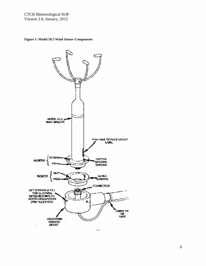
CTCR Meteorological SOP
Version 20 January 2012
6
Figure 1 Model 505 Wind Sensor Components
CTCR Meteorological SOP
Version 20 January 2012
7
A zero test requires the prevention of air movement across the sensor by covering the array A
plastic bag can be placed over the array using care not to contact the transducers or block the
sonic paths between transducers The bag should be spaced at least 2 above the transducers to
avoid sonic reflections which may affect readings The bag can be tied at the bottom with a tie
wrap or tape to prevent air movement from below the wind can deflect the bag causing air
movement inside With no air movement across the array the sensor should indicate 00 to 01
ms wind speed The wind direction output will wander to any value between 0 and 360 degrees
The sensor is designed to produce known default outputs if an object blocks the sonic signal path
between the transducers This feature is useful for verifying sensor operation and recorder
scaling For testing purposes the sonic path can be blocked by placing a finger (or any solid
object) on the face of one or more transducers
The outputs after blocking the transducers are shown in Table 6 below
Table 6 Span Test Outputs for Blocked Transducers
Wind Speed
Blocked Axis Serial Output Analog Output 0-10 V 0-25 V
North-South 100 ms 50 ms 100 V 250 V
East-West 100 ms 50 ms 100 V 250 V
Both 100 ms 50 ms 100 V 250 V
Wind Direction
Blocked Axis Serial Output Analog Output 0-10 V 0-25 V
North-South 10 degrees 10 degrees 003 V 007 V
East-West 160 degrees 160 degrees 044 V 111 V
Both 170 degrees 170 degrees 047 V 118 V
The testing of the transducers can easily be accomplished when the tower is tipped down for the
yearly inspection Table 7 lists the specifications for the wind sensor
Table 7 Model 505 Wind Sensor Specifications
Wind Speed Specifications
Range 0 to 50 msec
Accuracy plusmn 02 msec le 113 msec or plusmn 2 ge113 msec
Resolution 01 msec
Wind Direction
Range 0 to 360deg
Accuracy plusmn3deg
Resolution 1˚
CTCR Meteorological SOP
Version 20 January 2012
8
Operation
Sample Rate 5 per second
Data Output Rate 1 per second
Sonic frequency 200 KHz
Output Signals
Wind speed voltage 0-50 VDC
Wind direction voltage 0-50 VDC
RS-232 1200 to 192K Baud
Power requirement
Sensor 9-18 VDC 10 mA 12 VDC Average power
External Heater Option 15 VDC 50 Watts
Environmental
Maximum Measurement range 0 to 65 mls
Operating Temperature -40degC to +55degC no ice
Extended Temperature Range -50degC to +55degC with external heater
Physical
Weight 55 Ibs
Dimensions 1929in high 938in diameter
Model 083D Relative Humidity Temperature Sensor
The 083D-1-35 Sensor is an extremely accurate and sensitive relative humidity and temperature
sensor Response is linear with small hysteresis and negligible temperature dependence The
sensors are installed in a radiation shield before shipping The 73B radiation shield (Figure 2)
mounts on the opposite end of the boom from the 505 wind sensor on top the tower The
radiation Shields and cables have Mil Spec screw-on or twist-on cable connectors that are pre-
fitted by Met One The cable should be secured to the boom and tower with cable ties
The Relative HumidityTemperature Sensor has been calibrated at the factory and will not
change unless it is damaged Blow on the sensor for a quick check for operation the RH will
rise To check for reasonableness of operation compare the measurement with a local weather
service facility The reading will not be exactly the same but should be similar Compare the
temperature measurement to the delta Cal standard reading when conducting flow verifications
The sensor may need cleaning due to the accumulation of dust or other substances that will affect
measurements Turn off power to the sensor before attempting to clean and keep off until dry
Cleaning with distilled water will be adequate in most instances If extremely dirty or covered
with substance water will not remove isopropanol can be used Follow the instruction in the
operations manual to prevent damage to the sensor when cleaning with liquids
CTCR Meteorological SOP
Version 20 January 2012
9
Figure 2 Model 073B Radiation Shield
Table 8 Model 083D RH and Temp Sensor Specifications
Sensing Element Thin-film Capacitor
RH Range 0 - 100
Temp Range -50deg to +50degC
Response Time 15 seconds at 20degC
RH Accuracy plusmn2 RH between 10 and 100 RH
Temp Accuracy 01degC
Hysteresis For 0 to 100 to 0 excursion le 1
Temperature Coefficient plusmn004 per 1degC
Output 0 - 1 V full scale
Input Power 12V DC
Barometric Sensor 090D
The 090D (2632-1) uses an active solid-state device to sense barometric pressure with a range of
26 to 32 inches of mercury and a voltage output of 0 ndash 1 volt The sensor attaches to the tower or
other convenient location with a ldquoJrdquo bolt Orient the J box with the pressure inlet port facing
down Install the cable through the water tight fitting and connect as shown in Figure 2
CTCR Meteorological SOP
Version 20 January 2012
10
Figure 3 Installing the Barometric Sensor 090D Wiring
The sensor has been calibrated at the factory and will not change unless damaged No field
modification or calibrations can occur To check for proper operation compare to a local
weather station to see if the readings are reasonable The measurement will not be exactly the
same due to differences in elevation and measurement parameter absolute or normalized to sea
level This sensor measures absolute inches of mercury BP can also be checked when
conducting regular flow verifications or calibrations on the BAM 1020 The deltaCal standard
measures BP as millimeter (mm) or millibars (mb) and can be converted to inches mercury by
multiplying mm X 03937 and mb X 00295
Maintenance consists of inspecting the pressure inlet port for blockages and removing
obstructions if found If service or recalibration becomes necessary then send the sensor to the
manufacture
Rain Gauge 375 001 Inches This sensor measures precipitation on a continuous basis and is low-maintenance The tipping
bucket collects 001 inches of precipitation then tips and drains This triggers a switch closure
pulse that is counted The tipping bucket and rain gauge are heated to prevent accumulation of
snow and ice The sensor has been calibrated at the manufacture and should not require
adjustments after installation Mount the sensor level on a platform using the built in level and
three adjusting legs Follow the instruction in the operations manual (Appendix F) for complete
installation instructions A debris screen should be removed during the winter when snow will
accumulate
After installation manually actuate the tip bucket mechanism three times and confirm the tips
have registered on the data logger Inspect and clean the tipping buckets periodically and
physically tip to verify recording on the data logger If the sensor has been damaged or appears
to need calibration follow the instruction in the operations manual
Table 9 Model 375C Rainfall Sensor Specifications
Orifice 8 Inch Diameter
Calibration 01 Inches Rain per Switch Closure
Accuracy plusmn 1 at 1 to 3 inches per hour at 70 Fdeg
Switch Type Magnet and Reed
Mounting 3 Pad for 14 inch bolts
Dimensions 8 Inch Diameter
CTCR Meteorological SOP
Version 20 January 2012
11
Power Requirement 110 VAC
Weight 75 Pounds
Quality Control and Quality Assurance Quality Control (QC) and Quality Assurance measure are minimal due to the reliability and low
maintenance of the meteorological sensors employed The following table list all standards
used maintenance needed and actions If sensors exhibit characteristics outside of these
parameters the manufacturer will be contacted for instructions Records related to Meteorological
sensors will be tracked on the site log and summaries semiannually
Table 10 Meteorological Sensor Quality Control and Assurance Measures
Sensor Criteria Action
BX-596 ATBP Sensor
BP varies more than plusmn10 mm Hg from deltaCal Standard BAM 1020 Calibration Following SOP
Temperature varies more than plusmn2degC from deltaCal Standard BAM 1020 Calibration Following SOP
Sensor shield andor probe damaged Contact Met One for instructions
BX-592 Outside Temperature Sensor Volumetric Flow
Temperature varies more than plusmn2degC from deltaCal Standard BAM 1020 Calibration Following SOP
Temperature shield andor probe damaged Contact Met One for instructions
Model 505 Wind Sensor
Yearly zero test reading 00 to 01 ms wind speed
Contact Met One for instructions if greater than these readings
Yearly span test
Contact Met One for instructions if readings do not match those shown in Table 6
Heater not functioning Contact Met One for instructions
Relative HumidityTemperature
Sensor 083D
Yearly check for reasonableness Compare with local weather station
Yearly check for operation Blow on sensor and confirm RH rise
Barometric Sensor 090D Yearly inspection
Clean pressure inlet port for blockages when needed
Compare to deltaCal Standard Contact Met One for instructions if values do not compare reasonably
Rain Gauge 375 001 Inches
Yearly check for operation Manually tip bucket and confirm reading
Yearly check for level Use adjustment legs to level
Damage or bucket set screws loose
Follow instructions in operation manual for calibration
CTCR Meteorological SOP
Version 20 January 2012
12
Reference EPA Requirements for Quality Assurance Project Plans EPA QAR-5 Office of Environmental
Information Washington DC EPA240B-01003 March 2001
Guidance for Quality Assurance Project Plans EPA QAG5 Office of Environmental
Information Washington DC EPA240R-02009 December 2002
Guidance for Preparing Standard Operating Procedures (SOPs) EPA QAG-6 Office of
Environmental Information Washington DC EPA6000B-07001 April 2007
Met One Instruments Inc (2008) BAM 1020 particulate monitor operation manual Prepared by
Met One Instruments Inc Grants Pass OR BAM-1020-9800 Rev G
Standard Operating Procedure for the Continuous Measurement of Particulate Matter Monitoring
Sites Confederated Tribes of the Colville Reservation Air Quality Program August 2011
CTCR Meteorological SOP
Version 20 January 2012
13
Appendices
BX-596 ATBP SENSOR MANUAL
Met One Instruments Inc 1600 Washington Blvd Grants Pass Oregon 97526 Telephone 541-471-7111 Facsimile 541-541-7116
BX-S9G Sensor Manual - copy Copyright 2007 Met One Instruments Inc All Rights Reserved worldwide No part of this publication may be reproduced transmitted transcribed stored in a retrieval system or translated into any other language in any form without the express written permission of Met One Instruments Inc
Appendix A BX-596 ATBP Sensor Operation Manual
About this Manual
The BX-596 is an optional combination ambient temperature and barometric pressure sensor for use with the BAM-1020 particulate monitor The BX-596 sensor is a required accessory for all BAM-1020 configured to sample PM25 levels effective March 2007 The sensor provides ambient temperature and pressure data to the unit for actual (volumetric) flow control and flow statistics during the hourly sample cycle The BX-596 is only compatible with BAM-1020 firmware version 324 or later This manual describes the installation and operation of the BXshy596 sensor Refer to the BAM-1020 operation manual as needed
The BX-596-1 is an extended range version for extreme cold or high altitude environments
BX-59G TemperaturePressure Sensor Installed on a BAM-1020 Inlet Tube
Specifications
I
I I
I
I
I I
BX-59G Barometric Pressure Ambient Temperature Voltage Output o to 25 volts o to 25 volts
Range 525 to 825 mmHg -40 to +55 deg C Accuracy plusmn025 mmHg 25 C plusmn 15C above -30
10 Voltage 350 volts DC plusmn 02
BX-59G-1 Barometric Pressure Ambient Temperature i
Voltage Output o to 25 volts o to 25 volts Range 400 to 825 mmHg -50 to +50 deg C
Accuracy plusmn15 mmHg plusmn 15C full scale 10 Voltage 410 volts DC plusmn 02
BX-596-98DD Manua RevBdoc Page 1 of 4
Appendix A BX-596 ATBP Sensor Operation Manual
Installation and Setup
Ensure that the BAM-1020 is sited and installed properly per the instructions in the operation manual
During the installation process you will need to provide an access point for the BX-596 sensor cable to enter the shelter where the BAM-1020 is installed In some cases it is easiest to simply drill a 38 hole through the roof of the shelter about six inches away from the inlet tube then feed the cable through the hole and caulk around it to prevent leaks
There may be a better place to feed the cable into the shelter in some applications The BXshy902903 environmental shelters supplied by Met One have pre-formed access holes in the side to allow the sensor cable to be routed to the BAM-1020 Decide the best way to route the cable into the shelter The BX-596 comes with a standard 25-foot sensor cable Longer cables may be ordered if required
Remove the PM 10 head and PM25 cyclone from the top of the BAM inlet tube Attach the BXshy596 to the inlet tube (about 8 to 18 inches from the top) with the supplied U-bolt hardware Make sure that the sensor is level and tighten the U-bolt securely
Make sure the BAM-1020 is turned off then attach the sensor cable to the connector on the bottom of the BX-596 Route the loose end of the cable into the shelter and to the back of the BAM-1020 Coil up any excess length of cable Attach the cable to the back of the BAM as shown in the following table
I
BX596 ATBP Sensor Connections Wire Color Function BAM Terminal
Yellow A T Signal Output Channel 6 SIG BlackShield Ground Channel 6 COM Red +12 VDC Channel 6 POWER Green Auto 10 Signal 350V Channel 6 10 White BP Signal Output Channel 7 SIG
Reinstall the PM10 head and PM25 cyclone and seal around the cable hole with silicone if required
Operation
When the BAM-1020 is powered up with a BX-596 installed the unit will automatically sense the 10 voltage from the sensor and configure input channels six and seven to read and scale the outputs from the sensor Note The BX-596 sensor requires BAM-1020 firmware revision 320 or later The BX-596-1 extended range version requires BAM-1020 firmware revision 362 or later If the BAM firmware is not current enough then the BAM will not automatically identify and scale the sensor
Appendix A BX-596 ATBP Sensor Operation Manual
Turn ON the BAM-1020 and perform a calibration of the BX-596 Note The calibration is performed in the TESTgt FLOW screen which will not be available unless the FLOW TYPE is set to ACTUAL in the SETUPgt CALIBRATE screen You will need a reference standard measurement for ambient temperature and barometric pressure
MULTIPOINT FLOW CALIBRATION TARGET BAM STD
ltCALgt ~~~ 238 238 C BP 760 760 mmHg
FLOW 1 150 150 150 LPM FLOW 2 183 183 183 LPM FLOW 3 167 167 167 LPM
CAL NEXT DEFAULT EXIT
1 Enter the TESTgt FLOW menu as shown above The nozzle will lower automatically when this screen is entered The BAM colurnn is what the BAM-1020 measures for each parameter and the STO column is where you will enter the correct values from your reference standard The ltCALgt symbol will appear next to the parameter selected for calibration
2 Measure the ambient temperature with your reference standard positioned near the BXshy596 sensor Enter the value from your reference standard into the STO field using the arrow keys Press the CAL hot key to correct the BAM reading The BAM and STO values should now be the same
3 Press the NEXT hot key to move the ltCALgt indicator to the BP field and repeat the same steps for barometric pressure
The DEFAULT hot key can be pressed to reset the user calibration from the selected parameter and replace it with a factory setting The DEFAULT calibration should be fairly close in most cases
The BX-596 sensor is almost always calibrated as part of a BAM-1020 flow calibration Always calibrate the AT and BP channels before calibrating the flow channels as the flow rate is affected by the temperature and pressure of the ambient air
The 8X-596 temperature output may also be checked in an ice bath The ice bath test is usually never done except in some cold weather environments First calibrate the sensor at ambient temperature then use the following steps
1 Remove the stop screw from the bottom of the mounting bracket so that the electronics module is free to rotate Rotate the module counter-clockwise until it disengages from the keyhole slots and comes free from the radiation shield
2 The sensor comes with an 18 inch long ice bath extension harness This may be used to allow the temperature bead to reach the ice bath if necessary Carefully unplug the black temperature bead assembly from the top of the electronics module and install the harness between the bead and the module
3 Insert the temperature bead into the ice water bath along with your reference sensor Avoid immersing the bead assembly past the connector
Appendix A BX-596 ATBP Sensor Operation Manual
4 Allow the bead to equilibrate then compare the AT reading in the TESTgt FLOW screen to your reference sensor The readings should match within plusmn15 degrees C for the BXshy596-1 extended range sensor Note The tolerance for the regular BX-596 standard range sensor is plusmn 25 C in temperatures below -30C
5 Remove the ice bath harness and reassemble the sensor
During operation of the BAM-1020 the output from the BX-596 can be viewed from the main flow statistics screen or the OPERATE screens See the BAM-1020 manual
JI -~J
1 1~
i gt
-- --- shyv_
Ice Bath Extension Harness
Maintenance The BX-596 is designed to be low-maintenance easy to access and resistant to harsh environments There are only a few maintenance items for the sensor besides routine calibration checks
bull Remove the bottom cover and make sure that the four holes in the cover plate are clear and have not been obstructed by insects or debris These holes allow the air pressure to equilibrate inside the sensor for the barometric pressure reading Clean the inside of the electronics enclosure every 12 months or as needed
bull Clean the radiation shield assembly at least once per year Dirty shields reflect away solar radiation less efficiently
bull The circuit board is not intended to be removed or serviced by the customer bull The black temperature bead assembly may be replaced if the bead becomes damaged
The assembly simply plugs into the top of the electronics module The sensor will need to be recalibrated any time the temperature bead is replaced
Technical Support
Should you still require support after consulting your printed documentation we encourage you to contact one of our expert Technical Service representatives during normal business hours of 700 am to 400 pm Pacific Standard Time Monday through Friday In addition technical information and service bulletins are often posted on our website Please contact us and obtain a Return Authorization (RA) number before sending any equipment back to the factory This allows us to track and schedule service work and expedite customer service
Phone (541)471-7111 Fax (541)471-7116 E-Mail servicemetonecom Web wwwmetonecom
Mail Technical Services Department Met One Instruments Inc 1600 NW Washington Blvd Grants Pass OR 97526
Appendix A BX-596 ATBP Sensor Operation Manual
warranty
Products manufactured by Met One Instruments Inc are warranted against defects in material and workmanship for a period of one (1) year from the date of shipment from the factory Offered products not manufactured by Met One Instruments Inc will be warranted to the extent and in the manner warranted by the manufacturer of that product
Any product found to be defective during the warranty period will at the option of Met One Instruments Inc be replaced or repaired In no case shall the liability of Met One Instruments Inc exceed the purchase price of the product
This warranty may not apply to products that have been subject to misuse negligence accident acts of nature or that have been altered or modified other than by Met One Instruments Inc Consumable items such as bearings and batteries are not covered under this warranty
Other than the warranty set forth herein there shall be no other warranties whether expressed implied or statutory including warranties of fitness or merchantability
Service
Ary product being returiled to Met One Instruments In for service repair or calibration must be assigned a return authorization (RA) number Please call (541) 471-7111 or (972) 412-4715 for an RA number and shipping instructions
Products manufactured by Met One Instruments Inc that are returned for service repair or calibration are warranted against defects in material and workmanship for ninety(90) days from date of shipment under the same conditions as stated above
999
Appendix A BX-596 ATBP Sensor Operation Manual
Temperature Probe amp Shield Model BX-592
Operation Manual BX-592-9800
1600 Washington Blvd Regional Sales amp Service Grants Pass Oregon 97526 3206 Main St Suite 106
Met One Instruments
Telephone 541-471-7111 Facsimile 541-541-7116
Rowlett Texas 75088 Telephone 972-412-4715 Facsimile 972-412-4716
Appendix B BX-592 Temperature Probe and Shield Operation Manual
Model BX-592 Temperature Probe amp Shield Operation and Installation Manual
INTRODUCTION The Model BX-592 is a temperature probe and shield for use with the BAM-1020 particulate analyzer The BX-592 is used specifically with the BX-962 Volumetric Flow Control System used on the BAM-1020 This sensor provides temperature measurement of the outside air used to determine the temperature correction value as part of the volumetric flow calculation The sensor is designed to be connected directly to one of the analog input channels of the BAMshy1020 The BX-592 is used when there is no other source of analog temperature output from an existing temperature system at the owners location The BX-592 includes 30 ft of cable as well as a mounting adapter that attaches to the inlet tube of the BAM-1020
INSTALLATION The BX-592 is installed outside near the intake of the BAM-1020 particulate analyzer Mounting hardware is provided for direct mounting on the BAM-1020 inlet tube as shown in figure 10 Attach the temperature probe and shield to the horizontal bar using the clips on the top of the temperature shield Push the shield up onto the horizontal bar and press the grey plastic clips together until you hear the snap of the retainer locking inplace
The fitting on the mounting arm should be mounted in a convenient place near the top of the inlet tube and out of the way of the supports used to hold the inlet tube in place Tighten the set screws on the mounting adapter to hold it in place on the inlet tube The horizontal bar can be moved as necessary to mount the shield in a suitable location near the inlet tube and the PM-10 or PM-25 inlet assembly
The cable from the sensor can then be run down through the roof of the shelter or building so that it can be connected to the sensor input channel terminal block on the back of the BAMshy1020 unit
Figure 1 Temperature Sensor Installation
BX-592 Manual 31JAN2001 2
Appendix B BX-592 Temperature Probe and Shield Operation Manual
The sensor input connection should be made at sensor location six This input channel is the one used for any external temperature analog input used for the temperature correction input required by the volumetric flow controller
The BX-592 Temperature Sensor and Shield provides a special ider1tification output signal that is used by the BAM-1020 to determine what type of sensor is connected to the BAM as well as determine what the range of the temperature sensor The electrical connections to the BAMshy1020 can be see in Figure 2 Be sure that the color code of the individual wires of the cable is followed so that the sensor is not connected incorrectly to the BAM-1020 There are four wires which are connected to the four terminals of the analog inputs at the back of the BAM unit
IO~=== laquo) SIG ~2P-~~~WHTd COM ~~BLK ----~_4z ~ PWR ~2P-REO ----- I I 0 ~d)J-GRN --shyUL=== ~
SIG ~
Figure 2 Sensor Connections to BAM
Figure 2 shows the connections from the BX-592 Temperature Sensor and Shield to the BAMshy1020 Particulate Analyzer Be sure that the temperture sensor cable is connected to channel 6 of the BAM-1020 otherwise the voltage output of the sensor will not be able to be used as the temperature reference of the volumetric flow controler
For correct operation of the volumetric flow control option BX-961 the BAM-1020 must be programmed for volumetric flow operation This is done from the SETUP then CALIBRATE and then FLOW TYPE screen The default is metered flow and will need to be set for volumetric flow for tt1ts option to work correctly See the BAM-1020 Manual section 414 for information on the Calibrate Screen and in section 63 for information on the field calibration of the flow system
SPECIFICATIONS The following are the specifications of the BX-592 Temperature Sensor and Shield These are subject to change as determined by Met One Instruments Inc The shield of the BX-592 provides protection of the temperature probe from errors that are caused by direct solar radiation The shape allows for the wind to naturally aspirate the shield to reduce the total effect of solar radiation on the temperature measurement
Temperature Probe Type Thermistor Bead multi-element
Temperature Accuracy
Temperature Range
Sensor Output o to 1 VDC for temperature range
Time Constant 10 Seconds in still air
BX-592 Manua13IJAN2001 3
Appendix B BX-592 Temperature Probe and Shield Operation Manual
The shield is mounted from the top of the shield using two snap clamps designed for a 1 diameter tube or a IPS Pipe The mounting adapter and a short boom are provided for attachment to the inlet tube of the BAM-1020
MAINTENANCE amp CALIBRATION The temperature probe and shield require no specific maintenance other than normal cleaning of dirt and dust to prevent the degredataion of the reflectiveness of the shield If there is any build up of materials inside the shield they should be cleaned out so that there is a free path for air flow around the temperature probe
On a regular basis the output of the temperature probe displayed on the screen of the BAMshy1020 should be checked against a reference thermometer to be sure that the BX-592 is providing accurate information for the calculation of volumetric flow There are no adjustments inside the temperature probe and any repairs should be handled by the factory
Before returning a faulty probe the factory should be contacted a RA (Return Authorization) should be obtained and the problem noted on the RA This will insure that the repairs are made quickly and returned for installation
TROUBLE SHOOTING
Symptom Identify Problem Solution Incorrect Temperature indicated on BAM Display
Verify that connections to the rear panel of the BAM are correct and to channel 6
Change wiring to follow diagram as indicated in figure 2 of this manual
From setup menu channel Change settings from parameters screen verify that MANUAL Mode to Auto ID channel 6 is set for Auto ID mode for probe to work and not in MANUAL Mode correctly Examine output of BX-592 to Using a volt meter measure verify that it has the correct voltage between the black and voltage output for the current white wires 0-1 volt is ambinet temperature equivalent to -30 to 50
degrees C Le 21degC =637 volts If this is not correct return probe for repair
Volumetric Flow Control is not operating
Go to the Setup then Calibrate screen menu and verify that the flow type is set to volumetric and not metered
Default setting is for metered it will be necessary to change setting to volumetric flow type
Examine rear of BAM-1020 and see if there is a flow adjusment knob on the back of the unit right above the vacuum line
If there is a knob here it is most likely that volumetric flow control is not installed on this unit Contact Met One Instruments for advice
Volumetric flow value does not match audit flow meter connected to BAM
From setup menu select flow and examine the current measured flow value of the BAM
Recalibrate the BAM flow meter using the proceedure in the manual section 63 Field Calibration of Flow System
Verify that the audit instrument being used has been calibrated for volumetric flow monitoring
Adjust flow audit device for correct measurement of volumetric flow
BX-592 Manual 3IJAN200 1 4
Appendix B BX-592 Temperature Probe and Shield Operation Manual
For any other specific problems with the BX-592 or the Volumetric Flow Option BX-961 contact the factory
Met One Instruments Inc 1600 NW Washington Blvd Grants Pass Oregon 97527
(541) 471-7111 Voice (541 ) 471-7116 FAX
service metonecom e-mail
Visit our web page at httpwwwmetonecom
BX-592 Manual 31JAN2001 5
Appendix B BX-592 Temperature Probe and Shield Operation Manual
MODEL 505 WIND SENSOR
OPERATION MANUAL Document No 505-9800
1600 Washington Blvd Grants Pass Oregon 97526
Met One Telephone 541-471-7111 Instruments Facsimile 541-541-7116
Regional Sales amp Service 3206 Main St Suite 106 Rowlett Texas 75088 Telephone 9724124715 Facsimile 972-412-4716
505-9800 Rev Edoc
Appendix C Model 505 Wind Sensor Operation Manual
Copyright Notice
505 Sonic Wind Sensor Manual
copy Copyright 2005 Met One Instruments Inc AI Rights Reserved Worldwide No part of this publication may be reproduced transmitted transcribed stored in a retrieval system or translated into any other language in any form by any means without the express written permission of Met One Instruments Inc
Technical Support Should you require support please consult your printed documentation to resolve your problem If you are still experiencing difficulty you may contact a Technical Service representative during normal business hours-730 am to 400 pm Pacific Standard Time Monday through Friday
Voice (541) 471-7111
Fax (541) 471-7116
E-Mail servicemetonecom
Mail Technical Services Department Met One Instruments Inc 1600 Washington Boulevard Grants Pass OR 97526
505-9800 Rev E Page 2
Appendix C Model 505 Wind Sensor Operation Manual
TABLE OF CONTENTS 1 GENEAAL INFORIIATION 5
2 INSTALLATION 5
21 LTNPACKlNG 5 22 PREPARATION 5 23 SENSOR SITING 6
Figure 2-1 Siting Wind Instroments 6 24 ORIENTATION WITH FIXTURE 7
Figure 2-2 Orientation Fixture 7 25 ORIENTATION WITHOUT FIXTURE (SEE FIGURE 2-3 AND 2-4) 8 26 EXTERNAL HEATER 8
Figure 2-3 505 Wind Sensor Components 9 Figure 2-4 Alignment aSensor to Troe North 10
27 INSTALLATION OF AVERY DETERRENTS 11 Figure 2-5 InstallatIOn ofAviary Delerrents I
28 CONNECTIONS TO RECORDING ELECfRONICS 12
Figure 2-7 Factory Standard Analog amp Rf-232 Output Connections (Cable 9574 wi Differential Amplifier
Figure 2-8 Factory Custom SDI-12 Output Connections 3
Figure 2-6 Amplifier (9573) attached to Cable (9574) and wiring in box 12
9573) 12
Figure 2-9 Factory Custom RS4221485 Output Connections 13 28 SIGNAL OUTPUTS ANALOG RS-232 ANDSDI-12 13 29 SIGNAL OUTPUTS - RS422 AND RS485 14
3 OPERATIONAL CHECK-OUT AND CALmRATION 14
31 GENERM 14 32 RECORDING ELECTRONICS 14 33 ZERO TEST 14 34 SPAN TEST 14
4 MAINTENANCE AND TROlTBLESHOOTING 15
41 GENERAL MAlNTENANCE SCHEDULE 15 42 TROlTBfJESHOOTING 15
5 TIIEORY OF OPEAATION 16
51 SPEED OF SOUND IN AlR 16 52 SPEED OF S()UND PRINCIPLE 16 53 CALCULATION OF THE WIND VELOCITy 16
6 SPECIFICATIONS 17
FIGURE 6- 505 Wind Sensor Outline Dimensions 18
APPENDIX A - WIND DIRECTION SENSOR ORIENTATION 19
APPENDIX B - WIND SENSOR MOUNTING OPTIONS 22
APPENDIX C - HEATER CONFIGURATION AND WIRING 23
APPENDIX D - RS2J2 COMMAND SET 25
GENERAL PROTOCOL 25
1 RS-2J2 DATA OUTPUT PROTOCOL 25
11 ERROR CODE 26
2 USER COMMAND SET _ 27
21 L8-VERBOSE CONTROL OF RS-232 PARAMETER LABELS 27
505-9800 Rev E Page 3
Appendix C Model 505 Wind Sensor Operation Manual
22 MS-MAxLMUM FULL SCALE WIND SPEED 27 23 SU-WINO SPEED UNITS 27 24 QU-QUlT 27 25 SB-SERIAL BAUD RATE 28 26 ST-SERIAL TRIGGER (RS-485 ONLy) 28 27 IT-SONIC TEMPERATURE 28 28 VN-VERSION NUMBER 28 29 VS-FULL SCALE ANALOG OUTPUT VOLTAGE FOR WINO SPEED Ai~O WINO DIRECTION 28
505-9800 Rev E Page 4
Appendix C Model 505 Wind Sensor Operation Manual
MODEL 505 WIND SENSOR OPERATION MANUAL
1 GENERAL INFORMATION
The Met One Instruments Model 505 Wind Sensor is a solid-state ultrasonic instrument capable of measuring wind speed and wind direction in the U and V axes Sonic pulses are generated at the transducers and are received by opposing transducers Mathematics derived for these sonic pulses provide a wind velocity measurement in each of the corresponding axes
The 505 uses a microprocessor-based digital electronic measurement system to control the sample rate and compute the wind speed and wind direction The sensor is factory calibrated and requires no field calibration In the field the operation of the sensor can be quickly checked using a combination of simple tests A zero chamber or bag is used to verify the zero reference by covering the entire sensor or individual outputs are checked by blocking various combinations of sensors
The 505 provides are variety of outputs to suit the connection requirements of the user Standard outputs are voltage and RS-232 SDI-12 and RS422485 outputs are configured at the factory
2 INSTALLATION
21 UNPACKING
Carefully remove the sensor from its shipping container and inspect it for damage Referring to the packing list check for shortages Any claims for damages should be filed promptly with the carrier
The sensor is a precision electromechanical transducer Always handle it with care exercising particular caution to ensure that the instrument is not subjected to side loading shock or other abuse After initial inspection keep the sensor in its shipping container for protection until actual installation
22 PREPARATION
For accurate measurements the sensor mount must be rigid with little or no movement from the wind The sensor is designed for installation in a Model 3188 mounting and alignment fixture This provides a mount for use on a horizontal IPS pipe (105- 00) boom Mounting information and diagrams can be found in Appendix B of this manual
The 3188 Sensor Mounting Fixture includes a keyed bushing which will be adjusted for alignment to North orientation This enables the sensor to be removed and replaced without requiring realignment Three captive machine screws are used to secure the sensor to the keyed bushing
If a temperature shield such as the Model 0738 is to be used in the configuration the Model 1539-4 Arm and 1552 Mount is recommended These parts provide the necessary mounting for a vertical mast of 0 IPS pipe (105 OD) This same configuration can also be used to mount other sensors as well as providing a way to mount the sensor on a vertical mast (See Appendix B for Mounting Details)
505-9800 Rev E Page 5
Appendix C Model 505 Wind Sensor Operation Manual
23 SENSOR SITING
The primary objective of instrument siting is to place the instrument in a location where it can make precise measurements that are representative of the general state of the atmosphere in that area Because most atmospheric properties change dramatically with height and surroundings certain somewhat arbitrary conventions must be observed so that measurements can be compared
lOT
Figure 2-1 Siting Wind Instruments
The standard exposure of wind instruments over level open terrain is 10 meters above the ground (WMO 1971) however optimum measurement height may vary according to data needs Open terrain is defined as an area where the horizontal distance between the wind sensor and any obstruction is at least ten (10) times the height of that obstruction An obstruction may be man-made (such as a building) or natural (such as a tree) (See Figure 2-1)
The wind instrument should be securely mounted on a mast that will not twist rotate or sway If it is necessary to mount the wind instrument on the roof of a building it should be mounted high enough to be out of the area in which the airflow is disturbed by the building This is usually 15 times the height of the building above the roof so that it is out of the wake of the obstruction This is not a good practice however and should only be resorted to when absolutely necessary
Wind instruments are best sited when they are used on towers The tower should be located in an open level area representative of the area under study Towers should be of the open grid type of construction such as is typical of most television and radio broadcast towers Enclosed towers stacks water storage tanks grain elevators cooling towers and similar structures should not be used
Wind instruments should be mounted above the top of the tower on booms projecting horizontally out from the tower If a boom is used it should support the sensor at a distance equal to minimum of twice or at best three times the maximum diameter or diagonal of the tower away from the nearest point on the tower On large towers with large verticals it may be best to place the sensor at least 5 tower leg diameters from the tower leg The boom should project into the direction which provides the least distortion for the most important wind direction For example a boom mounted to the east of the tower will provide least distortion for north or south winds
505-9800 Rev E PageS
Appendix C Model 505 Wind Sensor Operation Manual
Weather sensors are sensitive to direct or nearby lightning strikes A well-grounded metal rod or frame should be placed above the sensor installation In addition the shield on the signal cable leading to the translator must be connected to a good earth ground at the translator end and the cable route should not be vulnerable to lightning
24 ORIENTATION WITH FIXTURE
The Orientation Fixture Model 705 is used for very accurate positioning of the 505 sensor with respect to a benchmark or other object that can be visually obselVed If a compass is used to establish a benchmark the reading should be taken away from heavy metal objects which can affect the reading and should be corrected for declination of the magnetic north pole The benchmark is set to true north of the sensor site Information on determining true North can be found in Appendix A of this manual
The fixture contains a telescopic sight with crosshairs and includes a keyed base identical to that on the sensor The fixture is specifically designed for use with the 3188 Sensor Mounting Fixture The base of the fixture is keyed so that the object lens of the sight assumes the same position as the north side of the sensor
Before orienting the sensor ensure that it is vertical and adjust the cross arm as necessary Orientation of the sensor is then performed with the fixture installed on the cross arm in place of the sensor (The three screws in the base of the fixture must be tightened to ensure proper orientation in the cross arm) Loosening the three setscrews on the side of the sensor mount allows free rotation of the keyed bushing and orientation fixture The ring and fixture are then rotated to position the benchmark in the center of the sight crosshairs The sight can be tilted as necessary by loosening the slotted screw on the side of the fixture The set screws are then tightened the fixture removed and the sensor installed in its place The sensor is now oriented for zero (north) wind direction signal output when the wind is from north
OSIECTlENS
Figure 2 2 Orientation Fixture
The electrical connector on the bottom of the sensor should be properly mated to the cable connector and the three captive screws on the base of the sensor should be tightened
When using the orientation fixture assure that the two-piece mounting assembly is properly aligned The upper half of the assembly contains a horizontal peg which must seat in the vshynotch located in the lower half The knurled knob on the lower half is used to secure the two sections and should be tight
505-9800 Rev E Page 7
Appendix C Model 505 Wind Sensor Operation Manual
25 ORIENTATION WITHOUT FIXTURE (See FIGURE 2-3 and 2-4)
Establish a True North benchmark See Appendix A for aids to determine True North This should be a point directly north from the sensors mounted location This point should allow easy access so that a person may sight the sensor with a spotting telescope If a compass is used to establish a benchmark the reading should be taken away from heavy metal objects which can affect the reading and should be corrected for declination of the magnetic north pole The benchmark is set due north of the sensor site
One person is located at True North benchmark equipped with a spotting scope A second person is located at the sensor The sensor alignment may be established as follows
A Install the sensor into the alignment bushing and secure with the two setscrews under the 3188 Alignment Fixture Keep the three setscrews around the ring of the fixture loose so that the ring can be rotated into position
B Turn the sensor so that the sensor paints to the North benchmark Tighten the 3 setscrews and recheck align ment
C Connect the 9574-cable assembly to the sensor Secure cable to boom with cable ties or tape to prevent damage
D The sensor can be removed without requiring realignment at any time Simply remove the sensor The alignment bushing remains proper1y oriented in the fitting
26 EXTERNAL HEATER
The Optional External Heater provides de-icing for the sensor arms and prevents the accumulation of ice which might block the sonic sensor elements The heater consists of a laminated heater material that is custom designed and wrapped around the four sensor arms and sonic sensor element housings The heater controller requires 15 to 24 VACNDC at approximately 4-5 amps at startup There are jumper connections on the controller board for the selection of power source The controller is normally provided with the jumpers not installed This is for 24 volts AC operation of the heaters Heater power can be supplied from a power transformer or a Met One Instruments supplied power unit in a weatherproof box The proportional controlled heater uses maximum current at start-up and power requirement goes down as the sensorheater reaches stability The heater is activated at 38 degrees F and will keep the arms ice-free at temperatures down to below -20 degrees F The connection information can be found in Appendix C of this manual
The temperature controller electronics box should be mounted no more than 5 feet from the sensor using the cable supplied with the heater controller The power cable should be of minimum 16 AWG wire and cable length should be at a minimum to prevent power loss due to cable resistance at the 4-amp power requirement
505-9800 Rev E Page 8
Appendix C Model 505 Wind Sensor Operation Manual
MODEL 505 WINO SENSOR
NORTH SCREWPIN ____~~--
THIS SIDE TO FACE SOlTTH LABEL
NORTH SLOT HOLE~middot-c-lIIo-
SET SCREWS (3 EA FOR SECURING
KEYED BUSHING TO HORTH ORIENTATION
(7164- ALLEN KEY)
Figure 2-3 505 Wind Sensor Components
Page 9 505-9800 Rev E
Appendix C Model 505 Wind Sensor Operation Manual
SOUTHSIDE SENSOR TRANSDUCER SHOULD BE SEEN EaUALLY DIVIDED
BY NORTHSIDE (NEAR) ARM
Figure 2-4 Alignment of Sensor to True North
505-9800 Rev E Page 10
Appendix C Model 505 Wind Sensor Operation Manual
27 INSTALLATION OF AVERY DETERRENTS
To prevent birds from entering the pathway between the sensors a vertical stainless steel rod is located in the center of the sensor array_ To keep birds from perching on the sensors stainless steel wire aviary deterrent need to be installed on the sensor prior to installation in the fixture
NOTE The stainless steel wires used for the aviary deterrents are very sharp The wire is spring steel and there s the possibility that it could slip off during the installation Use care
when installing the aviary deterrent and be careful after installation
PROTECTIVE GLASSES SHOULD BE WORN DURING INSTALLATION
Installed A viarv Deterrents
area
AVIARY DETERRENTS bull PIIIih ends IowaIds eoch ltlttler lil qgten up
spring d1amccr bull Slide owr lranllducer 10 mounIing llIII bull ~6l as requRd 60 that avlary
delemK1N are pointed ~
MOUNTING AREA
Figure 2-5 Installation of Aviary Deterrents
WARNING If the aviary deterrents are not properly installed The sensor may experience signal degradation Install as shown DO NOT allow for the spring section of the aviary deterrent to contact the transducer portion of the sensor array_
505-9800 Rev E Page 11
Appendix C Model 505 Wind Sensor Operation Manual
28 CONNECTIONS TO RECORDING ELECTRONICS
Route the cable to the data-recording device Secure the cable with cable ties or tape The 9574shycable assembly contains 7 wires and a shield Typical wiring hookup is shown in the figures below Actual wiring will depend upon the version of the sensor To determine which of the three connections drawings apply examine the cable part number at both ends of the cable
Cable type 9574 includes the 9573 Differential Amptifier it is located at the end of the cable opposite the sensor connector The amplifier provides high immunity to any noise that might be picked up the sensor cables It is recommended that this cable with amplifier be used whenever connected to a single ended input recorder If necessary to remove the differential amplifier a wiring diagram has been included in the top of the small amplifier enclosure A small screwdriver is provided for use on the small terminal screws on the PC Board of the 9573 Amplifier Be sure that the connection color codes are followed so that no wiring error occurs See below
Warning If you are connecting this 505 to an older 3155-cable assembly and are using the black wire as signal common disconnect it because it will short out the RS-232 transmitter No damage will occur to the circuit but the 505 current consumption will increase by 20 rnA
TO SONIC
~ n 0 SHLD (WTIBN) +12Y(Wiri) 0 0 NIC wo oOt-(RpoundD 0 0 GND(GRN) WD 0lIT~ (OAN) 0 0 ncD(8LK) W8 ~+(BLU) 0 0 RXC(IRN) NC 0 0 WSIN+(BW) RXD(8fCN) 0 0 NIC TXDl8LJC) 0 0 WDW+(RED) OND(GRN) 0 0 WDIN-(ORN) NIC Omiddot 0 +12V(WtfT) SHLD (WTIBN) 0 J1 r-
TO DATALOGGIR
Figure 2-6 Amplifier (9573) attached to Cable (9674) and wiring in box
Sensor Common
Power Common WHITE
RED
+12V Power
BROWN RXRS-232 BLACK TXRS-232
Wind Direction Voltage BLUE OR YELLOW Wind Speed Voltag~
Shield WHITEBROWN
Figure 2-7 Factory Standard Analog amp RS-232 Output Connections (Cable 9574 wI Differential Amplifier 9573)
505-9800 Rev E Page 12
Appendix C Model 505 Wind Sensor Operation Manual
o NG[ GREEN WHITE
BROWN
aLACK
REO
BLUE OR YEllOW
Sensor Common
Power Common
+12VPower
Not Used
Not Used
Not Used SOI-12 Output
Shield WHITEBROWN
Figure 2middot8 Factory Custom SDI~12 Output Connections
ORANGE
RED
Sensor Common GREEN Power Common WHITE +12V Power
BROWN RX f
BLACK RX shy
TX+ BLUE OR YELLOW TX-
Shield WHITEBROWN
Figure 2-9 Factory Custom RS4221485 Output Connections
28 SIGNAL OUTPUTS - AnalogJ RS-232 and 501-12
The standard configuration of the sensor provides for a voltage outputs for wind speed and direction as well as RS-232 Data The default output voltage is 10 volts full scale for 50 meterssecond and 360 degrees of direction Alternate full-scale values can be changed by using the RS-232 command set discussed in Appendix O The R8-232 output occurs every second in the format S sssS 0 ddd ltcrgtltIfgt where ssss is the wind speed value up to 9999 and the direction ddd up to a value of 360 RS-232 output is at 9600 baud 8 data bits 1 stop bit and no parity
As an option an output of 801-12 Data from the sensor is available In this configuration it is the only available output and is in the format +ssss+ddd ltcrgtltlfgt The same values for sssS and ddd as the RS-232 format are output The 801-12 handshake is per the 801-12 specifications and format In this configuration the RS-232 output or analog output is no longer available from the sensor
505-9800 Rev E Page 13
Appendix C Model 505 Wind Sensor Operation Manual
29 SIGNAL OUTPUTS - RS422 and RS485
In this configuration the sensor has no analog outputs (see diagram Factory Custom RS422RS485 Output Connections The correct sensor cable for this configuration is part number 3379
The default serial trigger (sensor address) is 1 After receiving 1 the sensor will return wind speed and wind direction in the same format as with RS232 (S sSSs D ddd ltcrgtltlfraquo
To use the RS232 Command Set defined in Appendix 0 the sensor must first be put into Terminal Mode by sending (three exclamation points) The serial trigger is not used in this case and there must be only one sensor connected on the serial buss The sensor will return when in Terminal Mode and will then accept RS232 commands The au (quit) command will take the sensor out of Terminal Mode and return it to normal operating mode
3 OPERATIONAL CHECK-OUT AND CALIBRATION
31 GENERAL
Operation of the 50S is essentially automatic and no specific sensor calibration is required for normal operation The sensor has been calibrated in a wind tunnel at the factory prior to shipment
32 RECORDING ELECTRONICS
The sensor may be connected to a variety of data recorders and translators Standard wind speed range is O-SO mls and wind direction range is 0-360 degrees Standard output voltage is 0-10V with 0-2SV and O-SOV as available options Refer to the calibration certificate supplied with the sensor to determine the actual output
To ensure that the recorder is scaled properly it is recommended that zero and span tests are performed after the sensor is connected and operational
33 ZERO TEST
A zero test requires no air movement across the sensor array so a means of covering the array is needed A plastic bag can be placed over the array using care not to contact the transducers or block the sonic paths between transducers The bag should be spaced at least 2 above the transducers to avoid sonic reflections which may affect readings The bag can be tied at the bottom with a tie wrap or tape to prevent air movement from below Keep in mind that wind can defrect the bag causing air movement inside
The preferred method is to use a box insulated with foam to prevent reflections and spaced so that the top is at Jeast 2 above the transducers Again the bottom should be sealed around the sensor to isolate the array from ambient air movement
With no air movement across the array the sensor should indicate 00 to 01 ms wind speed The wind direction output will wander to any value between 0 and 360 degrees
34 SPAN TEST
The sensor is designed to produce known default outputs if an object blocks the sonic signal path between the transducers This feature is useful for verifying sensor operation and recorder scaling For testing purposes the sonic path can be blocked by placing a finger (or any solid object) on the face of one or more transducers
505-9800 Rev E Page 14
Appendix C Model 505 Wind Sensor Operation Manual
NOTE The following table defines the sensor outputs with blocked paths
Wind Speed Blocked Axis Serial Output North-South 100 mls East-West 100 mls 80th 100 mls
Analog Out~ut 50 mls 50 mls 50 mls
D-10V 100V 100V 100V
0-2SV 250V 250V 2S0V
O-SOV 500V SOOV SOOV
Wind Direction Blocked Axis Serial Output Analog Output D-10V 0-25V D-50V North-South 10 Deg 10 Deg 003V 007V 014V East-West 160 Deg 160 Deg O44V 111V 222V Both 170 Deg 1700eg 047V 118V 236V
4 MAINTENANCE AND TROUBLESHOOTING
The 50S sensor is sealed and there are no replaceable parts contained therein The sensor does not require periodic calibration and there are no internal adjustments that can be made
41 GENERAL MAINTENANCE SCHEDULE
12-24 month intervals
The Model 505 Wind Sensor should be inspected periodically for physical damage to the sensor array assembly cable and cable connections Inspect all transducers to be sure they are securely fastened
Schedule based on average to adverse conditions
42 TROUBLESHOOTING ------ --shy--=-----------------==-----~~---- ----~-~-~~~~~~---~-----~ ----~~~~~~~--
~________~piom _~ __ ____ _____ ~~o~babl~9_C1l1~~_~___ ~__+_-_-A-ct-io-n-to-R-eL-pa_ir__---i
Wind Speed output goes to full Blocked pathway 1 - Check path and clear scale
Failed sensor 2 - If clear contact factory for Return Authorization to repair sensor
Wind Speed output high but not Common mode voltage 1 - Replace cable with part full scale number 9574 (with 9573
differential-to- single-ended converter)
supply 2 - Use 3379 cable and power sensor with isolated power separate from recorder power supply
inputs 3 - Use 3379 cable and connect sensor signals to differential on recorder
505-9800 Rev E Page 15
Appendix C Model 505 Wind Sensor Operation Manual
5 THEORY OF OPERATION
51 SPEED OF SOUND IN AIR
The speed of sound in still air can be measured accurately between two points a few centimeters apart by two ultrasonic transducers set at that distance The resulting speed of sound is a known function of the air temperature and composition
The speed of sound waves in an ideal gas may be written
where R is the universal gas constant (083134 mJmol K) T is the temperature in Kelvin M is the molecular weight (gramsmol) of the gas and L is the ratio of heat capacities Cp and Gy Cp
and Cyare the specific heats at constant pressure and constant volume of the gas respectively
52 SPEED OF SOUND PRINCIPLE
The transit time of a sound signal traveling from one end of a sound path to the other separated by distance d can be written as follows (Schotand 1955)
where V is the total velocity Vdand Vnare velocity components in the directions parallel and normal to the sound path and C is the velocity of sound in still air If two transit times t1 and t2 in opposite directions on the same path are directed Vd can be obtained independent from V and Vn as follows
It is this principle that is used to compute the velocity of the air in the path between two opposing transducers
53 CALCULATION OF THE WIND VELOCITY
In still air t1 and t2 are equal For a distance 15 cm at 20deg C the transit time is approximately 450 IJs If a 20 mls wind is in the direction of the sonic pulse the transit time t1 will be approximately 427 IJs If the wind is opposing the sonic pulse the transit time will be approximately 482 IJs If these two values are used in the previous equation the resultant velocity from equation will be 20 ms
505-9800 Rev E Page 16
Appendix C Model 505 Wind Sensor Operation Manual
6 SPECIFICATIONS
Sonic Wind Sensor Model 606
Wind Speed Range Accuracy Resolution
Wind Direction Range Accuracy Resolution
Operation Sample Rate Data Output Rate Sonic frequency
Output Signals Wind speed voltage Wind direction voltage RS-232
Optional Digita) Outputs
Power requirement Sensor
External Heater Option
Environmental Maximum Measurement range Operating Temperature Extended Temperature Range
Physical Weight Dimensions
Options Signal Cable Horizontal Mount amp Orientation Fixture External Heater with Control Box External Heater Power Source Programming Cable amp Power Supply
oto 50 msec plusmn 02 rnIsec 113 msec or plusmn 2 gt- 113 msec 01 msec
5 per second 1 per second 200 KHz
0- 50 VDC (Specified at time of purchase) 0- 50 VDC (Specified at time of purchase) 1200 to 192K Baud
501-12 RS-422 or RS-485 (Specified at time of purchase)
9-18 VDC 10 mA 12 VDC Average power requires 75 amp pulse for 2msec
15 VDC 50 Watts
oto 65 mls -40degC to +55degC no ice -SOdegC to +55degC with external heater
S5 Ibs (25 Kg) 1929in (490mm) high 938in (238mm) diameter
PN 9S74 - Specify length PN 3188 SO5H 50SPS (100 to 240 VAC SO60 HZ) 1SVDC 4 amps TBD
Heater Options must be specified at time of purchase middotSpecifications Subject to Change without prior Notice
50S-9800 Rev E Page 17
Appendix C Model 505 Wind Sensor Operation Manual
LLJ-oIIIo----IOODfA
--20001t
FIGURE 6-1 505 Wind Sensor Outline Dimensions
505-9800 Rev E Page 18
Appendix C Model 505 Wind Sensor Operation Manual
APPENDIX A - WIND DIRECTION SENSOR ORIENTATION
INTRODUCTION Determining True North or Magnetic Declination is very important to the proper setup and orientation of the wind direction portion of the sonic wind sensor The declination value is used to determine the difference between True North and magnetic North This value varies around the world depending upon your location The following procedure can be used to either point the sonic wind sensor to True North
ADJUSTMENT Orientation of the wind direction sensor is done after the location of True North has been determined True North is usually found by reading a magnetic compass and applying the correction for magnetic declination where magnetic declination is the number of degrees between True North and Magnetic North Magnetic declination for a specific site can be obtained from a USGS topographic map pilots maps local airport or through a computer service offered by the USGS called GEOMAG
The following map showing magnetic declination for the contiguous United States is shown in the figure 1 can be used for determination of declination Tilis will depend upon the accuracy requirement required Alternately use a more accurate method of detemlining declination from magnetic North
Subtract declination from 3600 Add declination to 0deg 20W
Figure 1 typical declination values in the USA
Declination angles east of True North are considered negative and are subtracted from 0 or (360) degrees to get True North as shown in figure 2 Declination angles west of True North are considered positive and are added to 0 degrees to get True North as shown in figure 3 For example the declination for Grants Pass Oregon is 17deg East True North is 3600 -17deg or 3430 as read on a compass
505-9800 Rev E Page 19
Appendix C Model 505 Wind Sensor Operation Manual
Alignment to North Orientation is most easily done with two people one to aim and adjust the sensor while the other observes the wind direction display (Once True North is located the South reference can be determined)
1 Establish a reference point on the horizon for True North Sighting down the instrument centerline aim the two arms of the NorthSouth pair at True North with the locking set screw pointed South
2 Align the sensor adapter or adapter mount Loosen the setscrews that secure the base of the sensor to the cross arm While viewing the positionrotation of the Nortl1South sensor arms slowly rotate the sensor base until the two arms point to True North that was determined by earlier measurement using compass
Other methods employ observations using the North Star or the sun and are discussed in the Quality Assurance Handbook for Air Pollution Measurement Systems Volume IV Meteorological Measurements
Determining Local Magnetic Declination Several resources for determining the magnetic declination of any site in the world can be found on the internet or can be accessed by modem using any common terminal program
GEOMAG is a resource that can be accessed by telephone or the Internet (Telnet) connection GEOMAG is accessed by calling 1-800-358-2663 with a computer and telephone modem and communications program such as HyperTerminal GEOMAG can also be accessed by the internet using the address telnetllneiscrusgsgov
GEOMAG prompts the caller for site latitude longitude and elevation which it uses to determine the magnetic declination and annual change The follOWing Menu and prompts are from GEOMAG Use the username QED
MAIN MENU NeecJe POInfS toType Q for Quick Epicenter Determinations (QED) Magnetic North
L for Earthquake Lists (EaUST) M for Geomagnetic Field Values (GEOMAG) X to log out
Enter program option M
Would you like information on how to run GEOMAG (YN) N
FIGURE 2 Declination Angles East ofOptions True North Are Subtracted from 0 to Get True North 1 = Field Values(D I HXZ F)
2 =Magnetic Pole Positions 3 Dipole Axis and Magnitude 4 Magnetic Center
Display values twice [N] press return Name of field model [USCON951 press return Date [Current date] press return Latitude 4225 N Longitude 12320 W Elevation 1000 Units (mkmft) ft
FIGURE 3 Declinatiof1 Angles West of True North Are Added to 0 to Get True North
505-9800 Rev E Page 20
Appendix C Model 505 Wind Sensor Operation Manual
Example of report generated by GEOMAG Model USCON95 Latitude 4225 N Date 211399 Longitude 123120 W Elevation 1000000 ft
D I H X Y Z F deg min deg min nT nT nT nT nT
17 175 65 73 22056 21059 6555 47560 52425 Annual change 0 -24 0 -17 -29 18 -156 -662 -613
The calculated dedi nation would be 17 degrees and 175 minutes for Grants Pass Oregon The declination in the example above is listed as 17 degrees and 175 minutes Expressed in degrees this would be 173 degrees As shown in Figure 1 the declination for Oregon is east so True North for this site is 360 - 173 or 3427 degrees The annual change is -24 minutes In this case a value 343 degrees would probably be sufficient for most measurement accuracy
An alternative method is to find a USGS map and examine the text at the bottom center of the map At this point either a written indication is given or a symbol similar to the one seen below will be found This would indicate a declination of 15 degrees West-showing MN (magnetic North) to True North (Star) Other sources such as the local airport can be helpful in determining the correct declination
1D23 25 MilS
UTM GR-O AND 1971 MAGNETIC NORTH OECLINATION AT CENTER OF SHEET
505-9800 Rev E Page 21
Appendix C Model 505 Wind Sensor Operation Manual
r=======~ -C_ARM-c-r--r-___-r
193 MOUNTING BOOM
APPENDIX B - WIND SENSOR MOUNTING OPTIONS
TYPICAL VERTICAL MOUNTING WITH 191-6 CROSS ARM
3168 AtlGINT FlXTmE
TOP OF TOWER
TYPICAL HORIZONTAL MOUNnNG
3188 AlIGN1NT FIXTLRE
-34 IfICH PS PIPE OR II~CH DlA flO(J1
505-9800 Rev E Page 22
Appendix C Model 505 Wind Sensor Operation Manual
APPENDIX C - HEATER CONFIGURATION AND WIRING
5VJ H HEAT R HH~ING lJc_ r1
5fl5 WllO SENSOR WITH HEA TER ARRAY
3379 SIGNAL CADLE
I ALIGNMENT OASE MClJEL 3100 TEt-PERATURE
CONTROLLER
reg
505PS POWER SUPPL Y lJNIT NORMAL POWER INPUT
Fm HEATER bull bullVCLTS AC OR
TO SEIfJC)R j
HEATER UNIT
~ ro 2rJ0 VAC POWER
505-9800 Rev E Page 23
Appendix C Model 505 Wind Sensor Operation Manual
00
01 o yco o o 0 OPTIONAL ~ 505 PS SONIC WIND SENSOR m HEATER POWER SUPPLY
MOUNTl NG ON VERTICAL r PE~ 2-114 DIAMETEr-deg
---1__(I I rlif 1~I
AC POWER CORD S LONG
1201240 VAC POWER AT 14 AMPS INPUT OUTPUT 15 VDC AT 4 AMPS
U w
CO (J)
~
WEATHERPROOF ENCL
~ SONIC SENSOR - 5FT LONG ~
CUT AS NECESSARY 25 FT LONG auPPUED
2 CONDUCTOR 16 AWG CABLE BETWEEN POWER SUPPLY amp CONTROL BOX
HEATER CONTROL UNIT PART 3254 FOR SONIC WIND SENSORS
(SUPPLIED WITH HEATED SENSOR)
U08oa T FOR MOUNllNG ON VERLPIPE 314 TO z14 DIAMETER
---3871 [E-23Jrl J i II
CI In I In
WEATHERPROOF INCshy
POW UNSOR CABUi TO J
FOR USE WITH SONIC WIND SENSORS SOSHAND 03SAoH
I
Appendix C Model 505 Wind Sensor Operation Manual
APPENDIX D - RS232 Command Set
General Protocol
The computer interface commands use a simple ASCII packet protocol Only one command is transferred per packet
To enter the command mode send the exclamation point () character until the unit returns If
The unit will remain in the command mode until the quit command (QU) is received or a power reset
Command packets are constructed with a two (2) character command and if required a data string
All commands must end with a carriage return (OxOD)
The unit will echo back the command string terminated with a carriage return and line feed (OxOA)
Data string requirements are described with each command
A command with no argument returns the current setting
The default R5-232 configuration is 96008 N 1
There are two command sets-User and Factory
1 RS232 Data Output Protocol
The typical RS-232 data output stream has the following format
S ssss D dddltcrgtltlfgt
Where ssss is the wind speed value and ddd is the wind direction value The range of the direction value is 0 to 359 degrees
The units of ssss are determined by the SU (Speed Units) settings
The data output rate is determined by the TS (Sample Period) settings
Parameter labels can be suppressed by the LB setting The output format follows
ssss dddltcrgtltlfgt
The sonic temperature reading can be added to the data output with the TT (Sonic Temperature) setting The output format follows
S sSSs D ddd T ttttltcrgtltlfgt
The units of ttlt are in degrees C
The sonic error code can be added to the data output with the EE (Sonic Error Code) setting The output form follows
s sSSs D ddd T ttU E eeeltcrgtltlfgt
505-9800 Rev E Page 25
Appendix C Model 505 Wind Sensor Operation Manual
11 Error Code There is a time-of-flight window establish to determine sensor failures If the receive signal arrives before the window it is considered early If is arrives after the window it is considered late There is an early and late error code for each sensor
The firing order is NWSE so the receive order is SENW The error code table follows
Early Late
N 1 2
S 4 8
W 16 32
E 64 128
The error code output is the sum of the sensor failures An error code does not mean the speed or direction values are invalid Here is an example
S 34 D 77 E 16ltcrgtltlfgt
The speed or direction values are invalid when an axis failure has occurred for three (3) consecutive sample periods
An axis failure is when each sensor of the sensor pair has a failure-early or late When this condition occurs the speed is set to an equivalent of 1000 meter-per-second The actual speed report is determined by the SU setting The direction is equal to the error code
For example if the north-south axis is block and SU is MPS the data output looks like this
S 1000 0 10 E 10ltcrgtltlfgt
If the east-west axis is block and SU is MPH the data output looks like this
S 2237 D 160 E 160ltcrgtltlfgt
If the north-south and east-west axis is block and SU is KPH the data output looks like this
S 3600 D 170 E 170ltcrgtltlfgt
505-9800 Rev E Page 26
Appendix C Model 505 Wind Sensor Operation Manual
- -- --
2 User Command Set
Note ltcrgt refers to a carriage return
21 LB-Verbose Control of RS-232 PARAMETER labels
Display or suppress parameter labels of Wind Speed (S) Wind Direction (D) Sonic Temperature (T) and Error Code (E) at RS-232 output
COMMAND RESULT LBltcrgt Report Present Setting LBOltcrgt Suppress parameter labels LB1ltcrgt Display parameter labels
22 MS-Maximum Full Scale Wind Speed
Set the units full-scale Wind Speed output for full-scale analog output Note that these numbers MUST correspond to units set in SU below
Example COMMAND RESULT MSltcrgt Report Present Setting
-----~~
MS50ltcrgt 50 Meters per second when SU = 0 ~----- --~ -~---
MS11185ltcrgt -~~
11185 MPH when SU = 1---__--shy-MS1800ltcrgt 180 KPH when SU = 2 MS9719ltcrgt 9719 KNOTS when SU = 4
- ------- ~---
23 SU-Wind Speed Units
Set units for Wind Speed
COMMAND ULT SUltcrgt Re ort Present Units selected ------------ --middot---------+--M--P-S=-------------~----ISUOltcrgt SU1ltcrgt MPH SU2ltcrgt KPH SU4ltcrgt Knots
These values are mutually exclusive
24 QU-Quit
Exit the command mode and save any changes
COMMAND QUltcrgt Note This command not supported by SDI-12
505-9800 Rev E Page 27
Appendix C Model 505 Wind Sensor Operation Manual
25 SB-Serial Baud Rate
Read or Set the units Baud rate Note This command is not supported by SOI-12
SB2ltcrgt Set 2400 BAUD S83ltcrgt Set 4800 BAUD SB4ltcrgt Set 9600 BAUD SB5ltcrgt Set 19200 BAUD
Baud rate changes take effect after turning off the power to the sensor and turning it back on again
26 ST -Serial Trigger (RS-485 Only)
Set the string used in RS-485 mode to serve as a trigger for the units send data command
COMMAND STxltcrgt Where x can be any set of one to six alphanumeric characters except three in a row
27 TT-Sonic Temperature
Enable or disable Sonic Temperature RS-232 output
COMMAND RESULT TTltcrgt Report Present Output Status TTOltcrgt Disable Sonic Temperature Output TT1ltcrgt Enable Sonic Temperature Output
28 VN-Version Number
Returns the Firmware version number
COMMAND VNltcrgt Example Report 3194-02 R26o
29 VS-Full Scale Analog Output Voltage for Wind Speed and Wind Direction
Set the full-scale analog output voltage for the full-scale wind speed and wind direction
COMMAND V5xxltcrgt Where xx is the full-scale analog output voltage at the full-scale wind speed and wind direction
The range ofxx is 00 to 50 volts at the full scale
505-9800 Rev E Page 28
Appendix C Model 505 Wind Sensor Operation Manual
Warranty
Products manufactured by Met One Instruments Inc are warranted against defects in material and workmanship for a period of one (1) year from the date of shipment from the factory Offered products not manufactured by Met One Instruments Inc will be warranted to the extent and in the manner warranted by the manufacturer of that product
Any product found to be defective during the warranty period will at the option of Met One Instruments Inc be replaced or repaired In no case shall the liability of Met One Instruments Inc exceed the purchase price of the product
This warranty may not apply to products that have been subject to misuse negligence accident acts of nature or that have been altered or modified other than by Met One Instruments Inc Consumable items such as bearings and batteries are not covered under this warranty
Other than the warranty set forth herein there shall be no other warranties whether expressed implied or statutory including warranties of fitness or merchantability
Service
Any product being returned to Met One Instruments ~n for service repair or calibration must be assigned a return authorization (RA) number Please call (541) 471-7111 or (972) 412-4715 for an RA number and shipping instructions
Products manufactured by Met One Instruments Inc that are returned for service repair or calibration are warranted against defects in material and workmanship for ninety(90) days from date of shipment under the same conditions as stated above
999
Appendix C Model 505 Wind Sensor Operation Manual
MODEL 083D RELATIVE HUMIDITYTEMPERATURE SENSOR
OPERATION MANUAL
1600 Washington Blvd Regional Sales amp Service Grants Pass Oregon 97526 3206 Main St Suite 106 Telephone 541-471-7111 Rowlett Texas 75088 Facsimile 541-471-7116 Telephone 972-412-4715
Met One Facsimile 972-412-4716
Instruments
Appendix D Model 083D Relative HumidityTemperature Sensor Operation Manual
0830 RELATIVE HUMIOITVrrEMPERATURE SENSOR OPERATION MANUAL
10 GENERAL INFORMATION
11 The 0830 Sensor is an extremely accurate and sensitive relative humidity sensor which responds to the full range of 0-100 humidity Response is linear with small hysteresis and negligible temperature dependence The sensor is designed to be housed in a radiation shield when used outdoors Certain models also contain a high-accuracy linearized air temperature sensor permitting simultaneous measurement of relative humidity and temperature
1 2 The 0830 Sensor model number describes the sensor options as follows
0830 - A - 8
X is the temperature option
o = no temperature sensor = -50 to +50degC temperature sensor
Other temperature options are available
Y is the radiation shield compatibility option
~ Radiation Shield Signal Cable
- 1 071 1873 -XX (XX = cable length in feet) - 6 076 2144-XX - 6 077 2408 -XX - 35 0738 2348-XX - 35 0758 2348-XX -35 5980 2348 -XX
13 The Sensor Cable is vinyl-jacketed and shielded Cable length is given in feet on each cable part number The cable part number depends on which radiation shield the sensor is mounted in The 077 Radiation Shield has a screw type terminal strip to accept wire leads from the 2408 cable All other Radiation Shields and cables have Mil Spec screw-on or twist-on cable connectors
The 0830-X-6 sensor mounts in either a 0768 Radiation Shield with a 2144-XX signal cable or a 077 Radiation Shield with a 2408-XX signal cable The 0830-X-35 mounts in a 0738 0758 or 5980 Radiation Shield with a 2348-XX signal cable
0830-9800 2199 Page 1
Appendix D Model 083D Relative HumidityTemperature Sensor Operation Manual
Table 11 Model 083D Relative Humidity Sensor Specifications
Sensing Element Thin-film capacitor
Range 0-100 RH
Temperature Range
Response Time 15 seconds at 20degC 90 of final RH value
Accuracy Better than plusmn2 RH between 1 O~o RH and 100 RH
Hysteresis For 0 to 100 to 0 excursion less than plusmn 1
Temperature Coefficient
Output o - 1 V full scale (standard)
Input Power 12V DC plusmn 2V 12 ma
Table 12 Model 083D-1 RHlTemp Sensor Specifications
Range -50 0 to +50degC (standard range)
Accuracy
Time Constant 10 sec
20 INSTALLATION
21 If sensor comes mounted in a radiation shield refer to radiation shield manual section for mounting details Sensors not furnished in a radiation shield should be mounted in a representative location having good air flow and shaded from sunlight or other heat radiation sources that would affect measurement of relative humidity or temperature
Page 2
Appendix D Model 083D Relative HumidityTemperature Sensor Operation Manual
fl I~STALL5E~R ItJ -511EU)1leJ2 Ate c ---=--=_ De~PA~ ~=IflE
SEtJ50R MRpound COJshyNECl1C+-1lgt )1 J CfY
lERMJNAL WIRE I BLK0FU~) 2 7 GRN 8 YEL 9 WIT
QfD(IF~)
MODEL 0]65
MODEL 0]35
REMOVE SCREW TO SEPARAtE OEN504 BEARI)lCr -OJ~I-JG FROM VANE JepoundH
SET~W5 (3eA)~RU ERG ~SG HOLD 5EtJ~R 1-1
O~ELD
MODEL 0f_l
TYPiCAL 0530 5EN50R N5TALLATI0~6 IN 5fANDARD RADJATJOM 5l-4lELD5
0830-9800 2J99 Page 3
Appendix D Model 083D Relative HumidityTemperature Sensor Operation Manual
30 OPERATIONAL CHECK-OUT AND CALIBRATION
31 Relative Humidity Measurement
32 Relative Humidity Sensor Check-out
1 To verify correct wiring and as a rough test of sensor operation blow on the sensor The relative humidity will rise to a higher level
2 The Relative Humidity Sensor has been calibrated at the factory and will not change unless it is damaged To check for proper operation of the sensor it is advised that the output signal be checked against a local weather service facility Exact correlation is not to be expected due to atmospheric and geographical variations
33 Temperature Sensor
1 Compare actual readings with precision mercury thermometer As an alternative measure sensor resistance with a Lo Current Digital Ohm Meter and compare readings of temperature vs resistance See Table 42
40 MAINTENANCE AND TROUBLE SHOOTING
41 General Maintenance Schedule
6 - 12 Month Intervals
A Inspect sensors for proper operation per Section 30
B Clean Relative Humidity sensor element per Section 42A
Schedule is based on adverse to average environments
42 083 Relative Humidity Sensor Maintenance and Calibration
Warning The sensor can be miscalibrated or permanently damaged through improper acts Do not attempt a repair or calibration if you are unsure of the procedure Do not touch the sensor element if you do not know the correct procedure
This instrument should operate for an extended period of time with a minimum of care or maintenance
If parts or maintenance assistance are required contact Met One Instruments Obtain shipping instructions before returning any unit
0830-9800 299 Page 4
Appendix D Model 083D Relative HumidityTemperature Sensor Operation Manual
43 Sensor Element Maintenance
Cleaning the Sensor Element Unscrew the filter Dust and other particles may be removed by gently blowing on the sensor chip DO NOT USE COMPRESSED AIR DO NOT USE DETERGENTS DO NOT APPLY POWER TO THE SENSOR WHEN CLEANING and do not reconnect power to the sensor until the element has dried
CAUTION NEVER TOUCH THE SENSOR CHIP WITH BARE HANDS
1 The life of the sensor is related to the environment in which it operates In a pure air and water vapor surrounding the sensor element will have an indefinite life The presence of chemical pollutants in the environment may corrode the materials of the sensor chip The polymer material is resistant to most chemical attacks but the metal electrodes are sensitive to corrosion effects particularly when a DC voltage is applied to the sensor The most harmful pollutant has been sulphur dioxide absorption in small soot particles When such particles fall on the thin metal electrode they may if water condensation is present form traces of sulphuric acid to corrode the surface of the sensor For these reasons a careful cleaning as described in the preceding paragraph is recommended whenever the sensor has been exposed to corrosive pollutants Also a periodic cleaning every two weeks with an atomizer of distilled water thoroughly washing the chip clean may remove harmful particles before they can damage the sensor Be sure that no power is applied when washing the chip and that power remains off until after the chip has dried
2 The safest way is always to use distilled water However if the dirt can not be washed out with the water you can use also isopropanol In that case the instructions are -rinse the sensor in isopropanol during 1 min (immersed move it every now and then) -rinse the sensor in water during 15min (can be left immersed in water) -let the sensor dry
3 Replacement of Sensor Element If the sensor element has been damaged it can be easily replaced Disconnect power to the probe Unscrew the filter Un-plug the old sensor element and plug a new one in its place The sensor chip is very delicate so observe the following precautions DO NOT TOUCH THE SENSOR ELEM ENT WITH BARE HANDS Handle the sensor element only gripping the nylon edge Do not bump the sensor element when reinstalling the protective grid
4 After replacement of the sensor element the humdity probe must be recalibrated
SPARE PARTS 820202 ELEMENT 560014 FILTER MEMBRANE 560015 FILTER BRONZE
44 Relative humidity Calibrator model 3226
0830-9800 299 PageS
Appendix D Model 083D Relative HumidityTemperature Sensor Operation Manual
It is essential that the functioning of an instrument is checked against a reference from time to time Humidity Calibrator Model 3226 is used to make calibration and spot checking of humidity probes and transmitters easy and reliable
The operating principle of the 3226 is based on the fact that a saturated salt solution generates a certain relative humidity in the air above it The reading of the humdity probe or transmitter can then be adjusted accordingly This is a generally accepted and reliable method for calibrating humidity instruments - many leading laboratories use this method Usually two or three different salt solutions are used which are chosen according to the application
The structure of the 3226 is designed to ensure fast and stable temperature equilibration No external power is required In addition to laboratory use it is also suitable for one-site checks Special transit covers make the 3226 particularly simple to transport These features together with the pre-measured salts with a long lifespan (even after taken into use) make the 3226 the ideal choice for the most demanding user
The calibrator is provided with certified salts A sample calibration is made from each batch in the Measurement Standards Laboratory (MSL) The uncertainities achieved using these salts at eg+20 C are given here
Liel salt 11RH (plusmn 13 RH) NaCI salt 75RH (plusmn15 RH)
3226 includes a thermometer which is used for measuring the temperature during the calibration and can also be used for checking temperature measurement accuracy of the transmitter The accuracy of the thermometer is plusmnO3degC Each thermometer has been calibrated
45 Humidity Probe Calibration using 3226
1 The calibration method described in this instruction manual is based on the constant water vapor pressure over saturated salt solutions and constant temperature Materials used for the calibration are Lithium Chloride (LiCI) and Sodium Chloride (NaC) The former creates a humidity of approximately 11 and the latter approximately 75 in 68degF (20degC) ambient temperature Both of these chemical agents are available from chemical suppliers To guarantee accurate calibration the salts must be of high purity
2 Preparations for Calibration
Refer to instructions with the calibration bottles for mixing the solutions
The calibration bottles can be used for up to one year without changing to fresh
0830-9800 2199 Page 6
Appendix D Model 083D Relative HumidityTemperature Sensor Operation Manual
The calibration bottles can be used for up to one year without changing to fresh chemicals The bottles should be stored in a place with constant temperature so as to have them ready for use with just a short preparation time Do not shake the bottle with salt solution before use Care should be taken to see that there are no droplets of salt solution inside the mouth piece of the bottle This might affect the accuracy of the calibration Do not get any salt solution on the sensor element directly
TABLE 41 Calibration Tables
LITHIUM CHLORIDE
Ambient Temperature degC 1 0 1 5 20 25 30 35 40
Calibration Value RH 11 3 11 3 11 3 11 3 113 113 11 2
SODIUM CHLORIDE
Ambient Temperature QC 1 0 1 5 20 25 30 35 40
Calibration Value RH 757 756 755 753 751 749 747
A CALIBRATION FOR LOW HUMIDITY (13 RH)
1 Unscrew the filter Do not bump the sensor element while removing the grid
2 Pull the rubber plug out of the lithium chloride (LiCI) bottle and push the sensor probe in its place in the corks sleeve The sleeve is fitted with a safety flange and prohibits the probe from falling through
3 Read the ambient room temperature
4 Note the humidity percentage from the lithium chloride calibration table which corresponds to the temperature in question
5 After 1 hour read the humidity value If the reading differs from the table value adjust R15 zero adjust
6 After use close the bottle tightly with the rubber plug
B CALIBRATION FOR HIGH HUMIDITY (76)
Repeat the calibration procedure as described above but now using the sodium chloride Adjust R18 (span adjustment) if necessary
C Repeat steps A and B until no further adjustments are required TABLE 42
0830-9800 2199 Page 7
Appendix D Model 083D Relative HumidityTemperature Sensor Operation Manual
Sensor Model 083-1-x
Tc Rt Te Rt Tc Rt degC kD degC KD DC kD - 5 0 158181 - 1 4 47173 1 9 21908 middot49 150561 - 1 3 45997 20 21423 - 4 8 143555 bull 1 2 44861 2 1 20949 - 4 7 137093 - 1 1 43761 22 20484 -46 131114 - 1 0 42696 23 20029 - 4 5 125564 - 9 41665 24 19583 -44 120400 - 8 40665 25 19147 - 43 115583 - 7 39696 26 18719 -42 111079 - 6 38755 27 18300 - 4 1 106858 - 5 37843 28 17899 -40 102895 - 4 36957 29 17147 - 39 99166 - 3 36097 30 17092 - 3 8 95651 - 2 35260 3 1 16705 - 3 7 92333 - 1 34447 32 16325 - 3 6 89196 0 33657 33 15952 - 3 5 86224 1 32888 34 15586 -34 83406 2 32139 35 15227 - 3 3 80729 3 31410 36 14875 - 3 2 78183 4 30700 37 14529 - 3 1 75760 5 30009 38 14190 - 3 0 73449 6 29335 39 13856 - 2 9 71245 7 28677 40 13528 -28 69138 8 28037 4 1 13206 - 2 7 67124 9 27411 42 12890 - 2 6 65195 1 0 26801 43 12579 -22 58242 1 1 26206 44 12274 - 2 1 56671 1 2 25624 45 11974 - 2 0 55160 1 3 25056 46 11678 - 1 9 53705 1 4 24501 47 11388 - 1 8 52303 1 5 23959 48 11102 - 1 7 50952 1 6 23429 49 10822 - 1 6 49648 1 7 22911 50 10545 - 1 5 48389 1 8 22404
Sensor Range = -50 to +50c C (-58 to + 122degF)
Conversion Formulas Tc (( ( Rt- 1 ) + ( 2 3 1 00 -1 ) ) -1 shy 136983) - 129163 Rt = ((((-129163Tc)+136983)-1) - 2 3100- 1) - 1
Where Tc= Temperature in degC Rt =Sensor Resistance in Ohms (Q)
0830-9800 2199 Page 8
Appendix D Model 083D Relative HumidityTemperature Sensor Operation Manual
---
9 ~
sect ~ ltD
ffVSI(N)
iO I IISOHPTHJl ~
C I REDRAWN PER EO 1131 DH
A B C D E F
lIlT
GRN
YEL ELK
REO
H2 VOLT POWER
COhUION
RH SIGNAL
TElaP COW WON TEWP SIGNAL
SHIELD
ITEiI PART NO I- shy -shy
1 500391
DESCRIPTION
CONNECrOR 6 PIN FEMALE
QTY
1
2 480508 CLAilP 1
3 600193 LUG SPADE 116 6
4 400014 CABLE 5 COND bull SHIELDED VR
5 960050 SUEV ING 14 SHRINK VR
6 9600n SLEEVING 16 SHRINK vR
7 I- shy
8
980510
960060
lIRE 22 AIG WHTBRN
SLEEVING 14 CLEAR SHRINK
6
VR
9
10
SENSOR END TRANSLATOR END 6~
F
E~A DUB
C
SOLDER CUP VI n
~ (D
IDENTIFY CABLE 18 FROM EACH END MET ONE INSTRUMENTSamp DASH NUMBER LENGTH IN FEET ASSY CABLE 083 RH
AND TEMPERATURE
-0
Appendix D Model 083D Relative HumidityTemperature Sensor Operation Manual
8
~ o ~
~
U
~ o
ipoundfISIa6
I~I ~I~ I ~~ ~ PROD iEL 521112 ~ B EO 11 ~ I ~1~2 DB
IDT +12 VOLT POWER
COIIIION BLU OR YEL SICNAL
au TEIIP COM RED TEMP SIG
SHIELD
SENSOR END TRANSLATOR END
-6middot---shy
4amp ~ 4amp4 ~
ITEM PART NO DESCRIPTION QTY
1 500351 CONNECTOR 8 PIN FEJLE 1
2 460gt00 CLAMP 1
3 800193 LUG SPDE e 8
4 400014 CDLE ~ COND bullbull SHIELDED vi
1e0050 SLEEVING 11 SBRINI Vi
8 960075 SLEEVING V8 SBRINI Vi
7 960510 liRE 22 nG fBTBRN e
8 j800M SLEEVING 1 CLER SHRINI VR
9
10 -
A
0 D
SOLDER C11P YIO
1 IDENTIFY CABLE 18 ROil EACH END ill DASH NUMBER bull UNGTH IN nn
WET ONE INSTRUWENTS
ASSY CABLE RELATIVE HUMIDITY AND TEWPERATURE
2348
Appendix D Model 083D Relative HumidityTemperature Sensor Operation Manual
o Q) w o ltb Q) o o
~ ~
1J ~ CD
~------------------------------------------------------------------------------------------------------------------------
AlB TEIiP OGO
DIFF TE P 062
DIFf TEMP 01S2
DEIPOINT OR ~ RELiTIVE HUMIDITY
OPTION
fFi lI~rP111)1 ~
D IREDRUN UD ADD paTS LIST DB
BLI BRH RED ORC
YEL CRH
BLU VIO CRY
flIT
SIGNAL CO MON
SIGNAL COON
SIGNAL COON
COMMON SIGNAL POUR OPTION SHIELD
K
ITpoundII PART NO DESCRIPTION Qn
1 500296 CONNECTOR 10 PIN I
2
3 600193 LUG SPiDE IS 6
400017 CABLE 12 lIRE SHIELDED AR
5 960096 SLpoundEVINC 38 SHRINK AR
6 960093 SLpoundpoundVINC 332 SHRINK AR
7 960510 lIRE 22 AIC IUTBRN 6
8 960065 SLEEVIHC 12 CLEAR VR
9
10
RADUTION 6 6 TRANSUTOR END SHIELD EHD ill ill -e----6-shynrn 1middotmiddot ~
110) -(8) -() -(8) -() 4B
SOLDER CUP VIn
I IDENTIFY CiBLE 18 FROIi Eieft END ill USB NUIIBER 0 LEHGTB I N FEET
ffi ctrr OFF IBTBJUl 1ND IBTBU flRts IT BOTH ENDS SOLDER IBTBRM lIRE TO SHIELDON TRiNSLiTOR END MET ONE INSTRUMENTS USE ITEI e TO COVER SOLDER JOINT ON SHEILraquo
ASSY CABLE SIGNAL OUT 076B JUNCTION BOX
2144
Appendix D Model 083D Relative HumidityTemperature Sensor Operation Manual
MODEL 077 RADIATION SHIELD WIRING TABLE
CABLE NO 2408
AT COM
RHCOM
NHITE RH +12V
YBLON
MODEL 077 RADIATION SHIELD WIRING TABLE
CABLE NO 2409
0830-9800 299 Page 12
Appendix D Model 083D Relative HumidityTemperature Sensor Operation Manual
090D MANUAL
Appendix E Model 090D Barometric Pressure Operation Manual
Appendix E Model 090D Barometric Pressure Operation Manual
Appendix E Model 090D Barometric Pressure Operation Manual
Appendix E Model 090D Barometric Pressure Operation Manual
Appendix E Model 090D Barometric Pressure Operation Manual
Appendix E Model 090D Barometric Pressure Operation Manual
MODEL 375C 8 RAIN GAUGE
OPERATION MANUAL Document No 375-9801
1600 Washington Blvd Regional Sales amp Service Grants Pass Oregon 97526 3206 Main St Suite 106 Telephone 503-471-7111 Rowlett Texas 75088 Facsimile 503-471-7116 Telephone 214-412-4747
Met One Facsimile 214-412-4716
Instruments
Appendix F Model 375C 8rdquo Rain Gauge Operation Manual
MODEL 375C ELECTRIC RAINSNOW SENSOR
OPERATION MANUAL
10 GENERAL INFORtv1ATION
1 1 Model 375C Electric Heated Tipping Bucket RainSnow Gauge is an accurate sensitive and low-maintenance sensor designed to measure rainfall on a continuous basis Water does not collect in the sensor but is drained each time an internal bucket fills with 001 inch of rainfall (standard calibration) At this time a switch closure pulse is also sent to the translator module for counting The sensor is calibrated prior to shipment and requires no adjustments after mounting
1 2 Sensor Cable is a vinyl-jacketed 2-conductor shielded cable connecting to the sensor via an internal terminal strip Cable length is designated in -xx feet on each cable part number label
13 Power Cable is a vinyl-jacketed 3-conductor shielded cable connecting to the sensor heaters with wire nuts in an externally mounted J-8ox Cable length is designated in shyxx feet on each cable part number label
Table 1-1 Model 375C Rainfall Sensor Specifications
Orifice 8 Diameter
Calibration (standard) 0111 Rain per switch closure Calibration (options) 02mm 025mm
Accuracy plusmn1 at 111 to 3 11 per hour at 70deg F
Switch Type Magnet amp Reed
Mounting 3 Pads for 14 bolts on 9-213211 (966) circle diameter
Dimensions 17-34 high 8 diameter not including mounting pads
Power Requirement 110VAC 5060 Hz 315W
Weight less cables 75 Ibs34 kg (10 Ibs shipping wcables)
375C 894 Page 1
Appendix F Model 375C 8rdquo Rain Gauge Operation Manual
20 INSTALLATION
2 1 Choose a site where the height of any nearby trees or other objects above the sensor is no more than about twice their distance from the sensor (Sample 50 ft tree at least 100 away from gauge) A uniform surrounding of objects (such as an orchard) is beneficial as a wind break Nonuniform surroundings (such as a nearby building) creates turbulence which affects accuracy
22 Mount the sensor ~ on a platform using the built in level as an aid The three legs can be adjusted for leveling Three 14 diameter bolts are used to mount the sensor on a 9-2132 (966) bolt circle
23 Remove shipping restraint (This may be tape rubber band or similar item) from sensor bucket and verify that bucket moves freely and that all adjusting screws are tight
24 Connect the signal cable lugs to the terminal strip if not connected already See diagram Polarity is not important See FIGURE 2-1
25 Connect the power cable to the leads inside the condulet (see FIGURE 2-2) if not connected already
26 Replace cover on sensor tightening screws at base
NOTE If snowfall is anticipated remove primary screen from funnel
27 Route signal cable to the translator or datalogger and connect Refer to the System Interconnect Diagram in your system manual for terminal identification
28 Route the power cable to a 11 OVAC power source protected with a 15A GFI circuit Connect (Ref FIGURE 2-2) This wiring must conform to local and state wiring codes If you are not familiar with these codes an electrical contractor should be used
Warning As with any AC power wiring Improper safety procedures can cause fatal injuries If you are not qualified to do this work call an electrical contractor to do It for you
375C 894 Page 2
Appendix F Model 375C 8rdquo Rain Gauge Operation Manual
BABBlER STRIP
ATTACH SIGNAL CABLE LEADS TO SAME
SIGNAL CABLE
TERMINALS AS REED SWITCH (POLARITY NOT IMPORTANT)
fiGURE 2- 375C 894
Page 3
Appendix F Model 375C 8rdquo Rain Gauge Operation Manual
I
CUSTONER i I
-OOKUP shyr
NttRT6HT~ CABLE --J CLMAP
Y
110 VAc 5cI(cO -f PROTECTED BY
gt~CrFl CJ RCl)lTBREb-KER
~E~TER POWER 400KUP fct 2 - 2
375C 894 Page 4
Appendix F Model 375C 8rdquo Rain Gauge Operation Manual
3 0 OPERATIONAL CHECK-OUT
31 Manually actuate tip bucket mechanism (stop-to-stop) three (3) times Confirm that 3 tips have registered on the recording equipment If not refer to Troubleshooting Guide Section 4-3
4 0 MAINTENANCE AND TROUBLESHOOTING
4 1 General Maintenance Schedule At six month intervals perform the following steps
a Clean sensor funnel and buckets b Do NOT lubricate the pivots as any lubricant may attract dust and dirt and cause
wear of the jewel bearings c Verify that buckets move freely and that translator card or datalogger registers
001 or as calibrated for each bucket tip
Based on average to adverse environments
42 Calibration The sensor is factory calibrated recalibration is not required unless damage has occurred or the adjustment screws have loosened To check or recalibrate perform the following steps
a Check to be sure the sensor is level
b Wet the mechanism and tipping bucket assembly Using a graduated cylinder slowly pour the measured quantity of water through the inner funnel to the tipping bucket which should then tip Repeat for the alternate bucket If both buckets tip when filled with the measured quantity of water the sensor is properly calibrated If they do not recalibrate as follows
1 Release the lock nuts on the cup adjustments 2 Move the adjustment screws down to a position that would place the bucket
far out of calibration 3 Allow the measured quantity of water to enter the bucket (Refer to Table
41) 4 Turn the cup adjustment screw up until the bucket assembly tips Tighten
the lock nut 5 Repeat steps 3 and 4 for the opposite bucket 6 Measure the quantity of water necessary to tip each bucket several times to
ensure proper calibration 7 Replace the cover on the gauge
375C 894 Page 5
Appendix F Model 375C 8rdquo Rain Gauge Operation Manual
Table 41 Calibration Quantities
Tip Calibration Water Quantity
001 (standard) 824 milliliters O2mm 649 milliliters O2Smm 811 milliliters
4 3 TROUBLESHCOTING
SYMPTOM
No sensor output
Erroneous Reading
Snow Not Melting
PROBABL~ CAUSE
Faulty Reed Switch
Signal Cable Connection
Lightning Strike
Debris in Funnel
Sensor not level
Sensor out of Calibration
Site too near trees or other objects
Heaters not getting power
Heater Failure
Primary Screen Installed
REMEDY
Replace Reed Switch
Check Connections
Replace Reed Switch amp Diode
Clean (See 41)
Re-level
iecalibrate (see 42)
Relocate (See 21)
Check circuit protector (customer provided)
Return unit to factory for repair
Remove Screen
375C 894 Page 6
Appendix F Model 375C 8rdquo Rain Gauge Operation Manual
375C 894
Appendix F Model 375C 8rdquo Rain Gauge Operation Manual
RENOYE iP CSNOW S
A~lCl PATED
TO CO~NECTOR
ON BASE ACOSY
~OUSlt1GFUNNEL ASSEMBLY 375C 894 FIGURE 4-3
Appendix F Model 375C 8rdquo Rain Gauge Operation Manual
375C 894 Page 9
Appendix F Model 375C 8rdquo Rain Gauge Operation Manual
44 REPLACEABLE PARTS LIST
Mode 375C Rain Gauge Parts List
10 No Part No
1 2545 2 2492 3 340070 4 480210 5 2598 6 2503 7 480510 8 2934 9 2936 1 0 2937 1 1 1566 1 1 2745 1 2 2504 1 3 2666 4 2516
45 REPAIR AND RECALBRATION SERVICE
Description
Assembly Tip Bucket (01 2mm 25mm) Pin Pivot Barrier Strip - 3 pos Nut Crown Nylon 8-32 Screen Screen Primary Top Clamp Liquid-Tight Reed Switch Cartridge Adjustable Magnet Bracket Lightning Protection Diode Standard Cable Assembly Cable Assembly (for use with Automet) Screen Secondary Assembly HousingFunnel 8 (115VAC) Foot
This service provided by Met One Instruments enables fast economical service for the user This repair and calibration service includes disassembly inspection cleaning reassembly and calibration Components will be replaced as required Additional charges for additional materials only will be added to the basic service charge
375C 894 Page 10
Appendix F Model 375C 8rdquo Rain Gauge Operation Manual
SIIru1
COInWIl
Sil I ElD
SENSOR END TRANSLATOR nw ~ ---- fi f____ -poundltshy~-- G-pound shy
r-= f(--JL 1
I ~--cJ t5(t)
IDENTIFY CABtE lB ROll EACII END D~SIl NUlIllER LENGTi I N FEET
TEll PART NO liE I~ 111 ION QTY
2
LUG SPAUB Rd 5
CABIE 2 IIHE SllIEIDlm -
600193
4[)OIlIO
960050 -~------ ------------------------j
SlnVING 14 SHRINK
7 IllIE 22 AWl iliTurm -------------------------lr--~
8 SLEEV INC 14 CLEAI~ SHRINK
10
MET ONE 1
ASSY CAnLE~ RAIN
Appendix F Model 375C 8rdquo Rain Gauge Operation Manual
SIfNAL
2 I COMMON
3
4
--e-
SENSOR FNO DATALOrCER rND
--=1--- 6
IDENTIFY CAHtE 1(1 FROIl EACH ENDamp DASH HYDER = LENGTH IN FEFT STANDARD lENGTIl = 50 FT
amp STRIP AND TIN WIRE ENDS Imiddot
SOLllEflt CUP VIEW
llFSCltl [ION
-1 PIN FEllAtE
bull 14 SHRINK
4 CLEAR SIIRf HK
MET ONE INSTRUMENTS
ASSY~ CADLE RAIN GAUGE
Appendix F Model 375C 8rdquo Rain Gauge Operation Manual

CTCR Meteorological SOP
Version 20 January 2012
7
A zero test requires the prevention of air movement across the sensor by covering the array A
plastic bag can be placed over the array using care not to contact the transducers or block the
sonic paths between transducers The bag should be spaced at least 2 above the transducers to
avoid sonic reflections which may affect readings The bag can be tied at the bottom with a tie
wrap or tape to prevent air movement from below the wind can deflect the bag causing air
movement inside With no air movement across the array the sensor should indicate 00 to 01
ms wind speed The wind direction output will wander to any value between 0 and 360 degrees
The sensor is designed to produce known default outputs if an object blocks the sonic signal path
between the transducers This feature is useful for verifying sensor operation and recorder
scaling For testing purposes the sonic path can be blocked by placing a finger (or any solid
object) on the face of one or more transducers
The outputs after blocking the transducers are shown in Table 6 below
Table 6 Span Test Outputs for Blocked Transducers
Wind Speed
Blocked Axis Serial Output Analog Output 0-10 V 0-25 V
North-South 100 ms 50 ms 100 V 250 V
East-West 100 ms 50 ms 100 V 250 V
Both 100 ms 50 ms 100 V 250 V
Wind Direction
Blocked Axis Serial Output Analog Output 0-10 V 0-25 V
North-South 10 degrees 10 degrees 003 V 007 V
East-West 160 degrees 160 degrees 044 V 111 V
Both 170 degrees 170 degrees 047 V 118 V
The testing of the transducers can easily be accomplished when the tower is tipped down for the
yearly inspection Table 7 lists the specifications for the wind sensor
Table 7 Model 505 Wind Sensor Specifications
Wind Speed Specifications
Range 0 to 50 msec
Accuracy plusmn 02 msec le 113 msec or plusmn 2 ge113 msec
Resolution 01 msec
Wind Direction
Range 0 to 360deg
Accuracy plusmn3deg
Resolution 1˚
CTCR Meteorological SOP
Version 20 January 2012
8
Operation
Sample Rate 5 per second
Data Output Rate 1 per second
Sonic frequency 200 KHz
Output Signals
Wind speed voltage 0-50 VDC
Wind direction voltage 0-50 VDC
RS-232 1200 to 192K Baud
Power requirement
Sensor 9-18 VDC 10 mA 12 VDC Average power
External Heater Option 15 VDC 50 Watts
Environmental
Maximum Measurement range 0 to 65 mls
Operating Temperature -40degC to +55degC no ice
Extended Temperature Range -50degC to +55degC with external heater
Physical
Weight 55 Ibs
Dimensions 1929in high 938in diameter
Model 083D Relative Humidity Temperature Sensor
The 083D-1-35 Sensor is an extremely accurate and sensitive relative humidity and temperature
sensor Response is linear with small hysteresis and negligible temperature dependence The
sensors are installed in a radiation shield before shipping The 73B radiation shield (Figure 2)
mounts on the opposite end of the boom from the 505 wind sensor on top the tower The
radiation Shields and cables have Mil Spec screw-on or twist-on cable connectors that are pre-
fitted by Met One The cable should be secured to the boom and tower with cable ties
The Relative HumidityTemperature Sensor has been calibrated at the factory and will not
change unless it is damaged Blow on the sensor for a quick check for operation the RH will
rise To check for reasonableness of operation compare the measurement with a local weather
service facility The reading will not be exactly the same but should be similar Compare the
temperature measurement to the delta Cal standard reading when conducting flow verifications
The sensor may need cleaning due to the accumulation of dust or other substances that will affect
measurements Turn off power to the sensor before attempting to clean and keep off until dry
Cleaning with distilled water will be adequate in most instances If extremely dirty or covered
with substance water will not remove isopropanol can be used Follow the instruction in the
operations manual to prevent damage to the sensor when cleaning with liquids
CTCR Meteorological SOP
Version 20 January 2012
9
Figure 2 Model 073B Radiation Shield
Table 8 Model 083D RH and Temp Sensor Specifications
Sensing Element Thin-film Capacitor
RH Range 0 - 100
Temp Range -50deg to +50degC
Response Time 15 seconds at 20degC
RH Accuracy plusmn2 RH between 10 and 100 RH
Temp Accuracy 01degC
Hysteresis For 0 to 100 to 0 excursion le 1
Temperature Coefficient plusmn004 per 1degC
Output 0 - 1 V full scale
Input Power 12V DC
Barometric Sensor 090D
The 090D (2632-1) uses an active solid-state device to sense barometric pressure with a range of
26 to 32 inches of mercury and a voltage output of 0 ndash 1 volt The sensor attaches to the tower or
other convenient location with a ldquoJrdquo bolt Orient the J box with the pressure inlet port facing
down Install the cable through the water tight fitting and connect as shown in Figure 2
CTCR Meteorological SOP
Version 20 January 2012
10
Figure 3 Installing the Barometric Sensor 090D Wiring
The sensor has been calibrated at the factory and will not change unless damaged No field
modification or calibrations can occur To check for proper operation compare to a local
weather station to see if the readings are reasonable The measurement will not be exactly the
same due to differences in elevation and measurement parameter absolute or normalized to sea
level This sensor measures absolute inches of mercury BP can also be checked when
conducting regular flow verifications or calibrations on the BAM 1020 The deltaCal standard
measures BP as millimeter (mm) or millibars (mb) and can be converted to inches mercury by
multiplying mm X 03937 and mb X 00295
Maintenance consists of inspecting the pressure inlet port for blockages and removing
obstructions if found If service or recalibration becomes necessary then send the sensor to the
manufacture
Rain Gauge 375 001 Inches This sensor measures precipitation on a continuous basis and is low-maintenance The tipping
bucket collects 001 inches of precipitation then tips and drains This triggers a switch closure
pulse that is counted The tipping bucket and rain gauge are heated to prevent accumulation of
snow and ice The sensor has been calibrated at the manufacture and should not require
adjustments after installation Mount the sensor level on a platform using the built in level and
three adjusting legs Follow the instruction in the operations manual (Appendix F) for complete
installation instructions A debris screen should be removed during the winter when snow will
accumulate
After installation manually actuate the tip bucket mechanism three times and confirm the tips
have registered on the data logger Inspect and clean the tipping buckets periodically and
physically tip to verify recording on the data logger If the sensor has been damaged or appears
to need calibration follow the instruction in the operations manual
Table 9 Model 375C Rainfall Sensor Specifications
Orifice 8 Inch Diameter
Calibration 01 Inches Rain per Switch Closure
Accuracy plusmn 1 at 1 to 3 inches per hour at 70 Fdeg
Switch Type Magnet and Reed
Mounting 3 Pad for 14 inch bolts
Dimensions 8 Inch Diameter
CTCR Meteorological SOP
Version 20 January 2012
11
Power Requirement 110 VAC
Weight 75 Pounds
Quality Control and Quality Assurance Quality Control (QC) and Quality Assurance measure are minimal due to the reliability and low
maintenance of the meteorological sensors employed The following table list all standards
used maintenance needed and actions If sensors exhibit characteristics outside of these
parameters the manufacturer will be contacted for instructions Records related to Meteorological
sensors will be tracked on the site log and summaries semiannually
Table 10 Meteorological Sensor Quality Control and Assurance Measures
Sensor Criteria Action
BX-596 ATBP Sensor
BP varies more than plusmn10 mm Hg from deltaCal Standard BAM 1020 Calibration Following SOP
Temperature varies more than plusmn2degC from deltaCal Standard BAM 1020 Calibration Following SOP
Sensor shield andor probe damaged Contact Met One for instructions
BX-592 Outside Temperature Sensor Volumetric Flow
Temperature varies more than plusmn2degC from deltaCal Standard BAM 1020 Calibration Following SOP
Temperature shield andor probe damaged Contact Met One for instructions
Model 505 Wind Sensor
Yearly zero test reading 00 to 01 ms wind speed
Contact Met One for instructions if greater than these readings
Yearly span test
Contact Met One for instructions if readings do not match those shown in Table 6
Heater not functioning Contact Met One for instructions
Relative HumidityTemperature
Sensor 083D
Yearly check for reasonableness Compare with local weather station
Yearly check for operation Blow on sensor and confirm RH rise
Barometric Sensor 090D Yearly inspection
Clean pressure inlet port for blockages when needed
Compare to deltaCal Standard Contact Met One for instructions if values do not compare reasonably
Rain Gauge 375 001 Inches
Yearly check for operation Manually tip bucket and confirm reading
Yearly check for level Use adjustment legs to level
Damage or bucket set screws loose
Follow instructions in operation manual for calibration
CTCR Meteorological SOP
Version 20 January 2012
12
Reference EPA Requirements for Quality Assurance Project Plans EPA QAR-5 Office of Environmental
Information Washington DC EPA240B-01003 March 2001
Guidance for Quality Assurance Project Plans EPA QAG5 Office of Environmental
Information Washington DC EPA240R-02009 December 2002
Guidance for Preparing Standard Operating Procedures (SOPs) EPA QAG-6 Office of
Environmental Information Washington DC EPA6000B-07001 April 2007
Met One Instruments Inc (2008) BAM 1020 particulate monitor operation manual Prepared by
Met One Instruments Inc Grants Pass OR BAM-1020-9800 Rev G
Standard Operating Procedure for the Continuous Measurement of Particulate Matter Monitoring
Sites Confederated Tribes of the Colville Reservation Air Quality Program August 2011
CTCR Meteorological SOP
Version 20 January 2012
13
Appendices
BX-596 ATBP SENSOR MANUAL
Met One Instruments Inc 1600 Washington Blvd Grants Pass Oregon 97526 Telephone 541-471-7111 Facsimile 541-541-7116
BX-S9G Sensor Manual - copy Copyright 2007 Met One Instruments Inc All Rights Reserved worldwide No part of this publication may be reproduced transmitted transcribed stored in a retrieval system or translated into any other language in any form without the express written permission of Met One Instruments Inc
Appendix A BX-596 ATBP Sensor Operation Manual
About this Manual
The BX-596 is an optional combination ambient temperature and barometric pressure sensor for use with the BAM-1020 particulate monitor The BX-596 sensor is a required accessory for all BAM-1020 configured to sample PM25 levels effective March 2007 The sensor provides ambient temperature and pressure data to the unit for actual (volumetric) flow control and flow statistics during the hourly sample cycle The BX-596 is only compatible with BAM-1020 firmware version 324 or later This manual describes the installation and operation of the BXshy596 sensor Refer to the BAM-1020 operation manual as needed
The BX-596-1 is an extended range version for extreme cold or high altitude environments
BX-59G TemperaturePressure Sensor Installed on a BAM-1020 Inlet Tube
Specifications
I
I I
I
I
I I
BX-59G Barometric Pressure Ambient Temperature Voltage Output o to 25 volts o to 25 volts
Range 525 to 825 mmHg -40 to +55 deg C Accuracy plusmn025 mmHg 25 C plusmn 15C above -30
10 Voltage 350 volts DC plusmn 02
BX-59G-1 Barometric Pressure Ambient Temperature i
Voltage Output o to 25 volts o to 25 volts Range 400 to 825 mmHg -50 to +50 deg C
Accuracy plusmn15 mmHg plusmn 15C full scale 10 Voltage 410 volts DC plusmn 02
BX-596-98DD Manua RevBdoc Page 1 of 4
Appendix A BX-596 ATBP Sensor Operation Manual
Installation and Setup
Ensure that the BAM-1020 is sited and installed properly per the instructions in the operation manual
During the installation process you will need to provide an access point for the BX-596 sensor cable to enter the shelter where the BAM-1020 is installed In some cases it is easiest to simply drill a 38 hole through the roof of the shelter about six inches away from the inlet tube then feed the cable through the hole and caulk around it to prevent leaks
There may be a better place to feed the cable into the shelter in some applications The BXshy902903 environmental shelters supplied by Met One have pre-formed access holes in the side to allow the sensor cable to be routed to the BAM-1020 Decide the best way to route the cable into the shelter The BX-596 comes with a standard 25-foot sensor cable Longer cables may be ordered if required
Remove the PM 10 head and PM25 cyclone from the top of the BAM inlet tube Attach the BXshy596 to the inlet tube (about 8 to 18 inches from the top) with the supplied U-bolt hardware Make sure that the sensor is level and tighten the U-bolt securely
Make sure the BAM-1020 is turned off then attach the sensor cable to the connector on the bottom of the BX-596 Route the loose end of the cable into the shelter and to the back of the BAM-1020 Coil up any excess length of cable Attach the cable to the back of the BAM as shown in the following table
I
BX596 ATBP Sensor Connections Wire Color Function BAM Terminal
Yellow A T Signal Output Channel 6 SIG BlackShield Ground Channel 6 COM Red +12 VDC Channel 6 POWER Green Auto 10 Signal 350V Channel 6 10 White BP Signal Output Channel 7 SIG
Reinstall the PM10 head and PM25 cyclone and seal around the cable hole with silicone if required
Operation
When the BAM-1020 is powered up with a BX-596 installed the unit will automatically sense the 10 voltage from the sensor and configure input channels six and seven to read and scale the outputs from the sensor Note The BX-596 sensor requires BAM-1020 firmware revision 320 or later The BX-596-1 extended range version requires BAM-1020 firmware revision 362 or later If the BAM firmware is not current enough then the BAM will not automatically identify and scale the sensor
Appendix A BX-596 ATBP Sensor Operation Manual
Turn ON the BAM-1020 and perform a calibration of the BX-596 Note The calibration is performed in the TESTgt FLOW screen which will not be available unless the FLOW TYPE is set to ACTUAL in the SETUPgt CALIBRATE screen You will need a reference standard measurement for ambient temperature and barometric pressure
MULTIPOINT FLOW CALIBRATION TARGET BAM STD
ltCALgt ~~~ 238 238 C BP 760 760 mmHg
FLOW 1 150 150 150 LPM FLOW 2 183 183 183 LPM FLOW 3 167 167 167 LPM
CAL NEXT DEFAULT EXIT
1 Enter the TESTgt FLOW menu as shown above The nozzle will lower automatically when this screen is entered The BAM colurnn is what the BAM-1020 measures for each parameter and the STO column is where you will enter the correct values from your reference standard The ltCALgt symbol will appear next to the parameter selected for calibration
2 Measure the ambient temperature with your reference standard positioned near the BXshy596 sensor Enter the value from your reference standard into the STO field using the arrow keys Press the CAL hot key to correct the BAM reading The BAM and STO values should now be the same
3 Press the NEXT hot key to move the ltCALgt indicator to the BP field and repeat the same steps for barometric pressure
The DEFAULT hot key can be pressed to reset the user calibration from the selected parameter and replace it with a factory setting The DEFAULT calibration should be fairly close in most cases
The BX-596 sensor is almost always calibrated as part of a BAM-1020 flow calibration Always calibrate the AT and BP channels before calibrating the flow channels as the flow rate is affected by the temperature and pressure of the ambient air
The 8X-596 temperature output may also be checked in an ice bath The ice bath test is usually never done except in some cold weather environments First calibrate the sensor at ambient temperature then use the following steps
1 Remove the stop screw from the bottom of the mounting bracket so that the electronics module is free to rotate Rotate the module counter-clockwise until it disengages from the keyhole slots and comes free from the radiation shield
2 The sensor comes with an 18 inch long ice bath extension harness This may be used to allow the temperature bead to reach the ice bath if necessary Carefully unplug the black temperature bead assembly from the top of the electronics module and install the harness between the bead and the module
3 Insert the temperature bead into the ice water bath along with your reference sensor Avoid immersing the bead assembly past the connector
Appendix A BX-596 ATBP Sensor Operation Manual
4 Allow the bead to equilibrate then compare the AT reading in the TESTgt FLOW screen to your reference sensor The readings should match within plusmn15 degrees C for the BXshy596-1 extended range sensor Note The tolerance for the regular BX-596 standard range sensor is plusmn 25 C in temperatures below -30C
5 Remove the ice bath harness and reassemble the sensor
During operation of the BAM-1020 the output from the BX-596 can be viewed from the main flow statistics screen or the OPERATE screens See the BAM-1020 manual
JI -~J
1 1~
i gt
-- --- shyv_
Ice Bath Extension Harness
Maintenance The BX-596 is designed to be low-maintenance easy to access and resistant to harsh environments There are only a few maintenance items for the sensor besides routine calibration checks
bull Remove the bottom cover and make sure that the four holes in the cover plate are clear and have not been obstructed by insects or debris These holes allow the air pressure to equilibrate inside the sensor for the barometric pressure reading Clean the inside of the electronics enclosure every 12 months or as needed
bull Clean the radiation shield assembly at least once per year Dirty shields reflect away solar radiation less efficiently
bull The circuit board is not intended to be removed or serviced by the customer bull The black temperature bead assembly may be replaced if the bead becomes damaged
The assembly simply plugs into the top of the electronics module The sensor will need to be recalibrated any time the temperature bead is replaced
Technical Support
Should you still require support after consulting your printed documentation we encourage you to contact one of our expert Technical Service representatives during normal business hours of 700 am to 400 pm Pacific Standard Time Monday through Friday In addition technical information and service bulletins are often posted on our website Please contact us and obtain a Return Authorization (RA) number before sending any equipment back to the factory This allows us to track and schedule service work and expedite customer service
Phone (541)471-7111 Fax (541)471-7116 E-Mail servicemetonecom Web wwwmetonecom
Mail Technical Services Department Met One Instruments Inc 1600 NW Washington Blvd Grants Pass OR 97526
Appendix A BX-596 ATBP Sensor Operation Manual
warranty
Products manufactured by Met One Instruments Inc are warranted against defects in material and workmanship for a period of one (1) year from the date of shipment from the factory Offered products not manufactured by Met One Instruments Inc will be warranted to the extent and in the manner warranted by the manufacturer of that product
Any product found to be defective during the warranty period will at the option of Met One Instruments Inc be replaced or repaired In no case shall the liability of Met One Instruments Inc exceed the purchase price of the product
This warranty may not apply to products that have been subject to misuse negligence accident acts of nature or that have been altered or modified other than by Met One Instruments Inc Consumable items such as bearings and batteries are not covered under this warranty
Other than the warranty set forth herein there shall be no other warranties whether expressed implied or statutory including warranties of fitness or merchantability
Service
Ary product being returiled to Met One Instruments In for service repair or calibration must be assigned a return authorization (RA) number Please call (541) 471-7111 or (972) 412-4715 for an RA number and shipping instructions
Products manufactured by Met One Instruments Inc that are returned for service repair or calibration are warranted against defects in material and workmanship for ninety(90) days from date of shipment under the same conditions as stated above
999
Appendix A BX-596 ATBP Sensor Operation Manual
Temperature Probe amp Shield Model BX-592
Operation Manual BX-592-9800
1600 Washington Blvd Regional Sales amp Service Grants Pass Oregon 97526 3206 Main St Suite 106
Met One Instruments
Telephone 541-471-7111 Facsimile 541-541-7116
Rowlett Texas 75088 Telephone 972-412-4715 Facsimile 972-412-4716
Appendix B BX-592 Temperature Probe and Shield Operation Manual
Model BX-592 Temperature Probe amp Shield Operation and Installation Manual
INTRODUCTION The Model BX-592 is a temperature probe and shield for use with the BAM-1020 particulate analyzer The BX-592 is used specifically with the BX-962 Volumetric Flow Control System used on the BAM-1020 This sensor provides temperature measurement of the outside air used to determine the temperature correction value as part of the volumetric flow calculation The sensor is designed to be connected directly to one of the analog input channels of the BAMshy1020 The BX-592 is used when there is no other source of analog temperature output from an existing temperature system at the owners location The BX-592 includes 30 ft of cable as well as a mounting adapter that attaches to the inlet tube of the BAM-1020
INSTALLATION The BX-592 is installed outside near the intake of the BAM-1020 particulate analyzer Mounting hardware is provided for direct mounting on the BAM-1020 inlet tube as shown in figure 10 Attach the temperature probe and shield to the horizontal bar using the clips on the top of the temperature shield Push the shield up onto the horizontal bar and press the grey plastic clips together until you hear the snap of the retainer locking inplace
The fitting on the mounting arm should be mounted in a convenient place near the top of the inlet tube and out of the way of the supports used to hold the inlet tube in place Tighten the set screws on the mounting adapter to hold it in place on the inlet tube The horizontal bar can be moved as necessary to mount the shield in a suitable location near the inlet tube and the PM-10 or PM-25 inlet assembly
The cable from the sensor can then be run down through the roof of the shelter or building so that it can be connected to the sensor input channel terminal block on the back of the BAMshy1020 unit
Figure 1 Temperature Sensor Installation
BX-592 Manual 31JAN2001 2
Appendix B BX-592 Temperature Probe and Shield Operation Manual
The sensor input connection should be made at sensor location six This input channel is the one used for any external temperature analog input used for the temperature correction input required by the volumetric flow controller
The BX-592 Temperature Sensor and Shield provides a special ider1tification output signal that is used by the BAM-1020 to determine what type of sensor is connected to the BAM as well as determine what the range of the temperature sensor The electrical connections to the BAMshy1020 can be see in Figure 2 Be sure that the color code of the individual wires of the cable is followed so that the sensor is not connected incorrectly to the BAM-1020 There are four wires which are connected to the four terminals of the analog inputs at the back of the BAM unit
IO~=== laquo) SIG ~2P-~~~WHTd COM ~~BLK ----~_4z ~ PWR ~2P-REO ----- I I 0 ~d)J-GRN --shyUL=== ~
SIG ~
Figure 2 Sensor Connections to BAM
Figure 2 shows the connections from the BX-592 Temperature Sensor and Shield to the BAMshy1020 Particulate Analyzer Be sure that the temperture sensor cable is connected to channel 6 of the BAM-1020 otherwise the voltage output of the sensor will not be able to be used as the temperature reference of the volumetric flow controler
For correct operation of the volumetric flow control option BX-961 the BAM-1020 must be programmed for volumetric flow operation This is done from the SETUP then CALIBRATE and then FLOW TYPE screen The default is metered flow and will need to be set for volumetric flow for tt1ts option to work correctly See the BAM-1020 Manual section 414 for information on the Calibrate Screen and in section 63 for information on the field calibration of the flow system
SPECIFICATIONS The following are the specifications of the BX-592 Temperature Sensor and Shield These are subject to change as determined by Met One Instruments Inc The shield of the BX-592 provides protection of the temperature probe from errors that are caused by direct solar radiation The shape allows for the wind to naturally aspirate the shield to reduce the total effect of solar radiation on the temperature measurement
Temperature Probe Type Thermistor Bead multi-element
Temperature Accuracy
Temperature Range
Sensor Output o to 1 VDC for temperature range
Time Constant 10 Seconds in still air
BX-592 Manua13IJAN2001 3
Appendix B BX-592 Temperature Probe and Shield Operation Manual
The shield is mounted from the top of the shield using two snap clamps designed for a 1 diameter tube or a IPS Pipe The mounting adapter and a short boom are provided for attachment to the inlet tube of the BAM-1020
MAINTENANCE amp CALIBRATION The temperature probe and shield require no specific maintenance other than normal cleaning of dirt and dust to prevent the degredataion of the reflectiveness of the shield If there is any build up of materials inside the shield they should be cleaned out so that there is a free path for air flow around the temperature probe
On a regular basis the output of the temperature probe displayed on the screen of the BAMshy1020 should be checked against a reference thermometer to be sure that the BX-592 is providing accurate information for the calculation of volumetric flow There are no adjustments inside the temperature probe and any repairs should be handled by the factory
Before returning a faulty probe the factory should be contacted a RA (Return Authorization) should be obtained and the problem noted on the RA This will insure that the repairs are made quickly and returned for installation
TROUBLE SHOOTING
Symptom Identify Problem Solution Incorrect Temperature indicated on BAM Display
Verify that connections to the rear panel of the BAM are correct and to channel 6
Change wiring to follow diagram as indicated in figure 2 of this manual
From setup menu channel Change settings from parameters screen verify that MANUAL Mode to Auto ID channel 6 is set for Auto ID mode for probe to work and not in MANUAL Mode correctly Examine output of BX-592 to Using a volt meter measure verify that it has the correct voltage between the black and voltage output for the current white wires 0-1 volt is ambinet temperature equivalent to -30 to 50
degrees C Le 21degC =637 volts If this is not correct return probe for repair
Volumetric Flow Control is not operating
Go to the Setup then Calibrate screen menu and verify that the flow type is set to volumetric and not metered
Default setting is for metered it will be necessary to change setting to volumetric flow type
Examine rear of BAM-1020 and see if there is a flow adjusment knob on the back of the unit right above the vacuum line
If there is a knob here it is most likely that volumetric flow control is not installed on this unit Contact Met One Instruments for advice
Volumetric flow value does not match audit flow meter connected to BAM
From setup menu select flow and examine the current measured flow value of the BAM
Recalibrate the BAM flow meter using the proceedure in the manual section 63 Field Calibration of Flow System
Verify that the audit instrument being used has been calibrated for volumetric flow monitoring
Adjust flow audit device for correct measurement of volumetric flow
BX-592 Manual 3IJAN200 1 4
Appendix B BX-592 Temperature Probe and Shield Operation Manual
For any other specific problems with the BX-592 or the Volumetric Flow Option BX-961 contact the factory
Met One Instruments Inc 1600 NW Washington Blvd Grants Pass Oregon 97527
(541) 471-7111 Voice (541 ) 471-7116 FAX
service metonecom e-mail
Visit our web page at httpwwwmetonecom
BX-592 Manual 31JAN2001 5
Appendix B BX-592 Temperature Probe and Shield Operation Manual
MODEL 505 WIND SENSOR
OPERATION MANUAL Document No 505-9800
1600 Washington Blvd Grants Pass Oregon 97526
Met One Telephone 541-471-7111 Instruments Facsimile 541-541-7116
Regional Sales amp Service 3206 Main St Suite 106 Rowlett Texas 75088 Telephone 9724124715 Facsimile 972-412-4716
505-9800 Rev Edoc
Appendix C Model 505 Wind Sensor Operation Manual
Copyright Notice
505 Sonic Wind Sensor Manual
copy Copyright 2005 Met One Instruments Inc AI Rights Reserved Worldwide No part of this publication may be reproduced transmitted transcribed stored in a retrieval system or translated into any other language in any form by any means without the express written permission of Met One Instruments Inc
Technical Support Should you require support please consult your printed documentation to resolve your problem If you are still experiencing difficulty you may contact a Technical Service representative during normal business hours-730 am to 400 pm Pacific Standard Time Monday through Friday
Voice (541) 471-7111
Fax (541) 471-7116
E-Mail servicemetonecom
Mail Technical Services Department Met One Instruments Inc 1600 Washington Boulevard Grants Pass OR 97526
505-9800 Rev E Page 2
Appendix C Model 505 Wind Sensor Operation Manual
TABLE OF CONTENTS 1 GENEAAL INFORIIATION 5
2 INSTALLATION 5
21 LTNPACKlNG 5 22 PREPARATION 5 23 SENSOR SITING 6
Figure 2-1 Siting Wind Instroments 6 24 ORIENTATION WITH FIXTURE 7
Figure 2-2 Orientation Fixture 7 25 ORIENTATION WITHOUT FIXTURE (SEE FIGURE 2-3 AND 2-4) 8 26 EXTERNAL HEATER 8
Figure 2-3 505 Wind Sensor Components 9 Figure 2-4 Alignment aSensor to Troe North 10
27 INSTALLATION OF AVERY DETERRENTS 11 Figure 2-5 InstallatIOn ofAviary Delerrents I
28 CONNECTIONS TO RECORDING ELECfRONICS 12
Figure 2-7 Factory Standard Analog amp Rf-232 Output Connections (Cable 9574 wi Differential Amplifier
Figure 2-8 Factory Custom SDI-12 Output Connections 3
Figure 2-6 Amplifier (9573) attached to Cable (9574) and wiring in box 12
9573) 12
Figure 2-9 Factory Custom RS4221485 Output Connections 13 28 SIGNAL OUTPUTS ANALOG RS-232 ANDSDI-12 13 29 SIGNAL OUTPUTS - RS422 AND RS485 14
3 OPERATIONAL CHECK-OUT AND CALmRATION 14
31 GENERM 14 32 RECORDING ELECTRONICS 14 33 ZERO TEST 14 34 SPAN TEST 14
4 MAINTENANCE AND TROlTBLESHOOTING 15
41 GENERAL MAlNTENANCE SCHEDULE 15 42 TROlTBfJESHOOTING 15
5 TIIEORY OF OPEAATION 16
51 SPEED OF SOUND IN AlR 16 52 SPEED OF S()UND PRINCIPLE 16 53 CALCULATION OF THE WIND VELOCITy 16
6 SPECIFICATIONS 17
FIGURE 6- 505 Wind Sensor Outline Dimensions 18
APPENDIX A - WIND DIRECTION SENSOR ORIENTATION 19
APPENDIX B - WIND SENSOR MOUNTING OPTIONS 22
APPENDIX C - HEATER CONFIGURATION AND WIRING 23
APPENDIX D - RS2J2 COMMAND SET 25
GENERAL PROTOCOL 25
1 RS-2J2 DATA OUTPUT PROTOCOL 25
11 ERROR CODE 26
2 USER COMMAND SET _ 27
21 L8-VERBOSE CONTROL OF RS-232 PARAMETER LABELS 27
505-9800 Rev E Page 3
Appendix C Model 505 Wind Sensor Operation Manual
22 MS-MAxLMUM FULL SCALE WIND SPEED 27 23 SU-WINO SPEED UNITS 27 24 QU-QUlT 27 25 SB-SERIAL BAUD RATE 28 26 ST-SERIAL TRIGGER (RS-485 ONLy) 28 27 IT-SONIC TEMPERATURE 28 28 VN-VERSION NUMBER 28 29 VS-FULL SCALE ANALOG OUTPUT VOLTAGE FOR WINO SPEED Ai~O WINO DIRECTION 28
505-9800 Rev E Page 4
Appendix C Model 505 Wind Sensor Operation Manual
MODEL 505 WIND SENSOR OPERATION MANUAL
1 GENERAL INFORMATION
The Met One Instruments Model 505 Wind Sensor is a solid-state ultrasonic instrument capable of measuring wind speed and wind direction in the U and V axes Sonic pulses are generated at the transducers and are received by opposing transducers Mathematics derived for these sonic pulses provide a wind velocity measurement in each of the corresponding axes
The 505 uses a microprocessor-based digital electronic measurement system to control the sample rate and compute the wind speed and wind direction The sensor is factory calibrated and requires no field calibration In the field the operation of the sensor can be quickly checked using a combination of simple tests A zero chamber or bag is used to verify the zero reference by covering the entire sensor or individual outputs are checked by blocking various combinations of sensors
The 505 provides are variety of outputs to suit the connection requirements of the user Standard outputs are voltage and RS-232 SDI-12 and RS422485 outputs are configured at the factory
2 INSTALLATION
21 UNPACKING
Carefully remove the sensor from its shipping container and inspect it for damage Referring to the packing list check for shortages Any claims for damages should be filed promptly with the carrier
The sensor is a precision electromechanical transducer Always handle it with care exercising particular caution to ensure that the instrument is not subjected to side loading shock or other abuse After initial inspection keep the sensor in its shipping container for protection until actual installation
22 PREPARATION
For accurate measurements the sensor mount must be rigid with little or no movement from the wind The sensor is designed for installation in a Model 3188 mounting and alignment fixture This provides a mount for use on a horizontal IPS pipe (105- 00) boom Mounting information and diagrams can be found in Appendix B of this manual
The 3188 Sensor Mounting Fixture includes a keyed bushing which will be adjusted for alignment to North orientation This enables the sensor to be removed and replaced without requiring realignment Three captive machine screws are used to secure the sensor to the keyed bushing
If a temperature shield such as the Model 0738 is to be used in the configuration the Model 1539-4 Arm and 1552 Mount is recommended These parts provide the necessary mounting for a vertical mast of 0 IPS pipe (105 OD) This same configuration can also be used to mount other sensors as well as providing a way to mount the sensor on a vertical mast (See Appendix B for Mounting Details)
505-9800 Rev E Page 5
Appendix C Model 505 Wind Sensor Operation Manual
23 SENSOR SITING
The primary objective of instrument siting is to place the instrument in a location where it can make precise measurements that are representative of the general state of the atmosphere in that area Because most atmospheric properties change dramatically with height and surroundings certain somewhat arbitrary conventions must be observed so that measurements can be compared
lOT
Figure 2-1 Siting Wind Instruments
The standard exposure of wind instruments over level open terrain is 10 meters above the ground (WMO 1971) however optimum measurement height may vary according to data needs Open terrain is defined as an area where the horizontal distance between the wind sensor and any obstruction is at least ten (10) times the height of that obstruction An obstruction may be man-made (such as a building) or natural (such as a tree) (See Figure 2-1)
The wind instrument should be securely mounted on a mast that will not twist rotate or sway If it is necessary to mount the wind instrument on the roof of a building it should be mounted high enough to be out of the area in which the airflow is disturbed by the building This is usually 15 times the height of the building above the roof so that it is out of the wake of the obstruction This is not a good practice however and should only be resorted to when absolutely necessary
Wind instruments are best sited when they are used on towers The tower should be located in an open level area representative of the area under study Towers should be of the open grid type of construction such as is typical of most television and radio broadcast towers Enclosed towers stacks water storage tanks grain elevators cooling towers and similar structures should not be used
Wind instruments should be mounted above the top of the tower on booms projecting horizontally out from the tower If a boom is used it should support the sensor at a distance equal to minimum of twice or at best three times the maximum diameter or diagonal of the tower away from the nearest point on the tower On large towers with large verticals it may be best to place the sensor at least 5 tower leg diameters from the tower leg The boom should project into the direction which provides the least distortion for the most important wind direction For example a boom mounted to the east of the tower will provide least distortion for north or south winds
505-9800 Rev E PageS
Appendix C Model 505 Wind Sensor Operation Manual
Weather sensors are sensitive to direct or nearby lightning strikes A well-grounded metal rod or frame should be placed above the sensor installation In addition the shield on the signal cable leading to the translator must be connected to a good earth ground at the translator end and the cable route should not be vulnerable to lightning
24 ORIENTATION WITH FIXTURE
The Orientation Fixture Model 705 is used for very accurate positioning of the 505 sensor with respect to a benchmark or other object that can be visually obselVed If a compass is used to establish a benchmark the reading should be taken away from heavy metal objects which can affect the reading and should be corrected for declination of the magnetic north pole The benchmark is set to true north of the sensor site Information on determining true North can be found in Appendix A of this manual
The fixture contains a telescopic sight with crosshairs and includes a keyed base identical to that on the sensor The fixture is specifically designed for use with the 3188 Sensor Mounting Fixture The base of the fixture is keyed so that the object lens of the sight assumes the same position as the north side of the sensor
Before orienting the sensor ensure that it is vertical and adjust the cross arm as necessary Orientation of the sensor is then performed with the fixture installed on the cross arm in place of the sensor (The three screws in the base of the fixture must be tightened to ensure proper orientation in the cross arm) Loosening the three setscrews on the side of the sensor mount allows free rotation of the keyed bushing and orientation fixture The ring and fixture are then rotated to position the benchmark in the center of the sight crosshairs The sight can be tilted as necessary by loosening the slotted screw on the side of the fixture The set screws are then tightened the fixture removed and the sensor installed in its place The sensor is now oriented for zero (north) wind direction signal output when the wind is from north
OSIECTlENS
Figure 2 2 Orientation Fixture
The electrical connector on the bottom of the sensor should be properly mated to the cable connector and the three captive screws on the base of the sensor should be tightened
When using the orientation fixture assure that the two-piece mounting assembly is properly aligned The upper half of the assembly contains a horizontal peg which must seat in the vshynotch located in the lower half The knurled knob on the lower half is used to secure the two sections and should be tight
505-9800 Rev E Page 7
Appendix C Model 505 Wind Sensor Operation Manual
25 ORIENTATION WITHOUT FIXTURE (See FIGURE 2-3 and 2-4)
Establish a True North benchmark See Appendix A for aids to determine True North This should be a point directly north from the sensors mounted location This point should allow easy access so that a person may sight the sensor with a spotting telescope If a compass is used to establish a benchmark the reading should be taken away from heavy metal objects which can affect the reading and should be corrected for declination of the magnetic north pole The benchmark is set due north of the sensor site
One person is located at True North benchmark equipped with a spotting scope A second person is located at the sensor The sensor alignment may be established as follows
A Install the sensor into the alignment bushing and secure with the two setscrews under the 3188 Alignment Fixture Keep the three setscrews around the ring of the fixture loose so that the ring can be rotated into position
B Turn the sensor so that the sensor paints to the North benchmark Tighten the 3 setscrews and recheck align ment
C Connect the 9574-cable assembly to the sensor Secure cable to boom with cable ties or tape to prevent damage
D The sensor can be removed without requiring realignment at any time Simply remove the sensor The alignment bushing remains proper1y oriented in the fitting
26 EXTERNAL HEATER
The Optional External Heater provides de-icing for the sensor arms and prevents the accumulation of ice which might block the sonic sensor elements The heater consists of a laminated heater material that is custom designed and wrapped around the four sensor arms and sonic sensor element housings The heater controller requires 15 to 24 VACNDC at approximately 4-5 amps at startup There are jumper connections on the controller board for the selection of power source The controller is normally provided with the jumpers not installed This is for 24 volts AC operation of the heaters Heater power can be supplied from a power transformer or a Met One Instruments supplied power unit in a weatherproof box The proportional controlled heater uses maximum current at start-up and power requirement goes down as the sensorheater reaches stability The heater is activated at 38 degrees F and will keep the arms ice-free at temperatures down to below -20 degrees F The connection information can be found in Appendix C of this manual
The temperature controller electronics box should be mounted no more than 5 feet from the sensor using the cable supplied with the heater controller The power cable should be of minimum 16 AWG wire and cable length should be at a minimum to prevent power loss due to cable resistance at the 4-amp power requirement
505-9800 Rev E Page 8
Appendix C Model 505 Wind Sensor Operation Manual
MODEL 505 WINO SENSOR
NORTH SCREWPIN ____~~--
THIS SIDE TO FACE SOlTTH LABEL
NORTH SLOT HOLE~middot-c-lIIo-
SET SCREWS (3 EA FOR SECURING
KEYED BUSHING TO HORTH ORIENTATION
(7164- ALLEN KEY)
Figure 2-3 505 Wind Sensor Components
Page 9 505-9800 Rev E
Appendix C Model 505 Wind Sensor Operation Manual
SOUTHSIDE SENSOR TRANSDUCER SHOULD BE SEEN EaUALLY DIVIDED
BY NORTHSIDE (NEAR) ARM
Figure 2-4 Alignment of Sensor to True North
505-9800 Rev E Page 10
Appendix C Model 505 Wind Sensor Operation Manual
27 INSTALLATION OF AVERY DETERRENTS
To prevent birds from entering the pathway between the sensors a vertical stainless steel rod is located in the center of the sensor array_ To keep birds from perching on the sensors stainless steel wire aviary deterrent need to be installed on the sensor prior to installation in the fixture
NOTE The stainless steel wires used for the aviary deterrents are very sharp The wire is spring steel and there s the possibility that it could slip off during the installation Use care
when installing the aviary deterrent and be careful after installation
PROTECTIVE GLASSES SHOULD BE WORN DURING INSTALLATION
Installed A viarv Deterrents
area
AVIARY DETERRENTS bull PIIIih ends IowaIds eoch ltlttler lil qgten up
spring d1amccr bull Slide owr lranllducer 10 mounIing llIII bull ~6l as requRd 60 that avlary
delemK1N are pointed ~
MOUNTING AREA
Figure 2-5 Installation of Aviary Deterrents
WARNING If the aviary deterrents are not properly installed The sensor may experience signal degradation Install as shown DO NOT allow for the spring section of the aviary deterrent to contact the transducer portion of the sensor array_
505-9800 Rev E Page 11
Appendix C Model 505 Wind Sensor Operation Manual
28 CONNECTIONS TO RECORDING ELECTRONICS
Route the cable to the data-recording device Secure the cable with cable ties or tape The 9574shycable assembly contains 7 wires and a shield Typical wiring hookup is shown in the figures below Actual wiring will depend upon the version of the sensor To determine which of the three connections drawings apply examine the cable part number at both ends of the cable
Cable type 9574 includes the 9573 Differential Amptifier it is located at the end of the cable opposite the sensor connector The amplifier provides high immunity to any noise that might be picked up the sensor cables It is recommended that this cable with amplifier be used whenever connected to a single ended input recorder If necessary to remove the differential amplifier a wiring diagram has been included in the top of the small amplifier enclosure A small screwdriver is provided for use on the small terminal screws on the PC Board of the 9573 Amplifier Be sure that the connection color codes are followed so that no wiring error occurs See below
Warning If you are connecting this 505 to an older 3155-cable assembly and are using the black wire as signal common disconnect it because it will short out the RS-232 transmitter No damage will occur to the circuit but the 505 current consumption will increase by 20 rnA
TO SONIC
~ n 0 SHLD (WTIBN) +12Y(Wiri) 0 0 NIC wo oOt-(RpoundD 0 0 GND(GRN) WD 0lIT~ (OAN) 0 0 ncD(8LK) W8 ~+(BLU) 0 0 RXC(IRN) NC 0 0 WSIN+(BW) RXD(8fCN) 0 0 NIC TXDl8LJC) 0 0 WDW+(RED) OND(GRN) 0 0 WDIN-(ORN) NIC Omiddot 0 +12V(WtfT) SHLD (WTIBN) 0 J1 r-
TO DATALOGGIR
Figure 2-6 Amplifier (9573) attached to Cable (9674) and wiring in box
Sensor Common
Power Common WHITE
RED
+12V Power
BROWN RXRS-232 BLACK TXRS-232
Wind Direction Voltage BLUE OR YELLOW Wind Speed Voltag~
Shield WHITEBROWN
Figure 2-7 Factory Standard Analog amp RS-232 Output Connections (Cable 9574 wI Differential Amplifier 9573)
505-9800 Rev E Page 12
Appendix C Model 505 Wind Sensor Operation Manual
o NG[ GREEN WHITE
BROWN
aLACK
REO
BLUE OR YEllOW
Sensor Common
Power Common
+12VPower
Not Used
Not Used
Not Used SOI-12 Output
Shield WHITEBROWN
Figure 2middot8 Factory Custom SDI~12 Output Connections
ORANGE
RED
Sensor Common GREEN Power Common WHITE +12V Power
BROWN RX f
BLACK RX shy
TX+ BLUE OR YELLOW TX-
Shield WHITEBROWN
Figure 2-9 Factory Custom RS4221485 Output Connections
28 SIGNAL OUTPUTS - AnalogJ RS-232 and 501-12
The standard configuration of the sensor provides for a voltage outputs for wind speed and direction as well as RS-232 Data The default output voltage is 10 volts full scale for 50 meterssecond and 360 degrees of direction Alternate full-scale values can be changed by using the RS-232 command set discussed in Appendix O The R8-232 output occurs every second in the format S sssS 0 ddd ltcrgtltIfgt where ssss is the wind speed value up to 9999 and the direction ddd up to a value of 360 RS-232 output is at 9600 baud 8 data bits 1 stop bit and no parity
As an option an output of 801-12 Data from the sensor is available In this configuration it is the only available output and is in the format +ssss+ddd ltcrgtltlfgt The same values for sssS and ddd as the RS-232 format are output The 801-12 handshake is per the 801-12 specifications and format In this configuration the RS-232 output or analog output is no longer available from the sensor
505-9800 Rev E Page 13
Appendix C Model 505 Wind Sensor Operation Manual
29 SIGNAL OUTPUTS - RS422 and RS485
In this configuration the sensor has no analog outputs (see diagram Factory Custom RS422RS485 Output Connections The correct sensor cable for this configuration is part number 3379
The default serial trigger (sensor address) is 1 After receiving 1 the sensor will return wind speed and wind direction in the same format as with RS232 (S sSSs D ddd ltcrgtltlfraquo
To use the RS232 Command Set defined in Appendix 0 the sensor must first be put into Terminal Mode by sending (three exclamation points) The serial trigger is not used in this case and there must be only one sensor connected on the serial buss The sensor will return when in Terminal Mode and will then accept RS232 commands The au (quit) command will take the sensor out of Terminal Mode and return it to normal operating mode
3 OPERATIONAL CHECK-OUT AND CALIBRATION
31 GENERAL
Operation of the 50S is essentially automatic and no specific sensor calibration is required for normal operation The sensor has been calibrated in a wind tunnel at the factory prior to shipment
32 RECORDING ELECTRONICS
The sensor may be connected to a variety of data recorders and translators Standard wind speed range is O-SO mls and wind direction range is 0-360 degrees Standard output voltage is 0-10V with 0-2SV and O-SOV as available options Refer to the calibration certificate supplied with the sensor to determine the actual output
To ensure that the recorder is scaled properly it is recommended that zero and span tests are performed after the sensor is connected and operational
33 ZERO TEST
A zero test requires no air movement across the sensor array so a means of covering the array is needed A plastic bag can be placed over the array using care not to contact the transducers or block the sonic paths between transducers The bag should be spaced at least 2 above the transducers to avoid sonic reflections which may affect readings The bag can be tied at the bottom with a tie wrap or tape to prevent air movement from below Keep in mind that wind can defrect the bag causing air movement inside
The preferred method is to use a box insulated with foam to prevent reflections and spaced so that the top is at Jeast 2 above the transducers Again the bottom should be sealed around the sensor to isolate the array from ambient air movement
With no air movement across the array the sensor should indicate 00 to 01 ms wind speed The wind direction output will wander to any value between 0 and 360 degrees
34 SPAN TEST
The sensor is designed to produce known default outputs if an object blocks the sonic signal path between the transducers This feature is useful for verifying sensor operation and recorder scaling For testing purposes the sonic path can be blocked by placing a finger (or any solid object) on the face of one or more transducers
505-9800 Rev E Page 14
Appendix C Model 505 Wind Sensor Operation Manual
NOTE The following table defines the sensor outputs with blocked paths
Wind Speed Blocked Axis Serial Output North-South 100 mls East-West 100 mls 80th 100 mls
Analog Out~ut 50 mls 50 mls 50 mls
D-10V 100V 100V 100V
0-2SV 250V 250V 2S0V
O-SOV 500V SOOV SOOV
Wind Direction Blocked Axis Serial Output Analog Output D-10V 0-25V D-50V North-South 10 Deg 10 Deg 003V 007V 014V East-West 160 Deg 160 Deg O44V 111V 222V Both 170 Deg 1700eg 047V 118V 236V
4 MAINTENANCE AND TROUBLESHOOTING
The 50S sensor is sealed and there are no replaceable parts contained therein The sensor does not require periodic calibration and there are no internal adjustments that can be made
41 GENERAL MAINTENANCE SCHEDULE
12-24 month intervals
The Model 505 Wind Sensor should be inspected periodically for physical damage to the sensor array assembly cable and cable connections Inspect all transducers to be sure they are securely fastened
Schedule based on average to adverse conditions
42 TROUBLESHOOTING ------ --shy--=-----------------==-----~~---- ----~-~-~~~~~~---~-----~ ----~~~~~~~--
~________~piom _~ __ ____ _____ ~~o~babl~9_C1l1~~_~___ ~__+_-_-A-ct-io-n-to-R-eL-pa_ir__---i
Wind Speed output goes to full Blocked pathway 1 - Check path and clear scale
Failed sensor 2 - If clear contact factory for Return Authorization to repair sensor
Wind Speed output high but not Common mode voltage 1 - Replace cable with part full scale number 9574 (with 9573
differential-to- single-ended converter)
supply 2 - Use 3379 cable and power sensor with isolated power separate from recorder power supply
inputs 3 - Use 3379 cable and connect sensor signals to differential on recorder
505-9800 Rev E Page 15
Appendix C Model 505 Wind Sensor Operation Manual
5 THEORY OF OPERATION
51 SPEED OF SOUND IN AIR
The speed of sound in still air can be measured accurately between two points a few centimeters apart by two ultrasonic transducers set at that distance The resulting speed of sound is a known function of the air temperature and composition
The speed of sound waves in an ideal gas may be written
where R is the universal gas constant (083134 mJmol K) T is the temperature in Kelvin M is the molecular weight (gramsmol) of the gas and L is the ratio of heat capacities Cp and Gy Cp
and Cyare the specific heats at constant pressure and constant volume of the gas respectively
52 SPEED OF SOUND PRINCIPLE
The transit time of a sound signal traveling from one end of a sound path to the other separated by distance d can be written as follows (Schotand 1955)
where V is the total velocity Vdand Vnare velocity components in the directions parallel and normal to the sound path and C is the velocity of sound in still air If two transit times t1 and t2 in opposite directions on the same path are directed Vd can be obtained independent from V and Vn as follows
It is this principle that is used to compute the velocity of the air in the path between two opposing transducers
53 CALCULATION OF THE WIND VELOCITY
In still air t1 and t2 are equal For a distance 15 cm at 20deg C the transit time is approximately 450 IJs If a 20 mls wind is in the direction of the sonic pulse the transit time t1 will be approximately 427 IJs If the wind is opposing the sonic pulse the transit time will be approximately 482 IJs If these two values are used in the previous equation the resultant velocity from equation will be 20 ms
505-9800 Rev E Page 16
Appendix C Model 505 Wind Sensor Operation Manual
6 SPECIFICATIONS
Sonic Wind Sensor Model 606
Wind Speed Range Accuracy Resolution
Wind Direction Range Accuracy Resolution
Operation Sample Rate Data Output Rate Sonic frequency
Output Signals Wind speed voltage Wind direction voltage RS-232
Optional Digita) Outputs
Power requirement Sensor
External Heater Option
Environmental Maximum Measurement range Operating Temperature Extended Temperature Range
Physical Weight Dimensions
Options Signal Cable Horizontal Mount amp Orientation Fixture External Heater with Control Box External Heater Power Source Programming Cable amp Power Supply
oto 50 msec plusmn 02 rnIsec 113 msec or plusmn 2 gt- 113 msec 01 msec
5 per second 1 per second 200 KHz
0- 50 VDC (Specified at time of purchase) 0- 50 VDC (Specified at time of purchase) 1200 to 192K Baud
501-12 RS-422 or RS-485 (Specified at time of purchase)
9-18 VDC 10 mA 12 VDC Average power requires 75 amp pulse for 2msec
15 VDC 50 Watts
oto 65 mls -40degC to +55degC no ice -SOdegC to +55degC with external heater
S5 Ibs (25 Kg) 1929in (490mm) high 938in (238mm) diameter
PN 9S74 - Specify length PN 3188 SO5H 50SPS (100 to 240 VAC SO60 HZ) 1SVDC 4 amps TBD
Heater Options must be specified at time of purchase middotSpecifications Subject to Change without prior Notice
50S-9800 Rev E Page 17
Appendix C Model 505 Wind Sensor Operation Manual
LLJ-oIIIo----IOODfA
--20001t
FIGURE 6-1 505 Wind Sensor Outline Dimensions
505-9800 Rev E Page 18
Appendix C Model 505 Wind Sensor Operation Manual
APPENDIX A - WIND DIRECTION SENSOR ORIENTATION
INTRODUCTION Determining True North or Magnetic Declination is very important to the proper setup and orientation of the wind direction portion of the sonic wind sensor The declination value is used to determine the difference between True North and magnetic North This value varies around the world depending upon your location The following procedure can be used to either point the sonic wind sensor to True North
ADJUSTMENT Orientation of the wind direction sensor is done after the location of True North has been determined True North is usually found by reading a magnetic compass and applying the correction for magnetic declination where magnetic declination is the number of degrees between True North and Magnetic North Magnetic declination for a specific site can be obtained from a USGS topographic map pilots maps local airport or through a computer service offered by the USGS called GEOMAG
The following map showing magnetic declination for the contiguous United States is shown in the figure 1 can be used for determination of declination Tilis will depend upon the accuracy requirement required Alternately use a more accurate method of detemlining declination from magnetic North
Subtract declination from 3600 Add declination to 0deg 20W
Figure 1 typical declination values in the USA
Declination angles east of True North are considered negative and are subtracted from 0 or (360) degrees to get True North as shown in figure 2 Declination angles west of True North are considered positive and are added to 0 degrees to get True North as shown in figure 3 For example the declination for Grants Pass Oregon is 17deg East True North is 3600 -17deg or 3430 as read on a compass
505-9800 Rev E Page 19
Appendix C Model 505 Wind Sensor Operation Manual
Alignment to North Orientation is most easily done with two people one to aim and adjust the sensor while the other observes the wind direction display (Once True North is located the South reference can be determined)
1 Establish a reference point on the horizon for True North Sighting down the instrument centerline aim the two arms of the NorthSouth pair at True North with the locking set screw pointed South
2 Align the sensor adapter or adapter mount Loosen the setscrews that secure the base of the sensor to the cross arm While viewing the positionrotation of the Nortl1South sensor arms slowly rotate the sensor base until the two arms point to True North that was determined by earlier measurement using compass
Other methods employ observations using the North Star or the sun and are discussed in the Quality Assurance Handbook for Air Pollution Measurement Systems Volume IV Meteorological Measurements
Determining Local Magnetic Declination Several resources for determining the magnetic declination of any site in the world can be found on the internet or can be accessed by modem using any common terminal program
GEOMAG is a resource that can be accessed by telephone or the Internet (Telnet) connection GEOMAG is accessed by calling 1-800-358-2663 with a computer and telephone modem and communications program such as HyperTerminal GEOMAG can also be accessed by the internet using the address telnetllneiscrusgsgov
GEOMAG prompts the caller for site latitude longitude and elevation which it uses to determine the magnetic declination and annual change The follOWing Menu and prompts are from GEOMAG Use the username QED
MAIN MENU NeecJe POInfS toType Q for Quick Epicenter Determinations (QED) Magnetic North
L for Earthquake Lists (EaUST) M for Geomagnetic Field Values (GEOMAG) X to log out
Enter program option M
Would you like information on how to run GEOMAG (YN) N
FIGURE 2 Declination Angles East ofOptions True North Are Subtracted from 0 to Get True North 1 = Field Values(D I HXZ F)
2 =Magnetic Pole Positions 3 Dipole Axis and Magnitude 4 Magnetic Center
Display values twice [N] press return Name of field model [USCON951 press return Date [Current date] press return Latitude 4225 N Longitude 12320 W Elevation 1000 Units (mkmft) ft
FIGURE 3 Declinatiof1 Angles West of True North Are Added to 0 to Get True North
505-9800 Rev E Page 20
Appendix C Model 505 Wind Sensor Operation Manual
Example of report generated by GEOMAG Model USCON95 Latitude 4225 N Date 211399 Longitude 123120 W Elevation 1000000 ft
D I H X Y Z F deg min deg min nT nT nT nT nT
17 175 65 73 22056 21059 6555 47560 52425 Annual change 0 -24 0 -17 -29 18 -156 -662 -613
The calculated dedi nation would be 17 degrees and 175 minutes for Grants Pass Oregon The declination in the example above is listed as 17 degrees and 175 minutes Expressed in degrees this would be 173 degrees As shown in Figure 1 the declination for Oregon is east so True North for this site is 360 - 173 or 3427 degrees The annual change is -24 minutes In this case a value 343 degrees would probably be sufficient for most measurement accuracy
An alternative method is to find a USGS map and examine the text at the bottom center of the map At this point either a written indication is given or a symbol similar to the one seen below will be found This would indicate a declination of 15 degrees West-showing MN (magnetic North) to True North (Star) Other sources such as the local airport can be helpful in determining the correct declination
1D23 25 MilS
UTM GR-O AND 1971 MAGNETIC NORTH OECLINATION AT CENTER OF SHEET
505-9800 Rev E Page 21
Appendix C Model 505 Wind Sensor Operation Manual
r=======~ -C_ARM-c-r--r-___-r
193 MOUNTING BOOM
APPENDIX B - WIND SENSOR MOUNTING OPTIONS
TYPICAL VERTICAL MOUNTING WITH 191-6 CROSS ARM
3168 AtlGINT FlXTmE
TOP OF TOWER
TYPICAL HORIZONTAL MOUNnNG
3188 AlIGN1NT FIXTLRE
-34 IfICH PS PIPE OR II~CH DlA flO(J1
505-9800 Rev E Page 22
Appendix C Model 505 Wind Sensor Operation Manual
APPENDIX C - HEATER CONFIGURATION AND WIRING
5VJ H HEAT R HH~ING lJc_ r1
5fl5 WllO SENSOR WITH HEA TER ARRAY
3379 SIGNAL CADLE
I ALIGNMENT OASE MClJEL 3100 TEt-PERATURE
CONTROLLER
reg
505PS POWER SUPPL Y lJNIT NORMAL POWER INPUT
Fm HEATER bull bullVCLTS AC OR
TO SEIfJC)R j
HEATER UNIT
~ ro 2rJ0 VAC POWER
505-9800 Rev E Page 23
Appendix C Model 505 Wind Sensor Operation Manual
00
01 o yco o o 0 OPTIONAL ~ 505 PS SONIC WIND SENSOR m HEATER POWER SUPPLY
MOUNTl NG ON VERTICAL r PE~ 2-114 DIAMETEr-deg
---1__(I I rlif 1~I
AC POWER CORD S LONG
1201240 VAC POWER AT 14 AMPS INPUT OUTPUT 15 VDC AT 4 AMPS
U w
CO (J)
~
WEATHERPROOF ENCL
~ SONIC SENSOR - 5FT LONG ~
CUT AS NECESSARY 25 FT LONG auPPUED
2 CONDUCTOR 16 AWG CABLE BETWEEN POWER SUPPLY amp CONTROL BOX
HEATER CONTROL UNIT PART 3254 FOR SONIC WIND SENSORS
(SUPPLIED WITH HEATED SENSOR)
U08oa T FOR MOUNllNG ON VERLPIPE 314 TO z14 DIAMETER
---3871 [E-23Jrl J i II
CI In I In
WEATHERPROOF INCshy
POW UNSOR CABUi TO J
FOR USE WITH SONIC WIND SENSORS SOSHAND 03SAoH
I
Appendix C Model 505 Wind Sensor Operation Manual
APPENDIX D - RS232 Command Set
General Protocol
The computer interface commands use a simple ASCII packet protocol Only one command is transferred per packet
To enter the command mode send the exclamation point () character until the unit returns If
The unit will remain in the command mode until the quit command (QU) is received or a power reset
Command packets are constructed with a two (2) character command and if required a data string
All commands must end with a carriage return (OxOD)
The unit will echo back the command string terminated with a carriage return and line feed (OxOA)
Data string requirements are described with each command
A command with no argument returns the current setting
The default R5-232 configuration is 96008 N 1
There are two command sets-User and Factory
1 RS232 Data Output Protocol
The typical RS-232 data output stream has the following format
S ssss D dddltcrgtltlfgt
Where ssss is the wind speed value and ddd is the wind direction value The range of the direction value is 0 to 359 degrees
The units of ssss are determined by the SU (Speed Units) settings
The data output rate is determined by the TS (Sample Period) settings
Parameter labels can be suppressed by the LB setting The output format follows
ssss dddltcrgtltlfgt
The sonic temperature reading can be added to the data output with the TT (Sonic Temperature) setting The output format follows
S sSSs D ddd T ttttltcrgtltlfgt
The units of ttlt are in degrees C
The sonic error code can be added to the data output with the EE (Sonic Error Code) setting The output form follows
s sSSs D ddd T ttU E eeeltcrgtltlfgt
505-9800 Rev E Page 25
Appendix C Model 505 Wind Sensor Operation Manual
11 Error Code There is a time-of-flight window establish to determine sensor failures If the receive signal arrives before the window it is considered early If is arrives after the window it is considered late There is an early and late error code for each sensor
The firing order is NWSE so the receive order is SENW The error code table follows
Early Late
N 1 2
S 4 8
W 16 32
E 64 128
The error code output is the sum of the sensor failures An error code does not mean the speed or direction values are invalid Here is an example
S 34 D 77 E 16ltcrgtltlfgt
The speed or direction values are invalid when an axis failure has occurred for three (3) consecutive sample periods
An axis failure is when each sensor of the sensor pair has a failure-early or late When this condition occurs the speed is set to an equivalent of 1000 meter-per-second The actual speed report is determined by the SU setting The direction is equal to the error code
For example if the north-south axis is block and SU is MPS the data output looks like this
S 1000 0 10 E 10ltcrgtltlfgt
If the east-west axis is block and SU is MPH the data output looks like this
S 2237 D 160 E 160ltcrgtltlfgt
If the north-south and east-west axis is block and SU is KPH the data output looks like this
S 3600 D 170 E 170ltcrgtltlfgt
505-9800 Rev E Page 26
Appendix C Model 505 Wind Sensor Operation Manual
- -- --
2 User Command Set
Note ltcrgt refers to a carriage return
21 LB-Verbose Control of RS-232 PARAMETER labels
Display or suppress parameter labels of Wind Speed (S) Wind Direction (D) Sonic Temperature (T) and Error Code (E) at RS-232 output
COMMAND RESULT LBltcrgt Report Present Setting LBOltcrgt Suppress parameter labels LB1ltcrgt Display parameter labels
22 MS-Maximum Full Scale Wind Speed
Set the units full-scale Wind Speed output for full-scale analog output Note that these numbers MUST correspond to units set in SU below
Example COMMAND RESULT MSltcrgt Report Present Setting
-----~~
MS50ltcrgt 50 Meters per second when SU = 0 ~----- --~ -~---
MS11185ltcrgt -~~
11185 MPH when SU = 1---__--shy-MS1800ltcrgt 180 KPH when SU = 2 MS9719ltcrgt 9719 KNOTS when SU = 4
- ------- ~---
23 SU-Wind Speed Units
Set units for Wind Speed
COMMAND ULT SUltcrgt Re ort Present Units selected ------------ --middot---------+--M--P-S=-------------~----ISUOltcrgt SU1ltcrgt MPH SU2ltcrgt KPH SU4ltcrgt Knots
These values are mutually exclusive
24 QU-Quit
Exit the command mode and save any changes
COMMAND QUltcrgt Note This command not supported by SDI-12
505-9800 Rev E Page 27
Appendix C Model 505 Wind Sensor Operation Manual
25 SB-Serial Baud Rate
Read or Set the units Baud rate Note This command is not supported by SOI-12
SB2ltcrgt Set 2400 BAUD S83ltcrgt Set 4800 BAUD SB4ltcrgt Set 9600 BAUD SB5ltcrgt Set 19200 BAUD
Baud rate changes take effect after turning off the power to the sensor and turning it back on again
26 ST -Serial Trigger (RS-485 Only)
Set the string used in RS-485 mode to serve as a trigger for the units send data command
COMMAND STxltcrgt Where x can be any set of one to six alphanumeric characters except three in a row
27 TT-Sonic Temperature
Enable or disable Sonic Temperature RS-232 output
COMMAND RESULT TTltcrgt Report Present Output Status TTOltcrgt Disable Sonic Temperature Output TT1ltcrgt Enable Sonic Temperature Output
28 VN-Version Number
Returns the Firmware version number
COMMAND VNltcrgt Example Report 3194-02 R26o
29 VS-Full Scale Analog Output Voltage for Wind Speed and Wind Direction
Set the full-scale analog output voltage for the full-scale wind speed and wind direction
COMMAND V5xxltcrgt Where xx is the full-scale analog output voltage at the full-scale wind speed and wind direction
The range ofxx is 00 to 50 volts at the full scale
505-9800 Rev E Page 28
Appendix C Model 505 Wind Sensor Operation Manual
Warranty
Products manufactured by Met One Instruments Inc are warranted against defects in material and workmanship for a period of one (1) year from the date of shipment from the factory Offered products not manufactured by Met One Instruments Inc will be warranted to the extent and in the manner warranted by the manufacturer of that product
Any product found to be defective during the warranty period will at the option of Met One Instruments Inc be replaced or repaired In no case shall the liability of Met One Instruments Inc exceed the purchase price of the product
This warranty may not apply to products that have been subject to misuse negligence accident acts of nature or that have been altered or modified other than by Met One Instruments Inc Consumable items such as bearings and batteries are not covered under this warranty
Other than the warranty set forth herein there shall be no other warranties whether expressed implied or statutory including warranties of fitness or merchantability
Service
Any product being returned to Met One Instruments ~n for service repair or calibration must be assigned a return authorization (RA) number Please call (541) 471-7111 or (972) 412-4715 for an RA number and shipping instructions
Products manufactured by Met One Instruments Inc that are returned for service repair or calibration are warranted against defects in material and workmanship for ninety(90) days from date of shipment under the same conditions as stated above
999
Appendix C Model 505 Wind Sensor Operation Manual
MODEL 083D RELATIVE HUMIDITYTEMPERATURE SENSOR
OPERATION MANUAL
1600 Washington Blvd Regional Sales amp Service Grants Pass Oregon 97526 3206 Main St Suite 106 Telephone 541-471-7111 Rowlett Texas 75088 Facsimile 541-471-7116 Telephone 972-412-4715
Met One Facsimile 972-412-4716
Instruments
Appendix D Model 083D Relative HumidityTemperature Sensor Operation Manual
0830 RELATIVE HUMIOITVrrEMPERATURE SENSOR OPERATION MANUAL
10 GENERAL INFORMATION
11 The 0830 Sensor is an extremely accurate and sensitive relative humidity sensor which responds to the full range of 0-100 humidity Response is linear with small hysteresis and negligible temperature dependence The sensor is designed to be housed in a radiation shield when used outdoors Certain models also contain a high-accuracy linearized air temperature sensor permitting simultaneous measurement of relative humidity and temperature
1 2 The 0830 Sensor model number describes the sensor options as follows
0830 - A - 8
X is the temperature option
o = no temperature sensor = -50 to +50degC temperature sensor
Other temperature options are available
Y is the radiation shield compatibility option
~ Radiation Shield Signal Cable
- 1 071 1873 -XX (XX = cable length in feet) - 6 076 2144-XX - 6 077 2408 -XX - 35 0738 2348-XX - 35 0758 2348-XX -35 5980 2348 -XX
13 The Sensor Cable is vinyl-jacketed and shielded Cable length is given in feet on each cable part number The cable part number depends on which radiation shield the sensor is mounted in The 077 Radiation Shield has a screw type terminal strip to accept wire leads from the 2408 cable All other Radiation Shields and cables have Mil Spec screw-on or twist-on cable connectors
The 0830-X-6 sensor mounts in either a 0768 Radiation Shield with a 2144-XX signal cable or a 077 Radiation Shield with a 2408-XX signal cable The 0830-X-35 mounts in a 0738 0758 or 5980 Radiation Shield with a 2348-XX signal cable
0830-9800 2199 Page 1
Appendix D Model 083D Relative HumidityTemperature Sensor Operation Manual
Table 11 Model 083D Relative Humidity Sensor Specifications
Sensing Element Thin-film capacitor
Range 0-100 RH
Temperature Range
Response Time 15 seconds at 20degC 90 of final RH value
Accuracy Better than plusmn2 RH between 1 O~o RH and 100 RH
Hysteresis For 0 to 100 to 0 excursion less than plusmn 1
Temperature Coefficient
Output o - 1 V full scale (standard)
Input Power 12V DC plusmn 2V 12 ma
Table 12 Model 083D-1 RHlTemp Sensor Specifications
Range -50 0 to +50degC (standard range)
Accuracy
Time Constant 10 sec
20 INSTALLATION
21 If sensor comes mounted in a radiation shield refer to radiation shield manual section for mounting details Sensors not furnished in a radiation shield should be mounted in a representative location having good air flow and shaded from sunlight or other heat radiation sources that would affect measurement of relative humidity or temperature
Page 2
Appendix D Model 083D Relative HumidityTemperature Sensor Operation Manual
fl I~STALL5E~R ItJ -511EU)1leJ2 Ate c ---=--=_ De~PA~ ~=IflE
SEtJ50R MRpound COJshyNECl1C+-1lgt )1 J CfY
lERMJNAL WIRE I BLK0FU~) 2 7 GRN 8 YEL 9 WIT
QfD(IF~)
MODEL 0]65
MODEL 0]35
REMOVE SCREW TO SEPARAtE OEN504 BEARI)lCr -OJ~I-JG FROM VANE JepoundH
SET~W5 (3eA)~RU ERG ~SG HOLD 5EtJ~R 1-1
O~ELD
MODEL 0f_l
TYPiCAL 0530 5EN50R N5TALLATI0~6 IN 5fANDARD RADJATJOM 5l-4lELD5
0830-9800 2J99 Page 3
Appendix D Model 083D Relative HumidityTemperature Sensor Operation Manual
30 OPERATIONAL CHECK-OUT AND CALIBRATION
31 Relative Humidity Measurement
32 Relative Humidity Sensor Check-out
1 To verify correct wiring and as a rough test of sensor operation blow on the sensor The relative humidity will rise to a higher level
2 The Relative Humidity Sensor has been calibrated at the factory and will not change unless it is damaged To check for proper operation of the sensor it is advised that the output signal be checked against a local weather service facility Exact correlation is not to be expected due to atmospheric and geographical variations
33 Temperature Sensor
1 Compare actual readings with precision mercury thermometer As an alternative measure sensor resistance with a Lo Current Digital Ohm Meter and compare readings of temperature vs resistance See Table 42
40 MAINTENANCE AND TROUBLE SHOOTING
41 General Maintenance Schedule
6 - 12 Month Intervals
A Inspect sensors for proper operation per Section 30
B Clean Relative Humidity sensor element per Section 42A
Schedule is based on adverse to average environments
42 083 Relative Humidity Sensor Maintenance and Calibration
Warning The sensor can be miscalibrated or permanently damaged through improper acts Do not attempt a repair or calibration if you are unsure of the procedure Do not touch the sensor element if you do not know the correct procedure
This instrument should operate for an extended period of time with a minimum of care or maintenance
If parts or maintenance assistance are required contact Met One Instruments Obtain shipping instructions before returning any unit
0830-9800 299 Page 4
Appendix D Model 083D Relative HumidityTemperature Sensor Operation Manual
43 Sensor Element Maintenance
Cleaning the Sensor Element Unscrew the filter Dust and other particles may be removed by gently blowing on the sensor chip DO NOT USE COMPRESSED AIR DO NOT USE DETERGENTS DO NOT APPLY POWER TO THE SENSOR WHEN CLEANING and do not reconnect power to the sensor until the element has dried
CAUTION NEVER TOUCH THE SENSOR CHIP WITH BARE HANDS
1 The life of the sensor is related to the environment in which it operates In a pure air and water vapor surrounding the sensor element will have an indefinite life The presence of chemical pollutants in the environment may corrode the materials of the sensor chip The polymer material is resistant to most chemical attacks but the metal electrodes are sensitive to corrosion effects particularly when a DC voltage is applied to the sensor The most harmful pollutant has been sulphur dioxide absorption in small soot particles When such particles fall on the thin metal electrode they may if water condensation is present form traces of sulphuric acid to corrode the surface of the sensor For these reasons a careful cleaning as described in the preceding paragraph is recommended whenever the sensor has been exposed to corrosive pollutants Also a periodic cleaning every two weeks with an atomizer of distilled water thoroughly washing the chip clean may remove harmful particles before they can damage the sensor Be sure that no power is applied when washing the chip and that power remains off until after the chip has dried
2 The safest way is always to use distilled water However if the dirt can not be washed out with the water you can use also isopropanol In that case the instructions are -rinse the sensor in isopropanol during 1 min (immersed move it every now and then) -rinse the sensor in water during 15min (can be left immersed in water) -let the sensor dry
3 Replacement of Sensor Element If the sensor element has been damaged it can be easily replaced Disconnect power to the probe Unscrew the filter Un-plug the old sensor element and plug a new one in its place The sensor chip is very delicate so observe the following precautions DO NOT TOUCH THE SENSOR ELEM ENT WITH BARE HANDS Handle the sensor element only gripping the nylon edge Do not bump the sensor element when reinstalling the protective grid
4 After replacement of the sensor element the humdity probe must be recalibrated
SPARE PARTS 820202 ELEMENT 560014 FILTER MEMBRANE 560015 FILTER BRONZE
44 Relative humidity Calibrator model 3226
0830-9800 299 PageS
Appendix D Model 083D Relative HumidityTemperature Sensor Operation Manual
It is essential that the functioning of an instrument is checked against a reference from time to time Humidity Calibrator Model 3226 is used to make calibration and spot checking of humidity probes and transmitters easy and reliable
The operating principle of the 3226 is based on the fact that a saturated salt solution generates a certain relative humidity in the air above it The reading of the humdity probe or transmitter can then be adjusted accordingly This is a generally accepted and reliable method for calibrating humidity instruments - many leading laboratories use this method Usually two or three different salt solutions are used which are chosen according to the application
The structure of the 3226 is designed to ensure fast and stable temperature equilibration No external power is required In addition to laboratory use it is also suitable for one-site checks Special transit covers make the 3226 particularly simple to transport These features together with the pre-measured salts with a long lifespan (even after taken into use) make the 3226 the ideal choice for the most demanding user
The calibrator is provided with certified salts A sample calibration is made from each batch in the Measurement Standards Laboratory (MSL) The uncertainities achieved using these salts at eg+20 C are given here
Liel salt 11RH (plusmn 13 RH) NaCI salt 75RH (plusmn15 RH)
3226 includes a thermometer which is used for measuring the temperature during the calibration and can also be used for checking temperature measurement accuracy of the transmitter The accuracy of the thermometer is plusmnO3degC Each thermometer has been calibrated
45 Humidity Probe Calibration using 3226
1 The calibration method described in this instruction manual is based on the constant water vapor pressure over saturated salt solutions and constant temperature Materials used for the calibration are Lithium Chloride (LiCI) and Sodium Chloride (NaC) The former creates a humidity of approximately 11 and the latter approximately 75 in 68degF (20degC) ambient temperature Both of these chemical agents are available from chemical suppliers To guarantee accurate calibration the salts must be of high purity
2 Preparations for Calibration
Refer to instructions with the calibration bottles for mixing the solutions
The calibration bottles can be used for up to one year without changing to fresh
0830-9800 2199 Page 6
Appendix D Model 083D Relative HumidityTemperature Sensor Operation Manual
The calibration bottles can be used for up to one year without changing to fresh chemicals The bottles should be stored in a place with constant temperature so as to have them ready for use with just a short preparation time Do not shake the bottle with salt solution before use Care should be taken to see that there are no droplets of salt solution inside the mouth piece of the bottle This might affect the accuracy of the calibration Do not get any salt solution on the sensor element directly
TABLE 41 Calibration Tables
LITHIUM CHLORIDE
Ambient Temperature degC 1 0 1 5 20 25 30 35 40
Calibration Value RH 11 3 11 3 11 3 11 3 113 113 11 2
SODIUM CHLORIDE
Ambient Temperature QC 1 0 1 5 20 25 30 35 40
Calibration Value RH 757 756 755 753 751 749 747
A CALIBRATION FOR LOW HUMIDITY (13 RH)
1 Unscrew the filter Do not bump the sensor element while removing the grid
2 Pull the rubber plug out of the lithium chloride (LiCI) bottle and push the sensor probe in its place in the corks sleeve The sleeve is fitted with a safety flange and prohibits the probe from falling through
3 Read the ambient room temperature
4 Note the humidity percentage from the lithium chloride calibration table which corresponds to the temperature in question
5 After 1 hour read the humidity value If the reading differs from the table value adjust R15 zero adjust
6 After use close the bottle tightly with the rubber plug
B CALIBRATION FOR HIGH HUMIDITY (76)
Repeat the calibration procedure as described above but now using the sodium chloride Adjust R18 (span adjustment) if necessary
C Repeat steps A and B until no further adjustments are required TABLE 42
0830-9800 2199 Page 7
Appendix D Model 083D Relative HumidityTemperature Sensor Operation Manual
Sensor Model 083-1-x
Tc Rt Te Rt Tc Rt degC kD degC KD DC kD - 5 0 158181 - 1 4 47173 1 9 21908 middot49 150561 - 1 3 45997 20 21423 - 4 8 143555 bull 1 2 44861 2 1 20949 - 4 7 137093 - 1 1 43761 22 20484 -46 131114 - 1 0 42696 23 20029 - 4 5 125564 - 9 41665 24 19583 -44 120400 - 8 40665 25 19147 - 43 115583 - 7 39696 26 18719 -42 111079 - 6 38755 27 18300 - 4 1 106858 - 5 37843 28 17899 -40 102895 - 4 36957 29 17147 - 39 99166 - 3 36097 30 17092 - 3 8 95651 - 2 35260 3 1 16705 - 3 7 92333 - 1 34447 32 16325 - 3 6 89196 0 33657 33 15952 - 3 5 86224 1 32888 34 15586 -34 83406 2 32139 35 15227 - 3 3 80729 3 31410 36 14875 - 3 2 78183 4 30700 37 14529 - 3 1 75760 5 30009 38 14190 - 3 0 73449 6 29335 39 13856 - 2 9 71245 7 28677 40 13528 -28 69138 8 28037 4 1 13206 - 2 7 67124 9 27411 42 12890 - 2 6 65195 1 0 26801 43 12579 -22 58242 1 1 26206 44 12274 - 2 1 56671 1 2 25624 45 11974 - 2 0 55160 1 3 25056 46 11678 - 1 9 53705 1 4 24501 47 11388 - 1 8 52303 1 5 23959 48 11102 - 1 7 50952 1 6 23429 49 10822 - 1 6 49648 1 7 22911 50 10545 - 1 5 48389 1 8 22404
Sensor Range = -50 to +50c C (-58 to + 122degF)
Conversion Formulas Tc (( ( Rt- 1 ) + ( 2 3 1 00 -1 ) ) -1 shy 136983) - 129163 Rt = ((((-129163Tc)+136983)-1) - 2 3100- 1) - 1
Where Tc= Temperature in degC Rt =Sensor Resistance in Ohms (Q)
0830-9800 2199 Page 8
Appendix D Model 083D Relative HumidityTemperature Sensor Operation Manual
---
9 ~
sect ~ ltD
ffVSI(N)
iO I IISOHPTHJl ~
C I REDRAWN PER EO 1131 DH
A B C D E F
lIlT
GRN
YEL ELK
REO
H2 VOLT POWER
COhUION
RH SIGNAL
TElaP COW WON TEWP SIGNAL
SHIELD
ITEiI PART NO I- shy -shy
1 500391
DESCRIPTION
CONNECrOR 6 PIN FEMALE
QTY
1
2 480508 CLAilP 1
3 600193 LUG SPADE 116 6
4 400014 CABLE 5 COND bull SHIELDED VR
5 960050 SUEV ING 14 SHRINK VR
6 9600n SLEEVING 16 SHRINK vR
7 I- shy
8
980510
960060
lIRE 22 AIG WHTBRN
SLEEVING 14 CLEAR SHRINK
6
VR
9
10
SENSOR END TRANSLATOR END 6~
F
E~A DUB
C
SOLDER CUP VI n
~ (D
IDENTIFY CABLE 18 FROM EACH END MET ONE INSTRUMENTSamp DASH NUMBER LENGTH IN FEET ASSY CABLE 083 RH
AND TEMPERATURE
-0
Appendix D Model 083D Relative HumidityTemperature Sensor Operation Manual
8
~ o ~
~
U
~ o
ipoundfISIa6
I~I ~I~ I ~~ ~ PROD iEL 521112 ~ B EO 11 ~ I ~1~2 DB
IDT +12 VOLT POWER
COIIIION BLU OR YEL SICNAL
au TEIIP COM RED TEMP SIG
SHIELD
SENSOR END TRANSLATOR END
-6middot---shy
4amp ~ 4amp4 ~
ITEM PART NO DESCRIPTION QTY
1 500351 CONNECTOR 8 PIN FEJLE 1
2 460gt00 CLAMP 1
3 800193 LUG SPDE e 8
4 400014 CDLE ~ COND bullbull SHIELDED vi
1e0050 SLEEVING 11 SBRINI Vi
8 960075 SLEEVING V8 SBRINI Vi
7 960510 liRE 22 nG fBTBRN e
8 j800M SLEEVING 1 CLER SHRINI VR
9
10 -
A
0 D
SOLDER C11P YIO
1 IDENTIFY CABLE 18 ROil EACH END ill DASH NUMBER bull UNGTH IN nn
WET ONE INSTRUWENTS
ASSY CABLE RELATIVE HUMIDITY AND TEWPERATURE
2348
Appendix D Model 083D Relative HumidityTemperature Sensor Operation Manual
o Q) w o ltb Q) o o
~ ~
1J ~ CD
~------------------------------------------------------------------------------------------------------------------------
AlB TEIiP OGO
DIFF TE P 062
DIFf TEMP 01S2
DEIPOINT OR ~ RELiTIVE HUMIDITY
OPTION
fFi lI~rP111)1 ~
D IREDRUN UD ADD paTS LIST DB
BLI BRH RED ORC
YEL CRH
BLU VIO CRY
flIT
SIGNAL CO MON
SIGNAL COON
SIGNAL COON
COMMON SIGNAL POUR OPTION SHIELD
K
ITpoundII PART NO DESCRIPTION Qn
1 500296 CONNECTOR 10 PIN I
2
3 600193 LUG SPiDE IS 6
400017 CABLE 12 lIRE SHIELDED AR
5 960096 SLpoundEVINC 38 SHRINK AR
6 960093 SLpoundpoundVINC 332 SHRINK AR
7 960510 lIRE 22 AIC IUTBRN 6
8 960065 SLEEVIHC 12 CLEAR VR
9
10
RADUTION 6 6 TRANSUTOR END SHIELD EHD ill ill -e----6-shynrn 1middotmiddot ~
110) -(8) -() -(8) -() 4B
SOLDER CUP VIn
I IDENTIFY CiBLE 18 FROIi Eieft END ill USB NUIIBER 0 LEHGTB I N FEET
ffi ctrr OFF IBTBJUl 1ND IBTBU flRts IT BOTH ENDS SOLDER IBTBRM lIRE TO SHIELDON TRiNSLiTOR END MET ONE INSTRUMENTS USE ITEI e TO COVER SOLDER JOINT ON SHEILraquo
ASSY CABLE SIGNAL OUT 076B JUNCTION BOX
2144
Appendix D Model 083D Relative HumidityTemperature Sensor Operation Manual
MODEL 077 RADIATION SHIELD WIRING TABLE
CABLE NO 2408
AT COM
RHCOM
NHITE RH +12V
YBLON
MODEL 077 RADIATION SHIELD WIRING TABLE
CABLE NO 2409
0830-9800 299 Page 12
Appendix D Model 083D Relative HumidityTemperature Sensor Operation Manual
090D MANUAL
Appendix E Model 090D Barometric Pressure Operation Manual
Appendix E Model 090D Barometric Pressure Operation Manual
Appendix E Model 090D Barometric Pressure Operation Manual
Appendix E Model 090D Barometric Pressure Operation Manual
Appendix E Model 090D Barometric Pressure Operation Manual
Appendix E Model 090D Barometric Pressure Operation Manual
MODEL 375C 8 RAIN GAUGE
OPERATION MANUAL Document No 375-9801
1600 Washington Blvd Regional Sales amp Service Grants Pass Oregon 97526 3206 Main St Suite 106 Telephone 503-471-7111 Rowlett Texas 75088 Facsimile 503-471-7116 Telephone 214-412-4747
Met One Facsimile 214-412-4716
Instruments
Appendix F Model 375C 8rdquo Rain Gauge Operation Manual
MODEL 375C ELECTRIC RAINSNOW SENSOR
OPERATION MANUAL
10 GENERAL INFORtv1ATION
1 1 Model 375C Electric Heated Tipping Bucket RainSnow Gauge is an accurate sensitive and low-maintenance sensor designed to measure rainfall on a continuous basis Water does not collect in the sensor but is drained each time an internal bucket fills with 001 inch of rainfall (standard calibration) At this time a switch closure pulse is also sent to the translator module for counting The sensor is calibrated prior to shipment and requires no adjustments after mounting
1 2 Sensor Cable is a vinyl-jacketed 2-conductor shielded cable connecting to the sensor via an internal terminal strip Cable length is designated in -xx feet on each cable part number label
13 Power Cable is a vinyl-jacketed 3-conductor shielded cable connecting to the sensor heaters with wire nuts in an externally mounted J-8ox Cable length is designated in shyxx feet on each cable part number label
Table 1-1 Model 375C Rainfall Sensor Specifications
Orifice 8 Diameter
Calibration (standard) 0111 Rain per switch closure Calibration (options) 02mm 025mm
Accuracy plusmn1 at 111 to 3 11 per hour at 70deg F
Switch Type Magnet amp Reed
Mounting 3 Pads for 14 bolts on 9-213211 (966) circle diameter
Dimensions 17-34 high 8 diameter not including mounting pads
Power Requirement 110VAC 5060 Hz 315W
Weight less cables 75 Ibs34 kg (10 Ibs shipping wcables)
375C 894 Page 1
Appendix F Model 375C 8rdquo Rain Gauge Operation Manual
20 INSTALLATION
2 1 Choose a site where the height of any nearby trees or other objects above the sensor is no more than about twice their distance from the sensor (Sample 50 ft tree at least 100 away from gauge) A uniform surrounding of objects (such as an orchard) is beneficial as a wind break Nonuniform surroundings (such as a nearby building) creates turbulence which affects accuracy
22 Mount the sensor ~ on a platform using the built in level as an aid The three legs can be adjusted for leveling Three 14 diameter bolts are used to mount the sensor on a 9-2132 (966) bolt circle
23 Remove shipping restraint (This may be tape rubber band or similar item) from sensor bucket and verify that bucket moves freely and that all adjusting screws are tight
24 Connect the signal cable lugs to the terminal strip if not connected already See diagram Polarity is not important See FIGURE 2-1
25 Connect the power cable to the leads inside the condulet (see FIGURE 2-2) if not connected already
26 Replace cover on sensor tightening screws at base
NOTE If snowfall is anticipated remove primary screen from funnel
27 Route signal cable to the translator or datalogger and connect Refer to the System Interconnect Diagram in your system manual for terminal identification
28 Route the power cable to a 11 OVAC power source protected with a 15A GFI circuit Connect (Ref FIGURE 2-2) This wiring must conform to local and state wiring codes If you are not familiar with these codes an electrical contractor should be used
Warning As with any AC power wiring Improper safety procedures can cause fatal injuries If you are not qualified to do this work call an electrical contractor to do It for you
375C 894 Page 2
Appendix F Model 375C 8rdquo Rain Gauge Operation Manual
BABBlER STRIP
ATTACH SIGNAL CABLE LEADS TO SAME
SIGNAL CABLE
TERMINALS AS REED SWITCH (POLARITY NOT IMPORTANT)
fiGURE 2- 375C 894
Page 3
Appendix F Model 375C 8rdquo Rain Gauge Operation Manual
I
CUSTONER i I
-OOKUP shyr
NttRT6HT~ CABLE --J CLMAP
Y
110 VAc 5cI(cO -f PROTECTED BY
gt~CrFl CJ RCl)lTBREb-KER
~E~TER POWER 400KUP fct 2 - 2
375C 894 Page 4
Appendix F Model 375C 8rdquo Rain Gauge Operation Manual
3 0 OPERATIONAL CHECK-OUT
31 Manually actuate tip bucket mechanism (stop-to-stop) three (3) times Confirm that 3 tips have registered on the recording equipment If not refer to Troubleshooting Guide Section 4-3
4 0 MAINTENANCE AND TROUBLESHOOTING
4 1 General Maintenance Schedule At six month intervals perform the following steps
a Clean sensor funnel and buckets b Do NOT lubricate the pivots as any lubricant may attract dust and dirt and cause
wear of the jewel bearings c Verify that buckets move freely and that translator card or datalogger registers
001 or as calibrated for each bucket tip
Based on average to adverse environments
42 Calibration The sensor is factory calibrated recalibration is not required unless damage has occurred or the adjustment screws have loosened To check or recalibrate perform the following steps
a Check to be sure the sensor is level
b Wet the mechanism and tipping bucket assembly Using a graduated cylinder slowly pour the measured quantity of water through the inner funnel to the tipping bucket which should then tip Repeat for the alternate bucket If both buckets tip when filled with the measured quantity of water the sensor is properly calibrated If they do not recalibrate as follows
1 Release the lock nuts on the cup adjustments 2 Move the adjustment screws down to a position that would place the bucket
far out of calibration 3 Allow the measured quantity of water to enter the bucket (Refer to Table
41) 4 Turn the cup adjustment screw up until the bucket assembly tips Tighten
the lock nut 5 Repeat steps 3 and 4 for the opposite bucket 6 Measure the quantity of water necessary to tip each bucket several times to
ensure proper calibration 7 Replace the cover on the gauge
375C 894 Page 5
Appendix F Model 375C 8rdquo Rain Gauge Operation Manual
Table 41 Calibration Quantities
Tip Calibration Water Quantity
001 (standard) 824 milliliters O2mm 649 milliliters O2Smm 811 milliliters
4 3 TROUBLESHCOTING
SYMPTOM
No sensor output
Erroneous Reading
Snow Not Melting
PROBABL~ CAUSE
Faulty Reed Switch
Signal Cable Connection
Lightning Strike
Debris in Funnel
Sensor not level
Sensor out of Calibration
Site too near trees or other objects
Heaters not getting power
Heater Failure
Primary Screen Installed
REMEDY
Replace Reed Switch
Check Connections
Replace Reed Switch amp Diode
Clean (See 41)
Re-level
iecalibrate (see 42)
Relocate (See 21)
Check circuit protector (customer provided)
Return unit to factory for repair
Remove Screen
375C 894 Page 6
Appendix F Model 375C 8rdquo Rain Gauge Operation Manual
375C 894
Appendix F Model 375C 8rdquo Rain Gauge Operation Manual
RENOYE iP CSNOW S
A~lCl PATED
TO CO~NECTOR
ON BASE ACOSY
~OUSlt1GFUNNEL ASSEMBLY 375C 894 FIGURE 4-3
Appendix F Model 375C 8rdquo Rain Gauge Operation Manual
375C 894 Page 9
Appendix F Model 375C 8rdquo Rain Gauge Operation Manual
44 REPLACEABLE PARTS LIST
Mode 375C Rain Gauge Parts List
10 No Part No
1 2545 2 2492 3 340070 4 480210 5 2598 6 2503 7 480510 8 2934 9 2936 1 0 2937 1 1 1566 1 1 2745 1 2 2504 1 3 2666 4 2516
45 REPAIR AND RECALBRATION SERVICE
Description
Assembly Tip Bucket (01 2mm 25mm) Pin Pivot Barrier Strip - 3 pos Nut Crown Nylon 8-32 Screen Screen Primary Top Clamp Liquid-Tight Reed Switch Cartridge Adjustable Magnet Bracket Lightning Protection Diode Standard Cable Assembly Cable Assembly (for use with Automet) Screen Secondary Assembly HousingFunnel 8 (115VAC) Foot
This service provided by Met One Instruments enables fast economical service for the user This repair and calibration service includes disassembly inspection cleaning reassembly and calibration Components will be replaced as required Additional charges for additional materials only will be added to the basic service charge
375C 894 Page 10
Appendix F Model 375C 8rdquo Rain Gauge Operation Manual
SIIru1
COInWIl
Sil I ElD
SENSOR END TRANSLATOR nw ~ ---- fi f____ -poundltshy~-- G-pound shy
r-= f(--JL 1
I ~--cJ t5(t)
IDENTIFY CABtE lB ROll EACII END D~SIl NUlIllER LENGTi I N FEET
TEll PART NO liE I~ 111 ION QTY
2
LUG SPAUB Rd 5
CABIE 2 IIHE SllIEIDlm -
600193
4[)OIlIO
960050 -~------ ------------------------j
SlnVING 14 SHRINK
7 IllIE 22 AWl iliTurm -------------------------lr--~
8 SLEEV INC 14 CLEAI~ SHRINK
10
MET ONE 1
ASSY CAnLE~ RAIN
Appendix F Model 375C 8rdquo Rain Gauge Operation Manual
SIfNAL
2 I COMMON
3
4
--e-
SENSOR FNO DATALOrCER rND
--=1--- 6
IDENTIFY CAHtE 1(1 FROIl EACH ENDamp DASH HYDER = LENGTH IN FEFT STANDARD lENGTIl = 50 FT
amp STRIP AND TIN WIRE ENDS Imiddot
SOLllEflt CUP VIEW
llFSCltl [ION
-1 PIN FEllAtE
bull 14 SHRINK
4 CLEAR SIIRf HK
MET ONE INSTRUMENTS
ASSY~ CADLE RAIN GAUGE
Appendix F Model 375C 8rdquo Rain Gauge Operation Manual
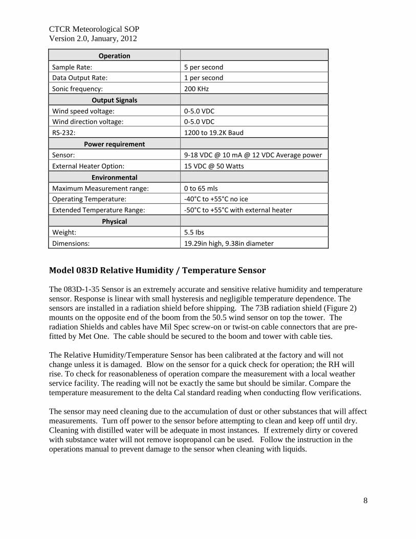
CTCR Meteorological SOP
Version 20 January 2012
8
Operation
Sample Rate 5 per second
Data Output Rate 1 per second
Sonic frequency 200 KHz
Output Signals
Wind speed voltage 0-50 VDC
Wind direction voltage 0-50 VDC
RS-232 1200 to 192K Baud
Power requirement
Sensor 9-18 VDC 10 mA 12 VDC Average power
External Heater Option 15 VDC 50 Watts
Environmental
Maximum Measurement range 0 to 65 mls
Operating Temperature -40degC to +55degC no ice
Extended Temperature Range -50degC to +55degC with external heater
Physical
Weight 55 Ibs
Dimensions 1929in high 938in diameter
Model 083D Relative Humidity Temperature Sensor
The 083D-1-35 Sensor is an extremely accurate and sensitive relative humidity and temperature
sensor Response is linear with small hysteresis and negligible temperature dependence The
sensors are installed in a radiation shield before shipping The 73B radiation shield (Figure 2)
mounts on the opposite end of the boom from the 505 wind sensor on top the tower The
radiation Shields and cables have Mil Spec screw-on or twist-on cable connectors that are pre-
fitted by Met One The cable should be secured to the boom and tower with cable ties
The Relative HumidityTemperature Sensor has been calibrated at the factory and will not
change unless it is damaged Blow on the sensor for a quick check for operation the RH will
rise To check for reasonableness of operation compare the measurement with a local weather
service facility The reading will not be exactly the same but should be similar Compare the
temperature measurement to the delta Cal standard reading when conducting flow verifications
The sensor may need cleaning due to the accumulation of dust or other substances that will affect
measurements Turn off power to the sensor before attempting to clean and keep off until dry
Cleaning with distilled water will be adequate in most instances If extremely dirty or covered
with substance water will not remove isopropanol can be used Follow the instruction in the
operations manual to prevent damage to the sensor when cleaning with liquids
CTCR Meteorological SOP
Version 20 January 2012
9
Figure 2 Model 073B Radiation Shield
Table 8 Model 083D RH and Temp Sensor Specifications
Sensing Element Thin-film Capacitor
RH Range 0 - 100
Temp Range -50deg to +50degC
Response Time 15 seconds at 20degC
RH Accuracy plusmn2 RH between 10 and 100 RH
Temp Accuracy 01degC
Hysteresis For 0 to 100 to 0 excursion le 1
Temperature Coefficient plusmn004 per 1degC
Output 0 - 1 V full scale
Input Power 12V DC
Barometric Sensor 090D
The 090D (2632-1) uses an active solid-state device to sense barometric pressure with a range of
26 to 32 inches of mercury and a voltage output of 0 ndash 1 volt The sensor attaches to the tower or
other convenient location with a ldquoJrdquo bolt Orient the J box with the pressure inlet port facing
down Install the cable through the water tight fitting and connect as shown in Figure 2
CTCR Meteorological SOP
Version 20 January 2012
10
Figure 3 Installing the Barometric Sensor 090D Wiring
The sensor has been calibrated at the factory and will not change unless damaged No field
modification or calibrations can occur To check for proper operation compare to a local
weather station to see if the readings are reasonable The measurement will not be exactly the
same due to differences in elevation and measurement parameter absolute or normalized to sea
level This sensor measures absolute inches of mercury BP can also be checked when
conducting regular flow verifications or calibrations on the BAM 1020 The deltaCal standard
measures BP as millimeter (mm) or millibars (mb) and can be converted to inches mercury by
multiplying mm X 03937 and mb X 00295
Maintenance consists of inspecting the pressure inlet port for blockages and removing
obstructions if found If service or recalibration becomes necessary then send the sensor to the
manufacture
Rain Gauge 375 001 Inches This sensor measures precipitation on a continuous basis and is low-maintenance The tipping
bucket collects 001 inches of precipitation then tips and drains This triggers a switch closure
pulse that is counted The tipping bucket and rain gauge are heated to prevent accumulation of
snow and ice The sensor has been calibrated at the manufacture and should not require
adjustments after installation Mount the sensor level on a platform using the built in level and
three adjusting legs Follow the instruction in the operations manual (Appendix F) for complete
installation instructions A debris screen should be removed during the winter when snow will
accumulate
After installation manually actuate the tip bucket mechanism three times and confirm the tips
have registered on the data logger Inspect and clean the tipping buckets periodically and
physically tip to verify recording on the data logger If the sensor has been damaged or appears
to need calibration follow the instruction in the operations manual
Table 9 Model 375C Rainfall Sensor Specifications
Orifice 8 Inch Diameter
Calibration 01 Inches Rain per Switch Closure
Accuracy plusmn 1 at 1 to 3 inches per hour at 70 Fdeg
Switch Type Magnet and Reed
Mounting 3 Pad for 14 inch bolts
Dimensions 8 Inch Diameter
CTCR Meteorological SOP
Version 20 January 2012
11
Power Requirement 110 VAC
Weight 75 Pounds
Quality Control and Quality Assurance Quality Control (QC) and Quality Assurance measure are minimal due to the reliability and low
maintenance of the meteorological sensors employed The following table list all standards
used maintenance needed and actions If sensors exhibit characteristics outside of these
parameters the manufacturer will be contacted for instructions Records related to Meteorological
sensors will be tracked on the site log and summaries semiannually
Table 10 Meteorological Sensor Quality Control and Assurance Measures
Sensor Criteria Action
BX-596 ATBP Sensor
BP varies more than plusmn10 mm Hg from deltaCal Standard BAM 1020 Calibration Following SOP
Temperature varies more than plusmn2degC from deltaCal Standard BAM 1020 Calibration Following SOP
Sensor shield andor probe damaged Contact Met One for instructions
BX-592 Outside Temperature Sensor Volumetric Flow
Temperature varies more than plusmn2degC from deltaCal Standard BAM 1020 Calibration Following SOP
Temperature shield andor probe damaged Contact Met One for instructions
Model 505 Wind Sensor
Yearly zero test reading 00 to 01 ms wind speed
Contact Met One for instructions if greater than these readings
Yearly span test
Contact Met One for instructions if readings do not match those shown in Table 6
Heater not functioning Contact Met One for instructions
Relative HumidityTemperature
Sensor 083D
Yearly check for reasonableness Compare with local weather station
Yearly check for operation Blow on sensor and confirm RH rise
Barometric Sensor 090D Yearly inspection
Clean pressure inlet port for blockages when needed
Compare to deltaCal Standard Contact Met One for instructions if values do not compare reasonably
Rain Gauge 375 001 Inches
Yearly check for operation Manually tip bucket and confirm reading
Yearly check for level Use adjustment legs to level
Damage or bucket set screws loose
Follow instructions in operation manual for calibration
CTCR Meteorological SOP
Version 20 January 2012
12
Reference EPA Requirements for Quality Assurance Project Plans EPA QAR-5 Office of Environmental
Information Washington DC EPA240B-01003 March 2001
Guidance for Quality Assurance Project Plans EPA QAG5 Office of Environmental
Information Washington DC EPA240R-02009 December 2002
Guidance for Preparing Standard Operating Procedures (SOPs) EPA QAG-6 Office of
Environmental Information Washington DC EPA6000B-07001 April 2007
Met One Instruments Inc (2008) BAM 1020 particulate monitor operation manual Prepared by
Met One Instruments Inc Grants Pass OR BAM-1020-9800 Rev G
Standard Operating Procedure for the Continuous Measurement of Particulate Matter Monitoring
Sites Confederated Tribes of the Colville Reservation Air Quality Program August 2011
CTCR Meteorological SOP
Version 20 January 2012
13
Appendices
BX-596 ATBP SENSOR MANUAL
Met One Instruments Inc 1600 Washington Blvd Grants Pass Oregon 97526 Telephone 541-471-7111 Facsimile 541-541-7116
BX-S9G Sensor Manual - copy Copyright 2007 Met One Instruments Inc All Rights Reserved worldwide No part of this publication may be reproduced transmitted transcribed stored in a retrieval system or translated into any other language in any form without the express written permission of Met One Instruments Inc
Appendix A BX-596 ATBP Sensor Operation Manual
About this Manual
The BX-596 is an optional combination ambient temperature and barometric pressure sensor for use with the BAM-1020 particulate monitor The BX-596 sensor is a required accessory for all BAM-1020 configured to sample PM25 levels effective March 2007 The sensor provides ambient temperature and pressure data to the unit for actual (volumetric) flow control and flow statistics during the hourly sample cycle The BX-596 is only compatible with BAM-1020 firmware version 324 or later This manual describes the installation and operation of the BXshy596 sensor Refer to the BAM-1020 operation manual as needed
The BX-596-1 is an extended range version for extreme cold or high altitude environments
BX-59G TemperaturePressure Sensor Installed on a BAM-1020 Inlet Tube
Specifications
I
I I
I
I
I I
BX-59G Barometric Pressure Ambient Temperature Voltage Output o to 25 volts o to 25 volts
Range 525 to 825 mmHg -40 to +55 deg C Accuracy plusmn025 mmHg 25 C plusmn 15C above -30
10 Voltage 350 volts DC plusmn 02
BX-59G-1 Barometric Pressure Ambient Temperature i
Voltage Output o to 25 volts o to 25 volts Range 400 to 825 mmHg -50 to +50 deg C
Accuracy plusmn15 mmHg plusmn 15C full scale 10 Voltage 410 volts DC plusmn 02
BX-596-98DD Manua RevBdoc Page 1 of 4
Appendix A BX-596 ATBP Sensor Operation Manual
Installation and Setup
Ensure that the BAM-1020 is sited and installed properly per the instructions in the operation manual
During the installation process you will need to provide an access point for the BX-596 sensor cable to enter the shelter where the BAM-1020 is installed In some cases it is easiest to simply drill a 38 hole through the roof of the shelter about six inches away from the inlet tube then feed the cable through the hole and caulk around it to prevent leaks
There may be a better place to feed the cable into the shelter in some applications The BXshy902903 environmental shelters supplied by Met One have pre-formed access holes in the side to allow the sensor cable to be routed to the BAM-1020 Decide the best way to route the cable into the shelter The BX-596 comes with a standard 25-foot sensor cable Longer cables may be ordered if required
Remove the PM 10 head and PM25 cyclone from the top of the BAM inlet tube Attach the BXshy596 to the inlet tube (about 8 to 18 inches from the top) with the supplied U-bolt hardware Make sure that the sensor is level and tighten the U-bolt securely
Make sure the BAM-1020 is turned off then attach the sensor cable to the connector on the bottom of the BX-596 Route the loose end of the cable into the shelter and to the back of the BAM-1020 Coil up any excess length of cable Attach the cable to the back of the BAM as shown in the following table
I
BX596 ATBP Sensor Connections Wire Color Function BAM Terminal
Yellow A T Signal Output Channel 6 SIG BlackShield Ground Channel 6 COM Red +12 VDC Channel 6 POWER Green Auto 10 Signal 350V Channel 6 10 White BP Signal Output Channel 7 SIG
Reinstall the PM10 head and PM25 cyclone and seal around the cable hole with silicone if required
Operation
When the BAM-1020 is powered up with a BX-596 installed the unit will automatically sense the 10 voltage from the sensor and configure input channels six and seven to read and scale the outputs from the sensor Note The BX-596 sensor requires BAM-1020 firmware revision 320 or later The BX-596-1 extended range version requires BAM-1020 firmware revision 362 or later If the BAM firmware is not current enough then the BAM will not automatically identify and scale the sensor
Appendix A BX-596 ATBP Sensor Operation Manual
Turn ON the BAM-1020 and perform a calibration of the BX-596 Note The calibration is performed in the TESTgt FLOW screen which will not be available unless the FLOW TYPE is set to ACTUAL in the SETUPgt CALIBRATE screen You will need a reference standard measurement for ambient temperature and barometric pressure
MULTIPOINT FLOW CALIBRATION TARGET BAM STD
ltCALgt ~~~ 238 238 C BP 760 760 mmHg
FLOW 1 150 150 150 LPM FLOW 2 183 183 183 LPM FLOW 3 167 167 167 LPM
CAL NEXT DEFAULT EXIT
1 Enter the TESTgt FLOW menu as shown above The nozzle will lower automatically when this screen is entered The BAM colurnn is what the BAM-1020 measures for each parameter and the STO column is where you will enter the correct values from your reference standard The ltCALgt symbol will appear next to the parameter selected for calibration
2 Measure the ambient temperature with your reference standard positioned near the BXshy596 sensor Enter the value from your reference standard into the STO field using the arrow keys Press the CAL hot key to correct the BAM reading The BAM and STO values should now be the same
3 Press the NEXT hot key to move the ltCALgt indicator to the BP field and repeat the same steps for barometric pressure
The DEFAULT hot key can be pressed to reset the user calibration from the selected parameter and replace it with a factory setting The DEFAULT calibration should be fairly close in most cases
The BX-596 sensor is almost always calibrated as part of a BAM-1020 flow calibration Always calibrate the AT and BP channels before calibrating the flow channels as the flow rate is affected by the temperature and pressure of the ambient air
The 8X-596 temperature output may also be checked in an ice bath The ice bath test is usually never done except in some cold weather environments First calibrate the sensor at ambient temperature then use the following steps
1 Remove the stop screw from the bottom of the mounting bracket so that the electronics module is free to rotate Rotate the module counter-clockwise until it disengages from the keyhole slots and comes free from the radiation shield
2 The sensor comes with an 18 inch long ice bath extension harness This may be used to allow the temperature bead to reach the ice bath if necessary Carefully unplug the black temperature bead assembly from the top of the electronics module and install the harness between the bead and the module
3 Insert the temperature bead into the ice water bath along with your reference sensor Avoid immersing the bead assembly past the connector
Appendix A BX-596 ATBP Sensor Operation Manual
4 Allow the bead to equilibrate then compare the AT reading in the TESTgt FLOW screen to your reference sensor The readings should match within plusmn15 degrees C for the BXshy596-1 extended range sensor Note The tolerance for the regular BX-596 standard range sensor is plusmn 25 C in temperatures below -30C
5 Remove the ice bath harness and reassemble the sensor
During operation of the BAM-1020 the output from the BX-596 can be viewed from the main flow statistics screen or the OPERATE screens See the BAM-1020 manual
JI -~J
1 1~
i gt
-- --- shyv_
Ice Bath Extension Harness
Maintenance The BX-596 is designed to be low-maintenance easy to access and resistant to harsh environments There are only a few maintenance items for the sensor besides routine calibration checks
bull Remove the bottom cover and make sure that the four holes in the cover plate are clear and have not been obstructed by insects or debris These holes allow the air pressure to equilibrate inside the sensor for the barometric pressure reading Clean the inside of the electronics enclosure every 12 months or as needed
bull Clean the radiation shield assembly at least once per year Dirty shields reflect away solar radiation less efficiently
bull The circuit board is not intended to be removed or serviced by the customer bull The black temperature bead assembly may be replaced if the bead becomes damaged
The assembly simply plugs into the top of the electronics module The sensor will need to be recalibrated any time the temperature bead is replaced
Technical Support
Should you still require support after consulting your printed documentation we encourage you to contact one of our expert Technical Service representatives during normal business hours of 700 am to 400 pm Pacific Standard Time Monday through Friday In addition technical information and service bulletins are often posted on our website Please contact us and obtain a Return Authorization (RA) number before sending any equipment back to the factory This allows us to track and schedule service work and expedite customer service
Phone (541)471-7111 Fax (541)471-7116 E-Mail servicemetonecom Web wwwmetonecom
Mail Technical Services Department Met One Instruments Inc 1600 NW Washington Blvd Grants Pass OR 97526
Appendix A BX-596 ATBP Sensor Operation Manual
warranty
Products manufactured by Met One Instruments Inc are warranted against defects in material and workmanship for a period of one (1) year from the date of shipment from the factory Offered products not manufactured by Met One Instruments Inc will be warranted to the extent and in the manner warranted by the manufacturer of that product
Any product found to be defective during the warranty period will at the option of Met One Instruments Inc be replaced or repaired In no case shall the liability of Met One Instruments Inc exceed the purchase price of the product
This warranty may not apply to products that have been subject to misuse negligence accident acts of nature or that have been altered or modified other than by Met One Instruments Inc Consumable items such as bearings and batteries are not covered under this warranty
Other than the warranty set forth herein there shall be no other warranties whether expressed implied or statutory including warranties of fitness or merchantability
Service
Ary product being returiled to Met One Instruments In for service repair or calibration must be assigned a return authorization (RA) number Please call (541) 471-7111 or (972) 412-4715 for an RA number and shipping instructions
Products manufactured by Met One Instruments Inc that are returned for service repair or calibration are warranted against defects in material and workmanship for ninety(90) days from date of shipment under the same conditions as stated above
999
Appendix A BX-596 ATBP Sensor Operation Manual
Temperature Probe amp Shield Model BX-592
Operation Manual BX-592-9800
1600 Washington Blvd Regional Sales amp Service Grants Pass Oregon 97526 3206 Main St Suite 106
Met One Instruments
Telephone 541-471-7111 Facsimile 541-541-7116
Rowlett Texas 75088 Telephone 972-412-4715 Facsimile 972-412-4716
Appendix B BX-592 Temperature Probe and Shield Operation Manual
Model BX-592 Temperature Probe amp Shield Operation and Installation Manual
INTRODUCTION The Model BX-592 is a temperature probe and shield for use with the BAM-1020 particulate analyzer The BX-592 is used specifically with the BX-962 Volumetric Flow Control System used on the BAM-1020 This sensor provides temperature measurement of the outside air used to determine the temperature correction value as part of the volumetric flow calculation The sensor is designed to be connected directly to one of the analog input channels of the BAMshy1020 The BX-592 is used when there is no other source of analog temperature output from an existing temperature system at the owners location The BX-592 includes 30 ft of cable as well as a mounting adapter that attaches to the inlet tube of the BAM-1020
INSTALLATION The BX-592 is installed outside near the intake of the BAM-1020 particulate analyzer Mounting hardware is provided for direct mounting on the BAM-1020 inlet tube as shown in figure 10 Attach the temperature probe and shield to the horizontal bar using the clips on the top of the temperature shield Push the shield up onto the horizontal bar and press the grey plastic clips together until you hear the snap of the retainer locking inplace
The fitting on the mounting arm should be mounted in a convenient place near the top of the inlet tube and out of the way of the supports used to hold the inlet tube in place Tighten the set screws on the mounting adapter to hold it in place on the inlet tube The horizontal bar can be moved as necessary to mount the shield in a suitable location near the inlet tube and the PM-10 or PM-25 inlet assembly
The cable from the sensor can then be run down through the roof of the shelter or building so that it can be connected to the sensor input channel terminal block on the back of the BAMshy1020 unit
Figure 1 Temperature Sensor Installation
BX-592 Manual 31JAN2001 2
Appendix B BX-592 Temperature Probe and Shield Operation Manual
The sensor input connection should be made at sensor location six This input channel is the one used for any external temperature analog input used for the temperature correction input required by the volumetric flow controller
The BX-592 Temperature Sensor and Shield provides a special ider1tification output signal that is used by the BAM-1020 to determine what type of sensor is connected to the BAM as well as determine what the range of the temperature sensor The electrical connections to the BAMshy1020 can be see in Figure 2 Be sure that the color code of the individual wires of the cable is followed so that the sensor is not connected incorrectly to the BAM-1020 There are four wires which are connected to the four terminals of the analog inputs at the back of the BAM unit
IO~=== laquo) SIG ~2P-~~~WHTd COM ~~BLK ----~_4z ~ PWR ~2P-REO ----- I I 0 ~d)J-GRN --shyUL=== ~
SIG ~
Figure 2 Sensor Connections to BAM
Figure 2 shows the connections from the BX-592 Temperature Sensor and Shield to the BAMshy1020 Particulate Analyzer Be sure that the temperture sensor cable is connected to channel 6 of the BAM-1020 otherwise the voltage output of the sensor will not be able to be used as the temperature reference of the volumetric flow controler
For correct operation of the volumetric flow control option BX-961 the BAM-1020 must be programmed for volumetric flow operation This is done from the SETUP then CALIBRATE and then FLOW TYPE screen The default is metered flow and will need to be set for volumetric flow for tt1ts option to work correctly See the BAM-1020 Manual section 414 for information on the Calibrate Screen and in section 63 for information on the field calibration of the flow system
SPECIFICATIONS The following are the specifications of the BX-592 Temperature Sensor and Shield These are subject to change as determined by Met One Instruments Inc The shield of the BX-592 provides protection of the temperature probe from errors that are caused by direct solar radiation The shape allows for the wind to naturally aspirate the shield to reduce the total effect of solar radiation on the temperature measurement
Temperature Probe Type Thermistor Bead multi-element
Temperature Accuracy
Temperature Range
Sensor Output o to 1 VDC for temperature range
Time Constant 10 Seconds in still air
BX-592 Manua13IJAN2001 3
Appendix B BX-592 Temperature Probe and Shield Operation Manual
The shield is mounted from the top of the shield using two snap clamps designed for a 1 diameter tube or a IPS Pipe The mounting adapter and a short boom are provided for attachment to the inlet tube of the BAM-1020
MAINTENANCE amp CALIBRATION The temperature probe and shield require no specific maintenance other than normal cleaning of dirt and dust to prevent the degredataion of the reflectiveness of the shield If there is any build up of materials inside the shield they should be cleaned out so that there is a free path for air flow around the temperature probe
On a regular basis the output of the temperature probe displayed on the screen of the BAMshy1020 should be checked against a reference thermometer to be sure that the BX-592 is providing accurate information for the calculation of volumetric flow There are no adjustments inside the temperature probe and any repairs should be handled by the factory
Before returning a faulty probe the factory should be contacted a RA (Return Authorization) should be obtained and the problem noted on the RA This will insure that the repairs are made quickly and returned for installation
TROUBLE SHOOTING
Symptom Identify Problem Solution Incorrect Temperature indicated on BAM Display
Verify that connections to the rear panel of the BAM are correct and to channel 6
Change wiring to follow diagram as indicated in figure 2 of this manual
From setup menu channel Change settings from parameters screen verify that MANUAL Mode to Auto ID channel 6 is set for Auto ID mode for probe to work and not in MANUAL Mode correctly Examine output of BX-592 to Using a volt meter measure verify that it has the correct voltage between the black and voltage output for the current white wires 0-1 volt is ambinet temperature equivalent to -30 to 50
degrees C Le 21degC =637 volts If this is not correct return probe for repair
Volumetric Flow Control is not operating
Go to the Setup then Calibrate screen menu and verify that the flow type is set to volumetric and not metered
Default setting is for metered it will be necessary to change setting to volumetric flow type
Examine rear of BAM-1020 and see if there is a flow adjusment knob on the back of the unit right above the vacuum line
If there is a knob here it is most likely that volumetric flow control is not installed on this unit Contact Met One Instruments for advice
Volumetric flow value does not match audit flow meter connected to BAM
From setup menu select flow and examine the current measured flow value of the BAM
Recalibrate the BAM flow meter using the proceedure in the manual section 63 Field Calibration of Flow System
Verify that the audit instrument being used has been calibrated for volumetric flow monitoring
Adjust flow audit device for correct measurement of volumetric flow
BX-592 Manual 3IJAN200 1 4
Appendix B BX-592 Temperature Probe and Shield Operation Manual
For any other specific problems with the BX-592 or the Volumetric Flow Option BX-961 contact the factory
Met One Instruments Inc 1600 NW Washington Blvd Grants Pass Oregon 97527
(541) 471-7111 Voice (541 ) 471-7116 FAX
service metonecom e-mail
Visit our web page at httpwwwmetonecom
BX-592 Manual 31JAN2001 5
Appendix B BX-592 Temperature Probe and Shield Operation Manual
MODEL 505 WIND SENSOR
OPERATION MANUAL Document No 505-9800
1600 Washington Blvd Grants Pass Oregon 97526
Met One Telephone 541-471-7111 Instruments Facsimile 541-541-7116
Regional Sales amp Service 3206 Main St Suite 106 Rowlett Texas 75088 Telephone 9724124715 Facsimile 972-412-4716
505-9800 Rev Edoc
Appendix C Model 505 Wind Sensor Operation Manual
Copyright Notice
505 Sonic Wind Sensor Manual
copy Copyright 2005 Met One Instruments Inc AI Rights Reserved Worldwide No part of this publication may be reproduced transmitted transcribed stored in a retrieval system or translated into any other language in any form by any means without the express written permission of Met One Instruments Inc
Technical Support Should you require support please consult your printed documentation to resolve your problem If you are still experiencing difficulty you may contact a Technical Service representative during normal business hours-730 am to 400 pm Pacific Standard Time Monday through Friday
Voice (541) 471-7111
Fax (541) 471-7116
E-Mail servicemetonecom
Mail Technical Services Department Met One Instruments Inc 1600 Washington Boulevard Grants Pass OR 97526
505-9800 Rev E Page 2
Appendix C Model 505 Wind Sensor Operation Manual
TABLE OF CONTENTS 1 GENEAAL INFORIIATION 5
2 INSTALLATION 5
21 LTNPACKlNG 5 22 PREPARATION 5 23 SENSOR SITING 6
Figure 2-1 Siting Wind Instroments 6 24 ORIENTATION WITH FIXTURE 7
Figure 2-2 Orientation Fixture 7 25 ORIENTATION WITHOUT FIXTURE (SEE FIGURE 2-3 AND 2-4) 8 26 EXTERNAL HEATER 8
Figure 2-3 505 Wind Sensor Components 9 Figure 2-4 Alignment aSensor to Troe North 10
27 INSTALLATION OF AVERY DETERRENTS 11 Figure 2-5 InstallatIOn ofAviary Delerrents I
28 CONNECTIONS TO RECORDING ELECfRONICS 12
Figure 2-7 Factory Standard Analog amp Rf-232 Output Connections (Cable 9574 wi Differential Amplifier
Figure 2-8 Factory Custom SDI-12 Output Connections 3
Figure 2-6 Amplifier (9573) attached to Cable (9574) and wiring in box 12
9573) 12
Figure 2-9 Factory Custom RS4221485 Output Connections 13 28 SIGNAL OUTPUTS ANALOG RS-232 ANDSDI-12 13 29 SIGNAL OUTPUTS - RS422 AND RS485 14
3 OPERATIONAL CHECK-OUT AND CALmRATION 14
31 GENERM 14 32 RECORDING ELECTRONICS 14 33 ZERO TEST 14 34 SPAN TEST 14
4 MAINTENANCE AND TROlTBLESHOOTING 15
41 GENERAL MAlNTENANCE SCHEDULE 15 42 TROlTBfJESHOOTING 15
5 TIIEORY OF OPEAATION 16
51 SPEED OF SOUND IN AlR 16 52 SPEED OF S()UND PRINCIPLE 16 53 CALCULATION OF THE WIND VELOCITy 16
6 SPECIFICATIONS 17
FIGURE 6- 505 Wind Sensor Outline Dimensions 18
APPENDIX A - WIND DIRECTION SENSOR ORIENTATION 19
APPENDIX B - WIND SENSOR MOUNTING OPTIONS 22
APPENDIX C - HEATER CONFIGURATION AND WIRING 23
APPENDIX D - RS2J2 COMMAND SET 25
GENERAL PROTOCOL 25
1 RS-2J2 DATA OUTPUT PROTOCOL 25
11 ERROR CODE 26
2 USER COMMAND SET _ 27
21 L8-VERBOSE CONTROL OF RS-232 PARAMETER LABELS 27
505-9800 Rev E Page 3
Appendix C Model 505 Wind Sensor Operation Manual
22 MS-MAxLMUM FULL SCALE WIND SPEED 27 23 SU-WINO SPEED UNITS 27 24 QU-QUlT 27 25 SB-SERIAL BAUD RATE 28 26 ST-SERIAL TRIGGER (RS-485 ONLy) 28 27 IT-SONIC TEMPERATURE 28 28 VN-VERSION NUMBER 28 29 VS-FULL SCALE ANALOG OUTPUT VOLTAGE FOR WINO SPEED Ai~O WINO DIRECTION 28
505-9800 Rev E Page 4
Appendix C Model 505 Wind Sensor Operation Manual
MODEL 505 WIND SENSOR OPERATION MANUAL
1 GENERAL INFORMATION
The Met One Instruments Model 505 Wind Sensor is a solid-state ultrasonic instrument capable of measuring wind speed and wind direction in the U and V axes Sonic pulses are generated at the transducers and are received by opposing transducers Mathematics derived for these sonic pulses provide a wind velocity measurement in each of the corresponding axes
The 505 uses a microprocessor-based digital electronic measurement system to control the sample rate and compute the wind speed and wind direction The sensor is factory calibrated and requires no field calibration In the field the operation of the sensor can be quickly checked using a combination of simple tests A zero chamber or bag is used to verify the zero reference by covering the entire sensor or individual outputs are checked by blocking various combinations of sensors
The 505 provides are variety of outputs to suit the connection requirements of the user Standard outputs are voltage and RS-232 SDI-12 and RS422485 outputs are configured at the factory
2 INSTALLATION
21 UNPACKING
Carefully remove the sensor from its shipping container and inspect it for damage Referring to the packing list check for shortages Any claims for damages should be filed promptly with the carrier
The sensor is a precision electromechanical transducer Always handle it with care exercising particular caution to ensure that the instrument is not subjected to side loading shock or other abuse After initial inspection keep the sensor in its shipping container for protection until actual installation
22 PREPARATION
For accurate measurements the sensor mount must be rigid with little or no movement from the wind The sensor is designed for installation in a Model 3188 mounting and alignment fixture This provides a mount for use on a horizontal IPS pipe (105- 00) boom Mounting information and diagrams can be found in Appendix B of this manual
The 3188 Sensor Mounting Fixture includes a keyed bushing which will be adjusted for alignment to North orientation This enables the sensor to be removed and replaced without requiring realignment Three captive machine screws are used to secure the sensor to the keyed bushing
If a temperature shield such as the Model 0738 is to be used in the configuration the Model 1539-4 Arm and 1552 Mount is recommended These parts provide the necessary mounting for a vertical mast of 0 IPS pipe (105 OD) This same configuration can also be used to mount other sensors as well as providing a way to mount the sensor on a vertical mast (See Appendix B for Mounting Details)
505-9800 Rev E Page 5
Appendix C Model 505 Wind Sensor Operation Manual
23 SENSOR SITING
The primary objective of instrument siting is to place the instrument in a location where it can make precise measurements that are representative of the general state of the atmosphere in that area Because most atmospheric properties change dramatically with height and surroundings certain somewhat arbitrary conventions must be observed so that measurements can be compared
lOT
Figure 2-1 Siting Wind Instruments
The standard exposure of wind instruments over level open terrain is 10 meters above the ground (WMO 1971) however optimum measurement height may vary according to data needs Open terrain is defined as an area where the horizontal distance between the wind sensor and any obstruction is at least ten (10) times the height of that obstruction An obstruction may be man-made (such as a building) or natural (such as a tree) (See Figure 2-1)
The wind instrument should be securely mounted on a mast that will not twist rotate or sway If it is necessary to mount the wind instrument on the roof of a building it should be mounted high enough to be out of the area in which the airflow is disturbed by the building This is usually 15 times the height of the building above the roof so that it is out of the wake of the obstruction This is not a good practice however and should only be resorted to when absolutely necessary
Wind instruments are best sited when they are used on towers The tower should be located in an open level area representative of the area under study Towers should be of the open grid type of construction such as is typical of most television and radio broadcast towers Enclosed towers stacks water storage tanks grain elevators cooling towers and similar structures should not be used
Wind instruments should be mounted above the top of the tower on booms projecting horizontally out from the tower If a boom is used it should support the sensor at a distance equal to minimum of twice or at best three times the maximum diameter or diagonal of the tower away from the nearest point on the tower On large towers with large verticals it may be best to place the sensor at least 5 tower leg diameters from the tower leg The boom should project into the direction which provides the least distortion for the most important wind direction For example a boom mounted to the east of the tower will provide least distortion for north or south winds
505-9800 Rev E PageS
Appendix C Model 505 Wind Sensor Operation Manual
Weather sensors are sensitive to direct or nearby lightning strikes A well-grounded metal rod or frame should be placed above the sensor installation In addition the shield on the signal cable leading to the translator must be connected to a good earth ground at the translator end and the cable route should not be vulnerable to lightning
24 ORIENTATION WITH FIXTURE
The Orientation Fixture Model 705 is used for very accurate positioning of the 505 sensor with respect to a benchmark or other object that can be visually obselVed If a compass is used to establish a benchmark the reading should be taken away from heavy metal objects which can affect the reading and should be corrected for declination of the magnetic north pole The benchmark is set to true north of the sensor site Information on determining true North can be found in Appendix A of this manual
The fixture contains a telescopic sight with crosshairs and includes a keyed base identical to that on the sensor The fixture is specifically designed for use with the 3188 Sensor Mounting Fixture The base of the fixture is keyed so that the object lens of the sight assumes the same position as the north side of the sensor
Before orienting the sensor ensure that it is vertical and adjust the cross arm as necessary Orientation of the sensor is then performed with the fixture installed on the cross arm in place of the sensor (The three screws in the base of the fixture must be tightened to ensure proper orientation in the cross arm) Loosening the three setscrews on the side of the sensor mount allows free rotation of the keyed bushing and orientation fixture The ring and fixture are then rotated to position the benchmark in the center of the sight crosshairs The sight can be tilted as necessary by loosening the slotted screw on the side of the fixture The set screws are then tightened the fixture removed and the sensor installed in its place The sensor is now oriented for zero (north) wind direction signal output when the wind is from north
OSIECTlENS
Figure 2 2 Orientation Fixture
The electrical connector on the bottom of the sensor should be properly mated to the cable connector and the three captive screws on the base of the sensor should be tightened
When using the orientation fixture assure that the two-piece mounting assembly is properly aligned The upper half of the assembly contains a horizontal peg which must seat in the vshynotch located in the lower half The knurled knob on the lower half is used to secure the two sections and should be tight
505-9800 Rev E Page 7
Appendix C Model 505 Wind Sensor Operation Manual
25 ORIENTATION WITHOUT FIXTURE (See FIGURE 2-3 and 2-4)
Establish a True North benchmark See Appendix A for aids to determine True North This should be a point directly north from the sensors mounted location This point should allow easy access so that a person may sight the sensor with a spotting telescope If a compass is used to establish a benchmark the reading should be taken away from heavy metal objects which can affect the reading and should be corrected for declination of the magnetic north pole The benchmark is set due north of the sensor site
One person is located at True North benchmark equipped with a spotting scope A second person is located at the sensor The sensor alignment may be established as follows
A Install the sensor into the alignment bushing and secure with the two setscrews under the 3188 Alignment Fixture Keep the three setscrews around the ring of the fixture loose so that the ring can be rotated into position
B Turn the sensor so that the sensor paints to the North benchmark Tighten the 3 setscrews and recheck align ment
C Connect the 9574-cable assembly to the sensor Secure cable to boom with cable ties or tape to prevent damage
D The sensor can be removed without requiring realignment at any time Simply remove the sensor The alignment bushing remains proper1y oriented in the fitting
26 EXTERNAL HEATER
The Optional External Heater provides de-icing for the sensor arms and prevents the accumulation of ice which might block the sonic sensor elements The heater consists of a laminated heater material that is custom designed and wrapped around the four sensor arms and sonic sensor element housings The heater controller requires 15 to 24 VACNDC at approximately 4-5 amps at startup There are jumper connections on the controller board for the selection of power source The controller is normally provided with the jumpers not installed This is for 24 volts AC operation of the heaters Heater power can be supplied from a power transformer or a Met One Instruments supplied power unit in a weatherproof box The proportional controlled heater uses maximum current at start-up and power requirement goes down as the sensorheater reaches stability The heater is activated at 38 degrees F and will keep the arms ice-free at temperatures down to below -20 degrees F The connection information can be found in Appendix C of this manual
The temperature controller electronics box should be mounted no more than 5 feet from the sensor using the cable supplied with the heater controller The power cable should be of minimum 16 AWG wire and cable length should be at a minimum to prevent power loss due to cable resistance at the 4-amp power requirement
505-9800 Rev E Page 8
Appendix C Model 505 Wind Sensor Operation Manual
MODEL 505 WINO SENSOR
NORTH SCREWPIN ____~~--
THIS SIDE TO FACE SOlTTH LABEL
NORTH SLOT HOLE~middot-c-lIIo-
SET SCREWS (3 EA FOR SECURING
KEYED BUSHING TO HORTH ORIENTATION
(7164- ALLEN KEY)
Figure 2-3 505 Wind Sensor Components
Page 9 505-9800 Rev E
Appendix C Model 505 Wind Sensor Operation Manual
SOUTHSIDE SENSOR TRANSDUCER SHOULD BE SEEN EaUALLY DIVIDED
BY NORTHSIDE (NEAR) ARM
Figure 2-4 Alignment of Sensor to True North
505-9800 Rev E Page 10
Appendix C Model 505 Wind Sensor Operation Manual
27 INSTALLATION OF AVERY DETERRENTS
To prevent birds from entering the pathway between the sensors a vertical stainless steel rod is located in the center of the sensor array_ To keep birds from perching on the sensors stainless steel wire aviary deterrent need to be installed on the sensor prior to installation in the fixture
NOTE The stainless steel wires used for the aviary deterrents are very sharp The wire is spring steel and there s the possibility that it could slip off during the installation Use care
when installing the aviary deterrent and be careful after installation
PROTECTIVE GLASSES SHOULD BE WORN DURING INSTALLATION
Installed A viarv Deterrents
area
AVIARY DETERRENTS bull PIIIih ends IowaIds eoch ltlttler lil qgten up
spring d1amccr bull Slide owr lranllducer 10 mounIing llIII bull ~6l as requRd 60 that avlary
delemK1N are pointed ~
MOUNTING AREA
Figure 2-5 Installation of Aviary Deterrents
WARNING If the aviary deterrents are not properly installed The sensor may experience signal degradation Install as shown DO NOT allow for the spring section of the aviary deterrent to contact the transducer portion of the sensor array_
505-9800 Rev E Page 11
Appendix C Model 505 Wind Sensor Operation Manual
28 CONNECTIONS TO RECORDING ELECTRONICS
Route the cable to the data-recording device Secure the cable with cable ties or tape The 9574shycable assembly contains 7 wires and a shield Typical wiring hookup is shown in the figures below Actual wiring will depend upon the version of the sensor To determine which of the three connections drawings apply examine the cable part number at both ends of the cable
Cable type 9574 includes the 9573 Differential Amptifier it is located at the end of the cable opposite the sensor connector The amplifier provides high immunity to any noise that might be picked up the sensor cables It is recommended that this cable with amplifier be used whenever connected to a single ended input recorder If necessary to remove the differential amplifier a wiring diagram has been included in the top of the small amplifier enclosure A small screwdriver is provided for use on the small terminal screws on the PC Board of the 9573 Amplifier Be sure that the connection color codes are followed so that no wiring error occurs See below
Warning If you are connecting this 505 to an older 3155-cable assembly and are using the black wire as signal common disconnect it because it will short out the RS-232 transmitter No damage will occur to the circuit but the 505 current consumption will increase by 20 rnA
TO SONIC
~ n 0 SHLD (WTIBN) +12Y(Wiri) 0 0 NIC wo oOt-(RpoundD 0 0 GND(GRN) WD 0lIT~ (OAN) 0 0 ncD(8LK) W8 ~+(BLU) 0 0 RXC(IRN) NC 0 0 WSIN+(BW) RXD(8fCN) 0 0 NIC TXDl8LJC) 0 0 WDW+(RED) OND(GRN) 0 0 WDIN-(ORN) NIC Omiddot 0 +12V(WtfT) SHLD (WTIBN) 0 J1 r-
TO DATALOGGIR
Figure 2-6 Amplifier (9573) attached to Cable (9674) and wiring in box
Sensor Common
Power Common WHITE
RED
+12V Power
BROWN RXRS-232 BLACK TXRS-232
Wind Direction Voltage BLUE OR YELLOW Wind Speed Voltag~
Shield WHITEBROWN
Figure 2-7 Factory Standard Analog amp RS-232 Output Connections (Cable 9574 wI Differential Amplifier 9573)
505-9800 Rev E Page 12
Appendix C Model 505 Wind Sensor Operation Manual
o NG[ GREEN WHITE
BROWN
aLACK
REO
BLUE OR YEllOW
Sensor Common
Power Common
+12VPower
Not Used
Not Used
Not Used SOI-12 Output
Shield WHITEBROWN
Figure 2middot8 Factory Custom SDI~12 Output Connections
ORANGE
RED
Sensor Common GREEN Power Common WHITE +12V Power
BROWN RX f
BLACK RX shy
TX+ BLUE OR YELLOW TX-
Shield WHITEBROWN
Figure 2-9 Factory Custom RS4221485 Output Connections
28 SIGNAL OUTPUTS - AnalogJ RS-232 and 501-12
The standard configuration of the sensor provides for a voltage outputs for wind speed and direction as well as RS-232 Data The default output voltage is 10 volts full scale for 50 meterssecond and 360 degrees of direction Alternate full-scale values can be changed by using the RS-232 command set discussed in Appendix O The R8-232 output occurs every second in the format S sssS 0 ddd ltcrgtltIfgt where ssss is the wind speed value up to 9999 and the direction ddd up to a value of 360 RS-232 output is at 9600 baud 8 data bits 1 stop bit and no parity
As an option an output of 801-12 Data from the sensor is available In this configuration it is the only available output and is in the format +ssss+ddd ltcrgtltlfgt The same values for sssS and ddd as the RS-232 format are output The 801-12 handshake is per the 801-12 specifications and format In this configuration the RS-232 output or analog output is no longer available from the sensor
505-9800 Rev E Page 13
Appendix C Model 505 Wind Sensor Operation Manual
29 SIGNAL OUTPUTS - RS422 and RS485
In this configuration the sensor has no analog outputs (see diagram Factory Custom RS422RS485 Output Connections The correct sensor cable for this configuration is part number 3379
The default serial trigger (sensor address) is 1 After receiving 1 the sensor will return wind speed and wind direction in the same format as with RS232 (S sSSs D ddd ltcrgtltlfraquo
To use the RS232 Command Set defined in Appendix 0 the sensor must first be put into Terminal Mode by sending (three exclamation points) The serial trigger is not used in this case and there must be only one sensor connected on the serial buss The sensor will return when in Terminal Mode and will then accept RS232 commands The au (quit) command will take the sensor out of Terminal Mode and return it to normal operating mode
3 OPERATIONAL CHECK-OUT AND CALIBRATION
31 GENERAL
Operation of the 50S is essentially automatic and no specific sensor calibration is required for normal operation The sensor has been calibrated in a wind tunnel at the factory prior to shipment
32 RECORDING ELECTRONICS
The sensor may be connected to a variety of data recorders and translators Standard wind speed range is O-SO mls and wind direction range is 0-360 degrees Standard output voltage is 0-10V with 0-2SV and O-SOV as available options Refer to the calibration certificate supplied with the sensor to determine the actual output
To ensure that the recorder is scaled properly it is recommended that zero and span tests are performed after the sensor is connected and operational
33 ZERO TEST
A zero test requires no air movement across the sensor array so a means of covering the array is needed A plastic bag can be placed over the array using care not to contact the transducers or block the sonic paths between transducers The bag should be spaced at least 2 above the transducers to avoid sonic reflections which may affect readings The bag can be tied at the bottom with a tie wrap or tape to prevent air movement from below Keep in mind that wind can defrect the bag causing air movement inside
The preferred method is to use a box insulated with foam to prevent reflections and spaced so that the top is at Jeast 2 above the transducers Again the bottom should be sealed around the sensor to isolate the array from ambient air movement
With no air movement across the array the sensor should indicate 00 to 01 ms wind speed The wind direction output will wander to any value between 0 and 360 degrees
34 SPAN TEST
The sensor is designed to produce known default outputs if an object blocks the sonic signal path between the transducers This feature is useful for verifying sensor operation and recorder scaling For testing purposes the sonic path can be blocked by placing a finger (or any solid object) on the face of one or more transducers
505-9800 Rev E Page 14
Appendix C Model 505 Wind Sensor Operation Manual
NOTE The following table defines the sensor outputs with blocked paths
Wind Speed Blocked Axis Serial Output North-South 100 mls East-West 100 mls 80th 100 mls
Analog Out~ut 50 mls 50 mls 50 mls
D-10V 100V 100V 100V
0-2SV 250V 250V 2S0V
O-SOV 500V SOOV SOOV
Wind Direction Blocked Axis Serial Output Analog Output D-10V 0-25V D-50V North-South 10 Deg 10 Deg 003V 007V 014V East-West 160 Deg 160 Deg O44V 111V 222V Both 170 Deg 1700eg 047V 118V 236V
4 MAINTENANCE AND TROUBLESHOOTING
The 50S sensor is sealed and there are no replaceable parts contained therein The sensor does not require periodic calibration and there are no internal adjustments that can be made
41 GENERAL MAINTENANCE SCHEDULE
12-24 month intervals
The Model 505 Wind Sensor should be inspected periodically for physical damage to the sensor array assembly cable and cable connections Inspect all transducers to be sure they are securely fastened
Schedule based on average to adverse conditions
42 TROUBLESHOOTING ------ --shy--=-----------------==-----~~---- ----~-~-~~~~~~---~-----~ ----~~~~~~~--
~________~piom _~ __ ____ _____ ~~o~babl~9_C1l1~~_~___ ~__+_-_-A-ct-io-n-to-R-eL-pa_ir__---i
Wind Speed output goes to full Blocked pathway 1 - Check path and clear scale
Failed sensor 2 - If clear contact factory for Return Authorization to repair sensor
Wind Speed output high but not Common mode voltage 1 - Replace cable with part full scale number 9574 (with 9573
differential-to- single-ended converter)
supply 2 - Use 3379 cable and power sensor with isolated power separate from recorder power supply
inputs 3 - Use 3379 cable and connect sensor signals to differential on recorder
505-9800 Rev E Page 15
Appendix C Model 505 Wind Sensor Operation Manual
5 THEORY OF OPERATION
51 SPEED OF SOUND IN AIR
The speed of sound in still air can be measured accurately between two points a few centimeters apart by two ultrasonic transducers set at that distance The resulting speed of sound is a known function of the air temperature and composition
The speed of sound waves in an ideal gas may be written
where R is the universal gas constant (083134 mJmol K) T is the temperature in Kelvin M is the molecular weight (gramsmol) of the gas and L is the ratio of heat capacities Cp and Gy Cp
and Cyare the specific heats at constant pressure and constant volume of the gas respectively
52 SPEED OF SOUND PRINCIPLE
The transit time of a sound signal traveling from one end of a sound path to the other separated by distance d can be written as follows (Schotand 1955)
where V is the total velocity Vdand Vnare velocity components in the directions parallel and normal to the sound path and C is the velocity of sound in still air If two transit times t1 and t2 in opposite directions on the same path are directed Vd can be obtained independent from V and Vn as follows
It is this principle that is used to compute the velocity of the air in the path between two opposing transducers
53 CALCULATION OF THE WIND VELOCITY
In still air t1 and t2 are equal For a distance 15 cm at 20deg C the transit time is approximately 450 IJs If a 20 mls wind is in the direction of the sonic pulse the transit time t1 will be approximately 427 IJs If the wind is opposing the sonic pulse the transit time will be approximately 482 IJs If these two values are used in the previous equation the resultant velocity from equation will be 20 ms
505-9800 Rev E Page 16
Appendix C Model 505 Wind Sensor Operation Manual
6 SPECIFICATIONS
Sonic Wind Sensor Model 606
Wind Speed Range Accuracy Resolution
Wind Direction Range Accuracy Resolution
Operation Sample Rate Data Output Rate Sonic frequency
Output Signals Wind speed voltage Wind direction voltage RS-232
Optional Digita) Outputs
Power requirement Sensor
External Heater Option
Environmental Maximum Measurement range Operating Temperature Extended Temperature Range
Physical Weight Dimensions
Options Signal Cable Horizontal Mount amp Orientation Fixture External Heater with Control Box External Heater Power Source Programming Cable amp Power Supply
oto 50 msec plusmn 02 rnIsec 113 msec or plusmn 2 gt- 113 msec 01 msec
5 per second 1 per second 200 KHz
0- 50 VDC (Specified at time of purchase) 0- 50 VDC (Specified at time of purchase) 1200 to 192K Baud
501-12 RS-422 or RS-485 (Specified at time of purchase)
9-18 VDC 10 mA 12 VDC Average power requires 75 amp pulse for 2msec
15 VDC 50 Watts
oto 65 mls -40degC to +55degC no ice -SOdegC to +55degC with external heater
S5 Ibs (25 Kg) 1929in (490mm) high 938in (238mm) diameter
PN 9S74 - Specify length PN 3188 SO5H 50SPS (100 to 240 VAC SO60 HZ) 1SVDC 4 amps TBD
Heater Options must be specified at time of purchase middotSpecifications Subject to Change without prior Notice
50S-9800 Rev E Page 17
Appendix C Model 505 Wind Sensor Operation Manual
LLJ-oIIIo----IOODfA
--20001t
FIGURE 6-1 505 Wind Sensor Outline Dimensions
505-9800 Rev E Page 18
Appendix C Model 505 Wind Sensor Operation Manual
APPENDIX A - WIND DIRECTION SENSOR ORIENTATION
INTRODUCTION Determining True North or Magnetic Declination is very important to the proper setup and orientation of the wind direction portion of the sonic wind sensor The declination value is used to determine the difference between True North and magnetic North This value varies around the world depending upon your location The following procedure can be used to either point the sonic wind sensor to True North
ADJUSTMENT Orientation of the wind direction sensor is done after the location of True North has been determined True North is usually found by reading a magnetic compass and applying the correction for magnetic declination where magnetic declination is the number of degrees between True North and Magnetic North Magnetic declination for a specific site can be obtained from a USGS topographic map pilots maps local airport or through a computer service offered by the USGS called GEOMAG
The following map showing magnetic declination for the contiguous United States is shown in the figure 1 can be used for determination of declination Tilis will depend upon the accuracy requirement required Alternately use a more accurate method of detemlining declination from magnetic North
Subtract declination from 3600 Add declination to 0deg 20W
Figure 1 typical declination values in the USA
Declination angles east of True North are considered negative and are subtracted from 0 or (360) degrees to get True North as shown in figure 2 Declination angles west of True North are considered positive and are added to 0 degrees to get True North as shown in figure 3 For example the declination for Grants Pass Oregon is 17deg East True North is 3600 -17deg or 3430 as read on a compass
505-9800 Rev E Page 19
Appendix C Model 505 Wind Sensor Operation Manual
Alignment to North Orientation is most easily done with two people one to aim and adjust the sensor while the other observes the wind direction display (Once True North is located the South reference can be determined)
1 Establish a reference point on the horizon for True North Sighting down the instrument centerline aim the two arms of the NorthSouth pair at True North with the locking set screw pointed South
2 Align the sensor adapter or adapter mount Loosen the setscrews that secure the base of the sensor to the cross arm While viewing the positionrotation of the Nortl1South sensor arms slowly rotate the sensor base until the two arms point to True North that was determined by earlier measurement using compass
Other methods employ observations using the North Star or the sun and are discussed in the Quality Assurance Handbook for Air Pollution Measurement Systems Volume IV Meteorological Measurements
Determining Local Magnetic Declination Several resources for determining the magnetic declination of any site in the world can be found on the internet or can be accessed by modem using any common terminal program
GEOMAG is a resource that can be accessed by telephone or the Internet (Telnet) connection GEOMAG is accessed by calling 1-800-358-2663 with a computer and telephone modem and communications program such as HyperTerminal GEOMAG can also be accessed by the internet using the address telnetllneiscrusgsgov
GEOMAG prompts the caller for site latitude longitude and elevation which it uses to determine the magnetic declination and annual change The follOWing Menu and prompts are from GEOMAG Use the username QED
MAIN MENU NeecJe POInfS toType Q for Quick Epicenter Determinations (QED) Magnetic North
L for Earthquake Lists (EaUST) M for Geomagnetic Field Values (GEOMAG) X to log out
Enter program option M
Would you like information on how to run GEOMAG (YN) N
FIGURE 2 Declination Angles East ofOptions True North Are Subtracted from 0 to Get True North 1 = Field Values(D I HXZ F)
2 =Magnetic Pole Positions 3 Dipole Axis and Magnitude 4 Magnetic Center
Display values twice [N] press return Name of field model [USCON951 press return Date [Current date] press return Latitude 4225 N Longitude 12320 W Elevation 1000 Units (mkmft) ft
FIGURE 3 Declinatiof1 Angles West of True North Are Added to 0 to Get True North
505-9800 Rev E Page 20
Appendix C Model 505 Wind Sensor Operation Manual
Example of report generated by GEOMAG Model USCON95 Latitude 4225 N Date 211399 Longitude 123120 W Elevation 1000000 ft
D I H X Y Z F deg min deg min nT nT nT nT nT
17 175 65 73 22056 21059 6555 47560 52425 Annual change 0 -24 0 -17 -29 18 -156 -662 -613
The calculated dedi nation would be 17 degrees and 175 minutes for Grants Pass Oregon The declination in the example above is listed as 17 degrees and 175 minutes Expressed in degrees this would be 173 degrees As shown in Figure 1 the declination for Oregon is east so True North for this site is 360 - 173 or 3427 degrees The annual change is -24 minutes In this case a value 343 degrees would probably be sufficient for most measurement accuracy
An alternative method is to find a USGS map and examine the text at the bottom center of the map At this point either a written indication is given or a symbol similar to the one seen below will be found This would indicate a declination of 15 degrees West-showing MN (magnetic North) to True North (Star) Other sources such as the local airport can be helpful in determining the correct declination
1D23 25 MilS
UTM GR-O AND 1971 MAGNETIC NORTH OECLINATION AT CENTER OF SHEET
505-9800 Rev E Page 21
Appendix C Model 505 Wind Sensor Operation Manual
r=======~ -C_ARM-c-r--r-___-r
193 MOUNTING BOOM
APPENDIX B - WIND SENSOR MOUNTING OPTIONS
TYPICAL VERTICAL MOUNTING WITH 191-6 CROSS ARM
3168 AtlGINT FlXTmE
TOP OF TOWER
TYPICAL HORIZONTAL MOUNnNG
3188 AlIGN1NT FIXTLRE
-34 IfICH PS PIPE OR II~CH DlA flO(J1
505-9800 Rev E Page 22
Appendix C Model 505 Wind Sensor Operation Manual
APPENDIX C - HEATER CONFIGURATION AND WIRING
5VJ H HEAT R HH~ING lJc_ r1
5fl5 WllO SENSOR WITH HEA TER ARRAY
3379 SIGNAL CADLE
I ALIGNMENT OASE MClJEL 3100 TEt-PERATURE
CONTROLLER
reg
505PS POWER SUPPL Y lJNIT NORMAL POWER INPUT
Fm HEATER bull bullVCLTS AC OR
TO SEIfJC)R j
HEATER UNIT
~ ro 2rJ0 VAC POWER
505-9800 Rev E Page 23
Appendix C Model 505 Wind Sensor Operation Manual
00
01 o yco o o 0 OPTIONAL ~ 505 PS SONIC WIND SENSOR m HEATER POWER SUPPLY
MOUNTl NG ON VERTICAL r PE~ 2-114 DIAMETEr-deg
---1__(I I rlif 1~I
AC POWER CORD S LONG
1201240 VAC POWER AT 14 AMPS INPUT OUTPUT 15 VDC AT 4 AMPS
U w
CO (J)
~
WEATHERPROOF ENCL
~ SONIC SENSOR - 5FT LONG ~
CUT AS NECESSARY 25 FT LONG auPPUED
2 CONDUCTOR 16 AWG CABLE BETWEEN POWER SUPPLY amp CONTROL BOX
HEATER CONTROL UNIT PART 3254 FOR SONIC WIND SENSORS
(SUPPLIED WITH HEATED SENSOR)
U08oa T FOR MOUNllNG ON VERLPIPE 314 TO z14 DIAMETER
---3871 [E-23Jrl J i II
CI In I In
WEATHERPROOF INCshy
POW UNSOR CABUi TO J
FOR USE WITH SONIC WIND SENSORS SOSHAND 03SAoH
I
Appendix C Model 505 Wind Sensor Operation Manual
APPENDIX D - RS232 Command Set
General Protocol
The computer interface commands use a simple ASCII packet protocol Only one command is transferred per packet
To enter the command mode send the exclamation point () character until the unit returns If
The unit will remain in the command mode until the quit command (QU) is received or a power reset
Command packets are constructed with a two (2) character command and if required a data string
All commands must end with a carriage return (OxOD)
The unit will echo back the command string terminated with a carriage return and line feed (OxOA)
Data string requirements are described with each command
A command with no argument returns the current setting
The default R5-232 configuration is 96008 N 1
There are two command sets-User and Factory
1 RS232 Data Output Protocol
The typical RS-232 data output stream has the following format
S ssss D dddltcrgtltlfgt
Where ssss is the wind speed value and ddd is the wind direction value The range of the direction value is 0 to 359 degrees
The units of ssss are determined by the SU (Speed Units) settings
The data output rate is determined by the TS (Sample Period) settings
Parameter labels can be suppressed by the LB setting The output format follows
ssss dddltcrgtltlfgt
The sonic temperature reading can be added to the data output with the TT (Sonic Temperature) setting The output format follows
S sSSs D ddd T ttttltcrgtltlfgt
The units of ttlt are in degrees C
The sonic error code can be added to the data output with the EE (Sonic Error Code) setting The output form follows
s sSSs D ddd T ttU E eeeltcrgtltlfgt
505-9800 Rev E Page 25
Appendix C Model 505 Wind Sensor Operation Manual
11 Error Code There is a time-of-flight window establish to determine sensor failures If the receive signal arrives before the window it is considered early If is arrives after the window it is considered late There is an early and late error code for each sensor
The firing order is NWSE so the receive order is SENW The error code table follows
Early Late
N 1 2
S 4 8
W 16 32
E 64 128
The error code output is the sum of the sensor failures An error code does not mean the speed or direction values are invalid Here is an example
S 34 D 77 E 16ltcrgtltlfgt
The speed or direction values are invalid when an axis failure has occurred for three (3) consecutive sample periods
An axis failure is when each sensor of the sensor pair has a failure-early or late When this condition occurs the speed is set to an equivalent of 1000 meter-per-second The actual speed report is determined by the SU setting The direction is equal to the error code
For example if the north-south axis is block and SU is MPS the data output looks like this
S 1000 0 10 E 10ltcrgtltlfgt
If the east-west axis is block and SU is MPH the data output looks like this
S 2237 D 160 E 160ltcrgtltlfgt
If the north-south and east-west axis is block and SU is KPH the data output looks like this
S 3600 D 170 E 170ltcrgtltlfgt
505-9800 Rev E Page 26
Appendix C Model 505 Wind Sensor Operation Manual
- -- --
2 User Command Set
Note ltcrgt refers to a carriage return
21 LB-Verbose Control of RS-232 PARAMETER labels
Display or suppress parameter labels of Wind Speed (S) Wind Direction (D) Sonic Temperature (T) and Error Code (E) at RS-232 output
COMMAND RESULT LBltcrgt Report Present Setting LBOltcrgt Suppress parameter labels LB1ltcrgt Display parameter labels
22 MS-Maximum Full Scale Wind Speed
Set the units full-scale Wind Speed output for full-scale analog output Note that these numbers MUST correspond to units set in SU below
Example COMMAND RESULT MSltcrgt Report Present Setting
-----~~
MS50ltcrgt 50 Meters per second when SU = 0 ~----- --~ -~---
MS11185ltcrgt -~~
11185 MPH when SU = 1---__--shy-MS1800ltcrgt 180 KPH when SU = 2 MS9719ltcrgt 9719 KNOTS when SU = 4
- ------- ~---
23 SU-Wind Speed Units
Set units for Wind Speed
COMMAND ULT SUltcrgt Re ort Present Units selected ------------ --middot---------+--M--P-S=-------------~----ISUOltcrgt SU1ltcrgt MPH SU2ltcrgt KPH SU4ltcrgt Knots
These values are mutually exclusive
24 QU-Quit
Exit the command mode and save any changes
COMMAND QUltcrgt Note This command not supported by SDI-12
505-9800 Rev E Page 27
Appendix C Model 505 Wind Sensor Operation Manual
25 SB-Serial Baud Rate
Read or Set the units Baud rate Note This command is not supported by SOI-12
SB2ltcrgt Set 2400 BAUD S83ltcrgt Set 4800 BAUD SB4ltcrgt Set 9600 BAUD SB5ltcrgt Set 19200 BAUD
Baud rate changes take effect after turning off the power to the sensor and turning it back on again
26 ST -Serial Trigger (RS-485 Only)
Set the string used in RS-485 mode to serve as a trigger for the units send data command
COMMAND STxltcrgt Where x can be any set of one to six alphanumeric characters except three in a row
27 TT-Sonic Temperature
Enable or disable Sonic Temperature RS-232 output
COMMAND RESULT TTltcrgt Report Present Output Status TTOltcrgt Disable Sonic Temperature Output TT1ltcrgt Enable Sonic Temperature Output
28 VN-Version Number
Returns the Firmware version number
COMMAND VNltcrgt Example Report 3194-02 R26o
29 VS-Full Scale Analog Output Voltage for Wind Speed and Wind Direction
Set the full-scale analog output voltage for the full-scale wind speed and wind direction
COMMAND V5xxltcrgt Where xx is the full-scale analog output voltage at the full-scale wind speed and wind direction
The range ofxx is 00 to 50 volts at the full scale
505-9800 Rev E Page 28
Appendix C Model 505 Wind Sensor Operation Manual
Warranty
Products manufactured by Met One Instruments Inc are warranted against defects in material and workmanship for a period of one (1) year from the date of shipment from the factory Offered products not manufactured by Met One Instruments Inc will be warranted to the extent and in the manner warranted by the manufacturer of that product
Any product found to be defective during the warranty period will at the option of Met One Instruments Inc be replaced or repaired In no case shall the liability of Met One Instruments Inc exceed the purchase price of the product
This warranty may not apply to products that have been subject to misuse negligence accident acts of nature or that have been altered or modified other than by Met One Instruments Inc Consumable items such as bearings and batteries are not covered under this warranty
Other than the warranty set forth herein there shall be no other warranties whether expressed implied or statutory including warranties of fitness or merchantability
Service
Any product being returned to Met One Instruments ~n for service repair or calibration must be assigned a return authorization (RA) number Please call (541) 471-7111 or (972) 412-4715 for an RA number and shipping instructions
Products manufactured by Met One Instruments Inc that are returned for service repair or calibration are warranted against defects in material and workmanship for ninety(90) days from date of shipment under the same conditions as stated above
999
Appendix C Model 505 Wind Sensor Operation Manual
MODEL 083D RELATIVE HUMIDITYTEMPERATURE SENSOR
OPERATION MANUAL
1600 Washington Blvd Regional Sales amp Service Grants Pass Oregon 97526 3206 Main St Suite 106 Telephone 541-471-7111 Rowlett Texas 75088 Facsimile 541-471-7116 Telephone 972-412-4715
Met One Facsimile 972-412-4716
Instruments
Appendix D Model 083D Relative HumidityTemperature Sensor Operation Manual
0830 RELATIVE HUMIOITVrrEMPERATURE SENSOR OPERATION MANUAL
10 GENERAL INFORMATION
11 The 0830 Sensor is an extremely accurate and sensitive relative humidity sensor which responds to the full range of 0-100 humidity Response is linear with small hysteresis and negligible temperature dependence The sensor is designed to be housed in a radiation shield when used outdoors Certain models also contain a high-accuracy linearized air temperature sensor permitting simultaneous measurement of relative humidity and temperature
1 2 The 0830 Sensor model number describes the sensor options as follows
0830 - A - 8
X is the temperature option
o = no temperature sensor = -50 to +50degC temperature sensor
Other temperature options are available
Y is the radiation shield compatibility option
~ Radiation Shield Signal Cable
- 1 071 1873 -XX (XX = cable length in feet) - 6 076 2144-XX - 6 077 2408 -XX - 35 0738 2348-XX - 35 0758 2348-XX -35 5980 2348 -XX
13 The Sensor Cable is vinyl-jacketed and shielded Cable length is given in feet on each cable part number The cable part number depends on which radiation shield the sensor is mounted in The 077 Radiation Shield has a screw type terminal strip to accept wire leads from the 2408 cable All other Radiation Shields and cables have Mil Spec screw-on or twist-on cable connectors
The 0830-X-6 sensor mounts in either a 0768 Radiation Shield with a 2144-XX signal cable or a 077 Radiation Shield with a 2408-XX signal cable The 0830-X-35 mounts in a 0738 0758 or 5980 Radiation Shield with a 2348-XX signal cable
0830-9800 2199 Page 1
Appendix D Model 083D Relative HumidityTemperature Sensor Operation Manual
Table 11 Model 083D Relative Humidity Sensor Specifications
Sensing Element Thin-film capacitor
Range 0-100 RH
Temperature Range
Response Time 15 seconds at 20degC 90 of final RH value
Accuracy Better than plusmn2 RH between 1 O~o RH and 100 RH
Hysteresis For 0 to 100 to 0 excursion less than plusmn 1
Temperature Coefficient
Output o - 1 V full scale (standard)
Input Power 12V DC plusmn 2V 12 ma
Table 12 Model 083D-1 RHlTemp Sensor Specifications
Range -50 0 to +50degC (standard range)
Accuracy
Time Constant 10 sec
20 INSTALLATION
21 If sensor comes mounted in a radiation shield refer to radiation shield manual section for mounting details Sensors not furnished in a radiation shield should be mounted in a representative location having good air flow and shaded from sunlight or other heat radiation sources that would affect measurement of relative humidity or temperature
Page 2
Appendix D Model 083D Relative HumidityTemperature Sensor Operation Manual
fl I~STALL5E~R ItJ -511EU)1leJ2 Ate c ---=--=_ De~PA~ ~=IflE
SEtJ50R MRpound COJshyNECl1C+-1lgt )1 J CfY
lERMJNAL WIRE I BLK0FU~) 2 7 GRN 8 YEL 9 WIT
QfD(IF~)
MODEL 0]65
MODEL 0]35
REMOVE SCREW TO SEPARAtE OEN504 BEARI)lCr -OJ~I-JG FROM VANE JepoundH
SET~W5 (3eA)~RU ERG ~SG HOLD 5EtJ~R 1-1
O~ELD
MODEL 0f_l
TYPiCAL 0530 5EN50R N5TALLATI0~6 IN 5fANDARD RADJATJOM 5l-4lELD5
0830-9800 2J99 Page 3
Appendix D Model 083D Relative HumidityTemperature Sensor Operation Manual
30 OPERATIONAL CHECK-OUT AND CALIBRATION
31 Relative Humidity Measurement
32 Relative Humidity Sensor Check-out
1 To verify correct wiring and as a rough test of sensor operation blow on the sensor The relative humidity will rise to a higher level
2 The Relative Humidity Sensor has been calibrated at the factory and will not change unless it is damaged To check for proper operation of the sensor it is advised that the output signal be checked against a local weather service facility Exact correlation is not to be expected due to atmospheric and geographical variations
33 Temperature Sensor
1 Compare actual readings with precision mercury thermometer As an alternative measure sensor resistance with a Lo Current Digital Ohm Meter and compare readings of temperature vs resistance See Table 42
40 MAINTENANCE AND TROUBLE SHOOTING
41 General Maintenance Schedule
6 - 12 Month Intervals
A Inspect sensors for proper operation per Section 30
B Clean Relative Humidity sensor element per Section 42A
Schedule is based on adverse to average environments
42 083 Relative Humidity Sensor Maintenance and Calibration
Warning The sensor can be miscalibrated or permanently damaged through improper acts Do not attempt a repair or calibration if you are unsure of the procedure Do not touch the sensor element if you do not know the correct procedure
This instrument should operate for an extended period of time with a minimum of care or maintenance
If parts or maintenance assistance are required contact Met One Instruments Obtain shipping instructions before returning any unit
0830-9800 299 Page 4
Appendix D Model 083D Relative HumidityTemperature Sensor Operation Manual
43 Sensor Element Maintenance
Cleaning the Sensor Element Unscrew the filter Dust and other particles may be removed by gently blowing on the sensor chip DO NOT USE COMPRESSED AIR DO NOT USE DETERGENTS DO NOT APPLY POWER TO THE SENSOR WHEN CLEANING and do not reconnect power to the sensor until the element has dried
CAUTION NEVER TOUCH THE SENSOR CHIP WITH BARE HANDS
1 The life of the sensor is related to the environment in which it operates In a pure air and water vapor surrounding the sensor element will have an indefinite life The presence of chemical pollutants in the environment may corrode the materials of the sensor chip The polymer material is resistant to most chemical attacks but the metal electrodes are sensitive to corrosion effects particularly when a DC voltage is applied to the sensor The most harmful pollutant has been sulphur dioxide absorption in small soot particles When such particles fall on the thin metal electrode they may if water condensation is present form traces of sulphuric acid to corrode the surface of the sensor For these reasons a careful cleaning as described in the preceding paragraph is recommended whenever the sensor has been exposed to corrosive pollutants Also a periodic cleaning every two weeks with an atomizer of distilled water thoroughly washing the chip clean may remove harmful particles before they can damage the sensor Be sure that no power is applied when washing the chip and that power remains off until after the chip has dried
2 The safest way is always to use distilled water However if the dirt can not be washed out with the water you can use also isopropanol In that case the instructions are -rinse the sensor in isopropanol during 1 min (immersed move it every now and then) -rinse the sensor in water during 15min (can be left immersed in water) -let the sensor dry
3 Replacement of Sensor Element If the sensor element has been damaged it can be easily replaced Disconnect power to the probe Unscrew the filter Un-plug the old sensor element and plug a new one in its place The sensor chip is very delicate so observe the following precautions DO NOT TOUCH THE SENSOR ELEM ENT WITH BARE HANDS Handle the sensor element only gripping the nylon edge Do not bump the sensor element when reinstalling the protective grid
4 After replacement of the sensor element the humdity probe must be recalibrated
SPARE PARTS 820202 ELEMENT 560014 FILTER MEMBRANE 560015 FILTER BRONZE
44 Relative humidity Calibrator model 3226
0830-9800 299 PageS
Appendix D Model 083D Relative HumidityTemperature Sensor Operation Manual
It is essential that the functioning of an instrument is checked against a reference from time to time Humidity Calibrator Model 3226 is used to make calibration and spot checking of humidity probes and transmitters easy and reliable
The operating principle of the 3226 is based on the fact that a saturated salt solution generates a certain relative humidity in the air above it The reading of the humdity probe or transmitter can then be adjusted accordingly This is a generally accepted and reliable method for calibrating humidity instruments - many leading laboratories use this method Usually two or three different salt solutions are used which are chosen according to the application
The structure of the 3226 is designed to ensure fast and stable temperature equilibration No external power is required In addition to laboratory use it is also suitable for one-site checks Special transit covers make the 3226 particularly simple to transport These features together with the pre-measured salts with a long lifespan (even after taken into use) make the 3226 the ideal choice for the most demanding user
The calibrator is provided with certified salts A sample calibration is made from each batch in the Measurement Standards Laboratory (MSL) The uncertainities achieved using these salts at eg+20 C are given here
Liel salt 11RH (plusmn 13 RH) NaCI salt 75RH (plusmn15 RH)
3226 includes a thermometer which is used for measuring the temperature during the calibration and can also be used for checking temperature measurement accuracy of the transmitter The accuracy of the thermometer is plusmnO3degC Each thermometer has been calibrated
45 Humidity Probe Calibration using 3226
1 The calibration method described in this instruction manual is based on the constant water vapor pressure over saturated salt solutions and constant temperature Materials used for the calibration are Lithium Chloride (LiCI) and Sodium Chloride (NaC) The former creates a humidity of approximately 11 and the latter approximately 75 in 68degF (20degC) ambient temperature Both of these chemical agents are available from chemical suppliers To guarantee accurate calibration the salts must be of high purity
2 Preparations for Calibration
Refer to instructions with the calibration bottles for mixing the solutions
The calibration bottles can be used for up to one year without changing to fresh
0830-9800 2199 Page 6
Appendix D Model 083D Relative HumidityTemperature Sensor Operation Manual
The calibration bottles can be used for up to one year without changing to fresh chemicals The bottles should be stored in a place with constant temperature so as to have them ready for use with just a short preparation time Do not shake the bottle with salt solution before use Care should be taken to see that there are no droplets of salt solution inside the mouth piece of the bottle This might affect the accuracy of the calibration Do not get any salt solution on the sensor element directly
TABLE 41 Calibration Tables
LITHIUM CHLORIDE
Ambient Temperature degC 1 0 1 5 20 25 30 35 40
Calibration Value RH 11 3 11 3 11 3 11 3 113 113 11 2
SODIUM CHLORIDE
Ambient Temperature QC 1 0 1 5 20 25 30 35 40
Calibration Value RH 757 756 755 753 751 749 747
A CALIBRATION FOR LOW HUMIDITY (13 RH)
1 Unscrew the filter Do not bump the sensor element while removing the grid
2 Pull the rubber plug out of the lithium chloride (LiCI) bottle and push the sensor probe in its place in the corks sleeve The sleeve is fitted with a safety flange and prohibits the probe from falling through
3 Read the ambient room temperature
4 Note the humidity percentage from the lithium chloride calibration table which corresponds to the temperature in question
5 After 1 hour read the humidity value If the reading differs from the table value adjust R15 zero adjust
6 After use close the bottle tightly with the rubber plug
B CALIBRATION FOR HIGH HUMIDITY (76)
Repeat the calibration procedure as described above but now using the sodium chloride Adjust R18 (span adjustment) if necessary
C Repeat steps A and B until no further adjustments are required TABLE 42
0830-9800 2199 Page 7
Appendix D Model 083D Relative HumidityTemperature Sensor Operation Manual
Sensor Model 083-1-x
Tc Rt Te Rt Tc Rt degC kD degC KD DC kD - 5 0 158181 - 1 4 47173 1 9 21908 middot49 150561 - 1 3 45997 20 21423 - 4 8 143555 bull 1 2 44861 2 1 20949 - 4 7 137093 - 1 1 43761 22 20484 -46 131114 - 1 0 42696 23 20029 - 4 5 125564 - 9 41665 24 19583 -44 120400 - 8 40665 25 19147 - 43 115583 - 7 39696 26 18719 -42 111079 - 6 38755 27 18300 - 4 1 106858 - 5 37843 28 17899 -40 102895 - 4 36957 29 17147 - 39 99166 - 3 36097 30 17092 - 3 8 95651 - 2 35260 3 1 16705 - 3 7 92333 - 1 34447 32 16325 - 3 6 89196 0 33657 33 15952 - 3 5 86224 1 32888 34 15586 -34 83406 2 32139 35 15227 - 3 3 80729 3 31410 36 14875 - 3 2 78183 4 30700 37 14529 - 3 1 75760 5 30009 38 14190 - 3 0 73449 6 29335 39 13856 - 2 9 71245 7 28677 40 13528 -28 69138 8 28037 4 1 13206 - 2 7 67124 9 27411 42 12890 - 2 6 65195 1 0 26801 43 12579 -22 58242 1 1 26206 44 12274 - 2 1 56671 1 2 25624 45 11974 - 2 0 55160 1 3 25056 46 11678 - 1 9 53705 1 4 24501 47 11388 - 1 8 52303 1 5 23959 48 11102 - 1 7 50952 1 6 23429 49 10822 - 1 6 49648 1 7 22911 50 10545 - 1 5 48389 1 8 22404
Sensor Range = -50 to +50c C (-58 to + 122degF)
Conversion Formulas Tc (( ( Rt- 1 ) + ( 2 3 1 00 -1 ) ) -1 shy 136983) - 129163 Rt = ((((-129163Tc)+136983)-1) - 2 3100- 1) - 1
Where Tc= Temperature in degC Rt =Sensor Resistance in Ohms (Q)
0830-9800 2199 Page 8
Appendix D Model 083D Relative HumidityTemperature Sensor Operation Manual
---
9 ~
sect ~ ltD
ffVSI(N)
iO I IISOHPTHJl ~
C I REDRAWN PER EO 1131 DH
A B C D E F
lIlT
GRN
YEL ELK
REO
H2 VOLT POWER
COhUION
RH SIGNAL
TElaP COW WON TEWP SIGNAL
SHIELD
ITEiI PART NO I- shy -shy
1 500391
DESCRIPTION
CONNECrOR 6 PIN FEMALE
QTY
1
2 480508 CLAilP 1
3 600193 LUG SPADE 116 6
4 400014 CABLE 5 COND bull SHIELDED VR
5 960050 SUEV ING 14 SHRINK VR
6 9600n SLEEVING 16 SHRINK vR
7 I- shy
8
980510
960060
lIRE 22 AIG WHTBRN
SLEEVING 14 CLEAR SHRINK
6
VR
9
10
SENSOR END TRANSLATOR END 6~
F
E~A DUB
C
SOLDER CUP VI n
~ (D
IDENTIFY CABLE 18 FROM EACH END MET ONE INSTRUMENTSamp DASH NUMBER LENGTH IN FEET ASSY CABLE 083 RH
AND TEMPERATURE
-0
Appendix D Model 083D Relative HumidityTemperature Sensor Operation Manual
8
~ o ~
~
U
~ o
ipoundfISIa6
I~I ~I~ I ~~ ~ PROD iEL 521112 ~ B EO 11 ~ I ~1~2 DB
IDT +12 VOLT POWER
COIIIION BLU OR YEL SICNAL
au TEIIP COM RED TEMP SIG
SHIELD
SENSOR END TRANSLATOR END
-6middot---shy
4amp ~ 4amp4 ~
ITEM PART NO DESCRIPTION QTY
1 500351 CONNECTOR 8 PIN FEJLE 1
2 460gt00 CLAMP 1
3 800193 LUG SPDE e 8
4 400014 CDLE ~ COND bullbull SHIELDED vi
1e0050 SLEEVING 11 SBRINI Vi
8 960075 SLEEVING V8 SBRINI Vi
7 960510 liRE 22 nG fBTBRN e
8 j800M SLEEVING 1 CLER SHRINI VR
9
10 -
A
0 D
SOLDER C11P YIO
1 IDENTIFY CABLE 18 ROil EACH END ill DASH NUMBER bull UNGTH IN nn
WET ONE INSTRUWENTS
ASSY CABLE RELATIVE HUMIDITY AND TEWPERATURE
2348
Appendix D Model 083D Relative HumidityTemperature Sensor Operation Manual
o Q) w o ltb Q) o o
~ ~
1J ~ CD
~------------------------------------------------------------------------------------------------------------------------
AlB TEIiP OGO
DIFF TE P 062
DIFf TEMP 01S2
DEIPOINT OR ~ RELiTIVE HUMIDITY
OPTION
fFi lI~rP111)1 ~
D IREDRUN UD ADD paTS LIST DB
BLI BRH RED ORC
YEL CRH
BLU VIO CRY
flIT
SIGNAL CO MON
SIGNAL COON
SIGNAL COON
COMMON SIGNAL POUR OPTION SHIELD
K
ITpoundII PART NO DESCRIPTION Qn
1 500296 CONNECTOR 10 PIN I
2
3 600193 LUG SPiDE IS 6
400017 CABLE 12 lIRE SHIELDED AR
5 960096 SLpoundEVINC 38 SHRINK AR
6 960093 SLpoundpoundVINC 332 SHRINK AR
7 960510 lIRE 22 AIC IUTBRN 6
8 960065 SLEEVIHC 12 CLEAR VR
9
10
RADUTION 6 6 TRANSUTOR END SHIELD EHD ill ill -e----6-shynrn 1middotmiddot ~
110) -(8) -() -(8) -() 4B
SOLDER CUP VIn
I IDENTIFY CiBLE 18 FROIi Eieft END ill USB NUIIBER 0 LEHGTB I N FEET
ffi ctrr OFF IBTBJUl 1ND IBTBU flRts IT BOTH ENDS SOLDER IBTBRM lIRE TO SHIELDON TRiNSLiTOR END MET ONE INSTRUMENTS USE ITEI e TO COVER SOLDER JOINT ON SHEILraquo
ASSY CABLE SIGNAL OUT 076B JUNCTION BOX
2144
Appendix D Model 083D Relative HumidityTemperature Sensor Operation Manual
MODEL 077 RADIATION SHIELD WIRING TABLE
CABLE NO 2408
AT COM
RHCOM
NHITE RH +12V
YBLON
MODEL 077 RADIATION SHIELD WIRING TABLE
CABLE NO 2409
0830-9800 299 Page 12
Appendix D Model 083D Relative HumidityTemperature Sensor Operation Manual
090D MANUAL
Appendix E Model 090D Barometric Pressure Operation Manual
Appendix E Model 090D Barometric Pressure Operation Manual
Appendix E Model 090D Barometric Pressure Operation Manual
Appendix E Model 090D Barometric Pressure Operation Manual
Appendix E Model 090D Barometric Pressure Operation Manual
Appendix E Model 090D Barometric Pressure Operation Manual
MODEL 375C 8 RAIN GAUGE
OPERATION MANUAL Document No 375-9801
1600 Washington Blvd Regional Sales amp Service Grants Pass Oregon 97526 3206 Main St Suite 106 Telephone 503-471-7111 Rowlett Texas 75088 Facsimile 503-471-7116 Telephone 214-412-4747
Met One Facsimile 214-412-4716
Instruments
Appendix F Model 375C 8rdquo Rain Gauge Operation Manual
MODEL 375C ELECTRIC RAINSNOW SENSOR
OPERATION MANUAL
10 GENERAL INFORtv1ATION
1 1 Model 375C Electric Heated Tipping Bucket RainSnow Gauge is an accurate sensitive and low-maintenance sensor designed to measure rainfall on a continuous basis Water does not collect in the sensor but is drained each time an internal bucket fills with 001 inch of rainfall (standard calibration) At this time a switch closure pulse is also sent to the translator module for counting The sensor is calibrated prior to shipment and requires no adjustments after mounting
1 2 Sensor Cable is a vinyl-jacketed 2-conductor shielded cable connecting to the sensor via an internal terminal strip Cable length is designated in -xx feet on each cable part number label
13 Power Cable is a vinyl-jacketed 3-conductor shielded cable connecting to the sensor heaters with wire nuts in an externally mounted J-8ox Cable length is designated in shyxx feet on each cable part number label
Table 1-1 Model 375C Rainfall Sensor Specifications
Orifice 8 Diameter
Calibration (standard) 0111 Rain per switch closure Calibration (options) 02mm 025mm
Accuracy plusmn1 at 111 to 3 11 per hour at 70deg F
Switch Type Magnet amp Reed
Mounting 3 Pads for 14 bolts on 9-213211 (966) circle diameter
Dimensions 17-34 high 8 diameter not including mounting pads
Power Requirement 110VAC 5060 Hz 315W
Weight less cables 75 Ibs34 kg (10 Ibs shipping wcables)
375C 894 Page 1
Appendix F Model 375C 8rdquo Rain Gauge Operation Manual
20 INSTALLATION
2 1 Choose a site where the height of any nearby trees or other objects above the sensor is no more than about twice their distance from the sensor (Sample 50 ft tree at least 100 away from gauge) A uniform surrounding of objects (such as an orchard) is beneficial as a wind break Nonuniform surroundings (such as a nearby building) creates turbulence which affects accuracy
22 Mount the sensor ~ on a platform using the built in level as an aid The three legs can be adjusted for leveling Three 14 diameter bolts are used to mount the sensor on a 9-2132 (966) bolt circle
23 Remove shipping restraint (This may be tape rubber band or similar item) from sensor bucket and verify that bucket moves freely and that all adjusting screws are tight
24 Connect the signal cable lugs to the terminal strip if not connected already See diagram Polarity is not important See FIGURE 2-1
25 Connect the power cable to the leads inside the condulet (see FIGURE 2-2) if not connected already
26 Replace cover on sensor tightening screws at base
NOTE If snowfall is anticipated remove primary screen from funnel
27 Route signal cable to the translator or datalogger and connect Refer to the System Interconnect Diagram in your system manual for terminal identification
28 Route the power cable to a 11 OVAC power source protected with a 15A GFI circuit Connect (Ref FIGURE 2-2) This wiring must conform to local and state wiring codes If you are not familiar with these codes an electrical contractor should be used
Warning As with any AC power wiring Improper safety procedures can cause fatal injuries If you are not qualified to do this work call an electrical contractor to do It for you
375C 894 Page 2
Appendix F Model 375C 8rdquo Rain Gauge Operation Manual
BABBlER STRIP
ATTACH SIGNAL CABLE LEADS TO SAME
SIGNAL CABLE
TERMINALS AS REED SWITCH (POLARITY NOT IMPORTANT)
fiGURE 2- 375C 894
Page 3
Appendix F Model 375C 8rdquo Rain Gauge Operation Manual
I
CUSTONER i I
-OOKUP shyr
NttRT6HT~ CABLE --J CLMAP
Y
110 VAc 5cI(cO -f PROTECTED BY
gt~CrFl CJ RCl)lTBREb-KER
~E~TER POWER 400KUP fct 2 - 2
375C 894 Page 4
Appendix F Model 375C 8rdquo Rain Gauge Operation Manual
3 0 OPERATIONAL CHECK-OUT
31 Manually actuate tip bucket mechanism (stop-to-stop) three (3) times Confirm that 3 tips have registered on the recording equipment If not refer to Troubleshooting Guide Section 4-3
4 0 MAINTENANCE AND TROUBLESHOOTING
4 1 General Maintenance Schedule At six month intervals perform the following steps
a Clean sensor funnel and buckets b Do NOT lubricate the pivots as any lubricant may attract dust and dirt and cause
wear of the jewel bearings c Verify that buckets move freely and that translator card or datalogger registers
001 or as calibrated for each bucket tip
Based on average to adverse environments
42 Calibration The sensor is factory calibrated recalibration is not required unless damage has occurred or the adjustment screws have loosened To check or recalibrate perform the following steps
a Check to be sure the sensor is level
b Wet the mechanism and tipping bucket assembly Using a graduated cylinder slowly pour the measured quantity of water through the inner funnel to the tipping bucket which should then tip Repeat for the alternate bucket If both buckets tip when filled with the measured quantity of water the sensor is properly calibrated If they do not recalibrate as follows
1 Release the lock nuts on the cup adjustments 2 Move the adjustment screws down to a position that would place the bucket
far out of calibration 3 Allow the measured quantity of water to enter the bucket (Refer to Table
41) 4 Turn the cup adjustment screw up until the bucket assembly tips Tighten
the lock nut 5 Repeat steps 3 and 4 for the opposite bucket 6 Measure the quantity of water necessary to tip each bucket several times to
ensure proper calibration 7 Replace the cover on the gauge
375C 894 Page 5
Appendix F Model 375C 8rdquo Rain Gauge Operation Manual
Table 41 Calibration Quantities
Tip Calibration Water Quantity
001 (standard) 824 milliliters O2mm 649 milliliters O2Smm 811 milliliters
4 3 TROUBLESHCOTING
SYMPTOM
No sensor output
Erroneous Reading
Snow Not Melting
PROBABL~ CAUSE
Faulty Reed Switch
Signal Cable Connection
Lightning Strike
Debris in Funnel
Sensor not level
Sensor out of Calibration
Site too near trees or other objects
Heaters not getting power
Heater Failure
Primary Screen Installed
REMEDY
Replace Reed Switch
Check Connections
Replace Reed Switch amp Diode
Clean (See 41)
Re-level
iecalibrate (see 42)
Relocate (See 21)
Check circuit protector (customer provided)
Return unit to factory for repair
Remove Screen
375C 894 Page 6
Appendix F Model 375C 8rdquo Rain Gauge Operation Manual
375C 894
Appendix F Model 375C 8rdquo Rain Gauge Operation Manual
RENOYE iP CSNOW S
A~lCl PATED
TO CO~NECTOR
ON BASE ACOSY
~OUSlt1GFUNNEL ASSEMBLY 375C 894 FIGURE 4-3
Appendix F Model 375C 8rdquo Rain Gauge Operation Manual
375C 894 Page 9
Appendix F Model 375C 8rdquo Rain Gauge Operation Manual
44 REPLACEABLE PARTS LIST
Mode 375C Rain Gauge Parts List
10 No Part No
1 2545 2 2492 3 340070 4 480210 5 2598 6 2503 7 480510 8 2934 9 2936 1 0 2937 1 1 1566 1 1 2745 1 2 2504 1 3 2666 4 2516
45 REPAIR AND RECALBRATION SERVICE
Description
Assembly Tip Bucket (01 2mm 25mm) Pin Pivot Barrier Strip - 3 pos Nut Crown Nylon 8-32 Screen Screen Primary Top Clamp Liquid-Tight Reed Switch Cartridge Adjustable Magnet Bracket Lightning Protection Diode Standard Cable Assembly Cable Assembly (for use with Automet) Screen Secondary Assembly HousingFunnel 8 (115VAC) Foot
This service provided by Met One Instruments enables fast economical service for the user This repair and calibration service includes disassembly inspection cleaning reassembly and calibration Components will be replaced as required Additional charges for additional materials only will be added to the basic service charge
375C 894 Page 10
Appendix F Model 375C 8rdquo Rain Gauge Operation Manual
SIIru1
COInWIl
Sil I ElD
SENSOR END TRANSLATOR nw ~ ---- fi f____ -poundltshy~-- G-pound shy
r-= f(--JL 1
I ~--cJ t5(t)
IDENTIFY CABtE lB ROll EACII END D~SIl NUlIllER LENGTi I N FEET
TEll PART NO liE I~ 111 ION QTY
2
LUG SPAUB Rd 5
CABIE 2 IIHE SllIEIDlm -
600193
4[)OIlIO
960050 -~------ ------------------------j
SlnVING 14 SHRINK
7 IllIE 22 AWl iliTurm -------------------------lr--~
8 SLEEV INC 14 CLEAI~ SHRINK
10
MET ONE 1
ASSY CAnLE~ RAIN
Appendix F Model 375C 8rdquo Rain Gauge Operation Manual
SIfNAL
2 I COMMON
3
4
--e-
SENSOR FNO DATALOrCER rND
--=1--- 6
IDENTIFY CAHtE 1(1 FROIl EACH ENDamp DASH HYDER = LENGTH IN FEFT STANDARD lENGTIl = 50 FT
amp STRIP AND TIN WIRE ENDS Imiddot
SOLllEflt CUP VIEW
llFSCltl [ION
-1 PIN FEllAtE
bull 14 SHRINK
4 CLEAR SIIRf HK
MET ONE INSTRUMENTS
ASSY~ CADLE RAIN GAUGE
Appendix F Model 375C 8rdquo Rain Gauge Operation Manual
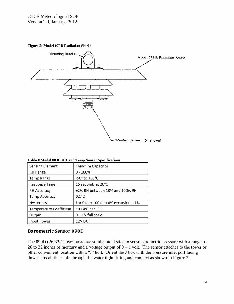
CTCR Meteorological SOP
Version 20 January 2012
9
Figure 2 Model 073B Radiation Shield
Table 8 Model 083D RH and Temp Sensor Specifications
Sensing Element Thin-film Capacitor
RH Range 0 - 100
Temp Range -50deg to +50degC
Response Time 15 seconds at 20degC
RH Accuracy plusmn2 RH between 10 and 100 RH
Temp Accuracy 01degC
Hysteresis For 0 to 100 to 0 excursion le 1
Temperature Coefficient plusmn004 per 1degC
Output 0 - 1 V full scale
Input Power 12V DC
Barometric Sensor 090D
The 090D (2632-1) uses an active solid-state device to sense barometric pressure with a range of
26 to 32 inches of mercury and a voltage output of 0 ndash 1 volt The sensor attaches to the tower or
other convenient location with a ldquoJrdquo bolt Orient the J box with the pressure inlet port facing
down Install the cable through the water tight fitting and connect as shown in Figure 2
CTCR Meteorological SOP
Version 20 January 2012
10
Figure 3 Installing the Barometric Sensor 090D Wiring
The sensor has been calibrated at the factory and will not change unless damaged No field
modification or calibrations can occur To check for proper operation compare to a local
weather station to see if the readings are reasonable The measurement will not be exactly the
same due to differences in elevation and measurement parameter absolute or normalized to sea
level This sensor measures absolute inches of mercury BP can also be checked when
conducting regular flow verifications or calibrations on the BAM 1020 The deltaCal standard
measures BP as millimeter (mm) or millibars (mb) and can be converted to inches mercury by
multiplying mm X 03937 and mb X 00295
Maintenance consists of inspecting the pressure inlet port for blockages and removing
obstructions if found If service or recalibration becomes necessary then send the sensor to the
manufacture
Rain Gauge 375 001 Inches This sensor measures precipitation on a continuous basis and is low-maintenance The tipping
bucket collects 001 inches of precipitation then tips and drains This triggers a switch closure
pulse that is counted The tipping bucket and rain gauge are heated to prevent accumulation of
snow and ice The sensor has been calibrated at the manufacture and should not require
adjustments after installation Mount the sensor level on a platform using the built in level and
three adjusting legs Follow the instruction in the operations manual (Appendix F) for complete
installation instructions A debris screen should be removed during the winter when snow will
accumulate
After installation manually actuate the tip bucket mechanism three times and confirm the tips
have registered on the data logger Inspect and clean the tipping buckets periodically and
physically tip to verify recording on the data logger If the sensor has been damaged or appears
to need calibration follow the instruction in the operations manual
Table 9 Model 375C Rainfall Sensor Specifications
Orifice 8 Inch Diameter
Calibration 01 Inches Rain per Switch Closure
Accuracy plusmn 1 at 1 to 3 inches per hour at 70 Fdeg
Switch Type Magnet and Reed
Mounting 3 Pad for 14 inch bolts
Dimensions 8 Inch Diameter
CTCR Meteorological SOP
Version 20 January 2012
11
Power Requirement 110 VAC
Weight 75 Pounds
Quality Control and Quality Assurance Quality Control (QC) and Quality Assurance measure are minimal due to the reliability and low
maintenance of the meteorological sensors employed The following table list all standards
used maintenance needed and actions If sensors exhibit characteristics outside of these
parameters the manufacturer will be contacted for instructions Records related to Meteorological
sensors will be tracked on the site log and summaries semiannually
Table 10 Meteorological Sensor Quality Control and Assurance Measures
Sensor Criteria Action
BX-596 ATBP Sensor
BP varies more than plusmn10 mm Hg from deltaCal Standard BAM 1020 Calibration Following SOP
Temperature varies more than plusmn2degC from deltaCal Standard BAM 1020 Calibration Following SOP
Sensor shield andor probe damaged Contact Met One for instructions
BX-592 Outside Temperature Sensor Volumetric Flow
Temperature varies more than plusmn2degC from deltaCal Standard BAM 1020 Calibration Following SOP
Temperature shield andor probe damaged Contact Met One for instructions
Model 505 Wind Sensor
Yearly zero test reading 00 to 01 ms wind speed
Contact Met One for instructions if greater than these readings
Yearly span test
Contact Met One for instructions if readings do not match those shown in Table 6
Heater not functioning Contact Met One for instructions
Relative HumidityTemperature
Sensor 083D
Yearly check for reasonableness Compare with local weather station
Yearly check for operation Blow on sensor and confirm RH rise
Barometric Sensor 090D Yearly inspection
Clean pressure inlet port for blockages when needed
Compare to deltaCal Standard Contact Met One for instructions if values do not compare reasonably
Rain Gauge 375 001 Inches
Yearly check for operation Manually tip bucket and confirm reading
Yearly check for level Use adjustment legs to level
Damage or bucket set screws loose
Follow instructions in operation manual for calibration
CTCR Meteorological SOP
Version 20 January 2012
12
Reference EPA Requirements for Quality Assurance Project Plans EPA QAR-5 Office of Environmental
Information Washington DC EPA240B-01003 March 2001
Guidance for Quality Assurance Project Plans EPA QAG5 Office of Environmental
Information Washington DC EPA240R-02009 December 2002
Guidance for Preparing Standard Operating Procedures (SOPs) EPA QAG-6 Office of
Environmental Information Washington DC EPA6000B-07001 April 2007
Met One Instruments Inc (2008) BAM 1020 particulate monitor operation manual Prepared by
Met One Instruments Inc Grants Pass OR BAM-1020-9800 Rev G
Standard Operating Procedure for the Continuous Measurement of Particulate Matter Monitoring
Sites Confederated Tribes of the Colville Reservation Air Quality Program August 2011
CTCR Meteorological SOP
Version 20 January 2012
13
Appendices
BX-596 ATBP SENSOR MANUAL
Met One Instruments Inc 1600 Washington Blvd Grants Pass Oregon 97526 Telephone 541-471-7111 Facsimile 541-541-7116
BX-S9G Sensor Manual - copy Copyright 2007 Met One Instruments Inc All Rights Reserved worldwide No part of this publication may be reproduced transmitted transcribed stored in a retrieval system or translated into any other language in any form without the express written permission of Met One Instruments Inc
Appendix A BX-596 ATBP Sensor Operation Manual
About this Manual
The BX-596 is an optional combination ambient temperature and barometric pressure sensor for use with the BAM-1020 particulate monitor The BX-596 sensor is a required accessory for all BAM-1020 configured to sample PM25 levels effective March 2007 The sensor provides ambient temperature and pressure data to the unit for actual (volumetric) flow control and flow statistics during the hourly sample cycle The BX-596 is only compatible with BAM-1020 firmware version 324 or later This manual describes the installation and operation of the BXshy596 sensor Refer to the BAM-1020 operation manual as needed
The BX-596-1 is an extended range version for extreme cold or high altitude environments
BX-59G TemperaturePressure Sensor Installed on a BAM-1020 Inlet Tube
Specifications
I
I I
I
I
I I
BX-59G Barometric Pressure Ambient Temperature Voltage Output o to 25 volts o to 25 volts
Range 525 to 825 mmHg -40 to +55 deg C Accuracy plusmn025 mmHg 25 C plusmn 15C above -30
10 Voltage 350 volts DC plusmn 02
BX-59G-1 Barometric Pressure Ambient Temperature i
Voltage Output o to 25 volts o to 25 volts Range 400 to 825 mmHg -50 to +50 deg C
Accuracy plusmn15 mmHg plusmn 15C full scale 10 Voltage 410 volts DC plusmn 02
BX-596-98DD Manua RevBdoc Page 1 of 4
Appendix A BX-596 ATBP Sensor Operation Manual
Installation and Setup
Ensure that the BAM-1020 is sited and installed properly per the instructions in the operation manual
During the installation process you will need to provide an access point for the BX-596 sensor cable to enter the shelter where the BAM-1020 is installed In some cases it is easiest to simply drill a 38 hole through the roof of the shelter about six inches away from the inlet tube then feed the cable through the hole and caulk around it to prevent leaks
There may be a better place to feed the cable into the shelter in some applications The BXshy902903 environmental shelters supplied by Met One have pre-formed access holes in the side to allow the sensor cable to be routed to the BAM-1020 Decide the best way to route the cable into the shelter The BX-596 comes with a standard 25-foot sensor cable Longer cables may be ordered if required
Remove the PM 10 head and PM25 cyclone from the top of the BAM inlet tube Attach the BXshy596 to the inlet tube (about 8 to 18 inches from the top) with the supplied U-bolt hardware Make sure that the sensor is level and tighten the U-bolt securely
Make sure the BAM-1020 is turned off then attach the sensor cable to the connector on the bottom of the BX-596 Route the loose end of the cable into the shelter and to the back of the BAM-1020 Coil up any excess length of cable Attach the cable to the back of the BAM as shown in the following table
I
BX596 ATBP Sensor Connections Wire Color Function BAM Terminal
Yellow A T Signal Output Channel 6 SIG BlackShield Ground Channel 6 COM Red +12 VDC Channel 6 POWER Green Auto 10 Signal 350V Channel 6 10 White BP Signal Output Channel 7 SIG
Reinstall the PM10 head and PM25 cyclone and seal around the cable hole with silicone if required
Operation
When the BAM-1020 is powered up with a BX-596 installed the unit will automatically sense the 10 voltage from the sensor and configure input channels six and seven to read and scale the outputs from the sensor Note The BX-596 sensor requires BAM-1020 firmware revision 320 or later The BX-596-1 extended range version requires BAM-1020 firmware revision 362 or later If the BAM firmware is not current enough then the BAM will not automatically identify and scale the sensor
Appendix A BX-596 ATBP Sensor Operation Manual
Turn ON the BAM-1020 and perform a calibration of the BX-596 Note The calibration is performed in the TESTgt FLOW screen which will not be available unless the FLOW TYPE is set to ACTUAL in the SETUPgt CALIBRATE screen You will need a reference standard measurement for ambient temperature and barometric pressure
MULTIPOINT FLOW CALIBRATION TARGET BAM STD
ltCALgt ~~~ 238 238 C BP 760 760 mmHg
FLOW 1 150 150 150 LPM FLOW 2 183 183 183 LPM FLOW 3 167 167 167 LPM
CAL NEXT DEFAULT EXIT
1 Enter the TESTgt FLOW menu as shown above The nozzle will lower automatically when this screen is entered The BAM colurnn is what the BAM-1020 measures for each parameter and the STO column is where you will enter the correct values from your reference standard The ltCALgt symbol will appear next to the parameter selected for calibration
2 Measure the ambient temperature with your reference standard positioned near the BXshy596 sensor Enter the value from your reference standard into the STO field using the arrow keys Press the CAL hot key to correct the BAM reading The BAM and STO values should now be the same
3 Press the NEXT hot key to move the ltCALgt indicator to the BP field and repeat the same steps for barometric pressure
The DEFAULT hot key can be pressed to reset the user calibration from the selected parameter and replace it with a factory setting The DEFAULT calibration should be fairly close in most cases
The BX-596 sensor is almost always calibrated as part of a BAM-1020 flow calibration Always calibrate the AT and BP channels before calibrating the flow channels as the flow rate is affected by the temperature and pressure of the ambient air
The 8X-596 temperature output may also be checked in an ice bath The ice bath test is usually never done except in some cold weather environments First calibrate the sensor at ambient temperature then use the following steps
1 Remove the stop screw from the bottom of the mounting bracket so that the electronics module is free to rotate Rotate the module counter-clockwise until it disengages from the keyhole slots and comes free from the radiation shield
2 The sensor comes with an 18 inch long ice bath extension harness This may be used to allow the temperature bead to reach the ice bath if necessary Carefully unplug the black temperature bead assembly from the top of the electronics module and install the harness between the bead and the module
3 Insert the temperature bead into the ice water bath along with your reference sensor Avoid immersing the bead assembly past the connector
Appendix A BX-596 ATBP Sensor Operation Manual
4 Allow the bead to equilibrate then compare the AT reading in the TESTgt FLOW screen to your reference sensor The readings should match within plusmn15 degrees C for the BXshy596-1 extended range sensor Note The tolerance for the regular BX-596 standard range sensor is plusmn 25 C in temperatures below -30C
5 Remove the ice bath harness and reassemble the sensor
During operation of the BAM-1020 the output from the BX-596 can be viewed from the main flow statistics screen or the OPERATE screens See the BAM-1020 manual
JI -~J
1 1~
i gt
-- --- shyv_
Ice Bath Extension Harness
Maintenance The BX-596 is designed to be low-maintenance easy to access and resistant to harsh environments There are only a few maintenance items for the sensor besides routine calibration checks
bull Remove the bottom cover and make sure that the four holes in the cover plate are clear and have not been obstructed by insects or debris These holes allow the air pressure to equilibrate inside the sensor for the barometric pressure reading Clean the inside of the electronics enclosure every 12 months or as needed
bull Clean the radiation shield assembly at least once per year Dirty shields reflect away solar radiation less efficiently
bull The circuit board is not intended to be removed or serviced by the customer bull The black temperature bead assembly may be replaced if the bead becomes damaged
The assembly simply plugs into the top of the electronics module The sensor will need to be recalibrated any time the temperature bead is replaced
Technical Support
Should you still require support after consulting your printed documentation we encourage you to contact one of our expert Technical Service representatives during normal business hours of 700 am to 400 pm Pacific Standard Time Monday through Friday In addition technical information and service bulletins are often posted on our website Please contact us and obtain a Return Authorization (RA) number before sending any equipment back to the factory This allows us to track and schedule service work and expedite customer service
Phone (541)471-7111 Fax (541)471-7116 E-Mail servicemetonecom Web wwwmetonecom
Mail Technical Services Department Met One Instruments Inc 1600 NW Washington Blvd Grants Pass OR 97526
Appendix A BX-596 ATBP Sensor Operation Manual
warranty
Products manufactured by Met One Instruments Inc are warranted against defects in material and workmanship for a period of one (1) year from the date of shipment from the factory Offered products not manufactured by Met One Instruments Inc will be warranted to the extent and in the manner warranted by the manufacturer of that product
Any product found to be defective during the warranty period will at the option of Met One Instruments Inc be replaced or repaired In no case shall the liability of Met One Instruments Inc exceed the purchase price of the product
This warranty may not apply to products that have been subject to misuse negligence accident acts of nature or that have been altered or modified other than by Met One Instruments Inc Consumable items such as bearings and batteries are not covered under this warranty
Other than the warranty set forth herein there shall be no other warranties whether expressed implied or statutory including warranties of fitness or merchantability
Service
Ary product being returiled to Met One Instruments In for service repair or calibration must be assigned a return authorization (RA) number Please call (541) 471-7111 or (972) 412-4715 for an RA number and shipping instructions
Products manufactured by Met One Instruments Inc that are returned for service repair or calibration are warranted against defects in material and workmanship for ninety(90) days from date of shipment under the same conditions as stated above
999
Appendix A BX-596 ATBP Sensor Operation Manual
Temperature Probe amp Shield Model BX-592
Operation Manual BX-592-9800
1600 Washington Blvd Regional Sales amp Service Grants Pass Oregon 97526 3206 Main St Suite 106
Met One Instruments
Telephone 541-471-7111 Facsimile 541-541-7116
Rowlett Texas 75088 Telephone 972-412-4715 Facsimile 972-412-4716
Appendix B BX-592 Temperature Probe and Shield Operation Manual
Model BX-592 Temperature Probe amp Shield Operation and Installation Manual
INTRODUCTION The Model BX-592 is a temperature probe and shield for use with the BAM-1020 particulate analyzer The BX-592 is used specifically with the BX-962 Volumetric Flow Control System used on the BAM-1020 This sensor provides temperature measurement of the outside air used to determine the temperature correction value as part of the volumetric flow calculation The sensor is designed to be connected directly to one of the analog input channels of the BAMshy1020 The BX-592 is used when there is no other source of analog temperature output from an existing temperature system at the owners location The BX-592 includes 30 ft of cable as well as a mounting adapter that attaches to the inlet tube of the BAM-1020
INSTALLATION The BX-592 is installed outside near the intake of the BAM-1020 particulate analyzer Mounting hardware is provided for direct mounting on the BAM-1020 inlet tube as shown in figure 10 Attach the temperature probe and shield to the horizontal bar using the clips on the top of the temperature shield Push the shield up onto the horizontal bar and press the grey plastic clips together until you hear the snap of the retainer locking inplace
The fitting on the mounting arm should be mounted in a convenient place near the top of the inlet tube and out of the way of the supports used to hold the inlet tube in place Tighten the set screws on the mounting adapter to hold it in place on the inlet tube The horizontal bar can be moved as necessary to mount the shield in a suitable location near the inlet tube and the PM-10 or PM-25 inlet assembly
The cable from the sensor can then be run down through the roof of the shelter or building so that it can be connected to the sensor input channel terminal block on the back of the BAMshy1020 unit
Figure 1 Temperature Sensor Installation
BX-592 Manual 31JAN2001 2
Appendix B BX-592 Temperature Probe and Shield Operation Manual
The sensor input connection should be made at sensor location six This input channel is the one used for any external temperature analog input used for the temperature correction input required by the volumetric flow controller
The BX-592 Temperature Sensor and Shield provides a special ider1tification output signal that is used by the BAM-1020 to determine what type of sensor is connected to the BAM as well as determine what the range of the temperature sensor The electrical connections to the BAMshy1020 can be see in Figure 2 Be sure that the color code of the individual wires of the cable is followed so that the sensor is not connected incorrectly to the BAM-1020 There are four wires which are connected to the four terminals of the analog inputs at the back of the BAM unit
IO~=== laquo) SIG ~2P-~~~WHTd COM ~~BLK ----~_4z ~ PWR ~2P-REO ----- I I 0 ~d)J-GRN --shyUL=== ~
SIG ~
Figure 2 Sensor Connections to BAM
Figure 2 shows the connections from the BX-592 Temperature Sensor and Shield to the BAMshy1020 Particulate Analyzer Be sure that the temperture sensor cable is connected to channel 6 of the BAM-1020 otherwise the voltage output of the sensor will not be able to be used as the temperature reference of the volumetric flow controler
For correct operation of the volumetric flow control option BX-961 the BAM-1020 must be programmed for volumetric flow operation This is done from the SETUP then CALIBRATE and then FLOW TYPE screen The default is metered flow and will need to be set for volumetric flow for tt1ts option to work correctly See the BAM-1020 Manual section 414 for information on the Calibrate Screen and in section 63 for information on the field calibration of the flow system
SPECIFICATIONS The following are the specifications of the BX-592 Temperature Sensor and Shield These are subject to change as determined by Met One Instruments Inc The shield of the BX-592 provides protection of the temperature probe from errors that are caused by direct solar radiation The shape allows for the wind to naturally aspirate the shield to reduce the total effect of solar radiation on the temperature measurement
Temperature Probe Type Thermistor Bead multi-element
Temperature Accuracy
Temperature Range
Sensor Output o to 1 VDC for temperature range
Time Constant 10 Seconds in still air
BX-592 Manua13IJAN2001 3
Appendix B BX-592 Temperature Probe and Shield Operation Manual
The shield is mounted from the top of the shield using two snap clamps designed for a 1 diameter tube or a IPS Pipe The mounting adapter and a short boom are provided for attachment to the inlet tube of the BAM-1020
MAINTENANCE amp CALIBRATION The temperature probe and shield require no specific maintenance other than normal cleaning of dirt and dust to prevent the degredataion of the reflectiveness of the shield If there is any build up of materials inside the shield they should be cleaned out so that there is a free path for air flow around the temperature probe
On a regular basis the output of the temperature probe displayed on the screen of the BAMshy1020 should be checked against a reference thermometer to be sure that the BX-592 is providing accurate information for the calculation of volumetric flow There are no adjustments inside the temperature probe and any repairs should be handled by the factory
Before returning a faulty probe the factory should be contacted a RA (Return Authorization) should be obtained and the problem noted on the RA This will insure that the repairs are made quickly and returned for installation
TROUBLE SHOOTING
Symptom Identify Problem Solution Incorrect Temperature indicated on BAM Display
Verify that connections to the rear panel of the BAM are correct and to channel 6
Change wiring to follow diagram as indicated in figure 2 of this manual
From setup menu channel Change settings from parameters screen verify that MANUAL Mode to Auto ID channel 6 is set for Auto ID mode for probe to work and not in MANUAL Mode correctly Examine output of BX-592 to Using a volt meter measure verify that it has the correct voltage between the black and voltage output for the current white wires 0-1 volt is ambinet temperature equivalent to -30 to 50
degrees C Le 21degC =637 volts If this is not correct return probe for repair
Volumetric Flow Control is not operating
Go to the Setup then Calibrate screen menu and verify that the flow type is set to volumetric and not metered
Default setting is for metered it will be necessary to change setting to volumetric flow type
Examine rear of BAM-1020 and see if there is a flow adjusment knob on the back of the unit right above the vacuum line
If there is a knob here it is most likely that volumetric flow control is not installed on this unit Contact Met One Instruments for advice
Volumetric flow value does not match audit flow meter connected to BAM
From setup menu select flow and examine the current measured flow value of the BAM
Recalibrate the BAM flow meter using the proceedure in the manual section 63 Field Calibration of Flow System
Verify that the audit instrument being used has been calibrated for volumetric flow monitoring
Adjust flow audit device for correct measurement of volumetric flow
BX-592 Manual 3IJAN200 1 4
Appendix B BX-592 Temperature Probe and Shield Operation Manual
For any other specific problems with the BX-592 or the Volumetric Flow Option BX-961 contact the factory
Met One Instruments Inc 1600 NW Washington Blvd Grants Pass Oregon 97527
(541) 471-7111 Voice (541 ) 471-7116 FAX
service metonecom e-mail
Visit our web page at httpwwwmetonecom
BX-592 Manual 31JAN2001 5
Appendix B BX-592 Temperature Probe and Shield Operation Manual
MODEL 505 WIND SENSOR
OPERATION MANUAL Document No 505-9800
1600 Washington Blvd Grants Pass Oregon 97526
Met One Telephone 541-471-7111 Instruments Facsimile 541-541-7116
Regional Sales amp Service 3206 Main St Suite 106 Rowlett Texas 75088 Telephone 9724124715 Facsimile 972-412-4716
505-9800 Rev Edoc
Appendix C Model 505 Wind Sensor Operation Manual
Copyright Notice
505 Sonic Wind Sensor Manual
copy Copyright 2005 Met One Instruments Inc AI Rights Reserved Worldwide No part of this publication may be reproduced transmitted transcribed stored in a retrieval system or translated into any other language in any form by any means without the express written permission of Met One Instruments Inc
Technical Support Should you require support please consult your printed documentation to resolve your problem If you are still experiencing difficulty you may contact a Technical Service representative during normal business hours-730 am to 400 pm Pacific Standard Time Monday through Friday
Voice (541) 471-7111
Fax (541) 471-7116
E-Mail servicemetonecom
Mail Technical Services Department Met One Instruments Inc 1600 Washington Boulevard Grants Pass OR 97526
505-9800 Rev E Page 2
Appendix C Model 505 Wind Sensor Operation Manual
TABLE OF CONTENTS 1 GENEAAL INFORIIATION 5
2 INSTALLATION 5
21 LTNPACKlNG 5 22 PREPARATION 5 23 SENSOR SITING 6
Figure 2-1 Siting Wind Instroments 6 24 ORIENTATION WITH FIXTURE 7
Figure 2-2 Orientation Fixture 7 25 ORIENTATION WITHOUT FIXTURE (SEE FIGURE 2-3 AND 2-4) 8 26 EXTERNAL HEATER 8
Figure 2-3 505 Wind Sensor Components 9 Figure 2-4 Alignment aSensor to Troe North 10
27 INSTALLATION OF AVERY DETERRENTS 11 Figure 2-5 InstallatIOn ofAviary Delerrents I
28 CONNECTIONS TO RECORDING ELECfRONICS 12
Figure 2-7 Factory Standard Analog amp Rf-232 Output Connections (Cable 9574 wi Differential Amplifier
Figure 2-8 Factory Custom SDI-12 Output Connections 3
Figure 2-6 Amplifier (9573) attached to Cable (9574) and wiring in box 12
9573) 12
Figure 2-9 Factory Custom RS4221485 Output Connections 13 28 SIGNAL OUTPUTS ANALOG RS-232 ANDSDI-12 13 29 SIGNAL OUTPUTS - RS422 AND RS485 14
3 OPERATIONAL CHECK-OUT AND CALmRATION 14
31 GENERM 14 32 RECORDING ELECTRONICS 14 33 ZERO TEST 14 34 SPAN TEST 14
4 MAINTENANCE AND TROlTBLESHOOTING 15
41 GENERAL MAlNTENANCE SCHEDULE 15 42 TROlTBfJESHOOTING 15
5 TIIEORY OF OPEAATION 16
51 SPEED OF SOUND IN AlR 16 52 SPEED OF S()UND PRINCIPLE 16 53 CALCULATION OF THE WIND VELOCITy 16
6 SPECIFICATIONS 17
FIGURE 6- 505 Wind Sensor Outline Dimensions 18
APPENDIX A - WIND DIRECTION SENSOR ORIENTATION 19
APPENDIX B - WIND SENSOR MOUNTING OPTIONS 22
APPENDIX C - HEATER CONFIGURATION AND WIRING 23
APPENDIX D - RS2J2 COMMAND SET 25
GENERAL PROTOCOL 25
1 RS-2J2 DATA OUTPUT PROTOCOL 25
11 ERROR CODE 26
2 USER COMMAND SET _ 27
21 L8-VERBOSE CONTROL OF RS-232 PARAMETER LABELS 27
505-9800 Rev E Page 3
Appendix C Model 505 Wind Sensor Operation Manual
22 MS-MAxLMUM FULL SCALE WIND SPEED 27 23 SU-WINO SPEED UNITS 27 24 QU-QUlT 27 25 SB-SERIAL BAUD RATE 28 26 ST-SERIAL TRIGGER (RS-485 ONLy) 28 27 IT-SONIC TEMPERATURE 28 28 VN-VERSION NUMBER 28 29 VS-FULL SCALE ANALOG OUTPUT VOLTAGE FOR WINO SPEED Ai~O WINO DIRECTION 28
505-9800 Rev E Page 4
Appendix C Model 505 Wind Sensor Operation Manual
MODEL 505 WIND SENSOR OPERATION MANUAL
1 GENERAL INFORMATION
The Met One Instruments Model 505 Wind Sensor is a solid-state ultrasonic instrument capable of measuring wind speed and wind direction in the U and V axes Sonic pulses are generated at the transducers and are received by opposing transducers Mathematics derived for these sonic pulses provide a wind velocity measurement in each of the corresponding axes
The 505 uses a microprocessor-based digital electronic measurement system to control the sample rate and compute the wind speed and wind direction The sensor is factory calibrated and requires no field calibration In the field the operation of the sensor can be quickly checked using a combination of simple tests A zero chamber or bag is used to verify the zero reference by covering the entire sensor or individual outputs are checked by blocking various combinations of sensors
The 505 provides are variety of outputs to suit the connection requirements of the user Standard outputs are voltage and RS-232 SDI-12 and RS422485 outputs are configured at the factory
2 INSTALLATION
21 UNPACKING
Carefully remove the sensor from its shipping container and inspect it for damage Referring to the packing list check for shortages Any claims for damages should be filed promptly with the carrier
The sensor is a precision electromechanical transducer Always handle it with care exercising particular caution to ensure that the instrument is not subjected to side loading shock or other abuse After initial inspection keep the sensor in its shipping container for protection until actual installation
22 PREPARATION
For accurate measurements the sensor mount must be rigid with little or no movement from the wind The sensor is designed for installation in a Model 3188 mounting and alignment fixture This provides a mount for use on a horizontal IPS pipe (105- 00) boom Mounting information and diagrams can be found in Appendix B of this manual
The 3188 Sensor Mounting Fixture includes a keyed bushing which will be adjusted for alignment to North orientation This enables the sensor to be removed and replaced without requiring realignment Three captive machine screws are used to secure the sensor to the keyed bushing
If a temperature shield such as the Model 0738 is to be used in the configuration the Model 1539-4 Arm and 1552 Mount is recommended These parts provide the necessary mounting for a vertical mast of 0 IPS pipe (105 OD) This same configuration can also be used to mount other sensors as well as providing a way to mount the sensor on a vertical mast (See Appendix B for Mounting Details)
505-9800 Rev E Page 5
Appendix C Model 505 Wind Sensor Operation Manual
23 SENSOR SITING
The primary objective of instrument siting is to place the instrument in a location where it can make precise measurements that are representative of the general state of the atmosphere in that area Because most atmospheric properties change dramatically with height and surroundings certain somewhat arbitrary conventions must be observed so that measurements can be compared
lOT
Figure 2-1 Siting Wind Instruments
The standard exposure of wind instruments over level open terrain is 10 meters above the ground (WMO 1971) however optimum measurement height may vary according to data needs Open terrain is defined as an area where the horizontal distance between the wind sensor and any obstruction is at least ten (10) times the height of that obstruction An obstruction may be man-made (such as a building) or natural (such as a tree) (See Figure 2-1)
The wind instrument should be securely mounted on a mast that will not twist rotate or sway If it is necessary to mount the wind instrument on the roof of a building it should be mounted high enough to be out of the area in which the airflow is disturbed by the building This is usually 15 times the height of the building above the roof so that it is out of the wake of the obstruction This is not a good practice however and should only be resorted to when absolutely necessary
Wind instruments are best sited when they are used on towers The tower should be located in an open level area representative of the area under study Towers should be of the open grid type of construction such as is typical of most television and radio broadcast towers Enclosed towers stacks water storage tanks grain elevators cooling towers and similar structures should not be used
Wind instruments should be mounted above the top of the tower on booms projecting horizontally out from the tower If a boom is used it should support the sensor at a distance equal to minimum of twice or at best three times the maximum diameter or diagonal of the tower away from the nearest point on the tower On large towers with large verticals it may be best to place the sensor at least 5 tower leg diameters from the tower leg The boom should project into the direction which provides the least distortion for the most important wind direction For example a boom mounted to the east of the tower will provide least distortion for north or south winds
505-9800 Rev E PageS
Appendix C Model 505 Wind Sensor Operation Manual
Weather sensors are sensitive to direct or nearby lightning strikes A well-grounded metal rod or frame should be placed above the sensor installation In addition the shield on the signal cable leading to the translator must be connected to a good earth ground at the translator end and the cable route should not be vulnerable to lightning
24 ORIENTATION WITH FIXTURE
The Orientation Fixture Model 705 is used for very accurate positioning of the 505 sensor with respect to a benchmark or other object that can be visually obselVed If a compass is used to establish a benchmark the reading should be taken away from heavy metal objects which can affect the reading and should be corrected for declination of the magnetic north pole The benchmark is set to true north of the sensor site Information on determining true North can be found in Appendix A of this manual
The fixture contains a telescopic sight with crosshairs and includes a keyed base identical to that on the sensor The fixture is specifically designed for use with the 3188 Sensor Mounting Fixture The base of the fixture is keyed so that the object lens of the sight assumes the same position as the north side of the sensor
Before orienting the sensor ensure that it is vertical and adjust the cross arm as necessary Orientation of the sensor is then performed with the fixture installed on the cross arm in place of the sensor (The three screws in the base of the fixture must be tightened to ensure proper orientation in the cross arm) Loosening the three setscrews on the side of the sensor mount allows free rotation of the keyed bushing and orientation fixture The ring and fixture are then rotated to position the benchmark in the center of the sight crosshairs The sight can be tilted as necessary by loosening the slotted screw on the side of the fixture The set screws are then tightened the fixture removed and the sensor installed in its place The sensor is now oriented for zero (north) wind direction signal output when the wind is from north
OSIECTlENS
Figure 2 2 Orientation Fixture
The electrical connector on the bottom of the sensor should be properly mated to the cable connector and the three captive screws on the base of the sensor should be tightened
When using the orientation fixture assure that the two-piece mounting assembly is properly aligned The upper half of the assembly contains a horizontal peg which must seat in the vshynotch located in the lower half The knurled knob on the lower half is used to secure the two sections and should be tight
505-9800 Rev E Page 7
Appendix C Model 505 Wind Sensor Operation Manual
25 ORIENTATION WITHOUT FIXTURE (See FIGURE 2-3 and 2-4)
Establish a True North benchmark See Appendix A for aids to determine True North This should be a point directly north from the sensors mounted location This point should allow easy access so that a person may sight the sensor with a spotting telescope If a compass is used to establish a benchmark the reading should be taken away from heavy metal objects which can affect the reading and should be corrected for declination of the magnetic north pole The benchmark is set due north of the sensor site
One person is located at True North benchmark equipped with a spotting scope A second person is located at the sensor The sensor alignment may be established as follows
A Install the sensor into the alignment bushing and secure with the two setscrews under the 3188 Alignment Fixture Keep the three setscrews around the ring of the fixture loose so that the ring can be rotated into position
B Turn the sensor so that the sensor paints to the North benchmark Tighten the 3 setscrews and recheck align ment
C Connect the 9574-cable assembly to the sensor Secure cable to boom with cable ties or tape to prevent damage
D The sensor can be removed without requiring realignment at any time Simply remove the sensor The alignment bushing remains proper1y oriented in the fitting
26 EXTERNAL HEATER
The Optional External Heater provides de-icing for the sensor arms and prevents the accumulation of ice which might block the sonic sensor elements The heater consists of a laminated heater material that is custom designed and wrapped around the four sensor arms and sonic sensor element housings The heater controller requires 15 to 24 VACNDC at approximately 4-5 amps at startup There are jumper connections on the controller board for the selection of power source The controller is normally provided with the jumpers not installed This is for 24 volts AC operation of the heaters Heater power can be supplied from a power transformer or a Met One Instruments supplied power unit in a weatherproof box The proportional controlled heater uses maximum current at start-up and power requirement goes down as the sensorheater reaches stability The heater is activated at 38 degrees F and will keep the arms ice-free at temperatures down to below -20 degrees F The connection information can be found in Appendix C of this manual
The temperature controller electronics box should be mounted no more than 5 feet from the sensor using the cable supplied with the heater controller The power cable should be of minimum 16 AWG wire and cable length should be at a minimum to prevent power loss due to cable resistance at the 4-amp power requirement
505-9800 Rev E Page 8
Appendix C Model 505 Wind Sensor Operation Manual
MODEL 505 WINO SENSOR
NORTH SCREWPIN ____~~--
THIS SIDE TO FACE SOlTTH LABEL
NORTH SLOT HOLE~middot-c-lIIo-
SET SCREWS (3 EA FOR SECURING
KEYED BUSHING TO HORTH ORIENTATION
(7164- ALLEN KEY)
Figure 2-3 505 Wind Sensor Components
Page 9 505-9800 Rev E
Appendix C Model 505 Wind Sensor Operation Manual
SOUTHSIDE SENSOR TRANSDUCER SHOULD BE SEEN EaUALLY DIVIDED
BY NORTHSIDE (NEAR) ARM
Figure 2-4 Alignment of Sensor to True North
505-9800 Rev E Page 10
Appendix C Model 505 Wind Sensor Operation Manual
27 INSTALLATION OF AVERY DETERRENTS
To prevent birds from entering the pathway between the sensors a vertical stainless steel rod is located in the center of the sensor array_ To keep birds from perching on the sensors stainless steel wire aviary deterrent need to be installed on the sensor prior to installation in the fixture
NOTE The stainless steel wires used for the aviary deterrents are very sharp The wire is spring steel and there s the possibility that it could slip off during the installation Use care
when installing the aviary deterrent and be careful after installation
PROTECTIVE GLASSES SHOULD BE WORN DURING INSTALLATION
Installed A viarv Deterrents
area
AVIARY DETERRENTS bull PIIIih ends IowaIds eoch ltlttler lil qgten up
spring d1amccr bull Slide owr lranllducer 10 mounIing llIII bull ~6l as requRd 60 that avlary
delemK1N are pointed ~
MOUNTING AREA
Figure 2-5 Installation of Aviary Deterrents
WARNING If the aviary deterrents are not properly installed The sensor may experience signal degradation Install as shown DO NOT allow for the spring section of the aviary deterrent to contact the transducer portion of the sensor array_
505-9800 Rev E Page 11
Appendix C Model 505 Wind Sensor Operation Manual
28 CONNECTIONS TO RECORDING ELECTRONICS
Route the cable to the data-recording device Secure the cable with cable ties or tape The 9574shycable assembly contains 7 wires and a shield Typical wiring hookup is shown in the figures below Actual wiring will depend upon the version of the sensor To determine which of the three connections drawings apply examine the cable part number at both ends of the cable
Cable type 9574 includes the 9573 Differential Amptifier it is located at the end of the cable opposite the sensor connector The amplifier provides high immunity to any noise that might be picked up the sensor cables It is recommended that this cable with amplifier be used whenever connected to a single ended input recorder If necessary to remove the differential amplifier a wiring diagram has been included in the top of the small amplifier enclosure A small screwdriver is provided for use on the small terminal screws on the PC Board of the 9573 Amplifier Be sure that the connection color codes are followed so that no wiring error occurs See below
Warning If you are connecting this 505 to an older 3155-cable assembly and are using the black wire as signal common disconnect it because it will short out the RS-232 transmitter No damage will occur to the circuit but the 505 current consumption will increase by 20 rnA
TO SONIC
~ n 0 SHLD (WTIBN) +12Y(Wiri) 0 0 NIC wo oOt-(RpoundD 0 0 GND(GRN) WD 0lIT~ (OAN) 0 0 ncD(8LK) W8 ~+(BLU) 0 0 RXC(IRN) NC 0 0 WSIN+(BW) RXD(8fCN) 0 0 NIC TXDl8LJC) 0 0 WDW+(RED) OND(GRN) 0 0 WDIN-(ORN) NIC Omiddot 0 +12V(WtfT) SHLD (WTIBN) 0 J1 r-
TO DATALOGGIR
Figure 2-6 Amplifier (9573) attached to Cable (9674) and wiring in box
Sensor Common
Power Common WHITE
RED
+12V Power
BROWN RXRS-232 BLACK TXRS-232
Wind Direction Voltage BLUE OR YELLOW Wind Speed Voltag~
Shield WHITEBROWN
Figure 2-7 Factory Standard Analog amp RS-232 Output Connections (Cable 9574 wI Differential Amplifier 9573)
505-9800 Rev E Page 12
Appendix C Model 505 Wind Sensor Operation Manual
o NG[ GREEN WHITE
BROWN
aLACK
REO
BLUE OR YEllOW
Sensor Common
Power Common
+12VPower
Not Used
Not Used
Not Used SOI-12 Output
Shield WHITEBROWN
Figure 2middot8 Factory Custom SDI~12 Output Connections
ORANGE
RED
Sensor Common GREEN Power Common WHITE +12V Power
BROWN RX f
BLACK RX shy
TX+ BLUE OR YELLOW TX-
Shield WHITEBROWN
Figure 2-9 Factory Custom RS4221485 Output Connections
28 SIGNAL OUTPUTS - AnalogJ RS-232 and 501-12
The standard configuration of the sensor provides for a voltage outputs for wind speed and direction as well as RS-232 Data The default output voltage is 10 volts full scale for 50 meterssecond and 360 degrees of direction Alternate full-scale values can be changed by using the RS-232 command set discussed in Appendix O The R8-232 output occurs every second in the format S sssS 0 ddd ltcrgtltIfgt where ssss is the wind speed value up to 9999 and the direction ddd up to a value of 360 RS-232 output is at 9600 baud 8 data bits 1 stop bit and no parity
As an option an output of 801-12 Data from the sensor is available In this configuration it is the only available output and is in the format +ssss+ddd ltcrgtltlfgt The same values for sssS and ddd as the RS-232 format are output The 801-12 handshake is per the 801-12 specifications and format In this configuration the RS-232 output or analog output is no longer available from the sensor
505-9800 Rev E Page 13
Appendix C Model 505 Wind Sensor Operation Manual
29 SIGNAL OUTPUTS - RS422 and RS485
In this configuration the sensor has no analog outputs (see diagram Factory Custom RS422RS485 Output Connections The correct sensor cable for this configuration is part number 3379
The default serial trigger (sensor address) is 1 After receiving 1 the sensor will return wind speed and wind direction in the same format as with RS232 (S sSSs D ddd ltcrgtltlfraquo
To use the RS232 Command Set defined in Appendix 0 the sensor must first be put into Terminal Mode by sending (three exclamation points) The serial trigger is not used in this case and there must be only one sensor connected on the serial buss The sensor will return when in Terminal Mode and will then accept RS232 commands The au (quit) command will take the sensor out of Terminal Mode and return it to normal operating mode
3 OPERATIONAL CHECK-OUT AND CALIBRATION
31 GENERAL
Operation of the 50S is essentially automatic and no specific sensor calibration is required for normal operation The sensor has been calibrated in a wind tunnel at the factory prior to shipment
32 RECORDING ELECTRONICS
The sensor may be connected to a variety of data recorders and translators Standard wind speed range is O-SO mls and wind direction range is 0-360 degrees Standard output voltage is 0-10V with 0-2SV and O-SOV as available options Refer to the calibration certificate supplied with the sensor to determine the actual output
To ensure that the recorder is scaled properly it is recommended that zero and span tests are performed after the sensor is connected and operational
33 ZERO TEST
A zero test requires no air movement across the sensor array so a means of covering the array is needed A plastic bag can be placed over the array using care not to contact the transducers or block the sonic paths between transducers The bag should be spaced at least 2 above the transducers to avoid sonic reflections which may affect readings The bag can be tied at the bottom with a tie wrap or tape to prevent air movement from below Keep in mind that wind can defrect the bag causing air movement inside
The preferred method is to use a box insulated with foam to prevent reflections and spaced so that the top is at Jeast 2 above the transducers Again the bottom should be sealed around the sensor to isolate the array from ambient air movement
With no air movement across the array the sensor should indicate 00 to 01 ms wind speed The wind direction output will wander to any value between 0 and 360 degrees
34 SPAN TEST
The sensor is designed to produce known default outputs if an object blocks the sonic signal path between the transducers This feature is useful for verifying sensor operation and recorder scaling For testing purposes the sonic path can be blocked by placing a finger (or any solid object) on the face of one or more transducers
505-9800 Rev E Page 14
Appendix C Model 505 Wind Sensor Operation Manual
NOTE The following table defines the sensor outputs with blocked paths
Wind Speed Blocked Axis Serial Output North-South 100 mls East-West 100 mls 80th 100 mls
Analog Out~ut 50 mls 50 mls 50 mls
D-10V 100V 100V 100V
0-2SV 250V 250V 2S0V
O-SOV 500V SOOV SOOV
Wind Direction Blocked Axis Serial Output Analog Output D-10V 0-25V D-50V North-South 10 Deg 10 Deg 003V 007V 014V East-West 160 Deg 160 Deg O44V 111V 222V Both 170 Deg 1700eg 047V 118V 236V
4 MAINTENANCE AND TROUBLESHOOTING
The 50S sensor is sealed and there are no replaceable parts contained therein The sensor does not require periodic calibration and there are no internal adjustments that can be made
41 GENERAL MAINTENANCE SCHEDULE
12-24 month intervals
The Model 505 Wind Sensor should be inspected periodically for physical damage to the sensor array assembly cable and cable connections Inspect all transducers to be sure they are securely fastened
Schedule based on average to adverse conditions
42 TROUBLESHOOTING ------ --shy--=-----------------==-----~~---- ----~-~-~~~~~~---~-----~ ----~~~~~~~--
~________~piom _~ __ ____ _____ ~~o~babl~9_C1l1~~_~___ ~__+_-_-A-ct-io-n-to-R-eL-pa_ir__---i
Wind Speed output goes to full Blocked pathway 1 - Check path and clear scale
Failed sensor 2 - If clear contact factory for Return Authorization to repair sensor
Wind Speed output high but not Common mode voltage 1 - Replace cable with part full scale number 9574 (with 9573
differential-to- single-ended converter)
supply 2 - Use 3379 cable and power sensor with isolated power separate from recorder power supply
inputs 3 - Use 3379 cable and connect sensor signals to differential on recorder
505-9800 Rev E Page 15
Appendix C Model 505 Wind Sensor Operation Manual
5 THEORY OF OPERATION
51 SPEED OF SOUND IN AIR
The speed of sound in still air can be measured accurately between two points a few centimeters apart by two ultrasonic transducers set at that distance The resulting speed of sound is a known function of the air temperature and composition
The speed of sound waves in an ideal gas may be written
where R is the universal gas constant (083134 mJmol K) T is the temperature in Kelvin M is the molecular weight (gramsmol) of the gas and L is the ratio of heat capacities Cp and Gy Cp
and Cyare the specific heats at constant pressure and constant volume of the gas respectively
52 SPEED OF SOUND PRINCIPLE
The transit time of a sound signal traveling from one end of a sound path to the other separated by distance d can be written as follows (Schotand 1955)
where V is the total velocity Vdand Vnare velocity components in the directions parallel and normal to the sound path and C is the velocity of sound in still air If two transit times t1 and t2 in opposite directions on the same path are directed Vd can be obtained independent from V and Vn as follows
It is this principle that is used to compute the velocity of the air in the path between two opposing transducers
53 CALCULATION OF THE WIND VELOCITY
In still air t1 and t2 are equal For a distance 15 cm at 20deg C the transit time is approximately 450 IJs If a 20 mls wind is in the direction of the sonic pulse the transit time t1 will be approximately 427 IJs If the wind is opposing the sonic pulse the transit time will be approximately 482 IJs If these two values are used in the previous equation the resultant velocity from equation will be 20 ms
505-9800 Rev E Page 16
Appendix C Model 505 Wind Sensor Operation Manual
6 SPECIFICATIONS
Sonic Wind Sensor Model 606
Wind Speed Range Accuracy Resolution
Wind Direction Range Accuracy Resolution
Operation Sample Rate Data Output Rate Sonic frequency
Output Signals Wind speed voltage Wind direction voltage RS-232
Optional Digita) Outputs
Power requirement Sensor
External Heater Option
Environmental Maximum Measurement range Operating Temperature Extended Temperature Range
Physical Weight Dimensions
Options Signal Cable Horizontal Mount amp Orientation Fixture External Heater with Control Box External Heater Power Source Programming Cable amp Power Supply
oto 50 msec plusmn 02 rnIsec 113 msec or plusmn 2 gt- 113 msec 01 msec
5 per second 1 per second 200 KHz
0- 50 VDC (Specified at time of purchase) 0- 50 VDC (Specified at time of purchase) 1200 to 192K Baud
501-12 RS-422 or RS-485 (Specified at time of purchase)
9-18 VDC 10 mA 12 VDC Average power requires 75 amp pulse for 2msec
15 VDC 50 Watts
oto 65 mls -40degC to +55degC no ice -SOdegC to +55degC with external heater
S5 Ibs (25 Kg) 1929in (490mm) high 938in (238mm) diameter
PN 9S74 - Specify length PN 3188 SO5H 50SPS (100 to 240 VAC SO60 HZ) 1SVDC 4 amps TBD
Heater Options must be specified at time of purchase middotSpecifications Subject to Change without prior Notice
50S-9800 Rev E Page 17
Appendix C Model 505 Wind Sensor Operation Manual
LLJ-oIIIo----IOODfA
--20001t
FIGURE 6-1 505 Wind Sensor Outline Dimensions
505-9800 Rev E Page 18
Appendix C Model 505 Wind Sensor Operation Manual
APPENDIX A - WIND DIRECTION SENSOR ORIENTATION
INTRODUCTION Determining True North or Magnetic Declination is very important to the proper setup and orientation of the wind direction portion of the sonic wind sensor The declination value is used to determine the difference between True North and magnetic North This value varies around the world depending upon your location The following procedure can be used to either point the sonic wind sensor to True North
ADJUSTMENT Orientation of the wind direction sensor is done after the location of True North has been determined True North is usually found by reading a magnetic compass and applying the correction for magnetic declination where magnetic declination is the number of degrees between True North and Magnetic North Magnetic declination for a specific site can be obtained from a USGS topographic map pilots maps local airport or through a computer service offered by the USGS called GEOMAG
The following map showing magnetic declination for the contiguous United States is shown in the figure 1 can be used for determination of declination Tilis will depend upon the accuracy requirement required Alternately use a more accurate method of detemlining declination from magnetic North
Subtract declination from 3600 Add declination to 0deg 20W
Figure 1 typical declination values in the USA
Declination angles east of True North are considered negative and are subtracted from 0 or (360) degrees to get True North as shown in figure 2 Declination angles west of True North are considered positive and are added to 0 degrees to get True North as shown in figure 3 For example the declination for Grants Pass Oregon is 17deg East True North is 3600 -17deg or 3430 as read on a compass
505-9800 Rev E Page 19
Appendix C Model 505 Wind Sensor Operation Manual
Alignment to North Orientation is most easily done with two people one to aim and adjust the sensor while the other observes the wind direction display (Once True North is located the South reference can be determined)
1 Establish a reference point on the horizon for True North Sighting down the instrument centerline aim the two arms of the NorthSouth pair at True North with the locking set screw pointed South
2 Align the sensor adapter or adapter mount Loosen the setscrews that secure the base of the sensor to the cross arm While viewing the positionrotation of the Nortl1South sensor arms slowly rotate the sensor base until the two arms point to True North that was determined by earlier measurement using compass
Other methods employ observations using the North Star or the sun and are discussed in the Quality Assurance Handbook for Air Pollution Measurement Systems Volume IV Meteorological Measurements
Determining Local Magnetic Declination Several resources for determining the magnetic declination of any site in the world can be found on the internet or can be accessed by modem using any common terminal program
GEOMAG is a resource that can be accessed by telephone or the Internet (Telnet) connection GEOMAG is accessed by calling 1-800-358-2663 with a computer and telephone modem and communications program such as HyperTerminal GEOMAG can also be accessed by the internet using the address telnetllneiscrusgsgov
GEOMAG prompts the caller for site latitude longitude and elevation which it uses to determine the magnetic declination and annual change The follOWing Menu and prompts are from GEOMAG Use the username QED
MAIN MENU NeecJe POInfS toType Q for Quick Epicenter Determinations (QED) Magnetic North
L for Earthquake Lists (EaUST) M for Geomagnetic Field Values (GEOMAG) X to log out
Enter program option M
Would you like information on how to run GEOMAG (YN) N
FIGURE 2 Declination Angles East ofOptions True North Are Subtracted from 0 to Get True North 1 = Field Values(D I HXZ F)
2 =Magnetic Pole Positions 3 Dipole Axis and Magnitude 4 Magnetic Center
Display values twice [N] press return Name of field model [USCON951 press return Date [Current date] press return Latitude 4225 N Longitude 12320 W Elevation 1000 Units (mkmft) ft
FIGURE 3 Declinatiof1 Angles West of True North Are Added to 0 to Get True North
505-9800 Rev E Page 20
Appendix C Model 505 Wind Sensor Operation Manual
Example of report generated by GEOMAG Model USCON95 Latitude 4225 N Date 211399 Longitude 123120 W Elevation 1000000 ft
D I H X Y Z F deg min deg min nT nT nT nT nT
17 175 65 73 22056 21059 6555 47560 52425 Annual change 0 -24 0 -17 -29 18 -156 -662 -613
The calculated dedi nation would be 17 degrees and 175 minutes for Grants Pass Oregon The declination in the example above is listed as 17 degrees and 175 minutes Expressed in degrees this would be 173 degrees As shown in Figure 1 the declination for Oregon is east so True North for this site is 360 - 173 or 3427 degrees The annual change is -24 minutes In this case a value 343 degrees would probably be sufficient for most measurement accuracy
An alternative method is to find a USGS map and examine the text at the bottom center of the map At this point either a written indication is given or a symbol similar to the one seen below will be found This would indicate a declination of 15 degrees West-showing MN (magnetic North) to True North (Star) Other sources such as the local airport can be helpful in determining the correct declination
1D23 25 MilS
UTM GR-O AND 1971 MAGNETIC NORTH OECLINATION AT CENTER OF SHEET
505-9800 Rev E Page 21
Appendix C Model 505 Wind Sensor Operation Manual
r=======~ -C_ARM-c-r--r-___-r
193 MOUNTING BOOM
APPENDIX B - WIND SENSOR MOUNTING OPTIONS
TYPICAL VERTICAL MOUNTING WITH 191-6 CROSS ARM
3168 AtlGINT FlXTmE
TOP OF TOWER
TYPICAL HORIZONTAL MOUNnNG
3188 AlIGN1NT FIXTLRE
-34 IfICH PS PIPE OR II~CH DlA flO(J1
505-9800 Rev E Page 22
Appendix C Model 505 Wind Sensor Operation Manual
APPENDIX C - HEATER CONFIGURATION AND WIRING
5VJ H HEAT R HH~ING lJc_ r1
5fl5 WllO SENSOR WITH HEA TER ARRAY
3379 SIGNAL CADLE
I ALIGNMENT OASE MClJEL 3100 TEt-PERATURE
CONTROLLER
reg
505PS POWER SUPPL Y lJNIT NORMAL POWER INPUT
Fm HEATER bull bullVCLTS AC OR
TO SEIfJC)R j
HEATER UNIT
~ ro 2rJ0 VAC POWER
505-9800 Rev E Page 23
Appendix C Model 505 Wind Sensor Operation Manual
00
01 o yco o o 0 OPTIONAL ~ 505 PS SONIC WIND SENSOR m HEATER POWER SUPPLY
MOUNTl NG ON VERTICAL r PE~ 2-114 DIAMETEr-deg
---1__(I I rlif 1~I
AC POWER CORD S LONG
1201240 VAC POWER AT 14 AMPS INPUT OUTPUT 15 VDC AT 4 AMPS
U w
CO (J)
~
WEATHERPROOF ENCL
~ SONIC SENSOR - 5FT LONG ~
CUT AS NECESSARY 25 FT LONG auPPUED
2 CONDUCTOR 16 AWG CABLE BETWEEN POWER SUPPLY amp CONTROL BOX
HEATER CONTROL UNIT PART 3254 FOR SONIC WIND SENSORS
(SUPPLIED WITH HEATED SENSOR)
U08oa T FOR MOUNllNG ON VERLPIPE 314 TO z14 DIAMETER
---3871 [E-23Jrl J i II
CI In I In
WEATHERPROOF INCshy
POW UNSOR CABUi TO J
FOR USE WITH SONIC WIND SENSORS SOSHAND 03SAoH
I
Appendix C Model 505 Wind Sensor Operation Manual
APPENDIX D - RS232 Command Set
General Protocol
The computer interface commands use a simple ASCII packet protocol Only one command is transferred per packet
To enter the command mode send the exclamation point () character until the unit returns If
The unit will remain in the command mode until the quit command (QU) is received or a power reset
Command packets are constructed with a two (2) character command and if required a data string
All commands must end with a carriage return (OxOD)
The unit will echo back the command string terminated with a carriage return and line feed (OxOA)
Data string requirements are described with each command
A command with no argument returns the current setting
The default R5-232 configuration is 96008 N 1
There are two command sets-User and Factory
1 RS232 Data Output Protocol
The typical RS-232 data output stream has the following format
S ssss D dddltcrgtltlfgt
Where ssss is the wind speed value and ddd is the wind direction value The range of the direction value is 0 to 359 degrees
The units of ssss are determined by the SU (Speed Units) settings
The data output rate is determined by the TS (Sample Period) settings
Parameter labels can be suppressed by the LB setting The output format follows
ssss dddltcrgtltlfgt
The sonic temperature reading can be added to the data output with the TT (Sonic Temperature) setting The output format follows
S sSSs D ddd T ttttltcrgtltlfgt
The units of ttlt are in degrees C
The sonic error code can be added to the data output with the EE (Sonic Error Code) setting The output form follows
s sSSs D ddd T ttU E eeeltcrgtltlfgt
505-9800 Rev E Page 25
Appendix C Model 505 Wind Sensor Operation Manual
11 Error Code There is a time-of-flight window establish to determine sensor failures If the receive signal arrives before the window it is considered early If is arrives after the window it is considered late There is an early and late error code for each sensor
The firing order is NWSE so the receive order is SENW The error code table follows
Early Late
N 1 2
S 4 8
W 16 32
E 64 128
The error code output is the sum of the sensor failures An error code does not mean the speed or direction values are invalid Here is an example
S 34 D 77 E 16ltcrgtltlfgt
The speed or direction values are invalid when an axis failure has occurred for three (3) consecutive sample periods
An axis failure is when each sensor of the sensor pair has a failure-early or late When this condition occurs the speed is set to an equivalent of 1000 meter-per-second The actual speed report is determined by the SU setting The direction is equal to the error code
For example if the north-south axis is block and SU is MPS the data output looks like this
S 1000 0 10 E 10ltcrgtltlfgt
If the east-west axis is block and SU is MPH the data output looks like this
S 2237 D 160 E 160ltcrgtltlfgt
If the north-south and east-west axis is block and SU is KPH the data output looks like this
S 3600 D 170 E 170ltcrgtltlfgt
505-9800 Rev E Page 26
Appendix C Model 505 Wind Sensor Operation Manual
- -- --
2 User Command Set
Note ltcrgt refers to a carriage return
21 LB-Verbose Control of RS-232 PARAMETER labels
Display or suppress parameter labels of Wind Speed (S) Wind Direction (D) Sonic Temperature (T) and Error Code (E) at RS-232 output
COMMAND RESULT LBltcrgt Report Present Setting LBOltcrgt Suppress parameter labels LB1ltcrgt Display parameter labels
22 MS-Maximum Full Scale Wind Speed
Set the units full-scale Wind Speed output for full-scale analog output Note that these numbers MUST correspond to units set in SU below
Example COMMAND RESULT MSltcrgt Report Present Setting
-----~~
MS50ltcrgt 50 Meters per second when SU = 0 ~----- --~ -~---
MS11185ltcrgt -~~
11185 MPH when SU = 1---__--shy-MS1800ltcrgt 180 KPH when SU = 2 MS9719ltcrgt 9719 KNOTS when SU = 4
- ------- ~---
23 SU-Wind Speed Units
Set units for Wind Speed
COMMAND ULT SUltcrgt Re ort Present Units selected ------------ --middot---------+--M--P-S=-------------~----ISUOltcrgt SU1ltcrgt MPH SU2ltcrgt KPH SU4ltcrgt Knots
These values are mutually exclusive
24 QU-Quit
Exit the command mode and save any changes
COMMAND QUltcrgt Note This command not supported by SDI-12
505-9800 Rev E Page 27
Appendix C Model 505 Wind Sensor Operation Manual
25 SB-Serial Baud Rate
Read or Set the units Baud rate Note This command is not supported by SOI-12
SB2ltcrgt Set 2400 BAUD S83ltcrgt Set 4800 BAUD SB4ltcrgt Set 9600 BAUD SB5ltcrgt Set 19200 BAUD
Baud rate changes take effect after turning off the power to the sensor and turning it back on again
26 ST -Serial Trigger (RS-485 Only)
Set the string used in RS-485 mode to serve as a trigger for the units send data command
COMMAND STxltcrgt Where x can be any set of one to six alphanumeric characters except three in a row
27 TT-Sonic Temperature
Enable or disable Sonic Temperature RS-232 output
COMMAND RESULT TTltcrgt Report Present Output Status TTOltcrgt Disable Sonic Temperature Output TT1ltcrgt Enable Sonic Temperature Output
28 VN-Version Number
Returns the Firmware version number
COMMAND VNltcrgt Example Report 3194-02 R26o
29 VS-Full Scale Analog Output Voltage for Wind Speed and Wind Direction
Set the full-scale analog output voltage for the full-scale wind speed and wind direction
COMMAND V5xxltcrgt Where xx is the full-scale analog output voltage at the full-scale wind speed and wind direction
The range ofxx is 00 to 50 volts at the full scale
505-9800 Rev E Page 28
Appendix C Model 505 Wind Sensor Operation Manual
Warranty
Products manufactured by Met One Instruments Inc are warranted against defects in material and workmanship for a period of one (1) year from the date of shipment from the factory Offered products not manufactured by Met One Instruments Inc will be warranted to the extent and in the manner warranted by the manufacturer of that product
Any product found to be defective during the warranty period will at the option of Met One Instruments Inc be replaced or repaired In no case shall the liability of Met One Instruments Inc exceed the purchase price of the product
This warranty may not apply to products that have been subject to misuse negligence accident acts of nature or that have been altered or modified other than by Met One Instruments Inc Consumable items such as bearings and batteries are not covered under this warranty
Other than the warranty set forth herein there shall be no other warranties whether expressed implied or statutory including warranties of fitness or merchantability
Service
Any product being returned to Met One Instruments ~n for service repair or calibration must be assigned a return authorization (RA) number Please call (541) 471-7111 or (972) 412-4715 for an RA number and shipping instructions
Products manufactured by Met One Instruments Inc that are returned for service repair or calibration are warranted against defects in material and workmanship for ninety(90) days from date of shipment under the same conditions as stated above
999
Appendix C Model 505 Wind Sensor Operation Manual
MODEL 083D RELATIVE HUMIDITYTEMPERATURE SENSOR
OPERATION MANUAL
1600 Washington Blvd Regional Sales amp Service Grants Pass Oregon 97526 3206 Main St Suite 106 Telephone 541-471-7111 Rowlett Texas 75088 Facsimile 541-471-7116 Telephone 972-412-4715
Met One Facsimile 972-412-4716
Instruments
Appendix D Model 083D Relative HumidityTemperature Sensor Operation Manual
0830 RELATIVE HUMIOITVrrEMPERATURE SENSOR OPERATION MANUAL
10 GENERAL INFORMATION
11 The 0830 Sensor is an extremely accurate and sensitive relative humidity sensor which responds to the full range of 0-100 humidity Response is linear with small hysteresis and negligible temperature dependence The sensor is designed to be housed in a radiation shield when used outdoors Certain models also contain a high-accuracy linearized air temperature sensor permitting simultaneous measurement of relative humidity and temperature
1 2 The 0830 Sensor model number describes the sensor options as follows
0830 - A - 8
X is the temperature option
o = no temperature sensor = -50 to +50degC temperature sensor
Other temperature options are available
Y is the radiation shield compatibility option
~ Radiation Shield Signal Cable
- 1 071 1873 -XX (XX = cable length in feet) - 6 076 2144-XX - 6 077 2408 -XX - 35 0738 2348-XX - 35 0758 2348-XX -35 5980 2348 -XX
13 The Sensor Cable is vinyl-jacketed and shielded Cable length is given in feet on each cable part number The cable part number depends on which radiation shield the sensor is mounted in The 077 Radiation Shield has a screw type terminal strip to accept wire leads from the 2408 cable All other Radiation Shields and cables have Mil Spec screw-on or twist-on cable connectors
The 0830-X-6 sensor mounts in either a 0768 Radiation Shield with a 2144-XX signal cable or a 077 Radiation Shield with a 2408-XX signal cable The 0830-X-35 mounts in a 0738 0758 or 5980 Radiation Shield with a 2348-XX signal cable
0830-9800 2199 Page 1
Appendix D Model 083D Relative HumidityTemperature Sensor Operation Manual
Table 11 Model 083D Relative Humidity Sensor Specifications
Sensing Element Thin-film capacitor
Range 0-100 RH
Temperature Range
Response Time 15 seconds at 20degC 90 of final RH value
Accuracy Better than plusmn2 RH between 1 O~o RH and 100 RH
Hysteresis For 0 to 100 to 0 excursion less than plusmn 1
Temperature Coefficient
Output o - 1 V full scale (standard)
Input Power 12V DC plusmn 2V 12 ma
Table 12 Model 083D-1 RHlTemp Sensor Specifications
Range -50 0 to +50degC (standard range)
Accuracy
Time Constant 10 sec
20 INSTALLATION
21 If sensor comes mounted in a radiation shield refer to radiation shield manual section for mounting details Sensors not furnished in a radiation shield should be mounted in a representative location having good air flow and shaded from sunlight or other heat radiation sources that would affect measurement of relative humidity or temperature
Page 2
Appendix D Model 083D Relative HumidityTemperature Sensor Operation Manual
fl I~STALL5E~R ItJ -511EU)1leJ2 Ate c ---=--=_ De~PA~ ~=IflE
SEtJ50R MRpound COJshyNECl1C+-1lgt )1 J CfY
lERMJNAL WIRE I BLK0FU~) 2 7 GRN 8 YEL 9 WIT
QfD(IF~)
MODEL 0]65
MODEL 0]35
REMOVE SCREW TO SEPARAtE OEN504 BEARI)lCr -OJ~I-JG FROM VANE JepoundH
SET~W5 (3eA)~RU ERG ~SG HOLD 5EtJ~R 1-1
O~ELD
MODEL 0f_l
TYPiCAL 0530 5EN50R N5TALLATI0~6 IN 5fANDARD RADJATJOM 5l-4lELD5
0830-9800 2J99 Page 3
Appendix D Model 083D Relative HumidityTemperature Sensor Operation Manual
30 OPERATIONAL CHECK-OUT AND CALIBRATION
31 Relative Humidity Measurement
32 Relative Humidity Sensor Check-out
1 To verify correct wiring and as a rough test of sensor operation blow on the sensor The relative humidity will rise to a higher level
2 The Relative Humidity Sensor has been calibrated at the factory and will not change unless it is damaged To check for proper operation of the sensor it is advised that the output signal be checked against a local weather service facility Exact correlation is not to be expected due to atmospheric and geographical variations
33 Temperature Sensor
1 Compare actual readings with precision mercury thermometer As an alternative measure sensor resistance with a Lo Current Digital Ohm Meter and compare readings of temperature vs resistance See Table 42
40 MAINTENANCE AND TROUBLE SHOOTING
41 General Maintenance Schedule
6 - 12 Month Intervals
A Inspect sensors for proper operation per Section 30
B Clean Relative Humidity sensor element per Section 42A
Schedule is based on adverse to average environments
42 083 Relative Humidity Sensor Maintenance and Calibration
Warning The sensor can be miscalibrated or permanently damaged through improper acts Do not attempt a repair or calibration if you are unsure of the procedure Do not touch the sensor element if you do not know the correct procedure
This instrument should operate for an extended period of time with a minimum of care or maintenance
If parts or maintenance assistance are required contact Met One Instruments Obtain shipping instructions before returning any unit
0830-9800 299 Page 4
Appendix D Model 083D Relative HumidityTemperature Sensor Operation Manual
43 Sensor Element Maintenance
Cleaning the Sensor Element Unscrew the filter Dust and other particles may be removed by gently blowing on the sensor chip DO NOT USE COMPRESSED AIR DO NOT USE DETERGENTS DO NOT APPLY POWER TO THE SENSOR WHEN CLEANING and do not reconnect power to the sensor until the element has dried
CAUTION NEVER TOUCH THE SENSOR CHIP WITH BARE HANDS
1 The life of the sensor is related to the environment in which it operates In a pure air and water vapor surrounding the sensor element will have an indefinite life The presence of chemical pollutants in the environment may corrode the materials of the sensor chip The polymer material is resistant to most chemical attacks but the metal electrodes are sensitive to corrosion effects particularly when a DC voltage is applied to the sensor The most harmful pollutant has been sulphur dioxide absorption in small soot particles When such particles fall on the thin metal electrode they may if water condensation is present form traces of sulphuric acid to corrode the surface of the sensor For these reasons a careful cleaning as described in the preceding paragraph is recommended whenever the sensor has been exposed to corrosive pollutants Also a periodic cleaning every two weeks with an atomizer of distilled water thoroughly washing the chip clean may remove harmful particles before they can damage the sensor Be sure that no power is applied when washing the chip and that power remains off until after the chip has dried
2 The safest way is always to use distilled water However if the dirt can not be washed out with the water you can use also isopropanol In that case the instructions are -rinse the sensor in isopropanol during 1 min (immersed move it every now and then) -rinse the sensor in water during 15min (can be left immersed in water) -let the sensor dry
3 Replacement of Sensor Element If the sensor element has been damaged it can be easily replaced Disconnect power to the probe Unscrew the filter Un-plug the old sensor element and plug a new one in its place The sensor chip is very delicate so observe the following precautions DO NOT TOUCH THE SENSOR ELEM ENT WITH BARE HANDS Handle the sensor element only gripping the nylon edge Do not bump the sensor element when reinstalling the protective grid
4 After replacement of the sensor element the humdity probe must be recalibrated
SPARE PARTS 820202 ELEMENT 560014 FILTER MEMBRANE 560015 FILTER BRONZE
44 Relative humidity Calibrator model 3226
0830-9800 299 PageS
Appendix D Model 083D Relative HumidityTemperature Sensor Operation Manual
It is essential that the functioning of an instrument is checked against a reference from time to time Humidity Calibrator Model 3226 is used to make calibration and spot checking of humidity probes and transmitters easy and reliable
The operating principle of the 3226 is based on the fact that a saturated salt solution generates a certain relative humidity in the air above it The reading of the humdity probe or transmitter can then be adjusted accordingly This is a generally accepted and reliable method for calibrating humidity instruments - many leading laboratories use this method Usually two or three different salt solutions are used which are chosen according to the application
The structure of the 3226 is designed to ensure fast and stable temperature equilibration No external power is required In addition to laboratory use it is also suitable for one-site checks Special transit covers make the 3226 particularly simple to transport These features together with the pre-measured salts with a long lifespan (even after taken into use) make the 3226 the ideal choice for the most demanding user
The calibrator is provided with certified salts A sample calibration is made from each batch in the Measurement Standards Laboratory (MSL) The uncertainities achieved using these salts at eg+20 C are given here
Liel salt 11RH (plusmn 13 RH) NaCI salt 75RH (plusmn15 RH)
3226 includes a thermometer which is used for measuring the temperature during the calibration and can also be used for checking temperature measurement accuracy of the transmitter The accuracy of the thermometer is plusmnO3degC Each thermometer has been calibrated
45 Humidity Probe Calibration using 3226
1 The calibration method described in this instruction manual is based on the constant water vapor pressure over saturated salt solutions and constant temperature Materials used for the calibration are Lithium Chloride (LiCI) and Sodium Chloride (NaC) The former creates a humidity of approximately 11 and the latter approximately 75 in 68degF (20degC) ambient temperature Both of these chemical agents are available from chemical suppliers To guarantee accurate calibration the salts must be of high purity
2 Preparations for Calibration
Refer to instructions with the calibration bottles for mixing the solutions
The calibration bottles can be used for up to one year without changing to fresh
0830-9800 2199 Page 6
Appendix D Model 083D Relative HumidityTemperature Sensor Operation Manual
The calibration bottles can be used for up to one year without changing to fresh chemicals The bottles should be stored in a place with constant temperature so as to have them ready for use with just a short preparation time Do not shake the bottle with salt solution before use Care should be taken to see that there are no droplets of salt solution inside the mouth piece of the bottle This might affect the accuracy of the calibration Do not get any salt solution on the sensor element directly
TABLE 41 Calibration Tables
LITHIUM CHLORIDE
Ambient Temperature degC 1 0 1 5 20 25 30 35 40
Calibration Value RH 11 3 11 3 11 3 11 3 113 113 11 2
SODIUM CHLORIDE
Ambient Temperature QC 1 0 1 5 20 25 30 35 40
Calibration Value RH 757 756 755 753 751 749 747
A CALIBRATION FOR LOW HUMIDITY (13 RH)
1 Unscrew the filter Do not bump the sensor element while removing the grid
2 Pull the rubber plug out of the lithium chloride (LiCI) bottle and push the sensor probe in its place in the corks sleeve The sleeve is fitted with a safety flange and prohibits the probe from falling through
3 Read the ambient room temperature
4 Note the humidity percentage from the lithium chloride calibration table which corresponds to the temperature in question
5 After 1 hour read the humidity value If the reading differs from the table value adjust R15 zero adjust
6 After use close the bottle tightly with the rubber plug
B CALIBRATION FOR HIGH HUMIDITY (76)
Repeat the calibration procedure as described above but now using the sodium chloride Adjust R18 (span adjustment) if necessary
C Repeat steps A and B until no further adjustments are required TABLE 42
0830-9800 2199 Page 7
Appendix D Model 083D Relative HumidityTemperature Sensor Operation Manual
Sensor Model 083-1-x
Tc Rt Te Rt Tc Rt degC kD degC KD DC kD - 5 0 158181 - 1 4 47173 1 9 21908 middot49 150561 - 1 3 45997 20 21423 - 4 8 143555 bull 1 2 44861 2 1 20949 - 4 7 137093 - 1 1 43761 22 20484 -46 131114 - 1 0 42696 23 20029 - 4 5 125564 - 9 41665 24 19583 -44 120400 - 8 40665 25 19147 - 43 115583 - 7 39696 26 18719 -42 111079 - 6 38755 27 18300 - 4 1 106858 - 5 37843 28 17899 -40 102895 - 4 36957 29 17147 - 39 99166 - 3 36097 30 17092 - 3 8 95651 - 2 35260 3 1 16705 - 3 7 92333 - 1 34447 32 16325 - 3 6 89196 0 33657 33 15952 - 3 5 86224 1 32888 34 15586 -34 83406 2 32139 35 15227 - 3 3 80729 3 31410 36 14875 - 3 2 78183 4 30700 37 14529 - 3 1 75760 5 30009 38 14190 - 3 0 73449 6 29335 39 13856 - 2 9 71245 7 28677 40 13528 -28 69138 8 28037 4 1 13206 - 2 7 67124 9 27411 42 12890 - 2 6 65195 1 0 26801 43 12579 -22 58242 1 1 26206 44 12274 - 2 1 56671 1 2 25624 45 11974 - 2 0 55160 1 3 25056 46 11678 - 1 9 53705 1 4 24501 47 11388 - 1 8 52303 1 5 23959 48 11102 - 1 7 50952 1 6 23429 49 10822 - 1 6 49648 1 7 22911 50 10545 - 1 5 48389 1 8 22404
Sensor Range = -50 to +50c C (-58 to + 122degF)
Conversion Formulas Tc (( ( Rt- 1 ) + ( 2 3 1 00 -1 ) ) -1 shy 136983) - 129163 Rt = ((((-129163Tc)+136983)-1) - 2 3100- 1) - 1
Where Tc= Temperature in degC Rt =Sensor Resistance in Ohms (Q)
0830-9800 2199 Page 8
Appendix D Model 083D Relative HumidityTemperature Sensor Operation Manual
---
9 ~
sect ~ ltD
ffVSI(N)
iO I IISOHPTHJl ~
C I REDRAWN PER EO 1131 DH
A B C D E F
lIlT
GRN
YEL ELK
REO
H2 VOLT POWER
COhUION
RH SIGNAL
TElaP COW WON TEWP SIGNAL
SHIELD
ITEiI PART NO I- shy -shy
1 500391
DESCRIPTION
CONNECrOR 6 PIN FEMALE
QTY
1
2 480508 CLAilP 1
3 600193 LUG SPADE 116 6
4 400014 CABLE 5 COND bull SHIELDED VR
5 960050 SUEV ING 14 SHRINK VR
6 9600n SLEEVING 16 SHRINK vR
7 I- shy
8
980510
960060
lIRE 22 AIG WHTBRN
SLEEVING 14 CLEAR SHRINK
6
VR
9
10
SENSOR END TRANSLATOR END 6~
F
E~A DUB
C
SOLDER CUP VI n
~ (D
IDENTIFY CABLE 18 FROM EACH END MET ONE INSTRUMENTSamp DASH NUMBER LENGTH IN FEET ASSY CABLE 083 RH
AND TEMPERATURE
-0
Appendix D Model 083D Relative HumidityTemperature Sensor Operation Manual
8
~ o ~
~
U
~ o
ipoundfISIa6
I~I ~I~ I ~~ ~ PROD iEL 521112 ~ B EO 11 ~ I ~1~2 DB
IDT +12 VOLT POWER
COIIIION BLU OR YEL SICNAL
au TEIIP COM RED TEMP SIG
SHIELD
SENSOR END TRANSLATOR END
-6middot---shy
4amp ~ 4amp4 ~
ITEM PART NO DESCRIPTION QTY
1 500351 CONNECTOR 8 PIN FEJLE 1
2 460gt00 CLAMP 1
3 800193 LUG SPDE e 8
4 400014 CDLE ~ COND bullbull SHIELDED vi
1e0050 SLEEVING 11 SBRINI Vi
8 960075 SLEEVING V8 SBRINI Vi
7 960510 liRE 22 nG fBTBRN e
8 j800M SLEEVING 1 CLER SHRINI VR
9
10 -
A
0 D
SOLDER C11P YIO
1 IDENTIFY CABLE 18 ROil EACH END ill DASH NUMBER bull UNGTH IN nn
WET ONE INSTRUWENTS
ASSY CABLE RELATIVE HUMIDITY AND TEWPERATURE
2348
Appendix D Model 083D Relative HumidityTemperature Sensor Operation Manual
o Q) w o ltb Q) o o
~ ~
1J ~ CD
~------------------------------------------------------------------------------------------------------------------------
AlB TEIiP OGO
DIFF TE P 062
DIFf TEMP 01S2
DEIPOINT OR ~ RELiTIVE HUMIDITY
OPTION
fFi lI~rP111)1 ~
D IREDRUN UD ADD paTS LIST DB
BLI BRH RED ORC
YEL CRH
BLU VIO CRY
flIT
SIGNAL CO MON
SIGNAL COON
SIGNAL COON
COMMON SIGNAL POUR OPTION SHIELD
K
ITpoundII PART NO DESCRIPTION Qn
1 500296 CONNECTOR 10 PIN I
2
3 600193 LUG SPiDE IS 6
400017 CABLE 12 lIRE SHIELDED AR
5 960096 SLpoundEVINC 38 SHRINK AR
6 960093 SLpoundpoundVINC 332 SHRINK AR
7 960510 lIRE 22 AIC IUTBRN 6
8 960065 SLEEVIHC 12 CLEAR VR
9
10
RADUTION 6 6 TRANSUTOR END SHIELD EHD ill ill -e----6-shynrn 1middotmiddot ~
110) -(8) -() -(8) -() 4B
SOLDER CUP VIn
I IDENTIFY CiBLE 18 FROIi Eieft END ill USB NUIIBER 0 LEHGTB I N FEET
ffi ctrr OFF IBTBJUl 1ND IBTBU flRts IT BOTH ENDS SOLDER IBTBRM lIRE TO SHIELDON TRiNSLiTOR END MET ONE INSTRUMENTS USE ITEI e TO COVER SOLDER JOINT ON SHEILraquo
ASSY CABLE SIGNAL OUT 076B JUNCTION BOX
2144
Appendix D Model 083D Relative HumidityTemperature Sensor Operation Manual
MODEL 077 RADIATION SHIELD WIRING TABLE
CABLE NO 2408
AT COM
RHCOM
NHITE RH +12V
YBLON
MODEL 077 RADIATION SHIELD WIRING TABLE
CABLE NO 2409
0830-9800 299 Page 12
Appendix D Model 083D Relative HumidityTemperature Sensor Operation Manual
090D MANUAL
Appendix E Model 090D Barometric Pressure Operation Manual
Appendix E Model 090D Barometric Pressure Operation Manual
Appendix E Model 090D Barometric Pressure Operation Manual
Appendix E Model 090D Barometric Pressure Operation Manual
Appendix E Model 090D Barometric Pressure Operation Manual
Appendix E Model 090D Barometric Pressure Operation Manual
MODEL 375C 8 RAIN GAUGE
OPERATION MANUAL Document No 375-9801
1600 Washington Blvd Regional Sales amp Service Grants Pass Oregon 97526 3206 Main St Suite 106 Telephone 503-471-7111 Rowlett Texas 75088 Facsimile 503-471-7116 Telephone 214-412-4747
Met One Facsimile 214-412-4716
Instruments
Appendix F Model 375C 8rdquo Rain Gauge Operation Manual
MODEL 375C ELECTRIC RAINSNOW SENSOR
OPERATION MANUAL
10 GENERAL INFORtv1ATION
1 1 Model 375C Electric Heated Tipping Bucket RainSnow Gauge is an accurate sensitive and low-maintenance sensor designed to measure rainfall on a continuous basis Water does not collect in the sensor but is drained each time an internal bucket fills with 001 inch of rainfall (standard calibration) At this time a switch closure pulse is also sent to the translator module for counting The sensor is calibrated prior to shipment and requires no adjustments after mounting
1 2 Sensor Cable is a vinyl-jacketed 2-conductor shielded cable connecting to the sensor via an internal terminal strip Cable length is designated in -xx feet on each cable part number label
13 Power Cable is a vinyl-jacketed 3-conductor shielded cable connecting to the sensor heaters with wire nuts in an externally mounted J-8ox Cable length is designated in shyxx feet on each cable part number label
Table 1-1 Model 375C Rainfall Sensor Specifications
Orifice 8 Diameter
Calibration (standard) 0111 Rain per switch closure Calibration (options) 02mm 025mm
Accuracy plusmn1 at 111 to 3 11 per hour at 70deg F
Switch Type Magnet amp Reed
Mounting 3 Pads for 14 bolts on 9-213211 (966) circle diameter
Dimensions 17-34 high 8 diameter not including mounting pads
Power Requirement 110VAC 5060 Hz 315W
Weight less cables 75 Ibs34 kg (10 Ibs shipping wcables)
375C 894 Page 1
Appendix F Model 375C 8rdquo Rain Gauge Operation Manual
20 INSTALLATION
2 1 Choose a site where the height of any nearby trees or other objects above the sensor is no more than about twice their distance from the sensor (Sample 50 ft tree at least 100 away from gauge) A uniform surrounding of objects (such as an orchard) is beneficial as a wind break Nonuniform surroundings (such as a nearby building) creates turbulence which affects accuracy
22 Mount the sensor ~ on a platform using the built in level as an aid The three legs can be adjusted for leveling Three 14 diameter bolts are used to mount the sensor on a 9-2132 (966) bolt circle
23 Remove shipping restraint (This may be tape rubber band or similar item) from sensor bucket and verify that bucket moves freely and that all adjusting screws are tight
24 Connect the signal cable lugs to the terminal strip if not connected already See diagram Polarity is not important See FIGURE 2-1
25 Connect the power cable to the leads inside the condulet (see FIGURE 2-2) if not connected already
26 Replace cover on sensor tightening screws at base
NOTE If snowfall is anticipated remove primary screen from funnel
27 Route signal cable to the translator or datalogger and connect Refer to the System Interconnect Diagram in your system manual for terminal identification
28 Route the power cable to a 11 OVAC power source protected with a 15A GFI circuit Connect (Ref FIGURE 2-2) This wiring must conform to local and state wiring codes If you are not familiar with these codes an electrical contractor should be used
Warning As with any AC power wiring Improper safety procedures can cause fatal injuries If you are not qualified to do this work call an electrical contractor to do It for you
375C 894 Page 2
Appendix F Model 375C 8rdquo Rain Gauge Operation Manual
BABBlER STRIP
ATTACH SIGNAL CABLE LEADS TO SAME
SIGNAL CABLE
TERMINALS AS REED SWITCH (POLARITY NOT IMPORTANT)
fiGURE 2- 375C 894
Page 3
Appendix F Model 375C 8rdquo Rain Gauge Operation Manual
I
CUSTONER i I
-OOKUP shyr
NttRT6HT~ CABLE --J CLMAP
Y
110 VAc 5cI(cO -f PROTECTED BY
gt~CrFl CJ RCl)lTBREb-KER
~E~TER POWER 400KUP fct 2 - 2
375C 894 Page 4
Appendix F Model 375C 8rdquo Rain Gauge Operation Manual
3 0 OPERATIONAL CHECK-OUT
31 Manually actuate tip bucket mechanism (stop-to-stop) three (3) times Confirm that 3 tips have registered on the recording equipment If not refer to Troubleshooting Guide Section 4-3
4 0 MAINTENANCE AND TROUBLESHOOTING
4 1 General Maintenance Schedule At six month intervals perform the following steps
a Clean sensor funnel and buckets b Do NOT lubricate the pivots as any lubricant may attract dust and dirt and cause
wear of the jewel bearings c Verify that buckets move freely and that translator card or datalogger registers
001 or as calibrated for each bucket tip
Based on average to adverse environments
42 Calibration The sensor is factory calibrated recalibration is not required unless damage has occurred or the adjustment screws have loosened To check or recalibrate perform the following steps
a Check to be sure the sensor is level
b Wet the mechanism and tipping bucket assembly Using a graduated cylinder slowly pour the measured quantity of water through the inner funnel to the tipping bucket which should then tip Repeat for the alternate bucket If both buckets tip when filled with the measured quantity of water the sensor is properly calibrated If they do not recalibrate as follows
1 Release the lock nuts on the cup adjustments 2 Move the adjustment screws down to a position that would place the bucket
far out of calibration 3 Allow the measured quantity of water to enter the bucket (Refer to Table
41) 4 Turn the cup adjustment screw up until the bucket assembly tips Tighten
the lock nut 5 Repeat steps 3 and 4 for the opposite bucket 6 Measure the quantity of water necessary to tip each bucket several times to
ensure proper calibration 7 Replace the cover on the gauge
375C 894 Page 5
Appendix F Model 375C 8rdquo Rain Gauge Operation Manual
Table 41 Calibration Quantities
Tip Calibration Water Quantity
001 (standard) 824 milliliters O2mm 649 milliliters O2Smm 811 milliliters
4 3 TROUBLESHCOTING
SYMPTOM
No sensor output
Erroneous Reading
Snow Not Melting
PROBABL~ CAUSE
Faulty Reed Switch
Signal Cable Connection
Lightning Strike
Debris in Funnel
Sensor not level
Sensor out of Calibration
Site too near trees or other objects
Heaters not getting power
Heater Failure
Primary Screen Installed
REMEDY
Replace Reed Switch
Check Connections
Replace Reed Switch amp Diode
Clean (See 41)
Re-level
iecalibrate (see 42)
Relocate (See 21)
Check circuit protector (customer provided)
Return unit to factory for repair
Remove Screen
375C 894 Page 6
Appendix F Model 375C 8rdquo Rain Gauge Operation Manual
375C 894
Appendix F Model 375C 8rdquo Rain Gauge Operation Manual
RENOYE iP CSNOW S
A~lCl PATED
TO CO~NECTOR
ON BASE ACOSY
~OUSlt1GFUNNEL ASSEMBLY 375C 894 FIGURE 4-3
Appendix F Model 375C 8rdquo Rain Gauge Operation Manual
375C 894 Page 9
Appendix F Model 375C 8rdquo Rain Gauge Operation Manual
44 REPLACEABLE PARTS LIST
Mode 375C Rain Gauge Parts List
10 No Part No
1 2545 2 2492 3 340070 4 480210 5 2598 6 2503 7 480510 8 2934 9 2936 1 0 2937 1 1 1566 1 1 2745 1 2 2504 1 3 2666 4 2516
45 REPAIR AND RECALBRATION SERVICE
Description
Assembly Tip Bucket (01 2mm 25mm) Pin Pivot Barrier Strip - 3 pos Nut Crown Nylon 8-32 Screen Screen Primary Top Clamp Liquid-Tight Reed Switch Cartridge Adjustable Magnet Bracket Lightning Protection Diode Standard Cable Assembly Cable Assembly (for use with Automet) Screen Secondary Assembly HousingFunnel 8 (115VAC) Foot
This service provided by Met One Instruments enables fast economical service for the user This repair and calibration service includes disassembly inspection cleaning reassembly and calibration Components will be replaced as required Additional charges for additional materials only will be added to the basic service charge
375C 894 Page 10
Appendix F Model 375C 8rdquo Rain Gauge Operation Manual
SIIru1
COInWIl
Sil I ElD
SENSOR END TRANSLATOR nw ~ ---- fi f____ -poundltshy~-- G-pound shy
r-= f(--JL 1
I ~--cJ t5(t)
IDENTIFY CABtE lB ROll EACII END D~SIl NUlIllER LENGTi I N FEET
TEll PART NO liE I~ 111 ION QTY
2
LUG SPAUB Rd 5
CABIE 2 IIHE SllIEIDlm -
600193
4[)OIlIO
960050 -~------ ------------------------j
SlnVING 14 SHRINK
7 IllIE 22 AWl iliTurm -------------------------lr--~
8 SLEEV INC 14 CLEAI~ SHRINK
10
MET ONE 1
ASSY CAnLE~ RAIN
Appendix F Model 375C 8rdquo Rain Gauge Operation Manual
SIfNAL
2 I COMMON
3
4
--e-
SENSOR FNO DATALOrCER rND
--=1--- 6
IDENTIFY CAHtE 1(1 FROIl EACH ENDamp DASH HYDER = LENGTH IN FEFT STANDARD lENGTIl = 50 FT
amp STRIP AND TIN WIRE ENDS Imiddot
SOLllEflt CUP VIEW
llFSCltl [ION
-1 PIN FEllAtE
bull 14 SHRINK
4 CLEAR SIIRf HK
MET ONE INSTRUMENTS
ASSY~ CADLE RAIN GAUGE
Appendix F Model 375C 8rdquo Rain Gauge Operation Manual
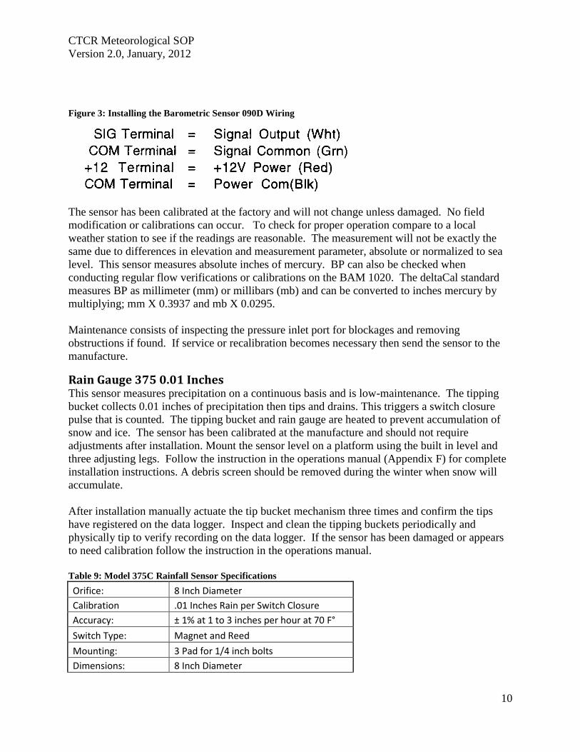
CTCR Meteorological SOP
Version 20 January 2012
10
Figure 3 Installing the Barometric Sensor 090D Wiring
The sensor has been calibrated at the factory and will not change unless damaged No field
modification or calibrations can occur To check for proper operation compare to a local
weather station to see if the readings are reasonable The measurement will not be exactly the
same due to differences in elevation and measurement parameter absolute or normalized to sea
level This sensor measures absolute inches of mercury BP can also be checked when
conducting regular flow verifications or calibrations on the BAM 1020 The deltaCal standard
measures BP as millimeter (mm) or millibars (mb) and can be converted to inches mercury by
multiplying mm X 03937 and mb X 00295
Maintenance consists of inspecting the pressure inlet port for blockages and removing
obstructions if found If service or recalibration becomes necessary then send the sensor to the
manufacture
Rain Gauge 375 001 Inches This sensor measures precipitation on a continuous basis and is low-maintenance The tipping
bucket collects 001 inches of precipitation then tips and drains This triggers a switch closure
pulse that is counted The tipping bucket and rain gauge are heated to prevent accumulation of
snow and ice The sensor has been calibrated at the manufacture and should not require
adjustments after installation Mount the sensor level on a platform using the built in level and
three adjusting legs Follow the instruction in the operations manual (Appendix F) for complete
installation instructions A debris screen should be removed during the winter when snow will
accumulate
After installation manually actuate the tip bucket mechanism three times and confirm the tips
have registered on the data logger Inspect and clean the tipping buckets periodically and
physically tip to verify recording on the data logger If the sensor has been damaged or appears
to need calibration follow the instruction in the operations manual
Table 9 Model 375C Rainfall Sensor Specifications
Orifice 8 Inch Diameter
Calibration 01 Inches Rain per Switch Closure
Accuracy plusmn 1 at 1 to 3 inches per hour at 70 Fdeg
Switch Type Magnet and Reed
Mounting 3 Pad for 14 inch bolts
Dimensions 8 Inch Diameter
CTCR Meteorological SOP
Version 20 January 2012
11
Power Requirement 110 VAC
Weight 75 Pounds
Quality Control and Quality Assurance Quality Control (QC) and Quality Assurance measure are minimal due to the reliability and low
maintenance of the meteorological sensors employed The following table list all standards
used maintenance needed and actions If sensors exhibit characteristics outside of these
parameters the manufacturer will be contacted for instructions Records related to Meteorological
sensors will be tracked on the site log and summaries semiannually
Table 10 Meteorological Sensor Quality Control and Assurance Measures
Sensor Criteria Action
BX-596 ATBP Sensor
BP varies more than plusmn10 mm Hg from deltaCal Standard BAM 1020 Calibration Following SOP
Temperature varies more than plusmn2degC from deltaCal Standard BAM 1020 Calibration Following SOP
Sensor shield andor probe damaged Contact Met One for instructions
BX-592 Outside Temperature Sensor Volumetric Flow
Temperature varies more than plusmn2degC from deltaCal Standard BAM 1020 Calibration Following SOP
Temperature shield andor probe damaged Contact Met One for instructions
Model 505 Wind Sensor
Yearly zero test reading 00 to 01 ms wind speed
Contact Met One for instructions if greater than these readings
Yearly span test
Contact Met One for instructions if readings do not match those shown in Table 6
Heater not functioning Contact Met One for instructions
Relative HumidityTemperature
Sensor 083D
Yearly check for reasonableness Compare with local weather station
Yearly check for operation Blow on sensor and confirm RH rise
Barometric Sensor 090D Yearly inspection
Clean pressure inlet port for blockages when needed
Compare to deltaCal Standard Contact Met One for instructions if values do not compare reasonably
Rain Gauge 375 001 Inches
Yearly check for operation Manually tip bucket and confirm reading
Yearly check for level Use adjustment legs to level
Damage or bucket set screws loose
Follow instructions in operation manual for calibration
CTCR Meteorological SOP
Version 20 January 2012
12
Reference EPA Requirements for Quality Assurance Project Plans EPA QAR-5 Office of Environmental
Information Washington DC EPA240B-01003 March 2001
Guidance for Quality Assurance Project Plans EPA QAG5 Office of Environmental
Information Washington DC EPA240R-02009 December 2002
Guidance for Preparing Standard Operating Procedures (SOPs) EPA QAG-6 Office of
Environmental Information Washington DC EPA6000B-07001 April 2007
Met One Instruments Inc (2008) BAM 1020 particulate monitor operation manual Prepared by
Met One Instruments Inc Grants Pass OR BAM-1020-9800 Rev G
Standard Operating Procedure for the Continuous Measurement of Particulate Matter Monitoring
Sites Confederated Tribes of the Colville Reservation Air Quality Program August 2011
CTCR Meteorological SOP
Version 20 January 2012
13
Appendices
BX-596 ATBP SENSOR MANUAL
Met One Instruments Inc 1600 Washington Blvd Grants Pass Oregon 97526 Telephone 541-471-7111 Facsimile 541-541-7116
BX-S9G Sensor Manual - copy Copyright 2007 Met One Instruments Inc All Rights Reserved worldwide No part of this publication may be reproduced transmitted transcribed stored in a retrieval system or translated into any other language in any form without the express written permission of Met One Instruments Inc
Appendix A BX-596 ATBP Sensor Operation Manual
About this Manual
The BX-596 is an optional combination ambient temperature and barometric pressure sensor for use with the BAM-1020 particulate monitor The BX-596 sensor is a required accessory for all BAM-1020 configured to sample PM25 levels effective March 2007 The sensor provides ambient temperature and pressure data to the unit for actual (volumetric) flow control and flow statistics during the hourly sample cycle The BX-596 is only compatible with BAM-1020 firmware version 324 or later This manual describes the installation and operation of the BXshy596 sensor Refer to the BAM-1020 operation manual as needed
The BX-596-1 is an extended range version for extreme cold or high altitude environments
BX-59G TemperaturePressure Sensor Installed on a BAM-1020 Inlet Tube
Specifications
I
I I
I
I
I I
BX-59G Barometric Pressure Ambient Temperature Voltage Output o to 25 volts o to 25 volts
Range 525 to 825 mmHg -40 to +55 deg C Accuracy plusmn025 mmHg 25 C plusmn 15C above -30
10 Voltage 350 volts DC plusmn 02
BX-59G-1 Barometric Pressure Ambient Temperature i
Voltage Output o to 25 volts o to 25 volts Range 400 to 825 mmHg -50 to +50 deg C
Accuracy plusmn15 mmHg plusmn 15C full scale 10 Voltage 410 volts DC plusmn 02
BX-596-98DD Manua RevBdoc Page 1 of 4
Appendix A BX-596 ATBP Sensor Operation Manual
Installation and Setup
Ensure that the BAM-1020 is sited and installed properly per the instructions in the operation manual
During the installation process you will need to provide an access point for the BX-596 sensor cable to enter the shelter where the BAM-1020 is installed In some cases it is easiest to simply drill a 38 hole through the roof of the shelter about six inches away from the inlet tube then feed the cable through the hole and caulk around it to prevent leaks
There may be a better place to feed the cable into the shelter in some applications The BXshy902903 environmental shelters supplied by Met One have pre-formed access holes in the side to allow the sensor cable to be routed to the BAM-1020 Decide the best way to route the cable into the shelter The BX-596 comes with a standard 25-foot sensor cable Longer cables may be ordered if required
Remove the PM 10 head and PM25 cyclone from the top of the BAM inlet tube Attach the BXshy596 to the inlet tube (about 8 to 18 inches from the top) with the supplied U-bolt hardware Make sure that the sensor is level and tighten the U-bolt securely
Make sure the BAM-1020 is turned off then attach the sensor cable to the connector on the bottom of the BX-596 Route the loose end of the cable into the shelter and to the back of the BAM-1020 Coil up any excess length of cable Attach the cable to the back of the BAM as shown in the following table
I
BX596 ATBP Sensor Connections Wire Color Function BAM Terminal
Yellow A T Signal Output Channel 6 SIG BlackShield Ground Channel 6 COM Red +12 VDC Channel 6 POWER Green Auto 10 Signal 350V Channel 6 10 White BP Signal Output Channel 7 SIG
Reinstall the PM10 head and PM25 cyclone and seal around the cable hole with silicone if required
Operation
When the BAM-1020 is powered up with a BX-596 installed the unit will automatically sense the 10 voltage from the sensor and configure input channels six and seven to read and scale the outputs from the sensor Note The BX-596 sensor requires BAM-1020 firmware revision 320 or later The BX-596-1 extended range version requires BAM-1020 firmware revision 362 or later If the BAM firmware is not current enough then the BAM will not automatically identify and scale the sensor
Appendix A BX-596 ATBP Sensor Operation Manual
Turn ON the BAM-1020 and perform a calibration of the BX-596 Note The calibration is performed in the TESTgt FLOW screen which will not be available unless the FLOW TYPE is set to ACTUAL in the SETUPgt CALIBRATE screen You will need a reference standard measurement for ambient temperature and barometric pressure
MULTIPOINT FLOW CALIBRATION TARGET BAM STD
ltCALgt ~~~ 238 238 C BP 760 760 mmHg
FLOW 1 150 150 150 LPM FLOW 2 183 183 183 LPM FLOW 3 167 167 167 LPM
CAL NEXT DEFAULT EXIT
1 Enter the TESTgt FLOW menu as shown above The nozzle will lower automatically when this screen is entered The BAM colurnn is what the BAM-1020 measures for each parameter and the STO column is where you will enter the correct values from your reference standard The ltCALgt symbol will appear next to the parameter selected for calibration
2 Measure the ambient temperature with your reference standard positioned near the BXshy596 sensor Enter the value from your reference standard into the STO field using the arrow keys Press the CAL hot key to correct the BAM reading The BAM and STO values should now be the same
3 Press the NEXT hot key to move the ltCALgt indicator to the BP field and repeat the same steps for barometric pressure
The DEFAULT hot key can be pressed to reset the user calibration from the selected parameter and replace it with a factory setting The DEFAULT calibration should be fairly close in most cases
The BX-596 sensor is almost always calibrated as part of a BAM-1020 flow calibration Always calibrate the AT and BP channels before calibrating the flow channels as the flow rate is affected by the temperature and pressure of the ambient air
The 8X-596 temperature output may also be checked in an ice bath The ice bath test is usually never done except in some cold weather environments First calibrate the sensor at ambient temperature then use the following steps
1 Remove the stop screw from the bottom of the mounting bracket so that the electronics module is free to rotate Rotate the module counter-clockwise until it disengages from the keyhole slots and comes free from the radiation shield
2 The sensor comes with an 18 inch long ice bath extension harness This may be used to allow the temperature bead to reach the ice bath if necessary Carefully unplug the black temperature bead assembly from the top of the electronics module and install the harness between the bead and the module
3 Insert the temperature bead into the ice water bath along with your reference sensor Avoid immersing the bead assembly past the connector
Appendix A BX-596 ATBP Sensor Operation Manual
4 Allow the bead to equilibrate then compare the AT reading in the TESTgt FLOW screen to your reference sensor The readings should match within plusmn15 degrees C for the BXshy596-1 extended range sensor Note The tolerance for the regular BX-596 standard range sensor is plusmn 25 C in temperatures below -30C
5 Remove the ice bath harness and reassemble the sensor
During operation of the BAM-1020 the output from the BX-596 can be viewed from the main flow statistics screen or the OPERATE screens See the BAM-1020 manual
JI -~J
1 1~
i gt
-- --- shyv_
Ice Bath Extension Harness
Maintenance The BX-596 is designed to be low-maintenance easy to access and resistant to harsh environments There are only a few maintenance items for the sensor besides routine calibration checks
bull Remove the bottom cover and make sure that the four holes in the cover plate are clear and have not been obstructed by insects or debris These holes allow the air pressure to equilibrate inside the sensor for the barometric pressure reading Clean the inside of the electronics enclosure every 12 months or as needed
bull Clean the radiation shield assembly at least once per year Dirty shields reflect away solar radiation less efficiently
bull The circuit board is not intended to be removed or serviced by the customer bull The black temperature bead assembly may be replaced if the bead becomes damaged
The assembly simply plugs into the top of the electronics module The sensor will need to be recalibrated any time the temperature bead is replaced
Technical Support
Should you still require support after consulting your printed documentation we encourage you to contact one of our expert Technical Service representatives during normal business hours of 700 am to 400 pm Pacific Standard Time Monday through Friday In addition technical information and service bulletins are often posted on our website Please contact us and obtain a Return Authorization (RA) number before sending any equipment back to the factory This allows us to track and schedule service work and expedite customer service
Phone (541)471-7111 Fax (541)471-7116 E-Mail servicemetonecom Web wwwmetonecom
Mail Technical Services Department Met One Instruments Inc 1600 NW Washington Blvd Grants Pass OR 97526
Appendix A BX-596 ATBP Sensor Operation Manual
warranty
Products manufactured by Met One Instruments Inc are warranted against defects in material and workmanship for a period of one (1) year from the date of shipment from the factory Offered products not manufactured by Met One Instruments Inc will be warranted to the extent and in the manner warranted by the manufacturer of that product
Any product found to be defective during the warranty period will at the option of Met One Instruments Inc be replaced or repaired In no case shall the liability of Met One Instruments Inc exceed the purchase price of the product
This warranty may not apply to products that have been subject to misuse negligence accident acts of nature or that have been altered or modified other than by Met One Instruments Inc Consumable items such as bearings and batteries are not covered under this warranty
Other than the warranty set forth herein there shall be no other warranties whether expressed implied or statutory including warranties of fitness or merchantability
Service
Ary product being returiled to Met One Instruments In for service repair or calibration must be assigned a return authorization (RA) number Please call (541) 471-7111 or (972) 412-4715 for an RA number and shipping instructions
Products manufactured by Met One Instruments Inc that are returned for service repair or calibration are warranted against defects in material and workmanship for ninety(90) days from date of shipment under the same conditions as stated above
999
Appendix A BX-596 ATBP Sensor Operation Manual
Temperature Probe amp Shield Model BX-592
Operation Manual BX-592-9800
1600 Washington Blvd Regional Sales amp Service Grants Pass Oregon 97526 3206 Main St Suite 106
Met One Instruments
Telephone 541-471-7111 Facsimile 541-541-7116
Rowlett Texas 75088 Telephone 972-412-4715 Facsimile 972-412-4716
Appendix B BX-592 Temperature Probe and Shield Operation Manual
Model BX-592 Temperature Probe amp Shield Operation and Installation Manual
INTRODUCTION The Model BX-592 is a temperature probe and shield for use with the BAM-1020 particulate analyzer The BX-592 is used specifically with the BX-962 Volumetric Flow Control System used on the BAM-1020 This sensor provides temperature measurement of the outside air used to determine the temperature correction value as part of the volumetric flow calculation The sensor is designed to be connected directly to one of the analog input channels of the BAMshy1020 The BX-592 is used when there is no other source of analog temperature output from an existing temperature system at the owners location The BX-592 includes 30 ft of cable as well as a mounting adapter that attaches to the inlet tube of the BAM-1020
INSTALLATION The BX-592 is installed outside near the intake of the BAM-1020 particulate analyzer Mounting hardware is provided for direct mounting on the BAM-1020 inlet tube as shown in figure 10 Attach the temperature probe and shield to the horizontal bar using the clips on the top of the temperature shield Push the shield up onto the horizontal bar and press the grey plastic clips together until you hear the snap of the retainer locking inplace
The fitting on the mounting arm should be mounted in a convenient place near the top of the inlet tube and out of the way of the supports used to hold the inlet tube in place Tighten the set screws on the mounting adapter to hold it in place on the inlet tube The horizontal bar can be moved as necessary to mount the shield in a suitable location near the inlet tube and the PM-10 or PM-25 inlet assembly
The cable from the sensor can then be run down through the roof of the shelter or building so that it can be connected to the sensor input channel terminal block on the back of the BAMshy1020 unit
Figure 1 Temperature Sensor Installation
BX-592 Manual 31JAN2001 2
Appendix B BX-592 Temperature Probe and Shield Operation Manual
The sensor input connection should be made at sensor location six This input channel is the one used for any external temperature analog input used for the temperature correction input required by the volumetric flow controller
The BX-592 Temperature Sensor and Shield provides a special ider1tification output signal that is used by the BAM-1020 to determine what type of sensor is connected to the BAM as well as determine what the range of the temperature sensor The electrical connections to the BAMshy1020 can be see in Figure 2 Be sure that the color code of the individual wires of the cable is followed so that the sensor is not connected incorrectly to the BAM-1020 There are four wires which are connected to the four terminals of the analog inputs at the back of the BAM unit
IO~=== laquo) SIG ~2P-~~~WHTd COM ~~BLK ----~_4z ~ PWR ~2P-REO ----- I I 0 ~d)J-GRN --shyUL=== ~
SIG ~
Figure 2 Sensor Connections to BAM
Figure 2 shows the connections from the BX-592 Temperature Sensor and Shield to the BAMshy1020 Particulate Analyzer Be sure that the temperture sensor cable is connected to channel 6 of the BAM-1020 otherwise the voltage output of the sensor will not be able to be used as the temperature reference of the volumetric flow controler
For correct operation of the volumetric flow control option BX-961 the BAM-1020 must be programmed for volumetric flow operation This is done from the SETUP then CALIBRATE and then FLOW TYPE screen The default is metered flow and will need to be set for volumetric flow for tt1ts option to work correctly See the BAM-1020 Manual section 414 for information on the Calibrate Screen and in section 63 for information on the field calibration of the flow system
SPECIFICATIONS The following are the specifications of the BX-592 Temperature Sensor and Shield These are subject to change as determined by Met One Instruments Inc The shield of the BX-592 provides protection of the temperature probe from errors that are caused by direct solar radiation The shape allows for the wind to naturally aspirate the shield to reduce the total effect of solar radiation on the temperature measurement
Temperature Probe Type Thermistor Bead multi-element
Temperature Accuracy
Temperature Range
Sensor Output o to 1 VDC for temperature range
Time Constant 10 Seconds in still air
BX-592 Manua13IJAN2001 3
Appendix B BX-592 Temperature Probe and Shield Operation Manual
The shield is mounted from the top of the shield using two snap clamps designed for a 1 diameter tube or a IPS Pipe The mounting adapter and a short boom are provided for attachment to the inlet tube of the BAM-1020
MAINTENANCE amp CALIBRATION The temperature probe and shield require no specific maintenance other than normal cleaning of dirt and dust to prevent the degredataion of the reflectiveness of the shield If there is any build up of materials inside the shield they should be cleaned out so that there is a free path for air flow around the temperature probe
On a regular basis the output of the temperature probe displayed on the screen of the BAMshy1020 should be checked against a reference thermometer to be sure that the BX-592 is providing accurate information for the calculation of volumetric flow There are no adjustments inside the temperature probe and any repairs should be handled by the factory
Before returning a faulty probe the factory should be contacted a RA (Return Authorization) should be obtained and the problem noted on the RA This will insure that the repairs are made quickly and returned for installation
TROUBLE SHOOTING
Symptom Identify Problem Solution Incorrect Temperature indicated on BAM Display
Verify that connections to the rear panel of the BAM are correct and to channel 6
Change wiring to follow diagram as indicated in figure 2 of this manual
From setup menu channel Change settings from parameters screen verify that MANUAL Mode to Auto ID channel 6 is set for Auto ID mode for probe to work and not in MANUAL Mode correctly Examine output of BX-592 to Using a volt meter measure verify that it has the correct voltage between the black and voltage output for the current white wires 0-1 volt is ambinet temperature equivalent to -30 to 50
degrees C Le 21degC =637 volts If this is not correct return probe for repair
Volumetric Flow Control is not operating
Go to the Setup then Calibrate screen menu and verify that the flow type is set to volumetric and not metered
Default setting is for metered it will be necessary to change setting to volumetric flow type
Examine rear of BAM-1020 and see if there is a flow adjusment knob on the back of the unit right above the vacuum line
If there is a knob here it is most likely that volumetric flow control is not installed on this unit Contact Met One Instruments for advice
Volumetric flow value does not match audit flow meter connected to BAM
From setup menu select flow and examine the current measured flow value of the BAM
Recalibrate the BAM flow meter using the proceedure in the manual section 63 Field Calibration of Flow System
Verify that the audit instrument being used has been calibrated for volumetric flow monitoring
Adjust flow audit device for correct measurement of volumetric flow
BX-592 Manual 3IJAN200 1 4
Appendix B BX-592 Temperature Probe and Shield Operation Manual
For any other specific problems with the BX-592 or the Volumetric Flow Option BX-961 contact the factory
Met One Instruments Inc 1600 NW Washington Blvd Grants Pass Oregon 97527
(541) 471-7111 Voice (541 ) 471-7116 FAX
service metonecom e-mail
Visit our web page at httpwwwmetonecom
BX-592 Manual 31JAN2001 5
Appendix B BX-592 Temperature Probe and Shield Operation Manual
MODEL 505 WIND SENSOR
OPERATION MANUAL Document No 505-9800
1600 Washington Blvd Grants Pass Oregon 97526
Met One Telephone 541-471-7111 Instruments Facsimile 541-541-7116
Regional Sales amp Service 3206 Main St Suite 106 Rowlett Texas 75088 Telephone 9724124715 Facsimile 972-412-4716
505-9800 Rev Edoc
Appendix C Model 505 Wind Sensor Operation Manual
Copyright Notice
505 Sonic Wind Sensor Manual
copy Copyright 2005 Met One Instruments Inc AI Rights Reserved Worldwide No part of this publication may be reproduced transmitted transcribed stored in a retrieval system or translated into any other language in any form by any means without the express written permission of Met One Instruments Inc
Technical Support Should you require support please consult your printed documentation to resolve your problem If you are still experiencing difficulty you may contact a Technical Service representative during normal business hours-730 am to 400 pm Pacific Standard Time Monday through Friday
Voice (541) 471-7111
Fax (541) 471-7116
E-Mail servicemetonecom
Mail Technical Services Department Met One Instruments Inc 1600 Washington Boulevard Grants Pass OR 97526
505-9800 Rev E Page 2
Appendix C Model 505 Wind Sensor Operation Manual
TABLE OF CONTENTS 1 GENEAAL INFORIIATION 5
2 INSTALLATION 5
21 LTNPACKlNG 5 22 PREPARATION 5 23 SENSOR SITING 6
Figure 2-1 Siting Wind Instroments 6 24 ORIENTATION WITH FIXTURE 7
Figure 2-2 Orientation Fixture 7 25 ORIENTATION WITHOUT FIXTURE (SEE FIGURE 2-3 AND 2-4) 8 26 EXTERNAL HEATER 8
Figure 2-3 505 Wind Sensor Components 9 Figure 2-4 Alignment aSensor to Troe North 10
27 INSTALLATION OF AVERY DETERRENTS 11 Figure 2-5 InstallatIOn ofAviary Delerrents I
28 CONNECTIONS TO RECORDING ELECfRONICS 12
Figure 2-7 Factory Standard Analog amp Rf-232 Output Connections (Cable 9574 wi Differential Amplifier
Figure 2-8 Factory Custom SDI-12 Output Connections 3
Figure 2-6 Amplifier (9573) attached to Cable (9574) and wiring in box 12
9573) 12
Figure 2-9 Factory Custom RS4221485 Output Connections 13 28 SIGNAL OUTPUTS ANALOG RS-232 ANDSDI-12 13 29 SIGNAL OUTPUTS - RS422 AND RS485 14
3 OPERATIONAL CHECK-OUT AND CALmRATION 14
31 GENERM 14 32 RECORDING ELECTRONICS 14 33 ZERO TEST 14 34 SPAN TEST 14
4 MAINTENANCE AND TROlTBLESHOOTING 15
41 GENERAL MAlNTENANCE SCHEDULE 15 42 TROlTBfJESHOOTING 15
5 TIIEORY OF OPEAATION 16
51 SPEED OF SOUND IN AlR 16 52 SPEED OF S()UND PRINCIPLE 16 53 CALCULATION OF THE WIND VELOCITy 16
6 SPECIFICATIONS 17
FIGURE 6- 505 Wind Sensor Outline Dimensions 18
APPENDIX A - WIND DIRECTION SENSOR ORIENTATION 19
APPENDIX B - WIND SENSOR MOUNTING OPTIONS 22
APPENDIX C - HEATER CONFIGURATION AND WIRING 23
APPENDIX D - RS2J2 COMMAND SET 25
GENERAL PROTOCOL 25
1 RS-2J2 DATA OUTPUT PROTOCOL 25
11 ERROR CODE 26
2 USER COMMAND SET _ 27
21 L8-VERBOSE CONTROL OF RS-232 PARAMETER LABELS 27
505-9800 Rev E Page 3
Appendix C Model 505 Wind Sensor Operation Manual
22 MS-MAxLMUM FULL SCALE WIND SPEED 27 23 SU-WINO SPEED UNITS 27 24 QU-QUlT 27 25 SB-SERIAL BAUD RATE 28 26 ST-SERIAL TRIGGER (RS-485 ONLy) 28 27 IT-SONIC TEMPERATURE 28 28 VN-VERSION NUMBER 28 29 VS-FULL SCALE ANALOG OUTPUT VOLTAGE FOR WINO SPEED Ai~O WINO DIRECTION 28
505-9800 Rev E Page 4
Appendix C Model 505 Wind Sensor Operation Manual
MODEL 505 WIND SENSOR OPERATION MANUAL
1 GENERAL INFORMATION
The Met One Instruments Model 505 Wind Sensor is a solid-state ultrasonic instrument capable of measuring wind speed and wind direction in the U and V axes Sonic pulses are generated at the transducers and are received by opposing transducers Mathematics derived for these sonic pulses provide a wind velocity measurement in each of the corresponding axes
The 505 uses a microprocessor-based digital electronic measurement system to control the sample rate and compute the wind speed and wind direction The sensor is factory calibrated and requires no field calibration In the field the operation of the sensor can be quickly checked using a combination of simple tests A zero chamber or bag is used to verify the zero reference by covering the entire sensor or individual outputs are checked by blocking various combinations of sensors
The 505 provides are variety of outputs to suit the connection requirements of the user Standard outputs are voltage and RS-232 SDI-12 and RS422485 outputs are configured at the factory
2 INSTALLATION
21 UNPACKING
Carefully remove the sensor from its shipping container and inspect it for damage Referring to the packing list check for shortages Any claims for damages should be filed promptly with the carrier
The sensor is a precision electromechanical transducer Always handle it with care exercising particular caution to ensure that the instrument is not subjected to side loading shock or other abuse After initial inspection keep the sensor in its shipping container for protection until actual installation
22 PREPARATION
For accurate measurements the sensor mount must be rigid with little or no movement from the wind The sensor is designed for installation in a Model 3188 mounting and alignment fixture This provides a mount for use on a horizontal IPS pipe (105- 00) boom Mounting information and diagrams can be found in Appendix B of this manual
The 3188 Sensor Mounting Fixture includes a keyed bushing which will be adjusted for alignment to North orientation This enables the sensor to be removed and replaced without requiring realignment Three captive machine screws are used to secure the sensor to the keyed bushing
If a temperature shield such as the Model 0738 is to be used in the configuration the Model 1539-4 Arm and 1552 Mount is recommended These parts provide the necessary mounting for a vertical mast of 0 IPS pipe (105 OD) This same configuration can also be used to mount other sensors as well as providing a way to mount the sensor on a vertical mast (See Appendix B for Mounting Details)
505-9800 Rev E Page 5
Appendix C Model 505 Wind Sensor Operation Manual
23 SENSOR SITING
The primary objective of instrument siting is to place the instrument in a location where it can make precise measurements that are representative of the general state of the atmosphere in that area Because most atmospheric properties change dramatically with height and surroundings certain somewhat arbitrary conventions must be observed so that measurements can be compared
lOT
Figure 2-1 Siting Wind Instruments
The standard exposure of wind instruments over level open terrain is 10 meters above the ground (WMO 1971) however optimum measurement height may vary according to data needs Open terrain is defined as an area where the horizontal distance between the wind sensor and any obstruction is at least ten (10) times the height of that obstruction An obstruction may be man-made (such as a building) or natural (such as a tree) (See Figure 2-1)
The wind instrument should be securely mounted on a mast that will not twist rotate or sway If it is necessary to mount the wind instrument on the roof of a building it should be mounted high enough to be out of the area in which the airflow is disturbed by the building This is usually 15 times the height of the building above the roof so that it is out of the wake of the obstruction This is not a good practice however and should only be resorted to when absolutely necessary
Wind instruments are best sited when they are used on towers The tower should be located in an open level area representative of the area under study Towers should be of the open grid type of construction such as is typical of most television and radio broadcast towers Enclosed towers stacks water storage tanks grain elevators cooling towers and similar structures should not be used
Wind instruments should be mounted above the top of the tower on booms projecting horizontally out from the tower If a boom is used it should support the sensor at a distance equal to minimum of twice or at best three times the maximum diameter or diagonal of the tower away from the nearest point on the tower On large towers with large verticals it may be best to place the sensor at least 5 tower leg diameters from the tower leg The boom should project into the direction which provides the least distortion for the most important wind direction For example a boom mounted to the east of the tower will provide least distortion for north or south winds
505-9800 Rev E PageS
Appendix C Model 505 Wind Sensor Operation Manual
Weather sensors are sensitive to direct or nearby lightning strikes A well-grounded metal rod or frame should be placed above the sensor installation In addition the shield on the signal cable leading to the translator must be connected to a good earth ground at the translator end and the cable route should not be vulnerable to lightning
24 ORIENTATION WITH FIXTURE
The Orientation Fixture Model 705 is used for very accurate positioning of the 505 sensor with respect to a benchmark or other object that can be visually obselVed If a compass is used to establish a benchmark the reading should be taken away from heavy metal objects which can affect the reading and should be corrected for declination of the magnetic north pole The benchmark is set to true north of the sensor site Information on determining true North can be found in Appendix A of this manual
The fixture contains a telescopic sight with crosshairs and includes a keyed base identical to that on the sensor The fixture is specifically designed for use with the 3188 Sensor Mounting Fixture The base of the fixture is keyed so that the object lens of the sight assumes the same position as the north side of the sensor
Before orienting the sensor ensure that it is vertical and adjust the cross arm as necessary Orientation of the sensor is then performed with the fixture installed on the cross arm in place of the sensor (The three screws in the base of the fixture must be tightened to ensure proper orientation in the cross arm) Loosening the three setscrews on the side of the sensor mount allows free rotation of the keyed bushing and orientation fixture The ring and fixture are then rotated to position the benchmark in the center of the sight crosshairs The sight can be tilted as necessary by loosening the slotted screw on the side of the fixture The set screws are then tightened the fixture removed and the sensor installed in its place The sensor is now oriented for zero (north) wind direction signal output when the wind is from north
OSIECTlENS
Figure 2 2 Orientation Fixture
The electrical connector on the bottom of the sensor should be properly mated to the cable connector and the three captive screws on the base of the sensor should be tightened
When using the orientation fixture assure that the two-piece mounting assembly is properly aligned The upper half of the assembly contains a horizontal peg which must seat in the vshynotch located in the lower half The knurled knob on the lower half is used to secure the two sections and should be tight
505-9800 Rev E Page 7
Appendix C Model 505 Wind Sensor Operation Manual
25 ORIENTATION WITHOUT FIXTURE (See FIGURE 2-3 and 2-4)
Establish a True North benchmark See Appendix A for aids to determine True North This should be a point directly north from the sensors mounted location This point should allow easy access so that a person may sight the sensor with a spotting telescope If a compass is used to establish a benchmark the reading should be taken away from heavy metal objects which can affect the reading and should be corrected for declination of the magnetic north pole The benchmark is set due north of the sensor site
One person is located at True North benchmark equipped with a spotting scope A second person is located at the sensor The sensor alignment may be established as follows
A Install the sensor into the alignment bushing and secure with the two setscrews under the 3188 Alignment Fixture Keep the three setscrews around the ring of the fixture loose so that the ring can be rotated into position
B Turn the sensor so that the sensor paints to the North benchmark Tighten the 3 setscrews and recheck align ment
C Connect the 9574-cable assembly to the sensor Secure cable to boom with cable ties or tape to prevent damage
D The sensor can be removed without requiring realignment at any time Simply remove the sensor The alignment bushing remains proper1y oriented in the fitting
26 EXTERNAL HEATER
The Optional External Heater provides de-icing for the sensor arms and prevents the accumulation of ice which might block the sonic sensor elements The heater consists of a laminated heater material that is custom designed and wrapped around the four sensor arms and sonic sensor element housings The heater controller requires 15 to 24 VACNDC at approximately 4-5 amps at startup There are jumper connections on the controller board for the selection of power source The controller is normally provided with the jumpers not installed This is for 24 volts AC operation of the heaters Heater power can be supplied from a power transformer or a Met One Instruments supplied power unit in a weatherproof box The proportional controlled heater uses maximum current at start-up and power requirement goes down as the sensorheater reaches stability The heater is activated at 38 degrees F and will keep the arms ice-free at temperatures down to below -20 degrees F The connection information can be found in Appendix C of this manual
The temperature controller electronics box should be mounted no more than 5 feet from the sensor using the cable supplied with the heater controller The power cable should be of minimum 16 AWG wire and cable length should be at a minimum to prevent power loss due to cable resistance at the 4-amp power requirement
505-9800 Rev E Page 8
Appendix C Model 505 Wind Sensor Operation Manual
MODEL 505 WINO SENSOR
NORTH SCREWPIN ____~~--
THIS SIDE TO FACE SOlTTH LABEL
NORTH SLOT HOLE~middot-c-lIIo-
SET SCREWS (3 EA FOR SECURING
KEYED BUSHING TO HORTH ORIENTATION
(7164- ALLEN KEY)
Figure 2-3 505 Wind Sensor Components
Page 9 505-9800 Rev E
Appendix C Model 505 Wind Sensor Operation Manual
SOUTHSIDE SENSOR TRANSDUCER SHOULD BE SEEN EaUALLY DIVIDED
BY NORTHSIDE (NEAR) ARM
Figure 2-4 Alignment of Sensor to True North
505-9800 Rev E Page 10
Appendix C Model 505 Wind Sensor Operation Manual
27 INSTALLATION OF AVERY DETERRENTS
To prevent birds from entering the pathway between the sensors a vertical stainless steel rod is located in the center of the sensor array_ To keep birds from perching on the sensors stainless steel wire aviary deterrent need to be installed on the sensor prior to installation in the fixture
NOTE The stainless steel wires used for the aviary deterrents are very sharp The wire is spring steel and there s the possibility that it could slip off during the installation Use care
when installing the aviary deterrent and be careful after installation
PROTECTIVE GLASSES SHOULD BE WORN DURING INSTALLATION
Installed A viarv Deterrents
area
AVIARY DETERRENTS bull PIIIih ends IowaIds eoch ltlttler lil qgten up
spring d1amccr bull Slide owr lranllducer 10 mounIing llIII bull ~6l as requRd 60 that avlary
delemK1N are pointed ~
MOUNTING AREA
Figure 2-5 Installation of Aviary Deterrents
WARNING If the aviary deterrents are not properly installed The sensor may experience signal degradation Install as shown DO NOT allow for the spring section of the aviary deterrent to contact the transducer portion of the sensor array_
505-9800 Rev E Page 11
Appendix C Model 505 Wind Sensor Operation Manual
28 CONNECTIONS TO RECORDING ELECTRONICS
Route the cable to the data-recording device Secure the cable with cable ties or tape The 9574shycable assembly contains 7 wires and a shield Typical wiring hookup is shown in the figures below Actual wiring will depend upon the version of the sensor To determine which of the three connections drawings apply examine the cable part number at both ends of the cable
Cable type 9574 includes the 9573 Differential Amptifier it is located at the end of the cable opposite the sensor connector The amplifier provides high immunity to any noise that might be picked up the sensor cables It is recommended that this cable with amplifier be used whenever connected to a single ended input recorder If necessary to remove the differential amplifier a wiring diagram has been included in the top of the small amplifier enclosure A small screwdriver is provided for use on the small terminal screws on the PC Board of the 9573 Amplifier Be sure that the connection color codes are followed so that no wiring error occurs See below
Warning If you are connecting this 505 to an older 3155-cable assembly and are using the black wire as signal common disconnect it because it will short out the RS-232 transmitter No damage will occur to the circuit but the 505 current consumption will increase by 20 rnA
TO SONIC
~ n 0 SHLD (WTIBN) +12Y(Wiri) 0 0 NIC wo oOt-(RpoundD 0 0 GND(GRN) WD 0lIT~ (OAN) 0 0 ncD(8LK) W8 ~+(BLU) 0 0 RXC(IRN) NC 0 0 WSIN+(BW) RXD(8fCN) 0 0 NIC TXDl8LJC) 0 0 WDW+(RED) OND(GRN) 0 0 WDIN-(ORN) NIC Omiddot 0 +12V(WtfT) SHLD (WTIBN) 0 J1 r-
TO DATALOGGIR
Figure 2-6 Amplifier (9573) attached to Cable (9674) and wiring in box
Sensor Common
Power Common WHITE
RED
+12V Power
BROWN RXRS-232 BLACK TXRS-232
Wind Direction Voltage BLUE OR YELLOW Wind Speed Voltag~
Shield WHITEBROWN
Figure 2-7 Factory Standard Analog amp RS-232 Output Connections (Cable 9574 wI Differential Amplifier 9573)
505-9800 Rev E Page 12
Appendix C Model 505 Wind Sensor Operation Manual
o NG[ GREEN WHITE
BROWN
aLACK
REO
BLUE OR YEllOW
Sensor Common
Power Common
+12VPower
Not Used
Not Used
Not Used SOI-12 Output
Shield WHITEBROWN
Figure 2middot8 Factory Custom SDI~12 Output Connections
ORANGE
RED
Sensor Common GREEN Power Common WHITE +12V Power
BROWN RX f
BLACK RX shy
TX+ BLUE OR YELLOW TX-
Shield WHITEBROWN
Figure 2-9 Factory Custom RS4221485 Output Connections
28 SIGNAL OUTPUTS - AnalogJ RS-232 and 501-12
The standard configuration of the sensor provides for a voltage outputs for wind speed and direction as well as RS-232 Data The default output voltage is 10 volts full scale for 50 meterssecond and 360 degrees of direction Alternate full-scale values can be changed by using the RS-232 command set discussed in Appendix O The R8-232 output occurs every second in the format S sssS 0 ddd ltcrgtltIfgt where ssss is the wind speed value up to 9999 and the direction ddd up to a value of 360 RS-232 output is at 9600 baud 8 data bits 1 stop bit and no parity
As an option an output of 801-12 Data from the sensor is available In this configuration it is the only available output and is in the format +ssss+ddd ltcrgtltlfgt The same values for sssS and ddd as the RS-232 format are output The 801-12 handshake is per the 801-12 specifications and format In this configuration the RS-232 output or analog output is no longer available from the sensor
505-9800 Rev E Page 13
Appendix C Model 505 Wind Sensor Operation Manual
29 SIGNAL OUTPUTS - RS422 and RS485
In this configuration the sensor has no analog outputs (see diagram Factory Custom RS422RS485 Output Connections The correct sensor cable for this configuration is part number 3379
The default serial trigger (sensor address) is 1 After receiving 1 the sensor will return wind speed and wind direction in the same format as with RS232 (S sSSs D ddd ltcrgtltlfraquo
To use the RS232 Command Set defined in Appendix 0 the sensor must first be put into Terminal Mode by sending (three exclamation points) The serial trigger is not used in this case and there must be only one sensor connected on the serial buss The sensor will return when in Terminal Mode and will then accept RS232 commands The au (quit) command will take the sensor out of Terminal Mode and return it to normal operating mode
3 OPERATIONAL CHECK-OUT AND CALIBRATION
31 GENERAL
Operation of the 50S is essentially automatic and no specific sensor calibration is required for normal operation The sensor has been calibrated in a wind tunnel at the factory prior to shipment
32 RECORDING ELECTRONICS
The sensor may be connected to a variety of data recorders and translators Standard wind speed range is O-SO mls and wind direction range is 0-360 degrees Standard output voltage is 0-10V with 0-2SV and O-SOV as available options Refer to the calibration certificate supplied with the sensor to determine the actual output
To ensure that the recorder is scaled properly it is recommended that zero and span tests are performed after the sensor is connected and operational
33 ZERO TEST
A zero test requires no air movement across the sensor array so a means of covering the array is needed A plastic bag can be placed over the array using care not to contact the transducers or block the sonic paths between transducers The bag should be spaced at least 2 above the transducers to avoid sonic reflections which may affect readings The bag can be tied at the bottom with a tie wrap or tape to prevent air movement from below Keep in mind that wind can defrect the bag causing air movement inside
The preferred method is to use a box insulated with foam to prevent reflections and spaced so that the top is at Jeast 2 above the transducers Again the bottom should be sealed around the sensor to isolate the array from ambient air movement
With no air movement across the array the sensor should indicate 00 to 01 ms wind speed The wind direction output will wander to any value between 0 and 360 degrees
34 SPAN TEST
The sensor is designed to produce known default outputs if an object blocks the sonic signal path between the transducers This feature is useful for verifying sensor operation and recorder scaling For testing purposes the sonic path can be blocked by placing a finger (or any solid object) on the face of one or more transducers
505-9800 Rev E Page 14
Appendix C Model 505 Wind Sensor Operation Manual
NOTE The following table defines the sensor outputs with blocked paths
Wind Speed Blocked Axis Serial Output North-South 100 mls East-West 100 mls 80th 100 mls
Analog Out~ut 50 mls 50 mls 50 mls
D-10V 100V 100V 100V
0-2SV 250V 250V 2S0V
O-SOV 500V SOOV SOOV
Wind Direction Blocked Axis Serial Output Analog Output D-10V 0-25V D-50V North-South 10 Deg 10 Deg 003V 007V 014V East-West 160 Deg 160 Deg O44V 111V 222V Both 170 Deg 1700eg 047V 118V 236V
4 MAINTENANCE AND TROUBLESHOOTING
The 50S sensor is sealed and there are no replaceable parts contained therein The sensor does not require periodic calibration and there are no internal adjustments that can be made
41 GENERAL MAINTENANCE SCHEDULE
12-24 month intervals
The Model 505 Wind Sensor should be inspected periodically for physical damage to the sensor array assembly cable and cable connections Inspect all transducers to be sure they are securely fastened
Schedule based on average to adverse conditions
42 TROUBLESHOOTING ------ --shy--=-----------------==-----~~---- ----~-~-~~~~~~---~-----~ ----~~~~~~~--
~________~piom _~ __ ____ _____ ~~o~babl~9_C1l1~~_~___ ~__+_-_-A-ct-io-n-to-R-eL-pa_ir__---i
Wind Speed output goes to full Blocked pathway 1 - Check path and clear scale
Failed sensor 2 - If clear contact factory for Return Authorization to repair sensor
Wind Speed output high but not Common mode voltage 1 - Replace cable with part full scale number 9574 (with 9573
differential-to- single-ended converter)
supply 2 - Use 3379 cable and power sensor with isolated power separate from recorder power supply
inputs 3 - Use 3379 cable and connect sensor signals to differential on recorder
505-9800 Rev E Page 15
Appendix C Model 505 Wind Sensor Operation Manual
5 THEORY OF OPERATION
51 SPEED OF SOUND IN AIR
The speed of sound in still air can be measured accurately between two points a few centimeters apart by two ultrasonic transducers set at that distance The resulting speed of sound is a known function of the air temperature and composition
The speed of sound waves in an ideal gas may be written
where R is the universal gas constant (083134 mJmol K) T is the temperature in Kelvin M is the molecular weight (gramsmol) of the gas and L is the ratio of heat capacities Cp and Gy Cp
and Cyare the specific heats at constant pressure and constant volume of the gas respectively
52 SPEED OF SOUND PRINCIPLE
The transit time of a sound signal traveling from one end of a sound path to the other separated by distance d can be written as follows (Schotand 1955)
where V is the total velocity Vdand Vnare velocity components in the directions parallel and normal to the sound path and C is the velocity of sound in still air If two transit times t1 and t2 in opposite directions on the same path are directed Vd can be obtained independent from V and Vn as follows
It is this principle that is used to compute the velocity of the air in the path between two opposing transducers
53 CALCULATION OF THE WIND VELOCITY
In still air t1 and t2 are equal For a distance 15 cm at 20deg C the transit time is approximately 450 IJs If a 20 mls wind is in the direction of the sonic pulse the transit time t1 will be approximately 427 IJs If the wind is opposing the sonic pulse the transit time will be approximately 482 IJs If these two values are used in the previous equation the resultant velocity from equation will be 20 ms
505-9800 Rev E Page 16
Appendix C Model 505 Wind Sensor Operation Manual
6 SPECIFICATIONS
Sonic Wind Sensor Model 606
Wind Speed Range Accuracy Resolution
Wind Direction Range Accuracy Resolution
Operation Sample Rate Data Output Rate Sonic frequency
Output Signals Wind speed voltage Wind direction voltage RS-232
Optional Digita) Outputs
Power requirement Sensor
External Heater Option
Environmental Maximum Measurement range Operating Temperature Extended Temperature Range
Physical Weight Dimensions
Options Signal Cable Horizontal Mount amp Orientation Fixture External Heater with Control Box External Heater Power Source Programming Cable amp Power Supply
oto 50 msec plusmn 02 rnIsec 113 msec or plusmn 2 gt- 113 msec 01 msec
5 per second 1 per second 200 KHz
0- 50 VDC (Specified at time of purchase) 0- 50 VDC (Specified at time of purchase) 1200 to 192K Baud
501-12 RS-422 or RS-485 (Specified at time of purchase)
9-18 VDC 10 mA 12 VDC Average power requires 75 amp pulse for 2msec
15 VDC 50 Watts
oto 65 mls -40degC to +55degC no ice -SOdegC to +55degC with external heater
S5 Ibs (25 Kg) 1929in (490mm) high 938in (238mm) diameter
PN 9S74 - Specify length PN 3188 SO5H 50SPS (100 to 240 VAC SO60 HZ) 1SVDC 4 amps TBD
Heater Options must be specified at time of purchase middotSpecifications Subject to Change without prior Notice
50S-9800 Rev E Page 17
Appendix C Model 505 Wind Sensor Operation Manual
LLJ-oIIIo----IOODfA
--20001t
FIGURE 6-1 505 Wind Sensor Outline Dimensions
505-9800 Rev E Page 18
Appendix C Model 505 Wind Sensor Operation Manual
APPENDIX A - WIND DIRECTION SENSOR ORIENTATION
INTRODUCTION Determining True North or Magnetic Declination is very important to the proper setup and orientation of the wind direction portion of the sonic wind sensor The declination value is used to determine the difference between True North and magnetic North This value varies around the world depending upon your location The following procedure can be used to either point the sonic wind sensor to True North
ADJUSTMENT Orientation of the wind direction sensor is done after the location of True North has been determined True North is usually found by reading a magnetic compass and applying the correction for magnetic declination where magnetic declination is the number of degrees between True North and Magnetic North Magnetic declination for a specific site can be obtained from a USGS topographic map pilots maps local airport or through a computer service offered by the USGS called GEOMAG
The following map showing magnetic declination for the contiguous United States is shown in the figure 1 can be used for determination of declination Tilis will depend upon the accuracy requirement required Alternately use a more accurate method of detemlining declination from magnetic North
Subtract declination from 3600 Add declination to 0deg 20W
Figure 1 typical declination values in the USA
Declination angles east of True North are considered negative and are subtracted from 0 or (360) degrees to get True North as shown in figure 2 Declination angles west of True North are considered positive and are added to 0 degrees to get True North as shown in figure 3 For example the declination for Grants Pass Oregon is 17deg East True North is 3600 -17deg or 3430 as read on a compass
505-9800 Rev E Page 19
Appendix C Model 505 Wind Sensor Operation Manual
Alignment to North Orientation is most easily done with two people one to aim and adjust the sensor while the other observes the wind direction display (Once True North is located the South reference can be determined)
1 Establish a reference point on the horizon for True North Sighting down the instrument centerline aim the two arms of the NorthSouth pair at True North with the locking set screw pointed South
2 Align the sensor adapter or adapter mount Loosen the setscrews that secure the base of the sensor to the cross arm While viewing the positionrotation of the Nortl1South sensor arms slowly rotate the sensor base until the two arms point to True North that was determined by earlier measurement using compass
Other methods employ observations using the North Star or the sun and are discussed in the Quality Assurance Handbook for Air Pollution Measurement Systems Volume IV Meteorological Measurements
Determining Local Magnetic Declination Several resources for determining the magnetic declination of any site in the world can be found on the internet or can be accessed by modem using any common terminal program
GEOMAG is a resource that can be accessed by telephone or the Internet (Telnet) connection GEOMAG is accessed by calling 1-800-358-2663 with a computer and telephone modem and communications program such as HyperTerminal GEOMAG can also be accessed by the internet using the address telnetllneiscrusgsgov
GEOMAG prompts the caller for site latitude longitude and elevation which it uses to determine the magnetic declination and annual change The follOWing Menu and prompts are from GEOMAG Use the username QED
MAIN MENU NeecJe POInfS toType Q for Quick Epicenter Determinations (QED) Magnetic North
L for Earthquake Lists (EaUST) M for Geomagnetic Field Values (GEOMAG) X to log out
Enter program option M
Would you like information on how to run GEOMAG (YN) N
FIGURE 2 Declination Angles East ofOptions True North Are Subtracted from 0 to Get True North 1 = Field Values(D I HXZ F)
2 =Magnetic Pole Positions 3 Dipole Axis and Magnitude 4 Magnetic Center
Display values twice [N] press return Name of field model [USCON951 press return Date [Current date] press return Latitude 4225 N Longitude 12320 W Elevation 1000 Units (mkmft) ft
FIGURE 3 Declinatiof1 Angles West of True North Are Added to 0 to Get True North
505-9800 Rev E Page 20
Appendix C Model 505 Wind Sensor Operation Manual
Example of report generated by GEOMAG Model USCON95 Latitude 4225 N Date 211399 Longitude 123120 W Elevation 1000000 ft
D I H X Y Z F deg min deg min nT nT nT nT nT
17 175 65 73 22056 21059 6555 47560 52425 Annual change 0 -24 0 -17 -29 18 -156 -662 -613
The calculated dedi nation would be 17 degrees and 175 minutes for Grants Pass Oregon The declination in the example above is listed as 17 degrees and 175 minutes Expressed in degrees this would be 173 degrees As shown in Figure 1 the declination for Oregon is east so True North for this site is 360 - 173 or 3427 degrees The annual change is -24 minutes In this case a value 343 degrees would probably be sufficient for most measurement accuracy
An alternative method is to find a USGS map and examine the text at the bottom center of the map At this point either a written indication is given or a symbol similar to the one seen below will be found This would indicate a declination of 15 degrees West-showing MN (magnetic North) to True North (Star) Other sources such as the local airport can be helpful in determining the correct declination
1D23 25 MilS
UTM GR-O AND 1971 MAGNETIC NORTH OECLINATION AT CENTER OF SHEET
505-9800 Rev E Page 21
Appendix C Model 505 Wind Sensor Operation Manual
r=======~ -C_ARM-c-r--r-___-r
193 MOUNTING BOOM
APPENDIX B - WIND SENSOR MOUNTING OPTIONS
TYPICAL VERTICAL MOUNTING WITH 191-6 CROSS ARM
3168 AtlGINT FlXTmE
TOP OF TOWER
TYPICAL HORIZONTAL MOUNnNG
3188 AlIGN1NT FIXTLRE
-34 IfICH PS PIPE OR II~CH DlA flO(J1
505-9800 Rev E Page 22
Appendix C Model 505 Wind Sensor Operation Manual
APPENDIX C - HEATER CONFIGURATION AND WIRING
5VJ H HEAT R HH~ING lJc_ r1
5fl5 WllO SENSOR WITH HEA TER ARRAY
3379 SIGNAL CADLE
I ALIGNMENT OASE MClJEL 3100 TEt-PERATURE
CONTROLLER
reg
505PS POWER SUPPL Y lJNIT NORMAL POWER INPUT
Fm HEATER bull bullVCLTS AC OR
TO SEIfJC)R j
HEATER UNIT
~ ro 2rJ0 VAC POWER
505-9800 Rev E Page 23
Appendix C Model 505 Wind Sensor Operation Manual
00
01 o yco o o 0 OPTIONAL ~ 505 PS SONIC WIND SENSOR m HEATER POWER SUPPLY
MOUNTl NG ON VERTICAL r PE~ 2-114 DIAMETEr-deg
---1__(I I rlif 1~I
AC POWER CORD S LONG
1201240 VAC POWER AT 14 AMPS INPUT OUTPUT 15 VDC AT 4 AMPS
U w
CO (J)
~
WEATHERPROOF ENCL
~ SONIC SENSOR - 5FT LONG ~
CUT AS NECESSARY 25 FT LONG auPPUED
2 CONDUCTOR 16 AWG CABLE BETWEEN POWER SUPPLY amp CONTROL BOX
HEATER CONTROL UNIT PART 3254 FOR SONIC WIND SENSORS
(SUPPLIED WITH HEATED SENSOR)
U08oa T FOR MOUNllNG ON VERLPIPE 314 TO z14 DIAMETER
---3871 [E-23Jrl J i II
CI In I In
WEATHERPROOF INCshy
POW UNSOR CABUi TO J
FOR USE WITH SONIC WIND SENSORS SOSHAND 03SAoH
I
Appendix C Model 505 Wind Sensor Operation Manual
APPENDIX D - RS232 Command Set
General Protocol
The computer interface commands use a simple ASCII packet protocol Only one command is transferred per packet
To enter the command mode send the exclamation point () character until the unit returns If
The unit will remain in the command mode until the quit command (QU) is received or a power reset
Command packets are constructed with a two (2) character command and if required a data string
All commands must end with a carriage return (OxOD)
The unit will echo back the command string terminated with a carriage return and line feed (OxOA)
Data string requirements are described with each command
A command with no argument returns the current setting
The default R5-232 configuration is 96008 N 1
There are two command sets-User and Factory
1 RS232 Data Output Protocol
The typical RS-232 data output stream has the following format
S ssss D dddltcrgtltlfgt
Where ssss is the wind speed value and ddd is the wind direction value The range of the direction value is 0 to 359 degrees
The units of ssss are determined by the SU (Speed Units) settings
The data output rate is determined by the TS (Sample Period) settings
Parameter labels can be suppressed by the LB setting The output format follows
ssss dddltcrgtltlfgt
The sonic temperature reading can be added to the data output with the TT (Sonic Temperature) setting The output format follows
S sSSs D ddd T ttttltcrgtltlfgt
The units of ttlt are in degrees C
The sonic error code can be added to the data output with the EE (Sonic Error Code) setting The output form follows
s sSSs D ddd T ttU E eeeltcrgtltlfgt
505-9800 Rev E Page 25
Appendix C Model 505 Wind Sensor Operation Manual
11 Error Code There is a time-of-flight window establish to determine sensor failures If the receive signal arrives before the window it is considered early If is arrives after the window it is considered late There is an early and late error code for each sensor
The firing order is NWSE so the receive order is SENW The error code table follows
Early Late
N 1 2
S 4 8
W 16 32
E 64 128
The error code output is the sum of the sensor failures An error code does not mean the speed or direction values are invalid Here is an example
S 34 D 77 E 16ltcrgtltlfgt
The speed or direction values are invalid when an axis failure has occurred for three (3) consecutive sample periods
An axis failure is when each sensor of the sensor pair has a failure-early or late When this condition occurs the speed is set to an equivalent of 1000 meter-per-second The actual speed report is determined by the SU setting The direction is equal to the error code
For example if the north-south axis is block and SU is MPS the data output looks like this
S 1000 0 10 E 10ltcrgtltlfgt
If the east-west axis is block and SU is MPH the data output looks like this
S 2237 D 160 E 160ltcrgtltlfgt
If the north-south and east-west axis is block and SU is KPH the data output looks like this
S 3600 D 170 E 170ltcrgtltlfgt
505-9800 Rev E Page 26
Appendix C Model 505 Wind Sensor Operation Manual
- -- --
2 User Command Set
Note ltcrgt refers to a carriage return
21 LB-Verbose Control of RS-232 PARAMETER labels
Display or suppress parameter labels of Wind Speed (S) Wind Direction (D) Sonic Temperature (T) and Error Code (E) at RS-232 output
COMMAND RESULT LBltcrgt Report Present Setting LBOltcrgt Suppress parameter labels LB1ltcrgt Display parameter labels
22 MS-Maximum Full Scale Wind Speed
Set the units full-scale Wind Speed output for full-scale analog output Note that these numbers MUST correspond to units set in SU below
Example COMMAND RESULT MSltcrgt Report Present Setting
-----~~
MS50ltcrgt 50 Meters per second when SU = 0 ~----- --~ -~---
MS11185ltcrgt -~~
11185 MPH when SU = 1---__--shy-MS1800ltcrgt 180 KPH when SU = 2 MS9719ltcrgt 9719 KNOTS when SU = 4
- ------- ~---
23 SU-Wind Speed Units
Set units for Wind Speed
COMMAND ULT SUltcrgt Re ort Present Units selected ------------ --middot---------+--M--P-S=-------------~----ISUOltcrgt SU1ltcrgt MPH SU2ltcrgt KPH SU4ltcrgt Knots
These values are mutually exclusive
24 QU-Quit
Exit the command mode and save any changes
COMMAND QUltcrgt Note This command not supported by SDI-12
505-9800 Rev E Page 27
Appendix C Model 505 Wind Sensor Operation Manual
25 SB-Serial Baud Rate
Read or Set the units Baud rate Note This command is not supported by SOI-12
SB2ltcrgt Set 2400 BAUD S83ltcrgt Set 4800 BAUD SB4ltcrgt Set 9600 BAUD SB5ltcrgt Set 19200 BAUD
Baud rate changes take effect after turning off the power to the sensor and turning it back on again
26 ST -Serial Trigger (RS-485 Only)
Set the string used in RS-485 mode to serve as a trigger for the units send data command
COMMAND STxltcrgt Where x can be any set of one to six alphanumeric characters except three in a row
27 TT-Sonic Temperature
Enable or disable Sonic Temperature RS-232 output
COMMAND RESULT TTltcrgt Report Present Output Status TTOltcrgt Disable Sonic Temperature Output TT1ltcrgt Enable Sonic Temperature Output
28 VN-Version Number
Returns the Firmware version number
COMMAND VNltcrgt Example Report 3194-02 R26o
29 VS-Full Scale Analog Output Voltage for Wind Speed and Wind Direction
Set the full-scale analog output voltage for the full-scale wind speed and wind direction
COMMAND V5xxltcrgt Where xx is the full-scale analog output voltage at the full-scale wind speed and wind direction
The range ofxx is 00 to 50 volts at the full scale
505-9800 Rev E Page 28
Appendix C Model 505 Wind Sensor Operation Manual
Warranty
Products manufactured by Met One Instruments Inc are warranted against defects in material and workmanship for a period of one (1) year from the date of shipment from the factory Offered products not manufactured by Met One Instruments Inc will be warranted to the extent and in the manner warranted by the manufacturer of that product
Any product found to be defective during the warranty period will at the option of Met One Instruments Inc be replaced or repaired In no case shall the liability of Met One Instruments Inc exceed the purchase price of the product
This warranty may not apply to products that have been subject to misuse negligence accident acts of nature or that have been altered or modified other than by Met One Instruments Inc Consumable items such as bearings and batteries are not covered under this warranty
Other than the warranty set forth herein there shall be no other warranties whether expressed implied or statutory including warranties of fitness or merchantability
Service
Any product being returned to Met One Instruments ~n for service repair or calibration must be assigned a return authorization (RA) number Please call (541) 471-7111 or (972) 412-4715 for an RA number and shipping instructions
Products manufactured by Met One Instruments Inc that are returned for service repair or calibration are warranted against defects in material and workmanship for ninety(90) days from date of shipment under the same conditions as stated above
999
Appendix C Model 505 Wind Sensor Operation Manual
MODEL 083D RELATIVE HUMIDITYTEMPERATURE SENSOR
OPERATION MANUAL
1600 Washington Blvd Regional Sales amp Service Grants Pass Oregon 97526 3206 Main St Suite 106 Telephone 541-471-7111 Rowlett Texas 75088 Facsimile 541-471-7116 Telephone 972-412-4715
Met One Facsimile 972-412-4716
Instruments
Appendix D Model 083D Relative HumidityTemperature Sensor Operation Manual
0830 RELATIVE HUMIOITVrrEMPERATURE SENSOR OPERATION MANUAL
10 GENERAL INFORMATION
11 The 0830 Sensor is an extremely accurate and sensitive relative humidity sensor which responds to the full range of 0-100 humidity Response is linear with small hysteresis and negligible temperature dependence The sensor is designed to be housed in a radiation shield when used outdoors Certain models also contain a high-accuracy linearized air temperature sensor permitting simultaneous measurement of relative humidity and temperature
1 2 The 0830 Sensor model number describes the sensor options as follows
0830 - A - 8
X is the temperature option
o = no temperature sensor = -50 to +50degC temperature sensor
Other temperature options are available
Y is the radiation shield compatibility option
~ Radiation Shield Signal Cable
- 1 071 1873 -XX (XX = cable length in feet) - 6 076 2144-XX - 6 077 2408 -XX - 35 0738 2348-XX - 35 0758 2348-XX -35 5980 2348 -XX
13 The Sensor Cable is vinyl-jacketed and shielded Cable length is given in feet on each cable part number The cable part number depends on which radiation shield the sensor is mounted in The 077 Radiation Shield has a screw type terminal strip to accept wire leads from the 2408 cable All other Radiation Shields and cables have Mil Spec screw-on or twist-on cable connectors
The 0830-X-6 sensor mounts in either a 0768 Radiation Shield with a 2144-XX signal cable or a 077 Radiation Shield with a 2408-XX signal cable The 0830-X-35 mounts in a 0738 0758 or 5980 Radiation Shield with a 2348-XX signal cable
0830-9800 2199 Page 1
Appendix D Model 083D Relative HumidityTemperature Sensor Operation Manual
Table 11 Model 083D Relative Humidity Sensor Specifications
Sensing Element Thin-film capacitor
Range 0-100 RH
Temperature Range
Response Time 15 seconds at 20degC 90 of final RH value
Accuracy Better than plusmn2 RH between 1 O~o RH and 100 RH
Hysteresis For 0 to 100 to 0 excursion less than plusmn 1
Temperature Coefficient
Output o - 1 V full scale (standard)
Input Power 12V DC plusmn 2V 12 ma
Table 12 Model 083D-1 RHlTemp Sensor Specifications
Range -50 0 to +50degC (standard range)
Accuracy
Time Constant 10 sec
20 INSTALLATION
21 If sensor comes mounted in a radiation shield refer to radiation shield manual section for mounting details Sensors not furnished in a radiation shield should be mounted in a representative location having good air flow and shaded from sunlight or other heat radiation sources that would affect measurement of relative humidity or temperature
Page 2
Appendix D Model 083D Relative HumidityTemperature Sensor Operation Manual
fl I~STALL5E~R ItJ -511EU)1leJ2 Ate c ---=--=_ De~PA~ ~=IflE
SEtJ50R MRpound COJshyNECl1C+-1lgt )1 J CfY
lERMJNAL WIRE I BLK0FU~) 2 7 GRN 8 YEL 9 WIT
QfD(IF~)
MODEL 0]65
MODEL 0]35
REMOVE SCREW TO SEPARAtE OEN504 BEARI)lCr -OJ~I-JG FROM VANE JepoundH
SET~W5 (3eA)~RU ERG ~SG HOLD 5EtJ~R 1-1
O~ELD
MODEL 0f_l
TYPiCAL 0530 5EN50R N5TALLATI0~6 IN 5fANDARD RADJATJOM 5l-4lELD5
0830-9800 2J99 Page 3
Appendix D Model 083D Relative HumidityTemperature Sensor Operation Manual
30 OPERATIONAL CHECK-OUT AND CALIBRATION
31 Relative Humidity Measurement
32 Relative Humidity Sensor Check-out
1 To verify correct wiring and as a rough test of sensor operation blow on the sensor The relative humidity will rise to a higher level
2 The Relative Humidity Sensor has been calibrated at the factory and will not change unless it is damaged To check for proper operation of the sensor it is advised that the output signal be checked against a local weather service facility Exact correlation is not to be expected due to atmospheric and geographical variations
33 Temperature Sensor
1 Compare actual readings with precision mercury thermometer As an alternative measure sensor resistance with a Lo Current Digital Ohm Meter and compare readings of temperature vs resistance See Table 42
40 MAINTENANCE AND TROUBLE SHOOTING
41 General Maintenance Schedule
6 - 12 Month Intervals
A Inspect sensors for proper operation per Section 30
B Clean Relative Humidity sensor element per Section 42A
Schedule is based on adverse to average environments
42 083 Relative Humidity Sensor Maintenance and Calibration
Warning The sensor can be miscalibrated or permanently damaged through improper acts Do not attempt a repair or calibration if you are unsure of the procedure Do not touch the sensor element if you do not know the correct procedure
This instrument should operate for an extended period of time with a minimum of care or maintenance
If parts or maintenance assistance are required contact Met One Instruments Obtain shipping instructions before returning any unit
0830-9800 299 Page 4
Appendix D Model 083D Relative HumidityTemperature Sensor Operation Manual
43 Sensor Element Maintenance
Cleaning the Sensor Element Unscrew the filter Dust and other particles may be removed by gently blowing on the sensor chip DO NOT USE COMPRESSED AIR DO NOT USE DETERGENTS DO NOT APPLY POWER TO THE SENSOR WHEN CLEANING and do not reconnect power to the sensor until the element has dried
CAUTION NEVER TOUCH THE SENSOR CHIP WITH BARE HANDS
1 The life of the sensor is related to the environment in which it operates In a pure air and water vapor surrounding the sensor element will have an indefinite life The presence of chemical pollutants in the environment may corrode the materials of the sensor chip The polymer material is resistant to most chemical attacks but the metal electrodes are sensitive to corrosion effects particularly when a DC voltage is applied to the sensor The most harmful pollutant has been sulphur dioxide absorption in small soot particles When such particles fall on the thin metal electrode they may if water condensation is present form traces of sulphuric acid to corrode the surface of the sensor For these reasons a careful cleaning as described in the preceding paragraph is recommended whenever the sensor has been exposed to corrosive pollutants Also a periodic cleaning every two weeks with an atomizer of distilled water thoroughly washing the chip clean may remove harmful particles before they can damage the sensor Be sure that no power is applied when washing the chip and that power remains off until after the chip has dried
2 The safest way is always to use distilled water However if the dirt can not be washed out with the water you can use also isopropanol In that case the instructions are -rinse the sensor in isopropanol during 1 min (immersed move it every now and then) -rinse the sensor in water during 15min (can be left immersed in water) -let the sensor dry
3 Replacement of Sensor Element If the sensor element has been damaged it can be easily replaced Disconnect power to the probe Unscrew the filter Un-plug the old sensor element and plug a new one in its place The sensor chip is very delicate so observe the following precautions DO NOT TOUCH THE SENSOR ELEM ENT WITH BARE HANDS Handle the sensor element only gripping the nylon edge Do not bump the sensor element when reinstalling the protective grid
4 After replacement of the sensor element the humdity probe must be recalibrated
SPARE PARTS 820202 ELEMENT 560014 FILTER MEMBRANE 560015 FILTER BRONZE
44 Relative humidity Calibrator model 3226
0830-9800 299 PageS
Appendix D Model 083D Relative HumidityTemperature Sensor Operation Manual
It is essential that the functioning of an instrument is checked against a reference from time to time Humidity Calibrator Model 3226 is used to make calibration and spot checking of humidity probes and transmitters easy and reliable
The operating principle of the 3226 is based on the fact that a saturated salt solution generates a certain relative humidity in the air above it The reading of the humdity probe or transmitter can then be adjusted accordingly This is a generally accepted and reliable method for calibrating humidity instruments - many leading laboratories use this method Usually two or three different salt solutions are used which are chosen according to the application
The structure of the 3226 is designed to ensure fast and stable temperature equilibration No external power is required In addition to laboratory use it is also suitable for one-site checks Special transit covers make the 3226 particularly simple to transport These features together with the pre-measured salts with a long lifespan (even after taken into use) make the 3226 the ideal choice for the most demanding user
The calibrator is provided with certified salts A sample calibration is made from each batch in the Measurement Standards Laboratory (MSL) The uncertainities achieved using these salts at eg+20 C are given here
Liel salt 11RH (plusmn 13 RH) NaCI salt 75RH (plusmn15 RH)
3226 includes a thermometer which is used for measuring the temperature during the calibration and can also be used for checking temperature measurement accuracy of the transmitter The accuracy of the thermometer is plusmnO3degC Each thermometer has been calibrated
45 Humidity Probe Calibration using 3226
1 The calibration method described in this instruction manual is based on the constant water vapor pressure over saturated salt solutions and constant temperature Materials used for the calibration are Lithium Chloride (LiCI) and Sodium Chloride (NaC) The former creates a humidity of approximately 11 and the latter approximately 75 in 68degF (20degC) ambient temperature Both of these chemical agents are available from chemical suppliers To guarantee accurate calibration the salts must be of high purity
2 Preparations for Calibration
Refer to instructions with the calibration bottles for mixing the solutions
The calibration bottles can be used for up to one year without changing to fresh
0830-9800 2199 Page 6
Appendix D Model 083D Relative HumidityTemperature Sensor Operation Manual
The calibration bottles can be used for up to one year without changing to fresh chemicals The bottles should be stored in a place with constant temperature so as to have them ready for use with just a short preparation time Do not shake the bottle with salt solution before use Care should be taken to see that there are no droplets of salt solution inside the mouth piece of the bottle This might affect the accuracy of the calibration Do not get any salt solution on the sensor element directly
TABLE 41 Calibration Tables
LITHIUM CHLORIDE
Ambient Temperature degC 1 0 1 5 20 25 30 35 40
Calibration Value RH 11 3 11 3 11 3 11 3 113 113 11 2
SODIUM CHLORIDE
Ambient Temperature QC 1 0 1 5 20 25 30 35 40
Calibration Value RH 757 756 755 753 751 749 747
A CALIBRATION FOR LOW HUMIDITY (13 RH)
1 Unscrew the filter Do not bump the sensor element while removing the grid
2 Pull the rubber plug out of the lithium chloride (LiCI) bottle and push the sensor probe in its place in the corks sleeve The sleeve is fitted with a safety flange and prohibits the probe from falling through
3 Read the ambient room temperature
4 Note the humidity percentage from the lithium chloride calibration table which corresponds to the temperature in question
5 After 1 hour read the humidity value If the reading differs from the table value adjust R15 zero adjust
6 After use close the bottle tightly with the rubber plug
B CALIBRATION FOR HIGH HUMIDITY (76)
Repeat the calibration procedure as described above but now using the sodium chloride Adjust R18 (span adjustment) if necessary
C Repeat steps A and B until no further adjustments are required TABLE 42
0830-9800 2199 Page 7
Appendix D Model 083D Relative HumidityTemperature Sensor Operation Manual
Sensor Model 083-1-x
Tc Rt Te Rt Tc Rt degC kD degC KD DC kD - 5 0 158181 - 1 4 47173 1 9 21908 middot49 150561 - 1 3 45997 20 21423 - 4 8 143555 bull 1 2 44861 2 1 20949 - 4 7 137093 - 1 1 43761 22 20484 -46 131114 - 1 0 42696 23 20029 - 4 5 125564 - 9 41665 24 19583 -44 120400 - 8 40665 25 19147 - 43 115583 - 7 39696 26 18719 -42 111079 - 6 38755 27 18300 - 4 1 106858 - 5 37843 28 17899 -40 102895 - 4 36957 29 17147 - 39 99166 - 3 36097 30 17092 - 3 8 95651 - 2 35260 3 1 16705 - 3 7 92333 - 1 34447 32 16325 - 3 6 89196 0 33657 33 15952 - 3 5 86224 1 32888 34 15586 -34 83406 2 32139 35 15227 - 3 3 80729 3 31410 36 14875 - 3 2 78183 4 30700 37 14529 - 3 1 75760 5 30009 38 14190 - 3 0 73449 6 29335 39 13856 - 2 9 71245 7 28677 40 13528 -28 69138 8 28037 4 1 13206 - 2 7 67124 9 27411 42 12890 - 2 6 65195 1 0 26801 43 12579 -22 58242 1 1 26206 44 12274 - 2 1 56671 1 2 25624 45 11974 - 2 0 55160 1 3 25056 46 11678 - 1 9 53705 1 4 24501 47 11388 - 1 8 52303 1 5 23959 48 11102 - 1 7 50952 1 6 23429 49 10822 - 1 6 49648 1 7 22911 50 10545 - 1 5 48389 1 8 22404
Sensor Range = -50 to +50c C (-58 to + 122degF)
Conversion Formulas Tc (( ( Rt- 1 ) + ( 2 3 1 00 -1 ) ) -1 shy 136983) - 129163 Rt = ((((-129163Tc)+136983)-1) - 2 3100- 1) - 1
Where Tc= Temperature in degC Rt =Sensor Resistance in Ohms (Q)
0830-9800 2199 Page 8
Appendix D Model 083D Relative HumidityTemperature Sensor Operation Manual
---
9 ~
sect ~ ltD
ffVSI(N)
iO I IISOHPTHJl ~
C I REDRAWN PER EO 1131 DH
A B C D E F
lIlT
GRN
YEL ELK
REO
H2 VOLT POWER
COhUION
RH SIGNAL
TElaP COW WON TEWP SIGNAL
SHIELD
ITEiI PART NO I- shy -shy
1 500391
DESCRIPTION
CONNECrOR 6 PIN FEMALE
QTY
1
2 480508 CLAilP 1
3 600193 LUG SPADE 116 6
4 400014 CABLE 5 COND bull SHIELDED VR
5 960050 SUEV ING 14 SHRINK VR
6 9600n SLEEVING 16 SHRINK vR
7 I- shy
8
980510
960060
lIRE 22 AIG WHTBRN
SLEEVING 14 CLEAR SHRINK
6
VR
9
10
SENSOR END TRANSLATOR END 6~
F
E~A DUB
C
SOLDER CUP VI n
~ (D
IDENTIFY CABLE 18 FROM EACH END MET ONE INSTRUMENTSamp DASH NUMBER LENGTH IN FEET ASSY CABLE 083 RH
AND TEMPERATURE
-0
Appendix D Model 083D Relative HumidityTemperature Sensor Operation Manual
8
~ o ~
~
U
~ o
ipoundfISIa6
I~I ~I~ I ~~ ~ PROD iEL 521112 ~ B EO 11 ~ I ~1~2 DB
IDT +12 VOLT POWER
COIIIION BLU OR YEL SICNAL
au TEIIP COM RED TEMP SIG
SHIELD
SENSOR END TRANSLATOR END
-6middot---shy
4amp ~ 4amp4 ~
ITEM PART NO DESCRIPTION QTY
1 500351 CONNECTOR 8 PIN FEJLE 1
2 460gt00 CLAMP 1
3 800193 LUG SPDE e 8
4 400014 CDLE ~ COND bullbull SHIELDED vi
1e0050 SLEEVING 11 SBRINI Vi
8 960075 SLEEVING V8 SBRINI Vi
7 960510 liRE 22 nG fBTBRN e
8 j800M SLEEVING 1 CLER SHRINI VR
9
10 -
A
0 D
SOLDER C11P YIO
1 IDENTIFY CABLE 18 ROil EACH END ill DASH NUMBER bull UNGTH IN nn
WET ONE INSTRUWENTS
ASSY CABLE RELATIVE HUMIDITY AND TEWPERATURE
2348
Appendix D Model 083D Relative HumidityTemperature Sensor Operation Manual
o Q) w o ltb Q) o o
~ ~
1J ~ CD
~------------------------------------------------------------------------------------------------------------------------
AlB TEIiP OGO
DIFF TE P 062
DIFf TEMP 01S2
DEIPOINT OR ~ RELiTIVE HUMIDITY
OPTION
fFi lI~rP111)1 ~
D IREDRUN UD ADD paTS LIST DB
BLI BRH RED ORC
YEL CRH
BLU VIO CRY
flIT
SIGNAL CO MON
SIGNAL COON
SIGNAL COON
COMMON SIGNAL POUR OPTION SHIELD
K
ITpoundII PART NO DESCRIPTION Qn
1 500296 CONNECTOR 10 PIN I
2
3 600193 LUG SPiDE IS 6
400017 CABLE 12 lIRE SHIELDED AR
5 960096 SLpoundEVINC 38 SHRINK AR
6 960093 SLpoundpoundVINC 332 SHRINK AR
7 960510 lIRE 22 AIC IUTBRN 6
8 960065 SLEEVIHC 12 CLEAR VR
9
10
RADUTION 6 6 TRANSUTOR END SHIELD EHD ill ill -e----6-shynrn 1middotmiddot ~
110) -(8) -() -(8) -() 4B
SOLDER CUP VIn
I IDENTIFY CiBLE 18 FROIi Eieft END ill USB NUIIBER 0 LEHGTB I N FEET
ffi ctrr OFF IBTBJUl 1ND IBTBU flRts IT BOTH ENDS SOLDER IBTBRM lIRE TO SHIELDON TRiNSLiTOR END MET ONE INSTRUMENTS USE ITEI e TO COVER SOLDER JOINT ON SHEILraquo
ASSY CABLE SIGNAL OUT 076B JUNCTION BOX
2144
Appendix D Model 083D Relative HumidityTemperature Sensor Operation Manual
MODEL 077 RADIATION SHIELD WIRING TABLE
CABLE NO 2408
AT COM
RHCOM
NHITE RH +12V
YBLON
MODEL 077 RADIATION SHIELD WIRING TABLE
CABLE NO 2409
0830-9800 299 Page 12
Appendix D Model 083D Relative HumidityTemperature Sensor Operation Manual
090D MANUAL
Appendix E Model 090D Barometric Pressure Operation Manual
Appendix E Model 090D Barometric Pressure Operation Manual
Appendix E Model 090D Barometric Pressure Operation Manual
Appendix E Model 090D Barometric Pressure Operation Manual
Appendix E Model 090D Barometric Pressure Operation Manual
Appendix E Model 090D Barometric Pressure Operation Manual
MODEL 375C 8 RAIN GAUGE
OPERATION MANUAL Document No 375-9801
1600 Washington Blvd Regional Sales amp Service Grants Pass Oregon 97526 3206 Main St Suite 106 Telephone 503-471-7111 Rowlett Texas 75088 Facsimile 503-471-7116 Telephone 214-412-4747
Met One Facsimile 214-412-4716
Instruments
Appendix F Model 375C 8rdquo Rain Gauge Operation Manual
MODEL 375C ELECTRIC RAINSNOW SENSOR
OPERATION MANUAL
10 GENERAL INFORtv1ATION
1 1 Model 375C Electric Heated Tipping Bucket RainSnow Gauge is an accurate sensitive and low-maintenance sensor designed to measure rainfall on a continuous basis Water does not collect in the sensor but is drained each time an internal bucket fills with 001 inch of rainfall (standard calibration) At this time a switch closure pulse is also sent to the translator module for counting The sensor is calibrated prior to shipment and requires no adjustments after mounting
1 2 Sensor Cable is a vinyl-jacketed 2-conductor shielded cable connecting to the sensor via an internal terminal strip Cable length is designated in -xx feet on each cable part number label
13 Power Cable is a vinyl-jacketed 3-conductor shielded cable connecting to the sensor heaters with wire nuts in an externally mounted J-8ox Cable length is designated in shyxx feet on each cable part number label
Table 1-1 Model 375C Rainfall Sensor Specifications
Orifice 8 Diameter
Calibration (standard) 0111 Rain per switch closure Calibration (options) 02mm 025mm
Accuracy plusmn1 at 111 to 3 11 per hour at 70deg F
Switch Type Magnet amp Reed
Mounting 3 Pads for 14 bolts on 9-213211 (966) circle diameter
Dimensions 17-34 high 8 diameter not including mounting pads
Power Requirement 110VAC 5060 Hz 315W
Weight less cables 75 Ibs34 kg (10 Ibs shipping wcables)
375C 894 Page 1
Appendix F Model 375C 8rdquo Rain Gauge Operation Manual
20 INSTALLATION
2 1 Choose a site where the height of any nearby trees or other objects above the sensor is no more than about twice their distance from the sensor (Sample 50 ft tree at least 100 away from gauge) A uniform surrounding of objects (such as an orchard) is beneficial as a wind break Nonuniform surroundings (such as a nearby building) creates turbulence which affects accuracy
22 Mount the sensor ~ on a platform using the built in level as an aid The three legs can be adjusted for leveling Three 14 diameter bolts are used to mount the sensor on a 9-2132 (966) bolt circle
23 Remove shipping restraint (This may be tape rubber band or similar item) from sensor bucket and verify that bucket moves freely and that all adjusting screws are tight
24 Connect the signal cable lugs to the terminal strip if not connected already See diagram Polarity is not important See FIGURE 2-1
25 Connect the power cable to the leads inside the condulet (see FIGURE 2-2) if not connected already
26 Replace cover on sensor tightening screws at base
NOTE If snowfall is anticipated remove primary screen from funnel
27 Route signal cable to the translator or datalogger and connect Refer to the System Interconnect Diagram in your system manual for terminal identification
28 Route the power cable to a 11 OVAC power source protected with a 15A GFI circuit Connect (Ref FIGURE 2-2) This wiring must conform to local and state wiring codes If you are not familiar with these codes an electrical contractor should be used
Warning As with any AC power wiring Improper safety procedures can cause fatal injuries If you are not qualified to do this work call an electrical contractor to do It for you
375C 894 Page 2
Appendix F Model 375C 8rdquo Rain Gauge Operation Manual
BABBlER STRIP
ATTACH SIGNAL CABLE LEADS TO SAME
SIGNAL CABLE
TERMINALS AS REED SWITCH (POLARITY NOT IMPORTANT)
fiGURE 2- 375C 894
Page 3
Appendix F Model 375C 8rdquo Rain Gauge Operation Manual
I
CUSTONER i I
-OOKUP shyr
NttRT6HT~ CABLE --J CLMAP
Y
110 VAc 5cI(cO -f PROTECTED BY
gt~CrFl CJ RCl)lTBREb-KER
~E~TER POWER 400KUP fct 2 - 2
375C 894 Page 4
Appendix F Model 375C 8rdquo Rain Gauge Operation Manual
3 0 OPERATIONAL CHECK-OUT
31 Manually actuate tip bucket mechanism (stop-to-stop) three (3) times Confirm that 3 tips have registered on the recording equipment If not refer to Troubleshooting Guide Section 4-3
4 0 MAINTENANCE AND TROUBLESHOOTING
4 1 General Maintenance Schedule At six month intervals perform the following steps
a Clean sensor funnel and buckets b Do NOT lubricate the pivots as any lubricant may attract dust and dirt and cause
wear of the jewel bearings c Verify that buckets move freely and that translator card or datalogger registers
001 or as calibrated for each bucket tip
Based on average to adverse environments
42 Calibration The sensor is factory calibrated recalibration is not required unless damage has occurred or the adjustment screws have loosened To check or recalibrate perform the following steps
a Check to be sure the sensor is level
b Wet the mechanism and tipping bucket assembly Using a graduated cylinder slowly pour the measured quantity of water through the inner funnel to the tipping bucket which should then tip Repeat for the alternate bucket If both buckets tip when filled with the measured quantity of water the sensor is properly calibrated If they do not recalibrate as follows
1 Release the lock nuts on the cup adjustments 2 Move the adjustment screws down to a position that would place the bucket
far out of calibration 3 Allow the measured quantity of water to enter the bucket (Refer to Table
41) 4 Turn the cup adjustment screw up until the bucket assembly tips Tighten
the lock nut 5 Repeat steps 3 and 4 for the opposite bucket 6 Measure the quantity of water necessary to tip each bucket several times to
ensure proper calibration 7 Replace the cover on the gauge
375C 894 Page 5
Appendix F Model 375C 8rdquo Rain Gauge Operation Manual
Table 41 Calibration Quantities
Tip Calibration Water Quantity
001 (standard) 824 milliliters O2mm 649 milliliters O2Smm 811 milliliters
4 3 TROUBLESHCOTING
SYMPTOM
No sensor output
Erroneous Reading
Snow Not Melting
PROBABL~ CAUSE
Faulty Reed Switch
Signal Cable Connection
Lightning Strike
Debris in Funnel
Sensor not level
Sensor out of Calibration
Site too near trees or other objects
Heaters not getting power
Heater Failure
Primary Screen Installed
REMEDY
Replace Reed Switch
Check Connections
Replace Reed Switch amp Diode
Clean (See 41)
Re-level
iecalibrate (see 42)
Relocate (See 21)
Check circuit protector (customer provided)
Return unit to factory for repair
Remove Screen
375C 894 Page 6
Appendix F Model 375C 8rdquo Rain Gauge Operation Manual
375C 894
Appendix F Model 375C 8rdquo Rain Gauge Operation Manual
RENOYE iP CSNOW S
A~lCl PATED
TO CO~NECTOR
ON BASE ACOSY
~OUSlt1GFUNNEL ASSEMBLY 375C 894 FIGURE 4-3
Appendix F Model 375C 8rdquo Rain Gauge Operation Manual
375C 894 Page 9
Appendix F Model 375C 8rdquo Rain Gauge Operation Manual
44 REPLACEABLE PARTS LIST
Mode 375C Rain Gauge Parts List
10 No Part No
1 2545 2 2492 3 340070 4 480210 5 2598 6 2503 7 480510 8 2934 9 2936 1 0 2937 1 1 1566 1 1 2745 1 2 2504 1 3 2666 4 2516
45 REPAIR AND RECALBRATION SERVICE
Description
Assembly Tip Bucket (01 2mm 25mm) Pin Pivot Barrier Strip - 3 pos Nut Crown Nylon 8-32 Screen Screen Primary Top Clamp Liquid-Tight Reed Switch Cartridge Adjustable Magnet Bracket Lightning Protection Diode Standard Cable Assembly Cable Assembly (for use with Automet) Screen Secondary Assembly HousingFunnel 8 (115VAC) Foot
This service provided by Met One Instruments enables fast economical service for the user This repair and calibration service includes disassembly inspection cleaning reassembly and calibration Components will be replaced as required Additional charges for additional materials only will be added to the basic service charge
375C 894 Page 10
Appendix F Model 375C 8rdquo Rain Gauge Operation Manual
SIIru1
COInWIl
Sil I ElD
SENSOR END TRANSLATOR nw ~ ---- fi f____ -poundltshy~-- G-pound shy
r-= f(--JL 1
I ~--cJ t5(t)
IDENTIFY CABtE lB ROll EACII END D~SIl NUlIllER LENGTi I N FEET
TEll PART NO liE I~ 111 ION QTY
2
LUG SPAUB Rd 5
CABIE 2 IIHE SllIEIDlm -
600193
4[)OIlIO
960050 -~------ ------------------------j
SlnVING 14 SHRINK
7 IllIE 22 AWl iliTurm -------------------------lr--~
8 SLEEV INC 14 CLEAI~ SHRINK
10
MET ONE 1
ASSY CAnLE~ RAIN
Appendix F Model 375C 8rdquo Rain Gauge Operation Manual
SIfNAL
2 I COMMON
3
4
--e-
SENSOR FNO DATALOrCER rND
--=1--- 6
IDENTIFY CAHtE 1(1 FROIl EACH ENDamp DASH HYDER = LENGTH IN FEFT STANDARD lENGTIl = 50 FT
amp STRIP AND TIN WIRE ENDS Imiddot
SOLllEflt CUP VIEW
llFSCltl [ION
-1 PIN FEllAtE
bull 14 SHRINK
4 CLEAR SIIRf HK
MET ONE INSTRUMENTS
ASSY~ CADLE RAIN GAUGE
Appendix F Model 375C 8rdquo Rain Gauge Operation Manual
CTCR Meteorological SOP
Version 20 January 2012
11
Power Requirement 110 VAC
Weight 75 Pounds
Quality Control and Quality Assurance Quality Control (QC) and Quality Assurance measure are minimal due to the reliability and low
maintenance of the meteorological sensors employed The following table list all standards
used maintenance needed and actions If sensors exhibit characteristics outside of these
parameters the manufacturer will be contacted for instructions Records related to Meteorological
sensors will be tracked on the site log and summaries semiannually
Table 10 Meteorological Sensor Quality Control and Assurance Measures
Sensor Criteria Action
BX-596 ATBP Sensor
BP varies more than plusmn10 mm Hg from deltaCal Standard BAM 1020 Calibration Following SOP
Temperature varies more than plusmn2degC from deltaCal Standard BAM 1020 Calibration Following SOP
Sensor shield andor probe damaged Contact Met One for instructions
BX-592 Outside Temperature Sensor Volumetric Flow
Temperature varies more than plusmn2degC from deltaCal Standard BAM 1020 Calibration Following SOP
Temperature shield andor probe damaged Contact Met One for instructions
Model 505 Wind Sensor
Yearly zero test reading 00 to 01 ms wind speed
Contact Met One for instructions if greater than these readings
Yearly span test
Contact Met One for instructions if readings do not match those shown in Table 6
Heater not functioning Contact Met One for instructions
Relative HumidityTemperature
Sensor 083D
Yearly check for reasonableness Compare with local weather station
Yearly check for operation Blow on sensor and confirm RH rise
Barometric Sensor 090D Yearly inspection
Clean pressure inlet port for blockages when needed
Compare to deltaCal Standard Contact Met One for instructions if values do not compare reasonably
Rain Gauge 375 001 Inches
Yearly check for operation Manually tip bucket and confirm reading
Yearly check for level Use adjustment legs to level
Damage or bucket set screws loose
Follow instructions in operation manual for calibration
CTCR Meteorological SOP
Version 20 January 2012
12
Reference EPA Requirements for Quality Assurance Project Plans EPA QAR-5 Office of Environmental
Information Washington DC EPA240B-01003 March 2001
Guidance for Quality Assurance Project Plans EPA QAG5 Office of Environmental
Information Washington DC EPA240R-02009 December 2002
Guidance for Preparing Standard Operating Procedures (SOPs) EPA QAG-6 Office of
Environmental Information Washington DC EPA6000B-07001 April 2007
Met One Instruments Inc (2008) BAM 1020 particulate monitor operation manual Prepared by
Met One Instruments Inc Grants Pass OR BAM-1020-9800 Rev G
Standard Operating Procedure for the Continuous Measurement of Particulate Matter Monitoring
Sites Confederated Tribes of the Colville Reservation Air Quality Program August 2011
CTCR Meteorological SOP
Version 20 January 2012
13
Appendices
BX-596 ATBP SENSOR MANUAL
Met One Instruments Inc 1600 Washington Blvd Grants Pass Oregon 97526 Telephone 541-471-7111 Facsimile 541-541-7116
BX-S9G Sensor Manual - copy Copyright 2007 Met One Instruments Inc All Rights Reserved worldwide No part of this publication may be reproduced transmitted transcribed stored in a retrieval system or translated into any other language in any form without the express written permission of Met One Instruments Inc
Appendix A BX-596 ATBP Sensor Operation Manual
About this Manual
The BX-596 is an optional combination ambient temperature and barometric pressure sensor for use with the BAM-1020 particulate monitor The BX-596 sensor is a required accessory for all BAM-1020 configured to sample PM25 levels effective March 2007 The sensor provides ambient temperature and pressure data to the unit for actual (volumetric) flow control and flow statistics during the hourly sample cycle The BX-596 is only compatible with BAM-1020 firmware version 324 or later This manual describes the installation and operation of the BXshy596 sensor Refer to the BAM-1020 operation manual as needed
The BX-596-1 is an extended range version for extreme cold or high altitude environments
BX-59G TemperaturePressure Sensor Installed on a BAM-1020 Inlet Tube
Specifications
I
I I
I
I
I I
BX-59G Barometric Pressure Ambient Temperature Voltage Output o to 25 volts o to 25 volts
Range 525 to 825 mmHg -40 to +55 deg C Accuracy plusmn025 mmHg 25 C plusmn 15C above -30
10 Voltage 350 volts DC plusmn 02
BX-59G-1 Barometric Pressure Ambient Temperature i
Voltage Output o to 25 volts o to 25 volts Range 400 to 825 mmHg -50 to +50 deg C
Accuracy plusmn15 mmHg plusmn 15C full scale 10 Voltage 410 volts DC plusmn 02
BX-596-98DD Manua RevBdoc Page 1 of 4
Appendix A BX-596 ATBP Sensor Operation Manual
Installation and Setup
Ensure that the BAM-1020 is sited and installed properly per the instructions in the operation manual
During the installation process you will need to provide an access point for the BX-596 sensor cable to enter the shelter where the BAM-1020 is installed In some cases it is easiest to simply drill a 38 hole through the roof of the shelter about six inches away from the inlet tube then feed the cable through the hole and caulk around it to prevent leaks
There may be a better place to feed the cable into the shelter in some applications The BXshy902903 environmental shelters supplied by Met One have pre-formed access holes in the side to allow the sensor cable to be routed to the BAM-1020 Decide the best way to route the cable into the shelter The BX-596 comes with a standard 25-foot sensor cable Longer cables may be ordered if required
Remove the PM 10 head and PM25 cyclone from the top of the BAM inlet tube Attach the BXshy596 to the inlet tube (about 8 to 18 inches from the top) with the supplied U-bolt hardware Make sure that the sensor is level and tighten the U-bolt securely
Make sure the BAM-1020 is turned off then attach the sensor cable to the connector on the bottom of the BX-596 Route the loose end of the cable into the shelter and to the back of the BAM-1020 Coil up any excess length of cable Attach the cable to the back of the BAM as shown in the following table
I
BX596 ATBP Sensor Connections Wire Color Function BAM Terminal
Yellow A T Signal Output Channel 6 SIG BlackShield Ground Channel 6 COM Red +12 VDC Channel 6 POWER Green Auto 10 Signal 350V Channel 6 10 White BP Signal Output Channel 7 SIG
Reinstall the PM10 head and PM25 cyclone and seal around the cable hole with silicone if required
Operation
When the BAM-1020 is powered up with a BX-596 installed the unit will automatically sense the 10 voltage from the sensor and configure input channels six and seven to read and scale the outputs from the sensor Note The BX-596 sensor requires BAM-1020 firmware revision 320 or later The BX-596-1 extended range version requires BAM-1020 firmware revision 362 or later If the BAM firmware is not current enough then the BAM will not automatically identify and scale the sensor
Appendix A BX-596 ATBP Sensor Operation Manual
Turn ON the BAM-1020 and perform a calibration of the BX-596 Note The calibration is performed in the TESTgt FLOW screen which will not be available unless the FLOW TYPE is set to ACTUAL in the SETUPgt CALIBRATE screen You will need a reference standard measurement for ambient temperature and barometric pressure
MULTIPOINT FLOW CALIBRATION TARGET BAM STD
ltCALgt ~~~ 238 238 C BP 760 760 mmHg
FLOW 1 150 150 150 LPM FLOW 2 183 183 183 LPM FLOW 3 167 167 167 LPM
CAL NEXT DEFAULT EXIT
1 Enter the TESTgt FLOW menu as shown above The nozzle will lower automatically when this screen is entered The BAM colurnn is what the BAM-1020 measures for each parameter and the STO column is where you will enter the correct values from your reference standard The ltCALgt symbol will appear next to the parameter selected for calibration
2 Measure the ambient temperature with your reference standard positioned near the BXshy596 sensor Enter the value from your reference standard into the STO field using the arrow keys Press the CAL hot key to correct the BAM reading The BAM and STO values should now be the same
3 Press the NEXT hot key to move the ltCALgt indicator to the BP field and repeat the same steps for barometric pressure
The DEFAULT hot key can be pressed to reset the user calibration from the selected parameter and replace it with a factory setting The DEFAULT calibration should be fairly close in most cases
The BX-596 sensor is almost always calibrated as part of a BAM-1020 flow calibration Always calibrate the AT and BP channels before calibrating the flow channels as the flow rate is affected by the temperature and pressure of the ambient air
The 8X-596 temperature output may also be checked in an ice bath The ice bath test is usually never done except in some cold weather environments First calibrate the sensor at ambient temperature then use the following steps
1 Remove the stop screw from the bottom of the mounting bracket so that the electronics module is free to rotate Rotate the module counter-clockwise until it disengages from the keyhole slots and comes free from the radiation shield
2 The sensor comes with an 18 inch long ice bath extension harness This may be used to allow the temperature bead to reach the ice bath if necessary Carefully unplug the black temperature bead assembly from the top of the electronics module and install the harness between the bead and the module
3 Insert the temperature bead into the ice water bath along with your reference sensor Avoid immersing the bead assembly past the connector
Appendix A BX-596 ATBP Sensor Operation Manual
4 Allow the bead to equilibrate then compare the AT reading in the TESTgt FLOW screen to your reference sensor The readings should match within plusmn15 degrees C for the BXshy596-1 extended range sensor Note The tolerance for the regular BX-596 standard range sensor is plusmn 25 C in temperatures below -30C
5 Remove the ice bath harness and reassemble the sensor
During operation of the BAM-1020 the output from the BX-596 can be viewed from the main flow statistics screen or the OPERATE screens See the BAM-1020 manual
JI -~J
1 1~
i gt
-- --- shyv_
Ice Bath Extension Harness
Maintenance The BX-596 is designed to be low-maintenance easy to access and resistant to harsh environments There are only a few maintenance items for the sensor besides routine calibration checks
bull Remove the bottom cover and make sure that the four holes in the cover plate are clear and have not been obstructed by insects or debris These holes allow the air pressure to equilibrate inside the sensor for the barometric pressure reading Clean the inside of the electronics enclosure every 12 months or as needed
bull Clean the radiation shield assembly at least once per year Dirty shields reflect away solar radiation less efficiently
bull The circuit board is not intended to be removed or serviced by the customer bull The black temperature bead assembly may be replaced if the bead becomes damaged
The assembly simply plugs into the top of the electronics module The sensor will need to be recalibrated any time the temperature bead is replaced
Technical Support
Should you still require support after consulting your printed documentation we encourage you to contact one of our expert Technical Service representatives during normal business hours of 700 am to 400 pm Pacific Standard Time Monday through Friday In addition technical information and service bulletins are often posted on our website Please contact us and obtain a Return Authorization (RA) number before sending any equipment back to the factory This allows us to track and schedule service work and expedite customer service
Phone (541)471-7111 Fax (541)471-7116 E-Mail servicemetonecom Web wwwmetonecom
Mail Technical Services Department Met One Instruments Inc 1600 NW Washington Blvd Grants Pass OR 97526
Appendix A BX-596 ATBP Sensor Operation Manual
warranty
Products manufactured by Met One Instruments Inc are warranted against defects in material and workmanship for a period of one (1) year from the date of shipment from the factory Offered products not manufactured by Met One Instruments Inc will be warranted to the extent and in the manner warranted by the manufacturer of that product
Any product found to be defective during the warranty period will at the option of Met One Instruments Inc be replaced or repaired In no case shall the liability of Met One Instruments Inc exceed the purchase price of the product
This warranty may not apply to products that have been subject to misuse negligence accident acts of nature or that have been altered or modified other than by Met One Instruments Inc Consumable items such as bearings and batteries are not covered under this warranty
Other than the warranty set forth herein there shall be no other warranties whether expressed implied or statutory including warranties of fitness or merchantability
Service
Ary product being returiled to Met One Instruments In for service repair or calibration must be assigned a return authorization (RA) number Please call (541) 471-7111 or (972) 412-4715 for an RA number and shipping instructions
Products manufactured by Met One Instruments Inc that are returned for service repair or calibration are warranted against defects in material and workmanship for ninety(90) days from date of shipment under the same conditions as stated above
999
Appendix A BX-596 ATBP Sensor Operation Manual
Temperature Probe amp Shield Model BX-592
Operation Manual BX-592-9800
1600 Washington Blvd Regional Sales amp Service Grants Pass Oregon 97526 3206 Main St Suite 106
Met One Instruments
Telephone 541-471-7111 Facsimile 541-541-7116
Rowlett Texas 75088 Telephone 972-412-4715 Facsimile 972-412-4716
Appendix B BX-592 Temperature Probe and Shield Operation Manual
Model BX-592 Temperature Probe amp Shield Operation and Installation Manual
INTRODUCTION The Model BX-592 is a temperature probe and shield for use with the BAM-1020 particulate analyzer The BX-592 is used specifically with the BX-962 Volumetric Flow Control System used on the BAM-1020 This sensor provides temperature measurement of the outside air used to determine the temperature correction value as part of the volumetric flow calculation The sensor is designed to be connected directly to one of the analog input channels of the BAMshy1020 The BX-592 is used when there is no other source of analog temperature output from an existing temperature system at the owners location The BX-592 includes 30 ft of cable as well as a mounting adapter that attaches to the inlet tube of the BAM-1020
INSTALLATION The BX-592 is installed outside near the intake of the BAM-1020 particulate analyzer Mounting hardware is provided for direct mounting on the BAM-1020 inlet tube as shown in figure 10 Attach the temperature probe and shield to the horizontal bar using the clips on the top of the temperature shield Push the shield up onto the horizontal bar and press the grey plastic clips together until you hear the snap of the retainer locking inplace
The fitting on the mounting arm should be mounted in a convenient place near the top of the inlet tube and out of the way of the supports used to hold the inlet tube in place Tighten the set screws on the mounting adapter to hold it in place on the inlet tube The horizontal bar can be moved as necessary to mount the shield in a suitable location near the inlet tube and the PM-10 or PM-25 inlet assembly
The cable from the sensor can then be run down through the roof of the shelter or building so that it can be connected to the sensor input channel terminal block on the back of the BAMshy1020 unit
Figure 1 Temperature Sensor Installation
BX-592 Manual 31JAN2001 2
Appendix B BX-592 Temperature Probe and Shield Operation Manual
The sensor input connection should be made at sensor location six This input channel is the one used for any external temperature analog input used for the temperature correction input required by the volumetric flow controller
The BX-592 Temperature Sensor and Shield provides a special ider1tification output signal that is used by the BAM-1020 to determine what type of sensor is connected to the BAM as well as determine what the range of the temperature sensor The electrical connections to the BAMshy1020 can be see in Figure 2 Be sure that the color code of the individual wires of the cable is followed so that the sensor is not connected incorrectly to the BAM-1020 There are four wires which are connected to the four terminals of the analog inputs at the back of the BAM unit
IO~=== laquo) SIG ~2P-~~~WHTd COM ~~BLK ----~_4z ~ PWR ~2P-REO ----- I I 0 ~d)J-GRN --shyUL=== ~
SIG ~
Figure 2 Sensor Connections to BAM
Figure 2 shows the connections from the BX-592 Temperature Sensor and Shield to the BAMshy1020 Particulate Analyzer Be sure that the temperture sensor cable is connected to channel 6 of the BAM-1020 otherwise the voltage output of the sensor will not be able to be used as the temperature reference of the volumetric flow controler
For correct operation of the volumetric flow control option BX-961 the BAM-1020 must be programmed for volumetric flow operation This is done from the SETUP then CALIBRATE and then FLOW TYPE screen The default is metered flow and will need to be set for volumetric flow for tt1ts option to work correctly See the BAM-1020 Manual section 414 for information on the Calibrate Screen and in section 63 for information on the field calibration of the flow system
SPECIFICATIONS The following are the specifications of the BX-592 Temperature Sensor and Shield These are subject to change as determined by Met One Instruments Inc The shield of the BX-592 provides protection of the temperature probe from errors that are caused by direct solar radiation The shape allows for the wind to naturally aspirate the shield to reduce the total effect of solar radiation on the temperature measurement
Temperature Probe Type Thermistor Bead multi-element
Temperature Accuracy
Temperature Range
Sensor Output o to 1 VDC for temperature range
Time Constant 10 Seconds in still air
BX-592 Manua13IJAN2001 3
Appendix B BX-592 Temperature Probe and Shield Operation Manual
The shield is mounted from the top of the shield using two snap clamps designed for a 1 diameter tube or a IPS Pipe The mounting adapter and a short boom are provided for attachment to the inlet tube of the BAM-1020
MAINTENANCE amp CALIBRATION The temperature probe and shield require no specific maintenance other than normal cleaning of dirt and dust to prevent the degredataion of the reflectiveness of the shield If there is any build up of materials inside the shield they should be cleaned out so that there is a free path for air flow around the temperature probe
On a regular basis the output of the temperature probe displayed on the screen of the BAMshy1020 should be checked against a reference thermometer to be sure that the BX-592 is providing accurate information for the calculation of volumetric flow There are no adjustments inside the temperature probe and any repairs should be handled by the factory
Before returning a faulty probe the factory should be contacted a RA (Return Authorization) should be obtained and the problem noted on the RA This will insure that the repairs are made quickly and returned for installation
TROUBLE SHOOTING
Symptom Identify Problem Solution Incorrect Temperature indicated on BAM Display
Verify that connections to the rear panel of the BAM are correct and to channel 6
Change wiring to follow diagram as indicated in figure 2 of this manual
From setup menu channel Change settings from parameters screen verify that MANUAL Mode to Auto ID channel 6 is set for Auto ID mode for probe to work and not in MANUAL Mode correctly Examine output of BX-592 to Using a volt meter measure verify that it has the correct voltage between the black and voltage output for the current white wires 0-1 volt is ambinet temperature equivalent to -30 to 50
degrees C Le 21degC =637 volts If this is not correct return probe for repair
Volumetric Flow Control is not operating
Go to the Setup then Calibrate screen menu and verify that the flow type is set to volumetric and not metered
Default setting is for metered it will be necessary to change setting to volumetric flow type
Examine rear of BAM-1020 and see if there is a flow adjusment knob on the back of the unit right above the vacuum line
If there is a knob here it is most likely that volumetric flow control is not installed on this unit Contact Met One Instruments for advice
Volumetric flow value does not match audit flow meter connected to BAM
From setup menu select flow and examine the current measured flow value of the BAM
Recalibrate the BAM flow meter using the proceedure in the manual section 63 Field Calibration of Flow System
Verify that the audit instrument being used has been calibrated for volumetric flow monitoring
Adjust flow audit device for correct measurement of volumetric flow
BX-592 Manual 3IJAN200 1 4
Appendix B BX-592 Temperature Probe and Shield Operation Manual
For any other specific problems with the BX-592 or the Volumetric Flow Option BX-961 contact the factory
Met One Instruments Inc 1600 NW Washington Blvd Grants Pass Oregon 97527
(541) 471-7111 Voice (541 ) 471-7116 FAX
service metonecom e-mail
Visit our web page at httpwwwmetonecom
BX-592 Manual 31JAN2001 5
Appendix B BX-592 Temperature Probe and Shield Operation Manual
MODEL 505 WIND SENSOR
OPERATION MANUAL Document No 505-9800
1600 Washington Blvd Grants Pass Oregon 97526
Met One Telephone 541-471-7111 Instruments Facsimile 541-541-7116
Regional Sales amp Service 3206 Main St Suite 106 Rowlett Texas 75088 Telephone 9724124715 Facsimile 972-412-4716
505-9800 Rev Edoc
Appendix C Model 505 Wind Sensor Operation Manual
Copyright Notice
505 Sonic Wind Sensor Manual
copy Copyright 2005 Met One Instruments Inc AI Rights Reserved Worldwide No part of this publication may be reproduced transmitted transcribed stored in a retrieval system or translated into any other language in any form by any means without the express written permission of Met One Instruments Inc
Technical Support Should you require support please consult your printed documentation to resolve your problem If you are still experiencing difficulty you may contact a Technical Service representative during normal business hours-730 am to 400 pm Pacific Standard Time Monday through Friday
Voice (541) 471-7111
Fax (541) 471-7116
E-Mail servicemetonecom
Mail Technical Services Department Met One Instruments Inc 1600 Washington Boulevard Grants Pass OR 97526
505-9800 Rev E Page 2
Appendix C Model 505 Wind Sensor Operation Manual
TABLE OF CONTENTS 1 GENEAAL INFORIIATION 5
2 INSTALLATION 5
21 LTNPACKlNG 5 22 PREPARATION 5 23 SENSOR SITING 6
Figure 2-1 Siting Wind Instroments 6 24 ORIENTATION WITH FIXTURE 7
Figure 2-2 Orientation Fixture 7 25 ORIENTATION WITHOUT FIXTURE (SEE FIGURE 2-3 AND 2-4) 8 26 EXTERNAL HEATER 8
Figure 2-3 505 Wind Sensor Components 9 Figure 2-4 Alignment aSensor to Troe North 10
27 INSTALLATION OF AVERY DETERRENTS 11 Figure 2-5 InstallatIOn ofAviary Delerrents I
28 CONNECTIONS TO RECORDING ELECfRONICS 12
Figure 2-7 Factory Standard Analog amp Rf-232 Output Connections (Cable 9574 wi Differential Amplifier
Figure 2-8 Factory Custom SDI-12 Output Connections 3
Figure 2-6 Amplifier (9573) attached to Cable (9574) and wiring in box 12
9573) 12
Figure 2-9 Factory Custom RS4221485 Output Connections 13 28 SIGNAL OUTPUTS ANALOG RS-232 ANDSDI-12 13 29 SIGNAL OUTPUTS - RS422 AND RS485 14
3 OPERATIONAL CHECK-OUT AND CALmRATION 14
31 GENERM 14 32 RECORDING ELECTRONICS 14 33 ZERO TEST 14 34 SPAN TEST 14
4 MAINTENANCE AND TROlTBLESHOOTING 15
41 GENERAL MAlNTENANCE SCHEDULE 15 42 TROlTBfJESHOOTING 15
5 TIIEORY OF OPEAATION 16
51 SPEED OF SOUND IN AlR 16 52 SPEED OF S()UND PRINCIPLE 16 53 CALCULATION OF THE WIND VELOCITy 16
6 SPECIFICATIONS 17
FIGURE 6- 505 Wind Sensor Outline Dimensions 18
APPENDIX A - WIND DIRECTION SENSOR ORIENTATION 19
APPENDIX B - WIND SENSOR MOUNTING OPTIONS 22
APPENDIX C - HEATER CONFIGURATION AND WIRING 23
APPENDIX D - RS2J2 COMMAND SET 25
GENERAL PROTOCOL 25
1 RS-2J2 DATA OUTPUT PROTOCOL 25
11 ERROR CODE 26
2 USER COMMAND SET _ 27
21 L8-VERBOSE CONTROL OF RS-232 PARAMETER LABELS 27
505-9800 Rev E Page 3
Appendix C Model 505 Wind Sensor Operation Manual
22 MS-MAxLMUM FULL SCALE WIND SPEED 27 23 SU-WINO SPEED UNITS 27 24 QU-QUlT 27 25 SB-SERIAL BAUD RATE 28 26 ST-SERIAL TRIGGER (RS-485 ONLy) 28 27 IT-SONIC TEMPERATURE 28 28 VN-VERSION NUMBER 28 29 VS-FULL SCALE ANALOG OUTPUT VOLTAGE FOR WINO SPEED Ai~O WINO DIRECTION 28
505-9800 Rev E Page 4
Appendix C Model 505 Wind Sensor Operation Manual
MODEL 505 WIND SENSOR OPERATION MANUAL
1 GENERAL INFORMATION
The Met One Instruments Model 505 Wind Sensor is a solid-state ultrasonic instrument capable of measuring wind speed and wind direction in the U and V axes Sonic pulses are generated at the transducers and are received by opposing transducers Mathematics derived for these sonic pulses provide a wind velocity measurement in each of the corresponding axes
The 505 uses a microprocessor-based digital electronic measurement system to control the sample rate and compute the wind speed and wind direction The sensor is factory calibrated and requires no field calibration In the field the operation of the sensor can be quickly checked using a combination of simple tests A zero chamber or bag is used to verify the zero reference by covering the entire sensor or individual outputs are checked by blocking various combinations of sensors
The 505 provides are variety of outputs to suit the connection requirements of the user Standard outputs are voltage and RS-232 SDI-12 and RS422485 outputs are configured at the factory
2 INSTALLATION
21 UNPACKING
Carefully remove the sensor from its shipping container and inspect it for damage Referring to the packing list check for shortages Any claims for damages should be filed promptly with the carrier
The sensor is a precision electromechanical transducer Always handle it with care exercising particular caution to ensure that the instrument is not subjected to side loading shock or other abuse After initial inspection keep the sensor in its shipping container for protection until actual installation
22 PREPARATION
For accurate measurements the sensor mount must be rigid with little or no movement from the wind The sensor is designed for installation in a Model 3188 mounting and alignment fixture This provides a mount for use on a horizontal IPS pipe (105- 00) boom Mounting information and diagrams can be found in Appendix B of this manual
The 3188 Sensor Mounting Fixture includes a keyed bushing which will be adjusted for alignment to North orientation This enables the sensor to be removed and replaced without requiring realignment Three captive machine screws are used to secure the sensor to the keyed bushing
If a temperature shield such as the Model 0738 is to be used in the configuration the Model 1539-4 Arm and 1552 Mount is recommended These parts provide the necessary mounting for a vertical mast of 0 IPS pipe (105 OD) This same configuration can also be used to mount other sensors as well as providing a way to mount the sensor on a vertical mast (See Appendix B for Mounting Details)
505-9800 Rev E Page 5
Appendix C Model 505 Wind Sensor Operation Manual
23 SENSOR SITING
The primary objective of instrument siting is to place the instrument in a location where it can make precise measurements that are representative of the general state of the atmosphere in that area Because most atmospheric properties change dramatically with height and surroundings certain somewhat arbitrary conventions must be observed so that measurements can be compared
lOT
Figure 2-1 Siting Wind Instruments
The standard exposure of wind instruments over level open terrain is 10 meters above the ground (WMO 1971) however optimum measurement height may vary according to data needs Open terrain is defined as an area where the horizontal distance between the wind sensor and any obstruction is at least ten (10) times the height of that obstruction An obstruction may be man-made (such as a building) or natural (such as a tree) (See Figure 2-1)
The wind instrument should be securely mounted on a mast that will not twist rotate or sway If it is necessary to mount the wind instrument on the roof of a building it should be mounted high enough to be out of the area in which the airflow is disturbed by the building This is usually 15 times the height of the building above the roof so that it is out of the wake of the obstruction This is not a good practice however and should only be resorted to when absolutely necessary
Wind instruments are best sited when they are used on towers The tower should be located in an open level area representative of the area under study Towers should be of the open grid type of construction such as is typical of most television and radio broadcast towers Enclosed towers stacks water storage tanks grain elevators cooling towers and similar structures should not be used
Wind instruments should be mounted above the top of the tower on booms projecting horizontally out from the tower If a boom is used it should support the sensor at a distance equal to minimum of twice or at best three times the maximum diameter or diagonal of the tower away from the nearest point on the tower On large towers with large verticals it may be best to place the sensor at least 5 tower leg diameters from the tower leg The boom should project into the direction which provides the least distortion for the most important wind direction For example a boom mounted to the east of the tower will provide least distortion for north or south winds
505-9800 Rev E PageS
Appendix C Model 505 Wind Sensor Operation Manual
Weather sensors are sensitive to direct or nearby lightning strikes A well-grounded metal rod or frame should be placed above the sensor installation In addition the shield on the signal cable leading to the translator must be connected to a good earth ground at the translator end and the cable route should not be vulnerable to lightning
24 ORIENTATION WITH FIXTURE
The Orientation Fixture Model 705 is used for very accurate positioning of the 505 sensor with respect to a benchmark or other object that can be visually obselVed If a compass is used to establish a benchmark the reading should be taken away from heavy metal objects which can affect the reading and should be corrected for declination of the magnetic north pole The benchmark is set to true north of the sensor site Information on determining true North can be found in Appendix A of this manual
The fixture contains a telescopic sight with crosshairs and includes a keyed base identical to that on the sensor The fixture is specifically designed for use with the 3188 Sensor Mounting Fixture The base of the fixture is keyed so that the object lens of the sight assumes the same position as the north side of the sensor
Before orienting the sensor ensure that it is vertical and adjust the cross arm as necessary Orientation of the sensor is then performed with the fixture installed on the cross arm in place of the sensor (The three screws in the base of the fixture must be tightened to ensure proper orientation in the cross arm) Loosening the three setscrews on the side of the sensor mount allows free rotation of the keyed bushing and orientation fixture The ring and fixture are then rotated to position the benchmark in the center of the sight crosshairs The sight can be tilted as necessary by loosening the slotted screw on the side of the fixture The set screws are then tightened the fixture removed and the sensor installed in its place The sensor is now oriented for zero (north) wind direction signal output when the wind is from north
OSIECTlENS
Figure 2 2 Orientation Fixture
The electrical connector on the bottom of the sensor should be properly mated to the cable connector and the three captive screws on the base of the sensor should be tightened
When using the orientation fixture assure that the two-piece mounting assembly is properly aligned The upper half of the assembly contains a horizontal peg which must seat in the vshynotch located in the lower half The knurled knob on the lower half is used to secure the two sections and should be tight
505-9800 Rev E Page 7
Appendix C Model 505 Wind Sensor Operation Manual
25 ORIENTATION WITHOUT FIXTURE (See FIGURE 2-3 and 2-4)
Establish a True North benchmark See Appendix A for aids to determine True North This should be a point directly north from the sensors mounted location This point should allow easy access so that a person may sight the sensor with a spotting telescope If a compass is used to establish a benchmark the reading should be taken away from heavy metal objects which can affect the reading and should be corrected for declination of the magnetic north pole The benchmark is set due north of the sensor site
One person is located at True North benchmark equipped with a spotting scope A second person is located at the sensor The sensor alignment may be established as follows
A Install the sensor into the alignment bushing and secure with the two setscrews under the 3188 Alignment Fixture Keep the three setscrews around the ring of the fixture loose so that the ring can be rotated into position
B Turn the sensor so that the sensor paints to the North benchmark Tighten the 3 setscrews and recheck align ment
C Connect the 9574-cable assembly to the sensor Secure cable to boom with cable ties or tape to prevent damage
D The sensor can be removed without requiring realignment at any time Simply remove the sensor The alignment bushing remains proper1y oriented in the fitting
26 EXTERNAL HEATER
The Optional External Heater provides de-icing for the sensor arms and prevents the accumulation of ice which might block the sonic sensor elements The heater consists of a laminated heater material that is custom designed and wrapped around the four sensor arms and sonic sensor element housings The heater controller requires 15 to 24 VACNDC at approximately 4-5 amps at startup There are jumper connections on the controller board for the selection of power source The controller is normally provided with the jumpers not installed This is for 24 volts AC operation of the heaters Heater power can be supplied from a power transformer or a Met One Instruments supplied power unit in a weatherproof box The proportional controlled heater uses maximum current at start-up and power requirement goes down as the sensorheater reaches stability The heater is activated at 38 degrees F and will keep the arms ice-free at temperatures down to below -20 degrees F The connection information can be found in Appendix C of this manual
The temperature controller electronics box should be mounted no more than 5 feet from the sensor using the cable supplied with the heater controller The power cable should be of minimum 16 AWG wire and cable length should be at a minimum to prevent power loss due to cable resistance at the 4-amp power requirement
505-9800 Rev E Page 8
Appendix C Model 505 Wind Sensor Operation Manual
MODEL 505 WINO SENSOR
NORTH SCREWPIN ____~~--
THIS SIDE TO FACE SOlTTH LABEL
NORTH SLOT HOLE~middot-c-lIIo-
SET SCREWS (3 EA FOR SECURING
KEYED BUSHING TO HORTH ORIENTATION
(7164- ALLEN KEY)
Figure 2-3 505 Wind Sensor Components
Page 9 505-9800 Rev E
Appendix C Model 505 Wind Sensor Operation Manual
SOUTHSIDE SENSOR TRANSDUCER SHOULD BE SEEN EaUALLY DIVIDED
BY NORTHSIDE (NEAR) ARM
Figure 2-4 Alignment of Sensor to True North
505-9800 Rev E Page 10
Appendix C Model 505 Wind Sensor Operation Manual
27 INSTALLATION OF AVERY DETERRENTS
To prevent birds from entering the pathway between the sensors a vertical stainless steel rod is located in the center of the sensor array_ To keep birds from perching on the sensors stainless steel wire aviary deterrent need to be installed on the sensor prior to installation in the fixture
NOTE The stainless steel wires used for the aviary deterrents are very sharp The wire is spring steel and there s the possibility that it could slip off during the installation Use care
when installing the aviary deterrent and be careful after installation
PROTECTIVE GLASSES SHOULD BE WORN DURING INSTALLATION
Installed A viarv Deterrents
area
AVIARY DETERRENTS bull PIIIih ends IowaIds eoch ltlttler lil qgten up
spring d1amccr bull Slide owr lranllducer 10 mounIing llIII bull ~6l as requRd 60 that avlary
delemK1N are pointed ~
MOUNTING AREA
Figure 2-5 Installation of Aviary Deterrents
WARNING If the aviary deterrents are not properly installed The sensor may experience signal degradation Install as shown DO NOT allow for the spring section of the aviary deterrent to contact the transducer portion of the sensor array_
505-9800 Rev E Page 11
Appendix C Model 505 Wind Sensor Operation Manual
28 CONNECTIONS TO RECORDING ELECTRONICS
Route the cable to the data-recording device Secure the cable with cable ties or tape The 9574shycable assembly contains 7 wires and a shield Typical wiring hookup is shown in the figures below Actual wiring will depend upon the version of the sensor To determine which of the three connections drawings apply examine the cable part number at both ends of the cable
Cable type 9574 includes the 9573 Differential Amptifier it is located at the end of the cable opposite the sensor connector The amplifier provides high immunity to any noise that might be picked up the sensor cables It is recommended that this cable with amplifier be used whenever connected to a single ended input recorder If necessary to remove the differential amplifier a wiring diagram has been included in the top of the small amplifier enclosure A small screwdriver is provided for use on the small terminal screws on the PC Board of the 9573 Amplifier Be sure that the connection color codes are followed so that no wiring error occurs See below
Warning If you are connecting this 505 to an older 3155-cable assembly and are using the black wire as signal common disconnect it because it will short out the RS-232 transmitter No damage will occur to the circuit but the 505 current consumption will increase by 20 rnA
TO SONIC
~ n 0 SHLD (WTIBN) +12Y(Wiri) 0 0 NIC wo oOt-(RpoundD 0 0 GND(GRN) WD 0lIT~ (OAN) 0 0 ncD(8LK) W8 ~+(BLU) 0 0 RXC(IRN) NC 0 0 WSIN+(BW) RXD(8fCN) 0 0 NIC TXDl8LJC) 0 0 WDW+(RED) OND(GRN) 0 0 WDIN-(ORN) NIC Omiddot 0 +12V(WtfT) SHLD (WTIBN) 0 J1 r-
TO DATALOGGIR
Figure 2-6 Amplifier (9573) attached to Cable (9674) and wiring in box
Sensor Common
Power Common WHITE
RED
+12V Power
BROWN RXRS-232 BLACK TXRS-232
Wind Direction Voltage BLUE OR YELLOW Wind Speed Voltag~
Shield WHITEBROWN
Figure 2-7 Factory Standard Analog amp RS-232 Output Connections (Cable 9574 wI Differential Amplifier 9573)
505-9800 Rev E Page 12
Appendix C Model 505 Wind Sensor Operation Manual
o NG[ GREEN WHITE
BROWN
aLACK
REO
BLUE OR YEllOW
Sensor Common
Power Common
+12VPower
Not Used
Not Used
Not Used SOI-12 Output
Shield WHITEBROWN
Figure 2middot8 Factory Custom SDI~12 Output Connections
ORANGE
RED
Sensor Common GREEN Power Common WHITE +12V Power
BROWN RX f
BLACK RX shy
TX+ BLUE OR YELLOW TX-
Shield WHITEBROWN
Figure 2-9 Factory Custom RS4221485 Output Connections
28 SIGNAL OUTPUTS - AnalogJ RS-232 and 501-12
The standard configuration of the sensor provides for a voltage outputs for wind speed and direction as well as RS-232 Data The default output voltage is 10 volts full scale for 50 meterssecond and 360 degrees of direction Alternate full-scale values can be changed by using the RS-232 command set discussed in Appendix O The R8-232 output occurs every second in the format S sssS 0 ddd ltcrgtltIfgt where ssss is the wind speed value up to 9999 and the direction ddd up to a value of 360 RS-232 output is at 9600 baud 8 data bits 1 stop bit and no parity
As an option an output of 801-12 Data from the sensor is available In this configuration it is the only available output and is in the format +ssss+ddd ltcrgtltlfgt The same values for sssS and ddd as the RS-232 format are output The 801-12 handshake is per the 801-12 specifications and format In this configuration the RS-232 output or analog output is no longer available from the sensor
505-9800 Rev E Page 13
Appendix C Model 505 Wind Sensor Operation Manual
29 SIGNAL OUTPUTS - RS422 and RS485
In this configuration the sensor has no analog outputs (see diagram Factory Custom RS422RS485 Output Connections The correct sensor cable for this configuration is part number 3379
The default serial trigger (sensor address) is 1 After receiving 1 the sensor will return wind speed and wind direction in the same format as with RS232 (S sSSs D ddd ltcrgtltlfraquo
To use the RS232 Command Set defined in Appendix 0 the sensor must first be put into Terminal Mode by sending (three exclamation points) The serial trigger is not used in this case and there must be only one sensor connected on the serial buss The sensor will return when in Terminal Mode and will then accept RS232 commands The au (quit) command will take the sensor out of Terminal Mode and return it to normal operating mode
3 OPERATIONAL CHECK-OUT AND CALIBRATION
31 GENERAL
Operation of the 50S is essentially automatic and no specific sensor calibration is required for normal operation The sensor has been calibrated in a wind tunnel at the factory prior to shipment
32 RECORDING ELECTRONICS
The sensor may be connected to a variety of data recorders and translators Standard wind speed range is O-SO mls and wind direction range is 0-360 degrees Standard output voltage is 0-10V with 0-2SV and O-SOV as available options Refer to the calibration certificate supplied with the sensor to determine the actual output
To ensure that the recorder is scaled properly it is recommended that zero and span tests are performed after the sensor is connected and operational
33 ZERO TEST
A zero test requires no air movement across the sensor array so a means of covering the array is needed A plastic bag can be placed over the array using care not to contact the transducers or block the sonic paths between transducers The bag should be spaced at least 2 above the transducers to avoid sonic reflections which may affect readings The bag can be tied at the bottom with a tie wrap or tape to prevent air movement from below Keep in mind that wind can defrect the bag causing air movement inside
The preferred method is to use a box insulated with foam to prevent reflections and spaced so that the top is at Jeast 2 above the transducers Again the bottom should be sealed around the sensor to isolate the array from ambient air movement
With no air movement across the array the sensor should indicate 00 to 01 ms wind speed The wind direction output will wander to any value between 0 and 360 degrees
34 SPAN TEST
The sensor is designed to produce known default outputs if an object blocks the sonic signal path between the transducers This feature is useful for verifying sensor operation and recorder scaling For testing purposes the sonic path can be blocked by placing a finger (or any solid object) on the face of one or more transducers
505-9800 Rev E Page 14
Appendix C Model 505 Wind Sensor Operation Manual
NOTE The following table defines the sensor outputs with blocked paths
Wind Speed Blocked Axis Serial Output North-South 100 mls East-West 100 mls 80th 100 mls
Analog Out~ut 50 mls 50 mls 50 mls
D-10V 100V 100V 100V
0-2SV 250V 250V 2S0V
O-SOV 500V SOOV SOOV
Wind Direction Blocked Axis Serial Output Analog Output D-10V 0-25V D-50V North-South 10 Deg 10 Deg 003V 007V 014V East-West 160 Deg 160 Deg O44V 111V 222V Both 170 Deg 1700eg 047V 118V 236V
4 MAINTENANCE AND TROUBLESHOOTING
The 50S sensor is sealed and there are no replaceable parts contained therein The sensor does not require periodic calibration and there are no internal adjustments that can be made
41 GENERAL MAINTENANCE SCHEDULE
12-24 month intervals
The Model 505 Wind Sensor should be inspected periodically for physical damage to the sensor array assembly cable and cable connections Inspect all transducers to be sure they are securely fastened
Schedule based on average to adverse conditions
42 TROUBLESHOOTING ------ --shy--=-----------------==-----~~---- ----~-~-~~~~~~---~-----~ ----~~~~~~~--
~________~piom _~ __ ____ _____ ~~o~babl~9_C1l1~~_~___ ~__+_-_-A-ct-io-n-to-R-eL-pa_ir__---i
Wind Speed output goes to full Blocked pathway 1 - Check path and clear scale
Failed sensor 2 - If clear contact factory for Return Authorization to repair sensor
Wind Speed output high but not Common mode voltage 1 - Replace cable with part full scale number 9574 (with 9573
differential-to- single-ended converter)
supply 2 - Use 3379 cable and power sensor with isolated power separate from recorder power supply
inputs 3 - Use 3379 cable and connect sensor signals to differential on recorder
505-9800 Rev E Page 15
Appendix C Model 505 Wind Sensor Operation Manual
5 THEORY OF OPERATION
51 SPEED OF SOUND IN AIR
The speed of sound in still air can be measured accurately between two points a few centimeters apart by two ultrasonic transducers set at that distance The resulting speed of sound is a known function of the air temperature and composition
The speed of sound waves in an ideal gas may be written
where R is the universal gas constant (083134 mJmol K) T is the temperature in Kelvin M is the molecular weight (gramsmol) of the gas and L is the ratio of heat capacities Cp and Gy Cp
and Cyare the specific heats at constant pressure and constant volume of the gas respectively
52 SPEED OF SOUND PRINCIPLE
The transit time of a sound signal traveling from one end of a sound path to the other separated by distance d can be written as follows (Schotand 1955)
where V is the total velocity Vdand Vnare velocity components in the directions parallel and normal to the sound path and C is the velocity of sound in still air If two transit times t1 and t2 in opposite directions on the same path are directed Vd can be obtained independent from V and Vn as follows
It is this principle that is used to compute the velocity of the air in the path between two opposing transducers
53 CALCULATION OF THE WIND VELOCITY
In still air t1 and t2 are equal For a distance 15 cm at 20deg C the transit time is approximately 450 IJs If a 20 mls wind is in the direction of the sonic pulse the transit time t1 will be approximately 427 IJs If the wind is opposing the sonic pulse the transit time will be approximately 482 IJs If these two values are used in the previous equation the resultant velocity from equation will be 20 ms
505-9800 Rev E Page 16
Appendix C Model 505 Wind Sensor Operation Manual
6 SPECIFICATIONS
Sonic Wind Sensor Model 606
Wind Speed Range Accuracy Resolution
Wind Direction Range Accuracy Resolution
Operation Sample Rate Data Output Rate Sonic frequency
Output Signals Wind speed voltage Wind direction voltage RS-232
Optional Digita) Outputs
Power requirement Sensor
External Heater Option
Environmental Maximum Measurement range Operating Temperature Extended Temperature Range
Physical Weight Dimensions
Options Signal Cable Horizontal Mount amp Orientation Fixture External Heater with Control Box External Heater Power Source Programming Cable amp Power Supply
oto 50 msec plusmn 02 rnIsec 113 msec or plusmn 2 gt- 113 msec 01 msec
5 per second 1 per second 200 KHz
0- 50 VDC (Specified at time of purchase) 0- 50 VDC (Specified at time of purchase) 1200 to 192K Baud
501-12 RS-422 or RS-485 (Specified at time of purchase)
9-18 VDC 10 mA 12 VDC Average power requires 75 amp pulse for 2msec
15 VDC 50 Watts
oto 65 mls -40degC to +55degC no ice -SOdegC to +55degC with external heater
S5 Ibs (25 Kg) 1929in (490mm) high 938in (238mm) diameter
PN 9S74 - Specify length PN 3188 SO5H 50SPS (100 to 240 VAC SO60 HZ) 1SVDC 4 amps TBD
Heater Options must be specified at time of purchase middotSpecifications Subject to Change without prior Notice
50S-9800 Rev E Page 17
Appendix C Model 505 Wind Sensor Operation Manual
LLJ-oIIIo----IOODfA
--20001t
FIGURE 6-1 505 Wind Sensor Outline Dimensions
505-9800 Rev E Page 18
Appendix C Model 505 Wind Sensor Operation Manual
APPENDIX A - WIND DIRECTION SENSOR ORIENTATION
INTRODUCTION Determining True North or Magnetic Declination is very important to the proper setup and orientation of the wind direction portion of the sonic wind sensor The declination value is used to determine the difference between True North and magnetic North This value varies around the world depending upon your location The following procedure can be used to either point the sonic wind sensor to True North
ADJUSTMENT Orientation of the wind direction sensor is done after the location of True North has been determined True North is usually found by reading a magnetic compass and applying the correction for magnetic declination where magnetic declination is the number of degrees between True North and Magnetic North Magnetic declination for a specific site can be obtained from a USGS topographic map pilots maps local airport or through a computer service offered by the USGS called GEOMAG
The following map showing magnetic declination for the contiguous United States is shown in the figure 1 can be used for determination of declination Tilis will depend upon the accuracy requirement required Alternately use a more accurate method of detemlining declination from magnetic North
Subtract declination from 3600 Add declination to 0deg 20W
Figure 1 typical declination values in the USA
Declination angles east of True North are considered negative and are subtracted from 0 or (360) degrees to get True North as shown in figure 2 Declination angles west of True North are considered positive and are added to 0 degrees to get True North as shown in figure 3 For example the declination for Grants Pass Oregon is 17deg East True North is 3600 -17deg or 3430 as read on a compass
505-9800 Rev E Page 19
Appendix C Model 505 Wind Sensor Operation Manual
Alignment to North Orientation is most easily done with two people one to aim and adjust the sensor while the other observes the wind direction display (Once True North is located the South reference can be determined)
1 Establish a reference point on the horizon for True North Sighting down the instrument centerline aim the two arms of the NorthSouth pair at True North with the locking set screw pointed South
2 Align the sensor adapter or adapter mount Loosen the setscrews that secure the base of the sensor to the cross arm While viewing the positionrotation of the Nortl1South sensor arms slowly rotate the sensor base until the two arms point to True North that was determined by earlier measurement using compass
Other methods employ observations using the North Star or the sun and are discussed in the Quality Assurance Handbook for Air Pollution Measurement Systems Volume IV Meteorological Measurements
Determining Local Magnetic Declination Several resources for determining the magnetic declination of any site in the world can be found on the internet or can be accessed by modem using any common terminal program
GEOMAG is a resource that can be accessed by telephone or the Internet (Telnet) connection GEOMAG is accessed by calling 1-800-358-2663 with a computer and telephone modem and communications program such as HyperTerminal GEOMAG can also be accessed by the internet using the address telnetllneiscrusgsgov
GEOMAG prompts the caller for site latitude longitude and elevation which it uses to determine the magnetic declination and annual change The follOWing Menu and prompts are from GEOMAG Use the username QED
MAIN MENU NeecJe POInfS toType Q for Quick Epicenter Determinations (QED) Magnetic North
L for Earthquake Lists (EaUST) M for Geomagnetic Field Values (GEOMAG) X to log out
Enter program option M
Would you like information on how to run GEOMAG (YN) N
FIGURE 2 Declination Angles East ofOptions True North Are Subtracted from 0 to Get True North 1 = Field Values(D I HXZ F)
2 =Magnetic Pole Positions 3 Dipole Axis and Magnitude 4 Magnetic Center
Display values twice [N] press return Name of field model [USCON951 press return Date [Current date] press return Latitude 4225 N Longitude 12320 W Elevation 1000 Units (mkmft) ft
FIGURE 3 Declinatiof1 Angles West of True North Are Added to 0 to Get True North
505-9800 Rev E Page 20
Appendix C Model 505 Wind Sensor Operation Manual
Example of report generated by GEOMAG Model USCON95 Latitude 4225 N Date 211399 Longitude 123120 W Elevation 1000000 ft
D I H X Y Z F deg min deg min nT nT nT nT nT
17 175 65 73 22056 21059 6555 47560 52425 Annual change 0 -24 0 -17 -29 18 -156 -662 -613
The calculated dedi nation would be 17 degrees and 175 minutes for Grants Pass Oregon The declination in the example above is listed as 17 degrees and 175 minutes Expressed in degrees this would be 173 degrees As shown in Figure 1 the declination for Oregon is east so True North for this site is 360 - 173 or 3427 degrees The annual change is -24 minutes In this case a value 343 degrees would probably be sufficient for most measurement accuracy
An alternative method is to find a USGS map and examine the text at the bottom center of the map At this point either a written indication is given or a symbol similar to the one seen below will be found This would indicate a declination of 15 degrees West-showing MN (magnetic North) to True North (Star) Other sources such as the local airport can be helpful in determining the correct declination
1D23 25 MilS
UTM GR-O AND 1971 MAGNETIC NORTH OECLINATION AT CENTER OF SHEET
505-9800 Rev E Page 21
Appendix C Model 505 Wind Sensor Operation Manual
r=======~ -C_ARM-c-r--r-___-r
193 MOUNTING BOOM
APPENDIX B - WIND SENSOR MOUNTING OPTIONS
TYPICAL VERTICAL MOUNTING WITH 191-6 CROSS ARM
3168 AtlGINT FlXTmE
TOP OF TOWER
TYPICAL HORIZONTAL MOUNnNG
3188 AlIGN1NT FIXTLRE
-34 IfICH PS PIPE OR II~CH DlA flO(J1
505-9800 Rev E Page 22
Appendix C Model 505 Wind Sensor Operation Manual
APPENDIX C - HEATER CONFIGURATION AND WIRING
5VJ H HEAT R HH~ING lJc_ r1
5fl5 WllO SENSOR WITH HEA TER ARRAY
3379 SIGNAL CADLE
I ALIGNMENT OASE MClJEL 3100 TEt-PERATURE
CONTROLLER
reg
505PS POWER SUPPL Y lJNIT NORMAL POWER INPUT
Fm HEATER bull bullVCLTS AC OR
TO SEIfJC)R j
HEATER UNIT
~ ro 2rJ0 VAC POWER
505-9800 Rev E Page 23
Appendix C Model 505 Wind Sensor Operation Manual
00
01 o yco o o 0 OPTIONAL ~ 505 PS SONIC WIND SENSOR m HEATER POWER SUPPLY
MOUNTl NG ON VERTICAL r PE~ 2-114 DIAMETEr-deg
---1__(I I rlif 1~I
AC POWER CORD S LONG
1201240 VAC POWER AT 14 AMPS INPUT OUTPUT 15 VDC AT 4 AMPS
U w
CO (J)
~
WEATHERPROOF ENCL
~ SONIC SENSOR - 5FT LONG ~
CUT AS NECESSARY 25 FT LONG auPPUED
2 CONDUCTOR 16 AWG CABLE BETWEEN POWER SUPPLY amp CONTROL BOX
HEATER CONTROL UNIT PART 3254 FOR SONIC WIND SENSORS
(SUPPLIED WITH HEATED SENSOR)
U08oa T FOR MOUNllNG ON VERLPIPE 314 TO z14 DIAMETER
---3871 [E-23Jrl J i II
CI In I In
WEATHERPROOF INCshy
POW UNSOR CABUi TO J
FOR USE WITH SONIC WIND SENSORS SOSHAND 03SAoH
I
Appendix C Model 505 Wind Sensor Operation Manual
APPENDIX D - RS232 Command Set
General Protocol
The computer interface commands use a simple ASCII packet protocol Only one command is transferred per packet
To enter the command mode send the exclamation point () character until the unit returns If
The unit will remain in the command mode until the quit command (QU) is received or a power reset
Command packets are constructed with a two (2) character command and if required a data string
All commands must end with a carriage return (OxOD)
The unit will echo back the command string terminated with a carriage return and line feed (OxOA)
Data string requirements are described with each command
A command with no argument returns the current setting
The default R5-232 configuration is 96008 N 1
There are two command sets-User and Factory
1 RS232 Data Output Protocol
The typical RS-232 data output stream has the following format
S ssss D dddltcrgtltlfgt
Where ssss is the wind speed value and ddd is the wind direction value The range of the direction value is 0 to 359 degrees
The units of ssss are determined by the SU (Speed Units) settings
The data output rate is determined by the TS (Sample Period) settings
Parameter labels can be suppressed by the LB setting The output format follows
ssss dddltcrgtltlfgt
The sonic temperature reading can be added to the data output with the TT (Sonic Temperature) setting The output format follows
S sSSs D ddd T ttttltcrgtltlfgt
The units of ttlt are in degrees C
The sonic error code can be added to the data output with the EE (Sonic Error Code) setting The output form follows
s sSSs D ddd T ttU E eeeltcrgtltlfgt
505-9800 Rev E Page 25
Appendix C Model 505 Wind Sensor Operation Manual
11 Error Code There is a time-of-flight window establish to determine sensor failures If the receive signal arrives before the window it is considered early If is arrives after the window it is considered late There is an early and late error code for each sensor
The firing order is NWSE so the receive order is SENW The error code table follows
Early Late
N 1 2
S 4 8
W 16 32
E 64 128
The error code output is the sum of the sensor failures An error code does not mean the speed or direction values are invalid Here is an example
S 34 D 77 E 16ltcrgtltlfgt
The speed or direction values are invalid when an axis failure has occurred for three (3) consecutive sample periods
An axis failure is when each sensor of the sensor pair has a failure-early or late When this condition occurs the speed is set to an equivalent of 1000 meter-per-second The actual speed report is determined by the SU setting The direction is equal to the error code
For example if the north-south axis is block and SU is MPS the data output looks like this
S 1000 0 10 E 10ltcrgtltlfgt
If the east-west axis is block and SU is MPH the data output looks like this
S 2237 D 160 E 160ltcrgtltlfgt
If the north-south and east-west axis is block and SU is KPH the data output looks like this
S 3600 D 170 E 170ltcrgtltlfgt
505-9800 Rev E Page 26
Appendix C Model 505 Wind Sensor Operation Manual
- -- --
2 User Command Set
Note ltcrgt refers to a carriage return
21 LB-Verbose Control of RS-232 PARAMETER labels
Display or suppress parameter labels of Wind Speed (S) Wind Direction (D) Sonic Temperature (T) and Error Code (E) at RS-232 output
COMMAND RESULT LBltcrgt Report Present Setting LBOltcrgt Suppress parameter labels LB1ltcrgt Display parameter labels
22 MS-Maximum Full Scale Wind Speed
Set the units full-scale Wind Speed output for full-scale analog output Note that these numbers MUST correspond to units set in SU below
Example COMMAND RESULT MSltcrgt Report Present Setting
-----~~
MS50ltcrgt 50 Meters per second when SU = 0 ~----- --~ -~---
MS11185ltcrgt -~~
11185 MPH when SU = 1---__--shy-MS1800ltcrgt 180 KPH when SU = 2 MS9719ltcrgt 9719 KNOTS when SU = 4
- ------- ~---
23 SU-Wind Speed Units
Set units for Wind Speed
COMMAND ULT SUltcrgt Re ort Present Units selected ------------ --middot---------+--M--P-S=-------------~----ISUOltcrgt SU1ltcrgt MPH SU2ltcrgt KPH SU4ltcrgt Knots
These values are mutually exclusive
24 QU-Quit
Exit the command mode and save any changes
COMMAND QUltcrgt Note This command not supported by SDI-12
505-9800 Rev E Page 27
Appendix C Model 505 Wind Sensor Operation Manual
25 SB-Serial Baud Rate
Read or Set the units Baud rate Note This command is not supported by SOI-12
SB2ltcrgt Set 2400 BAUD S83ltcrgt Set 4800 BAUD SB4ltcrgt Set 9600 BAUD SB5ltcrgt Set 19200 BAUD
Baud rate changes take effect after turning off the power to the sensor and turning it back on again
26 ST -Serial Trigger (RS-485 Only)
Set the string used in RS-485 mode to serve as a trigger for the units send data command
COMMAND STxltcrgt Where x can be any set of one to six alphanumeric characters except three in a row
27 TT-Sonic Temperature
Enable or disable Sonic Temperature RS-232 output
COMMAND RESULT TTltcrgt Report Present Output Status TTOltcrgt Disable Sonic Temperature Output TT1ltcrgt Enable Sonic Temperature Output
28 VN-Version Number
Returns the Firmware version number
COMMAND VNltcrgt Example Report 3194-02 R26o
29 VS-Full Scale Analog Output Voltage for Wind Speed and Wind Direction
Set the full-scale analog output voltage for the full-scale wind speed and wind direction
COMMAND V5xxltcrgt Where xx is the full-scale analog output voltage at the full-scale wind speed and wind direction
The range ofxx is 00 to 50 volts at the full scale
505-9800 Rev E Page 28
Appendix C Model 505 Wind Sensor Operation Manual
Warranty
Products manufactured by Met One Instruments Inc are warranted against defects in material and workmanship for a period of one (1) year from the date of shipment from the factory Offered products not manufactured by Met One Instruments Inc will be warranted to the extent and in the manner warranted by the manufacturer of that product
Any product found to be defective during the warranty period will at the option of Met One Instruments Inc be replaced or repaired In no case shall the liability of Met One Instruments Inc exceed the purchase price of the product
This warranty may not apply to products that have been subject to misuse negligence accident acts of nature or that have been altered or modified other than by Met One Instruments Inc Consumable items such as bearings and batteries are not covered under this warranty
Other than the warranty set forth herein there shall be no other warranties whether expressed implied or statutory including warranties of fitness or merchantability
Service
Any product being returned to Met One Instruments ~n for service repair or calibration must be assigned a return authorization (RA) number Please call (541) 471-7111 or (972) 412-4715 for an RA number and shipping instructions
Products manufactured by Met One Instruments Inc that are returned for service repair or calibration are warranted against defects in material and workmanship for ninety(90) days from date of shipment under the same conditions as stated above
999
Appendix C Model 505 Wind Sensor Operation Manual
MODEL 083D RELATIVE HUMIDITYTEMPERATURE SENSOR
OPERATION MANUAL
1600 Washington Blvd Regional Sales amp Service Grants Pass Oregon 97526 3206 Main St Suite 106 Telephone 541-471-7111 Rowlett Texas 75088 Facsimile 541-471-7116 Telephone 972-412-4715
Met One Facsimile 972-412-4716
Instruments
Appendix D Model 083D Relative HumidityTemperature Sensor Operation Manual
0830 RELATIVE HUMIOITVrrEMPERATURE SENSOR OPERATION MANUAL
10 GENERAL INFORMATION
11 The 0830 Sensor is an extremely accurate and sensitive relative humidity sensor which responds to the full range of 0-100 humidity Response is linear with small hysteresis and negligible temperature dependence The sensor is designed to be housed in a radiation shield when used outdoors Certain models also contain a high-accuracy linearized air temperature sensor permitting simultaneous measurement of relative humidity and temperature
1 2 The 0830 Sensor model number describes the sensor options as follows
0830 - A - 8
X is the temperature option
o = no temperature sensor = -50 to +50degC temperature sensor
Other temperature options are available
Y is the radiation shield compatibility option
~ Radiation Shield Signal Cable
- 1 071 1873 -XX (XX = cable length in feet) - 6 076 2144-XX - 6 077 2408 -XX - 35 0738 2348-XX - 35 0758 2348-XX -35 5980 2348 -XX
13 The Sensor Cable is vinyl-jacketed and shielded Cable length is given in feet on each cable part number The cable part number depends on which radiation shield the sensor is mounted in The 077 Radiation Shield has a screw type terminal strip to accept wire leads from the 2408 cable All other Radiation Shields and cables have Mil Spec screw-on or twist-on cable connectors
The 0830-X-6 sensor mounts in either a 0768 Radiation Shield with a 2144-XX signal cable or a 077 Radiation Shield with a 2408-XX signal cable The 0830-X-35 mounts in a 0738 0758 or 5980 Radiation Shield with a 2348-XX signal cable
0830-9800 2199 Page 1
Appendix D Model 083D Relative HumidityTemperature Sensor Operation Manual
Table 11 Model 083D Relative Humidity Sensor Specifications
Sensing Element Thin-film capacitor
Range 0-100 RH
Temperature Range
Response Time 15 seconds at 20degC 90 of final RH value
Accuracy Better than plusmn2 RH between 1 O~o RH and 100 RH
Hysteresis For 0 to 100 to 0 excursion less than plusmn 1
Temperature Coefficient
Output o - 1 V full scale (standard)
Input Power 12V DC plusmn 2V 12 ma
Table 12 Model 083D-1 RHlTemp Sensor Specifications
Range -50 0 to +50degC (standard range)
Accuracy
Time Constant 10 sec
20 INSTALLATION
21 If sensor comes mounted in a radiation shield refer to radiation shield manual section for mounting details Sensors not furnished in a radiation shield should be mounted in a representative location having good air flow and shaded from sunlight or other heat radiation sources that would affect measurement of relative humidity or temperature
Page 2
Appendix D Model 083D Relative HumidityTemperature Sensor Operation Manual
fl I~STALL5E~R ItJ -511EU)1leJ2 Ate c ---=--=_ De~PA~ ~=IflE
SEtJ50R MRpound COJshyNECl1C+-1lgt )1 J CfY
lERMJNAL WIRE I BLK0FU~) 2 7 GRN 8 YEL 9 WIT
QfD(IF~)
MODEL 0]65
MODEL 0]35
REMOVE SCREW TO SEPARAtE OEN504 BEARI)lCr -OJ~I-JG FROM VANE JepoundH
SET~W5 (3eA)~RU ERG ~SG HOLD 5EtJ~R 1-1
O~ELD
MODEL 0f_l
TYPiCAL 0530 5EN50R N5TALLATI0~6 IN 5fANDARD RADJATJOM 5l-4lELD5
0830-9800 2J99 Page 3
Appendix D Model 083D Relative HumidityTemperature Sensor Operation Manual
30 OPERATIONAL CHECK-OUT AND CALIBRATION
31 Relative Humidity Measurement
32 Relative Humidity Sensor Check-out
1 To verify correct wiring and as a rough test of sensor operation blow on the sensor The relative humidity will rise to a higher level
2 The Relative Humidity Sensor has been calibrated at the factory and will not change unless it is damaged To check for proper operation of the sensor it is advised that the output signal be checked against a local weather service facility Exact correlation is not to be expected due to atmospheric and geographical variations
33 Temperature Sensor
1 Compare actual readings with precision mercury thermometer As an alternative measure sensor resistance with a Lo Current Digital Ohm Meter and compare readings of temperature vs resistance See Table 42
40 MAINTENANCE AND TROUBLE SHOOTING
41 General Maintenance Schedule
6 - 12 Month Intervals
A Inspect sensors for proper operation per Section 30
B Clean Relative Humidity sensor element per Section 42A
Schedule is based on adverse to average environments
42 083 Relative Humidity Sensor Maintenance and Calibration
Warning The sensor can be miscalibrated or permanently damaged through improper acts Do not attempt a repair or calibration if you are unsure of the procedure Do not touch the sensor element if you do not know the correct procedure
This instrument should operate for an extended period of time with a minimum of care or maintenance
If parts or maintenance assistance are required contact Met One Instruments Obtain shipping instructions before returning any unit
0830-9800 299 Page 4
Appendix D Model 083D Relative HumidityTemperature Sensor Operation Manual
43 Sensor Element Maintenance
Cleaning the Sensor Element Unscrew the filter Dust and other particles may be removed by gently blowing on the sensor chip DO NOT USE COMPRESSED AIR DO NOT USE DETERGENTS DO NOT APPLY POWER TO THE SENSOR WHEN CLEANING and do not reconnect power to the sensor until the element has dried
CAUTION NEVER TOUCH THE SENSOR CHIP WITH BARE HANDS
1 The life of the sensor is related to the environment in which it operates In a pure air and water vapor surrounding the sensor element will have an indefinite life The presence of chemical pollutants in the environment may corrode the materials of the sensor chip The polymer material is resistant to most chemical attacks but the metal electrodes are sensitive to corrosion effects particularly when a DC voltage is applied to the sensor The most harmful pollutant has been sulphur dioxide absorption in small soot particles When such particles fall on the thin metal electrode they may if water condensation is present form traces of sulphuric acid to corrode the surface of the sensor For these reasons a careful cleaning as described in the preceding paragraph is recommended whenever the sensor has been exposed to corrosive pollutants Also a periodic cleaning every two weeks with an atomizer of distilled water thoroughly washing the chip clean may remove harmful particles before they can damage the sensor Be sure that no power is applied when washing the chip and that power remains off until after the chip has dried
2 The safest way is always to use distilled water However if the dirt can not be washed out with the water you can use also isopropanol In that case the instructions are -rinse the sensor in isopropanol during 1 min (immersed move it every now and then) -rinse the sensor in water during 15min (can be left immersed in water) -let the sensor dry
3 Replacement of Sensor Element If the sensor element has been damaged it can be easily replaced Disconnect power to the probe Unscrew the filter Un-plug the old sensor element and plug a new one in its place The sensor chip is very delicate so observe the following precautions DO NOT TOUCH THE SENSOR ELEM ENT WITH BARE HANDS Handle the sensor element only gripping the nylon edge Do not bump the sensor element when reinstalling the protective grid
4 After replacement of the sensor element the humdity probe must be recalibrated
SPARE PARTS 820202 ELEMENT 560014 FILTER MEMBRANE 560015 FILTER BRONZE
44 Relative humidity Calibrator model 3226
0830-9800 299 PageS
Appendix D Model 083D Relative HumidityTemperature Sensor Operation Manual
It is essential that the functioning of an instrument is checked against a reference from time to time Humidity Calibrator Model 3226 is used to make calibration and spot checking of humidity probes and transmitters easy and reliable
The operating principle of the 3226 is based on the fact that a saturated salt solution generates a certain relative humidity in the air above it The reading of the humdity probe or transmitter can then be adjusted accordingly This is a generally accepted and reliable method for calibrating humidity instruments - many leading laboratories use this method Usually two or three different salt solutions are used which are chosen according to the application
The structure of the 3226 is designed to ensure fast and stable temperature equilibration No external power is required In addition to laboratory use it is also suitable for one-site checks Special transit covers make the 3226 particularly simple to transport These features together with the pre-measured salts with a long lifespan (even after taken into use) make the 3226 the ideal choice for the most demanding user
The calibrator is provided with certified salts A sample calibration is made from each batch in the Measurement Standards Laboratory (MSL) The uncertainities achieved using these salts at eg+20 C are given here
Liel salt 11RH (plusmn 13 RH) NaCI salt 75RH (plusmn15 RH)
3226 includes a thermometer which is used for measuring the temperature during the calibration and can also be used for checking temperature measurement accuracy of the transmitter The accuracy of the thermometer is plusmnO3degC Each thermometer has been calibrated
45 Humidity Probe Calibration using 3226
1 The calibration method described in this instruction manual is based on the constant water vapor pressure over saturated salt solutions and constant temperature Materials used for the calibration are Lithium Chloride (LiCI) and Sodium Chloride (NaC) The former creates a humidity of approximately 11 and the latter approximately 75 in 68degF (20degC) ambient temperature Both of these chemical agents are available from chemical suppliers To guarantee accurate calibration the salts must be of high purity
2 Preparations for Calibration
Refer to instructions with the calibration bottles for mixing the solutions
The calibration bottles can be used for up to one year without changing to fresh
0830-9800 2199 Page 6
Appendix D Model 083D Relative HumidityTemperature Sensor Operation Manual
The calibration bottles can be used for up to one year without changing to fresh chemicals The bottles should be stored in a place with constant temperature so as to have them ready for use with just a short preparation time Do not shake the bottle with salt solution before use Care should be taken to see that there are no droplets of salt solution inside the mouth piece of the bottle This might affect the accuracy of the calibration Do not get any salt solution on the sensor element directly
TABLE 41 Calibration Tables
LITHIUM CHLORIDE
Ambient Temperature degC 1 0 1 5 20 25 30 35 40
Calibration Value RH 11 3 11 3 11 3 11 3 113 113 11 2
SODIUM CHLORIDE
Ambient Temperature QC 1 0 1 5 20 25 30 35 40
Calibration Value RH 757 756 755 753 751 749 747
A CALIBRATION FOR LOW HUMIDITY (13 RH)
1 Unscrew the filter Do not bump the sensor element while removing the grid
2 Pull the rubber plug out of the lithium chloride (LiCI) bottle and push the sensor probe in its place in the corks sleeve The sleeve is fitted with a safety flange and prohibits the probe from falling through
3 Read the ambient room temperature
4 Note the humidity percentage from the lithium chloride calibration table which corresponds to the temperature in question
5 After 1 hour read the humidity value If the reading differs from the table value adjust R15 zero adjust
6 After use close the bottle tightly with the rubber plug
B CALIBRATION FOR HIGH HUMIDITY (76)
Repeat the calibration procedure as described above but now using the sodium chloride Adjust R18 (span adjustment) if necessary
C Repeat steps A and B until no further adjustments are required TABLE 42
0830-9800 2199 Page 7
Appendix D Model 083D Relative HumidityTemperature Sensor Operation Manual
Sensor Model 083-1-x
Tc Rt Te Rt Tc Rt degC kD degC KD DC kD - 5 0 158181 - 1 4 47173 1 9 21908 middot49 150561 - 1 3 45997 20 21423 - 4 8 143555 bull 1 2 44861 2 1 20949 - 4 7 137093 - 1 1 43761 22 20484 -46 131114 - 1 0 42696 23 20029 - 4 5 125564 - 9 41665 24 19583 -44 120400 - 8 40665 25 19147 - 43 115583 - 7 39696 26 18719 -42 111079 - 6 38755 27 18300 - 4 1 106858 - 5 37843 28 17899 -40 102895 - 4 36957 29 17147 - 39 99166 - 3 36097 30 17092 - 3 8 95651 - 2 35260 3 1 16705 - 3 7 92333 - 1 34447 32 16325 - 3 6 89196 0 33657 33 15952 - 3 5 86224 1 32888 34 15586 -34 83406 2 32139 35 15227 - 3 3 80729 3 31410 36 14875 - 3 2 78183 4 30700 37 14529 - 3 1 75760 5 30009 38 14190 - 3 0 73449 6 29335 39 13856 - 2 9 71245 7 28677 40 13528 -28 69138 8 28037 4 1 13206 - 2 7 67124 9 27411 42 12890 - 2 6 65195 1 0 26801 43 12579 -22 58242 1 1 26206 44 12274 - 2 1 56671 1 2 25624 45 11974 - 2 0 55160 1 3 25056 46 11678 - 1 9 53705 1 4 24501 47 11388 - 1 8 52303 1 5 23959 48 11102 - 1 7 50952 1 6 23429 49 10822 - 1 6 49648 1 7 22911 50 10545 - 1 5 48389 1 8 22404
Sensor Range = -50 to +50c C (-58 to + 122degF)
Conversion Formulas Tc (( ( Rt- 1 ) + ( 2 3 1 00 -1 ) ) -1 shy 136983) - 129163 Rt = ((((-129163Tc)+136983)-1) - 2 3100- 1) - 1
Where Tc= Temperature in degC Rt =Sensor Resistance in Ohms (Q)
0830-9800 2199 Page 8
Appendix D Model 083D Relative HumidityTemperature Sensor Operation Manual
---
9 ~
sect ~ ltD
ffVSI(N)
iO I IISOHPTHJl ~
C I REDRAWN PER EO 1131 DH
A B C D E F
lIlT
GRN
YEL ELK
REO
H2 VOLT POWER
COhUION
RH SIGNAL
TElaP COW WON TEWP SIGNAL
SHIELD
ITEiI PART NO I- shy -shy
1 500391
DESCRIPTION
CONNECrOR 6 PIN FEMALE
QTY
1
2 480508 CLAilP 1
3 600193 LUG SPADE 116 6
4 400014 CABLE 5 COND bull SHIELDED VR
5 960050 SUEV ING 14 SHRINK VR
6 9600n SLEEVING 16 SHRINK vR
7 I- shy
8
980510
960060
lIRE 22 AIG WHTBRN
SLEEVING 14 CLEAR SHRINK
6
VR
9
10
SENSOR END TRANSLATOR END 6~
F
E~A DUB
C
SOLDER CUP VI n
~ (D
IDENTIFY CABLE 18 FROM EACH END MET ONE INSTRUMENTSamp DASH NUMBER LENGTH IN FEET ASSY CABLE 083 RH
AND TEMPERATURE
-0
Appendix D Model 083D Relative HumidityTemperature Sensor Operation Manual
8
~ o ~
~
U
~ o
ipoundfISIa6
I~I ~I~ I ~~ ~ PROD iEL 521112 ~ B EO 11 ~ I ~1~2 DB
IDT +12 VOLT POWER
COIIIION BLU OR YEL SICNAL
au TEIIP COM RED TEMP SIG
SHIELD
SENSOR END TRANSLATOR END
-6middot---shy
4amp ~ 4amp4 ~
ITEM PART NO DESCRIPTION QTY
1 500351 CONNECTOR 8 PIN FEJLE 1
2 460gt00 CLAMP 1
3 800193 LUG SPDE e 8
4 400014 CDLE ~ COND bullbull SHIELDED vi
1e0050 SLEEVING 11 SBRINI Vi
8 960075 SLEEVING V8 SBRINI Vi
7 960510 liRE 22 nG fBTBRN e
8 j800M SLEEVING 1 CLER SHRINI VR
9
10 -
A
0 D
SOLDER C11P YIO
1 IDENTIFY CABLE 18 ROil EACH END ill DASH NUMBER bull UNGTH IN nn
WET ONE INSTRUWENTS
ASSY CABLE RELATIVE HUMIDITY AND TEWPERATURE
2348
Appendix D Model 083D Relative HumidityTemperature Sensor Operation Manual
o Q) w o ltb Q) o o
~ ~
1J ~ CD
~------------------------------------------------------------------------------------------------------------------------
AlB TEIiP OGO
DIFF TE P 062
DIFf TEMP 01S2
DEIPOINT OR ~ RELiTIVE HUMIDITY
OPTION
fFi lI~rP111)1 ~
D IREDRUN UD ADD paTS LIST DB
BLI BRH RED ORC
YEL CRH
BLU VIO CRY
flIT
SIGNAL CO MON
SIGNAL COON
SIGNAL COON
COMMON SIGNAL POUR OPTION SHIELD
K
ITpoundII PART NO DESCRIPTION Qn
1 500296 CONNECTOR 10 PIN I
2
3 600193 LUG SPiDE IS 6
400017 CABLE 12 lIRE SHIELDED AR
5 960096 SLpoundEVINC 38 SHRINK AR
6 960093 SLpoundpoundVINC 332 SHRINK AR
7 960510 lIRE 22 AIC IUTBRN 6
8 960065 SLEEVIHC 12 CLEAR VR
9
10
RADUTION 6 6 TRANSUTOR END SHIELD EHD ill ill -e----6-shynrn 1middotmiddot ~
110) -(8) -() -(8) -() 4B
SOLDER CUP VIn
I IDENTIFY CiBLE 18 FROIi Eieft END ill USB NUIIBER 0 LEHGTB I N FEET
ffi ctrr OFF IBTBJUl 1ND IBTBU flRts IT BOTH ENDS SOLDER IBTBRM lIRE TO SHIELDON TRiNSLiTOR END MET ONE INSTRUMENTS USE ITEI e TO COVER SOLDER JOINT ON SHEILraquo
ASSY CABLE SIGNAL OUT 076B JUNCTION BOX
2144
Appendix D Model 083D Relative HumidityTemperature Sensor Operation Manual
MODEL 077 RADIATION SHIELD WIRING TABLE
CABLE NO 2408
AT COM
RHCOM
NHITE RH +12V
YBLON
MODEL 077 RADIATION SHIELD WIRING TABLE
CABLE NO 2409
0830-9800 299 Page 12
Appendix D Model 083D Relative HumidityTemperature Sensor Operation Manual
090D MANUAL
Appendix E Model 090D Barometric Pressure Operation Manual
Appendix E Model 090D Barometric Pressure Operation Manual
Appendix E Model 090D Barometric Pressure Operation Manual
Appendix E Model 090D Barometric Pressure Operation Manual
Appendix E Model 090D Barometric Pressure Operation Manual
Appendix E Model 090D Barometric Pressure Operation Manual
MODEL 375C 8 RAIN GAUGE
OPERATION MANUAL Document No 375-9801
1600 Washington Blvd Regional Sales amp Service Grants Pass Oregon 97526 3206 Main St Suite 106 Telephone 503-471-7111 Rowlett Texas 75088 Facsimile 503-471-7116 Telephone 214-412-4747
Met One Facsimile 214-412-4716
Instruments
Appendix F Model 375C 8rdquo Rain Gauge Operation Manual
MODEL 375C ELECTRIC RAINSNOW SENSOR
OPERATION MANUAL
10 GENERAL INFORtv1ATION
1 1 Model 375C Electric Heated Tipping Bucket RainSnow Gauge is an accurate sensitive and low-maintenance sensor designed to measure rainfall on a continuous basis Water does not collect in the sensor but is drained each time an internal bucket fills with 001 inch of rainfall (standard calibration) At this time a switch closure pulse is also sent to the translator module for counting The sensor is calibrated prior to shipment and requires no adjustments after mounting
1 2 Sensor Cable is a vinyl-jacketed 2-conductor shielded cable connecting to the sensor via an internal terminal strip Cable length is designated in -xx feet on each cable part number label
13 Power Cable is a vinyl-jacketed 3-conductor shielded cable connecting to the sensor heaters with wire nuts in an externally mounted J-8ox Cable length is designated in shyxx feet on each cable part number label
Table 1-1 Model 375C Rainfall Sensor Specifications
Orifice 8 Diameter
Calibration (standard) 0111 Rain per switch closure Calibration (options) 02mm 025mm
Accuracy plusmn1 at 111 to 3 11 per hour at 70deg F
Switch Type Magnet amp Reed
Mounting 3 Pads for 14 bolts on 9-213211 (966) circle diameter
Dimensions 17-34 high 8 diameter not including mounting pads
Power Requirement 110VAC 5060 Hz 315W
Weight less cables 75 Ibs34 kg (10 Ibs shipping wcables)
375C 894 Page 1
Appendix F Model 375C 8rdquo Rain Gauge Operation Manual
20 INSTALLATION
2 1 Choose a site where the height of any nearby trees or other objects above the sensor is no more than about twice their distance from the sensor (Sample 50 ft tree at least 100 away from gauge) A uniform surrounding of objects (such as an orchard) is beneficial as a wind break Nonuniform surroundings (such as a nearby building) creates turbulence which affects accuracy
22 Mount the sensor ~ on a platform using the built in level as an aid The three legs can be adjusted for leveling Three 14 diameter bolts are used to mount the sensor on a 9-2132 (966) bolt circle
23 Remove shipping restraint (This may be tape rubber band or similar item) from sensor bucket and verify that bucket moves freely and that all adjusting screws are tight
24 Connect the signal cable lugs to the terminal strip if not connected already See diagram Polarity is not important See FIGURE 2-1
25 Connect the power cable to the leads inside the condulet (see FIGURE 2-2) if not connected already
26 Replace cover on sensor tightening screws at base
NOTE If snowfall is anticipated remove primary screen from funnel
27 Route signal cable to the translator or datalogger and connect Refer to the System Interconnect Diagram in your system manual for terminal identification
28 Route the power cable to a 11 OVAC power source protected with a 15A GFI circuit Connect (Ref FIGURE 2-2) This wiring must conform to local and state wiring codes If you are not familiar with these codes an electrical contractor should be used
Warning As with any AC power wiring Improper safety procedures can cause fatal injuries If you are not qualified to do this work call an electrical contractor to do It for you
375C 894 Page 2
Appendix F Model 375C 8rdquo Rain Gauge Operation Manual
BABBlER STRIP
ATTACH SIGNAL CABLE LEADS TO SAME
SIGNAL CABLE
TERMINALS AS REED SWITCH (POLARITY NOT IMPORTANT)
fiGURE 2- 375C 894
Page 3
Appendix F Model 375C 8rdquo Rain Gauge Operation Manual
I
CUSTONER i I
-OOKUP shyr
NttRT6HT~ CABLE --J CLMAP
Y
110 VAc 5cI(cO -f PROTECTED BY
gt~CrFl CJ RCl)lTBREb-KER
~E~TER POWER 400KUP fct 2 - 2
375C 894 Page 4
Appendix F Model 375C 8rdquo Rain Gauge Operation Manual
3 0 OPERATIONAL CHECK-OUT
31 Manually actuate tip bucket mechanism (stop-to-stop) three (3) times Confirm that 3 tips have registered on the recording equipment If not refer to Troubleshooting Guide Section 4-3
4 0 MAINTENANCE AND TROUBLESHOOTING
4 1 General Maintenance Schedule At six month intervals perform the following steps
a Clean sensor funnel and buckets b Do NOT lubricate the pivots as any lubricant may attract dust and dirt and cause
wear of the jewel bearings c Verify that buckets move freely and that translator card or datalogger registers
001 or as calibrated for each bucket tip
Based on average to adverse environments
42 Calibration The sensor is factory calibrated recalibration is not required unless damage has occurred or the adjustment screws have loosened To check or recalibrate perform the following steps
a Check to be sure the sensor is level
b Wet the mechanism and tipping bucket assembly Using a graduated cylinder slowly pour the measured quantity of water through the inner funnel to the tipping bucket which should then tip Repeat for the alternate bucket If both buckets tip when filled with the measured quantity of water the sensor is properly calibrated If they do not recalibrate as follows
1 Release the lock nuts on the cup adjustments 2 Move the adjustment screws down to a position that would place the bucket
far out of calibration 3 Allow the measured quantity of water to enter the bucket (Refer to Table
41) 4 Turn the cup adjustment screw up until the bucket assembly tips Tighten
the lock nut 5 Repeat steps 3 and 4 for the opposite bucket 6 Measure the quantity of water necessary to tip each bucket several times to
ensure proper calibration 7 Replace the cover on the gauge
375C 894 Page 5
Appendix F Model 375C 8rdquo Rain Gauge Operation Manual
Table 41 Calibration Quantities
Tip Calibration Water Quantity
001 (standard) 824 milliliters O2mm 649 milliliters O2Smm 811 milliliters
4 3 TROUBLESHCOTING
SYMPTOM
No sensor output
Erroneous Reading
Snow Not Melting
PROBABL~ CAUSE
Faulty Reed Switch
Signal Cable Connection
Lightning Strike
Debris in Funnel
Sensor not level
Sensor out of Calibration
Site too near trees or other objects
Heaters not getting power
Heater Failure
Primary Screen Installed
REMEDY
Replace Reed Switch
Check Connections
Replace Reed Switch amp Diode
Clean (See 41)
Re-level
iecalibrate (see 42)
Relocate (See 21)
Check circuit protector (customer provided)
Return unit to factory for repair
Remove Screen
375C 894 Page 6
Appendix F Model 375C 8rdquo Rain Gauge Operation Manual
375C 894
Appendix F Model 375C 8rdquo Rain Gauge Operation Manual
RENOYE iP CSNOW S
A~lCl PATED
TO CO~NECTOR
ON BASE ACOSY
~OUSlt1GFUNNEL ASSEMBLY 375C 894 FIGURE 4-3
Appendix F Model 375C 8rdquo Rain Gauge Operation Manual
375C 894 Page 9
Appendix F Model 375C 8rdquo Rain Gauge Operation Manual
44 REPLACEABLE PARTS LIST
Mode 375C Rain Gauge Parts List
10 No Part No
1 2545 2 2492 3 340070 4 480210 5 2598 6 2503 7 480510 8 2934 9 2936 1 0 2937 1 1 1566 1 1 2745 1 2 2504 1 3 2666 4 2516
45 REPAIR AND RECALBRATION SERVICE
Description
Assembly Tip Bucket (01 2mm 25mm) Pin Pivot Barrier Strip - 3 pos Nut Crown Nylon 8-32 Screen Screen Primary Top Clamp Liquid-Tight Reed Switch Cartridge Adjustable Magnet Bracket Lightning Protection Diode Standard Cable Assembly Cable Assembly (for use with Automet) Screen Secondary Assembly HousingFunnel 8 (115VAC) Foot
This service provided by Met One Instruments enables fast economical service for the user This repair and calibration service includes disassembly inspection cleaning reassembly and calibration Components will be replaced as required Additional charges for additional materials only will be added to the basic service charge
375C 894 Page 10
Appendix F Model 375C 8rdquo Rain Gauge Operation Manual
SIIru1
COInWIl
Sil I ElD
SENSOR END TRANSLATOR nw ~ ---- fi f____ -poundltshy~-- G-pound shy
r-= f(--JL 1
I ~--cJ t5(t)
IDENTIFY CABtE lB ROll EACII END D~SIl NUlIllER LENGTi I N FEET
TEll PART NO liE I~ 111 ION QTY
2
LUG SPAUB Rd 5
CABIE 2 IIHE SllIEIDlm -
600193
4[)OIlIO
960050 -~------ ------------------------j
SlnVING 14 SHRINK
7 IllIE 22 AWl iliTurm -------------------------lr--~
8 SLEEV INC 14 CLEAI~ SHRINK
10
MET ONE 1
ASSY CAnLE~ RAIN
Appendix F Model 375C 8rdquo Rain Gauge Operation Manual
SIfNAL
2 I COMMON
3
4
--e-
SENSOR FNO DATALOrCER rND
--=1--- 6
IDENTIFY CAHtE 1(1 FROIl EACH ENDamp DASH HYDER = LENGTH IN FEFT STANDARD lENGTIl = 50 FT
amp STRIP AND TIN WIRE ENDS Imiddot
SOLllEflt CUP VIEW
llFSCltl [ION
-1 PIN FEllAtE
bull 14 SHRINK
4 CLEAR SIIRf HK
MET ONE INSTRUMENTS
ASSY~ CADLE RAIN GAUGE
Appendix F Model 375C 8rdquo Rain Gauge Operation Manual

CTCR Meteorological SOP
Version 20 January 2012
13
Appendices
BX-596 ATBP SENSOR MANUAL
Met One Instruments Inc 1600 Washington Blvd Grants Pass Oregon 97526 Telephone 541-471-7111 Facsimile 541-541-7116
BX-S9G Sensor Manual - copy Copyright 2007 Met One Instruments Inc All Rights Reserved worldwide No part of this publication may be reproduced transmitted transcribed stored in a retrieval system or translated into any other language in any form without the express written permission of Met One Instruments Inc
Appendix A BX-596 ATBP Sensor Operation Manual
About this Manual
The BX-596 is an optional combination ambient temperature and barometric pressure sensor for use with the BAM-1020 particulate monitor The BX-596 sensor is a required accessory for all BAM-1020 configured to sample PM25 levels effective March 2007 The sensor provides ambient temperature and pressure data to the unit for actual (volumetric) flow control and flow statistics during the hourly sample cycle The BX-596 is only compatible with BAM-1020 firmware version 324 or later This manual describes the installation and operation of the BXshy596 sensor Refer to the BAM-1020 operation manual as needed
The BX-596-1 is an extended range version for extreme cold or high altitude environments
BX-59G TemperaturePressure Sensor Installed on a BAM-1020 Inlet Tube
Specifications
I
I I
I
I
I I
BX-59G Barometric Pressure Ambient Temperature Voltage Output o to 25 volts o to 25 volts
Range 525 to 825 mmHg -40 to +55 deg C Accuracy plusmn025 mmHg 25 C plusmn 15C above -30
10 Voltage 350 volts DC plusmn 02
BX-59G-1 Barometric Pressure Ambient Temperature i
Voltage Output o to 25 volts o to 25 volts Range 400 to 825 mmHg -50 to +50 deg C
Accuracy plusmn15 mmHg plusmn 15C full scale 10 Voltage 410 volts DC plusmn 02
BX-596-98DD Manua RevBdoc Page 1 of 4
Appendix A BX-596 ATBP Sensor Operation Manual
Installation and Setup
Ensure that the BAM-1020 is sited and installed properly per the instructions in the operation manual
During the installation process you will need to provide an access point for the BX-596 sensor cable to enter the shelter where the BAM-1020 is installed In some cases it is easiest to simply drill a 38 hole through the roof of the shelter about six inches away from the inlet tube then feed the cable through the hole and caulk around it to prevent leaks
There may be a better place to feed the cable into the shelter in some applications The BXshy902903 environmental shelters supplied by Met One have pre-formed access holes in the side to allow the sensor cable to be routed to the BAM-1020 Decide the best way to route the cable into the shelter The BX-596 comes with a standard 25-foot sensor cable Longer cables may be ordered if required
Remove the PM 10 head and PM25 cyclone from the top of the BAM inlet tube Attach the BXshy596 to the inlet tube (about 8 to 18 inches from the top) with the supplied U-bolt hardware Make sure that the sensor is level and tighten the U-bolt securely
Make sure the BAM-1020 is turned off then attach the sensor cable to the connector on the bottom of the BX-596 Route the loose end of the cable into the shelter and to the back of the BAM-1020 Coil up any excess length of cable Attach the cable to the back of the BAM as shown in the following table
I
BX596 ATBP Sensor Connections Wire Color Function BAM Terminal
Yellow A T Signal Output Channel 6 SIG BlackShield Ground Channel 6 COM Red +12 VDC Channel 6 POWER Green Auto 10 Signal 350V Channel 6 10 White BP Signal Output Channel 7 SIG
Reinstall the PM10 head and PM25 cyclone and seal around the cable hole with silicone if required
Operation
When the BAM-1020 is powered up with a BX-596 installed the unit will automatically sense the 10 voltage from the sensor and configure input channels six and seven to read and scale the outputs from the sensor Note The BX-596 sensor requires BAM-1020 firmware revision 320 or later The BX-596-1 extended range version requires BAM-1020 firmware revision 362 or later If the BAM firmware is not current enough then the BAM will not automatically identify and scale the sensor
Appendix A BX-596 ATBP Sensor Operation Manual
Turn ON the BAM-1020 and perform a calibration of the BX-596 Note The calibration is performed in the TESTgt FLOW screen which will not be available unless the FLOW TYPE is set to ACTUAL in the SETUPgt CALIBRATE screen You will need a reference standard measurement for ambient temperature and barometric pressure
MULTIPOINT FLOW CALIBRATION TARGET BAM STD
ltCALgt ~~~ 238 238 C BP 760 760 mmHg
FLOW 1 150 150 150 LPM FLOW 2 183 183 183 LPM FLOW 3 167 167 167 LPM
CAL NEXT DEFAULT EXIT
1 Enter the TESTgt FLOW menu as shown above The nozzle will lower automatically when this screen is entered The BAM colurnn is what the BAM-1020 measures for each parameter and the STO column is where you will enter the correct values from your reference standard The ltCALgt symbol will appear next to the parameter selected for calibration
2 Measure the ambient temperature with your reference standard positioned near the BXshy596 sensor Enter the value from your reference standard into the STO field using the arrow keys Press the CAL hot key to correct the BAM reading The BAM and STO values should now be the same
3 Press the NEXT hot key to move the ltCALgt indicator to the BP field and repeat the same steps for barometric pressure
The DEFAULT hot key can be pressed to reset the user calibration from the selected parameter and replace it with a factory setting The DEFAULT calibration should be fairly close in most cases
The BX-596 sensor is almost always calibrated as part of a BAM-1020 flow calibration Always calibrate the AT and BP channels before calibrating the flow channels as the flow rate is affected by the temperature and pressure of the ambient air
The 8X-596 temperature output may also be checked in an ice bath The ice bath test is usually never done except in some cold weather environments First calibrate the sensor at ambient temperature then use the following steps
1 Remove the stop screw from the bottom of the mounting bracket so that the electronics module is free to rotate Rotate the module counter-clockwise until it disengages from the keyhole slots and comes free from the radiation shield
2 The sensor comes with an 18 inch long ice bath extension harness This may be used to allow the temperature bead to reach the ice bath if necessary Carefully unplug the black temperature bead assembly from the top of the electronics module and install the harness between the bead and the module
3 Insert the temperature bead into the ice water bath along with your reference sensor Avoid immersing the bead assembly past the connector
Appendix A BX-596 ATBP Sensor Operation Manual
4 Allow the bead to equilibrate then compare the AT reading in the TESTgt FLOW screen to your reference sensor The readings should match within plusmn15 degrees C for the BXshy596-1 extended range sensor Note The tolerance for the regular BX-596 standard range sensor is plusmn 25 C in temperatures below -30C
5 Remove the ice bath harness and reassemble the sensor
During operation of the BAM-1020 the output from the BX-596 can be viewed from the main flow statistics screen or the OPERATE screens See the BAM-1020 manual
JI -~J
1 1~
i gt
-- --- shyv_
Ice Bath Extension Harness
Maintenance The BX-596 is designed to be low-maintenance easy to access and resistant to harsh environments There are only a few maintenance items for the sensor besides routine calibration checks
bull Remove the bottom cover and make sure that the four holes in the cover plate are clear and have not been obstructed by insects or debris These holes allow the air pressure to equilibrate inside the sensor for the barometric pressure reading Clean the inside of the electronics enclosure every 12 months or as needed
bull Clean the radiation shield assembly at least once per year Dirty shields reflect away solar radiation less efficiently
bull The circuit board is not intended to be removed or serviced by the customer bull The black temperature bead assembly may be replaced if the bead becomes damaged
The assembly simply plugs into the top of the electronics module The sensor will need to be recalibrated any time the temperature bead is replaced
Technical Support
Should you still require support after consulting your printed documentation we encourage you to contact one of our expert Technical Service representatives during normal business hours of 700 am to 400 pm Pacific Standard Time Monday through Friday In addition technical information and service bulletins are often posted on our website Please contact us and obtain a Return Authorization (RA) number before sending any equipment back to the factory This allows us to track and schedule service work and expedite customer service
Phone (541)471-7111 Fax (541)471-7116 E-Mail servicemetonecom Web wwwmetonecom
Mail Technical Services Department Met One Instruments Inc 1600 NW Washington Blvd Grants Pass OR 97526
Appendix A BX-596 ATBP Sensor Operation Manual
warranty
Products manufactured by Met One Instruments Inc are warranted against defects in material and workmanship for a period of one (1) year from the date of shipment from the factory Offered products not manufactured by Met One Instruments Inc will be warranted to the extent and in the manner warranted by the manufacturer of that product
Any product found to be defective during the warranty period will at the option of Met One Instruments Inc be replaced or repaired In no case shall the liability of Met One Instruments Inc exceed the purchase price of the product
This warranty may not apply to products that have been subject to misuse negligence accident acts of nature or that have been altered or modified other than by Met One Instruments Inc Consumable items such as bearings and batteries are not covered under this warranty
Other than the warranty set forth herein there shall be no other warranties whether expressed implied or statutory including warranties of fitness or merchantability
Service
Ary product being returiled to Met One Instruments In for service repair or calibration must be assigned a return authorization (RA) number Please call (541) 471-7111 or (972) 412-4715 for an RA number and shipping instructions
Products manufactured by Met One Instruments Inc that are returned for service repair or calibration are warranted against defects in material and workmanship for ninety(90) days from date of shipment under the same conditions as stated above
999
Appendix A BX-596 ATBP Sensor Operation Manual
Temperature Probe amp Shield Model BX-592
Operation Manual BX-592-9800
1600 Washington Blvd Regional Sales amp Service Grants Pass Oregon 97526 3206 Main St Suite 106
Met One Instruments
Telephone 541-471-7111 Facsimile 541-541-7116
Rowlett Texas 75088 Telephone 972-412-4715 Facsimile 972-412-4716
Appendix B BX-592 Temperature Probe and Shield Operation Manual
Model BX-592 Temperature Probe amp Shield Operation and Installation Manual
INTRODUCTION The Model BX-592 is a temperature probe and shield for use with the BAM-1020 particulate analyzer The BX-592 is used specifically with the BX-962 Volumetric Flow Control System used on the BAM-1020 This sensor provides temperature measurement of the outside air used to determine the temperature correction value as part of the volumetric flow calculation The sensor is designed to be connected directly to one of the analog input channels of the BAMshy1020 The BX-592 is used when there is no other source of analog temperature output from an existing temperature system at the owners location The BX-592 includes 30 ft of cable as well as a mounting adapter that attaches to the inlet tube of the BAM-1020
INSTALLATION The BX-592 is installed outside near the intake of the BAM-1020 particulate analyzer Mounting hardware is provided for direct mounting on the BAM-1020 inlet tube as shown in figure 10 Attach the temperature probe and shield to the horizontal bar using the clips on the top of the temperature shield Push the shield up onto the horizontal bar and press the grey plastic clips together until you hear the snap of the retainer locking inplace
The fitting on the mounting arm should be mounted in a convenient place near the top of the inlet tube and out of the way of the supports used to hold the inlet tube in place Tighten the set screws on the mounting adapter to hold it in place on the inlet tube The horizontal bar can be moved as necessary to mount the shield in a suitable location near the inlet tube and the PM-10 or PM-25 inlet assembly
The cable from the sensor can then be run down through the roof of the shelter or building so that it can be connected to the sensor input channel terminal block on the back of the BAMshy1020 unit
Figure 1 Temperature Sensor Installation
BX-592 Manual 31JAN2001 2
Appendix B BX-592 Temperature Probe and Shield Operation Manual
The sensor input connection should be made at sensor location six This input channel is the one used for any external temperature analog input used for the temperature correction input required by the volumetric flow controller
The BX-592 Temperature Sensor and Shield provides a special ider1tification output signal that is used by the BAM-1020 to determine what type of sensor is connected to the BAM as well as determine what the range of the temperature sensor The electrical connections to the BAMshy1020 can be see in Figure 2 Be sure that the color code of the individual wires of the cable is followed so that the sensor is not connected incorrectly to the BAM-1020 There are four wires which are connected to the four terminals of the analog inputs at the back of the BAM unit
IO~=== laquo) SIG ~2P-~~~WHTd COM ~~BLK ----~_4z ~ PWR ~2P-REO ----- I I 0 ~d)J-GRN --shyUL=== ~
SIG ~
Figure 2 Sensor Connections to BAM
Figure 2 shows the connections from the BX-592 Temperature Sensor and Shield to the BAMshy1020 Particulate Analyzer Be sure that the temperture sensor cable is connected to channel 6 of the BAM-1020 otherwise the voltage output of the sensor will not be able to be used as the temperature reference of the volumetric flow controler
For correct operation of the volumetric flow control option BX-961 the BAM-1020 must be programmed for volumetric flow operation This is done from the SETUP then CALIBRATE and then FLOW TYPE screen The default is metered flow and will need to be set for volumetric flow for tt1ts option to work correctly See the BAM-1020 Manual section 414 for information on the Calibrate Screen and in section 63 for information on the field calibration of the flow system
SPECIFICATIONS The following are the specifications of the BX-592 Temperature Sensor and Shield These are subject to change as determined by Met One Instruments Inc The shield of the BX-592 provides protection of the temperature probe from errors that are caused by direct solar radiation The shape allows for the wind to naturally aspirate the shield to reduce the total effect of solar radiation on the temperature measurement
Temperature Probe Type Thermistor Bead multi-element
Temperature Accuracy
Temperature Range
Sensor Output o to 1 VDC for temperature range
Time Constant 10 Seconds in still air
BX-592 Manua13IJAN2001 3
Appendix B BX-592 Temperature Probe and Shield Operation Manual
The shield is mounted from the top of the shield using two snap clamps designed for a 1 diameter tube or a IPS Pipe The mounting adapter and a short boom are provided for attachment to the inlet tube of the BAM-1020
MAINTENANCE amp CALIBRATION The temperature probe and shield require no specific maintenance other than normal cleaning of dirt and dust to prevent the degredataion of the reflectiveness of the shield If there is any build up of materials inside the shield they should be cleaned out so that there is a free path for air flow around the temperature probe
On a regular basis the output of the temperature probe displayed on the screen of the BAMshy1020 should be checked against a reference thermometer to be sure that the BX-592 is providing accurate information for the calculation of volumetric flow There are no adjustments inside the temperature probe and any repairs should be handled by the factory
Before returning a faulty probe the factory should be contacted a RA (Return Authorization) should be obtained and the problem noted on the RA This will insure that the repairs are made quickly and returned for installation
TROUBLE SHOOTING
Symptom Identify Problem Solution Incorrect Temperature indicated on BAM Display
Verify that connections to the rear panel of the BAM are correct and to channel 6
Change wiring to follow diagram as indicated in figure 2 of this manual
From setup menu channel Change settings from parameters screen verify that MANUAL Mode to Auto ID channel 6 is set for Auto ID mode for probe to work and not in MANUAL Mode correctly Examine output of BX-592 to Using a volt meter measure verify that it has the correct voltage between the black and voltage output for the current white wires 0-1 volt is ambinet temperature equivalent to -30 to 50
degrees C Le 21degC =637 volts If this is not correct return probe for repair
Volumetric Flow Control is not operating
Go to the Setup then Calibrate screen menu and verify that the flow type is set to volumetric and not metered
Default setting is for metered it will be necessary to change setting to volumetric flow type
Examine rear of BAM-1020 and see if there is a flow adjusment knob on the back of the unit right above the vacuum line
If there is a knob here it is most likely that volumetric flow control is not installed on this unit Contact Met One Instruments for advice
Volumetric flow value does not match audit flow meter connected to BAM
From setup menu select flow and examine the current measured flow value of the BAM
Recalibrate the BAM flow meter using the proceedure in the manual section 63 Field Calibration of Flow System
Verify that the audit instrument being used has been calibrated for volumetric flow monitoring
Adjust flow audit device for correct measurement of volumetric flow
BX-592 Manual 3IJAN200 1 4
Appendix B BX-592 Temperature Probe and Shield Operation Manual
For any other specific problems with the BX-592 or the Volumetric Flow Option BX-961 contact the factory
Met One Instruments Inc 1600 NW Washington Blvd Grants Pass Oregon 97527
(541) 471-7111 Voice (541 ) 471-7116 FAX
service metonecom e-mail
Visit our web page at httpwwwmetonecom
BX-592 Manual 31JAN2001 5
Appendix B BX-592 Temperature Probe and Shield Operation Manual
MODEL 505 WIND SENSOR
OPERATION MANUAL Document No 505-9800
1600 Washington Blvd Grants Pass Oregon 97526
Met One Telephone 541-471-7111 Instruments Facsimile 541-541-7116
Regional Sales amp Service 3206 Main St Suite 106 Rowlett Texas 75088 Telephone 9724124715 Facsimile 972-412-4716
505-9800 Rev Edoc
Appendix C Model 505 Wind Sensor Operation Manual
Copyright Notice
505 Sonic Wind Sensor Manual
copy Copyright 2005 Met One Instruments Inc AI Rights Reserved Worldwide No part of this publication may be reproduced transmitted transcribed stored in a retrieval system or translated into any other language in any form by any means without the express written permission of Met One Instruments Inc
Technical Support Should you require support please consult your printed documentation to resolve your problem If you are still experiencing difficulty you may contact a Technical Service representative during normal business hours-730 am to 400 pm Pacific Standard Time Monday through Friday
Voice (541) 471-7111
Fax (541) 471-7116
E-Mail servicemetonecom
Mail Technical Services Department Met One Instruments Inc 1600 Washington Boulevard Grants Pass OR 97526
505-9800 Rev E Page 2
Appendix C Model 505 Wind Sensor Operation Manual
TABLE OF CONTENTS 1 GENEAAL INFORIIATION 5
2 INSTALLATION 5
21 LTNPACKlNG 5 22 PREPARATION 5 23 SENSOR SITING 6
Figure 2-1 Siting Wind Instroments 6 24 ORIENTATION WITH FIXTURE 7
Figure 2-2 Orientation Fixture 7 25 ORIENTATION WITHOUT FIXTURE (SEE FIGURE 2-3 AND 2-4) 8 26 EXTERNAL HEATER 8
Figure 2-3 505 Wind Sensor Components 9 Figure 2-4 Alignment aSensor to Troe North 10
27 INSTALLATION OF AVERY DETERRENTS 11 Figure 2-5 InstallatIOn ofAviary Delerrents I
28 CONNECTIONS TO RECORDING ELECfRONICS 12
Figure 2-7 Factory Standard Analog amp Rf-232 Output Connections (Cable 9574 wi Differential Amplifier
Figure 2-8 Factory Custom SDI-12 Output Connections 3
Figure 2-6 Amplifier (9573) attached to Cable (9574) and wiring in box 12
9573) 12
Figure 2-9 Factory Custom RS4221485 Output Connections 13 28 SIGNAL OUTPUTS ANALOG RS-232 ANDSDI-12 13 29 SIGNAL OUTPUTS - RS422 AND RS485 14
3 OPERATIONAL CHECK-OUT AND CALmRATION 14
31 GENERM 14 32 RECORDING ELECTRONICS 14 33 ZERO TEST 14 34 SPAN TEST 14
4 MAINTENANCE AND TROlTBLESHOOTING 15
41 GENERAL MAlNTENANCE SCHEDULE 15 42 TROlTBfJESHOOTING 15
5 TIIEORY OF OPEAATION 16
51 SPEED OF SOUND IN AlR 16 52 SPEED OF S()UND PRINCIPLE 16 53 CALCULATION OF THE WIND VELOCITy 16
6 SPECIFICATIONS 17
FIGURE 6- 505 Wind Sensor Outline Dimensions 18
APPENDIX A - WIND DIRECTION SENSOR ORIENTATION 19
APPENDIX B - WIND SENSOR MOUNTING OPTIONS 22
APPENDIX C - HEATER CONFIGURATION AND WIRING 23
APPENDIX D - RS2J2 COMMAND SET 25
GENERAL PROTOCOL 25
1 RS-2J2 DATA OUTPUT PROTOCOL 25
11 ERROR CODE 26
2 USER COMMAND SET _ 27
21 L8-VERBOSE CONTROL OF RS-232 PARAMETER LABELS 27
505-9800 Rev E Page 3
Appendix C Model 505 Wind Sensor Operation Manual
22 MS-MAxLMUM FULL SCALE WIND SPEED 27 23 SU-WINO SPEED UNITS 27 24 QU-QUlT 27 25 SB-SERIAL BAUD RATE 28 26 ST-SERIAL TRIGGER (RS-485 ONLy) 28 27 IT-SONIC TEMPERATURE 28 28 VN-VERSION NUMBER 28 29 VS-FULL SCALE ANALOG OUTPUT VOLTAGE FOR WINO SPEED Ai~O WINO DIRECTION 28
505-9800 Rev E Page 4
Appendix C Model 505 Wind Sensor Operation Manual
MODEL 505 WIND SENSOR OPERATION MANUAL
1 GENERAL INFORMATION
The Met One Instruments Model 505 Wind Sensor is a solid-state ultrasonic instrument capable of measuring wind speed and wind direction in the U and V axes Sonic pulses are generated at the transducers and are received by opposing transducers Mathematics derived for these sonic pulses provide a wind velocity measurement in each of the corresponding axes
The 505 uses a microprocessor-based digital electronic measurement system to control the sample rate and compute the wind speed and wind direction The sensor is factory calibrated and requires no field calibration In the field the operation of the sensor can be quickly checked using a combination of simple tests A zero chamber or bag is used to verify the zero reference by covering the entire sensor or individual outputs are checked by blocking various combinations of sensors
The 505 provides are variety of outputs to suit the connection requirements of the user Standard outputs are voltage and RS-232 SDI-12 and RS422485 outputs are configured at the factory
2 INSTALLATION
21 UNPACKING
Carefully remove the sensor from its shipping container and inspect it for damage Referring to the packing list check for shortages Any claims for damages should be filed promptly with the carrier
The sensor is a precision electromechanical transducer Always handle it with care exercising particular caution to ensure that the instrument is not subjected to side loading shock or other abuse After initial inspection keep the sensor in its shipping container for protection until actual installation
22 PREPARATION
For accurate measurements the sensor mount must be rigid with little or no movement from the wind The sensor is designed for installation in a Model 3188 mounting and alignment fixture This provides a mount for use on a horizontal IPS pipe (105- 00) boom Mounting information and diagrams can be found in Appendix B of this manual
The 3188 Sensor Mounting Fixture includes a keyed bushing which will be adjusted for alignment to North orientation This enables the sensor to be removed and replaced without requiring realignment Three captive machine screws are used to secure the sensor to the keyed bushing
If a temperature shield such as the Model 0738 is to be used in the configuration the Model 1539-4 Arm and 1552 Mount is recommended These parts provide the necessary mounting for a vertical mast of 0 IPS pipe (105 OD) This same configuration can also be used to mount other sensors as well as providing a way to mount the sensor on a vertical mast (See Appendix B for Mounting Details)
505-9800 Rev E Page 5
Appendix C Model 505 Wind Sensor Operation Manual
23 SENSOR SITING
The primary objective of instrument siting is to place the instrument in a location where it can make precise measurements that are representative of the general state of the atmosphere in that area Because most atmospheric properties change dramatically with height and surroundings certain somewhat arbitrary conventions must be observed so that measurements can be compared
lOT
Figure 2-1 Siting Wind Instruments
The standard exposure of wind instruments over level open terrain is 10 meters above the ground (WMO 1971) however optimum measurement height may vary according to data needs Open terrain is defined as an area where the horizontal distance between the wind sensor and any obstruction is at least ten (10) times the height of that obstruction An obstruction may be man-made (such as a building) or natural (such as a tree) (See Figure 2-1)
The wind instrument should be securely mounted on a mast that will not twist rotate or sway If it is necessary to mount the wind instrument on the roof of a building it should be mounted high enough to be out of the area in which the airflow is disturbed by the building This is usually 15 times the height of the building above the roof so that it is out of the wake of the obstruction This is not a good practice however and should only be resorted to when absolutely necessary
Wind instruments are best sited when they are used on towers The tower should be located in an open level area representative of the area under study Towers should be of the open grid type of construction such as is typical of most television and radio broadcast towers Enclosed towers stacks water storage tanks grain elevators cooling towers and similar structures should not be used
Wind instruments should be mounted above the top of the tower on booms projecting horizontally out from the tower If a boom is used it should support the sensor at a distance equal to minimum of twice or at best three times the maximum diameter or diagonal of the tower away from the nearest point on the tower On large towers with large verticals it may be best to place the sensor at least 5 tower leg diameters from the tower leg The boom should project into the direction which provides the least distortion for the most important wind direction For example a boom mounted to the east of the tower will provide least distortion for north or south winds
505-9800 Rev E PageS
Appendix C Model 505 Wind Sensor Operation Manual
Weather sensors are sensitive to direct or nearby lightning strikes A well-grounded metal rod or frame should be placed above the sensor installation In addition the shield on the signal cable leading to the translator must be connected to a good earth ground at the translator end and the cable route should not be vulnerable to lightning
24 ORIENTATION WITH FIXTURE
The Orientation Fixture Model 705 is used for very accurate positioning of the 505 sensor with respect to a benchmark or other object that can be visually obselVed If a compass is used to establish a benchmark the reading should be taken away from heavy metal objects which can affect the reading and should be corrected for declination of the magnetic north pole The benchmark is set to true north of the sensor site Information on determining true North can be found in Appendix A of this manual
The fixture contains a telescopic sight with crosshairs and includes a keyed base identical to that on the sensor The fixture is specifically designed for use with the 3188 Sensor Mounting Fixture The base of the fixture is keyed so that the object lens of the sight assumes the same position as the north side of the sensor
Before orienting the sensor ensure that it is vertical and adjust the cross arm as necessary Orientation of the sensor is then performed with the fixture installed on the cross arm in place of the sensor (The three screws in the base of the fixture must be tightened to ensure proper orientation in the cross arm) Loosening the three setscrews on the side of the sensor mount allows free rotation of the keyed bushing and orientation fixture The ring and fixture are then rotated to position the benchmark in the center of the sight crosshairs The sight can be tilted as necessary by loosening the slotted screw on the side of the fixture The set screws are then tightened the fixture removed and the sensor installed in its place The sensor is now oriented for zero (north) wind direction signal output when the wind is from north
OSIECTlENS
Figure 2 2 Orientation Fixture
The electrical connector on the bottom of the sensor should be properly mated to the cable connector and the three captive screws on the base of the sensor should be tightened
When using the orientation fixture assure that the two-piece mounting assembly is properly aligned The upper half of the assembly contains a horizontal peg which must seat in the vshynotch located in the lower half The knurled knob on the lower half is used to secure the two sections and should be tight
505-9800 Rev E Page 7
Appendix C Model 505 Wind Sensor Operation Manual
25 ORIENTATION WITHOUT FIXTURE (See FIGURE 2-3 and 2-4)
Establish a True North benchmark See Appendix A for aids to determine True North This should be a point directly north from the sensors mounted location This point should allow easy access so that a person may sight the sensor with a spotting telescope If a compass is used to establish a benchmark the reading should be taken away from heavy metal objects which can affect the reading and should be corrected for declination of the magnetic north pole The benchmark is set due north of the sensor site
One person is located at True North benchmark equipped with a spotting scope A second person is located at the sensor The sensor alignment may be established as follows
A Install the sensor into the alignment bushing and secure with the two setscrews under the 3188 Alignment Fixture Keep the three setscrews around the ring of the fixture loose so that the ring can be rotated into position
B Turn the sensor so that the sensor paints to the North benchmark Tighten the 3 setscrews and recheck align ment
C Connect the 9574-cable assembly to the sensor Secure cable to boom with cable ties or tape to prevent damage
D The sensor can be removed without requiring realignment at any time Simply remove the sensor The alignment bushing remains proper1y oriented in the fitting
26 EXTERNAL HEATER
The Optional External Heater provides de-icing for the sensor arms and prevents the accumulation of ice which might block the sonic sensor elements The heater consists of a laminated heater material that is custom designed and wrapped around the four sensor arms and sonic sensor element housings The heater controller requires 15 to 24 VACNDC at approximately 4-5 amps at startup There are jumper connections on the controller board for the selection of power source The controller is normally provided with the jumpers not installed This is for 24 volts AC operation of the heaters Heater power can be supplied from a power transformer or a Met One Instruments supplied power unit in a weatherproof box The proportional controlled heater uses maximum current at start-up and power requirement goes down as the sensorheater reaches stability The heater is activated at 38 degrees F and will keep the arms ice-free at temperatures down to below -20 degrees F The connection information can be found in Appendix C of this manual
The temperature controller electronics box should be mounted no more than 5 feet from the sensor using the cable supplied with the heater controller The power cable should be of minimum 16 AWG wire and cable length should be at a minimum to prevent power loss due to cable resistance at the 4-amp power requirement
505-9800 Rev E Page 8
Appendix C Model 505 Wind Sensor Operation Manual
MODEL 505 WINO SENSOR
NORTH SCREWPIN ____~~--
THIS SIDE TO FACE SOlTTH LABEL
NORTH SLOT HOLE~middot-c-lIIo-
SET SCREWS (3 EA FOR SECURING
KEYED BUSHING TO HORTH ORIENTATION
(7164- ALLEN KEY)
Figure 2-3 505 Wind Sensor Components
Page 9 505-9800 Rev E
Appendix C Model 505 Wind Sensor Operation Manual
SOUTHSIDE SENSOR TRANSDUCER SHOULD BE SEEN EaUALLY DIVIDED
BY NORTHSIDE (NEAR) ARM
Figure 2-4 Alignment of Sensor to True North
505-9800 Rev E Page 10
Appendix C Model 505 Wind Sensor Operation Manual
27 INSTALLATION OF AVERY DETERRENTS
To prevent birds from entering the pathway between the sensors a vertical stainless steel rod is located in the center of the sensor array_ To keep birds from perching on the sensors stainless steel wire aviary deterrent need to be installed on the sensor prior to installation in the fixture
NOTE The stainless steel wires used for the aviary deterrents are very sharp The wire is spring steel and there s the possibility that it could slip off during the installation Use care
when installing the aviary deterrent and be careful after installation
PROTECTIVE GLASSES SHOULD BE WORN DURING INSTALLATION
Installed A viarv Deterrents
area
AVIARY DETERRENTS bull PIIIih ends IowaIds eoch ltlttler lil qgten up
spring d1amccr bull Slide owr lranllducer 10 mounIing llIII bull ~6l as requRd 60 that avlary
delemK1N are pointed ~
MOUNTING AREA
Figure 2-5 Installation of Aviary Deterrents
WARNING If the aviary deterrents are not properly installed The sensor may experience signal degradation Install as shown DO NOT allow for the spring section of the aviary deterrent to contact the transducer portion of the sensor array_
505-9800 Rev E Page 11
Appendix C Model 505 Wind Sensor Operation Manual
28 CONNECTIONS TO RECORDING ELECTRONICS
Route the cable to the data-recording device Secure the cable with cable ties or tape The 9574shycable assembly contains 7 wires and a shield Typical wiring hookup is shown in the figures below Actual wiring will depend upon the version of the sensor To determine which of the three connections drawings apply examine the cable part number at both ends of the cable
Cable type 9574 includes the 9573 Differential Amptifier it is located at the end of the cable opposite the sensor connector The amplifier provides high immunity to any noise that might be picked up the sensor cables It is recommended that this cable with amplifier be used whenever connected to a single ended input recorder If necessary to remove the differential amplifier a wiring diagram has been included in the top of the small amplifier enclosure A small screwdriver is provided for use on the small terminal screws on the PC Board of the 9573 Amplifier Be sure that the connection color codes are followed so that no wiring error occurs See below
Warning If you are connecting this 505 to an older 3155-cable assembly and are using the black wire as signal common disconnect it because it will short out the RS-232 transmitter No damage will occur to the circuit but the 505 current consumption will increase by 20 rnA
TO SONIC
~ n 0 SHLD (WTIBN) +12Y(Wiri) 0 0 NIC wo oOt-(RpoundD 0 0 GND(GRN) WD 0lIT~ (OAN) 0 0 ncD(8LK) W8 ~+(BLU) 0 0 RXC(IRN) NC 0 0 WSIN+(BW) RXD(8fCN) 0 0 NIC TXDl8LJC) 0 0 WDW+(RED) OND(GRN) 0 0 WDIN-(ORN) NIC Omiddot 0 +12V(WtfT) SHLD (WTIBN) 0 J1 r-
TO DATALOGGIR
Figure 2-6 Amplifier (9573) attached to Cable (9674) and wiring in box
Sensor Common
Power Common WHITE
RED
+12V Power
BROWN RXRS-232 BLACK TXRS-232
Wind Direction Voltage BLUE OR YELLOW Wind Speed Voltag~
Shield WHITEBROWN
Figure 2-7 Factory Standard Analog amp RS-232 Output Connections (Cable 9574 wI Differential Amplifier 9573)
505-9800 Rev E Page 12
Appendix C Model 505 Wind Sensor Operation Manual
o NG[ GREEN WHITE
BROWN
aLACK
REO
BLUE OR YEllOW
Sensor Common
Power Common
+12VPower
Not Used
Not Used
Not Used SOI-12 Output
Shield WHITEBROWN
Figure 2middot8 Factory Custom SDI~12 Output Connections
ORANGE
RED
Sensor Common GREEN Power Common WHITE +12V Power
BROWN RX f
BLACK RX shy
TX+ BLUE OR YELLOW TX-
Shield WHITEBROWN
Figure 2-9 Factory Custom RS4221485 Output Connections
28 SIGNAL OUTPUTS - AnalogJ RS-232 and 501-12
The standard configuration of the sensor provides for a voltage outputs for wind speed and direction as well as RS-232 Data The default output voltage is 10 volts full scale for 50 meterssecond and 360 degrees of direction Alternate full-scale values can be changed by using the RS-232 command set discussed in Appendix O The R8-232 output occurs every second in the format S sssS 0 ddd ltcrgtltIfgt where ssss is the wind speed value up to 9999 and the direction ddd up to a value of 360 RS-232 output is at 9600 baud 8 data bits 1 stop bit and no parity
As an option an output of 801-12 Data from the sensor is available In this configuration it is the only available output and is in the format +ssss+ddd ltcrgtltlfgt The same values for sssS and ddd as the RS-232 format are output The 801-12 handshake is per the 801-12 specifications and format In this configuration the RS-232 output or analog output is no longer available from the sensor
505-9800 Rev E Page 13
Appendix C Model 505 Wind Sensor Operation Manual
29 SIGNAL OUTPUTS - RS422 and RS485
In this configuration the sensor has no analog outputs (see diagram Factory Custom RS422RS485 Output Connections The correct sensor cable for this configuration is part number 3379
The default serial trigger (sensor address) is 1 After receiving 1 the sensor will return wind speed and wind direction in the same format as with RS232 (S sSSs D ddd ltcrgtltlfraquo
To use the RS232 Command Set defined in Appendix 0 the sensor must first be put into Terminal Mode by sending (three exclamation points) The serial trigger is not used in this case and there must be only one sensor connected on the serial buss The sensor will return when in Terminal Mode and will then accept RS232 commands The au (quit) command will take the sensor out of Terminal Mode and return it to normal operating mode
3 OPERATIONAL CHECK-OUT AND CALIBRATION
31 GENERAL
Operation of the 50S is essentially automatic and no specific sensor calibration is required for normal operation The sensor has been calibrated in a wind tunnel at the factory prior to shipment
32 RECORDING ELECTRONICS
The sensor may be connected to a variety of data recorders and translators Standard wind speed range is O-SO mls and wind direction range is 0-360 degrees Standard output voltage is 0-10V with 0-2SV and O-SOV as available options Refer to the calibration certificate supplied with the sensor to determine the actual output
To ensure that the recorder is scaled properly it is recommended that zero and span tests are performed after the sensor is connected and operational
33 ZERO TEST
A zero test requires no air movement across the sensor array so a means of covering the array is needed A plastic bag can be placed over the array using care not to contact the transducers or block the sonic paths between transducers The bag should be spaced at least 2 above the transducers to avoid sonic reflections which may affect readings The bag can be tied at the bottom with a tie wrap or tape to prevent air movement from below Keep in mind that wind can defrect the bag causing air movement inside
The preferred method is to use a box insulated with foam to prevent reflections and spaced so that the top is at Jeast 2 above the transducers Again the bottom should be sealed around the sensor to isolate the array from ambient air movement
With no air movement across the array the sensor should indicate 00 to 01 ms wind speed The wind direction output will wander to any value between 0 and 360 degrees
34 SPAN TEST
The sensor is designed to produce known default outputs if an object blocks the sonic signal path between the transducers This feature is useful for verifying sensor operation and recorder scaling For testing purposes the sonic path can be blocked by placing a finger (or any solid object) on the face of one or more transducers
505-9800 Rev E Page 14
Appendix C Model 505 Wind Sensor Operation Manual
NOTE The following table defines the sensor outputs with blocked paths
Wind Speed Blocked Axis Serial Output North-South 100 mls East-West 100 mls 80th 100 mls
Analog Out~ut 50 mls 50 mls 50 mls
D-10V 100V 100V 100V
0-2SV 250V 250V 2S0V
O-SOV 500V SOOV SOOV
Wind Direction Blocked Axis Serial Output Analog Output D-10V 0-25V D-50V North-South 10 Deg 10 Deg 003V 007V 014V East-West 160 Deg 160 Deg O44V 111V 222V Both 170 Deg 1700eg 047V 118V 236V
4 MAINTENANCE AND TROUBLESHOOTING
The 50S sensor is sealed and there are no replaceable parts contained therein The sensor does not require periodic calibration and there are no internal adjustments that can be made
41 GENERAL MAINTENANCE SCHEDULE
12-24 month intervals
The Model 505 Wind Sensor should be inspected periodically for physical damage to the sensor array assembly cable and cable connections Inspect all transducers to be sure they are securely fastened
Schedule based on average to adverse conditions
42 TROUBLESHOOTING ------ --shy--=-----------------==-----~~---- ----~-~-~~~~~~---~-----~ ----~~~~~~~--
~________~piom _~ __ ____ _____ ~~o~babl~9_C1l1~~_~___ ~__+_-_-A-ct-io-n-to-R-eL-pa_ir__---i
Wind Speed output goes to full Blocked pathway 1 - Check path and clear scale
Failed sensor 2 - If clear contact factory for Return Authorization to repair sensor
Wind Speed output high but not Common mode voltage 1 - Replace cable with part full scale number 9574 (with 9573
differential-to- single-ended converter)
supply 2 - Use 3379 cable and power sensor with isolated power separate from recorder power supply
inputs 3 - Use 3379 cable and connect sensor signals to differential on recorder
505-9800 Rev E Page 15
Appendix C Model 505 Wind Sensor Operation Manual
5 THEORY OF OPERATION
51 SPEED OF SOUND IN AIR
The speed of sound in still air can be measured accurately between two points a few centimeters apart by two ultrasonic transducers set at that distance The resulting speed of sound is a known function of the air temperature and composition
The speed of sound waves in an ideal gas may be written
where R is the universal gas constant (083134 mJmol K) T is the temperature in Kelvin M is the molecular weight (gramsmol) of the gas and L is the ratio of heat capacities Cp and Gy Cp
and Cyare the specific heats at constant pressure and constant volume of the gas respectively
52 SPEED OF SOUND PRINCIPLE
The transit time of a sound signal traveling from one end of a sound path to the other separated by distance d can be written as follows (Schotand 1955)
where V is the total velocity Vdand Vnare velocity components in the directions parallel and normal to the sound path and C is the velocity of sound in still air If two transit times t1 and t2 in opposite directions on the same path are directed Vd can be obtained independent from V and Vn as follows
It is this principle that is used to compute the velocity of the air in the path between two opposing transducers
53 CALCULATION OF THE WIND VELOCITY
In still air t1 and t2 are equal For a distance 15 cm at 20deg C the transit time is approximately 450 IJs If a 20 mls wind is in the direction of the sonic pulse the transit time t1 will be approximately 427 IJs If the wind is opposing the sonic pulse the transit time will be approximately 482 IJs If these two values are used in the previous equation the resultant velocity from equation will be 20 ms
505-9800 Rev E Page 16
Appendix C Model 505 Wind Sensor Operation Manual
6 SPECIFICATIONS
Sonic Wind Sensor Model 606
Wind Speed Range Accuracy Resolution
Wind Direction Range Accuracy Resolution
Operation Sample Rate Data Output Rate Sonic frequency
Output Signals Wind speed voltage Wind direction voltage RS-232
Optional Digita) Outputs
Power requirement Sensor
External Heater Option
Environmental Maximum Measurement range Operating Temperature Extended Temperature Range
Physical Weight Dimensions
Options Signal Cable Horizontal Mount amp Orientation Fixture External Heater with Control Box External Heater Power Source Programming Cable amp Power Supply
oto 50 msec plusmn 02 rnIsec 113 msec or plusmn 2 gt- 113 msec 01 msec
5 per second 1 per second 200 KHz
0- 50 VDC (Specified at time of purchase) 0- 50 VDC (Specified at time of purchase) 1200 to 192K Baud
501-12 RS-422 or RS-485 (Specified at time of purchase)
9-18 VDC 10 mA 12 VDC Average power requires 75 amp pulse for 2msec
15 VDC 50 Watts
oto 65 mls -40degC to +55degC no ice -SOdegC to +55degC with external heater
S5 Ibs (25 Kg) 1929in (490mm) high 938in (238mm) diameter
PN 9S74 - Specify length PN 3188 SO5H 50SPS (100 to 240 VAC SO60 HZ) 1SVDC 4 amps TBD
Heater Options must be specified at time of purchase middotSpecifications Subject to Change without prior Notice
50S-9800 Rev E Page 17
Appendix C Model 505 Wind Sensor Operation Manual
LLJ-oIIIo----IOODfA
--20001t
FIGURE 6-1 505 Wind Sensor Outline Dimensions
505-9800 Rev E Page 18
Appendix C Model 505 Wind Sensor Operation Manual
APPENDIX A - WIND DIRECTION SENSOR ORIENTATION
INTRODUCTION Determining True North or Magnetic Declination is very important to the proper setup and orientation of the wind direction portion of the sonic wind sensor The declination value is used to determine the difference between True North and magnetic North This value varies around the world depending upon your location The following procedure can be used to either point the sonic wind sensor to True North
ADJUSTMENT Orientation of the wind direction sensor is done after the location of True North has been determined True North is usually found by reading a magnetic compass and applying the correction for magnetic declination where magnetic declination is the number of degrees between True North and Magnetic North Magnetic declination for a specific site can be obtained from a USGS topographic map pilots maps local airport or through a computer service offered by the USGS called GEOMAG
The following map showing magnetic declination for the contiguous United States is shown in the figure 1 can be used for determination of declination Tilis will depend upon the accuracy requirement required Alternately use a more accurate method of detemlining declination from magnetic North
Subtract declination from 3600 Add declination to 0deg 20W
Figure 1 typical declination values in the USA
Declination angles east of True North are considered negative and are subtracted from 0 or (360) degrees to get True North as shown in figure 2 Declination angles west of True North are considered positive and are added to 0 degrees to get True North as shown in figure 3 For example the declination for Grants Pass Oregon is 17deg East True North is 3600 -17deg or 3430 as read on a compass
505-9800 Rev E Page 19
Appendix C Model 505 Wind Sensor Operation Manual
Alignment to North Orientation is most easily done with two people one to aim and adjust the sensor while the other observes the wind direction display (Once True North is located the South reference can be determined)
1 Establish a reference point on the horizon for True North Sighting down the instrument centerline aim the two arms of the NorthSouth pair at True North with the locking set screw pointed South
2 Align the sensor adapter or adapter mount Loosen the setscrews that secure the base of the sensor to the cross arm While viewing the positionrotation of the Nortl1South sensor arms slowly rotate the sensor base until the two arms point to True North that was determined by earlier measurement using compass
Other methods employ observations using the North Star or the sun and are discussed in the Quality Assurance Handbook for Air Pollution Measurement Systems Volume IV Meteorological Measurements
Determining Local Magnetic Declination Several resources for determining the magnetic declination of any site in the world can be found on the internet or can be accessed by modem using any common terminal program
GEOMAG is a resource that can be accessed by telephone or the Internet (Telnet) connection GEOMAG is accessed by calling 1-800-358-2663 with a computer and telephone modem and communications program such as HyperTerminal GEOMAG can also be accessed by the internet using the address telnetllneiscrusgsgov
GEOMAG prompts the caller for site latitude longitude and elevation which it uses to determine the magnetic declination and annual change The follOWing Menu and prompts are from GEOMAG Use the username QED
MAIN MENU NeecJe POInfS toType Q for Quick Epicenter Determinations (QED) Magnetic North
L for Earthquake Lists (EaUST) M for Geomagnetic Field Values (GEOMAG) X to log out
Enter program option M
Would you like information on how to run GEOMAG (YN) N
FIGURE 2 Declination Angles East ofOptions True North Are Subtracted from 0 to Get True North 1 = Field Values(D I HXZ F)
2 =Magnetic Pole Positions 3 Dipole Axis and Magnitude 4 Magnetic Center
Display values twice [N] press return Name of field model [USCON951 press return Date [Current date] press return Latitude 4225 N Longitude 12320 W Elevation 1000 Units (mkmft) ft
FIGURE 3 Declinatiof1 Angles West of True North Are Added to 0 to Get True North
505-9800 Rev E Page 20
Appendix C Model 505 Wind Sensor Operation Manual
Example of report generated by GEOMAG Model USCON95 Latitude 4225 N Date 211399 Longitude 123120 W Elevation 1000000 ft
D I H X Y Z F deg min deg min nT nT nT nT nT
17 175 65 73 22056 21059 6555 47560 52425 Annual change 0 -24 0 -17 -29 18 -156 -662 -613
The calculated dedi nation would be 17 degrees and 175 minutes for Grants Pass Oregon The declination in the example above is listed as 17 degrees and 175 minutes Expressed in degrees this would be 173 degrees As shown in Figure 1 the declination for Oregon is east so True North for this site is 360 - 173 or 3427 degrees The annual change is -24 minutes In this case a value 343 degrees would probably be sufficient for most measurement accuracy
An alternative method is to find a USGS map and examine the text at the bottom center of the map At this point either a written indication is given or a symbol similar to the one seen below will be found This would indicate a declination of 15 degrees West-showing MN (magnetic North) to True North (Star) Other sources such as the local airport can be helpful in determining the correct declination
1D23 25 MilS
UTM GR-O AND 1971 MAGNETIC NORTH OECLINATION AT CENTER OF SHEET
505-9800 Rev E Page 21
Appendix C Model 505 Wind Sensor Operation Manual
r=======~ -C_ARM-c-r--r-___-r
193 MOUNTING BOOM
APPENDIX B - WIND SENSOR MOUNTING OPTIONS
TYPICAL VERTICAL MOUNTING WITH 191-6 CROSS ARM
3168 AtlGINT FlXTmE
TOP OF TOWER
TYPICAL HORIZONTAL MOUNnNG
3188 AlIGN1NT FIXTLRE
-34 IfICH PS PIPE OR II~CH DlA flO(J1
505-9800 Rev E Page 22
Appendix C Model 505 Wind Sensor Operation Manual
APPENDIX C - HEATER CONFIGURATION AND WIRING
5VJ H HEAT R HH~ING lJc_ r1
5fl5 WllO SENSOR WITH HEA TER ARRAY
3379 SIGNAL CADLE
I ALIGNMENT OASE MClJEL 3100 TEt-PERATURE
CONTROLLER
reg
505PS POWER SUPPL Y lJNIT NORMAL POWER INPUT
Fm HEATER bull bullVCLTS AC OR
TO SEIfJC)R j
HEATER UNIT
~ ro 2rJ0 VAC POWER
505-9800 Rev E Page 23
Appendix C Model 505 Wind Sensor Operation Manual
00
01 o yco o o 0 OPTIONAL ~ 505 PS SONIC WIND SENSOR m HEATER POWER SUPPLY
MOUNTl NG ON VERTICAL r PE~ 2-114 DIAMETEr-deg
---1__(I I rlif 1~I
AC POWER CORD S LONG
1201240 VAC POWER AT 14 AMPS INPUT OUTPUT 15 VDC AT 4 AMPS
U w
CO (J)
~
WEATHERPROOF ENCL
~ SONIC SENSOR - 5FT LONG ~
CUT AS NECESSARY 25 FT LONG auPPUED
2 CONDUCTOR 16 AWG CABLE BETWEEN POWER SUPPLY amp CONTROL BOX
HEATER CONTROL UNIT PART 3254 FOR SONIC WIND SENSORS
(SUPPLIED WITH HEATED SENSOR)
U08oa T FOR MOUNllNG ON VERLPIPE 314 TO z14 DIAMETER
---3871 [E-23Jrl J i II
CI In I In
WEATHERPROOF INCshy
POW UNSOR CABUi TO J
FOR USE WITH SONIC WIND SENSORS SOSHAND 03SAoH
I
Appendix C Model 505 Wind Sensor Operation Manual
APPENDIX D - RS232 Command Set
General Protocol
The computer interface commands use a simple ASCII packet protocol Only one command is transferred per packet
To enter the command mode send the exclamation point () character until the unit returns If
The unit will remain in the command mode until the quit command (QU) is received or a power reset
Command packets are constructed with a two (2) character command and if required a data string
All commands must end with a carriage return (OxOD)
The unit will echo back the command string terminated with a carriage return and line feed (OxOA)
Data string requirements are described with each command
A command with no argument returns the current setting
The default R5-232 configuration is 96008 N 1
There are two command sets-User and Factory
1 RS232 Data Output Protocol
The typical RS-232 data output stream has the following format
S ssss D dddltcrgtltlfgt
Where ssss is the wind speed value and ddd is the wind direction value The range of the direction value is 0 to 359 degrees
The units of ssss are determined by the SU (Speed Units) settings
The data output rate is determined by the TS (Sample Period) settings
Parameter labels can be suppressed by the LB setting The output format follows
ssss dddltcrgtltlfgt
The sonic temperature reading can be added to the data output with the TT (Sonic Temperature) setting The output format follows
S sSSs D ddd T ttttltcrgtltlfgt
The units of ttlt are in degrees C
The sonic error code can be added to the data output with the EE (Sonic Error Code) setting The output form follows
s sSSs D ddd T ttU E eeeltcrgtltlfgt
505-9800 Rev E Page 25
Appendix C Model 505 Wind Sensor Operation Manual
11 Error Code There is a time-of-flight window establish to determine sensor failures If the receive signal arrives before the window it is considered early If is arrives after the window it is considered late There is an early and late error code for each sensor
The firing order is NWSE so the receive order is SENW The error code table follows
Early Late
N 1 2
S 4 8
W 16 32
E 64 128
The error code output is the sum of the sensor failures An error code does not mean the speed or direction values are invalid Here is an example
S 34 D 77 E 16ltcrgtltlfgt
The speed or direction values are invalid when an axis failure has occurred for three (3) consecutive sample periods
An axis failure is when each sensor of the sensor pair has a failure-early or late When this condition occurs the speed is set to an equivalent of 1000 meter-per-second The actual speed report is determined by the SU setting The direction is equal to the error code
For example if the north-south axis is block and SU is MPS the data output looks like this
S 1000 0 10 E 10ltcrgtltlfgt
If the east-west axis is block and SU is MPH the data output looks like this
S 2237 D 160 E 160ltcrgtltlfgt
If the north-south and east-west axis is block and SU is KPH the data output looks like this
S 3600 D 170 E 170ltcrgtltlfgt
505-9800 Rev E Page 26
Appendix C Model 505 Wind Sensor Operation Manual
- -- --
2 User Command Set
Note ltcrgt refers to a carriage return
21 LB-Verbose Control of RS-232 PARAMETER labels
Display or suppress parameter labels of Wind Speed (S) Wind Direction (D) Sonic Temperature (T) and Error Code (E) at RS-232 output
COMMAND RESULT LBltcrgt Report Present Setting LBOltcrgt Suppress parameter labels LB1ltcrgt Display parameter labels
22 MS-Maximum Full Scale Wind Speed
Set the units full-scale Wind Speed output for full-scale analog output Note that these numbers MUST correspond to units set in SU below
Example COMMAND RESULT MSltcrgt Report Present Setting
-----~~
MS50ltcrgt 50 Meters per second when SU = 0 ~----- --~ -~---
MS11185ltcrgt -~~
11185 MPH when SU = 1---__--shy-MS1800ltcrgt 180 KPH when SU = 2 MS9719ltcrgt 9719 KNOTS when SU = 4
- ------- ~---
23 SU-Wind Speed Units
Set units for Wind Speed
COMMAND ULT SUltcrgt Re ort Present Units selected ------------ --middot---------+--M--P-S=-------------~----ISUOltcrgt SU1ltcrgt MPH SU2ltcrgt KPH SU4ltcrgt Knots
These values are mutually exclusive
24 QU-Quit
Exit the command mode and save any changes
COMMAND QUltcrgt Note This command not supported by SDI-12
505-9800 Rev E Page 27
Appendix C Model 505 Wind Sensor Operation Manual
25 SB-Serial Baud Rate
Read or Set the units Baud rate Note This command is not supported by SOI-12
SB2ltcrgt Set 2400 BAUD S83ltcrgt Set 4800 BAUD SB4ltcrgt Set 9600 BAUD SB5ltcrgt Set 19200 BAUD
Baud rate changes take effect after turning off the power to the sensor and turning it back on again
26 ST -Serial Trigger (RS-485 Only)
Set the string used in RS-485 mode to serve as a trigger for the units send data command
COMMAND STxltcrgt Where x can be any set of one to six alphanumeric characters except three in a row
27 TT-Sonic Temperature
Enable or disable Sonic Temperature RS-232 output
COMMAND RESULT TTltcrgt Report Present Output Status TTOltcrgt Disable Sonic Temperature Output TT1ltcrgt Enable Sonic Temperature Output
28 VN-Version Number
Returns the Firmware version number
COMMAND VNltcrgt Example Report 3194-02 R26o
29 VS-Full Scale Analog Output Voltage for Wind Speed and Wind Direction
Set the full-scale analog output voltage for the full-scale wind speed and wind direction
COMMAND V5xxltcrgt Where xx is the full-scale analog output voltage at the full-scale wind speed and wind direction
The range ofxx is 00 to 50 volts at the full scale
505-9800 Rev E Page 28
Appendix C Model 505 Wind Sensor Operation Manual
Warranty
Products manufactured by Met One Instruments Inc are warranted against defects in material and workmanship for a period of one (1) year from the date of shipment from the factory Offered products not manufactured by Met One Instruments Inc will be warranted to the extent and in the manner warranted by the manufacturer of that product
Any product found to be defective during the warranty period will at the option of Met One Instruments Inc be replaced or repaired In no case shall the liability of Met One Instruments Inc exceed the purchase price of the product
This warranty may not apply to products that have been subject to misuse negligence accident acts of nature or that have been altered or modified other than by Met One Instruments Inc Consumable items such as bearings and batteries are not covered under this warranty
Other than the warranty set forth herein there shall be no other warranties whether expressed implied or statutory including warranties of fitness or merchantability
Service
Any product being returned to Met One Instruments ~n for service repair or calibration must be assigned a return authorization (RA) number Please call (541) 471-7111 or (972) 412-4715 for an RA number and shipping instructions
Products manufactured by Met One Instruments Inc that are returned for service repair or calibration are warranted against defects in material and workmanship for ninety(90) days from date of shipment under the same conditions as stated above
999
Appendix C Model 505 Wind Sensor Operation Manual
MODEL 083D RELATIVE HUMIDITYTEMPERATURE SENSOR
OPERATION MANUAL
1600 Washington Blvd Regional Sales amp Service Grants Pass Oregon 97526 3206 Main St Suite 106 Telephone 541-471-7111 Rowlett Texas 75088 Facsimile 541-471-7116 Telephone 972-412-4715
Met One Facsimile 972-412-4716
Instruments
Appendix D Model 083D Relative HumidityTemperature Sensor Operation Manual
0830 RELATIVE HUMIOITVrrEMPERATURE SENSOR OPERATION MANUAL
10 GENERAL INFORMATION
11 The 0830 Sensor is an extremely accurate and sensitive relative humidity sensor which responds to the full range of 0-100 humidity Response is linear with small hysteresis and negligible temperature dependence The sensor is designed to be housed in a radiation shield when used outdoors Certain models also contain a high-accuracy linearized air temperature sensor permitting simultaneous measurement of relative humidity and temperature
1 2 The 0830 Sensor model number describes the sensor options as follows
0830 - A - 8
X is the temperature option
o = no temperature sensor = -50 to +50degC temperature sensor
Other temperature options are available
Y is the radiation shield compatibility option
~ Radiation Shield Signal Cable
- 1 071 1873 -XX (XX = cable length in feet) - 6 076 2144-XX - 6 077 2408 -XX - 35 0738 2348-XX - 35 0758 2348-XX -35 5980 2348 -XX
13 The Sensor Cable is vinyl-jacketed and shielded Cable length is given in feet on each cable part number The cable part number depends on which radiation shield the sensor is mounted in The 077 Radiation Shield has a screw type terminal strip to accept wire leads from the 2408 cable All other Radiation Shields and cables have Mil Spec screw-on or twist-on cable connectors
The 0830-X-6 sensor mounts in either a 0768 Radiation Shield with a 2144-XX signal cable or a 077 Radiation Shield with a 2408-XX signal cable The 0830-X-35 mounts in a 0738 0758 or 5980 Radiation Shield with a 2348-XX signal cable
0830-9800 2199 Page 1
Appendix D Model 083D Relative HumidityTemperature Sensor Operation Manual
Table 11 Model 083D Relative Humidity Sensor Specifications
Sensing Element Thin-film capacitor
Range 0-100 RH
Temperature Range
Response Time 15 seconds at 20degC 90 of final RH value
Accuracy Better than plusmn2 RH between 1 O~o RH and 100 RH
Hysteresis For 0 to 100 to 0 excursion less than plusmn 1
Temperature Coefficient
Output o - 1 V full scale (standard)
Input Power 12V DC plusmn 2V 12 ma
Table 12 Model 083D-1 RHlTemp Sensor Specifications
Range -50 0 to +50degC (standard range)
Accuracy
Time Constant 10 sec
20 INSTALLATION
21 If sensor comes mounted in a radiation shield refer to radiation shield manual section for mounting details Sensors not furnished in a radiation shield should be mounted in a representative location having good air flow and shaded from sunlight or other heat radiation sources that would affect measurement of relative humidity or temperature
Page 2
Appendix D Model 083D Relative HumidityTemperature Sensor Operation Manual
fl I~STALL5E~R ItJ -511EU)1leJ2 Ate c ---=--=_ De~PA~ ~=IflE
SEtJ50R MRpound COJshyNECl1C+-1lgt )1 J CfY
lERMJNAL WIRE I BLK0FU~) 2 7 GRN 8 YEL 9 WIT
QfD(IF~)
MODEL 0]65
MODEL 0]35
REMOVE SCREW TO SEPARAtE OEN504 BEARI)lCr -OJ~I-JG FROM VANE JepoundH
SET~W5 (3eA)~RU ERG ~SG HOLD 5EtJ~R 1-1
O~ELD
MODEL 0f_l
TYPiCAL 0530 5EN50R N5TALLATI0~6 IN 5fANDARD RADJATJOM 5l-4lELD5
0830-9800 2J99 Page 3
Appendix D Model 083D Relative HumidityTemperature Sensor Operation Manual
30 OPERATIONAL CHECK-OUT AND CALIBRATION
31 Relative Humidity Measurement
32 Relative Humidity Sensor Check-out
1 To verify correct wiring and as a rough test of sensor operation blow on the sensor The relative humidity will rise to a higher level
2 The Relative Humidity Sensor has been calibrated at the factory and will not change unless it is damaged To check for proper operation of the sensor it is advised that the output signal be checked against a local weather service facility Exact correlation is not to be expected due to atmospheric and geographical variations
33 Temperature Sensor
1 Compare actual readings with precision mercury thermometer As an alternative measure sensor resistance with a Lo Current Digital Ohm Meter and compare readings of temperature vs resistance See Table 42
40 MAINTENANCE AND TROUBLE SHOOTING
41 General Maintenance Schedule
6 - 12 Month Intervals
A Inspect sensors for proper operation per Section 30
B Clean Relative Humidity sensor element per Section 42A
Schedule is based on adverse to average environments
42 083 Relative Humidity Sensor Maintenance and Calibration
Warning The sensor can be miscalibrated or permanently damaged through improper acts Do not attempt a repair or calibration if you are unsure of the procedure Do not touch the sensor element if you do not know the correct procedure
This instrument should operate for an extended period of time with a minimum of care or maintenance
If parts or maintenance assistance are required contact Met One Instruments Obtain shipping instructions before returning any unit
0830-9800 299 Page 4
Appendix D Model 083D Relative HumidityTemperature Sensor Operation Manual
43 Sensor Element Maintenance
Cleaning the Sensor Element Unscrew the filter Dust and other particles may be removed by gently blowing on the sensor chip DO NOT USE COMPRESSED AIR DO NOT USE DETERGENTS DO NOT APPLY POWER TO THE SENSOR WHEN CLEANING and do not reconnect power to the sensor until the element has dried
CAUTION NEVER TOUCH THE SENSOR CHIP WITH BARE HANDS
1 The life of the sensor is related to the environment in which it operates In a pure air and water vapor surrounding the sensor element will have an indefinite life The presence of chemical pollutants in the environment may corrode the materials of the sensor chip The polymer material is resistant to most chemical attacks but the metal electrodes are sensitive to corrosion effects particularly when a DC voltage is applied to the sensor The most harmful pollutant has been sulphur dioxide absorption in small soot particles When such particles fall on the thin metal electrode they may if water condensation is present form traces of sulphuric acid to corrode the surface of the sensor For these reasons a careful cleaning as described in the preceding paragraph is recommended whenever the sensor has been exposed to corrosive pollutants Also a periodic cleaning every two weeks with an atomizer of distilled water thoroughly washing the chip clean may remove harmful particles before they can damage the sensor Be sure that no power is applied when washing the chip and that power remains off until after the chip has dried
2 The safest way is always to use distilled water However if the dirt can not be washed out with the water you can use also isopropanol In that case the instructions are -rinse the sensor in isopropanol during 1 min (immersed move it every now and then) -rinse the sensor in water during 15min (can be left immersed in water) -let the sensor dry
3 Replacement of Sensor Element If the sensor element has been damaged it can be easily replaced Disconnect power to the probe Unscrew the filter Un-plug the old sensor element and plug a new one in its place The sensor chip is very delicate so observe the following precautions DO NOT TOUCH THE SENSOR ELEM ENT WITH BARE HANDS Handle the sensor element only gripping the nylon edge Do not bump the sensor element when reinstalling the protective grid
4 After replacement of the sensor element the humdity probe must be recalibrated
SPARE PARTS 820202 ELEMENT 560014 FILTER MEMBRANE 560015 FILTER BRONZE
44 Relative humidity Calibrator model 3226
0830-9800 299 PageS
Appendix D Model 083D Relative HumidityTemperature Sensor Operation Manual
It is essential that the functioning of an instrument is checked against a reference from time to time Humidity Calibrator Model 3226 is used to make calibration and spot checking of humidity probes and transmitters easy and reliable
The operating principle of the 3226 is based on the fact that a saturated salt solution generates a certain relative humidity in the air above it The reading of the humdity probe or transmitter can then be adjusted accordingly This is a generally accepted and reliable method for calibrating humidity instruments - many leading laboratories use this method Usually two or three different salt solutions are used which are chosen according to the application
The structure of the 3226 is designed to ensure fast and stable temperature equilibration No external power is required In addition to laboratory use it is also suitable for one-site checks Special transit covers make the 3226 particularly simple to transport These features together with the pre-measured salts with a long lifespan (even after taken into use) make the 3226 the ideal choice for the most demanding user
The calibrator is provided with certified salts A sample calibration is made from each batch in the Measurement Standards Laboratory (MSL) The uncertainities achieved using these salts at eg+20 C are given here
Liel salt 11RH (plusmn 13 RH) NaCI salt 75RH (plusmn15 RH)
3226 includes a thermometer which is used for measuring the temperature during the calibration and can also be used for checking temperature measurement accuracy of the transmitter The accuracy of the thermometer is plusmnO3degC Each thermometer has been calibrated
45 Humidity Probe Calibration using 3226
1 The calibration method described in this instruction manual is based on the constant water vapor pressure over saturated salt solutions and constant temperature Materials used for the calibration are Lithium Chloride (LiCI) and Sodium Chloride (NaC) The former creates a humidity of approximately 11 and the latter approximately 75 in 68degF (20degC) ambient temperature Both of these chemical agents are available from chemical suppliers To guarantee accurate calibration the salts must be of high purity
2 Preparations for Calibration
Refer to instructions with the calibration bottles for mixing the solutions
The calibration bottles can be used for up to one year without changing to fresh
0830-9800 2199 Page 6
Appendix D Model 083D Relative HumidityTemperature Sensor Operation Manual
The calibration bottles can be used for up to one year without changing to fresh chemicals The bottles should be stored in a place with constant temperature so as to have them ready for use with just a short preparation time Do not shake the bottle with salt solution before use Care should be taken to see that there are no droplets of salt solution inside the mouth piece of the bottle This might affect the accuracy of the calibration Do not get any salt solution on the sensor element directly
TABLE 41 Calibration Tables
LITHIUM CHLORIDE
Ambient Temperature degC 1 0 1 5 20 25 30 35 40
Calibration Value RH 11 3 11 3 11 3 11 3 113 113 11 2
SODIUM CHLORIDE
Ambient Temperature QC 1 0 1 5 20 25 30 35 40
Calibration Value RH 757 756 755 753 751 749 747
A CALIBRATION FOR LOW HUMIDITY (13 RH)
1 Unscrew the filter Do not bump the sensor element while removing the grid
2 Pull the rubber plug out of the lithium chloride (LiCI) bottle and push the sensor probe in its place in the corks sleeve The sleeve is fitted with a safety flange and prohibits the probe from falling through
3 Read the ambient room temperature
4 Note the humidity percentage from the lithium chloride calibration table which corresponds to the temperature in question
5 After 1 hour read the humidity value If the reading differs from the table value adjust R15 zero adjust
6 After use close the bottle tightly with the rubber plug
B CALIBRATION FOR HIGH HUMIDITY (76)
Repeat the calibration procedure as described above but now using the sodium chloride Adjust R18 (span adjustment) if necessary
C Repeat steps A and B until no further adjustments are required TABLE 42
0830-9800 2199 Page 7
Appendix D Model 083D Relative HumidityTemperature Sensor Operation Manual
Sensor Model 083-1-x
Tc Rt Te Rt Tc Rt degC kD degC KD DC kD - 5 0 158181 - 1 4 47173 1 9 21908 middot49 150561 - 1 3 45997 20 21423 - 4 8 143555 bull 1 2 44861 2 1 20949 - 4 7 137093 - 1 1 43761 22 20484 -46 131114 - 1 0 42696 23 20029 - 4 5 125564 - 9 41665 24 19583 -44 120400 - 8 40665 25 19147 - 43 115583 - 7 39696 26 18719 -42 111079 - 6 38755 27 18300 - 4 1 106858 - 5 37843 28 17899 -40 102895 - 4 36957 29 17147 - 39 99166 - 3 36097 30 17092 - 3 8 95651 - 2 35260 3 1 16705 - 3 7 92333 - 1 34447 32 16325 - 3 6 89196 0 33657 33 15952 - 3 5 86224 1 32888 34 15586 -34 83406 2 32139 35 15227 - 3 3 80729 3 31410 36 14875 - 3 2 78183 4 30700 37 14529 - 3 1 75760 5 30009 38 14190 - 3 0 73449 6 29335 39 13856 - 2 9 71245 7 28677 40 13528 -28 69138 8 28037 4 1 13206 - 2 7 67124 9 27411 42 12890 - 2 6 65195 1 0 26801 43 12579 -22 58242 1 1 26206 44 12274 - 2 1 56671 1 2 25624 45 11974 - 2 0 55160 1 3 25056 46 11678 - 1 9 53705 1 4 24501 47 11388 - 1 8 52303 1 5 23959 48 11102 - 1 7 50952 1 6 23429 49 10822 - 1 6 49648 1 7 22911 50 10545 - 1 5 48389 1 8 22404
Sensor Range = -50 to +50c C (-58 to + 122degF)
Conversion Formulas Tc (( ( Rt- 1 ) + ( 2 3 1 00 -1 ) ) -1 shy 136983) - 129163 Rt = ((((-129163Tc)+136983)-1) - 2 3100- 1) - 1
Where Tc= Temperature in degC Rt =Sensor Resistance in Ohms (Q)
0830-9800 2199 Page 8
Appendix D Model 083D Relative HumidityTemperature Sensor Operation Manual
---
9 ~
sect ~ ltD
ffVSI(N)
iO I IISOHPTHJl ~
C I REDRAWN PER EO 1131 DH
A B C D E F
lIlT
GRN
YEL ELK
REO
H2 VOLT POWER
COhUION
RH SIGNAL
TElaP COW WON TEWP SIGNAL
SHIELD
ITEiI PART NO I- shy -shy
1 500391
DESCRIPTION
CONNECrOR 6 PIN FEMALE
QTY
1
2 480508 CLAilP 1
3 600193 LUG SPADE 116 6
4 400014 CABLE 5 COND bull SHIELDED VR
5 960050 SUEV ING 14 SHRINK VR
6 9600n SLEEVING 16 SHRINK vR
7 I- shy
8
980510
960060
lIRE 22 AIG WHTBRN
SLEEVING 14 CLEAR SHRINK
6
VR
9
10
SENSOR END TRANSLATOR END 6~
F
E~A DUB
C
SOLDER CUP VI n
~ (D
IDENTIFY CABLE 18 FROM EACH END MET ONE INSTRUMENTSamp DASH NUMBER LENGTH IN FEET ASSY CABLE 083 RH
AND TEMPERATURE
-0
Appendix D Model 083D Relative HumidityTemperature Sensor Operation Manual
8
~ o ~
~
U
~ o
ipoundfISIa6
I~I ~I~ I ~~ ~ PROD iEL 521112 ~ B EO 11 ~ I ~1~2 DB
IDT +12 VOLT POWER
COIIIION BLU OR YEL SICNAL
au TEIIP COM RED TEMP SIG
SHIELD
SENSOR END TRANSLATOR END
-6middot---shy
4amp ~ 4amp4 ~
ITEM PART NO DESCRIPTION QTY
1 500351 CONNECTOR 8 PIN FEJLE 1
2 460gt00 CLAMP 1
3 800193 LUG SPDE e 8
4 400014 CDLE ~ COND bullbull SHIELDED vi
1e0050 SLEEVING 11 SBRINI Vi
8 960075 SLEEVING V8 SBRINI Vi
7 960510 liRE 22 nG fBTBRN e
8 j800M SLEEVING 1 CLER SHRINI VR
9
10 -
A
0 D
SOLDER C11P YIO
1 IDENTIFY CABLE 18 ROil EACH END ill DASH NUMBER bull UNGTH IN nn
WET ONE INSTRUWENTS
ASSY CABLE RELATIVE HUMIDITY AND TEWPERATURE
2348
Appendix D Model 083D Relative HumidityTemperature Sensor Operation Manual
o Q) w o ltb Q) o o
~ ~
1J ~ CD
~------------------------------------------------------------------------------------------------------------------------
AlB TEIiP OGO
DIFF TE P 062
DIFf TEMP 01S2
DEIPOINT OR ~ RELiTIVE HUMIDITY
OPTION
fFi lI~rP111)1 ~
D IREDRUN UD ADD paTS LIST DB
BLI BRH RED ORC
YEL CRH
BLU VIO CRY
flIT
SIGNAL CO MON
SIGNAL COON
SIGNAL COON
COMMON SIGNAL POUR OPTION SHIELD
K
ITpoundII PART NO DESCRIPTION Qn
1 500296 CONNECTOR 10 PIN I
2
3 600193 LUG SPiDE IS 6
400017 CABLE 12 lIRE SHIELDED AR
5 960096 SLpoundEVINC 38 SHRINK AR
6 960093 SLpoundpoundVINC 332 SHRINK AR
7 960510 lIRE 22 AIC IUTBRN 6
8 960065 SLEEVIHC 12 CLEAR VR
9
10
RADUTION 6 6 TRANSUTOR END SHIELD EHD ill ill -e----6-shynrn 1middotmiddot ~
110) -(8) -() -(8) -() 4B
SOLDER CUP VIn
I IDENTIFY CiBLE 18 FROIi Eieft END ill USB NUIIBER 0 LEHGTB I N FEET
ffi ctrr OFF IBTBJUl 1ND IBTBU flRts IT BOTH ENDS SOLDER IBTBRM lIRE TO SHIELDON TRiNSLiTOR END MET ONE INSTRUMENTS USE ITEI e TO COVER SOLDER JOINT ON SHEILraquo
ASSY CABLE SIGNAL OUT 076B JUNCTION BOX
2144
Appendix D Model 083D Relative HumidityTemperature Sensor Operation Manual
MODEL 077 RADIATION SHIELD WIRING TABLE
CABLE NO 2408
AT COM
RHCOM
NHITE RH +12V
YBLON
MODEL 077 RADIATION SHIELD WIRING TABLE
CABLE NO 2409
0830-9800 299 Page 12
Appendix D Model 083D Relative HumidityTemperature Sensor Operation Manual
090D MANUAL
Appendix E Model 090D Barometric Pressure Operation Manual
Appendix E Model 090D Barometric Pressure Operation Manual
Appendix E Model 090D Barometric Pressure Operation Manual
Appendix E Model 090D Barometric Pressure Operation Manual
Appendix E Model 090D Barometric Pressure Operation Manual
Appendix E Model 090D Barometric Pressure Operation Manual
MODEL 375C 8 RAIN GAUGE
OPERATION MANUAL Document No 375-9801
1600 Washington Blvd Regional Sales amp Service Grants Pass Oregon 97526 3206 Main St Suite 106 Telephone 503-471-7111 Rowlett Texas 75088 Facsimile 503-471-7116 Telephone 214-412-4747
Met One Facsimile 214-412-4716
Instruments
Appendix F Model 375C 8rdquo Rain Gauge Operation Manual
MODEL 375C ELECTRIC RAINSNOW SENSOR
OPERATION MANUAL
10 GENERAL INFORtv1ATION
1 1 Model 375C Electric Heated Tipping Bucket RainSnow Gauge is an accurate sensitive and low-maintenance sensor designed to measure rainfall on a continuous basis Water does not collect in the sensor but is drained each time an internal bucket fills with 001 inch of rainfall (standard calibration) At this time a switch closure pulse is also sent to the translator module for counting The sensor is calibrated prior to shipment and requires no adjustments after mounting
1 2 Sensor Cable is a vinyl-jacketed 2-conductor shielded cable connecting to the sensor via an internal terminal strip Cable length is designated in -xx feet on each cable part number label
13 Power Cable is a vinyl-jacketed 3-conductor shielded cable connecting to the sensor heaters with wire nuts in an externally mounted J-8ox Cable length is designated in shyxx feet on each cable part number label
Table 1-1 Model 375C Rainfall Sensor Specifications
Orifice 8 Diameter
Calibration (standard) 0111 Rain per switch closure Calibration (options) 02mm 025mm
Accuracy plusmn1 at 111 to 3 11 per hour at 70deg F
Switch Type Magnet amp Reed
Mounting 3 Pads for 14 bolts on 9-213211 (966) circle diameter
Dimensions 17-34 high 8 diameter not including mounting pads
Power Requirement 110VAC 5060 Hz 315W
Weight less cables 75 Ibs34 kg (10 Ibs shipping wcables)
375C 894 Page 1
Appendix F Model 375C 8rdquo Rain Gauge Operation Manual
20 INSTALLATION
2 1 Choose a site where the height of any nearby trees or other objects above the sensor is no more than about twice their distance from the sensor (Sample 50 ft tree at least 100 away from gauge) A uniform surrounding of objects (such as an orchard) is beneficial as a wind break Nonuniform surroundings (such as a nearby building) creates turbulence which affects accuracy
22 Mount the sensor ~ on a platform using the built in level as an aid The three legs can be adjusted for leveling Three 14 diameter bolts are used to mount the sensor on a 9-2132 (966) bolt circle
23 Remove shipping restraint (This may be tape rubber band or similar item) from sensor bucket and verify that bucket moves freely and that all adjusting screws are tight
24 Connect the signal cable lugs to the terminal strip if not connected already See diagram Polarity is not important See FIGURE 2-1
25 Connect the power cable to the leads inside the condulet (see FIGURE 2-2) if not connected already
26 Replace cover on sensor tightening screws at base
NOTE If snowfall is anticipated remove primary screen from funnel
27 Route signal cable to the translator or datalogger and connect Refer to the System Interconnect Diagram in your system manual for terminal identification
28 Route the power cable to a 11 OVAC power source protected with a 15A GFI circuit Connect (Ref FIGURE 2-2) This wiring must conform to local and state wiring codes If you are not familiar with these codes an electrical contractor should be used
Warning As with any AC power wiring Improper safety procedures can cause fatal injuries If you are not qualified to do this work call an electrical contractor to do It for you
375C 894 Page 2
Appendix F Model 375C 8rdquo Rain Gauge Operation Manual
BABBlER STRIP
ATTACH SIGNAL CABLE LEADS TO SAME
SIGNAL CABLE
TERMINALS AS REED SWITCH (POLARITY NOT IMPORTANT)
fiGURE 2- 375C 894
Page 3
Appendix F Model 375C 8rdquo Rain Gauge Operation Manual
I
CUSTONER i I
-OOKUP shyr
NttRT6HT~ CABLE --J CLMAP
Y
110 VAc 5cI(cO -f PROTECTED BY
gt~CrFl CJ RCl)lTBREb-KER
~E~TER POWER 400KUP fct 2 - 2
375C 894 Page 4
Appendix F Model 375C 8rdquo Rain Gauge Operation Manual
3 0 OPERATIONAL CHECK-OUT
31 Manually actuate tip bucket mechanism (stop-to-stop) three (3) times Confirm that 3 tips have registered on the recording equipment If not refer to Troubleshooting Guide Section 4-3
4 0 MAINTENANCE AND TROUBLESHOOTING
4 1 General Maintenance Schedule At six month intervals perform the following steps
a Clean sensor funnel and buckets b Do NOT lubricate the pivots as any lubricant may attract dust and dirt and cause
wear of the jewel bearings c Verify that buckets move freely and that translator card or datalogger registers
001 or as calibrated for each bucket tip
Based on average to adverse environments
42 Calibration The sensor is factory calibrated recalibration is not required unless damage has occurred or the adjustment screws have loosened To check or recalibrate perform the following steps
a Check to be sure the sensor is level
b Wet the mechanism and tipping bucket assembly Using a graduated cylinder slowly pour the measured quantity of water through the inner funnel to the tipping bucket which should then tip Repeat for the alternate bucket If both buckets tip when filled with the measured quantity of water the sensor is properly calibrated If they do not recalibrate as follows
1 Release the lock nuts on the cup adjustments 2 Move the adjustment screws down to a position that would place the bucket
far out of calibration 3 Allow the measured quantity of water to enter the bucket (Refer to Table
41) 4 Turn the cup adjustment screw up until the bucket assembly tips Tighten
the lock nut 5 Repeat steps 3 and 4 for the opposite bucket 6 Measure the quantity of water necessary to tip each bucket several times to
ensure proper calibration 7 Replace the cover on the gauge
375C 894 Page 5
Appendix F Model 375C 8rdquo Rain Gauge Operation Manual
Table 41 Calibration Quantities
Tip Calibration Water Quantity
001 (standard) 824 milliliters O2mm 649 milliliters O2Smm 811 milliliters
4 3 TROUBLESHCOTING
SYMPTOM
No sensor output
Erroneous Reading
Snow Not Melting
PROBABL~ CAUSE
Faulty Reed Switch
Signal Cable Connection
Lightning Strike
Debris in Funnel
Sensor not level
Sensor out of Calibration
Site too near trees or other objects
Heaters not getting power
Heater Failure
Primary Screen Installed
REMEDY
Replace Reed Switch
Check Connections
Replace Reed Switch amp Diode
Clean (See 41)
Re-level
iecalibrate (see 42)
Relocate (See 21)
Check circuit protector (customer provided)
Return unit to factory for repair
Remove Screen
375C 894 Page 6
Appendix F Model 375C 8rdquo Rain Gauge Operation Manual
375C 894
Appendix F Model 375C 8rdquo Rain Gauge Operation Manual
RENOYE iP CSNOW S
A~lCl PATED
TO CO~NECTOR
ON BASE ACOSY
~OUSlt1GFUNNEL ASSEMBLY 375C 894 FIGURE 4-3
Appendix F Model 375C 8rdquo Rain Gauge Operation Manual
375C 894 Page 9
Appendix F Model 375C 8rdquo Rain Gauge Operation Manual
44 REPLACEABLE PARTS LIST
Mode 375C Rain Gauge Parts List
10 No Part No
1 2545 2 2492 3 340070 4 480210 5 2598 6 2503 7 480510 8 2934 9 2936 1 0 2937 1 1 1566 1 1 2745 1 2 2504 1 3 2666 4 2516
45 REPAIR AND RECALBRATION SERVICE
Description
Assembly Tip Bucket (01 2mm 25mm) Pin Pivot Barrier Strip - 3 pos Nut Crown Nylon 8-32 Screen Screen Primary Top Clamp Liquid-Tight Reed Switch Cartridge Adjustable Magnet Bracket Lightning Protection Diode Standard Cable Assembly Cable Assembly (for use with Automet) Screen Secondary Assembly HousingFunnel 8 (115VAC) Foot
This service provided by Met One Instruments enables fast economical service for the user This repair and calibration service includes disassembly inspection cleaning reassembly and calibration Components will be replaced as required Additional charges for additional materials only will be added to the basic service charge
375C 894 Page 10
Appendix F Model 375C 8rdquo Rain Gauge Operation Manual
SIIru1
COInWIl
Sil I ElD
SENSOR END TRANSLATOR nw ~ ---- fi f____ -poundltshy~-- G-pound shy
r-= f(--JL 1
I ~--cJ t5(t)
IDENTIFY CABtE lB ROll EACII END D~SIl NUlIllER LENGTi I N FEET
TEll PART NO liE I~ 111 ION QTY
2
LUG SPAUB Rd 5
CABIE 2 IIHE SllIEIDlm -
600193
4[)OIlIO
960050 -~------ ------------------------j
SlnVING 14 SHRINK
7 IllIE 22 AWl iliTurm -------------------------lr--~
8 SLEEV INC 14 CLEAI~ SHRINK
10
MET ONE 1
ASSY CAnLE~ RAIN
Appendix F Model 375C 8rdquo Rain Gauge Operation Manual
SIfNAL
2 I COMMON
3
4
--e-
SENSOR FNO DATALOrCER rND
--=1--- 6
IDENTIFY CAHtE 1(1 FROIl EACH ENDamp DASH HYDER = LENGTH IN FEFT STANDARD lENGTIl = 50 FT
amp STRIP AND TIN WIRE ENDS Imiddot
SOLllEflt CUP VIEW
llFSCltl [ION
-1 PIN FEllAtE
bull 14 SHRINK
4 CLEAR SIIRf HK
MET ONE INSTRUMENTS
ASSY~ CADLE RAIN GAUGE
Appendix F Model 375C 8rdquo Rain Gauge Operation Manual
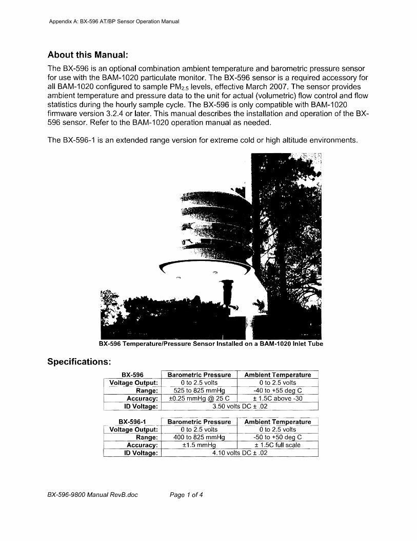
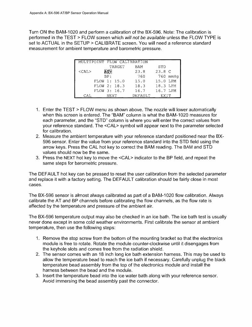
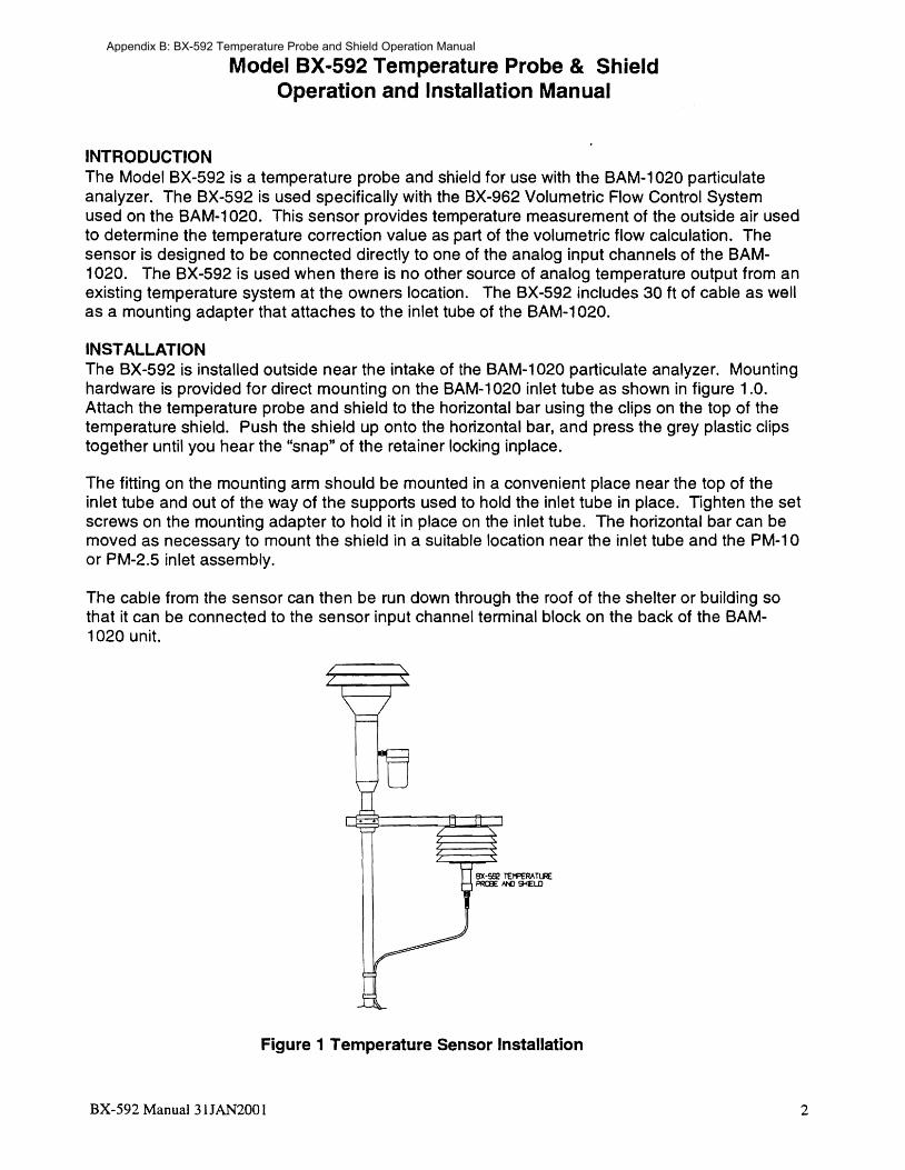
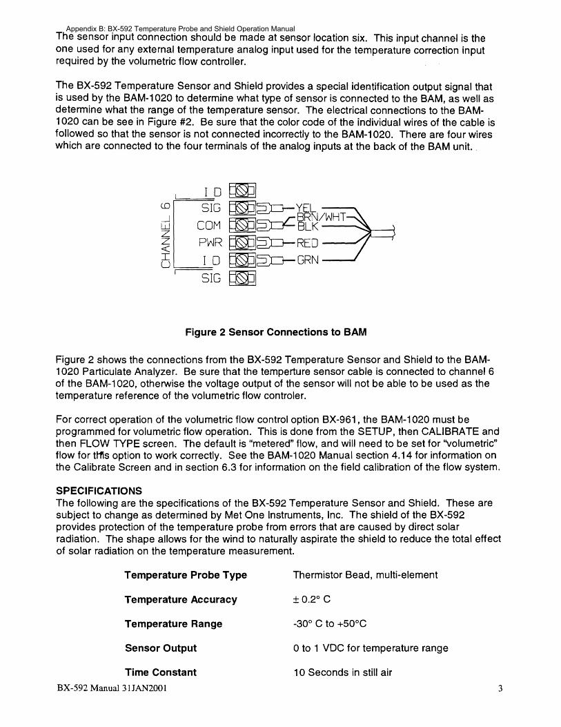
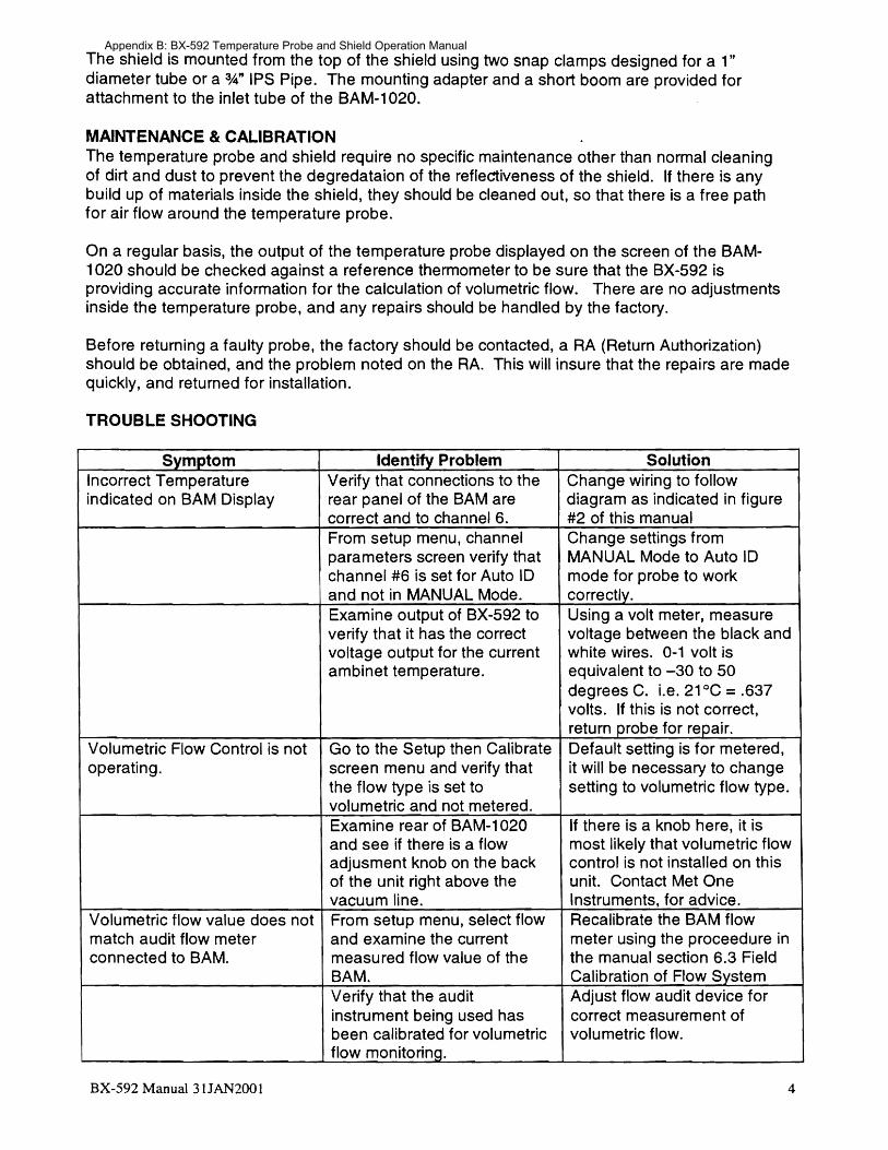
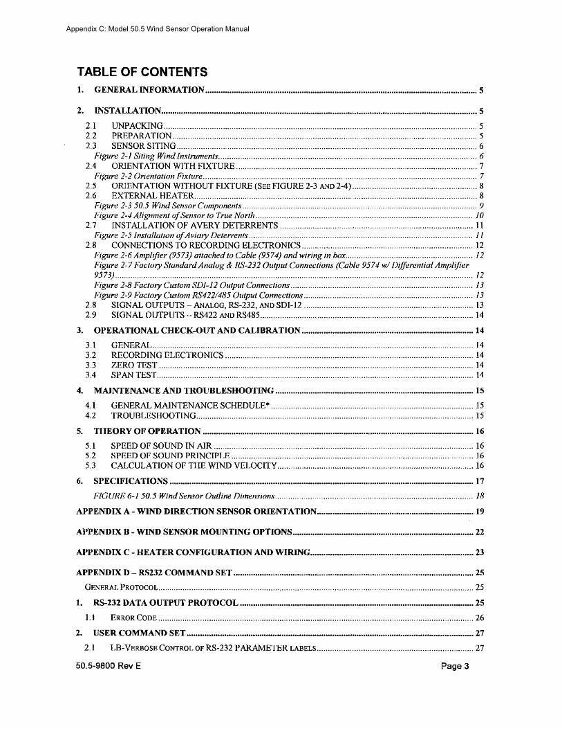
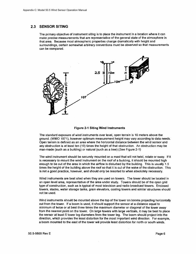
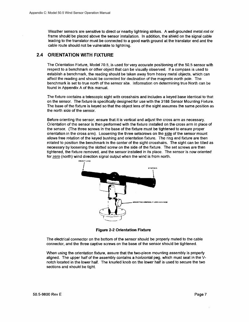
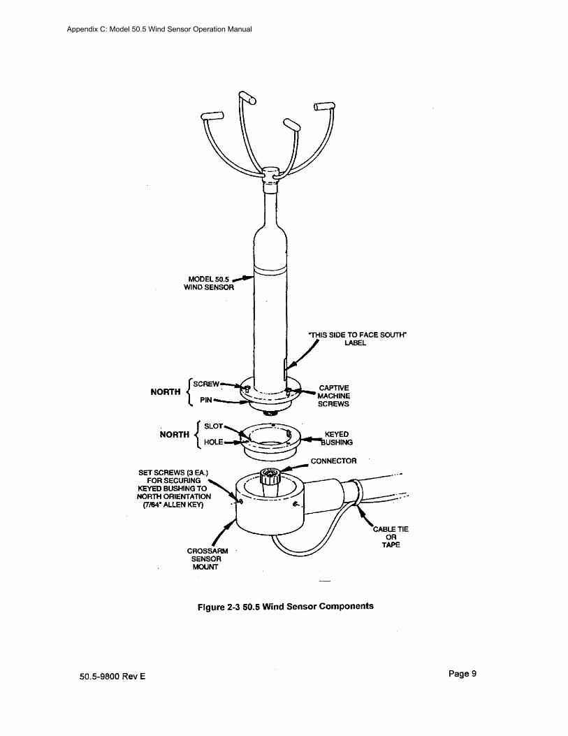
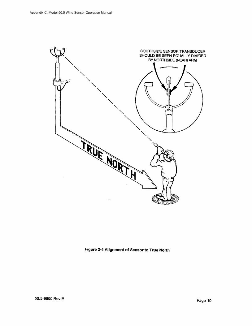
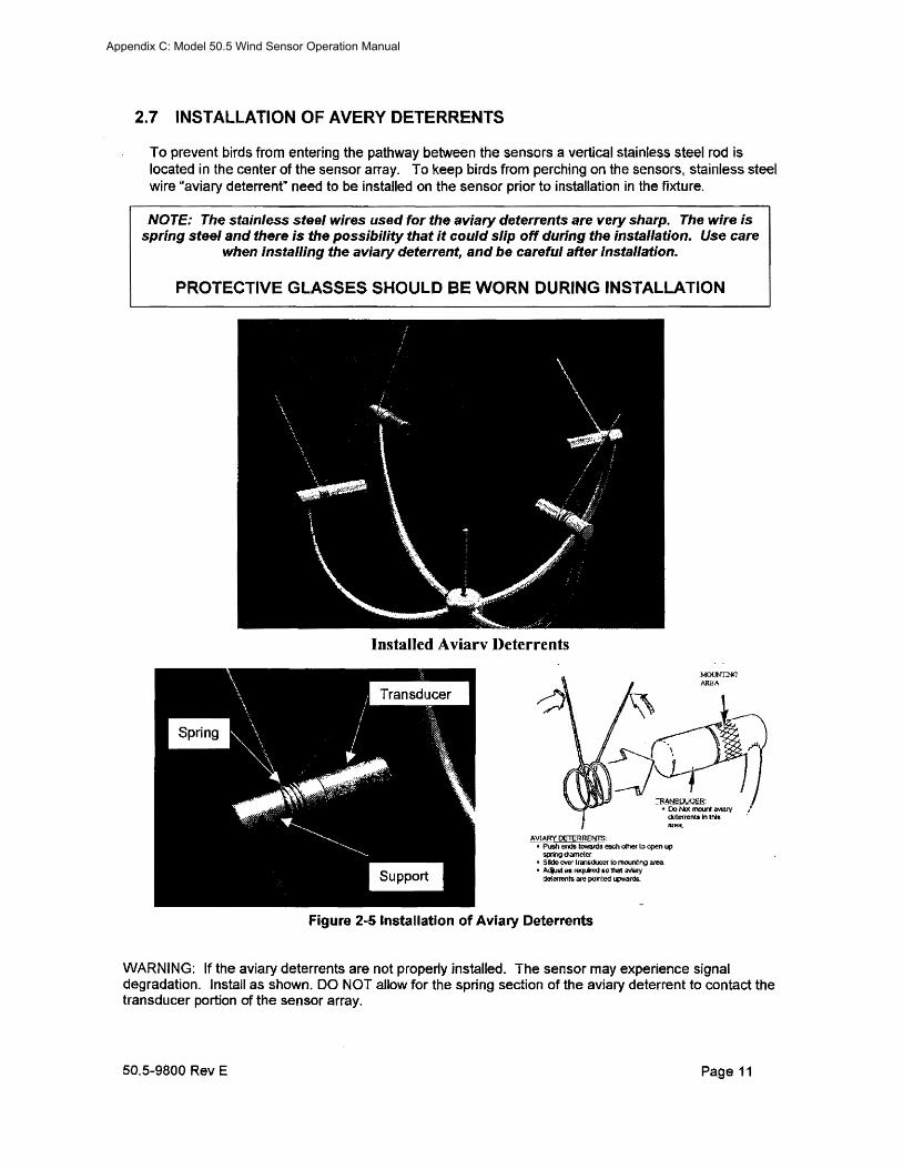
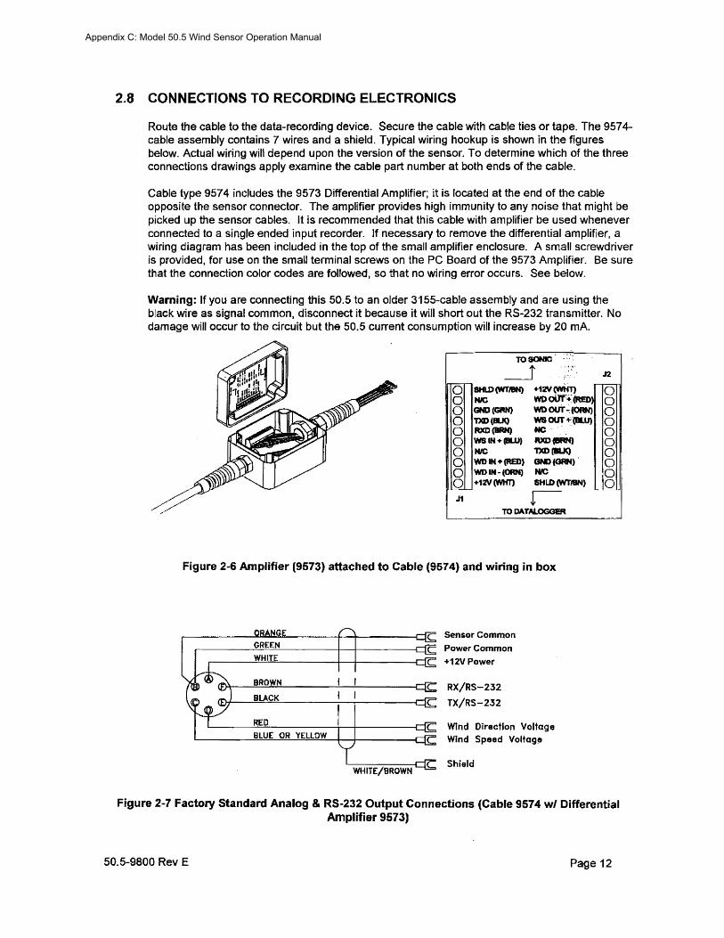
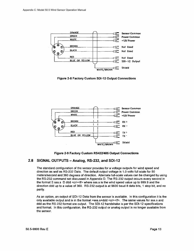
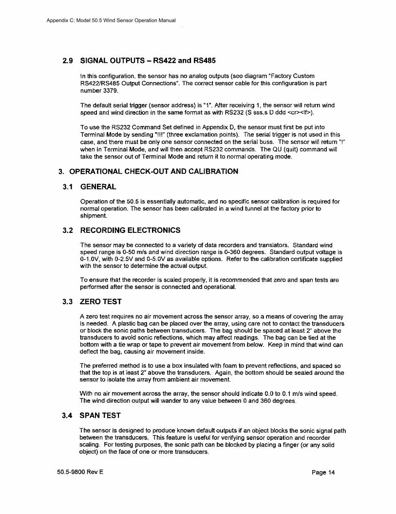
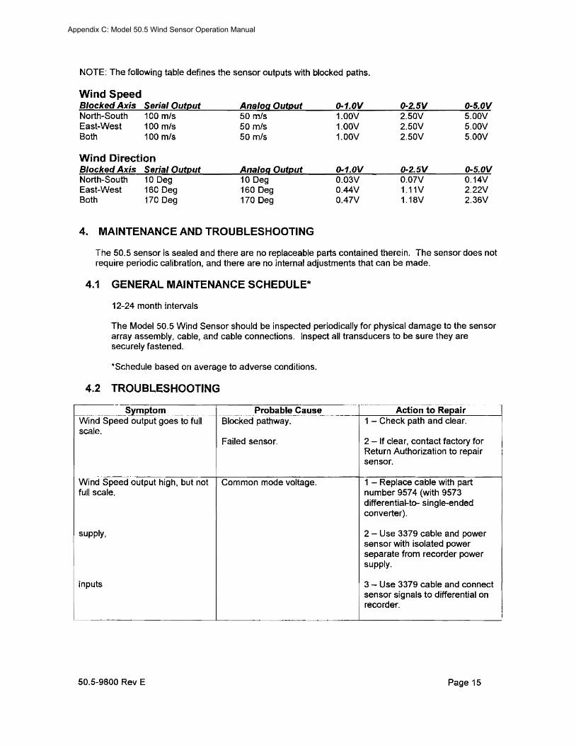
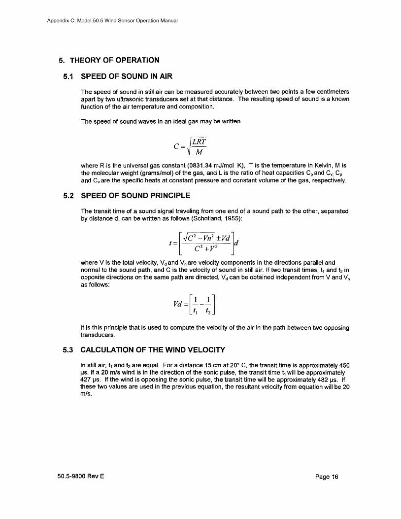
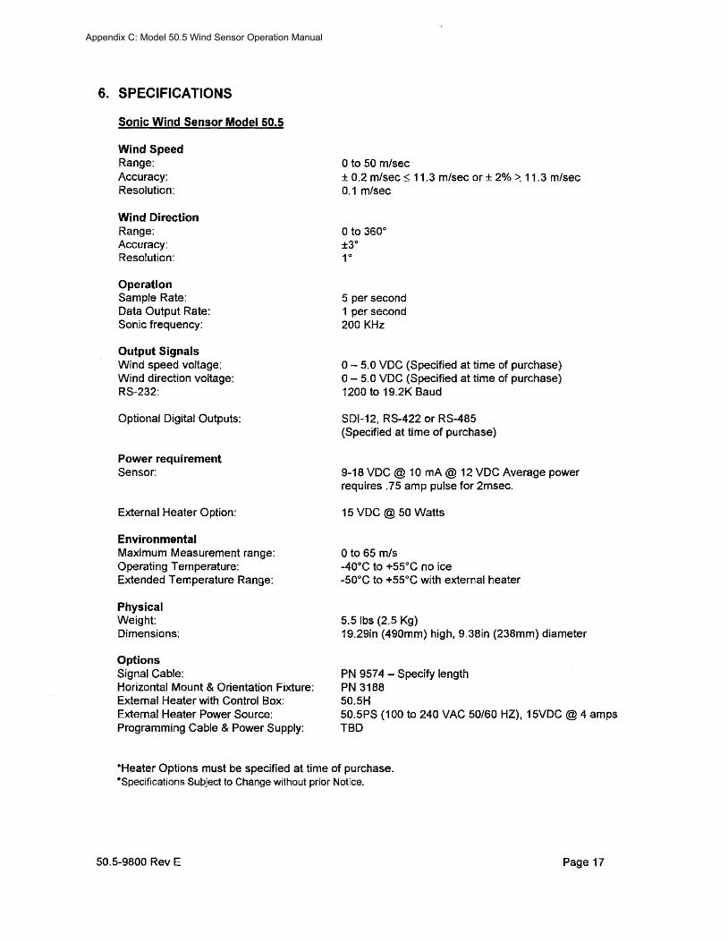
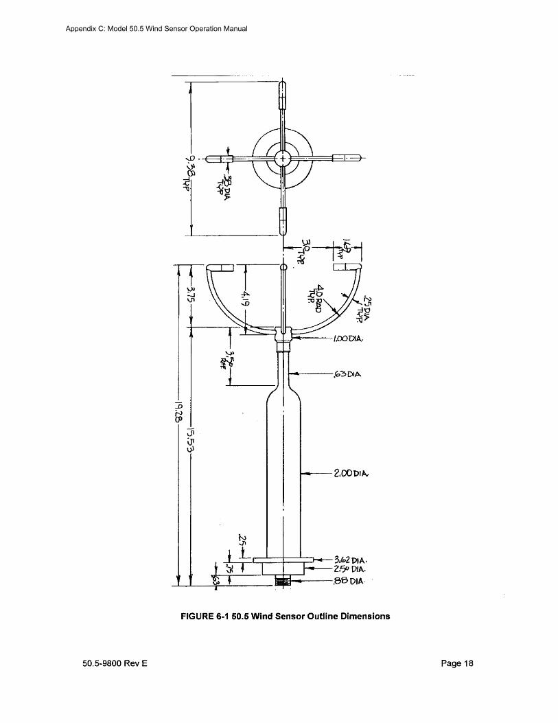
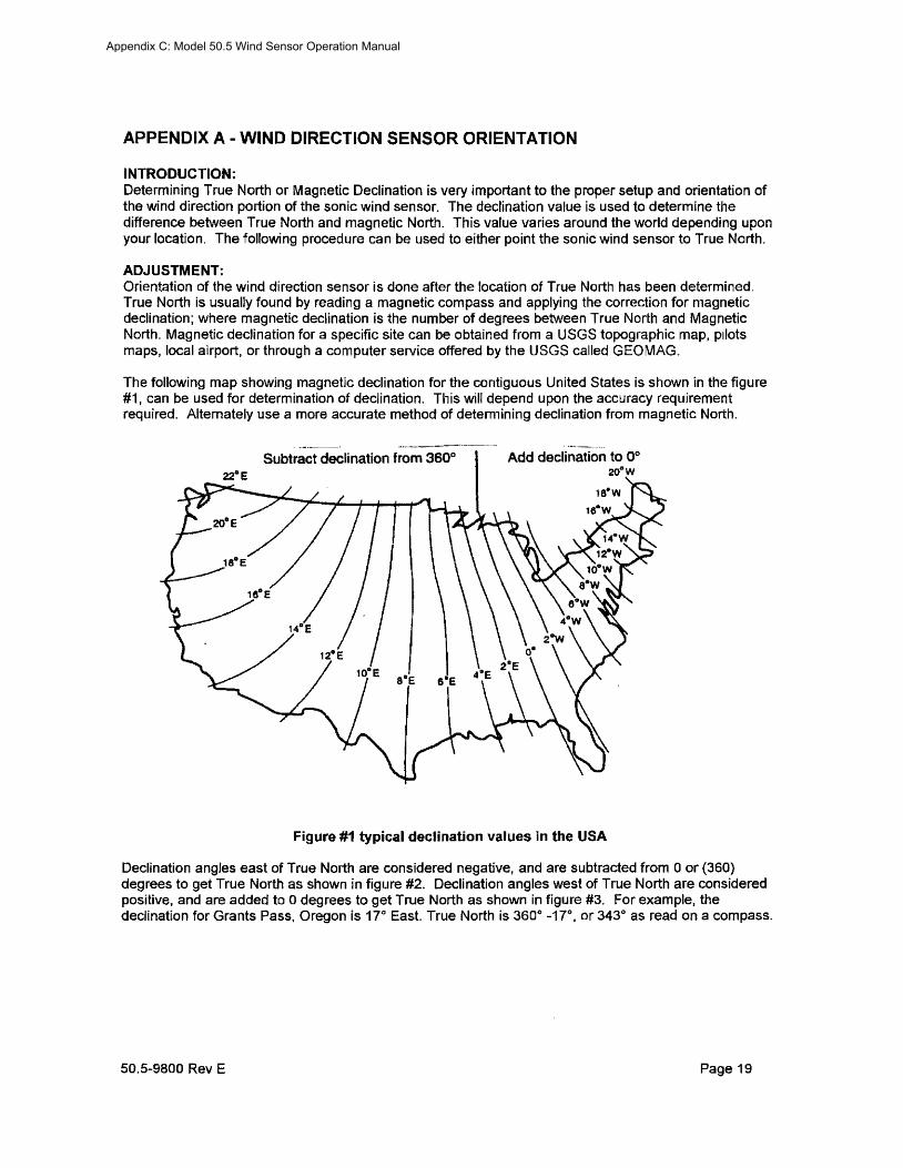
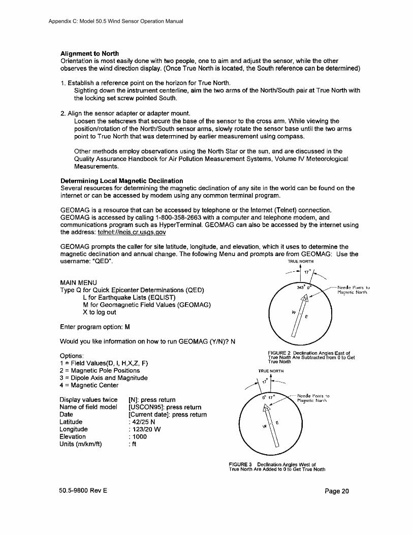
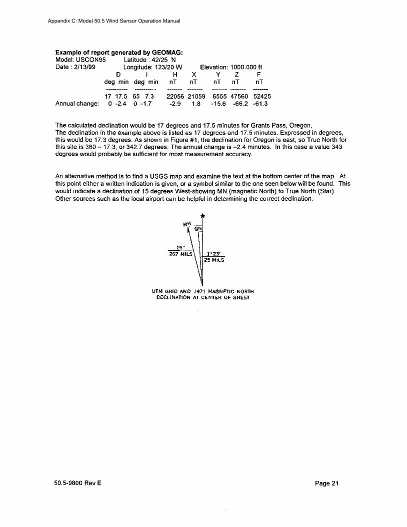
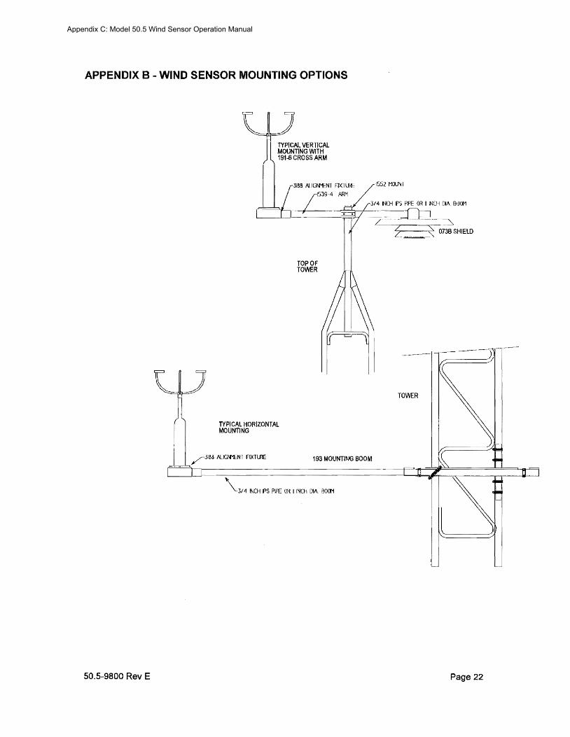
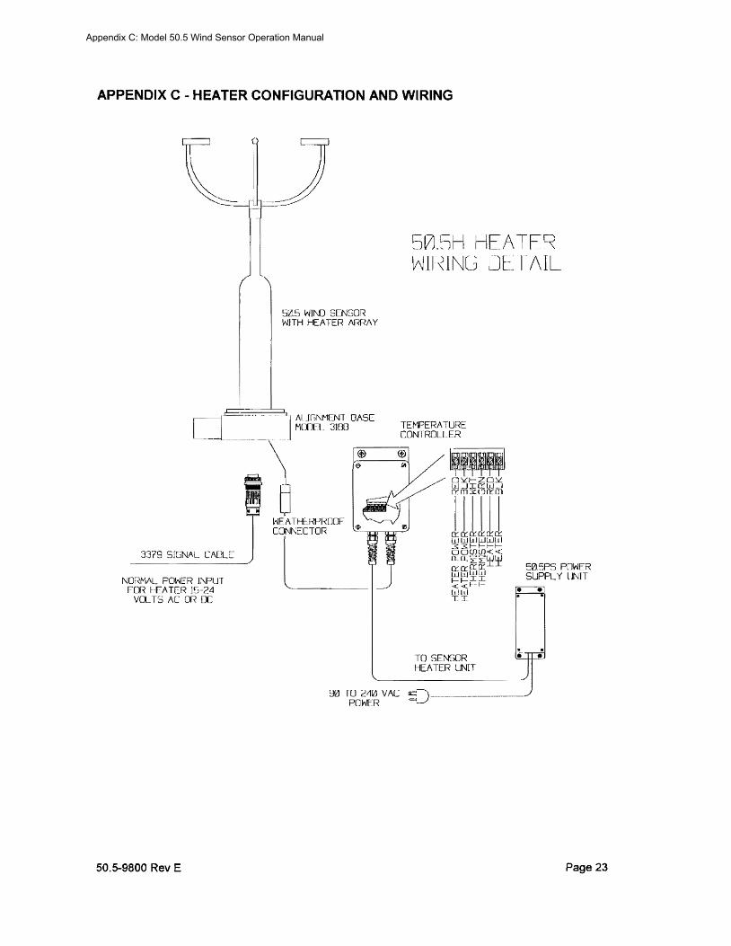
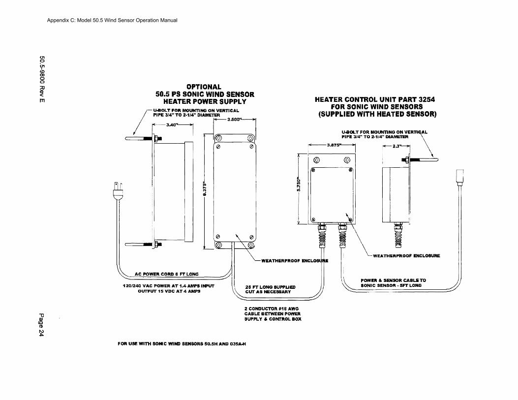
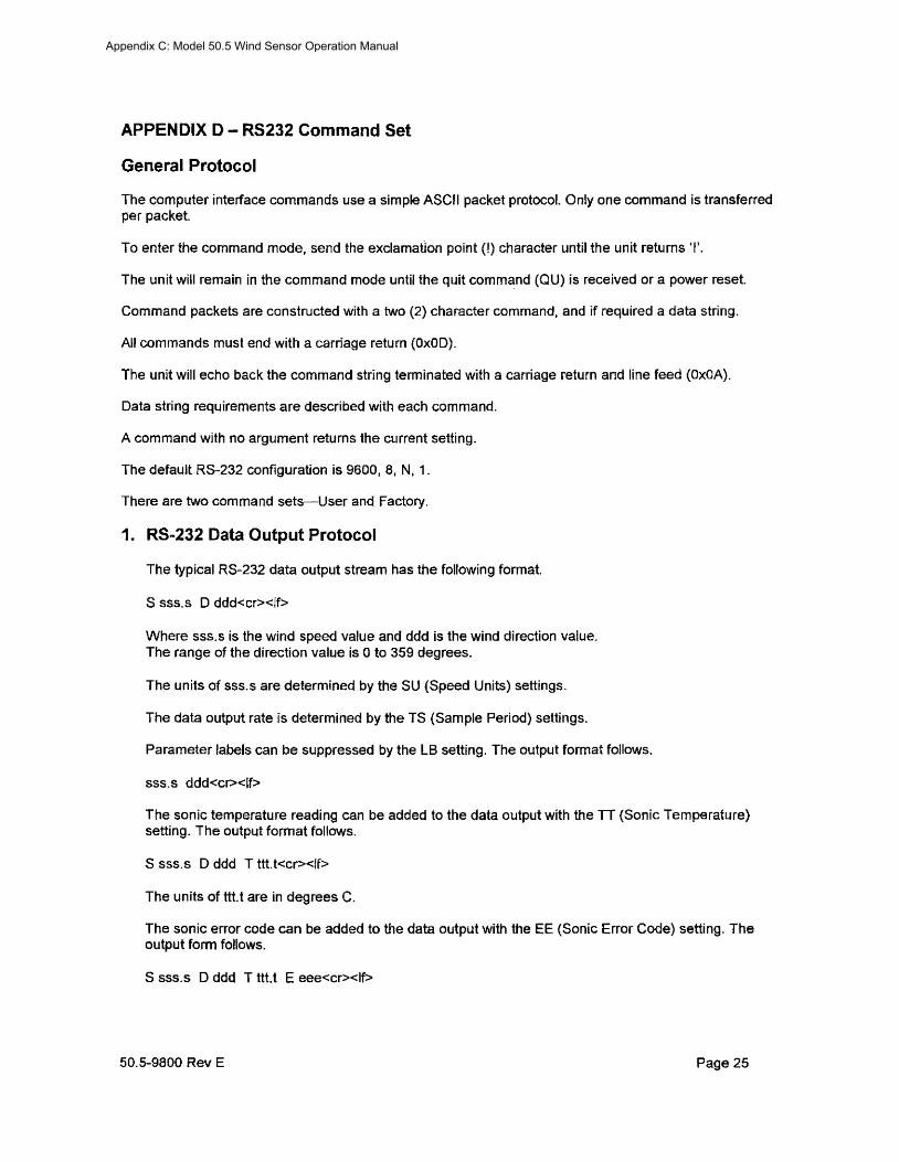
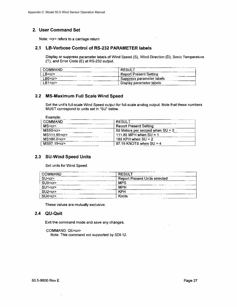
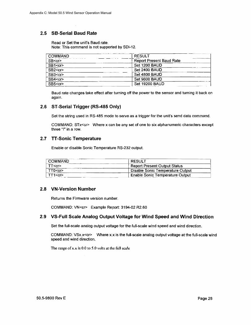
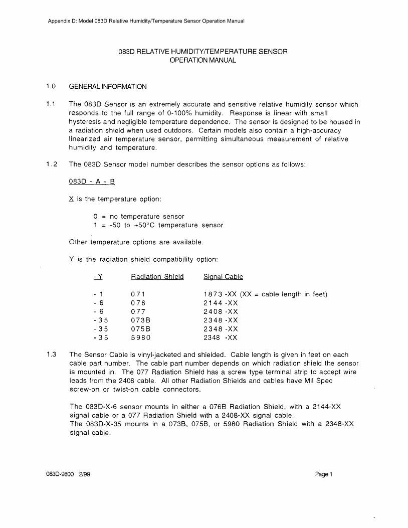
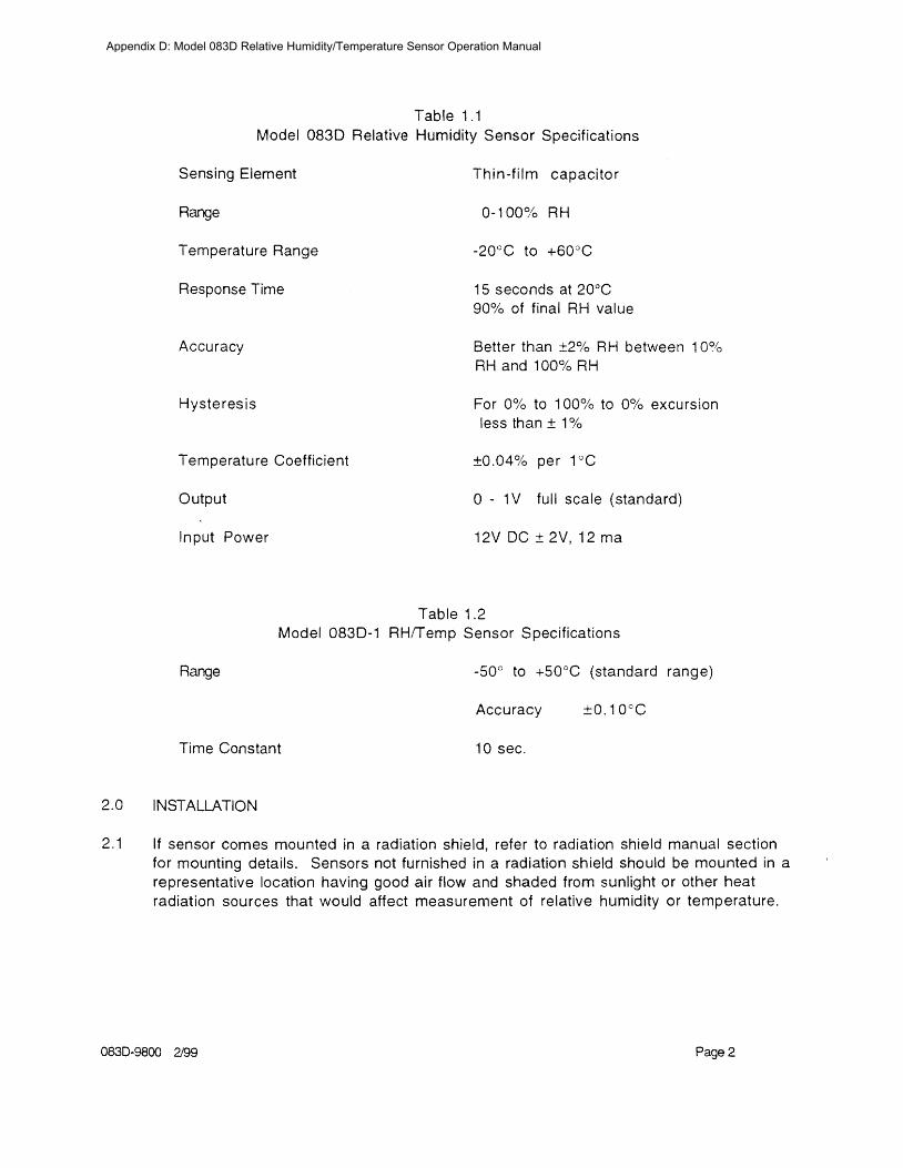
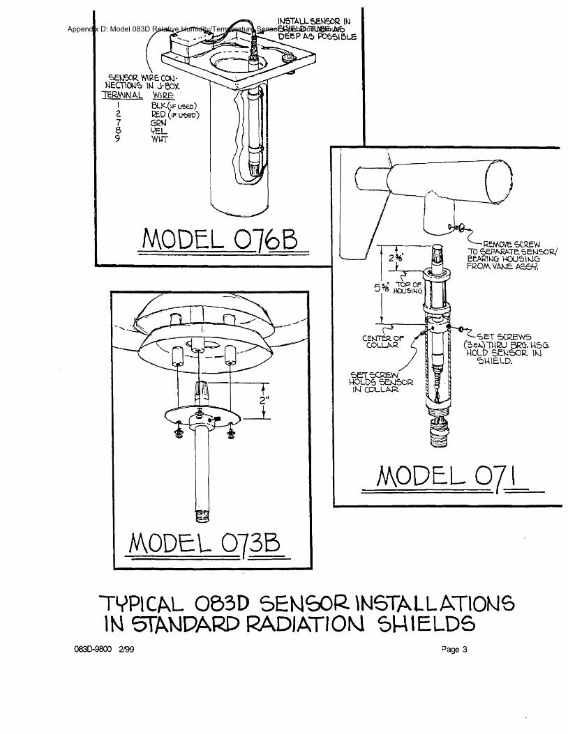
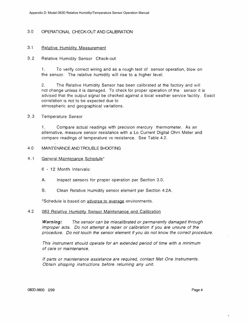
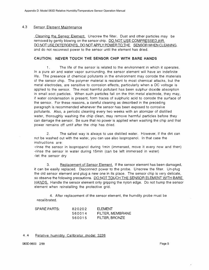
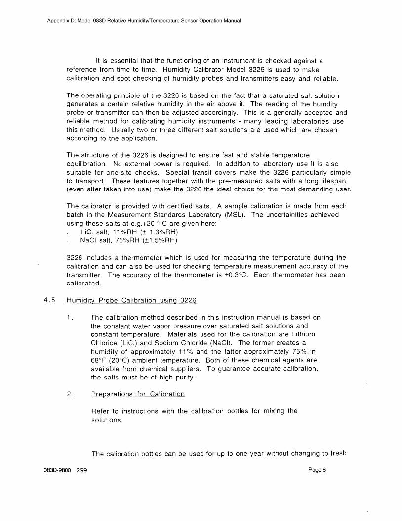
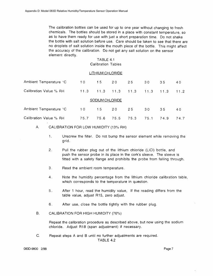
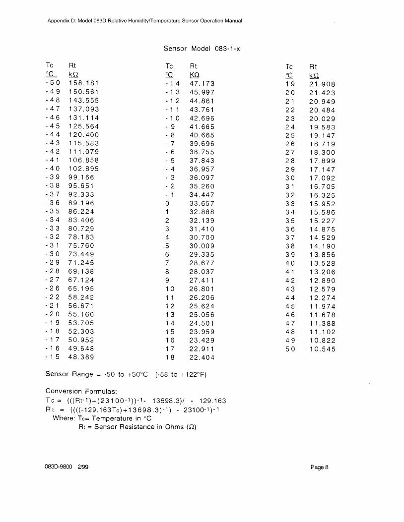
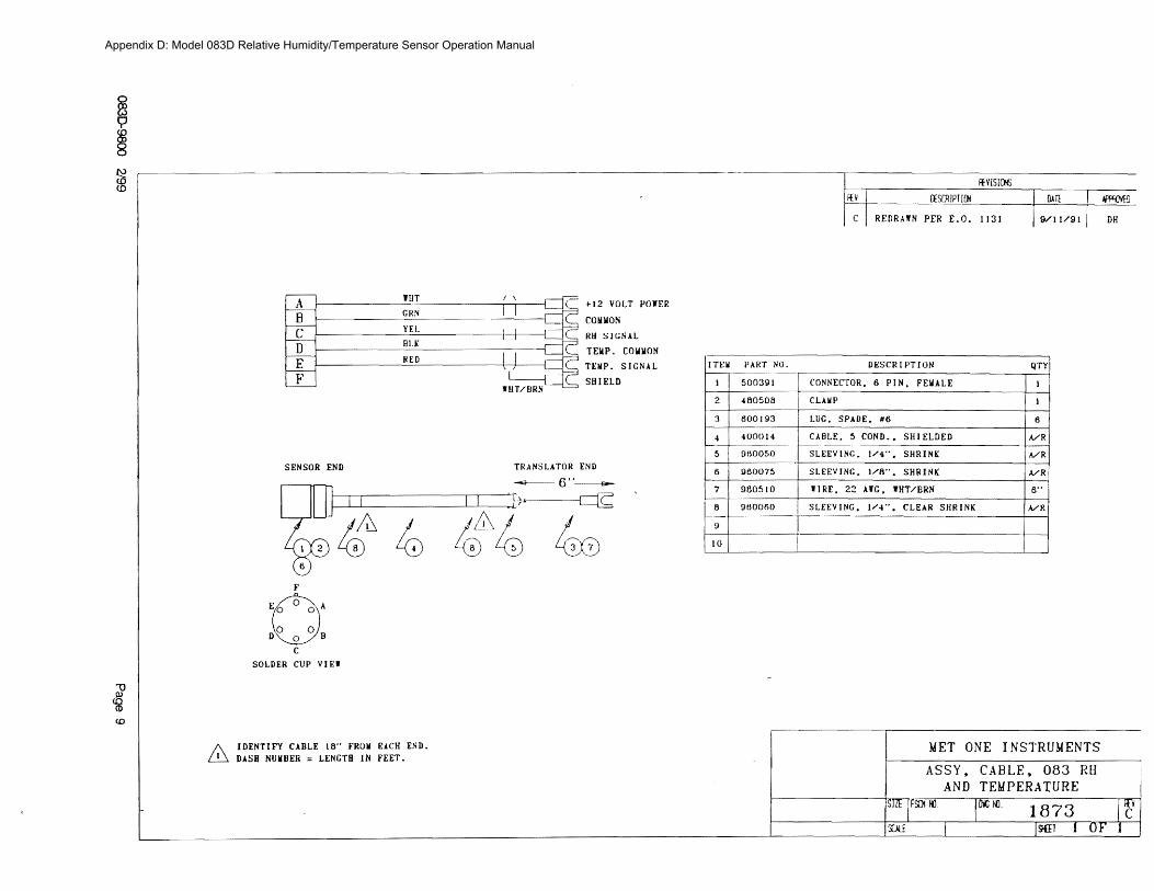
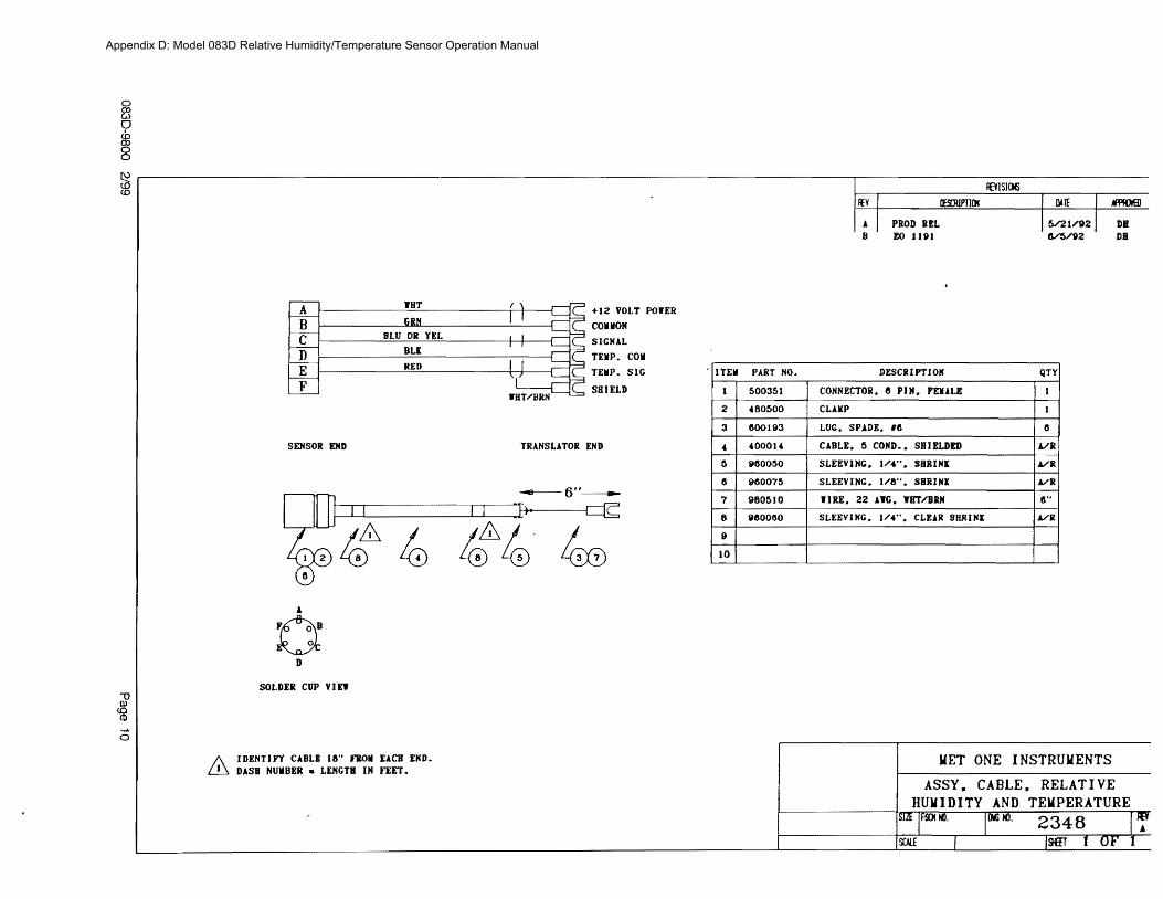
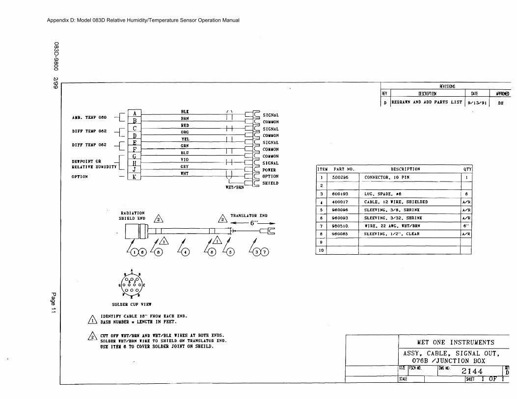
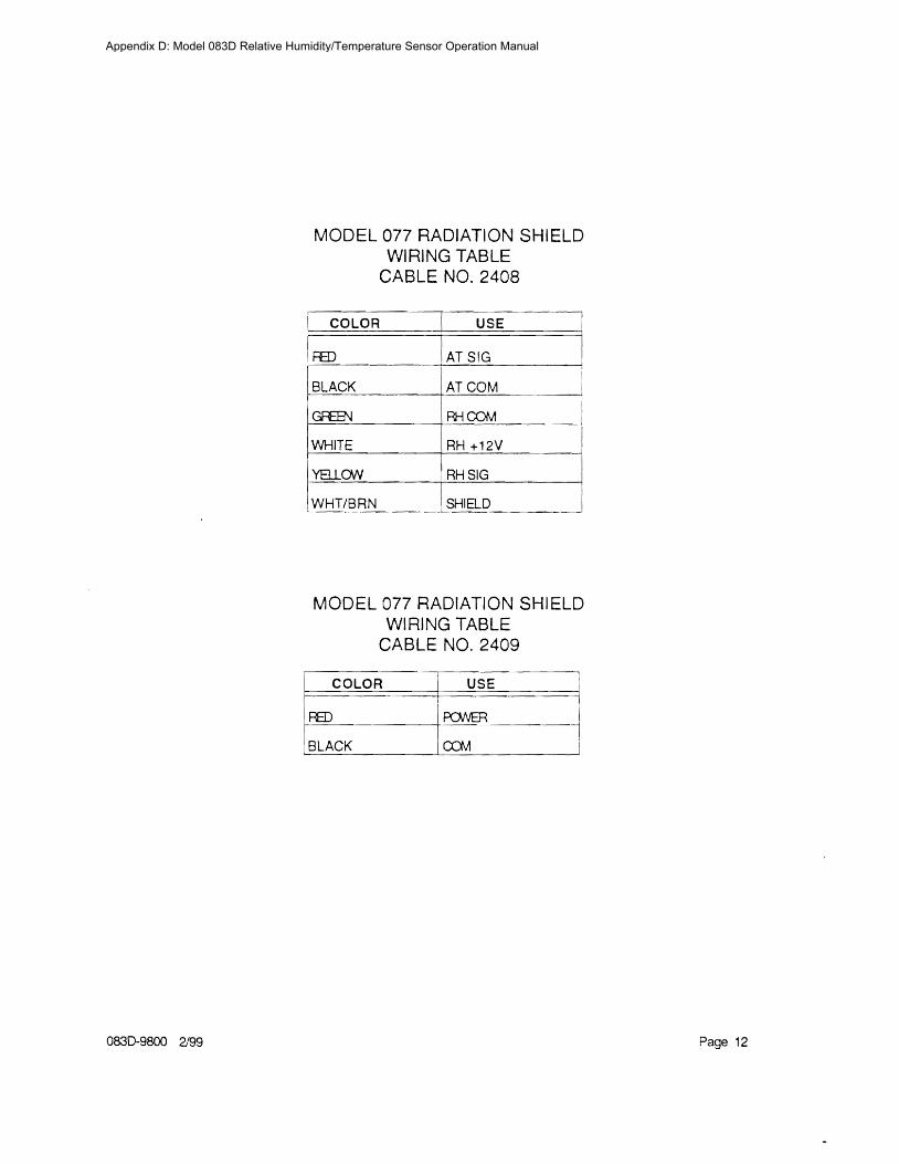
MODEL 077 RADIATION SHIELD WIRING TABLE
CABLE NO 2408
AT COM
RHCOM
NHITE RH +12V
YBLON
MODEL 077 RADIATION SHIELD WIRING TABLE
CABLE NO 2409
0830-9800 299 Page 12
Appendix D Model 083D Relative HumidityTemperature Sensor Operation Manual
090D MANUAL
Appendix E Model 090D Barometric Pressure Operation Manual
Appendix E Model 090D Barometric Pressure Operation Manual
Appendix E Model 090D Barometric Pressure Operation Manual
Appendix E Model 090D Barometric Pressure Operation Manual
Appendix E Model 090D Barometric Pressure Operation Manual
Appendix E Model 090D Barometric Pressure Operation Manual
MODEL 375C 8 RAIN GAUGE
OPERATION MANUAL Document No 375-9801
1600 Washington Blvd Regional Sales amp Service Grants Pass Oregon 97526 3206 Main St Suite 106 Telephone 503-471-7111 Rowlett Texas 75088 Facsimile 503-471-7116 Telephone 214-412-4747
Met One Facsimile 214-412-4716
Instruments
Appendix F Model 375C 8rdquo Rain Gauge Operation Manual
MODEL 375C ELECTRIC RAINSNOW SENSOR
OPERATION MANUAL
10 GENERAL INFORtv1ATION
1 1 Model 375C Electric Heated Tipping Bucket RainSnow Gauge is an accurate sensitive and low-maintenance sensor designed to measure rainfall on a continuous basis Water does not collect in the sensor but is drained each time an internal bucket fills with 001 inch of rainfall (standard calibration) At this time a switch closure pulse is also sent to the translator module for counting The sensor is calibrated prior to shipment and requires no adjustments after mounting
1 2 Sensor Cable is a vinyl-jacketed 2-conductor shielded cable connecting to the sensor via an internal terminal strip Cable length is designated in -xx feet on each cable part number label
13 Power Cable is a vinyl-jacketed 3-conductor shielded cable connecting to the sensor heaters with wire nuts in an externally mounted J-8ox Cable length is designated in shyxx feet on each cable part number label
Table 1-1 Model 375C Rainfall Sensor Specifications
Orifice 8 Diameter
Calibration (standard) 0111 Rain per switch closure Calibration (options) 02mm 025mm
Accuracy plusmn1 at 111 to 3 11 per hour at 70deg F
Switch Type Magnet amp Reed
Mounting 3 Pads for 14 bolts on 9-213211 (966) circle diameter
Dimensions 17-34 high 8 diameter not including mounting pads
Power Requirement 110VAC 5060 Hz 315W
Weight less cables 75 Ibs34 kg (10 Ibs shipping wcables)
375C 894 Page 1
Appendix F Model 375C 8rdquo Rain Gauge Operation Manual
20 INSTALLATION
2 1 Choose a site where the height of any nearby trees or other objects above the sensor is no more than about twice their distance from the sensor (Sample 50 ft tree at least 100 away from gauge) A uniform surrounding of objects (such as an orchard) is beneficial as a wind break Nonuniform surroundings (such as a nearby building) creates turbulence which affects accuracy
22 Mount the sensor ~ on a platform using the built in level as an aid The three legs can be adjusted for leveling Three 14 diameter bolts are used to mount the sensor on a 9-2132 (966) bolt circle
23 Remove shipping restraint (This may be tape rubber band or similar item) from sensor bucket and verify that bucket moves freely and that all adjusting screws are tight
24 Connect the signal cable lugs to the terminal strip if not connected already See diagram Polarity is not important See FIGURE 2-1
25 Connect the power cable to the leads inside the condulet (see FIGURE 2-2) if not connected already
26 Replace cover on sensor tightening screws at base
NOTE If snowfall is anticipated remove primary screen from funnel
27 Route signal cable to the translator or datalogger and connect Refer to the System Interconnect Diagram in your system manual for terminal identification
28 Route the power cable to a 11 OVAC power source protected with a 15A GFI circuit Connect (Ref FIGURE 2-2) This wiring must conform to local and state wiring codes If you are not familiar with these codes an electrical contractor should be used
Warning As with any AC power wiring Improper safety procedures can cause fatal injuries If you are not qualified to do this work call an electrical contractor to do It for you
375C 894 Page 2
Appendix F Model 375C 8rdquo Rain Gauge Operation Manual
BABBlER STRIP
ATTACH SIGNAL CABLE LEADS TO SAME
SIGNAL CABLE
TERMINALS AS REED SWITCH (POLARITY NOT IMPORTANT)
fiGURE 2- 375C 894
Page 3
Appendix F Model 375C 8rdquo Rain Gauge Operation Manual
I
CUSTONER i I
-OOKUP shyr
NttRT6HT~ CABLE --J CLMAP
Y
110 VAc 5cI(cO -f PROTECTED BY
gt~CrFl CJ RCl)lTBREb-KER
~E~TER POWER 400KUP fct 2 - 2
375C 894 Page 4
Appendix F Model 375C 8rdquo Rain Gauge Operation Manual
3 0 OPERATIONAL CHECK-OUT
31 Manually actuate tip bucket mechanism (stop-to-stop) three (3) times Confirm that 3 tips have registered on the recording equipment If not refer to Troubleshooting Guide Section 4-3
4 0 MAINTENANCE AND TROUBLESHOOTING
4 1 General Maintenance Schedule At six month intervals perform the following steps
a Clean sensor funnel and buckets b Do NOT lubricate the pivots as any lubricant may attract dust and dirt and cause
wear of the jewel bearings c Verify that buckets move freely and that translator card or datalogger registers
001 or as calibrated for each bucket tip
Based on average to adverse environments
42 Calibration The sensor is factory calibrated recalibration is not required unless damage has occurred or the adjustment screws have loosened To check or recalibrate perform the following steps
a Check to be sure the sensor is level
b Wet the mechanism and tipping bucket assembly Using a graduated cylinder slowly pour the measured quantity of water through the inner funnel to the tipping bucket which should then tip Repeat for the alternate bucket If both buckets tip when filled with the measured quantity of water the sensor is properly calibrated If they do not recalibrate as follows
1 Release the lock nuts on the cup adjustments 2 Move the adjustment screws down to a position that would place the bucket
far out of calibration 3 Allow the measured quantity of water to enter the bucket (Refer to Table
41) 4 Turn the cup adjustment screw up until the bucket assembly tips Tighten
the lock nut 5 Repeat steps 3 and 4 for the opposite bucket 6 Measure the quantity of water necessary to tip each bucket several times to
ensure proper calibration 7 Replace the cover on the gauge
375C 894 Page 5
Appendix F Model 375C 8rdquo Rain Gauge Operation Manual
Table 41 Calibration Quantities
Tip Calibration Water Quantity
001 (standard) 824 milliliters O2mm 649 milliliters O2Smm 811 milliliters
4 3 TROUBLESHCOTING
SYMPTOM
No sensor output
Erroneous Reading
Snow Not Melting
PROBABL~ CAUSE
Faulty Reed Switch
Signal Cable Connection
Lightning Strike
Debris in Funnel
Sensor not level
Sensor out of Calibration
Site too near trees or other objects
Heaters not getting power
Heater Failure
Primary Screen Installed
REMEDY
Replace Reed Switch
Check Connections
Replace Reed Switch amp Diode
Clean (See 41)
Re-level
iecalibrate (see 42)
Relocate (See 21)
Check circuit protector (customer provided)
Return unit to factory for repair
Remove Screen
375C 894 Page 6
Appendix F Model 375C 8rdquo Rain Gauge Operation Manual
375C 894
Appendix F Model 375C 8rdquo Rain Gauge Operation Manual
RENOYE iP CSNOW S
A~lCl PATED
TO CO~NECTOR
ON BASE ACOSY
~OUSlt1GFUNNEL ASSEMBLY 375C 894 FIGURE 4-3
Appendix F Model 375C 8rdquo Rain Gauge Operation Manual
375C 894 Page 9
Appendix F Model 375C 8rdquo Rain Gauge Operation Manual
44 REPLACEABLE PARTS LIST
Mode 375C Rain Gauge Parts List
10 No Part No
1 2545 2 2492 3 340070 4 480210 5 2598 6 2503 7 480510 8 2934 9 2936 1 0 2937 1 1 1566 1 1 2745 1 2 2504 1 3 2666 4 2516
45 REPAIR AND RECALBRATION SERVICE
Description
Assembly Tip Bucket (01 2mm 25mm) Pin Pivot Barrier Strip - 3 pos Nut Crown Nylon 8-32 Screen Screen Primary Top Clamp Liquid-Tight Reed Switch Cartridge Adjustable Magnet Bracket Lightning Protection Diode Standard Cable Assembly Cable Assembly (for use with Automet) Screen Secondary Assembly HousingFunnel 8 (115VAC) Foot
This service provided by Met One Instruments enables fast economical service for the user This repair and calibration service includes disassembly inspection cleaning reassembly and calibration Components will be replaced as required Additional charges for additional materials only will be added to the basic service charge
375C 894 Page 10
Appendix F Model 375C 8rdquo Rain Gauge Operation Manual
SIIru1
COInWIl
Sil I ElD
SENSOR END TRANSLATOR nw ~ ---- fi f____ -poundltshy~-- G-pound shy
r-= f(--JL 1
I ~--cJ t5(t)
IDENTIFY CABtE lB ROll EACII END D~SIl NUlIllER LENGTi I N FEET
TEll PART NO liE I~ 111 ION QTY
2
LUG SPAUB Rd 5
CABIE 2 IIHE SllIEIDlm -
600193
4[)OIlIO
960050 -~------ ------------------------j
SlnVING 14 SHRINK
7 IllIE 22 AWl iliTurm -------------------------lr--~
8 SLEEV INC 14 CLEAI~ SHRINK
10
MET ONE 1
ASSY CAnLE~ RAIN
Appendix F Model 375C 8rdquo Rain Gauge Operation Manual
SIfNAL
2 I COMMON
3
4
--e-
SENSOR FNO DATALOrCER rND
--=1--- 6
IDENTIFY CAHtE 1(1 FROIl EACH ENDamp DASH HYDER = LENGTH IN FEFT STANDARD lENGTIl = 50 FT
amp STRIP AND TIN WIRE ENDS Imiddot
SOLllEflt CUP VIEW
llFSCltl [ION
-1 PIN FEllAtE
bull 14 SHRINK
4 CLEAR SIIRf HK
MET ONE INSTRUMENTS
ASSY~ CADLE RAIN GAUGE
Appendix F Model 375C 8rdquo Rain Gauge Operation Manual
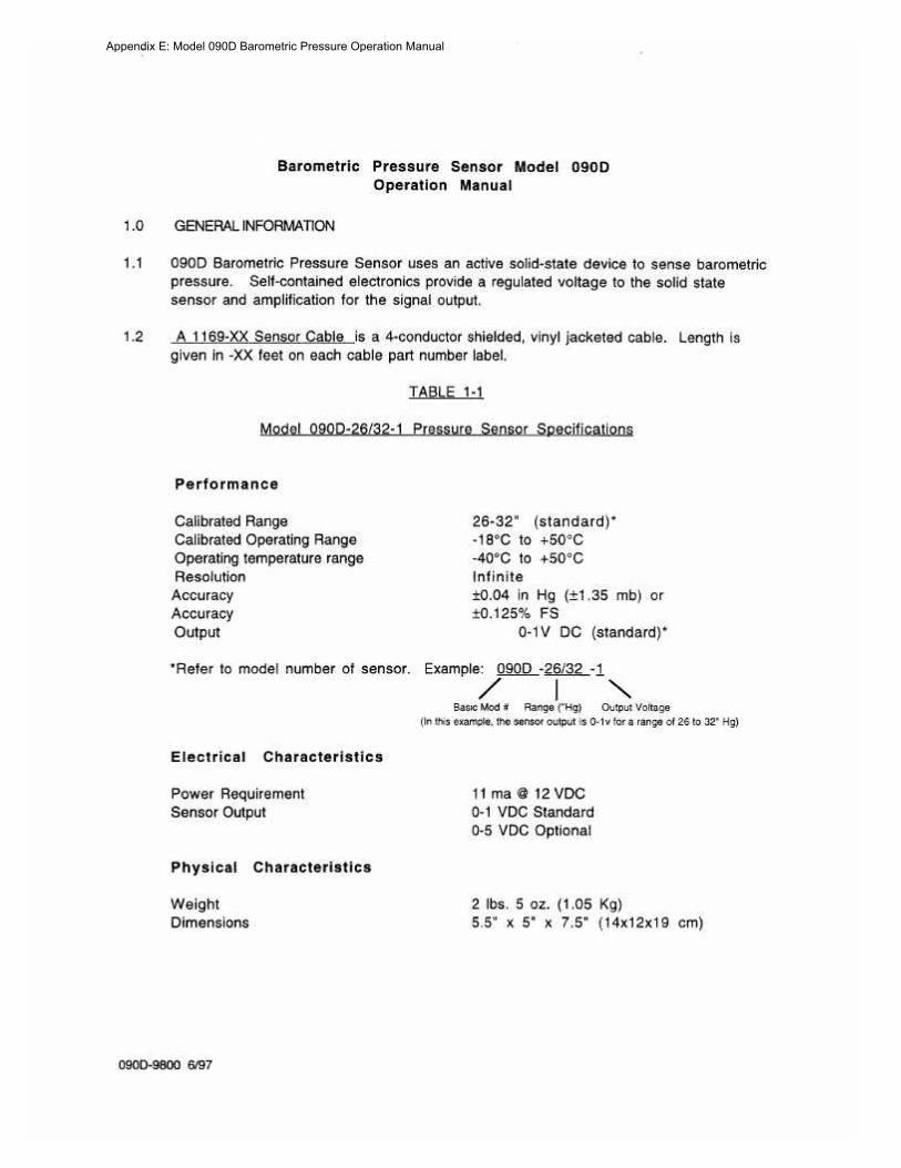
Appendix E Model 090D Barometric Pressure Operation Manual
Appendix E Model 090D Barometric Pressure Operation Manual
Appendix E Model 090D Barometric Pressure Operation Manual
Appendix E Model 090D Barometric Pressure Operation Manual
Appendix E Model 090D Barometric Pressure Operation Manual
MODEL 375C 8 RAIN GAUGE
OPERATION MANUAL Document No 375-9801
1600 Washington Blvd Regional Sales amp Service Grants Pass Oregon 97526 3206 Main St Suite 106 Telephone 503-471-7111 Rowlett Texas 75088 Facsimile 503-471-7116 Telephone 214-412-4747
Met One Facsimile 214-412-4716
Instruments
Appendix F Model 375C 8rdquo Rain Gauge Operation Manual
MODEL 375C ELECTRIC RAINSNOW SENSOR
OPERATION MANUAL
10 GENERAL INFORtv1ATION
1 1 Model 375C Electric Heated Tipping Bucket RainSnow Gauge is an accurate sensitive and low-maintenance sensor designed to measure rainfall on a continuous basis Water does not collect in the sensor but is drained each time an internal bucket fills with 001 inch of rainfall (standard calibration) At this time a switch closure pulse is also sent to the translator module for counting The sensor is calibrated prior to shipment and requires no adjustments after mounting
1 2 Sensor Cable is a vinyl-jacketed 2-conductor shielded cable connecting to the sensor via an internal terminal strip Cable length is designated in -xx feet on each cable part number label
13 Power Cable is a vinyl-jacketed 3-conductor shielded cable connecting to the sensor heaters with wire nuts in an externally mounted J-8ox Cable length is designated in shyxx feet on each cable part number label
Table 1-1 Model 375C Rainfall Sensor Specifications
Orifice 8 Diameter
Calibration (standard) 0111 Rain per switch closure Calibration (options) 02mm 025mm
Accuracy plusmn1 at 111 to 3 11 per hour at 70deg F
Switch Type Magnet amp Reed
Mounting 3 Pads for 14 bolts on 9-213211 (966) circle diameter
Dimensions 17-34 high 8 diameter not including mounting pads
Power Requirement 110VAC 5060 Hz 315W
Weight less cables 75 Ibs34 kg (10 Ibs shipping wcables)
375C 894 Page 1
Appendix F Model 375C 8rdquo Rain Gauge Operation Manual
20 INSTALLATION
2 1 Choose a site where the height of any nearby trees or other objects above the sensor is no more than about twice their distance from the sensor (Sample 50 ft tree at least 100 away from gauge) A uniform surrounding of objects (such as an orchard) is beneficial as a wind break Nonuniform surroundings (such as a nearby building) creates turbulence which affects accuracy
22 Mount the sensor ~ on a platform using the built in level as an aid The three legs can be adjusted for leveling Three 14 diameter bolts are used to mount the sensor on a 9-2132 (966) bolt circle
23 Remove shipping restraint (This may be tape rubber band or similar item) from sensor bucket and verify that bucket moves freely and that all adjusting screws are tight
24 Connect the signal cable lugs to the terminal strip if not connected already See diagram Polarity is not important See FIGURE 2-1
25 Connect the power cable to the leads inside the condulet (see FIGURE 2-2) if not connected already
26 Replace cover on sensor tightening screws at base
NOTE If snowfall is anticipated remove primary screen from funnel
27 Route signal cable to the translator or datalogger and connect Refer to the System Interconnect Diagram in your system manual for terminal identification
28 Route the power cable to a 11 OVAC power source protected with a 15A GFI circuit Connect (Ref FIGURE 2-2) This wiring must conform to local and state wiring codes If you are not familiar with these codes an electrical contractor should be used
Warning As with any AC power wiring Improper safety procedures can cause fatal injuries If you are not qualified to do this work call an electrical contractor to do It for you
375C 894 Page 2
Appendix F Model 375C 8rdquo Rain Gauge Operation Manual
BABBlER STRIP
ATTACH SIGNAL CABLE LEADS TO SAME
SIGNAL CABLE
TERMINALS AS REED SWITCH (POLARITY NOT IMPORTANT)
fiGURE 2- 375C 894
Page 3
Appendix F Model 375C 8rdquo Rain Gauge Operation Manual
I
CUSTONER i I
-OOKUP shyr
NttRT6HT~ CABLE --J CLMAP
Y
110 VAc 5cI(cO -f PROTECTED BY
gt~CrFl CJ RCl)lTBREb-KER
~E~TER POWER 400KUP fct 2 - 2
375C 894 Page 4
Appendix F Model 375C 8rdquo Rain Gauge Operation Manual
3 0 OPERATIONAL CHECK-OUT
31 Manually actuate tip bucket mechanism (stop-to-stop) three (3) times Confirm that 3 tips have registered on the recording equipment If not refer to Troubleshooting Guide Section 4-3
4 0 MAINTENANCE AND TROUBLESHOOTING
4 1 General Maintenance Schedule At six month intervals perform the following steps
a Clean sensor funnel and buckets b Do NOT lubricate the pivots as any lubricant may attract dust and dirt and cause
wear of the jewel bearings c Verify that buckets move freely and that translator card or datalogger registers
001 or as calibrated for each bucket tip
Based on average to adverse environments
42 Calibration The sensor is factory calibrated recalibration is not required unless damage has occurred or the adjustment screws have loosened To check or recalibrate perform the following steps
a Check to be sure the sensor is level
b Wet the mechanism and tipping bucket assembly Using a graduated cylinder slowly pour the measured quantity of water through the inner funnel to the tipping bucket which should then tip Repeat for the alternate bucket If both buckets tip when filled with the measured quantity of water the sensor is properly calibrated If they do not recalibrate as follows
1 Release the lock nuts on the cup adjustments 2 Move the adjustment screws down to a position that would place the bucket
far out of calibration 3 Allow the measured quantity of water to enter the bucket (Refer to Table
41) 4 Turn the cup adjustment screw up until the bucket assembly tips Tighten
the lock nut 5 Repeat steps 3 and 4 for the opposite bucket 6 Measure the quantity of water necessary to tip each bucket several times to
ensure proper calibration 7 Replace the cover on the gauge
375C 894 Page 5
Appendix F Model 375C 8rdquo Rain Gauge Operation Manual
Table 41 Calibration Quantities
Tip Calibration Water Quantity
001 (standard) 824 milliliters O2mm 649 milliliters O2Smm 811 milliliters
4 3 TROUBLESHCOTING
SYMPTOM
No sensor output
Erroneous Reading
Snow Not Melting
PROBABL~ CAUSE
Faulty Reed Switch
Signal Cable Connection
Lightning Strike
Debris in Funnel
Sensor not level
Sensor out of Calibration
Site too near trees or other objects
Heaters not getting power
Heater Failure
Primary Screen Installed
REMEDY
Replace Reed Switch
Check Connections
Replace Reed Switch amp Diode
Clean (See 41)
Re-level
iecalibrate (see 42)
Relocate (See 21)
Check circuit protector (customer provided)
Return unit to factory for repair
Remove Screen
375C 894 Page 6
Appendix F Model 375C 8rdquo Rain Gauge Operation Manual
375C 894
Appendix F Model 375C 8rdquo Rain Gauge Operation Manual
RENOYE iP CSNOW S
A~lCl PATED
TO CO~NECTOR
ON BASE ACOSY
~OUSlt1GFUNNEL ASSEMBLY 375C 894 FIGURE 4-3
Appendix F Model 375C 8rdquo Rain Gauge Operation Manual
375C 894 Page 9
Appendix F Model 375C 8rdquo Rain Gauge Operation Manual
44 REPLACEABLE PARTS LIST
Mode 375C Rain Gauge Parts List
10 No Part No
1 2545 2 2492 3 340070 4 480210 5 2598 6 2503 7 480510 8 2934 9 2936 1 0 2937 1 1 1566 1 1 2745 1 2 2504 1 3 2666 4 2516
45 REPAIR AND RECALBRATION SERVICE
Description
Assembly Tip Bucket (01 2mm 25mm) Pin Pivot Barrier Strip - 3 pos Nut Crown Nylon 8-32 Screen Screen Primary Top Clamp Liquid-Tight Reed Switch Cartridge Adjustable Magnet Bracket Lightning Protection Diode Standard Cable Assembly Cable Assembly (for use with Automet) Screen Secondary Assembly HousingFunnel 8 (115VAC) Foot
This service provided by Met One Instruments enables fast economical service for the user This repair and calibration service includes disassembly inspection cleaning reassembly and calibration Components will be replaced as required Additional charges for additional materials only will be added to the basic service charge
375C 894 Page 10
Appendix F Model 375C 8rdquo Rain Gauge Operation Manual
SIIru1
COInWIl
Sil I ElD
SENSOR END TRANSLATOR nw ~ ---- fi f____ -poundltshy~-- G-pound shy
r-= f(--JL 1
I ~--cJ t5(t)
IDENTIFY CABtE lB ROll EACII END D~SIl NUlIllER LENGTi I N FEET
TEll PART NO liE I~ 111 ION QTY
2
LUG SPAUB Rd 5
CABIE 2 IIHE SllIEIDlm -
600193
4[)OIlIO
960050 -~------ ------------------------j
SlnVING 14 SHRINK
7 IllIE 22 AWl iliTurm -------------------------lr--~
8 SLEEV INC 14 CLEAI~ SHRINK
10
MET ONE 1
ASSY CAnLE~ RAIN
Appendix F Model 375C 8rdquo Rain Gauge Operation Manual
SIfNAL
2 I COMMON
3
4
--e-
SENSOR FNO DATALOrCER rND
--=1--- 6
IDENTIFY CAHtE 1(1 FROIl EACH ENDamp DASH HYDER = LENGTH IN FEFT STANDARD lENGTIl = 50 FT
amp STRIP AND TIN WIRE ENDS Imiddot
SOLllEflt CUP VIEW
llFSCltl [ION
-1 PIN FEllAtE
bull 14 SHRINK
4 CLEAR SIIRf HK
MET ONE INSTRUMENTS
ASSY~ CADLE RAIN GAUGE
Appendix F Model 375C 8rdquo Rain Gauge Operation Manual
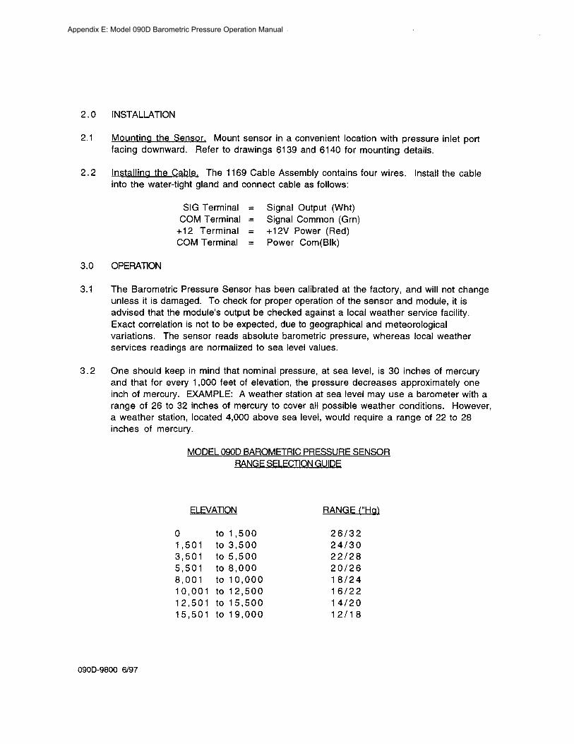
Appendix E Model 090D Barometric Pressure Operation Manual
Appendix E Model 090D Barometric Pressure Operation Manual
Appendix E Model 090D Barometric Pressure Operation Manual
Appendix E Model 090D Barometric Pressure Operation Manual
MODEL 375C 8 RAIN GAUGE
OPERATION MANUAL Document No 375-9801
1600 Washington Blvd Regional Sales amp Service Grants Pass Oregon 97526 3206 Main St Suite 106 Telephone 503-471-7111 Rowlett Texas 75088 Facsimile 503-471-7116 Telephone 214-412-4747
Met One Facsimile 214-412-4716
Instruments
Appendix F Model 375C 8rdquo Rain Gauge Operation Manual
MODEL 375C ELECTRIC RAINSNOW SENSOR
OPERATION MANUAL
10 GENERAL INFORtv1ATION
1 1 Model 375C Electric Heated Tipping Bucket RainSnow Gauge is an accurate sensitive and low-maintenance sensor designed to measure rainfall on a continuous basis Water does not collect in the sensor but is drained each time an internal bucket fills with 001 inch of rainfall (standard calibration) At this time a switch closure pulse is also sent to the translator module for counting The sensor is calibrated prior to shipment and requires no adjustments after mounting
1 2 Sensor Cable is a vinyl-jacketed 2-conductor shielded cable connecting to the sensor via an internal terminal strip Cable length is designated in -xx feet on each cable part number label
13 Power Cable is a vinyl-jacketed 3-conductor shielded cable connecting to the sensor heaters with wire nuts in an externally mounted J-8ox Cable length is designated in shyxx feet on each cable part number label
Table 1-1 Model 375C Rainfall Sensor Specifications
Orifice 8 Diameter
Calibration (standard) 0111 Rain per switch closure Calibration (options) 02mm 025mm
Accuracy plusmn1 at 111 to 3 11 per hour at 70deg F
Switch Type Magnet amp Reed
Mounting 3 Pads for 14 bolts on 9-213211 (966) circle diameter
Dimensions 17-34 high 8 diameter not including mounting pads
Power Requirement 110VAC 5060 Hz 315W
Weight less cables 75 Ibs34 kg (10 Ibs shipping wcables)
375C 894 Page 1
Appendix F Model 375C 8rdquo Rain Gauge Operation Manual
20 INSTALLATION
2 1 Choose a site where the height of any nearby trees or other objects above the sensor is no more than about twice their distance from the sensor (Sample 50 ft tree at least 100 away from gauge) A uniform surrounding of objects (such as an orchard) is beneficial as a wind break Nonuniform surroundings (such as a nearby building) creates turbulence which affects accuracy
22 Mount the sensor ~ on a platform using the built in level as an aid The three legs can be adjusted for leveling Three 14 diameter bolts are used to mount the sensor on a 9-2132 (966) bolt circle
23 Remove shipping restraint (This may be tape rubber band or similar item) from sensor bucket and verify that bucket moves freely and that all adjusting screws are tight
24 Connect the signal cable lugs to the terminal strip if not connected already See diagram Polarity is not important See FIGURE 2-1
25 Connect the power cable to the leads inside the condulet (see FIGURE 2-2) if not connected already
26 Replace cover on sensor tightening screws at base
NOTE If snowfall is anticipated remove primary screen from funnel
27 Route signal cable to the translator or datalogger and connect Refer to the System Interconnect Diagram in your system manual for terminal identification
28 Route the power cable to a 11 OVAC power source protected with a 15A GFI circuit Connect (Ref FIGURE 2-2) This wiring must conform to local and state wiring codes If you are not familiar with these codes an electrical contractor should be used
Warning As with any AC power wiring Improper safety procedures can cause fatal injuries If you are not qualified to do this work call an electrical contractor to do It for you
375C 894 Page 2
Appendix F Model 375C 8rdquo Rain Gauge Operation Manual
BABBlER STRIP
ATTACH SIGNAL CABLE LEADS TO SAME
SIGNAL CABLE
TERMINALS AS REED SWITCH (POLARITY NOT IMPORTANT)
fiGURE 2- 375C 894
Page 3
Appendix F Model 375C 8rdquo Rain Gauge Operation Manual
I
CUSTONER i I
-OOKUP shyr
NttRT6HT~ CABLE --J CLMAP
Y
110 VAc 5cI(cO -f PROTECTED BY
gt~CrFl CJ RCl)lTBREb-KER
~E~TER POWER 400KUP fct 2 - 2
375C 894 Page 4
Appendix F Model 375C 8rdquo Rain Gauge Operation Manual
3 0 OPERATIONAL CHECK-OUT
31 Manually actuate tip bucket mechanism (stop-to-stop) three (3) times Confirm that 3 tips have registered on the recording equipment If not refer to Troubleshooting Guide Section 4-3
4 0 MAINTENANCE AND TROUBLESHOOTING
4 1 General Maintenance Schedule At six month intervals perform the following steps
a Clean sensor funnel and buckets b Do NOT lubricate the pivots as any lubricant may attract dust and dirt and cause
wear of the jewel bearings c Verify that buckets move freely and that translator card or datalogger registers
001 or as calibrated for each bucket tip
Based on average to adverse environments
42 Calibration The sensor is factory calibrated recalibration is not required unless damage has occurred or the adjustment screws have loosened To check or recalibrate perform the following steps
a Check to be sure the sensor is level
b Wet the mechanism and tipping bucket assembly Using a graduated cylinder slowly pour the measured quantity of water through the inner funnel to the tipping bucket which should then tip Repeat for the alternate bucket If both buckets tip when filled with the measured quantity of water the sensor is properly calibrated If they do not recalibrate as follows
1 Release the lock nuts on the cup adjustments 2 Move the adjustment screws down to a position that would place the bucket
far out of calibration 3 Allow the measured quantity of water to enter the bucket (Refer to Table
41) 4 Turn the cup adjustment screw up until the bucket assembly tips Tighten
the lock nut 5 Repeat steps 3 and 4 for the opposite bucket 6 Measure the quantity of water necessary to tip each bucket several times to
ensure proper calibration 7 Replace the cover on the gauge
375C 894 Page 5
Appendix F Model 375C 8rdquo Rain Gauge Operation Manual
Table 41 Calibration Quantities
Tip Calibration Water Quantity
001 (standard) 824 milliliters O2mm 649 milliliters O2Smm 811 milliliters
4 3 TROUBLESHCOTING
SYMPTOM
No sensor output
Erroneous Reading
Snow Not Melting
PROBABL~ CAUSE
Faulty Reed Switch
Signal Cable Connection
Lightning Strike
Debris in Funnel
Sensor not level
Sensor out of Calibration
Site too near trees or other objects
Heaters not getting power
Heater Failure
Primary Screen Installed
REMEDY
Replace Reed Switch
Check Connections
Replace Reed Switch amp Diode
Clean (See 41)
Re-level
iecalibrate (see 42)
Relocate (See 21)
Check circuit protector (customer provided)
Return unit to factory for repair
Remove Screen
375C 894 Page 6
Appendix F Model 375C 8rdquo Rain Gauge Operation Manual
375C 894
Appendix F Model 375C 8rdquo Rain Gauge Operation Manual
RENOYE iP CSNOW S
A~lCl PATED
TO CO~NECTOR
ON BASE ACOSY
~OUSlt1GFUNNEL ASSEMBLY 375C 894 FIGURE 4-3
Appendix F Model 375C 8rdquo Rain Gauge Operation Manual
375C 894 Page 9
Appendix F Model 375C 8rdquo Rain Gauge Operation Manual
44 REPLACEABLE PARTS LIST
Mode 375C Rain Gauge Parts List
10 No Part No
1 2545 2 2492 3 340070 4 480210 5 2598 6 2503 7 480510 8 2934 9 2936 1 0 2937 1 1 1566 1 1 2745 1 2 2504 1 3 2666 4 2516
45 REPAIR AND RECALBRATION SERVICE
Description
Assembly Tip Bucket (01 2mm 25mm) Pin Pivot Barrier Strip - 3 pos Nut Crown Nylon 8-32 Screen Screen Primary Top Clamp Liquid-Tight Reed Switch Cartridge Adjustable Magnet Bracket Lightning Protection Diode Standard Cable Assembly Cable Assembly (for use with Automet) Screen Secondary Assembly HousingFunnel 8 (115VAC) Foot
This service provided by Met One Instruments enables fast economical service for the user This repair and calibration service includes disassembly inspection cleaning reassembly and calibration Components will be replaced as required Additional charges for additional materials only will be added to the basic service charge
375C 894 Page 10
Appendix F Model 375C 8rdquo Rain Gauge Operation Manual
SIIru1
COInWIl
Sil I ElD
SENSOR END TRANSLATOR nw ~ ---- fi f____ -poundltshy~-- G-pound shy
r-= f(--JL 1
I ~--cJ t5(t)
IDENTIFY CABtE lB ROll EACII END D~SIl NUlIllER LENGTi I N FEET
TEll PART NO liE I~ 111 ION QTY
2
LUG SPAUB Rd 5
CABIE 2 IIHE SllIEIDlm -
600193
4[)OIlIO
960050 -~------ ------------------------j
SlnVING 14 SHRINK
7 IllIE 22 AWl iliTurm -------------------------lr--~
8 SLEEV INC 14 CLEAI~ SHRINK
10
MET ONE 1
ASSY CAnLE~ RAIN
Appendix F Model 375C 8rdquo Rain Gauge Operation Manual
SIfNAL
2 I COMMON
3
4
--e-
SENSOR FNO DATALOrCER rND
--=1--- 6
IDENTIFY CAHtE 1(1 FROIl EACH ENDamp DASH HYDER = LENGTH IN FEFT STANDARD lENGTIl = 50 FT
amp STRIP AND TIN WIRE ENDS Imiddot
SOLllEflt CUP VIEW
llFSCltl [ION
-1 PIN FEllAtE
bull 14 SHRINK
4 CLEAR SIIRf HK
MET ONE INSTRUMENTS
ASSY~ CADLE RAIN GAUGE
Appendix F Model 375C 8rdquo Rain Gauge Operation Manual
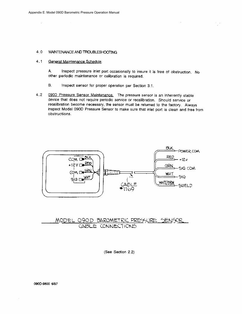
Appendix E Model 090D Barometric Pressure Operation Manual
Appendix E Model 090D Barometric Pressure Operation Manual
Appendix E Model 090D Barometric Pressure Operation Manual
MODEL 375C 8 RAIN GAUGE
OPERATION MANUAL Document No 375-9801
1600 Washington Blvd Regional Sales amp Service Grants Pass Oregon 97526 3206 Main St Suite 106 Telephone 503-471-7111 Rowlett Texas 75088 Facsimile 503-471-7116 Telephone 214-412-4747
Met One Facsimile 214-412-4716
Instruments
Appendix F Model 375C 8rdquo Rain Gauge Operation Manual
MODEL 375C ELECTRIC RAINSNOW SENSOR
OPERATION MANUAL
10 GENERAL INFORtv1ATION
1 1 Model 375C Electric Heated Tipping Bucket RainSnow Gauge is an accurate sensitive and low-maintenance sensor designed to measure rainfall on a continuous basis Water does not collect in the sensor but is drained each time an internal bucket fills with 001 inch of rainfall (standard calibration) At this time a switch closure pulse is also sent to the translator module for counting The sensor is calibrated prior to shipment and requires no adjustments after mounting
1 2 Sensor Cable is a vinyl-jacketed 2-conductor shielded cable connecting to the sensor via an internal terminal strip Cable length is designated in -xx feet on each cable part number label
13 Power Cable is a vinyl-jacketed 3-conductor shielded cable connecting to the sensor heaters with wire nuts in an externally mounted J-8ox Cable length is designated in shyxx feet on each cable part number label
Table 1-1 Model 375C Rainfall Sensor Specifications
Orifice 8 Diameter
Calibration (standard) 0111 Rain per switch closure Calibration (options) 02mm 025mm
Accuracy plusmn1 at 111 to 3 11 per hour at 70deg F
Switch Type Magnet amp Reed
Mounting 3 Pads for 14 bolts on 9-213211 (966) circle diameter
Dimensions 17-34 high 8 diameter not including mounting pads
Power Requirement 110VAC 5060 Hz 315W
Weight less cables 75 Ibs34 kg (10 Ibs shipping wcables)
375C 894 Page 1
Appendix F Model 375C 8rdquo Rain Gauge Operation Manual
20 INSTALLATION
2 1 Choose a site where the height of any nearby trees or other objects above the sensor is no more than about twice their distance from the sensor (Sample 50 ft tree at least 100 away from gauge) A uniform surrounding of objects (such as an orchard) is beneficial as a wind break Nonuniform surroundings (such as a nearby building) creates turbulence which affects accuracy
22 Mount the sensor ~ on a platform using the built in level as an aid The three legs can be adjusted for leveling Three 14 diameter bolts are used to mount the sensor on a 9-2132 (966) bolt circle
23 Remove shipping restraint (This may be tape rubber band or similar item) from sensor bucket and verify that bucket moves freely and that all adjusting screws are tight
24 Connect the signal cable lugs to the terminal strip if not connected already See diagram Polarity is not important See FIGURE 2-1
25 Connect the power cable to the leads inside the condulet (see FIGURE 2-2) if not connected already
26 Replace cover on sensor tightening screws at base
NOTE If snowfall is anticipated remove primary screen from funnel
27 Route signal cable to the translator or datalogger and connect Refer to the System Interconnect Diagram in your system manual for terminal identification
28 Route the power cable to a 11 OVAC power source protected with a 15A GFI circuit Connect (Ref FIGURE 2-2) This wiring must conform to local and state wiring codes If you are not familiar with these codes an electrical contractor should be used
Warning As with any AC power wiring Improper safety procedures can cause fatal injuries If you are not qualified to do this work call an electrical contractor to do It for you
375C 894 Page 2
Appendix F Model 375C 8rdquo Rain Gauge Operation Manual
BABBlER STRIP
ATTACH SIGNAL CABLE LEADS TO SAME
SIGNAL CABLE
TERMINALS AS REED SWITCH (POLARITY NOT IMPORTANT)
fiGURE 2- 375C 894
Page 3
Appendix F Model 375C 8rdquo Rain Gauge Operation Manual
I
CUSTONER i I
-OOKUP shyr
NttRT6HT~ CABLE --J CLMAP
Y
110 VAc 5cI(cO -f PROTECTED BY
gt~CrFl CJ RCl)lTBREb-KER
~E~TER POWER 400KUP fct 2 - 2
375C 894 Page 4
Appendix F Model 375C 8rdquo Rain Gauge Operation Manual
3 0 OPERATIONAL CHECK-OUT
31 Manually actuate tip bucket mechanism (stop-to-stop) three (3) times Confirm that 3 tips have registered on the recording equipment If not refer to Troubleshooting Guide Section 4-3
4 0 MAINTENANCE AND TROUBLESHOOTING
4 1 General Maintenance Schedule At six month intervals perform the following steps
a Clean sensor funnel and buckets b Do NOT lubricate the pivots as any lubricant may attract dust and dirt and cause
wear of the jewel bearings c Verify that buckets move freely and that translator card or datalogger registers
001 or as calibrated for each bucket tip
Based on average to adverse environments
42 Calibration The sensor is factory calibrated recalibration is not required unless damage has occurred or the adjustment screws have loosened To check or recalibrate perform the following steps
a Check to be sure the sensor is level
b Wet the mechanism and tipping bucket assembly Using a graduated cylinder slowly pour the measured quantity of water through the inner funnel to the tipping bucket which should then tip Repeat for the alternate bucket If both buckets tip when filled with the measured quantity of water the sensor is properly calibrated If they do not recalibrate as follows
1 Release the lock nuts on the cup adjustments 2 Move the adjustment screws down to a position that would place the bucket
far out of calibration 3 Allow the measured quantity of water to enter the bucket (Refer to Table
41) 4 Turn the cup adjustment screw up until the bucket assembly tips Tighten
the lock nut 5 Repeat steps 3 and 4 for the opposite bucket 6 Measure the quantity of water necessary to tip each bucket several times to
ensure proper calibration 7 Replace the cover on the gauge
375C 894 Page 5
Appendix F Model 375C 8rdquo Rain Gauge Operation Manual
Table 41 Calibration Quantities
Tip Calibration Water Quantity
001 (standard) 824 milliliters O2mm 649 milliliters O2Smm 811 milliliters
4 3 TROUBLESHCOTING
SYMPTOM
No sensor output
Erroneous Reading
Snow Not Melting
PROBABL~ CAUSE
Faulty Reed Switch
Signal Cable Connection
Lightning Strike
Debris in Funnel
Sensor not level
Sensor out of Calibration
Site too near trees or other objects
Heaters not getting power
Heater Failure
Primary Screen Installed
REMEDY
Replace Reed Switch
Check Connections
Replace Reed Switch amp Diode
Clean (See 41)
Re-level
iecalibrate (see 42)
Relocate (See 21)
Check circuit protector (customer provided)
Return unit to factory for repair
Remove Screen
375C 894 Page 6
Appendix F Model 375C 8rdquo Rain Gauge Operation Manual
375C 894
Appendix F Model 375C 8rdquo Rain Gauge Operation Manual
RENOYE iP CSNOW S
A~lCl PATED
TO CO~NECTOR
ON BASE ACOSY
~OUSlt1GFUNNEL ASSEMBLY 375C 894 FIGURE 4-3
Appendix F Model 375C 8rdquo Rain Gauge Operation Manual
375C 894 Page 9
Appendix F Model 375C 8rdquo Rain Gauge Operation Manual
44 REPLACEABLE PARTS LIST
Mode 375C Rain Gauge Parts List
10 No Part No
1 2545 2 2492 3 340070 4 480210 5 2598 6 2503 7 480510 8 2934 9 2936 1 0 2937 1 1 1566 1 1 2745 1 2 2504 1 3 2666 4 2516
45 REPAIR AND RECALBRATION SERVICE
Description
Assembly Tip Bucket (01 2mm 25mm) Pin Pivot Barrier Strip - 3 pos Nut Crown Nylon 8-32 Screen Screen Primary Top Clamp Liquid-Tight Reed Switch Cartridge Adjustable Magnet Bracket Lightning Protection Diode Standard Cable Assembly Cable Assembly (for use with Automet) Screen Secondary Assembly HousingFunnel 8 (115VAC) Foot
This service provided by Met One Instruments enables fast economical service for the user This repair and calibration service includes disassembly inspection cleaning reassembly and calibration Components will be replaced as required Additional charges for additional materials only will be added to the basic service charge
375C 894 Page 10
Appendix F Model 375C 8rdquo Rain Gauge Operation Manual
SIIru1
COInWIl
Sil I ElD
SENSOR END TRANSLATOR nw ~ ---- fi f____ -poundltshy~-- G-pound shy
r-= f(--JL 1
I ~--cJ t5(t)
IDENTIFY CABtE lB ROll EACII END D~SIl NUlIllER LENGTi I N FEET
TEll PART NO liE I~ 111 ION QTY
2
LUG SPAUB Rd 5
CABIE 2 IIHE SllIEIDlm -
600193
4[)OIlIO
960050 -~------ ------------------------j
SlnVING 14 SHRINK
7 IllIE 22 AWl iliTurm -------------------------lr--~
8 SLEEV INC 14 CLEAI~ SHRINK
10
MET ONE 1
ASSY CAnLE~ RAIN
Appendix F Model 375C 8rdquo Rain Gauge Operation Manual
SIfNAL
2 I COMMON
3
4
--e-
SENSOR FNO DATALOrCER rND
--=1--- 6
IDENTIFY CAHtE 1(1 FROIl EACH ENDamp DASH HYDER = LENGTH IN FEFT STANDARD lENGTIl = 50 FT
amp STRIP AND TIN WIRE ENDS Imiddot
SOLllEflt CUP VIEW
llFSCltl [ION
-1 PIN FEllAtE
bull 14 SHRINK
4 CLEAR SIIRf HK
MET ONE INSTRUMENTS
ASSY~ CADLE RAIN GAUGE
Appendix F Model 375C 8rdquo Rain Gauge Operation Manual
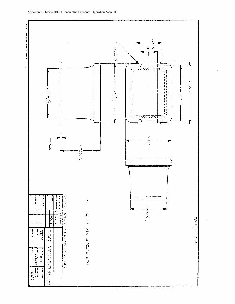
Appendix E Model 090D Barometric Pressure Operation Manual
Appendix E Model 090D Barometric Pressure Operation Manual
MODEL 375C 8 RAIN GAUGE
OPERATION MANUAL Document No 375-9801
1600 Washington Blvd Regional Sales amp Service Grants Pass Oregon 97526 3206 Main St Suite 106 Telephone 503-471-7111 Rowlett Texas 75088 Facsimile 503-471-7116 Telephone 214-412-4747
Met One Facsimile 214-412-4716
Instruments
Appendix F Model 375C 8rdquo Rain Gauge Operation Manual
MODEL 375C ELECTRIC RAINSNOW SENSOR
OPERATION MANUAL
10 GENERAL INFORtv1ATION
1 1 Model 375C Electric Heated Tipping Bucket RainSnow Gauge is an accurate sensitive and low-maintenance sensor designed to measure rainfall on a continuous basis Water does not collect in the sensor but is drained each time an internal bucket fills with 001 inch of rainfall (standard calibration) At this time a switch closure pulse is also sent to the translator module for counting The sensor is calibrated prior to shipment and requires no adjustments after mounting
1 2 Sensor Cable is a vinyl-jacketed 2-conductor shielded cable connecting to the sensor via an internal terminal strip Cable length is designated in -xx feet on each cable part number label
13 Power Cable is a vinyl-jacketed 3-conductor shielded cable connecting to the sensor heaters with wire nuts in an externally mounted J-8ox Cable length is designated in shyxx feet on each cable part number label
Table 1-1 Model 375C Rainfall Sensor Specifications
Orifice 8 Diameter
Calibration (standard) 0111 Rain per switch closure Calibration (options) 02mm 025mm
Accuracy plusmn1 at 111 to 3 11 per hour at 70deg F
Switch Type Magnet amp Reed
Mounting 3 Pads for 14 bolts on 9-213211 (966) circle diameter
Dimensions 17-34 high 8 diameter not including mounting pads
Power Requirement 110VAC 5060 Hz 315W
Weight less cables 75 Ibs34 kg (10 Ibs shipping wcables)
375C 894 Page 1
Appendix F Model 375C 8rdquo Rain Gauge Operation Manual
20 INSTALLATION
2 1 Choose a site where the height of any nearby trees or other objects above the sensor is no more than about twice their distance from the sensor (Sample 50 ft tree at least 100 away from gauge) A uniform surrounding of objects (such as an orchard) is beneficial as a wind break Nonuniform surroundings (such as a nearby building) creates turbulence which affects accuracy
22 Mount the sensor ~ on a platform using the built in level as an aid The three legs can be adjusted for leveling Three 14 diameter bolts are used to mount the sensor on a 9-2132 (966) bolt circle
23 Remove shipping restraint (This may be tape rubber band or similar item) from sensor bucket and verify that bucket moves freely and that all adjusting screws are tight
24 Connect the signal cable lugs to the terminal strip if not connected already See diagram Polarity is not important See FIGURE 2-1
25 Connect the power cable to the leads inside the condulet (see FIGURE 2-2) if not connected already
26 Replace cover on sensor tightening screws at base
NOTE If snowfall is anticipated remove primary screen from funnel
27 Route signal cable to the translator or datalogger and connect Refer to the System Interconnect Diagram in your system manual for terminal identification
28 Route the power cable to a 11 OVAC power source protected with a 15A GFI circuit Connect (Ref FIGURE 2-2) This wiring must conform to local and state wiring codes If you are not familiar with these codes an electrical contractor should be used
Warning As with any AC power wiring Improper safety procedures can cause fatal injuries If you are not qualified to do this work call an electrical contractor to do It for you
375C 894 Page 2
Appendix F Model 375C 8rdquo Rain Gauge Operation Manual
BABBlER STRIP
ATTACH SIGNAL CABLE LEADS TO SAME
SIGNAL CABLE
TERMINALS AS REED SWITCH (POLARITY NOT IMPORTANT)
fiGURE 2- 375C 894
Page 3
Appendix F Model 375C 8rdquo Rain Gauge Operation Manual
I
CUSTONER i I
-OOKUP shyr
NttRT6HT~ CABLE --J CLMAP
Y
110 VAc 5cI(cO -f PROTECTED BY
gt~CrFl CJ RCl)lTBREb-KER
~E~TER POWER 400KUP fct 2 - 2
375C 894 Page 4
Appendix F Model 375C 8rdquo Rain Gauge Operation Manual
3 0 OPERATIONAL CHECK-OUT
31 Manually actuate tip bucket mechanism (stop-to-stop) three (3) times Confirm that 3 tips have registered on the recording equipment If not refer to Troubleshooting Guide Section 4-3
4 0 MAINTENANCE AND TROUBLESHOOTING
4 1 General Maintenance Schedule At six month intervals perform the following steps
a Clean sensor funnel and buckets b Do NOT lubricate the pivots as any lubricant may attract dust and dirt and cause
wear of the jewel bearings c Verify that buckets move freely and that translator card or datalogger registers
001 or as calibrated for each bucket tip
Based on average to adverse environments
42 Calibration The sensor is factory calibrated recalibration is not required unless damage has occurred or the adjustment screws have loosened To check or recalibrate perform the following steps
a Check to be sure the sensor is level
b Wet the mechanism and tipping bucket assembly Using a graduated cylinder slowly pour the measured quantity of water through the inner funnel to the tipping bucket which should then tip Repeat for the alternate bucket If both buckets tip when filled with the measured quantity of water the sensor is properly calibrated If they do not recalibrate as follows
1 Release the lock nuts on the cup adjustments 2 Move the adjustment screws down to a position that would place the bucket
far out of calibration 3 Allow the measured quantity of water to enter the bucket (Refer to Table
41) 4 Turn the cup adjustment screw up until the bucket assembly tips Tighten
the lock nut 5 Repeat steps 3 and 4 for the opposite bucket 6 Measure the quantity of water necessary to tip each bucket several times to
ensure proper calibration 7 Replace the cover on the gauge
375C 894 Page 5
Appendix F Model 375C 8rdquo Rain Gauge Operation Manual
Table 41 Calibration Quantities
Tip Calibration Water Quantity
001 (standard) 824 milliliters O2mm 649 milliliters O2Smm 811 milliliters
4 3 TROUBLESHCOTING
SYMPTOM
No sensor output
Erroneous Reading
Snow Not Melting
PROBABL~ CAUSE
Faulty Reed Switch
Signal Cable Connection
Lightning Strike
Debris in Funnel
Sensor not level
Sensor out of Calibration
Site too near trees or other objects
Heaters not getting power
Heater Failure
Primary Screen Installed
REMEDY
Replace Reed Switch
Check Connections
Replace Reed Switch amp Diode
Clean (See 41)
Re-level
iecalibrate (see 42)
Relocate (See 21)
Check circuit protector (customer provided)
Return unit to factory for repair
Remove Screen
375C 894 Page 6
Appendix F Model 375C 8rdquo Rain Gauge Operation Manual
375C 894
Appendix F Model 375C 8rdquo Rain Gauge Operation Manual
RENOYE iP CSNOW S
A~lCl PATED
TO CO~NECTOR
ON BASE ACOSY
~OUSlt1GFUNNEL ASSEMBLY 375C 894 FIGURE 4-3
Appendix F Model 375C 8rdquo Rain Gauge Operation Manual
375C 894 Page 9
Appendix F Model 375C 8rdquo Rain Gauge Operation Manual
44 REPLACEABLE PARTS LIST
Mode 375C Rain Gauge Parts List
10 No Part No
1 2545 2 2492 3 340070 4 480210 5 2598 6 2503 7 480510 8 2934 9 2936 1 0 2937 1 1 1566 1 1 2745 1 2 2504 1 3 2666 4 2516
45 REPAIR AND RECALBRATION SERVICE
Description
Assembly Tip Bucket (01 2mm 25mm) Pin Pivot Barrier Strip - 3 pos Nut Crown Nylon 8-32 Screen Screen Primary Top Clamp Liquid-Tight Reed Switch Cartridge Adjustable Magnet Bracket Lightning Protection Diode Standard Cable Assembly Cable Assembly (for use with Automet) Screen Secondary Assembly HousingFunnel 8 (115VAC) Foot
This service provided by Met One Instruments enables fast economical service for the user This repair and calibration service includes disassembly inspection cleaning reassembly and calibration Components will be replaced as required Additional charges for additional materials only will be added to the basic service charge
375C 894 Page 10
Appendix F Model 375C 8rdquo Rain Gauge Operation Manual
SIIru1
COInWIl
Sil I ElD
SENSOR END TRANSLATOR nw ~ ---- fi f____ -poundltshy~-- G-pound shy
r-= f(--JL 1
I ~--cJ t5(t)
IDENTIFY CABtE lB ROll EACII END D~SIl NUlIllER LENGTi I N FEET
TEll PART NO liE I~ 111 ION QTY
2
LUG SPAUB Rd 5
CABIE 2 IIHE SllIEIDlm -
600193
4[)OIlIO
960050 -~------ ------------------------j
SlnVING 14 SHRINK
7 IllIE 22 AWl iliTurm -------------------------lr--~
8 SLEEV INC 14 CLEAI~ SHRINK
10
MET ONE 1
ASSY CAnLE~ RAIN
Appendix F Model 375C 8rdquo Rain Gauge Operation Manual
SIfNAL
2 I COMMON
3
4
--e-
SENSOR FNO DATALOrCER rND
--=1--- 6
IDENTIFY CAHtE 1(1 FROIl EACH ENDamp DASH HYDER = LENGTH IN FEFT STANDARD lENGTIl = 50 FT
amp STRIP AND TIN WIRE ENDS Imiddot
SOLllEflt CUP VIEW
llFSCltl [ION
-1 PIN FEllAtE
bull 14 SHRINK
4 CLEAR SIIRf HK
MET ONE INSTRUMENTS
ASSY~ CADLE RAIN GAUGE
Appendix F Model 375C 8rdquo Rain Gauge Operation Manual
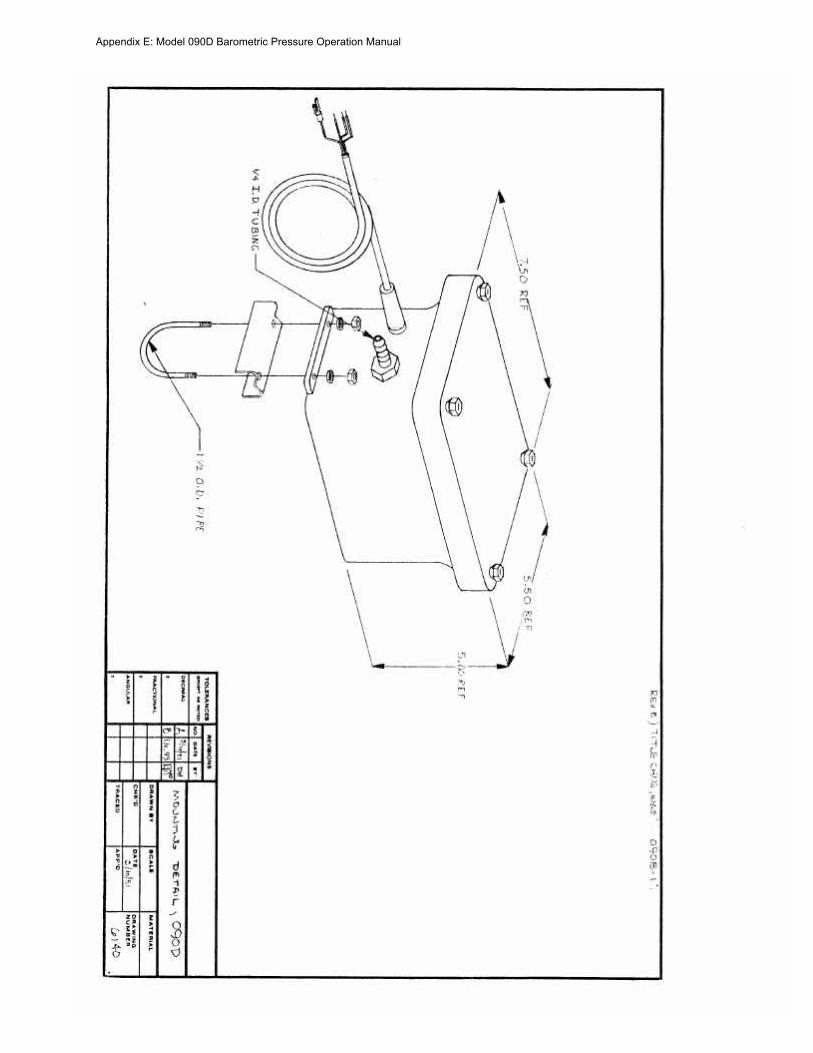
Appendix E Model 090D Barometric Pressure Operation Manual
MODEL 375C 8 RAIN GAUGE
OPERATION MANUAL Document No 375-9801
1600 Washington Blvd Regional Sales amp Service Grants Pass Oregon 97526 3206 Main St Suite 106 Telephone 503-471-7111 Rowlett Texas 75088 Facsimile 503-471-7116 Telephone 214-412-4747
Met One Facsimile 214-412-4716
Instruments
Appendix F Model 375C 8rdquo Rain Gauge Operation Manual
MODEL 375C ELECTRIC RAINSNOW SENSOR
OPERATION MANUAL
10 GENERAL INFORtv1ATION
1 1 Model 375C Electric Heated Tipping Bucket RainSnow Gauge is an accurate sensitive and low-maintenance sensor designed to measure rainfall on a continuous basis Water does not collect in the sensor but is drained each time an internal bucket fills with 001 inch of rainfall (standard calibration) At this time a switch closure pulse is also sent to the translator module for counting The sensor is calibrated prior to shipment and requires no adjustments after mounting
1 2 Sensor Cable is a vinyl-jacketed 2-conductor shielded cable connecting to the sensor via an internal terminal strip Cable length is designated in -xx feet on each cable part number label
13 Power Cable is a vinyl-jacketed 3-conductor shielded cable connecting to the sensor heaters with wire nuts in an externally mounted J-8ox Cable length is designated in shyxx feet on each cable part number label
Table 1-1 Model 375C Rainfall Sensor Specifications
Orifice 8 Diameter
Calibration (standard) 0111 Rain per switch closure Calibration (options) 02mm 025mm
Accuracy plusmn1 at 111 to 3 11 per hour at 70deg F
Switch Type Magnet amp Reed
Mounting 3 Pads for 14 bolts on 9-213211 (966) circle diameter
Dimensions 17-34 high 8 diameter not including mounting pads
Power Requirement 110VAC 5060 Hz 315W
Weight less cables 75 Ibs34 kg (10 Ibs shipping wcables)
375C 894 Page 1
Appendix F Model 375C 8rdquo Rain Gauge Operation Manual
20 INSTALLATION
2 1 Choose a site where the height of any nearby trees or other objects above the sensor is no more than about twice their distance from the sensor (Sample 50 ft tree at least 100 away from gauge) A uniform surrounding of objects (such as an orchard) is beneficial as a wind break Nonuniform surroundings (such as a nearby building) creates turbulence which affects accuracy
22 Mount the sensor ~ on a platform using the built in level as an aid The three legs can be adjusted for leveling Three 14 diameter bolts are used to mount the sensor on a 9-2132 (966) bolt circle
23 Remove shipping restraint (This may be tape rubber band or similar item) from sensor bucket and verify that bucket moves freely and that all adjusting screws are tight
24 Connect the signal cable lugs to the terminal strip if not connected already See diagram Polarity is not important See FIGURE 2-1
25 Connect the power cable to the leads inside the condulet (see FIGURE 2-2) if not connected already
26 Replace cover on sensor tightening screws at base
NOTE If snowfall is anticipated remove primary screen from funnel
27 Route signal cable to the translator or datalogger and connect Refer to the System Interconnect Diagram in your system manual for terminal identification
28 Route the power cable to a 11 OVAC power source protected with a 15A GFI circuit Connect (Ref FIGURE 2-2) This wiring must conform to local and state wiring codes If you are not familiar with these codes an electrical contractor should be used
Warning As with any AC power wiring Improper safety procedures can cause fatal injuries If you are not qualified to do this work call an electrical contractor to do It for you
375C 894 Page 2
Appendix F Model 375C 8rdquo Rain Gauge Operation Manual
BABBlER STRIP
ATTACH SIGNAL CABLE LEADS TO SAME
SIGNAL CABLE
TERMINALS AS REED SWITCH (POLARITY NOT IMPORTANT)
fiGURE 2- 375C 894
Page 3
Appendix F Model 375C 8rdquo Rain Gauge Operation Manual
I
CUSTONER i I
-OOKUP shyr
NttRT6HT~ CABLE --J CLMAP
Y
110 VAc 5cI(cO -f PROTECTED BY
gt~CrFl CJ RCl)lTBREb-KER
~E~TER POWER 400KUP fct 2 - 2
375C 894 Page 4
Appendix F Model 375C 8rdquo Rain Gauge Operation Manual
3 0 OPERATIONAL CHECK-OUT
31 Manually actuate tip bucket mechanism (stop-to-stop) three (3) times Confirm that 3 tips have registered on the recording equipment If not refer to Troubleshooting Guide Section 4-3
4 0 MAINTENANCE AND TROUBLESHOOTING
4 1 General Maintenance Schedule At six month intervals perform the following steps
a Clean sensor funnel and buckets b Do NOT lubricate the pivots as any lubricant may attract dust and dirt and cause
wear of the jewel bearings c Verify that buckets move freely and that translator card or datalogger registers
001 or as calibrated for each bucket tip
Based on average to adverse environments
42 Calibration The sensor is factory calibrated recalibration is not required unless damage has occurred or the adjustment screws have loosened To check or recalibrate perform the following steps
a Check to be sure the sensor is level
b Wet the mechanism and tipping bucket assembly Using a graduated cylinder slowly pour the measured quantity of water through the inner funnel to the tipping bucket which should then tip Repeat for the alternate bucket If both buckets tip when filled with the measured quantity of water the sensor is properly calibrated If they do not recalibrate as follows
1 Release the lock nuts on the cup adjustments 2 Move the adjustment screws down to a position that would place the bucket
far out of calibration 3 Allow the measured quantity of water to enter the bucket (Refer to Table
41) 4 Turn the cup adjustment screw up until the bucket assembly tips Tighten
the lock nut 5 Repeat steps 3 and 4 for the opposite bucket 6 Measure the quantity of water necessary to tip each bucket several times to
ensure proper calibration 7 Replace the cover on the gauge
375C 894 Page 5
Appendix F Model 375C 8rdquo Rain Gauge Operation Manual
Table 41 Calibration Quantities
Tip Calibration Water Quantity
001 (standard) 824 milliliters O2mm 649 milliliters O2Smm 811 milliliters
4 3 TROUBLESHCOTING
SYMPTOM
No sensor output
Erroneous Reading
Snow Not Melting
PROBABL~ CAUSE
Faulty Reed Switch
Signal Cable Connection
Lightning Strike
Debris in Funnel
Sensor not level
Sensor out of Calibration
Site too near trees or other objects
Heaters not getting power
Heater Failure
Primary Screen Installed
REMEDY
Replace Reed Switch
Check Connections
Replace Reed Switch amp Diode
Clean (See 41)
Re-level
iecalibrate (see 42)
Relocate (See 21)
Check circuit protector (customer provided)
Return unit to factory for repair
Remove Screen
375C 894 Page 6
Appendix F Model 375C 8rdquo Rain Gauge Operation Manual
375C 894
Appendix F Model 375C 8rdquo Rain Gauge Operation Manual
RENOYE iP CSNOW S
A~lCl PATED
TO CO~NECTOR
ON BASE ACOSY
~OUSlt1GFUNNEL ASSEMBLY 375C 894 FIGURE 4-3
Appendix F Model 375C 8rdquo Rain Gauge Operation Manual
375C 894 Page 9
Appendix F Model 375C 8rdquo Rain Gauge Operation Manual
44 REPLACEABLE PARTS LIST
Mode 375C Rain Gauge Parts List
10 No Part No
1 2545 2 2492 3 340070 4 480210 5 2598 6 2503 7 480510 8 2934 9 2936 1 0 2937 1 1 1566 1 1 2745 1 2 2504 1 3 2666 4 2516
45 REPAIR AND RECALBRATION SERVICE
Description
Assembly Tip Bucket (01 2mm 25mm) Pin Pivot Barrier Strip - 3 pos Nut Crown Nylon 8-32 Screen Screen Primary Top Clamp Liquid-Tight Reed Switch Cartridge Adjustable Magnet Bracket Lightning Protection Diode Standard Cable Assembly Cable Assembly (for use with Automet) Screen Secondary Assembly HousingFunnel 8 (115VAC) Foot
This service provided by Met One Instruments enables fast economical service for the user This repair and calibration service includes disassembly inspection cleaning reassembly and calibration Components will be replaced as required Additional charges for additional materials only will be added to the basic service charge
375C 894 Page 10
Appendix F Model 375C 8rdquo Rain Gauge Operation Manual
SIIru1
COInWIl
Sil I ElD
SENSOR END TRANSLATOR nw ~ ---- fi f____ -poundltshy~-- G-pound shy
r-= f(--JL 1
I ~--cJ t5(t)
IDENTIFY CABtE lB ROll EACII END D~SIl NUlIllER LENGTi I N FEET
TEll PART NO liE I~ 111 ION QTY
2
LUG SPAUB Rd 5
CABIE 2 IIHE SllIEIDlm -
600193
4[)OIlIO
960050 -~------ ------------------------j
SlnVING 14 SHRINK
7 IllIE 22 AWl iliTurm -------------------------lr--~
8 SLEEV INC 14 CLEAI~ SHRINK
10
MET ONE 1
ASSY CAnLE~ RAIN
Appendix F Model 375C 8rdquo Rain Gauge Operation Manual
SIfNAL
2 I COMMON
3
4
--e-
SENSOR FNO DATALOrCER rND
--=1--- 6
IDENTIFY CAHtE 1(1 FROIl EACH ENDamp DASH HYDER = LENGTH IN FEFT STANDARD lENGTIl = 50 FT
amp STRIP AND TIN WIRE ENDS Imiddot
SOLllEflt CUP VIEW
llFSCltl [ION
-1 PIN FEllAtE
bull 14 SHRINK
4 CLEAR SIIRf HK
MET ONE INSTRUMENTS
ASSY~ CADLE RAIN GAUGE
Appendix F Model 375C 8rdquo Rain Gauge Operation Manual
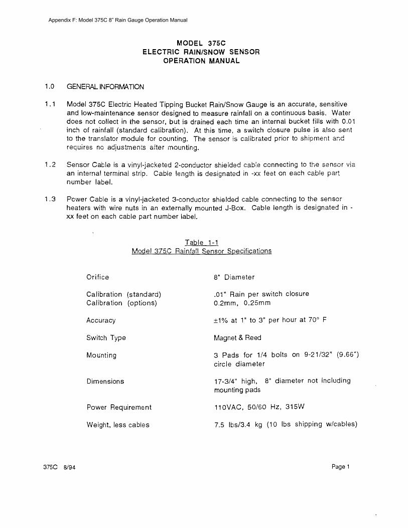
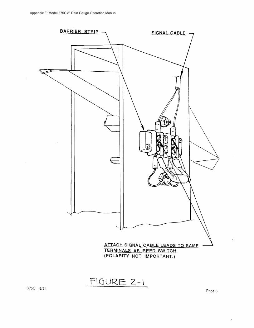
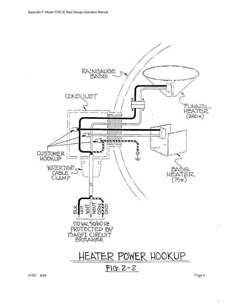
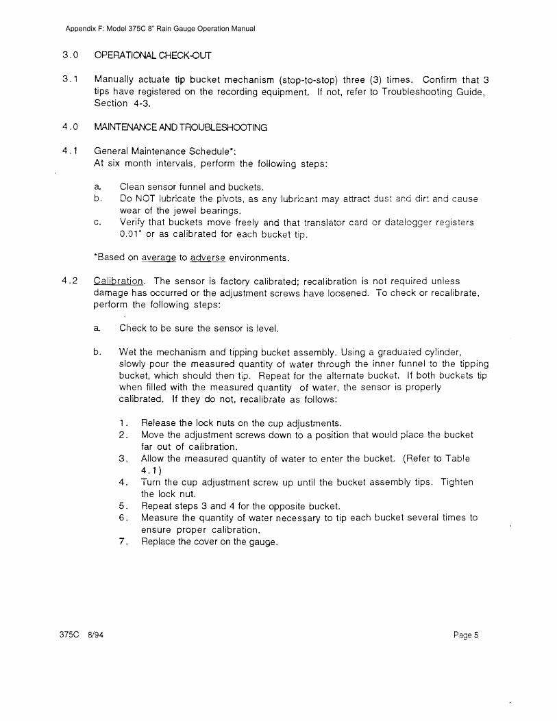
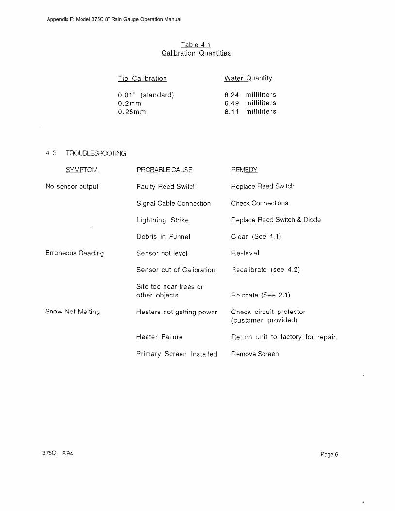
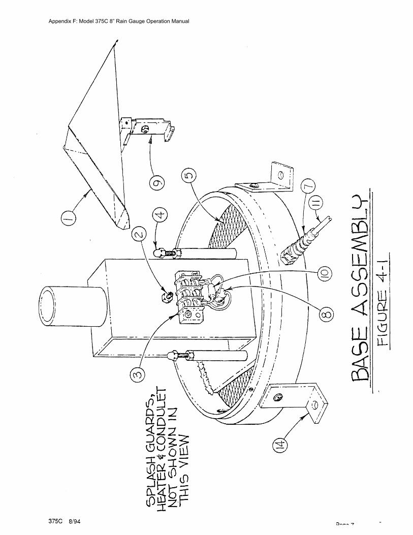
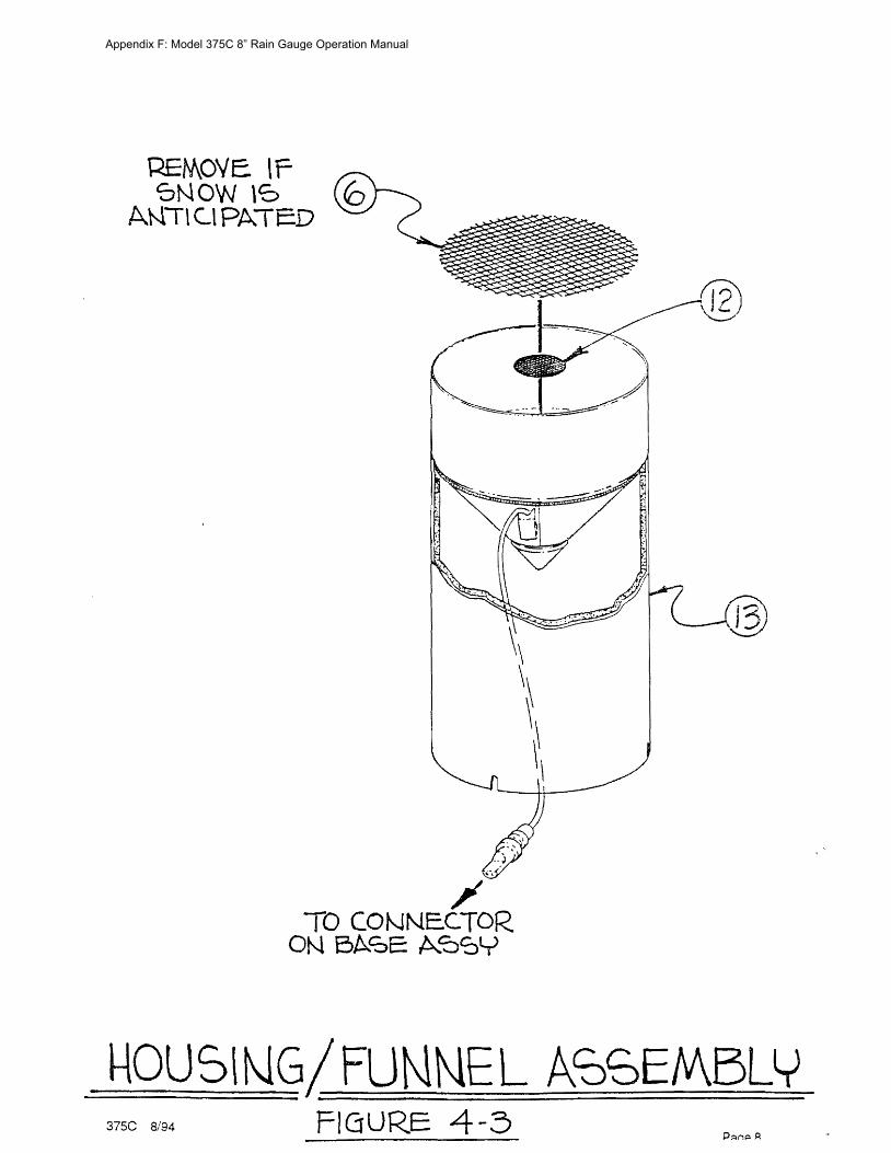
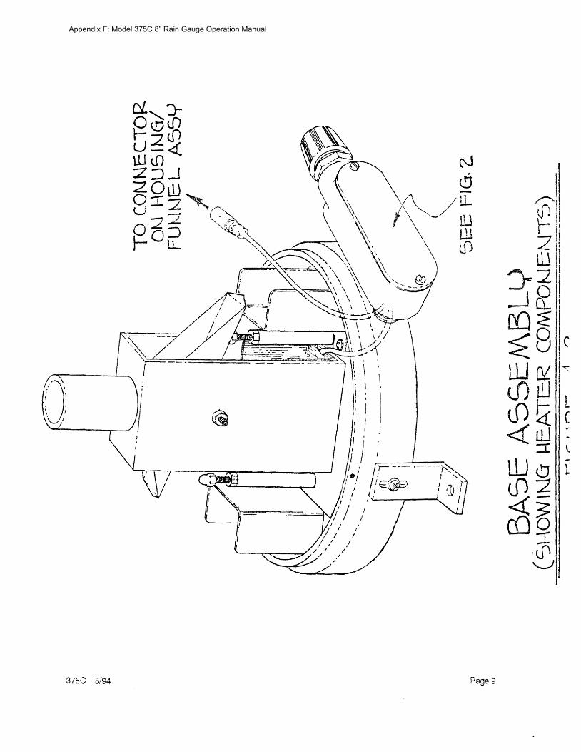
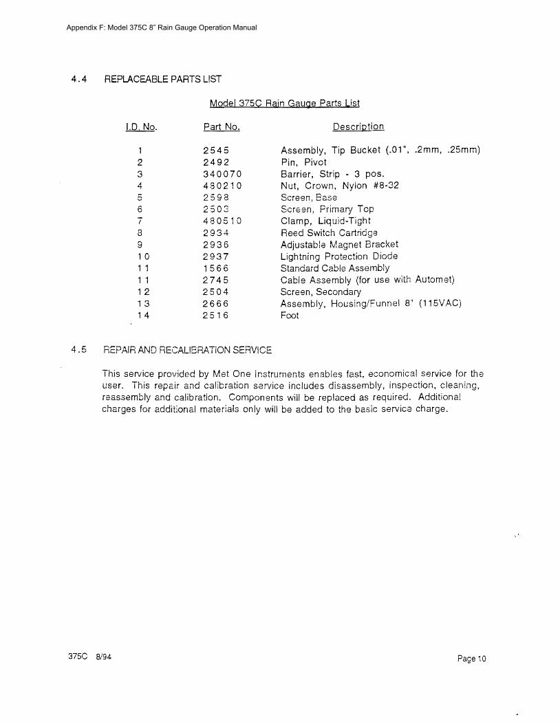
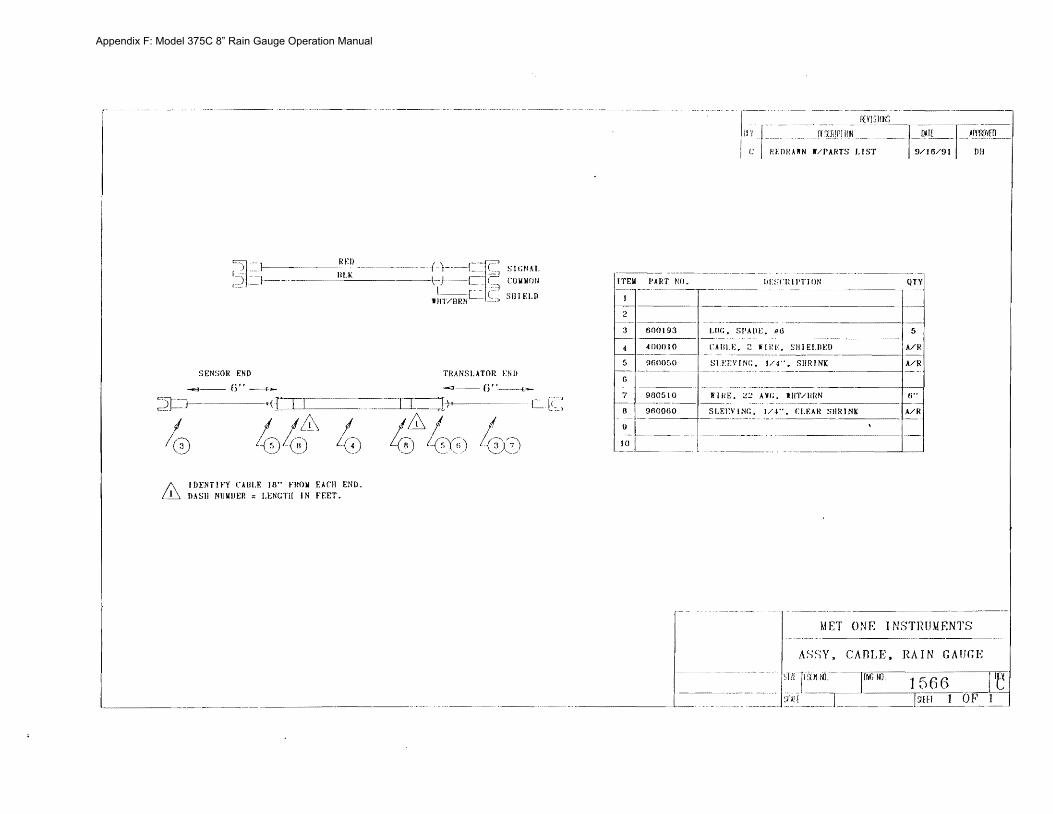
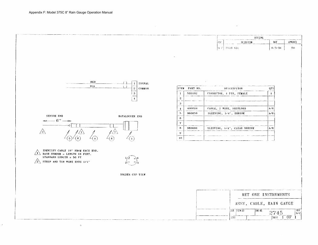
Recommended