slide 1 9/8/09
Aerospace and Ocean Engineering
Classical Aircraft Sizing I W. H. Mason
from Sandusky, Northrop
slide 2 9/8/09
Aerospace and Ocean Engineering
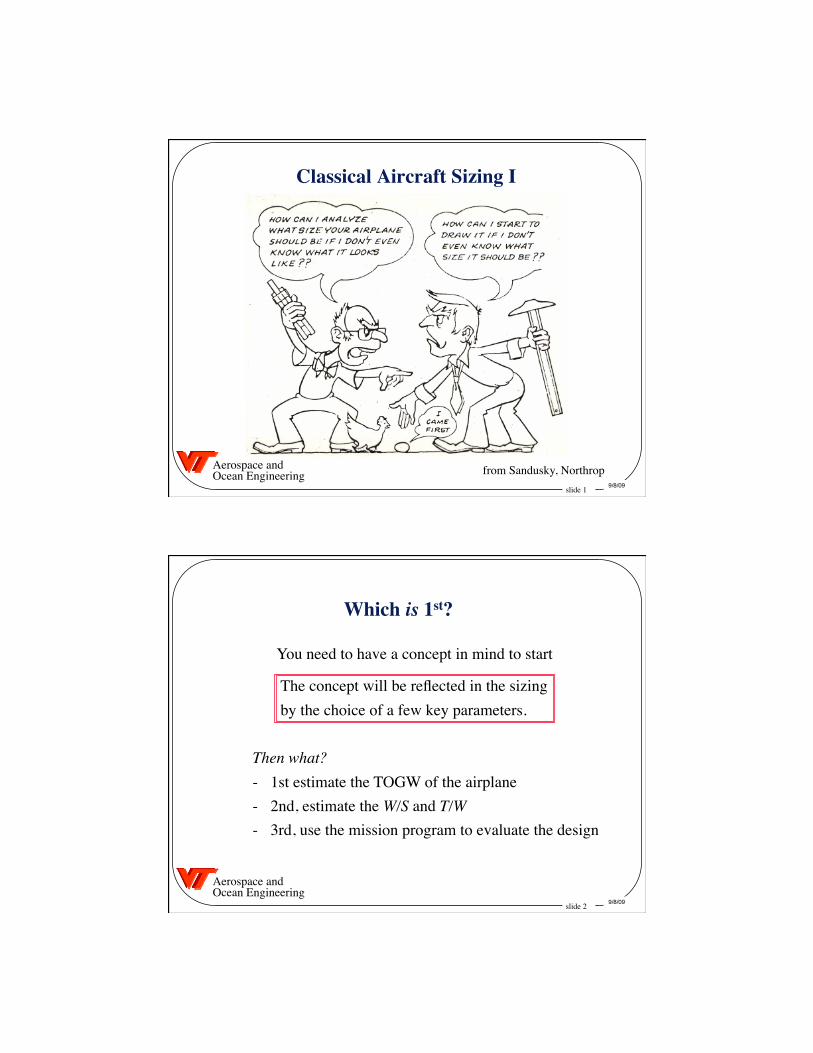
Which is 1st?
You need to have a concept in mind to start
The concept will be reflected in the sizing by the choice of a few key parameters.
Then what? - 1st estimate the TOGW of the airplane - 2nd, estimate the W/S and T/W - 3rd, use the mission program to evaluate the design
slide 3 9/8/09
Aerospace and Ocean Engineering
To Start: Define a Mission What is this airplane supposed to do? • How far does it go? How fast? • What and how much does it carry? • What are the landing and takeoff requirements? • Are there any maneuver/accel requirements? (these are known as point performance req’ts)
• What MIL or FAR req’ts must be satisfied? Taken together, the answers to these questions are
known as the Mission Statement, and also imply that you think of concepts to do the job
Note: the web slides contain more charts. Fill in details
slide 4 9/8/09
Aerospace and Ocean Engineering
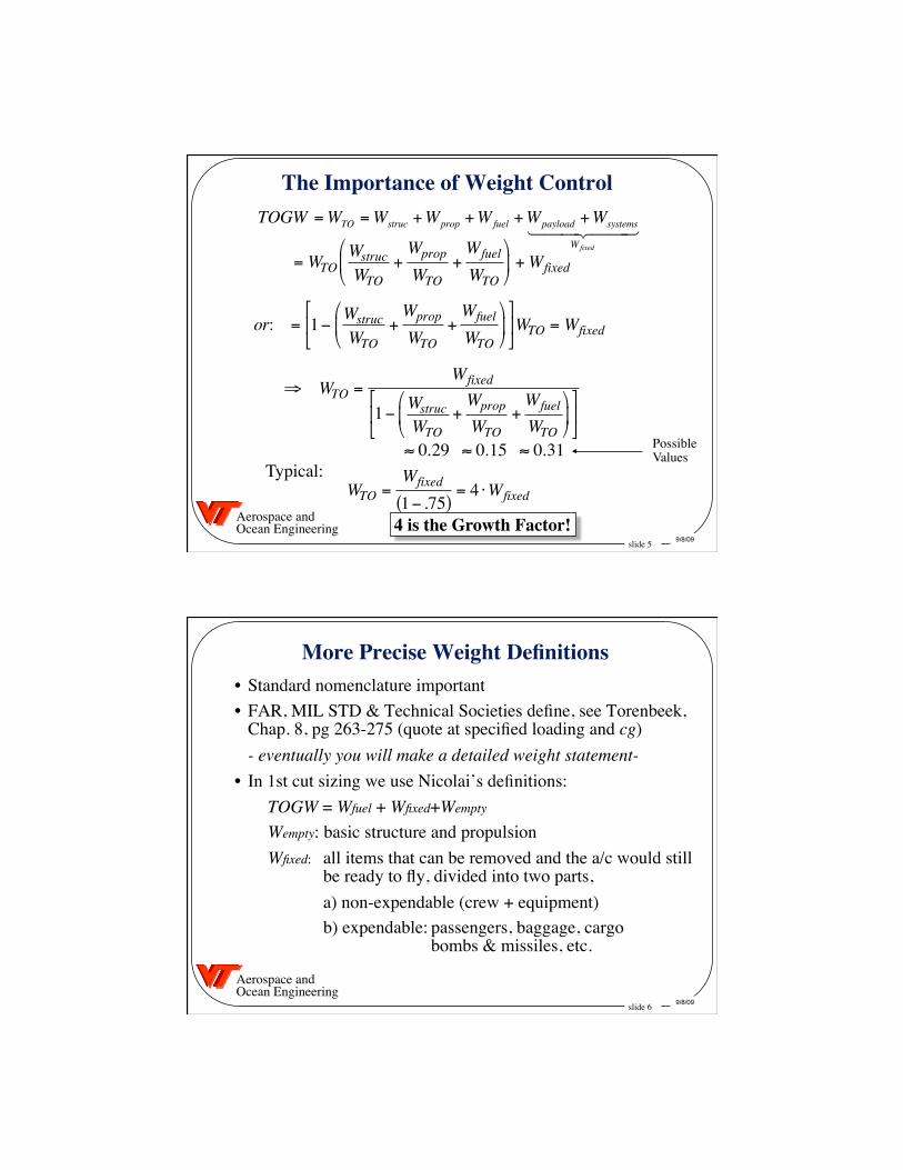
Basis for Sizing • Many Possibilities for the Selection Criteria • Possible Choices: - minimum life cycle cost - " flyaway cost - " direct operating cost - " fuel cost - " take off gross weight (TOGW) • Cost is the real selection criteria, but hard to estimate • For a given class of aircraft, aircraft cost/lb is similar ∴ min weight is a good choice for comparing alternatives
slide 5 9/8/09
Aerospace and Ocean Engineering
The Importance of Weight Control
4 is the Growth Factor!
Typical: Possible Values
WTO =Wfixed
1− .75( )= 4 ⋅Wfixed
or: = 1− WstrucWTO
+Wprop
WTO+Wfuel
WTO
WTO = Wfixed
⇒ WTO =Wfixed
1− WstrucWTO
+Wprop
WTO+Wfuel
WTO
TOGW =WTO =Wstruc +Wprop +Wfuel +Wpayload +Wsystems
Wfixed
= WTOWstrucWTO
+Wprop
WTO+Wfuel
WTO
+Wfixed
≈ 0.29 ≈ 0.15 ≈ 0.31
slide 6 9/8/09
Aerospace and Ocean Engineering
More Precise Weight Definitions • Standard nomenclature important • FAR, MIL STD & Technical Societies define, see Torenbeek,
Chap. 8, pg 263-275 (quote at specified loading and cg) - eventually you will make a detailed weight statement- • In 1st cut sizing we use Nicolai’s definitions: TOGW = Wfuel + Wfixed+Wempty
Wempty: basic structure and propulsion Wfixed: all items that can be removed and the a/c would still be ready to fly, divided into two parts,
a) non-expendable (crew + equipment) b) expendable: passengers, baggage, cargo bombs & missiles, etc.
slide 7 9/8/09
Aerospace and Ocean Engineering
1st Cut Sizing
We will use Nicolai’s Method in Class Examples
Several Methods Available: • Nicolai, Chap. 5 • Roskam, Vol. 1 (both Jets and Props) • Raymer, Chap. 6 and 19 (Chap. 3 too crude, but read) • Loftin, Chap. 3 and 4 (Jet) and Chap. 6 and 7 (Prop) (available on class web page - >400M) • Torenbeek, pp. 144-148, 171-180
Note: books on reserve in the Architecture Library: see Schetz on the Library reserve page
slide 8 9/8/09
Aerospace and Ocean Engineering
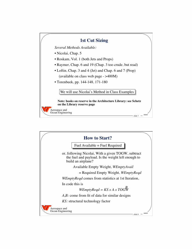
Fuel Available = Fuel Required
How to Start?
or, following Nicolai, With a given TOGW, subtract the fuel and payload. Is the weight left enough to build an airplane?
Available Empty Weight, WEmptyAvail = Required Empty Weight, WEmptyReqd WEmptyReqd comes from statistics at 1st Iteration, In code this is WEmptyReqd = KS x A x TOGW A,B: come from fit of data for similar designs KS: structural technology factor
B
slide 9 9/8/09
Aerospace and Ocean Engineering
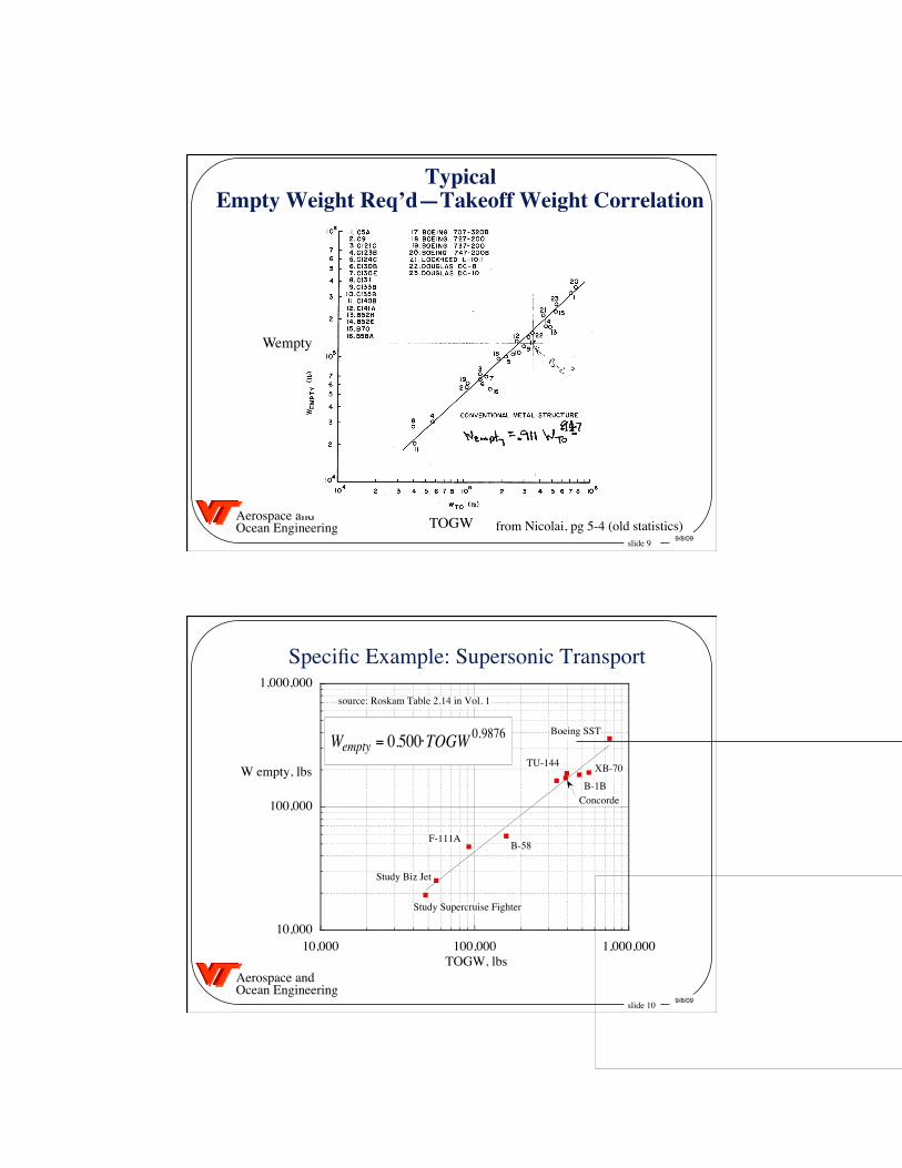
Typical�Empty Weight Req’d—Takeoff Weight Correlation
from Nicolai, pg 5-4 (old statistics) TOGW
Wempty
slide 10 9/8/09
Aerospace and Ocean Engineering
Specific Example: Supersonic Transport
10,000
100,000
1,000,000
10,000 100,000 1,000,000
W empty, lbs
TOGW, lbs
source: Roskam Table 2.14 in Vol. 1
€
Wempty = 0.500⋅TOGW 0.9876
F-111AB-58
Study Biz Jet
Study Supercruise Fighter
Boeing SST
ConcordeB-1B
TU-144 XB-70
slide 11 9/8/09
Aerospace and Ocean Engineering
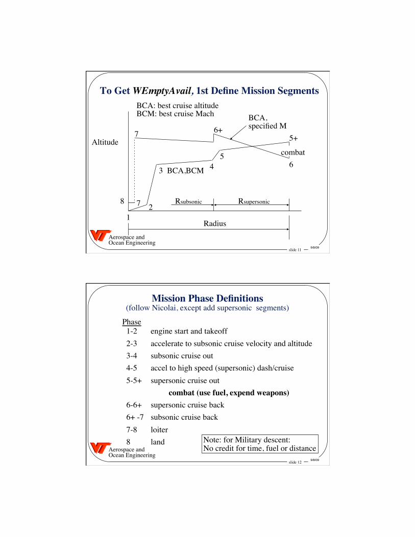
To Get WEmptyAvail, 1st Define Mission Segments
Radius
Altitude
1 2
3 4 5
5+
6
6+ 7
7 8 Rsupersonic Rsubsonic
BCA,BCM
BCA, specified M
BCA: best cruise altitude BCM: best cruise Mach
combat
slide 12 9/8/09
Aerospace and Ocean Engineering
Mission Phase Definitions �(follow Nicolai, except add supersonic segments)
1-2 engine start and takeoff 2-3 accelerate to subsonic cruise velocity and altitude 3-4 subsonic cruise out 4-5 accel to high speed (supersonic) dash/cruise 5-5+ supersonic cruise out combat (use fuel, expend weapons) 6-6+ supersonic cruise back 6+ -7 subsonic cruise back 7-8 loiter 8 land
Phase
Note: for Military descent: No credit for time, fuel or distance
slide 13 9/8/09
Aerospace and Ocean Engineering
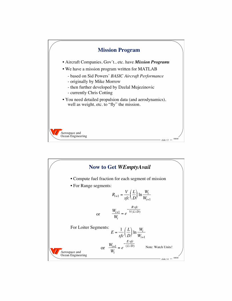
Mission Program
• Aircraft Companies, Gov’t., etc. have Mission Programs • We have a mission program written for MATLAB - based on Sid Powers’ BASIC Aircraft Performance - originally by Mike Morrow - then further developed by Dzelal Mujezinovic - currently Chris Cotting • You need detailed propulsion data (and aerodynamics),
well as weight, etc. to “fly” the mission.
slide 14 9/8/09
Aerospace and Ocean Engineering
Now to Get WEmptyAvail
• Compute fuel fraction for each segment of mission • For Range segments:
For Loiter Segments:
Note: Watch Units!
or
or
Ri+1 =Vsfc
LD
ln Wi
Wi+1
E =1sfc
LD
ln Wi
Wi+1
Wi+1Wi
= e−
R⋅sfcV (L/D)
Wi+1Wi
= e−E⋅sfc(L/D)
slide 15 9/8/09
Aerospace and Ocean Engineering
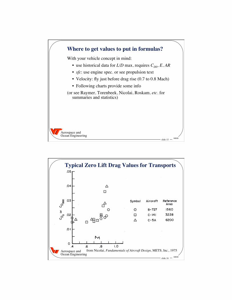
Where to get values to put in formulas? With your vehicle concept in mind: • use historical data for L/D max, requires CD0, E, AR • sfc: use engine spec. or see propulsion text • Velocity: fly just before drag rise (0.7 to 0.8 Mach) • Following charts provide some info (or see Raymer, Torenbeek, Nicolai, Roskam, etc. for
summaries and statistics)
slide 16 9/8/09
Aerospace and Ocean Engineering
Typical Zero Lift Drag Values for Transports
from Nicolai, Fundamentals of Aircraft Design, METS, Inc., 1975
slide 17 9/8/09
Aerospace and Ocean Engineering
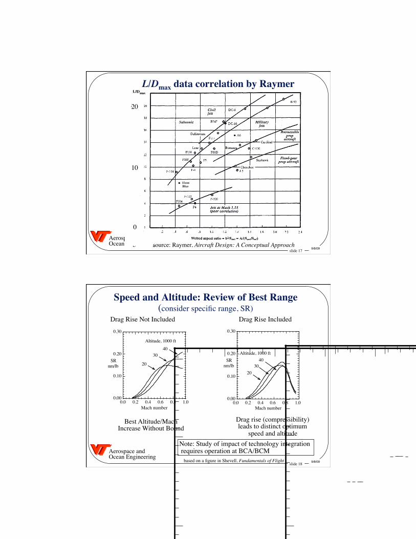
L/Dmax data correlation by Raymer
source: Raymer, Aircraft Design: A Conceptual Approach
10
20
0
slide 18 9/8/09
Aerospace and Ocean Engineering
Speed and Altitude: Review of Best Range �(consider specific range, SR)
based on a figure in Shevell, Fundamentals of Flight
Drag Rise Not Included Drag Rise Included
Best Altitude/Mach Increase Without Bound
Drag rise (compressibility) leads to distinct optimum
speed and altitude Note: Study of impact of technology integration requires operation at BCA/BCM
0.00
0.10
0.20
0.30
0.0 0.2 0.4 0.6 0.8 1.0
SRnm/lb
Mach number
4030
20
Altitude, 1000 ft
0.00
0.10
0.20
0.30
0.0 0.2 0.4 0.6 0.8 1.0
SR at 20KSR at 30KSR at 40K
SRnm/lb
Mach number
4030
20
Altitude, 1000 ft
slide 19 9/8/09
Aerospace and Ocean Engineering
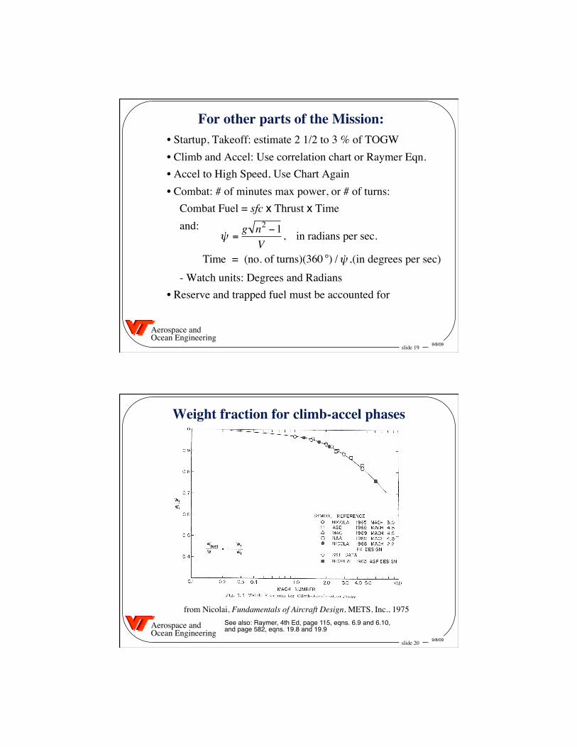
For other parts of the Mission: • Startup, Takeoff: estimate 2 1/2 to 3 % of TOGW • Climb and Accel: Use correlation chart or Raymer Eqn. • Accel to High Speed, Use Chart Again • Combat: # of minutes max power, or # of turns: Combat Fuel = sfc x Thrust x Time and:
- Watch units: Degrees and Radians • Reserve and trapped fuel must be accounted for
˙ ψ =g n2 −1
V, in radians per sec.
Time = (no. of turns)(360 °) / ˙ ψ ,(in degrees per sec)
slide 20 9/8/09
Aerospace and Ocean Engineering
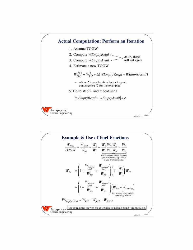
Weight fraction for climb-accel phases
from Nicolai, Fundamentals of Aircraft Design, METS, Inc., 1975 See also: Raymer, 4th Ed, page 115, eqns. 6.9 and 6.10, and page 582, eqns. 19.8 and 19.9
slide 21 9/8/09
Aerospace and Ocean Engineering
Actual Computation: Perform an Iteration 1. Assume TOGW 2. Compute WEmptyReqd 3. Compute WEmptyAvail 4. Estimate a new TOGW
– where Δ is a relaxation factor to speed convergence (2 for the examples)
5. Go to step 2, and repeat until
WEmptyReqd −WEmptyAvail < ε
WTOj+1 =WTO
j + Δ WEmptyReqd −WEmptyAvail( )
At 1st, these will not agree
slide 22 9/8/09
Aerospace and Ocean Engineering
Example & Use of Fuel Fractions
see extra notes on web for extension to include bombs dropped, etc.
WEmptyAvail =WTO −Wfuel −Wfixed
Wfinal
TOGW=Wfinal
WTO
=W8
W1
=W2
W1
W3
W2
W4
W3
⋅ ⋅ ⋅W8
W7
fuel fraction for each segment(must include a step change
if you drop something)
Wfuel = 1+Wreserve
fuel
WTO
+Wtrapped
fuel
WTO
1−W8
W1
WTO
= 1+Wreserve
fuel
WTO
+Wtrapped
fuel
WTO
WTO −WLanding( )ignores any other weight
loss during mission
slide 23 9/8/09
Aerospace and Ocean Engineering
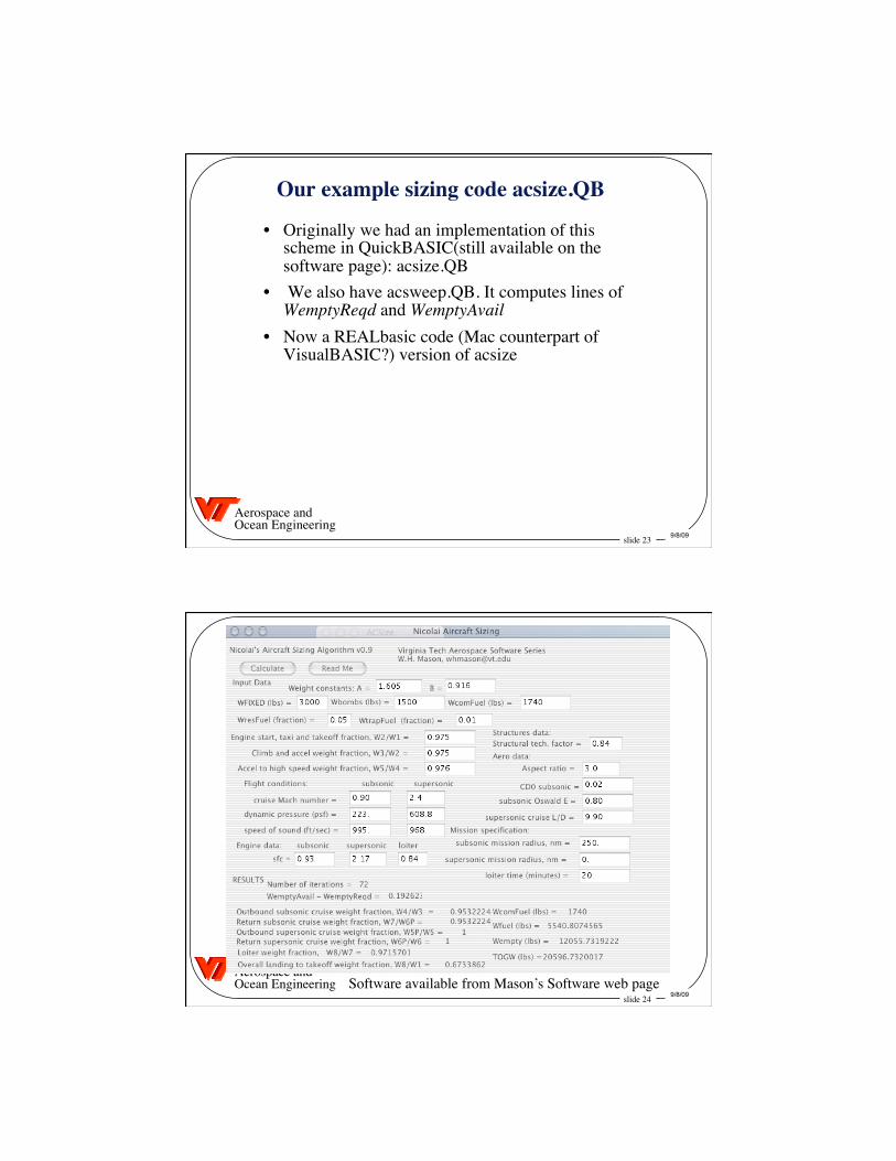
Our example sizing code acsize.QB
• Originally we had an implementation of this scheme in QuickBASIC(still available on the software page): acsize.QB
• We also have acsweep.QB. It computes lines of WemptyReqd and WemptyAvail
• Now a REALbasic code (Mac counterpart of VisualBASIC?) version of acsize
slide 24 9/8/09
Aerospace and Ocean Engineering
Screenshot
Software available from Mason’s Software web page
slide 25 9/8/09
Aerospace and Ocean Engineering
Example:�Nicolai’s Lightweight Fighter
• 250 nm mission radius • 4 minutes of max a/b at M.9, 30K ft • one accel from M = 0.9 to M = 1.6 at 30K ft • 5% reserve fuel • Crew of One • Two AIM 9 missiles, one M-61 cannon • One F100 afterburning turbofan engine
Implies: - L/D cruise = 9 - sfc = 0.93
slide 26 9/8/09
Aerospace and Ocean Engineering
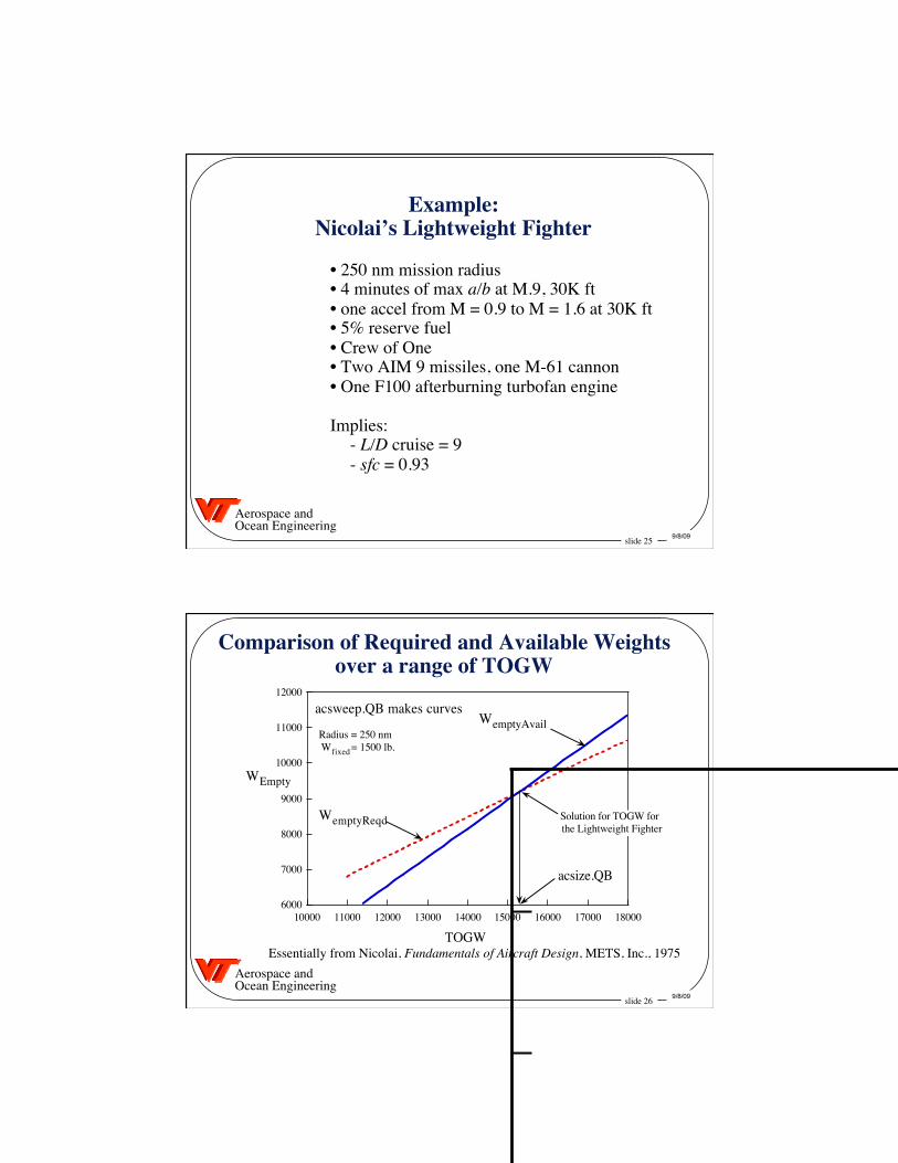
Comparison of Required and Available Weights�over a range of TOGW
Essentially from Nicolai, Fundamentals of Aircraft Design, METS, Inc., 1975
6000
7000
8000
9000
10000
11000
12000
10000 11000 12000 13000 14000 15000 16000 17000 18000
WEmpty
TOGW
Radius = 250 nmWfixed = 1500 lb.
WemptyReqd
WemptyAvail
Solution for TOGW forthe Lightweight Fighter
acsize.QB
acsweep.QB makes curves
slide 27 9/8/09
Aerospace and Ocean Engineering
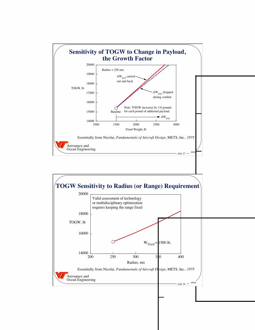
Sensitivity of TOGW to Change in Payload,�the Growth Factor
Essentially from Nicolai, Fundamentals of Aircraft Design, METS, Inc., 1975
14000
15000
16000
17000
18000
19000
20000
1000 1500 2000 2500 3000
TOGW, lb
Fixed Weight, lb
Baseline
Radius = 250 nm
ΔWpay carriedout and back
ΔWpay droppedduring combat
ΔWpay
Note: TOGW increases by 3.8 poundsfor each pound of addtional payload
slide 28 9/8/09
Aerospace and Ocean Engineering
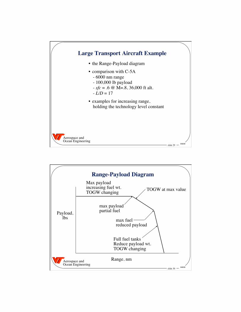
TOGW Sensitivity to Radius (or Range) Requirement
Essentially from Nicolai, Fundamentals of Aircraft Design, METS, Inc., 1975
14000
16000
18000
20000
200 250 300 350 400
TOGW, lb
Radius, nm
Wfixed = 1500 lb.
Valid assessment of technologyor multidisciplinary optimizationrequires keeping the range fixed
slide 29 9/8/09
Aerospace and Ocean Engineering
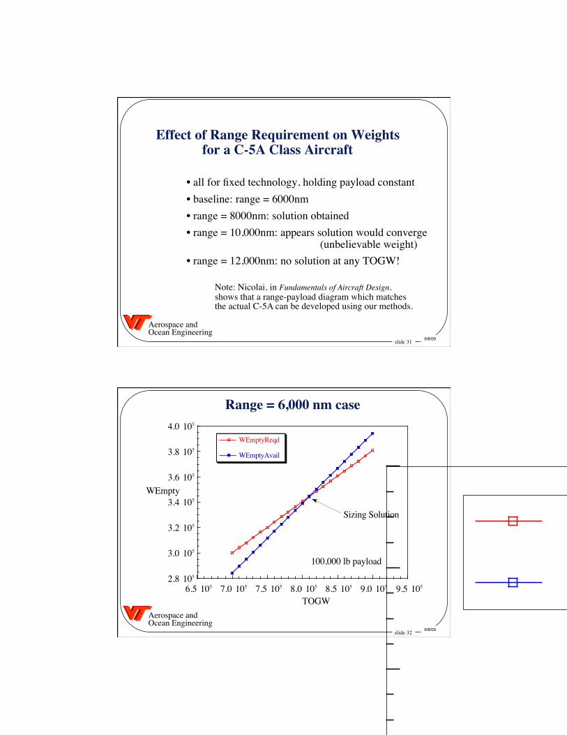
Large Transport Aircraft Example • the Range-Payload diagram
• comparison with C-5A - 6000 nm range - 100,000 lb payload - sfc = .6 @ M=.8, 36,000 ft alt. - L/D = 17
• examples for increasing range, holding the technology level constant
slide 30 9/8/09
Aerospace and Ocean Engineering
Range-Payload Diagram
Payload, lbs
Range, nm
Full fuel tanks Reduce payload wt. TOGW changing
Max payload increasing fuel wt. TOGW changing TOGW at max value
max payload partial fuel
max fuel reduced payload
slide 31 9/8/09
Aerospace and Ocean Engineering
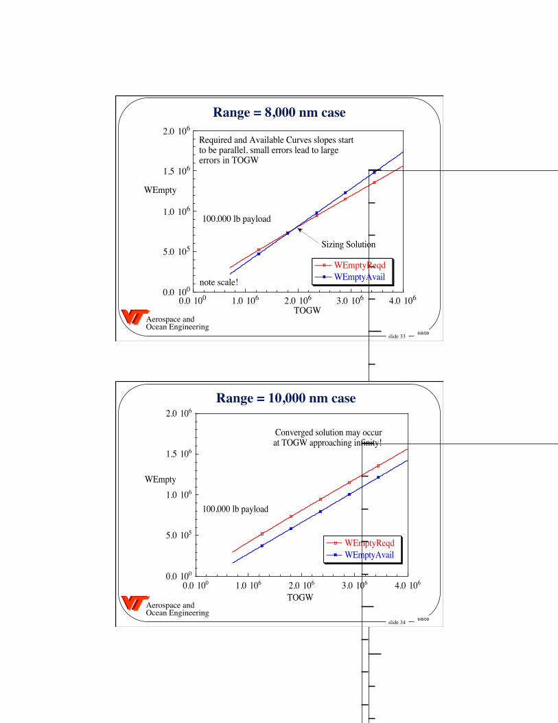
Effect of Range Requirement on Weights�for a C-5A Class Aircraft
• all for fixed technology, holding payload constant • baseline: range = 6000nm • range = 8000nm: solution obtained • range = 10,000nm: appears solution would converge (unbelievable weight)
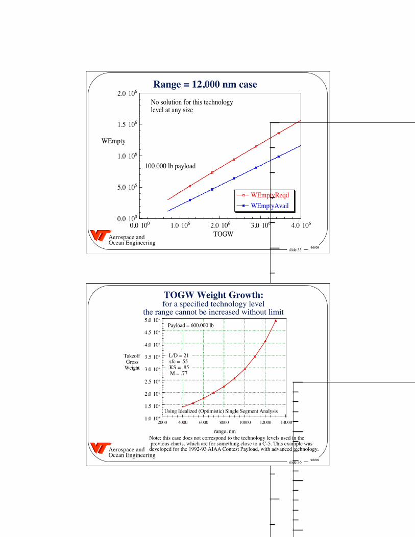
• range = 12,000nm: no solution at any TOGW!
Note: Nicolai, in Fundamentals of Aircraft Design, shows that a range-payload diagram which matches the actual C-5A can be developed using our methods.
slide 32 9/8/09
Aerospace and Ocean Engineering
Range = 6,000 nm case
2.8 105
3.0 105
3.2 105
3.4 105
3.6 105
3.8 105
4.0 105
WEmpty
6.5 105 7.0 105 7.5 105 8.0 105 8.5 105 9.0 105 9.5 105
TOGW
WEmptyReqd
WEmptyAvail
100,000 lb payload
Sizing Solution
slide 33 9/8/09
Aerospace and Ocean Engineering
Range = 8,000 nm case
0.0 100
5.0 105
1.0 106
1.5 106
2.0 106
0.0 100 1.0 106
WEmpty
2.0 106 3.0 106 4.0 106
Sizing Solution
Required and Available Curves slopes startto be parallel, small errors lead to largeerrors in TOGW
note scale!
TOGW
100,000 lb payload
WEmptyReqdWEmptyAvail
slide 34 9/8/09
Aerospace and Ocean Engineering
Range = 10,000 nm case
0.0 100
5.0 105
1.0 106
1.5 106
2.0 106
0.0 100 1.0 106
WEmpty
2.0 106 3.0 106 4.0 106
WEmptyReqdWEmptyAvail
Converged solution may occurat TOGW approaching infinity!
TOGW
100,000 lb payload
slide 35 9/8/09
Aerospace and Ocean Engineering
Range = 12,000 nm case
0.0 100
5.0 105
1.0 106
1.5 106
2.0 106
0.0 100 1.0 106
WEmpty
2.0 106 3.0 106 4.0 106
WEmptyReqdWEmptyAvail
No solution for this technologylevel at any size
TOGW
100,000 lb payload
slide 36 9/8/09
Aerospace and Ocean Engineering
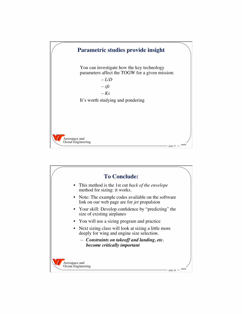
TOGW Weight Growth:�for a specified technology level�
the range cannot be increased without limit
1.0 106
1.5 106
2.0 106
2.5 106
3.0 106
3.5 106
4.0 106
4.5 106
5.0 106
TakeoffGross
Weight
2000 4000 6000 8000 10000 12000 14000
range, nm
L/D = 21sfc = .55KS = .85M = .77
Payload = 600,000 lb
Using Idealized (Optimistic) Single Segment Analysis
Note: this case does not correspond to the technology levels used in the previous charts, which are for something close to a C-5. This example was developed for the 1992-93 AIAA Contest Payload, with advanced technology.
slide 37 9/8/09
Aerospace and Ocean Engineering
Parametric studies provide insight
You can investigate how the key technology parameters affect the TOGW for a given mission:
– L/D – sfc – Ks
It’s worth studying and pondering
slide 38 9/8/09
Aerospace and Ocean Engineering
To Conclude: • This method is the 1st cut back of the envelope
method for sizing: it works. • Note: The example codes available on the software
link on our web page are for jet propulsion • Your skill: Develop confidence by “predicting” the
size of existing airplanes • You will use a sizing program and practice • Next sizing class will look at sizing a little more
deeply for wing and engine size selection. – Constraints on takeoff and landing, etc.
become critically important
Recommended