Air Traffic Controller Cyber Attack Evaluation Serious Game
(ACES)
Systems/Subsystem Specification 9 May 2014
Spring Semester 2014
OR/SYST 699 Capstone Project George Mason University
Fairfax, Virginia

ACES SSS i V140509
THIS PAGE INTENTIONALLY LEFT BLANK
ACES SSS ii V140509
SIGNATURE PAGE
Submitted by ________________________________________________________ Date: ______________________ Doran Cavett
MSSE Candidate, SEOR Team
Submitted by ________________________________________________________ Date: ______________________ Imran Shah MSOR Candidate, SEOR Team
Submitted by ________________________________________________________ Date: ______________________ Wilbert C. Fontan, P.E. MSSE Candidate, SEOR Team
Concurred by ________________________________________________________ Date: ______________________ Paulo CG Costa, PhD
Sponsor, GMU C4I Center
Concurred by ________________________________________________________ Date: ______________________ Christopher Ondrus, PhD
Sponsor, GMU Simulation & Game Institute
Approved by ________________________________________________________ Date: ______________________ Kathryn Blackmond Laskey, PhD
Professor, OR/SYST 699
ACES SSS iii V140509
Table of Contents TABLE OF CONTENTS .............................................................................................................................................. III TABLE OF FIGURES ................................................................................................................................................... IV 1 INTRODUCTION .................................................................................................................................................... 1
1.1 IDENTIFICATION ................................................................................................................................................. 1 1.2 SYSTEM OVERVIEW ............................................................................................................................................. 1
1.2.1 ACES Need ............................................................................................................................................... 1 1.2.2 ACES Context ........................................................................................................................................... 2
1.3 DOCUMENT OVERVIEW ....................................................................................................................................... 3 1.4 CONCEPT OF OPERATIONS ................................................................................................................................... 3 1.5 OVERVIEW OF FUNCTIONALITY ............................................................................................................................ 3
1.5.1 Primary Subsystems (Functional Requirements) .................................................................................. 3 1.5.2 Non-‐Functional Requirements .............................................................................................................. 14
1.6 ACES MODELS ................................................................................................................................................. 15 1.6.1 Use Cases ................................................................................................................................................ 15 1.6.2 State Transition Diagram ..................................................................................................................... 23
2 APPLICABLE DOCUMENTS ............................................................................................................................... 25 3 OBJECTIVE HIERARCHY .................................................................................................................................... 26
3.1 DEVELOPMENT AND SCHEDULE REQUIREMENTS ................................................................................................. 26 3.1.1 Development Period .............................................................................................................................. 26 3.1.2 Completion Date .................................................................................................................................... 26
4 APPENDICES ........................................................................................................................................................ 27 A.2 ACRONYMS ...................................................................................................................................................... 29
ACES SSS iv V140509
Table of Figures Figure 1 -‐ ADS-‐B Communication ....................................... 1 Figure 2 -‐ ACES Subsystem Diagram ..................................... 2 Figure 3 -‐ ACES High Level IO Diagram ................................... 3 Figure 4 – Simulation-‐Emulation Scenario ................................. 8 Figure 5 -‐ Use Case 1: Launching ACES ................................... 16 Figure 6 -‐ Use Case 2: ACCOUNT INITIATION State .......................... 17 Figure 7 -‐ Use Case 3: USER CHECK State ................................. 18 Figure 8 -‐ Use Case 4: OPENING SEQUENCE State ........................... 19 Figure 9 -‐ Use Case 5: PAUSE & RESUME State ............................. 20 Figure 10 -‐ Use Case 6: Save & Quit State ................................. 21 Figure 11 -‐ Use Case 7: HELP / UTILITIES States ............................ 22 Figure 12 -‐ Use Case 7: STATISTICS & SCORES States ........................ 23 Figure 13 -‐ ACES State Transition Diagram ................................ 24 Figure 14 -‐ ACES Objective Hierarchy ................................... 26
ACES SSS V140509
1
1 INTRODUCTION 1.1 Identification This System / Subsystem Specification (SSS) describes the requirements for the Air Traffic Controller Cyber Attack Evaluation Serious Game (hereon referred to as “ACES” or “the ACES game”). This document will be approved by GMU’s C4I Center and Serious Game Institute sponsors and will then serve as the complete set of requirements necessary for ACES to continue into future stages of development. After submission of this SSS, approved individuals can only make changes to this document or those that have been appointed by the sponsor(s) of the document.
1.2 System Overview This section provides a brief overview of the necessity for ACES. It then briefly examines ACES’ structure and its interaction with the environment through a context diagram.
1.2.1 ACES Need
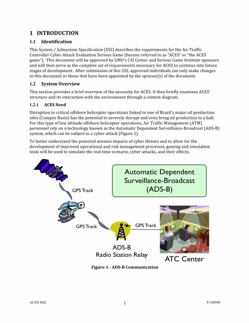
Disruption to critical offshore helicopter operations linked to one of Brazil’s major oil production sites (Campos Basin) has the potential to severely disrupt and even bring oil production to a halt. For this type of low altitude offshore helicopter operations, Air Traffic Management (ATM) personnel rely on a technology known as the Automatic Dependent Surveillance-‐Broadcast (ADS-‐B) system, which can be subject to a cyber-‐attack (Figure 1).
To better understand the potential mission impacts of cyber threats and to allow for the development of improved operational and risk management processes, gaming and simulation tools will be used to simulate the real-‐time scenario, cyber-‐attacks, and their effects.
Figure 1 -‐ ADS-‐B Communication
Paulo Cesar G Costa, Ph.D. NG University Tech Show - Nov 5, 2013
Case Study – ADS-B
!7
GPS Track
GPS Track GPS Track
ADS-B !Radio Station Relay
ATC Center
Automatic Dependent Surveillance-Broadcast!
(ADS-B)
ACES SSS V140509
2
1.2.2 ACES Context
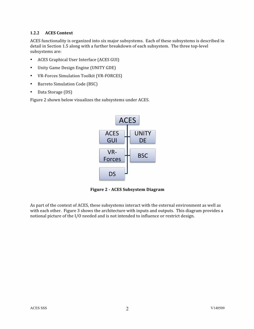
ACES functionality is organized into six major subsystems. Each of these subsystems is described in detail in Section 1.5 along with a further breakdown of each subsystem. The three top-‐level subsystems are:
• ACES Graphical User Interface (ACES GUI)
• Unity Game Design Engine (UNITY GDE)
• VR-‐Forces Simulation Toolkit (VR-‐FORCES)
• Barreto Simulation Code (BSC)
• Data Storage (DS)
Figure 2 shown below visualizes the subsystems under ACES.
Figure 2 -‐ ACES Subsystem Diagram
As part of the context of ACES, these subsystems interact with the external environment as well as with each other. Figure 3 shows the architecture with inputs and outputs. This diagram provides a notional picture of the I/O needed and is not intended to influence or restrict design.
ACES ACES GUI
UNITY DE
VR-‐Forces BSC
DS

ACES SSS V140509
3
Figure 3 -‐ ACES High Level IO Diagram
1.3 Document Overview This document was generated in response to the ACES Proposal developed by the SEOR Team and distributed on April 9, 2014.
This SSS contains all the requirements necessary to design and build the ACES in full compliance with the requirements and expectations of the SEOR Team.
1.4 Concept of Operations ACES will provide a venue for training of air traffic controllers and understanding the impact of cyber-‐attacks on critical infrastructure and operations which will in turn help to identify and prepare mitigating actions.
ACES will provide a means to evaluate various types of cyber-‐attacks against offshore helicopter operations without the need for large investments in real world test scenarios and potential harm or loss of life.
More details can be found in the ACES Concept of Operations document dated May 5th, 2014.
1.5 Overview of Functionality This section provides a brief explanation of the functional components of the ACES.
1.5.1 Primary Subsystems (Functional Requirements)
In this section, descriptions of the primary subsystems are provided in order to gain a better understanding of how each of the subsystems contributes to the overall functionality of the system.
ACES SSS V140509
4
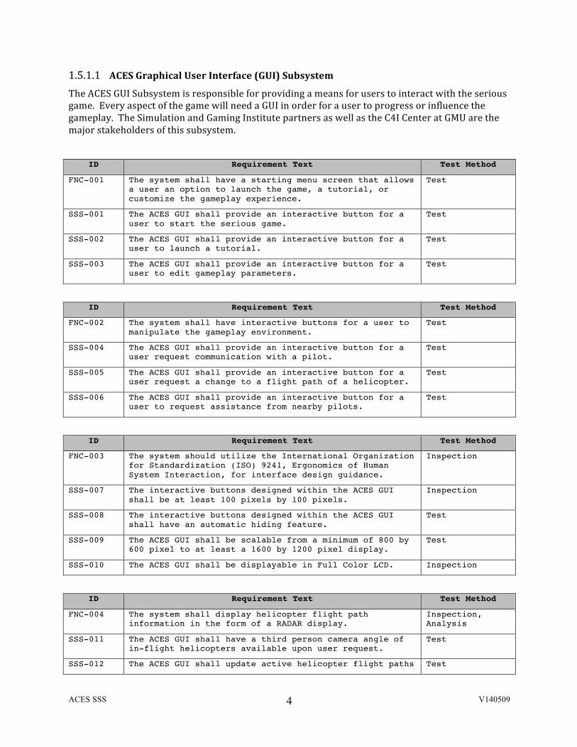
1.5.1.1 ACES Graphical User Interface (GUI) Subsystem The ACES GUI Subsystem is responsible for providing a means for users to interact with the serious game. Every aspect of the game will need a GUI in order for a user to progress or influence the gameplay. The Simulation and Gaming Institute partners as well as the C4I Center at GMU are the major stakeholders of this subsystem.
ID Requirement Text Test Method
FNC-001 The system shall have a starting menu screen that allows a user an option to launch the game, a tutorial, or customize the gameplay experience.
Test
SSS-001 The ACES GUI shall provide an interactive button for a user to start the serious game.
Test
SSS-002 The ACES GUI shall provide an interactive button for a user to launch a tutorial.
Test
SSS-003 The ACES GUI shall provide an interactive button for a user to edit gameplay parameters.
Test
ID Requirement Text Test Method
FNC-002 The system shall have interactive buttons for a user to manipulate the gameplay environment.
Test
SSS-004 The ACES GUI shall provide an interactive button for a user request communication with a pilot.
Test
SSS-005 The ACES GUI shall provide an interactive button for a user request a change to a flight path of a helicopter.
Test
SSS-006 The ACES GUI shall provide an interactive button for a user to request assistance from nearby pilots.
Test
ID Requirement Text Test Method
FNC-003 The system should utilize the International Organization for Standardization (ISO) 9241, Ergonomics of Human System Interaction, for interface design guidance.
Inspection
SSS-007 The interactive buttons designed within the ACES GUI shall be at least 100 pixels by 100 pixels.
Inspection
SSS-008 The interactive buttons designed within the ACES GUI shall have an automatic hiding feature.
Test
SSS-009 The ACES GUI shall be scalable from a minimum of 800 by 600 pixel to at least a 1600 by 1200 pixel display.
Test
SSS-010 The ACES GUI shall be displayable in Full Color LCD. Inspection
ID Requirement Text Test Method
FNC-004 The system shall display helicopter flight path information in the form of a RADAR display.
Inspection, Analysis
SSS-011 The ACES GUI shall have a third person camera angle of in-flight helicopters available upon user request.
Test
SSS-012 The ACES GUI shall update active helicopter flight paths Test

ACES SSS V140509
5
at least every 1 second.
SSS-013 Each helicopter displayed on the ACES GUI shall have a unique aircraft call-sign.
Test
SSS-014 Each aircraft displayed on the ACES GUI shall have a visual representation of its altitude displayed in feet from sea level.
Test
SSS-015 Each aircraft displayed on the ACES GUI shall have its airspeed displayed in knots
Test
SSS-016 Upon a user selection the ACES GUI shall display an aircraft’s unique call-sign.
Test
SSS-017 Upon a user selection the ACES GUI shall display an aircraft’s altitude.
Test
SSS-018 Upon a user selection the ACES GUI shall display an aircraft’s speed in knots.
Test
SSS-019 The ACES GUI shall support display of at least 100 aircraft tracks.
Test
SSS-020 The ACES GUI shall be capable of displaying the position of at least four ADS-B Towers.
Test
SSS-021 The ACES GUI shall provide a coverage area of 50 nautical miles for each ADS-B Tower.
Inspection
ID Requirement Text Test Method
FNC-005 The system shall have a gaming environment that resembles that of an Air Traffic Control Tower.
Inspection
SSS-022 The Air Traffic Control Tower modeled for ACES shall have desks designed and laid out within the structure.
Inspection
SSS-023 The Air Traffic Control Tower modeled for ACES shall have a computer displays designed and laid out within the structure.
Inspection
SSS-024 The Air Traffic Control Tower modeled for ACES shall have keyboards designed and laid out within the structure.
Inspection
SSS-025 The Air Traffic Control Tower modeled for ACES shall have windows designed and laid out within the structure.
Inspection
SSS-026 The Air Traffic Control Tower modeled for ACES shall have computer mice designed and laid out within the structure.
Inspection
SSS-027 The Air Traffic Control Tower modeled for ACES shall have desk chairs designed and laid out within the structure.
Inspection
SSS-028 The Air Traffic Control Tower modeled for ACES shall have keyboards designed and laid out within the structure.
Inspection
SSS-029 The Air Traffic Control Tower modeled for ACES shall have a hallway designed and laid out within the structure that leads to the Control Room.
Inspection
SSS-030 The Air Traffic Control Tower modeled for ACES shall have a stairwell designed and laid out within the
Inspection

ACES SSS V140509
6
structure that leads to the hallway.
ID Requirement Text Test Method
FNC-006
The system shall have a REGISTER menu screen that allows a user to register a new account, import or export registration account data, or to delete a registered account
Test
SSS-031 The ACES GUI shall provide an interactive button for a user to register a new account by imputing necessary data
Test
SSS-032 The ACES GUI shall provide an interactive button for a user to register a new account by importing registration data
Test
SSS-033 The ACES GUI shall provide an interactive button for a user to export account registration data Test
SSS-034 The ACES GUI shall provide an interactive button for a user to delete a registered account Test
ID Requirement Text Test Method
FNC-007 The system shall have a FILE menu screen that allows a user to start, pause, resume, save, quit, import or export a game
Test
SSS-035 The ACES GUI shall provide an interactive button for a user to start a game Test
SSS-036 The ACES GUI shall provide an interactive button for a user to pause a game Test
SSS-037 The ACES GUI shall provide an interactive button for a user to resume a game Test
SSS-038 The ACES GUI shall provide an interactive button for a user to save a game Test
SSS-039 The ACES GUI shall provide an interactive button for a user to quit a game Test
SSS-040 The ACES GUI shall provide an interactive button for a user to import a game Test
SSS-041 The ACES GUI shall provide an interactive button for a user to export a game Test
ID Requirement Text Test Method
FNC-008 The system shall have a EDIT menu screen that allows a user to edit user’s personal information, to customize gameplay parameters
Test
SSS-042 The ACES GUI shall provide an interactive button for a user to edit player’s personal information Test
SSS-043 The ACES GUI shall provide an interactive button for a user to edit gameplay parameters Test
ID Requirement Text Test Method
FNC-009 The system shall have a HELP menu screen that allows a user an option to seek help on how to use ACES Test
SSS-044 The ACES GUI shall provide an interactive button for a user to launch a tutorial module Test
ID Requirement Text Test Method
FNC-010 The system shall have an ANALYSIS menu screen that allows a user an option to assess player’s game-ability status and progress to-date
Test
SSS-045 The ACES GUI shall provide an interactive button for Test
ACES SSS V140509
7
ID Requirement Text Test Method a user to display user’s game results
SSS-046 The ACES GUI shall provide an interactive button for a user to display user’s progress to-date Test
ID Requirement Text Test Method
FNC-011 The system shall utilize controls/widgets and interaction elements to allow user interact with ACES games elements.
Demo
SSS-047 The system shall utilize controls/widgets (e.g. windows, buttons, drop-down list) to allow user interact with ACES games elements.
Demo
SSS-048 The system shall utilize interaction elements (e.g. cursor, pointer) to allow user interact with ACES games elements.
Demo
SSS-049 The system shall provide a user with a means to take a screen capture of the gameplay. Test
ID Requirement Text Test Method
FUN-012 The system shall utilize interaction techniques to resemble real-time Air Traffic Management (ATM) evolutions.
Test
SSS-050
The system shall utilize the mouse and one-key strokes to allow user interact with ACES games elements in an elapsed time comparable to actual ATM voice commands.
Test
SSS-051
The system shall offer multiple user views (e.g. Air Traffic Controller console view, airport tower view) to allow user interact with ACES games elements in an visual manner comparable to actual Air Tower evolutions.
Test
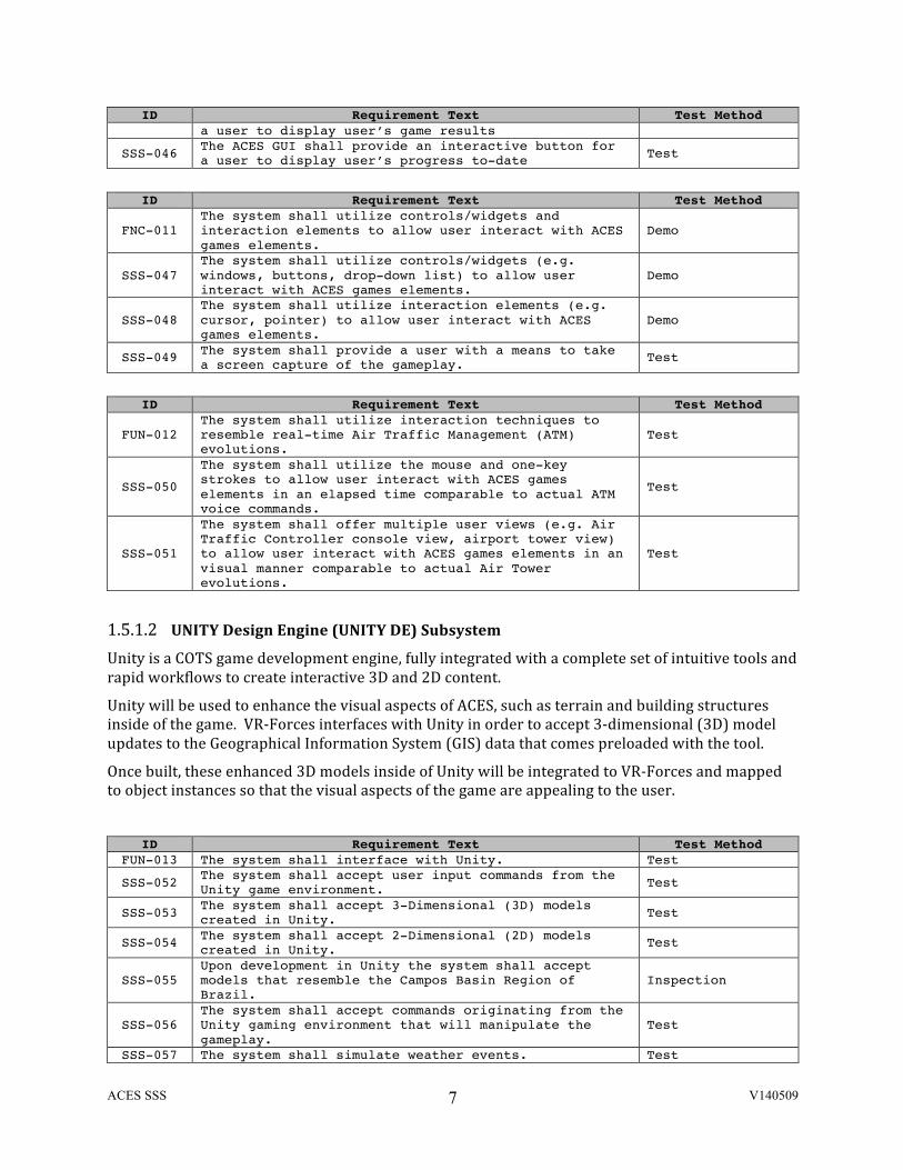
1.5.1.2 UNITY Design Engine (UNITY DE) Subsystem Unity is a COTS game development engine, fully integrated with a complete set of intuitive tools and rapid workflows to create interactive 3D and 2D content.
Unity will be used to enhance the visual aspects of ACES, such as terrain and building structures inside of the game. VR-‐Forces interfaces with Unity in order to accept 3-‐dimensional (3D) model updates to the Geographical Information System (GIS) data that comes preloaded with the tool.
Once built, these enhanced 3D models inside of Unity will be integrated to VR-‐Forces and mapped to object instances so that the visual aspects of the game are appealing to the user.
ID Requirement Text Test Method
FUN-013 The system shall interface with Unity. Test
SSS-052 The system shall accept user input commands from the Unity game environment. Test
SSS-053 The system shall accept 3-Dimensional (3D) models created in Unity. Test
SSS-054 The system shall accept 2-Dimensional (2D) models created in Unity. Test
SSS-055 Upon development in Unity the system shall accept models that resemble the Campos Basin Region of Brazil.
Inspection
SSS-056 The system shall accept commands originating from the Unity gaming environment that will manipulate the gameplay.
Test
SSS-057 The system shall simulate weather events. Test

ACES SSS V140509
8
ID Requirement Text Test Method Note: Weather events encapsulate such experiences as thunderstorms, hurricanes, extreme temperature fluctuations, rough seas, and snow.
1.5.1.3 C2 Collaborative Research Testbed (C2 CRT) Subsystem To build the ACES game prototype the SE/OR-‐SGI team shall leverage work previous completed in a joint effort between the GMU C4I Center and the Technological Institute of Aeronautics in Brazil, the Command and Control (C2) Collaborative Research Testbed. The portion of the C2 testbed that will be reused in ACES is a C++ simulation of helicopter operations in the Campos Basin region developed by Dr. Alexandre Barreto in the Fall of 2013. The C++ simulation code is run as a simulation scenario in the MAK VR-‐Forces simulation tool. The COTS tools used within ACES consists of a number of different components to simulate cyber-‐attacks on a C2 environment:
(1) MAK VR-‐Forces – Simulates helicopter operations (2) LTC Barreto Simulation Code – Previous simulation work that optimized throughput of
helicopter operations in the Campos Basin Region (3) Interfaces to allow components to communicate
Figure 4 – Simulation-‐Emulation Scenario
We plan to leverage this work by researching the Application Programming Interfaces (APIs) for the components, specifically the VR-‐Forces application and the Cyber Attack & IT Effects Generator. This is to understand which messages, operations, and classes will need to be utilized in order to
ACES SSS V140509
9
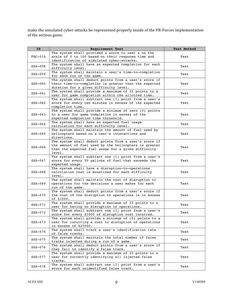
make the simulated cyber-‐attacks be represented properly inside of the VR-‐Forces implementation of the serious game.
ID Requirement Text Test Method
FNC-014 The system shall provided a score to user a on the scale of 0 to 100 based on their response time and identification of simulated cyber-attacks.
Test
SSS-058 The system shall have an expected completion for each difficulty level. Test
SSS-059 The system shall maintain a user’s time-to-completion for each run of the game. Test
SSS-060 The system shall deduct points from a user’s score if their time-to-completion is greater than the expected duration for a given difficulty level.
Test
SSS-061 The system shall provide a maximum of 25 points to a user for game completion within the allotted time. Test
SSS-062 The system shall subtract one (1) point from a user’s score for every two minutes in excess of the expected completion time.
Test
SSS-063 The system shall provide a minimum of zero (0) points to a user for game completion in excess of the expected completion time threshold.
Test
SSS-064 The system shall have an expected fuel usage calculation for each difficulty level. Test
SSS-065 The system shall maintain the amount of fuel used by helicopters based on a user’s interactions and directions.
Test
SSS-066
The system shall deduct points from a user’s score if the amount of fuel used by the helicopters is greater than the expected fuel usage for a given difficulty level.
Test
SSS-067 The system shall subtract one (1) point from a user’s score for every 50 gallons of fuel that exceeds the expected usage.
Test
SSS-068 The system shall have a disruption-to-operations calculation that is monetized for each difficulty level.
Test
SSS-069 The system shall maintain the cost of disruption to operations for the decisions a user makes for each run of the game.
Test
SSS-070 The system shall deduct points from a user’s score if the cost of the disruption to operations is in excess of $1000.
Test
SSS-071 The system shall provide a maximum of 25 points to a user for having no disruption to operations. Test
SSS-072 The system shall subtract one (1) point from a user’s score for every $1000 of disruption cost incurred. Test
SSS-073 The system shall provide a minimum of (0) points to a user for incurring a cost to disruption of operations in excess of $25000.
Test
SSS-074 The system shall track a user’s identification rate of false tracks. Test
SSS-075 The system shall maintain the total number of false tracks injected during a run of a game. Test
SSS-076 The system shall deduct points from a user’s score if they fail to identify a false track. Test
SSS-077 The system shall provide a maximum of 25 points to a user for correctly identifying all injected false tracks.
Test
SSS-078 The system shall subtract one (1) point from a user’s score for each unidentified false track. Test
ACES SSS V140509
10
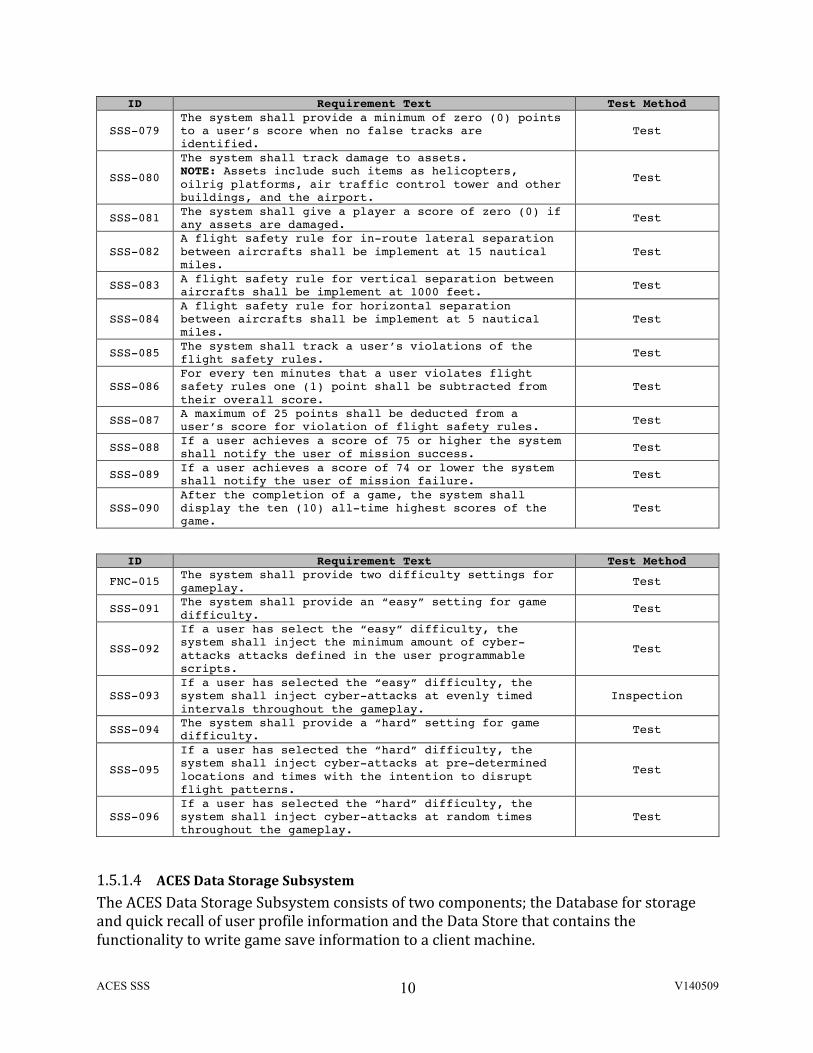
ID Requirement Text Test Method
SSS-079 The system shall provide a minimum of zero (0) points to a user’s score when no false tracks are identified.
Test
SSS-080
The system shall track damage to assets. NOTE: Assets include such items as helicopters, oilrig platforms, air traffic control tower and other buildings, and the airport.
Test
SSS-081 The system shall give a player a score of zero (0) if any assets are damaged. Test
SSS-082 A flight safety rule for in-route lateral separation between aircrafts shall be implement at 15 nautical miles.
Test
SSS-083 A flight safety rule for vertical separation between aircrafts shall be implement at 1000 feet. Test
SSS-084 A flight safety rule for horizontal separation between aircrafts shall be implement at 5 nautical miles.
Test
SSS-085 The system shall track a user’s violations of the flight safety rules. Test
SSS-086 For every ten minutes that a user violates flight safety rules one (1) point shall be subtracted from their overall score.
Test
SSS-087 A maximum of 25 points shall be deducted from a user’s score for violation of flight safety rules. Test
SSS-088 If a user achieves a score of 75 or higher the system shall notify the user of mission success. Test
SSS-089 If a user achieves a score of 74 or lower the system shall notify the user of mission failure. Test
SSS-090 After the completion of a game, the system shall display the ten (10) all-time highest scores of the game.
Test
ID Requirement Text Test Method
FNC-015 The system shall provide two difficulty settings for gameplay. Test
SSS-091 The system shall provide an “easy” setting for game difficulty. Test
SSS-092
If a user has select the “easy” difficulty, the system shall inject the minimum amount of cyber-attacks attacks defined in the user programmable scripts.
Test
SSS-093 If a user has selected the “easy” difficulty, the system shall inject cyber-attacks at evenly timed intervals throughout the gameplay.
Inspection
SSS-094 The system shall provide a “hard” setting for game difficulty. Test
SSS-095
If a user has selected the “hard” difficulty, the system shall inject cyber-attacks at pre-determined locations and times with the intention to disrupt flight patterns.
Test
SSS-096 If a user has selected the “hard” difficulty, the system shall inject cyber-attacks at random times throughout the gameplay.
Test
1.5.1.4 ACES Data Storage Subsystem The ACES Data Storage Subsystem consists of two components; the Database for storage and quick recall of user profile information and the Data Store that contains the functionality to write game save information to a client machine.
ACES SSS V140509
11
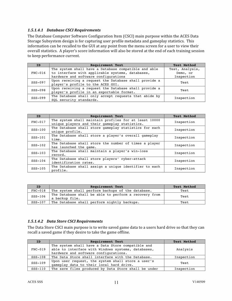
1.5.1.4.1 Database CSCI Requirements The Database Computer Software Configuration Item (CSCI) main purpose within the ACES Data Storage Subsystem design is for capturing user profile metadata and gameplay statistics. This information can be recalled to the GUI at any point from the menu screen for a user to view their overall statistics. A player’s score information will also be stored at the end of each training session to keep performance current.
ID Requirement Text Test Method
FNC-016 The system shall have a Database compatible and able to interface with applicable systems, databases, hardware and software configurations
Test, Analysis, Demo, or
Inspection
SSS-097 Upon receiving a request the Database shall provide a player’s profile to the ACES GUI. Test
SSS-098 Upon receiving a request the Database shall provide a player’s profile in an exportable format. Test
SSS-099 The Database shall only accept requests that abide by SQL security standards. Inspection
ID Requirement Text Test Method
FNC-017 The system shall maintain profiles for at least 10000 unique players and their gameplay statistics. Inspection
SSS-100 The Database shall store gameplay statistics for each unique profile. Inspection
SSS-101 The Database shall store a player’s overall gameplay time. Inspection
SSS-102 The Database shall store the number of times a player has launched the game. Inspection
SSS-103 The Database shall maintain a player’s win-loss record. Inspection
SSS-104 The Database shall store players’ cyber-attack identification rates. Inspection
SSS-105 The Database shall assign a unique identifier to each profile. Inspection
ID Requirement Text Test Method FNC-018 The system shall perform backups of the database. Test
SSS-106 The Database shall be able to perform a recovery from a backup file. Test
SSS-107 The Database shall perform nightly backups. Test
1.5.1.4.2 Data Store CSCI Requirements The Data Store CSCI main purpose is to write saved game data to a users hard drive so that they can recall a saved game if they desire to take the game offline.
ID Requirement Text Test Method
FNC-019 The system shall have a Data Store compatible and able to interface with Windows systems, databases, hardware and software configurations.
Analysis
SSS-108 The Data Store shall interface with the Database. Inspection
SSS-109 Upon user request, the system shall store a user’s gameplay data to their local hard drive. Test
SSS-110 The save files produced by Data Store shall be under Inspection
ACES SSS V140509
12
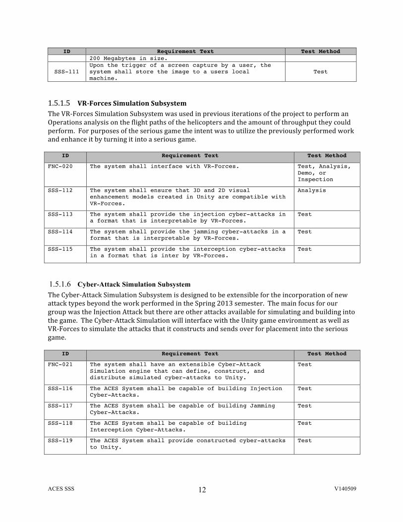
ID Requirement Text Test Method 200 Megabytes in size.
SSS-111 Upon the trigger of a screen capture by a user, the system shall store the image to a users local machine.
Test
1.5.1.5 VR-‐Forces Simulation Subsystem The VR-‐Forces Simulation Subsystem was used in previous iterations of the project to perform an Operations analysis on the flight paths of the helicopters and the amount of throughput they could perform. For purposes of the serious game the intent was to utilize the previously performed work and enhance it by turning it into a serious game.
ID Requirement Text Test Method
FNC-020 The system shall interface with VR-Forces. Test, Analysis, Demo, or Inspection
SSS-112 The system shall ensure that 3D and 2D visual enhancement models created in Unity are compatible with VR-Forces.
Analysis
SSS-113 The system shall provide the injection cyber-attacks in a format that is interpretable by VR-Forces.
Test
SSS-114 The system shall provide the jamming cyber-attacks in a format that is interpretable by VR-Forces.
Test
SSS-115 The system shall provide the interception cyber-attacks in a format that is inter by VR-Forces.
Test
1.5.1.6 Cyber-Attack Simulation Subsystem The Cyber-‐Attack Simulation Subsystem is designed to be extensible for the incorporation of new attack types beyond the work performed in the Spring 2013 semester. The main focus for our group was the Injection Attack but there are other attacks available for simulating and building into the game. The Cyber-‐Attack Simulation will interface with the Unity game environment as well as VR-‐Forces to simulate the attacks that it constructs and sends over for placement into the serious game.
ID Requirement Text Test Method
FNC-021 The system shall have an extensible Cyber-Attack Simulation engine that can define, construct, and distribute simulated cyber-attacks to Unity.
Test
SSS-116 The ACES System shall be capable of building Injection Cyber-Attacks.
Test
SSS-117 The ACES System shall be capable of building Jamming Cyber-Attacks.
Test
SSS-118 The ACES System shall be capable of building Interception Cyber-Attacks.
Test
SSS-119 The ACES System shall provide constructed cyber-attacks to Unity.
Test
ACES SSS V140509
13
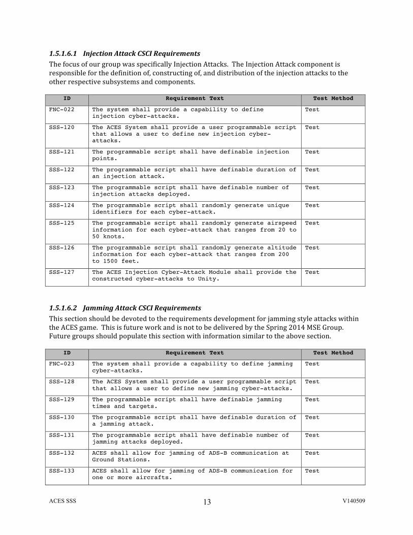
1.5.1.6.1 Injection Attack CSCI Requirements The focus of our group was specifically Injection Attacks. The Injection Attack component is responsible for the definition of, constructing of, and distribution of the injection attacks to the other respective subsystems and components.
ID Requirement Text Test Method
FNC-022 The system shall provide a capability to define injection cyber-attacks.
Test
SSS-120 The ACES System shall provide a user programmable script that allows a user to define new injection cyber-attacks.
Test
SSS-121 The programmable script shall have definable injection points.
Test
SSS-122 The programmable script shall have definable duration of an injection attack.
Test
SSS-123 The programmable script shall have definable number of injection attacks deployed.
Test
SSS-124 The programmable script shall randomly generate unique identifiers for each cyber-attack.
Test
SSS-125 The programmable script shall randomly generate airspeed information for each cyber-attack that ranges from 20 to 50 knots.
Test
SSS-126 The programmable script shall randomly generate altitude information for each cyber-attack that ranges from 200 to 1500 feet.
Test
SSS-127 The ACES Injection Cyber-Attack Module shall provide the constructed cyber-attacks to Unity.
Test
1.5.1.6.2 Jamming Attack CSCI Requirements This section should be devoted to the requirements development for jamming style attacks within the ACES game. This is future work and is not to be delivered by the Spring 2014 MSE Group. Future groups should populate this section with information similar to the above section.
ID Requirement Text Test Method
FNC-023 The system shall provide a capability to define jamming cyber-attacks.
Test
SSS-128 The ACES System shall provide a user programmable script that allows a user to define new jamming cyber-attacks.
Test
SSS-129 The programmable script shall have definable jamming times and targets.
Test
SSS-130 The programmable script shall have definable duration of a jamming attack.
Test
SSS-131 The programmable script shall have definable number of jamming attacks deployed.
Test
SSS-132 ACES shall allow for jamming of ADS-B communication at Ground Stations.
Test
SSS-133 ACES shall allow for jamming of ADS-B communication for one or more aircrafts.
Test
ACES SSS V140509
14
ID Requirement Text Test Method
SSS-134 The ACES Jamming Cyber-Attack Module shall provide the constructed cyber-attacks to Unity.
Test
1.5.1.6.3 Interception Attack CSCI Requirements This section should be devoted to the requirements development for interception style attacks within the ACES game. This is future work and is not to be delivered by the Spring 2014 MSE Group. Future groups should populate this section with information similar to the above section.
ID Requirement Text Test Method
FNC-024 The system shall provide a capability to define ADS-B interception cyber-attacks.
Test
SSS-135 The programmable script shall have definable interception times and targets.
Test
SSS-136 The programmable script shall have definable duration of interception attacks.
Test
SSS-137 The programmable script shall have definable number of interception attacks deployed.
Test
SSS-138 ACES shall allow for interception of ADS-B communication at Ground Stations.
Test
SSS-139 ACES shall allow for interception of aircraft ADS-B communication.
Test
SSS-140 The ACES Interception Cyber-Attack Module shall provide the constructed cyber-attacks to Unity.
Test
1.5.2 Non-‐Functional Requirements
This section contains requirements that are leveed on the system but do not affect the capabilities or functionality of the system. It is mainly focused on environmental and maintainability aspects of the system components.
ID Requirement Text Test Method
SSS-141 The system shall have a MTTR of 2 hours. Analysis
SSS-142 The system shall have a reliability rating of at least 0.98
Analysis
SSS-143 ACES shall be offered in CD or Downloadable forms. Inspection
SSS-144 The system shall cause no physical harm to the player(s).
Inspection
SSS-145 The shipping weight of the CD format of the ACES game shall be no more than 5 pounds (lbs).
Analysis
SSS-146 The shipping volume of the CD shall be less than or equal to 8 inches by 5 inches by 2 inches.
Analysis
SSS-147 The system shall run on commonly available COTS hardware to reduce repair and spares costs.
Analysis
ACES SSS V140509
15
1.6 ACES Models
1.6.1 Use Cases
Each use case examined during the systems definition process is described here in detail. For each use case a brief description is provided along with a listing of actors, the type (either primary or secondary), the scenario, and an accompanying diagram. For some use cases, the triggering event is specified for clarity.
1.6.1.1 Launching ACES (Use Case 1) Actor: Player
Type: Primary
Description: This scenario describes the events that occur during the Launching ACES mode. The player launches ACES and (or eventually) enters userid and password to initiate an ACES session.
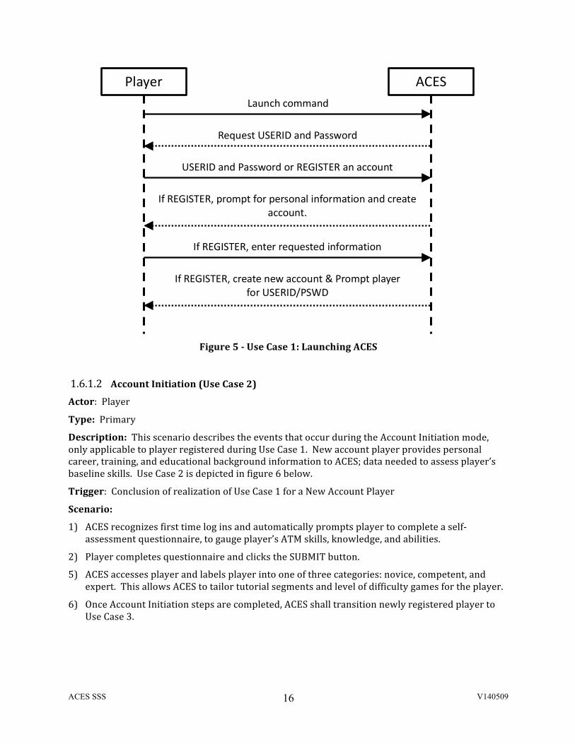
Use Case 1 is depicted in figure 5 below.
Scenario:
1) Player launches the ACES Software Application.
2) If account exists, player access ACES by entering userid and password and clicking SUBMIT button. If not, player clicks on REGISTER and creates new ACES Account. Once completed, the registration window shall automatically re-‐launch LOG-‐IN screen for new player to log-‐in.
3) For existing ACES accounts, ACES shall offer player to move to either Use Case 3 or Use Case 4 (USER CHECK or START a game session, respectively).
4) For new accounts, ACES transitions to Use Case 2.
ACES SSS V140509
16
Figure 5 -‐ Use Case 1: Launching ACES
1.6.1.2 Account Initiation (Use Case 2) Actor: Player
Type: Primary
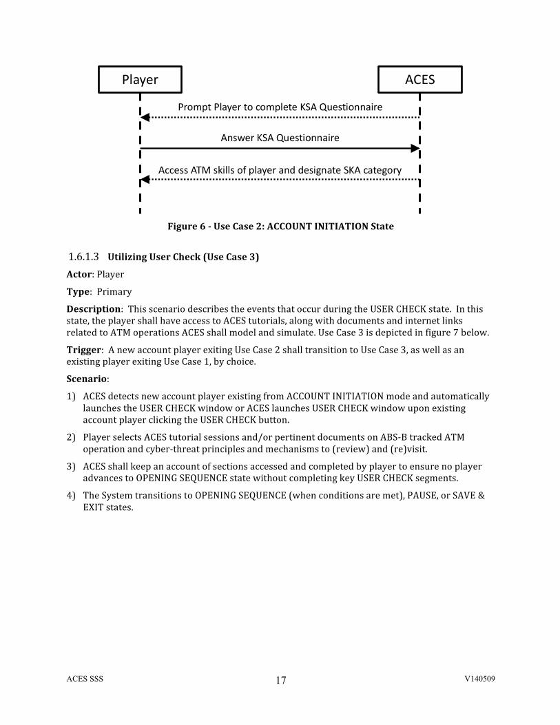
Description: This scenario describes the events that occur during the Account Initiation mode, only applicable to player registered during Use Case 1. New account player provides personal career, training, and educational background information to ACES; data needed to assess player’s baseline skills. Use Case 2 is depicted in figure 6 below.
Trigger: Conclusion of realization of Use Case 1 for a New Account Player
Scenario:
1) ACES recognizes first time log ins and automatically prompts player to complete a self-‐assessment questionnaire, to gauge player’s ATM skills, knowledge, and abilities.
2) Player completes questionnaire and clicks the SUBMIT button.
5) ACES accesses player and labels player into one of three categories: novice, competent, and expert. This allows ACES to tailor tutorial segments and level of difficulty games for the player.
6) Once Account Initiation steps are completed, ACES shall transition newly registered player to Use Case 3.
Player ACES
Launch command
Request USERID and Password
USERID and Password or REGISTER an account
If REGISTER, prompt for personal information and create account.
If REGISTER, enter requested information
If REGISTER, create new account & Prompt player for USERID/PSWD
ACES SSS V140509
17
Figure 6 -‐ Use Case 2: ACCOUNT INITIATION State
1.6.1.3 Utilizing User Check (Use Case 3) Actor: Player
Type: Primary
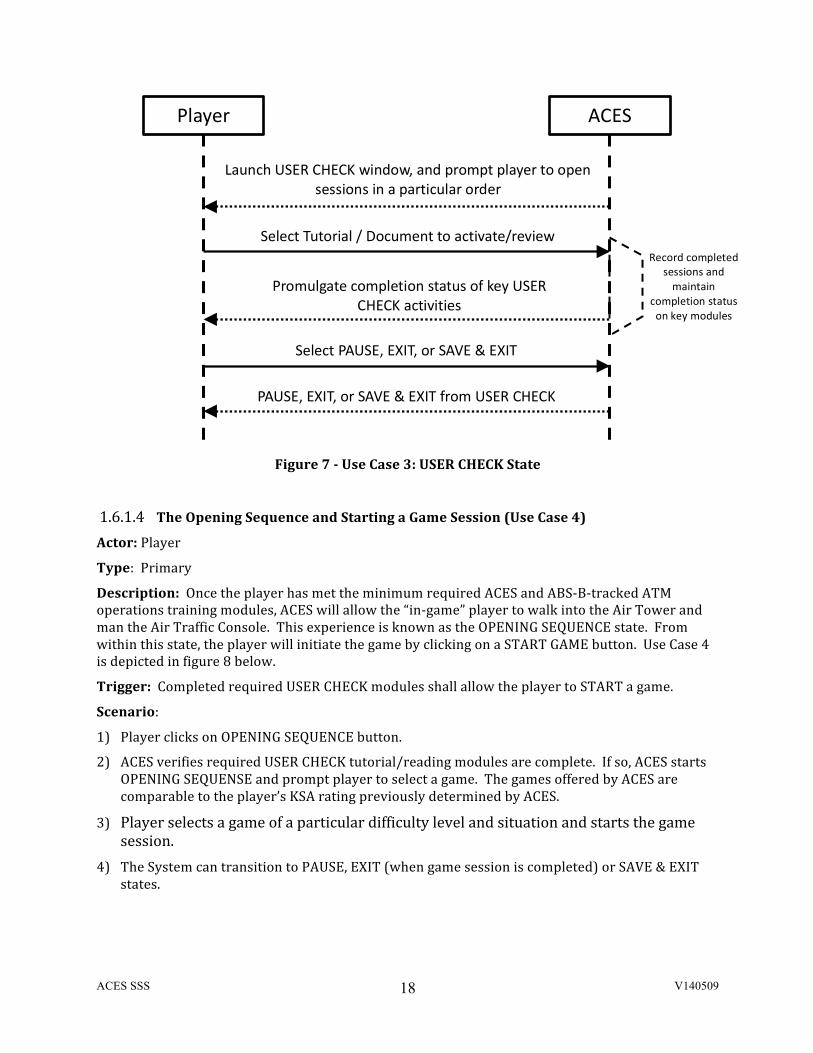
Description: This scenario describes the events that occur during the USER CHECK state. In this state, the player shall have access to ACES tutorials, along with documents and internet links related to ATM operations ACES shall model and simulate. Use Case 3 is depicted in figure 7 below.
Trigger: A new account player exiting Use Case 2 shall transition to Use Case 3, as well as an existing player exiting Use Case 1, by choice.
Scenario:
1) ACES detects new account player existing from ACCOUNT INITIATION mode and automatically launches the USER CHECK window or ACES launches USER CHECK window upon existing account player clicking the USER CHECK button.
2) Player selects ACES tutorial sessions and/or pertinent documents on ABS-‐B tracked ATM operation and cyber-‐threat principles and mechanisms to (review) and (re)visit.
3) ACES shall keep an account of sections accessed and completed by player to ensure no player advances to OPENING SEQUENCE state without completing key USER CHECK segments.
4) The System transitions to OPENING SEQUENCE (when conditions are met), PAUSE, or SAVE & EXIT states.
Player ACES
Prompt Player to complete KSA Questionnaire
Answer KSA Questionnaire
Access ATM skills of player and designate SKA category
ACES SSS V140509
18
Figure 7 -‐ Use Case 3: USER CHECK State
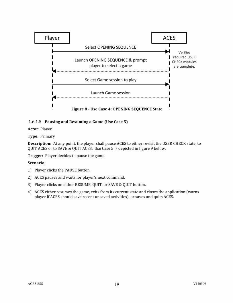
1.6.1.4 The Opening Sequence and Starting a Game Session (Use Case 4) Actor: Player
Type: Primary
Description: Once the player has met the minimum required ACES and ABS-‐B-‐tracked ATM operations training modules, ACES will allow the “in-‐game” player to walk into the Air Tower and man the Air Traffic Console. This experience is known as the OPENING SEQUENCE state. From within this state, the player will initiate the game by clicking on a START GAME button. Use Case 4 is depicted in figure 8 below.
Trigger: Completed required USER CHECK modules shall allow the player to START a game.
Scenario:
1) Player clicks on OPENING SEQUENCE button.
2) ACES verifies required USER CHECK tutorial/reading modules are complete. If so, ACES starts OPENING SEQUENSE and prompt player to select a game. The games offered by ACES are comparable to the player’s KSA rating previously determined by ACES.
3) Player selects a game of a particular difficulty level and situation and starts the game session.
4) The System can transition to PAUSE, EXIT (when game session is completed) or SAVE & EXIT states.
Player ACES
Launch USER CHECK window, and prompt player to open sessions in a particular order
Select Tutorial / Document to activate/review
Promulgate completion status of key USER CHECK activities
PAUSE, EXIT, or SAVE & EXIT from USER CHECK
Select PAUSE, EXIT, or SAVE & EXIT
Record completed sessions and maintain
completion status on key modules
ACES SSS V140509
19
Figure 8 -‐ Use Case 4: OPENING SEQUENCE State
1.6.1.5 Pausing and Resuming a Game (Use Case 5) Actor: Player
Type: Primary
Description: At any point, the player shall pause ACES to either revisit the USER CHECK state, to QUIT ACES or to SAVE & QUIT ACES. Use Case 5 is depicted in figure 9 below.
Trigger: Player decides to pause the game.
Scenario:
1) Player clicks the PAUSE button.
2) ACES pauses and waits for player’s next command.
3) Player clicks on either RESUME, QUIT, or SAVE & QUIT button.
4) ACES either resumes the game, exits from its current state and closes the application (warns player if ACES should save recent unsaved activities), or saves and quits ACES.
Player ACES
Launch OPENING SEQUENCE & prompt player to select a game
Select Game session to play
Launch Game session
Select OPENING SEQUENCE Verifies
required USER CHECK modules are complete.
ACES SSS V140509
20
Figure 9 -‐ Use Case 5: PAUSE & RESUME State
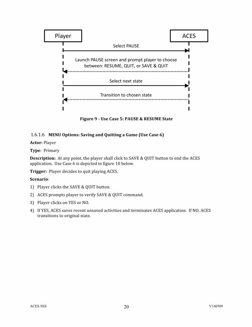
1.6.1.6 MENU Options: Saving and Quitting a Game (Use Case 6) Actor: Player
Type: Primary
Description: At any point, the player shall click to SAVE & QUIT button to end the ACES application. Use Case 6 is depicted in figure 10 below.
Trigger: Player decides to quit playing ACES.
Scenario:
1) Player clicks the SAVE & QUIT button.
2) ACES prompts player to verify SAVE & QUIT command.
3) Player clicks on YES or NO.
4) If YES, ACES saves recent unsaved activities and terminates ACES application. If NO, ACES transitions to original state.
Player ACES
Launch PAUSE screen and prompt player to choose between: RESUME, QUIT, or SAVE & QUIT
Select next state
Transition to chosen state
Select PAUSE
ACES SSS V140509
21
Figure 10 -‐ Use Case 6: Save & Quit State
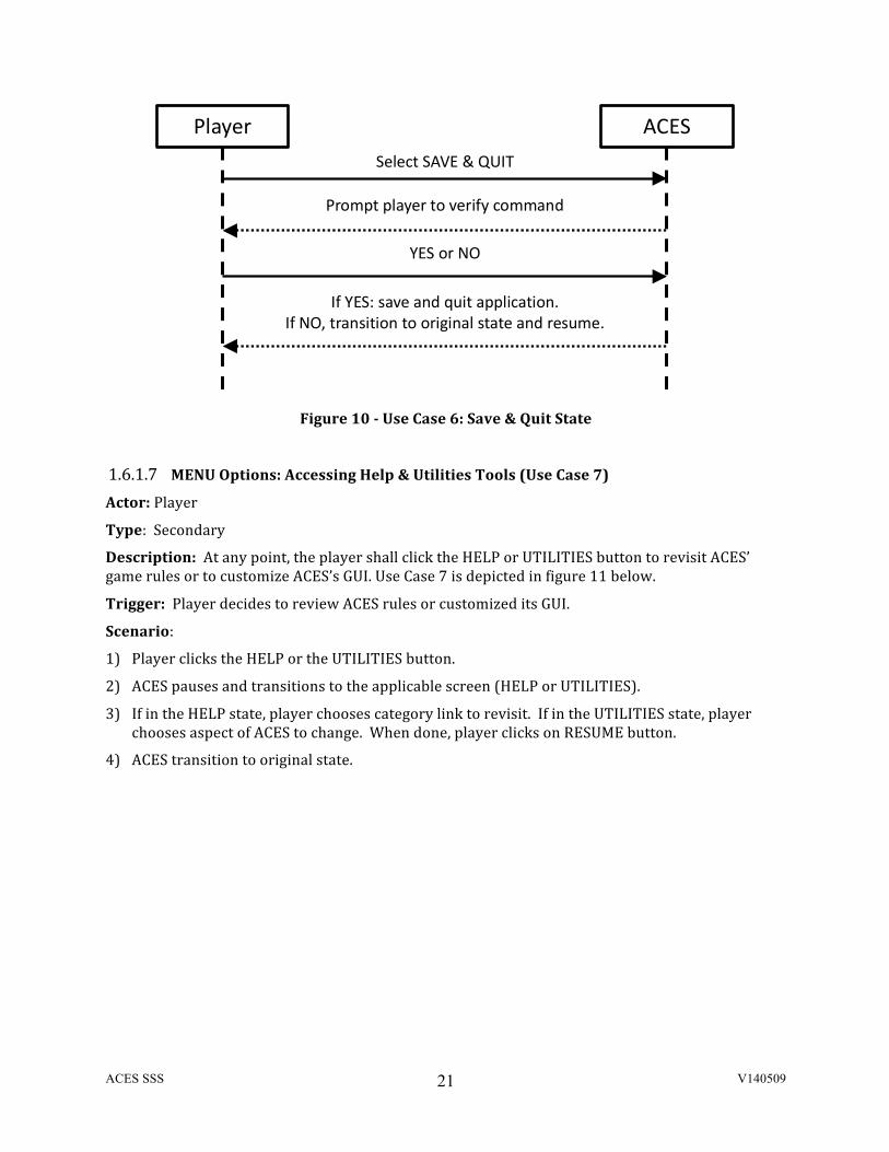
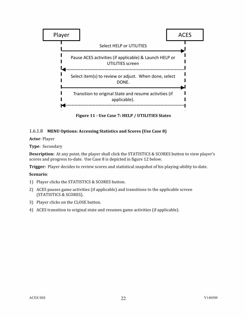
1.6.1.7 MENU Options: Accessing Help & Utilities Tools (Use Case 7) Actor: Player
Type: Secondary
Description: At any point, the player shall click the HELP or UTILITIES button to revisit ACES’ game rules or to customize ACES’s GUI. Use Case 7 is depicted in figure 11 below.
Trigger: Player decides to review ACES rules or customized its GUI.
Scenario:
1) Player clicks the HELP or the UTILITIES button.
2) ACES pauses and transitions to the applicable screen (HELP or UTILITIES).
3) If in the HELP state, player chooses category link to revisit. If in the UTILITIES state, player chooses aspect of ACES to change. When done, player clicks on RESUME button.
4) ACES transition to original state.
Player ACES
Prompt player to verify command
YES or NO
If YES: save and quit application. If NO, transition to original state and resume.
Select SAVE & QUIT
ACES SSS V140509
22
Figure 11 -‐ Use Case 7: HELP / UTILITIES States
1.6.1.8 MENU Options: Accessing Statistics and Scores (Use Case 8)
Actor: Player
Type: Secondary
Description: At any point, the player shall click the STATISTICS & SCORES button to view player’s scores and progress to-‐date. Use Case 8 is depicted in figure 12 below.
Trigger: Player decides to review scores and statistical snapshot of his playing-‐ability to-‐date.
Scenario:
1) Player clicks the STATISTICS & SCORES button.
2) ACES pauses game activities (if applicable) and transitions to the applicable screen (STATISTICS & SCORES).
3) Player clicks on the CLOSE button.
4) ACES transition to original state and resumes game activities (if applicable).
Player ACES
Pause ACES activities (if applicable) & Launch HELP or UTILITIES screen
Select item(s) to review or adjust. When done, select DONE.
Transition to original State and resume activities (if applicable).
Select HELP or UTILITIES

ACES SSS V140509
23
Figure 12 -‐ Use Case 7: STATISTICS & SCORES States
1.6.2 State Transition Diagram
The state transition diagram below (Figure 13) shows the transitions between the states for the ACES. This diagram summarizes how the ACES game moves from one state or mode to another.
The beginning state is the LAUNCH state where the player logs in or creates a new account. For new players, the system goes into the INITIATION state, which is where the GUI menu is present for entering new player’s information and offers a USER CHECK. This check will consist of various tutorials and general description segments of ACES’ components or elements.
After initialization (or after the LAUNCH state for returning players), the ACES game transits to an OPENING SEQUENCE state, where the player eventually chooses the game’s level of difficulty and initiates a game session.
Prior to, during, and after a game session, the player can go to the USER CHECK state to revisit the tutorial and/or general description segments. If the game is in session, ACES will have to go through the PAUSE state before entering to any other state.
When the ACES game session is completed (or paused), ACES can transition to the END GAME state, the USER Check state (as described above), or back to the OPENING SEQUENCE state (to initiate another game session).
Whenever a game session is completed, ACES will momentarily transition into a SUMMARY state to reflect the player’s scores and progress.
Player ACES
Pause ACES activities (if applicable) & Launch HELP or UTILITIES screen
Select Game session to play
Launch Game session
Select STATISTICS & SCORES

ACES SSS V140509
24
Figure 13 -‐ ACES State Transition Diagram
LAUNCH
INITIATION
PAUSE
OPENING SEQUENCE
END
TUTORIAL GENERAL DESCRIPTION
USER CHECK
PAUSE TO REVIEW RULES
RETURN TO PAUSED GAME
RE-‐LAUNCH ACES
EXISTING USER
REVIEWING PRIOR TO NEW GAME
EXISTING USER
NEW USER
NEW USER
AFTER PAUSING, SAVE & END SESSION
PAUSE DURING INITIATION
SAVE AND/OR END
SESSION
ACES SSS V140509
25
2 APPLICABLE DOCUMENTS ACES Proposal v9, dated 9 April, 2014
ACES Concept of Operations, dated 14 April, 2014
PMS Requirements Traceability Matrix (RTM) – Provided as Appendix A3.
ACES SSS V140509
26
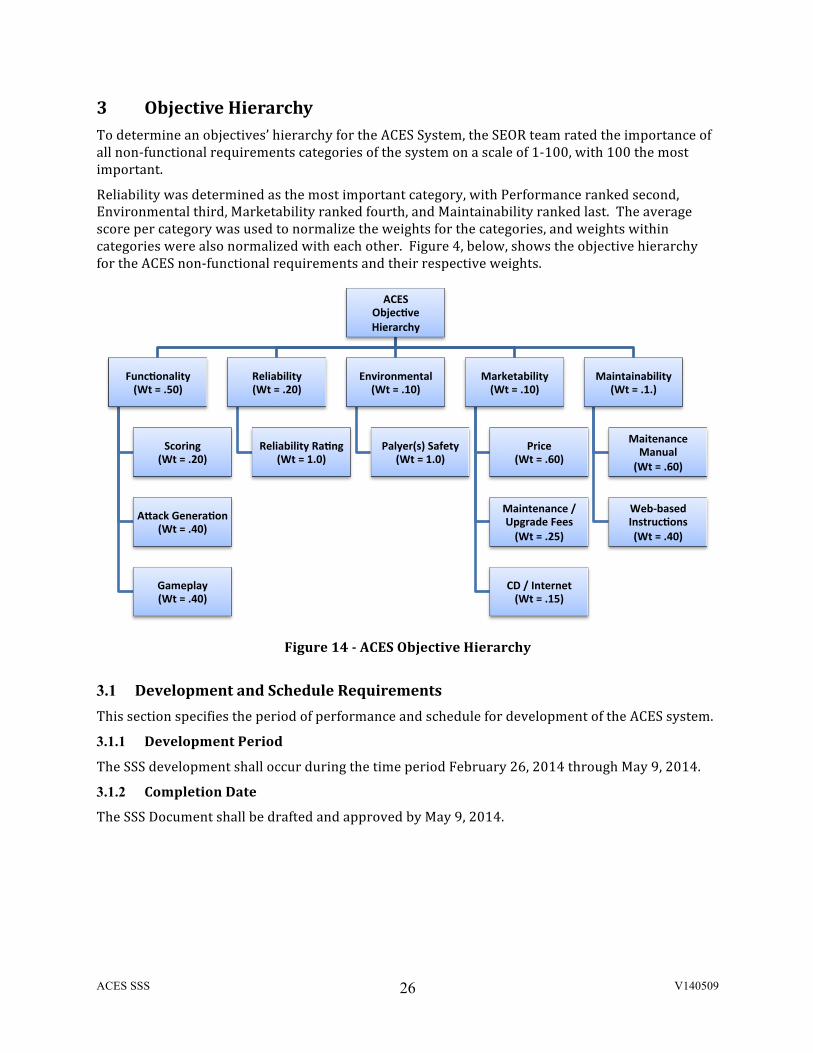
3 Objective Hierarchy To determine an objectives’ hierarchy for the ACES System, the SEOR team rated the importance of all non-‐functional requirements categories of the system on a scale of 1-‐100, with 100 the most important.
Reliability was determined as the most important category, with Performance ranked second, Environmental third, Marketability ranked fourth, and Maintainability ranked last. The average score per category was used to normalize the weights for the categories, and weights within categories were also normalized with each other. Figure 4, below, shows the objective hierarchy for the ACES non-‐functional requirements and their respective weights.
Figure 14 -‐ ACES Objective Hierarchy
3.1 Development and Schedule Requirements This section specifies the period of performance and schedule for development of the ACES system.
3.1.1 Development Period
The SSS development shall occur during the time period February 26, 2014 through May 9, 2014.
3.1.2 Completion Date
The SSS Document shall be drafted and approved by May 9, 2014.
ACES Objec+ve Hierarchy
Maintainability (Wt = .1.)
Maitenance Manual (Wt = .60)
Web-‐based Instruc+ons (Wt = .40)
Marketability (Wt = .10)
Price (Wt = .60)
Maintenance / Upgrade Fees (Wt = .25)
CD / Internet (Wt = .15)
Environmental (Wt = .10)
Palyer(s) Safety (Wt = 1.0)
Reliability (Wt = .20)
Reliability Ra+ng (Wt = 1.0)
Func+onality (Wt = .50)
Scoring (Wt = .20)
ASack Genera+on (Wt = .40)
Gameplay (Wt = .40)
ACES SSS V140509
27
4 APPENDICES
A-‐1 Definitions
A-‐2 Acronyms
ACES SSS V140509
28
A.1 Definitions • Reliability – The capability to maintain a level of performance under stated conditions for a
stated period of time. In the case of the ACES, the system shall perform and function properly (meaning on-‐time and within stated constraints) regarding measurements for 98% of the time it is in use.
• Shall – expresses a requirement that is mandatory.
• Should – expresses a requirement that is important but is somewhat flexible.

ACES SSS V140509
29
A.2 Acronyms ACES Air Traffic Controller Cyber Attack Evaluation Serious (Game)
ATC Air Traffic Controller
ATM Air Traffic Management C4I Command, Control, Communications, Computer, and Information
CSCI Computer Software Configuration Item GMU George Mason University
HW Hardware
HELO Helicopter IA Information Assurance
OA Operational Assessment
OILPLAT Oil Platform OR Operations Research
SE Systems Engineering SME Subject Matter Expert
SOP Standard Operating Procedure
T&E Test & Evaluation
Recommended