Applications of a liquid membrane in
Taylor flow regime (LMTF) on
separation processes and design of
fermentation hybrid systems
Alan Didier Pérez Ávila
Universidad Nacional de Colombia
Facultad de Ingeniería y Arquitectura, Departamento de Ingeniería Química
Manizales, Colombia
2019


Applications of a liquid membrane in
Taylor flow regime (LMTF) on
separation processes and design of
fermentation hybrid systems
Alan Didier Pérez Ávila
Dissertation presented in partial fulfilment of the requirements for the degree of:
Doctor of Engineering Science (Ph.D.) – Chemical Engineering
Advisor:
Ph.D., Javier Fontalvo Alzate
Co-advisor:
Ph.D., Sneyder Rodríguez Barona
Research field:
Process intensification and hybrid systems
Research groups and labs:
Applications of New Technologies Research Group, Laboratory of Process Intensification and
Hybrid Systems
Research Group in Lactic Acid Bacteria and their Biotechnological-Industrial Applications,
Laboratory of Food Science
Universidad Nacional de Colombia
Facultad de Ingeniería y Arquitectura, Departamento Ingeniería Química
Manizales, Colombia
2019


Dedication
To my family. They always have supported me,
believed in me, and encouraged me to achieve my
goals.
To my advisors. They always are teaching me, not
only on science but about life as well.
To my friends. They never let me down and spent
with me nice moments during this journey.

Acknowledgments
I want to give my sincere thanks to every single one of the people who accompanied me during this
journey. My gratitude to my advisor, Professor Javier Fontalvo, and my co-advisor, Professor
Sneyder Rodríguez for their support, advice, patience, teachings, and guidance. They drive me and
help me to find the answers for the understanding of all new findings. Also, they encourage me to
participate in National and International Congresses, which were amazing experiences. Special
thanks to Javier for your confidence, your friendship, because you involved me in the science world,
because you provide me the opportunity to work with you from my times as undergraduate, and
because you always believed on me. You also have encouraged me to grow up both in personal and
scientific aspects.
I would like to thank you to Professor Bart Van der Bruggen which was my advisor during my
internship as a guest researcher in KU Leuven. He always encouraged me and motivated me to move
on with my research. He always has believed in this project and he has supported it openly. I really
appreciate your kind support during my stay in Belgium.
My gratitude, to the peer reviewers of the thesis proposal, the professors, Alberto Claudio Habert
(Universidade Federal do Rio de Janeiro), Daniel Gorri (Universidad de Cantabria), and Óscar Prado
(Universidad Nacional de Colombia). They assessed this research in an early stage and give to us
good advice for its development. Also, they trusted in the scope of this research from those days.
My sincere gratitude to the reviewers of this Ph.D. dissertation and juries during my Ph.D. defense,
the professors Carlos Jesus Muvdi (Universidad Industrial de Santander), Daniel Gorri (Universidad
de Cantabria), and Felipe Bustamante (Universidad de Antioquia), who spend time reading and
qualifying this dissertation. They also provided me with an excellent environment for my Ph.D.
defense, especially in the time where I had to answer the questions from the juries. It was pleasure
and honor to me that all of you were the juries of this research.
I would also like to thank you to everyone who was involved in this project. To Eduvier who suffer
and enjoy with me in several experiments. We support each other during the hard days when it was
too difficult to gets experimental results and we also celebrate the good days when we get good

VIII Applications of a liquid membrane in Taylor flow regime (LMTF) on separation processes and design
of fermentation hybrid system
experimental results. Thank you to Verónica who was like my right hand in a big part of this project.
She helped me and supported me on several experiments. Thanks to Oriana and Diana who also
worked with me in this project. Thanks to Laura who supported me in the last experimental stage of
this research. Thank you to my friend Juan Álvaro. We shared several coffee breaks and spoke about
our research projects. He gave to me good advice when the experiments were not working. Thanks
to Daniel who also accompanied me in the early stage of this project. We support each other in
several experiments both his research and my research. In general, thanks to all the research group
(applications of new technologies group research) and members of the laboratory (process
intensification and hybrid systems laboratory). I learn a lot of you guys.
My tender thanks, to my friends Gloria, Nidia, Luisa, and Alejandra who always ask me about my
breakthroughs in this Ph.D. studies and provide me of pretty and tender words when they have been
necessary. Thanks to my friend César who I shared good talks about our lives, the future and about
my research. He also, help me to overcome some drawbacks in the middle stage of this research. In
general, thanks to all my friends.
Thanks to my parents for their unconditional support, understanding, help, and love. They provided
me with the better environment that a Ph.D. student can wish. They followed me step by step along
these years and they have lived in their own flesh this experience with me. They are part of this
achievement. I would sincerely like to thank you, mom and dad. Also, thanks to all my siblings and
relatives which have been worried about my welfare and they always have had a voice of support to
me. Special thanks to my brother Alejandro which care about me during my internship. My deep and
sincere thank you to my brother Francisco for your constant support. You guys always are followed
my steps through this stage of my life.
My gratitude for the financial support that the Universidad Nacional de Colombia (under projects
28046, 31011, 23097) and Colciencias (under call 647) have provided to me in order to accomplish
this research. Also, thanks to the intellectual property office of the Universidad Nacional de
Colombia – Sede Manizales who have supported us during the patent process of this invention.
Abstract IX
Abstract
In this book, it is shown a proof of concept and the performance assessment of a novel liquid
membrane in Taylor flow applied to the lactic acid (LA) removal. Liquid-liquid equilibria (LLE) of
potential membrane phases for LA removal were experimentally measured and a LLE model is
proposed to fit the values of the of the distribution coefficient and chemical equilibrium constants
for this kind of systems. Additionally, molecular toxicity tests of the potential liquid membranes on
the lactic acid bacteria Lactobacillus casei ATCC 393 were carried out in order to have a membrane
phase for LA removal with a good compromise between a high value of the chemical equilibrium
constant and a relatively low molecular toxicity.
The performance of the liquid membrane in Taylor flow (LMTF) in terms of hydrodynamics and
mass transfer was tested for LA removal. The LA removal is favored at low injection times and high
droplet velocities by providing the suitable space-time to achieve the mass transfer at the operating
condition used. A semi-empirical model for calculation of the overall volumetric mass transfer
coefficients (OVMTC) was developed and their empirical parameters were fitting by using the
experimental results.
The LMTF was integrated with a batch lactic acid fermentation in order to remove the LA during
fermentation. This hybrid process was experimentally assessed in terms of LA productivity and
yields comparing it with a conventional batch fermentation. The LA produced increases by 41%,
the glucose consumption increases by 68% and the biomass production increases by 12%. The
glucose consumption is higher than LA and biomass production, which is in agreement with the
effect of the membrane phase on Lactobacillus casei ATCC 393 which promotes the glucose
consumption instead of biomass and LA production. The model for the hybrid process was
developed using material balances for the fermenter and the model of the OVMTC of the LMTF for
LA removal. The model shows some slight differences as compared with experimental results
because the model does not take into account the toxicity effects of the membrane phase on the lactic
acid bacteria. In the model is included a LMTF system with multi-channels. The effect of the number
X Applications of a liquid membrane in Taylor flow regime (LMTF) on separation processes and design
of fermentation hybrid system
of channels of the LMTF is modeled and its impact on productivity, fermentation time, and final
biomass concentration are analyzed.
From the experimental results, it can say that the LMTF is a promising technology for removal of
LA, from both aqueous lactic acid solutions and fermentation broths. The LMTF can be integrated
with fermentation processes to remove metabolites and enhance both LA and biomass productivity,
however, molecular toxicity issues could reduce LA to glucose yield.
Within this book, every section of each chapter is self-contain and can be read independently.
Keywords: Process Intensification, hybrid system, liquid membrane in Taylor flow, lactic acid
fermentation, liquid-liquid equilibria, molecular toxicity.

Abstract XI
Aplicaciones de una membrana líquida en flujo de Taylor sobre procesos
de separación y diseño de sistemas híbridos de fermentación.
Resumen
En éste libro se presentan la prueba de concepto y la evaluación de desempeño de una nueva
membrana líquida en flujo de Taylor aplicada a la remoción de ácido láctico (AL).
Experimentalmente se midieron los equilibrios líquido-líquido (ELL) de fases membranas
potenciales para la remoción de AL y se propuso un modelo de ELL para ajustar los valores de
coeficiente de distribución y de la constante de equilibrio químico para este tipo de sistemas.
Adicionalmente, se realizó la evaluación de toxicidad molecular de las membranas liquidas
potenciales sobre la bacteria ácido láctica Lactobacillus casei ATCC 393 con el fin de obtener una
fase membrana para la remoción de AL con un alto valor de la constante de equilibrio químico y
una baja toxicidad molecular.
Se evaluó el desempeño de la membrana líquida en flujo de Taylor (MLFT) en términos
hidrodinámicos y la transferencia de masa para la remoción de AL. Se observó que la remoción de
AL es favorecido a bajos volúmenes de inyección y altas velocidades de las gotas siempre y cuando
se proporcione un tiempo espacial suficiente para alcanzar la trasferencia de masa a la condición de
operación usada. Se desarrolló también un modelo semi-empírico para calcular los coeficientes
globales volumétricos de trasferencia de masa (CGVTM), en el cual se ajustan los parámetros
empíricos usando los resultados experimentales.
El sistema de MLFT se integró con una fermentación ácido láctica en batch con el fin de remover el
AL durante la fermentación. El sistema híbrido antes mencionado, fue evaluado experimentalmente
en términos de la productividad y rendimientos, comparándolos con los de una fermentación
convencional en batch. Se observó que incrementaron el AL producido en un 41%, el consumo de
glucosa un 68% y la producción de biomasa un 12%. El consumo de glucosa es mayor que el AL y
la biomasa producidos, lo que está en concordancia con el efecto de la fase membrana sobre la
bacteria ácido láctica Lactobacillus casei ATCC 393, el cual promueve el consumo de glucosa en
lugar de la producción de AL. Se desarrolló un modelo para el sistema híbrido usando los balances
de materia para el bioreactor y el modelo de CGVTM de la MLFT para la remoción de AL. Se
observan algunas diferencias entre los valores predichos por el modelo y los obtenidos
experimentalmente debido a que el modelo no tiene en cuenta loes efectos tóxicos de la fase
membrana sobre la bacteria ácido láctica usada. El modelo también incluye un sistema multicanal
XII Applications of a liquid membrane in Taylor flow regime (LMTF) on separation processes and design
of fermentation hybrid system
para la MLFT. Se modela el efecto del número de canales de la MLFT y se analiza su impacto en la
productividad, tiempo de fermentación y concentración final de biomasa.
A partir de los resultados experimentales, se puede decir que la MLFT es una tecnología
prometedora para la remoción de AL, tanto de una solución acuosa como de la caldos de fermentado.
El sistema de MLFT puede ser integrado con un proceso de fermentación para remover los
metabolitos y mejorar la productividad tanto de AL como de biomasa, sin embargo, los efectos de
toxicidad molecular podrían reducir el rendimiento de AL a glucosa.
Cada sección de capítulo dentro de éste libro esta auto-contenida y puede leerse independientemente.
Palabras clave: Intensificación de procesos, sistema híbrido, membrana líquida en flujo de Taylor,
fermentación ácido láctica, equilibrio líquido-líquido, toxicidad molecular.

Contents XIII
Table of contents
Abstract …. ..................................................................................................................................... IX
1. Chapter 1: Introduction .......................................................................................................... 1
1.1 Liquid membranes and the liquid membrane in Taylor flow ............................................. 2
1.2 Integration of the liquid membrane in Taylor flow with a fermentation process ............... 5
1.3 References .......................................................................................................................... 9
2. Chapter 2: Liquid-liquid equilibria of potential liquid membranes for lactic acid
removal ….. ..................................................................................................................................... 17
2.1 Liquid-liquid equilibria for trioctylamine/1-dodecanol/lactic acid/water system at 306.1,
310.1 and 316.1 k: experimental data and prediction .................................................................. 18
2.1.1 Introduction .................................................................................................................. 19
2.1.2 Experimental section .................................................................................................... 20
2.1.3 Theoretical section ....................................................................................................... 21
2.1.4 Results and discussion .................................................................................................. 25
2.1.5 Conclusions .................................................................................................................. 33
2.1.6 References .................................................................................................................... 35
2.2 Liquid-liquid equilibria of lactic acid/water solutions in tri-iso-octylamine/dodecane/1-
dodecanol at 306.1, 310.1 and 316.1 K. Experimental data and prediction ................................. 39
2.2.1 Introduction .................................................................................................................. 40
2.2.2 Experimental section .................................................................................................... 42
2.2.3 Theoretical section ....................................................................................................... 43
2.2.4 Results and discussion .................................................................................................. 46
2.2.5 Conclusions .................................................................................................................. 54
2.2.6 References .................................................................................................................... 55
3. Chapter 3: Selection of a membrane phase for in-situ lactic acid removal ...................... 59
3.1 Molecular toxicity of potential liquid membranes for lactic acid removal from
fermentation broths using Lactobacillus casei ATCC 393 .......................................................... 60
3.1.1 Introduction .................................................................................................................. 61
3.1.2 Materials and methods ................................................................................................. 63
3.1.3 Results and discussion .................................................................................................. 64
3.1.4 Conclusions .................................................................................................................. 71

XIV Applications of a liquid membrane in Taylor flow regime (LMTF) on separation processes and
design of fermentation hybrid system
3.1.5 References .................................................................................................................... 71
3.2 Liquid-liquid equilibrium and molecular toxicity of active and inert diluents of the
organic mixture tri-iso-octylamine/dodecanol/dodecane as a potential liquid membrane for lactic
acid removal ................................................................................................................................. 76
3.2.1 Introduction .................................................................................................................. 77
3.2.2 Experimental section .................................................................................................... 79
3.2.3 Results and discussion ................................................................................................. 81
3.2.4 Conclusions .................................................................................................................. 87
3.2.5 References .................................................................................................................... 88
4. Chapter 4: Liquid membrane in Taylor flow ...................................................................... 93
4.1 A new concept of liquid membranes in Taylor flow: performance for lactic acid removal
……… ......................................................................................................................................... 94
4.1.1 Introduction .................................................................................................................. 95
4.1.2 Experimental ................................................................................................................ 99
4.1.3 Experimental setup and calculations .......................................................................... 100
4.1.4 Results and discussion ............................................................................................... 104
4.1.5 Conclusions ................................................................................................................ 108
4.1.6 References .................................................................................................................. 110
4.2 Study of overall mass transfer coefficients in a liquid membrane in Taylor flow regime:
Calculation and correlation ........................................................................................................ 116
4.2.1 Introduction ................................................................................................................ 117
4.2.2 Theory ........................................................................................................................ 120
4.2.3 Materials and methods ............................................................................................... 124
4.2.4 Results and discussion ............................................................................................... 128
4.2.5 Conclusions ................................................................................................................ 132
4.2.6 References .................................................................................................................. 134
5. Chapter 5: Hybrid system ................................................................................................... 139
5.1 Integration of a liquid membrane in Taylor flow regime with a fermentation by
Lactobacillus casei ATCC 393 for in-situ lactic acid removal .................................................. 140
5.1.1 Introduction ................................................................................................................ 141
5.1.2 Experimental .............................................................................................................. 142
5.1.3 Results and discussion ............................................................................................... 146
5.1.4 Conclusions ................................................................................................................ 151
5.1.5 References .................................................................................................................. 151
5.2 Modeling of a liquid membrane in Taylor flow integrated with lactic acid fermentation
……… ....................................................................................................................................... 157
5.2.1 Introduction ................................................................................................................ 158
5.2.2 Theoretical ................................................................................................................. 159
5.2.3 Experimental .............................................................................................................. 165
5.2.4 Results and discussion ............................................................................................... 166
5.2.5 Conclusions ................................................................................................................ 174
5.2.6 References .................................................................................................................. 176

Abstract XV
6. Chapter 6: General conclusions and perspectives ............................................................. 181
6.1 Major findings ................................................................................................................ 181
6.1.1 Liquid-liquid equilibria .............................................................................................. 181
6.1.2 Molecular toxicity test combined with liquid-liquid equilibria assessments for a
membrane phase selection...................................................................................................... 182
6.1.3 Liquid membrane in Taylor flow ............................................................................... 183
6.1.4 Hybrid system of a LMTF integrated with a LA fermentation .................................. 183
6.2 Perspectives .................................................................................................................... 184
6.2.1 Multi-channel system and phase separation in the LMTF ......................................... 184
6.2.2 Modeling of the LMTF by CFD ................................................................................. 185
6.2.3 Supported liquid membrane in multiphase flow ........................................................ 185
6.2.4 Possible industrial applications .................................................................................. 187
List of Scientific Contributions ................................................................................................... 189

1. Chapter 1: Introduction
Liquid membrane (LM) technology is a separation process with great potential for industrial
applications due to modular design, easy to scale-up, selectivity, low energy requirements, and a
remarkable trend for low environmental impact [1,2], which have attracted the attention of scientist
and engineers due to its advantages over solid membranes and liquid-liquid extraction [3]. However,
the applications for LMs are limited due to stability issues [2].
The liquid membrane in Taylor flow regime (LMTF) is a new kind of contact for LMs, which
promises overcome the stability problems keeping the high flux of conventional LMs. A challenge
in understanding this recently developed membrane technology is that currently is not known the
effect of the operating conditions on the performance of the LMTF for solute removal. Knowing the
main variables of the LMTF and how they are related to operating conditions allows designing a
suitable LMTF process for specific applications.
The LMTF as the conventional LMs is an advanced technique for recovery, purification, and
abatement of substances that can be integrated to other separation or reactive fermentative-processes
[3] to increase the performance and the productivity applying process intensification philosophy [4].
Production of specific substances by fermentation such as alcohols, organic acids, and
pharmaceutical compounds, among others, are inefficient processes because they require several
separation and purification steps which generally have a high cost [5,6], the freshwater consumption
is high [5] and the final concentration of the main metabolite of fermentation (product) is limited by
end-product inhibition [5–7]. Through an integrated fermentation-separation process (extractive
fermentation process), it is possible to remove the fermentation product during the fermentation to
improve the productivity of the fermentation process reducing the end-product inhibition [8]. Several
researches have integrated fermentative processes for production of specific metabolites, such as,
ethanol [9], butanol [10], L (+) glutamic acid [11] and succinic acid [12], with specific separation
2 Applications of a liquid membrane in Taylor flow regime (LMTF) on separation processes and
design of fermentation hybrid systems
technologies as pervaporation, micro and nano-filtration, electrodialysis and Donnan dialysis, gas
stripping and liquid-liquid extraction, among others.
The LMTF is a potential separation technology to be integrated into a fermentation process to
increase productivity and reduce the end-product inhibition, which currently has not been tested with
any fermentative process.
The production of lactic acid (LA) by fermentation, which corresponds to 90% of the total
production, has around 100 years without significant technological changes [13–15]. The
corresponding costs of separation and final purification of LA is around 50% of the total cost of the
process [13,16–18]. This fermentative process is interesting for its integration to LMTF for in-situ
removal of LA and, in this way, reducing their known drawbacks.
This thesis has two main aims: First, to assess the effect of the operating conditions of the LMTF on
its performance for solute removal and understand its behavior from a hydrodynamic and a mass
transfer points of view. Second, to integrate the LMTF to a fermentative process as a new alternative
to overcome the common drawbacks of conventional fermentative processes.
Below, it is shown a brief description of the conventional liquid membrane processes, their main
transport mechanisms, and the common drawbacks. A general description of the liquid membrane
in Taylor flow is also presented. Subsequently, it is shown an overview of several separation
technologies used in hybrid systems with fermentative processes. This chapter includes a brief
description of the thesis outline.
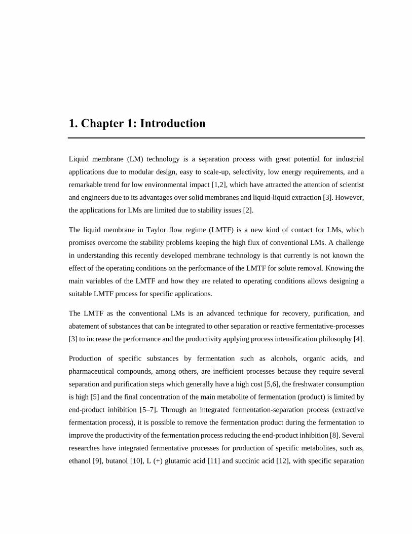
1.1 Liquid membranes and the liquid membrane in Taylor flow
A liquid membrane is a liquid semi-permeable barrier which spatially separates two fluid phases,
donor phase and receiving phase [2,3]. Donor phase (D), contains the solute which will be
transported through the membrane phase (M) to the receiving phase (R) as is shown in Figure 1.
Generally, the membrane phase is composed of organic substances while the donor and receiving
phases are aqueous solutions [19].
The liquid membrane technology is a perstraction process (which involves extraction and back-
extraction processes with membrane separation in a single stage) used for separation or concentration
of substances [2,19]. LM technology has been applied in several fields such as hydrometallurgy,
biotechnology, medical and in general for the treatment of industrial wastewaters [1–3]. LM has
Chapter 1: Introduction 3
been used for removal of toxic metal from effluents, recovery of the metabolites produced on
fermentations, removal of toxic gas agents and, removal of organic or inorganic compounds from
industrial effluents, among others [2,3].
Figure 1. Scheme of the liquid membrane and the involved phases for solute (S) removal.
LM technology, unlike the conventional liquid-liquid extraction, requires a low amount of solvent
due to it is continuously in-situ regenerated, is less energy consuming, the number of stages is
reduced, and is not thermodynamically limited because of the continuous solute removal from the
membrane phase by the receiving phase [2,3,19]. Therefore, LM technology has great potential to
be applied in process intensification [2,20–31]. LMs can reduce the operating costs, environmental
impact, and energy consumption when they are combined with other separation or reactive processes,
such as bioremediation, selective oxidation, fermentation, distillation, absorption, and adsorption [2–
4,26,32–36].
There are three types of liquid membranes: bulk, supported and emulsion liquid membranes. Bulk
liquid membranes have been used to test both mass transport and kinetics at lab-scale due to this LM
is limited by its low specific interface area [3]. Supported liquid membranes (SLM) and emulsion
liquid membranes (ELM) have potential on applications in industrial scale because they provide
large interfacial area among the phases, extraction, and stripping are in one stage, simple operation
and it is possible to process high quantities of compounds (from donor phase) using small volumes
of the membrane phase [2,24]. ELM offers higher mass transport rates than their counterpart SLM
which requires regeneration steps due to membrane liquid phase losses during the process operation
[2]. ELM requires mixing steps for the formation of stable emulsions that later must be disrupted by
thermal breakdown or electrical demulsification and separated in decanters in subsequent steps

4 Applications of a liquid membrane in Taylor flow regime (LMTF) on separation processes and
design of fermentation hybrid systems
[3,19,37]. In order to stabilize the emulsions, usually, it is necessary to add surfactants or surface-
active substances [2,3,19] that also hinders the decantation processes.
In the LM process, there are two main transport mechanisms: passive diffusion (or simple diffusion)
and facilitated transport [25]. Facilitated transport occurs faster than passive diffusion and increases
monotonically as the driving-force, given by the difference of the chemical potential between the
donor and membrane phases, increases [25]. In facilitated transport, an active agent or carrier is
added to the membrane phase [2,25], and it reacts with the solute in the interface D/M in order to
produce a complex. This complex is transported from the interface D/M to the interface M/R, and
here, the complex releases the solute on the receiving phase. The use of a carrier provides selectivity
for a specific solute and high mass transport rate of the solute through the membrane phase [38].
Currently, a new type of contact among the phases of the LM process has been proposed [39] and
developed as perstraction process with the potential to overcome the abovementioned drawbacks of
the LMs. This type of LM keeps a high mass transfer of solute among the phases without using
surfactants and reducing the number of steps of the ELM. This LM uses Taylor flow regime
extending it to three-phases as the way of contact of the phases of the LM (donor, membrane and
receiving phases) and it takes advantage of the enhanced mass transfer of this flow regime [40]. The
mass transfer and the particular hydrodynamics of Taylor flow have been applied in mixing,
separation and reactive processes in order to improve the performance of these processes [41–47].
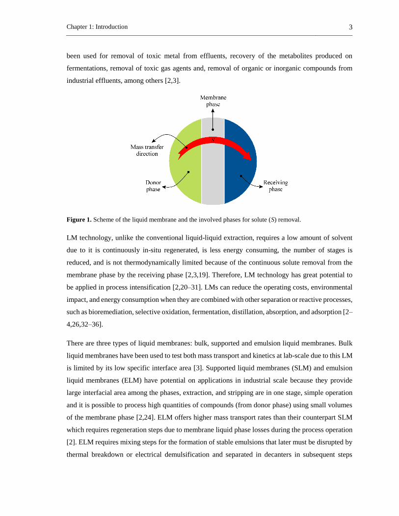
The liquid membrane process was named liquid membrane in Taylor flow regime (LMTF), and as a
proof concept, it was tested for lactic acid removal [39]. While the three phases of the LMTF are
flowing in the same direction within a channel, the transport of the solute through the LMTF (Figure
2) is carried out from the donor phase to the membrane phase and from here to the receiving phase.
The donor and receiving phases are aqueous droplets within the tube (or channel) while the
membrane phase is the continuous phase or liquid slugs in the Taylor flow. Using this configuration,
all phases of the LMTF are in motion and interfaces are continuously renewed.
Figure 2. Solute removal (S) through the liquid membrane in Taylor flow.
Chapter 1: Introduction 5
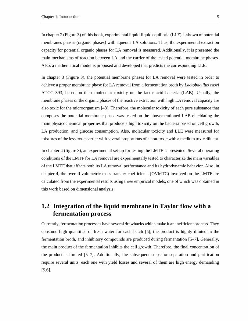
In chapter 2 (Figure 3) of this book, experimental liquid-liquid equilibria (LLE) is shown of potential
membranes phases (organic phases) with aqueous LA solutions. Thus, the experimental extraction
capacity for potential organic phases for LA removal is measured. Additionally, it is presented the
main mechanisms of reaction between LA and the carrier of the tested potential membrane phases.
Also, a mathematical model is proposed and developed that predicts the corresponding LLE.
In chapter 3 (Figure 3), the potential membrane phases for LA removal were tested in order to
achieve a proper membrane phase for LA removal from a fermentation broth by Lactobacillus casei
ATCC 393, based on their molecular toxicity on the lactic acid bacteria (LAB). Usually, the
membrane phases or the organic phases of the reactive extraction with high LA removal capacity are
also toxic for the microorganism [48]. Therefore, the molecular toxicity of each pure substance that
composes the potential membrane phase was tested on the abovementioned LAB elucidating the
main physicochemical properties that produce a high toxicity on the bacteria based on cell growth,
LA production, and glucose consumption. Also, molecular toxicity and LLE were measured for
mixtures of the less toxic carrier with several proportions of a non-toxic with a medium toxic diluent.
In chapter 4 (figure 3), an experimental set-up for testing the LMTF is presented. Several operating
conditions of the LMTF for LA removal are experimentally tested to characterize the main variables
of the LMTF that affects both its LA removal performance and its hydrodynamic behavior. Also, in
chapter 4, the overall volumetric mass transfer coefficients (OVMTC) involved on the LMTF are
calculated from the experimental results using three empirical models, one of which was obtained in
this work based on dimensional analysis.
1.2 Integration of the liquid membrane in Taylor flow with a
fermentation process
Currently, fermentation processes have several drawbacks which make it an inefficient process. They
consume high quantities of fresh water for each batch [5], the product is highly diluted in the
fermentation broth, and inhibitory compounds are produced during fermentation [5–7]. Generally,
the main product of the fermentation inhibits the cell growth. Therefore, the final concentration of
the product is limited [5–7]. Additionally, the subsequent steps for separation and purification
require several units, each one with yield losses and several of them are high energy demanding
[5,6].

6 Applications of a liquid membrane in Taylor flow regime (LMTF) on separation processes and
design of fermentation hybrid systems
Several technologies to improve the fermentation processes have been proposed such as feed-batch
reactor operation, multi-phase reactor operation and bio-catalysis. Bio-catalysis has been the most
used. However, it presents losses of cell viability and enzyme activity [5]. In-situ product removal
(ISPR) has great potential to overcome the drawbacks mentioned above for fermentation processes.
ISPR involves product removal during the fermentative process and can be applied internally or
externally to the fermenter. ISPR has been applied to fuel, chemical, pharmaceutical, and food
products [5]. From the point of view of the microorganisms, ISPR operation can be carried out with
direct or indirect contact in an external or internal unit [5].
These hybrid processes or units are focused on increasing the fermentation product concentration,
removing the inhibitor compounds and reducing the number of steps in the global process allowing
continuous operation. In a hybrid fermentation-separation system, the product removal and the
reaction step are possible to carry out in a recycle loop. Moreover, the product recovery can be
achieved in the same vessel and, sometimes, byproducts may need to be isolated [5].
Several separation processes have been used to achieve a hybrid process where the product is
continuously removed from fermentation. Liquid-liquid extraction, adsorption, and membrane
technologies are the most used in the development of hybrid processes [6,49–52]. The use of one or
another separation technology is highly related to the substance of interest to remove from the
fermentation broth.
Filtration process (micro-filtration) was used to remove cells and to recover the fermentation
product. It was used in the lactic acid fermentation where both fouling and substrate loss were
observed. Thus, it was necessary the treatment of the membranes [51].
The adsorption process requires the use of ion exchange resins and usually two-bed columns. While
one column is removing the product, the second one is in the regeneration step. This technology has
been used for carboxylic acid removal. It provides high product concentration, avoids the use of pH
control and reduces inhibition by a fermentation product [53].
Electrodialysis is a membrane technology that requires to form a carboxylate from the fermentation
broth and electro-conversion of carboxylate into carboxylic acid. Lactic acid fermentation has been
one of the most studied processes using this technology [51,54]. The pH must remain slightly higher
but close to a value of 6. It is known, that the lactic acid in an undissociated form reduces the
microbial activity and at low pH (pH<5) the formation of the undissociated form of lactic acid is

Chapter 1: Introduction 7
promoted [51]. This hybrid process, as adsorptive fermentation, provides pH control on the lactic
acid production reducing product inhibition and providing higher fermentation yields than
conventional batch fermentations [7,54]. An intensified electrodialysis process, LA recovery in
electro-enhanced dialysis (REED) were developed and tested as a promising alternative to be
integrated into a fermentation process [55].
Liquid-liquid extraction integrated to fermentation has been widely studied and usually, it is called
hybrid liquid-liquid extraction-fermentation [6] or extractive fermentation [6,56]. In this process, the
extraction solvent must be highly efficient and, in general, must accomplish the following conditions
[6,50]:
a) Low or non-toxic on the microorganism of the fermentation.
b) Show a high distribution coefficient.
c) High selectivity for the solute.
d) Low solubility in the aqueous phase.
e) High-density difference with the fermentation broth to ensure two-phase separation.
f) Low viscosity and high interfacial tension with low trend to emulsify in the fermentation
broth.
g) High stability.
h) Low cost.
Removal of organic acids from the fermentation broth by reactive liquid extraction has been the main
application for this separation process [18,57–59], where LA removal has been studied [60–63]. The
solvent recovery step or co-extraction step increases the costs due to the use of a co-solvent. Due to
this and the toxicity effects of some solvents, a modified liquid extraction using indirect contact has
been used. It was achieved using a porous non-wetted membrane between the two phases. This
process is called for some authors as perstraction [8,9]. The membrane is used as a contactor to
provide a high interfacial area between the phases and to reduce the toxicity of the solvent on the
microorganism.
LMs are another membrane technology with the potential to be integrated into a fermentative
process. There are several studies on the integration of LMs in fermentative processes, especially for
organic acid removal [48,64–68]. For LA removal both SLM and ELM have been used and tested,
where the recent trend is on the use of ionic liquids within the membrane phase [29,69–77]. Also,
some studies of LM on in-situ LA removal have been published, showing it as promising methods
for efficient LA production [48,58].

8 Applications of a liquid membrane in Taylor flow regime (LMTF) on separation processes and
design of fermentation hybrid systems
In this thesis, the LMTF is tested for in-situ LA removal during LA fermentation by Lactobacillus
casei ATCC 393. In chapter 5 (Figure 3), the experimental set-up of the LMTF is integrated to a
batch LA fermentation of 50 mL (hybrid system), and the effects of the LA removal during
fermentation through the LMTF on cell growth, LA production, and glucose consumption are
evaluated. As compared to a conventional batch LA fermentation, the experimental results show
that it is possible to increase productivity, biomass concentration and LA produced using this LMTF
hybrid system. Additionally, a model for the hybrid system is developed from the experimental
results taking into account LA kinetics and OVMTC of the LMTF. The effect of LMTF system with
several channels on the LA fermentation is simulated, assessing parameters such as, productivity,
final biomass concentration within the fermenter, total LA mass achieved, and the pH within the
fermenter. The results show that the LMTF is also an alternative for pH control of LA fermentative
processes.
Figure 3. Schematic overview of the chapters through this book.
Chapters 2 – 4 of this book are the product of the design of a hybrid system where the LMTF is
integrated to a fermentative process for in situ product removal (chapter 5). Each chapter of this book
is an important stage that has to be carried out to successfully achieve the integration of the LMTF
to a fermentative process. Hence, chapters 2 – 4 are related in between and conducts to chapter 5
Chapter 1: Introduction 9
(Figure 3). To achieve this aim, the LA fermentation was used as a case study. Every section of each
chapter in this book is self-contain and can be read it independently. Most of the sections are already
published or submitted for publication.
1.3 References
[1] M. Aguilar, J.L. Cortina, Solvent Extraction and Liquid Membranes Fundamentals and
Applications in New Materials, 1st ed., Taylor & Francis Group, London, 2008.
[2] V.S. Kislik, Liquid Membranes Principles & Applications in Chemical Separation &
Wastewater Treatment, 1st ed., Elsevier B.V., Amsterdan, 2010.
[3] R.D. Noble, S.A. Stern, Membrane Separations Technology: Principles and Applications, 3rd
ed., Elsevier, Amsterdan, 2003.
[4] J.A. Moulijn, A. Stankiewicz, J. Grievink, A. Górak, Process intensification and process
systems engineering: A friendly symbiosis, Comput. Chem. Eng. 32 (2008) 3–11.
[5] J.M. Woodley, M. Bisschops, A.J.J. Straathof, M. Ottens, Future directions for in-situ product
removal (ISPR), J. Chem. Technol. Biotechnol. 83 (2008) 121–123. doi:10.1002/jctb.1790.
[6] H.-J. Huang, S. Ramaswamy, U.W. Tschirner, B.V. Ramarao, A review of separation
technologies in current and future biorefineries, Sep. Purif. Technol. 62 (2008) 1–21.
[7] C.S. López-Garzón, A.J.J. Straathof, Recovery of carboxylic acids produced by fermentation,
Biotechnol. Adv. 32 (2014) 873–904. doi:10.1016/j.biotechadv.2014.04.002.
[8] S.T. Yang, C. Lu, Extraction-Fermentation Hybrid (Extractive Fermentation), in: Sep. Purif.
Technol. Biorefineries, 1st ed., John Wiley & Sons, 2013: pp. 409–437.
[9] L.M. Vane, Separation technologies for the recovery and dehydration of alcohols from
fermentation broths, Biofuels, Bioprod. Biorefining. 2 (2008) 553–588.
[10] P. Yao, Z. Xiao, C. Chen, W. Li, Q. Deng, Cell growth behaviors of Clostridium
acetobutylicum in a pervaporation membrane bioreactor for butanol fermentation,
Biotechnol. Appl. Biochem. 63 (2016) 101–105. doi:10.1002/bab.1318.
[11] P. Pal, R. Kumar, D. VikramaChakravarthi, S. Chakrabortty, Modeling and simulation of
continuous production of L (+) glutamic acid in a membrane-integrated bioreactor, Biochem.

10 Applications of a liquid membrane in Taylor flow regime (LMTF) on separation processes and
design of fermentation hybrid systems
Eng. J. 106 (2016) 68–86. doi:10.1016/j.bej.2015.11.008.
[12] P.A. Sosa, C. Roca, S. Velizarov, Membrane assisted recovery and purification of bio-based
succinic acid for improved process sustainability, J. Memb. Sci. 501 (2016) 236–247.
doi:10.1016/j.memsci.2015.12.018.
[13] C. Miller, A. Fosmer, B. Rush, T. McMullin, D. Beacom, P. Suominen, Industrial Production
of Lactic Acid, in: Ref. Modul. Life Sci., Elsevier, 2017: pp. 179–188. doi:10.1016/B978-0-
12-809633-8.09142-1.
[14] J. Vijayakumar, R. Aravindand, T. Viruthagiri, Recent Trends in the Production, Purification
and Application of Lactic Acid, Chem. Biochem. Eng. Q. 22 (2008) 245–264.
https://hrcak.srce.hr/24811.
[15] A. Komesu, M.R. Wolf Maciel, R. Maciel Filho, Separation and Purification Technologies
for Lactic Acid – A Brief Review, BioResources. 12 (2017) 6885–6901.
doi:10.15376/biores.12.3.6885-6901.
[16] M. Singhvi, T. Zendo, K. Sonomoto, Free lactic acid production under acidic conditions by
lactic acid bacteria strains: challenges and future prospects, Appl. Microbiol. Biotechnol. 102
(2018) 5911–5924. doi:10.1007/s00253-018-9092-4.
[17] K.L. Wasewar, A.A. Yawalkar, J.A. Moulijn, V.G. Pangarkar, Fermentation of Glucose to
Lactic Acid Coupled with Reactive Extraction: A Review, Ind. Eng. Chem. Res. 43 (2004)
5969–5982. doi:10.1021/ie049963n.
[18] N. Tik, E. Bayraktar, Ül. Mehmetoglu, In situ reactive extraction of lactic acid from
fermentation media, J. Chem. Technol. Biotechnol. 76 (2001) 764–768.
[19] E. V. Yurtov, M.Y. Koroleva, Liquid membranes for extraction, Pet. Chem. 54 (2014) 581–
594. doi:10.1134/S0965544114080192.
[20] A. M. Sastre, A.. Kumar, S. J. P., S. R. K., Improved techniques in liquid membrane
separations: An overview, Sep. Purif. Methods. 27 (1998) 213–298.
[21] B. Sasikumar, G. Arthanareeswaran, A.F. Ismail, Recent progress in ionic liquid membranes
for gas separation, J. Mol. Liq. 266 (2018) 330–341. doi:10.1016/j.molliq.2018.06.081.

Chapter 1: Introduction 11
[22] C.S. Gholap, S. Panja, P. s. Dhami, J. s. Yadav, S.K. Ghosh, Supported Liquid Membrane
transport studies of Pu(IV) using OTDA, a novel diamide, J. Environ. Chem. Eng. 7 (2019)
102784. doi:S2213343718307085.
[23] H. Dou, B. Jiang, M. Xu, J. Zhou, Y. Sun, L. Zhang, Supported ionic liquid membranes with
high carrier efficiency via strong hydrogen-bond basicity for the sustainable and effective
olefin/paraffin separation, Chem. Eng. Sci. 193 (2019) 27–37.
doi:10.1016/j.ces.2018.08.060.
[24] N.M. Kocherginsky, Q. Yang, L. Seelam, Recent advances in supported liquid membrane
technology, Sep. Purif. Technol. 53 (2007) 171–177.
[25] R.W. Baker, Membrane Technology and Applications, 2nd ed., John Wiley & Sons, Ltd,
Chichester, UK, 2004.
[26] G. Breembroek, G. Witkamp, G. Van Rosmalen, Design and testing of an emulsion liquid
membrane pilot plant, Sep. Sci. Technol. 10 (2000) 1539–1571.
[27] P. Cserjési, N. Nemestóthy, K. Bélafi-Bakó, Gas separation properties of supported liquid
membranes prepared with unconventional ionic liquids, J. Memb. Sci. 349 (2010) 6–11.
doi:10.1016/j.memsci.2009.10.044.
[28] L.J. Lozano, C. Godínez, A. P. de los Ríos, F.J. Hernández-Fernández, S. Sánchez-Segado,
F.J. Alguacil, Recent advances in supported ionic liquid membrane technology, J. Memb.
Sci. 376 (2011) 1–14. doi:10.1016/j.memsci.2011.03.036.
[29] J. Marták, Š. Schlosser, S. Vlčková, Pertraction of lactic acid through supported liquid
membranes containing phosphonium ionic liquid, J. Memb. Sci. 318 (2008) 298–310.
doi:10.1016/j.memsci.2008.02.064.
[30] M.F. San Roman, E. Bringas, R. Ibañez, I. Ortiz, Liquid membrane technology: fundamentals
and review of its applications, J. Chem. Technol. Biotechnol. 85 (2010) 2–10.
[31] S. Bazhenov, A. Malakhov, D. Bakhtin, V. Khotimskiy, G. Bondarenko, V. Volkov, M.
Ramdin, T.J.H. Vlugt, A. Volkov, CO2 stripping from ionic liquid at elevated pressures in
gas-liquid membrane contactor, Int. J. Greenh. Gas Control. 71 (2018) 293–302.
doi:10.1016/j.ijggc.2018.03.001.
12 Applications of a liquid membrane in Taylor flow regime (LMTF) on separation processes and
design of fermentation hybrid systems
[32] T. Sirman, L. Pyle, A.S. Grandison, Extraction of organic acids using a supported liquid
membrane., Biochem. Soc. Trans. 19 (1991) 274S.
[33] B. Yordanov, L. Boyadzhiev, Pertraction of citric acid by means of emulsion liquid
membranes, J. Memb. Sci. 238 (2004) 191–197.
[34] D. Cascaval, A. Galaction, C. Oniscu, Selective Pertraction of Carboxylic Acids Obtained by
Citric Fermentation, Sep. Sci. Technol. 39 (2005) 1907–1925.
[35] R. Juang, R. Huang, Separation of citric and lactic acids in aqueous solutions by solvent
extraction and liquid membrane processes, J. Memb. Sci. 136 (1997) 89–99.
[36] M.A. Malik, M.A. Hashim, F. Nabi, Extraction of Metal Ions by ELM Separation
Technology, J. Dispers. Sci. Technol. 33 (2012) 346–356.
[37] F. Leal-Calderon, V. Schmitt, J. Bibette, Emulsion science: basic principles, Second Edi,
Springer, 2007.
[38] H.C. Ferraz, L.T. Duarte, M. Di Luccio, T.L.M. Alves, A.C. Habert, C.P. Borges, Recent
achievements in facilited transport membrane for separation processes, Brazilian J. Chem.
Eng. 24 (2007) 101–118.
[39] J. Fontalvo, A.D. Pérez, Membrana Líquida y proceso para realizarlo, Rad. 15-131023, n.d.
[40] Y. Okubo, T. Maki, N. Aoki, T. Hong Khoo, Y. Ohmukai, K. Mae, Liquid-liquid extraction
for efficient synthesis and separation by utilizing micro spaces, Chem. Eng. Sci. 63 (2008)
4070–4077. doi:10.1016/j.ces.2008.05.017.
[41] R. Gupta, S.S.Y. Leung, R. Manica, D.F. Fletcher, B.S. Haynes, Hydrodynamics of liquid–
liquid Taylor flow in microchannels, Chem. Eng. Sci. 92 (2013) 180–189.
[42] M.T. Kreutzer, F. Kapteijn, J.A. Moulijn, C.R. Kleijn, J.J. Heiszwolf, Inertial and interfacial
effects on pressure drop of Taylor flow in capillaries, AIChE J. 51 (2005) 2428–2440.
[43] B. Zheng, J.D. Tice, R.F. Ismagilov, Formation of droplets of alternating composition in
microfluidic channels and applications to indexing of concentrations in droplet-based assays,
Anal. Chem. 76 (2004) 4977–4982. doi:10.1021/ac0495743.
[44] M.N. Kashid, I. Gerlach, S. Goetz, J. Franzke, J.F. Acker, F. Platte, D.W. Agar, S. Turek,
Chapter 1: Introduction 13
Internal circulation within the liquid slugs of a liquid-liquid slug-flow capillary microreactor,
Ind. Eng. Chem. Res. 44 (2005) 5003–5010. doi:10.1021/ie0490536.
[45] M. Kashid, O. Detraz, M.S. Moya, I. Yuranov, P. Prechtl, J. Membrez, A. Renken, L. Kiwi-
Minsker, Micro-batch reactor for catching intermediates and monitoring kinetics of rapid and
exothermic homogeneous reactions, Chem. Eng. J. 214 (2013) 149–156.
doi:10.1016/j.cej.2012.10.019.
[46] W. Tanthapanichakoon, N. Aoki, K. Matsuyama, K. Mae, Design of mixing in microfluidic
liquid slugs based on a new dimensionless number for precise reaction and mixing operations,
Chem. Eng. Sci. 61 (2006) 4220–4232. doi:10.1016/j.ces.2006.01.047.
[47] M. Mendorf, D.W. Agar, Scale-up of Capillary Extraction Equipment, Chemie Ing. Tech. 83
(2011) 1120–1124.
[48] R. Chen, Y.Y. Lee, Membrane-mediated extractive fermentation for lactic acid production
from cellulosic biomass, Appl. Biochem. Biotechnol. 63–65 (1997) 435–448.
doi:10.1007/BF02920444.
[49] S.A. Ahmad, S.R. Lone, Hybrid Process ( Pervaporation-Distillation ): A Review, Int. J. Sci.
Eng. Res. 3 (2012) 1–5.
[50] K. Kraemer, A. Harwardt, R. Bronneberg, W. Marquardt, Separation of butanol from
acetone–butanol–ethanol fermentation by a hybrid extraction–distillation process, Comput.
Chem. Eng. 35 (2011) 949–963.
[51] P. Pal, J. Sikder, S. Roy, L. Giorno, Process intensification in lactic acid production: A review
of membrane based processes, Chem. Eng. Process. Process Intensif. 48 (2009) 1549–1559.
[52] L.M. Vane, A review of pervaporation for product recovery from biomass fermentation
processes, J. Chem. Technol. Biotechnol. 80 (2005) 603–629.
[53] K. Hetényi, Á. Németh, B. Sevella, Role of pH-regulation in lactic acid fermentation: Second
steps in a process improvement, Chem. Eng. Process. Process Intensif. 50 (2011) 293–299.
doi:10.1016/j.cep.2011.01.008.
[54] X. Wang, Y. Wang, X. Zhang, H. Feng, T. Xu, In-situ combination of fermentation and
electrodialysis with bipolar membranes for the production of lactic acid: continuous

14 Applications of a liquid membrane in Taylor flow regime (LMTF) on separation processes and
design of fermentation hybrid systems
operation., Bioresour. Technol. 147 (2013) 442–8.
[55] O.A. Prado Rubio, S.B. Jørgensen, G.E. Jonsson, Lactic Acid Recovery in Electro-Enhanced
Dialysis: Modelling and Validation, Comput. Aided Chem. Eng. 26 (2009) 773–778.
doi:10.1016/S1570-7946(09)70129-4.
[56] H. Honda, Y. Toyama, H. Takahashi, Effective lactic acid production by two-stage extractive
fermentation, J. Ferment. Bioeng. 79 (1995) 589–593.
[57] M. Matsumoto, In situ Extractive Fermentation of Lactic Acid by Rhizopus oryzae in an Air-
lift Bioreactor, Chem. Biochem. Eng. Q. 32 (2018) 275–280.
doi:10.15255/CABEQ.2017.1208.
[58] M. Boonmee, O. Cotano, S. Amnuaypanich, N. Grisadanurak, Improved Lactic Acid
Production by In Situ Removal of Lactic Acid During Fermentation and a Proposed Scheme
for Its Recovery, Arab. J. Sci. Eng. 41 (2016) 2067–2075. doi:10.1007/s13369-015-1824-5.
[59] Y.K. Hong, W.H. Hong, D.H. Han, Application of reactive extraction to recovery of
carboxylic acids, Biotechnol. Bioprocess Eng. 6 (2001) 386–394. doi:10.1007/BF02932319.
[60] Susanti, J.G.M. Winkelman, B. Schuur, H.J. Heeres, J. Yue, Lactic Acid Extraction and Mass
Transfer Characteristics in Slug Flow Capillary Microreactors, Ind. Eng. Chem. Res. 55
(2016) 4691–4702.
[61] V.S. Kislik, Solvent Extraction: Classical and Novel Approaches, 1st ed., Amsterdam, 2012.
[62] A. Labbaci, G. Kyuchoukov, J. Albet, J. Molinier, Detailed investigation of lactic acid
extraction with tributylphosphate dissolved in dodecane, J. Chem. Eng. Data. 55 (2010) 228–
233. doi:10.1021/je900315r.
[63] A. Krzyzaniak, B. Schuur, A.B. De Haan, Equilibrium studies on lactic acid extraction with
N,N-didodecylpyridin-4-amine (DDAP) extractant, Chem. Eng. Sci. 109 (2014) 236–243.
[64] S.C. Lee, Extraction of succinic acid from simulated media by emulsion liquid membranes,
J. Memb. Sci. 381 (2011) 237–243. doi:10.1016/j.memsci.2011.07.039.
[65] Q.-Z. Li, X.-L. Jiang, X.-J. Feng, J.-M. Wang, C. Sun, H.-B. Zhang, M. Xian, H.-Z. Liu,
Recovery Processes of Organic Acids from Fermentation Broths in the Biomass-Based
Chapter 1: Introduction 15
Industry, J. Microbiol. Biotechnol. 26 (2016) 1–8. doi:10.4014/jmb.1505.05049.
[66] N. Jusoh, N. Othman, N.A. Nasruddin, Emulsion liquid membrane technology in organic acid
purification, Malaysian J. Anal. Sci. 20 (2016) 436–443. doi:10.17576/mjas-2016-2002-28.
[67] N. Harruddin, S.M. Saufi, C.K.M. Faizal, A.W. Mohammad, Removal of acetic acid from
aqueous solution by polyethersulfone supported liquid membrane, Chem. Eng. Trans. 56
(2017) 847–852. doi:10.3303/CET1756142.
[68] F. Garavand, S.H. Razavi, I. Cacciotti, Synchronized extraction and purification of L-lactic
acid from fermentation broth by emulsion liquid membrane technique, J. Dispers. Sci.
Technol. 39 (2018) 1291–1299. doi:10.1080/01932691.2017.1396225.
[69] S. Joachim, P. Wasserscheid, Production of lactic acid by way of fermentation and extraction
of amines, US 2010/0273224 A1, 2010. http://www.google.st/patents/US20100273224
(accessed March 23, 2014).
[70] C. Schöller, J. Chaudhuri, D. Phyle, Emulsion liquid membrane extraction of organic acids—
I. A theoretical model for lactic acid extraction with emulsion swelling, Chem. Eng. Sci. 47
(1992) 41–48. http://www.sciencedirect.com/science/article/pii/000925099280198L
(accessed April 24, 2014).
[71] R.-S. Juang, S.-H. Lee, R.-C. Shiau, Mass-transfer modeling of permeation of lactic acid
across amine-mediated supported liquid membranes, J. Memb. Sci. 137 (1997) 231–239.
doi:10.1016/S0376-7388(97)00206-8.
[72] M. Matsumoto, T. Takagi, K. Kondo, Separation of lactic acid using polymeric membrane
containing a mobile carrier, J. Ferment. Bioeng. 85 (1998) 483–487.
[73] A. Demirci, A.L. Pometto, K.R. Harkins, Rapid screening of solvents and carrier compounds
for lactic acid recovery by emulsion liquid extraction and toxicity on Lactobacillus casei
(ATCC 11443), Bioseparation. 7 (1999) 297–308.
[74] B.S. Chanukya, M. Kumar, N.K. Rastogi, Optimization of lactic acid pertraction using liquid
emulsion membranes by response surface methodology, Sep. Purif. Technol. 111 (2013) 1–
8.
[75] N. Rastogi, B.S. Chanukya, Supported Liquid Membrane Composed of Tertiary or/and
16 Applications of a liquid membrane in Taylor flow regime (LMTF) on separation processes and
design of fermentation hybrid systems
Quaternary Amine for the Extraction of Lactic Acid, Int. J. Membr. Sci. Technol. 2 (2015)
19–28. doi:10.15379/2410-1869.2015.02.02.03.
[76] A. Kumar, A. Thakur, P.S. Panesar, Statistical optimization of lactic acid extraction using
Green Emulsion Ionic Liquid Membrane (GEILM), J. Environ. Chem. Eng. 6 (2018) 1855–
1864. doi:10.1016/j.jece.2018.01.037.
[77] A. Kumar, A. Thakur, P.S. Panesar, Lactic acid extraction using environmentally benign
Green emulsion ionic liquid membrane, J. Clean. Prod. 181 (2018) 574–583.
doi:10.1016/j.jclepro.2018.01.263.
Chapter 2: Liquid-liquid equilibria of potential liquid membranes for lactic acid removal 17
2. Chapter 2: Liquid-liquid equilibria of potential liquid
membranes for lactic acid removal

18 Applications of a liquid membrane in Taylor flow regime (LMTF) on separation processes and
design of fermentation hybrid systems
2.1 Liquid-liquid equilibria for trioctylamine/1-
dodecanol/lactic acid/water system at 306.1, 310.1 and 316.1
k: experimental data and prediction1
Abstract
Liquid-liquid equilibria of aqueous solutions of lactic acid with trioctylamine diluted in 1-dodecanol
was measured experimentally at three temperatures (306.1, 310.1 and 316.1 ±0.1 K). During the
transfer process, lactic acid reacts with trioctylamine to produce an amine-lactate complex. Two
models were proposed to predict the liquid-liquid equilibria. The first model considered the ratio of
chemical equilibrium concentration and the distribution coefficient. Those parameters have been
determined by fitting the experimental data. It was found that as temperature increases, the
distribution coefficient increases and equilibrium constant decreases. The second proposed model
involved the Non-Random two liquid activity model. Energies of binary interaction and equilibrium
constant were fitted to experimental data. The equilibrium constant and partition coefficients show
the same trends that the first model, however the first model shows a better prediction as compared
to the second model of the liquid-liquid equilibrium data. These two models are especially suitable
at low lactic acid concentrations in the aqueous phase where the experimental standard deviation is
low.
1 This section has been published in: J. Chem. Eng. Data 2016, 61, 2269−2276: Alan D. Perez, Sneyder
Rodríguez-Barona, Javier Fontalvo

Chapter 2: Liquid-liquid equilibria of potential liquid membranes for lactic acid removal 19
2.1.1 Introduction
Lactic acid (LA) is an important product due to its applications in food (as food additive and
preservative), and in chemical, cosmetic and pharmaceutical industries. Nowadays interest in LA
production and recovery, for instance from fermentation broths, is growing due to the potential
production of biodegradable and biocompatible polymers, mainly polylactic acid [1–3].
On the other hand, reactive equilibria systems have attracted significant attention, specifically in
extraction of carboxylic acids. LA recovery has been studied using different technologies including
liquid extraction [1,4–6] and liquid membranes [7–9]. In these separation process, tertiary amines as
trialkylamine (TAA), trioctylamine (TOA), alamine 336 have been often used for removal of LA
and other organic acids [1,4,17,5,10–16]. Alamine has been used as extractant with different
solvents as 1-dodecanol, 1-decanol, 1-hexanol, phenylethanol and cyclohexanol to remove pyruvic
acid [11,15]. TAA in a mix of 1-octanol/n-heptane was studied to extract lactic, malic and citric
acids [5]. TOA has been tested in mixtures of decanol, dodecane, 1-octanol for removal of LA from
aqueous solutions [1,5,13,18].
Several liquid-liquid equilibria (LLE) models for systems containing carboxylic acids and tertiary
amines have been proposed. A method based on chemical modeling that involved a thermodynamic
extraction constant [5], mass balances and a dissociation constant was suggested to predict LLE of
lactic, malic and citric acids in amine solutions [5]. In other studies, mass action law of equilibria,
apparent equilibrium constant and the amine concentration were used to predict LLE of carboxylic
acids such as lactic, acetic, propionic and butyric [6,10,12]. A similar study, that included mass
action law, the distribution coefficient and Henderson-Hasselbalch equation were used to model the
LLE for pyruvic acid with TOA in 1-octanol system [15]. SERLAS model based on solvation energy
relationship was proposed to predict the LLE for mixtures of water, pyruvic acid, alcohol and
alamine [11]. Juang & Huang [13] proposed a model based on distribution ratios and equilibrium
constants, and the LA dissociation constant in water to predict equilibria data of reactive extraction
of LA with an amine extractant. Probably, the most detailed LLE model involved a method of Gibbs
energy minimization using a flash algorithm, developed by Großmann, combined with the modified
Pitzer and Debye-Hückel equations of ionic species [14,16,17]. In this study, an infrared
spectroscopy technique was used to obtain information about the stoichiometry of the complex
formation.
In this work, the experimental values of the reactive liquid-liquid equilibria of TOA/1-
Dodecanol/Water/Lactic acid system are presented at 306.1, 310.1 and 316.1 K. In this system there
20 Applications of a liquid membrane in Taylor flow regime (LMTF) on separation processes and
design of fermentation hybrid systems
is a chemical reaction between lactic acid and TOA to produce an amine-lactate complex. This
complex promotes the separation and provides a higher separation degree than using only the organic
solvent. Two models were proposed to predict the reactive liquid-liquid equilibria. The first model
considers the distribution coefficient, the equilibrium constant and the material balances. The
prediction of this model gives an appropriate description of the liquid-liquid equilibria experimental
data. The second model involves an activity coefficient model and it results in a more complex to fit
set of equations, due to the amount of parameters to estimate and the nonlinearity of the model.
2.1.2 Experimental section
Materials
Trioctylamine and 1-dodecanol for synthesis were supplied by Merck Millipore. Both reagents are
colorless and practically water insoluble (0.0001 and 0.004 g·L-1 at 298.15 K respectively). L(+)-
lactic acid were supplied by Panreac Química S.A.U. (assay 88.0-92.0%). The purity of lactic acid
was assessed by titration with NaOH of Carlo Herba (assay ≥ 97.0%) using Metrohm automatic
titrator (702 SM Titrino, 703 TI Stand). Aqueous solutions of lactic acid (150 g·L-1) were heated at
363.1 K under total reflux for 12 hours for dimmers hydrolysis [1,3]. Water HPLC grade was used
for all aqueous solutions.
Experimental Procedure and Analysis
Experimental LLE was carried out at three temperatures (306.1, 310.1 and 316.1 K) with 16 samples
for each temperature. The two proposed models in this paper contain 2 and 15 parameters,
respectively. Thus, 16 experimental points were used to fit the corresponding parameters in these
models. All liquid−liquid equilibrium experiments were carried out in 1.5 ml vials. At the beginning
of each experiment, every vial contained 0.4 ml of organic phase (0.8 mol·L-1 of TOA in 1-
dodecanol) and 0.4 ml of aqueous phase (with LA concentrations between 10 and 150 g·L-1). The
LA concentrations in the aqueous phase were selected based on the final concentration of LA in
fermentation broths [2,19–21]. The TOA concentration in the organic phase was selected based on
the studies of Juang [8] for LA removal with a supported liquid membrane using TOA. And 1-
dodecanol was selected due to its lower water solubility than that of alcohols and alkanes of smaller
carbon chain. The experimental protocol was performed at constant temperature and consisted of
three steps: agitation, decantation and sampling. Firstly, each vial was shaken during 72 hours at 180
rpm in a shaking water bath (Boekel Scientific) with a reciprocating shaking (±0.1 °C). Then, the
samples were decanted (stabilization step) for 72 hours in a GC oven (ChromPack with ±0.1 °C).

Chapter 2: Liquid-liquid equilibria of potential liquid membranes for lactic acid removal 21
Afterwards, the LA residual concentration in the aqueous phase was measured by HPLC (Elite
LaChrom), using ORH-801 column (Transgenomic®) and RI detector at 308 K. As a mobile phase,
0.01 N H2SO4 solution was used at 0.8 ml·min-1 flow rate. By using the mass balances the
corresponding total LA concentrations in the organic phase were calculated. The volume of the
organic and aqueous phases were assumed constant that according to our calculations introduce a
maximal error of ±0.9%. However, Sabalová et al. [22] have calculated a maximal error of ±3% for
butyric acid using several solvents with TOA.
Distribution coefficient was measured at the highest LA concentration in the aqueous phase at the
three temperatures following the aforementioned procedure. For the organic phase 1-dodecanol was
used. The equilibria concentration of LA in the aqueous phase was measured by HPLC and in the
organic phase by titration using Metrohm automatic titrator (702 SM Titrino, 703 TI Stand).
2.1.3 Theoretical section
The liquid-liquid equilibria system consists of TOA and 1-dodecanol in the organic phase, and lactic
acid in the aqueous phase. The mass transfer of organic compounds toward the aqueous phase was
neglected due to the low solubility of TOA and 1-dodecanol in water (Merck material safety data
sheets - MSDS). It was observed that for alcohols increasing the carbon chain length, water solubility
decreases being 1-dodecanol one of the alcohols with a high hydrophobicity [11]. The water
solubility, with and without LA in 1-dodecanol and TOA/1-dodecanol, were measured in this paper
using Karl-Fischer titration to obtain values of 3.96% ±0.05, 3.03% ±0.05, 4.98% ±0.22 and 1.75%
±0.20 w/w, respectively at 310.5 K. Consequently, in this work the water mass transfer between the
phases is not taken into account in the reported data and also LA is considered as the only compound
that is transferred between the liquid phases.
The LA in the organic phase comes from two contributions: free LA that is soluble in the organic
phase and LA that reacts with TOA at the interface and in the bulk of the organic phase to produce
an amine-lactate complex according to equation 1. Most of the lactic acid in the organic phase is
mainly due to chemical reaction because the solubility of LA in 1-dodecanol is low. Nevertheless,
both contributions are included in the models that are presented below.
TOALALATOA (1)
Two liquid-liquid equilibria models were proposed. The first model uses the material balances, the
distribution coefficient and the reaction equilibrium constant. The reaction equilibrium constant is

22 Applications of a liquid membrane in Taylor flow regime (LMTF) on separation processes and
design of fermentation hybrid systems
molar concentration based, and generally it is called concentration chemical equilibrium ratio [23]
or apparent equilibrium constant [6,10,24]. The second model takes into account the activities of the
species involved in the system and the chemical equilibrium constant based on activity coefficients.
Model based on equilibrium constant and distribution coefficient
This liquid-liquid equilibria model involves equation 1 and a value of the reaction stoichiometric
ratio. Some researchers have found stoichiometric ratios (TOA:LA) of (1:1), (1:2), and (2:3) [5,9]
or (1:1), (1:2) and (1:3) [24,25]. Experimentally this ratio was calculated in this paper with the free
LA, LA-TOA complex and total TOA concentrations at equilibrium in the organic phase using the
experimental data where the total LA concentration in the organic phase at each temperature is
maximum. A simple equation of the liquid-liquid equilibria for this system can be developed from
the equilibrium constant (eq. 2) with a stoichiometric ratio of (1:1), a distribution coefficient (eq. 3),
the LA mass balance in the organic phase (eq. 4) taking into account the TOA mass balance (eq. 5),
however, the followed model can be derived to several stoichiometric ratios (1:ϕ). The stoichiometric
ratio was estimated from the experimental data as it is shown below.
orgorg
org
ETOALA
TOALAK
][][
][
(2)
aq
org
DLA
LAK
][
][
(3)
orgorgTotorg TOALALALA ][][][ , (4)
orgTOAorg TOALACTOA ][][ 0
(5)
Combining equations 2-5, the following expression can be obtained:
aqED
DTOAEDaqED
Totorg
LAKK
KCKKLAKKLA
][1
][][
02
.
(6)
KE and KD were calculated at each temperature by minimizing the sum of squares of the deviations
between the experimental and predicted LA concentrations in the organic phase (eq. 7). It was used
fmincon and globalsearch of Matlab® with the interior point algorithm and a routine that find the
optimum value of the error with a global minimum.
2exp
min ][][ org
pred
org LALA
(7)

Chapter 2: Liquid-liquid equilibria of potential liquid membranes for lactic acid removal 23
If the enthalpy and entropy of the complexation reaction are assumed to be constant over the short
temperature range [24,25] as occurs in this work, the Van’t Hoff’s equation can be used as follows,
where the enthalpy and entropy change of reaction can be obtained:
R
S
RT
HK rxn
E
ln
(8)
Model based on NRTL with chemical reaction
This model was developed taking into account the material balance, phase equilibria and the
equilibrium equations for both liquid phases, under the condition that the LA is the only substance
that is transferred from the aqueous phase to the organic phase.
The molar balance includes the chemical reaction (for TOA and LA in the organic phase) and the
LA transferred from the aqueous phase to the organic phase (eq. 9-12).
LA
II
TOALA
II
LA
I
LA zFxLxLxL 221 (9)
OH
I
OH zFxL221
(10)
DC
II
DC zFxL 112 (11)
TOA
II
TOALA
II
TOA zFxLxL 22 (12)
Phase equilibrium is given by equation 13:
II
LA
II
LA
I
LA
I
LA xx
(13)
And the equilibrium equation of the reaction as a function of activities is given by:
II
LA
II
LA
II
TOA
II
TOA
II
TOALA
II
TOALA
eq
xx
xK (14)
The proposed model, using NRTL activity coefficient model (eq. 15), requires fifteen binary
interaction energies that are unknowns (eq. 16 - 17).

24 Applications of a liquid membrane in Taylor flow regime (LMTF) on separation processes and
design of fermentation hybrid systems
N
k
kkj
N
l
ljljl
ij
N
jN
k
kkj
ijj
N
k
kki
N
j
jjiji
i
xG
Gx
xG
Gx
xG
xG
1
1
1
11
1ln
(15)
RTgg iiijji
(16)
jijijijiG exp
(17)
These energy parameters were fitted using the experimental data. Values of the reaction equilibrium
constant at each temperature from the first model were used as initial values in the optimization
process. The αij parameters values were selected in agreement with the categories described by
Prausnitz [26] and are presented in Table 1.
Table 1. Nonrandomness constant for binary ij interactions for the TOA/1-Dodecanol/LA/water system26.
αij LA TOA 1DC LA-TOA H2O
LA 1 0.3 0.4 0.3 0.4
TOA 0.3 1 0.32 0.23 0.37
1DC 0.4 0.32 1 0.39 0.42
LA-TOA 0.3 0.23 0.39 1 0.4
H2O 0.4 0.37 0.42 0.4 1
The gij parameters were fitted at each temperature using a minimization of the following error square
sum, based on LA partition coefficient[14].
N
m
Q
n nm
cal
mmEQS
2
exp
exp
(18)
ac
m
org
mm xx
(19)
To estimate the gij parameters and Keq, the sum square error in the equation 18 was used as
minimization function using fminsearch of Matlab®.

Chapter 2: Liquid-liquid equilibria of potential liquid membranes for lactic acid removal 25
2.1.4 Results and discussion
Experimental LLE Data
The equilibrium experimental data at each temperature are shown in the tables 2-4. In the organic
phase, LA molar fraction corresponds to the total concentration of LA (free and complex form). The
molar fraction deviation was calculated as error propagation [27] taking into account LA initial
concentration deviation (by HPLC) and volumetric measurement error with an automatic pipet.
Figure 1. a) Experimental liquid-liquid equilibria for the TOA/1-Dodecanol/LA/water system at three different
temperatures and b) experimental standard deviation as function of the LA concentration in the aqueous phase.
Figure 1a shows the liquid-liquid equilibria experimental molar fractions of lactic acid at three
temperatures and Figure 1b displays the standard deviation (s2 = 1/n*Σ(xi-x), where n is the data
number, xi are the experimental data and x is the mean of the experimental data) for the three
temperatures, with a maximum deviation of 0.00146. The standard deviations were calculated by
using the experimental data at the three temperatures for each LA concentration in the aqueous phase

26 Applications of a liquid membrane in Taylor flow regime (LMTF) on separation processes and
design of fermentation hybrid systems
in order to compare the experimental results among temperatures as it is shown in Figure 1b. The
largest standard deviation corresponds to the higher LA concentration. The experimental data at
306.1 and 310.1 K have the same trend, except one point at 310.1 K with a LA molar fraction of
0.1550 in the organic phase and the cause of the deviation in this point is unknown for us. The
experimental data at 316.1 K have a clear trend at low LA concentrations, but the data scatter
increases at higher concentrations and its trend is less clear (specially the point at the highest LA
concentration). This may be due to water evaporation that increases as the temperature rises and the
high LA concentrations. The vial is a closed container however vapor losses can happen because the
containers were closed manually.
Table 2. Measured liquid-liquid equilibria molar fractions for the TOA/1-Dodecanol/LA/water system at 306.1
K.
Aqueous
phase Organic phase
xLA xLA x1DC xTOA
Equilibrium data at 306.1 K
0.0003 0.0249 0.7643 0.2107
0.0004 0.0509 0.7440 0.2051
0.0007 0.0733 0.7264 0.2003
0.0012 0.0930 0.7110 0.1960
0.0018 0.1099 0.6978 0.1924
0.0028 0.1229 0.6876 0.1896
0.0038 0.1350 0.6780 0.1869
0.0050 0.1447 0.6704 0.1848
0.0068 0.1489 0.6671 0.1839
0.0084 0.1555 0.6620 0.1825
0.0099 0.1621 0.6568 0.1811
0.0114 0.1692 0.6512 0.1795
0.0129 0.1772 0.6450 0.1778
0.0156 0.1736 0.6478 0.1786
0.0161 0.1795 0.6432 0.1773
0.0174 0.1784 0.6441 0.1776 aStandard uncertainties u(x)=0.00146, u(T)=0.1K.
High LA concentrations in the organic phase, corresponding to LA molar fractions higher than 0.15
at each temperature, were used to calculate the equilibrium constant. In these experimental results,
the molar ratio TOA and total LA in the organic phase (at the maximum value) corresponds to 1.02,
1.06, and 1.23 at 306.1 K, 310.1 K and 316.1 K respectively. These results indicate that for the low

Chapter 2: Liquid-liquid equilibria of potential liquid membranes for lactic acid removal 27
LA concentrations used in our experiments the stoichiometry ratio (TOA:LA) is 1:1. Perhaps, for
higher LA concentrations the TOA:LA ratio could be different.
Table 3. Measured liquid-liquid equilibria molar fractions for the TOA/1-Dodecanol/LA/water system at 310.1
K.
Aqueous
phase Organic phase
xLA xLA x1DC xTOA
Equilibrium data at 310.1 K
0.0005 0.0227 0.7661 0.2112
0.0005 0.0506 0.7442 0.2052
0.0007 0.0736 0.7262 0.2002
0.0015 0.0893 0.7139 0.1968
0.0025 0.1028 0.7033 0.1939
0.0038 0.1117 0.6963 0.1920
0.0045 0.1272 0.6842 0.1886
0.0040 0.1550 0.6624 0.1826
0.0060 0.1565 0.6612 0.1823
0.0074 0.1646 0.6549 0.1805
0.0090 0.1707 0.6501 0.1792
0.0110 0.1733 0.6480 0.1787
0.0126 0.1795 0.6432 0.1773
0.0145 0.1837 0.6399 0.1764
0.0154 0.1861 0.6380 0.1759
0.0164 0.1873 0.6370 0.1756 aStandard uncertainties u(x)= 0.00146, u(T)=0.1K.
Also a small amount of free LA was calculated that corresponds to LA that is soluble in the organic
phase. Several studies have shown that LA solubility in 1-dodecanol is low [11], therefore this
amount of free LA must be low. The maximum calculated free lactic acid concentrations in the
organic phase were calculated using equation 3 and the total amount of LA in the organic phase to
obtain 0.069, 0.155 y 0.260 molL-1 at 306.1 K, 310.1 K and 316.1 K, respectively. The calculated
values of KD are shown below (Table 5).

28 Applications of a liquid membrane in Taylor flow regime (LMTF) on separation processes and
design of fermentation hybrid systems
Table 4. Measured liquid-liquid equilibria molar fractions for the TOA/1-Dodecanol/LA/water system at 316.1
K.
Aqueous
phase Organic phase
xLA xLA x1DC xTOA
Equilibrium data at 316.1 K
0.0006 0.0209 0.7675 0.2116
0.0006 0.0485 0.7458 0.2056
0.0009 0.0715 0.7279 0.2007
0.0012 0.0926 0.7113 0.1961
0.0021 0.1074 0.6997 0.1929
0.0034 0.1161 0.6929 0.1910
0.0034 0.1387 0.6752 0.1861
0.0048 0.1469 0.6687 0.1844
0.0069 0.1482 0.6678 0.1841
0.0075 0.1635 0.6557 0.1808
0.0102 0.1589 0.6593 0.1818
0.0101 0.1817 0.6414 0.1768
0.0125 0.1809 0.6421 0.1770
0.0152 0.1774 0.6448 0.1778
0.0167 0.1744 0.6472 0.1784
0.0200 0.1542 0.6630 0.1828 aStandard uncertainties u(x)= 0.00146, u(T)=0.1K.
Table 5. Distribution coefficients, equilibrium constant and fitting deviation (eq 18) for the TOA/1-
Dodecanol/LA/water system using the model based on the equilibrium constant and distribution coefficient.
Temperature
(K) KD KE
Sum of
square error KD (exp)b
306.1 0.0809 152.8 0.0066 0.0816 ± 0.0003
310.1 0.1920 49.2 0.0407 0.0916 ± 0.0007
316.1 0.2627 34.5 0.0272 0.1060 ± 0.0007 aStandard uncertainties u(T)=0.1K. bExperimental values in 1-dodecanol at 150 g·L-1 of LA in the aqueous
phase.
Data fit model based on the equilibrium constant and distribution coefficient
Figure 2, shows the obtained data fit at the three temperatures. At 316.15 K the values with a high
scatter were not taken into account (0.1589, 0.1809, 0.1774, 0.1744 and 0.1542 LA molar fraction
in the organic phase). Also, Figure 3 shows the fitted values of distribution coefficients and the

Chapter 2: Liquid-liquid equilibria of potential liquid membranes for lactic acid removal 29
equilibrium constant as function of temperature. These values are also included in Table 5 where the
corresponding fitting deviations are shown.
Figure 2. Liquid-liquid equilibria and model fit for the TOA/1-Dodecanol/LA/water system using the model
based on equilibrium constant and distribution coefficient. Symbols represent experimental data and
discontinuous lines the fitted model.
The distribution coefficient increases as temperature rises (Table 5, Figure 3a), due to higher
solubility of LA as expected. The higher the temperature, the higher the fitting deviation will be.
However, the error fit at 316.1 K is below than 310.1 K, due to 316.1K the scatter values were not
considered for fitting. Experimental KD values (Table 5) linearly increase with increasing. A good
agreement between the fitted and the measured values of KD was found at 306.1 K. However,
experimental KD values have a lower dependence of temperature than the fitted values, perhaps
because in the last case there is not TOA in the organic phase. If TOA is present in the organic phase,
a solvation of TOA-LA complex on free LA can improve LA solubility. There is not good agreement
between experimental and predicted ELL data if the experimental values of KD are used in eq 6 (not
shown). In this case, the predicted correlations of LA in the organic phase become less sensitive to
temperature than measured values shown in Figure 1a.
30 Applications of a liquid membrane in Taylor flow regime (LMTF) on separation processes and
design of fermentation hybrid systems
Figure 3. a) Temperature effect on the distribution coefficient. b) Van’t Hoff’s fit to determine the values of
enthalpy change of reaction and entropy (TOA/1-Dodecanol/LA /water system). Data calculated from the
model based on equilibrium constant and distribution coefficient.
The values of heat of reaction and entropy change of reaction were estimated from the slope and
intercept of the straight line in the Figure 3b. The equilibrium constant decreases as temperature
rises, being an exothermic reaction (ΔHrxn = -27.36 kcal·mol-1). The nature of this reaction is due
to the complexation reaction in the organic phase that involves a proton-transfer or hydrogen bond
[25]. The entropy change was estimated as -0.0798 kcal·(mol·K)-1.
In agreement with equation 6 and the results of Figure 2, two limits cases can be analyzed. For low
and high LA concentration in the aqueous phase equations 20-21 can be obtained from equation 6,
respectively.
aqDTOAETotorg LAKCKLA ][1][ 0
,
(20)
ETOAaqDTotorg KCLAKLA 1][][ 0
,
(21)
At low LA concentrations, independently of the temperature, all LA molecules react with TOA
molecules to produce an amine-lactate complex, due to an excess of TOA. These values of LA

Chapter 2: Liquid-liquid equilibria of potential liquid membranes for lactic acid removal 31
concentrations in the organic phase are described by equation 20 as it is shown in Figure 2. The
effect of temperature on the LA concentration in the organic phase at low LA concentrations is not
significant, and it can be observed in Figure 2 with the predicted data (solid discontinuous lines).
Based on equation 20, the LA concentration ratio between the organic and the aqueous phases is
directly proportional to KD and KE. Although, KD increases and KE decreases as the temperature rises
the effect of temperature on KE is more significant and thus the LA concentration in the organic
phase slightly decreases as the temperature rises at low LA concentrations in the aqueous phase.
At high LA concentrations, LA is in excess for a stoichiometric ratio (TOA:LA) of 1:1 and most of
the LA molecules react with TOA. The remaining LA is solubilized as free acid in the organic phase
as it is described by equation 21 (Figure 2). Equation 21 shows that the LA concentration in the
organic phase increases as the LA concentration in the aqueous phase rises for high LA
concentrations in this phase. If, in equation 21, KD is zero (no solubility of LA in the organic phase)
the total LA concentration in the organic phase would be independent of the LA concentration in the
aqueous phase. On the other hand, if KE is zero (without chemical reaction) the total LA
concentration in the organic phase will be proportional to the lactic acid concentration in the aqueous
phase (from eq. 6).
Model based on NRTL with chemical reaction
The calculated LA concentrations in the organic phase using this model are presented in Figure 4
where the fitted Keq values are 25.9049, 19.7178 and 11.9151 at 306.1 K, 310.1 K and 316.1 K
respectively. The calculated equilibrium constants decrease as temperature increases. This trend is
in accordance with results of the first model, however the values differ. The prediction of the model
at low aqueous LA concentration is better than at high LA concentrations because, as it was shown
above, the experimental standard deviation of the LA concentration in the organic phase increases
as the LA concentration rises in the aqueous phase. The binary interaction parameters (gij in the eq.
16) are summarized in Table 6.
Table 6. Energies of interaction between an i-j pair molecules, obtained from data fit for the TOA/1-
Dodecanol/LA/water system using the model based on NRTL with chemical reaction.
gij LA TOA 1DC LA-TOA H2O
LA 1768.12 286.798 85.8743 880 774.239
TOA 286.798 631.92 2568 565.924 657.285
1DC 85.8743 2568 1320.41 538.445 731
LA-TOA 880 565.924 538.445 1686.7 857.265
H2O 774.239 657.285 731 857.265 1064

32 Applications of a liquid membrane in Taylor flow regime (LMTF) on separation processes and
design of fermentation hybrid systems
The gij parameters and Keq were used to calculate the partition coefficient as function of activity as
it is shown in equation 22.
II
LA
I
LA
I
LA
II
LA Kx
x
(22)
Figure 4. Liquid-liquid equilibria and model fit for the TOA/1-Dodecanol/LA/water system using a model
based on NRTL. Symbols represent experimental data and discontinuous lines the fitted model.
The partition coefficient was calculated at each concentration of equilibrium and at three
temperatures. These results (Figure 5) show that the coefficient distribution is approximately
constant at each temperature. However, at low LA concentrations the K values are higher than at
high LA concentrations. In order to compare these results, the ratio between KD and K can be
estimated using equation 23.
org
Tot
aq
TotD
C
CKK
(23)

Chapter 2: Liquid-liquid equilibria of potential liquid membranes for lactic acid removal 33
A single KD value was calculated at each temperature from the first model. Also KD values, calculated
with equation 23, were calculated for the second model (NRTL model) as function of LA
concentration at each temperature. The calculated KD values in the second model were practically
constant, similar to the K values shown in the Figure 5. To compare KD values between the two
models, the mean KD values were used from the second model. According to the values of KD in the
first model, the following K values were obtained: 0.9846, 0.9813 and 0.9858 at 306.1, 310.1 and
316.1 K, respectively. In the first model the partition coefficients are approximately one order of
magnitude higher than those in the second model. Nevertheless, the data fit from the first model was
in a better agreement with experimental data than the second proposed model. These two models are
especially suitable at low lactic acid concentrations in the aqueous phase where the experimental
standard deviation is low.
Figure 5. Partition coefficients as function of LA concentration in the aqueous phase and temperature
calculated by the NRTL model.
2.1.5 Conclusions
Liquid-liquid equilibria for the trioctylamine/1-dodecanol/lactic acid/water system at 306.1, 310.1
and 316.1 K was experimentally measured and two models are proposed to predict the equilibria
data. The liquid-liquid equilibria model based on a reaction equilibrium constant and a distribution
coefficient is simple to develop and the fit is in agreement with the experimental data. The Non-

34 Applications of a liquid membrane in Taylor flow regime (LMTF) on separation processes and
design of fermentation hybrid systems
Random Two Liquid thermodynamic model with chemical reaction is in agreement with
experimental data at LA molar fraction lower than 0.15 with a sum of least squares smaller than
2.6×10⁻³ in the range of temperatures and concentrations evaluated. However, the model based on
equilibrium constant and distribution coefficient shows the best prediction trend curve in the whole
range of lactic acid concentrations. Both models are suitable for predicting the lactic acid
concentration in the organic phase especially at low lactic acid concentrations in the aqueous phase.
The experimental standard deviation of the taken data increases as the lactic acid concentration in
the aqueous phase rises.
Experimental value of KD at 306.1 K is in agreement with KD obtained by fitting from the model
based on an equilibrium constant of reaction and a distribution coefficient. For both models, as
temperature increases the distribution coefficient and partition coefficient rise. It was found that the
reaction to produce the amine-lactate complex is exothermic (-27.36 kcal·mol-1) and the equilibrium
constant decreases as the temperature rises. Additionally, it was found a enthalpy change of reaction
of -0.0798 kcal·(mol·K)-1.
NOTATION
C Molar concentration [mol·L-1] 0
TOAC TOA initial concentration
F Total initial mol
gij Energies of interaction between an ij pair of molecules
Gij Coefficient as defined in equation 17
K Partition coefficient (eq. 19)
KD Distribution coefficient (eq. 3)
KE Concentration chemical equilibrium ratio [L·mol-1] (eq. 2)
Keq Chemical equilibrium constant
L Total mol in equilibria
R Gas constant [Kcal·(K·mol)-1]
T Temperature [K]
x Molar fraction in equilibria
z Initial molar fraction (global)
Greek letters
αij Nonrandomness constant for binary ij interactions
δmin Sum of squares deviations
ΔHrxn Enthalpy change on reaction [Kcal·mol]

Chapter 2: Liquid-liquid equilibria of potential liquid membranes for lactic acid removal 35
ΔS Entropy change on reaction [Kcal·(K·mol)-1]
γ Activity coefficient
ϕ Stoichiometric coefficient to LA
ρij coefficient = 1 for NRTL
τij Coefficient defined in equation 16
σ Stoichiometric coefficient to TOA
Subscripts and superscripts
I Phase I (aqueous)
II Phase II (organic)
1DC 1-dodecanol
aq Aqueous phase
exp Experimental
H2O Water
i Component i
LA Lactic acid
LA-TOA Complex amine-lactate
m Number of substances
n Data number
org Organic phase
pred Predicted
TOA Trioctylamine
Tot Total
2.1.6 References
[1] D. Yankov, J. Molinier, J. Albet, G. Malmary, G. Kyuchoukov, Lactic acid extraction from
aqueous solutions with tri-n-octylamine dissolved in decanol and dodecane, Biochem. Eng. J. 21
(2004) 63–71.
[2] M.A. Abdel-Rahman, Y. Tashiro, K. Sonomoto, Recent advances in lactic acid production
by microbial fermentation processes., Biotechnol. Adv. 31 (2013) 877–902.
doi:10.1016/j.biotechadv.2013.04.002.
[3] M. Matsumoto, T. Takagi, K. Kondo, Separation of lactic acid using polymeric membrane
containing a mobile carrier, J. Ferment. Bioeng. 85 (1998) 483–487.
36 Applications of a liquid membrane in Taylor flow regime (LMTF) on separation processes and
design of fermentation hybrid systems
[4] A.F. Morales, J. Albet, G. Kyuchoukov, G. Malmary, J. Molinier, Influence of Extractant
(TBP and TOA), Diluent, and Modifier on Extraction Equilibrium of Monocarboxylic Acids, J.
Chem. Eng. Data. 48 (2003) 874–886.
[5] J. Prochazka, A. Heyberger, V. Bizek, M. Kousova, E. Volaufova, Amine Extraction of
Hydroxycarboxylic Acids. 2. Comparison of Equilibria for Lactic, Malic, and Citric Acids, Ind. Eng.
Chem. Res. 33 (1994) 1565–1573. doi:10.1021/ie00030a016.
[6] J.A. Tamada, A.S. Kertes, C.J. King, Extraction of carboxylic acids with amine extractants.
1. Equilibria and law of mass action modeling, Ind. Eng. Chem. Res. 29 (1990) 1319–1326.
doi:10.1021/ie00103a035.
[7] B.S. Chanukya, M. Kumar, N.K. Rastogi, Optimization of lactic acid pertraction using liquid
emulsion membranes by response surface methodology, Sep. Purif. Technol. 111 (2013) 1–8.
[8] R. Juang, S. Lee, R. Shiau, Mass-transfer modeling of permeation of lactic acid across
amine-mediated supported liquid membranes, J. Memb. Sci. 137 (1997) 231–239.
[9] R. Juang, R. Huang, Separation of citric and lactic acids in aqueous solutions by solvent
extraction and liquid membrane processes, J. Memb. Sci. 136 (1997) 89–99.
[10] Z. Li, W. Qin, Y. Dai, Liquid-liquid equilibria of acetic, propionic, butyric, and valeric acids
with trioctylamine as extractant, J. Chem. Eng. Data. 47 (2002) 843–848.
[11] A. Senol, Liquid−Liquid Equilibria for Mixtures of (Water + Pyruvic Acid + Alcohol /
Alamine). Modeling and Optimization of Extraction, J. Chem. Eng. Data. 58 (2013) 528–536.
doi:10.1021/je3012265.
[12] Z. Li, W. Qin, Y. Dai, Liquid-liquid equilibria of aqueous acetic acid derivatives with
trioctylamine and select organic diluents, J. Chem. Eng. Data. 25 (2003) 1113–1119.
[13] R. Juang, R. Huang, Equilibrium studies on reactive extraction of lactic acid with an amine
extractant, Chem. Eng. J. 65 (1997) 47–53.
[14] T. Kirsch, G. Maurer, Distribution of oxalic acid between water and organic solutions of tri-
n-octylamine, Ind. Eng. Chem. Res. 35 (1996) 1722–1735.

Chapter 2: Liquid-liquid equilibria of potential liquid membranes for lactic acid removal 37
[15] M.E. Marti, T. Gurkan, L.K. Doraiswamy, Equilibrium and Kinetic Studies on Reactive
Extraction of Pyruvic Acid with Trioctylamine in 1-Octanol, Ind. Eng. Chem. Res. 50 (2011) 13518–
13525. doi:10.1021/ie200625q.
[16] H. Ziegenfuβ, G. Maurer, Distribution of acetic acid between water and organic solutions of
tri-n-octylamine, Fluid Phase Equilib. 102 (1994) 211–255.
[17] T. Kirsch, H. Ziegenfuß, G. Maurer, Distribution of citric, acetic and oxalic acids between
water and organic solutions of tri-n-octylamine, Fluid Phase Equilib. 129 (1997) 235–266.
[18] R. Bar, J.L. Gainer, Acid Fermentation in Water-Organic Solvent Two-Liquid Phase
Systems, Biotechnol. Prog. 3 (1987) 109–114. doi:10.1002/btpr.5420030208.
[19] F.A. Castillo Martinez, E.M. Balciunas, J.M. Salgado, J.M. Domínguez González, A.
Converti, R.P.D.S. Oliveira, Lactic acid properties, applications and production: A review, Trends
Food Sci. Technol. 30 (2013) 70–83. doi:10.1016/j.tifs.2012.11.007.
[20] I.M. Mujtaba, E.A. Edreder, M. Emtir, Significant thermal energy reduction in lactic acid
production process, Appl. Energy. 89 (2012) 74–80. doi:10.1016/j.apenergy.2010.11.031.
[21] D. Pinelli, F. Magelli, D. Matteuzzi, Production of L (+) and D (-) Lactic Acid Isomers by
Lactobacillus casei subsp. casei DSM 20011 and Lactobacillus coryniformis subsp. torquens DSM
20004 in Continuous Fermentation, J. Ferment. Bioeng. 81 (1996) 548–552.
[22] E. Sabolová, Š. Schlosser, J. Marták, Liquid−Liquid Equilibria of Butyric Acid in Water +
Solvent Systems with Trioctylamine as Extractant, J. Chem. Eng. Data. 46 (2001) 735–745.
doi:10.1021/je000323a.
[23] S.I. Sandler, Chemical, Biochemical, and Engineering Thermodynamics, 4th ed., John Wiley
& Sons Inc, Hoboken, NJ, 2006.
[24] M. San-Martín, C. Pazos, J. Coca, Liquid–liquid extraction of lactic acid with Alamine 336,
J. Chem. Technol. Biotechnol. 336 (1996) 281–285.
[25] K.L. Wasewar, A.A. Yawalkar, J.A. Moulijn, V.G. Pangarkar, Fermentation of Glucose to
Lactic Acid Coupled with Reactive Extraction: A Review, Ind. Eng. Chem. Res. 43 (2004) 5969–
5982. doi:10.1021/ie049963n.
[26] H. Renon, J.M. Prausnitz, Local compositions in thermodynamic excess functions for liquid
mixtures, AIChE J. 14 (1968) 135–144. doi:10.1002/aic.690140124.

38 Applications of a liquid membrane in Taylor flow regime (LMTF) on separation processes and
design of fermentation hybrid systems
[27] D.A. Skoog, D.M. West, F.J. Holler, S.R. Crouch, Fundamentos de Química Analítica, 8th
ed., THOMSOM, Paracuellos de Jarama, 2005.

Chapter 2: Liquid-liquid equilibria of potential liquid membranes for lactic acid removal 39
2.2 Liquid-liquid equilibria of lactic acid/water solutions in tri-
iso-octylamine/dodecane/1-dodecanol at 306.1, 310.1 and
316.1 K. Experimental data and prediction2
Abstract
The liquid-liquid equilibria of systems that involves lactic acid in the aqueous phase and tri-iso-
octylamine with diluents as dodecane and 1-dodecanol (active or/and inert) were measured
experimentally at three temperatures (306.15, 310.15 and 316.15 K). A previous liquid-liquid
equilibrium model that is based on Nernst’s distribution law and mass action law equilibrium
equations was extended and generalized for stoichiometric ratios (amine:acid) 1:n. The effect of the
diluents and the tertiary amine on the liquid-liquid equilibrium is shown and quantified in terms of
the predicted values of the distribution coefficient, chemical equilibrium constants, and temperature.
The lactic acid concentration in equilibrium for the organic phase decreases as follows:
water/LA/TiOA/1-dodecanol system > water/LA/TiOA/dodecane/1-dodecanol > system
water/LA/TiOA/dodecane system.
2 This section has been published in: J. Chem. Eng. Data 2019, 64, 603−610: Alan D. Perez, Sneyder
Rodríguez-Barona, Javier Fontalvo
40 Applications of a liquid membrane in Taylor flow regime (LMTF) on separation processes and
design of fermentation hybrid systems
2.2.1 Introduction
Liquid-liquid equilibrium of systems where an organic acid splits between an aqueous phase and an
organic phase has been widely studied to test new and efficient extractive processes for removal and
purification of organic acids [1] to reduce the cost of the final separation steps for the process [2].
Long-chain aliphatic amines have proved to be efficient for organic acid extraction from diluted
solutions [3–8], where tertiary amines have been most used and tested in several liquid-liquid
equilibria with organic acids such as gallic [9], tartaric [8], butyric [10], and lactic [11] acids, among
others.
There are two routes for the transport of the organic acid from the aqueous phase to the organic phase
which contains a tertiary amine. Single diffusion of the organic acid and chemical reaction of the
tertiary amine with the organic acid to produce an acid-amine complex. This reaction can take place
in the liquid interphase or within the organic phase bulk. Moreover, there are two mechanisms for
acid-amine complex formation, ion-pair and H-bond [4–6]. The mechanism of ion-pair takes place
when the amine is basic enough to bind a proton and form the ammonium cation [4] in order to react
with the dissociated organic acid. The H-bond mechanism occurs when the amine is not basic enough
to dissociate the extracted organic acid [4]. Thus the amine reacts with the undissociated organic
acid. However, the H-bond is possible, when the amine that forms the acid-amine complex through
ion-pair is basic enough to bind additional molecules and reacts with the organic acid by the H-bond
mechanism as well [4]. In the case of the formation of the acid-amine complex by ion-pair
mechanism, the back-extraction process is facilitated because its interaction is weakened when the
temperature rises [5].
There are several stoichiometric ratios (amine:acid) that arise in the reaction of an organic acid with
a tertiary amine. When the organic acid concentration is low in the organic phase (below
stoichiometric ratio to the tertiary amine), the most common stoichiometric ratio of the acid-amine
is 1:1 [11–13]. The complexes with stoichiometric ratios of 1:2 and 1:3 are formed at high organic
acid concentrations in the organic phase [12–14]. The formation of the stoichiometric ratio 1:2 results
from a second organic acid molecule that bonds (H-bond) to the organic acid that is already in the
1:1 form [12]. Therefore, the stoichiometric ratio 1:3 comes from a third organic acid molecule that
interacts with the complex that is in the 1:2 form through H-bond [12]. Generally, both mechanisms,
ion-pair and H-bond, are involved in the extraction process by tertiary amines [6].

Chapter 2: Liquid-liquid equilibria of potential liquid membranes for lactic acid removal 41
The tertiary amines used for organic acid extraction are generally combined with some diluents in
order to improve the physical properties of the organic phase such as density, viscosity, interfacial
tension, and the extractive capacity [7–9]. Most of these diluents can be classified as inert or active
diluents [15]. Inert diluents are usually nonpolar organic compounds [16] that are used to improve
the physical properties of the organic phase [15]. Active diluents (called modifiers [15] as well) are
organic compounds that contain polar groups with the capacity of stabilizing the bond of the formed
acid-amine complex by solvation [16,17] favoring the extraction process [17]. Active diluents
provide a strong effect on the extraction mechanism [5] and change the activity coefficients of the
complex [12]. For instance, the acid and the amine form a complex by ion-pair in an organic phase
containing an active diluent while it forms a complex by H-bond in an organic phase with an inert
diluent [16]. For the case of the lactic acid (LA) liquid-liquid equilibrium (LLE), the temperature
effect depends on the kind of diluent and the extractant that is used [12].
Tertiary amines such as trioctylamine (TOA) and tri-iso-octylamine (TiOA) have been often used
for LA removal as extractants [11,13,15,18–20]. On the other hand, diluents such as dodecane
[21,22], dodecanol [11], and oleyl alcohol [6,23] have been used for removal of several organic
acids.
In this work, the LLE for systems water/LA/tri-iso-octylamine/dodecane, water/LA/tri-iso-
octylamine/1-dodecanol, and water/LA/tri-iso-octylamine/dodecane/1-dodecanol have been tested
experimentally at three temperatures (306.15, 310.15 and 316.15 K), where usually LA fermentation
is carried out [24–26]. Also, in several studies of liquid-liquid extraction and liquid membranes,
there is no significant enhanced of LA removal at TOA concentration higher than 30 vol%(around
30 and 35 mol%) [12,18,27]. On the other hand, focused on an in-situ removal application, tertiary
amines, such as TOA has shown a toxic effect on specific strains of Lactobacillus casei bacteria
[28]. Additionally, we carried out, toxicity studies of the TiOA, dodecane, dodecanol, among others,
on Lactobacillus casei ATCC 393 and it shows that toxicity of TiOA on this specific microorganisms
(which produces LA) increases as TOA or TiOA concentration rises. However, for low
concentrations of TiOA (around 22 mol%) there is a low toxic effect on the specific microorganism.
This study was carried out toward in its application for LA removal from fermentation broths using
reactive extraction or liquid membranes. From this point of view, the LA concentrations are around
of 20 g·L-1 for a conventional batch fermentation [24–26], and even higher LA concentrations can
be achieved using modified microorganisms and optimizing the operating conditions [24–26,29].

42 Applications of a liquid membrane in Taylor flow regime (LMTF) on separation processes and
design of fermentation hybrid systems
Additionally, a previous liquid-liquid equilibrium model, based on Nernst’s distribution law and
mass action law equilibria equations [11], has been extended to generalized stoichiometric ratios 1:n
in order to predict the values of the distribution coefficient and equilibrium constants.
2.2.2 Experimental section
Materials
Tri-iso-octylamine, n-dodecane and 1-dodecanol have a low solubility in water, lower than 1 g·L-1
at 293.15 K, practically insoluble at 298.15 K, and 0.004 g·L-1 at 293.15 K, respectively. The purity
of lactic acid was assessed by titration with sodium hydroxide using Metrohm automatic titrator (702
SM Titrino, 703 TI Stand). A stock solution of lactic acid (150 g·L-1) was heated at 363.1 K under
total reflux between 8 and10 h for dimer hydrolysis [30,31] and subsequently, the lactic acid
concentration was measured by titration. Type I water was used for all aqueous solutions
(Barnstead™ Nanopure™). All chemicals used are listed in Table 1.
Table 1. Chemicals used for the experiments. Physicochemical properties were taken from their respective
MSDS of the supplier (each one at room temperature).
Name CAS Supplier Molecular
weight Density (g·mL-1)
Purity
(wt%)
Tri-iso-
octylamine 25549-16-0
Merck
Millipore 353.68 0.8 95
n-dodecane 112-40-3 Merck
Millipore 170.34 0.75 99
1-dodecanol 112-53-8 Merck
Millipore 186.33 0.83 98
L(+)-lactic
acid 79-33-4
Panreac
Química
S.A.U.
90.08 1.206 88-92
Sodium
hydroxide 1310-73-2 Carlo Erba 39.997 2.13 97
Experimental Procedure and Analysis.
Three organic phases were tested. All organic phases contained tri-iso-octylamine (TiOA) at 5.37
mol% (corresponding to 10 vol%) as the extractant, taking into account organic acid removal
capacity and toxicity of the amine on specific probiotic lactic acid bacteria. The three organic phases
contained as diluents 1-dodecanol and dodecane at 42.33 mol% (40 vol%) and at 52.30 mol% (50
vol%), respectively. The aforementioned organic phases were placed in contact with seven aqueous

Chapter 2: Liquid-liquid equilibria of potential liquid membranes for lactic acid removal 43
solutions of lactic acid at concentrations from 0.02 to 0.73 mol% (corresponding to 1 to 37 g·L-1),
where usually LA fermentations are carried out [24–26]. For the liquid-liquid equilibria (LLE)
experiments and each organic phase, 3 mL of the organic solution and 3 mL of the aqueous solution
were added into a vial of 10 mL. The experimental procedure was carried out at three temperatures
(306.15, 310.15, and 316.15 K) following the subsequent steps: agitation, decantation, and sampling.
First, all vials were shaken at 180 rpm (Wiseshake Shot-1D, Wisd) within an incubator (Wisd, ± 0.6
K) for 72 h. Afterward, the agitation was stopped and the vials were kept in the incubator
(decantation step) for 72 h. One sample of the aqueous solution was taken from every single vial and
its lactic acid concentration was measured by high performance liquid chromatography, HPLC (Elite
LaChrom). For HPLC analysis, ORH-801 column (Chrom Tech) with a solution of 0.01 N of sulfuric
acid (Merck, assay 95-97%) for the mobile phase, and a RI detector at 318.15 K it was used. The
lactic acid concentration in the organic phase was obtained by back-extraction putting 1 mL of each
organic phase (in equilibrium) in contact with 3 mL of an aqueous solution of sodium hydroxide
(Merck, assay 99%) at 20 g·L-1 during 25 h (1 h of agitation and 24 h of decantation at 310.1 K).
Afterward, the lactic acid concentration in the resulting aqueous phase was measured by HPLC. Each
LLE experiment was carried out in triplicate.
Additionally, the above procedure was also performed for organic phases containing only the diluent.
This is dodecane for the first system, 1-dodecanol for the second system, and the mixture dodecane
with 1-dodecanol at 59.72 and 40.28 mol% (60 and 40 vol%), respectively for the third system.
Three concentrations of the aqueous phase were used from 1 to 37 g·L-1 of lactic acid, due to an
expected linear trend of the data because there is only a physical extraction (in absence of the amine)
which is represented for the Nernst’s distribution law (which is a linear equation).
A sample of the organic phase in equilibrium (corresponding to the initial concentration of LA in the
aqueous phase of 1 and 37 g·L-1) was taken in order to measure the amount of water in the organic
phase through Karl Fischer titration using a Metrohm automatic titrator (702 SM Titrino, 703 TI
Stand). All LLE experiments were carried out at atmospheric pressure (77.9 kPa).
2.2.3 Theoretical section
This model involves the distribution of the lactic acid (or any organic acid) in the aqueous phase and
the organic phase as follows:
org
K
aq LALAD
(1)

44 Applications of a liquid membrane in Taylor flow regime (LMTF) on separation processes and
design of fermentation hybrid systems
aq
org
DLA
LAK
][
][ (2)
The distribution coefficient (eq 2) includes the concentrations of free lactic acid (LA) in equilibrium
in both phases. However, in the organic phase there is also LA in its complex form as shown below
(the brackets represents molar concentrations).
The chemical reaction in the organic phase occurs between free LA and TiOA in order to produce a
LA-TiOA complex given by the following reaction (eq 3):
orgmn
K
orgorg TiOALAmTiOAnLAE
(3)
For monoprotic acids, only one molecule of the tertiary amine is bonded to one or more molecules
of the organic acid. Therefore, the stoichiometric of the case above can be assumed as 1:n.
This work is focused on the development of a general model for stoichiometric ratios 1:n. However,
to get a general model, first the model for stoichiometric ratio 1:1, developed in a previous work
[11] is shown below:
aqDTotorgETotorgaqDorgaqD LAKLAKLALAKTiOALAK ,1:1,,
0 (4)
In eq 4, the total concentration of LA in the organic phase is a function of the LA concentration in
the aqueous phase as was shown in a previous work [11].
As was mentioned above, the formation of the complex of stoichiometric ratio 1:2 requires the
formation of the complex of stoichiometric ratio 1:1 (eq 5). Therefore, the development of the model
for the stoichiometric ratio the 1:2 involves the following equations:
orgorg
org
ETiOALA
TiOALAK 1:1,
(5)
orgorg
org
ETiOALA
TiOALAK
2
2
2:1, (6)
orgorgorgTotorg TiOALATiOALALALA 2, (7)
orgorgorgorg TiOALATiOALATiOATiOA 2
0 (8)
Chapter 2: Liquid-liquid equilibria of potential liquid membranes for lactic acid removal 45
Combining eqs 2, 5-8 the following expression for the LLE model can be obtained:
aqDTotorg
aqDEETotorgaqDorgaqD
LAKLA
LAKKKLALAKTiOALAK
,
2:1,1:1,,
0
(9)
In the same way for the stoichiometric ratio 1:3, the equilibrium constants (1:1, 1:2 and 1:3), the
mass balance for LA in the organic phase and TiOA mass balance are taking into account to achieve
the following equation:
aqDTotorgaqDEaqDEE
TotorgaqDorgaqD
LAKLALAKKLAKKK
LALAKTiOALAK
,
22
3:1,2:1,1:1,
,
0
(10)
Based on eqs 4, 9, 10 is possible to generalize an equation for a ratio (1:n) to obtain (where N is the
higher considered stoichiometric coefficient for the organic acid):
aqDTotorg
N
n
n
aq
n
DnETotorgaqDorgaqD
LAKLA
LAKKLALAKTiOALAK
,
1
11
:1,,
0
(11)
The values of KE,1:n and KD were calculated at each temperature by minimizing the sum of squares
of the deviations between experimental and predicted LA concentrations in the organic phase using
globalsearch function of Matlab® as follows:
z
j
org
pred
orgobj LALAf1
2exp (12)
where, z is the amount of experimental data and the superscripts pred and exp, are the predicted and
experimental data, respectively.
Enthalpy and entropy change on reaction were calculated based on the Van’t Hoff equation in the
range of temperatures of 306.1 to 316.1 K as it is shown somewhere else [11].

46 Applications of a liquid membrane in Taylor flow regime (LMTF) on separation processes and
design of fermentation hybrid systems
2.2.4 Results and discussion
Three liquid-liquid equilibria systems were experimentally tested with and without adding the
tertiary amine (TiOA). Their distribution coefficient and chemical equilibrium constant were fitted
using the proposed model in this work as it is shown below.
Systems water/LA/dodecane and water/LA/TiOA/dodecane
Experimental results of the liquid-liquid equilibrium of the system water/LA/dodecane showed low
values of the equilibrium lactic acid (LA) concentration in the organic phase. For the lowest
temperature tested (306.15 K), it was not possible to measure the equilibrium LA concentration in
the organic phase. Since LA has a low bulk solubility on dodecane and also, dodecane does not
promote solvation of the TiOA complex, the LA solubility in dodecane is reduced at low
temperatures. For temperatures of 310.15 and 316.15 K, the equilibrium concentrations of LA in the
organic phase were around 1.1×10⁻⁴ and 3.9×10⁻³ mol·L-1 with standard deviations of the same order
of magnitude in the same range of LA concentrations. This occurs because these LA concentrations
(of the organic phase) were around the limit of quantification in the HPLC.
Table 2. Distribution coefficients (KD) and correlation coefficients (R2) obtained by linear fit for the
water/LA/dodecane/LA for the three temperatures (306.1, 310.1, and 316.1 K).
Temperature
(K) KD R2
306.1 - -
310.1 0.0049 0.916
316.1 0.0093 0.973
The distribution coefficients (eq 2) for LA in the organic phase that only contains dodecane were
calculated from experimental data at three temperatures (306.15, 310.15, and 316.15 K) and are
shown in Table 2. However, at the lower temperature, it was not possible to measure due to the low
LA concentrations in the organic phase. The results show that the solubility of LA in dodecane is
low and the higher is the temperature, the higher is the distribution coefficient (Table 2). The low
values of the R2, especially at 316.15 K was due to the high standard deviations of the experimental
measurements of LA concentrations.

Chapter 2: Liquid-liquid equilibria of potential liquid membranes for lactic acid removal 47
Table 3. Distribution coefficients (KD), equilibrium constants (Keq) and correlation coefficients (R2) using the
proposed ELL model for the water/LA/TiOA/dodecane system for the three temperatures (306.1, 310.1, and
316.1 K).
Linear fit Proposed LLE model
Temperature
(K) KD R2 KD Log(Keq,1:1) R2
306.1 0.0156 0.938 0.0156 -7.23 0.938
310.1 0.0194 0.894 0.0194 -7.14 0.894
316.1 0.0204 0.945 0.0204 -7.14 0.945
The experimental LLE for the system water/LA/tri-iso-octylamine (TiOA)/dodecane is shown in
Figure 1 at the three temperatures. This system also shows a low solubility (of the LA into organic
phase) and similar influence of temperature on the LLE as for the system without TiOA. The
equilibrium LA concentration in the organic phase for the system without TiOA was around 21.4
and 50% of the corresponding values for the system with TiOA at 310.1 and 316.1 K, respectively
(measured at the maximum value of LA concentration in equilibrium). In Table 3, the calculated
values of the distribution coefficients are shown, which were fitted through a linear fit and using the
proposed model of this work with a stoichiometric ratio of 1:1. The fitted values were the same for
both, the proposed model and the linear fitting. These results are the same only when the value of
the chemical equilibrium constants are low enough to be neglected. For a low value of the chemical
equilibrium constant, eq 11 (for a ratio 1:1) is reduced to eq 2. The equilibrium constant at the three
evaluated temperatures is around 7×10⁻⁴ for this system.
Figure 1. Experimental data (symbols) and fitted model (lines) of the liquid-liquid equilibria for the
water/LA/TiOA/dodecane system at three temperatures (306.1, 310.1, and 316.1 K).
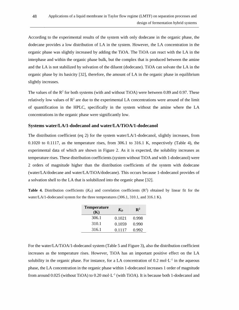
48 Applications of a liquid membrane in Taylor flow regime (LMTF) on separation processes and
design of fermentation hybrid systems
According to the experimental results of the system with only dodecane in the organic phase, the
dodecane provides a low distribution of LA in the system. However, the LA concentration in the
organic phase was slightly increased by adding the TiOA. The TiOA can react with the LA in the
interphase and within the organic phase bulk, but the complex that is produced between the amine
and the LA is not stabilized by solvation of the diluent (dodecane). TiOA can solvate the LA in the
organic phase by its basicity [32], therefore, the amount of LA in the organic phase in equilibrium
slightly increases.
The values of the R2 for both systems (with and without TiOA) were between 0.89 and 0.97. These
relatively low values of R2 are due to the experimental LA concentrations were around of the limit
of quantification in the HPLC, specifically in the system without the amine where the LA
concentrations in the organic phase were significantly low.
Systems water/LA/1-dodecanol and water/LA/TiOA/1-dodecanol
The distribution coefficient (eq 2) for the system water/LA/1-dodecanol, slightly increases, from
0.1020 to 0.1117, as the temperature rises, from 306.1 to 316.1 K, respectively (Table 4), the
experimental data of which are shown in Figure 2. As it is expected, the solubility increases as
temperature rises. These distribution coefficients (system without TiOA and with 1-dodecanol) were
2 orders of magnitude higher than the distribution coefficients of the system with dodecane
(water/LA/dodecane and water/LA/TiOA/dodecane). This occurs because 1-dodecanol provides of
a solvation shell to the LA that is solubilized into the organic phase [32].
Table 4. Distribution coefficients (KD) and correlation coefficients (R2) obtained by linear fit for the
water/LA/1-dodecanol system for the three temperatures (306.1, 310.1, and 316.1 K).
Temperature
(K) KD R2
306.1 0.1021 0.998
310.1 0.1059 0.990
316.1 0.1117 0.992
For the water/LA/TiOA/1-dodecanol system (Table 5 and Figure 3), also the distribution coefficient
increases as the temperature rises. However, TiOA has an important positive effect on the LA
solubility in the organic phase. For instance, for a LA concentration of 0.2 mol·L-1 in the aqueous
phase, the LA concentration in the organic phase within 1-dodecanol increases 1 order of magnitude
from around 0.025 (without TiOA) to 0.20 mol·L-1 (with TiOA). It is because both 1-dodecanol and

Chapter 2: Liquid-liquid equilibria of potential liquid membranes for lactic acid removal 49
TiOA can solvate the free LA in the organic phase and 1-dodecanol solvates the LA-TiOA complex
stabilizing it.
Figure 2. Experimental data (symbols) and fitted model (lines) of the liquid-liquid equilibria for the
water/LA/1-dodecanol system at three temperatures (306.1, 310.1, and 316.1 K).
In the system including TiOA (Figure 3), the chemical equilibrium constants KE,1:1 and KE,1:2 were
calculated. The chemical equilibrium constant KE,1:2 was low enough to be neglected (with an order
of magnitude of 1×10⁻³) at the three temperatures. Therefore, the 1:1 stoichiometric ratio can be
assumed for this system.
Figure 3. Experimental data (symbols) and fitted model (lines) of the liquid-liquid equilibria for the
water/LA/TiOA/1-dodecanol system at three temperatures (306.1, 310.1, and 316.1 K).

50 Applications of a liquid membrane in Taylor flow regime (LMTF) on separation processes and
design of fermentation hybrid systems
On the other hand, the chemical equilibrium constant (KE,1:1) decreases as the temperature rises
(Table 5), suggesting an exothermic reaction (ΔHrxn = -24.41 kcal·mol-1 and ΔSrxn = -0.0677
kcal·(mol·K)-1 calculated using Van’t Hoff equation[11]). The values of R2 in the fit for the proposed
model of this system (with and without TiOA) were around 0.99 at the three temperatures.
Table 5. Distribution coefficients (KD), equilibrium constants (Keq) and correlation coefficients (R2) using the
proposed ELL model for the water/LA/TiOA/1-dodecanol system for the three temperatures (306.1, 310.1,
and 316.1 K).
Temperature
(K) KD Log(Keq,1:1) Log(Keq,1:2) R2
306.1 0.0489 2.64 -2.31 0.998
310.1 0.0893 2.38 -2.30 0.997
316.1 0.1476 2.08 -2.39 0.998
Systems water/LA/dodecane/1-dodecanol and water/LA/TiOA/dodecane/1-dodecanol.
Figure 4. Experimental data (symbols) and fitted model (lines) of the liquid-liquid equilibria for the
water/LA/dodecane/1-dodecanol system at three temperatures (306.1, 310.1, and 316.1 K).
Figure 4 shows measured LLE for this system without the amine (at 39.72 mol% of 1-dodecanol in
dodecane). In this case, the distribution coefficient slightly decreases as temperature rises (Table 6).
However, this decrease is within the experimental standard deviation (from 0.029 to 0.024 at 306.1
and 316.1 K, respectively), hence, it can be considered that there is not an appreciable effect of the
temperature on the distribution coefficient, which is around of 0.02 at the three temperatures.
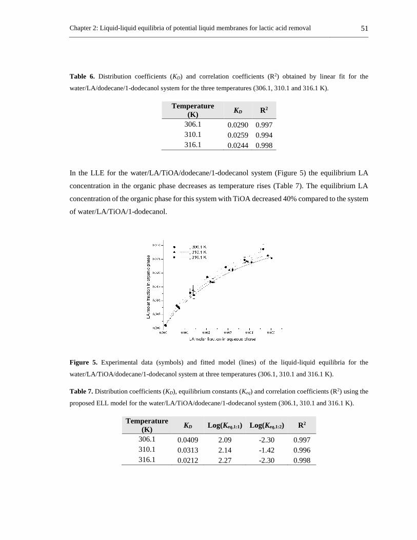
Chapter 2: Liquid-liquid equilibria of potential liquid membranes for lactic acid removal 51
Table 6. Distribution coefficients (KD) and correlation coefficients (R2) obtained by linear fit for the
water/LA/dodecane/1-dodecanol system for the three temperatures (306.1, 310.1 and 316.1 K).
Temperature
(K) KD R2
306.1 0.0290 0.997
310.1 0.0259 0.994
316.1 0.0244 0.998
In the LLE for the water/LA/TiOA/dodecane/1-dodecanol system (Figure 5) the equilibrium LA
concentration in the organic phase decreases as temperature rises (Table 7). The equilibrium LA
concentration of the organic phase for this system with TiOA decreased 40% compared to the system
of water/LA/TiOA/1-dodecanol.
Figure 5. Experimental data (symbols) and fitted model (lines) of the liquid-liquid equilibria for the
water/LA/TiOA/dodecane/1-dodecanol system at three temperatures (306.1, 310.1 and 316.1 K).
Table 7. Distribution coefficients (KD), equilibrium constants (Keq) and correlation coefficients (R2) using the
proposed ELL model for the water/LA/TiOA/dodecane/1-dodecanol system (306.1, 310.1 and 316.1 K).
Temperature
(K) KD Log(Keq,1:1) Log(Keq,1:2) R2
306.1 0.0409 2.09 -2.30 0.997
310.1 0.0313 2.14 -1.42 0.996
316.1 0.0212 2.27 -2.30 0.998

52 Applications of a liquid membrane in Taylor flow regime (LMTF) on separation processes and
design of fermentation hybrid systems
The values of the chemical equilibrium constants KE,1:2 were low enough to be neglected in this
system of water/LA/TiOA/dodecane/1-dodecanol (Table 7). An exothermic reaction is expected;
however, according to the values of the chemical equilibrium KE,1:1, the reaction adopted a slightly
endothermic behavior (ΔHrxn = 8.34 kcal·mol-1 and ΔSrxn = -0.0368 kcal·(mol·K)-1 calculated using
Van’t Hoff equation [11]). It is unclear why the chemical equilibrium constant decreases as the
temperature slightly rises. It requires additional studies to determine the structure of the nuclei
aggregates, the solvation, and the competitive complexation mechanisms of the involved substances
(water/LA/TiOA/LA-TiOA/dodecane/1-dodecanol). In the fit of this system, the values of R2 were
around 0.99.
Water co-extraction
The water concentration in the organic phase was measured for the three aforementioned systems
and it is shown in Table 8. For the system water/LA/dodecane, the water amount in the organic phase
was low and it stayed practically constant with temperature and concentration of LA, around of 0.15
wt%. The same behavior is shown for this system with TiOA, the water concentration being around
0.29 wt%. The water concentration in the first system was low, always lower than 1 wt% both with
TiOA and without TiOA; however, the water concentration in the organic phase increased almost
twice with TiOA.
In the system water/LA/1-dodecanol the maximum water concentration was 3.94 wt% at 316.1 K,
which corresponds to the highest LA concentration in the aqueous phase. The higher the temperature
and the LA concentration in the aqueous phase are, the higher the water concentration in the organic
phase will be. The water concentration is reduced to 3.03 wt% by the presence of TiOA (5.37 mol%).
Water has a higher solubility in 1-dodecanol than its solubility in the TiOA/dodecane mixture.
On the other hand, it was observed in the above LLE results that the system water/LA/TiOA/1-
dodecanol provides the highest equilibrium concentration of LA in the organic phase. The presence
of water in the organic phase supports this effect. Molecules of water within the organic phase can
interact with the extractant (TiOA) and the solute (LA) forming several nuclei aggregates. Water
provides H-bonding for solvation and even can compete with the active diluent (1-dodecanol) for
the formation of the solvation shell [32]. Therefore, the higher the amount of water in the organic
phase, the higher the solvation effect of the LA and LA-TiOA complex in the organic phase.

Chapter 2: Liquid-liquid equilibria of potential liquid membranes for lactic acid removal 53
Table 8. Water concentration in the organic phase for the liquid-liquid equilibria of the three systems at the
temperatures of 306.1, 310.1 and 316.1 K and at 77.9 kPaa at 0.2 mol% (1 g·L-1) and at 0.73 mol% (37 g·L-1)
aqueous phase.
Substances of the
organic phase Mol% T/K worg (wt%)
at the lowest LA
concentration
(0.2 mol%)
at the highest LA
concentration
(0.73 mol%)
Dodecaneb 100
306.1 0.13 0.15
310.1 0.15 0.16
316.1 0.15 0.15
Dodecane/TiOAc 94.63/5.37
306.1 0.27 0.30
310.1 0.29 0.31
316.1 0.26 0.30
1-dodecanold 100
306.1 2.91 3.32
310.1 3.22 3.70
316.1 3.60 3.94
1-dodecanol/TiOAe 94.63/5.37
306.1 1.48 2.75
310.1 2.47 3.05
316.1 2.39 3.03
Dodecane/1-
dodecanolf 39.73/60.27
306.1 0.78 1.06
310.1 0.81 0.95
316.1 0.73 0.73
Dodecane/1-
dodecanol/TiOAg 52.85/41.79/5.37
306.1 0.79 1.32
310.1 0.81 1.19
316.1 0.73 1.16 a Standard uncertainty u(T) = 0.6 K and u(P) = 0.075 kPa. b Standard uncertainties at the lowest LA concentration
ur(worg) = 0.3 and at the highest LA concentration ur(worg) = 0.2. c Standard uncertainties at the lowest LA concentration
ur(worg) = 0.3 and at the lowest LA concentration ur(worg) = 0.1. d Standard uncertainties at the lowest LA concentration
ur(worg) = 0.04 and at the lowest LA concentration ur(worg) = 0.01. e Standard uncertainties at the lowest LA concentration
ur(worg) = 0.1 and at the lowest LA concentration ur(worg) = 0.05. f Standard uncertainties at the lowest LA concentration
ur(worg) = 0.1 and at the lowest LA concentration ur(worg) = 0.1. g Standard uncertainties at the lowest LA concentration
ur(worg) = 0.05 and at the lowest LA concentration ur(worg) = 0.04.
In the systems water/LA/dodecane/1-dodecanol and water/LA/TiOA/dodecane/1-dodecanol, the
higher the LA concentration in the organic phase and the lower the temperature are, the higher is the
water concentration in the organic phase. The fact that the water concentration decreases as
temperature rises in this system can provide an explanation of why the distribution coefficients
decrease as temperature rises in the system with TiOA. In this system, water and 1-dodecanol can
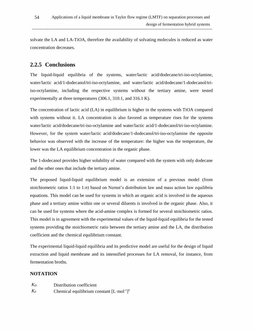
54 Applications of a liquid membrane in Taylor flow regime (LMTF) on separation processes and
design of fermentation hybrid systems
solvate the LA and LA-TiOA, therefore the availability of solvating molecules is reduced as water
concentration decreases.
2.2.5 Conclusions
The liquid-liquid equilibria of the systems, water/lactic acid/dodecane/tri-iso-octylamine,
water/lactic acid/1-dodecanol/tri-iso-octylamine, and water/lactic acid/dodecane/1-dodecanol/tri-
iso-octylamine, including the respective systems without the tertiary amine, were tested
experimentally at three temperatures (306.1, 310.1, and 316.1 K).
The concentration of lactic acid (LA) in equilibrium is higher in the systems with TiOA compared
with systems without it. LA concentration is also favored as temperature rises for the systems
water/lactic acid/dodecane/tri-iso-octylamine and water/lactic acid/1-dodecanol/tri-iso-octylamine.
However, for the system water/lactic acid/dodecane/1-dodecanol/tri-iso-octylamine the opposite
behavior was observed with the increase of the temperature: the higher was the temperature, the
lower was the LA equilibrium concentration in the organic phase.
The 1-dodecanol provides higher solubility of water compared with the system with only dodecane
and the other ones that include the tertiary amine.
The proposed liquid-liquid equilibrium model is an extension of a previous model (from
stoichiometric ratios 1:1 to 1:n) based on Nernst’s distribution law and mass action law equilibria
equations. This model can be used for systems in which an organic acid is involved in the aqueous
phase and a tertiary amine within one or several diluents is involved in the organic phase. Also, it
can be used for systems where the acid-amine complex is formed for several stoichiometric ratios.
This model is in agreement with the experimental values of the liquid-liquid equilibria for the tested
systems providing the stoichiometric ratio between the tertiary amine and the LA, the distribution
coefficient and the chemical equilibrium constant.
The experimental liquid-liquid equilibria and its predictive model are useful for the design of liquid
extraction and liquid membrane and its intensified processes for LA removal, for instance, from
fermentation broths.
NOTATION
KD Distribution coefficient
KE Chemical equilibrium constant [L·mol-1]n
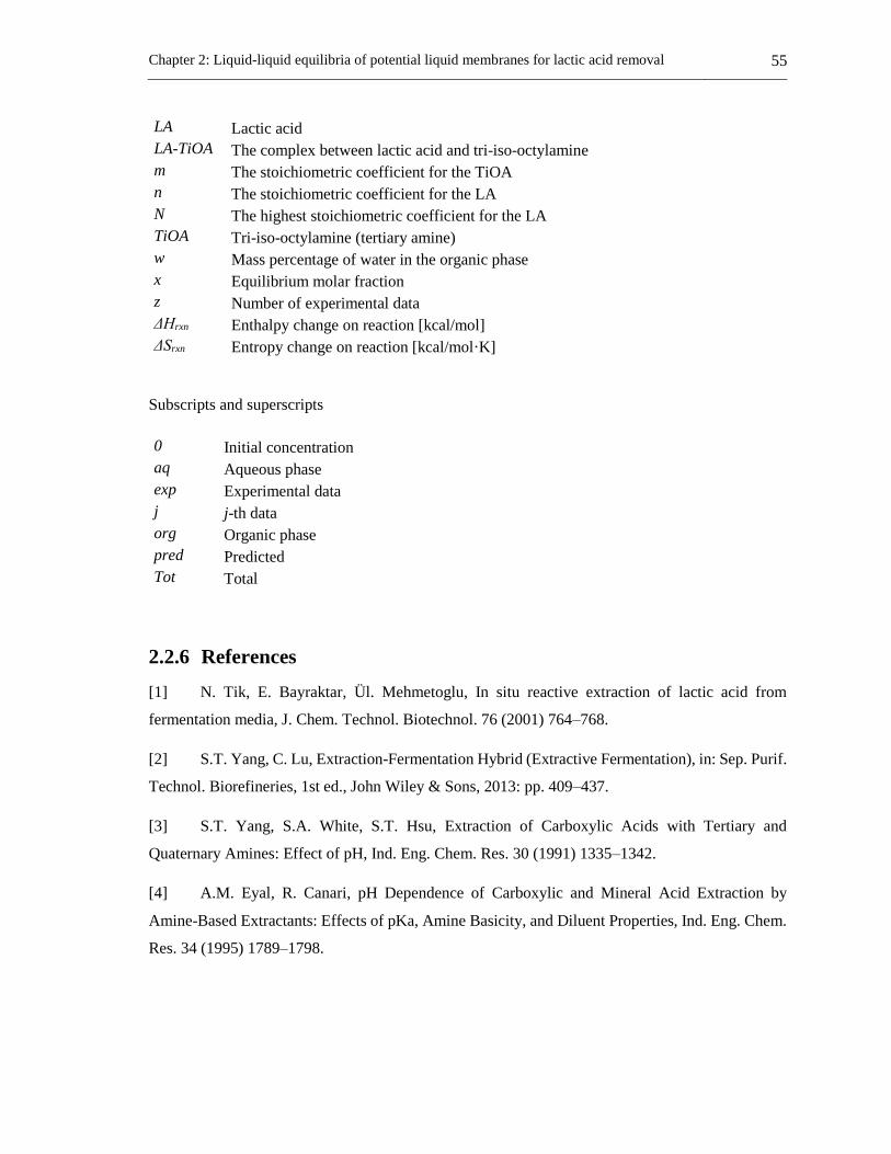
Chapter 2: Liquid-liquid equilibria of potential liquid membranes for lactic acid removal 55
LA Lactic acid
LA-TiOA The complex between lactic acid and tri-iso-octylamine
m The stoichiometric coefficient for the TiOA
n The stoichiometric coefficient for the LA
N The highest stoichiometric coefficient for the LA
TiOA Tri-iso-octylamine (tertiary amine)
w Mass percentage of water in the organic phase
x Equilibrium molar fraction
z Number of experimental data
ΔHrxn Enthalpy change on reaction [kcal/mol]
ΔSrxn Entropy change on reaction [kcal/mol·K]
Subscripts and superscripts
0 Initial concentration
aq Aqueous phase
exp Experimental data
j j-th data
org Organic phase
pred Predicted
Tot Total
2.2.6 References
[1] N. Tik, E. Bayraktar, Ül. Mehmetoglu, In situ reactive extraction of lactic acid from
fermentation media, J. Chem. Technol. Biotechnol. 76 (2001) 764–768.
[2] S.T. Yang, C. Lu, Extraction-Fermentation Hybrid (Extractive Fermentation), in: Sep. Purif.
Technol. Biorefineries, 1st ed., John Wiley & Sons, 2013: pp. 409–437.
[3] S.T. Yang, S.A. White, S.T. Hsu, Extraction of Carboxylic Acids with Tertiary and
Quaternary Amines: Effect of pH, Ind. Eng. Chem. Res. 30 (1991) 1335–1342.
[4] A.M. Eyal, R. Canari, pH Dependence of Carboxylic and Mineral Acid Extraction by
Amine-Based Extractants: Effects of pKa, Amine Basicity, and Diluent Properties, Ind. Eng. Chem.
Res. 34 (1995) 1789–1798.
56 Applications of a liquid membrane in Taylor flow regime (LMTF) on separation processes and
design of fermentation hybrid systems
[5] R. Canari, A.M. Eyal, Extraction of carboxylic acids by amine-based extractants: Apparent
extractant basicity according to the pH of half-neutralization, Ind. Eng. Chem. Res. 42 (2003) 1285–
1292.
[6] Z. Gu, B.A. Glatz, C.E. Glatz, Propionic acid production by extractive fermentation. I.
Solvent considerations, Biotechnol. Bioeng. 57 (1998) 454–461. doi:10.1002/(SICI)1097-
0290(19980220)57:4<454::AID-BIT9>3.0.CO;2-L.
[7] H. Ziegenfuß, G. Maurer, Distribution of acetic acid between water and organic solutions of
tri-n-octylamine, Fluid Phase Equilib. 102 (1994) 211–255.
[8] M. Marinova, J. Albet, J. Molinier, G. Kyuchoukov, Specific influence of the modifier (1-
Decanol) on the extraction of tartaric acid by different extractants, Ind. Eng. Chem. Res. 44 (2005)
6534–6538.
[9] S. Pandey, S. Kumar, Reactive Extraction of Gallic Acid Using Aminic and Phosphoric
Extractants Dissolved in Different Diluents: Effect of Solvent’s Polarity and Column Design, Ind.
Eng. Chem. Res. 57 (2018) 2976–2987.
[10] E. Sabolová, Š. Schlosser, J. Marták, Liquid−liquid equilibria of butyric acid in water +
solvent systems with trioctylamine as extractant, J. Chem. Eng. Data. 46 (2001) 735–745.
[11] A.D. Pérez, S. Rodríguez-Barona, J. Fontalvo, Liquid–Liquid Equilibria for
Trioctylamine/1-Dodecanol/Lactic Acid/Water System at 306.1, 310.1 and 316.1 K: Experimental
Data and Prediction, J. Chem. Eng. Data. 61 (2016) 2269–2276.
[12] K.L. Wasewar, A.A. Yawalkar, J.A. Moulijn, V.G. Pangarkar, Fermentation of Glucose to
Lactic Acid Coupled with Reactive Extraction: A Review, Ind. Eng. Chem. Res. 43 (2004) 5969–
5982. doi:10.1021/ie049963n.
[13] W. Qin, Z. Li, Y. Dai, Extraction of Monocarboxylic Acids with Trioctylamine: Equilibria
and Correlation of Apparent Reactive Equilibrium Constant, Ind. Eng. Chem. Res. 42 (2003) 6196–
6204.
[14] J.A. Tamada, C.J. King, Extraction of carboxylic acids with amine extractants. 2. Chemical
Interactions and Interpretation of Data, Ind. Eng. Chem. Res. 29 (1990) 1327–1333.
Chapter 2: Liquid-liquid equilibria of potential liquid membranes for lactic acid removal 57
[15] G. Kyuchoukov, A. Labbaci, J. Albet, J. Molinier, Simultaneous Influence of Active and
“Inert” Diluents on the Extraction of Lactic Acid by Means of Tri- n -octylamine (TOA) and Tri- iso
-octylamine (TIOA), Ind. Eng. Chem. Res. 45 (2006) 503–510. doi:10.1021/ie050912f.
[16] J. Marták, L. Kubišová, Š. Schlosser, Liquid-liquid equilibria of 5-methyl-2-
pyrazinecarboxylic and sulfuric acids for solvents with trioctylamine, J. Chem. Eng. Data. 55 (2010)
3578–3589.
[17] B. Choudhury, T. Swaminathan, Lactic acid extraction with trioctyl amine, Bioprocess Eng.
19 (1998) 317. doi:10.1007/s004490050526.
[18] D. Yankov, J. Molinier, J. Albet, G. Malmary, G. Kyuchoukov, Lactic acid extraction from
aqueous solutions with tri-n-octylamine dissolved in decanol and dodecane, Biochem. Eng. J. 21
(2004) 63–71.
[19] D.H. Han, W.H. Hong, Water-Enhanced Solubilities of Lactic Acid in Reactive Extraction
Using Trioctylamine/Various Active Diluents Systems, Sep. Sci. Technol. 33 (1998) 271–281.
doi:10.1080/01496399808544768.
[20] G. Malmary, J. Albet, A. Putranto, H. Hanine, J. Molinier, Measurement of partition
coefficients of carboxylic acids between water and triisooctylamine dissolved in various diluents, J.
Chem. Eng. Data. 43 (1998) 849–851. doi:10.1021/je980087s.
[21] A. Labbaci, G. Kyuchoukov, J. Albet, J. Molinier, Detailed investigation of lactic acid
extraction with tributylphosphate dissolved in dodecane, J. Chem. Eng. Data. 55 (2010) 228–233.
doi:10.1021/je900315r.
[22] A.F. Morales, J. Albet, G. Kyuchoukov, G. Malmary, J. Molinier, Influence of Extractant
(TBP and TOA), Diluent, and Modifier on Extraction Equilibrium of Monocarboxylic Acids, J.
Chem. Eng. Data. 48 (2003) 874–886.
[23] H. Honda, Y. Toyama, H. Takahashi, Effective lactic acid production by two-stage
extractive fermentation, J. Ferment. Bioeng. 79 (1995) 589–593.
[24] M.A. Abdel-Rahman, Y. Tashiro, K. Sonomoto, Recent advances in lactic acid production
by microbial fermentation processes., Biotechnol. Adv. 31 (2013) 877–902.
doi:10.1016/j.biotechadv.2013.04.002.
58 Applications of a liquid membrane in Taylor flow regime (LMTF) on separation processes and
design of fermentation hybrid systems
[25] F.A. Castillo Martinez, E.M. Balciunas, J.M. Salgado, J.M. Domínguez González, A.
Converti, R.P.D.S. Oliveira, Lactic acid properties, applications and production: A review, Trends
Food Sci. Technol. 30 (2013) 70–83. doi:10.1016/j.tifs.2012.11.007.
[26] D. Pinelli, F. Magelli, D. Matteuzzi, Production of L (+) and D (-) Lactic Acid Isomers by
Lactobacillus casei subsp. casei DSM 20011 and Lactobacillus coryniformis subsp. torquens DSM
20004 in Continuous Fermentation, J. Ferment. Bioeng. 81 (1996) 548–552.
[27] R. Juang, S. Lee, R. Shiau, Mass-transfer modeling of permeation of lactic acid across
amine-mediated supported liquid membranes, J. Memb. Sci. 137 (1997) 231–239.
[28] N.A. Marinova, D.S. Yankov, Toxicity of some solvents and extractants towards
Lactobacillus casei cells, Bulg. Chem. Commun. 41 (2009) 368–373.
[29] G.B. Brinques, M. Do Carmo Peralba, M.A.Z. Ayub, Optimization of probiotic and lactic
acid production by Lactobacillus plantarum in submerged bioreactor systems, J. Ind. Microbiol.
Biotechnol. 37 (2010) 205–212. doi:10.1007/s10295-009-0665-1.
[30] M. Matsumoto, T. Takagi, K. Kondo, Separation of lactic acid using polymeric membrane
containing a mobile carrier, J. Ferment. Bioeng. 85 (1998) 483–487.
[31] D. Yankov, J. Molinier, J. Albet, G. Malmary, G. Kyuchoukov, Lactic acid extraction from
aqueous solutions with tri-n-octylamine dissolved in decanol and dodecane, Biochem. Eng. J. 21
(2004) 63–71. doi:10.1016/j.bej.2004.03.006.
[32] V.S. Kislik, Solvent Extraction: Classical and Novel Approaches, 1st ed., Amsterdam, 2012.
Chapter 3: Selection of a membrane phase for in-situ lactic acid removal 59
3. Chapter 3: Selection of a membrane phase for in-situ
lactic acid removal

60 Applications of a liquid membrane in Taylor flow regime (LMTF) on separation processes and
design of fermentation hybrid systems
3.1 Molecular toxicity of potential liquid membranes for lactic
acid removal from fermentation broths using Lactobacillus
casei ATCC 3933
Abstract
Toxic effects of extractants and carriers of specific microorganisms must be taken into account
before using them with hybrid fermentation processes that are combined with liquid membranes or
liquid-liquid extraction. In the current research three extractants (trioctylamine, tri-iso-octylamine
and Aliquat 336), three diluents (dodecane, dodecanol, and oleyl alcohol) and two mixtures
(extractant/diluent) were tested for molecular toxicity on the bacteria Lactobacillus casei ATCC 393
as potential components of a liquid membrane or a liquid-liquid extraction process for lactic acid
removal in an intensified fermentation process. Glucose consumption, lactic acid production, and
cell growth were used as toxicity indicators. Physical properties of extractants and diluents were
related to the molecular toxicity on the microorganism. These results show that mixtures of tri-iso-
octylamine/dodecane and trioctylamine/dodecane at a proportion of 1:9 v/v have great potential to
be used in liquid membranes or liquid-liquid extraction processes on hybrid fermentations with
Lactobacillus casei ATCC 393.
3 This section has been published in: DYNA, 85(207), pp. 360-366, Octubre - Diciembre, 2018: Alan D. Perez,
Sneyder Rodríguez-Barona, Javier Fontalvo
Chapter 3: Selection of a membrane phase for in-situ lactic acid removal 61
3.1.1 Introduction
Removal of organic acids through liquid membranes using tertiary amines has been the focus of
several studies [1], especially for the recovery from fermentation systems. Succinic acid has been
recovered using a hollow-fiber supported liquid membrane with a trialkylamine [2]. Citric acid has
been removed using an emulsion liquid membrane with Alamine 336 [3]. Acetic acid has been
separated by emulsion liquid membranes with Amberlite LA-2 (secondary amine), trioctylamine [4],
and Aliquat 336 (quaternary ammonium salt) [5]. Lactic acid has been recovered by a supported
liquid membrane with trioctylamine [6] and by emulsion liquid membranes with both tributyl
phosphate and trioctylamine [7].
In the aforementioned perstraction and reactive liquid-liquid extraction processes, an extractant or
carrier is mixed with a diluent [1,4,8,9]. Several characteristics are required from these extractants
and solvents, for instance: low viscosity, a high difference of densities with the aqueous phase (that
contains the solute), low melting point, medium interfacial tension, high hydrophobicity, thermal
stability, low price and availability [10–12], within others. Additionally, toxicity levels of extractant
and diluent on microorganisms are key factors to take into account with liquid membranes or liquid-
liquid extractions applied for the removal of metabolites from fermentation systems.
Tertiary amines have commonly been used for organic acid removal owing to their high extraction
availability, low water solubility and high selectivity [11,13–16] which is usually due to the
formation of carboxylic acid-amine complexes [10,17]. Diluents allow for the adjustment of
viscosity and density of the solvent phase [15], and on the other hand, provide high distribution
coefficients [10]. Diluents can be inert or have an interaction with the extractant that influences its
performance. An inert diluent can improve the physical extraction without affecting the transport
mechanism [9] while an active diluent can have functional groups that interact with the carboxylic
acid-amine complex solvating it in order to stabilize the complex [9,14].
Toxic effects of a solvent on microorganisms are related with accumulation in the cytoplasmic cell
membrane. At this level, modifications are made in the functionality of the membrane proteins.
Solvents go into and disrupt the lipid bilayer. These compounds generate rupture and metabolite
leakage damage. Its effect may result in cell lysis and death [18–20]. The aforementioned toxic
effects have been related to a physical property of the substance, the logarithm of the partition
coefficient of the solvent in an equimolar mixture of n-octanol and water (Log Pow) [18,21–23]. As
lower the Log Pow is, the greater polarity and the toxicity of the solvent will be [22]. The solvent
interacts with the microorganism mainly by two routes: direct contact between the cells and the

62 Applications of a liquid membrane in Taylor flow regime (LMTF) on separation processes and
design of fermentation hybrid systems
solvent into the aqueous-organic interface (phase toxicity) and by the organic solvent that is soluble
in the aqueous broth (molecular toxicity) [19,20,24,25].
When a perstraction process is integrated with a fermentation process (hybrid process), the toxicity
of the membrane phase (diluent/extractant) on the microorganisms can rise [10,16]. Thus, additional
parameters have to be considered for designing the extraction or perstraction process including
loading ratio, complexation equilibrium constant, stoichiometry and rate constant of the organic
acid-amine complex [10,26]. In a hybrid process with in-situ product removal (ISPR) [27], either by
reactive liquid-liquid extraction or supported liquid membranes, both molecular and phase toxicity
affect cell growth and productivity. In order to reduce toxicity, filtration is used for removing
biomass from the fermentation broth [25]. However, despite performing the product removal
externally to the bioreactor, molecular toxicity can affect the microorganism.
Toxicity of several solvents has been tested on different lactic acid microorganisms. For instance,
toxicity of n-dodecane, paraffin oil, chloroform, 1,1,1-trichloroethane, carbon tetra-chloride, ethyl
laurate, n-dodecanol, tri-n-dodecylamine, and perfluorodecalin were tested on Lactobacillus
delbrueckii ATCC 9649 [28]. Also, the toxicity of Hostarex A327, trihexylphosphate,
pentaphosphine-dipentylester, diisotridecylamine, n-octanol, isodecanol, isotridecanol, oleyl alcohol
and n-alkanes (C10–C13) were measured on Rhizopus arrhizus CCM 8109 [29]. Toxic effects of
Imidazolium-based ionic liquids were tested on Lactobacillus delbruekii NRIC 1683 [24]. Toxicity
of Tributylphosphate, tridodecylamine, dioctylamine, tri-n-octylamine, Alamine 336, Aliquat 336,
1-octanol, 1-decanol, 1-dodecanol, oleyl alcohol, n-octane, n-decane, dodecane and kerosene were
evaluated on Lactobacillus casei NBMCC-1013 [20]. Almost all these studies (except [28,29]) are
based on biomass growth and/or lactic acid production.
Also, it has been shown in the scientific literature that toxicity studies of the several organic solvents
on different microorganisms have been contradictory [20], showing that the toxicity is highly related
with the type and even the kind of strain of the microorganism. On the other hand, most of the studies
have been focused on analyzing the lactic acid production and/or cell growth but rarely glucose
consumption has been taken into account.
In this work, the molecular toxicity of three diluents (dodecane, dodecanol, and oleyl alcohol) and
three carriers (trioctylamine, tri-iso-octylamine and Aliquat 336), with high potential to be used in
lactic acid removal by perstraction or reactive liquid extraction was measured on the bacteria
Lactobacillus casei ATCC 393. Also, the molecular toxicity of mixtures trioctylamine/n-dodecane

Chapter 3: Selection of a membrane phase for in-situ lactic acid removal 63
and tri-iso-octylamine/n-dodecane were evaluated at three different volumetric ratios. The toxic
effects were analyzed by measuring biomass growth, lactic acid production, and glucose
consumption.
3.1.2 Materials and methods
Molecular toxicity of n-dodecane (Merck, assay 99%), 1-dodecanol (Merck, assay 98%) and oleyl
alcohol (Merck, assay 85%) as diluents and trioctylamine (TOA, Merck, assay 93%), tri-iso-
octylamine (TiOA, Merck, assay 95%) and Aliquat 336 (Sigma-Aldrich) as extractants were
evaluated separately on cell growth of the bacteria Lactobacillus casei ATCC 393 (Microbiologics)
using MRS (Sharlau) culture media.
The experimental design for toxicity was first with pure carriers and solvents. For the solvent with
the lowest toxicity, the experiments were carried out with amine (TOA, TiOA) concentrations at
three levels in the range of concentration reported in the literature for liquid membrane or liquid
extraction applications [6,26]. Aliquat 336 was not tested in mixtures with solvent due to its high
toxicity. All experiments were carried out with duplicates.
In every single test for each pure substance, 100 mL of culture media was prepared and added into
a 250 mL glass flask. Afterward, the organic compounds were added in order to achieve a volume
ratio of 1:10 (organic compound:culture media). The six flasks, one for every organic compound (n-
dodecane, dodecanol, oleyl alcohol, TOA, TiOA, Aliquat), were shacked using a magnetic stirrer
(Velp Scientifica) at 120 rpm and constant temperature of 310 K in an incubator (Binder RI 115, ±
0.3 K) for 72 h (contact stage). Then, the agitation was stopped, each flask was transferred to
separation funnels and kept in an oven at 310 K during 72 h for phase splitting (aqueous from the
organic phase). Subsequently, the phases were separated.
Volumes of 7.5, 15, 22.5 and 30 mL of each aqueous phase, previously saturated with an organic
phase (described above), were taken and mixed with fresh culture media to reach a total volume of
30 ml using Falcon centrifuge tubes of 50 mL. These volumes correspond to proportions of 25%,
50%, 75% and 100 vol%. Then, each culture media was inoculated at 5 vol% with Lactobacillus
casei ATCC 393 from an inoculum of 12 h. One control (fermentation without toxic agents) was
prepared using fresh culture media. At the beginning of the fermentation (previous to inoculum step,
0 h) and at the end (24 h) one sample was extracted from each Falcon tube (6 (mixtures) x 4 (levels)
x 2 (duplicates) = 48 tubes) in order to quantify the glucose consumption, lactic acid and biomass
production (in percentage referred to control fermentation). Bacterial growth was measured by

64 Applications of a liquid membrane in Taylor flow regime (LMTF) on separation processes and
design of fermentation hybrid systems
optical density (OD at the maximum wavelength, 540 nm) using a spectrophotometer (V1200,
Mapada Instruments) and by dry cell weight method [30]. Lactic acid production and glucose
consumption were measured by HPLC (ELITE LaChrom) using ORH-801 column (Chrom Tech)
with a RI detector at 318.15 K using as a mobile phase a solution of 0.01 N H2SO4 (Merck, assay
95-97%) prepared with type 1 water (Barnstead™ Nanopure™). Every single Falcon tube was kept
in an oven at 310 K for 24 h.
Trioctylamine and tri-iso-octylamine were mixed at concentrations of 10, 20 and 30 vol% with n-
dodecane (0% of amine corresponds to previous experiments with pure dodecane) and its molecular
toxicity level were tested following the aforementioned procedure using 30 mL of the aqueous phase
(from the phase splitting) for the fermentation step. These concentration of the amine are typical for
liquid membranes and liquid extraction [6,13,26]. As it is shown below, Oleyl alcohol and dodecanol
were excluded due to their high toxicity compared to dodecane.
3.1.3 Results and discussion
Based on the classification of J. Marták et al. [29], organic solvents can be divided into three groups
according to their toxicity level on microorganisms. Non-toxic, when the production rate is beyond
75%, medium toxicity when the production rate is between the 25% and 75%, and toxic when the
production rate is less than 25% as compared with a control fermentation.
Molecular toxicity for pure solvents
Figures 1-3 show the relative lactic acid (LA) production, cell growth and glucose consumption of a
fermentation broth composed of a mixture of fresh culture media and saturated culture media with
the specific solvent at proportions of 25, 50, 75 and 100 vol%, (referred to the saturated culture
media). Figures 1-3 are based on a culture media that were not in contact with the studied organic
compounds (control fermentation) and for which the LA production, cell growth, and glucose
consumptions were also measured. Taking into account the Marták criteria [29], dodecane was non-
toxic for the four tested proportions. Cell growth and LA production were still 16% lower than the
control fermentation at the four proportions, while glucose consumption was still 6% higher. For
dodecane molecular toxicity test, the glucose concentration in the culture media increases after the
contact stage due to the transport of water and some nutrients from the culture media to the organic
phase. Thus, the glucose concentration of the saturated culture media was between 1.4% and 5.3%
(SD = 1.5 – 7.6%), higher than the control fermentation, and in consequence, the glucose
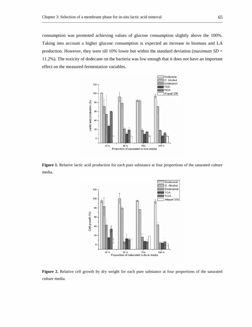
Chapter 3: Selection of a membrane phase for in-situ lactic acid removal 65
consumption was promoted achieving values of glucose consumption slightly above the 100%.
Taking into account a higher glucose consumption is expected an increase in biomass and LA
production. However, they were till 10% lower but within the standard deviation (maximum SD =
11.2%). The toxicity of dodecane on the bacteria was low enough that it does not have an important
effect on the measured fermentation variables.
Figure 1. Relative lactic acid production for each pure substance at four proportions of the saturated culture
media.
Figure 2. Relative cell growth by dry weight for each pure substance at four proportions of the saturated
culture media.

66 Applications of a liquid membrane in Taylor flow regime (LMTF) on separation processes and
design of fermentation hybrid systems
Oleyl alcohol was non-toxic for volumetric proportions from 25 to 75% considering LA production,
cell growth, and glucose consumption (with a minimum and maximum standard deviation of ±0.9
and ±19.6). However, it can be observed that for cell growth (Figure 2) at proportions from 25 to
75%, alcohol can be classified as medium toxic if the standard deviations are taking into account.
Oleyl alcohol was medium toxic for a proportion of 100% based on LA production, cell growth, and
glucose consumption (with a minimum and maximum standard deviation of ±5.6 and ±18). The
glucose consumption (Figure 3) was reduced by 20% for 25, 50 and 75% proportions and it was
reduced by 30% for a proportion of 100%. On the other hand, both cell growth and LA production
decrease around 20% for proportions of 25, 50 and 75% and around 30% for a proportion of 100%.
These results seem to indicate that the bacteria use glucose equitably to produce LA and biomass
when oleyl alcohol is present.
Figure 3. Relative glucose consumption for each pure substance at four proportions of the saturated culture
media.
Dodecanol has a medium toxicity for a proportion of 25%, and it was toxic for the other proportions
based on LA production and cell growth (Figure 1). However, glucose consumption was reduced
around 40% for a proportion of 25% and around 60% for proportions of 50, 75% and 100%. Also,
cell growth rate was reduced by 60% for a proportion of 25% and around 90% for proportions of 50,
75% and 100%. LA production was reduced around 50% for a proportion of 25% and around 80%
for the other proportions. The aforementioned results show that the bacteria consumes more glucose
to survive than the biomass and LA produced. It uses this glucose for maintenance and this behavior
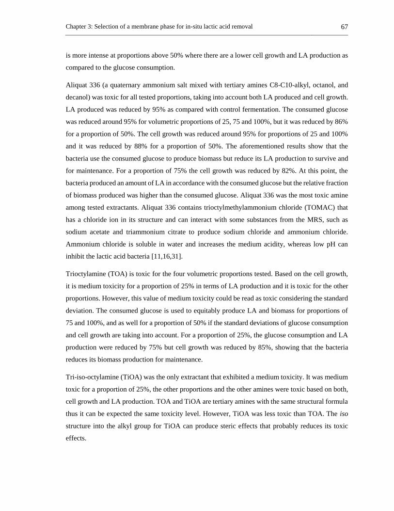
Chapter 3: Selection of a membrane phase for in-situ lactic acid removal 67
is more intense at proportions above 50% where there are a lower cell growth and LA production as
compared to the glucose consumption.
Aliquat 336 (a quaternary ammonium salt mixed with tertiary amines C8-C10-alkyl, octanol, and
decanol) was toxic for all tested proportions, taking into account both LA produced and cell growth.
LA produced was reduced by 95% as compared with control fermentation. The consumed glucose
was reduced around 95% for volumetric proportions of 25, 75 and 100%, but it was reduced by 86%
for a proportion of 50%. The cell growth was reduced around 95% for proportions of 25 and 100%
and it was reduced by 88% for a proportion of 50%. The aforementioned results show that the
bacteria use the consumed glucose to produce biomass but reduce its LA production to survive and
for maintenance. For a proportion of 75% the cell growth was reduced by 82%. At this point, the
bacteria produced an amount of LA in accordance with the consumed glucose but the relative fraction
of biomass produced was higher than the consumed glucose. Aliquat 336 was the most toxic amine
among tested extractants. Aliquat 336 contains trioctylmethylammonium chloride (TOMAC) that
has a chloride ion in its structure and can interact with some substances from the MRS, such as
sodium acetate and triammonium citrate to produce sodium chloride and ammonium chloride.
Ammonium chloride is soluble in water and increases the medium acidity, whereas low pH can
inhibit the lactic acid bacteria [11,16,31].
Trioctylamine (TOA) is toxic for the four volumetric proportions tested. Based on the cell growth,
it is medium toxicity for a proportion of 25% in terms of LA production and it is toxic for the other
proportions. However, this value of medium toxicity could be read as toxic considering the standard
deviation. The consumed glucose is used to equitably produce LA and biomass for proportions of
75 and 100%, and as well for a proportion of 50% if the standard deviations of glucose consumption
and cell growth are taking into account. For a proportion of 25%, the glucose consumption and LA
production were reduced by 75% but cell growth was reduced by 85%, showing that the bacteria
reduces its biomass production for maintenance.
Tri-iso-octylamine (TiOA) was the only extractant that exhibited a medium toxicity. It was medium
toxic for a proportion of 25%, the other proportions and the other amines were toxic based on both,
cell growth and LA production. TOA and TiOA are tertiary amines with the same structural formula
thus it can be expected the same toxicity level. However, TiOA was less toxic than TOA. The iso
structure into the alkyl group for TiOA can produce steric effects that probably reduces its toxic
effects.

68 Applications of a liquid membrane in Taylor flow regime (LMTF) on separation processes and
design of fermentation hybrid systems
Although it is known that toxicity of organic solvents depend on the type of microorganism or even
of its strain [10,29,34], generally the toxicity is related to the solvent polarity (related to Log Pow
values - Table 1) [1,19,24], and its water solubility [10,25]. Therefore, it is expected that dodecanol
and oleyl alcohol, which are polar, were more toxic than dodecane (non-polar). The toxicity with the
alkane is similar to other studies where alkanes were non-toxic or low toxic on bacteria [29,35]. For
alcohols, it is known that its toxicity decreases as its long-chain increases [1,29,35,36]. Also, this
study shows that oleyl alcohol (C18) is less toxic than dodecanol (C12) on the bacteria Lactobacillus
casei ATCC 393 (Figure 2).
Table 1. Main physical properties of the tested solvents related with its toxicity on microorganisms.
Substance Water solubility [g L-1]
at 298.15 K Log Pow
Surface tension [dyn
cm-1] at 298.15 K
Dodecanol 0.004 4.56 31.01
Oleyl alcohol Insoluble 7.05 34.39
Dodecane Practically insoluble 5.44 22.53
Aliquat 336 Practically insoluble 9.79b 39.53b
TOA < 0.0001 9.46 32.50
TiOA < 1a 9.25 29.19 Physical properties were calculated with ProPed-ICAS 14 software (CAPEC-DTU) using Marrero and Gani,
Constantinou and Gani methods [32,33]. Water solubility was taken from MSDS. aPhysical property at 293.15 K.
bPhysical property calculated for TOMAC using connectivity index neglecting ionic bond.
The logarithm of Pow (Table 1) is a common parameter to study toxic effects on microorganisms
[24,37]. A Log Pow higher than 4, apparently does not have any effect on the biocatalytic activity of
the cell [37]. However, a type of Lactobacillus Delbruekii is sensitive to organic solvents with Log
Pow between 1 to 4 [24]. Taking into account Log Pow as a parameter of toxicity [24,37], the tested
solvents can be considered to be low toxic, except dodecanol that it can be considered as non-toxic
due to its Log Pow value, nevertheless, another scientific literature have shown that Log Pow is an
unreliable parameter [1] to infer the toxicity level. However, other parameters as solubility and
surface tension can affect the microbial growth (biomass and LA production, and glucose
consumption).
Surface tension and water solubility have also been used to predict the toxic effect of the solvent on
the microorganism. A high surface tension involves a rapid loss of cellular activity [19,37] where
the cell membrane fluidity increases [19]. Also, the lower the solvent solubility in water is, the lower
the probability of contact between the solvent and the microorganism will be. Thus, microorganisms
will be less affected for the solvent presence into the culture media. For these reasons oleyl alcohol

Chapter 3: Selection of a membrane phase for in-situ lactic acid removal 69
is less toxic than dodecanol (water solubility in Table 1) in spite of having a similar surface tension.
And dodecane has a low toxicity because it has a lower surface tension and lower water solubility
than dodecanol and Oleyl alcohol.
In extractants, the higher the surface tension is the higher the toxicity on the bacteria will be, resulting
Aliquat 336 with the highest toxicity in spite of being the extractant with the lowest water solubility.
The lower toxicity of TiOA as compared with TOA is due to TOA has a higher surface tension and
in consequence, it disturbs the cell membrane function as a barrier, as a matrix for enzymes and as
energy transducer [23].
Molecular toxicity of selected mixtures
Figures 4-6 shows lactic acid production, cell growth and glucose consumption (respectively) for the
culture media after contact with mixes of TiOA or TOA (less toxic amines) in dodecane (less toxic
diluent) at volumetric proportions of 10, 20 and 30% of the respective tertiary amine in dodecane.
Figure 4. Lactic acid production for TiOA/dodecane and TOA/dodecane mixtures at three proportions of the
tertiary amine.
TiOA mixed in n-dodecane was non-toxic at the three volumetric proportions for both, LA
production and cell growth. For cell growth, the toxicity effect on the bacteria rises as the TiOA
concentration increases, being non-toxic for volumetric proportions of 10 and 20% and medium toxic
at 30%. There is a LA production according to the glucose consumption for three proportions of
TiOA. However, as TiOA concentration rises, the cell growth decreases, perhaps in order to survive
due to a high energy consumption of the bacteria trying to tolerate the organic solvent. These
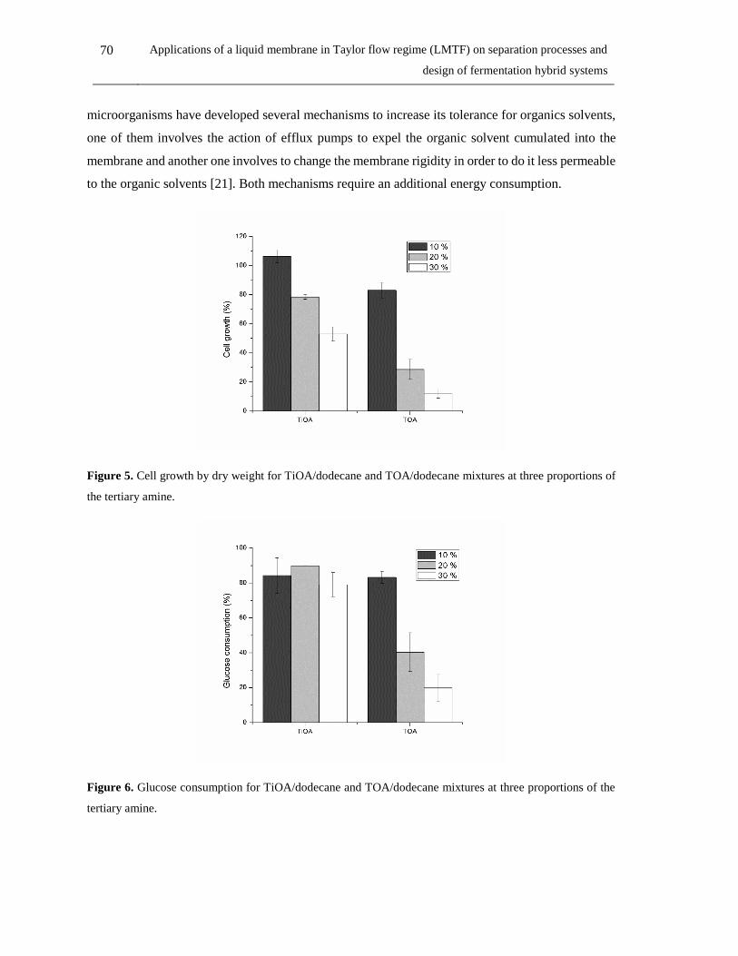
70 Applications of a liquid membrane in Taylor flow regime (LMTF) on separation processes and
design of fermentation hybrid systems
microorganisms have developed several mechanisms to increase its tolerance for organics solvents,
one of them involves the action of efflux pumps to expel the organic solvent cumulated into the
membrane and another one involves to change the membrane rigidity in order to do it less permeable
to the organic solvents [21]. Both mechanisms require an additional energy consumption.
Figure 5. Cell growth by dry weight for TiOA/dodecane and TOA/dodecane mixtures at three proportions of
the tertiary amine.
Figure 6. Glucose consumption for TiOA/dodecane and TOA/dodecane mixtures at three proportions of the
tertiary amine.
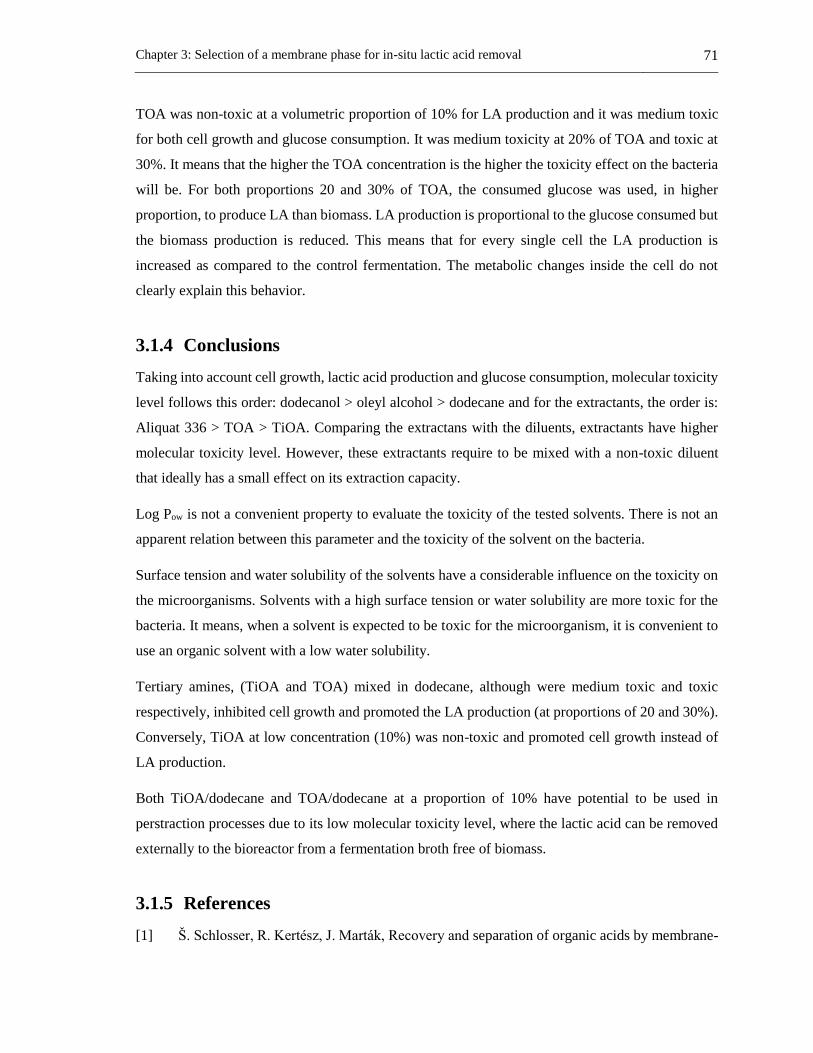
Chapter 3: Selection of a membrane phase for in-situ lactic acid removal 71
TOA was non-toxic at a volumetric proportion of 10% for LA production and it was medium toxic
for both cell growth and glucose consumption. It was medium toxicity at 20% of TOA and toxic at
30%. It means that the higher the TOA concentration is the higher the toxicity effect on the bacteria
will be. For both proportions 20 and 30% of TOA, the consumed glucose was used, in higher
proportion, to produce LA than biomass. LA production is proportional to the glucose consumed but
the biomass production is reduced. This means that for every single cell the LA production is
increased as compared to the control fermentation. The metabolic changes inside the cell do not
clearly explain this behavior.
3.1.4 Conclusions
Taking into account cell growth, lactic acid production and glucose consumption, molecular toxicity
level follows this order: dodecanol > oleyl alcohol > dodecane and for the extractants, the order is:
Aliquat 336 > TOA > TiOA. Comparing the extractans with the diluents, extractants have higher
molecular toxicity level. However, these extractants require to be mixed with a non-toxic diluent
that ideally has a small effect on its extraction capacity.
Log Pow is not a convenient property to evaluate the toxicity of the tested solvents. There is not an
apparent relation between this parameter and the toxicity of the solvent on the bacteria.
Surface tension and water solubility of the solvents have a considerable influence on the toxicity on
the microorganisms. Solvents with a high surface tension or water solubility are more toxic for the
bacteria. It means, when a solvent is expected to be toxic for the microorganism, it is convenient to
use an organic solvent with a low water solubility.
Tertiary amines, (TiOA and TOA) mixed in dodecane, although were medium toxic and toxic
respectively, inhibited cell growth and promoted the LA production (at proportions of 20 and 30%).
Conversely, TiOA at low concentration (10%) was non-toxic and promoted cell growth instead of
LA production.
Both TiOA/dodecane and TOA/dodecane at a proportion of 10% have potential to be used in
perstraction processes due to its low molecular toxicity level, where the lactic acid can be removed
externally to the bioreactor from a fermentation broth free of biomass.
3.1.5 References
[1] Š. Schlosser, R. Kertesz, J. Marták, Recovery and separation of organic acids by membrane-
72 Applications of a liquid membrane in Taylor flow regime (LMTF) on separation processes and
design of fermentation hybrid systems
based solvent extraction and pertraction, Sep. Purif. Technol. 41 (2005) 237–266.
doi:10.1016/j.seppur.2004.07.019.
[2] S.-J. Li, H.-L. Chen, L. Zhang, Recovery of fumaric acid by hollow-fiber supported liquid
membrane with strip dispersion using trialkylamine carrier, Sep. Purif. Technol. 66 (2009)
25–34. doi:10.1016/j.seppur.2008.12.004.
[3] B. Yordanov, L. Boyadzhiev, Pertraction of citric acid by means of emulsion liquid
membranes, J. Memb. Sci. 238 (2004) 191–197. doi:10.1016/j.memsci.2004.04.004.
[4] S.C. Lee, K.-S. Hyun, Development of an emulsion liquid membrane system for separation
of acetic acid from succinic acid, J. Memb. Sci. 350 (2010) 333–339.
doi:10.1016/j.memsci.2010.01.008.
[5] S.C. Lee, Development of an emulsion liquid membrane system for removal of acetic acid
from xylose and sulfuric acid in a simulated hemicellulosic hydrolysate, Sep. Purif. Technol.
118 (2013) 540–546. doi:10.1016/j.seppur.2013.07.032.
[6] R.-S. Juang, S.-H. Lee, R.-C. Shiau, Mass-transfer modeling of permeation of lactic acid
across amine-mediated supported liquid membranes, J. Memb. Sci. 137 (1997) 231–239.
doi:10.1016/S0376-7388(97)00206-8.
[7] J. Yuanli, Modeling of the permeation swelling of emulsion during lactic acid extraction by
liquid surfactant membranes, J. Memb. Sci. 191 (2001) 215–223. doi:10.1016/S0376-
7388(01)00470-7.
[8] J. Berrios, D.L. Pyle, G. Aroca, Gibberellic acid extraction from aqueous solutions and
fermentation broths by using emulsion liquid membranes, J. Memb. Sci. 348 (2010) 91–98.
doi:10.1016/j.memsci.2009.10.040.
[9] G. Kyuchoukov, A. Labbaci, J. Albet, J. Molinier, Simultaneous Influence of Active and
“Inert” Diluents on the Extraction of Lactic Acid by Means of Tri- n -octylamine (TOA) and
Tri- iso -octylamine (TIOA), Ind. Eng. Chem. Res. 45 (2006) 503–510.
doi:10.1021/ie050912f.
[10] K.L. Wasewar, A.A. Yawalkar, J.A. Moulijn, V.G. Pangarkar, Fermentation of Glucose to
Lactic Acid Coupled with Reactive Extraction: A Review, Ind. Eng. Chem. Res. 43 (2004)
5969–5982. doi:10.1021/ie049963n.
Chapter 3: Selection of a membrane phase for in-situ lactic acid removal 73
[11] C.S. López-Garzón, A.J.J. Straathof, Recovery of carboxylic acids produced by fermentation,
Biotechnol. Adv. 32 (2014) 873–904. doi:10.1016/j.biotechadv.2014.04.002.
[12] M. Jung, B. Schierbaum, H. Vogel, Extraction of Carboxylic Acids from Aqueous Solutions
with the Extractant System Alcohol/Trin-Alkylamines, Chem. Eng. Technol. 23 (2000) 70–
74. doi:10.1002/(SICI)1521-4125(200001)23:1<70::AID-CEAT70>3.0.CO;2-O.
[13] B. Choudhury, T. Swaminathan, Lactic acid extraction with trioctyl amine, Bioprocess Eng.
19 (1998) 317. doi:10.1007/s004490050526.
[14] D.H. Han, W.H. Hong, Water-Enhanced Solubilities of Lactic Acid in Reactive Extraction
Using Trioctylamine/Various Active Diluents Systems, Sep. Sci. Technol. 33 (1998) 271–
281. doi:10.1080/01496399808544768.
[15] J.A. Tamada, A.S. Kertes, C.J. King, Extraction of carboxylic acids with amine extractants.
1. Equilibria and law of mass action modeling, Ind. Eng. Chem. Res. 29 (1990) 1319–1326.
doi:10.1021/ie00103a035.
[16] D. Yankov, J. Molinier, G. Kyuchoukov, J. Albet, G. Malmary, Improvement of the Lactic
Acid Extraction . Extraction From Aqueous Solutions and Simulated Fermentation Broth by
Means of Mixed Extractant and TOA , Partially Loaded with HCl, Chem. Biochem. Eng. Q.
19 (2005) 17–24. http://silverstripe.fkit.hr/cabeq/assets/Uploads/Cabeq-2005-01-3.pdf.
[17] M. Hossain, Mass Transfer Investigation of Organic Acid Exatraction with Trioctylamine
and Aliquat 336 Dissolved in Various Solvents, in: Mass Transf. Multiph. Syst. Its Appl.,
InTech, 2011: pp. 367–388. doi:10.5772/15276.
[18] J.L. Ramos, E. Duque, M.-T. Gallegos, P. Godoy, M.I. Ramos-González, A. Rojas, W. Terán,
A. Segura, Mechanisms of Solvent Tolerance in Gram-Negative Bacteria, Annu. Rev.
Microbiol. 56 (2002) 743–768. doi:10.1146/annurev.micro.56.012302.161038.
[19] Z. Gu, B.A. Glatz, C.E. Glatz, Propionic acid production by extractive fermentation. I.
Solvent considerations, Biotechnol. Bioeng. 57 (1998) 454–461. doi:10.1002/(SICI)1097-
0290(19980220)57:4<454::AID-BIT9>3.0.CO;2-L.
[20] N.A. Marinova, D.S. Yankov, Toxicity of some solvents and extractants towards
Lactobacillus casei cells, Bulg. Chem. Commun. 41 (2009) 368–373.
http://www.bcc.bas.bg/BCC_Volumes/Volume_41_Number_4_2009/Volume_41_Number
_4_2009_PDF/2916-AC.pdf.

74 Applications of a liquid membrane in Taylor flow regime (LMTF) on separation processes and
design of fermentation hybrid systems
[21] P. Fernandes, Solvent tolerance in bacteria: role of efflux pumps and cross-resistance with
antibiotics, Int. J. Antimicrob. Agents. 22 (2003) 211–216. doi:10.1016/S0924-
8579(03)00209-7.
[22] Y. Sardessai, S. Bhosle, Tolerance of bacteria to organic solvents, Res. Microbiol. 153 (2002)
263–268. doi:10.1016/S0923-2508(02)01319-0.
[23] S. Isken, J.A.M. de Bont, Bacteria tolerant to organic solvents, Extremophiles. 2 (1998) 229–
238. doi:10.1007/s007920050065.
[24] M. Matsumoto, K. Mochiduki, K. Kondo, Toxicity of ionic liquids and organic solvents to
lactic acid-producing bacteria, J. Biosci. Bioeng. 98 (2004) 344–347. doi:10.1016/S1389-
1723(04)00293-2.
[25] V.M. Yabannavar, D.I.C. Wang, Strategies for reducing solvent toxicity in extractive
fermentations, Biotechnol. Bioeng. 37 (1991) 716–722. doi:10.1002/bit.260370805.
[26] A.D. Pérez, S. Rodríguez-Barona, J. Fontalvo, Liquid–Liquid Equilibria for Trioctylamine/1-
Dodecanol/Lactic Acid/Water System at 306.1, 310.1 and 316.1 K: Experimental Data and
Prediction, J. Chem. Eng. Data. 61 (2016) 2269–2276. doi:10.1021/acs.jced.5b00955.
[27] J.M. Woodley, M. Bisschops, A.J.J. Straathof, M. Ottens, Future directions for in-situ product
removal (ISPR), J. Chem. Technol. Biotechnol. 83 (2008) 121–123. doi:10.1002/jctb.1790.
[28] R. Bar, J.L. Gainer, Acid Fermentation in Water-Organic Solvent Two-Liquid Phase
Systems, Biotechnol. Prog. 3 (1987) 109–114. doi:10.1002/btpr.5420030208.
[29] J. Marták, E. Sabolová, Š. Schlosser, M. Rosenberg, L. Kristofíková, Toxicity of organic
solvents used in situ in fermentation of lactic acid by Rhizopus arrhizus, Biotechnol. Tech.
11 (1997) 71–75. doi:10.1023/A:1018408220465.
[30] K. Hayakawa, H. Sansawa, T. Nagamune, I. Endo, High density culture of lactobacillus casei
by a Cross-Flow culture method based on kinetic properties of the microorganism, J. Ferment.
Bioeng. 70 (1990) 404–408. doi:10.1016/0922-338X(90)90122-D.
[31] K. Hetényi, Á. Németh, B. Sevella, Role of pH-regulation in lactic acid fermentation: Second
steps in a process improvement, Chem. Eng. Process. Process Intensif. 50 (2011) 293–299.
doi:10.1016/j.cep.2011.01.008.

Chapter 3: Selection of a membrane phase for in-situ lactic acid removal 75
[32] J. Marrero, R. Gani, Group-contribution based estimation of pure component properties,
Fluid Phase Equilib. 183–184 (2001) 183–208. doi:10.1016/S0378-3812(01)00431-9.
[33] L. Constantinou, R. Gani, New group contribution method for estimating properties of pure
compounds, AIChE J. 40 (1994) 1697–1710. doi:10.1002/aic.690401011.
[34] M.J. Playne, B.R. Smith, Toxicity of organic extraction reagents to anaerobic bacteria,
Biotechnol. Bioeng. 25 (1983) 1251–1265. doi:10.1002/bit.260250508.
[35] D. Yankov, J. Molinier, J. Albet, G. Malmary, G. Kyuchoukov, Lactic acid extraction from
aqueous solutions with tri-n-octylamine dissolved in decanol and dodecane, Biochem. Eng.
J. 21 (2004) 63–71. doi:10.1016/j.bej.2004.03.006.
[36] R. Chen, Y.Y. Lee, Membrane-mediated extractive fermentation for lactic acid production
from cellulosic biomass, Appl. Biochem. Biotechnol. 63–65 (1997) 435–448.
doi:10.1007/BF02920444.
[37] V.M. Yabannavar, D.I.C. Wang, Bioreactor System with Solvent Extraction for Organic Acid
Production, Ann. N. Y. Acad. Sci. 506 (1987) 523–535. doi:10.1111/j.1749-
6632.1987.tb23847.x.

76 Applications of a liquid membrane in Taylor flow regime (LMTF) on separation processes and
design of fermentation hybrid systems
3.2 Liquid-liquid equilibrium and molecular toxicity of active
and inert diluents of the organic mixture tri-iso-
octylamine/dodecanol/dodecane as a potential liquid
membrane for lactic acid removal4
Abstract
Lactic acid can be in-situ removed from a fermentation broth through reactive liquid extraction or a
liquid membrane to enhance the fermentation process. The organic mixture tri-iso-octylamine
(TiOA)/dodecanol/dodecane at 10 vol% of the amine is a potential organic mixture for lactic acid
removal. Liquid-liquid equilibria with lactic acid aqueous solutions and molecular toxicity on the
bacteria Lactobacillus casei ATCC 393 were measured with several dodecanol proportions in
dodecane (0 to 90 vol%) and 10 vol% TiOA as potential solvents or membrane phases for LA
removal from a fermentation broth. Effects of the organic phase on the bacteria as cell growth,
biomass production, glucose consumption, productivity and product to biomass yield are analyzed.
Dodecanol increases the lactic acid chemical equilibrium constant for the liquid-liquid equilibria,
while increases the molecular toxicity on the bacteria. However, for dodecanol concentrations from
30 to 40 vol% the value of the chemical equilibrium constant is high enough for lactic acid
distribution between the phases and its toxicity is low enough on the bacteria, making a proper range
of dodecanol concentrations for lactic acid removal. Also, the distribution coefficient and the
chemical equilibrium constant are fitted as function of the dodecanol concentration in the organic
mixture.
4 This section has published in: J. Chem. Eng. Data 2019, Article ASAP: Alan D. Perez, Verónica M. Gómez,
Sneyder Rodríguez-Barona, Javier Fontalvo.

Chapter 3: Selection of a membrane phase for in-situ lactic acid removal 77
3.2.1 Introduction
Lactic acid (LA) is a commodity chemical [1,2] which can be obtained by chemical synthesis or by
carbohydrate fermentation [3–5]. The 90% of the LA is produced by biotechnological route [4,6].
However, in the conventional process for LA production, the bacterial growth is inhibited on the one
hand by LA, achieving low concentrations of LA, and on the other hand by substrate, limiting initial
substrate concentration within the bioreactor [1,7,8]. Besides, this process requires multiple
separation steps for recovery and purification of the LA from the fermentation broth [1,2,9]. The
whole LA production process is expensive [1,2], and 50% of the total cost is due to the separation
and final purification steps [1,2,9].
LA biotechnological production requires an enhancement on its production process that avoid the
common drawbacks of the conventional process, which are cell growth inhibition (by product and
substrate), the use of neutralizers, low yield and productivity, and high overall costs of the process
[2]. Several separation technologies, such as solvent extraction, adsorption (with and without ion
exchange), distillation, filtration, ultrafiltration, nanofiltration, electrodialysis, reverse osmosis,
evaporation, crystallization, and liquid membranes have been tested for LA recovery from
fermentation broths as promising alternatives over the conventional process [1,9,10].
In-situ LA removal using one or several of the aforementioned separation technologies is a potential
strategy to overcome the typical drawbacks of LA production [1,10]. In-situ LA removal reduces
end-product inhibition [1] and contributes to the fed-batch or continuous operation of the
fermentation [7]. One of the most extensively studied separation technologies for LA removal has
been reactive extraction [11–16]. However, this process requires high amounts of solvent and the
use of back-extraction for regeneration of the solvent [8,17].
Perstraction is a liquid membrane process which can use the same solvent (diluent and extractant) of
reactive extraction as membrane phase [18]. It does not require high amounts of solvent, and the
extraction and back-extraction processes are combined in a single device [17,18]. This process is
also called liquid membrane, and several studies using this membrane technology have been focused
on LA removal [19–27].
Usually, the selection of the solvent, for either reactive extraction or liquid membranes, is based on
the ability of the solvent to enhance the LA removal from the fermentation broth and the toxic effect
of the solvent on the specific microorganism in the fermentation broth [28,29]. However, most of
the solvents used for LA removal from fermentation broths are toxic on the specific microorganism
[28].
78 Applications of a liquid membrane in Taylor flow regime (LMTF) on separation processes and
design of fermentation hybrid systems
There are two kinds of toxicity of the solvent on the microorganism depending on the type of contact
between the solvent and the microorganism. On the one hand, molecular toxicity is due to the soluble
portion of the solvent in the fermentation broth. On the other hand, phase level toxicity is due to the
presence of two phases in the fermentation process, solvent phase and fermentation broth phase
[30,31]. For in-situ LA removal using reactive extraction or liquid membranes, both levels of toxicity
can affect the microorganism. However, filtration is usually used for removing biomass from the
fermentation broth to avoid phase toxicity on the microorganism [32]. However, performing biomass
filtration and product removal externally to the bioreactor will leave molecular toxicity to occur on
the microorganism [33]. There are several cellular responses due to toxic organic solvents, such as
stress [34], changes in cell morphology (filamentation) [34,35], cell surface modification
(hydrophobic shift) [34], cell membrane adaptions (membrane fluidity) [34,35] and solvent excretion
through efflux pumps [34,35], among others. Most of these cellular responses are energy demanding
[36].
Single alcohols and tertiary amines mixed within alkanes or alcohols have extensively studied for
LA removal because they have shown high extraction capabilities [11–16,22,37–39]. The liquid-
liquid equilibrium of the mixture tri-octylamine at 0.8 M (around 23 mol%) in 1-dodecanol with LA
aqueous solutions have shown a high value of the chemical equilibrium constant [12], becoming it
as a potential solvent for reactive extraction or potential membrane phase for liquid membrane
processes. However, toxicity studies are required for the selection of these organic compounds in an
in-situ LA removal process either by liquid-liquid extraction or liquid membrane processes.
Molecular toxicity of pure 1-dodecanol, n-dodecane, oleyl alcohol, Aliquiat 336, tri-octylamine and
tri-iso-octylamine (TiOA) were tested in a previous work [33], showing that n-dodecane is non-toxic
on the Lactobacillus casei ATCC 393 (probiotic and homofermentative bacteria which the main
metabolite is lactic acid). Depending on the concentration of oleyl alcohol within the fermentation
broth, it can be classified between non-toxic or with medium toxicity. 1-dodecanol has medium
toxicity, and the tertiary amines are toxic on the bacteria. However, tri-iso-octylamine at a low
concentration within the fermentation broth (concentrations of TiOA 50% lower than saturation
point on the fermentation broth) has medium toxicity. Also, the toxicity of the mixture
TiOA/dodecane on the same bacteria was tested at 10, 20 and 30 vol% of TiOA (5.40, 11.38 and
18.04 mol%) showing that the mixture at 5.40 and 11.38 mol% is non-toxic and at 18.04 mol% is
medium toxic [33].
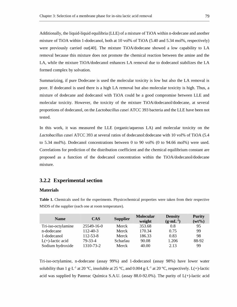
Chapter 3: Selection of a membrane phase for in-situ lactic acid removal 79
Additionally, the liquid-liquid equilibria (LLE) of a mixture of TiOA within n-dodecane and another
mixture of TiOA within 1-dodecanol, both at 10 vol% of TiOA (5.40 and 5.34 mol%, respectively)
were previously carried out[40]. The mixture TiOA/dodecane showed a low capability to LA
removal because this mixture does not promote the chemical reaction between the amine and the
LA, while the mixture TiOA/dodecanol enhances LA removal due to dodecanol stabilizes the LA
formed complex by solvation.
Summarizing, if pure Dodecane is used the molecular toxicity is low but also the LA removal is
poor. If dodecanol is used there is a high LA removal but also molecular toxicity is high. Thus, a
mixture of dodecane and dodecanol with TiOA could be a good compromise between LLE and
molecular toxicity. However, the toxicity of the mixture TiOA/dodecanol/dodecane, at several
proportions of dodecanol, on the Lactobacillus casei ATCC 393 bacteria and the LLE have been not
tested.
In this work, it was measured the LLE (organic/aqueous LA) and molecular toxicity on the
Lactobacillus casei ATCC 393 at several ratios of dodecanol:dodecane with 10 vol% of TiOA (5.4
to 5.34 mol%). Dodecanol concentrations between 0 to 90 vol% (0 to 94.66 mol%) were used.
Correlations for prediction of the distribution coefficient and the chemical equilibrium constant are
proposed as a function of the dodecanol concentration within the TiOA/dodecanol/dodecane
mixture.
3.2.2 Experimental section
Materials
Table 1. Chemicals used for the experiments. Physicochemical properties were taken from their respective
MSDS of the supplier (each one at room temperature).
Name CAS Supplier Molecular
weight
Density
(g·mL-1)
Purity
(wt%)
Tri-iso-octylamine 25549-16-0 Merck 353.68 0.8 95
n-dodecane 112-40-3 Merck 170.34 0.75 99
1-dodecanol 112-53-8 Merck 186.33 0.83 98
L(+)-lactic acid 79-33-4 Scharlau 90.08 1.206 88-92
Sodium hydroxide 1310-73-2 Merck 40.00 2.13 99
Tri-iso-octylamine, n-dodecane (assay 99%) and 1-dodecanol (assay 98%) have lower water
solubility than 1 g·L-1 at 20 °C, insoluble at 25 °C, and 0.004 g·L-1 at 20 °C, respectively. L(+)-lactic
acid was supplied by Panreac Química S.A.U. (assay 88.0-92.0%). The purity of L(+)-lactic acid
80 Applications of a liquid membrane in Taylor flow regime (LMTF) on separation processes and
design of fermentation hybrid systems
(extra pure) was assessed by titration with NaOH (assay ≥ 99.0%) using Metrohm automatic titrator
(702 SM Titrino, 703 TI Stand). A stock solution of lactic acid (150 g/L) was heated at 90 °C under
total reflux between 8-10 hours for dimer hydrolysis [15,41], and afterward, the lactic acid
concentration was measured by titration. Type I water was used for all aqueous solutions
(Barnstead™ Nanopure™). All chemicals used are listed in Table 1. Lactobacillus casei ATCC 393
(Microbiologics) was used for fermentations with MRS broth (Scharlau) as culture media.
Liquid-liquid equilibria experiments (LLE)
LLE experiments for organic phases with 10 vol% (5.40 to 5.34 mol%) of TiOA (extractant or
carrier) in n-dodecane (inert diluent) and 1-dodecanol (active diluent) with concentrations of 1-
dodecanol of 10, 20, 30 and 50 vol% were performed (10.62, 21,22, 31.79 and 52.85 mol%). For the
LLE experiments and each of the above organic phases, 5 vials of 10 mL were filled with 2 mL of
an aqueous solution of LA, at concentrations between 1 and 38 g/L (0.0166 and 0.6465 mol%). Then,
2 mL of the organic phase was added to each vial. The experimental procedure was performed at a
constant temperature (37 °C) and consist in the next three steps [12]: agitation, decantation, and
sampling. First, all vials were shaken at 180 rpm (Wiseshake Shot-1D, Wisd) with an incubator
(Wisd, ± 0.6 K) during 72 h. Afterward, the agitation was stopped, and the vials were kept into the
incubator (decantation step) during 72 h. One sample of the aqueous solution was taken from every
single vial, and its lactic acid concentration was measured by high-performance liquid
chromatography (HPLC ELITE LaChrom). For HPLC analysis, it was used an ORH-801 column
(Chrom Tech) with a solution of 0.01 N H2SO4 (Merck, assay 95-97%) for the mobile phase, and a
RI detector at 45 °C. The LA concentration in equilibrium within the organic phase was calculated
by a material balance [12].
The measured LA concentrations at equilibrium were used to fit the distribution coefficient (eq 1)
and the chemical equilibrium constant (eq 2) based on a LLE model developed in previous works
[12,40]. Brackets in equations 1 and 2 represent molar concentrations
aq
org
DLA
LAK
][
][ (1)
orgorg
org
ETiOALA
TiOALAK (2)

Chapter 3: Selection of a membrane phase for in-situ lactic acid removal 81
The LA in the organic phase can be as free LA, which comes from the aqueous phase by diffusion,
and as LA-TiOA complex, which is the LA that reacts with the amine both the organic-aqueous
interface and the bulk of organic phase [12,40]. For the distribution coefficient, the LA concentration
in the organic phase corresponds to the LA in its free form.
Molecular toxicity test
Toxicity of TiOA in 1-dodecanol at 5.34 mol% of TiOA was measured on the bacteria Lactobacillus
casei ATCC 393 as shown elsewhere [33]. MRS broth was prepared according to the manufacturer
instructions (Scharlau). 3 mL of the organic phase was added in a falcon tube with 30 mL of sterile
MRS. The Falcon tube was shaken by 72 h at 180 rpm (Wiseshake Shot-1D, Wisd) at 37 °C into a
bod incubator (Wisd, ± 0.6 K). Afterward, the shaker was stopped, the falcon tubes were kept in the
incubator at the same temperature for 72 h to reach phase splitting (aqueous phase from the organic
phase). Then, the aqueous phases (culture media saturated with the organic phase) were separated
from the organic phase by splitting. Each culture media within a new sterile falcon tube was
inoculated at 5 vol% from a culture of 12 h.
One control fermentation was prepared using fresh culture media (MRS without contact with the
organic phase). The fermentation of each inoculated falcon tube was kept into a bod incubator (Wisd,
± 0.6 K) for 24 h at 37 °C. Samples from each falcon tube were taken at the beginning (0 h) and at
the end (24 h) of each fermentation for measuring the percentage of bacterial growth, LA production
and glucose consumption based on the control fermentation. Bacterial growth was measured by dry
cell weight method [33]. LA production and glucose consumption were measured by HPLC using
the same method of LA measurements in the LLE experiments.
The aforementioned procedure also was used to test the molecular toxicity of organic phases with
10 vol% of TiOA (5.40 to 5.34 mol%) in n-dodecane and at 1-dodecanol proportions of 10, 20, 30,
40, 50 and 90 vol% (0, 10.62, 21.22, 31.79, 42.33, 52.85 and 94.66 mol%, respectively). All
experiments were performed by duplicate.
3.2.3 Results and discussion
Liquid-liquid equilibria
The distribution coefficient and the chemical equilibrium constant for the LLE of aqueous LA
solutions in contact with tri-iso-octylamine/n-dodecane/1-dodecanol at 37 ºC increases as the
concentration of dodecanol in the organic mixture rises (Figure 1). In the organic phase, there was

82 Applications of a liquid membrane in Taylor flow regime (LMTF) on separation processes and
design of fermentation hybrid systems
always TiOA at 10 vol% (5.40 to 5.34 mol%) and the proportion dodecane to dodecanol varied.
Dodecane is an inert diluent and dodecanol is an active diluent [40]. Dodecanol provides a solvation
shell for the free LA and for the LA complex in the organic phase [40], which stabilizes the acid-
amine complex. Therefore, the availability of the dodecanol molecules to solvate is enhanced with
an increase of dodecanol concentration in the organic phase.
The stoichiometric ratio (amine:acid) 1:1 is the most common for these systems where a tertiary
amine is involved and especially when the LA concentration is low (lower than the stoichiometric
concentration [40]). Therefore, it was used a stoichiometric ratio of 1:1 for fitting the values of KD
and KE for all dodecanol concentrations from 0 to 94.66 mol% (Figure 1) using a previous LLE
model [40]. For the organic mixture without dodecanol there is not complex formation, and the value
of KE is zero [40].
Figure 1. Fitted values of the distribution coefficient (squares) and the chemical equilibrium constants
(triangles) with its respective correlations (continuous line) using eqs 3 and 4, respectively. Values of KD and
KE at 0, 42.33 and 94.66 mol% of dodecanol were taking from a previous work [40].
The increase of the KE with dodecanol concentration was monotonic, while for the KD it does not
show a proportional increase (Figure 1). For KD it was used a third-grade polynomial fit (eq 3) while
for the KE it was used eq 4, which is a Langmuir equation. For both fits, a molar concentration of
dodecanol was used. The corresponding fitted parameters are presented in Table 2 with their
corresponding correlation coefficients.
01
2
2
3
3 aDOHaDOHaDOHaK D (3)

Chapter 3: Selection of a membrane phase for in-situ lactic acid removal 83
DOHK
DOHKKK E
2
211
(4)
Generally, in systems that used tertiary amines, most of the organic acid within the organic phase is
due to a LA-Amine complex that it is formed with the tertiary amine [12,40]. Therefore, the amount
of free LA within the organic phase in equilibrium is very small as compared to the LA-TiOA
complex [40]. Thus, KE provides more valuable information to determine which organic mixture
provides a better capacity to remove the LA than KD.
Table 2. Fitted parameters of eqs 3 and 4 with its corresponding correlation coefficients.
R2 a3 (L·mol-1)3 a2 (L·mol-1)2 a1 (L·mol-1) a0
0.9977 1.9987 -0.6186 0.1010 0.0194
R2 K1 (L·mol-1) K2 (L·mol-1)
0.9863 485.18 2.3060
Molecular toxicity test
Figure. 2. Relative cell growth, lactic acid production and glucose consumption as compared to a control
fermentation of the saturated media with TiOA/dodecanol/dodecane at 10 vol% of TiOA (5.4 to 5.34 mol%)
and at proportions of dodecanol of 0, 10.62, 21.22, 31.79, 42.33, 52.85 and 94.66 mol% at 37 °C. Molecular
toxicity for dodecanol proportion of 0 mol% was previously reported [33].
Molecular toxicity of the mixtures TiOA/dodecanol/dodecane at concentrations of dodecanol from
0 to 94.66 mol% on the bacteria Lactobacillus casei ATCC 393 is shown in Figure 2. The level of
toxicity was classified according to J. Marták et al. [29], where the toxicity level is divided into three

84 Applications of a liquid membrane in Taylor flow regime (LMTF) on separation processes and
design of fermentation hybrid systems
categories. Non-toxic, when the production rate is beyond 75%, medium toxicity when the
production rate is between the 25% and 75% and toxic when the production rate is less than 25% as
compared with control fermentation.
Surface tension and water solubility are properties that can be related to toxicity levels of the solvent
on a specific microorganism [33]. The toxicity of solvents increases as its surface tension rises
because a high surface tension leads to a rapid loss of cellular activity [28,42]. On the other hand,
the higher the water solubility of the solvent, the higher the probability of contact between the
bacteria and the organic solvent [33]. The surface tension of dodecanol and dodecane are 31.01 and
22.53 dyn/cm (at 25 °C), respectively, and its water solubility for dodecanol is 0.004 g/L (at 25 °C),
and dodecane is practically insoluble. Both physical properties are higher for dodecanol than for
dodecane. Therefore, it is expected an increase of toxicity as the dodecanol concentration within the
organic phase increases.
The mixture TiOA/dodecanol/dodecane at 0 mol% of dodecanol (Figure 2) is non-toxic taking into
account cell growth, lactic acid production, and glucose consumption. Cell growth is not affected by
the presence of the solubilized organic compounds of the organic phase into the culture media.
However, LA production and glucose consumption slight decreases compared with control
fermentation. Glucose consumption is 84.31%, while LA production is 89.54% of the values of the
control fermentation. The bacteria response to the presence of the organic solvents, within the
fermentation broth, in several ways [34,35] such as hydrophobic shift on cell surface to repel
hydrophobic compounds [34], and homeoviscous adaptation that increases membrane rigidity
because the degree of membrane fatty acid saturation also increases [34]. Perhaps these effects may
affect the mechanism of glucose transport through the membrane cell or phosphotransferase system
for sugars (PTS), making the glucose consumption of the bacteria lower than the control
fermentation. The bacteria probably does not have enough ATP to support this mechanism.
The mixture TiOA/dodecanol/dodecane with 10.62 mol% of dodecanol is non-toxic, and mixtures
with concentrations of dodecanol from 21.22 to 52.85 mol% are medium toxicity. For the organic
mixtures TiOA/dodecanol/dodecane with dodecanol proportions from 10.62 to 52.86 mol%, the
lactic acid production is around 5% higher than glucose consumption, while the biomass production
is lower (between 6 and 25% below) than the LA production and the glucose consumption. Some of
the responses of the cells to the toxic compounds are activation of efflux pumps, change the
morphology, surface adaptations, among others, which are energy demanding [36]. Thus, it is
probable that this additional energy requirement of the cells, as a mechanism to adapt or survive to

Chapter 3: Selection of a membrane phase for in-situ lactic acid removal 85
toxic compounds, directly affects the cell growth. The energy is used by the cell to activate one of
several mechanisms to tolerate the toxic compounds within the fermentation broth instead to use it
entirely for cell growth.
The mixture TiOA/dodecanol/dodecane at 94.66 mol% of dodecanol is toxic for cell growth, LA
production, and glucose consumption according to the results showed in Figure 2. The glucose
consumption is reduced as compared to control fermentation, probably because the glucose transport
is affected by the hydrophobic shift on surface cell and homeoviscous adaptation in membrane cell,
as responses of the bacteria to the toxic compounds. Glucose consumption is affected in the same
proportion than LA production (around 19%). However, the cell growth is affected in a higher
proportion achieving a bacterial growing of 4% of the one in the control fermentation. The low
biomass production can be due to the bacteria kept the consumed glucose for maintenance instead
of biomass production. Thus, the bacteria requires additional energy to use the efflux pumps to take
out the toxic solvent from the bacteria increasing energy requirement on the bacteria. Therefore, the
cells reduce the energy consumption for biomass production.
In Figure 2, it can be observed that for dodecanol concentration of 94.66 mol% (which means 0
mol% of dodecane) in the mixture TiOA/dodecanol/dodecane, the cell growth is lower than LA
production, while for a dodecanol proportion of 0 mol% (which corresponds to 94.6 mol% of
dodecane) the cell growth is higher than LA production. Therefore, the effect of that the LA
production is promoted instead cell growth can be attributed to the presence of dodecanol within the
fermentation broth, while the effect that cell growth is promoted instead LA production can be
attributed to the presence of dodecane within the fermentation broth. Additionally, it is observed that
for dodecanol concentrations from 10.62 to 52.85 mol%, the LA production is promoted instead the
cell growth in spite of that dodecane is also present within the fermentation broth (Figure 2). It means
that the dodecanol effect on the bacteria is stronger than the effect of dodecane on the bacteria.
Most of the published literature on molecular toxicity of organic compound on specific bacteria have
shown in their results the toxic effect on cell growth. Only a few ones have taken into account both,
the main metabolite production and the substrate consumption. In this work, it is observed that
evaluating these three parameters is important to determine whether cell growth or main metabolite
production is promoted. However, in spite of these results it is still unclear how these organic
compounds interact within the bacteria or on its metabolism which could be explore in the future.
The relative LA productivity between the LA productivity of the fermentation saturated with the
organic phase and the LA productivity of the control fermentation is around the unit for dodecanol
86 Applications of a liquid membrane in Taylor flow regime (LMTF) on separation processes and
design of fermentation hybrid systems
concentrations between 0 to 21.22 mol%. However, the fermentation saturated with the organic
phase at 10.62 mol% of dodecanol leads to the maximum relative LA productivity, being around 1.4
(Figure 3). This effect is due to dodecanol at this concentration promotes LA production instead of
cell growth. Also, the toxic effects on the bacteria are low, and cell growth, LA production, and
glucose consumption are similar to the control fermentation. At this dodecanol concentration, the
cell growth is reduced around 18% as compared with the control fermentation (Figure 2), while the
LA production is increased around 7% (Figure 2). For dodecanol concentrations between 21.22 to
94.66 mol%, the relative LA productivity is lower than the unit and decreases as dodecanol
concentration rises due to the toxic effect of the dodecanol on the bacteria (Figure 3).
Figure 3. Effect of the dodecanol concentration on the organic phase (TiOA/dodecanol/dodecane) on the
productivity ratio (squares) and on yield lactic acid to biomass ratio (triangles). Both are the ratio of the
fermentations saturated of the organic phase with the control.
The relative LA to biomass yield is higher than the unit at all dodecanol concentrations (Figure 3),
except for a dodecanol concentration of 0 mol% (which was 0.98 ± 0.17), where the cell growth is
slightly promoted instead LA production. The relative LA to biomass yield changes between 1 and
1.6 for dodecanol concentrations between 0 to 52.85 mol% (within of the organic phase
TiOA/dodecanol/dodecane). A maximum LA to biomass yield of 6.6 is reached for a dodecanol
concentration of 94.66 mol%, where the LA production was promoted instead cell growth. Relative
LA to biomass yields higher than the unit is due to biomass growth is always lower than the LA
produced, except for a dodecanol concentration of 0 mol%.
Chapter 3: Selection of a membrane phase for in-situ lactic acid removal 87
However, a high LA to biomass yield does not mean a high LA productivity as compared to the
control fermentation. At the highest relative LA to biomass yield, it is obtained the lowest LA and
biomass concentrations (Figure 2) due to the high toxicity level.
3.2.4 Conclusions
Molecular toxicity on the Lactobacillus casei ATCC 393 and liquid-liquid equilibria within aqueous
lactic acid, for mixtures of TiOA/dodecane, TiOA/dodecanol, both at 10 vol% (5.4 mol%) of TiOA,
and TiOA/dodecanol/dodecane at a TiOA concentration of 10 vol% (5.4 to 5.34 mol%) and
dodecanol concentrations of 0, 10.62, 21.22, 31.79, 42.33, 52.85 and 94.66 mol% were measured.
Both, the distribution coefficient and the chemical equilibrium constant are higher for the mixture
TiOA/dodecanol than for the mixture TiOA/dodecane. However, the mixture TiOA/dodecanol was
toxic on the bacteria, while the mixture TiOA/dodecane was non-toxic on the bacteria.
For the systems containing TiOA/dodecane/dodecanol in the organic phase, at several ratios
dodecanol to dodecane, the distribution coefficient and the chemical equilibrium constant (KE)
increase as dodecanol concentration rises. However, the organic mixture at a dodecanol
concentration of 10.62 mol% is non-toxic on the bacteria, while at dodecanol concentrations from
21.22 to 52.85 mol% were medium toxicity.
Cell growth is promoted instead of glucose consumption and LA production when the culture media
is saturated with TiOA/dodecane. Glucose consumption and LA production are promoted instead
cell growth when the culture media is saturated with TiOA/dodecanol. Even, the last behavior occurs
for all organic phases with dodecanol, regardless of the presence of dodecane in these organic
mixtures.
The highest value of KE is achieved for the mixture TiOA/dodecanol, but the organic mixture is toxic
on the bacteria. The values of KE are quite similar (around 150 L·mol-1) at dodecanol concentrations
of 31.78, 42.33 and 52.85 mol%, where the organic mixtures are medium toxicity. The mixtures of
TiOA/dodecanol/dodecane at dodecanol concentrations between of 31.79 and 42.33 mol% have a
good compromise between a high value of KE and a relatively low molecular toxicity.
NOTATION
ai Fitted parameters in eq 3
K1 Fitted parameter eq 4 [L·mol-1]
K2 Fitted parameter eq 4 [L·mol-1]

88 Applications of a liquid membrane in Taylor flow regime (LMTF) on separation processes and
design of fermentation hybrid systems
KD Distribution coefficient
KE Chemical equilibrium constant [L·mol-1]
DOH Dodecanol
HPLC High performance liquid chromatography
LA Lactic acid
LA-TiOA The complex between lactic acid and tri-iso-octylamine
LLE Liquid-liquid equilibria
Subscripts
aq Aqueous phase
org Organic phase
3.2.5 References
[1] K.L. Wasewar, A.A. Yawalkar, J.A. Moulijn, V.G. Pangarkar, Fermentation of Glucose to
Lactic Acid Coupled with Reactive Extraction: A Review, Ind. Eng. Chem. Res. 43 (2004) 5969–
5982. doi:10.1021/ie049963n.
[2] M. Singhvi, T. Zendo, K. Sonomoto, Free lactic acid production under acidic conditions by
lactic acid bacteria strains: challenges and future prospects, Appl. Microbiol. Biotechnol. 102 (2018)
5911–5924. doi:10.1007/s00253-018-9092-4.
[3] P. Pal, J. Sikder, S. Roy, L. Giorno, Process intensification in lactic acid production: A
review of membrane based processes, Chem. Eng. Process. Process Intensif. 48 (2009) 1549–1559.
[4] A. Komesu, M.R. Wolf Maciel, R. Maciel Filho, Separation and Purification Technologies
for Lactic Acid – A Brief Review, BioResources. 12 (2017) 6885–6901.
doi:10.15376/biores.12.3.6885-6901.
[5] T. Ghaffar, M. Irshad, Z. Anwar, T. Aqil, Z. Zulifqar, A. Tariq, M. Kamran, N. Ehsan, S.
Mehmood, Recent trends in lactic acid biotechnology: A brief review on production to purification,
J. Radiat. Res. Appl. Sci. 7 (2014) 222–229. doi:10.1016/j.jrras.2014.03.002.
[6] J. Vijayakumar, R. Aravindand, T. Viruthagiri, Recent Trends in the Production, Purification
and Application of Lactic Acid, Chem. Biochem. Eng. Q. 22 (2008) 245–264.
https://hrcak.srce.hr/24811.
Chapter 3: Selection of a membrane phase for in-situ lactic acid removal 89
[7] M. Othman, A.B. Ariff, H. Wasoh, M.R. Kapri, M. Halim, Strategies for improving
production performance of probiotic Pediococcus acidilactici viable cell by overcoming lactic acid
inhibition, AMB Express. 7 (2017). doi:10.1186/s13568-017-0519-6.
[8] M. Othman, A.B. Ariff, L. Rios-Solis, M. Halim, Extractive fermentation of lactic acid in
lactic acid bacteria cultivation: A review, Front. Microbiol. 8 (2017) 1–7.
doi:10.3389/fmicb.2017.02285.
[9] A. Demirci, J.C. Cotton, A.L. Pometto, K.R. Harkins, P.N. Hinz, Resistance of Lactobacillus
casei in plastic-composite-support biofilm reactors during liquid membrane extraction and
optimization of the lactic acid extraction system., Biotechnol. Bioeng. 83 (2003) 749–59.
[10] N. Phanthumchinda, S. Thitiprasert, S. Tanasupawat, S. Assabumrungrat, N. Thongchul,
Process and cost modeling of lactic acid recovery from fermentation broths by membrane-based
process, Process Biochem. 68 (2018) 205–213. doi:10.1016/j.procbio.2018.02.013.
[11] Susanti, J.G.M. Winkelman, B. Schuur, H.J. Heeres, J. Yue, Lactic Acid Extraction and
Mass Transfer Characteristics in Slug Flow Capillary Microreactors, Ind. Eng. Chem. Res. 55 (2016)
4691–4702.
[12] A.D. Pérez, S. Rodríguez-Barona, J. Fontalvo, Liquid–Liquid Equilibria for
Trioctylamine/1-Dodecanol/Lactic Acid/Water System at 306.1, 310.1 and 316.1 K: Experimental
Data and Prediction, J. Chem. Eng. Data. 61 (2016) 2269–2276.
[13] A. Krzyzaniak, B. Schuur, A.B. De Haan, Equilibrium studies on lactic acid extraction with
N,N-didodecylpyridin-4-amine (DDAP) extractant, Chem. Eng. Sci. 109 (2014) 236–243.
[14] A. Krzyzaniak, M. Leeman, F. Vossebeld, T.J. Visser, B. Schuur, A.B. De Haan, Novel
extractants for the recovery of fermentation derived lactic acid, Sep. Purif. Technol. 111 (2013) 82–
89.
[15] D. Yankov, J. Molinier, J. Albet, G. Malmary, G. Kyuchoukov, Lactic acid extraction from
aqueous solutions with tri-n-octylamine dissolved in decanol and dodecane, Biochem. Eng. J. 21
(2004) 63–71.
[16] R. Juang, R. Huang, Equilibrium studies on reactive extraction of lactic acid with an amine
extractant, Chem. Eng. J. 65 (1997) 47–53.
[17] R.D. Noble, S.A. Stern, Membrane Separations Technology: Principles and Applications,

90 Applications of a liquid membrane in Taylor flow regime (LMTF) on separation processes and
design of fermentation hybrid systems
3rd ed., Elsevier, Amsterdan, 2003.
[18] V.S. Kislik, Liquid Membranes Principles & Applications in Chemical Separation &
Wastewater Treatment, 1st ed., Elsevier B.V., Amsterdan, 2010.
[19] A.D. Pérez, B. Van der Bruggen, J. Fontalvo, Study of overall mass transfer coefficients in
a liquid membrane in Taylor flow regime: Calculation and correlation, Chem. Eng. Process. - Process
Intensif. 134 (2018) 20–27.
[20] A. Kumar, A. Thakur, P.S. Panesar, Lactic acid extraction using environmentally benign
Green emulsion ionic liquid membrane, J. Clean. Prod. 181 (2018) 574–583.
doi:10.1016/j.jclepro.2018.01.263.
[21] F. Garavand, S.H. Razavi, I. Cacciotti, Synchronized extraction and purification of L-lactic
acid from fermentation broth by emulsion liquid membrane technique, J. Dispers. Sci. Technol. 39
(2018) 1291–1299. doi:10.1080/01932691.2017.1396225.
[22] N. Rastogi, B.S. Chanukya, Supported Liquid Membrane Composed of Tertiary or/and
Quaternary Amine for the Extraction of Lactic Acid, Int. J. Membr. Sci. Technol. 2 (2015) 19–28.
doi:10.15379/2410-1869.2015.02.02.03.
[23] A. Manzak, O. Tutkun, The extraction of lactic acid by emulsion type of liquid membranes
using alamine 336 in escaid 100, Can. J. Chem. Eng. 89 (2011) 1458–1463. doi:10.1002/cjce.20501.
[24] R. Juang, S. Lee, R. Shiau, Mass-transfer modeling of permeation of lactic acid across
amine-mediated supported liquid membranes, J. Memb. Sci. 137 (1997) 231–239.
[25] R. Chen, Y.Y. Lee, Membrane-mediated extractive fermentation for lactic acid production
from cellulosic biomass, Appl. Biochem. Biotechnol. 63–65 (1997) 435–448.
doi:10.1007/BF02920444.
[26] R. Juang, R. Huang, Separation of citric and lactic acids in aqueous solutions by solvent
extraction and liquid membrane processes, J. Memb. Sci. 136 (1997) 89–99.
[27] C. Schöller, J.B. Chaudhuri, D.L. Pyle, Emulsion liquid membrane extraction of lactic acid
from aqueous solutions and fermentation broth, Biotechnol. Bioeng. 42 (1993) 50–58.
doi:10.1002/bit.260420108.
[28] Z. Gu, B.A. Glatz, C.E. Glatz, Propionic acid production by extractive fermentation. I.
Chapter 3: Selection of a membrane phase for in-situ lactic acid removal 91
Solvent considerations, Biotechnol. Bioeng. 57 (1998) 454–461. doi:10.1002/(SICI)1097-
0290(19980220)57:4<454::AID-BIT9>3.0.CO;2-L.
[29] J. Marták, E. Sabolová, Š. Schlosser, M. Rosenberg, L. Kristofíková, Toxicity of organic
solvents used in situ in fermentation of lactic acid by Rhizopus arrhizus, Biotechnol. Tech. 11 (1997)
71–75. doi:10.1023/A:1018408220465.
[30] B. Choudhury, A. Basha, T. Swaminathan, Study of Lactic Acid Extraction with Higher
Molecular Weight Aliphatic Amines, J. Chem. Technol. Biotechnol. 72 (1998) 111–116.
[31] A. Demirci, A.L. Pometto, K.R. Harkins, Rapid screening of solvents and carrier compounds
for lactic acid recovery by emulsion liquid extraction and toxicity on Lactobacillus casei (ATCC
11443), Bioseparation. 7 (1999) 297–308.
[32] V.M. Yabannavar, D.I.C. Wang, Strategies for reducing solvent toxicity in extractive
fermentations, Biotechnol. Bioeng. 37 (1991) 716–722. doi:10.1002/bit.260370805.
[33] A.D. Pérez, S. Rodríguez-Barona, J. Fontalvo, Molecular toxicity of potential liquid
membranes for lactic acid removal from fermentation broths using Lactobacillus casei ATCC 393,
Dyna. 85 (2018) 360–366. doi:10.15446/dyna.v85n207.72374.
[34] S. Torres, A. Pandey, G.R. Castro, Organic solvent adaptation of Gram positive bacteria:
Applications and biotechnological potentials, Biotechnol. Adv. 29 (2011) 442–452.
doi:10.1016/j.biotechadv.2011.04.002.
[35] H. Kusumawardhani, R. Hosseini, J.H. de Winde, Solvent Tolerance in Bacteria: Fulfilling
the Promise of the Biotech Era?, Trends Biotechnol. 36 (2018) 1025–1039.
doi:10.1016/j.tibtech.2018.04.007.
[36] A. Segura, L. Molina, S. Fillet, T. Krell, P. Bernal, J. Muñoz-Rojas, J.L. Ramos, Solvent
tolerance in Gram-negative bacteria, Curr. Opin. Biotechnol. 23 (2012) 415–421.
doi:10.1016/j.copbio.2011.11.015.
[37] C.S. López-Garzón, A.J.J. Straathof, Recovery of carboxylic acids produced by
fermentation, Biotechnol. Adv. 32 (2014) 873–904. doi:10.1016/j.biotechadv.2014.04.002.
[38] N. Tik, E. Bayraktar, Ül. Mehmetoglu, In situ reactive extraction of lactic acid from
fermentation media, J. Chem. Technol. Biotechnol. 76 (2001) 764–768.
[39] W. Qin, Z. Li, Y. Dai, Extraction of Monocarboxylic Acids with Trioctylamine: Equilibria
92 Applications of a liquid membrane in Taylor flow regime (LMTF) on separation processes and
design of fermentation hybrid systems
and Correlation of Apparent Reactive Equilibrium Constant, Ind. Eng. Chem. Res. 42 (2003) 6196–
6204.
[40] A.D. Pérez, S. Rodríguez-Barona, J. Fontalvo, Liquid–Liquid Equilibria of Lactic
Acid/Water Solutions in Tri-iso-octylamine/Dodecane/1-Dodecanol at 306.1, 310.1, and 316.1 K.
Experimental Data and Prediction, J. Chem. Eng. Data. submited (2019) acs.jced.8b00794.
doi:10.1021/acs.jced.8b00794.
[41] M. Matsumoto, T. Takagi, K. Kondo, Separation of lactic acid using polymeric membrane
containing a mobile carrier, J. Ferment. Bioeng. 85 (1998) 483–487.
[42] V.M. Yabannavar, D.I.C. Wang, Bioreactor System with Solvent Extraction for Organic
Acid Production, Ann. N. Y. Acad. Sci. 506 (1987) 523–535. doi:10.1111/j.1749-
6632.1987.tb23847.x.

Chapter 4: Liquid membrane in Taylor flow 93
4. Chapter 4: Liquid membrane in Taylor flow

94 Applications of a liquid membrane in Taylor flow regime (LMTF) on separation processes and
design of fermentation hybrid systems
4.1 A new concept of liquid membranes in Taylor flow:
performance for lactic acid removal5
Abstract
A liquid membrane in Taylor flow regime is a novel alternative kind of contact in three phase flow
for liquid membranes that preserves the advantages of conventional emulsion liquid membranes
while overcomes the stability problems of emulsion systems. As a proof of concept, this work
presents experimental results of a liquid membrane in Taylor flow for lactic acid removal. Several
operating conditions, such as injection times, delay times and flow of the membrane phase were
tested for a channel length and inner diameter of 348.8 cm and 2.5 mm, respectively. The lactic acid
removal is mainly affected by the driving force of lactic acid concentrations between donor droplets
and the membrane interface, and the space-time. Thus, the lactic acid removal process through the
liquid membrane in Taylor flow is enhanced at low injection times and high droplet velocity
considering that enough space-time is provided. This technology results promising as an alternative
to conventional liquid membranes and the intensification of chemical and fermentative processes.
5 This section has been published in: Chemical Engineering & Processing: Process Intensification 139 (2019)
95–102, Alan D. Perez, Javier Fontalvo.

Chapter 4: Liquid membrane in Taylor flow 95
4.1.1 Introduction
Liquid membranes
In a liquid membrane (LM) process three fluid phases are continuously in contact [1]: membrane
phase (M), donor phase (D) and receiving phase (R). Membrane phase is an immiscible
semipermeable barrier which separates the donor phase from the receiving phase [1,2]. The donor
phase contains the solute that is transported from the donor to the receiving phase through the
membrane phase. Transport process in liquid membranes involves both liquid-liquid extraction
(LLE) and membrane separation in a single device [1]. Usually, the membrane phase is organic [1,2]
and comprises a solvent of the LLE process which can include a carrier. When the carrier is within
the membrane phase, it reacts spontaneously, rapidly and reversibly with the solute of the donor
phase forming a complex which is transported from the D/M interphase to M/R interphase (facilitated
transport), and here, the solute is released to the receiving phase [1].
LMs is a perstraction process that is classified as bulk (BLM), supported (SLM) and emulsion (ELM)
liquid membranes according to its configuration [1]. BLMs are commonly used for mass transport
and kinetic studies at lab-scale because it is limited by its low specific interface area [2]. SLMs and
ELM have potential on applications in industrial scale because they provide large interfacial areas,
extraction and stripping are in one stage, simple operation and it is possible to process high quantities
of compounds (from donor phase) using small volumes of the membrane phase [1,3]. However,
SLMs and ELMs have some stability problems that are limiting their use in industry. On the one
hand, during the separation process through a SLM there are losses of the membrane phase
components that lead to flux decreasing and the support has to be refilled with the membrane phase
[1,2,4]. On the other hand, ELMs require mixing, decantation, and the addition of surfactants to keep
stable the double emulsion and, in consequence, drops do not easily break-up to recover the receiving
phase [1].
Taylor flow
Taylor flow (or slug flow) is a type of two-phase flow regime, where a liquid phase flows
continuously (continuous phase) within a tube or channel, and there is a periodic occurrence of
elongated droplets or bubbles (dispersed phase) within the same channel. Besides geometrical and
physicochemical parameters, Taylor flow depends on the flow rate ratio between the continuous and
the dispersed phases [5]. The segment of liquid that travels between the droplets (or bubbles) is
called slug [5,6]. Taylor flow is characterized by the formation of a toroidal vortex within the slug
[5,7,8] and into the droplets [5,9]. In this kind of two-phase flow, heat and mass transfer between the

96 Applications of a liquid membrane in Taylor flow regime (LMTF) on separation processes and
design of fermentation hybrid systems
phases is enhanced due to the presence of the internal circulations that helps to renew the interfaces.
Also, there is a high specific interfacial area and a high mass and heat transfer in a liquid film, next
to the tube wall, that surrounds the dispersed drops [10,11].
Taylor flow regime can be predicted using the capillary number (Ca) that relates the viscous with
interfacial tension forces [12]. The Capillary number is defined as Ca = Ud*µ/σ, where Ud is the mean
droplet velocity, µ is the viscosity of the continuous phase, and σ is the interfacial tension between
the phases. The values of Ca in Taylor flow are low because the interfacial tension force dominates
over the viscous force. Additionally, Ca can be used to predict the hydrodynamic conditions of the
system such as the thickness of the liquid film [13], the vortex formation and the bubbles or droplet
shape [5,9].
Application of Taylor flow on liquid-liquid extraction has attracted the attention of several
researchers due to the enhanced characteristics in mass transfer of this regime flow. Current studies
are focused on the influence of the geometry of the channel on mass transfer [14], on the influence
of the operating conditions such as flow rate ratio (continuous to dispersed phase) and slug length
on mass transfer performance [15], on incorporation of twisted mixers to the channels [16], and on
the configuration channel design [17], among others.
The liquid membrane in Taylor flow regime
In this work, an alternative kind of contact among phases of a liquid membrane has been developed
by extending the Taylor flow regimen to a three-phase system [18,19]. In this membrane technology,
called liquid membrane in Taylor flow regime (LMTF), the membrane phase is used as a continuous
phase (slugs), and the donor and receiving phases are dispersed aqueous phases (droplets). All these
phases flow within a channel. The solute (S) is transferred from the donor phase to the membrane
phase and, from here, to the receiving phase (Figure 1).
Figure 1. Scheme for solute (S) transport in a liquid membrane in Taylor flow regime [18].

Chapter 4: Liquid membrane in Taylor flow 97
As a proof of concept of the LMTF, this work presents experimental results of lactic acid removal
at several operating conditions such as volumetric membrane phase flow, donor and receiving
volumetric injection flow, injection time of the dispersed phases and delay time.
Description of a liquid membrane in Taylor flow regime
The LMTF operates by injecting a single droplet or several droplets of each aqueous phase. The
injection of the dispersed phases (donor and receiving) is carried out by cycles while the membrane
phase flows continuously through the channel. Each injection cycle follows the next four steps:
First, the donor phase is injected during an injection time of the donor phase (
D
injt, the elapsed time
for constant injection flow of the donor phase). Then, the injection of the donor phase is stopped and
a delay time (tdel, the elapsed time from the end of the injection of the donor phase to the start of the
injection of the receiving phase) elapses. Afterward, the receiving phase starts to inject during an
injection time of receiving phase (
D
injt, the elapsed time for constant injection flow of the receiving
phase), and in the fourth step, the receiving phase injection is stopped and a delay time (tdel) elapses
again.
Figure 2. Scheme of the slug lengths that are formed in the LMTF system [18].
A train of droplets of the respective phase is formed during the injection of the donor or receiving
phases. Two kinds of slugs, with their respective lengths, are formed during each injection cycle
(Figure 2). There is a slug length between the back cap of the last droplet of a train of droplets of the
donor phase and the front cap of the first droplet of the subsequent train of droplets of the receiving
phase. Another slug is located within the train of droplets of the same phase (donor or receiving),
and its length is given between the back cap of a droplet and the front cap of the subsequent droplet
of the same phase.
The velocity of each phase could change and depends on the flow of the membrane phase and the
injection flow of each dispersed phase. During delay times, the only phase that is injected is the
98 Applications of a liquid membrane in Taylor flow regime (LMTF) on separation processes and
design of fermentation hybrid systems
membrane phase while during injection times both dispersed (donor or receiving) and membrane
phases are flowing. Therefore, the total flow during the injection time is higher than the total flow
during the delay time, causing changes in velocity for the continuous phase (membrane) and the
droplets (donor and receiving).
Lactic acid extraction
Long-chain aliphatic amines have proved to be efficient for organic acid extraction from aqueous
solutions [20–25] where the tertiary amines combined with other organic substances (diluents) have
been the most widely used. Diluents are used to improve the physical properties of the organic phase
such as density, viscosity, interfacial tension, and the extractive capacity [20,24,26]. Trioctylamine
(TOA) and tri-iso-octylamine (TiOA) are common tertiary amines used for organic acid removal
from aqueous solutions [27–32]. The tertiary amine reacts with the organic acid in the
aqueous/organic interface producing an amine-organic acid complex which favored the extraction
process of the organic acid [33,34]. Tertiary amines provide high extraction availability, low water
solubility and high selectivity [28,35–38].
Currently, there are several studies for LA extraction where potential extractants have been tested.
For instance, tertiary amines and other extractants have been modified by adding functionalized
silica compounds that provide higher capacity for extraction of the lactic acid [39]. The ionic liquids
are another alternative for organic acid extraction that has been tested for LA removal providing high
distribution coefficients [40,41]. N,N-didodecylpyridin-4-amine (DDAP) extractant is another
potential extractant tested for LA removal that reaches LA extraction till 99% [42].
In perstraction processes, while the solute is transported to the membrane phase it is continuously
removed from it by the receiving phase [2]. Hence, it is not necessary to use the extractant with the
highest distribution coefficient for the organic acid because perstraction processes are not limited by
the thermodynamic liquid-liquid equilibria, unlike the liquid-liquid extraction processes. However,
if the perstraction process is used for in-situ removal of the organic acid from the fermentation broth,
the toxicity of the membrane phase must be taken into account for selecting of a membrane phase to
achieve a good compromise between a high value of distribution coefficient and a relatively low
toxicity.
In previous works, both the liquid-liquid equilibria of potential membrane phases for LA removal
and the molecular toxicity of these potential membrane phases on the Lactobacillus casei ATCC 393
(lactic acid bacteria) have been tested [32,43–45]. In this works, a membrane phase composed by

Chapter 4: Liquid membrane in Taylor flow 99
TiOA, 1-dodecanol, and n-dodecane has been used which provides a relative low molecular toxicity
on the Lactobacillus casei ATCC 393 and a relative high LA extraction capacity [44].
4.1.2 Experimental
Materials
Tri-iso-octylamine (assay 95 %), n-dodecane (assay 99 %), 1-dodecanol (assay 98 %), sulfuric acid
(assay 95-97 %) and sodium carbonate anhydrous (assay 99.5 %) were supplied by Merck Millipore.
L(+)-lactic acid was supplied by Panreac Química S.A.U. (assay 88.0-92.0 %). The lactic acid,
according to the supplier, contains a maximum concentration of metals of 0.001 wt%. However,
HPLC measurements do not show additional peaks besides lactic acid. The purity of lactic acid was
assessed by titration with sodium hydroxide of Carlo Herba (assay ≥ 97.0 %) using Metrohm
automatic titrator (702 SM Titrino, 703 TI Stand). Type I water was used for all aqueous solutions
(Barnstead™ Nanopure™).
Preparation of the phases
The membrane phase is composed by a mixture of tri-iso-octylamine (TiOA), 1-dodecanol and n-
dodecane at 10, 40 and 50 vol%, respectively, where the amine is the carrier, dodecanol an active
diluent and dodecane an inert diluent [45]. The donor phase was an aqueous solution of lactic acid
at 10 g/L prepared from a stock solution of lactic acid at 150 g/L previously heated at 90 °C under
total reflux between 8-10 hours for dimer hydrolysis [32,46,47] and it was quantified by titration
using Metrohm automatic titrator (702 SM Titrino, 703 TI Stand). The receiving phase was an
aqueous solution of sodium carbonate at 2.5 g/L.
Liquid membrane transport between the phases
The carrier, TiOA, within the membrane phase reacts with lactic acid (LA, which is the solute) of
the donor phase in the D/M interphase to produce a LA-TiOA complex [45] in the side of the liquid
film of the membrane phase where is located the reaction plane [48]. Also, free LA is solubilized
into the membrane phase [32]. Both, LA and LA-TiOA complex are transported to the M/R
interphase where an instantaneous acid-base reaction is carried out between sodium carbonate (of
the receiving phase) and LA (Figure 3). Thus, the receiving phase contains sodium lactate and free
LA.

100 Applications of a liquid membrane in Taylor flow regime (LMTF) on separation processes and
design of fermentation hybrid systems
Figure 3. Lactic acid transport in a liquid membrane in Taylor flow (LMTF) regime with a membrane phase
that contains a carrier (TiOA). D: Donor phase. M: Membrane phase. R: Receiving phase (where LA-Na is
sodium lactate).
4.1.3 Experimental setup and calculations
The lactic acid fermentation are commonly carried out in the range of 35 to 45 °C, where the optimal
temperature of the fermentation depends on the strain used [49–51]. Therefore, we previously carried
out several LA fermentations by Lactobacillus casei ATCC 393 in this range of temperatures and
the optimal fermentation temperature was 37 °C (not shown). Hence, the experiments for LA
removal through the LMTF were carried out at 37 °C.
The experimental setup consists of a transparent polyurethane circular channel with an inner
diameter of 2.5 mm and a length of 348.8 cm. This channel was coiled in a vertical length of 45 cm
inside of a chamber with a controlled temperature of 37 ± 0.5 °C. In the bottom of the channel, two
T-junctions were located at 4 cm each other to inject the donor and receiving phases (Figure 4). The
donor phase (D) was injected by a syringe pump (Cole-Parmer® Touch Screen Infuse/Withdraw)
setting the injection time, delay time and the flow rate. The receiving phase (R) was injected by a
gear pump (Ismatec, Reglo-z) with a pump-head (Ismatec Z-186) controlling the injection and delay
time by an Arduino Mega interface coupled to a solenoid valve (STNC® - DC 24V). Donor,
receiving and membrane phases outflowed at the top channel to a settler with two compartments
(lab-made of polytetrafluoroethylene, PTFE) to independently split the donor and receiving phases
from the membrane phase. When the train of donor droplets with membrane slugs are near to leave
the channel, the outside of the channel is located in one of the compartments of the settler. By

Chapter 4: Liquid membrane in Taylor flow 101
knowing the injection times of each phase it is possible to predict the time when the corresponding
phase is going to arrive at the top of the channel and so the liquid is driven to the corresponding
compartment of the settler (donor or receiving). In each compartment, the corresponding aqueous
phase is separated from the membrane phase and the membrane phase is recirculated to the inlet of
the LMTF system.
Figure 4. Schematic experimental set up to carry out the performance test of the liquid membrane in Taylor
flow for lactic acid removal [18].

102 Applications of a liquid membrane in Taylor flow regime (LMTF) on separation processes and
design of fermentation hybrid systems
A HPLC pump (Waters 501) was used to continuously feed the membrane phase (M) at the bottom
of the channel and, after decantation at the top of the channel, it was recycled. Samples of the donor
and receiving phases were taken from each container in the settler during an experiment until their
LA concentrations were constant (30 to 50 min). Both aqueous phases were constantly purged from
their respective containers in the settler. Lactic acid concentrations were measured by HPLC with
an ORH-801 column (Chrom Tech), an aqueous solution of 0.01 N of sulfuric acid for the mobile
phase, and a RI detector at 45 °C [32].
Several flow rates of the membrane phase, and of the dispersed phases (donor and receiving) were
tested at several injections (tinj) and delay times (tdel). For every single experiment, the injection times
of donor and receiving phases were the same. The operating conditions for each experiment are
shown in Table 1.
Table 1. Experimental conditions for lactic acid removal with a LMTF system.
Donor flow rate (QD) of 2 mL/min. Capillary numbers (for D/M and R/M) were calculated as it is
shown in [52].
Membrane
flow rate, QM
(mL/min)
Receiving
flow rate, QR
(mL/min)
Injection
time, tinj
(s)
Delay
time, tdel
(s)
Camix,D Camix,R
4.5 1.16 6 6 0.0030 0.0028
4.5 1.16 12 12 0.0030 0.0028
4.5 1.16 16 16 0.0030 0.0028
6.5 1.03 6 6 0.0042 0.0040
6.5 1.03 12 12 0.0042 0.0040
6.5 1.03 16 16 0.0042 0.0040
8.5 0.73 6 6 0.0054 0.0052
8.5 0.73 12 12 0.0054 0.0052
8.5 0.73 16 16 0.0054 0.0052
9.9 0.70 6 6 0.0063 0.0061
9.9 0.70 12 12 0.0063 0.0061
The total flow when donor (QD,Tot) and receiving (QR,Tot) phases are injecting is calculated taking into
account the flow of the continuous phase (QM) as is shown below:
DMTotD QQQ , (1)

Chapter 4: Liquid membrane in Taylor flow 103
RMTotR QQQ , (2)
The average velocity of each phase was calculated as follows:
AQU TotDD ,
(3)
AQU TotRR ,
(4)
where A is the transversal area of the channel. The space-time of the dispersed phases was calculated
taking into account the time from the injection point (bottom of the channel) to the outside of the
channel (this distance corresponds to the channel length, LC).
DCD UL
(5)
RCR UL
(6)
The degree of LA removed in the LMTF (Ra) is defined as the ratio between the amount of LA
removed from donor phase (RLA) and the total amount of LA acid that theoretically can be accepted
in the receiving phase (LAcomplex+ LAfree), equation (8). LA in the receiving phase is accepted as
sodium lactate (LAcomplex) and as free LA acid. The maximum theoretical amount of LA as sodium
lactate (LAcomplex) depends on the stoichiometry of equation (7), while the amount of free LA depends
on the final amount of LA in the donor phase (LAfree).
2 CH3-CH(OH)-COOH + Na2CO3 → 2 CH3-CH(OH)-COO-Na+ + H2CO3 (7)
freecomplex
LA
LALA
RRa
(8)
In the receiving phase, the sodium lactate is first formed till the sodium carbonate is exhausted, and
the additional LA is transferred to the receiving phase as a free LA. At the top of the channel the
maximum theoretical amount of free LA (LAfree) in the receiving phase is close to the concentration
of LA in the donor phase. Thus, the final concentration in the donor phase was used as the maximum
theoretical amount of free LA (LAfree) in the receiving phase in equation (8). Ra is related to the
amount of LA transported but it is limited by thermodynamics. Thus, if the LA activity in the donor
and receiving phases are equal at some point within the channel the LA mass transfer ceases.
However, in this paper, as a shortcut, instead LA activities we have used LA concentrations and thus

104 Applications of a liquid membrane in Taylor flow regime (LMTF) on separation processes and
design of fermentation hybrid systems
the LA activity coefficient is the unity for both donor and receiving phases. Thus, the maximum
value of Ra can be slightly higher than one because actually LA activity coefficients are slightly
different from one which corresponds to non-ideal aqueous phases. On the other hand, Ra also
includes the flow rates of donor and receiving phases (nomenclature section).
4.1.4 Results and discussion
Flow characterization
Figures 5-7 show the hydrodynamic behavior of the LMTF system regarding droplet velocity, slug
length (between donor and receiving phases) and injected volume of the dispersed phases at the
tested experimental conditions presented in Table 1. Figure 5a shows that the velocity of the donor
droplets increases as the membrane flow rate rises, regardless of both delay and injection times. For
all operating conditions, the velocity of the droplets of the receiving phase was lower than the
velocity of the droplets of the donor phase (Figure 5b), due to an also lower flow rate of the receiving
phase. In the LMTF system can be expected a difference of velocities between the donor droplets
and receiving droplets because their physical properties differ as density, viscosity, and interfacial
tension. The density of the aqueous phases was measured experimentally at 25 °C, achieving similar
values of 1.0013 and 1.0239 kg/m3 for donor and receiving phases, respectively. In contrast,
experimental values for viscosity are different at 25 °C, being 1.17 and 0.7669 mPa·s for donor and
receiving phases, respectively. Thus, the donor phase has higher shear stress that allows the droplet
to travel faster with an increase of the membrane flow rate than the receiving phase in co-current
flow. Goldsmith and Mason [8] have shown that a high viscosity difference produces a high droplet
velocity in a liquid-liquid Taylor flow system, and in an additional study, it was observed that more
viscous droplets move faster than less viscous ones [53]. On the other hand, the interfacial tension
between the membrane phase and the respective dispersed phase (donor or receiving) also have a
direct effect on the capillary number and the shape of the droplets [5]. Both, interfacial tension and
viscosity influence the hydrodynamic behavior of the phases in Taylor flow regime. The ratio
between these properties (σ/µ) is called interfacial velocity, and it has been related to the stability of
droplet formation in Taylor flow [8,54,55]. The interfacial tension of receiving and donor phases
were not experimentally measured in this work. According to previous CFD simulation that we
performed (not shown) it was observed that at the low viscosity ratios (dispersed/membrane) of these
experiments, lower than the unit, the influence of the interfacial tension on the interfacial velocity is
negligible. Also, the interfacial velocity around the droplets in the organic film is higher at low
viscosity ratios than at high viscosity ratios.

Chapter 4: Liquid membrane in Taylor flow 105
Figure 5. a) Velocity of the donor droplets at several
membrane flow rates. Figure 5. b) Velocity of donor droplets at each
corresponding velocity of receiving droplets.
For the membrane phase, high flow rates produce high injected volumes and whereby the slug length
is also high (Figure 6). On the other hand, for a fixed flow rate of the membrane phase, a high delay
time involves a high injected volume of the membrane phase as well, risen the slug length and
producing a higher slope in Figure 6 as delay time rises.
Figure 6. Slug length between the train of droplets of the donor phase and the subsequent train of droplets of
the receiving phase as a function of the membrane flow rate for three delay times. Use Figure 5 to read donor
phase and receiving phase velocities at each membrane flow rate.
The volume of the receiving phase per injection cycle increases as the injection time rises for
constant membrane and donor flow rates (Figure 7). On the contrary, the volume of the receiving
phase decreases as the membrane flow rate rises for a constant delay time. For injection times of 6,
12 and 16 s, the injected volumes of the donor phase were 0.2, 0.4 and 0.54 cm3, respectively. For a

106 Applications of a liquid membrane in Taylor flow regime (LMTF) on separation processes and
design of fermentation hybrid systems
constant membrane flow rate, the injected volume of the donor phase was higher, between 41 and
63 %, than the injected volume of the receiving phase.
Figure 7. Injected volumes of the receiving phase at several flow rates of the membrane phase and injection
times. Use Figure 5 to read donor phase and receiving phase velocities at each membrane flow rate.
Performance of the LMTF
The behavior of LA transported from donor to receiving phase is shown as a function of the donor
droplet velocity, and the slug length in Figures 8 and 9, respectively. The degree of LA removal
increases as the velocity of the donor droplet rises (Figure 8). At high donor droplet velocities, the
LA concentration at the interphase renews faster than at low velocities [56,57]. Also, the higher the
velocity of the donor droplets is, the higher the mixing caused by the vortex [55] will be, reducing
stagnant zones within the slugs. Additionally, it is observed that Ra is almost constant at high
velocities of donor droplets, where the LA mass transport is at its maximum.
The removal process of LA through the LMTF depends on two factors. The driving force of LA
concentrations between donor droplets and the membrane interface (D/M), and the space-time
(equations 7 and 8) of the droplets in the channel. High values of Ra are expected for high mass
transfer rates and high space-times. At low droplet velocities, the mass transfer is low, but the space-
time is high. At high droplet velocities the mass transfer is high, but the space-time low.
Since the space-time is inversely proportional to droplet velocity, for a constant channel length of
348.8.cm, the separation process achieves a maximum Ra, which occurs at a velocity of 3.5 cm/s
(Figure 8). Thus, despite the high velocities, which provide high mixing for the LA transport, the
space-time of the donor phase was not long enough to reach values of Ra close to one (except for a
tinj = 6s). Solute concentrations within the slug, between the donor droplets, are higher in short slugs
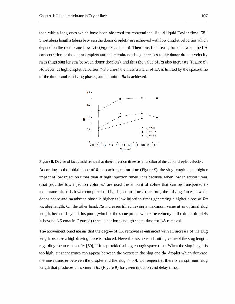
Chapter 4: Liquid membrane in Taylor flow 107
than within long ones which have been observed for conventional liquid-liquid Taylor flow [58].
Short slugs lengths (slugs between the donor droplets) are achieved with low droplet velocities which
depend on the membrane flow rate (Figures 5a and 6). Therefore, the driving force between the LA
concentration of the donor droplets and the membrane slugs increases as the donor droplet velocity
rises (high slug lengths between donor droplets), and thus the value of Ra also increases (Figure 8).
However, at high droplet velocities (>3.5 cm/s) the mass transfer of LA is limited by the space-time
of the donor and receiving phases, and a limited Ra is achieved.
Figure 8. Degree of lactic acid removal at three injection times as a function of the donor droplet velocity.
According to the initial slope of Ra at each injection time (Figure 9), the slug length has a higher
impact at low injection times than at high injection times. It is because, when low injection times
(that provides low injection volumes) are used the amount of solute that can be transported to
membrane phase is lower compared to high injection times, therefore, the driving force between
donor phase and membrane phase is higher at low injection times generating a higher slope of Ra
vs. slug length. On the other hand, Ra increases till achieving a maximum value at an optimal slug
length, because beyond this point (which is the same points where the velocity of the donor droplets
is beyond 3.5 cm/s in Figure 8) there is not long enough space-time for LA removal.
The abovementioned means that the degree of LA removal is enhanced with an increase of the slug
length because a high driving force is induced. Nevertheless, exist a limiting value of the slug length,
regarding the mass transfer [59], if it is provided a long enough space-time. When the slug length is
too high, stagnant zones can appear between the vortex in the slug and the droplet which decrease
the mass transfer between the droplet and the slug [7,60]. Consequently, there is an optimum slug
length that produces a maximum Ra (Figure 9) for given injection and delay times.

108 Applications of a liquid membrane in Taylor flow regime (LMTF) on separation processes and
design of fermentation hybrid systems
Figure 9. Effect of the slug length on the degree of lactic acid removal at different injection and delay times.
LA that is transported to the receiving phase as sodium lactate requires a lower space-time than LA
that is received as a free acid because of the instantaneous reaction and high driving force in the
former case [61]. Thus, Ra can also be enhanced if a low volume of receiving phase and a high
concentration of sodium hydroxide is used.
Susanti et al [48] study the LA removal using an extraction process in Taylor flow without back-
extraction. They found a 100% removal for a space-time of 90 s. In this study, a Ra of 1 is found for
a residence time of 80 s where extraction and back-extraction occur simultaneously. However,
between both studies there are differences in flow rates, channel length and diameter, organic phase
composition and concentration, thus this comparison has to be performed with caution.
4.1.5 Conclusions
The lactic acid removal in a liquid membrane in Taylor flow regime (LMTF) was measured at several
membrane flow rates, injection times of the dispersed phases and delay times. Also, the
hydrodynamic behavior of the LMTF was measured as a function of these parameters. LMTF
showed that is potentially useful for removal of LA acid from aqueous solutions.
The degree of LA removal (Ra) through the LMTF systems depends on the driving force of LA
concentrations between donor droplets and the membrane interface (D/M), and the space-time of the
phases within the channel. The LA removal among the phases is enhanced by low injection times
and high velocity of dispersed phases, which produces long space-times and high mass transfer
driving forces. Also, there is an optimal value of slug length for a given injection and delay times to
achieve the maximum value of Ra.

Chapter 4: Liquid membrane in Taylor flow 109
The LMTF is a potential technology for industrial applications that preserves the advantages of
conventional emulsion liquid membranes while overcomes the stability problems of emulsion
systems. LMTF can be integrated to other systems and enables the intensification of chemical and
fermentative processes
NOTATION
A Transversal section area of the channel (cm2)
CLA Lactic acid concentration (as free LA) at the
receiving phase (g/L)
CLA,aq Lactic acid concentration fed at aqueous donor phase
(g/L) *
,aqLAC
Lactic acid concentration in equilibria with
membrane phase at the side of the aqueous phase
(g/L)
CLA-NA Sodium lactate concentration at receiving phase
(g/L)
CLA,out Final lactic acid concentration at the outside of the
channel in the donor phase (g/L) *
,orgLAC
Lactic acid concentration in equilibria with
membrane phase at the side of the membrane phase
(g/L)
CLA-TiOA Concentration of the LA-TiOA complex at
membrane phase (g/L)
CR Sodium carbonate concentration in the receiving
phase (g/L)
LA Lactic acid
RLAstRRcomplex MWMWRCVLA
Maximum theoretical amount of lactic acid expected
by equation (7) at receiving phase (g)
DoutLAfree VCLA , Final amount of lactic acid in the donor phase (g)
LA-TiOA Complex produced in the reaction between the lactic
acid and the tri-iso-octylamine
LC Channel length (cm)
LMTF Liquid membrane in Taylor flow
MWLA Lactic acid molecular weight
MWR Sodium carbonate molecular weight
QD Flow rate of donor phase per injection (cm3/s)
QD,Tot Total flow rate when donor phase is injected (cm3/s)
QM Flow rate of membrane phase (cm3/s)
QR Flow rate of receiving phase per injection (cm3/s)
QR,Tot Total flow rate when receiving phase is injected
(cm3/s)
Ra Degree of lactic acid removed in the LMTF system
outLAaqLAinjDLA CCtQR ,,
Amount of lactic acid removed from donor phase (g)
Rst Stoichiometric ratio between lactic acid and sodium
carbonate in equation (7)
TiOA Tri-iso-octylamine

110 Applications of a liquid membrane in Taylor flow regime (LMTF) on separation processes and
design of fermentation hybrid systems
tdel Delay time between injection of the two dispersed
phases (s)
tinj Injection time of each dispersed phase (s)
UD Linear velocity of donor phase at injection point
(cm/s)
UR Linear velocity of receiving phase at the injection
point (cm/s)
VD Volume of donor phase per injection (cm3)
VR Volume of receiving phase per injection (cm3)
τD Space-time of the donor droplets (s)
τR Space-time of the receiving droplets (s)
4.1.6 References
[1] V.S. Kislik, Liquid Membranes Principles & Applications in Chemical Separation &
Wastewater Treatment, 1st ed., Elsevier B.V., Amsterdan, 2010.
[2] R.D. Noble, S.A. Stern, Membrane Separations Technology: Principles and Applications, 1st
ed., Elsevier, Amsterdan, 2003.
[3] N.M. Kocherginsky, Q. Yang, L. Seelam, Recent advances in supported liquid membrane
technology, Sep. Purif. Technol. 53 (2007) 171–177.
[4] A. Pérez de los Ríos, F.J. Hernández-Fernández, F. Tomás-Alonso, J.M. Palacios, G. Víllora,
Stability studies of supported liquid membranes based on ionic liquids: Effect of surrounding
phase nature, Desalination. 245 (2009) 776–782.
[5] T. Taha, Z.F. Cui, Hydrodynamics of slug flow inside capillaries, Chem. Eng. Sci. 59 (2004)
1181–1190.
[6] T.C. Thulasidas, M.A. Abraham, R.L. Cerro, Flow patterns in liquid slugs during bubble-
train flow inside capillaries, Chem. Eng. Sci. 52 (1997) 2947–2962.
[7] G.I. Taylor, Deposition of a viscous fluid on a plane surface, J. Fluid Mech. 9 (1961) 218.
[8] H.L. Goldsmith, S.G. Mason, The flow suspensions through tubes. II. Single large bubbles,
J. Coloid Sci. 18 (1963) 237–261.
[9] R. Gupta, S.S.Y. Leung, R. Manica, D.F. Fletcher, B.S. Haynes, Hydrodynamics of liquid–
liquid Taylor flow in microchannels, Chem. Eng. Sci. 92 (2013) 180–189.
[10] D. Tsaoulidis, P. Angeli, Effect of channel size on liquid-liquid plug flow in small channels,

Chapter 4: Liquid membrane in Taylor flow 111
AIChE J. 62 (2016) 315–324.
[11] A. Ufer, M. Mendorf, A. Ghaini, D.W. Agar, Liquid-Liquid Slug Flow Capillary
Microreactor, Chem. Eng. Technol. 34 (2011) 353–360.
[12] F.P. Bretherton, The motion of long bubbles in tubes, J. Fluid Mech. 10 (1961) 166–188.
[13] P. Aussillous, D. Quéré, Quick deposition of a fluid on the wall of a tube, Phys. Fluids. 12
(2000) 2367–2371.
[14] M. Sattari-Najafabadi, M. Nasr Esfahany, Z. Wu, B. Sundén, Hydrodynamics and mass
transfer in liquid-liquid non-circular microchannels: Comparison of two aspect ratios and
three junction structures, Chem. Eng. J. 322 (2017) 328–338.
[15] F. Kaske, S. Dick, S.A. Pajoohi, D.W. Agar, The influence of operating conditions on the
mass transfer performance of a micro capillary contactor with liquid–liquid slug flow, Chem.
Eng. Process. Process Intensif. 108 (2016) 10–16.
[16] O. Jafari, M. Rahimi, F.H. Kakavandi, Liquid-liquid extraction in twisted micromixers,
Chem. Eng. Process. Process Intensif. 101 (2016) 33–40.
[17] P. Plouffe, D.M. Roberge, A. Macchi, Liquid-liquid flow regimes and mass transfer in
various micro-reactors, Chem. Eng. J. 300 (2016) 9–19.
[18] J. Fontalvo, A.D. Pérez, Membrana Líquida y proceso para realizarlo, Colombian pending
patent, Rad. 15-131023.
[19] A.D. Pérez, Desarrollo y evaluación de un sistema de membrana líquida en flujo de Taylor
para la remoción de ácido láctico, Master dissertation, Universidad Nacional de Colombia,
2014.
[20] M. Marinova, J. Albet, J. Molinier, G. Kyuchoukov, Specific influence of the modifier (1-
Decanol) on the extraction of tartaric acid by different extractants, Ind. Eng. Chem. Res. 44
(2005) 6534–6538.
[21] R. Canari, A.M. Eyal, Extraction of carboxylic acids by amine-based extractants: Apparent
extractant basicity according to the pH of half-neutralization, Ind. Eng. Chem. Res. 42 (2003)
1285–1292.
[22] Z. Gu, B.A. Glatz, C.E. Glatz, Propionic acid production by extractive fermentation. I.
Solvent considerations, Biotechnol. Bioeng. 57 (1998) 454–461.

112 Applications of a liquid membrane in Taylor flow regime (LMTF) on separation processes and
design of fermentation hybrid systems
[23] A.M. Eyal, R. Canari, pH Dependence of Carboxylic and Mineral Acid Extraction by Amine-
Based Extractants: Effects of pKa, Amine Basicity, and Diluent Properties, Ind. Eng. Chem.
Res. 34 (1995) 1789–1798.
[24] H. Ziegenfuß, G. Maurer, Distribution of acetic acid between water and organic solutions of
tri-n-octylamine, Fluid Phase Equilib. 102 (1994) 211–255.
[25] S.T. Yang, S.A. White, S.T. Hsu, Extraction of Carboxylic Acids with Tertiary and
Quaternary Amines: Effect of pH, Ind. Eng. Chem. Res. 30 (1991) 1335–1342.
[26] S. Pandey, S. Kumar, Reactive Extraction of Gallic Acid Using Aminic and Phosphoric
Extractants Dissolved in Different Diluents: Effect of Solvent’s Polarity and Column Design,
Ind. Eng. Chem. Res. 57 (2018) 2976–2987.
[27] G. Malmary, J. Albet, A. Putranto, H. Hanine, J. Molinier, Measurement of partition
coefficients of carboxylic acids between water and triisooctylamine dissolved in various
diluents, J. Chem. Eng. Data. 43 (1998) 849–851.
[28] D.H. Han, W.H. Hong, Water-Enhanced Solubilities of Lactic Acid in Reactive Extraction
Using Trioctylamine/Various Active Diluents Systems, Sep. Sci. Technol. 33 (1998) 271–
281.
[29] D. Yankov, J. Molinier, J. Albet, G. Malmary, G. Kyuchoukov, Lactic acid extraction from
aqueous solutions with tri-n-octylamine dissolved in decanol and dodecane, Biochem. Eng.
J. 21 (2004) 63–71.
[30] G. Kyuchoukov, A. Labbaci, J. Albet, J. Molinier, Simultaneous Influence of Active and
“Inert” Diluents on the Extraction of Lactic Acid by Means of Tri- n -octylamine (TOA) and
Tri- iso -octylamine (TIOA), Ind. Eng. Chem. Res. 45 (2006) 503–510.
[31] W. Qin, Z. Li, Y. Dai, Extraction of Monocarboxylic Acids with Trioctylamine: Equilibria
and Correlation of Apparent Reactive Equilibrium Constant, Ind. Eng. Chem. Res. 42 (2003)
6196–6204.
[32] A.D. Pérez, S. Rodríguez-Barona, J. Fontalvo, Liquid–Liquid Equilibria for Trioctylamine/1-
Dodecanol/Lactic Acid/Water System at 306.1, 310.1 and 316.1 K: Experimental Data and
Prediction, J. Chem. Eng. Data. 61 (2016) 2269–2276.
[33] M. Hossain, Mass Transfer Investigation of Organic Acid Exatraction with Trioctylamine

Chapter 4: Liquid membrane in Taylor flow 113
and Aliquat 336 Dissolved in Various Solvents, in: Mass Transf. Multiph. Syst. Its Appl.,
InTech, 2011: pp. 367–388.
[34] K.L. Wasewar, A.A. Yawalkar, J.A. Moulijn, V.G. Pangarkar, Fermentation of Glucose to
Lactic Acid Coupled with Reactive Extraction: A Review, Ind. Eng. Chem. Res. 43 (2004)
5969–5982.
[35] D. Yankov, J. Molinier, G. Kyuchoukov, J. Albet, G. Malmary, Improvement of the Lactic
Acid Extraction . Extraction From Aqueous Solutions and Simulated Fermentation Broth by
Means of Mixed Extractant and TOA , Partially Loaded with HCl, Chem. Biochem. Eng. Q.
19 (2005) 17–24.
[36] J.A. Tamada, A.S. Kertes, C.J. King, Extraction of carboxylic acids with amine extractants.
1. Equilibria and law of mass action modeling, Ind. Eng. Chem. Res. 29 (1990) 1319–1326.
[37] B. Choudhury, T. Swaminathan, Lactic acid extraction with trioctyl amine, Bioprocess Eng.
19 (1998) 317.
[38] C.S. López-Garzón, A.J.J. Straathof, Recovery of carboxylic acids produced by fermentation,
Biotechnol. Adv. 32 (2014) 873–904.
[39] A. Krzyzaniak, M. Leeman, F. Vossebeld, T.J. Visser, B. Schuur, A.B. De Haan, Novel
extractants for the recovery of fermentation derived lactic acid, Sep. Purif. Technol. 111
(2013) 82–89.
[40] F.S. Oliveira, J.M.M. Araújo, R. Ferreira, L.P.N. Rebelo, I.M. Marrucho, Extraction of l-
lactic, l-malic, and succinic acids using phosphonium-based ionic liquids, Sep. Purif.
Technol. 85 (2012) 137–146.
[41] J. Marták, Š. Schlosser, Extraction of lactic acid by phosphonium ionic liquids, Sep. Purif.
Technol. 57 (2007) 483–494.
[42] A. Krzyzaniak, B. Schuur, A.B. De Haan, Equilibrium studies on lactic acid extraction with
N,N-didodecylpyridin-4-amine (DDAP) extractant, Chem. Eng. Sci. 109 (2014) 236–243.
[43] A.D. Pérez, S. Rodríguez-Barona, J. Fontalvo, Molecular toxicity of potential liquid
membranes for lactic acid removal from fermentation broths using Lactobacillus casei ATCC
393, Dyna. 85 (2018) 360–366.
[44] A.D. Pérez, V.M. Gómez, S. Rodríguez-Barona, J. Fontalvo, Liquid-liquid Equilibrium and

114 Applications of a liquid membrane in Taylor flow regime (LMTF) on separation processes and
design of fermentation hybrid systems
Molecular Toxicity of Active and Inert diluents of the Organic Mixture Tri-iso-
octylamine/Dodecanol/Dodecane as Potential Membrane Phase for Lactic Acid Removal, J.
Chem. Eng. Data. submited (2019).
[45] A.D. Pérez, S. Rodríguez-Barona, J. Fontalvo, Liquid–Liquid Equilibria of Lactic
Acid/Water Solutions in Tri-iso-octylamine/Dodecane/1-Dodecanol at 306.1, 310.1, and
316.1 K. Experimental Data and Prediction, J. Chem. Eng. Data. 64 (2019) 603-610.
[46] M. Matsumoto, T. Takagi, K. Kondo, Separation of lactic acid using polymeric membrane
containing a mobile carrier, J. Ferment. Bioeng. 85 (1998) 483–487.
[47] D. Yankov, J. Molinier, J. Albet, G. Malmary, G. Kyuchoukov, Lactic acid extraction from
aqueous solutions with tri-n-octylamine dissolved in decanol and dodecane, Biochem. Eng.
J. 21 (2004) 63–71.
[48] Susanti, J.G.M. Winkelman, B. Schuur, H.J. Heeres, J. Yue, Lactic Acid Extraction and Mass
Transfer Characteristics in Slug Flow Capillary Microreactors, Ind. Eng. Chem. Res. 55
(2016) 4691–4702.
[49] G. Chronopoulos, A. Bekatorou, E. Bezirtzoglou, A. Kaliafas, A.A. Koutinas, R. Marchant,
I.M. Banat, Lactic acid fermentation by Lactobacillus casei in free cell form and immobilised
on gluten pellets, Biotechnol. Lett. 24 (2002) 1233–1236.
[50] O. Sejong, R. Sungsue, S. Jaehun, K. Sangkyo, B. Yungjin, Optimizing conditions for the
growth of Lactobacillus casei YIT 9018 in Tryptone-Yeast Extarct- Glucose Medium by
using response surface methodology, Appl. Environ. Microbiol. 61 (1995) 3809–3814.
[51] P.S. Panesar, J.F. Kennedy, C.J. Knill, M. Kosseva, Production of L(+) Lactic Acid using
Lactobacillus casei from Whey, Brazilian Arch. Biol. Technol. 53 (2010) 219–226.
[52] A.D. Pérez, B. Van der Bruggen, J. Fontalvo, Study of overall mass transfer coefficients in a
liquid membrane in Taylor flow regime: Calculation and correlation, Chem. Eng. Process. -
Process Intensif. 134 (2018) 20–27.
[53] G.F. Teletzke, H.T. Davis, L.E. Scriven, Wetting hydrodynamics, Rev. Phys. Appliquée. 23
(1988) 989–1007.
[54] H. V. Nickens, D.W. Yannitell, The effects of surface tension and viscosity on the rise
velocity of a large gas bubble in a closed, vertical liquid-filled tube, Int. J. Multiph. Flow. 13

Chapter 4: Liquid membrane in Taylor flow 115
(1987) 57–69.
[55] J.D. Tice, A.D. Lyon, R.F. Ismagilov, Effects of viscosity on droplet formation and mixing
in microfluidic channels, Anal. Chim. Acta. 507 (2004) 73–77.
[56] M.N. Kashid, D.W. Agar, S. Turek, CFD modelling of mass transfer with and without
chemical reaction in the liquid-liquid slug flow microreactor, Chem. Eng. Sci. 62 (2007)
5102–5109.
[57] N. Aoki, S. Tanigawa, K. Mae, A new index for precise design and advanced operation of
mass transfer in slug flow, Chem. Eng. J. 167 (2011) 651–656.
[58] C. Butler, E. Cid, A.M. Billet, Modelling of mass transfer in Taylor flow: Investigation with
the PLIF-I technique, Chem. Eng. Res. Des. 115 (2016) 292–302.
[59] M. Mendorf, D.W. Agar, Scale-up of Capillary Extraction Equipment, Chemie Ing. Tech. 83
(2011) 1120–1124.
[60] J. Fontalvo, M. a. G. Vorstman, J.G. Wijers, J.T.F. Keurentjes, Heat supply and reduction of
polarization effects in pervaporation by two-phase feed, J. Memb. Sci. 279 (2006) 156–164.
[61] R. Juang, S. Lee, R. Shiau, Mass-transfer modeling of permeation of lactic acid across amine-
mediated supported liquid membranes, J. Memb. Sci. 137 (1997) 231–239.

116 Applications of a liquid membrane in Taylor flow regime (LMTF) on separation processes and
design of fermentation hybrid systems
4.2 Study of overall mass transfer coefficients in a liquid
membrane in Taylor flow regime: Calculation and
correlation6
Abstract
The use of a liquid membrane in Taylor flow regime is a recent technology, which extends and
generalizes the definition of a membrane. It has been developed and tested for lactic acid removal.
A challenge in understanding the technology is that the values of the overall volumetric mass transfer
coefficients are not known, and it is unclear how they are related with the operational conditions. In
this work, the overall volumetric mass transfer for the liquid membrane in Taylor flow was calculated
from experimental results and three empirical models, two of which are from literature and one was
developed in this work based on dimensional analysis. From combination of experimental results
and the developed models the main variables (operational conditions) of the liquid membrane in
Taylor flow that have a strong influence on the overall volumetric mass transfer coefficients (in the
donor and in the membrane phase) were defined. The relative velocity results as the variable that has
the largest influence on the performance of this new liquid membrane technology.
6 This section has been published in: Chemical Engineering & Processing: Process Intensification 134
(2018) 20–27: Alan D. Perez, Bart Van der Bruggen, Javier Fontalvo

Chapter 4: Liquid membrane in Taylor flow 117
4.2.1 Introduction
Liquid membrane in Taylor flow regime (LMTF) is a recently developed separation technology [1,2]
that uses the Taylor flow regime as a contact media among the phases of a liquid membrane taking
advantage of the enhanced mass transfer of this type of two-phase flow (extended to a three phases
system). In the LMTF the solute is transported from the donor drops to the receiving drops through
the membrane, which is the continuous phase [1,2].
Nowadays several studies of mass transfer in liquid-liquid systems have been developed. One of the
most applied two-phase flow regimes is Taylor flow (also denoted as slug flow, plug flow or
segmented flow). Taylor flow enhances mass and heat transfer even in laminar conditions [3,4] due
to the presence of a continuous phase film that separates the droplets from the channel wall [5],
internal recirculation within the slug and the droplets that are induced by wall shear [6–8], which
enhances diffusive penetration [9] and renews the interfaces [5], in addition to the high specific
interfacial areas in this kind of two-phase flow [7,8]. Understanding the enhanced potential for mass
transfer of Taylor flow, several studies have focused on the development of new microdevices that
enhance the mass transfer, such as micromixers [10–12], twisted channels [13], caterpillar channels
[14], microstructured reactors [15–17], while others were focused on the development and testing of
devices for the separation of the involved phases in these systems [4,5,12,17–20].
Most of these studies considered the overall mass transfer coefficient (OVMTC) in liquid-liquid flow
regimes in order to quantify the mass transfer. The overall mass transfer coefficient is a parameter
or index to compare how much the mass transfer has been increased using a given two-phase flow
regime, among the types of microdevices, and depending on the kind of operation used in these
systems. OVMTC values have been calculated from experimental results through the mass balance
from the drop or the continuous phase [15]. Extraction of phenol in dodecane to water phase was
studied through OVMTC values calculated from the temporal change of the concentration of
extracted phenol in the water phase using slug flow, testing the influence of expansions and
contractions of the microchannel on mass transfer [21]. The same system was evaluated in circular
and semicircular microchannels through the OVMTC achieved from the mass balance for the change
of concentration of phenol [22]. The OVMTC was calculated from the mass flux through the
interface droplet-continuous phases in square microchannels for the system water/acetone/toluene
with acetone as solute in slug flow [4]. The same system was evaluated in different types of
microchannels and at several two-phase flows including slug flow [14]. The microfluidic extraction
of the systems water/phenol/n-hexane, water/acetone/toluene, water/succinic acid/n-octanol and

118 Applications of a liquid membrane in Taylor flow regime (LMTF) on separation processes and
design of fermentation hybrid systems
water/succinic acid/n-butanol was tested using the OVMTC [23]. Several operational conditions
were tested for the systems water/acetone/toluene and water/acetic acid/kerosene in microcapillary
contactor using Taylor flow [19]. Extraction of acetone in the system n-butyl acetate/acetone/water
was tested using slug flow in different microstructured devices [17]. The removal of some organic
acids was tested using OVMTC values in systems such as water/succinic acid/n-butanol from CFD
simulations using slug flow [24], aqueous sodium hydroxide/acetic acid/n-hexane for non-circular
microchannels with three junctions [11], aqueous sodium hydroxide/tricloroacetic acid/n-hexane
using slug flow in circular microchannels at several surfactant concentrations (sodium dodecyl
sulfate) [25], aqueous lactic acid/tri-octylamine/n-octanol in slug flow within capillary microreactors
(using the mean concentration difference as driving force for the OVMTC) [20], water/succinic
acid/n-butanol at different types of microchannels (using the mean concentration difference for the
OVMTC calculations) [12], water/toluene/tricoloracetic acid and water/n-hexane/tricoloracetic acid
in rectangular microchannels at slug and parallel flows [26], water/succinic acid/1-butanol at several
two-phase flow regimes including slug flow using corning microreactors [27], and the system
kerosene/acetic acid/water through slug flow in a microstructured reactor [16]. Various
microreactors and micromixers were tested using the system n-butanol/toluene/4-nitrophenyl acetate
for several liquid-liquid flow regimes [28]. Slug and drop flow mass transfer were tested for the
systems aqueous sodium hydroxide/n-butanol/4-nitrophenyl acetate and aqueous sodium
hydroxide/toluene/4-nitrophenyl acetate in different microreactors [29]. Extraction of copper ions
from nitric acid using a tributylphosphate and ionic liquids mixture was evaluated at different
channel size [5]. Extraction of copper was also tested with di-(2-ethylhexyl)phosphoric
acid/kerosene mixture in twisted micromixers [13]. The extraction of NBF ester from n-butyl
formate to an aqueous solution of sodium hydroxide was carried out using a microreactor and it was
tested using OVMTC with the logarithmic-mean of concentrations as driving force of transport of
NBF [30].
Additionally, some studies have used or developed empirical correlations in order to predict the
overall volumetric mass transfer coefficient. M. Kashid et al. [16] proposed a correlation for mass
transfer in microstructured reactors using dimensional analyses through the Buckingham Pi method
and applied this method to the system kerosene/acetic acid/water where the predicted values were in
a good agreement with the experimental values (with R2 of 0.95). The aforementioned model was
used in other work [15] in order to predict the values of the OVMTC in liquid-liquid systems using
microstructured reactors. Di Miceli Raimondi et al. [31] developed numerical simulations of mass
transfer in slug flow; from these results they calculated the OVMTC and compared it with the values
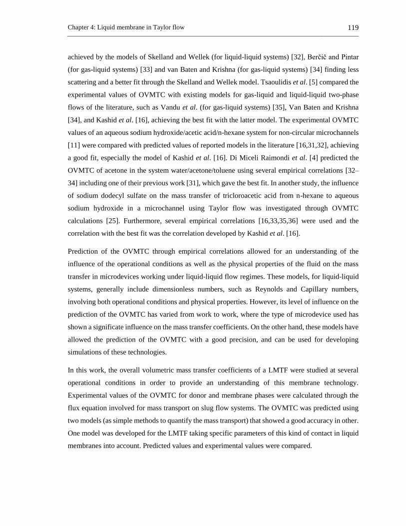
Chapter 4: Liquid membrane in Taylor flow 119
achieved by the models of Skelland and Wellek (for liquid-liquid systems) [32], Berčič and Pintar
(for gas-liquid systems) [33] and van Baten and Krishna (for gas-liquid systems) [34] finding less
scattering and a better fit through the Skelland and Wellek model. Tsaoulidis et al. [5] compared the
experimental values of OVMTC with existing models for gas-liquid and liquid-liquid two-phase
flows of the literature, such as Vandu et al. (for gas-liquid systems) [35], Van Baten and Krishna
[34], and Kashid et al. [16], achieving the best fit with the latter model. The experimental OVMTC
values of an aqueous sodium hydroxide/acetic acid/n-hexane system for non-circular microchannels
[11] were compared with predicted values of reported models in the literature [16,31,32], achieving
a good fit, especially the model of Kashid et al. [16]. Di Miceli Raimondi et al. [4] predicted the
OVMTC of acetone in the system water/acetone/toluene using several empirical correlations [32–
34] including one of their previous work [31], which gave the best fit. In another study, the influence
of sodium dodecyl sulfate on the mass transfer of tricloroacetic acid from n-hexane to aqueous
sodium hydroxide in a microchannel using Taylor flow was investigated through OVMTC
calculations [25]. Furthermore, several empirical correlations [16,33,35,36] were used and the
correlation with the best fit was the correlation developed by Kashid et al. [16].
Prediction of the OVMTC through empirical correlations allowed for an understanding of the
influence of the operational conditions as well as the physical properties of the fluid on the mass
transfer in microdevices working under liquid-liquid flow regimes. These models, for liquid-liquid
systems, generally include dimensionless numbers, such as Reynolds and Capillary numbers,
involving both operational conditions and physical properties. However, its level of influence on the
prediction of the OVMTC has varied from work to work, where the type of microdevice used has
shown a significate influence on the mass transfer coefficients. On the other hand, these models have
allowed the prediction of the OVMTC with a good precision, and can be used for developing
simulations of these technologies.
In this work, the overall volumetric mass transfer coefficients of a LMTF were studied at several
operational conditions in order to provide an understanding of this membrane technology.
Experimental values of the OVMTC for donor and membrane phases were calculated through the
flux equation involved for mass transport on slug flow systems. The OVMTC was predicted using
two models (as simple methods to quantify the mass transport) that showed a good accuracy in other.
One model was developed for the LMTF taking specific parameters of this kind of contact in liquid
membranes into account. Predicted values and experimental values were compared.
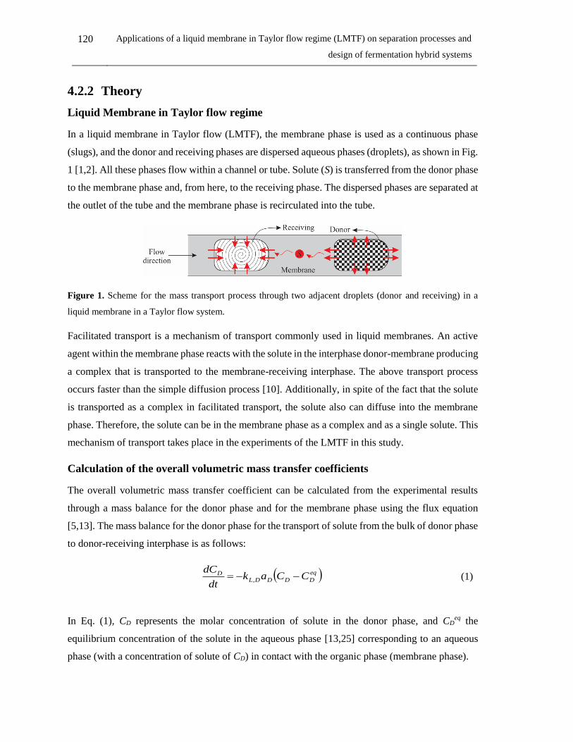
120 Applications of a liquid membrane in Taylor flow regime (LMTF) on separation processes and
design of fermentation hybrid systems
4.2.2 Theory
Liquid Membrane in Taylor flow regime
In a liquid membrane in Taylor flow (LMTF), the membrane phase is used as a continuous phase
(slugs), and the donor and receiving phases are dispersed aqueous phases (droplets), as shown in Fig.
1 [1,2]. All these phases flow within a channel or tube. Solute (S) is transferred from the donor phase
to the membrane phase and, from here, to the receiving phase. The dispersed phases are separated at
the outlet of the tube and the membrane phase is recirculated into the tube.
Figure 1. Scheme for the mass transport process through two adjacent droplets (donor and receiving) in a
liquid membrane in a Taylor flow system.
Facilitated transport is a mechanism of transport commonly used in liquid membranes. An active
agent within the membrane phase reacts with the solute in the interphase donor-membrane producing
a complex that is transported to the membrane-receiving interphase. The above transport process
occurs faster than the simple diffusion process [10]. Additionally, in spite of the fact that the solute
is transported as a complex in facilitated transport, the solute also can diffuse into the membrane
phase. Therefore, the solute can be in the membrane phase as a complex and as a single solute. This
mechanism of transport takes place in the experiments of the LMTF in this study.
Calculation of the overall volumetric mass transfer coefficients
The overall volumetric mass transfer coefficient can be calculated from the experimental results
through a mass balance for the donor phase and for the membrane phase using the flux equation
[5,13]. The mass balance for the donor phase for the transport of solute from the bulk of donor phase
to donor-receiving interphase is as follows:
eq
DDDDLD CCak
dt
dC ,
(1)
In Eq. (1), CD represents the molar concentration of solute in the donor phase, and CDeq the
equilibrium concentration of the solute in the aqueous phase [13,25] corresponding to an aqueous
phase (with a concentration of solute of CD) in contact with the organic phase (membrane phase).

Chapter 4: Liquid membrane in Taylor flow 121
Integrating Eq. (1) and taking into account the distribution coefficient (K) of the liquid-liquid
equilibrium (given in Eq. (2)), the overall volumetric mass transfer can be calculated as shown in
Eq. (3).
eq
D
eq
M CCK (2)
DDDLeq
MDD
eq
MD akKCC
KCtC
,
0ln (3)
The symbol t0 represents time at the injection point of the donor phase (0 s) and τ represents the
average residence time.
The overall volumetric mass transfer coefficient through the membrane phase, from the bulk of the
membrane phase to the membrane-receiving interphase was calculated from a mass balance with the
flux equation in steady state, where the flux from donor to membrane phase is the same flux than the
flux from the membrane to receiving phase ( ssJ ):
M
eq
RTMRMLss VCCakJ ,, (4)
Where V,M is the volume in the membrane phase within the channel, CM,T is the total solute
concentration in the membrane phase (free solute and in the complex form) in steady state, calculated
from a mass balance of solute between donor and membrane phases (from t = 0 till the steady state
is reached for every single experiment). The solute concentration in the receiving phase is zero (𝐶𝑅𝑒𝑞
= 0) because in the receiving phase there is an active agent that reacts instantaneously with the solute
of the membrane phase. Therefore, the final equation for the overall volumetric mass transfer
coefficient for the membrane phase is:
MTM
ss
RMLVC
Jak
,
, (5)
The used parameters for Eqs. (1)-(5) are defined with their respective units in the nomenclature table.
Models for the overall mass transfer coefficient prediction
The model proposed by Di Miceli Raimondi et al. [4,31] and used by Sattari-Najafabadi et al. [11]
for mass transfer in extraction systems in Taylor flow was adapted in order to be applied for
122 Applications of a liquid membrane in Taylor flow regime (LMTF) on separation processes and
design of fermentation hybrid systems
prediction of the overall volumetric mass transfer coefficients of a liquid membrane in Taylor flow
regime. Eqs. (6)-(7) show the abovementioned model for prediction of the overall volumetric mass
transfer coefficient, for both the donor and membrane phase.
54
3
2
,
,1,
dD
DT
DT
UCD
D
dD
DDDL
d
dUdU
V
V
d
aak (6)
'5
'4
'3
'2
,
,
'
1,
dR
RT
RT
UCR
R
dR
RRML
d
dUdU
V
V
d
aak (7)
A second model was adapted from the model used by Kashid et al. [15,16] in liquid-liquid extraction
process using microreactors. This adapted model is shown in Eqs. (8)-(9) for the overall volumetric
mass transfer coefficient of the donor and membrane phases.
4
32
,,1, Re
L
dCaak DmixDmixDDDL
(8)
'4
'3
'2
,,
'
1, Re
L
dCaak RmixRmixRRML
(9)
where L is the channel length and λ and λ’ are fitted parameters of the model. The dimensionless
numbers, Capillary number (Ca) and, Reynolds number (Re) were calculated for the respective phase
(donor or receiving) at weighted physical properties according to the flow rates [15,16].
DmixDT
Dmix
UCa
,,
,
;
RmixRT
Rmix
UCa
,,
,
(10)
Dmix
DTDmix
Dmix
dU
,
,,
,Re
;
Rmix
RTRmix
Rmix
dU
,
,,
,Re
(11)
DM
DD
DM
MMDmix
Q
Q ,
;
RM
RD
RM
MMRmix
Q
Q ,
(12)
DM
DD
DM
MMDmix
Q
Q ,
;
RM
RD
RM
MMRmix
Q
Q ,
(13)
Chapter 4: Liquid membrane in Taylor flow 123
where µ, ρ and Q are the viscosity, density and flow rate, respectively, of the donor (D), receiving
(R) or membrane phase (M).
Additionally, a third model was developed in this work, knowing that the overall volumetric mass
transfer coefficient is function of the following variables: channel length, slug length, total velocity
of the dispersed (donor or receiving) and membrane phases, injection time and channel diameter. In
addition, it is function of physical properties: viscosity, density and interfacial tension (Eqs. (14) and
(15)).
,,,,,,,, ,,,,, DmixDmixinjMTDTslugDDL dtUULLfak (14)
,,,,,,,, ,,,,, RmixRmixinjMTRTslugRML dtUULLfak (15)
Using dimensional analysis through the Rayleigh method [37] the following equations for the overall
volumetric mass transfer coefficients were derived:
76
5
432 ,
,,
,
1, 1Re
d
L
d
L
d
tUWCa
d
Uak
slug
injDT
DDmixDmix
DT
DDL
(16)
'7
'6
'5
'4
'3
'2 ,
,,
,'
1, 1Re
d
L
d
L
d
tUWCa
d
Uak
slug
injRT
RRmixRmix
RT
RML
(17)
where tinj, is the injection time of the respective dispersed phase, α and α’ are the fitted parameters.
This model includes the dimensionless number relative velocity (W) that was used by Taylor [38] to
propose an empirical relationship between this dimensionless number and the capillary number in
which the flow patterns of slug flow could be predicted.
The dimensionless relative velocity is calculated as follows:
DT
MTDT
DU
UUW
,
,, ;
RT
MTRT
RU
UUW
,
,, (18)

124 Applications of a liquid membrane in Taylor flow regime (LMTF) on separation processes and
design of fermentation hybrid systems
4.2.3 Materials and methods
Materials
Tri-iso-octylamine (TiOA- assay 95%), n-dodecane (assay 99%), 1-dodecanol (assay 98%), and
sodium carbonate (assay 99.5%) were supplied by Merck Millipore. L(+)-lactic acid was supplied
by Panreac Química S.A.U. (assay 88.0-92.0%). The purity of lactic acid was assessed by titration
with sodium hydroxide of Carlo Erba (assay ≥ 97.0%) using a Metrohm automatic titrator (702 SM
Titrino, 703 TI Stand). A stock solution of lactic acid (150 g/L) were heated at 90 °C under total
reflux between 8-10 hours for dimer hydrolysis [39,40] and subsequently, the lactic acid
concentration was measured by titration. Type I water was used for all aqueous solutions
(Barnstead™ Nanopure™).
Experiments of the liquid membrane in Taylor flow regime
Figure 2. Experimental setup used in the LA removal with a LMTF.

Chapter 4: Liquid membrane in Taylor flow 125
The LMTF was tested for lactic acid (LA) removal. The membrane phase was a mixture of Tri-iso-
octylamine, dodecanol and dodecane at 10, 40 and 50 vol%, respectively. The donor phase was an
aqueous solution of LA at 10 g/L prepared from the stock solution. The receiving phase was an
aqueous solution of sodium carbonate at 2.5 g/L.
In this system, TiOA is a carrier that reacts with the LA from the donor phase in order to produce an
LA-TiOA complex. This LA-TiOA complex is transported to the membrane-receiving interphase
where an instantaneous acid-base reaction is carried out between the sodium carbonate and the LA
of the LA-TiOA complex. Additionally, a small amount of free LA is solubilized in the membrane
phase that also reacts with the sodium carbonate in the membrane-receiving interface as well.
Table 1. Experimental conditions tested for lactic acid removal with a LMTF system.
Membrane
flow rate, QM
(cm3/s)
Donor
flow rate,
QD (cm3/s)
Receiving
flow rate, QR
(cm3/s)
Injection
time, tinj
(s)
Delay
time,
tdel (s)
0.0750 0.0333 0.0193 6 6
0.0750 0.0333 0.0193 12 12
0.0750 0.0333 0.0193 16 16
0.1083 0.0333 0.0173 6 6
0.1083 0.0333 0.0173 12 12
0.1083 0.0333 0.0173 16 16
0.1417 0.0333 0.0122 6 6
0.1417 0.0333 0.0122 12 12
0.1417 0.0333 0.0122 16 16
0.1650 0.0333 0.0118 6 6
0.1650 0.0333 0.0118 12 12
In the experiments a transparent polyurethane circular channel (tubing) of 2.5 mm of inner diameter
and 348.8 cm of length, coiled in a vertical length of 45 cm was used. For the flow of the membrane
phase a HPLC pump (Waters 501) was used. The injection of donor phase was carried out through
a syringe pump (Cole-Parmer® Touch Screen Infuse/Withdraw) and for the receiving phase was
used a gear pump (Ismatec, Reglo-z) with a pump-head (Ismatec Z-186, at a fixed flow rate of 5%)
coupled to a solenoid valve (STNC® - DC 24V). The injection time of the donor phase was
programmed in the syringe pump. The receiving phase injection was controlled by the open-close
times of the solenoid valve Through a Arduino Mega. For separation of the donor and receiving
droplets, a settler with two separate compartments (Figure 2), one for each aqueous phase, was used.
No entrainment is possible between the two compartments. Due to the aqueous phases are already
126 Applications of a liquid membrane in Taylor flow regime (LMTF) on separation processes and
design of fermentation hybrid systems
separated in droplets from the organic phase, the residence time for separation in each compartment
is short and lower than 5 s. Donor and receiving phases are injected at specific times and between
injections, there is a delay time (6 – 16 s) where no aqueous phase injection takes place. For a given
injection time, for a train of droplets, of donor or receiving phase, and the residence time (85 – 160
s), it was possible to know the time where a given phase (donor or receiving) arrived at the top of
the channel. Consequently, the train of droplets at the top of the channel is fed to the corresponding
settler using a flexible tubing. The time required for the flexible tubing to shift to the corresponding
compartment is lower (1 s) than the delay time. The organic phase split from each compartment was
recycled to the inlet of the channel.
Several flow rates of the membrane phase, and of the dispersed phases (donor and receiving) were
tested at several injection and delay times. The delay time is the elapsed time from the end of the
injection of the donor phase until starts the injection of the receiving phase. The tested experimental
conditions are shown in Table 1. In each injection of the respective dispersed phase, a train of
droplets is formed, as shown in Fig. 2.
During the constant flow of the membrane phase within the channel, each injection cycle follows the
following four steps: First, the donor phase is injected during tinj. Then the injection of the donor
phase is stopped and the delay time (tdel) elapses. Afterwards, the receiving phase start to inject
during tinj, and in the fourth step, the receiving phase injection is stopped and the delay time elapses
again. The aforementioned cycle is repeated along the experiment time (between 30 and 50 min). In
each injection of the donor or receiving phase, a train of droplets of the respective phase is formed
(Fig. 3). The flow rate of the donor phase was kept at the same value, thus the variation of the injected
volume of the donor phase is only due to the injection time. For the receiving phase, the flow rate
was kept 5%, however, the injected volume of this phase depends on the injection time and the flow
rate of the membrane phase. The same value of the injection time was used for the delay time for
each experiment.
Two kinds of slug are formed during the process as shown in Fig. 3 and each one has its respective
length. There is a slug length between the back cap of the last droplet of a train of droplets of the
donor phase and the front cap of the first droplet of the subsequent train of droplets of the receiving
phase. Another slug is located into the train of droplets of the same phase, and its length is given
between the back cap of a droplet and the front cap of the subsequent droplet.

Chapter 4: Liquid membrane in Taylor flow 127
Figure 3. Scheme of the slug lengths that are formed in the LMTF system.
For each experiment, the LA concentration was measured from the samples of the donor and
receiving phases that were collected in the corresponding container of the settler. HPLC method was
used for LA concentration measurements [2]. These samples were taken at long the time of the
experiment until the concentration of LA in the aqueous phases was constant (where the steady state
is achieved), at that time the experiment was stopped. Every experiment was carried out at 37 °C.
The system reaches a steady state operation. The steady state is reached when the amount of LA
removed from the donor phase equals the amount of LA that is captured by the receiving phase. So,
in steady state, the LA concentration in the organic phase is relatively low but far from equilibrium.
The amount of LA in the organic phase fed to the channel, which is reached at steady state, depends
on the specific operating conditions. LA concentration was measured by HPLC from samples of the
aqueous phases in each compartment as a function of time till the concentrations were constant and
the steady state was reached. HPLC chromatograms for samples coming from the receiving phase
present a small pick due to the salt. This small pick is not shown for samples coming from the donor
phase
Physical properties calculation
Density and the viscosity of the fed donor and receiving phases were measured experimentally at 37
°C using a pycnometer of 5 mL (Vilab) and an Ubbelohde viscometer (Cannon), respectively.
Physical properties at 37 °C of tri-iso-octylamine [41], dodecane [42] and dodecanol [43] were taken
from literature. The membrane phase density and viscosity were calculated as a function of the
volumetric fraction of each substance:
DOHDodTiOAM 4.05.01.0 (19)
DOHDodTiOAM 4.05.01.0 (20)
128 Applications of a liquid membrane in Taylor flow regime (LMTF) on separation processes and
design of fermentation hybrid systems
The interfacial tension was calculated as average from the literature values of dodecane-water [44]
and dodecanol-water [45] systems at 37 °C, because dodecanol and dodecane are the substance of
the highest concentration in the membrane phase and lactic acid is a low concentration in the aqueous
phase.
Fit of the overall volumetric mass transfer coefficient from the models
Fitting of the aforementioned models was achieved using Matlab® (with globalsearch function)
through the average absolute relative deviation (AARD) showed in Eq. (21).
N
i iL
icalcLiL
ak
akak
NAARD
1 exp,
,exp,1 (21)
where N is the number of data (experiments) and i is the i-th experiment. A Matlab® script was
developed using the globalsearch function to minimize the equation (21). The experimental values
of the OVMTC were achieved from equations (3) and (5), for solute transport from the bulk of the
donor phase to the donor-membrane interphase and for solute transport from the bulk of membrane
phase to the membrane-receiving interphase, respectively. The calculated values were achieved from
equations (6), (8) and (16) for the solute transport from the bulk of the donor phase to the donor-
membrane interphase and from equations (7), (9) and (17) for solute transport from the bulk of
membrane phase to the membrane-receiving interphase depending of the model used (one of the two
taken from the literature or the developed model in this work).
4.2.4 Results and discussion
Calculation of experimental overall volumetric mass transfer coefficients
The overall volumetric mass transfer coefficients were calculated from Eqs. (3) and (5), in the donor
phase and in the membrane phase, respectively. The velocity of each phase was calculated from the
tested volumetric flow rates. In Fig. 4 the influence of the droplet velocity on the overall volumetric
mass transfer coefficient (OVMTC) is shown. For both overall volumetric mass transfer coefficients
in Fig. 4, the higher the droplet velocity (donor or receiving), the higher the OVMTC. A high velocity
of the droplet could decrease the mass transfer resistance that is due to the viscosity (shear stress) of
the fluids. Furthermore, the higher the droplet velocity, the higher the interfacial velocity of the
droplets, which could provide a higher mixing velocity (vortices of higher velocity) that
consequently increases the mass transfer. On the other hand, the liquid surrounding the donor droplet
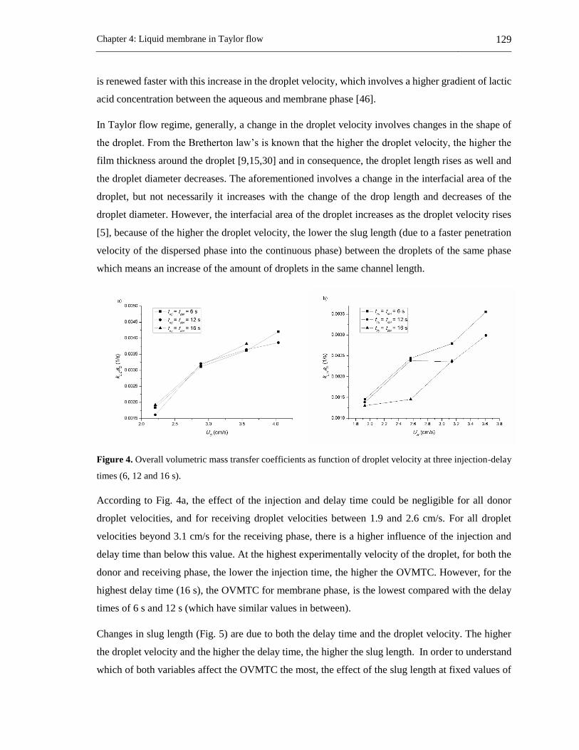
Chapter 4: Liquid membrane in Taylor flow 129
is renewed faster with this increase in the droplet velocity, which involves a higher gradient of lactic
acid concentration between the aqueous and membrane phase [46].
In Taylor flow regime, generally, a change in the droplet velocity involves changes in the shape of
the droplet. From the Bretherton law’s is known that the higher the droplet velocity, the higher the
film thickness around the droplet [9,15,30] and in consequence, the droplet length rises as well and
the droplet diameter decreases. The aforementioned involves a change in the interfacial area of the
droplet, but not necessarily it increases with the change of the drop length and decreases of the
droplet diameter. However, the interfacial area of the droplet increases as the droplet velocity rises
[5], because of the higher the droplet velocity, the lower the slug length (due to a faster penetration
velocity of the dispersed phase into the continuous phase) between the droplets of the same phase
which means an increase of the amount of droplets in the same channel length.
Figure 4. Overall volumetric mass transfer coefficients as function of droplet velocity at three injection-delay
times (6, 12 and 16 s).
According to Fig. 4a, the effect of the injection and delay time could be negligible for all donor
droplet velocities, and for receiving droplet velocities between 1.9 and 2.6 cm/s. For all droplet
velocities beyond 3.1 cm/s for the receiving phase, there is a higher influence of the injection and
delay time than below this value. At the highest experimentally velocity of the droplet, for both the
donor and receiving phase, the lower the injection time, the higher the OVMTC. However, for the
highest delay time (16 s), the OVMTC for membrane phase, is the lowest compared with the delay
times of 6 s and 12 s (which have similar values in between).
Changes in slug length (Fig. 5) are due to both the delay time and the droplet velocity. The higher
the droplet velocity and the higher the delay time, the higher the slug length. In order to understand
which of both variables affect the OVMTC the most, the effect of the slug length at fixed values of

130 Applications of a liquid membrane in Taylor flow regime (LMTF) on separation processes and
design of fermentation hybrid systems
the droplet is shown in Fig. 5. From these figures, two observations can be made. The higher the
droplet velocity, the higher the OVMTC. Secondly, at a fixed value of the velocity, the change of
the OVMTC with the slug length is almost negligible. Thus, the droplet velocity is the variable that
has the highest influence on the OVMTC, rather than the delay time.
Figure 5. Overall volumetric mass transfer coefficients as function of slug length at its respective droplets
velocity.
For all droplet velocities of the donor phase and at low droplets velocities of the receiving phase
(lower than 2.56 cm/s) there was no effect of the injection and delay time on the OVMTC, while at
high droplet velocities of the receiving phase (beyond 2.56 cm/s) there is a slight effect. This may
be because at low droplet velocities, the residence time of the droplets is high enough to achieve
mass transfer. In this way, the residence time of the droplets is affected by the droplet velocity and
for the channel length. In the experiments, the length channel was constant (348.8 cm), therefore,
the higher the droplet velocity, the lower the residence time of the droplets. Low residence times do
not allow for the entire mass transfer process.
Models for overall volumetric mass transfer coefficients prediction
The three proposed models were fitted using the experimental results of the overall volumetric mass
transfer coefficients using Eqs. (6)-(7) for adapted model 1, Eqs. (8)-(9) for adapted model 2 and
Eqs. (16)-(17) for the model proposed in this work. The calculated density and viscosity of the
membrane phase was 779.756 kg/m3 and 0.0054 Pa·s, respectively at 37 °C. The interfacial tension
at 37 °C was 30.44 mN/m. The density and viscosity for the donor phase was 1001.3 kg/m3 and
0.0012 Pa·s, respectively, and for the receiving phase 1023.9 kg/m3 and 0.7669 Pa·s, respectively.

Chapter 4: Liquid membrane in Taylor flow 131
The comparison of the three models with the experimental results is shown in Fig. 6. Fitted
parameters and the values of the R2 of each model are shown in Table 2. For the adapted model 2
the same values of the calculated OVMTC can be obtained for different values of the experimental
OVMTC. This is because this model is fully dependent on the droplet velocity, through Reynolds
and Capillary numbers, and the residence time. Thus, for a fixed value of droplet velocity, the same
value of the OVMTC with this model is achieved (circles in Fig. 6). On the other hand, the adapted
model 1 is not only a function of the droplet velocity, but also of the injected volume of the dispersed
phase, which allows studying variations of the calculated OVMTC at a fixed value of the droplet
velocity. For this reason, the R2 value for the OVMTC of the membrane phase of the adapted model
1 was higher than for the adapted model 2, but in spite of this, the value of R2 for the OVMTC of the
donor phase was similar for both models (slightly higher for the adapted model 2 than for the adapted
model 1).
Figure 6. Comparison of the experimental overall volumetric mass transfer coefficients with achieved by
models.
The model developed in this study has less scattering of the data and represents the best fit. This may
be related to the fact that this model includes variables such as injection time, slug length, and the
dimensionless relative velocity, while the other models are a function of less variables.
Experimentally, these variables showed a high influence on the OVNTC in the LMTF.
In the model developed in this work, the highest scattering of the data is observed at the highest
values of the OVMTC where the experimental flow rate of the membrane phase was 9.9 mL/min
(with an injection time of 6 s), while for low and medium values of the OVMTC the dispersion is
low where the experimental membrane flow rate was 4.5, 6.5 and 8.5 ml/min.

132 Applications of a liquid membrane in Taylor flow regime (LMTF) on separation processes and
design of fermentation hybrid systems
According to the values of the fitted parameters (the power of the models), the OVMTC (donor and
membrane) shown a high dependency on the product of the droplet velocity and the channel diameter
for the adapted model 1. Additionally, in the OVMTC for the donor phase there was an appreciable
influence of the term of the ratio equivalent diameter to inner diameter of the channel, while for the
membrane phase there was an appreciable influence of the ratio of the receiving droplet volume to
unit cell receiving phase and the ratio of receiving droplet velocity to interfacial tension. In the
adapted model 2, the OVMTC for both donor and membrane phase shows a high dependency on the
Capillary number.
Table 2. Fitted parameters of the three models for the OVMTC of donor and membrane phase and its respective
values of R2.
Model R2 Fitted parameters
j 1 2 3 4 5 6 7
Adapted
1
0.888 δj 0.0776 0.3342 1.7251 -0.0192 -1.1646 - -
0.901 δj' 0.0018 1.1103 1.0891 2.2484 -0.9758 - -
Adapted
2
0.896 λj 2.1588 0.2018 0.0942 0.1404 - - -
0.885 λj' 0.7188 0.0796 0.1453 0.0850 - - -
This
work
0.924 αj 0.0003 -1.5002 1.7079 20.4570 -1.1497 -0.2303 1.0673
0.913 αj' 0.0014 0.1679 -0.7666 2.0224 0.0309 -0.6909 -0.0390
In the model developed in this work, some variables such as, slug length, injection time and relative
velocity, are involved that are not included in the adapted models 1 and 2. These variables showed
an appreciable influence on the OVMTC. In the donor and membrane phase, the OVMTC showed
the highest dependency on the relative velocity. In the donor phase the highest dependency was
found for the reverse of the Reynolds and Capillary numbers, the ratio slug length to inner diameter
and the ratio inner diameter to the product donor droplet velocity to injection time. These parameters
are function of the donor velocity, physical properties of the fluids (density, viscosity and interfacial
tension) and slug length. On the other hand, in the membrane phase, the OVMTC was influenced by
the Capillary number, and the ratio inner diameter to channel length.
4.2.5 Conclusions
Overall volumetric mass transfer coefficients (OVMTC) were calculated from experimental results,
and three empirical correlations were fitted for the OVMTC prediction. From both experimental
OVMTC and correlations, the influence of some variables of the system was observed.
Chapter 4: Liquid membrane in Taylor flow 133
According to the experimental results, the variables that affect the overall volumetric mass transfer
coefficient the most were droplet velocities and injection time. The higher the droplet velocity and
the lower the injection time, the higher the overall mass transfer coefficient for both the donor and
membrane phase.
The OVMTC for the membrane phase is directly influenced by the OVMTC of the donor phase,
because the amount of lactic acid available to be transported from the membrane phase to the
receiving phase depends on the transport process of lactic acid from the donor to membrane phase.
The OVMTC can be predicted with a good agreement (R2 of 0.92) for donor phase and membrane
phase (R2 of 0.91). In the proposed model of this work the donor droplets velocity, relative velocity
for donor phase, injection time, slug length, density, viscosity, and interfacial tension have a high
influence on the OVMTC of the donor phase. The receiving droplet velocity, channel length (that
means residence time), relative velocity for receiving phase, the viscosity of the fluids and interfacial
tension have a high influence on the OVMTC of the membrane phase.
NOTATION
a Specific surface area (m2/m3)
C Molar concentration of solute (mol/L)
Ca Capillary number
d Inner diameter of the channel (m)
dd Droplet equivalent diameter (m)
Jss Steady state flux of solute through the membrane phase
K Distribution coefficient
kLa Overall volumetric mass transfer coefficient (1/s)
L Channel length (m)
Q Volumetric flow rate (m3/s)
Re Reynolds number
S Solute
t Time (s)
U Droplet velocity (m/s)
V Volume (m3)
W Relative velocity
α Fitted parameter of the developed model
δ Fitted parameter of the adapted model 1
γ Interfacial tension (N/m)
λ Fitted parameter of the adapted model 2
µ Viscosity (Pa·s)
τ Residence time (s)
ρ Density (kg/m3)
Subscripts and superscripts

134 Applications of a liquid membrane in Taylor flow regime (LMTF) on separation processes and
design of fermentation hybrid systems
0 Initial
calc Calculated data
del Delay
D Donor phase
eq In equilibrium
exp Experimental data
inj Injection
mix Mixture property between the disperse and continuous phases
M Membrane phase
R Receiving phase
T Total
UC Unit cell between the respective dispersed phase and the membrane phase
4.2.6 References
[1] J. Fontalvo, A.D. Pérez, Membrana Líquida y proceso para realizarlo, Colombian pending
patent, Rad. 15-131023.
[2] A.D. Pérez, Desarrollo y evaluación de un sistema de membrana líquida en flujo de Taylor
para la remoción de ácido láctico, Universidad Nacional de Colombia, 2014.
[3] M.T. Kreutzer, F. Kapteijn, J.A. Moulijn, C.R. Kleijn, J.J. Heiszwolf, Inertial and interfacial
effects on pressure drop of Taylor flow in capillaries, AIChE J. 51 (2005) 2428–2440.
[4] N. Di Miceli Raimondi, L. Prat, C. Gourdon, J. Tasselli, Experiments of mass transfer with
liquid-liquid slug flow in square microchannels, Chem. Eng. Sci. 105 (2014) 169–178.
[5] D. Tsaoulidis, P. Angeli, Effect of channel size on mass transfer during liquid-liquid plug
flow in small scale extractors, Chem. Eng. J. 262 (2015) 785–793.
[6] R.S. Abiev, Bubbles velocity, Taylor circulation rate and mass transfer model for slug flow
in milli- and microchannels, Chem. Eng. J. 227 (2013) 66–79.
[7] R. Gupta, D.F. Fletcher, B.S. Haynes, Taylor Flow in Microchannels: A Review of
Experimental and Computational Work, J. Comput. Multiph. Flows. 2 (2010) 1–31.
[8] A. Ufer, M. Mendorf, A. Ghaini, D.W. Agar, Liquid-Liquid Slug Flow Capillary
Microreactor, Chem. Eng. Technol. 34 (2011) 353–360.
[9] M.N. Kashid, I. Gerlach, S. Goetz, J. Franzke, J.F. Acker, F. Platte, D.W. Agar, S. Turek,
Internal circulation within the liquid slugs of a liquid-liquid slug-flow capillary microreactor,

Chapter 4: Liquid membrane in Taylor flow 135
Ind. Eng. Chem. Res. 44 (2005) 5003–5010.
[10] V.S. Kislik, Liquid Membranes Principles & Applications in Chemical Separation &
Wastewater Treatment, 1st ed., Elsevier B.V., Amsterdan, 2010.
[11] M. Sattari-Najafabadi, M. Nasr Esfahany, Z. Wu, B. Sundén, Hydrodynamics and mass
transfer in liquid-liquid non-circular microchannels: Comparison of two aspect ratios and
three junction structures, Chem. Eng. J. 322 (2017) 328–338.
[12] K.K. Singh, A.U. Renjith, K.T. Shenoy, Liquid-liquid extraction in microchannels and
conventional stage-wise extractors: A comparative study, Chem. Eng. Process. Process
Intensif. 98 (2015) 95–105.
[13] O. Jafari, M. Rahimi, F.H. Kakavandi, Liquid-liquid extraction in twisted micromixers,
Chem. Eng. Process. Process Intensif. 101 (2016) 33–40.
[14] M. N. Kashid, A. Renken, L. Kiwi-Minsker, Influence of Flow Regime on Mass Transfer in
Different Types of Microchannels, Ind. Eng. Chem. Res. 50 (2011) 6906–6914.
[15] M.N. Kashid, A. Renken, L. Kiwi-Minsker, Gas-liquid and liquid-liquid mass transfer in
microstructured reactors, Chem. Eng. Sci. 66 (2011) 3876–3897.
[16] M.N. Kashid, A. Gupta, A. Renken, L. Kiwi-Minsker, Numbering-up and mass transfer
studies of liquid-liquid two-phase microstructured reactors, Chem. Eng. J. 158 (2010) 233–
240.
[17] S.K. Kurt, I. Vural Gürsel, V. Hessel, K.D.P. Nigam, N. Kockmann, Liquid-liquid extraction
system with microstructured coiled flow inverter and other capillary setups for single-stage
extraction applications, Chem. Eng. J. 284 (2016) 764–777.
[18] D. Liu, K. Wang, Y. Wang, Y. Wang, G. Luo, A simple online phase separator for the
microfluidic mass transfer studies, Chem. Eng. J. 325 (2017) 342–349.
[19] F. Kaske, S. Dick, S.A. Pajoohi, D.W. Agar, The influence of operating conditions on the
mass transfer performance of a micro capillary contactor with liquid–liquid slug flow, Chem.
Eng. Process. Process Intensif. 108 (2016) 10–16.
[20] Susanti, J.G.M. Winkelman, B. Schuur, H.J. Heeres, J. Yue, Lactic Acid Extraction and Mass
Transfer Characteristics in Slug Flow Capillary Microreactors, Ind. Eng. Chem. Res. 55
(2016) 4691–4702.

136 Applications of a liquid membrane in Taylor flow regime (LMTF) on separation processes and
design of fermentation hybrid systems
[21] N. Aoki, S. Tanigawa, K. Mae, A new index for precise design and advanced operation of
mass transfer in slug flow, Chem. Eng. J. 167 (2011) 651–656.
[22] A. Matsuoka, K. Noishiki, K. Mae, Experimental study of the contribution of liquid film for
liquid-liquid Taylor flow mass transfer in a microchannel, Chem. Eng. Sci. 155 (2016) 306–
313.
[23] K.G. Biswas, S. Ray, G. Das, J.K. Basu, A simple flow device for enhanced mass transfer in
reduced dimensions, Chem. Eng. J. 279 (2015) 973–982.
[24] M.N. Kashid, D.W. Agar, S. Turek, CFD modelling of mass transfer with and without
chemical reaction in the liquid-liquid slug flow microreactor, Chem. Eng. Sci. 62 (2007)
5102–5109.
[25] M. Sattari-Najafabadi, M.N. Nasr Esfahany, Intensification of liquid-liquid mass transfer in
a circular microchannel in the presence of sodium dodecyl sulfate, Chem. Eng. Process.
Process Intensif. 117 (2017) 9–17.
[26] A.L. Dessimoz, L. Cavin, A. Renken, L. Kiwi-Minsker, Liquid-liquid two-phase flow
patterns and mass transfer characteristics in rectangular glass microreactors, Chem. Eng. Sci.
63 (2008) 4035–4044.
[27] A. Woitalka, S. Kuhn, K.F. Jensen, Scalability of mass transfer in liquid-liquid flow, Chem.
Eng. Sci. 116 (2014) 1–8.
[28] P. Plouffe, D.M. Roberge, A. Macchi, Liquid-liquid flow regimes and mass transfer in
various micro-reactors, Chem. Eng. J. 300 (2016) 9–19.
[29] P. Plouffe, M. Bittel, J. Sieber, D.M. Roberge, A. Macchi, On the scale-up of micro-reactors
for liquid-liquid reactions, Chem. Eng. Sci. 143 (2016) 216–225.
[30] A. Ghaini, M.N. Kashid, D.W. Agar, Effective interfacial area for mass transfer in the liquid-
liquid slug flow capillary microreactors, Chem. Eng. Process. Process Intensif. 49 (2010)
358–366.
[31] N. Di Miceli Raimondi, L. Prat, C. Gourdon, P. Cognet, Direct numerical simulations of mass
transfer in square microchannels for liquid-liquid slug flow, Chem. Eng. Sci. 63 (2008) 5522–
5530.
Chapter 4: Liquid membrane in Taylor flow 137
[32] A.H.P. Skelland, R.M. Wellek, Resistance to mass transfer inside droplets, AIChE J. 10
(1964) 491–496.
[33] G. Berčič, A. Pintar, The role of gas bubbles and liquid slug lengths on mass transport in the
Taylor flow through capillaries, Chem. Eng. Sci. 52 (1997) 3709–3719.
[34] J.M. van Baten, R. Krishna, CFD simulations of mass transfer from Taylor bubbles rising in
circular capillaries, Chem. Eng. Sci. 59 (2004) 2535–2545.
[35] C.O. Vandu, H. Liu, R. Krishna, Mass transfer from Taylor bubbles rising in single
capillaries, Chem. Eng. Sci. 60 (2005) 6430–6437.
[36] J. Yue, L. Luo, Y. Gonthier, G. Chen, Q. Yuan, An experimental study of air-water Taylor
flow and mass transfer inside square microchannels, Chem. Eng. Sci. 64 (2009) 3697–3708.
[37] C. Mendoza, A theorem for rayleigh’s method of dimensional analysis and its proof, Mech.
Res. Commun. 21 (1994) 103–107.
[38] G.I. Taylor, Deposition of a viscous fluid on a plane surface, J. Fluid Mech. 9 (1961) 218.
[39] D. Yankov, J. Molinier, J. Albet, G. Malmary, G. Kyuchoukov, Lactic acid extraction from
aqueous solutions with tri-n-octylamine dissolved in decanol and dodecane, Biochem. Eng.
J. 21 (2004) 63–71.
[40] M. Matsumoto, T. Takagi, K. Kondo, Separation of lactic acid using polymeric membrane
containing a mobile carrier, J. Ferment. Bioeng. 85 (1998) 483–487.
[41] S.L. Oswal, R.G. Sindhe, A.T. Patel, J.P. Dave, S.G. Patel, B.M. Patel, Study of viscosity of
mono-, di-, and trialkylamines, Int. J. Thermophys. 13 (1992) 617–628.
[42] D.R. Caudwell, J.P.M. Trusler, V. Vesovic, W.A. Wakeham, The viscosity and density of n-
dodecane and n-octadecane at pressures up to 200 MPa and temperatures up to 473 K, Int. J.
Thermophys. 25 (2004) 1339–1352.
[43] M.A. Saleh, S. Akhtar, S. Begum, M.S. Ahmed, S.K. Begum, Density and viscosity of 1-
alkanols, Phys. Chem. Liq. 42 (2004) 615–623.
[44] A. Bahramian, A. Danesh, Prediction of liquid-liquid interfacial tension in multi-component
systems, Fluid Phase Equilib. 221 (2004) 197–205.
[45] D. Villers, J.K. Platten, Temperature dependence of the interfacial tension between water and

138 Applications of a liquid membrane in Taylor flow regime (LMTF) on separation processes and
design of fermentation hybrid systems
long-chain alcohols, J. Phys. Chem. 92 (1988) 4023–4024.
[46] L. Arsenjuk, F. Kaske, J. Franzke, D.W. Agar, Experimental investigation of wall film
renewal in liquid–liquid slug flow, Int. J. Multiph. Flow. 85 (2016) 177–185.

Chapter 5: Hybrid system 139
5. Chapter 5: Hybrid system
140 Applications of a liquid membrane in Taylor flow regime (LMTF) on separation processes and
design of fermentation hybrid systems
5.1 Integration of a liquid membrane in Taylor flow regime
with a fermentation by Lactobacillus casei ATCC 393 for
in-situ lactic acid removal7
Abstract
A new type of liquid membranes called liquid membrane in Taylor flow was integrated to a lactic
acid fermentation, using Lactobacillus casei ATCC 393, for lactic acid removal during fermentation.
The performance in terms of lactic acid production of the hybrid batch system is compared to a
conventional batch fermentation. Lactic acid removal rate increases proportionally with the LA
concentration within the fermenter. The lactic acid, the biomass production and the LA productivity
in the hybrid system increased by 41.8, 12 and 26.6%, respectively, as compared to the conventional
batch fermentation. However, toxicity effects reduce LA to glucose yield in 15.9% as compared to
conventional fermentation. Liquid membranes in Taylor flow results promising for enhancing batch
and continuous fermentation processes by a hybrid system.
7 This section has been published in: Chemical Engineering & Processing: Process Intensification 140 (2019)
85–90: Alan D. Perez, Sneyder Rodríguez-Barona, Javier Fontalvo.

Chapter 5: Hybrid system 141
5.1.1 Introduction
Lactic acid fermentation
Lactic acid (LA) is a commodity chemical with significant applications in various fields [1,2] such
as food (as additive and preservative), cosmetic and pharmaceutical industries [2–5]. Also, it is used
as raw material of several chemicals, for instance, acrylic acid, propylene glycol, acetaldehyde,
among others [1,2]. Additionally, LA can be used as a monomer for the production of polylactic acid
(PLA) a biodegradable polymer [6,7].
LA can be produced by two routes, chemical synthesis or by carbohydrate fermentation [8–11].
Chemical synthesis produces the racemic mixture of the LA, while by fermentation route it can be
produced pure L(+)-lactic acid [7,9,10,12] or pure D(-)-lactic acid, depending on the used
microorganism [7]. D(-)-lactic acid is harmful to humans at high levels, whereas L(+)-lactic acid is
assimilated by the human body [13]. Bacterial fermentation route offer advantages over chemical
synthesis because it can be used cheap raw materials, low production temperatures, with low energy
consumption and, it can be obtained one of the two isomers of LA [7,9,14].
Although 90% of the LA production is achieved through bacterial fermentation [10,13], the
biotechnological route has used around 100 years without significant technological changes [15].
Batch processes have been the most commonly operation mode at industrial level [11,13].
Conventional recovery of LA from the fermentation broth is by precipitation, followed by filtration
with the addition of sulfuric acid [2,15]. Subsequently, the LA is purified by activated carbon,
evaporation and crystallization [1,15]. The conventional separation process for the production of LA
is expensive and produces a significant amount of calcium sulfate (gypsum) as solid waste [1,2].
Some drawbacks to overcome in the conventional LA biotechnological production [15] are: Cell
growth inhibition (by product and substrate), the use of neutralizers, low yield and productivity, and
the high overall cost of the whole process [1,15]. The product inhibition of the lactic acid bacteria
(LAB) is due to the acidic conditions affects the cytoplasm, the proton motive forces fail [5], and as
consequence low concentrations of LA and biomass are obtained achieving low yields [2,4,12].
Lactic acid removal from the fermentation broth
In order to reduce the cost of the biotechnological LA process production, current studies have been
addressed on the modifications of LAB to achieve acid-tolerant strains [1,11,15,16], on to obtain
raw materials of low cost [11], and on the application of new separation technologies on fed-batch,
semi-continuous and continuous fermentations [11]. However, since the cost of the separation and
final purification steps of the conventional LA production process is around 50% of the total cost of

142 Applications of a liquid membrane in Taylor flow regime (LMTF) on separation processes and
design of fermentation hybrid systems
the process [1,2,15,17], several separation technologies for LA recovery from fermentation broth
have attracted great attention in the recent years [2,3]. LA removal is also important from the point
of view of product inhibition [18], because with the application of a suitable selective separation
technique on the fermentation process it is possible to reduce the product inhibition effect [5,18].
The explored technologies are solvent and reactive extraction, adsorption, ion exchange, membrane
separation, electrodialysis and reactive distillation [2,3,10,18,19]. One of the most studied separation
technologies for LA removal has been reactive extraction [6,10,17,20–24]. However, this process
requires high volumes of solvent and the use of back-extraction for regeneration of the solvent
[5,10,25].
Liquid membrane separation is a membrane technology where the extractants and diluents of the
reactive extraction can be used as a membrane phase [26]. In contrast to reactive extraction, it is not
required the additional step of back-extraction, because both extraction and back-extraction occur
simultaneously with a membrane process in a single unit [25,26]. Liquid membranes are a potential
separation technology to be integrated with a fermentation process for in-situ LA removal which has
been tested in several studies [4,11,17,27–32]. The liquid membrane in Taylor flow (LMTF) is a
novel membrane technology that preserves the advantages of conventional emulsion liquid
membranes while overcomes the stability problems of emulsion systems [33–35]. The LMTF has
been developed and tested for LA removal [33–35].
This work analyses a hybrid system which involves the LMTF for in-situ LA removal from a batch
LA fermentation (by Lactobacillus casei ATCC 393). The performance of the hybrid system is
compared to a batch conventional fermentation in terms of LA productivity, yield and LA removal
level.
5.1.2 Experimental
Strain and culture media
Fermentation broths were prepared at 10 g/L of tryptose (Scharlau), 20 g/L of dextrose anhydrous
(Loba Chemie), 5 g/L of sodium acetate (anhydrous, Merck), 2 g/L of ammonium citrate dibasic
(Sigma-Aldrich), 0.2 g/L of magnesium sulfate (Heptahydrate, Loba Chemie), 0.05 g/L of
manganese sulfate (monohydrate, Loba Chemie), and 2 g/L of potassium phosphate dibasic
(anhydrous, Loba Chemie). For each fermentation (batch and hybrid) it was prepared 70 mL of
sterile fermentation broth with distilled water. The used lactic acid bacteria (LAB) for the
fermentation was Lactobacillus casei ATCC 393 (Microbiologics). Pre-inoculum was prepared

Chapter 5: Hybrid system 143
using two cryogenized pearls of the LAB within 10 mL of MRS broth (Scharlau) into an incubator
(RI 115, Binder) at 37 ºC. The inoculum was prepared at 37 ºC in 10 mL of the fermentation broth
at 10 vol% of a culture of 24 h.
The experimental conditions and the fermentation broth for batch and hybrid fermentation systems
were the same.
Fermentations
Fermentations were carried out at 37 ºC in a glass flask of 100 mL (GL 45, Duran®) and controlling
the temperature with a water-bath using a digital hotplate stirrer (DAIHAN MaXtir™ 500) during
22 h. Samples of 0.3 mL were taken from the fermentation broth each two hours for lactic acid and
glucose quantification by HPLC. One sample of 2 mL was taken at the beginning (0 h) and another
sample at the end (22 h) of the fermentation for biomass quantification by dry cell weight method.
Fermentation volumes of 50 mL at 5 vol% of the inoculum were used to have a LA removal rate by
the liquid membrane of the same order of magnitude that the LA production rate by the bacteria.
Liquid membrane in Taylor flow for lactic acid removal
The liquid membrane in Taylor flow (LMTF) is a new alternative of contact among the phases of a
conventional liquid membrane (donor, membrane and receiving phases), which extends the Taylor
flow to a three-phase system [33–35]. In LMTF the enhanced mass transfer is due to the features of
the Taylor flow [36]. In the LMTF, the membrane phase (M) flows as a continuous phase within a
channel while donor (D) and receiving (R) phases flows as a subsequent train of droplets (Figure
1a). The LA is transferred from the donor phase to the membrane phase and, from here, to the
receiving phase. Donor and receiving phases are aqueous while the membrane is an organic phase
(Figure 1b).
The injection of the dispersed phases (donor and receiving) is carried out by cycles. Each injection
cycle follows the next four steps: First, the donor phase is injected during an injection time of the
donor phase. Then, the injection of the donor phase is stopped and a delay time elapses. Afterward,
the receiving phase starts to inject during an injection time of receiving phase, and in the fourth step,
the receiving phase injection is stopped and a delay time elapses again [33,34]. At the outside of the
channel, the receiving phase, rich of solute, and the donor phase, poor in solute, are fed to separate
containers of a settler. In the containers of the settler the membrane phase is split from each dispersed
phase. Then, the membrane phase is recycled to the LMTF system (Figure 1a).

144 Applications of a liquid membrane in Taylor flow regime (LMTF) on separation processes and
design of fermentation hybrid systems
The membrane phase is composed by tri-iso-octylamine (10 vol%), 1-dodecanol (40 vol%) and, n-
dodecane (50 vol%), where the tertiary amine is the carrier (for facilitated transport), the alkane and
the alcohol are the inert, and active diluents, respectively [34,37]. Tri-iso-octylamine (TiOA), 1-
dodecanol, n-dodecane were supplied by Merck (all reagents for synthesis). This membrane phase
was previously tested both by molecular toxicity on the Lactobacillus casei ATCC 393 [38] and by
liquid-liquid equilibrium with LA aqueous solutions [37]. This membrane phase is able to remove
LA while the molecular toxicity on the bacteria is relatively low [37].
Figure 1a. Experimental set-up of the LMTF for solute
removal [33,34]. D: Donor phase rich in the solute. R:
Fresh receiving phase (free of solute). M: Membrane
phase. D*: Donor phase poor in the solute. R*: Receiving
phase rich in the solute.
Figure 1b. Schematic solute (S) transport
process between two adjacent droplets (donor
and receiving) through the membrane phase for
a LMTF system.
The donor phase is an aqueous solution which contains LA to remove or the fermentation broth free
of biomass. The receiving phase is an aqueous solution of sodium carbonate (anhydrous, supplied
by Merck) at 12 g/L prepared with water type I (Barnstead™ Nanopure™).
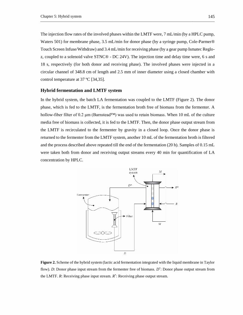
Chapter 5: Hybrid system 145
The injection flow rates of the involved phases within the LMTF were, 7 mL/min (by a HPLC pump,
Waters 501) for membrane phase, 3.5 mL/min for donor phase (by a syringe pump, Cole-Parmer®
Touch Screen Infuse/Withdraw) and 3.4 mL/min for receiving phase (by a gear pump Ismatec Reglo-
z, coupled to a solenoid valve STNC® - DC 24V). The injection time and delay time were, 6 s and
18 s, respectively (for both donor and receiving phase). The involved phases were injected in a
circular channel of 348.8 cm of length and 2.5 mm of inner diameter using a closed chamber with
control temperature at 37 ºC [34,35].
Hybrid fermentation and LMTF system
In the hybrid system, the batch LA fermentation was coupled to the LMTF (Figure 2). The donor
phase, which is fed to the LMTF, is the fermentation broth free of biomass from the fermenter. A
hollow-fiber filter of 0.2 µm (Barnstead™) was used to retain biomass. When 10 mL of the culture
media free of biomass is collected, it is fed to the LMTF. Then, the donor phase output stream from
the LMTF is recirculated to the fermenter by gravity in a closed loop. Once the donor phase is
returned to the fermenter from the LMTF system, another 10 mL of the fermentation broth is filtered
and the process described above repeated till the end of the fermentation (20 h). Samples of 0.15 mL
were taken both from donor and receiving output streams every 40 min for quantification of LA
concentration by HPLC.
Figure 2. Scheme of the hybrid system (lactic acid fermentation integrated with the liquid membrane in Taylor
flow). D: Donor phase input stream from the fermenter free of biomass. D*: Donor phase output stream from
the LMTF. R: Receiving phase input stream. R*: Receiving phase output stream.

146 Applications of a liquid membrane in Taylor flow regime (LMTF) on separation processes and
design of fermentation hybrid systems
The efficiency of LA removal is calculated by Eq. (1) where LAremoved is the mass of LA removed
from donor phase in grams and LA0 is the inlet LA mass in grams in the donor phase:
100(%)0
LA
LAE removed
(1)
Analytical methods
Concentrations of LA and glucose were measured by HPLC (Hitachi LaChrom Elite®) with an
ORH-801 column (Chrom Tech), an aqueous solution of 0.01 N of sulfuric acid for the mobile phase
(at 0.8 mL/min), and a RI detector at 45 °C. For the preparation of the mobile phase, it was used
sulfuric acid (for analysis) supplied by Merck. For calibration of glucose, it was used D(+)-glucose
(anhydrous for biochemistry) supplied by Merck. The calibration of LA was prepared from a stock
solution of LA at 150 g/L previously heated at 90 °C under total reflux between 8-10 hours for dimer
hydrolysis [6,35,37]. The LA stock solution was prepared with L(+)-lactic acid supplied by Scharlau,
which purity was assessed by titration with sodium hydroxide (Merck) using Metrohm automatic
titrator (702 SM Titrino, 703 TI Stand). All aqueous solutions for calibration were prepared with
water type I.
For biomass quantification, it was used Eppendorf tubes of 2 mL. The Eppendorf is dried in an oven
(Binder) at 100 ºC during 36 h. Once the Eppendorf is dried, it is weighing on a precision scale
(Dhaus) and then it is returned to the oven (at 100 ºC) for storage till the sample of the fermentation
broth will be taken. Once the sample is taken from the fermentation broth, the Eppendorf is filled
with 2 mL of sample (fermentation broth) and subsequently, the Eppendorf is centrifuged at 10000
rpm during 15 mins (Centrifuge 5415 C, Eppendorf). Afterward, the supernatant liquid of the
centrifuged Eppendorf is discarded, the Eppendorf is filled with 1 mL of distilled water, agitated in
a Bio vortex (Boeco) around 1 min and then it is centrifuged at the aforementioned conditions.
Afterward, the supernatant liquid of the centrifuged Eppendorf is discarded and the Eppendorf is
moved to the oven to be dried (at 100 ºC). The Eppendorf is weighing every 12 h till the weight of
the Eppendorf will be constant.
5.1.3 Results and discussion
Improvements on the LA productivity and yield are expected when the LA is continuously removed
from fermentation because the product inhibition effect is reduced [39]. The accumulation of LA
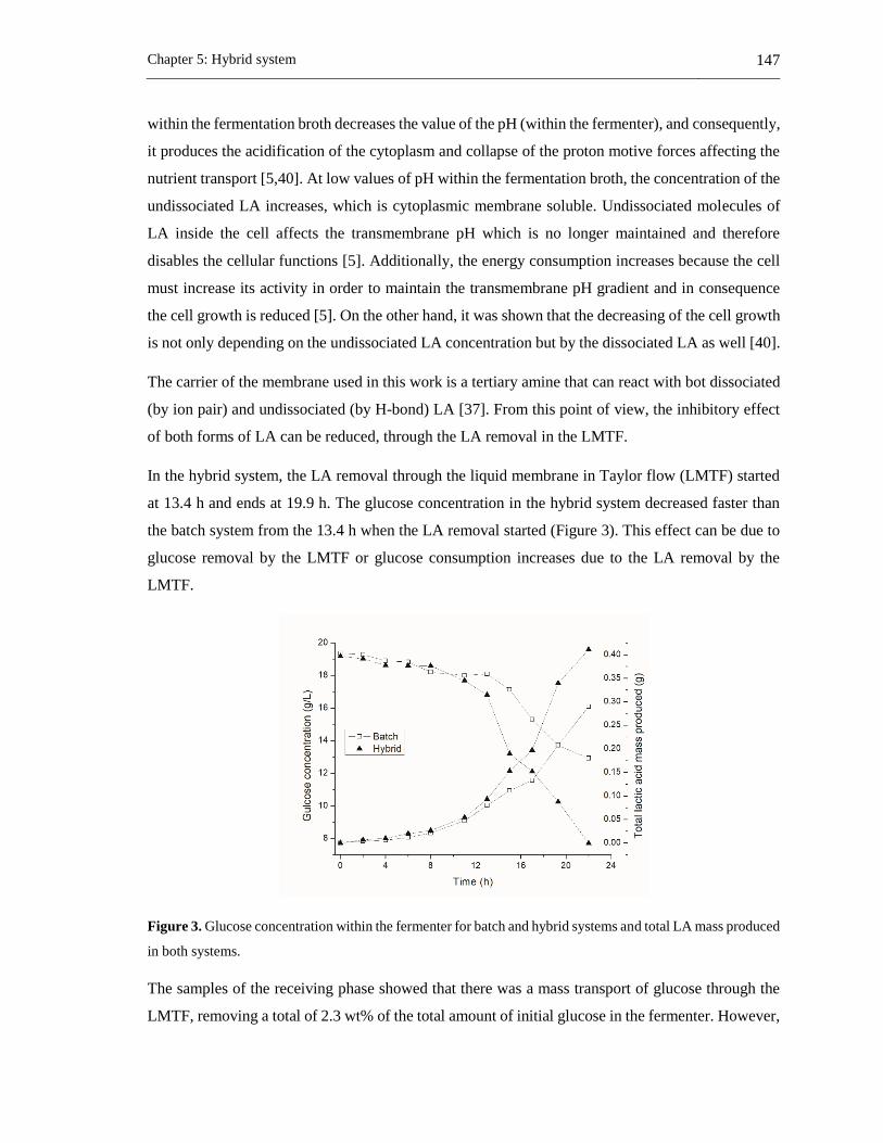
Chapter 5: Hybrid system 147
within the fermentation broth decreases the value of the pH (within the fermenter), and consequently,
it produces the acidification of the cytoplasm and collapse of the proton motive forces affecting the
nutrient transport [5,40]. At low values of pH within the fermentation broth, the concentration of the
undissociated LA increases, which is cytoplasmic membrane soluble. Undissociated molecules of
LA inside the cell affects the transmembrane pH which is no longer maintained and therefore
disables the cellular functions [5]. Additionally, the energy consumption increases because the cell
must increase its activity in order to maintain the transmembrane pH gradient and in consequence
the cell growth is reduced [5]. On the other hand, it was shown that the decreasing of the cell growth
is not only depending on the undissociated LA concentration but by the dissociated LA as well [40].
The carrier of the membrane used in this work is a tertiary amine that can react with bot dissociated
(by ion pair) and undissociated (by H-bond) LA [37]. From this point of view, the inhibitory effect
of both forms of LA can be reduced, through the LA removal in the LMTF.
In the hybrid system, the LA removal through the liquid membrane in Taylor flow (LMTF) started
at 13.4 h and ends at 19.9 h. The glucose concentration in the hybrid system decreased faster than
the batch system from the 13.4 h when the LA removal started (Figure 3). This effect can be due to
glucose removal by the LMTF or glucose consumption increases due to the LA removal by the
LMTF.
Figure 3. Glucose concentration within the fermenter for batch and hybrid systems and total LA mass produced
in both systems.
The samples of the receiving phase showed that there was a mass transport of glucose through the
LMTF, removing a total of 2.3 wt% of the total amount of initial glucose in the fermenter. However,
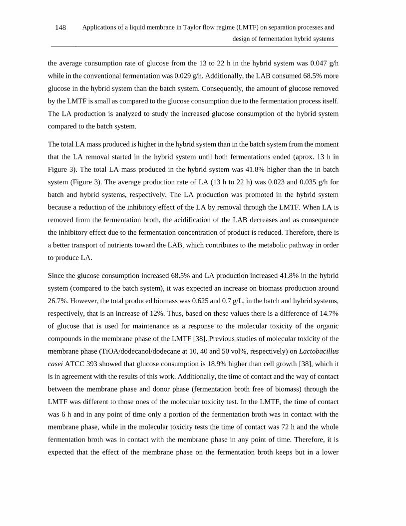
148 Applications of a liquid membrane in Taylor flow regime (LMTF) on separation processes and
design of fermentation hybrid systems
the average consumption rate of glucose from the 13 to 22 h in the hybrid system was 0.047 g/h
while in the conventional fermentation was 0.029 g/h. Additionally, the LAB consumed 68.5% more
glucose in the hybrid system than the batch system. Consequently, the amount of glucose removed
by the LMTF is small as compared to the glucose consumption due to the fermentation process itself.
The LA production is analyzed to study the increased glucose consumption of the hybrid system
compared to the batch system.
The total LA mass produced is higher in the hybrid system than in the batch system from the moment
that the LA removal started in the hybrid system until both fermentations ended (aprox. 13 h in
Figure 3). The total LA mass produced in the hybrid system was 41.8% higher than the in batch
system (Figure 3). The average production rate of LA (13 h to 22 h) was 0.023 and 0.035 g/h for
batch and hybrid systems, respectively. The LA production was promoted in the hybrid system
because a reduction of the inhibitory effect of the LA by removal through the LMTF. When LA is
removed from the fermentation broth, the acidification of the LAB decreases and as consequence
the inhibitory effect due to the fermentation concentration of product is reduced. Therefore, there is
a better transport of nutrients toward the LAB, which contributes to the metabolic pathway in order
to produce LA.
Since the glucose consumption increased 68.5% and LA production increased 41.8% in the hybrid
system (compared to the batch system), it was expected an increase on biomass production around
26.7%. However, the total produced biomass was 0.625 and 0.7 g/L, in the batch and hybrid systems,
respectively, that is an increase of 12%. Thus, based on these values there is a difference of 14.7%
of glucose that is used for maintenance as a response to the molecular toxicity of the organic
compounds in the membrane phase of the LMTF [38]. Previous studies of molecular toxicity of the
membrane phase (TiOA/dodecanol/dodecane at 10, 40 and 50 vol%, respectively) on Lactobacillus
casei ATCC 393 showed that glucose consumption is 18.9% higher than cell growth [38], which it
is in agreement with the results of this work. Additionally, the time of contact and the way of contact
between the membrane phase and donor phase (fermentation broth free of biomass) through the
LMTF was different to those ones of the molecular toxicity test. In the LMTF, the time of contact
was 6 h and in any point of time only a portion of the fermentation broth was in contact with the
membrane phase, while in the molecular toxicity tests the time of contact was 72 h and the whole
fermentation broth was in contact with the membrane phase in any point of time. Therefore, it is
expected that the effect of the membrane phase on the fermentation broth keeps but in a lower
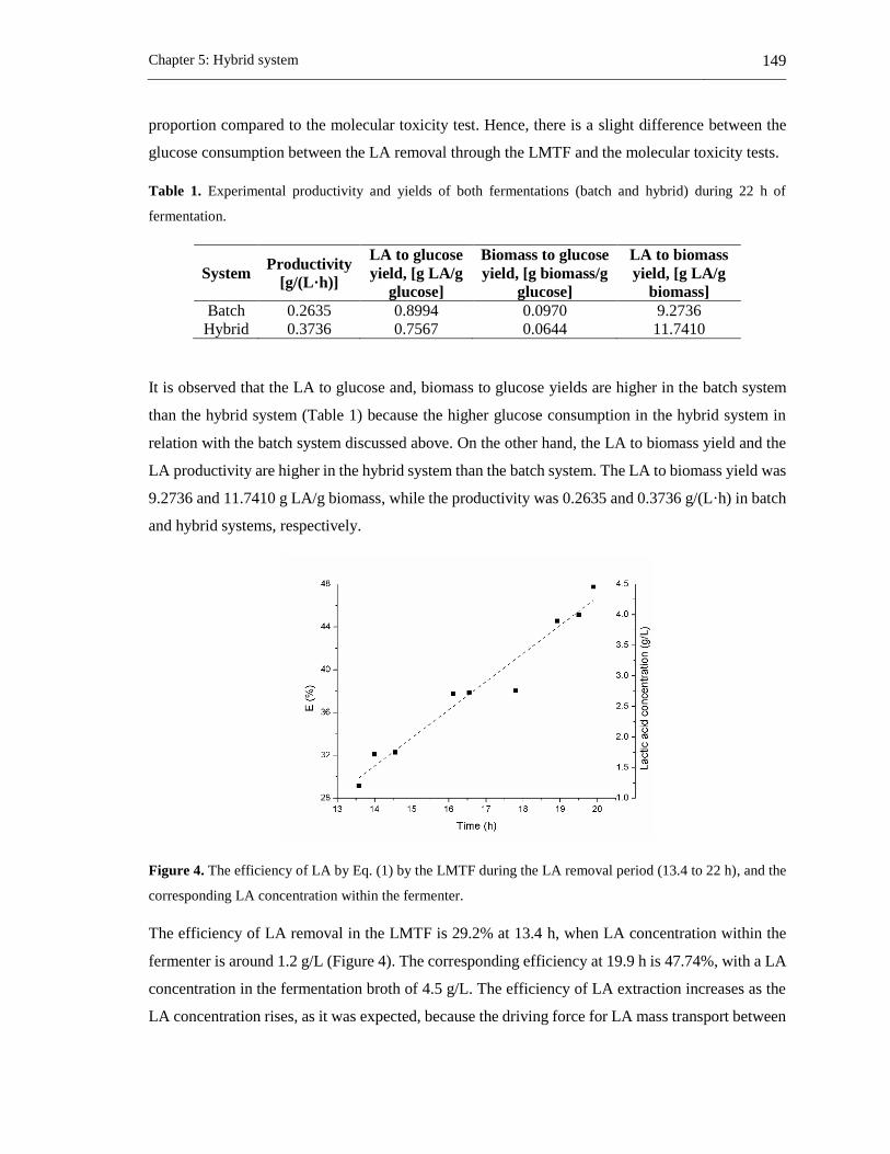
Chapter 5: Hybrid system 149
proportion compared to the molecular toxicity test. Hence, there is a slight difference between the
glucose consumption between the LA removal through the LMTF and the molecular toxicity tests.
Table 1. Experimental productivity and yields of both fermentations (batch and hybrid) during 22 h of
fermentation.
System Productivity
[g/(L·h)]
LA to glucose
yield, [g LA/g
glucose]
Biomass to glucose
yield, [g biomass/g
glucose]
LA to biomass
yield, [g LA/g
biomass]
Batch 0.2635 0.8994 0.0970 9.2736
Hybrid 0.3736 0.7567 0.0644 11.7410
It is observed that the LA to glucose and, biomass to glucose yields are higher in the batch system
than the hybrid system (Table 1) because the higher glucose consumption in the hybrid system in
relation with the batch system discussed above. On the other hand, the LA to biomass yield and the
LA productivity are higher in the hybrid system than the batch system. The LA to biomass yield was
9.2736 and 11.7410 g LA/g biomass, while the productivity was 0.2635 and 0.3736 g/(L·h) in batch
and hybrid systems, respectively.
Figure 4. The efficiency of LA by Eq. (1) by the LMTF during the LA removal period (13.4 to 22 h), and the
corresponding LA concentration within the fermenter.
The efficiency of LA removal in the LMTF is 29.2% at 13.4 h, when LA concentration within the
fermenter is around 1.2 g/L (Figure 4). The corresponding efficiency at 19.9 h is 47.74%, with a LA
concentration in the fermentation broth of 4.5 g/L. The efficiency of LA extraction increases as the
LA concentration rises, as it was expected, because the driving force for LA mass transport between
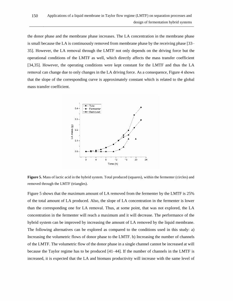
150 Applications of a liquid membrane in Taylor flow regime (LMTF) on separation processes and
design of fermentation hybrid systems
the donor phase and the membrane phase increases. The LA concentration in the membrane phase
is small because the LA is continuously removed from membrane phase by the receiving phase [33–
35]. However, the LA removal through the LMTF not only depends on the driving force but the
operational conditions of the LMTF as well, which directly affects the mass transfer coefficient
[34,35]. However, the operating conditions were kept constant for the LMTF and thus the LA
removal can change due to only changes in the LA driving force. As a consequence, Figure 4 shows
that the slope of the corresponding curve is approximately constant which is related to the global
mass transfer coefficient.
Figure 5. Mass of lactic acid in the hybrid system. Total produced (squares), within the fermenter (circles) and
removed through the LMTF (triangles).
Figure 5 shows that the maximum amount of LA removed from the fermenter by the LMTF is 25%
of the total amount of LA produced. Also, the slope of LA concentration in the fermenter is lower
than the corresponding one for LA removal. Thus, at some point, that was not explored, the LA
concentration in the fermenter will reach a maximum and it will decrease. The performance of the
hybrid system can be improved by increasing the amount of LA removed by the liquid membrane.
The following alternatives can be explored as compared to the conditions used in this study: a)
Increasing the volumetric flows of donor phase to the LMTF. b) Increasing the number of channels
of the LMTF. The volumetric flow of the donor phase in a single channel cannot be increased at will
because the Taylor regime has to be produced [41–44]. If the number of channels in the LMTF is
increased, it is expected that the LA and biomass productivity will increase with the same level of

Chapter 5: Hybrid system 151
molecular toxicity shown in this study. Molecular toxicity does not depend on interfacial area but on
the amount of organics dissolved in the fermentation broth.
5.1.4 Conclusions
A hybrid system of fermentation for lactic acid (LA) production with Lactobacillus casei ATCC 393
and LA removal by a liquid membrane in Taylor flow was experimentally tested and compared to a
conventional fermentation. The hybrid batch process shows a LA and biomass production of 41.8%
and 12% higher than the convention batch fermentation, respectively. Consequently, LA
productivity of the hybrid process is 25.8% higher than the conventional fermentation.
However, the glucose consumption of the hybrid system was 68.5% higher than in conventional
fermentation. In the hybrid system, the glucose intake of the biomass is partially (12%) used for
maintenance as a response to molecular toxicity and thus, the LA to glucose yield is lower (15.9%)
than in a conventional fermentation.
The LA extraction efficiency of the LMTF system increases as the LA concentration of the
fermentation broth rises. This efficiency can be improved if several channels are used in the LMTF.
The LMTF can be integrated with fermentation processes to remove metabolites and enhance both
LA and biomass productivity, however molecular toxicity issues could reduce LA to glucose yield.
5.1.5 References
[1] M. Singhvi, T. Zendo, K. Sonomoto, Free lactic acid production under acidic conditions by
lactic acid bacteria strains: challenges and future prospects, Appl. Microbiol. Biotechnol. 102
(2018) 5911–5924. doi:10.1007/s00253-018-9092-4.
[2] K.L. Wasewar, A.A. Yawalkar, J.A. Moulijn, V.G. Pangarkar, Fermentation of Glucose to
Lactic Acid Coupled with Reactive Extraction: A Review, Ind. Eng. Chem. Res. 43 (2004)
5969–5982. doi:10.1021/ie049963n.
[3] N. Phanthumchinda, S. Thitiprasert, S. Tanasupawat, S. Assabumrungrat, N. Thongchul,
Process and cost modeling of lactic acid recovery from fermentation broths by membrane-
based process, Process Biochem. 68 (2018) 205–213. doi:10.1016/j.procbio.2018.02.013.
[4] M. Othman, A.B. Ariff, H. Wasoh, M.R. Kapri, M. Halim, Strategies for improving
production performance of probiotic Pediococcus acidilactici viable cell by overcoming

152 Applications of a liquid membrane in Taylor flow regime (LMTF) on separation processes and
design of fermentation hybrid systems
lactic acid inhibition, AMB Express. 7 (2017). doi:10.1186/s13568-017-0519-6.
[5] M. Othman, A.B. Ariff, L. Rios-Solis, M. Halim, Extractive Fermentation of Lactic Acid in
Lactic Acid Bacteria Cultivation: A Review, Front. Microbiol. 8 (2017) 1–7.
doi:10.3389/fmicb.2017.02285.
[6] A.D. Pérez, S. Rodríguez-Barona, J. Fontalvo, Liquid–Liquid Equilibria for Trioctylamine/1-
Dodecanol/Lactic Acid/Water System at 306.1, 310.1 and 316.1 K: Experimental Data and
Prediction, J. Chem. Eng. Data. 61 (2016) 2269–2276. doi: 10.1021/acs.jced.5b00955.
[7] M.A. Abdel-Rahman, Y. Tashiro, K. Sonomoto, Recent advances in lactic acid production
by microbial fermentation processes., Biotechnol. Adv. 31 (2013) 877–902.
doi:10.1016/j.biotechadv.2013.04.002.
[8] P. Pal, J. Sikder, S. Roy, L. Giorno, Process intensification in lactic acid production: A review
of membrane based processes, Chem. Eng. Process. Process Intensif. 48 (2009) 1549–1559.
doi.org/10.1016/j.cep.2009.09.003.
[9] T. Ghaffar, M. Irshad, Z. Anwar, T. Aqil, Z. Zulifqar, A. Tariq, M. Kamran, N. Ehsan, S.
Mehmood, Recent trends in lactic acid biotechnology: A brief review on production to
purification, J. Radiat. Res. Appl. Sci. 7 (2014) 222–229. doi:10.1016/j.jrras.2014.03.002.
[10] A. Komesu, M.R. Wolf Maciel, R. Maciel Filho, Separation and Purification Technologies
for Lactic Acid – A Brief Review, BioResources. 12 (2017) 6885–6901.
doi:10.15376/biores.12.3.6885-6901.
[11] C. Rodrigues, L.P.S. Vandenberghe, A.L. Woiciechowski, J. de Oliveira, L.A.J. Letti, C.R.
Soccol, Production and Application of Lactic Acid, in: Curr. Dev. Biotechnol. Bioeng.,
Elsevier, 2017: pp. 543–556. doi:10.1016/B978-0-444-63662-1.00024-5.
[12] M.A. Abdel-Rahman, K. Sonomoto, Opportunities to overcome the current limitations and
challenges for efficient microbial production of optically pure lactic acid, J. Biotechnol. 236
(2016) 176–192. doi:10.1016/j.jbiotec.2016.08.008.
[13] J. Vijayakumar, R. Aravindand, T. Viruthagiri, Recent Trends in the Production, Purification
and Application of Lactic Acid, Chem. Biochem. Eng. Q. 22 (2008) 245–264.
[14] M. Boonmee, O. Cotano, S. Amnuaypanich, N. Grisadanurak, Improved Lactic Acid
Production by In Situ Removal of Lactic Acid During Fermentation and a Proposed Scheme

Chapter 5: Hybrid system 153
for Its Recovery, Arab. J. Sci. Eng. 41 (2016) 2067–2075. doi:10.1007/s13369-015-1824-5.
[15] C. Miller, A. Fosmer, B. Rush, T. McMullin, D. Beacom, P. Suominen, Industrial Production
of Lactic Acid, in: Ref. Modul. Life Sci., Elsevier, 2017: pp. 179–188. doi:10.1016/B978-0-
12-809633-8.09142-1.
[16] I. Eş, A. Mousavi Khaneghah, F.J. Barba, J.A. Saraiva, A.S. Sant’Ana, S.M.B. Hashemi,
Recent advancements in lactic acid production - a review, Food Res. Int. 107 (2018) 763–
770. doi:10.1016/j.foodres.2018.01.001.
[17] N. Tik, E. Bayraktar, Ül. Mehmetoglu, In situ reactive extraction of lactic acid from
fermentation media, J. Chem. Technol. Biotechnol. 76 (2001) 764–768.
doi.org/10.1002/jctb.449.
[18] E. Cubas-Cano, C. González-Fernández, M. Ballesteros, E. Tomás-Pejó, Biotechnological
advances in lactic acid production by lactic acid bacteria: lignocellulose as novel substrate,
Biofuels, Bioprod. Biorefining. 12 (2018) 290–303. doi:10.1002/bbb.1852.
[19] R. Alves de Oliveira, A. Komesu, C.E. Vaz Rossell, R. Maciel Filho, Challenges and
opportunities in lactic acid bioprocess design—From economic to production aspects,
Biochem. Eng. J. 133 (2018) 219–239. doi:10.1016/j.bej.2018.03.003.
[20] Susanti, J.G.M. Winkelman, B. Schuur, H.J. Heeres, J. Yue, Lactic Acid Extraction and Mass
Transfer Characteristics in Slug Flow Capillary Microreactors, Ind. Eng. Chem. Res. 55
(2016) 4691–4702. doi:10.1021/acs.iecr.5b04917.
[21] A. Krzyzaniak, B. Schuur, A.B. De Haan, Equilibrium studies on lactic acid extraction with
N,N-didodecylpyridin-4-amine (DDAP) extractant, Chem. Eng. Sci. 109 (2014) 236–243.
doi.org/10.1016/j.ces.2014.01.030.
[22] A. Krzyzaniak, M. Leeman, F. Vossebeld, T.J. Visser, B. Schuur, A.B. De Haan, Novel
extractants for the recovery of fermentation derived lactic acid, Sep. Purif. Technol. 111
(2013) 82–89. doi.org/10.1016/j.seppur.2013.03.031.
[23] D. Yankov, J. Molinier, J. Albet, G. Malmary, G. Kyuchoukov, Lactic acid extraction from
aqueous solutions with tri-n-octylamine dissolved in decanol and dodecane, Biochem. Eng.
J. 21 (2004) 63–71. doi.org/10.1016/j.bej.2004.03.006.
[24] R. Juang, R. Huang, Equilibrium studies on reactive extraction of lactic acid with an amine

154 Applications of a liquid membrane in Taylor flow regime (LMTF) on separation processes and
design of fermentation hybrid systems
extractant, Chem. Eng. J. 65 (1997) 47–53. doi.org/10.1016/S0923-0467(97)03117-5.
[25] R.D. Noble, S.A. Stern, Membrane Separations Technology: Principles and Applications, 3rd
ed., Elsevier, Amsterdan, 2003.
[26] V.S. Kislik, Liquid Membranes Principles & Applications in Chemical Separation &
Wastewater Treatment, 1st ed., Elsevier B.V., Amsterdan, 2010.
[27] C. Schöller, J.B. Chaudhuri, D.L. Pyle, Emulsion liquid membrane extraction of lactic acid
from aqueous solutions and fermentation broth, Biotechnol. Bioeng. 42 (1993) 50–58.
doi:10.1002/bit.260420108.
[28] R. Juang, S. Lee, R. Shiau, Mass-transfer modeling of permeation of lactic acid across amine-
mediated supported liquid membranes, J. Memb. Sci. 137 (1997) 231–239.
doi.org/10.1016/S0376-7388(97)00206-8.
[29] S. Schlosser, E. Sabolová, J. Marták, Pertraction and membrane based solvent extraction of
carboxylic acids in hollow fiber contactors, in: Solvent Extr. 21st Century, Society of
Chemical Industry, 2001: pp. 1041–1046.
[30] N. Rastogi, B.S. Chanukya, Supported Liquid Membrane Composed of Tertiary or/and
Quaternary Amine for the Extraction of Lactic Acid, Int. J. Membr. Sci. Technol. 2 (2015)
19–28. doi:10.15379/2410-1869.2015.02.02.03.
[31] F. Garavand, S.H. Razavi, I. Cacciotti, Synchronized extraction and purification of L-lactic
acid from fermentation broth by emulsion liquid membrane technique, J. Dispers. Sci.
Technol. 39 (2018) 1291–1299. doi:10.1080/01932691.2017.1396225.
[32] A. Kumar, A. Thakur, P.S. Panesar, Lactic acid extraction using environmentally benign
Green emulsion ionic liquid membrane, J. Clean. Prod. 181 (2018) 574–583.
doi:10.1016/j.jclepro.2018.01.263.
[33] J. Fontalvo, A.D. Pérez, Membrana Líquida y proceso para realizarlo, Rad. 15-131023, n.d.
[34] A.D. Pérez, J. Fontalvo, A new concept of liquid membranes in Taylor flow: performance
for lactic acid removal, Chem. Eng. Process. - Process Intensif. submited (2019).
[35] A.D. Pérez, B. Van der Bruggen, J. Fontalvo, Study of overall mass transfer coefficients in a
liquid membrane in Taylor flow regime: Calculation and correlation, Chem. Eng. Process. -

Chapter 5: Hybrid system 155
Process Intensif. 134 (2018) 20–27. doi.org/10.1016/j.cep.2018.10.010.
[36] Y. Okubo, T. Maki, N. Aoki, T. Hong Khoo, Y. Ohmukai, K. Mae, Liquid-liquid extraction
for efficient synthesis and separation by utilizing micro spaces, Chem. Eng. Sci. 63 (2008)
4070–4077. doi:10.1016/j.ces.2008.05.017.
[37] A.D. Pérez, S. Rodríguez-Barona, J. Fontalvo, Liquid–Liquid Equilibria of Lactic
Acid/Water Solutions in Tri-iso-octylamine/Dodecane/1-Dodecanol at 306.1, 310.1, and
316.1 K. Experimental Data and Prediction, J. Chem. Eng. Data. submited (2019)
acs.jced.8b00794. doi:10.1021/acs.jced.8b00794.
[38] A.D. Pérez, V.M. Gómez, S. Rodríguez-Barona, J. Fontalvo, Liquid-liquid Equilibrium and
Molecular Toxicity of Active and Inert diluents of the Organic Mixture Tri-iso-
octylamine/Dodecanol/Dodecane as Potential Membrane Phase for Lactic Acid Removal, J.
Chem. Eng. Data. submited (2019).
[39] G. Burgé, M. Moussa, C. Saulou-Bérion, F. Chemarin, M. Kniest, F. Allais, H.-E. Spinnler,
V. Athès, Towards an extractive bioconversion of 3-hydroxypropionic acid: study of
inhibition phenomena, J. Chem. Technol. Biotechnol. 92 (2017) 2425–2432.
doi:10.1002/jctb.5253.
[40] L.M.D. Gonçalves, A. Ramos, J.S. Almeida, A.M.R.B. Xavier, M.J.T. Carrondo, Elucidation
of the mechanism of lactic acid growth inhibition and production in batch cultures of
Lactobacillus rhamnosus, Appl. Microbiol. Biotechnol. 48 (1997) 346–350.
doi:10.1007/s002530051060.
[41] J. Jovanović, W. Zhou, E. V. Rebrov, T.A. Nijhuis, V. Hessel, J.C. Schouten, Liquid-liquid
slug flow: Hydrodynamics and pressure drop, Chem. Eng. Sci. 66 (2011) 42–54.
doi:10.1016/j.ces.2010.09.040.
[42] Z. Cao, Z. Wu, B. Sundén, Dimensionless analysis on liquid-liquid flow patterns and scaling
law on slug hydrodynamics in cross-junction microchannels, Chem. Eng. J. 344 (2018) 604–
615. doi:10.1016/j.cej.2018.03.119.
[43] K. Zhang, Y.D. Hou, W.X. Tian, Y.P. Zhang, G.H. Su, S.Z. Qiu, Flow pattern effect on two-
phase pressure drops in vertical upward flow across a horizontal tube bundle, Ann. Nucl.
Energy. 120 (2018) 253–264. doi:10.1016/j.anucene.2018.05.059.
[44] A.A. Yagodnitsyna, A. V. Kovalev, A. V. Bilsky, Flow patterns of immiscible liquid-liquid

156 Applications of a liquid membrane in Taylor flow regime (LMTF) on separation processes and
design of fermentation hybrid systems
flow in a rectangular microchannel with T-junction, Chem. Eng. J. 303 (2016) 547–554.
doi:10.1016/j.cej.2016.06.023.
Chapter 5: Hybrid system 157
5.2 Modeling of a liquid membrane in Taylor flow integrated
with lactic acid fermentation8
Abstract
The application of a liquid membrane in Taylor flow (LMTF) is a promising method that can be
integrated with other separation or reactive processes in view of process intensification. In this work,
a model for a hybrid LMTF – fermentation system was developed for lactic acid production using
batch fermentation and LMTF experimental data. The hybrid model is compared to experimental
data of the hybrid system. Through a sensitivity analysis of the main variables of the LMTF an
optimum value of the overall volumetric mass transfer coefficient (0.0122 1/s) was achieved for
lactic acid removal. This was further used for modeling the hybrid system. The fermentation time of
the hybrid system is reduced by 7 h, the productivity and biomass concentration is increased by 2.578
g/(L·h) and 2.7016 g/L, respectively, as compared with a batch fermentation. In addition, the effect
of the number of channels of the LMTF is modeled and its impact on productivity, fermentation
time, and final biomass concentration is analyzed. It was concluded that lactic acid removal through
the LMTF from the fermentation broth is an alternative to control the pH within fermenter.
8 This section has been submitted for publication: Alan D. Perez, Bart Van der Bruggen, Javier Fontalvo
(2019).

158 Applications of a liquid membrane in Taylor flow regime (LMTF) on separation processes and
design of fermentation hybrid systems
5.2.1 Introduction
Perstraction is a separation process that involves extraction and back extraction combined with
membrane separation in a single unit [1,2]. Liquid membranes are used in perstraction processes,
and have attracted the attention of engineers and scientists because of their advantages over liquid-
liquid extraction and solid membrane processes [1]. Currently, a liquid membrane in Taylor flow
(LMTF) has been proposed as an alternative for contacting the phases of liquid membranes (LM) to
overcome the stability problems of the conventional liquid membranes, while keeping high mass
transfer rates [3,4]. An LMTF is an advanced technique for recovery, purification, and abatement of
substances that can be integrated with other separation or reactive fermentative-processes [1] to
increase the performance and the productivity of conversion [5]. An LMTF has been tested for lactic
acid (LA) removal [3,4], using a membrane phase with low toxicity levels for Lactobacillus casei
ATCC 393 (a probiotic lactic acid bacteria) and a good capacity for LA extraction [6,7]. A model to
calculate the overall volumetric mass transfer coefficients (OVMTC) for transport of LA through
the phases of the LMTF has been proposed based on experimental data [4].
The production of lactic acid (LA) by the biotechnological route, which corresponds to 90% of the
total production, has around 100 years of history without significant technological changes [8–10].
The corresponding cost of separation and final purification of LA is around 50% of the total cost of
the process [10–13]. This fermentative process is interesting for its integration to LMTF for in situ
removal of LA, reducing the known drawbacks of the fermentative process such as LA inhibition.
The LMTF has been experimentally integrated to LA fermentation by Lactobacillus casei ATCC
393, as a hybrid system [14]. The LMTF used in the aforementioned hybrid process has 1 channel
of 348.8 cm length and 2.5 mm inner diameter. By using this single channel LMTF , the LA
productivity and biomass production were increased by 41.8 and 12%, respectively [14]. The impact
of a LMTF on the batch LA fermentation can be higher if a multi-channel LMTF is used to increase
the amount of fermentation broth processed through the LMTF.
In this work, a sensitivity analysis of the OVMTC of the LMTF for LA removal was carried out by
using the model proposed in a previous paper [4]. This study shows the impact of operating
conditions on the mass transfer through the LMTF, and presents a set of operating conditions that
maximize the LA mass transfer in the LMTF. Then, a model for the hybrid LMTF – fermentation
system, which includes a multi-channel LMTF, is developed. The model of the hybrid system
developed here is compared with accepted experimental data [14]. Through the model, the impact
of the number of channels in the LMTF on the LA productivity and biomass production is analyzed.

Chapter 5: Hybrid system 159
5.2.2 Theoretical
Liquid membrane in Taylor flow
A liquid membrane in Taylor flow (LMTF) is a new liquid membrane process, which extends the
Taylor flow regime to a three-phase system [3,15], taking advantage of mass transfer features of this
multiphase flow [16]. Perez A.D., et al. [3,4] show that a LMTF consists of a continuous membrane
phase (slugs) that flows in a channel or tubing, while it is injected, in an alternating sequence, trains
of droplets of a donor and a receiving phases (Figure 1). The solute is transported from donor droplets
to membrane phase, and from here to receiving phases, through the respective interphases.
Figure 1. Experimental set-up (left) and scheme (right) of the LMTF system. D: Donor phase rich in LA. R:
Fresh receiving phase. D*: Donor phase poor in LA. R*: Receiving phase loaded of LA. M: Membrane phase.
Overall volumetric mass transfer coefficients (OVMTC) at several experimental conditions have
been calculated for transport of LA through the LMTF (from donor to membrane and from
membrane to receiving) using a membrane phase that contains a carrier [4]. The flux of solute (in
this case, LA) transported from donor droplets to the membrane phase is described by Eq. (1).

160 Applications of a liquid membrane in Taylor flow regime (LMTF) on separation processes and
design of fermentation hybrid systems
D
eq
DDDLD
D CCakdt
dCJ ,
(1)
where CD is the concentration of LA (the solute) in any space-time of the channel of the LMTF, 𝐶𝐷𝑒𝑞
is the LA equilibrium concentration and kL,DaD is the overall volumetric mass transfer coefficient
from the donor to the membrane phases.
LA removal was experimentally tested by using a LMTF [3] with the membrane phase composed of
tri-iso-octylamine (carrier) and two diluents, dodecane and dodecanol which are inert and active
diluents, respectively. The tertiary amine reacts instantaneously and reversibly with the LA in the
interphase donor/membrane and transports the produced complex through the membrane phase to
the receiving phase, where the LA is released [3,4].
In systems where a carrier is involved in the membrane phase, the LA concentration in equilibrium
( 𝐶𝐷𝑒𝑞
) can be assumed zero, because the carrier instantaneously reacts with the LA that comes from
donor phase, producing a complex [17–20]. The integrated form of the flux of LA including the
aforementioned assumption is as follows:
0)exp( , DDDLD CakC (2)
For calculation of the OVMTC of Eq. (2), a semi-empirical model was developed that takes the main
variables that affect the mass transport through the LMTF into account, and expresses some
important physical properties of the Taylor flow regime as dimensionless numbers [4]:
76
5
432 ,,
1, 1Re
d
L
d
L
d
tUWCa
d
Uak
slugch
injDT
DDD
DT
DDL
(3)
The parameters of Eq. (3) can be fitted with experimental results [3]. Once the fitted parameters (αi)
are known, a sensitivity analysis of the OVMTC in Eq. (3) is performed by varying CaD, WD, ReD
(which involves donor and membrane phase velocities), injection time of donor droplets (tinj) and
slug length (Lslug). From this sensitivity analysis it is possible to establish a range of operating

Chapter 5: Hybrid system 161
conditions that provide an optimal OVMTC for LA removal. Additionally, the effect of the space-
time (τ) is modeled at each studied [3] experimental condition to find a range of space-times at a
fixed OVMTC that provides the maximum LA transfer from the donor phase within the range of
evaluated variables (Table 1).
Table 1. Range of each variable used in the sensitivity analysis for the OVMTC with Eq. (3) with a channel
length of 348.8 cm and an inner channel diameter of 2.5 mm.
Variable Range
Lslug 1 – 45 cm
tinj 2.73 – 7.56 s
QD 0.0091 – 0.1259 cm3/s
WD 0.1111 – 0.3077
ReD 6.7498 – 33.7491
CaD 0.0027 – 0.0136
Kinetic model for lactic acid fermentation by Lactobacillus casei ATCC 393
The kinetic model proposed by Monteagudo et al. [21] provides an adequate description of the
concentration profiles for lactic acid fermentation. The kinetic model represents cell growth, lactic
acid production and sugar consumption by three rate equations, taking inhibitory parameters both
for the LA production and for cell growth due to the product concentration into account.
The specific growth rate, Eq. (4), is a function of the substrate concentration by a Monod equation:
SK
S
S
max (4)
For biomass production, Eq. (5) is used to predict cell growth as the product concentration rises until
an inhibitory product concentration (Pmax), where the bacteria do not grow anymore.
max
1P
PX
dt
dX (5)
The product rate, Eq. (6), is a function of biomass concentration including product formation by
growth-associated and non-growth associated contributions. This model also includes product
inhibition by P’max, which is the LA concentration where the bacteria cease to produce LA.

162 Applications of a liquid membrane in Taylor flow regime (LMTF) on separation processes and
design of fermentation hybrid systems
'
max
1P
PXB
dt
dXA
dt
dP (6)
Substrate utilization, described by Eq. (7), includes the stoichiometric substrate conversion in
biomass (YX/S) and product (YP/S) and, the substrate consumption for maintenance (m), which is
generally first-order with respect to biomass concentration.
Xmdt
dP
Ydt
dX
Ydt
dS
SPSX
//
11 (7)
The kinetic parameters were fitted through an in-house routine developed in Matlab® using the non-
linear least square method and the function globalsearch. The minimization function is described by
Eq. (8):
n
i
i
calc
ii
calc
ii
calc
i SSPPXXf1
2exp2exp2exp
min (8)
In the minimization equation, the least squares between the experimental (n, is the number of
experimental data) was used to calculate values of biomass, product, and substrate.
Development of the model for the integrated fermentation-separation system
The proposed hybrid system comprises a batch lactic acid fermentation integrated to a LMTF for LA
removal during the fermentation process (Figure 2).
The material balances for the hybrid system were developed through the control volume shown in
Figure 2 (discontinuous line), taking into the account the change of volume within the fermenter
(dVL/dt) due to the outgoing and ingoing streams. For material balances, the reaction rates are taken
from the batch model described in the section of the LA kinetics.
The balance for the biomass is described in Eq. (9) with µ as shown in Eq. (4).
dt
dV
V
X
P
PX
dt
dX L
L
max
1 (9)
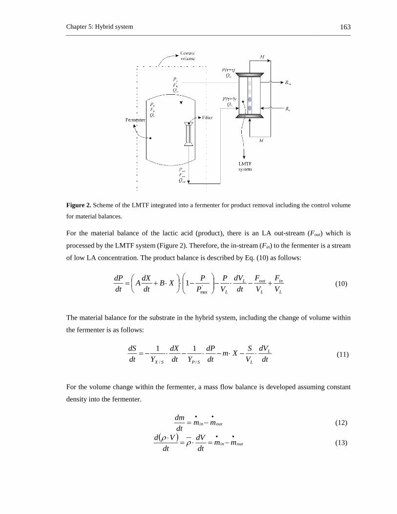
Chapter 5: Hybrid system 163
Figure 2. Scheme of the LMTF integrated into a fermenter for product removal including the control volume
for material balances.
For the material balance of the lactic acid (product), there is an LA out-stream (Fout) which is
processed by the LMTF system (Figure 2). Therefore, the in-stream (Fin) to the fermenter is a stream
of low LA concentration. The product balance is described by Eq. (10) as follows:
L
in
L
outL
L V
F
V
F
dt
dV
V
P
P
PXB
dt
dXA
dt
dP
'
max
1 (10)
The material balance for the substrate in the hybrid system, including the change of volume within
the fermenter is as follows:
dt
dV
V
SXm
dt
dP
Ydt
dX
Ydt
dS L
LSPSX
//
11 (11)
For the volume change within the fermenter, a mass flow balance is developed assuming constant
density into the fermenter.
outin mmdt
dm
(12)
outin mm
dt
dV
dt
Vd
(13)

164 Applications of a liquid membrane in Taylor flow regime (LMTF) on separation processes and
design of fermentation hybrid systems
outinL QQ
dt
dV (14)
QD can be assumed constant because this stream has a high water concentration, which makes the
change in volume due to LA removal negligible. Therefore, for simplification of the model for the
hybrid system, it can be assumed that the inlet volumetric flow of donor phase is the same as the
outlet volumetric flow of donor phase. Hence, Eq. (14) is equal to zero, and the model of the hybrid
system is reduced to:
max
1P
PX
dt
dX (15)
L
in
L
out
V
F
V
F
P
PXB
dt
dXA
dt
dP
'
max
1 (16)
Xmdt
dP
Ydt
dX
Ydt
dS
SPSX
//
11 (17)
From the control volume, three common variables can be identified for the shared streams between
the fermenter and the LMTF system.
inDout QQQ (18)
0 PPout (19)
PPin (20)
For calculation of the LA concentration in the stream that goes from the LMTF to the fermenter, the
model of the LMTF (Eq. (2)) is used. The OVMTC and the space-time are depending on the
operating conditions of the LMTF system.
outDDLin PakP )exp( , (21)
In Eq. (21) the outlet LA concentration from the fermenter (Pout) is the LA concentration at any point
of time within the fermenter provided by Eq. (16). The inlet and outlet mass flows of LA from the
fermenter are calculated through Eqs. (22) and (23), which involves the respective LA concentration
and the volumetric flow of the donor phase through the LMTF.

Chapter 5: Hybrid system 165
Doutout QPF (22)
Dinin QPF (23)
In order to increase the capacity of the LMTF, a multi-channel LMTF system is proposed. The
number of channels (Nch) within the LMTF system is included in Eqs. (22) and (23), yielding the
following equations:
chDoutout NQPF (22b)
chDinin NQPF (23b)
The hybrid system was modeled at the same initial conditions of the batch fermentation with a LMTF
system with one channel in order to compare both systems (batch and hybrid). For the LMTF the
operating conditions were selected that provide the maximum value of OVMTC with a suitable
space-time value. Then, the effect of the number of channels of the LMTF on the productivity, the
total mass of LA achieved and final biomass concentration was explored. Additionally, the effect of
the operating conditions of the LMTF (through the OVMTC) and the number of channels on the
final pH achieved within the fermenter was studied.
5.2.3 Experimental
Lactic acid batch fermentation by Lactobacillus casei ATCC 393
Fermentation was carried out with the lactic acid bacteria (LAB) Lactobacillus casei ATCC 393
(Microbiologics), and molecular toxicity of the components of the membrane phase on the LAB was
tested [6,7]. Pre-inoculum was prepared using two cryogenized pearls of the LAB within 25 mL of
MRS broth (Scharlau) into an incubator (RI 115, Binder) at 37 ºC. The inoculum was prepared at 37
ºC in 25 mL of the fermentation broth at 10 vol% of a culture of 24 h. The fermentation broth was
prepared at 10 g/L of tryptose (Scharlau), 20 g/L of dextrose anhydrous (Loba Chemie), 5 g/L of
sodium acetate (anhydrous, Merck), 2 g/L of ammonium citrate dibasic (Sigma-Aldrich), 0.2 g/L of
magnesium sulfate (Heptahydrate, Loba Chemie), 0.05 g/L of manganese sulfate (monohydrate,
Loba Chemie), and 2 g/L of potassium phosphate dibasic (anhydrous, Loba Chemie). Distilled water
was used for the preparation of the fermentation broth. A preparation of 500 mL sterile fermentation
broth was made.

166 Applications of a liquid membrane in Taylor flow regime (LMTF) on separation processes and
design of fermentation hybrid systems
The fermentation was carried out in a glass flask of 1 L (GL 45, Duran®) during 31.5 h. An incubator
(Binder™, ±0.1 K) was used to keep a constant temperature of 37 ºC along fermentation. Samples
of 3 mL were taken each 2 hours in order to measure cell growth (by dry cell weight method), lactic
acid and glucose (by HPLC). The pH (inoLab™, ±0.01) within the fermentation broth was measured
during each sampling. For HPLC (ELITE LaChrom) analysis, an ORH-801 column (Chrom Tech)
with a solution of 0.01 N H2SO4 (Merck, assay 95-97%) was used for the mobile phase, and a RI
detector at 45 °C.
5.2.4 Results and discussion
Liquid membrane in Taylor flow for LA removal
In the sensitivity analysis of the OVMTC in the range of variables described in Table 1, the
parameters of the OVMTC used for Eq. (3) were 1.6889, 0.5091, 0.1221, 2.7945, -0.0485, -1.3924
and, 0.0272 (α1 to α7). The calculation of the dimensionless numbers was carried out as shown in a
previous work [4].
Figure 3. Effect of Reynolds and relative velocity on overall volumetric mass transfer coefficient (OVMTC,
1/s) at a channel length of 348.8 cm, an inner diameter of the channel of 2.5 mm, a slug length of 4 cm and an
injected volume of the donor phase of 0.3436 cm3.
For Taylor flow, an increase of the droplet velocity increases the mass transfer through the interfaces
between the droplets (donor and receiving) and the continuous phase (membrane phase), because the
intensity of the internal circulations (within the slug and droplet) and the renewal velocity of the
liquid film (around droplets) also increase as the droplet velocity rises [22,23]. Internal mixing
provides homogenization of the solute concentration within the droplets and within the slug [24–28].
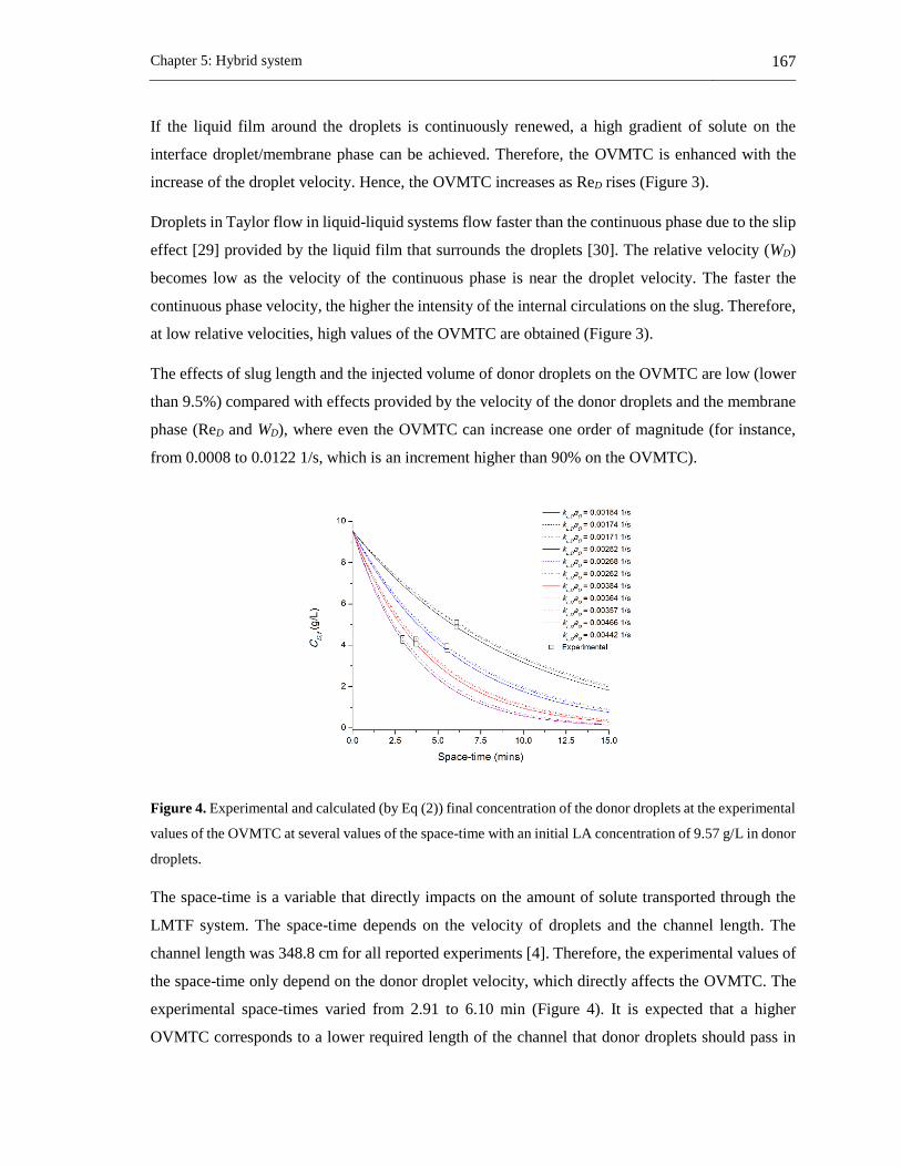
Chapter 5: Hybrid system 167
If the liquid film around the droplets is continuously renewed, a high gradient of solute on the
interface droplet/membrane phase can be achieved. Therefore, the OVMTC is enhanced with the
increase of the droplet velocity. Hence, the OVMTC increases as ReD rises (Figure 3).
Droplets in Taylor flow in liquid-liquid systems flow faster than the continuous phase due to the slip
effect [29] provided by the liquid film that surrounds the droplets [30]. The relative velocity (WD)
becomes low as the velocity of the continuous phase is near the droplet velocity. The faster the
continuous phase velocity, the higher the intensity of the internal circulations on the slug. Therefore,
at low relative velocities, high values of the OVMTC are obtained (Figure 3).
The effects of slug length and the injected volume of donor droplets on the OVMTC are low (lower
than 9.5%) compared with effects provided by the velocity of the donor droplets and the membrane
phase (ReD and WD), where even the OVMTC can increase one order of magnitude (for instance,
from 0.0008 to 0.0122 1/s, which is an increment higher than 90% on the OVMTC).
Figure 4. Experimental and calculated (by Eq (2)) final concentration of the donor droplets at the experimental
values of the OVMTC at several values of the space-time with an initial LA concentration of 9.57 g/L in donor
droplets.
The space-time is a variable that directly impacts on the amount of solute transported through the
LMTF system. The space-time depends on the velocity of droplets and the channel length. The
channel length was 348.8 cm for all reported experiments [4]. Therefore, the experimental values of
the space-time only depend on the donor droplet velocity, which directly affects the OVMTC. The
experimental space-times varied from 2.91 to 6.10 min (Figure 4). It is expected that a higher
OVMTC corresponds to a lower required length of the channel that donor droplets should pass in

168 Applications of a liquid membrane in Taylor flow regime (LMTF) on separation processes and
design of fermentation hybrid systems
order to achieve the maximum LA transport in the LMTF (Figure 4). Furthermore, when the droplet
has a low LA concentration, the effect of the space-time has a lower impact on the final LA
concentration than when the donor droplets has a high LA concentration. If there is a high LA
concentration in donor droplets, the driving force between donor droplets and the membrane phase
is high and thus low space-times are required. For the highest OVMTC achieved in the sensitivity
analysis (0.0122 1/s), 7 min is a sufficient space-time to achieve the highest LA transfer from donor
droplets.
Batch lactic acid fermentation
The fitted kinetic model is in agreement with the experimental data of the batch fermentation (Figure
5), achieving coefficients of the determination (r2) of 0.9973, 0.9956 and 0.9253 for glucose, lactic
acid (LA) and biomass, respectively. From the fitted kinetic parameters (Table 2), it can be observed
that the inhibitory LA concentration for production of LA and for cell growth is 13.94 and 14.49
g/L, respectively. In batch fermentation, when the LA concentration within the fermentation broth
is achieving the inhibitory LA concentration, the glucose consumption and biomass production tends
to cease. These occur in the pH range from 3.5 to 4.5.
Figure 5. Experimental data (symbols) and fitted kinetic model (continuous lines) of the batch lactic acid
fermentation by Lactobacillus casei ATCC 393 at 37 ºC during 31.5 h.
The batch lactic acid fermentation (Figure 5) shows that after 31.5 h of fermentation, glucose is still
available to convert to LA. However, by the inhibitory effect of the LA concentration within the
fermenter, the lactic acid bacteria cease the LA and biomass production at 25 h.

Chapter 5: Hybrid system 169
Table 2. Fitted kinetic parameters for the LA fermentation by Lactobacillus casei ATCC 393 at 37 ºC.
A 3.0061 g LA / g biomass
B 0.8994 g LA / g biomass·h
KS 18.2720 g/L
µmax 0.5215 1/h
Pmax 13.938 g/L
P’max 14.489 g/L
YP/S 1.8337 g LA / g glucose
YX/S 0.3227 g biomass / g
glucose
m 0.0431 g glucose / h·g
biomass
Integration of the LMTF with the lactic acid fermentation
The hybrid system was experimentally tested elsewhere [14] where all details can be shown. The
fermentation process was modeled using Eqs. (4)-(7) for the times in batch, and Eqs. (15)-(17) and
Eqs. (22)-(23) for the time of the hybrid process. The OVMTC was calculated by Eq. (3) from the
experimental operating conditions, giving a value of 0.0033 1/s. The model developed in this work
is in agreement with the experimental results (Figure 6) and the differences are analyzed below. The
model shows that the LA removal is slightly higher than experimental because LA removal in the
experiment was not strictly continuous. For the injection of the donor phase in the LMTF, a syringe
pump was used, which requires periods of times to reload the syringe with the filtered fermentation
broth. In the model, during the hybrid process, there is a continuous LA removal.
Figure 6. Experimental (symbols) and modeled (lines) batch-hybrid process during 22 h by using
Lactobacillus casei ATCC 393.

170 Applications of a liquid membrane in Taylor flow regime (LMTF) on separation processes and
design of fermentation hybrid systems
The experimental data show that glucose is consumed faster in the hybrid period than in the non-
hybrid period. However, this effect is not shown by the hybrid simulation. When the membrane
phase is in indirect contact with the Lactobacillus casei ATTC 393, due a toxic effect the glucose
consumption is promoted instead of the LA and biomass production [6,14]. This toxic effect is not
included in the model explaining the differences in glucose concentration. In addition, the final
biomass production is higher in the model than in the experiment due to the aforementioned
molecular toxic effect.
The effect of the integration of the LMTF with one or several channels to the batch LA fermentation
(of 50 mL) on the concentration profiles within fermenter was modeled by using Eqs. (15)-(17) and
(22b)-(23b). For the LMTF the highest OVMTC (0.0122 1/s) achieved from the sensitivity analysis
was used and the evaluation of the space-time (with a suitable space-time of 7 min) by Eq. (2), which
are achieving for the operating conditions shown in Table 3. The hybrid system was modeled until
full glucose consumption with LA removal through the LMTF with one channel from the beginning
of the fermentation.
Table 3. Conditions which maximize the value LA removal through the LMTF by the assessment of the
OVMTC and the space-time.
Variable Value
Lslug 4 cm
VD 0.3435 cm3
QD 0.4545 cm3/s
WD 0.1111
ReD 33.7491
CaD 0.0136
It can be observed that after 24.5 h of fermentation for the hybrid system (HS) there was a total
glucose consumption (Figure 7a) achieving productivities of 0.5275 and 3.2853 g/(L·h), for batch
and hybrid systems, respectively. The final biomass concentration was 1.9740 g/L for batch
fermentation, while for the hybrid system it was 4.6786 g/L (Figure 7a). In the hybrid system, the
rate of glucose consumption was practically constant as a function of fermentation time, which leads
to a reduced fermentation time as compared to the experimental batch fermentation.
Additionally, within the fermenter, the LA concentration was kept below 4 g/L and the pH between
5.9 and 6.2 using only one channel of LMTF (Figure 7b). The LA concentration is kept low within
the fermenter; the pH does not reach acidic conditions which are harmful to the lactic acid bacteria.

Chapter 5: Hybrid system 171
Figure 7. a) Profile of concentrations within the fermenter for the hybrid system (lines) at the best conditions
of the LMTF, compared to experimental batch fermentation (symbols). b) Comparison of the pH within
fermenter in hybrid (line) and batch (symbols) fermentations.
At acidic conditions, there is a high concentration of the undissociated LA, which is cytoplasmic
membrane soluble, and as a consequence of its presence within the bacteria, the cellular functions
are disabled [31]. This produces a failure in the proton motive forces of the cell [32]. Since the acidic
condition within the fermenter was avoided by LA removal by LMTF, the lactic acid bacteria are
not product inhibited, which allows for a normal glucose consumption to convert it in lactic acid,
and keep the cell growth. Thus, the LA removal from the fermenter promotes glucose consumption,
LA production, and cell growth.
The rate of LA removal in the hybrid system with one channel (Figure 8) was low from 0 to 5 h,
because at this period of time, the driving-force for LA removal in the LMTF was low (Figure 7a).
For times between 5 h and 20 h, the LA removal rate increases monotonically according to the
increase of LA concentration within the fermenter and thus, the driving-force for LA removal.
Hence, the rate of LA removal is proportional to the driving-force, but how close it is to the rate of
LA production will be limited by the number of channels used in the LMTF system.
In spite of the similar rates of LA removal and LA production by using a LMTF with one channel
(Figure 8), one more channel can be added to the LMTF to increase the rate of LA removal, reducing
the fermentation time and increasing the productivity. However, the maximum rate of LA removal

172 Applications of a liquid membrane in Taylor flow regime (LMTF) on separation processes and
design of fermentation hybrid systems
that can be achieved is restricted by the rate of LA production, no matter if more channels of the
LMTF are added. At this condition the LA concentration within the fermenter will be approximately
constant. Hence, the main effect of increasing the number of channels of the LMTF for this volume
of fermentation is on LA productivity and on LA concentration within the fermenter.
Figure 8. LA rates (removed and produced) of the hybrid system of the LMTF at the better conditions for the
LMTF with one channel.
Figure 9. Effect of the number of channels on productivity (continuous line), the total mass of LA achieved
(dash line), final biomass concentration (dot line) and required time for fully consumption of glucose (short
dash-dot line) of the hybrid system for a batch fermentation of 50 mL.

Chapter 5: Hybrid system 173
Figure 9 shows that increasing the number of channels from 0 (conventional batch fermentation) to
4 reduces the fermentation time for total glucose consumption from 70 to 21.9 h, and the productivity
increases from 0.2063 to 4.32 g/(L·h). For a number of channels higher than 4, there are no important
changes on productivity, final mass of LA achieved, final concentration of biomass or the
fermentation time. From these results, it can be observed that for every 50 mL of this fermentation
broth, 4 channels are required in the LMTF using the best operating conditions of the LMTF based
on OVMTC.
The removal of LA from the fermenter through the LMTF can also be useful to control the pH within
the fermenter. It can be observed that the final value of the pH within the fermenter can be tuned by
both varying the operating conditions and by the number of channels used in the LMTF (Figure 10).
The LA fermentation has an optimal pH to the production of LA and biomass [33–35], therefore, the
operating conditions and the number of channels of the LMTF, can be set according to required pH
of the LA bacteria.
Figure 10. Effect of the OVMTC and number of channels of the LMTF on the final pH within the fermenter
of 50 mL of fermentation broth.
In order to increase productivity, and the achieved values of the final biomass and LA concentrations,
other schemes of the fermentation can be explored, for instance, a fed-batch fermentation integrated
to a LMTF for LA removal. Although the LAB Lactobacillus casei ATCC 393 is inhibited at low
LA concentrations it was possible to reduce the end-product inhibition opening the window to
explore a continuous fermentation integrated with the LMTF. For this continuous fermentation,
usually high biomass and substrate concentrations are used, in order to achieve high rates of
consumption and production in the fermentation. However, some LAB does not tolerate high
174 Applications of a liquid membrane in Taylor flow regime (LMTF) on separation processes and
design of fermentation hybrid systems
substrate concentrations. An interesting advantage to explore by LA removal of a continuous or
semi-continuous fermentation is that even when working at low substrate concentrations it is
possible to achieve high consumption and production rates if the substrate is fed in different periods
of time or in continuous and the LA is continuously removed by the LMTF. An economic study can
be made in order to study the impact of applying these schemes or similar ones on the total cost of
the process. For this cost analysis is important to include the toxic effect of the membrane phase on
the lactic acid bacteria.
5.2.5 Conclusions
A model to describe a hybrid system of lactic acid removal by a LMTF from a fermentation broth
was developed using a previous model of a LMTF and a kinetic model of a LA fermentation, which
was fitted to experimental data of a batch fermentation. The model turns out to be in agreement to
experimental data of the hybrid system and differences are due to toxicity effects that the model does
not take into account. Using this model for the hybrid system, a range of operating conditions is
recommended to increase the performance for LA production.
A high OVMTC of the LMTF for LA removal can be achieved at low relative velocities, high
Reynolds, low injected volumes of donor phase and low slug lengths. However, the velocity of
droplets and the membrane phase, which are involved in the relative velocity, are the main factors
on the OVMTC.
By modeling the hybrid proposed system, it is possible to achieve low lactic acid concentration
within the fermenter avoiding the acidic condition that negatively affects the lactic acid bacteria.
Therefore, an enhancement of the productivity and the produced biomass is achieved. It was
observed that at the modeling conditions, for each 50 mL of the fermentation broth 4 channels of the
LMTF are required operating with the highest OVMTC of the LMTF. Additionally, the LMTF also
can be used as a control system for the pH within the fermenter by tuning the operating conditions
and the number of channels of the LMTF, in order to keep the pH at an optimum value within the
fermenter according to the bacteria or strain used.
The fermentation time until total glucose consumption for a hybrid LMTF – fermentation system is
reduced 3.19 times, while the LA productivity of the batch fermentation is increased 20.9 times as
compared to a conventional batch fermentation.

Chapter 5: Hybrid system 175
NOTATION
A Growth associate constant rate (g lactic acid/g biomass)
a Specific surface area (m2/m3)
B Non-growth associate constant rate (g lactic acid/(g biomass·h))
C Concentration of solute (g/L)
Ca Capillary number
d Inner diameter of the channel (m)
F Lactic acid mass flow (g/h)
J Flux of solute (g/(L·s))
KS Monod constant (g/L)
kLa Overall volumetric mass transfer coefficient (1/s)
Lch Channel length (m)
m Coefficient of maintenance (g glucose/(g biomass·h))
Nch Number of channels in the LMTF
n Number of experimental data
P Lactic acid (product) concentration (g/L)
Pmax Lactic acid concentration above which bacteria do not grow (g/L)
P’max Lactic acid concentration above which bacteria cease lactic acid production (g/L)
Q Volumetric flow rate (m3/s)
Re Reynolds number
S Glucose (substrate) concentration (g/L)
t Time (s)
U Droplet velocity (m/s)
VL Fermenter volume (m3)
W Relative velocity
X Biomass concentration (g/L)
YX/S Biomass yield on the utilized substrate (g biomass/g glucose)
YP/S Product yield on the utilized substrate (g lactic acid/g glucose)
α Fitted parameter for calculation of the mass transfer coefficient
τ Space-time (s)
µ Specific growth rate (1/h)
Subscripts and superscripts
calc Calculated data
D Donor phase
eq In equilibrium
exp Experimental data
in Input stream
inj Injection
max maximum
out Output stream
slug Slug
T Total

176 Applications of a liquid membrane in Taylor flow regime (LMTF) on separation processes and
design of fermentation hybrid systems
5.2.6 References
[1] R.D. Noble, S.A. Stern, Membrane Separations Technology: Principles and Applications, 3rd
ed., Elsevier, Amsterdan, 2003.
[2] V.S. Kislik, Liquid Membranes Principles & Applications in Chemical Separation &
Wastewater Treatment, 1st ed., Elsevier B.V., Amsterdan, 2010.
[3] A.D. Pérez, J. Fontalvo, A new concept of liquid membranes in Taylor flow: performance
for lactic acid removal, Chem. Eng. Process. - Process Intensif. (2019).
[4] A.D. Pérez, B. Van der Bruggen, J. Fontalvo, Study of overall mass transfer coefficients in a
liquid membrane in Taylor flow regime: Calculation and correlation, Chem. Eng. Process. -
Process Intensif. 134 (2018) 20–27.
[5] J.A. Moulijn, A. Stankiewicz, J. Grievink, A. Górak, Process intensification and process
systems engineering: A friendly symbiosis, Comput. Chem. Eng. 32 (2008) 3–11.
[6] A.D. Pérez, V.M. Gómez, S. Rodríguez-Barona, J. Fontalvo, Liquid-liquid Equilibrium and
Molecular Toxicity of Active and Inert diluents of the Organic Mixture Tri-iso-
octylamine/Dodecanol/Dodecane as Potential Membrane Phase for Lactic Acid Removal, J.
Chem. Eng. Data. submited (2019).
[7] A.D. Pérez, S. Rodríguez-Barona, J. Fontalvo, Molecular toxicity of potential liquid
membranes for lactic acid removal from fermentation broths using Lactobacillus casei ATCC
393, Dyna. 85 (2018) 360–366. doi:10.15446/dyna.v85n207.72374.
[8] A. Komesu, M.R. Wolf Maciel, R. Maciel Filho, Separation and Purification Technologies
for Lactic Acid – A Brief Review, BioResources. 12 (2017) 6885–6901.
doi:10.15376/biores.12.3.6885-6901.
[9] J. Vijayakumar, R. Aravindand, T. Viruthagiri, Recent Trends in the Production, Purification
and Application of Lactic Acid, Chem. Biochem. Eng. Q. 22 (2008) 245–264.
https://hrcak.srce.hr/24811.
[10] C. Miller, A. Fosmer, B. Rush, T. McMullin, D. Beacom, P. Suominen, Industrial Production
of Lactic Acid, in: Ref. Modul. Life Sci., Elsevier, 2017: pp. 179–188. doi:10.1016/B978-0-
12-809633-8.09142-1.
[11] M. Singhvi, T. Zendo, K. Sonomoto, Free lactic acid production under acidic conditions by

Chapter 5: Hybrid system 177
lactic acid bacteria strains: challenges and future prospects, Appl. Microbiol. Biotechnol. 102
(2018) 5911–5924. doi:10.1007/s00253-018-9092-4.
[12] K.L. Wasewar, A.A. Yawalkar, J.A. Moulijn, V.G. Pangarkar, Fermentation of Glucose to
Lactic Acid Coupled with Reactive Extraction: A Review, Ind. Eng. Chem. Res. 43 (2004)
5969–5982. doi:10.1021/ie049963n.
[13] N. Tik, E. Bayraktar, Ül. Mehmetoglu, In situ reactive extraction of lactic acid from
fermentation media, J. Chem. Technol. Biotechnol. 76 (2001) 764–768.
[14] A.D. Pérez, S. Rodríguez-Barona, J. Fontalvo, Integration of a liquid membrane in Taylor
flow regime with a fermentation by Lactobacillus casei ATCC 393 for in-situ lactic acid
removal, Chem. Eng. Process. - Process Intensif. submited (2019).
[15] J. Fontalvo, A.D. Pérez, Membrana Líquida y proceso para realizarlo, Rad. 15-131023, n.d.
[16] Y. Okubo, T. Maki, N. Aoki, T. Hong Khoo, Y. Ohmukai, K. Mae, Liquid-liquid extraction
for efficient synthesis and separation by utilizing micro spaces, Chem. Eng. Sci. 63 (2008)
4070–4077. doi:10.1016/j.ces.2008.05.017.
[17] M. Sattari-Najafabadi, M.N. Nasr Esfahany, Intensification of liquid-liquid mass transfer in
a circular microchannel in the presence of sodium dodecyl sulfate, Chem. Eng. Process.
Process Intensif. 117 (2017) 9–17.
[18] D. Liu, K. Wang, Y. Wang, Y. Wang, G. Luo, A simple online phase separator for the
microfluidic mass transfer studies, Chem. Eng. J. 325 (2017) 342–349.
[19] M. Sattari-Najafabadi, M. Nasr Esfahany, Z. Wu, B. Sundén, Hydrodynamics and mass
transfer in liquid-liquid non-circular microchannels: Comparison of two aspect ratios and
three junction structures, Chem. Eng. J. 322 (2017) 328–338.
[20] Susanti, J.G.M. Winkelman, B. Schuur, H.J. Heeres, J. Yue, Lactic Acid Extraction and Mass
Transfer Characteristics in Slug Flow Capillary Microreactors, Ind. Eng. Chem. Res. 55
(2016) 4691–4702.
[21] M. Monteagudo, Lourdes, J. Rincón, J. Fuertes, Kinetics of Lactic Acid Fermentation by
Lactobacillus delbrueckii Grown on Beet Molasses, J. Chem. Technol. Biotechnol. 68 (1997)
271–276.
[22] M.N. Kashid, D.W. Agar, S. Turek, CFD modelling of mass transfer with and without
178 Applications of a liquid membrane in Taylor flow regime (LMTF) on separation processes and
design of fermentation hybrid systems
chemical reaction in the liquid-liquid slug flow microreactor, Chem. Eng. Sci. 62 (2007)
5102–5109.
[23] N. Aoki, S. Tanigawa, K. Mae, A new index for precise design and advanced operation of
mass transfer in slug flow, Chem. Eng. J. 167 (2011) 651–656.
[24] R. Gupta, S.S.Y. Leung, R. Manica, D.F. Fletcher, B.S. Haynes, Hydrodynamics of liquid–
liquid Taylor flow in microchannels, Chem. Eng. Sci. 92 (2013) 180–189.
[25] H.L. Goldsmith, S.G. Mason, The flow suspensions through tubes. II. Single large bubbles,
J. Coloid Sci. 18 (1963) 237–261.
[26] G.I. Taylor, Deposition of a viscous fluid on a plane surface, J. Fluid Mech. 9 (1961) 218.
[27] T.C. Thulasidas, M.A. Abraham, R.L. Cerro, Flow patterns in liquid slugs during bubble-
train flow inside capillaries, Chem. Eng. Sci. 52 (1997) 2947–2962.
[28] T. Taha, Z.F. Cui, Hydrodynamics of slug flow inside capillaries, Chem. Eng. Sci. 59 (2004)
1181–1190.
[29] W.O. Smith, M.D. Crane, The jamin effect in cylindrical tubes, J. Am. Chem. Soc. 52 (1930)
1345–1349.
[30] F. Fairbrother, A.E. Stubbs, Studies in electro-endosmosis. Part VI. The “bubble-tube”
method of measurement, J. Chem. Soc. (1935) 527.
[31] M. Othman, A.B. Ariff, L. Rios-Solis, M. Halim, Extractive Fermentation of Lactic Acid in
Lactic Acid Bacteria Cultivation: A Review, Front. Microbiol. 8 (2017) 1–7.
doi:10.3389/fmicb.2017.02285.
[32] L.M.D. Gonçalves, A. Ramos, J.S. Almeida, A.M.R.B. Xavier, M.J.T. Carrondo, Elucidation
of the mechanism of lactic acid growth inhibition and production in batch cultures of
Lactobacillus rhamnosus, Appl. Microbiol. Biotechnol. 48 (1997) 346–350.
doi:10.1007/s002530051060.
[33] P. Pal, J. Sikder, S. Roy, L. Giorno, Process intensification in lactic acid production: A review
of membrane based processes, Chem. Eng. Process. Process Intensif. 48 (2009) 1549–1559.
[34] C.N. Burgos-Rubio, M.R. Okos, P.C. Wankat, Kinetic study of the conversion of different
substrates to lactic acid using Lactobacillus bulgaricus, Biotechnol. Prog. 16 (2000) 305–314.
Chapter 5: Hybrid system 179
doi:10.1021/bp000022p.
[35] A.D. Nandasana, S. Kumar, Kinetic modeling of lactic acid production from molasses using
Enterococcus faecalis RKY1, Biochem. Eng. J. 38 (2008) 277–284.
doi:10.1016/j.bej.2007.07.014.

180 Applications of a liquid membrane in Taylor flow regime (LMTF) on separation processes and
design of fermentation hybrid systems
Chapter 6: General conclusions and perspectives 181
6. Chapter 6: General conclusions and perspectives
6.1 Major findings
6.1.1 Liquid-liquid equilibria
The liquid-liquid equilibria (LLE) of organic mixtures of trioctylamine (TiOA) in dodecanol (at 37
vol% of TOA), tri-iso-octylamine (TiOA) in dodecanol (at 10 vol% of TiOA), TiOA in dodecane (at
10 vol% of TiOA) and TiOA in dodecanol/dodecane (at 10 vol% of TiOA and 40 vol% of dodecanol)
with lactic acid (LA) aqueous solutions were experimentally measured and the LA distribution
coefficient and LA chemical equilibrium constant were fitted through a proposed model. The tertiary
amines react with LA to produce an acid-amine complex, and the diluents (dodecanol and dodecane)
allow the solubilization of the free LA on the organic phase. On the other hand, dodecanol provides
a solvation shell to the acid-amine complex to stabilize it. Therefore, the LA in the organic phase in
equilibrium can be as free LA or as an acid-amine complex. However, most of the amount of LA in
the organic phase in equilibrium is due to the chemical reaction which is in agreement with the results
of the chemical equilibrium constant and distribution coefficients of the tested systems in this
dissertation. For all tested systems, the distribution coefficient is around 0.01 and 0.26, while the
chemical equilibrium is around 34 to 437 L/mol.
The organic mixture that provides a high LA concentration in the organic phase is TiOA in
dodecanol. On the contrary, the organic mixture that provides the poorer LA concentration in the
organic phase is TiOA in dodecane. Dodecanol is able to solvate the acid-amine complex, while
dodecane does not provide solvation of the acid-amine complex. On the other hand, the mixtures
TOA in dodecanol and TiOA in dodecanol/dodecane achieve similar values of the chemical
equilibrium constant.

182 Applications of a liquid membrane in Taylor flow regime (LMTF) on separation processes and
design of fermentation hybrid systems
6.1.2 Molecular toxicity test combined with liquid-liquid equilibria
assessments for a membrane phase selection
The tertiary amines in alcohols have shown enough capacity to receive the LA based on experimental
results in this work and in the available scientific literature. However, generally, the solvents (for
liquid-liquid extraction) and the membrane phases (for liquid membranes) with high capacity to LA
removal are toxic to the lactic acid bacteria (LAB). However, the level of toxicity depends on the
kind of microorganism and strain used. Hence, these solvents can be mixed with other organic
compounds that reduce the toxic effect on the specific microorganism but also they can reduce the
removal capacity. Liquid-liquid equilibrium is more critical for liquid extraction than for liquid
membranes because with membranes the steps of extraction and solvent regeneration take place at
the same time and thus the solvent bulk concentration is far from equilibrium.
In this thesis, the molecular toxicity of TOA, TiOA, Aliquat 336 (all of them are carriers), dodecane,
dodecanol, and oleyl alcohol (all of them are diluents) on the LAB Lactobacillus casei ATCC 393
was experimentally measured (organic compounds with the potential to comprise membrane phase
for LA removal). All carriers, tested are toxic on the LAB, following the next order of toxicity:
Aliquat 336 > TOA > TiOA. For the diluents, the dodecanol is toxic, the oleyl alcohol is medium
toxic and dodecane is non-toxic on the LAB. Also the molecular toxicity of TOA and TiOA at 10,
20 and 30 vol% in dodecane on the LAB was tested, showing that these tertiary amines at 10 vol%
are non-toxic on the LAB, at 20 vol% they are medium toxic (being TiOA less toxic than TOA) and
at 30 vol% the TiOA keeps medium toxic and the TiOA becomes toxic.
Then, the molecular toxicity and the LLE of TiOA at 10 vol% on dodecane and dodecanol at several
concentrations of dodecanol (from 0 to 90 vol%) were experimentally tested. The mixture at 90 vol%
of dodecanol (mixture TiOA/dodecanol) has higher values of distribution coefficient and chemical
equilibrium constant than the mixture at 0 vol% of dodecanol (TiOA/dodecane), while the mixture
TiOA/dodecanol is toxic and the mixture TiOA/dodecane is non-toxic on the LAB. Both, the
molecular toxicity and the chemical equilibrium constant, for the dodecanol concentrations from 10
to 50 vol%, increases as dodecanol concentration rises. The mixture TiOA/dodecanol/dodecane at
dodecanol proportions between 30 to 40 vol% shows a good compromise between a high value of
the chemical equilibrium constant and a relatively low molecular toxicity.
An interesting finding of this study is the response of the LAB to the presence of the organic phases
TiOA/dodecane and TiOA/dodecanol within the fermentation broth. The cell growth is promoted
instead glucose consumption when the mixture TiOA/dodecane is within the fermentation broth,

Chapter 6: General conclusions and perspectives 183
while the glucose consumption is promoted instead cell growth when the organic mixture
TiOA/dodecanol is within the fermentation broth. Even, for all mixtures TiOA/dodecanol/dodecane
the last behavior persists, regardless of the presence of dodecane within the respective organic
mixture.
6.1.3 Liquid membrane in Taylor flow
Removal of LA was used as a proof of concept of the liquid membrane in Taylor flow (LMTF). The
LA removal level was experimentally measured through the degree of LA removal that is defined as
the ratio between the amount of LA removed from donor phase and the total amount of LA acid that
theoretically can be accepted in the receiving phase. According to experimental results, the degree
of LA removal shows a dependency on the driving force of LA concentrations between donor
droplets and membrane interface and the space-time of the phases within the channel. The maximum
possible levels for the degree of LA removal are providing by low injection times of the dispersed
phases and high droplet velocities in an optimal value of the slug length.
Additionally, the overall volumetric mass transfer coefficients (OVMTC) were calculated from the
experimental results and a semi-empirical model was developed and fitted for the calculation of the
OVMTC. The variables that most affect the value of the OVMTC are the donor droplet and
membrane velocities, and the injection time, which are in agreement with the findings of the proof
of concept of the LMTF.
The results show that the LMTF preserves the advantages of conventional emulsion liquid
membranes while overcomes the stability problems of emulsion systems. Hence, the LMTF is a
promising technology for industrial applications which can be integrated to other separation or
reactive processes to enhance them by applying the intensification process philosophy.
6.1.4 Hybrid system of a LMTF integrated with a LA fermentation
The hybrid system was experimentally tested by integrating the LMTF for LA removal (using a
membrane phase composed by TiOA/dodecanol/dodecane) with a LA fermentation with
Lactobacillus casei ATCC 393. Through the hybrid system, it is possible to increase the biomass
production and LA productivity by 12 and 41.8%, respectively, as compared to a conventional batch
fermentation. However, the yields of LA to glucose and biomass to glucose are lower in the hybrid
system as compared with the batch system. Due to molecular toxicity on the bacteria, glucose
consumption is enhanced instead LA and biomass production.

184 Applications of a liquid membrane in Taylor flow regime (LMTF) on separation processes and
design of fermentation hybrid systems
A mathematical model that describes the hybrid system was developed using experimental data of
conventional batch fermentation and the OVMTC model. The model for the hybrid system shows
good agreement with experimental data of a hybrid system. However, there are some differences,
especially on glucose concentration, due to the model does not take into account molecular toxicity.
The model also includes the number of channels of a multi-channel LMTF. The impact of the multi-
channel system on the LA productivity and biomass production are analyzed, showing that the end-
product inhibition on the LA fermentation can be controlled by LA removal through the LMTF.
Additionally, the LMTF is shown and proposed as a control system of the pH within the fermentation
broth, which can optimize the LA production.
6.2 Perspectives
6.2.1 Scale up: Multi-channel system and phase separation in the LMTF
An interesting following step of this research is on developing of a new prototype of the LMTF
including several channels in order to increase the capacity to process the donor phase through the
LMTF. By a multi-channel LMTF prototype, the impact of the integration of this LMTF with any
fermentation process will be higher, the productivity and yields may have a successful impact on the
economy of fermentation processes. On the other hand, it encourages the study of continuous hybrid
processes by integration of a LMTF with multi-channels with several kinds of fermentations.
The developing of a new prototype of the LMTF, requires the design of an automatic system for
phase separation (donor from the membrane and receiving from membrane) at the outlet of the
channel. It can be carried out by applying the interaction of hydrophobic or hydrophilic surfaces
which can interact with the phases of the LMTF in order to separate each other. Currently, a master-
thesis in our research group (Applications of New Technology Research Group, ANTGR) that
explores the spatial location of the channels, the angle of contact between the phases and the
interaction between the surfaces of channel walls with the phases was carried. It explored both
experimental and CFD (Computational Fluid Dynamics) results for the involved phases of the
current LMTF for LA removal. The results are promising, as regards it is possible to separate these
phases by the interaction between the surface of the channel walls and the involved phases (donor,
receiving and membrane). The phase separation applying the aforementioned concept of the affinity
of the phases with the surface of the walls also has been studied for other researchers showing a
promising method for phase separation in two-phase systems.

Chapter 6: General conclusions and perspectives 185
Other alternative for phase separation is to use a timer for the injected donor and receiving phases.
A timer can be integrated to solenoid valves and Y-divisors (or T-divisor), in order to drive the train
of donor droplets with the membrane phase for one side of the divisor, and the train of receiving
droplets with the membrane phase for the other side of the divisor. This kind of system has to be
design for modules of hundreds or thousands of channels of the LMTF prototype.
6.2.2 Modeling of the LMTF by CFD
Modeling of the hydrodynamics and mass transport by CFD is an important complementary study
to carry out for a deep understanding of the involved phenomena in solute transport by the LMTF
system. In our research group a master-thesis on this field is currently carrying out. It involves
modeling of the hydrodynamics and the mass transport through the droplets of the LMTF for LA
removal by using the same phases than this thesis. A wide range of operating conditions can be
explored achieving detailed and microscopic results that can be compared with the current
experimental results.
6.2.3 Supported liquid membrane in multiphase flow
The concept of the LMTF can be extended to the conventional supported liquid membrane (SLM).
The SLM is classified as a perstraction method without phase dispersion. However, the SLM can
become in a perstraction method with phase dispersion by using tubular supports in a double-tube
system in Taylor flow. The tubular porous support has to be located within of another tube. The
porous of the support has to be filled with the membrane phase by the conventional techniques for
that. For the inner section of the support, the membrane phase flows as a continuous phase while the
donor phase flows as donor droplets. At the outside of the inner section, the donor phase can be
separated from membrane phase by the technique of the affinity of the liquid with the wall surfaces
or by a decanter (Figure 1). For the annular section (section between the tube walls and the external
surface of the support) the membrane phase that is separated from the donor phase flows as
continuous phase in the annuli in counter-flow (for higher driving force of solute removal) while the
receiving phase can travel as annuli Taylor droplets or any another kind of dispersed phase of two-
phase flows regime, such as, dropply/bubbly, stratified or churn flows. At the outside of the annular
section, both phases (receiving from membrane) can be separated by the same technique used for the
inner section, and the membrane phase must be fed into the inner section in order to stay recirculating
continuously the membrane phase in both section of the system. In this process, called supported
liquid membrane in multiphase flow (SLMMPF) the solute is transported from the donor droplets to
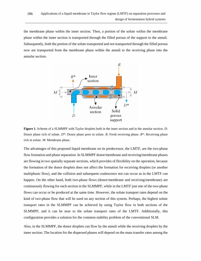
186 Applications of a liquid membrane in Taylor flow regime (LMTF) on separation processes and
design of fermentation hybrid systems
the membrane phase within the inner section. Then, a portion of the solute within the membrane
phase within the inner section is transported through the filled porous of the support to the annuli.
Subsequently, both the portion of the solute transported and not transported through the filled porous
now are transported from the membrane phase within the annuli to the receiving phase into the
annular section.
Figure 1. Scheme of a SLMMPF with Taylor droplets both in the inner section and in the annular section. D:
Donor phase rich of solute. D*: Donor phase poor in solute. R: Fresh receiving phase. R*: Receiving phase
rich in solute. M: Membrane phase.
The advantages of this proposed liquid membrane on its predecessor, the LMTF, are the two-phase
flow formation and phase separation. In SLMMPF donor/membrane and receiving/membrane phases
are flowing in two spatially separate sections, which provides of flexibility on the operation, because
the formation of the donor droplets does not affect the formation for receiving droplets (or another
multiphasic flow), and the collision and subsequent coalescence not can occur as in the LMTF can
happen. On the other hand, both two-phase flows (donor/membrane and receiving/membrane) are
continuously flowing for each section in the SLMMPF, while in the LMTF just one of the two-phase
flows can occur or be produced at the same time. However, the solute transport rates depend on the
kind of two-phase flow that will be used on any section of this system. Perhaps, the highest solute
transport rates in the SLMMPF can be achieved by using Taylor flow in both sections of the
SLMMPF, and it can be near to the solute transport rates of the LMTF. Additionally, this
configuration provides a solution for the common stability problem of the conventional SLM.
Also, in the SLMMPF, the donor droplets can flow by the annuli while the receiving droplets by the
inner section. The location for the dispersed phases will depend on the mass transfer rates among the

Chapter 6: General conclusions and perspectives 187
phases. In theory, the phase (donor or receiving) which provides of the lower transfer rate (taking
into account the kind of two-phase flow used) must be located in the inner section in order to produce
Taylor droplets and take advantage of the features of mass transport of this kind of two-phase flow.
The absorption process (gas-liquid), such as the CO2 recovery in a donor phase, also can be explored
both the SLMMPF and the LMTF. There are several configurations to explore in this new proposed
technology.
6.2.4 Possible industrial applications
The receiving phase and the membrane phase synthetized in for this work can be used for removal
of other organic acids, such as citric, acetic, malic and butyric, among others. Also, on another
fermentation process such as ethanol or ABE fermentation. For both fermentative processes, liquid-
liquid extraction has been studied for the specific metabolite removal. Therefore, there are available
membrane and receiving phases for it.
Another interesting field for the LMTF by using tri-iso-octylamine as the carrier within the
membrane phase is the removal of some heavy metals from effluents, such as cadmium, chromium,
cobalt, and lithium, where the conventional liquid membranes already are involved.
The window of applications for the LMTF process is wide. In theory, every single liquid-liquid
extraction process or liquid membrane process can become in a LMTF process. Then, there are
several fields to explore by using this promising membrane technology. For instance, applications
in process that involve equilibrium chemical reactions (in the liquid phase) in order to remove one
of the products and drive the reaction in the desired direction (by Le Chatelier’s principle), or for
enzymatic reactions which require the removal of the product. One example is the esterification
reactions, where the ester production can be promoted by water or the ester removal (any product of
the reaction). The challenge of these applications is in to find the suitable membrane and receiving
phases for the specific solute removal.
188 Applications of a liquid membrane in Taylor flow regime (LMTF) on separation processes and
design of fermentation hybrid systems

List of Scientific Contributions
Articles published in peer-reviewed academic journals
Alan D. Perez, Sneyder Rodríguez-Barona, Javier Fontalvo, Liquid-liquid equilibria for
trioctylamine/1-dodecanol/lactic acid/water system at 306.1, 310.1, and 316.1 K:
Experimental data and prediction, J Chem. Eng. Data 61 (2016) 2269−2276.
Alan D. Pérez, Bart Van der Bruggen, Javier Fontalvo, Study of overall mass transfer
coefficients in a liquid membrane in Taylor flow regime: Calculation and correlation, Chem.
Eng. Process. - Process Intensif 134 (2018) 20–27.
Alan D. Pérez, Sneyder Rodríguez-Barona, Javier Fontalvo, Molecular toxicity of potential
liquid membranes for lactic acid removal from fermentation broths using Lactobacillus casei
ATCC 393, DYNA, 85(207), pp. 360-366, Octubre - Diciembre, 2018.
Alan D. Pérez, Sneyder Rodríguez-Barona, Javier Fontalvo, Liquid−liquid equilibria of
lactic acid/water solutions in tri-iso-octylamine/dodecane/1-dodecanol at 306.1, 310.1, and
316.1 K. Experimental data and prediction, J. Chem. Eng. Data, 2019, 64 (2), 603–610
A.D. Pérez, J. Fontalvo, A new concept of liquid membranes in Taylor flow: performance
for lactic acid removal, Chem. Eng. Process. - Process Intensif 139 (2019) 95–102
A.D. Pérez, V.M. Gómez, S. Rodríguez-Barona, J. Fontalvo, Liquid-liquid equilibrium and
molecular toxicity of active and inert diluents of the organic mixture tri-iso-
octylamine/dodecanol/dodecane as potential membrane phase for lactic acid removal, J.
Chem. Eng. Data. Article ASAP.
A.D. Pérez, J. Fontalvo, Integration of a liquid membrane in Taylor flow regime with a
fermentation by Lactobacillus casei ATCC 393 for in-situ lactic acid removal, Chem. Eng.
Process. - Process Intensif. 140 (2019) 85–90.
Articles submitted in peer-reviewed academic journals

190 Applications of a liquid membrane in Taylor flow regime (LMTF) on separation processes and
design of fermentation hybrid systems
Alan D. Pérez, Bart Van der Bruggen, Javier Fontalvo, Modeling of a liquid membrane in
Taylor flow integrated with lactic acid fermentation, Chem. Eng. Process. - Process Intensif.
submited.
Contributions to scientific conferences
10th European Congress of Chemical Engineering, Nice - France, September 27th to
October 1st, 2015. A liquid membrane process using a Taylor flow regime – Oral
presentation.
Congreso Colombiano de Ingeniería Química y Profesiones Afines, Manizales - Colombia,
18 - 20 de octubre, 2017. Evaluación de un sistema híbrido de fermentación integrado a una
membrana líquida en flujo de Taylor para la recuperación de ácido cítrico – Poster.
Congreso Colombiano de Ingeniería Química y Profesiones Afines, Manizales - Colombia,
18 - 20 de octubre, 2017. Evaluación de la toxicidad de solventes orgánicos en bacterias
probióticas - Poster.
Congreso Colombiano de Ingeniería Química y Profesiones Afines, Manizales - Colombia,
18 - 20 de octubre, 2017. Separación de ácido láctico a través de una membrana líquida en
flujo de Taylor – Oral presentation.
Euromembrane, Valencia - Spain, 9 - 13 July, 2018. Liquid membrane in Taylor flow
regime: Lactic acid removal. Poster.
International awards
Best poster presentation award: Euromembrane 2018, Valencia – Spain, 9 – 13 July.

About the author
Alan Didier Pérez Ávila was born in Bogotá, Colombia in 1985. He earned his B.Sc. and M.Sc. in
Chemical Engineering in the National University of Colombia, Manizales-Colombia. He is a
member of the research group of application of new technologies since 2011. He was the technical
laboratory coordinator in the laboratory of process intensification and hybrid systems (2014-2017).
He was a teacher of kinetic and catalysis and teaching assistant in heat and transfer processes, both
at National University of Colombia, Manizales-Colombia, in 2013 and 2014, respectively.
His research has focused on process intensification, working in the development and integration of
membrane technology with fermentation processes. During his M.Sc. and Ph.D. studies, he has
worked in developing a new kind of contact in liquid membranes by using the Taylor flow regime,
under the supervision of Professor Javier Fontalvo. His Ph.D. internship was in the ProcESS division
of KU Leuven, Belgium. Here, he worked under the supervision of Professor Bart Van der Bruggen
as a guest researcher. During his internship, he works in developing a model for the liquid membrane
in Taylor flow (LMTF) and for a hybrid system where the LMTF is involved. He is a member of the
European Membrane Society since 2018.
ORCID: 0000-0001-7896-0130


Recommended