AUTOMATIC LIGHTING SYSTEM FOR CHILDREN
Cheong Yew Wai
BEKM
APRIL 2009

i
“I hereby declared that I have read through this report and found that it has
comply the partial fulfillment for awarding the degree of Bachelor of Electrical Engineering
(Mechatronic)”
Signature :
Supervisor’s name : Pn. Ainain Nur binti Hanafi
Date : 22 April 2009
ii
AUTOMATIC LIGHTING SYSTEM FOR CHILDREN
CHEONG YEW WAI
A report submitted in partial fulfillment of requirements for the degree
of Bachelor of Electrical Engineering (Mechatronic)
Faculty of Electrical Engineering
UNIVERSITI TEKNIKAL MALAYSIA MELAKA
APRIL 2009
iii
I hereby declared that this report “Automatic Lighting System for Children” is a result of my
own work research except as cited in the references.
Signature :
Name : CHEONG YEW WAI
Date : 22 APRIL 2009

iv
ACKNOWLEDGEMENT
In preparing this report, i have go through various of resources such as publish materials,
journal, and contact with a lot of peoples. First of all, I would like to express my gratitude to
my project's supervisor, Puan Ainain Nur Hanafi for her guidance, helps, and most
importantly is her morale support to me. Without her, I am still in nowhere for this project.
She always giving me feedback during the time I need it. I am glad that I have a kind and
responsible supervisor for this project.
I would like to say thanks to all others contributor for the information regarding to my
final year report. These included my classmate especially Nicholas Su Shyn Sern and Shiva
Raj. Without them, I am not able to develop my ideas in preparing for this report and also for
the project. Not only that, I will not also forget the things you guys advise me and your morale
support through all years since we know each others.
For those who I am not mentioning which includes feedbacks from Internet surfers or
users, technical support from lab assistance, indirect materials and resources from previous
and this semester lecturers, research and thesis done by previous students not only from inside
but also from outside the university and also other courses friends. Thank you for all your
resources and materials which helps me in complete this project and also the report. Thank
you once again for all the indirect and direct people who involved in this project.
v
ABSTRACT
Lighting is very important kind of generated energy to allow people clearly doing its jobs.
Lighting includes artificial light such as incandescent light and natural light which comes from
the sun. Artificial light can be normally obtained inside a building or under the roof. Not only
that, street also have artificial light for pedestrian and drivers at night time. For the artificial
light, normally a manual switch is available for each lighting system. In this report, priority or
precedence is focusing on how this artificial light can helps children at night. This artificial
light project is capable of helping and guiding children by automatic on and off during
necessary time, flexible to be used by everyone and everywhere and possess appropriate
illuminance which not too disturbing when use. Children normally confront with high
placement of the manual switch which is a difficult for them to reach. An approach to help
these children, the benefits and special features of PIC and PIR will be harness and utilize to
solve the problem. At the completion of the project, the children greatly having and gaining
advantages through a flexible device to guide them in doing their jobs.
vi
ABSTRAK
Cahaya merupakan sejenis bentuk tenaga yang dijanakan untuk membantu manusia untuk
melakukan atau membuat sesuatu kerja. Cahaya terdiri daripada cahaya buatan seperti lampu
dan cahaya semulajadi iaitu datangnya dari cahaya matahari. Cahaya buatan biasanya terdapat
di dalam bangunan atau tempat yang berteduh. Selain daripada itu, cahaya buatan juga
terdapat di jalan-jalan untuk membantu pemandu dan juga orang ramai pada waktu malam.
Untuk cahaya buatan, biasanya terdapat suis dalam setiap sistem cahaya buatan. Projek ini
memberi keutamaan dalam membantu kanak-kanak pada waktu malam. Projek cahaya buatan
ini dapat membantu dan memberi petunjuk kepada kanak-kanak dengan adanya sumber
cahaya automatik apabila diperlukan. Malahan ia fleksibel boleh digunakan oleh sesiapa
sahaja dan dimana-mana tempat, tidak terlalu malar dan memberikan kecerahan yang sesuai
supaya tidak menggangu penglihatan apabila digunakan. Kanak-kanak biasanya menghadapi
masalah dalam mencapai suis lampu kerana lokasinya yang tinggi. Dalam pendekatan ini,
kebaikan dan keistimewaan fungsi yang terdapat pada PIC dan PIR akan dicungkil untuk
menyelesaikan masalah ini. Pada akhir projek ini, kanak-kanak dapat memanfaatkan hasil
daripada alat fleksibel ini dalam membantu mereka membuat kerja mereka.

vii
TABLES OF CONTENTS
CHAPTER TITLE PAGE
SUPERVISOR’S ENDORSEMENT i
TITLE PAGE ii
DECLARATION PAGE iii
ACKNOWLEDGEMENT iv
ABSTRACT v
ABSTRAK vi
TABLE OF CONTENTS vii
LIST OF TABLES x
LIST OF FIGURES xi
LIST OF ABBREVIATIONS AND SYMBOLS xiii
LIST OF APPENDICES xv
1 INTRODUCTION 1
1.1 Introduction 1
1.2 Problem Statement 1
1.3 Project objectives 2
1.4 Project scopes 2
2 LITERATURE REVIEW AND PROJECT BACKGROUND 4
2.1 Introduction 4
2.2 Power Supply 4
2.3 Motion Detector 5
2.3.1 Infrared Radiation 5
2.3.2 PIR Sensor 6
2.3.3 Fresnel Lens 8
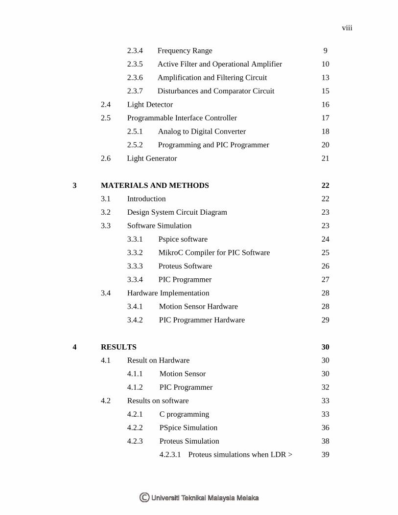
viii
2.3.4 Frequency Range 9
2.3.5 Active Filter and Operational Amplifier 10
2.3.6 Amplification and Filtering Circuit 13
2.3.7 Disturbances and Comparator Circuit 15
2.4 Light Detector 16
2.5 Programmable Interface Controller 17
2.5.1 Analog to Digital Converter 18
2.5.2 Programming and PIC Programmer 20
2.6 Light Generator 21
3 MATERIALS AND METHODS 22
3.1 Introduction 22
3.2 Design System Circuit Diagram 23
3.3 Software Simulation 23
3.3.1 Pspice software 24
3.3.2 MikroC Compiler for PIC Software 25
3.3.3 Proteus Software 26
3.3.4 PIC Programmer 27
3.4 Hardware Implementation 28
3.4.1 Motion Sensor Hardware 28
3.4.2 PIC Programmer Hardware 29
4 RESULTS 30
4.1 Result on Hardware 30
4.1.1 Motion Sensor 30
4.1.2 PIC Programmer 32
4.2 Results on software 33
4.2.1 C programming 33
4.2.2 PSpice Simulation 36
4.2.3 Proteus Simulation 38
4.2.3.1 Proteus simulations when LDR > 39

ix
2.91V
4.2.3.2 Proteus simulations when LDR
2.91V
41
4.3 Results on completed motion sensor design 42
4.3.1 Result on the amplification 42
4.3.2 Result on the output 44
4.3.3 Result on the range of detection 44
5 DISCUSSION ON RESULTS 45
5.1 Output Signal 45
5.2 The Design 46
5.3 Sensing Distance 46
6 SUMMARY AND CONCLUSION 47
6.1 Summary of the entire work 47
6.2 Strength and weaknesses of the design 47
6.2.1 Strength of the design 48
6.2.2 Weakness of the design 48
6.3 Recommendation for future work 48
REFERENCES 50
APPENDICES 51
x
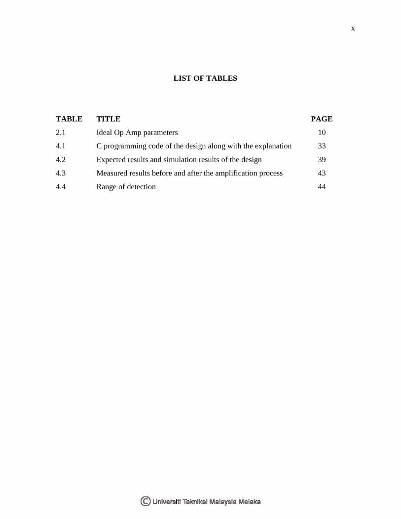
LIST OF TABLES
TABLE TITLE PAGE
2.1 Ideal Op Amp parameters 10
4.1 C programming code of the design along with the explanation 33
4.2 Expected results and simulation results of the design 39
4.3 Measured results before and after the amplification process 43
4.4 Range of detection 44
xi
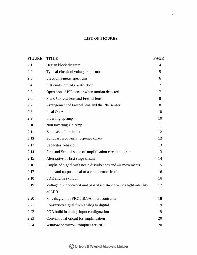
LIST OF FIGURES
FIGURE TITLE PAGE
2.1 Design block diagram 4
2.2 Typical circuit of voltage regulator 5
2.3 Electromagnetic spectrum 6
2.4 PIR dual element construction 7
2.5 Operation of PIR sensor when motion detected 7
2.6 Plano Convex lens and Fresnel lens 8
2.7 Arrangement of Fresnel lens and the PIR sensor 8
2.8 Ideal Op Amp 10
2.9 Inverting op amp 10
2.10 Non inverting Op Amp 11
2.11 Bandpass filter circuit 12
2.12 Bandpass frequency response curve 12
2.13 Capacitor behaviour 13
2.14 First and Second stage of amplification circuit diagram 13
2.15 Alternative of first stage circuit 14
2.16 Amplified signal with noise disturbances and air movements 15
2.17 Input and output signal of a comparator circuit 16
2.18 LDR and its symbol 16
2.19 Voltage divider circuit and plot of resistance verses light intensity
of LDR
17
2.20 Pins diagram of PIC16f876A microcontroller 18
2.21 Conversion signal from analog to digital 19
2.22 PGA build in analog input configuration 19
2.23 Conventional circuit for amplification 20
2.24 Window of microC compiler for PIC 20
xii
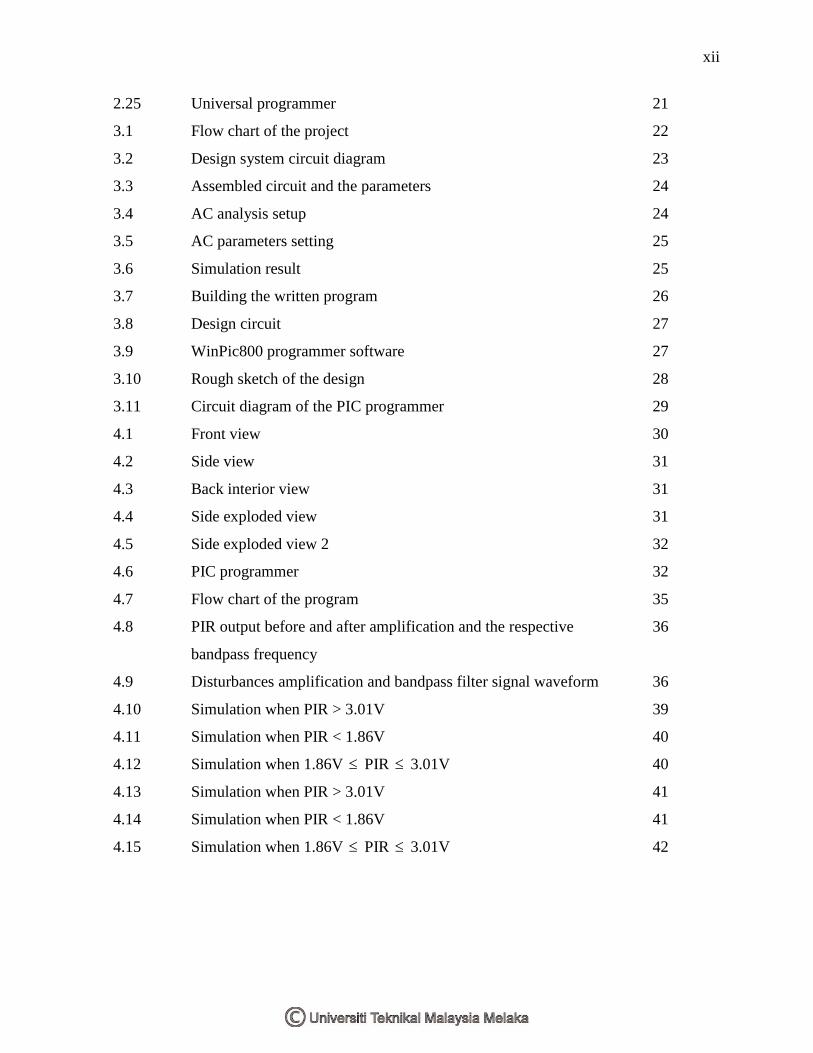
2.25 Universal programmer 21
3.1 Flow chart of the project 22
3.2 Design system circuit diagram 23
3.3 Assembled circuit and the parameters 24
3.4 AC analysis setup 24
3.5 AC parameters setting 25
3.6 Simulation result 25
3.7 Building the written program 26
3.8 Design circuit 27
3.9 WinPic800 programmer software 27
3.10 Rough sketch of the design 28
3.11 Circuit diagram of the PIC programmer 29
4.1 Front view 30
4.2 Side view 31
4.3 Back interior view 31
4.4 Side exploded view 31
4.5 Side exploded view 2 32
4.6 PIC programmer 32
4.7 Flow chart of the program 35
4.8 PIR output before and after amplification and the respective
bandpass frequency
36
4.9 Disturbances amplification and bandpass filter signal waveform 36
4.10 Simulation when PIR > 3.01V 39
4.11 Simulation when PIR < 1.86V 40
4.12 Simulation when 1.86V PIR 3.01V 40
4.13 Simulation when PIR > 3.01V 41
4.14 Simulation when PIR < 1.86V 41
4.15 Simulation when 1.86V PIR 3.01V 42

xiii
LIST OF ABBREVIATIONS AND SYMBOLS
A - Ampere
AC - Alternating Current
ADC - Analog Digital Converter
C - Capacitor
DC - Direct Current
FET - Field Effect Transistor
Hz - Hertz
IR - Infrared
In - Input current
L - Working distance
LDR - Light Dependent Resistor
Op Amp - Operational amplifier
PIC - Programmable Interface Controller
PIR - Passive Infrared or Pyroelectric Infrared
R - Resistor
Rf - Feedback resistor
Rg - Input resistor
V - Volt
Vb - Velocity
Vcc - Power supply voltage
Vin - Input voltage
Vos - Input offset voltage
Vout - Output voltage
Zin - Input impedance
Zout - Output inpedence
a - Gain

xiv
f - Frequency
fb - Focal length
mA - mili Ampere
mm - milimeter
m/s - meter/second
nF - nano Farad
nm - nanometer
uF - micro Farad
um - micrometer

xv
LIST OF APPENDICES
APPENDIX TITLE
A PIR LHi 968 sensor datasheet
B TS2937 voltage regulator datasheet
C Frequency verses velocity with various focal length
D PIC16F876A datasheet
E Operational Amplifier datasheet
CHAPTER 1
INTRODUCTION
1.1 Introduction
Everyday human activities are leads by light inconsiderate whether during daylight or
night time. Without the light as our guidance, human cannot complete their desire tasks such
as finding the route to their destination. Ancient human used firewood as their tool to guide
them and then slowly improve. Nowadays with latest and innovative creation human now
depends alternatively on artificial lighting system whether within a covered building or an
open areas. Few examples such as pilot landing the airplane by following and using guidance
from the lighting system on the route track, human staying within a building can see clearly
the path to their destination and do other activities even though is daylight, and vehicle using
artificial lighting system to see the route at night when traveling. Without the light, many
disaster and unwanted events may be happened such as car crash accident on the route at night,
pedestrian suffer from hurt when they hit or kick or bang into obstacles, and most apparent is
human have to live in the dark.
1.2 Problem Statement
Conventional lighting system normally designed for adults and youngster to reach for the
light. Children especially encounter problems to reach and turn on the light. This is because
the location of the switch normally mounted on a place where it is easy for youngsters and
adults to turn on but not for children. Some parents will taking an alternative way by
modifying the switch such as changing the whole wall switch with a switch where it have a
2
long stick for children to pull or adding another switch parallel with the switch so that
everyone can turn on the light.
Conventional lighting system has to be manually operated to turn on the light. At the night
time, peoples have to search the location of the switch in the dark environment to turn on the
light. Some peoples will get hurts and frustrated when searching the switch in the night time or
in the dark environment.
At outside from a building or open area, light not usually available everywhere. With
invention of dc power supplies such as battery, most peoples able to utilize this technology to
power up their portable device. By using this portable battery, a lighting system can be carry
all over the world without interruption such as have to fix at one position like ac lighting. In
other way, the design is very flexible to be used everywhere and anyone.
1.3 Project Objectives
The objectives of this project are to design a portable lighting system with automatic
lighting capability when it senses a motion from human when passing through the within
sensing areas. The design also capable to saving electricity because it will automatically turn
off after certain of time when human detection are no longer detected within sensing areas. By
using this design, human lifestyle can be improve because it is no longer required to depends
on the conventional manual switch and a new feature is added in that is the portability lighting
system capability which allow to carry and install or place at a desire place and location. This
design is focusing on helping children when no light present especially at night time or in dark
area to leads them to their destination or allow then to do their activities.
1.4 Project Scopes
The scopes of this project are to design a portable device mainly to detect presence of

3
the children, it is running dc power supply, the design detection range is in low range, it is only
used in indoor and the output is only light. Passive Infrared sensor (PIR) will be used as a
motion sensor detector. On and off control of the lighting is depends on the light dependent
sensor (LDR) and battery voltage 9 volt is being used in this project. Also this project used
microcontroller PIC 16f8776a as the embedded controller and the language for the
programming part is C language.
CHAPTER 2
LITERATURE REVIEW AND PROJECT BACKGROUND
2.1 Introduction
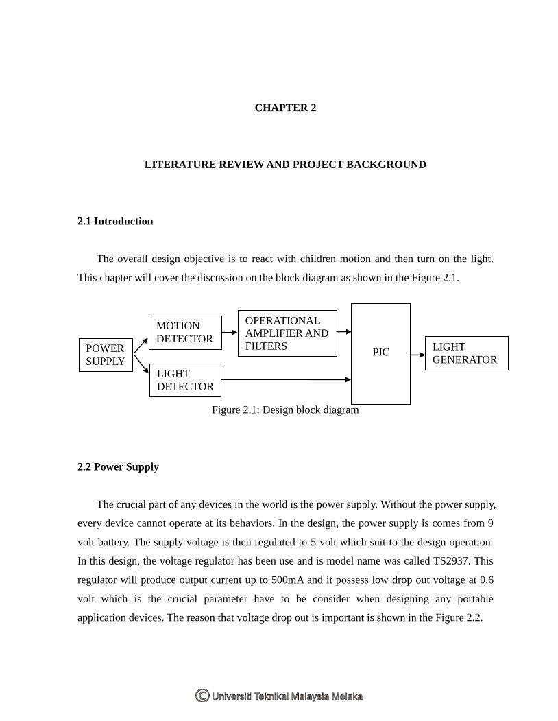
The overall design objective is to react with children motion and then turn on the light.
This chapter will cover the discussion on the block diagram as shown in the Figure 2.1.
Figure 2.1: Design block diagram
2.2 Power Supply
The crucial part of any devices in the world is the power supply. Without the power supply,
every device cannot operate at its behaviors. In the design, the power supply is comes from 9
volt battery. The supply voltage is then regulated to 5 volt which suit to the design operation.
In this design, the voltage regulator has been use and is model name was called TS2937. This
regulator will produce output current up to 500mA and it possess low drop out voltage at 0.6
volt which is the crucial parameter have to be consider when designing any portable
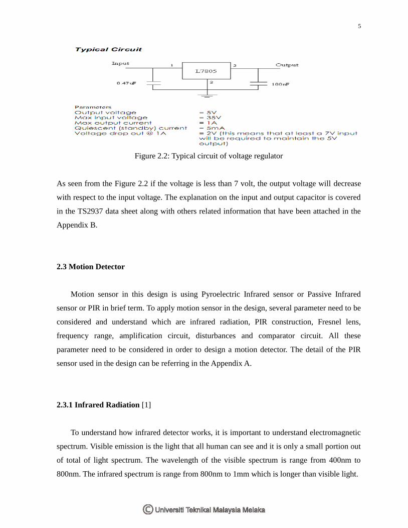
application devices. The reason that voltage drop out is important is shown in the Figure 2.2.
POWER
SUPPLY
MOTION
DETECTOR
LIGHT
DETECTOR
OPERATIONAL
AMPLIFIER AND
FILTERS
PIC LIGHT
GENERATOR
5
Figure 2.2: Typical circuit of voltage regulator
As seen from the Figure 2.2 if the voltage is less than 7 volt, the output voltage will decrease
with respect to the input voltage. The explanation on the input and output capacitor is covered
in the TS2937 data sheet along with others related information that have been attached in the
Appendix B.
2.3 Motion Detector
Motion sensor in this design is using Pyroelectric Infrared sensor or Passive Infrared
sensor or PIR in brief term. To apply motion sensor in the design, several parameter need to be
considered and understand which are infrared radiation, PIR construction, Fresnel lens,
frequency range, amplification circuit, disturbances and comparator circuit. All these
parameter need to be considered in order to design a motion detector. The detail of the PIR
sensor used in the design can be referring in the Appendix A.
2.3.1 Infrared Radiation [1]
To understand how infrared detector works, it is important to understand electromagnetic
spectrum. Visible emission is the light that all human can see and it is only a small portion out
of total of light spectrum. The wavelength of the visible spectrum is range from 400nm to
800nm. The infrared spectrum is range from 800nm to 1mm which is longer than visible light.
6
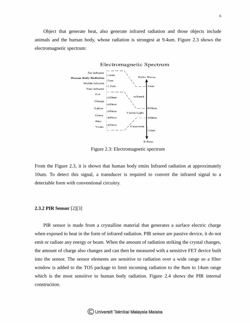
Object that generate heat, also generate infrared radiation and those objects include
animals and the human body, whose radiation is strongest at 9.4um. Figure 2.3 shows the
electromagnetic spectrum:
Figure 2.3: Electromagnetic spectrum
From the Figure 2.3, it is shown that human body emits Infrared radiation at approximately
10um. To detect this signal, a transducer is required to convert the infrared signal to a
detectable form with conventional circuitry.
2.3.2 PIR Sensor [2][3]
PIR sensor is made from a crystalline material that generates a surface electric charge
when exposed to heat in the form of infrared radiation. PIR sensor are passive device, it do not
emit or radiate any energy or beam. When the amount of radiation striking the crystal changes,
the amount of charge also changes and can then be measured with a sensitive FET device built
into the sensor. The sensor elements are sensitive to radiation over a wide range so a filter
window is added to the TO5 package to limit incoming radiation to the 8um to 14um range
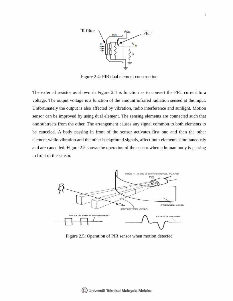
which is the most sensitive to human body radiation. Figure 2.4 shows the PIR internal
construction.
7
Figure 2.4: PIR dual element construction
The external resistor as shown in Figure 2.4 is function as to convert the FET current to a
voltage. The output voltage is a function of the amount infrared radiation sensed at the input.
Unfortunately the output is also affected by vibration, radio interference and sunlight. Motion
sensor can be improved by using dual element. The sensing elements are connected such that
one subtracts from the other. The arrangement causes any signal common to both elements to
be canceled. A body passing in front of the sensor activates first one and then the other
element while vibration and the other background signals, affect both elements simultaneously
and are cancelled. Figure 2.5 shows the operation of the sensor when a human body is passing
in front of the sensor.
Figure 2.5: Operation of PIR sensor when motion detected
FET IR filter
8
2.3.3 Fresnel Lens [3]
To enable detection few feet away, Fresnel lens is required. Beside that the PIR sensor
itself is inefficient if it does not have a lens to focus the radiation. A Fresnel lens is a Plano
Convex lens that has been collapsed on it to form a flat lens that retains its optical
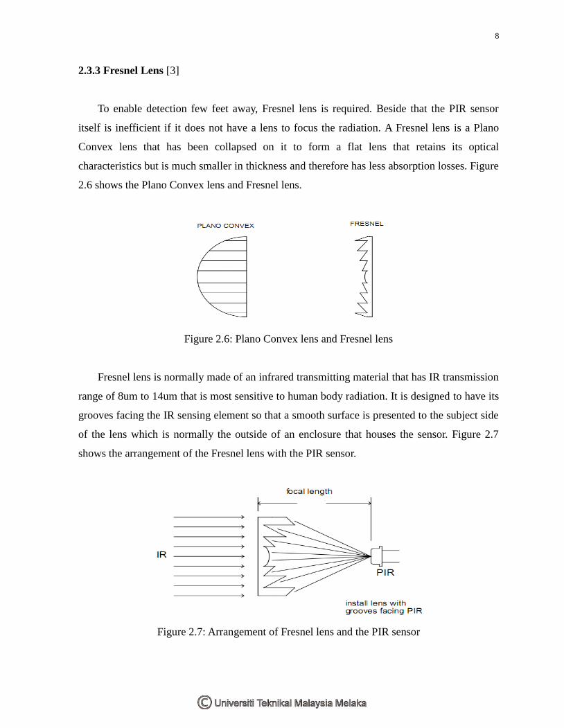
characteristics but is much smaller in thickness and therefore has less absorption losses. Figure
2.6 shows the Plano Convex lens and Fresnel lens.
Figure 2.6: Plano Convex lens and Fresnel lens
Fresnel lens is normally made of an infrared transmitting material that has IR transmission
range of 8um to 14um that is most sensitive to human body radiation. It is designed to have its
grooves facing the IR sensing element so that a smooth surface is presented to the subject side
of the lens which is normally the outside of an enclosure that houses the sensor. Figure 2.7
shows the arrangement of the Fresnel lens with the PIR sensor.
Figure 2.7: Arrangement of Fresnel lens and the PIR sensor
Recommended