Aviation Electricity andElectronics—Radar
NAVEDTRA 14339
NONRESIDENTTRAININGCOURSE
DISTRIBUTION STATEMENT A: Approved for public release; distribution is unlimited.

PREFACE
About this course:
This is a self-study course. By studying this course, you can improve your professional/military
knowledge, as well as prepare for the Navy-wide advancement-in-rate examination. It contains
subject matter about day-to-day occupational knowledge and skill requirements and includes
text, tables, and illustrations to help you understand the information. An additional important
feature of this course is its reference to useful information to be found in other publications. The
well-prepared Sailor will take the time to look up the additional information.
Any errata for this course can be found at https://www.advancement.cnet.navy.mil under
Products.
History of the course:
• Aug 2003: Original edition released.
• Aug 2003: Original edition released.
Published by
NAVAL EDUCATION AND TRAINING
PROFESSIONAL DEVELOPMENT
AND TECHNOLOGY CENTER
https://www.cnet.navy.mil/netpdtc
POINTS OF CONTACT ADDRESS
• E-mail: [email protected]
• Phone:
Toll free: (877) 264-8583
Comm: (850) 452-1511/1181/1859
DSN: 922-1511/1181/1859
FAX: (850) 452-1370
COMMANDING OFFICER
NETPDTC N331
6490 SAUFLEY FIELD ROAD
PENSACOLA FL 32559-5000
Technical content assistance. Contact a Subject Matter Expert at https://www.advancement.cnet.navy.mil/welcome.asp,
under Exam Info, contact your Exam Writer.
NAVSUP Logistics Tracking Number
0504-LP-102-0292

TABLE OF CONTENTS
CHAPTER PAGE
APPENDIX
ASSIGNMENT QUESTIONS follow Index.
1. Radar . . . . . . . . . . . . . . . . . . . . . . . . . . . . . . . . . . . . . . . . . . . . . . . . . . . . . . . . . 1-1
2. Identification Friend or Foe (IFF) Systems . . . . . . . . . . . . . . . . . . . . . . . . . . . . . 2-1
I. Glossary of Common Military Terms. . . . . . . . . . . . . . . . . . . . . . . . . . . . . . . AI-1
II. References Used to Develop This NRTC . . . . . . . . . . . . . . . . . . . . . . . . . . . . AII-1
III. Answers to Review Questions Chapters 1 and 2 . . . . . . . . . . . . . . . . . . . . . . . AIII-1


CHAPTER 1
RADAR
Possibly one of the greatest inventions to come out
of World War II is the radar unit. The term radar is
derived from the words Radio Detection And Ranging.
Radar refers to electronic equipment used to detect the
presence of objects and to determine their direction,
altitude, and range by means of reflected
electromagnetic energy. The development of radar into
highly complex systems, as it is known today, is the
accumulation of many years of developments and
refinements contributed by many people of many
nations. While the development of radar dates back
many years, the general principles used in the past still
apply today.
FUNDAMENTALS OF RADAR
LEARNING OBJECTIVE: Identify the
fundamental characteristics of radar to include
range, velocity, range measurements, azimuth,
and accuracy. In addition, recognize the factors
that affect radar performance to include
pulsewidth, peak power, beamwidth, receiver
sensitivity, and atmospheric conditions.
The word radar applies to electronic equipment
used to detect the presence of objects. Radar determines
an object’s direction, altitude, and range by using
reflected electromagnetic energy. The characteristics of
radar discussed in this section include the range,
azimuth, resolution, and accuracy. Also, some of the
factors that affect radar performance will be discussed.
RANGE
Radar measurement of range, or distance, is
possible because radiated radio frequency (RF) energy
travels through space in a straight line at a constant
speed. However, the straight path and constant speed
are altered slightly by varying atmospheric and weather
conditions.
VELOCITY
RF energy travels at the speed of light, about
186,000 statute miles per second, 162,000 nautical
miles per second, or 300 million meters per second.
Radar timing is expressed in microseconds (µs); the
speed of radar waves is given as 328 yards or 984 feet
per microsecond. One nautical mile is equal to about
6,080 feet. This means that it takes RF energy about
6.18 microseconds to travel 1 nautical mile.
RANGE MEASUREMENT
The pulse radar set determines range by measuring
the elapsed time during which the emitted pulse travels
to the target and returns. Since two-way travel is
involved, a total time of 12.36 microseconds per
nautical mile will elapse between the start of the pulse
from the antenna and its return from the target. The
range in nautical miles can be found by measuring the
elapsed time during a round trip radar pulse (in
microseconds) and dividing this quantity by 12.36 as
shown below:
Range =elapsed time
12.36
Minimum Range
Radar duplexers alternately switch the antenna
between the transmitter and receiver so that one
antenna can be used for both functions. The timing of
this switching is critical to the operation of the radar
and directly affects the minimum range of the radar
system. A reflected pulse will not be received during
the transmit pulse and subsequent receiver recovery
time. Therefore, any reflected pulses from close targets
that return before the receiver is connected to the
antenna will be undetected.
The minimum range of capability of pulse radar is
determined by the time of the transmitter pulse, or
pulsewidth (PW), plus the recovery time of the
duplexer and the receiver. The minimum range (in
yards) at which a target can be detected is equal to the
PW (in microseconds) plus the recovery time, divided
by 2 and multiplied by 328 yards. Stated as a formula:
Minimum range = PW + recovery time/2 x 328 yd
= (PW + recovery time) x 164 yd
Targets closer than these ranges cannot be seen because
the receiver is inoperative for the period of time
necessary for a signal to travel this distance. An
1-1

increase in recovery time caused by a bad TR tube in
the duplexer not only increases minimum range but can
also decrease the receiver sensitivity.
Maximum Range
The higher the frequency of a radar wave, the
greater the attenuation due to the weather effects. Gases
and water vapor that make up the atmosphere absorb
energy from the radiated pulse. Frequencies below
3,000 MHz are not appreciably attenuated under
normal conditions, while frequencies above 10,000
MHz are highly attenuated. Attenuation of the
transmitted pulse results in a decrease in the ability of
the radar to produce useable echoes at long ranges. A
usable echo is defined as the smallest signal that a
receiver-indicator is able to detect, amplify, and present
so that the observer can visually distinguish it from
noise signal on a radar indicator.
At lower frequencies, higher transmitter power can
be developed more easily. Also, there is greater
refraction and diffraction (bending of the waves).
Therefore, lower radar frequencies are better suited for
extremely long-range search radar conditions.
The maximum range of a pulse radar system
depends upon transmitted power, pulse repetition
frequency (PRF), and receiver sensitivity. The peak
power of the transmitted pulse determines what
maximum range that the pulse can travel to a target and
still return as a usable echo. Sufficient time must be
allowed between transmitted pulses for an echo to
return from a target located at the maximum range of
the system.
AZIMUTH (BEARING)
The azimuth or bearing of a target is its clockwise
angular displacement in the horizontal plane with
respect to true north as distinguished from magnetic
north. This angle may be measured with respect to the
heading of an aircraft containing the radar set; in this
case, it is called “relative bearing.” The angle may be
measured from true north, giving true bearing, if the
system contains stabilization equipment. The angle is
measured by using the directional characteristics of the
unidirectional antenna and determining the position of
the antenna when the strongest echo is received from
the target.
Radar antennas are constructed of radiating
elements and reflectors. Some types use a director
element to produce a narrow beam of energy in one
direction. The pattern produced in this manner permits
the beaming of maximum energy in a desired direction.
The transmitting pattern of an antenna is also its
receiving pattern. An antenna can be used to transmit
energy, receive reflected energy, or both.
RESOLUTION
The range resolution of a radar system is the
minimum resolvable separation, in range, of two targets
of the same bearing. Range resolution is a function of
the width of the transmitted pulse, the type and size of
the targets, and the characteristics of the receiver and
indicator. With a well-designed system, sharply defined
targets on the same bearing should be resolved if their
ranges differ by the distance the pulse travels in
one-half of the time of the pulsewidth (164 yards per
microsecond of PW). For example, if a radar set has a
pulsewidth of 5 microseconds, the targets would have
to be separated by more than 820 yards before they
would appear as two blips on the indicator. The
formulas for range resolution and minimum target
separation are listed below.
Range resolution = PW x 328 yd
Minimum target separation = PW x 164 yd
The azimuth resolution is the ability to separate
targets at the same range but on different bearings, and
is a function of the antenna beamwidth and range of the
targets. Antenna beamwidth may be defined as the
angular distance between the half-power points of an
antenna’s radiation pattern. (Half-power points are
those points at which the transmitted power is one-half
the maximum value that is radiated along the lobe
center.) Two targets at the same range, in order to be
resolved as being two targets instead of one, must be
separated by at least one beamwidth. Strong multiple
targets appearing as one target can often be resolved by
azimuth (bearing) by reducing the gain of the receiver
until only the strongest portions of the echoes appear on
the indicator.
ACCURACY
The accuracy of a radar unit is a measure of its
ability to determine the correct range and bearing of a
target. The degree of accuracy in azimuth is determined
by the effective beamwidth and is improved as the
beamwidth is narrowed. On a plan position indicator
(PPI), the echo begins to appear when energy in the
edge of the beam first strikes the target. The echo is
strongest as the axis of the beam crosses the target, but
the echo continues to appear on the scope as long as any
part of the beam strikes the target. The target appears
1-2

wider on the PPI than it actually is, and the relative
accuracy of the presentation depends in a large measure
on the width of the radar beam and the range of the
target.
The true range of a target is the actual distance
between the target and the radar unit, as shown in (fig.
1-1). In airborne radar, the true range is called the slant
range. The term slant range indicates that the range
measurement includes the effect of difference in
altitude.
The horizontal range of a target is a straight-line
distance (fig. 1-1) along an imaginary line parallel to
the earth’s surface. This concept is important to the
radar observer because an airborne target, or the
observer’s aircraft, need only to travel represented by
its horizontal range to reach a position directly over its
target. For example, an aircraft at a slant or true range of
10 miles and at an altitude of 36,000 feet above the
radar observer’s aircraft possesses a horizontal range of
only 8 miles.
FACTORS AFFECTING RADAR
PERFORMANCE
Many factors or elements affect the operating
performance of a radar system. Some of these factors or
elements are pulsewidth, peak power, beamwidth,
receiver sensitivity, antenna rotation, and atmospheric
conditions. Other key factors are the maintenance
upkeep and the operator’s knowledge of the radar
system. The ability to keep the system operating at peak
efficiency will also influence the overall capabilities
and limitations of the unit.
Pulsewidth
Pulsewidth or pulse duration is the time interval
between specific points on the leading edge and trailing
edge of a pulse, shown in figure 1-2. The longer the
pulsewidth, the greater the range capabilities of the
radar. This is due to the greater amount of RF energy
present in each pulse. In addition, consider the fact that
narrow bandpass receivers can be used, thus reducing
the noise level. An increase in pulsewidth, however,
increases the minimum range and reduces the range
resolution capabilities of the system.
Peak Power
The peak power of a radar unit is its useful power,
which is the maximum power of a pulse of RF energy
from the radar unit’s transmitter, shown in figure 1-2.
The range capabilities of the radar will increase with an
increase in peak power. Doubling the peak power (a
3-dB gain) will increase the range capabilities by
roughly 25 percent.
Beamwidth
The beamwidth is specified in degrees between the
half power points in the radiation pattern. The effective
beamwidth of a radar system is not a constant quantity,
because it is affected by the receiver gain (sensitivity)
and the size and range of target.
The narrower the beamwidth, the greater the
concentration of energy. The more concentrated the
beam, the greater the range capabilities for a given
amount of transmitted power.
Receiver Sensitivity
The sensitivity of a receiver is a measure of the
ability of the receiver to amplify and make useable a
very weak signal. Increasing sensitivity of the receiver
increases both the detection ranges of the radar and the
radar’s ability to detect smaller targets. Sensitive
1-3
10MI.
SLANTRANGE
8 MI.
41,000 FT.
5,000 FT.
TARGET
OCEAN SURFACE
AEf01001
Figure 1-1.—Slant range versus horizontal range.
PW
AEf01002
Figure 1-2.—Pulse of RF energy.

receivers are easier to jam; however, the interference
will be more apparent on the indicator.
Antenna Rotation
The more slowly the antenna rotates the greater the
detection range of the radar. Thus, an antenna that is not
rotating would afford the greatest range in the direction
it is pointing, within the limits of the radar. For tactical
reasons, it is best not to stop the antenna from rotating
and point the antenna beam at the target, except
momentarily, and then only to gain information on the
composition of the target.
Atmospheric Conditions
Several conditions within the atmosphere can
adversely affect radar performance. Normally, the path
of radar signals through the atmosphere, whether the
paths are direct or reflected, are slightly curved. These
signals travel through the atmosphere at speeds that
depend upon temperature, atmospheric pressure, and
the amount of water vapor present in the atmosphere.
Generally, the higher the temperature, the lower the
atmospheric pressure; and the smaller the content of
water vapor, the faster the signal will travel.
The bending of radar waves due to a change in
density of the medium through which they are passing
is termed refraction. The bending that occurs is
indicated by the difference in the index of refraction
from one substance to another. The density of the
atmosphere changes at a gradual and continuous rate;
therefore, the index of refraction changes gradually
with increased height.
The temperature and moisture content of the
atmosphere normally decreases with height above the
surface of the earth. Under certain conditions, the
temperature may first increase with height and then
begin to decrease. Such a situation is called
“temperature inversion.” More important, the moisture
content may decrease more rapidly with height just
above the sea. This effect is called “moisture lapse.”
Either temperature inversion or moisture lapse,
alone or in combination, can cause a large change in the
refraction index of the atmosphere. The result is a
greater bending of the radar waves passing through the
abnormal condition. The increased bending in such a
situation is referred to as “ducting,” and may greatly
affect radar performance. The radar horizon may be
extended or reduced, depending on the direction in
which the radar waves are bent. The effect of ducting is
illustrated in figure 1-3.
Water droplets and dust particles diffuse radar
energy through absorption, reflection, and scattering.
This leaves less energy to strike the target so the return
echo is smaller. The overall effect is reduction in the
useable range. Useable range varies widely with
weather conditions. The higher the frequency of the
radar system, the more it is affected by weather
conditions such as rain and or clouds.
Q1-1. What does the acronym radar mean?
Q1-2. What is the speed of electromagnetic energy
when it travels through air?
Q1-3. What is the minimum range for a radar
system with a pulsewidth of 10.5 s, which
has a recovery time of 0.5 s?
Q1-4. What is the range of target when the elapsed
time for the radar pulse to travel to the target
and return is 370.8 microseconds?
Q1-5. What factors determine the minimum range of
a pulse radar system?
Q1-6. The maximum range of a pulse radar system
depends upon what three factors?
Q1-7. Define range resolution of a radar system.
Q1-8. What effect is achieved by increasing the
length of a pulsewidth?
Q1-9. What term is used to describe the situation in
which atmospheric temperature first in-
creases with altitude and then begins to
decrease?
Q1-10. The bending of radar waves due to a change
in density of the medium through which they
are passing is known by what term?
1-4
ACTUAL RANGE
NO DUCT
ACTIONSURFACE
DUCT
WARM
AIR
COLDAIR
NORMAL
RANGE
AEf01003
Figure 1-3.—Ducting effect on a radar wave.

RADAR CONSTANTS AND
TRANSMISSION METHODS
LEARNING OBJECTIVE: Identify basic
constants associated with radar and the three
major transmission methods.
Although all radar systems operate on the same
basic principles, each varies according to its function.
Certain constants are associated with any radar. These
constants are chosen for a particular radar system,
depending on its tactical use, the accuracy required, the
range to be covered, the physical size of the system, and
the energy transmission methods incorporated.
CARRIER FREQUENCY
Carrier frequency is the frequency at which the
electromagnetic energy is transmitted. The principal
factors influencing the selection of a carrier frequency
are the desired directivity of the radiated beam, the
desired physical size of the antenna, and the generation
and reception of RF energy. The antenna should be
highly directive to permit the determination of
direction and to concentrate the transmitted energy so
that a greater amount of it is useful. The higher the
carrier frequency, the shorter the wavelength; hence the
smaller the antenna system. For example, the carrier
frequency for a radar set intended for airborne use has
to be fairly high (usually on the order of 10,000 MHz)
so that a small reflector can be used. Some ground radar
systems use frequencies so low that they must have
antenna reflectors more than 100 feet long to attain the
desired directivity.
The range of frequencies designated for radar are
divided into bands. Table 1-1 lists the frequency ranges
and typical usage for each of the bands.
1-5
Band Designation Frequency Range Typical Usage
A 0 - 250 MHz Very long range surveillance
B 250 MHz - 500 MHz Very long range surveillance
C 500 MHz - 1 GHz Very long to long range surveillance
D 1 GHz - 2 GHz Long range surveillance, enroute
traffic control
E 2 GHz - 3 GHz Moderate range surveillance,
terminal traffic control, long range
weather
F 3 GHz - 4 GHz Long range tracking
G 4 GHz - 6 GHz Long range tracking, airborne
weather
H 6 GHz - 8 GHz Long range tracking, airborne
weather
I 8 GHz - 10 GHz Short range tracking, missile
guidance, marine radar, airborne
intercept
J 10 GHz - 20 GHz High resolution mapping, satellite
altimetry (Note: 18 GHz to 27 GHz
little use due to H²O absorption)
K 20 GHz - 40 GHz Very high resolution mapping,
airport surveillance (Note: 18 GHz
to 27 GHz little use due to H²O
absorption)
L 40 GHz - 60 GHz Experimental
M 60 GHz - 100 + GHz Experimental
Table 1-1.—Radar frequency bands.

PULSE SHAPE AND WIDTH
In typical pulse radar, the shape and width of the RF
pulse influences minimum range, range accuracy, and
maximum range. The ideal pulse shape would resemble
a square wave having very sharp vertical leading and
trailing edges.
The factors that determine the minimum range of a
system will be discussed first. Since the receiver cannot
receive target reflections while the transmitter is
operating, it should be evident that a narrow pulse is
necessary for short ranges. A sloping trailing edge
extends the width of the transmitter pulse, although it
may add very little to the total power generated.
Therefore, along with a narrow pulse, the trailing edges
should be as near vertical as possible.
A sloping leading edge also affects minimum range
as well as range accuracy since it provides no definite
point from which to measure elapsed time. Using a
starting point at the lower edge of the pulse’s leading
edge will increase minimum range. Using a starting
point high up on the slope will reduce the accuracy of
range measurements at short ranges.
Maximum range is influenced by pulsewidth and
pulse repetition frequency (PRF). Since a target reflects
only a very small part of the transmitted power, the
greater the transmitted power, the greater the strength
of the echo that is received by the radar system. Thus, a
transmitted pulse should quickly rise to its maximum
amplitude, remain at this amplitude for the duration of
the desired pulsewidth, and immediately return to zero
to begin the process once again. Figure 1-4 shows the
effects of different pulse shapes.
PULSE REPETITION FREQUENCY
Sufficient time must be allowed between the
transmitted pulse for an echo to return from any target
located within the maximum workable range of the
system. Otherwise, succeeding transmitted pulses may
obscure the reception of the echoes from the more
distant target. This necessary time interval fixes the
highest frequency that can be used for the pulse
repetition. Both maximum and minimum pulse
repetition frequencies for any radar set depends on the
tactical application required of the system. To reach
great distances, the radar must be capable of radiating
plenty of power during the transmission of the pulse,
and the rest cycle or waiting time must be long enough
to allow the radiated pulse to travel well beyond the
maximum range of the radar and then return. The time
from the beginning of one pulse to the start of the next
pulse (this includes the pulse and the waiting time for
the return of the same pulse) is the pulse repetition time
(PRT), which is the reciprocal of the pulse repetition
frequency; that is,
PRT = 1/PRF.
From this relationship it can be seen that a radar set
having a pulse repetition frequency of 400 pulses per
second has a pulse repetition frequency of 1/400
second, or 2,5000 µs. This indicates that as far as PRF is
concerned, the maximum range of a radar is the
distance a pulse can travel to a target and back in 2,500
µs. To be useful, radar range expressed in time must be
converted to radar range expressed in miles. Since RF
energy travels at a constant velocity of 162,000 nautical
miles per second (186,000 statute miles), a transmitted
pulse will travel 1 nautical mile in 6.18 µs. Remember
that the pulse, to indicate a target 1-mile away, must
travel a mile to the target and a mile back to the
receiver. The pulse travels a radar mile, which is out to
the target and back, and requires 12.36 µs.
As a general rule, the PRF determines the
maximum range of the radar unit. As previously
mentioned, the time interval between the transmitted
pulse and the return echo from the maximum workable
range of a radar determines the highest PRF that can be
used by the radar. If the maximum workable range of a
radar unit is 200 miles, then the pulse repetition time
(PRT) is 2,472 µs (200 x 12.36 µs). See figure 1-5. To
1-6
RANGE ACCURACY REQUIRESA SHARP LEADING EDGE.
SHORT MINIMUM RANGEREQUIRES A SHARP TRAILINGEDGE.
MAXIMUM RANGE REQUIRES AFLAT TOPPED PULSE OF SOMEDURATION.
RANGE RESOLUTION REQUIRESA NARROW PULSE.
AEf01004
GOOD BAD
Figure 1-4.—Pulse shapes and effects.
2 SEC(984 FT.)
2,472 SEC(200 MILES)
AEf01005
Figure 1-5.—Pulsewidth, pulse repetition time, and range.

obtain this, a PRF of 1 / 2,472 µs, or approximately 405
pulses per second (PPS) is necessary.
If, for some reason, the pulse of energy should
travel farther than 200 miles and be reflected, it would
return to the radar after the next pulse is transmitted. An
echo from a target 250 miles out would appear at the
50-mile point on an indicator. How can the operator
determine if the indication is from a target 50-miles
away or from a target 250-miles away that was
reflected by the prior pulse? To eliminate ambiguous
targets, the operator can use a lower PRF. A PRF of 200
PPS will give a PRT of 5,000 µs and a range of about
400 miles; that is, a pulse can travel out approximately
400 miles and return before the next pulse is
transmitted. However, a sweep of only 200 miles is
used on the indicator since that is the normal workable
range. During the additional time, the sweep is blanked
out. Any echo returning after 2,472 µs and up to 5,000
µs is not displayed. The PRF must not be made too low.
The speed of the antenna rotation also has an effect on
the minimum PRF. The radar beam strikes a target for a
relatively short time during a revolution of an antenna.
If the antenna rotates at 20 revolutions per minute, it
completes a revolution every 3 seconds. During this
time the transmitter has fired 600 times if the PRF is
200 PPS. If the beamwidth is 1 degree during its 1
degree of rotation, there will be less than two pulses
sent out and echoes returned from a target.
600 pulses per revolution= 1 2/3 pulse per degree
360 degrees per revolution
A sufficient number of pulses of energy must strike
the target to return an echo that will be useful at the
receiver. If the target is very narrow, the pulse may miss
it entirely; and if it is very large, much of it will not
show up on the scan.
POWER OUTPUT
Although PRF determines the maximum range of
radar, it should be understood that it is also dependent
on the power output of the radar system. The radar must
radiate enough power so that the received echo signal at
the maximum range will have a power level at least
equal to the electronic noise in the receiver.
The generating and amplifying of RF energy at
extremely high frequencies and very high power levels
is primarily determined by the physical construction of
the generating device. Some of high power RF
generating devices used are the magnetron and
klystron. In general these have low interelectrode
capacitance, low transit time, and the ability to handle
very high levels of RF power.
In considering power requirements, distinction
must be made between the two kinds of output powers.
These powers are peak power, which is the power
during the transmission of the pulse, and average
power, which is the average power over the pulse
repetition, illustrated in figure 1-6. While the peak
power can be very high, the average power may be very
low because of the great differences between
pulsewidth and pulse repetition time.
Pulse repetition time is used to figure average
power because it defines the total time from the
beginning of one pulse to the beginning of the next
pulse. Average power (Pavg ) can be figured as follows:
Where: Pavg = average power
Ppk = peak power
PW = pulsewidth
PRT = pulse repetition time
Pavg = Ppk x PW/PRT
Because 1/PRT is equal to PRF, the formula may be
written as follows:
Pavg = Ppk x PW x PRF.
The product of pulsewidth (PW) and pulse
repetition frequency (PRF) in the above formula is
known as the duty cycle of a radar system. The duty
cycle is the ratio of the time on PW to the Pulse
1-7
����������������������������������������������������������������������������������������������������������������������������������������������������������������������������������������������������������������������������������������������������������������������������������������������������������������������������� � � � � � � � � � � � � � � � � � � � � � � � � � � � � � � � � � � � � � �
AEf01006
AVERAGE POWER
PULSEWIDTH
PEAKPOWER
TIME(PRT)
NEXTPULSE
Figure 1-6.—Pulse energy content.

Repetition Time (PRT), as shown in figure 1-7. The
duty cycle is used to calculate both the peak power and
average power of a radar system. The formula for duty
cycle is shown below:
Duty cycle = PW x PRF
Since the duty cycle of a radar is usually known, the
most common formula for average power is expressed
below:
Pavg = Ppk x duty cycle
Transposing the above formula gives us a common
formula for peak power:
Ppk = Pavg/duty cycle
Peak power is usually calculated more often than
average power because most measuring devices
measure average power directly. An example is shown
below:
Pavg = 10 kW
PW = 10 µs
PRF = 1000 PPS
Before figuring Ppk, you must calculate duty cycle
as follows:
duty cycle = PW x PRF
duty cycle = 10 µs x 1000 PPS
duty cycle = 0.01
Now that you have calculated duty cycle, Ppk can be
calculated as follows:
Ppk = Pavg/duty cycle
Ppk = 10 kW/0.01
Ppk = 1,000,000 watts or 1 MW
RADAR DETECTING METHODS
Radar systems are divided into categories based on
their energy transmission method. Although the pulse
method is the most common method of transmitting RF
energy, two other methods are occasionally used in
special applications. These are the continuous wave
(CW) method and the frequency modulation (FM)
method.
Continuous Wave
The continuous wave (CW) method uses the
Doppler effect to detect the presence and speed of an
object moving towards or away from the radar. The
system is unable to determine the range of the object or
to differentiate between objects that lie in the same
direction and are traveling at the same speed. It is
usually used by fire control systems to track
fast-moving targets at close range.
Frequency Modulation
With the frequency modulation (FM) method,
energy is transmitted as radio frequency waves that
continuously vary, increasing and decreasing from a
fixed reference frequency. Measuring the difference
between the frequency of the returned signal and the
frequency of the radiated signal will give an indication
of range. The system works well with stationary or
slow-moving targets, but is not suited for locating
moving objects. It is used in aircraft altimeters that give
a continuous reading of how high the aircraft is above
the earth.
Pulse Modulation
With the pulse modulation method, depending on
the type of radar, energy is transmitted in pulses. The
time interval between transmission and reception is
computed and converted into a visual indication of
range in miles or yards. Pulse radar systems can also be
modified to use the Doppler effect to detect a moving
object. Since this method does not depend on the
relative frequency of the returned signal or on the
motion of the target, it has major advantages over
continuous wave or frequency modulation.
Q1-11. A very high radar antenna indicates what
type of frequency?
Q1-12. Radar frequency ranges are divided into
sections referred to by what term?
Q1-13. The ideal radar pulse shape should have what
characteristics?
Q1-14. What part of a radar pulse affects its range
accuracy?
Q1-15. What is the reciprocal of PRF?
1-8
AEf01007
TIME ON(PULSE WIDTH)
TIME OFF
PULSE REPETITION TIME
Figure 1-7.—Duty cycle.

Q1-16. What two RF generating devices have low
interelectrode capacitance, low transit time,
and the ability to handle very high levels of
RF power?
Q1-17. What is the duty cycle of a radar system that
has an average power of 2 Megawatts and a
peak power of 200 Megawatts?
Q1-18. What radar transmission method does not
depend on target motion or relative frequency
of the returned signal?
BASIC PULSE RADAR SYSTEM
LEARNING OBJECTIVE: Identify the
general components and functions of a basic
airborne pulse radar unit.
Aircraft radar systems, like other complex avionics
systems, are composed of several major subsystems
and many individual circuits. Basically, all radar
systems operate in a similar manner. Since the majority
of radars used today are some variation of a pulse radar
system, the units that will be discussed in this section
will be those used in pulse radar.
BLOCK DIAGRAM OF A PULSE RADAR
SYSTEM
Although modern radar systems are highly
complicated, you can understand their operation by
using a simplified block diagram of a pulse radar
system, shown in figure 1-8A. Figure 1-8B shows the
timing relationship of waveforms in a typical radar set.
The timing trigger pulses are applied to both the
transmitter and the indicator. When a trigger pulse is
applied to the transmitter, a short burst, or pulse, of RF
energy is generated. This energy is conducted along a
transmission line to the radar antenna, from which it is
radiated into space. If the transmitter energy strikes one
or more reflecting targets in its path, some of the
transmitted energy is reflected back to the antenna.
Echo pulses from three reflecting targets at different
ranges are illustrated in the part of the figure 1-8B
labeled “Echo pulses.” The corresponding receiver
output signal is also shown.
The initial and final pulses in the receiver output
signal are caused by the energy that leaks through the
transmit-receive (TR) device when a pulse is being
transmitted.
1-9
NAVEDTRA 1-8A
ANTENNA SERVOSYSTEM
DUPLEXER ASSEMBLY
TRANSMITTERMODULATOR
SYNCHRONIZER/TIMER
DELAYED TRIGGER
POWER SUPPLIES
RANGE MARKS and
VARIABLE DOPPLER GATEMARKER
MASTERTRIGGER REMOTE
TRIGGER
DOPPLERGATE
RECEIVER
ANTENNA
TARGET
TARGET
TARGET
BEARING
ANTENNAPOSITION
RANGEMARKS
TARGET VIDEO
TX and RXRF PULSUES
INDICATORDISPLAY/
VIDEO UNIT
60O
270O
180PI - SCAN PRESENTATION
(MAP-LINE PICTURE)P
O
O0
O45
O45
RAN
GE
MAR
K
Figure 1-8A.—Block diagram of a pulse radar system with signal flow.

The indicator sweep voltage (fig. 1-8B) is initiated
at the same time that the transmitter is triggered. By
delaying the timing trigger pulse fed to the indicator
sweep circuit, it is possible to initiate the indicator
sweep after a pulse is transmitted. (It is also possible to
initiate the indicator sweep before a pulse is
transmitted.)
Note in figure 1-8B that the positive indicator
intensity gate pulse (applied to the cathode-ray tube
control grid) occurs during the indicator sweep time. As
a result, the cathode-ray tube trace occurs only during
the sweep time and is eliminated during the flyback
(retrace) time. The negative range marker gate pulse
also occurs during the indicator sweep time. This
negative gate pulse is applied to a range mark
generator, which produces a series of range marks.
The range marks are equally spaced and last only
for the duration of the range marker gate pulse. When
the range marks are combined (mixed) with the
receiver output signal, the resulting video signal
applied to the indicator may appear as shown in figure
1-8B, and graphically depicted in figure 1-8A.
Synchronizer
The synchronizer or timer circuitry supplies the
pulses of the proper timing to other component parts of
the radar. It insures that all circuits operate in a definite
time relationship with each other and that the interval
between the transmitted pulses is of the proper length.
Radar systems may be classified as either
self-synchronized or externally synchronized systems.
In a self-synchronized system, the timing trigger pulses
are obtained from the transmitter. Also, the repetition
rate of the timing trigger pulses is determined by the
repetition rate of the modulator (or transmitter) pulses.
In an externally synchronized system, the timing
trigger pulses are obtained from a master oscillator. The
master oscillator may be a sine-wave oscillator, a stable
(free-running) multivibrator, or a blocking oscillator. In
an externally synchronized radar system, the repetition
rate of the timing trigger pulses from the master
oscillator determines the pulse repetition rate of the
transmitter.
Trigger pulses for the timer (synchronizer) are also
frequently used to produce gate pulses. When applied
to the indicator, these gate pulses perform the following
functions:
1. Initiate and time the duration of the indicator
sweep voltage.
2. Intensify the CRT electron beam d uring
the sweep period so that the echo pulses may be
displayed.
3. Gate a range mark or range marker generator
so that range marker signals may be superimposed on
the indicator presentation. (The terms marks and
markers are normally interchangeable.) The range
marker generator is discussed in the following
paragraphs.
In a weapons systems radar that requires extremely
accurate target-range data, a movable range marker
maybe used. The range marker is obtained from a range
marker generator and may be a movable range gate or
range step. When a PPI-scope is used, a range circle of
adjustable diameter is used to measure range
accurately. In some cases, you obtain range readings
1-10
TIMING - TRIGGERPULSES
TRANSMITTERPULSES
RECEIVER OUTSIGNAL
INDICATOR SWEEPVOLTAGE
INDICATOR INTENSITYGATE PULSE
RANGE MARKERGATE PULSE
RANGE MARKERS
VIDEO SIGNALTO INDICATOR
ECHO PULSES
0 1 2
0 1 2
TIME
+
0
+
0
-
+
+
0
+
0
-
-
0
+
-
0
-
+
0
-
+
0
+
0
-
-
VO
LTA
GE
SWEEPTIME
FLY-BACK
TIME
NAVEDTRA 1-8B
t
t tt
t t
Figure 1-8B.—Typical time relationship of waveforms.

from the movement of the range marker by turning a
calibrated control dial. In other cases, the range marker
may be used as a range gate for automatic range
tracking. In this case there may be no direct range
readout, or the readout may be a voltmeter calibrated in
range and to which range voltage, equivalent to range
marker position, is applied. This discussion describes
the operation of three types of range markers
(generators): the range gate generator; the range marker
generator; and the range step generator.
The range gate generator, used in conjunction
with a blocking oscillator, generates a movable range
gate. Figure 1-9 shows a simplified block diagram of a
typical radar synchronizer that includes a range gate
generator. The indicator is a B-scope with the range
deflection voltages applied to the vertical plates. The
PRF is controlled by a master oscillator, or
multivibrator, whose output is coupled to a thyratron
trigger.
The range gate circuit receives its input pulse from
the trigger thyratron and generates a delayed range gate
pulse. The delay of this pulse from t0 is dependent on
the position of the target in range when tracking, or on
the manual positioning of the range volts potentiometer
by the operator when in the search mode. The range
gate triggers the range strobe multivibrator, whose
output is amplified and sent to the blocking oscillator.
This oscillator sharpens the pulses, as shown in figure
1-9. The range gate selects the target to be tracked and,
when in track mode, brightens the trace or brackets the
target (depending on the system) to indicate which
target is being tracked.
The range marker generator is used in
conjunction with an astable multivibrator to generate
1-11
BOOTSTRAPRANGESWEEP
MULTI-VIBRATOR
RANGETRACKINGCIRCUITS
RANGE GATEBLOCKING
OSCILLATOR
MANUAL RANGEVOLTS
POTENTIOMETER
TO GATE CIRCUITS DEFLECTION VOLTAGE
TRANSMITTEDPULSE
ECHO PULSE
RANGEGATE
BLOCKINGOSCILLATOR
STROBETRIGGER
AMPLIFIER
PHASESPLITTER
RANGESTROBE
MULTIVIBRATOR
PHANTASTRONMASTER
OSCILLATOR
TRIGGERTHYRATRON
TRIGGERINVERTER
INJECTCIRCUIT
EMITTERFOLLOWER
SWEEPAMPLIFIER
MODULATOR
NAVEDTRA 1-9
t0
Figure 1-9.—Synchronizer with range gate generator.
fixed range marks. Figure 1-10 is a block diagram of a
typical range marker generator. This generator consists
of a ringing oscillator Q1611-Q1612, an emitter
follower Q1613, a countdown multivibrator
Q1616-Q1617, and a pulse-forming amplifier Q1614.
Generation of the marks starts at the ringing oscillator,
which is excited into operation by incoming trigger
pulses. Once in operation, it produces a sinusoidal
output, which is synchronized to the trigger pulses.
This sinusoidal output is then applied to the emitter
follower. This provides interstage buffering by
isolating the ringing oscillator from the countdown
multivibrator. The output coupling circuit of the emitter
follower shifts the average output level to zero (ground)
and clips the negative going portions of the signal. This
allows only the positive half of each sine wave to reach
the countdown multivibrator. The countdown
multivibrator receives a high-frequency positive trigger
corresponding to a fixed interval. This input drives the
countdown multivibrator to develop a negative pulse
train. The period of the pulse train is controlled by the
range marks select switch. This negative output is
applied to the pulse-forming amplifier, where it is
reshaped and passed on to a marker mixer. The output
of a range marker generator can be applied directly to
one of the deflection plates on an A-scope. In this case,
range marker pulses appear simultaneously with the
radar echo signals, and permit estimation of target
range. In B-scope and PPI-scope applications, the
output of the range marker generator is applied to a
video mixer. In this case, radar echo signals are
combined with marker signals before being applied to
the grid of the CRT.
The range step generators, used in conjunction
with an astable multivibrator, generate a movable range
step. Figure 1-11, view A, shows the schematic
diagram and waveforms of a typical range step
generator. The range step generator consists of a
sawtooth voltage generator Q1, a negative clipper CR1,
and a limiting amplifier. Diode CR1 is frequently
referred to as a pickoff diode. The position of the range
step along the indicator time base is controlled by
potentiometer R3. When the range step coincides with
the leading edge of a target echo pulse, the target range
can be read directly from a calibrated range dial
associated with R3. Between times t0 and t1 (fig. 1-11,
view B), the base of transistor Q1 is at ground potential
(zero volts). As a result, Q1 conducts and the Q1
collection voltage (E1) equals Q1 collector-supply
voltage (Vcc) minus the voltage drop across the load
resistor R1. The horizontal dashed line across the E1
waveform indicates the ER3 voltage (fig. 1-11, view A)
at the adjustable tap of potentiometer R3. Since El is
less than ER3 between times t0 and t1, the anode of the
negative clipper CR1 is less positive than the CR1
cathode, and CR1 does not conduct. Hence the CR1
cathode voltage (E2) equals ER3, the voltage at the R3
tap. Between times and the base of transistor Q1 is
driven below cutoff. As a result, Q1 ceases to draw
collector current. When no collector current flows in
Q1, the capacitor C1 changes through the Q1 load
resistor R1, and the collector voltage of Q1 rises
exponentially toward the Q1 collector-supply voltage
(Vcc).
1-12
RINGINGOSC
Q 1611Q 1612
EMITTERFOLLOWER
Q 1613
COUNT DOWNMV
Q 1616Q 1617
PULSE-FORMING
AMP1614
NAVEDTRA 1-10
Figure 1-10.—Range Marker Generator.
NEGATIVECLIPPER
SAW TOOTHVOLTAGE
GENERATOR
ein
ein
R1 CR1
Vcc
E1C1 e out
R4
Q1
R2
R3E2
LIMITINGAMPLIFIER
E
E
E
R3
R3
R3
(A)
0
0
0
0
0 1 2 3
TIME
0 1 2 3
SWEEP TIME
etSTEP
CUTOFF
(B)
INPUT GATE, ein
COLLECTOR VOLTAGE, E1
2CR1 VOLTAGE, E
OUTPUT VOLTAGE OFLIMITING AMPLIFIER eout
_
_
_
_
_
_
_
_
E1
eout
E2
NAVEDTRA 1-11
t t t
t t t t
Figure 1-11.—Range step generator with pickoff diode. (A)
Schematic diagram; (B) waveforms.

At time tz, El exceeds ER3, and diode CR1 conducts.
If the CR1 anode resistance is small, the CR1 cathode
voltage (E2) practically equals El between times t2 and
t3. Following time t3 the base of Q1 returns to ground
potential, and Q1 again conducts. As a result, capacitor
C1 discharges through Q1, and the Q1 collector voltage
decays exponentially toward its initial value. As soon
as E1 becomes less than ER3, CR1 no longer conducts,
and the CR1 cathode voltage again equals ER3. When
the Ez waveform is amplified and limited by the
limiting amplifier, the amplifier output-voltage (eout)
waveform appears, as shown in figure 1-11, view B.
Note that a nearly vertical edge (step) appears in the eout
waveform the instant CR1 begins to conduct (time tz).
By varying the setting of the R3 tap, you can vary the
instant at which CR1 conducts. You can therefore
control the position of the range step by adjusting the
setting of R3. If a linear relationship is to be established
between the delay of the step (t) and the voltage at the
R3 tap (ER3), the Q1 sawtooth collector voltage must be
linear. The eout waveform is applied to the vertical
deflection plates of a cathode-ray tube. Only the portion
of the eout waveform that occurs between times t1 and t3
is displayed on the CRT screen. Remember, the
indicator trace is blanked out during the flyback
(retrace) time.
Modulator
The modulator receives the trigger from the
synchronizer and generates a very high dc pulse to
drive the transmitter. The Pulse Forming Network
(PFN) contained within the modulator, as depicted in
figure 1-12, determines the voltage level and width of
the pulse. The PFN is a series of inductors and
capacitors that produces the nearly rectangular pulse.
The peak power of the transmitted (RF) pulse depends
on the amplitude of the modulator pulse. A basic radar
modulator consists of four parts:
1. A power supply.
2. A storage element (a circuit element or
network for storing energy).
3. A charging impedance (to control the charge
time of the storage element and to prevent short
circuiting of the power supply during the
modulator pulse).
4. A modulator switch (to discharge the energy
stored by the storage element through the
transmitter oscillator during the modulator
pulse).
Transmitter
The transmitter is turned on for the duration of time
of the voltage pulse from the modulator. Its output is a
pulse of high power RF energy, which occurs at the
rate, and the width of the pulse from the modulator. One
type of high power RF generator is the magnetron. A
cutaway view of a magnetron is shown in figure 1-13.
A magnetron is a diode whose anode is made of a
series of resonant cavities. An external magnetic field
between the cathode and plate is perpendicular to the
electric field. As the electrons are emitted from the
cathode, the magnetic field causes them to spiral past
the cavities of the plate before they are collected. As the
electrons pass the cavities, they cause them to oscillate
at resonant frequency determined by the size of the
magnetrons cavities.
A major disadvantage of the magnetron is the
pulse-to-pulse frequency variation because its
frequency stability is dependent on the combination of
the magnetic and electrical fields, either of which is
subject to variations over short periods of time. Another
disadvantage is the physical consideration. The cathode
and anode are included in the frequency determining
system, and are a compromise between desired power
output and required size.
1-13
AEf01012
C1
C2 C3 C4 C5 C6
L1
L2 L3 L4 L5 L6
Figure 1-12.—Pulse forming network.
CATHODE
CAVITIES
ANODE BLOCK
COOLING FINS
PERMANENTMAGNET
WAVEGUIDEATTACHING FLANGE
APERTURE
AEf01013
Figure 1-13.—Cutaway view of a typical radar magnetron.

These disadvantages can be overcome by the use of
a klystron, shown in figure 1-14. In the klystron the
cathode and collector are separated from the frequency
determining fields and can be designed independently
of the RF section to handle the desired power. The
klystron is simply a power amplifier and has no
influence on the frequency determining system.
The klystron shown has three cavities, which must
be tuned to the desired transmit frequency. Notice that
an external RF generator is coupled to the input cavity.
A large negative pulse placed on the cathode turns on
the klystron. The negative pulse comes from the
modulator and causes a cloud of electrons to be
emitted. The cloud of electrons is formed into a beam
by placing a magnetic focusing coil around the klystron
(not shown), which keeps the electrons in a tight group
and away from the sidewalls of the tube. The RF pulse
applied to the input cavity causes the cavity to oscillate
at the RF frequency. RF fields act upon the electrons
that are accelerated by the cathode pulse across the
input and middle cavities. Some electrons are
accelerated, some are decelerated, and others are
unaffected in the movement of the electron beam
towards the collector, causing what is referred to as
“bunching.” The bunching is at the RF frequency that
causes succeeding cavities to oscillate at the same
frequency, accelerating the bunching process. The
design of klystron is such that maximum bunching at
the RF frequency occurs at the last cavity giving up
maximum power to the cavity, which is coupled into a
waveguide as output power to an antenna.
Klystron amplification, power output, and
efficiency can be greatly improved by the addition of
intermediate cavities between the input and output
cavities of a klystron. Additional cavities serve to
velocity-modulate the electron beam and produce an
increase in the energy available at the output for
transmission.
Duplexer
Whenever a single antenna is used for both
transmitting and receiving, as in a typical radar sys-
tem, problems arise. A means of keeping the
high-transmitted power from damaging the receiver,
and a means of keeping the low power received energy
from being dissipated in the transmitter is another. Both
of these problems are solved by the use of a duplexer. A
duplexer is essentially an electronic switch that permits
a radar system to use a single antenna, for both transmit
and receive. The duplexer must transfer the antenna
connection from the receiver to the transmitter during
the transmitted pulse, and back to the receiver during
the return (echo) pulse.
An effective radar duplexer must meet the
following four requirements:
1. During the period of transmission, the switch
must connect the antenna to the transmitter and
disconnect it from the receiver.
2. The receiver must be completely isolated from
the transmitter during the transmission of the
high-power pulse to avoid damage to sensitive receiver
components.
3. After transmission, the switch must rapidly
disconnect the transmitter and connect the receiver to
the antenna. For targets close to the radar to be seen, the
switch must be extremely rapid.
4. The switch should absorb an absolute
minimum of power both during transmission and
reception.
Receiver
Looking again at the radar block diagram (fig.
1-8A), you can see that the received signal is routed
through the duplexer to the receiver. The function of a
receiver in a radar system is to receive and detect radar
1-14
AMPLIFIEDOUTPUTPULSE
OUTPUTCAVITY
INPUTCAVITY
CATHODE
INPUTPULSE
COLLECTOR
1 5
1 5
AEf01014
Figure 1-14.—Basic three-cavity klystron.

returns. The transmitter and antenna generates and
radiates bursts of RF energy, which travels out into
space and hits distant targets. A portion of the RF
energy is reflected back to the antenna. The receiver
mixes this reflected RF energy with RF energy from a
local oscillator to produce a lower frequency called the
intermediate frequency (IF). This type of receiver is
referred to as a superheterodyne receiver, shown in
figure 1-15.
The IF frequency is more desirable when working
with high frequency RF because it is much easier to
build circuitry to handle the lower frequency. The IF
amplifier amplifies the intermediate frequency, and the
target information is removed by the detector and
displayed on the various radar indicators.
The following discussion examines the
components that make up a radar receiver. The local
oscillator generates a RF frequency that is 30 MHz
above the transmit signal. This signal is then applied to
a signal mixer along with the received frequency, which
also produces a 30 MHz difference signal.
The AFC mixer controls the frequency through the
use of a discriminator. The AFC circuitry controls the
frequency by mixing portions of the transmitter
frequency with the local oscillator frequency. The
output of the AFC mixer is directed into a
discriminator, which maintains the frequency of the
local oscillator at a frequency of 30 MHz above the
transmitter frequency. The purpose of the AFC
circuitry is to maintain a constant 30 MHz IF frequency
out of the signal mixer. For example, if the transmitter
frequency changes from 3000 MHz to 3010 MHz, the
AFC circuit would detect the change and shift the
frequency of the local oscillator from 3030 MHz to
3040 MHz. The difference would remain at 30 MHz.
The 30 MHz IF frequency is important because it
affects the overall receiver sensitivity.
The IF amplifier/detector section of a radar
determines the gain, signal-to-noise ratio, bandwidth,
and converts the IF pulses to video pulses to be applied
to the indicators. Typical IF amplifier usually contains
from three to ten amplifier stages. The IF amplifier has
the capability to vary both the bandpass and the gain of
the receiver. Normally, the bandpass is as narrow as
possible without affecting the actual signal energy. The
most critical stage of the IF amplifier section is the
input or first stage. The quality of this stage determines
the noise figure of the receiver and the performance of
the entire receiving system with respect to detection of
small objects at long ranges. Gain and bandwidth are
not the only considerations in the design of the first IF
stage. Another consideration is noise generation. Noise
generation in this stage must be low. Noise generated in
the input IF stage will be amplified by succeeding
stages and may exceed the echo signal in strength.
The function of the detector within the receiver is
to convert the IF pulses into video pulses, from there
video pulses are applied to various indicators. A more
in-depth discussion of radar receiver circuitry can be
found in NEETS, Module 18, Radar Principles.
Indicators
Target information must be made available for
quick analysis by the radar operator for radar to be
useful. After echoes have been received and detected in
the receiver section of the radar, they are ready for
display. Indicators are triggered to initiate a sweep at
the time the transmitter produces its output. As the
indicator sweep passes over the viewing screen, the
received targets or echoes are shown by a bright spot or
blip on the screen. The distance from the start of the
sweep to the blip is the actual range to the object or
target. At this point the signal is amplified to a level
where it can be properly displayed. The exact time
required for the transmitted RF burst to travel to the
target and for its echo to return is measured. One half of
this total elapsed time measurement represents target
range. A few examples of radar display indicators are
the Plan Position Indicator (PPI), Range Height
Indicator (RHI), and Amplitude Indicator (A-scope).
The PPI is the most common indicator used for
radar displays. These types display the direction and
range of the target. The PPI presentation is practically
1-15
MIXER
LOCALOSCILLATOR
VIDEO
I.F.AMPLIFIER
ANDDETECTOR
SIGNALMIXER
AFC
I.F.
R.F.
AFCDISCRIMINATOR
INDICATORS
TRANSMITTER WAVE GUIDE
DUPLEXER
ANTENNA
AEf01015
Figure 1-15.—Radar receiver block diagram.

an exact replica of the region scanned by the radar
antenna. Distance along the radial sweep line
represents target range. Rotation of the radial sweep
line, synchronized with the antenna’s rotation,
produces a circular display.
When echo signals are applied to the control grid
(or cathode) of the PPI CRT during the sweep period,
the brightness of portions of the radial sweep line is
increased. An increase in the brightness of portions of
the PPI radial sweep line results in a map-like
presentation, as shown in figure 1-16.
Another indicator used in radar is the RHI,
sometimes called an E-scope. It is used with height
finding search radars to obtain altitude information.
The E-scope displays targets in elevation above the
earth in kilometers or feet versus range in kilometers or
nautical miles. The sweep is displayed as an angle that
represents the elevation angle of the antenna. The start
of the sweep is synchronized with the transmitted pulse.
Targets are indicated by increasing the intensity of the
CRT sweep. Radar circuitry uses target range and
antenna angle to calculate target height above the earth,
as shown in figure 1-17.
The last indicator to be discussed is the A-scope,
shown in figure 1-18, which is normally used in
weapons control radar systems. This type of display
shows echo signal strength as vertical deflection.
Range is displayed on the horizontal axis. The sweep
starts at the left side of the scope with each transmitted
radar pulse, and travels to the right at a constant speed
across the face of the CRT. Echo returns cause a vertical
deflection on this horizontal sweep at the proper range.
The amplitude of this vertical deflection is directly
proportional to the intensity of the echo.
Antenna
Antenna characteristics are discussed in detail in
NEETS, Module 10, Introduction to Wave-Generation,
Transmission Lines, and Antennas, and in Module 11,
Microwave Principles. The antenna is designed to be
1-16
AEf01016
WATER
BRIDGE
ISLAND
CITY
WATER
ISLAND
CITY
WATER
ISLAND
CITY
ANTENNA POINTING DIRECTLY AHEAD (0 )o
ANTENNA POINTING TO 270o
ANTENNA POINTING TO 90o
BRIDGE
BRIDGE
Figure 1-16.—PPI presentation.
AEf01017
TARGET ISBRIGHT SPOT
RANGE
ELE
VA
TIO
N
Figure 1-17.—RHI presentation.
AEf01018
TRANSMITTEDPULSE
ECHOES
CRTSCREEN
RECEIVERNOISE
(GRASS)
RANGE MARKERS
A-SCOPE SCANPRESENTATIONSWEEP CALIBRATED IN RANGE
SIG
NA
LA
MP
LIT
UD
E
Figure 1-18.—A-scope presentation.

directive for transmission and reception of signals to
provide directional information and signal gain. It is a
radiator for the transmitter and receptor for the echo.
The RF energy reflected from a target (echo) is applied
to the receiver, via the wave guide and duplexer where
received signals are amplified and converted to video
and then applied to the indicators for display.
A servo system is used to position a radar antenna
and supply target information to associated weapons
systems. The system can be operated in a search mode
or track mode of operation. The search mode provides a
scan pattern, which is used to locate targets. In the track
mode of operation, the function of the antenna servo
system is to position the antenna based on the video
output of the radar system. The positioning is such that
the antenna will follow the movement of the target.
POWER SUPPLY
A single block in the diagram represents the power
supply; however, one power supply may not meet all
the requirements of a radar unit. The distribution of the
physical components of the system may be such as to
make it impossible to place all the power supply
circuits into one physical unit. Thus, different supplies
may be needed to meet the various requirements of the
system and must be designed accordingly. Essentially,
the power supply converts the voltage supplied from
the aircraft’s electrical system to voltages and currents
utilized by multiple electronic circuits for proper
operation of the unit.
Q1-19. What is the purpose of radar synchronizer?
Q1-20. What are the two synchronization
classifications for a basic pulse radar
system?
Q1-21. What are the two high-powered RF
generators used in transmitters of pulse radar
systems?
Q1-22. Adding additional intermediate cavities
between the input and output of a klystron has
what affect on power output?
Q1-23. What is a duplexer and what is its purpose in
a radar system?
Q1-24. What type of receiver mixes incoming signals
with the receiver’s local oscillator signal to
produce an intermediate frequency?
Q1-25. What is the purpose of the AFC circuitry
within the receiver?
Q1-26. What function does the detector perform
within the receiver?
Q1-27. What are the three types of radar indicators?
Q1-28. The PPI provides what type of presentation?
Q1-29. What are the nine major components that
make up a typical pulse radar system?
SEARCH RADAR SYSTEM
LEARNING OBJECTIVE: Recognize the
components of the search radar systems
AN/APS-130(V)1 and AN/APS-130B(V)1.
The AN/APS-130 radar set used in the EA-6B
aircraft is an airborne, multi-mode search radar system.
It provides long- and short-range ground mapping and
navigation update. It is made up of a combined antenna
receiver unit, which includes all antenna drive units, a
transmitter-modulator unit, reference signal generator,
the radar set control, azimuth range indicator, displays
for the pilot and the ECMO 1, and the power supply.
The antenna scan function is performed by the
antenna-receiver via the scan power drive assembly,
with reference and timing signals from the reference
signal generator (RSG), relative bearing from the
Analog-Digital Converter CV-2434/AYA-6, and pitch
and roll stabilization command from the Course
Attitude Data Transmitter T-1073/A via the radar
control panel (RCP). The antenna pitch function is
provided by the pitch power drive assembly.
Outputs from the antenna-receiver are applied to
the RSG, which processes the radar video and generates
sweeps that are used by the direct view storage tube in
the pilot’s horizontal display (PHD) and the
cathode-ray tube in the direct view radar indicator to
provide visual radar presentations to the pilot and
ECMO 1.
The RADAR SLEW controls permit use of the
navigation update mode by enabling the pilot or ECMO
1 to slew range and azimuth cursors on the PHD or
DVRI and to enter radar cursor intersection position
data into the tactical computer (TC).
Built-in test (BIT) permits an evaluation of each
component of the search radar and provides the
operator with a GO or NO-GO indication of the status
of each.
The APS-130 search radar system includes the
following equipment:
1-17

• Reference Signal Generator (RSG)
O-1778/APS-130
• Radar Transmitter T-1396/APS-130
• Radar Set Control (RCP) C-10535/APS-130
• Cursor Control C-7588A/APQ-129
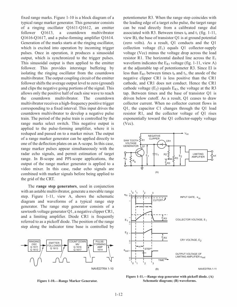
• Azimuth Range Indicator IP-1342/APS-130 or
IP-1342B/APS-130
• Azimuth Elevation Range Indicator
IP-1060A/APQ-148
• Antenna-Receiver AS-3325/APS-130
• Power Supply PP-6574/APQ-148
O-1778/APS-130 REFERENCE SIGNAL
GENERATOR (RSG)
The Reference Signal Generator O-1778/APS-130
(RSG) provides a crystal-controlled clock and digital
timing loop to generate PRF trigger, sweep triggers,
range markers, and precision range line signal. Figure
1-19 provides the physical location of the RSG in the
aircraft and a visual representation of the unit. The RSG
provides for vertical and horizontal sweeps, intensity
gates, and video for the DVRI and PHD during all
modes of operation of the DVRI and PHD. The BIT
capability, which is selectable on the radar control
panel, verifies the operation. The BIT capability, which
is selectable on the radar control panel, verifies the
operation of the RSG.
The RSG is divided into the following functional
groups: synchronization and timing group, precision
range line (PRL) generation group, video selection
mixing group, sweep group, and bit group.
The synchronization and timing group receives
inputs from the antenna receiver (A/R) and radar
control panel (RCP), and provides timing and control
signals for the operation of the radar set.
The PRL generation group receives inputs from the
analog digital-digital analog converter (ADDAC) and
provides the PRL range markers, the pulldown signal,
and the sweep start trigger.
The video selection and mixing group combines
video with azimuth and range markers for processing
by the azimuth range indicator (DVRI) and azimuth
elevation range indicator (PHD). Range and azimuth
marker brightness signals from the RCP and display
control panel (DCP) control the brightness signals from
the RCP and display control panel (DCP) control the
brightness (intensity) of the range and azimuth markers
that are mixed with the video signals.
The sweep group demodulates azimuth, vertical,
and horizontal synchro information, provides selection
and scaling for the plan position indicator (PPI)
horizontal and vertical sweeps, generates timing
signals that relate to azimuth, and generates intensity
gates and intensity compensation sweeps that control
the presentation of video returns.
The BIT group provides an operational status
indication to the RCP. The three major output of the
BIT group supplied to the RCP are used to monitor
functionally all RSG circuits.
T-1396/APS-130 RADAR TRANSMITTER
Figure 1-20 shows the T-1396/APS-130
Transmitter and its position within the aircraft. The
radar transmitter/modulator (T/M) provides
high-energy microwave pulses of fixed width and fixed
repetition rate, and whose RF frequency can be
continuously adjusted for radiation by the antenna
receiver. The T/M generates high-voltage negative
pulses of required amplitude at a pulsewidth and
repetition frequency determined by the system. The
pulses are stepped up to an amplitude required to fire
the magnetron. When the magnetron fires, it generates
1-18
AEf02019
K
K
Figure 1-19.—O-1778/APS-130 Reference Signal Generator
(RSG) position in aircraft.

high-energy RF power that is applied to the wave guide
section for transmission to the antenna/receiver
antenna for radiation. The T/M is divided into four
functional groups: power supply group, modulator
group, transmitter group, and BIT group.
C-10535/APS-130 RADAR SET CONTROL (RCP)
The Radar Set Control C-10535/APS-130 (RCP) is
at the ECMO 1 station on the forward right pedestal. It
provides all the manual controls for coordinating
functions of the search radar, for adjusting the DVRI
display, and for selections and displaying the results of
BIT. A detailed description of the controls and
indicators shown in figure 1-21 follows:
1. MAG FREQ. The MAG FREQ indicator is a
three lamp indicator that monitors the magnetron
operating frequency range and displays whether the
magnetron is operating in HIGH, MID, or LOW
frequency range.
2. TILT. The TILT is a rotary control knob
adjustable over 270° with a locking device and detent
position. It adjusts the tilt (pitch) angle from 12° tilt
down to 4° tilt up.
3. RNG MKR. The RNG MKR is a rotary
control knob adjustable over 312°. It varies the
brightness level of the DVRI range markers.
4. AZ MKR. The AZ MKR is a rotary control
knob adjustable over 312°. It varies the brightness level
of the DVRI azimuth markers.
5. SCAN STAB. The SCAN STAB is a
two-position rotary selected switch that allows
selection of either of two antenna stabilization
references. In the ADL position, the antenna scan is
stabilized about the aircraft datum line (ADL). The
DVRI display will be centered about the ADL. In the
REL BRG position, the antenna scan is stabilized about
the azimuth cursor, which may be positioned at any
point from 0° to ± 55° relative bearing with respect to
the ADL. The DVRI display will be centered about the
azimuth cursor position.
6. SCAN ANGLE. The SCAN ANGLE is a
rotary control knob adjustable over 320° that provides a
means of adjusting the antenna scan angle for any value
from ± 10° to ± 55° about the selection scan
stabilization center.
7. CONTRAST. The CONTRAST is a rotary
control knob adjustable over 312°, which controls the
DVRI video amplifier gain.
1-19
AEf02020
J
J
Figure 1-20.—T-1396/APS-130 Transmitter location in
aircraft.
AEf02021
RADAR
MAG FREQ
TILT
SCAN STABSCAN ANGLE
RELBRG
ADL
CONTRASTBRT
PWR
XMIT
OFF
BIT/STBY
VIDEO GAIN
BIT
SSE
30
NO
50
15
25
-12 +4
0
STOP
DECR
INC
HIGH
MID
LOW
75150
100
00
PED
T/M
RCVROFF
RCP
LVPS
RSG
RFPWR
PPI RNG
SCAN SPD
ORCVRGAINSTC OP
ORNG MKRAZ MKR
o
oo
1 2
3
4
5
6
7
8
91011
12
13
14
15
16
17
Figure 1-21.—Radar Control Panel - Controls and Indicators.

8. BRT. The BRT is a rotary control knob
adjustable over 312°, which sets the brightness level of
the DVRI raster.
9. PWR. The PWR is a three position
lever-locked switch (without RAMEC P-27-82
installed) and a three position, detented, lever-locked
switch (with RAMEC P-27-82 installed) that controls
the application of aircraft power to the radar set. In the
OFF position, the radar is completely de-energized, and
the raster does not appear on the DVRI. In the
BIT/STBY position, low-voltage power is applied to all
WRAs and to tube filaments. The BIT function is
enabled, high voltage is not applied to the transmitter,
and raster and markers appear on the DVRI. In the
XMT position, high voltage is applied to the transmitter
after a 5-minute time delay, making the radar
completely operational. The DVRI will display raster,
markers, and video.
10. VIDEO GAIN. The VIDEO GAIN is a rotary
control knob adjustable over 312°, which allows the
operator to enhance the displayed characteristics of a
simple target or a group of targets.
11. BIT. The BIT is a nine-position rotary selector
switch that allows selection of component BIT status
signals to be monitored. The positions are:
• OFF - No bit status signal is monitored.
• RCP - Radar Control Panel BIT status is
monitored.
• LVPS - Low Voltage Power Supply BIT
status is monitored.
• RSG - Reference Signal Generator BIT sta-
tus is monitored.
• SSE - Antenna/Receiver scan servo elec-
tronics BIT status is monitored.
• PED - Antenna/Receiver pedestal BIT sta-
tus is monitored.
• T/M - Transmitter/Modulator BIT status is
monitored.
• RF PWR - Antenna/Receiver rf power BIT
status is monitored.
• RCVR - Antenna/Receiver BIT status is
monitored.
12. NO/GO. The NO/GO consists of two lamps
that illuminate to indicate to the operator when there is
a BIT failure.
13. PPI RNG. The PPI RNG is a four-position
rotary selector switch that permits the selection of
different PPI sweep ranges from the DVRI and PHD.
The selector positions are:
• 15—Selects 15 nmi PPI sweep range.
• 30—Selects 30 nmi PPI sweep range.
• 75—Selects 75 nmi PPI sweep range.
• 150—Selects 150 nmi PPI sweep range.
14. RCVR GAIN. The RCVR GAIN is a rotary
control knob adjustable over 312° that, in conjunction
with the BRT and CONTRAST controls, provides
adjustment of the receiver gain to intensify the targets
presented on the DVRI and PHD display.
15. STC DP. The STC DP is a rotary control knob
adjustable over 312° that provides a means of reducing
the gain level of video returns from close-in targets in
order to prevent blooming.
16. SCAN SPD. The SCAN SPD is a four-position
rotary selector switch that provides a means of
selecting the antenna scan speed. The positions are
OFF, 25, 50, and 100. The OFF position holds the
antenna at the selected SCAN STAB position. The 25
position selects the 25°/second antenna speed, the 50
position selects the 50°/second antenna speed, and the
100 position selects the 100°/second antenna speed.
17. MAG FREQ-INC/DECR. The MAG
FREQ-INC/DECR is a three-position toggle switch
spring-loaded to the center (OFF) position. When the
INC position is selected, it increases the magnetron
frequency; and when the DECR position is selected, it
decreases the magnetron frequency.
C-7588A/APQ-129 CURSOR CONTROL
The Cursor Control C-7588A/APQ-129 (fig. 1-22),
also known as the slew control, is used to check or
update the precomputed target or navigation data while
operating the search radar in search mode. Two slew
control(s) permits the slewing of range and azimuth
cursors on the pilot’s horizontal display (PHD), Radar
Display Indicator IP-691A/APQ-129, or on the radar
operator’s direct view range indicator (DVRI). Each
slew control provides manually controlled signals for
updating of target coordinates. Repositioning of range
and azimuth lines at the PHD and DVRI provides visual
verification of target coordinates updating. During
updating, the ECMO 1 slew control has priority for all
inputs.
1-20
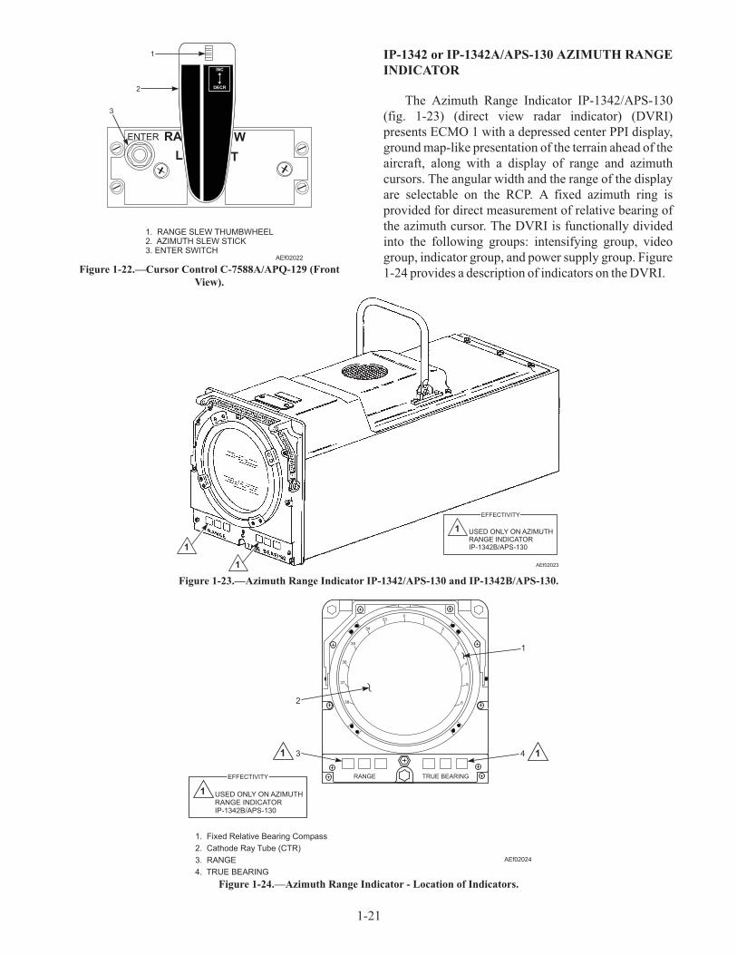
IP-1342 or IP-1342A/APS-130 AZIMUTH RANGE
INDICATOR
The Azimuth Range Indicator IP-1342/APS-130
(fig. 1-23) (direct view radar indicator) (DVRI)
presents ECMO 1 with a depressed center PPI display,
ground map-like presentation of the terrain ahead of the
aircraft, along with a display of range and azimuth
cursors. The angular width and the range of the display
are selectable on the RCP. A fixed azimuth ring is
provided for direct measurement of relative bearing of
the azimuth cursor. The DVRI is functionally divided
into the following groups: intensifying group, video
group, indicator group, and power supply group. Figure
1-24 provides a description of indicators on the DVRI.
1-21
AEf02022
ENTER
L T
RA W
INC
DECR
3
1
2
1. RANGE SLEW THUMBWHEEL2. AZIMUTH SLEW STICK3. ENTER SWITCH
Figure 1-22.—Cursor Control C-7588A/APQ-129 (Front
View).
AEf02023
1
1
1 USED ONLY ON AZIMUTHRANGE INDICATORIP-1342B/APS-130
EFFECTIVITY
Figure 1-23.—Azimuth Range Indicator IP-1342/APS-130 and IP-1342B/APS-130.
01
2
3
4
5
638
37
36
35
34
33
RANGE TRUE BEARING
AEf02024
1 1
1 USED ONLY ON AZIMUTHRANGE INDICATORIP-1342B/APS-130
EFFECTIVITY
1. Fixed Relative Bearing Compass
2. Cathode Ray Tube (CTR)
3. RANGE
4. TRUE BEARING
1
4
2
3
Figure 1-24.—Azimuth Range Indicator - Location of Indicators.

IP-1060A/APQ-148 AZIMUTH ELEVATION
RANGE INDICATOR
The Azimuth Elevation Range Indicator
IP-1060A/APQ-148 (pilot’s horizontal display) (PHD)
relays to the pilot a duplicate display of the DVRI
presentation of the terrain ahead of the aircraft. The
angular width and the range of the display are selected
on the RCP. The PHD also includes electromechanical
indicators that permits the pilot to determine aircraft
heading and relative drift corrected steering. A Direct
View Storage Tube (DVST) is used to provide a display
that may be viewed in broad daylight.
The PHD itself has no operating controls, however,
the front panel does contain indicators described in
table 1-2 and shown in figure 1-25.
AS-3325/APS-130 ANTENNA-RECEIVER
The Antenna-Receiver AS-3325/APS-130 (A/R) is
a pitch-and-roll stabilized unit that provides the means
of radiating energy from the T/M and of receiving
reflected microwave energy. The A/R is in the nose of
the fuselage, with the antenna dish and front feed horn
on a scan column. Attached to the bottom of the scan
column is the search receiver electronics unit. Toward
1-22
INDICATOR FIGURE 1-25 INDEX NO. INDICATION FUNCTION
Time 1 Command heading is indicated by position of
movable pointer on compass rose.
Compass rose and pointer 2 True heading of aircraft is indicated by position
of movable compass: rose under fixed painter
at top center of DVST screen.
RANGE 3 Displays ground range to a selected target in
nautical miles (not used in APS-130).
Direct View Storage Tube
(DVST)
4 Displays radar and test pattern information.
ELAPSED TIME meter on
right side
5 Indicates total accumulated time (in hours) that
the prime power has been applied to the PHD.
Table 1-2.—Indicators
AEf02025
12
3
4
5
Figure 1-25.—PHD Indicators.

the top rear of the scan column is the scan and
stabilization electronics unit. Access to the A/R is
gained by raising the nose radome (fig. 1-26).
The scan power drive assembly develops the
necessary drive power to drive the antenna alternately
in a clockwise and counterclockwise direction to
perform the scanning function. The assembly contains
a motor tachometer and a cooling fan.
Scan drive excitation power is applied to the motor
section of the motor-tachometer. The polarity of the
input determines the direction of rotation of the motor
tachometer, and thus of the antenna scan. To make
certain that the antenna scan rate is maintained at the
desired speed, the scan tach feedback, which represents
the actual speed of the antenna scan, from the
tachometer portion of the motor-tachometer is fed back
to the scan electronics amplifier assembly. The
electronics amplifier assembly is part of the scan and
stabilization electronics assembly, where the scan tach
feedback is summed with the desired scan rate.
A capacitor (C1) provides the proper phase-shift
angle between the fixed-phase and control-phase
windings angle between the fixed-phase and
control-phase windings of the motor-tachometer. The
cooling fan, powered by the 115 Vac, 400 Hz, 3-phase
power, provides the necessary cooling of the scan
power drive assembly.
The pitch power drive assembly develops the
necessary drive power to drive the antenna in the
direction necessary to correct the antenna position due
to aircraft deviation from the horizontal. The assembly
contains a motor-tachometer and a brake clutch.
The pitch drive excitation power is applied to the
motor section of motor-tachometer. The polarity of the
input determines the direction of rotation of the
motor-tachometer, and thus of the antenna. To make
1-23
AEf02026
SCAN AND STABILIZATIONELECTRONICS UNIT
(75A1A2)
ANTENNARECEIVER
(75A1)
SEARCH RECEIVERELECTRONICS UNIT
(75A1A1)
LOW VOLTAGEPOWER SUPPLY
(75A4)
PITCH POWERDRIVE ASSEMBLY
(75A1A6)
FWD
PURGEVALVE
SCAN ANDSTABILIZATIONELECTRONICS
ASSEMBLY(75A1A2)
SCAN POWERDRIVE ASSEMBLY
(75A3)
CAPACITOR(A3C1)
FREEDHORNASSEMBLY
DISH
G
F
HROTATED 180o
Figure 1-26.—AS-3325/APS-130 Antenna-Receiver.

certain that the antenna maintains constant corrective
speed, the pitch tach feedback from the tachometer
portion of the motor-tachometer is fed back to the pitch
electronics amplifier.
The pitch electronics amplifier is part of the scan
and stabilization electronics assembly, where the pitch
tach feedback is either summed or subtracted from the
pitch error signal to maintain proper pitch corrective
speed. A capacitor (A6C1) provides the proper
phase-shift angle between the fixed-phase and
control-phase windings of the motor-tachometer.
The BIT switch on the RCP has positions marked
SSE, PED, RF PWR, and RCVR that provide go/no-go
checks and fault isolation of the components of the
A/R.
PP-6574/APQ-148 POWER SUPPLY
The power supply PP-6574/APQ-148 (low-voltage
power supply) (LVPS) controls the application of
aircraft power (115 Vac, 400 Hz, three-phase and 28
Vdc) supplied to the radar, and rectifies, regulates, and
supplies all low-voltage power to the search radar
WRAs. Selection of LVPS on the radar control panel
BIT switch provides a GO/NO-GO check of the LVPS.
Cold plate heat exchangers are used with forced air
cooling provided by the aircraft environmental control
system to satisfy the cooling requirements of the LVPS.
See figure 1-27.
Q1-30. What are the four positions on the SCAN SPD
rotary switch on the C-10535/APS-130 Radar
Set Control?
Q1-31. What are the four functional groups of the
T-1396/APS-130 Transmitter?
Q1-32. What position is the DVRI located in?
Q1-33. The CV-2434 Analog-Digital Converter is a
major component of what radar system?
Q1-34. During update mode, what slew control has
priority for all inputs?
1-24
AEf02027
Figure 1-27.—PP-6574/APQ-148 power supply.

CHAPTER 2
IDENTIFICATION FRIEND OR FOE (IFF) SYSTEMS
INTRODUCTION
With the destructive power of modern weapon
systems and the speed of modern weapon delivery
systems, it is not always practical to wait until a
detected radar target has been identified by visual
means before preparing for battle. Therefore, a means
of identifying friendly targets from enemy targets at
long range is necessary. It was this need that brought
about the advent of the IFF system. The IFF
system provides automatic identification friend or foe
(IFF) of an air or surface vehicle to all IFF
interrogator-equipped aircraft, ships, and ground forces
within the operating range of the system. IFF systems
also provide other information, such as type of craft,
squadron, side number, mission, and aircraft altitude.
GENERAL THEORY OF OPERATION
LEARNING OBJECTIVE: Recognize gen-
eral operating principles, components, charac-
teristics, and maintenance concepts of typical
airborne IFF systems.
IFF completes the identification process in three
basic steps: (1) challenge, (2) decode, and (3) reply. A
simplified block diagram of a typical IFF system is
shown in figure 2-1. The system is comprised of an
interrogator (challenging unit) and a transponder (reply
unit). The interrogator interfaces physically with the
radar system in which its operations (transmissions and
receptions) are synchronized. When radar contacts of
interest are interrogated, the transponder unit of the
interrogated aircraft replies to the challenges and
provides the proper coded response, which, in turn,
indicates the challenged contact is friendly. Responses
not incorporating the proper identification codes are
interpreted as coming from hostile units. All naval
aircraft contain a transponder set; however, an
interrogator set is installed only in platforms that have a
need to interrogate and identify aircraft from a distance
for tactical purposes.
2-1
Note: Interrogation plat form also containsa transponder system.
AntennaArray
ComputerDecoder
RadarDisplay
ControlPanel
Receiver Transmitter
INTERROGATOR
AntennaArray
ComputerDecoder
Receiver Transmitter
TRANSPONDER
Coded
Challenges
Coded
Replies
AE/ATf2-01
Figure 2-1.—IFF system block diagram.
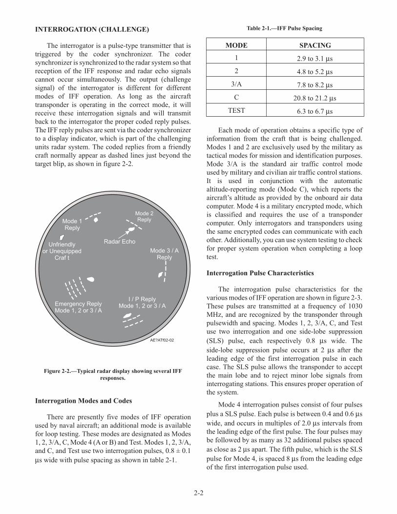
INTERROGATION (CHALLENGE)
The interrogator is a pulse-type transmitter that is
triggered by the coder synchronizer. The coder
synchronizer is synchronized to the radar system so that
reception of the IFF response and radar echo signals
cannot occur simultaneously. The output (challenge
signal) of the interrogator is different for different
modes of IFF operation. As long as the aircraft
transponder is operating in the correct mode, it will
receive these interrogation signals and will transmit
back to the interrogator the proper coded reply pulses.
The IFF reply pulses are sent via the coder synchronizer
to a display indicator, which is part of the challenging
units radar system. The coded replies from a friendly
craft normally appear as dashed lines just beyond the
target blip, as shown in figure 2-2.
Interrogation Modes and Codes
There are presently five modes of IFF operation
used by naval aircraft; an additional mode is available
for loop testing. These modes are designated as Modes
1, 2, 3/A, C, Mode 4 (A or B) and Test. Modes 1, 2, 3/A,
and C, and Test use two interrogation pulses, 0.8 ± 0.1
µs wide with pulse spacing as shown in table 2-1.
Table 2-1.—IFF Pulse Spacing
MODE SPACING
1 2.9 to 3.1 µs
2 4.8 to 5.2 µs
3/A 7.8 to 8.2 µs
C 20.8 to 21.2 µs
TEST 6.3 to 6.7 µs
Each mode of operation obtains a specific type of
information from the craft that is being challenged.
Modes 1 and 2 are exclusively used by the military as
tactical modes for mission and identification purposes.
Mode 3/A is the standard air traffic control mode
used by military and civilian air traffic control stations.
It is used in conjunction with the automatic
altitude-reporting mode (Mode C), which reports the
aircraft’s altitude as provided by the onboard air data
computer. Mode 4 is a military encrypted mode, which
is classified and requires the use of a transponder
computer. Only interrogators and transponders using
the same encrypted codes can communicate with each
other. Additionally, you can use system testing to check
for proper system operation when completing a loop
test.
Interrogation Pulse Characteristics
The interrogation pulse characteristics for the
various modes of IFF operation are shown in figure 2-3.
These pulses are transmitted at a frequency of 1030
MHz, and are recognized by the transponder through
pulsewidth and spacing. Modes 1, 2, 3/A, C, and Test
use two interrogation and one side-lobe suppression
(SLS) pulse, each respectively 0.8 µs wide. The
side-lobe suppression pulse occurs at 2 µs after the
leading edge of the first interrogation pulse in each
case. The SLS pulse allows the transponder to accept
the main lobe and to reject minor lobe signals from
interrogating stations. This ensures proper operation of
the system.
Mode 4 interrogation pulses consist of four pulses
plus a SLS pulse. Each pulse is between 0.4 and 0.6 µs
wide, and occurs in multiples of 2.0 µs intervals from
the leading edge of the first pulse. The four pulses may
be followed by as many as 32 additional pulses spaced
as close as 2 µs apart. The fifth pulse, which is the SLS
pulse for Mode 4, is spaced 8 µs from the leading edge
of the first interrogation pulse used.
2-2
Mode 1Reply
Mode 2Reply
Radar EchoUnfriendly
or UnequippedCraf t
Mode 3 / AReply
I / P ReplyMode 1, 2 or 3 / AEmergency Reply
Mode 1, 2 or 3 / A
AE?ATf02-02
Figure 2-2.—Typical radar display showing several IFF
responses.

TRANSPONDER (REPLY)
The IFF transponder is a receiver/transmitter
combination, which automatically replies to coded
challenges when Mode decoding is satisfactory. The
receiver section identifies the interrogation Mode by
decoding the spacing between P1 and P3 (for Modes 1,
2, 3/A, C, and Test) and comparing P2 (SLS) with the
main lobe pulses P1 and P3. If the SLS control pulse is at
least 9 dB less than P1 or P3, the interrogator pulse train
is evaluated and decoded as being in a main lobe, which
automatically keys the transmitter section to send a
prearranged reply signal at a frequency of 1090 MHz. If
not, it is evaluated and decoded as being in a side lobe,
and the transponder system disables any reply response
to such an interrogation.
Modes 1, 2, 3/A, and Test IFF replies use
selective-identification-function (SIF) encoding.
SIF/IFF codes are octal numbers that consist of three
binary bit positions. A standard SIF reply (fig. 2-4) has
2-3
*
0 1 2 3 4 5 6 7 8 9 10 11 12 13 14 15 1617 18 19 20 21 22232425 26
Time
(In )s
Mode 1P
3
P3
P3
P3
P3
Mode 2
Test Mode
Mode 3/A
Mode C
Mode 4
- Side lobe suppression pulse (SLS).
(1) - Not present when testing with simulated input.(2) - SLS pulse may be followed by as many as 32 pulses.
Spaced at 2 s intervals.
P1P
2
P
P
P
P
P P
1
1
1
1
1 3
P
P
P
P
P P
2
2
2
2
2 4
*
*
*
*
*
*
(1)
(2)
AE/ATf02-03
Figure 2-3.—IFF interrogator pulse characteristics.
0 1 2 3 4 5 6 7 8 9 10 11 12 13 14 15 1617 18 19 20 21 22232425 26
Time
(In )s
Mode 1
Mode 2, 3/Aand Test
Mode C
Mode 4
Note:F and F pulses are reply framing pulses.
* Reply occurs between 200 and 270 us after a mode 4 trigger
F
F
F
C
C
F
F
F
A
A
A
C
C
A
A
A
C
C
B
B
B
D
B
B
B
B
B
D
D
D
D
1
1
1
1
1
2
2
2
A
A
A
P4
4
*
1
1
1
2
2
2
2
2
4
4
4
4
4
1
1
1
1
1
2
2
2
2
4
4
2
2
4
4
1.75 us 1.75 us
AE/ATf02004
Figure 2-4.—IFF transponder reply pulse characteristics.

provisions for four octal characters (A, B, C, and D)
and is bounded by two framing (bracket) pulses (F1 and
F2). The seventh bit position, between bit position A
and B, is designated X. Bit position X is not part of any
octal character and is logical 0 in any standard reply.
Mode 1 uses only octal characters A (A4-A2-A1)
and two least significant bit positions of character B
(B2-B1) to represent a code range from 00 to 73
(rendering 32 possible combinations). Modes 2 and 3/A
use all four octal characters (A, B, C, D) to represent a
code range from 0000 to 7777 (4,096 possible
combinations are capable). Mode 1 is set by two
pushbutton switches or thumbwheels (depending on
the model of IFF system being used), Mode 3/A is set
by four switches, while Mode 2 (four switches) is
preset prior to flight by maintenance personnel. Mode
C reply uses the same standard format as a SIF reply,
except that bit position D1 is not used, which allows for
a total of 2,048 possible codes. Mode 4 replies are
generated by the transponder computer and sent to the
transponder receiver/transmitter for RF transmission as
three-pulse, time-coded reply. A valid Mode 4 exists if
the Mode 4 reply rate and transmission are satisfactory.
Mode 4 reply pulse coding is accomplished by crypto
equipment and is classified information. This
information can be found in technical manuals for the
KIT-1/TSEC equipment.
The operation of the interrogated aircraft's
transponder (mode of operation and specific codes,
etc.) are controlled by a panel (depending on IFF
system) similar to the one shown in figure 2-5. This
panel contains switches, code selectors, lights, and
operational modes.
MASTER Control Switch
The MASTER control switch is a four position
rotary switch used to select the operating condition. In
the STBY position, power is applied to the IFF coder,
but interrogations are inhibited. In the NORM position,
the transmitter-receiver is enabled for normal
sensitivity. In the EMER position, the IFF coder
transmits emergency replies to interrogations in Modes
1, 2, or 3/A. The Mode 3/A emergency reply includes
code 7700. With EMER selected, Mode 4 is enabled
regardless of the position of the Mode 4 switch, and
Mode C continues to function normally if selected. To
select the EMER position, pull the control outward and
rotate to the EMER position.
IDENT/OUT/MIC Switch
The IDENT/OUT/MIC switch is a three-position
toggle switch that is spring-loaded to return to the OUT
position, which controls the transmission of the
Identification of Position (IP) pulse. It is used in
conjunction with Modes 1, 2, and 3/A to identify a
specific friendly aircraft among other friendly aircraft
that reply with the correct code. When the switch is
2-4
DIMPR
ES
S TO TES
T
DIMPR
ES
S TO TES
T
DIMPR
ES
S TO TES
T
A
B
HOLD
ZERO
EMER
NO
RM
ST
BYOFF
TEST AUDIO REPLY
OUT OUT
ON
ON
ON
LIGHT
MODE 3/AMODE 1
OUT
RADTEST
STATUS
ALT KIT ANT
IDENT
OUT
ANT
M-1 M-2 M-VA M-CTEST
OUT
CODE
NO
OO GO
MIC
DIV
TOP MASTER
BOT
TEST/MONTEST
IFF
MODE 2 MODE 2
4 1 7 4 7 1
MODE 4
AE/ATf02-04
Figure 2-5.—Typical IFF transponder set control box.

momentarily set to the IDENT position, the IFF coder
adds an identification of position response to Modes 1,
2, and 3/A for 15 to 30 seconds. In the MIC position, the
identification of position function is activated for 15 to
30 seconds whenever the microphone switch is
actuated. In the OUT position, the IDENT reply is
disabled.
Modes 1, 2, and 3/A Code Selectors
Four eight-position push-button switches are
provided for selection of Modes 2 and 3/A, while Mode
1 has one eight-position and one four-position
push-button switch for selection of a particular code to
be transmitted. The Mode 2 reply code setting is set by
the maintenance person prior to flight by loosening the
Mode-2 screws on the front panel of the transponder
receiver/transmitter and sliding the plate up. The proper
code is then set by using the four Mode 2 push-button
switches. The plate is then returned to its normal
position and the screws are retightened.
Mode-Selector Test Switches and Lights
Four three-position toggle switches, labeled
"M-1," "M-2," "M-3/A," and "M-C", are used for
selecting the proper mode of operation. Placing anyone
of the switches to ON selects that mode for
transmission. By placing the switch to OUT, it
de-selects the mode of operation; and by placing the
switch to TEST, it initiates the built-in test (BIT)
operation for that mode. As a result, a Mode 1, 2, 3/A,
or C test enable signal is applied to the bit control
circuits in the transponder-transmitter, which enables
generation of a test signal of proper parameters. If the
parameters are found satisfactory, the TEST GO
indicator light will illuminate on the transponder
receiver/transmitter control panel. An error causes the
TEST/MON NO-GO indicator light to illuminate,
indicating a malfunction has occurred.
RAD TEST/OUT Switch
The RAD TEST/OUT switch is a two-position
toggle switch that is spring-loaded to the OUT or
(down) position. When RAD TEST is selected, the
system responds to TEST mode interrogations from a
test set during ground maintenance testing.
Mode 4 Operation
The Mode 4 controls and indicator light are
grouped across the center of the control panel. The
MASTER rotary switch controls transponder operation
in Mode 4 as well as in the other modes of operation.
Mode 4 will operate normally, when selected, in either
the NORM or EMER position. The Mode 4 function
will be inoperative in either the STBY or OFF position.
With the transponder functioning, Mode 4 operation is
selected by placing the 3-position Mode 4
TEST-ON-OUT toggle switch to ON. Placing the
switch to OUT disables Mode 4 operation, and placing
it to TEST enables the BIT operation.
The Mode 4 CODE control selects either of the two
(A or B) Mode 4 codes that are stored in the classified
transponder computer. The rotary switch has two
additional positions, HOLD and ZERO. At a
designated daily time and/or prior to the day's mission,
maintenance personnel electronically load the Mode 4
codes into the transponder computer. The present code
period is placed in position A, and the code for the
succeeding code period is placed in position B. Both
code settings will automatically zeroize when power is
turned off or lost after the landing gear interlock switch
supplies a ground signal to the computer. Activating the
HOLD function will retain the code settings. This is
normally done while the aircraft is landing, and before
power is removed from the transponder. Place the
Mode 4 CODE control to HOLD, and release. Allow
transponder power to remain on for at least 15 seconds,
and then turn it off. The code setting will be retained
when aircraft power is turned off.
With aircraft power on and the MASTER rotary
switch in any position except OFF, both code settings
can be zeroized at any time by placing the CODE
switch to the ZERO position. Both code settings will
also be zeroized if the HOLD function has not been
properly actuated before the MASTER switch is turned
to OFF. (Inadvertent selection of OFF is prevented by
switch design, which requires that the rotary knob be
pulled out before it can be turned to OFF.) When the
CODE switch is placed in the A position, the aircraft
transponder will respond to Mode 4 interrogations from
an interrogator using the same code setting as that set
into the aircraft's code A position. In the B position,
interrogations from an interrogator using the same code
setting as that set into the aircraft's code B position will
be answered. The changeover time from code A to code
B use is operationally directed.
The Mode 4 AUDIO/LIGHT/OUT switch selects
the aircraft indication for Mode 4 replies. In the LIGHT
position, the Mode 4 REPLY lamp will light when a
correct Mode 4 reply is transmitted. In the AUDIO
position, an IFF transponder caution tone will be heard
2-5

in the pilot’s headset if an unidentified Mode 4
interrogation is received. In the OUT position, both
light and audio indications are inoperative.
Transponder Special Reply Functions
The transponder may transmit replies in four
special modes: the emergency mode; the identification
of position (I/P) mode; the X-pulse mode, which is used
in Modes 1, 2, and 3/A; and the altitude special position
identification (SPI) used with Mode C replies. Mode 4
is not affected by the special reply functions. Refer to
figure 2-6 for the special replies generated for these
special features.
EMERGENCY REPLY.—Setting the MASTER
selector switch to EMER controls the emergency mode
of operation of the transponder. This condition is
initiated when the operator has an onboard emergency
or has ejected from the aircraft. The emergency
function affects the operation of Modes 1, 2, and 3/A. In
Modes 1 and 2, the reply pulse train containing the code
in use is transmitted once for each interrogation pulse
received, followed by three sets of framing pulses and
no information pulses. For each interrogation pulse
received in Mode 3/A, one reply pulse train containing
the code 7700 (regardless of the Mode 3 control dial
settings) is transmitted, followed by three sets of
framing pulses and no information pulses. The framing
pulses are spaced in the same manner as Modes 1 and 2.
During the emergency function the IFF transponder
system replies to interrogations in Modes 1, 2, and 3/A
automatically, regardless of which mode is enabled on
the receiver/transmitter. By referring back to figure 2-2,
the interrogating source radar screen should show four
display bars or markers behind the target instead of just
one row as in normal operation.
IDENTIFICATION OF POSITION (I/P).—The
I/P function is controlled by the IDENT/OUT/MIC
switch and affects the operation of Modes 1, 2, and 3/A.
Upon radio request from an interrogating source, the
I/P operation is selected by placing the transponders
IDENT-OUT-MIC switch momentarily to IDENT,
which forces the reply into an I/P format. In Mode 1, the
reply pulse train containing the code in use is
transmitted twice, instead of once, for each
interrogation pulse received. In Modes 2 and 3/A, the
reply pulse train containing the code in use is
transmitted once, followed by a special position
indicator (SPI) pulse for each interrogation pulse
received. The result of the extra pulse train in Mode 1
and the SPI pulse in Modes 2 and 3 can be seen in figure
2-6. At the interrogating source radar screen, an IFF
reply display with an I/P reply is differentiated from
standard IFF reply displays by two display bars or
markers appearing behind the target, as shown in figure
2-2. This mode is useful when the desired aircraft is in
the vicinity of other aircraft using the same coding.
X-PULSE.—The X-pulse appears following the
initial framing pulse in the normally unused position of
Modes 1, 2, and 3/A. It can only be obtained by
modifying the controls. When modified, all replies in
Modes 1, 2, and 3/A will include this pulse, along with
the normally selected information reply pulses,
between the two framing pulses. To date, the use of this
pulse has been used to identify “special” status, such as
an unmanned or experimental aircraft.
2-6
012
345
10 30 35 40 4515 50 55 60 6520 70 75 80 8525 90 95
Time
(In )s
Mode1 & 2
F3
F3
F3
F4
F4
F4
F5
F5
F6
F6
F7
F7
F8
F8A B4 4
X
SP1
SP1
Mode3/A
Mode1
Normal Reply
Normal Reply Normal Reply
Normal Reply
Normal Reply
ReplyNormal
Mode2 & 3/A
X PulseMode 1, 2& 3/A
SP1Mode C
F1
F
F
F
F
F
1
1
1
1
1
F2
F2
F2
F2
F2
D4 F
2
A B1 1A B2 2
Identificationof Position
Emergency
AE/ATf02-06
Figure 2-6.—Special reply pulse characteristics.

SPECIAL POSITION IDENTIFICATION
(SPI) PULSE.—The SPI pulse is generated whenever
a D4 pulse is used in a Mode C reply. This pulse is in the
same position as the initial framing pulse of a second
reply train, F3. The SPI mode is used with Mode C
replies to assist the operator at the challenging station to
segregate aircraft above or below an altitude of
approximately 31,000 feet.
IFF MAINTENANCE CONCEPTS
IFF systems are designed for rapid recognition of
hardware failures, ease in replacement of the unit,
accuracy of fault isolation, and ease of board and
module replacement and repair. Built-In-Test (BIT)
circuits are used to verify system readiness and perform
fault isolation to the failed Weapons Replaceable
Assembly (WRA).
Corrective maintenance consists of trouble-
shooting, removal, and replacement of WRAs. The BIT
features are used to perform fault isolation to failed
WRA in most cases. External confidence checks are
performed using the AN/APM-424(V)2 (Star Wars
Gun) transponder test set, shown in figure 2-7. This test
set performs a radiated test on the aircraft transponders
system to verify proper operation of Modes 1, 2, 3/A, C,
and 4. When a failure in the transponder system occurs,
the test set displays a coded digit to assist the operator
in fault isolation of the system.
Q2-1. What does the acronym IFF stands for?
Q2-2. What are the three basic steps in the iden-
tification process of a typical IFF system?
Q2-3. True or False. All naval aircraft contain an
interrogator system.
Q2-4. What is the pulse spacing of Mode 1?
Q2-5. Of the six modes of IFF operation, which one
is used by military and civilian aircraft
control stations?
Q2-6. What mode IFF is the military encrypted
mode?
Q2-7. What is the transmission frequency of the
interrogator?
Q2-8. In a typical IFF/SIF system, what total
number of codes can be selected in Mode 2?
Q2-9. The Identification of Position (I/P) pulse is
used for what purpose?
Q2-10. What mode of IFF is set prior to takeoff by
maintenance personnel?
TRANSPONDER AND
INTERROGATOR SETS
LEARNING OBJECTIVE: Recognize the
components of the Transponder Set
A N / A P X - 7 2 , I n t e r r o g a t o r S e t
AN/APX-76(V), and Transponder Set
AN/APX-100(V).
Components of Transponder Set AN/APX-72,
Interrogator Set AN/APX-76, and Transponder Set
AN/APX-100(V) are discussed here.
TRANSPONDER SET AN/APX-72
The AN/APX-72 transponder set generates and
transmits a 1090 MHz reply signal only upon receipt
and successful validation of an interrogation signal.
Although the IFF transponder system is capable of
responding to interrogations in any of the five modes of
operation, it responds only if the operator has manually
enabled a particular mode. The five major components
of the AN/APX-72 are discussed here.
RF TRANSMISSION LINE SWITCH
SA-1769/A. The RF transmission switch (fig. 2-8)
2-7
AE/ATf02-07
Figure 2-7.—AN/APM-424(V)2 transponder test set.
ANT2
J4
J3
J1
J2
COM
ANT1
AE/ATf02008
Figure 2-8.—SA-1769/A RF transmission line switch.

couples interrogations and replies between two UHF
L-band antennas and the transponder set. The switching
between the antennas operates at approximately 38 Hz.
This switching action prevents the antenna system from
being blanked out during aircraft maneuvers.
T R A N S P O N D E R S E T C O N T R O L
C-6280/APX-72. The IFF control box (fig. 2-9)
contains controls and indicators used for system
operation and manual testing. Reply codes for Modes 1
and 3/A are selected with panel-mounted thumbwheel
switches. These codes can be inserted or changed
during flight, while Mode 2 and Mode 4 codes must be
preset before takeoff.
RECEIVER/TRANSMITTER RT-859/APX-72.
The receiver/transmitter (fig. 2-10) will transmit a reply
when RF interrogations are received from an IFF
interrogator. The unit receives coded interrogations at
1030 MHz and transmits code replies at 1090 MHz.
The transponder is capable of operating in five modes
and superimposing special signals on the mode replies.
Thumbwheel switches mounted on the front panel are
used to preset code for Mode 2 operation prior to flight.
TRANSPONDER TEST SET TS-1843/APX.
The test set (fig. 2-11) provides on-ground or in-flight
transponder system test capability. During normal
operation it routes interrogations and reply pulses
between the receiver/transmitter and the line switch.
During manual test mode it generates interrogation test
pulse pairs when Mode 1, 2, 3/A or C tests are enabled.
These tests are selected from the transponder set
control. Transponder reply codes are monitored and
evaluated by the transponder test set. When the reply
code pulses fall within specified limits, a monitor go
signal is established, which causes the TEST monitor
indicator on the control box to light. When reply code
pulses do not meet proper specifications, a NO GO
condition exists and causes the TEST monitor indicator
to stay dark, indicating an error has occurred.
COMPUTER KIT-1/TSEC. The transponder
computer, figure 2-12, allows the IFF transponder to
respond to Mode 4 interrogations. When enabled, the
transponder computer decodes Mode 4 interrogations.
If the interrogation contains the correct code, a coded
Mode 4 reply is generated and routed to the
transmitter-receiver for transmission. Mode 4
operating codes are classified and are inserted in the
computer with an electronic keying device prior to
takeoff.
Q2-11. Where are Modes 1 and 3/A selected on the
AN/APX-72 transponder set?
Q2-12. What part of the APX-72 system provides for
ground or in-flight transponder testing
capability?
Q2-13. The AN/APX-72 generates a signal of what
frequency when interrogated?
2-8
EME
RN
OR
MSTBY
OUT
ON
A
B
HOLD
ZERO
CODE
OUT
AUDIO
LIGHT
OUT
IDENT
OUT
MIC
MASTERTESTREPLY
IF
F
MODE 4
ON
ON
M-1 M-2 M-VA M-CTEST
OUT OUT OUT OUT
MODE 1 MODE 3/A
OFF
MON
RADTEST
AE/ATf0209
Figure 2-9.—C-6280/APX-72 transponder set control.

INTERROGATOR SET AN/APX-76(V)
The interrogator system works in conjunction with
the radar unit. The system transmits (interrogations) at
1030 MHz to transponders of airborne or surface crafts.
Coded replies are received at 1090 MHz from the target
transponders and processed by the receiver/transmitter,
which is the major component of the IFF interrogator
set. Upon receipt of coded reply signals the system
2-9
115V5A 5A 5A
MODE2
ELAPSED TIMEHOURS X 1000
SPARE 28V
0 1 7 0
RT-859/APX-7228VDC.OR 115V. 10. 400-L28VDC
JI
POWER CONTROL & VIDEO
ANT.J5
PRESSVALVE
FUSE FUSE FUSE
A
BAE/ATf02010
Figure 2-10.—RT-859/APX-72 receiver/transmitter.
1J1POWER
1J3ANTENNA
FRONT VIEW
VSWRD8
RF OUT-DBM
-(DBM + 13) = -DBV (50-OHM LOAD)
RF INDBW
REAR VIEWAe/Atf02011
Figure 2-11.—TS-1843/APX test set.
AE/ATf02012
Figure 2-12.—KIT-1/TSEC transponder computer.

determines whether the target is friendly, hostile, or
unknown. The IFF interrogator set is capable of
providing challenges in five different modes (1, 2, 3/A,
and C) and classified mode 4 (code A and B). In
addition, the system incorporates interrogation
sidelobe suppression (ISLS) and receiver (RSLS)
functions to provide a narrow bandwidth. This permits
selective aircraft interrogation in a narrow sector of the
aircraft path and also aids in anti-jamming.
Additionally, the IFF interrogator system includes a
self-checking performance monitoring and fault
isolation capability.
The interrogator set consists of five major
components. These five components are discussed in
the following text.
INTERROGATOR SET CONTROL PANEL
C-7383/APX-76(V). The interrogator control panel,
often referred to as the control box (fig. 2-13), provides
selection of interrogation modes (1, 2, 3/A, 4A, or 4B)
or STANDBY, and allows for SIF reply codes for
Modes 1, 2, and 3/A operation. A momentary
two-position toggle switch (TEST/CHAL CC) allows
for loop testing the system, or to provide correct code
challenge. The loop testing allows for the interrogation
of the onboard transponder set by the IFF interrogator.
Correct code challenge enables interrogations for
which IFF display pulses are generated if the received
SIF reply code is identical to the code switch settings.
There are two indicators (FAULT and CHAL) that
indicate the operating status of the system. The Mode 4
alarm may be overridden by using the toggle switch M4
ALARM OVERRIDE.
RECEIVER/TRANSMITTER RT-868/APX-76(V).
The receiver/transmitter (fig. 2-14) is capable of
transmitting challenges in five different modes (1, 2,
3/A, C and 4). It converts these modes to modulation
pulses, and then uses these pulses to modulate the
internally generated 1030 MHz carrier to provide IFF
interrogation pulses. Coded replies from target
transponders are received and used to determine target
nature (friendly, hostile, or unknown). The propagation
delay between challenge pulses and receipt of coded
replies provides a means of determining target range.
SWITCH-AMPLIFIER SA-1568/APX-76(V).
The switch-amplifier (fig. 2-15) switches the
2-10
00 0 0
M4 ALARMOVERRIDE
FAULT CHAL
CODEMODE
TESTA1
PR
E S S TO
TE
ST
PR
E S S TO
TE
ST
A
CHALCC
AE/ATf02013
Figure 2-13.—C-7383/APX-76(V) interrogator control box.
XMTR RCVR VID
FAULT
PUSHTO TEST
RFMON
SUMANT
DIFFANT
J3 J4
-20.DB
POWERADJ J6
ON
ON
OFF
OFF
GTCAC DC
TOTALHRS
RCVR GATESIGNAL
J2
J1
POWERAND
CONTROLTEST
1 2 ½
AE/Atf02014
Figure 2-14.—RT-868/APX-76(V) receiver/transmitter.
AE/ATf02015
Figure 2-15.—SA-1568/APX-76(V) switch-amplifier.

interrogator's RF output from the sum antenna channel
to the difference antenna channel for the duration of the
ISLS pulse. During this time, the output is amplified by
4 to 7 dB. This amplification provides the required
antenna output characteristics. Additionally, the unit
contains internal performance monitoring circuits that
perform self-tests for each challenge period. If a
malfunction is determined, the unit will generate an
interrogator switch-amplifier fault signal.
E L E C T R O N I C S Y N C H R O N I Z E R
SN-416/APX-76(V). The synchronizer (fig. 2-16)
contains performance monitoring circuits that check
the timing triggers and pre-triggers, gates, and a test
video. If any of these signals are incorrect, the
synchronizer generates a fault signal, which causes the
FAULT flag indicator to go red. The synchronizer fault
is also applied to the fault indicator circuit. The fault
indicator circuit also receives status inputs from the
interrogator receiver/transmitter, switch-amplifier, and
the interrogator computer (KIR-1/TSEC). If any of the
inputs reflect a NO-GO status, the fault indicator circuit
generates a fault indication signal to light the FAULT
indicator lamp on the interrogator control.
COMPUTER KIR-1/TSEC. The interrogator
computer is used for Mode 4 security and decoding for
secure operation. Mode 4 A or B codes are loaded prior
to flight by maintenance personnel, who use special
electronic keying devices.
Q2-14. The interrogator works in conjunction with
what other aircraft system?
Q2-15. What component of the interrogator set is
used to select SIF reply codes for Modes 1, 2,
and 3/A?
Q2-16. What component monitors the timing
triggers, pre-triggers, gates, and test video
and causes the fault indicator lamp on the
interrogator control to illuminate when a
fault has been detected within the system?
TRANSPONDER SET AN/APX-100(V)
The AN/APX-100 transponder set generates and
transmits a 1090 MHz reply signal only upon receipt
and successful validation of an interrogation signal
similar to the AN/APX-72 transponder. This system
uses two antennas (upper and lower) to receive
interrogation signals. After the two antennas receive
the signal they are routed through the RF distribution
subassembly to the top and bottom receivers
respectively. Each of the transponders’ receivers
convert the RF signal into two separate video signals.
Both videos are then compared in the diversity
processor, and the stronger of the two signals is used to
provide the coder assembly with digital pulses. The
decision made by the processor as to which is the
stronger video is indicated to the RF distribution
subassembly so that it may cause the transmitted reply
to be radiated from the same antenna. The coder assem-
bly decodes the digital pulses by using a digital delay
line, which identifies the spacing between the pulses
and recognizes the interrogation mode that has been
received. For all modes, with the exception of Mode 4,
settings of the switches on the control panel cause a
reply train in the appropriate mode to be encoded by the
coder assembly and sent to the modulator.
If decoding identifies the interrogation received as
Mode 4 and the control panel has enabled Mode 4, the
signal is sent to the Mode 4 module were it is then
passed to the transponder computer. The resulting
Mode 4 reply is then returned to the IFF transponder
and then sent to the modulator. If the IFF transponder is
unable to respond to the Mode 4 interrogations, an
audio tone will be generated in the pilot’s headset
and the IFF caution light will illuminate. The
modulator/transmitter subassembly generates the RF
reply pulses. These pulses are routed by the RF
distribution subassembly to the upper or lower antenna
depending upon the diversity decision made by the
processor.
The transponder set comes in two configurations.
One is of the panel (or console) mounted construction;
while the other is a rack (electronic bay) mounted that
requires a remote, panel mounted control, and a
MT-4811, electrical mounting base. These components
are discussed briefly in the following text.
2-11
AE/ATf02016
Figure 2-16.—SN-416/APX-76(V) synchronizer.

RECEIVER/TRANSMITTER RT-1248/APX-100.
The IFF transponder set RT-1248/APX-100 (fig. 2-17)
is of the panel-mounted configuration and consists of a
receiver/transmitter/control contained in a single
weapon replaceable assembly. The system receives,
decodes, and replies to interrogation by challenging
aircraft, ships, or shore installations. Modes of
interrogation include aircraft identification, flight
status, and altitude. The transponder responds to
normal IFF challenges or SIF challenges. When
operated in conjunction with the KIT-1/TSEC
computer, the IFF transponder set will receive
interrogations and transmit replies in secure Mode 4.
RECEIVER/TRANSMITTER RT-1157/APX-100.
The RT-1157/APX-100 is referred to as the
rack-mounted configuration, which consists of three
separate assemblies, as shown in figure 2-18. The
system has the same operating characteristics as the
RT-1248/APX-100, but was designed for use in
different aircraft platforms. The major difference with
this system is that the control box is located away from
the receiver/transmitter.
ANTENNA AS-3557/A. The AS-3557/A (fig.
2-19) is a dual element blade antenna used for the IFF
and VHF/UHF communication systems. The IFF
system uses the L-band elements of the upper and lower
forward communication antennas. Figure 2-20 displays
where these antennas are typically located on the
2-12
MODE 2
MODE 2
TEST
MODE 4
/MON
MASTER
TOP
TEST
TEST
M-VA M-C
VAC
AUDIO REPLYIDENT
ALT KIT ANT
IFF
NO
GO
ANT
DIV
AE/ATf02017
Figure 2-17.—RT-1248/APX-100 receiver/transmitter.
MODE 2
MODE 2
TEST
MODE 4
/MON
MASTER
TOP
TEST
TEST
M-VA M-C
VAC
AUDIO REPLYIDENT
ALT KIT ANT
IFF
NO
GO
ANT
DIV
J2
J1
ANT
MODE 2
J3
J4
TT
BOTANT
AE/ATf02018
Figure 2-18.—RT-1157/APX-100 receiver/transmitter.

aircraft. The ANT SEL-IFF switch on the ANT SEL
control panel assembly controls the antenna selection.
Setting ANT SEL-IFF switch to BOTH enables
diversity (automatic antenna selection) operation.
Diversity operation compares signal strength received
from both antennas and selects the antenna that has the
greater signal strength. Selecting UPPER or LOWER
forces the IFF system to operate on the antenna
selected.
Q2-17. The APX-100 transponder set is available in
what number of configurations?
Q2-18. To respond to Mode 4 interrogations, the IFF
transponder set system requires what addi-
tional components?
Q2-19. What APX-100 system is referred to as the
rack-mounted configuration?
2-13
Figure 2-19.—Antenna AS-3557/A.
Figure 2-20.—Typical IFF antenna position on F/A-18A/B/C/D.

APPENDIX I
GLOSSARY
ALTITUDE—The vertical distance of an aircraft or
object above a given reference, such as ground or
sea level.
AMBIGUOUS RETURNS—Echoes that exceed the
PRT of a radar and appear at incorrect ranges.
ANTENNA—A conductor or set of conductors used to
radiate RF energy into space or to collect RF
energy from space, or to do both.
ANTENNA BEAMWIDTH—Width of a radar beam
measured between half-power points.
ANTENNA SYSTEM—Routes RF energy from the
transmitter, radiates the energy into space, receives
echoes, and routes the echoes to the receiver.
A-SCOPE (A-SCAN)—In radar, a display in which
targets appear as vertical displacements from a line
representing the time base. Target distance is
represented by the horizontal distance from one
end of the time base. Amplitude of the vertical
deflection is a function of the signal intensity.
ASSEMBLY—A number of parts or subassemblies, or
any combination thereof, joined together to
perform a specific function.
AVERAGE POWER—Output power of a transmitter
as measured from the start of one pulse to the start
of the next pulse.
AZIMUTH—Angular measurement in the horizontal
plane in a clockwise direction.
BANDWIDTH—The difference between the highest
usable frequency of a device (upper frequency
limit) and the lowest usable frequency of the device
(lower frequency limit) measured at the half-power
points.
BEAM—See LOBE.
BEAMWIDTH—The width of an electromagnetic
beam, measured in degrees, on an arc that lies in a
plane along the axis of propagation, between points
of equal field strength. It may be measured in the
horizontal or vertical plane.
BEARING—An angular measurement of the direction
of an object from a reference direction, such as true
north.
BEARING RESOLUTION—Ability of a radar to
distinguish between targets that are close together
in bearing.
BIT—Built-in-test.
BLIP—See PIP.
BLOCK DIAGRAM—A diagram in which the major
components of an equipment or a system are
represented by squares, rectangles, or other
geometric figures, and the normal order of
progression of a signal or current flow is
represented by lines.
CARRIER FREQUENCY—The frequency of an
unmodulated transmitter output.
CATHODE—(1) In an electron tube, the electrode that
is the source of current flow. The general name for
any negative electrode.
CATHODE-RAY TUBE (CRT)—An electron tube
that has an electron gun, a deflection system, and a
screen. This tube is used to display visual
electronic signals.
CAVITY—A space totally enclosed by a metallic
conductor and supplied with energy in such a way
that it becomes a source of electromagnetic
oscillations. The size and shape of the enclosure
determine the resonant frequency.
CIRCUIT—The complete path of an electric current.
CLUTTER—Confusing, unwanted echoes that
interfere with the observation of desired signals on
a radar indicator.
DECIBEL (dB)—A dimensionless unit for expressing
the ratio of two values of power, current, or voltage.
Normally, used for expressing transmission gains,
losses, levels, and similar quantities.
DETECTOR—A mixer or converter in a
superheterodyne receiver.
AI-1

DIRECTIONAL ANTENNA—An antenna that
radiates most effectively in only one direction.
DOPPLER EFFECT—The apparent change in
frequency or pitch when a sound source moves
either toward or away from a listener. In radar, the
change in frequency of a received signal caused by
the relative motion between the radar and the
target.
DOPPLER FREQUENCY—The difference between
transmitted and reflected frequencies; caused by
the Doppler effect.
DUCTING—Trapping of an RF wave between two
layers of the earth’s atmosphere or between an
atmospheric layer and the earth.
DUPLEXER—A switch or tube that permits the use of
a single antenna for both transmission and
reception. The dual function of the duplexer is to
prevent absorption of transmitter energy by the
receiver system (thereby protecting the receiver),
and to prevent absorption of any appreciable
portion of the received echo signal by the
transmitter.
DUTY CYCLE—In a transmitter, ratio of time on to
time off.
ECHO—The reflection of the original sound wave as it
bounces off a distant surface. The RF signal
reflected back from a radar target.
ELECTRON—The elementary negative charge that
revolves around the nucleus of an atom.
ENCRYPT—To convert from ones system of
communication to another.
EXTREMELY HIGH FREQUENCY—The band of
frequencies from 30 gigahertz to 300 gigahertz.
EXTREMELY LOW FREQUENCY—The band of
frequencies up to 300 hertz.
FREQUENCY (f)—The number of complete cycles
per second existing in any form of wave motion,
such as the number of cycles per second of an
alternating current.
FREQUENCY MODULATION (FM)—Angle
modulation in which the modulating signal causes
the carrier frequency to vary. The amplitude of the
modulating signal determines how far the
frequency changes, and the frequency of the
modulating signal determines how fast the
frequency changes.
FREQUENCY SPECTRUM—In a radar, the entire
range of frequencies contained in an RF pulse or
signal.
HERTZ (Hz)—A unit of frequency equal to one cycle
per second.
HETERODYNING—The process of mixing two
frequencies across a nonlinear device. The process
of mixing the incoming signal with the local
oscillator frequency. This produces the two
fundamentals and the sum and difference
frequencies.
HIGH FREQUENCY—The band of frequencies from
3 megahertz to 30 megahertz.
IF AMPLIFIER—Usually a narrow bandwidth IF
amplifier that is tuned to one of the output
frequencies produced by the mixer.
IFF—Identification friend or foe. Asystem using radar
transmission to which equipment carried by
friendly forces automatically responds by emitting
unique characteristic series of pulses, thereby
distinguishing themselves from enemy forces.
INDICATOR—Equipment in radar that provides a
visual presentation of target position information.
INTERMEDIATE FREQUENCY (IF)—A lower
frequency to which an RF echo is converted for
ease of amplification.
INTERROGATION—The triggering of one or more
transponders by transmitting a radio signal or
combination of signals.
INTERROGATOR—Also called challenger. A radio
transmitter used to trigger a transponder.
KILO—A prefix meaning one thousand.
KLYSTRON—A multicavity microwave electron
tube that uses velocity modulation.
LOBE—An area of greater signal strength in the
transmission pattern of an antenna.
LOW FREQUENCY—The band of frequencies from
30 kHz to 300 kHz.
MAGNETRON—An electron tube that provides a
high power output. Theory of operation is based on
interaction of electrons with the crossed electric
and magnetic fields in a resonant cavity.
MEDIUM FREQUENCY—The band of frequencies
from 300 kHz to 3 MHz.
MEGA—A prefix meaning one million; also MEG.
AI-2

MICRO—A prefix meaning one-millionth.
MIL—The diameter of a conductor equal to 1/1000
(.001) inch.
MILLI—A prefix meaning one-thousandth.
MIXER—In radar, a circuit that combines the received
RF signal with a local-oscillator signal to
effectively convert the received signal to a lower IF
frequency signal.
MODULATOR—In radar, a component that produces
a high-voltage pulse that turns the transmitter on
and off.
NAUTICAL MILE—The length of a minute of arc of
a great circle of the earth (6,076 ft).
NAUTICAL RADAR MILE—See RADAR MILE.
NOISE—In radar, erratic or random deflection or
intensity of the indicator sweep that tends to mask
small echo signals.
OCTAL—A number system with a base number of
eight.
PEAK POWER—The maximum value of the
transmitted pulse.
PIP (BLIP)—On a CRT display, a spot of light or a
baseline irregularity representing the radar echo.
PPI-SCAN (PPI DISPLAY)—A radar display in
which range is indicated by the distance of a bright
spot or pip from the center of the screen and the
bearing is indicated by the radial angle of the spot.
POWER SUPPLY—A unit that supplies electrical
power to another unit. It changes ac to dc and
maintains a constant voltage output within limits.
PULSE—Signal characterized by a steep rise from and
decay toward an initial level.
PULSE-FORMING NETWORK (PFN)—An LC
network that alternately stores and releases energy
in an approximately rectangular wave.
PULSE MODULATION—A form of modulation in
which one of the characteristics of a pulse train is
varied.
PULSE-REPETITION FREQUENCY (PRF)—The
rate, in pulses per second, at which the pulses
occur.
PULSE-REPETITION RATE (PRR)—Same as
PULSE-REPETITION FREQUENCY (PRF).
PULSE-REPETITION TIME (PRT)—Interval
between the start of one pulse and the start of the
next pulse; reciprocal of pulse-repetition
frequency.
PULSEWIDTH—Duration of time between the
leading and trailing edges of a pulse.
RADAR—An acronym for RAdio Detecting And
Ranging.
RADAR ALTIMETER—Airborne radar that
measures the distance of the aircraft above the
ground.
RADAR BEAM—The space in front of a radar
antenna where a target can be effectively detected
or tracked. Defined by areas that contain half or
more of the maximum power transmitted.
RADAR MILE—Time interval (12.36 microseconds)
for RF energy to travel out from a radar to a target
and back to the radar; radar nautical mile.
RADIO FREQUENCY (RF)—Any frequency of
electromagnetic energy capable of propagation
into space. The frequencies that fall between 3
kilohertz and 300 gigahertz used for radio
communications.
RANGE—The length of a straight line between a radar
set and a target.
RANGE-HEIGHT INDICATOR—A radar display
on which slant range is shown along the X axis and
height along the Y axis.
RANGE MARKER—A movable vertical pulse on an
A-scope or a ring on a PPI scope used to measure
the range of an echo or to calibrate the range scale.
RANGE RESOLUTION—Ability of a radar to
distinguish between targets that are close together.
RECEIVER—Equipment that converts electro-
magnetic energy into a visible or an audible form.
In radar, a unit that converts RF echoes to video
and/or audio signals.
RECEIVER SENSITIVITY—The degree to which a
receiver can usefully detect a weak signal. The
lower limit of useful signal input to the receiver.
RECOVERY TIME—In a radar, the time interval
between the end of the transmitted pulse and the
time it takes for recovery to a specified relation
between receiving sensitivity or the received signal
and the normal value.
AI-3

RELATIVE BEARING—Bearing of a target
measured in a clockwise direction from “dead
ahead” of a ship or plane.
RESONANT CAVITY—A space, normally enclosed
by an electrical conductive surface, in which
oscillatory electromagnetic energy is stored, and
whose resonant frequency is determined primarily
by the geometry of the enclosure.
RETURN—The RF signal reflected back from a radar
target; echo.
SET—A unit or units and the assemblies,
subassemblies, and parts connected or associated
together to perform a specific function.
SIDE LOBE SUPPRESSION (SLS)—Allows the
transponder to accept the main lobe and to reject
minor lobe signals from the interrogator set.
SLANT RANGE—See RANGE.
STATUTE MILE—5,280 feet.
SUPERHETERODYNE RECEIVER—A type of
receiver that uses a mixer to convert the RF echo to
an IF signal for amplification.
SUPERHIGH FREQUENCY—The band of
frequencies from 3 gigahertz to 30 gigahertz.
SYNCHRONIZER—A circuit that supplies timing
signals to other radar components.
SYSTEM—A combination of sets, units, assemblies,
subassemblies, and parts joined together to form a
specific operational function or several functions.
TARGET—In radar, a specific object of radar search
or detection.
TARGET RESOLUTION—The ability of a radar to
distinguish between two or more targets that are
close to each other.
TRANSMITTER—Equipment that generates and
amplifies an RF carrier, modulates the RF carrier
with intelligence, and radiates the signal into
space.
TRANSPONDER—A radio transmitter-receiver that
transmits identifiable signals automatically when
the proper interrogation is received.
TREMENDOUSLY HIGH FREQUENCY—The
band of frequencies from 300 gigahertz to 3,000
gigahertz.
ULTRAHIGH FREQUENCY—The band of
frequencies from 300 megahertz to 3 gigahertz.
VELOCITY—The rate at which a disturbance travels
through a medium.
VERY HIGH FREQUENCY—The band of
frequencies from 30 megahertz to 300 megahertz.
VERY LOW FREQUENCY—The band of
frequencies from 3 kilohertz to 30 kilohertz.
WATT—The unit of electrical power that is the
product of voltage and current.
WAVEGUIDE—A rectangular, circular, or elliptical
metal pipe designed to transport electromagnetic
waves through its interior.
WAVELENGTH—The distance, usually expressed in
meters, traveled by a wave during the time interval
of one complete cycle. It is equal to the velocity
divided by the frequency.
AI-4

APPENDIX II
REFERENCES USED TO DEVELOPTHIS NONRESIDENT TRAINING
COURSE (NRTC)
Although the following references were current when this
Nonresident Training Course was published, their continued
currency cannot be assured. When consulting these references,
keep in mind that they may have been revised to reflect new
technology or revised methods, practices, or procedures.
Therefore, you need to ensure that you are studying the latest
references.
Chapter 1
Radar, NAVSEA 0967-LP-000-0020, Naval Sea Systems Command, Washington,
DC.
NEETS, Module 18, Radar Principles, NAVEDTRA 14190, Naval Education
Training Professional Development Technology Center, Pensacola, FL
Aviation Electronics Technician 3, NAVEDTRA 14028, Naval Education Training
Professional Development Technology Center, Pensacola, FL
Radar Fundamental Course Pulsed Radar, Pulsed Radar, NWSTC, Kansas City,
MO
Chapter 2
Technical Manual, Organizational Maintenance, Principles of Operation
Communication Systems, Navy Model F-14D Aircraft, NAVAIR
01-F14AAD-2-2-12, Commander, Naval Air Technical Services Facility,
Philadelphia, PA, 1 December 1995.
Technical Manual, Organizational Maintenance, Principles of Operation
Communication Systems, Navy Model F-14A and F-14B Aircraft, NAVAIR
01-F14AAA-2-2-12, Commander, Naval Air Technical Data and
Engineering Service Command, San Diego, CA, 1 March 2000.
Technical Manual, Intermediate Maintenance with Illustrated Parts Breakdown,
Transponder Set AN/APX-100(V), AE-230AA-MIB-000, Commanding
Officer, Naval Air Technical Services Facility, Philadelphia, PA, 1 December
1999.
Technical Manual, Organizational Maintenance, Principles of Operation, Radar
and IFF Systems, Navy Model E-2C Aircraft, NAVAIR 01-E2AAA-2-16.1,
Commanding Officer, Naval Air Technical Services Facility, Philadelphia,
PA, 1 April 1999.
NAVAIR Technical Manuals, SH-60F ETM Update CD ROM, A1-H60CD-60F-000,
Commanding Officer, Naval Air Technical Data and Engineering Service
Command, San Diego, CA, 04 August 1999.
AII-1

APPENDIX III
ANSWERS TO REVIEW QUESTIONSCHAPTERS 1 AND 2
CHAPTER 1
A1-1. Radio Detection and Ranging.
A1-2. Approximately the speed of light or 186,000 statute miles per second.
A1-3. 1,804 yards.
A1-4. 30 nautical miles.
A1-5. The pulsewidth of the transmitted pulse and the recovery time of the duplexer and
the receiver.
A1-6. Transmitted power, pulse repetition frequency (PRF), and receiver sensitivity.
A1-7. Range resolution of a radar system is the minimum resolvable separation in
range of two targets at the same bearing.
A1-8. The longer the pulsewidth, the greater the range capabilities of the radar.
A1-9. Temperature inversion.
A1-10. Refraction.
A1-11. A low carrier frequency.
A1-12. Bands.
A1-13. A square wave with very sharp leading and trailing edges.
A1-14. The leading edge.
A1-15. PRT.
A1-16. Magnetron and klystron.
A1-17. 0.01.
A1-18. Pulse modulation radar.
A1-19. Provides proper timing pulses to components of the radar system.
A1-20. Self-synchronized or externally synchronized.
A1-21. Magnetron and klystron.
A1-22. An increase in the power available at the output.
A1-23. An electronic switch that permits the use of one antenna for both transmit and
receive functions.
A1-24. Superheterodyne.
A1-25. To maintain a constant IF frequency out of signal mixer.
A1-26. Converts IF pulses into video pulses, which are applied to radar indicators.
A1-27. PPI, RHI, and A-scope.
AIII-1

A1-28. A map-like presentation of the region scanned.
A1-29. Antenna, antenna servo system, duplexer, transmitter, receiver, modulator, power
supplies, synchronizer, and indicators.
A1-30. OFF, 25, 50, 100.
A1-31. Power supply group, modulator group, transmitter group, and BIT group.
A1-32. ECMO 1.
A1-33. The APS-130.
A1-34. ECMO 1.
CHAPTER 2
A2-1. Identification Friend or Foe.
A2-2. Challenge, decode, and reply.
A2-3. False.
A2-4. 2.9 to 3.1 s.
A2-5. Mode 3/A.
A2-6. Mode 4.
A2-7. 1030 MHz.
A2-8. 4,096.
A2-9. It is used to identify a specific friendly aircraft among other friendly aircraft that
reply with the same code.
A2-10. Mode 2.
A2-11. By thumbwheel switches on the front of the control box.
A2-12. The Transponder Test Set TS-1843/APX.
A2-13. 1090 MHz.
A2-14. The radar.
A2-15. C-7383/APX-76(V) control box.
A2-16. Electronic Synchronizer SN-416/APX-76(V).
A2-17. The system comes in two configurations.
A2-18. Transponder Computer KIT-1/TSEC.
A2-19. Receiver/Transmitter RT-1157/APX-100.
AIII-2

ASSIGNMENT 1Textbook Assignment: “Radar,” chapter 1, pages 1-1 through 1-24, and “Identification Friend or Foe (IFF)
Systems,” chapter 2, pages 2-1 through 2-13.
1-1. The acronym radar is derived from what words?
1. Ranging, detection, and receiving
2. Radiation, detection, and radio
3. Radio, detection, and ranging
4. Radiation, detection, and ranging
1-2. Radar uses what form of energy to detect the
presence of objects?
1. Sound waves
2. Visible light
3. Infrared radiation
4. Electromagnetic energy
1-3. RF energy travels through air at approximately
what speed?
1. 186,000 statute miles per second
2. 162,000 nautical miles per second
3. 300 million meters per second
4. Each of the above
1-4. What is the time required for two-way travel of
an RF pulse if the target is 15 miles from the
radar unit?
1. 927.0 µs
2. 270.8 µs
3. 185.4 µs
4. 92.7 µs
1-5. An increase in recovery time of a radar set will
cause which of the following results?
1. Decrease in minimum range and an in-
crease in receiver sensitivity
2. Increase in minimum range and decrease
in receiver sensitivity
3. Decrease in both minimum range and
receiver sensitivity
4. Increase in both minimum range and
receiver sensitivity
1-6. A radar set has a pulsewidth of 3 µs. In order
for the operator to see two separate blips that
are directly on the same line of bearing, what
minimum distance must separate the targets?
1. 37.08 yards
2. 55 yards
3. 492 yards
4. 984 yards
1-7. A pulse radar’s range resolution is a function of
the transmitted pulsewidth, while azimuth res-
olution is a function of what?
1. Antenna beamwidth
2. Receiver sensitivity
3. Peak transmitted power
4. Peak half-power points
1-8. In order for two targets at the same range to
appear as two targets instead of one target on
the radar’s indicator, what minimum distance
must separate the two targets?
1. 164 yards
2. 620 yards
3. One beamwidth
4. One-half of the pulsewidth
1-9. Refer to figure 1-1. Which of the following
statements is correct concerning the slant range
as used to indicate a target’s distance from an
observing radar?
1. Altitude difference is included in the slant
range and is the same as horizontal range
2. The straight-line distance is the ratio of
slant range to altitude
3. Horizontal range is always greater than the
slant range measurement
4. Altitude difference must be considered if
horizontal range is to be computed
1-10. The maximum power of a RF transmitted pulse
is referred to by what term?
1. Duty cycle
2. Average power
3. Beamwidth
4. Peak power
1-11. Radar performance is affected by which of the
following factors?
1. Prevailing atmospheric conditions
2. The quality of maintenance performed on
the equipment
3. The operator’s knowledge of the equip-
ment’s capability
4. Each of the above
1

1-12. Although high-frequency energy from a
transmitter travels essentially in a straight line
and a constant speed, refraction and speed
change are known to occur. Which of the
following atmospheric conditions cause this to
happen?
1. Temperature only
2. Pressure only
3. Vapor content only
4. Temperature, pressure, and vapor content
1-13. Which of the following conditions is formed
by a temperature inversion and/or by a
moisture lapse that may extend or reduce the
range of radar?
1. Ionization
2. Ducting
3. Fraction-of-index
4. Surface wave
1-14. The elapsed time between the start of one
transmitted pulse and the start of the next is
known as which of the following terms?
1. PRT
2. PRF
3. 1/PRF
1-15. In addition to certain power considerations, the
output pulse of a radar transmitter should
possess which of the following characteristic
shapes in order to present nearby targets on an
indicator?
1. Narrow with a sloping trailing edge
2. Narrow and square
3. Wide and square
4. Wide with slow rise in the leading edge
1-16. Generally, the maximum range of pulse type
radar is determined by what element?
1. Modulation intensity
2. Wavelength of transmitted energy
3. Pulse repetition frequency
4. Antenna radiation pattern
1-17. The PRF of a radar must be low enough to
eliminate ambiguous targets, but high enough
that the antenna’s speed of rotation does not
interfere with what factor?
1. Target reception
2. Transmitter power
3. The transmitted frequency
4. Range notch circuitry
1-18. A radar set with a PRF of 2,000 PPS and an
antenna rotation of 20 rpm produces what
maximum number of pulses per degree?
1. 2.7
2. 11.1
3. 14.4
4. 16.6
1-19. Which of the following statements is correct
concerning peak power and average power of a
pulsed radar system?
1. Average power expended is always greater
than peak power
2. Average power should approximate peak
power to obtain maximum range
3. Peak power is expended during the
transmission of a pulse, and average power
is the power expended over the pulse
repetition time
4. Average power is the power expended
during the transmission of the pulse, and
peak power is the power expended over the
pulse repetition time
1-20. Which of the following formulas expresses the
duty cycle of a radar set?
1. PRF/PW
2. PW x PRF
3. Peak Power x PW/PRT
4. Peak Power x Average Power
__________________________________________
QUESTIONS 1-21 THROUGH 1-23 PERTAIN TO A
PULSE RADAR SET THAT HAS THE FOLLOWING
CHARACTERISTICS:
Ppk = 500 kW, PW = 3.5 µs, and duty cycle = 0.0014.
1-21. What is the PRT of this radar set?
1. 1,000 µs
2. 1,250 µs
3. 2,500 µs
4. 4,000 µs
1-22. What is the Pavg of this radar set?
1. 207 W
2. 358 W
3. 600 W
4. 700 W
1-23. What is the PRF of this radar set?
2
1. 200 PPS
2. 300 PPS
3. 400 PPS
4. 490 PPS

1-24. Which of the following methods of trans-
mitting RF energy uses the Doppler principle
for radar detection?
1. Pulse modulation
2. Continuous-wave
3. Phase modulation
4. Frequency modulation
1-25. Frequency-modulated radars transmit a wave
that is continuously varying from a fixed
reference frequency. When frequency modula-
tion is used, how is the target detected?
1. Comparing the frequency of the signal that
is presently being transmitted with the
received frequency that has been reflected
from the target
2. Comparing the magnitude of the pulses
that have been transmitted at one
frequency with the magnitude of the
reflected pulses at a second frequency
3. Measuring the velocity of the received
energy and comparing it with the velocity
of the energy being transmitted
4. Measuring the Doppler shift that has
occurred in the returning signal
1-26. Continuous-wave radar, which employs the
Doppler effect, is best suited in detecting
which of the following targets?
1. Stationary or slow moving targets
2. Fast moving targets
3. Targets with a high degree of bearing res-
olution
4. Targets with a high degree of range res-
olution
1-27. Which of the following components of a radar
system determines the timing for all compo-
nents of the radar?
1. Automatic tracker
2. Synchronizer
3. Receiver
4. Transmitter
1-28. What is the purpose of the modulator in a
typical pulse radar system?
1. To establish to pulse repetition period
2. To establish the number of times the
transmitter will fire per second
3. To supply high voltage, rectangular pulses
to drive the transmitter
4. To supply high voltage, rectangular pulses
to drive the synchronizer
1-29. What modulator circuitry determines the
voltage level and width of the pulse gen-
erated?
1. The transforming network
2. The RC differentiator
3. The range mark generator
4. The pulse forming network
1-30. Which of the following tubes should be used as
the power amplifier in a radar transmitter?
1. Magnetron
2. Klystron
3. Tetrode
4. Cathode-ray
1-31. The process whereby some electrons are
accelerated, some are decelerated, and others
are unaffected in the movement of the electron
beam towards the collector end of a klystron is
referred to by what term?
1. Ionic agitation
2. Bunching
3. Heterodyning
4. Beam oscillation
1-32. What is the primary function of radar du-
plexing system?
1. To prevent the formation of standing
waves in the waveguide system
2. To increase the effective range of the
radar
3. To increase the antenna directivity
4. To permit the use of one antenna for
transmission and reception
1-33. A defective duplexer will likely cause damage
to which of the following radar components?
1. The waveguide
2. The magnetron
3. The receiver
4. The power amplifier tube
1-34. Because of the difficulty in amplifying
high-frequency signals received in most radar
receivers, it is necessary to generate an
intermediate-frequency signal by a process
referred to by which of the following terms?
1. Heterodyning
2. Demodulation
3. Spin modulation
4. Discrimination
3

1-35. The intermediate frequency is produced in
what stage of a microwave receiver?
1. Signal mixer
2. Local oscillator
3. IF amplifier/detector
4. AFC discriminator
1-36. What section of a radar receiver usually
determines the overall bandwidth?
1. Signal mixer
2. Local oscillator
3. IF amplifier/detector
4. AFC discriminator
1-37. The IF amplifier stages of a radar receiver
determines which of the following receiver
characteristics?
1. The gain
2. Signal-to-noise ratio
3. Converts IF pulses to video pulses
4. All of the above
1-38. Which of the following radar displays provides
a map-like presentation that is practically an
exact replica of the region scanned by the radar
antenna?
1. RHI
2. PPI
3. A-scope
4. B-scope
1-39. On a RHI display, what is represented by the
vertical axis?
1. Range only
2. Azimuth only
3. Elevation
4. Range and Azimuth
1-40. On an A-scope presentation, what is displayed
on the horizontal axis?
1. Range only
2. Azimuth only
3. Range and Azimuth
4. Elevation
1-41. Which component provides a crystal-
controlled clock and digital timing loop to
generate PRF trigger, sweep triggers, range
markers, and precision range line signal?
1. PPD
2. RSG
3. PHD
4. RCP
1-42. The Radar Set Control C-10535/APS-130
(RCP) is located at which of the following
stations?
1. ECMO 1
2. ECMO 2
3. Pilot
4. Co-Pilot
1-43. What are the four ranges on the PPI RNG
rotary switch on the RCP?
1. OFF, 15, 60, 120
2. 15, 30, 75, 150
3. 10, 25, 50, 250
4. 25, 50, 75, 100
1-44. How many slew controls are there with the
APS-130 radar system?
1. 5
2. 3
3. 2
4. 4
1-45. The Azimuth Elevation Range Indicator
IP-1060A/APQ-148 is located at what sta-
tion?
1. ECMO 1
2. Pilot
3. Co-Pilot
4. TACCO 1
1-46. In a typical IFF system, what component is
referred to as the challenging unit?
1. The radar system
2. The synchronizer
3. The transponder
4. The interrogator
1-47. In a typical IFF system, what component is
referred to as the responding unit?
1. The radar system
2. The synchronizer
3. The transponder
4. The interrogator
1-48. What IFF mode of operation is used to report
altitude information?
1. Mode 2
2. Mode C
3. Mode 3/A
4. Mode 4
4

1-49. Which of the following modes of IFF operation
is the military encrypted mode?
1. Mode 1
2. Mode C
3. Mode 3/A
4. Mode 4
1-50. What it the transmission frequency of the
interrogator?
1. 1030 MHz
2. 1060 MHz
3. 1090 MHz
4. 1120 MHz
1-51. Which of the following modes are used strictly
by the military as tactical modes for mission
and identification purposes?
1. 1 and 2
2. 2 and 3/A
3. 3/A and 4
4. C and 4
1-52. What is the pulse spacing of Mode 3/A?
1. 2.9 to 3.1 µs
2. 4.8 to 5.2 µs
3. 7.8 to 8.2 µs
4. 20.8 to 21.2 µs
1-53. What is the pulse spacing of Mode 2?
1. 2.9 to 3.1 µs
2. 4.8 to 5.2 µs
3. 7.8 to 8.2 µs
4. 20.8 to 21.2 µs
1-54. What is the pulse spacing of Mode 1?
1. 2.9 to 3.1 µs
2. 4.8 to 5.2 µs
3. 7.8 to 8.2 µs
4. 20.8 to 21.2 µs
1-55. What is the transmission frequency of the
transponder?
1. 1030 MHz
2. 1060 MHz
3. 1090 MHz
4. 1120 MHz
1-56. A standard SIF reply is bound by a total of how
many framing pulse(s)?
1-57. In a typical IFF system, what total number
of combinations of codes can be selected in
Mode C?
1. 4
2. 32
3. 2048
4. 4096
1-58. In a typical IFF system, what total number
of combinations of codes can be selected in
Mode 1?
1. 4
2. 32
3. 2048
4. 4096
1-59. What is the total number of possible codes
available in Mode C IFF?
1. 2048
2. 2465
3. 4096
4. 4930
1-60. Which of the following IFF codes are set prior
to flight by maintenance personnel?
1. 1 and 3/A
2. 2 and 3/A
3. 2 and 4
4. 1 and 4
1-61. Mode 4 codes are loaded into the transponder
computer by which of the following means?
1. Electronically
2. Mechanically
3. Physically
4. Hydraulically
1-62. The emergency function affects which of the
following IFF mode(s)?
1. 4 only
2. 2 and 4 only
3. 1, 2, and 3/A
4. 1, 3/A, and C
1-63. The I/P function is used for which of the
following purposes?
1. Emergencies
2. Aircraft using identical coding
3. Drones
4. Altitude information above 45,000 feet
5
1. One
2. Two
3. Three
4. Four

1-64. The X-pulse special reply function is used for
which of the following purposes?
1. Emergencies
2. Helicopters
3. Timing
4. Unmanned or experimental aircraft
1-65. When is the SPI pulse present in the reply pulse
train in Mode C?
1. When a D4 pulse is present
2. When a D4 pulse is not present
3. When a F2 pulse is present
4. When a F2 pulse is not present
1-66. Which of the following components of the
APX-72 system contains controls for selection
of Modes 1 and 3/A?
1. TS-1843/APX
2. RT-859/APX-72
3. C-6280/APX-72
4. KIT-1/TSEC
1-67. Which of the following APX-72 system
components provides for ground or in-flight
transponder testing capability?
1. TS-1843/APX
2. RT-859/APX-72
3. C-6280/APX-72
4. KIT-1/TSEC
1-68. Which of the following components of the
APX-72 system allow the transponder to
respond to Mode 4 interrogations?
1. TS-1843/APX
2. RT-859/APX-72
3. C-6280/APX-72
4. KIT-1/TSEC
1-69. What component of the interrogator set
determines the delay between the challenge
pulse and receipt of the coded replies for
determining target range?
1. Receiver/Transmitter RT-868/APX-76(V)
2. Switch Amplifier SA-1568/APX-76(V)
3. Electronic Synchronizer
SN-416/APX-76(V)
4. Interrogator Computer KIR-1/TSEC
1-70. What component of the interrogator set con-
tains performance monitoring circuits that per-
form self-tests during each challenging period?
1. Receiver/Transmitter RT-868/APX-76(V)
2. Switch Amplifier SA-1568/APX-76(V)
3. Electronic Synchronizer
SN-416/APX-76(V)
4. Interrogator Computer KIR-1/TSEC
1-71. The interrogator set works in conjunction with
which of the following systems?
1. Inertial
2. Loran
3. Global Positioning
4. Radar
1-72. The AN/APX-100 system contains what num-
ber of antenna(s)?
1. One
2. Two
3. Three
4. Four
1-73. What number of major configurations exist for
the AN/APX-100 system?
1. One
2. Two
3. Three
4. Four
1-74. What electronic circuit compares both videos
in the AN/APX-100 system to determine the
stronger signal?
1. Coder assembly
2. Digital converter
3. Diversity processor
4. Antenna coupler
6
Recommended