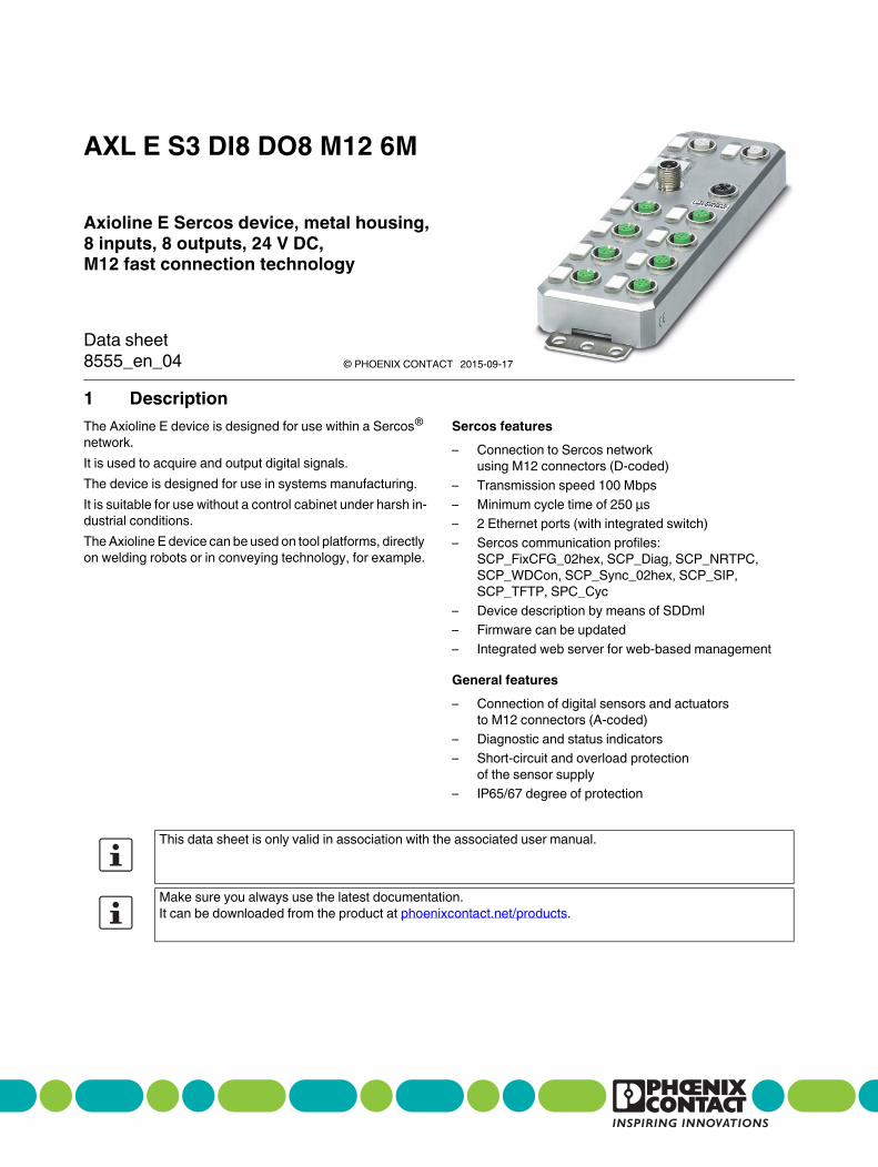
1 Description
Axioline E Sercos device, metal housing,
8 inputs, 8 outputs, 24 V DC,
M12 fast connection technology
AXL E S3 DI8 DO8 M12 6M
© PHOENIX CONTACT
Data sheet
The Axioline E device is designed for use within a Sercos®
network.
It is used to acquire and output digital signals.
The device is designed for use in systems manufacturing.
It is suitable for use without a control cabinet under harsh in-
dustrial conditions.
The Axioline E device can be used on tool platforms, directly
on welding robots or in conveying technology, for example.
Sercos features
– Connection to Sercos network
using M12 connectors (D-coded)
– Transmission speed 100 Mbps
– Minimum cycle time of 250 µs
– 2 Ethernet ports (with integrated switch)
– Sercos communication profiles:
SCP_FixCFG_02hex, SCP_Diag, SCP_NRTPC,
SCP_WDCon, SCP_Sync_02hex, SCP_SIP,
SCP_TFTP, SPC_Cyc
– Device description by means of SDDml
– Firmware can be updated
– Integrated web server for web-based management
General features
– Connection of digital sensors and actuators
to M12 connectors (A-coded)
– Diagnostic and status indicators
– Short-circuit and overload protection
of the sensor supply
– IP65/67 degree of protection
This data sheet is only valid in association with the associated user manual.
Make sure you always use the latest documentation.
It can be downloaded from the product at phoenixcontact.net/products.
8555_en_04 2015-09-17
AXL E S3 DI8 DO8 M12 6M
8555_en_04 PHOENIX CONTACT 2
2 Table of contents
1 Description .............................................................................................................................. 1
2 Table of contents ..................................................................................................................... 2
3 Ordering data .......................................................................................................................... 3
4 Technical data ......................................................................................................................... 4
5 Internal circuit diagram ............................................................................................................ 7
6 Pin assignment ........................................................................................................................ 8
7 Connection example.............................................................................................................. 10
8 Connection notes .................................................................................................................. 10
9 Configuration via rotary encoding switch ............................................................................... 11
10 Local status and diagnostic indicators ................................................................................... 12
11 Sercos realtime connections ................................................................................................. 15
12 Sercos profiles, classes and function groups......................................................................... 15
13 Sercos parameter .................................................................................................................. 16
14 Password (IDN S-0-00267).................................................................................................... 19
15 IP address assignment .......................................................................................................... 19
16 Monitoring connection (connection setup, IDN S-0-1050.x.1) ............................................... 19
17 Electronic rating plate (IDNs S-0-1300.x.y)............................................................................ 19
18 Substitute value behavior ...................................................................................................... 20
19 Diagnostics: I/O and channel errors....................................................................................... 21
20 Mapping the I/Os to Sercos ................................................................................................... 21
21 Delivery state/default settings................................................................................................ 23
22 Restoring the default settings ................................................................................................ 23
23 Firmware started.................................................................................................................... 23
24 Firmware update.................................................................................................................... 23
25 WBM - Web-based management .......................................................................................... 23
26 Device description file (SDDml) ............................................................................................. 23
AXL E S3 DI8 DO8 M12 6M
8555_en_04 PHOENIX CONTACT 3
Description Type Order No. Pcs. / Pkt.
Axioline E Sercos device in metal housing with 8 digital inputs and 8 digital
outputs, 24 V DC, M12 fast connection technology
AXL E S3 DI8 DO8 M12 6M 2701548 1
Accessories Type Order No. Pcs. / Pkt.
An M12 screw plug for the unoccupied M12 sockets of the sensor/actuator
cable, boxes and flush-type connectors (Protection and sealing elements)
PROT-M12 1680539 5
Mounting plate for Axioline E metal devices (Assembly) AXL E MP 60 2701761 1
Snap-in markers, Sheet, white, unlabeled, can be labeled with:
THERMOMARK CARD, BLUEMARK CLED, BLUEMARK LED,
TOPMARK LASER, Mounting type: snapped into marker carrier,
Lettering field: 7 x 10 mm (Marking)
UCT-EM (7X10) 0830765 10
Documentation Type Order No. Pcs. / Pkt.
User manual, English, Axioline E: system and installation UM EN AXL E SYS INST - -
Application note, English:
Updating the firmware of AXL E devices using the Windows Explorer
AH EN FIRMWARE UPDATE AXL E - -
Quick start guide, English:
Startup of Axioline E Sercos devices with IndraWorks
UM QS EN AXL E S3 INDRAWORKS - -
Additional ordering data
For additional accessories, visit phoenixcontact.net/products.
3 Ordering data
AXL E S3 DI8 DO8 M12 6M
8555_en_04 PHOENIX CONTACT 4
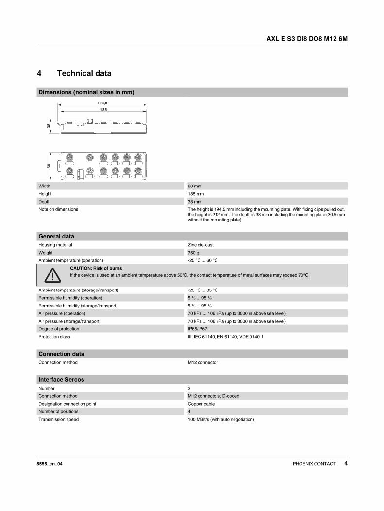
Dimensions (nominal sizes in mm)
Width 60 mm
Height 185 mm
Depth 38 mm
Note on dimensions The height is 194.5 mm including the mounting plate. With fixing clips pulled out,
the height is 212 mm. The depth is 38 mm including the mounting plate (30.5 mm
without the mounting plate).
General data
Housing material Zinc die-cast
Weight 750 g
Ambient temperature (operation) -25 °C ... 60 °C
CAUTION: Risk of burns
If the device is used at an ambient temperature above 50°C, the contact temperature of metal surfaces may exceed 70°C.
Ambient temperature (storage/transport) -25 °C ... 85 °C
Permissible humidity (operation) 5 % ... 95 %
Permissible humidity (storage/transport) 5 % ... 95 %
Air pressure (operation) 70 kPa ... 106 kPa (up to 3000 m above sea level)
Air pressure (storage/transport) 70 kPa ... 106 kPa (up to 3000 m above sea level)
Degree of protection IP65/IP67
Protection class III, IEC 61140, EN 61140, VDE 0140-1
Connection data
Connection method M12 connector
Interface Sercos
Number 2
Connection method M12 connectors, D-coded
Designation connection point Copper cable
Number of positions 4
Transmission speed 100 MBit/s (with auto negotiation)
4 Technical data
194,5
185
38
60
AXL E S3 DI8 DO8 M12 6M
8555_en_04 PHOENIX CONTACT 5
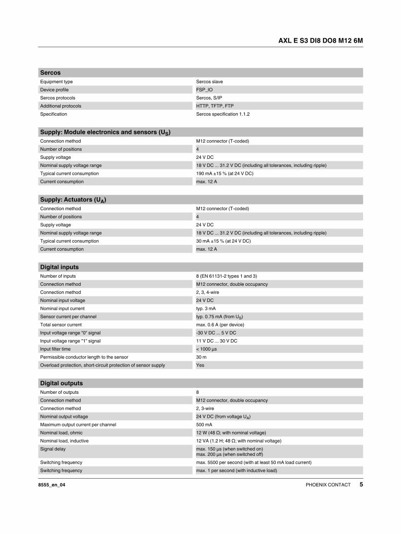
Sercos
Equipment type Sercos slave
Device profile FSP_IO
Sercos protocols Sercos, S/IP
Additional protocols HTTP, TFTP, FTP
Specification Sercos specification 1.1.2
Supply: Module electronics and sensors (US)
Connection method M12 connector (T-coded)
Number of positions 4
Supply voltage 24 V DC
Nominal supply voltage range 18 V DC ... 31.2 V DC (including all tolerances, including ripple)
Typical current consumption 190 mA ±15 % (at 24 V DC)
Current consumption max. 12 A
Supply: Actuators (UA)
Connection method M12 connector (T-coded)
Number of positions 4
Supply voltage 24 V DC
Nominal supply voltage range 18 V DC ... 31.2 V DC (including all tolerances, including ripple)
Typical current consumption 30 mA ±15 % (at 24 V DC)
Current consumption max. 12 A
Digital inputs
Number of inputs 8 (EN 61131-2 types 1 and 3)
Connection method M12 connector, double occupancy
Connection method 2, 3, 4-wire
Nominal input voltage 24 V DC
Nominal input current typ. 3 mA
Sensor current per channel typ. 0.75 mA (from US)
Total sensor current max. 0.6 A (per device)
Input voltage range "0" signal -30 V DC ... 5 V DC
Input voltage range "1" signal 11 V DC ... 30 V DC
Input filter time < 1000 µs
Permissible conductor length to the sensor 30 m
Overload protection, short-circuit protection of sensor supply Yes
Digital outputs
Number of outputs 8
Connection method M12 connector, double occupancy
Connection method 2, 3-wire
Nominal output voltage 24 V DC (from voltage UA)
Maximum output current per channel 500 mA
Nominal load, ohmic 12 W (48 Ω; with nominal voltage)
Nominal load, inductive 12 VA (1.2 H; 48 Ω; with nominal voltage)
Signal delay max. 150 µs (when switched on)
max. 200 µs (when switched off)
Switching frequency max. 5500 per second (with at least 50 mA load current)
Switching frequency max. 1 per second (with inductive load)
AXL E S3 DI8 DO8 M12 6M
8555_en_04 PHOENIX CONTACT 6
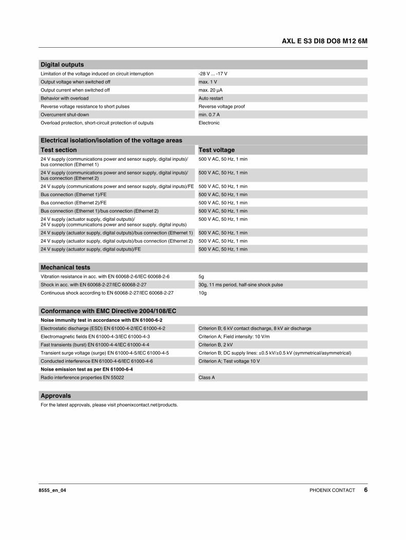
Limitation of the voltage induced on circuit interruption -28 V ... -17 V
Output voltage when switched off max. 1 V
Output current when switched off max. 20 µA
Behavior with overload Auto restart
Reverse voltage resistance to short pulses Reverse voltage proof
Overcurrent shut-down min. 0.7 A
Overload protection, short-circuit protection of outputs Electronic
Electrical isolation/isolation of the voltage areas
Test section Test voltage
24 V supply (communications power and sensor supply, digital inputs)/
bus connection (Ethernet 1)
500 V AC, 50 Hz, 1 min
24 V supply (communications power and sensor supply, digital inputs)/
bus connection (Ethernet 2)
500 V AC, 50 Hz, 1 min
24 V supply (communications power and sensor supply, digital inputs)/FE 500 V AC, 50 Hz, 1 min
Bus connection (Ethernet 1)/FE 500 V AC, 50 Hz, 1 min
Bus connection (Ethernet 2)/FE 500 V AC, 50 Hz, 1 min
Bus connection (Ethernet 1)/bus connection (Ethernet 2) 500 V AC, 50 Hz, 1 min
24 V supply (actuator supply, digital outputs)/
24 V supply (communications power and sensor supply, digital inputs)
500 V AC, 50 Hz, 1 min
24 V supply (actuator supply, digital outputs)/bus connection (Ethernet 1) 500 V AC, 50 Hz, 1 min
24 V supply (actuator supply, digital outputs)/bus connection (Ethernet 2) 500 V AC, 50 Hz, 1 min
24 V supply (actuator supply, digital outputs)/FE 500 V AC, 50 Hz, 1 min
Mechanical tests
Vibration resistance in acc. with EN 60068-2-6/IEC 60068-2-6 5g
Shock in acc. with EN 60068-2-27/IEC 60068-2-27 30g, 11 ms period, half-sine shock pulse
Continuous shock according to EN 60068-2-27/IEC 60068-2-27 10g
Conformance with EMC Directive 2004/108/EC
Noise immunity test in accordance with EN 61000-6-2
Electrostatic discharge (ESD) EN 61000-4-2/IEC 61000-4-2 Criterion B; 6 kV contact discharge, 8 kV air discharge
Electromagnetic fields EN 61000-4-3/IEC 61000-4-3 Criterion A; Field intensity: 10 V/m
Fast transients (burst) EN 61000-4-4/IEC 61000-4-4 Criterion B, 2 kV
Transient surge voltage (surge) EN 61000-4-5/IEC 61000-4-5 Criterion B; DC supply lines: ±0.5 kV/±0.5 kV (symmetrical/asymmetrical)
Conducted interference EN 61000-4-6/IEC 61000-4-6 Criterion A; Test voltage 10 V
Noise emission test as per EN 61000-6-4
Radio interference properties EN 55022 Class A
Approvals
For the latest approvals, please visit phoenixcontact.net/products.
Digital outputs
AXL E S3 DI8 DO8 M12 6M
8555_en_04 PHOENIX CONTACT 7
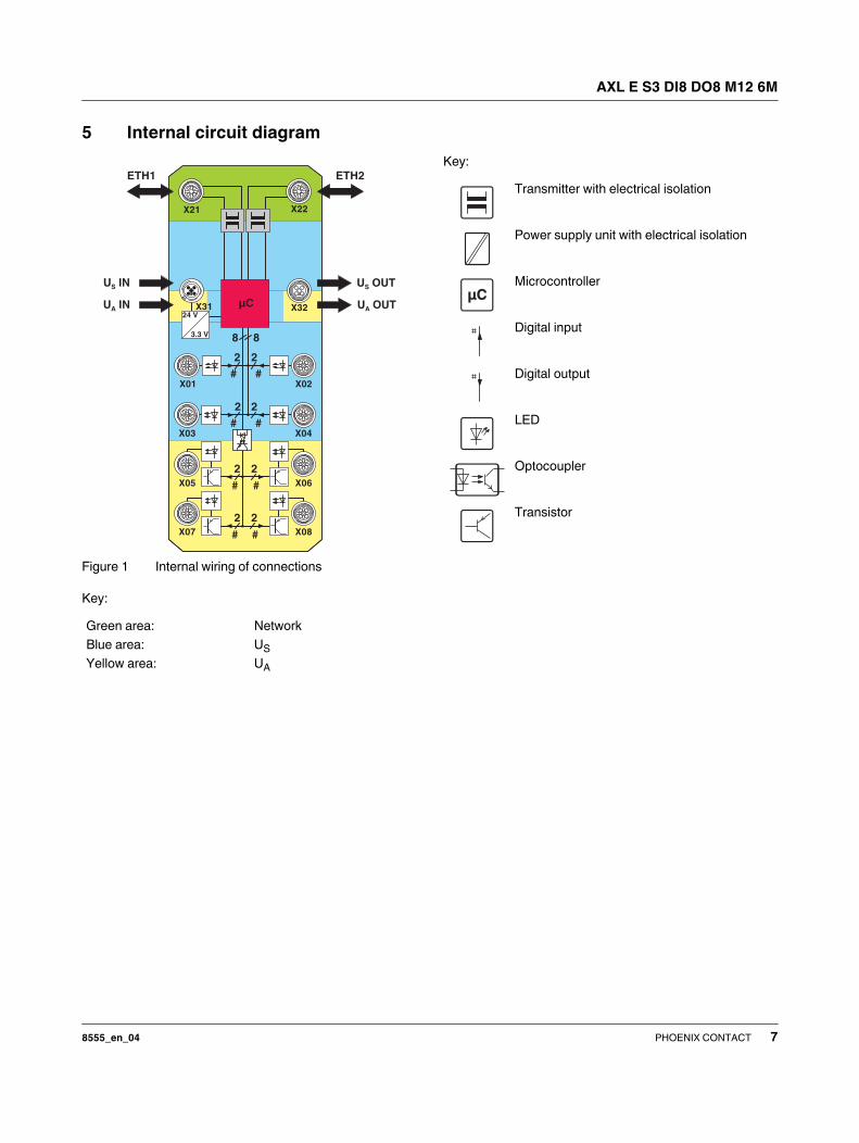
5 Internal circuit diagram
Figure 1 Internal wiring of connections
Key:
Key:
Green area: Network
Blue area: US
Yellow area: UA
X21 X22
X31 X32
X01 X02
X03 X04
X05 X06
X07 X08
2
# #
##
2 2
2
2 2
2
# #
##
2
8 8
24 V
3.3 V
µC
U OUTS
U OUTA
U INS
U INA
ETH1 ETH2
Transmitter with electrical isolation
Power supply unit with electrical isolation
Microcontroller
Digital input
Digital output
LED
Optocoupler
Transistor
µC
AXL E S3 DI8 DO8 M12 6M
8555_en_04 PHOENIX CONTACT 8
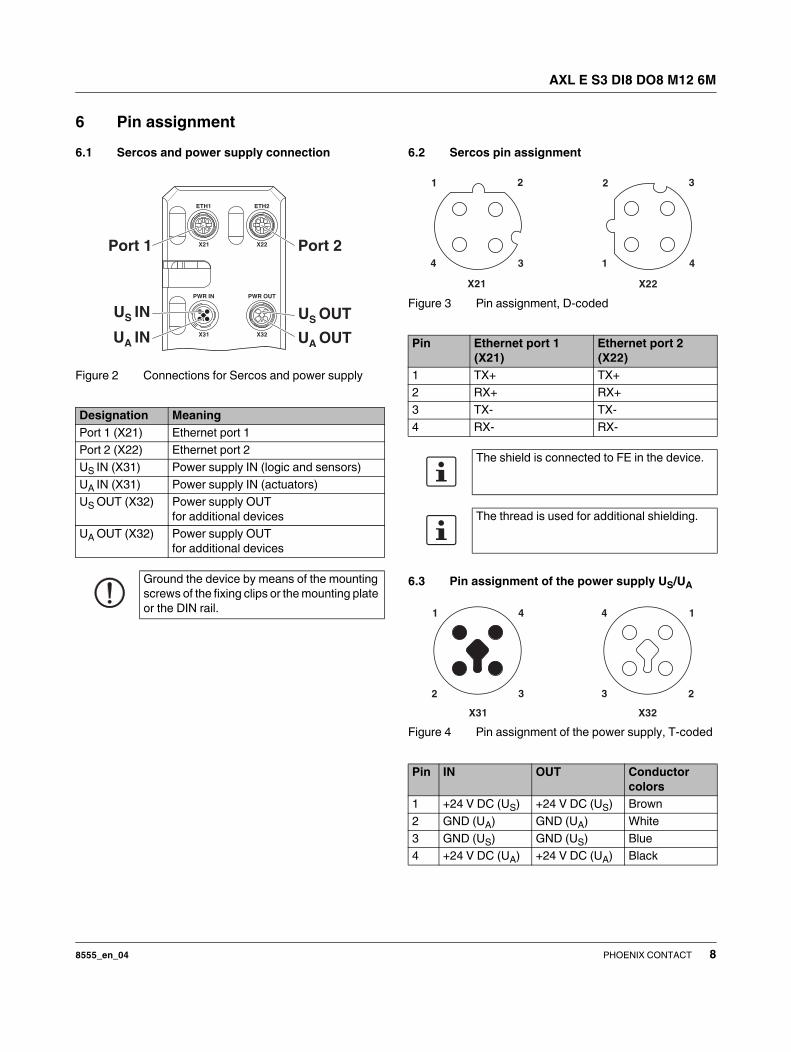
6 Pin assignment
6.1 Sercos and power supply connection
Figure 2 Connections for Sercos and power supply
6.2 Sercos pin assignment
Figure 3 Pin assignment, D-coded
6.3 Pin assignment of the power supply US/UA
Figure 4 Pin assignment of the power supply, T-coded
Designation Meaning
Port 1 (X21) Ethernet port 1
Port 2 (X22) Ethernet port 2
US IN (X31) Power supply IN (logic and sensors)
UA IN (X31) Power supply IN (actuators)
US OUT (X32) Power supply OUT
for additional devices
UA OUT (X32) Power supply OUT
for additional devices
Ground the device by means of the mounting
screws of the fixing clips or the mounting plate
or the DIN rail.
Port 1 Port 2
Pin Ethernet port 1
(X21)
Ethernet port 2
(X22)
1 TX+ TX+
2 RX+ RX+
3 TX- TX-
4 RX- RX-
The shield is connected to FE in the device.
The thread is used for additional shielding.
Pin IN OUT Conductor
colors
1 +24 V DC (US) +24 V DC (US) Brown
2 GND (UA) GND (UA) White
3 GND (US) GND (US) Blue
4 +24 V DC (UA) +24 V DC (UA) Black
1 2
34
X21
2 3
41
X22
X32X31
4
32
1 4
3 2
1
AXL E S3 DI8 DO8 M12 6M
8555_en_04 PHOENIX CONTACT 9
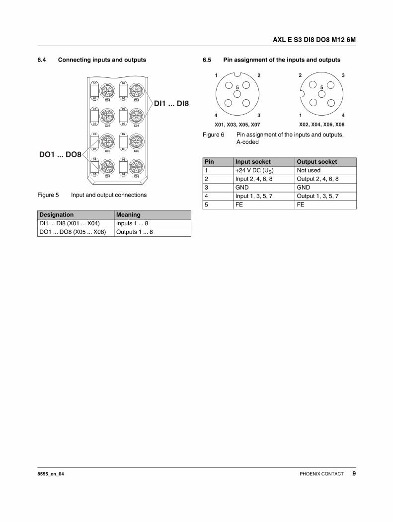
6.4 Connecting inputs and outputs
Figure 5 Input and output connections
6.5 Pin assignment of the inputs and outputs
Figure 6 Pin assignment of the inputs and outputs,
A-coded
Designation Meaning
DI1 ... DI8 (X01 ... X04) Inputs 1 ... 8
DO1 ... DO8 (X05 ... X08) Outputs 1 ... 8
Pin Input socket Output socket
1 +24 V DC (US) Not used
2 Input 2, 4, 6, 8 Output 2, 4, 6, 8
3 GND GND
4 Input 1, 3, 5, 7 Output 1, 3, 5, 7
5 FE FE
X01, X03, X05, X07
2
34
5
1
X02, X04, X06, X08
2 3
4
5
1
AXL E S3 DI8 DO8 M12 6M
8555_en_04 PHOENIX CONTACT 10
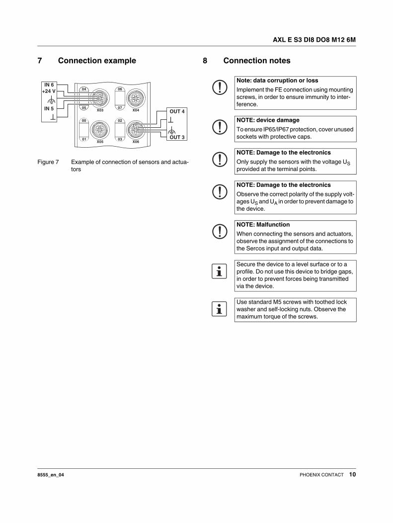
7 Connection example
Figure 7 Example of connection of sensors and actua-
tors
8 Connection notes
IN 6
+24 V
IN 5
OUT 3
OUT 4
Note: data corruption or loss
Implement the FE connection using mounting
screws, in order to ensure immunity to inter-
ference.
NOTE: device damage
To ensure IP65/IP67 protection, cover unused
sockets with protective caps.
NOTE: Damage to the electronics
Only supply the sensors with the voltage US
provided at the terminal points.
NOTE: Damage to the electronics
Observe the correct polarity of the supply volt-
ages US and UA in order to prevent damage to
the device.
NOTE: Malfunction
When connecting the sensors and actuators,
observe the assignment of the connections to
the Sercos input and output data.
Secure the device to a level surface or to a
profile. Do not use this device to bridge gaps,
in order to prevent forces being transmitted
via the device.
Use standard M5 screws with toothed lock
washer and self-locking nuts. Observe the
maximum torque of the screws.
AXL E S3 DI8 DO8 M12 6M
8555_en_04 PHOENIX CONTACT 11
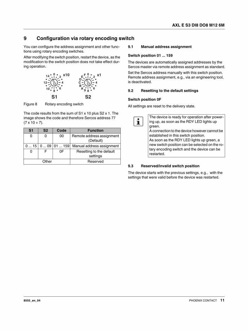
9 Configuration via rotary encoding switch
You can configure the address assignment and other func-
tions using rotary encoding switches.
After modifying the switch position, restart the device, as the
modification to the switch position does not take effect dur-
ing operation.
Figure 8 Rotary encoding switch
The code results from the sum of S1 x 10 plus S2 x 1. The
image shows the code and therefore Sercos address 77
(7 x 10 + 7).
9.1 Manual address assignment
Switch position 01 ... 159
The devices are automatically assigned addresses by the
Sercos master via remote address assignment as standard.
Set the Sercos address manually with this switch position.
Remote address assignment, e.g., via an engineering tool,
is deactivated.
9.2 Resetting to the default settings
Switch position 0F
All settings are reset to the delivery state.
9.3 Reserved/invalid switch position
The device starts with the previous settings, e.g., with the
settings that were valid before the device was restarted.
S1 S2 Code Function
0 0 00 Remote address assignment
(Default)
0 ... 15 0 ... 09 01 ... 159 Manual address assignment
0 F 0F Resetting to the default
settings
Other Reserved
02
4
689
ABCD
EF
S2
x102
4
68
10
12
14
S1
x10
The device is ready for operation after power-
ing up, as soon as the RDY LED lights up
green.
A connection to the device however cannot be
established in this switch position.
As soon as the RDY LED lights up green, a
new switch position can be selected on the ro-
tary encoding switch and the device can be
restarted.
AXL E S3 DI8 DO8 M12 6M
8555_en_04 PHOENIX CONTACT 12
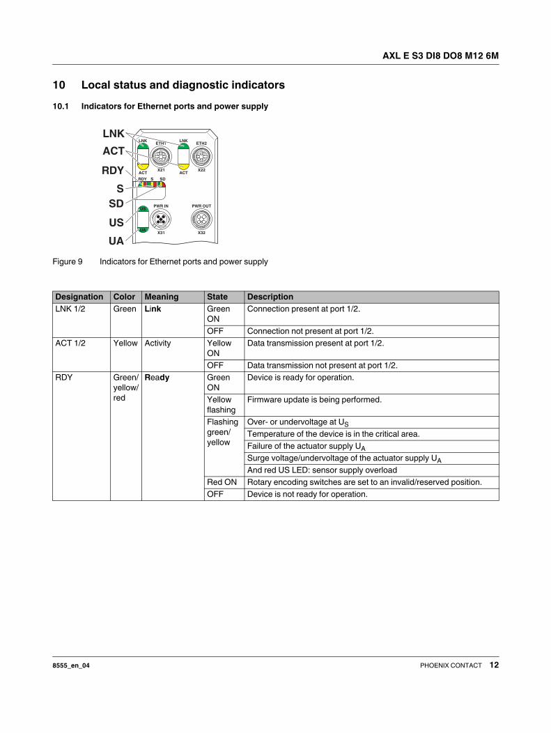
10 Local status and diagnostic indicators
10.1 Indicators for Ethernet ports and power supply
Figure 9 Indicators for Ethernet ports and power supply
Designation Color Meaning State Description
LNK 1/2 Green Link Green
ON
Connection present at port 1/2.
OFF Connection not present at port 1/2.
ACT 1/2 Yellow Activity Yellow
ON
Data transmission present at port 1/2.
OFF Data transmission not present at port 1/2.
RDY Green/
yellow/
red
Ready Green
ON
Device is ready for operation.
Yellow
flashing
Firmware update is being performed.
Flashing
green/
yellow
Over- or undervoltage at US
Temperature of the device is in the critical area.
Failure of the actuator supply UA
Surge voltage/undervoltage of the actuator supply UA
And red US LED: sensor supply overload
Red ON Rotary encoding switches are set to an invalid/reserved position.
OFF Device is not ready for operation.
AXL E S3 DI8 DO8 M12 6M
8555_en_04 PHOENIX CONTACT 13
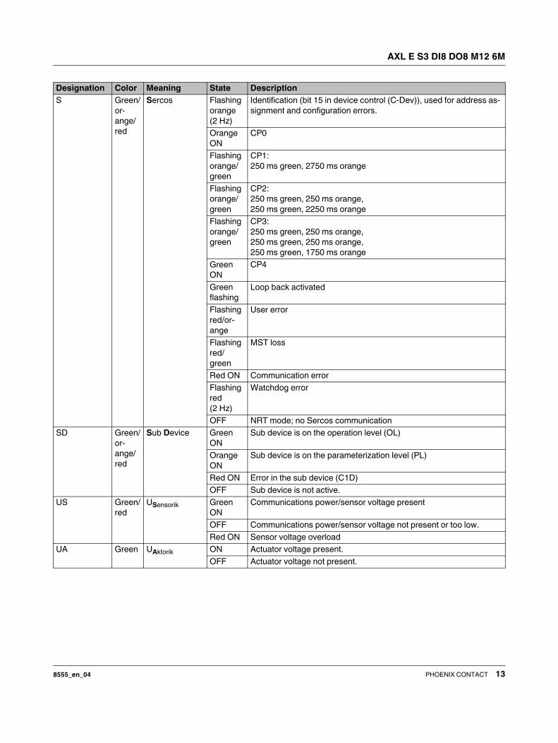
S Green/
or-
ange/
red
Sercos Flashing
orange
(2 Hz)
Identification (bit 15 in device control (C-Dev)), used for address as-
signment and configuration errors.
Orange
ON
CP0
Flashing
orange/
green
CP1:
250 ms green, 2750 ms orange
Flashing
orange/
green
CP2:
250 ms green, 250 ms orange,
250 ms green, 2250 ms orange
Flashing
orange/
green
CP3:
250 ms green, 250 ms orange,
250 ms green, 250 ms orange,
250 ms green, 1750 ms orange
Green
ON
CP4
Green
flashing
Loop back activated
Flashing
red/or-
ange
User error
Flashing
red/
green
MST loss
Red ON Communication error
Flashing
red
(2 Hz)
Watchdog error
OFF NRT mode; no Sercos communication
SD Green/
or-
ange/
red
Sub Device Green
ON
Sub device is on the operation level (OL)
Orange
ON
Sub device is on the parameterization level (PL)
Red ON Error in the sub device (C1D)
OFF Sub device is not active.
US Green/
red
USensorik Green
ON
Communications power/sensor voltage present
OFF Communications power/sensor voltage not present or too low.
Red ON Sensor voltage overload
UA Green UAktorik ON Actuator voltage present.
OFF Actuator voltage not present.
Designation Color Meaning State Description
AXL E S3 DI8 DO8 M12 6M
8555_en_04 PHOENIX CONTACT 14
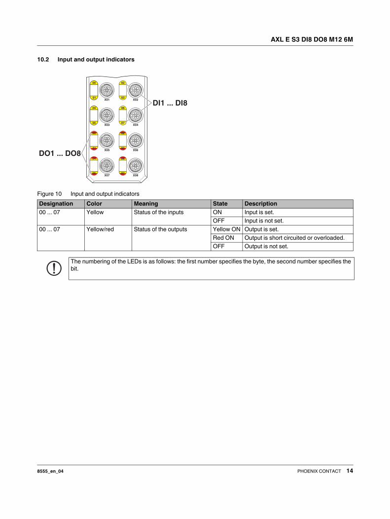
10.2 Input and output indicators
Figure 10 Input and output indicators
Designation Color Meaning State Description
00 ... 07 Yellow Status of the inputs ON Input is set.
OFF Input is not set.
00 ... 07 Yellow/red Status of the outputs Yellow ON Output is set.
Red ON Output is short circuited or overloaded.
OFF Output is not set.
The numbering of the LEDs is as follows: the first number specifies the byte, the second number specifies the
bit.
AXL E S3 DI8 DO8 M12 6M
8555_en_04 PHOENIX CONTACT 15
11 Sercos realtime connections
The device supports a maximum of two realtime data con-
nections (S-0-1050.0.x and S-1050.1.x), with a maximum of
one consumer and one producer connection.
12 Sercos profiles, classes and func-
tion groups
The following Sercos profiles, classes, and function groups
are implemented in the device.
12.1 Sercos device profile
(GDP: Generic device profile)
– Basic device profile (GDP_Basic)
– Diagnostics (FG_Diagnosis)
– Administration (FG_Administration)
– Device identification (FG_Identification)
– Revisions (GDP_Rev)
– Password (GDP_PWD)
– Diagnostic records (GDP_DiagT)
– Extended diagnostic records (GDP_DiagTAdv)
– Restart (GDP_RST)
12.2 Sercos communication model
(SCP: Sercos communication profiles)
– Fixed configuration (SCP_FixCFG_02hex)
– Diagnostics (SCP_Diag)
– Non-realtime channel (SCP_NRTPC)
– Consumer connection monitoring (SCP_WDCon)
– Synchronous and isochronous producer and consumer
data (SCP_Sync_02hex)
– Support for SCP_SIP and SCP_TFTP, TFTP is only ac-
tive if it was activated via WBM.
– Cyclic data exchange (SCP_Cyc)
12.3 Sercos function model
(FSP: Function specific profile IO)
– I/O function model (FSP_IO)
AXL E S3 DI8 DO8 M12 6M
8555_en_04 PHOENIX CONTACT 16
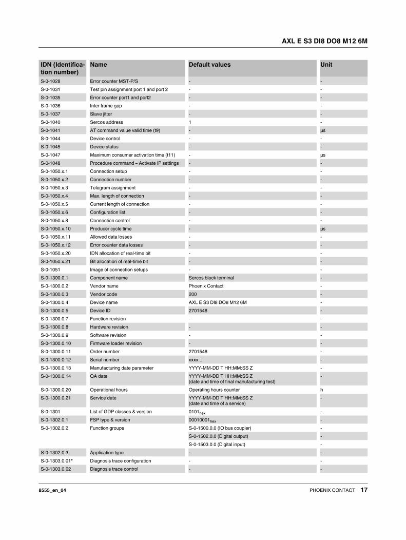
13 Sercos parameter
The following table lists all Sercos parameters (S and P parameters) with important features that have been implemented in
the device.
IDN (Identifica-
tion number)
Name Default values Unit
S-0-0014 Interface status - -
S-0-0015.0.0 Telegram type - -
S-0-0017 IDN list of all operation data - -
S-0-0021 IDN list of invalid operation data for CP2 - -
S-0-0022 IDN list of invalid operation data for CP3 - -
S-0-0025 IDN list of all procedure commands - -
S-0-0095 Diagnostic message - -
S-0-0099 Reset class 1 diagnostic (process command) - -
S-0-0127 CP3 transition check (process command) - -
S-0-0128 CP4 transition check (process command) - -
S-0-0267 Password PW170875 -
S-0-0279 IDN-list of password protected data - -
S-0-0390 Diagnostic number - -
S-0-398 IDN list of configurable data as producer - -
S-0-399 IDN list of configurable data as consumer - -
S-0-1000 SCP type & version - -
S-0-1002 Communication cycle time (tScyc) - μs
S-0-1003 Allowed MST losses in CP3/CP4 10 -
S-0-1005 Minimum feedback processing time (t5) - μs
S-0-1006 AT0 transmission starting time (t1) - μs
S-0-1007 Feedback acquisition capture point (t4) - μs
S-0-1008 Command value valid time (t3) - μs
S-0-1009 Device control (C-Dev) offset in MDT - -
S-0-1010 Length of MDTs - -
S-0-1011 Device status (S-Dev) offset in AT - -
S-0-1012 Length of ATs - -
S-0-1013 SVC offset in MDT - -
S-0-1014 SVC offset in AT - -
S-0-1015 Ring delay - μs
S-0-1016 Slave delay - μs
S-0-1017 NRT transmission time - μs
S-0-1019 MAC address 00.A0.45.xx.xx.xx -
S-0-1020 IP address 192.168.0.20 -
S-0-1020.0.1 Current IP address 192.168.0.20 -
S-0-1021 Subnet mask 255.255.255.0 -
S-0-1021.0.1 Current subnet mask 255.255.255.0 -
S-0-1022 Gateway address 192.168.0.1 -
S-0-1022.0.1 Current gateway address 192.168.0.1 -
S-0-1023 SYNC jitter - μs
S-0-1024 SYNC delay measuring procedure command
(process command)
- -
S-0-1026 Version of communication hardware - -
S-0-1027.0.1 Requested MTU - -
S-0-1027.0.2 Effective MTU - -
AXL E S3 DI8 DO8 M12 6M
8555_en_04 PHOENIX CONTACT 17
S-0-1028 Error counter MST-P/S - -
S-0-1031 Test pin assignment port 1 and port 2 - -
S-0-1035 Error counter port1 and port2 - -
S-0-1036 Inter frame gap - -
S-0-1037 Slave jitter - -
S-0-1040 Sercos address 1 -
S-0-1041 AT command value valid time (t9) - μs
S-0-1044 Device control - -
S-0-1045 Device status - -
S-0-1047 Maximum consumer activation time (t11) - μs
S-0-1048 Procedure command – Activate IP settings - -
S-0-1050.x.1 Connection setup - -
S-0-1050.x.2 Connection number - -
S-0-1050.x.3 Telegram assignment - -
S-0-1050.x.4 Max. length of connection - -
S-0-1050.x.5 Current length of connection - -
S-0-1050.x.6 Configuration list - -
S-0-1050.x.8 Connection control - -
S-0-1050.x.10 Producer cycle time - μs
S-0-1050.x.11 Allowed data losses - -
S-0-1050.x.12 Error counter data losses - -
S-0-1050.x.20 IDN allocation of real-time bit - -
S-0-1050.x.21 Bit allocation of real-time bit - -
S-0-1051 Image of connection setups - -
S-0-1300.0.1 Component name Sercos block terminal -
S-0-1300.0.2 Vendor name Phoenix Contact -
S-0-1300.0.3 Vendor code 200 -
S-0-1300.0.4 Device name AXL E S3 DI8 DO8 M12 6M -
S-0-1300.0.5 Device ID 2701548 -
S-0-1300.0.7 Function revision - -
S-0-1300.0.8 Hardware revision - -
S-0-1300.0.9 Software revision - -
S-0-1300.0.10 Firmware loader revision - -
S-0-1300.0.11 Order number 2701548 -
S-0-1300.0.12 Serial number xxxx... -
S-0-1300.0.13 Manufacturing date parameter YYYY-MM-DD T HH:MM:SS Z -
S-0-1300.0.14 QA date YYYY-MM-DD T HH:MM:SS Z
(date and time of final manufacturing test)
-
S-0-1300.0.20 Operational hours Operating hours counter h
S-0-1300.0.21 Service date YYYY-MM-DD T HH:MM:SS Z
(date and time of a service)
-
S-0-1301 List of GDP classes & version 0101hex -
S-0-1302.0.1 FSP type & version 00010001hex -
S-0-1302.0.2 Function groups S-0-1500.0.0 (IO bus coupler) -
S-0-1502.0.0 (Digital output) -
S-0-1503.0.0 (Digital input) -
S-0-1302.0.3 Application type - -
S-0-1303.0.01* Diagnosis trace configuration - -
S-0-1303.0.02 Diagnosis trace control - -
IDN (Identifica-
tion number)
Name Default values Unit
AXL E S3 DI8 DO8 M12 6M
8555_en_04 PHOENIX CONTACT 18
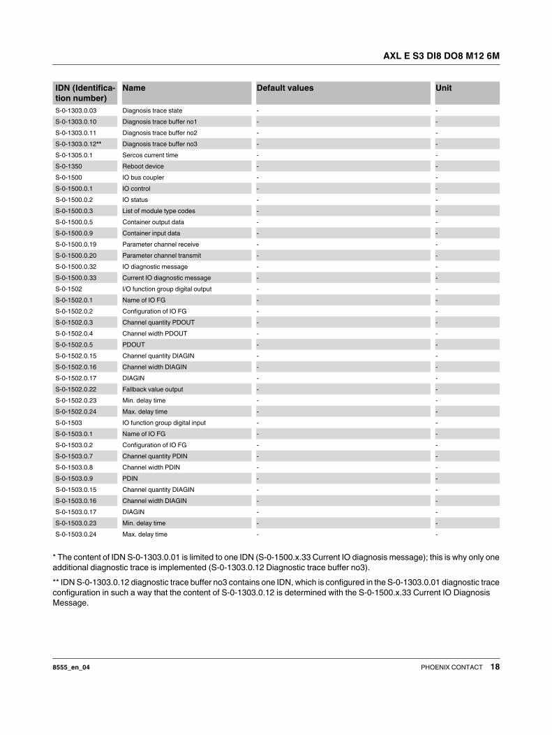
* The content of IDN S-0-1303.0.01 is limited to one IDN (S-0-1500.x.33 Current IO diagnosis message); this is why only one
additional diagnostic trace is implemented (S-0-1303.0.12 Diagnostic trace buffer no3).
** IDN S-0-1303.0.12 diagnostic trace buffer no3 contains one IDN, which is configured in the S-0-1303.0.01 diagnostic trace
configuration in such a way that the content of S-0-1303.0.12 is determined with the S-0-1500.x.33 Current IO Diagnosis
Message.
S-0-1303.0.03 Diagnosis trace state - -
S-0-1303.0.10 Diagnosis trace buffer no1 - -
S-0-1303.0.11 Diagnosis trace buffer no2 - -
S-0-1303.0.12** Diagnosis trace buffer no3 - -
S-0-1305.0.1 Sercos current time - -
S-0-1350 Reboot device - -
S-0-1500 IO bus coupler - -
S-0-1500.0.1 IO control - -
S-0-1500.0.2 IO status - -
S-0-1500.0.3 List of module type codes - -
S-0-1500.0.5 Container output data - -
S-0-1500.0.9 Container input data - -
S-0-1500.0.19 Parameter channel receive - -
S-0-1500.0.20 Parameter channel transmit - -
S-0-1500.0.32 IO diagnostic message - -
S-0-1500.0.33 Current IO diagnostic message - -
S-0-1502 I/O function group digital output - -
S-0-1502.0.1 Name of IO FG - -
S-0-1502.0.2 Configuration of IO FG - -
S-0-1502.0.3 Channel quantity PDOUT - -
S-0-1502.0.4 Channel width PDOUT - -
S-0-1502.0.5 PDOUT - -
S-0-1502.0.15 Channel quantity DIAGIN - -
S-0-1502.0.16 Channel width DIAGIN - -
S-0-1502.0.17 DIAGIN - -
S-0-1502.0.22 Fallback value output - -
S-0-1502.0.23 Min. delay time - -
S-0-1502.0.24 Max. delay time - -
S-0-1503 IO function group digital input - -
S-0-1503.0.1 Name of IO FG - -
S-0-1503.0.2 Configuration of IO FG - -
S-0-1503.0.7 Channel quantity PDIN - -
S-0-1503.0.8 Channel width PDIN - -
S-0-1503.0.9 PDIN - -
S-0-1503.0.15 Channel quantity DIAGIN - -
S-0-1503.0.16 Channel width DIAGIN - -
S-0-1503.0.17 DIAGIN - -
S-0-1503.0.23 Min. delay time - -
S-0-1503.0.24 Max. delay time - -
IDN (Identifica-
tion number)
Name Default values Unit
AXL E S3 DI8 DO8 M12 6M
8555_en_04 PHOENIX CONTACT 19
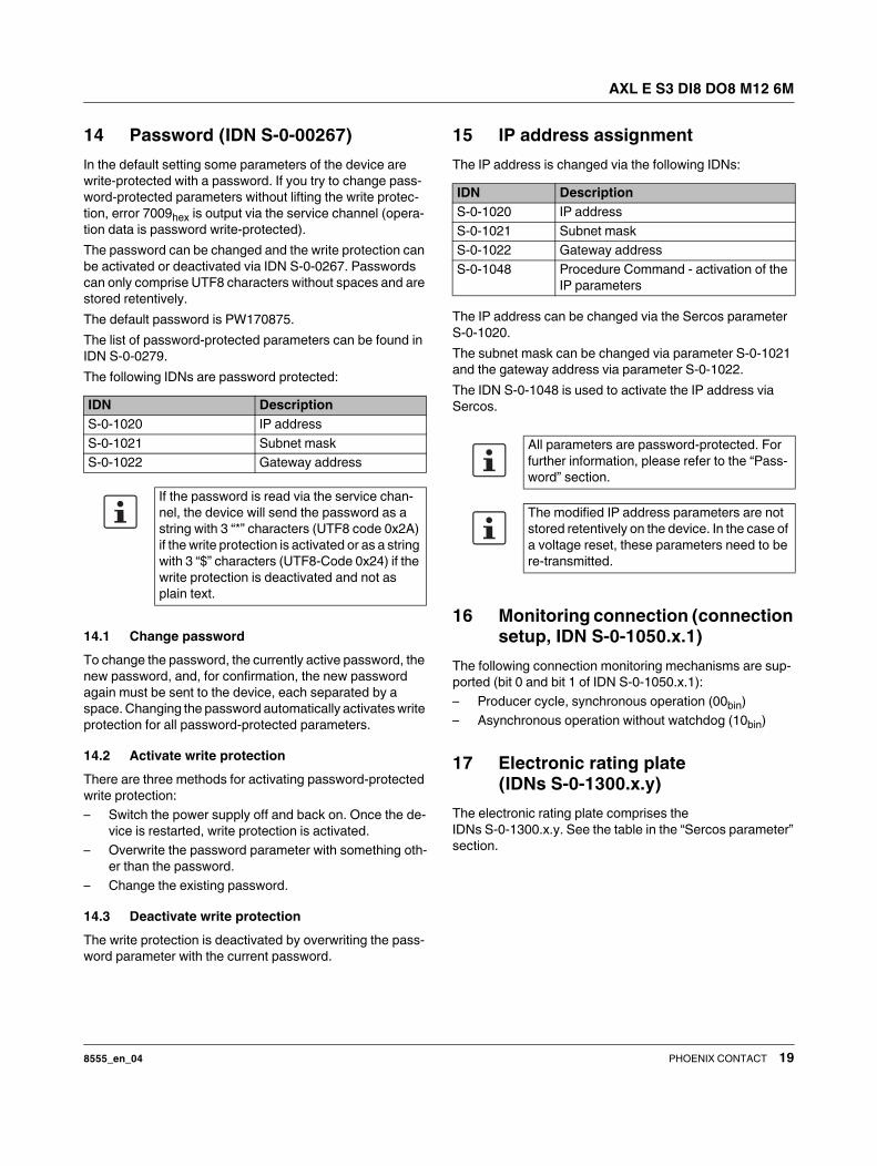
14 Password (IDN S-0-00267)
In the default setting some parameters of the device are
write-protected with a password. If you try to change pass-
word-protected parameters without lifting the write protec-
tion, error 7009hex is output via the service channel (opera-
tion data is password write-protected).
The password can be changed and the write protection can
be activated or deactivated via IDN S-0-0267. Passwords
can only comprise UTF8 characters without spaces and are
stored retentively.
The default password is PW170875.
The list of password-protected parameters can be found in
IDN S-0-0279.
The following IDNs are password protected:
14.1 Change password
To change the password, the currently active password, the
new password, and, for confirmation, the new password
again must be sent to the device, each separated by a
space. Changing the password automatically activates write
protection for all password-protected parameters.
14.2 Activate write protection
There are three methods for activating password-protected
write protection:
– Switch the power supply off and back on. Once the de-
vice is restarted, write protection is activated.
– Overwrite the password parameter with something oth-
er than the password.
– Change the existing password.
14.3 Deactivate write protection
The write protection is deactivated by overwriting the pass-
word parameter with the current password.
15 IP address assignment
The IP address is changed via the following IDNs:
The IP address can be changed via the Sercos parameter
S-0-1020.
The subnet mask can be changed via parameter S-0-1021
and the gateway address via parameter S-0-1022.
The IDN S-0-1048 is used to activate the IP address via
Sercos.
16 Monitoring connection (connection
setup, IDN S-0-1050.x.1)
The following connection monitoring mechanisms are sup-
ported (bit 0 and bit 1 of IDN S-0-1050.x.1):
– Producer cycle, synchronous operation (00bin)
– Asynchronous operation without watchdog (10bin)
17 Electronic rating plate
(IDNs S-0-1300.x.y)
The electronic rating plate comprises the
IDNs S-0-1300.x.y. See the table in the “Sercos parameter”
section.
IDN Description
S-0-1020 IP address
S-0-1021 Subnet mask
S-0-1022 Gateway address
If the password is read via the service chan-
nel, the device will send the password as a
string with 3 “*” characters (UTF8 code 0x2A)
if the write protection is activated or as a string
with 3 “$” characters (UTF8-Code 0x24) if the
write protection is deactivated and not as
plain text.
IDN Description
S-0-1020 IP address
S-0-1021 Subnet mask
S-0-1022 Gateway address
S-0-1048 Procedure Command - activation of the
IP parameters
All parameters are password-protected. For
further information, please refer to the “Pass-
word” section.
The modified IP address parameters are not
stored retentively on the device. In the case of
a voltage reset, these parameters need to be
re-transmitted.
AXL E S3 DI8 DO8 M12 6M
8555_en_04 PHOENIX CONTACT 20
18 Substitute value behavior
The Axioline E Sercos devices support the substitute value behavior for outputs. If Sercos communication fails, all device out-
puts are set to the parameterized substitute values. The configuration and behavior of the substitute values can be defined
via parameters S-0-1502.0.02 and S-0-1502.0.22.
The following substitute values are supported:
Substitute
value
Description Configuration
Reset all All outputs are set to “0”. S-0-1502.0.02 “Configuration of IO FG” bit 6 = 0 (fallback)
and S-0-1502.0.22 “Fallback value output” with the value “0”
parameterized for all process data bits.
Set all All outputs are set to “1”. S-0-1502.0.02 “Configuration of IO FG” bit 6 = 0 (fallback)
and S-0-1502.0.22 “Fallback value output” parameterized
with the value “1” for all process data bits.
Hold last value All outputs keep the last value. If S-0-1502.0.02 “Configuration of IO FG” bit 6 = 1 (freeze) is
parameterized.
Switch replace-
ment value
All outputs are set to an application-spe-
cific, parameterized value.
S-0-1502.0.02 “Configuration of IO FG” bit 6 = 0 (fallback)
and S-0-1502.0.22 “Fallback value output” are parameter-
ized with the application-specific value for all process data
bits.

AXL E S3 DI8 DO8 M12 6M
8555_en_04 PHOENIX CONTACT 21
19 Diagnostics: I/O and channel errors
Sercos enables the Sercos device to store diagnostic infor-
mation together with the error location and error type.
Diagnostic messages are enabled by default, but can be dis-
abled via a parameter on startup.
The Sercos master is informed that diagnostic information
that has been entered.
If at least one item of diagnostic information has been
stored, this is indicated by the S and SD LEDs.
The following Sercos diagnostic messages are indicated by
the Sercos slave:
– Overtemperature of the device
– Surge voltage of US
– Overload of US
– Surge voltage of UA
– Undervoltage of UA
– Short-circuit or overload of an output
I/O and channel errors are mapped in the following diagnos-
tic IDNs according to Sercos specifications.
20 Mapping the I/Os to Sercos
The device has just one Sercos module and therefore only
has one structure instance 0.
The I/Os are assigned to the structure instances and
IO function groups according to the Sercos IO profile.
The following function groups are defined:
The cyclical data of the Sercos device is mapped to the
IDNs S-0-1502 and S-0-1503 according to FSP_IO.
The device supports the following IDNs as configurable
data:
IDN Description
S-0-0095 Diagnostic message
S-0-0390 Diagnostic number
S-1500.0.32 IO diagnostic message
S-1500.0.33 Current IO diagnostic message
S-1303.0.10 Diagnostic trace buffer no 1
S-1303.0.11 Diagnostic trace buffer no 2
S-1303.0.12 Diagnostic trace buffer no 3
Function group
(FG_IO)
Name
S-0-1502 IO function group digital output
S-0-1503 IO function group digital input
In a producer connection In a consumer connection
S-0-1500.0.2 S-0-1500.0.1
S-0-1500.0.9 S-0-1500.0.1
FG_IO.x.9 FG_IO.x.5
FG_IO.x.13 FG_IO.x.11
S-0-0390 S-0-0390
This information is stored in:
S-0-0187 S-0-0188
AXL E S3 DI8 DO8 M12 6M
8555_en_04 PHOENIX CONTACT 22
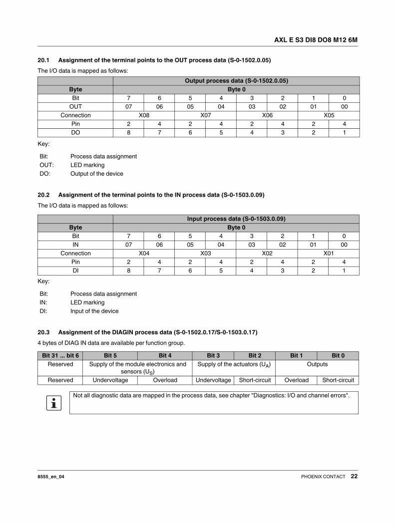
20.1 Assignment of the terminal points to the OUT process data (S-0-1502.0.05)
The I/O data is mapped as follows:
Key:
20.2 Assignment of the terminal points to the IN process data (S-0-1503.0.09)
The I/O data is mapped as follows:
Key:
20.3 Assignment of the DIAGIN process data (S-0-1502.0.17/S-0-1503.0.17)
4 bytes of DIAG IN data are available per function group.
Output process data (S-0-1502.0.05)
Byte Byte 0
Bit 7 6 5 4 3 2 1 0
OUT 07 06 05 04 03 02 01 00
Connection X08 X07 X06 X05
Pin 2 4 2 4 2 4 2 4
DO 8 7 6 5 4 3 2 1
Bit: Process data assignment
OUT: LED marking
DO: Output of the device
Input process data (S-0-1503.0.09)
Byte Byte 0
Bit 7 6 5 4 3 2 1 0
IN 07 06 05 04 03 02 01 00
Connection X04 X03 X02 X01
Pin 2 4 2 4 2 4 2 4
DI 8 7 6 5 4 3 2 1
Bit: Process data assignment
IN: LED marking
DI: Input of the device
Bit 31 ... bit 6 Bit 5 Bit 4 Bit 3 Bit 2 Bit 1 Bit 0
Reserved Supply of the module electronics and
sensors (US)
Supply of the actuators (UA) Outputs
Reserved Undervoltage Overload Undervoltage Short-circuit Overload Short-circuit
Not all diagnostic data are mapped in the process data, see chapter "Diagnostics: I/O and channel errors".
AXL E S3 DI8 DO8 M12 6M
8555_en_04 23PHOENIX CONTACT GmbH & Co. KG • 32823 Blomberg • Germany
phoenixcontact.com
21 Delivery state/default settings
By default upon delivery, the following functions and fea-
tures are available:
IP settings
Firmware update
Web-based Management (WBM)
22 Restoring the default settings
The following options are available for restoring the default
settings:
Rotary encoding switch
Switch position 0F, for further information see section “Con-
figuration via rotary coding switch”.
Web-based Management (WBM)
Navigate to “Manage > Default settings” and follow the in-
structions.
23 Firmware started
Once you have connected the power, the firmware is
started.
After completion of the firmware boot process, the RDY LED
lights up green.
24 Firmware update
In order to update the firmware of the device, the device
must be provided with a firmware container via a TFTP
server or it must be loaded onto the device via FTP. Any FTP
client or TFTP server can be used for this. The update must
always be initiated by the web-based management. When
carrying out the firmware update, the RDY LED flashes yel-
low.
25 WBM - Web-based management
The device has a web server, which generates the required
pages for web-based management and, depending on the
requirements of the user, sends them to a standard web
browser. Web-based management can be used to access
static information (e.g., technical data, MAC address) or dy-
namic information (e.g., IP address, status information).
Calling web-based management
The device web server can be addressed using the IP ad-
dress if configured accordingly. The homepage (web page)
of the device is accessed by entering the URL “http://ip-ad-
dress”.
Example: http://192.168.0.20
The default user name is “admin”, the default password is
“private”.
26 Device description file (SDDml)
A configuration file (SDDml) is provided for parameterization
in an engineering system.
Parameterization can then be carried out by the Sercos
master.
If several versions of the configuration file are available,
make sure that you are working with the file version that cor-
responds to the firmware/hardware version used.
Sercos address: 1
IP address: 192.168.0.20
Subnet mask: 255.255.255.0
Gateway address 192.168.0.1
Firmware update on next re-
start:
deactivated
TFTP server IP address: 192.168.210.211
Firmware file name: FIRMWARE.NXF
User name: admin
Password: private
If you cannot access the WBM pages, check
the connection settings in your browser and
deactivate the proxy, if set.
For the latest device description files, visit
phoenixcontact.net/products.
Recommended


![Configuring VG224 Using AXL SQL Direct Queries [AXL THIN ... · VERSION: 03-01-2008 Configuring VG224 Using AXL SQL Direct Queries [AXL THIN API], Thick API [CM7]](https://img.pdfslide.net/doc/110x75/5e48329b43b7a701dd344f4b/configuring-vg224-using-axl-sql-direct-queries-axl-thin-version-03-01-2008.jpg)