BASIC MECHANICAL ENGINEERING
UNIT 4
MANUFACTURING PROCESSES
PART 1 – FOUNDRY PRACTICE
PART 2 – WELDING
FOUNDRY PRACTICE Foundry practice involves the preparation of solid
patterns, preparation of a cavity with the help of the patterns in a moulding material, pouring a molten metal in the cavity of the mould and withdrawing the solidified metal, called casting, from the mould.
Depending up on the method of mould preparation or the pouring method of the metal the processes are variously designated as Sand moulding, Shell moulding or Die casting etc….
BASIC FEATURES Pattern and Mould
A pattern is made of wood or metal, is a replica of the final product and is used for preparing mould cavity
Mould cavity which contains molten metal is essentially a negative of the final product
Mould material should posses refractory characteristics and with stand the pouring temperature
When the mold is used for single casting, it made of sand and known as expendable mold
When the mold is used repeatedly for number of castings and is made of metal or graphite are called permanent mould
For making holes or hollow cavities inside a casting, cores made of either sand or metal are used.
PATTERNS
Patterns are the copies of castingsTYPES
Single-piece patternSplit patternFollow board patternCope and drag patternMatch plate patternLoose-piece patternSweep patternSkeleton pattern
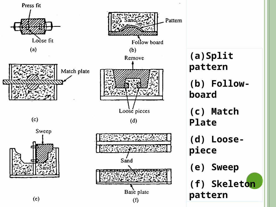
(a)Split pattern
(b) Follow-board
(c) Match Plate
(d) Loose-piece
(e) Sweep
(f) Skeleton pattern
PATTERN MATERIALS Patterns may be constructed from the following materials.
Each material has its own advantages, limitations, and field of application. Some materials used for making patterns are:
wood, metals and alloys, plastic, plaster of Paris, plastic and rubbers, wax, and resins. To be suitable for use, the pattern
material should be: 1. Easily worked, shaped and joined 2. Light in weight 3. Strong, hard and durable 4. Resistant to wear and abrasion 5. Resistant to corrosion, and to chemical reactions 6. Dimensionally stable and unaffected by variations in
temperature and humidity 7. Available at low cost
PATTERN MATERIALS Wood Metals like Cast iron, Steel, Brass, Aluminium, Plastics Plaster of paris or gypsum cement, Wax The selection of pattern materials depends on the
fallowing factors 1. Production quantity2. Dimensional accuracy required 3. Moulding process used 4. Size and shape of the pattern
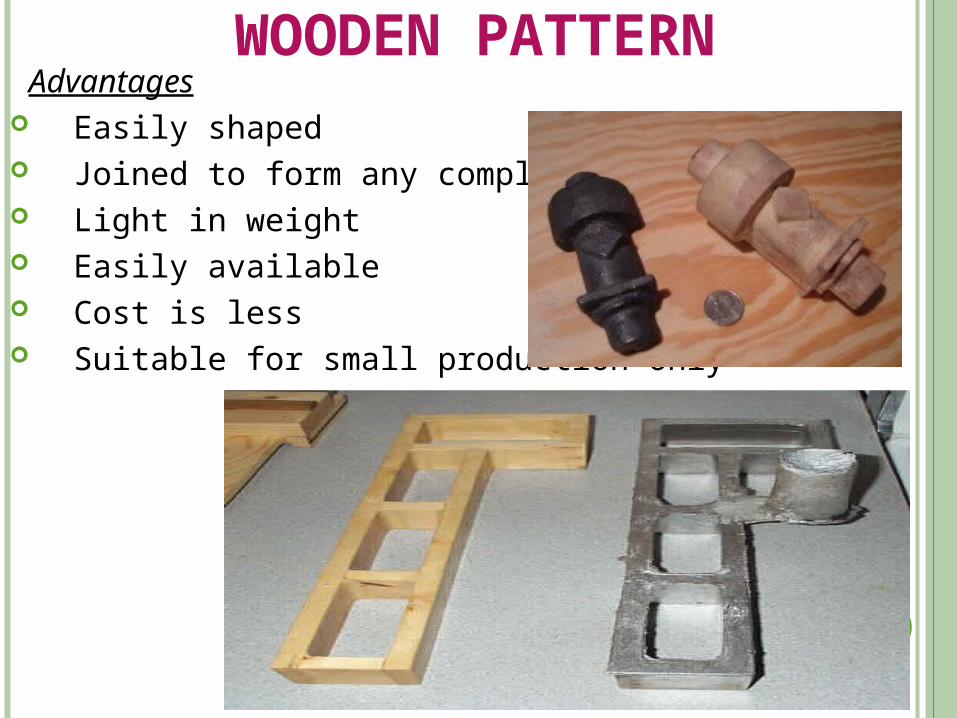
WOODEN PATTERN Advantages Easily shaped Joined to form any complex shape Light in weight Easily available Cost is less Suitable for small production only
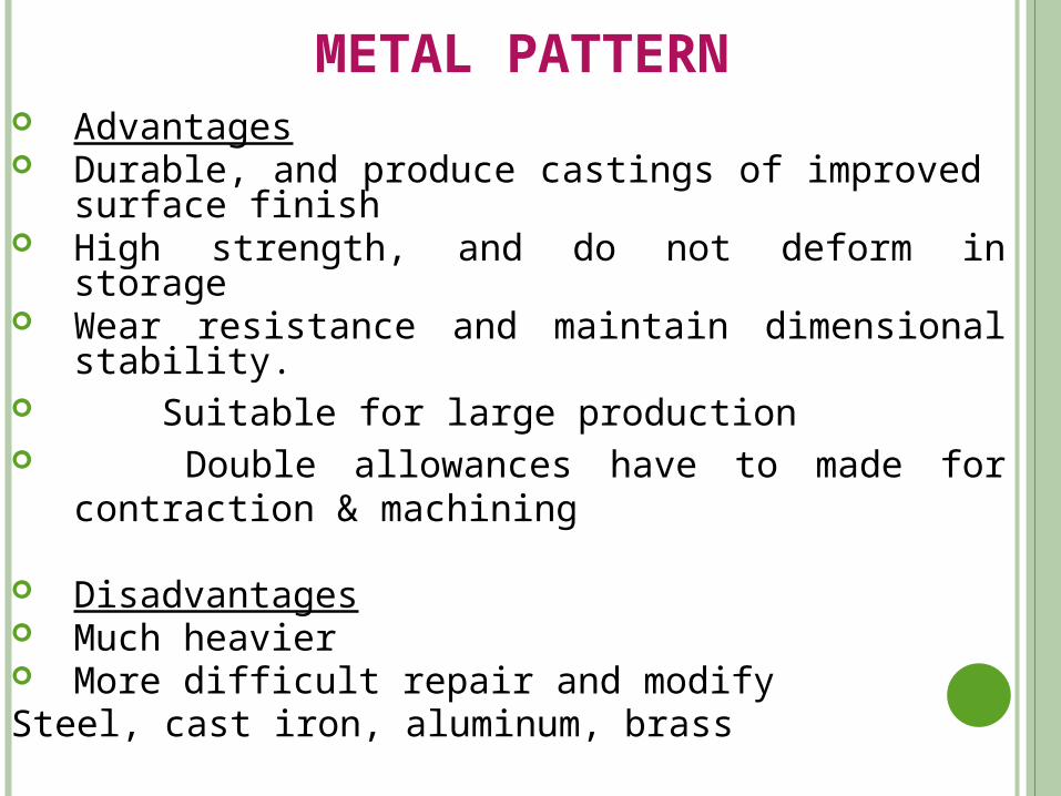
METAL PATTERN Advantages Durable, and produce castings of improved surface
finish High strength, and do not deform in storage Wear resistance and maintain dimensional stability. Suitable for large production Double allowances have to made for contraction &
machining
Disadvantages Much heavier More difficult repair and modify Steel, cast iron, aluminum, brass
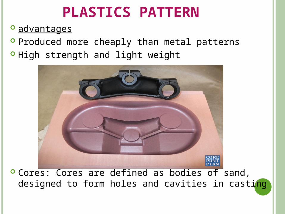
PLASTICS PATTERN advantages Produced more cheaply than metal patterns High strength and light weight
Cores: Cores are defined as bodies of sand, designed to form holes and cavities in casting
PATTERN ALLOWANCES The size of pattern is slightly larger than the finished casting by
an amount is called allowance
A pattern dimensions are more than the casting dimensions
The following allowances are given to the pattern
1. Shrinkage allowance
2. Machining allowances
3. Draft allowances
4. Distortion allowances
5. Rapping allowances
SHRINKAGE ALLOWANCES:
The pattern must be made oversize to compensate for contraction of liquid metal on cooling
This addition to the dimension of the pattern is known as shrinkage allowance.
MACHINING ALLOWANCES: It is often necessary to produce the finished surface of casting by
machining The excess in the dimensions of the casting is called machining
allowances Machining allowances in addition to shrinkage allowance is given
to the pattern
DRAFT ALLOWANCES
When a pattern is removed from a mold ,the tendency to tear away the edges of the mold is greatly reduced the vertical surfaces of the pattern are tapered inwards
The provision of taper on vertical faces of the pattern is called draft
The amount of draft recommended on external surfaces varies from 10 to 20mm per Meter
DISTORTION ALLOWANCES
Distortion allowances are applied to the castings of irregular
shapes
That are distorted in cooling because of metal shrinkage
RAPPING ALLOWANCES: Due to rapping of the pattern in the mold, the size of mold cavity
increases slightly
These increase is insignificant for small and medium size of
casting but it must be considered large castings
MOULDING It is the process of preparing a mould, a cavity in a suitable
material called moulding material, into which the molten metal is poured to produce the casting.
MOULDING METHODS: Sand mouldinga. Bench moulding b. Floor moulding c. Pit moulding andd. Machine moulding Green sand moulding Dry sand moulding Skin-dried moulding Loam moulding Cement bonded moulding Co2 -process moulding Shell moulding
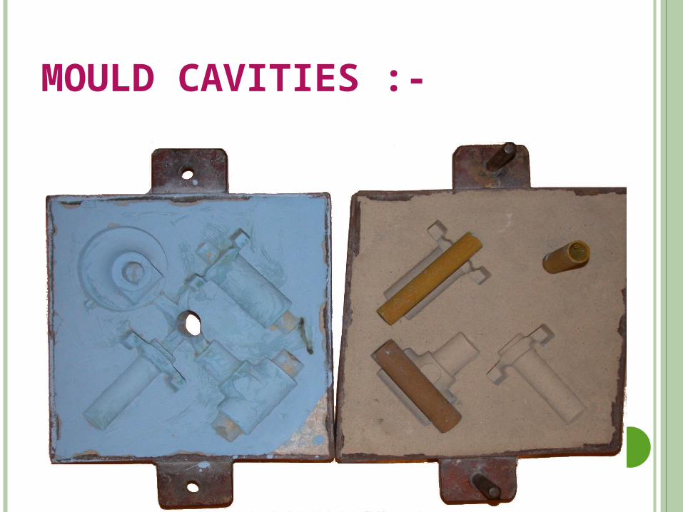
MOULD CAVITIES :-
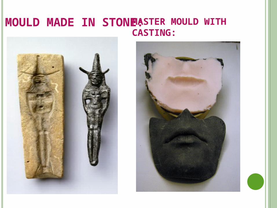
MOULD MADE IN STONE: MASTER MOULD WITH CASTING:
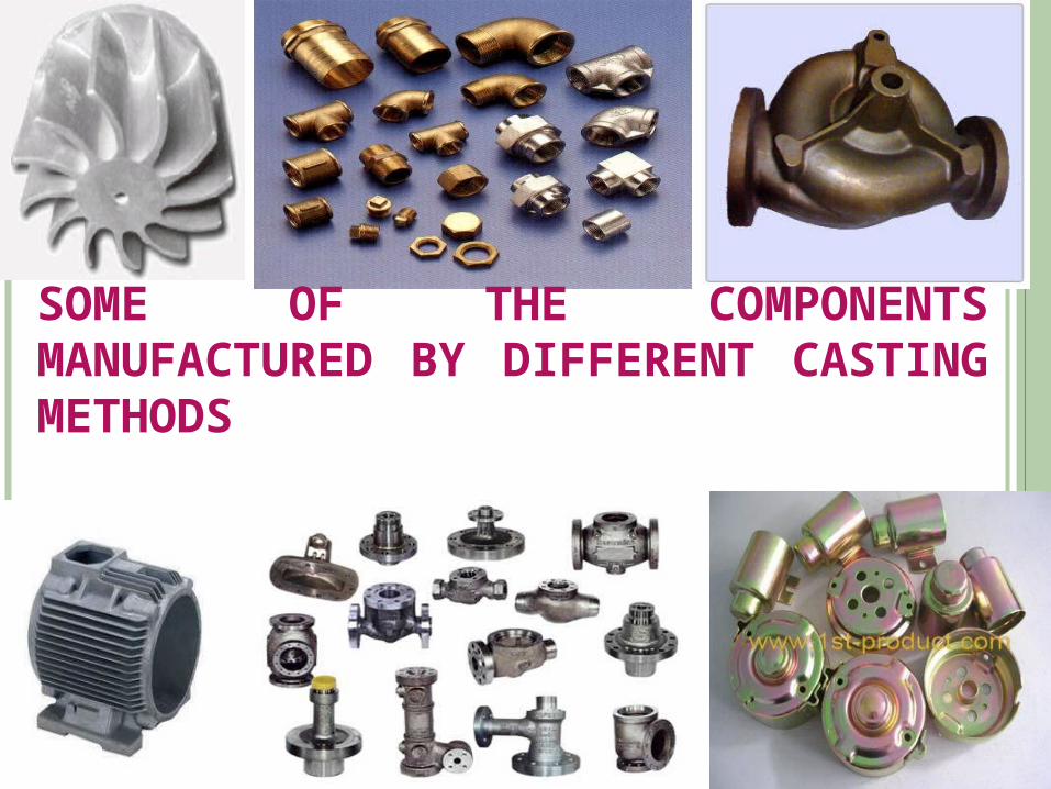
SOME OF THE COMPONENTS MANUFACTURED BY DIFFERENT CASTING METHODS
MOULDING MATERIALS
Types of moulding materials: MOULDING SANDS:
1. Refractory sand grains
2. Clay
3. Water
4. Special additives VARIOUS TYPES OF FOUNDRY SANDS:
1. Natural moulding sand
2. Synthetic sand
3. Parting sand
4. Facing sand
5. Floor sand or backing sand
6. Core sand
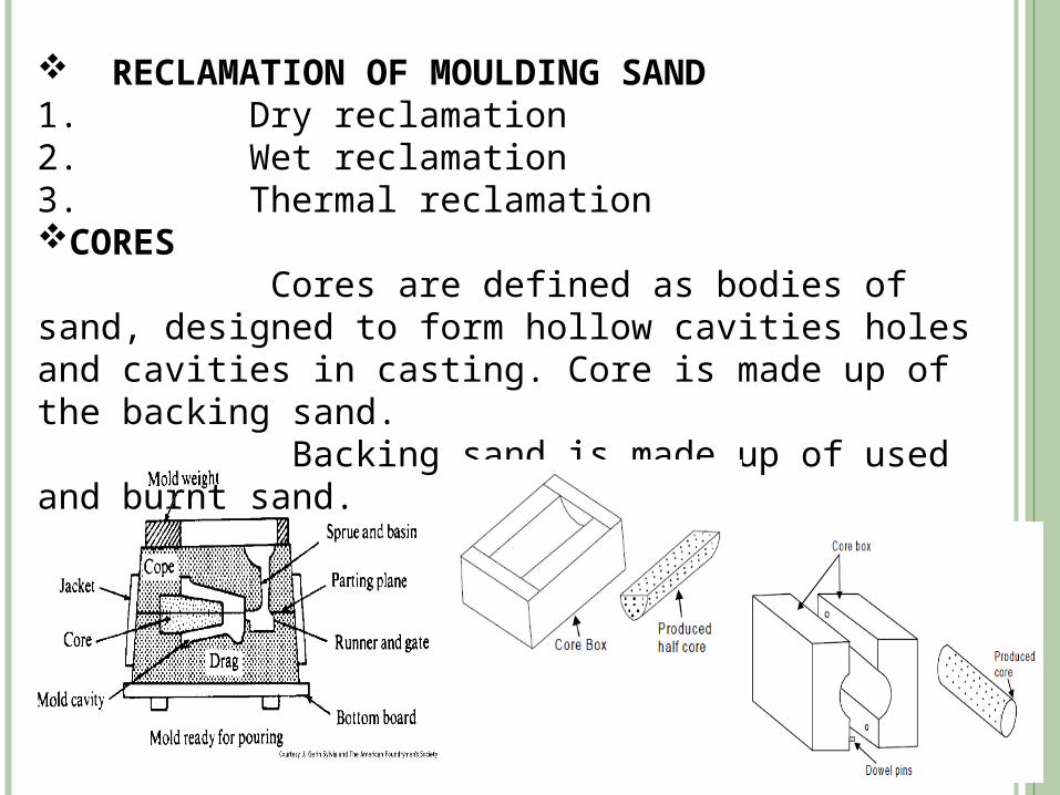
RECLAMATION OF MOULDING SAND1. Dry reclamation2. Wet reclamation3. Thermal reclamationCORES Cores are defined as bodies of sand, designed to form hollow cavities holes and cavities in casting. Core is made up of the backing sand. Backing sand is made up of used and burnt sand.
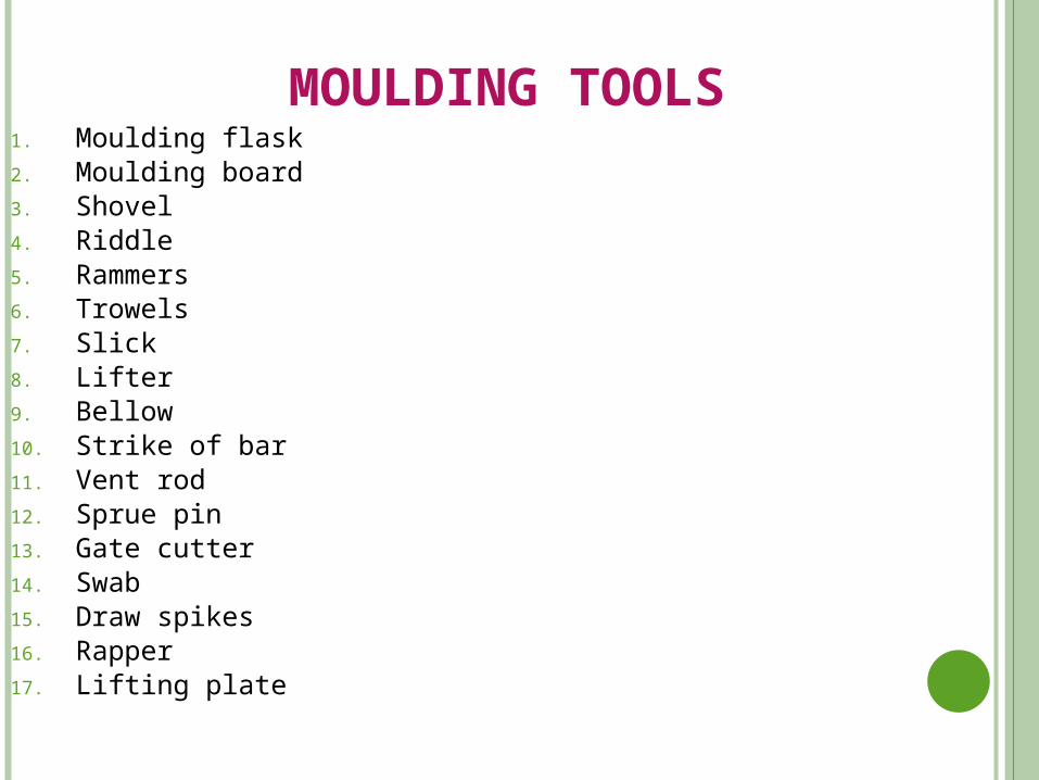
MOULDING TOOLS1. Moulding flask 2. Moulding board 3. Shovel 4. Riddle5. Rammers6. Trowels7. Slick8. Lifter9. Bellow10. Strike of bar11. Vent rod12. Sprue pin 13. Gate cutter14. Swab15. Draw spikes16. Rapper17. Lifting plate
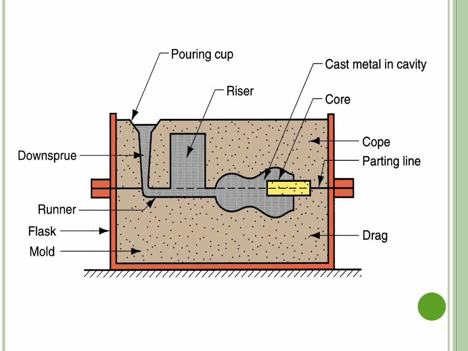
SAND CASTING MOLD
CASTING MOLD TERMS
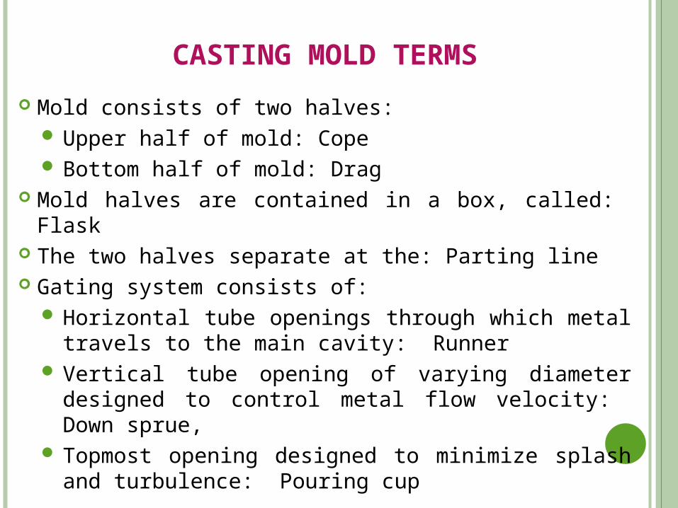
Mold consists of two halves: Upper half of mold: CopeBottom half of mold: Drag
Mold halves are contained in a box, called: Flask The two halves separate at the: Parting line Gating system consists of:
Horizontal tube openings through which metal travels to the main cavity: Runner
Vertical tube opening of varying diameter designed to control metal flow velocity: Down sprue,
Topmost opening designed to minimize splash and turbulence: Pouring cup
RISER
Reservoir in the mold which acts as a source of liquid metal during
solidification to: compensate for shrinkage of the part
In order to satisfy its function, the riser must be designed to
freeze (before or after) the main casting
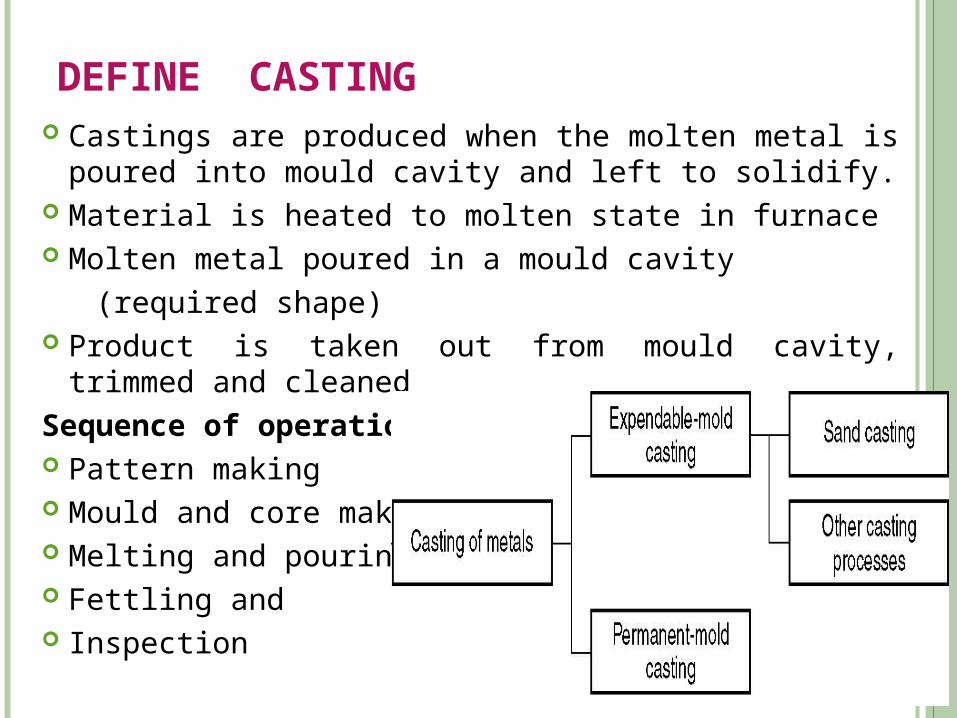
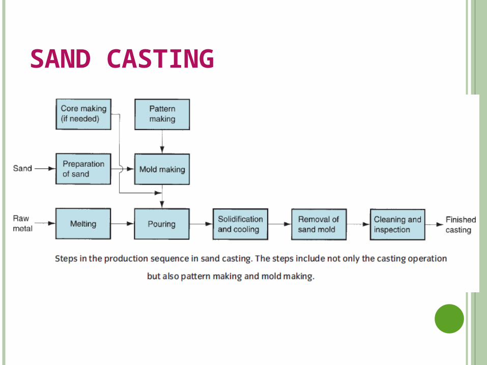
DEFINE CASTING Castings are produced when the molten metal is poured into
mould cavity and left to solidify. Material is heated to molten state in furnace Molten metal poured in a mould cavity
(required shape) Product is taken out from mould cavity, trimmed and cleaned
Sequence of operations Pattern making Mould and core making Melting and pouring Fettling and Inspection
TWO CATEGORIES OF CASTING PROCESSES
1. Uses a mold which is destroyed to remove casting: expendable
mold processes
Mold materials: sand, plaster, and similar materials, plus
binders
2. Uses a mold which can be used over and over: permanent mold
processes
Made of metal (or, less commonly, a ceramic refractory
material
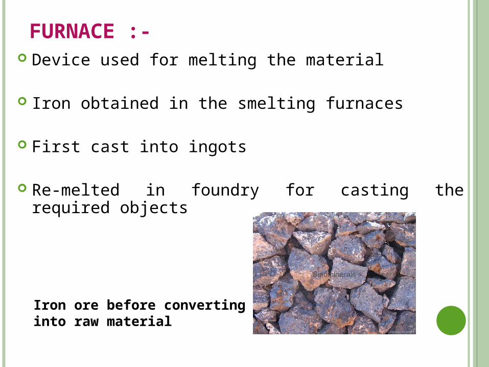
FURNACE :- Device used for melting the material
Iron obtained in the smelting furnaces
First cast into ingots
Re-melted in foundry for casting the required objects
Iron ore before converting into raw material
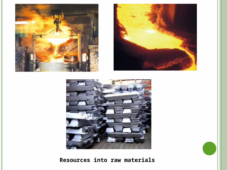
Resources into raw materials
FOR SUCCESSFUL CASTING Preparation of mould
Melting & pouring
Solidification
Defects & inspection
CAPABILITIES OF CASTING
Can create complex part geometries
Can create both external and internal shapes
Some casting processes are net shape; others are near net shape
Can produce a wide variety of sized parts:
Large parts: Engine blocks, wood burning stoves, railway
wheels, pipes, church bells, statues, etc. Small parts: dental crowns, jewelry, small statues, frying
pans
LIMITATIONS OF CASTING
1. Limitations on mechanical properties (cold working, heat
treating, alloy segregation, etc.)
2. Poor dimensional accuracy and surface finish for some
processes; e.g., sand casting
3. Safety hazards to workers due to hot molten metals
APPLICATIONS OF CASTING PROCESS
Typical applications of sand casting are: Cylinder blocks Liners Machine tool beds Pistons Piston rings Mill rolls Wheels Housings Water supply pipes Bells etc…….
ADVANTAGES OF CASTING PROCESS
Possible to cast any material (ferrous or non-ferrous). Tools required (for casting moulds) are simple & inexpensive. Weight reduction in design can be achieved. No directional properties. Casting of any size & weight even up to 200 tons can be made. Molten material flow into any small sections in the cavity & any
intricate shapes can be made. Scrap can be recycled.
CASTING METHODS
Sand mould casting process
Shell-mould casting process
Investment casting process
Die casting (metal mould)
Centrifugal casting
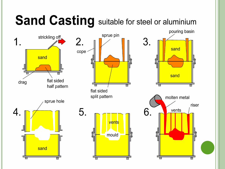
SAND MOULD CASTING :- Widely used process Expendable mould Process involves the use of furnace, raw material, pattern,
moulding sand, cope & drag, tools for making mould
Process cycle for sand casting process :- Mould making Clamping Pouring Cooling Removal Trimming
SAND CASTING
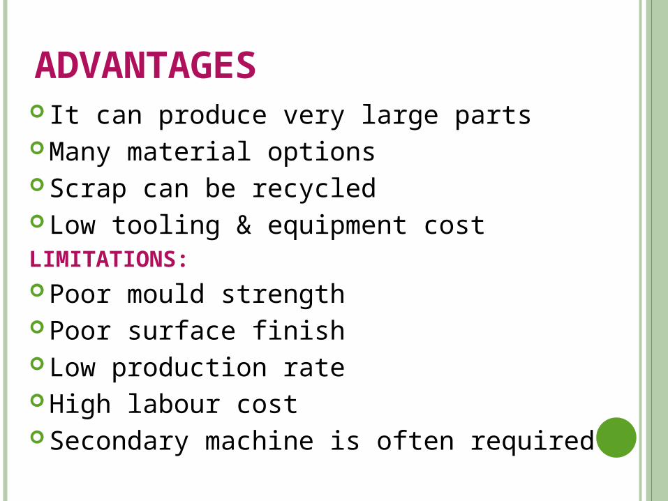
ADVANTAGES It can produce very large parts Many material options Scrap can be recycled Low tooling & equipment costLIMITATIONS: Poor mould strength Poor surface finish Low production rate High labour cost Secondary machine is often required
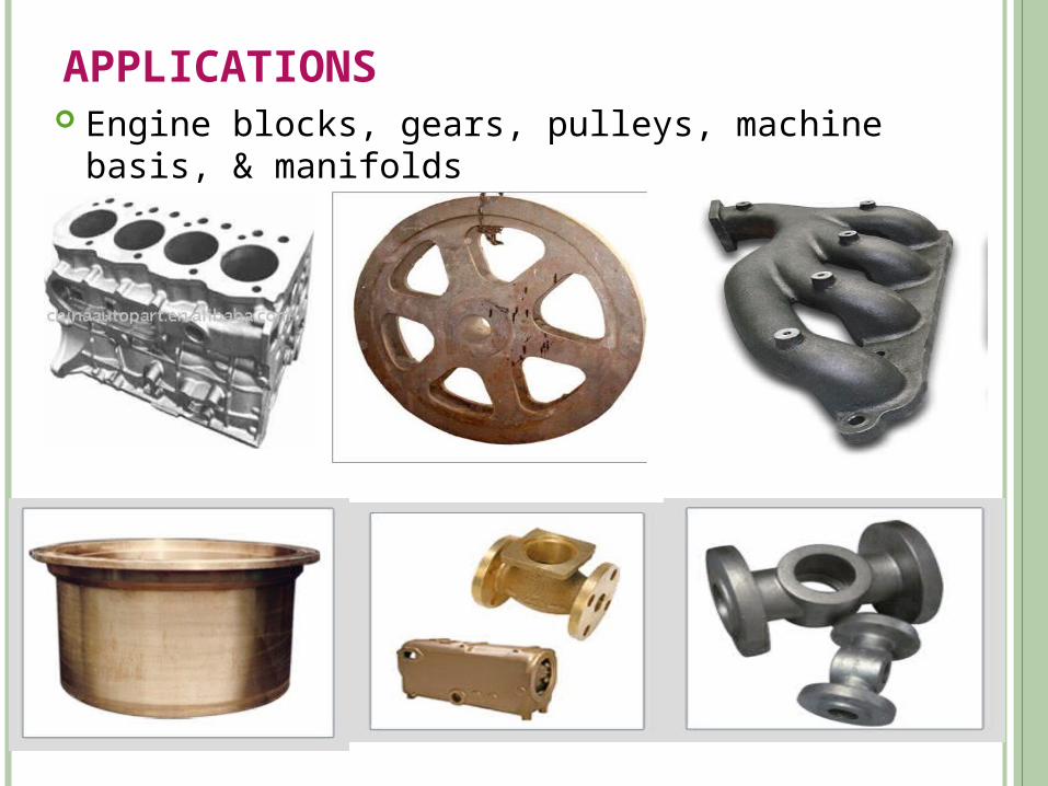
APPLICATIONS Engine blocks, gears, pulleys, machine basis, &
manifolds
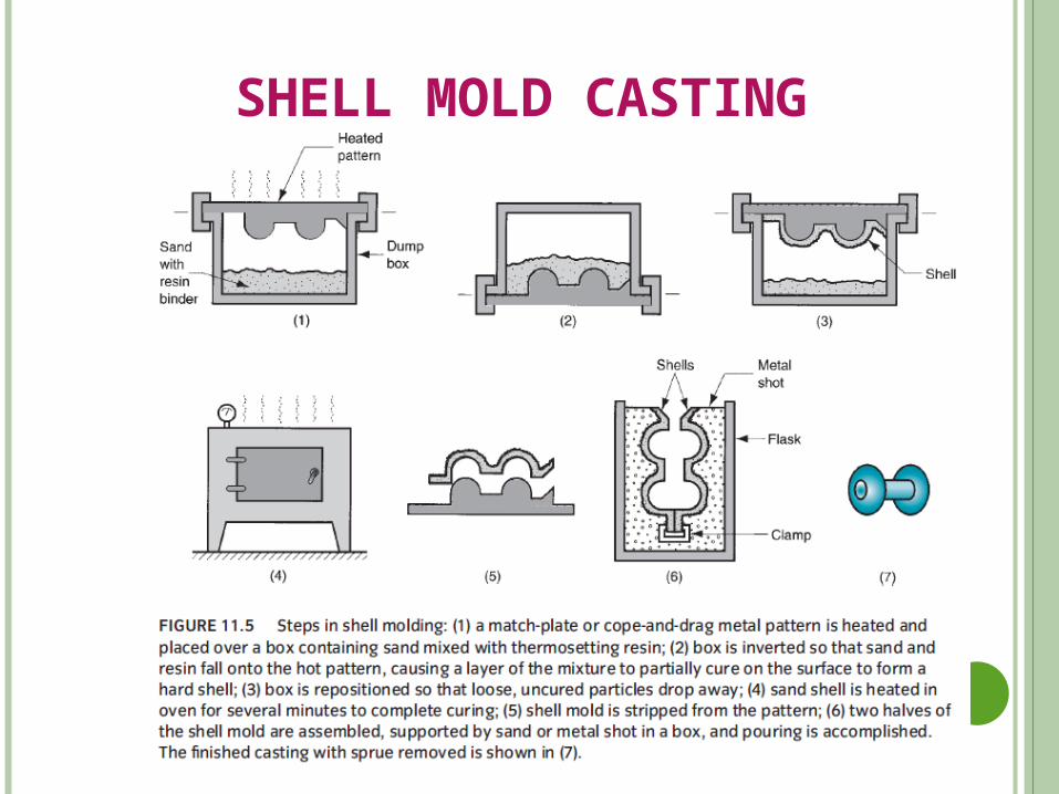
SHELL MOLD CASTING
Shell molding is a casting process in which the mold is a
thin shell (typically 9 mmor 3/8 in) made of sand held
together by a thermosetting resin binder.
This process uses organic binders like epoxy resin, phenolic
resin.
For production of high quality castings from small to
medium size.
In this process mold material is a mixture of phenolic resin
& fine sand.
This process uses patterns of gray iron, aluminum, brass.
First pattern is heated to 230oC -260oC.
Silicon grease is then sprayed on the heated metal pattern for
easy separation.
Then sand mixture is dumped over its surface.
After 30 seconds, a hard layer of sand is formed over
pattern.
Pattern and shell are heated and treated in an oven at 315°C
for 60 sec
The shells are clamped and usually embedded in gravel,
coarse sand or metal shot.
Then mold is ready for pouring.
ADVANTAGES :- Smoothness of the mould wall independent of the
moulder’s skill.
Good accuracy of dimensions & surface finish can be achieved.
Process can used for all cast materials
High rate of production is suitable with limited floor space.
In most cases machining operation is required.
LIMITATIONS :-
Cost of metal pattern is high.
Cost of resin is high.
Many equipment and control facilities are needed.
Casting size and weight are limited.
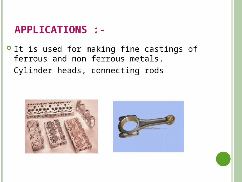
APPLICATIONS :-
It is used for making fine castings of ferrous and non ferrous metals.
Cylinder heads, connecting rods
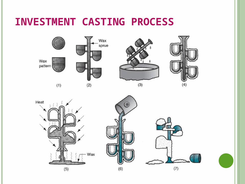
INVESTMENT CASTING PROCESS
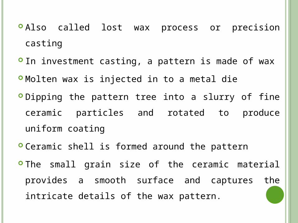
Also called lost wax process or precision casting
In investment casting, a pattern is made of wax
Molten wax is injected in to a metal die
Dipping the pattern tree into a slurry of fine ceramic
particles and rotated to produce uniform coating
Ceramic shell is formed around the pattern
The small grain size of the ceramic material provides a
smooth surface and captures the intricate details of the
wax pattern.
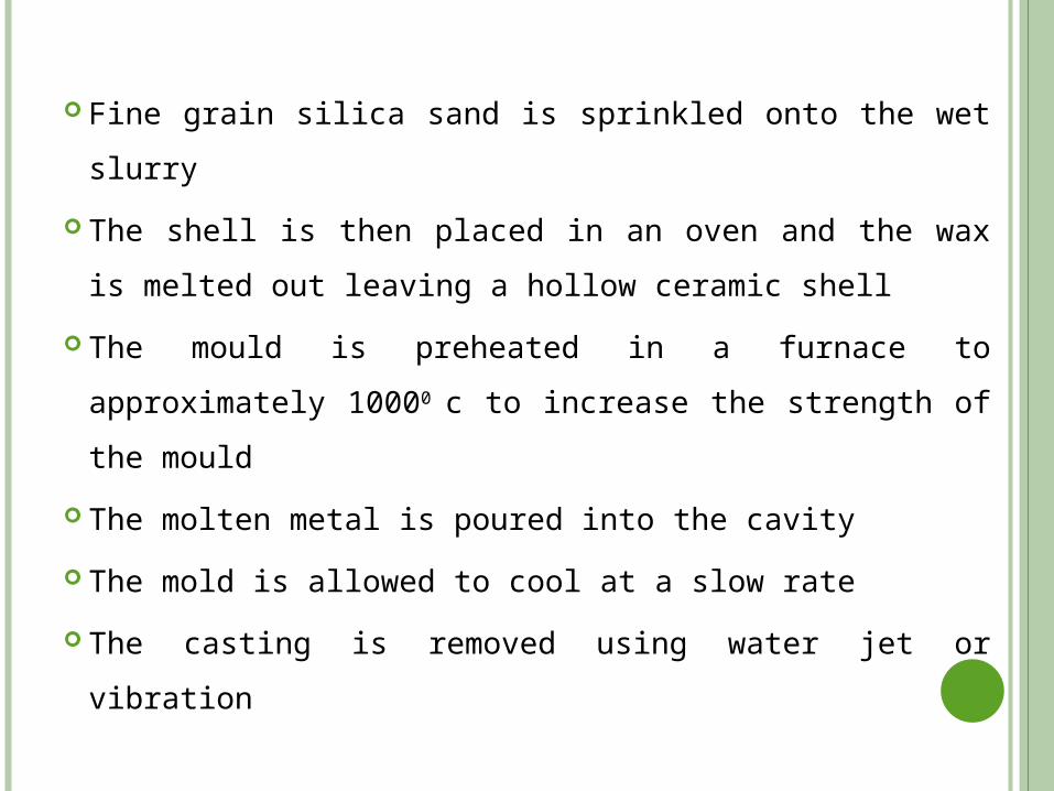
Fine grain silica sand is sprinkled onto the wet slurry
The shell is then placed in an oven and the wax is melted
out leaving a hollow ceramic shell
The mould is preheated in a furnace to approximately
10000 c to increase the strength of the mould
The molten metal is poured into the cavity
The mold is allowed to cool at a slow rate
The casting is removed using water jet or vibration
ADVANTAGES :- Can form complex shapes High strength parts Very good surface finish & accuracy Many material options Little need for secondary machining
LIMITATIONS :- Time consuming process High labor cast High tooling cost
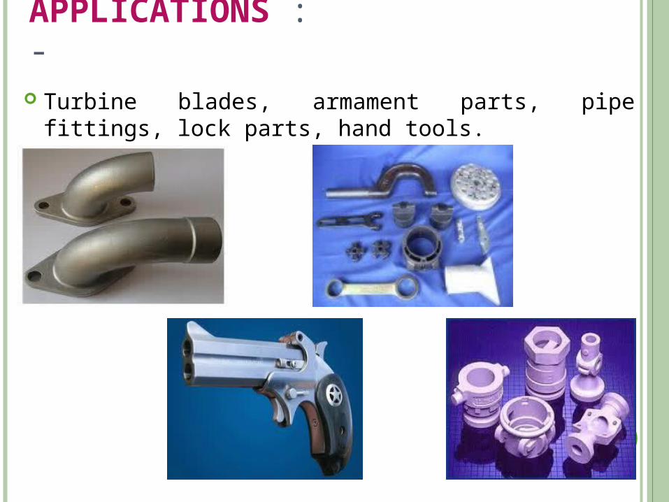
APPLICATIONS :- Turbine blades, armament parts, pipe fittings, lock parts, hand
tools.
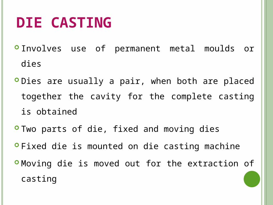
DIE CASTING
Involves use of permanent metal moulds or dies
Dies are usually a pair, when both are placed together the
cavity for the complete casting is obtained
Two parts of die, fixed and moving dies
Fixed die is mounted on die casting machine
Moving die is moved out for the extraction of casting
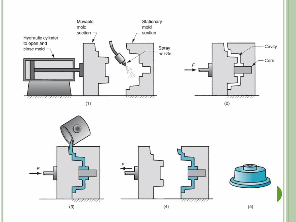
Initially the two dies are apart
Lubricant is sprayed on the dies
The two dies are closed by clamping them together
Required amount of molten metal is injected in to the die
at high pressure
After the solidification the die is opened and casting is
ejected
Types of die casting machines
1. Hot chamber machines
a. Operated by plunger
b. Operated by compressed air
2. Cold chamber machine
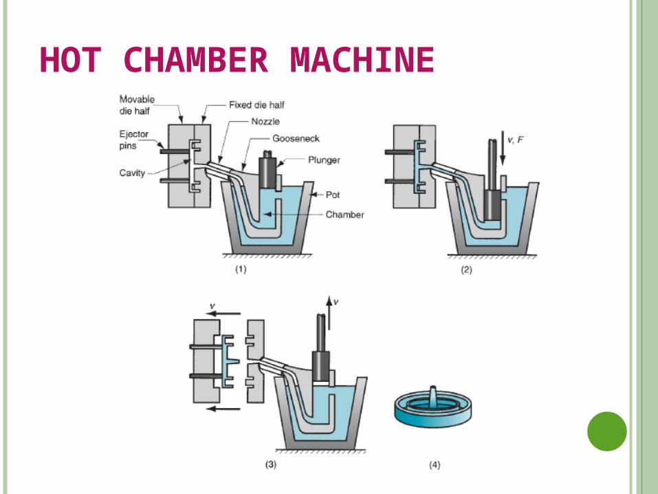
HOT CHAMBER MACHINE
It consists of mainly a hot chamber and a gooseneck type
metal container immersed in the holding furnace containing
molten metal
The plunger develops necessary pressure for forcing the
metal in the die cavity
After the solidification, the casting is ejected at a rapid rate
and the same time plunger moves up as a result it uncovers
the port and molten metal enters into the cylinder
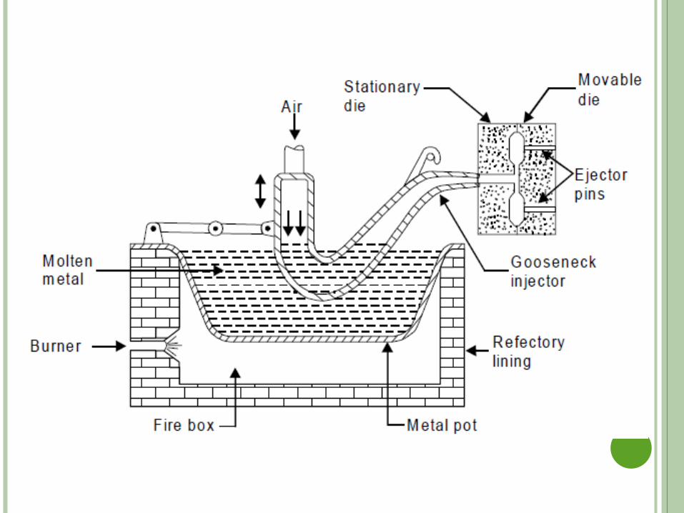
AIR OPERATED MACHINE
In this machine, a suitable mechanism is used to raise or
lower the gooseneck
When gooseneck is lowered it receives the molten metal
from the pot
Then it is raised and held in position against nozzle
Compressed air is blown in to the gooseneck which forces
the metal to fill the die cavity
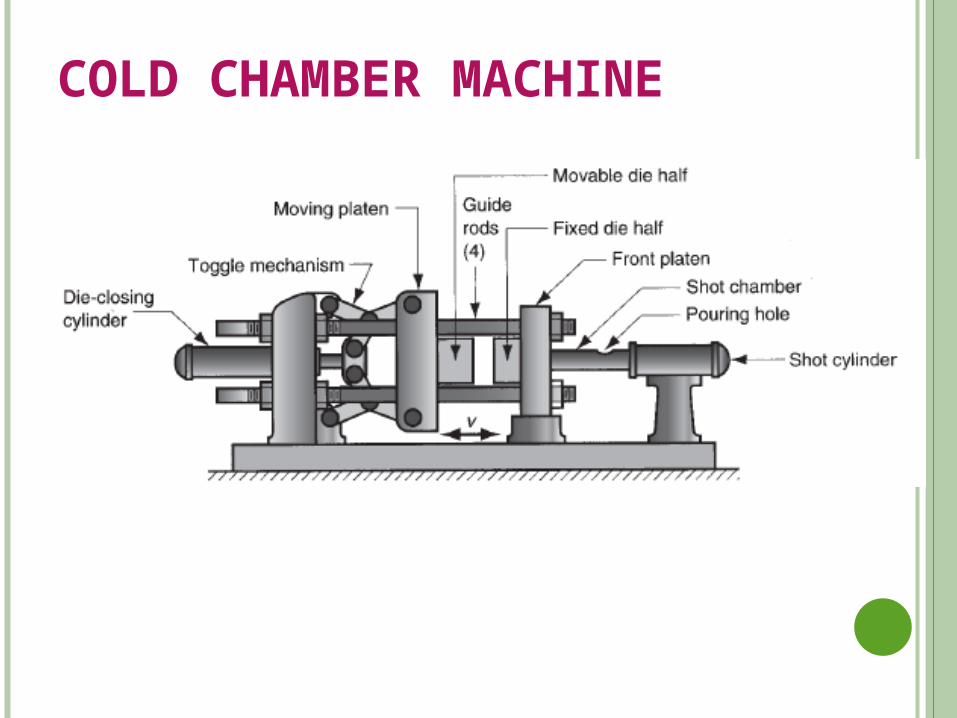
COLD CHAMBER MACHINE
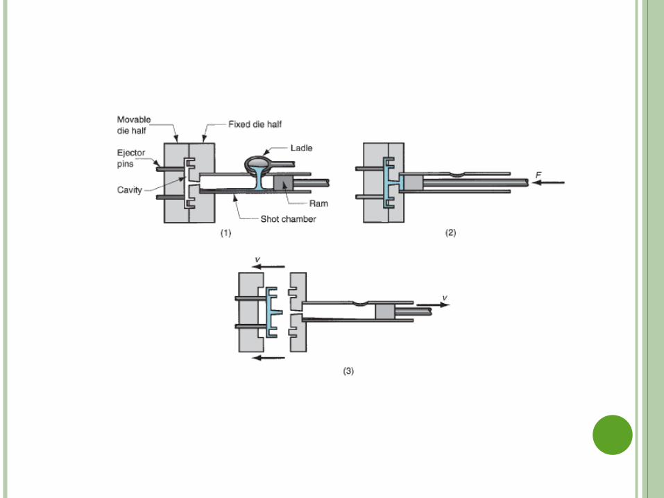
Employed for the alloys of aluminium, magnesium and
copper
Metal is melted in a separate furnace then transferred to the
injection cylinder of the die casting machine
Molten metal is injected into the die cavity using a plunger
operated hydraulically
Has a longer operating cycle
ADVANTAGES
1. Because of the use of the movable cores, It is possible to fairly
obtain the complex shapes
2. Very small thickness can be easily filled because the liquid
metal is injected at high pressures
3. Because of the metallic dies very good surface finish can be
obtained
4. The dies has the long life which is of the order of 300000
pieces
5. It is very economical for large scale production
LIMITATIONS
1. The max. size of the casting is limited. 4kg to 15kg
2. This is not suitable for all materials
3. The dies and machines are very expensive
APPLICATIONS
Carburetors, Crank cases, magnetos, Parts of scooters &
motor cycles, zip fasteners and decorative items on
automobiles.
CENTRIFUGAL CASTING
The mould is rotated rapidly about its neutral axis.
Because of the centrifugal force, a continuous pressure will
be acting on the metal as it solidifies
The slag, oxides and inclusions being lighter get separated
from the metal and segregates towards the centre
Best suited for mass production
Types of centrifugal casting are
1. True centrifugal casting
2. Semi centrifugal casting
3. centrifuging
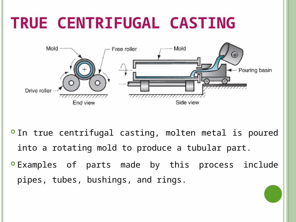
TRUE CENTRIFUGAL CASTING
In true centrifugal casting, molten metal is poured into a
rotating mold to produce a tubular part.
Examples of parts made by this process include pipes, tubes,
bushings, and rings.
The products are hollow cylindrical in shape
A hollow cylindrical mould rotates about an axis common
to both casting and the mould
Axis of rotation may be horizontal, vertical or inclined
The mold used for this process may be either permanent
type or a sand mold
Force upto 50 to 100 times of gravity are developed
The molding flask is properly rammed with sand and is
dynamically balanced to reduce the vibrations during
casting process
The finished flask is mounted on the rollers and the mold is
rotated
Molten metal is poured in to the mold through the movable
pouring basin
The thickness of the pipe depends on the amount of metal
poured
After pouring, the mold is rotated till the metal solidifies to
the requisite form
Then the mold is replaced by new mold
Metal molds can also be used for large quantity production
Very long pipes are cast with horizontal axis where as short
pipes are cast by vertical axis
SEMI-CENTRIFUGAL CASTING
• It is similar to true centrifugal casting but only with a difference
that a central core is used to form the inner surface.
• This casting process is generally used for articles which are more
complicated than those possible in true centrifugal casting,
• Axisymmetric in nature products are produced
• Centrifugal force is used to produce solid castings, rather than
tubular parts
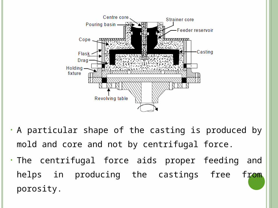
• A particular shape of the casting is produced by mold and
core and not by centrifugal force.
• The centrifugal force aids proper feeding and helps in
producing the castings free from porosity.
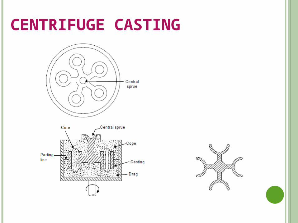
CENTRIFUGE CASTING
In centrifuge casting, the mold is designed with part cavities
located away from the axis of rotation
The molten metal poured into the mold is distributed to
these cavities by centrifugal force.
The process is used for smaller parts, and radial symmetry
of the part is not a requirement as it is for the other two
centrifugal casting methods.
ADVANTAGES
1. The mechanical properties of centrifugally cast jobs are
better compared to other processes
2. No cores are required for making concentric holes
3. There is no need for gates and runners
4. No slag and oxide inclusions
LIMITATIONS
1. Only certain shapes which are ax symmetric and having
can be produced
2. The equipment is expensive and thus is suitable for large
quantities
APPLICATIONS
1. Cast iron pipes, spigot ends or flanged ends
2. Pipes, barrels-gun, street lamp posts & other hollow axis-
symmetric components
CASTING DEFECTS
Any irregularities during casting process causes defects in
castings
The various defects are
1. Gas defects
2. Shrinkage defects
3. Molding material defects
4. Pouring metal defects
5. Metallurgical defects
GAS DEFECTS
1. Blow holes and open blows Spherical, flattened or elongated cavities present inside
the casting or on the surface of the casting Moisture left in the mold and core
2. Air Inclusions Due to absorption of gases by the molten metal in the
furnace, they cannot escape and weaken the mold during casting.
Due to high pouring temperatures
3. Pin hole porosity
Caused by hydrogen in the molten metal
Hydrogen While leaving the solidifying metal, it causes
very small dia and long pinholes showing the path of
escape
Pin holes causes Leakage of fluids under high operating
pressure.
This is mainly due to High pouring temperatures.
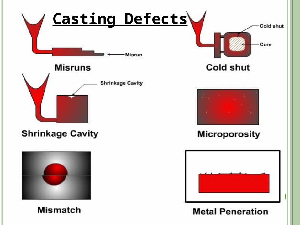
SHRINKAGE CAVITIES
Caused by the liquid shrinkage occurring during solidification
process
To compensate this proper feeding of liquid metal is requried
MOULDING MATERIAL DEFECTS
1. Cuts and washes
Appear as rough spots and areas of excess metal and caused by erosion of Molding sand by the flowing molten metal
2. Runout
Caused when molten metal leaks out of the mold
Caused because of faulty mould making
3. Swell
Refers to the condition of enlargement of mould cavity when the molten metal is poured into the mould
Caused by insufficient ramming or by pouring the metal too rapidly
4. Drop
The dropping of loose moulding sand or lumps from the cope surface into the mould cavity is responsible for this defect this is due to improper ramming of the cope flask.
POURING METAL DEFECTS1. Miss runs and cold shuts
Miss run is Caused when the metal is unable to fill the mould cavity completely and thus leaves unfilled cavities
Cold shut is Caused when two cold metal stream of molten metal meet at the junction and do not fuse together
2. Slag formation
During melting process flux is added to remove undesirable oxides and impurities present in the metal
The slag should be removed from the ladle before pouring
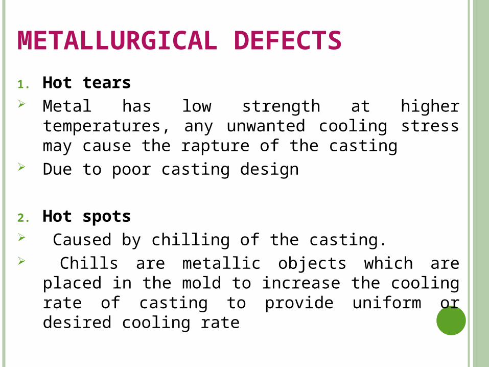
METALLURGICAL DEFECTS
1. Hot tears Metal has low strength at higher temperatures, any
unwanted cooling stress may cause the rapture of the casting
Due to poor casting design
2. Hot spots Caused by chilling of the casting. Chills are metallic objects which are placed in the mold
to increase the cooling rate of casting to provide uniform or desired cooling rate
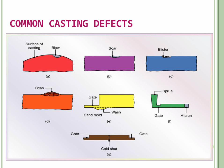
COMMON CASTING DEFECTS
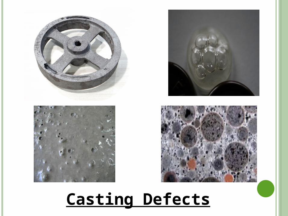
Casting Defects
Casting Defects
PART 2 WELDING
Welding is a process of joining two or more pieces of the same or dissimilar materials (metals) by the application of heat and pressure.
APPLICATIONS: Boilers, pressure vessels, ships, bridges, storage tanks, pipelines,
railway coaches, missiles & rockets, nuclear reactors, chemical plants, automobile parts, press frames & water turbines etc.
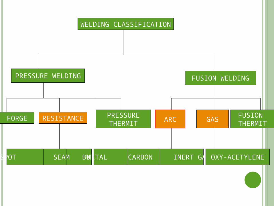
FUSION WELDINGPRESSURE WELDING
WELDING CLASSIFICATION
FORGE RESISTANCE PRESSURETHERMIT
ARC GASFUSION THERMIT
SPOT SEAM BUTT METAL CARBON INERT GAS OXY-ACETYLENE
DIFFERENCES BETWEEN PRESSURE & FUSION WELDING
In Pressure welding the joint area of the base metal is heated to plastic state & forced together by external pressure without addition of filler material.
In fusion welding the joint area of the part is heated to fusion state (molten) & a joint is formed as a result of solidification. In this case filler material is used during welding process.
ADVANTAGES
1. Welding is more economical and is much faster process as
compared to other processes (riveting, bolting, casting etc.)
2. Welding, if properly controlled results permanent joints having
strength equal or sometimes more than base metal.
3. Large number of metals and alloys both similar and dissimilar
can be joined by welding.
4. General welding equipment is not very costly.
5. Portable welding equipment can be easily made available.
DISADVANTAGES
1. It results in residual stresses and distortion of the work pieces.
2. Welded joint needs stress relieving and heat treatment.
3. Welding gives out harmful radiations (light), fumes and spatter.
4. Jigs, and fixtures may also be needed to hold and position the parts to
be welded
5. Skilled welder is required for production of good welding
6. Heat during welding produces metallurgical changes as the structure
of the welded joint is not same as that of the parent metal.
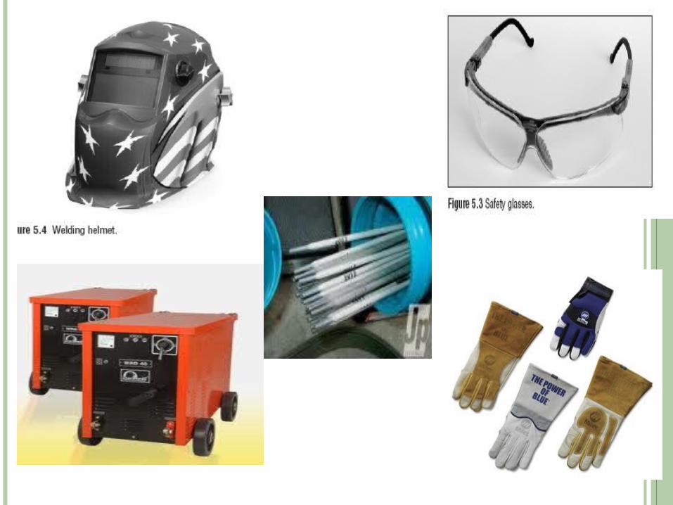
ARC WELDING EQUIPMENT :-
Based on current source:
AC machines : Transformer
DC machines : Transformer with DC rectifier Electrodes Electrode holder Cables Safety devices Tools
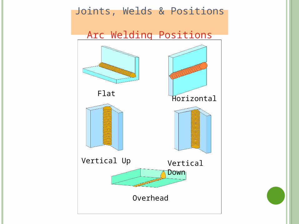
Joints, Welds & Positions Arc Welding Positions
HorizontalFlat
Vertical Up
Overhead
Vertical Down
ARC WELDING
This the most efficient method of welding where the source of heat is an electric arc.
This type of welding uses a power supply (either DC or AC) to create an electric arc between an electrode and the base/parent material to melt the metals at the welding point.
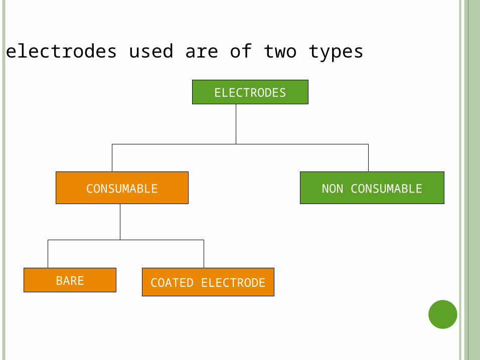
ELECTRODES
CONSUMABLE NON CONSUMABLE
BARE COATED ELECTRODE
The electrodes used are of two types
CONSUMABLE ELECTRODES:
These are made up of various metals depending up on the purpose and chemical composition of the metals to be welded.They may be made of steel, cast iron, copper, brass, bronze or aluminium.When the arc is obtained by the consumable electrode, the weld metal under the arc melts. Here the filler metal and heat are both built into a single electrode.
NON CONSUMABLE ELECTRODES:
These are made of carbon, graphite or tungsten can also be used for arc welding.Here the filler metal required has to be deposited through a separate filler rod. Thus in this method the proper control of heat and filler metal is possible as both are separately controlled.
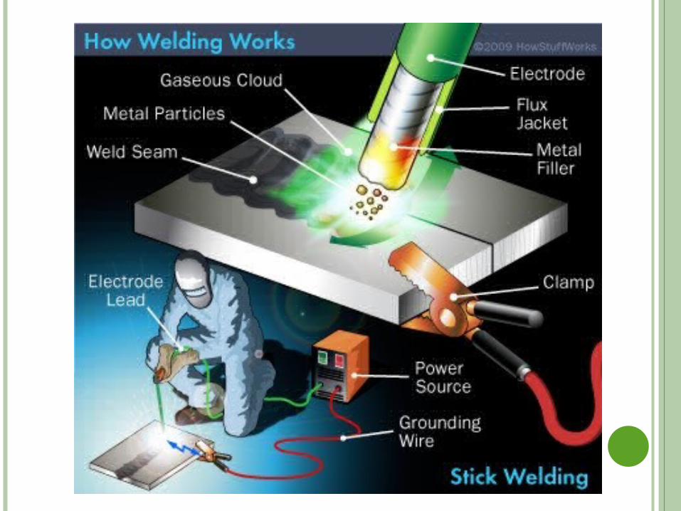
SHIELDED METAL ARC WELDING (SMAW)
Also called Manual Metal Arc Welding (MMAW)
It uses a consumable electrode coated in flux to lay the weld.
The flux coating of electrode decomposes due to arc heat and serves
many functions, like weld metal protection, arc stability etc.
An AC or DC power supply is used to form an electric arc between
the electrode and the metals to be joined.
Inner core of the electrode supply the filler material for making a
weld.
Because of its versatility of process and simplicity of equipment and
operation, it is the most extensively used welding process.
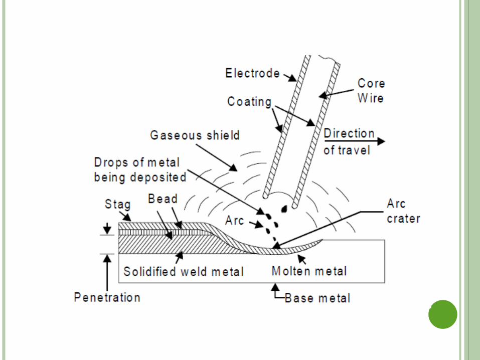
OPERATION:
The arc is formed by momentarily touching the tip of
the electrode unto the plate.
Then lifting the electrode to give a gap of 3 mm – 6 mm between the
tip and the plate.
When the electrode touches the plate, current commences to flow.
As the electrode melts, the flux covering disintegrates, giving off
shielding gases that protect the weld area from atmospheric gases.
In addition the flux provides molten slag which covers the filler metal
as it travels from the electrode to the weld pool.
After the deposited weld gets solidified (hardened) the slag must be
chipped away to reveal the finished weld.
APPLICATIONS • Almost all the commonly employed metals and their alloys can
be welded by this process.• Is used both as a fabrication process and for maintenance and
repair jobs.• The process finds applications in
(a) Building and Bridge construction
(b) Automotive and aircraft industry, etc
(c) Air receiver, tank, boiler and pressure vessel fabrication
(d) Ship building
(e) Pipes and
(f) Penstock joining
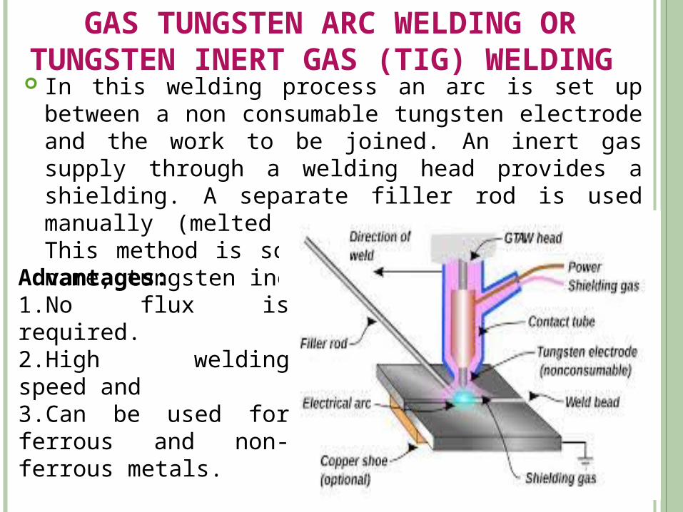
GAS TUNGSTEN ARC WELDING OR TUNGSTEN INERT GAS (TIG) WELDING
In this welding process an arc is set up between a non consumable tungsten electrode and the work to be joined. An inert gas supply through a welding head provides a shielding. A separate filler rod is used manually (melted in the arc), if needed. This method is sometimes called by its old name, tungsten inert gas (TIG) welding.
Advantages:1.No flux is required.2.High welding speed and 3.Can be used for ferrous and non-ferrous metals.
GAS METAL ARC (GMAW) WELDING OR METAL INERT GAS (MIG) WELDING
This process is also called as metal inert gas (MIG) welding. A consumable metal is fed from a reel through gaseous shield to
serve as an electrode. An arc is established between the wire electrode and the work piece. The wire constantly melted to form the molten weld pool which is
always converted under the gaseous shield. This process gives very clean welds in thicker work materials at
quite high rates. For example, metals 5 mm to 50 mm thick can be welded with a
metal deposition rate up to 7 kg per hour or more. Shielding gases may be inert ones like argon and helium and their
mixtures with some other gases; or carbon-dioxide. When CO2 is used as a shielding gas (for welding low carbon steels) the process is sometimes called as metal active gas (MAG) welding.
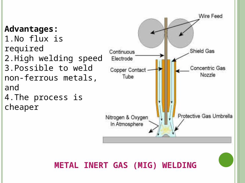
Advantages:1.No flux is required2.High welding speed3.Possible to weld non-ferrous metals, and4.The process is cheaper
METAL INERT GAS (MIG) WELDING
GAS WELDING :- Gas welding is classified under the fusion welding process.
Heat source is a gas flame
Different gas combination can be used for producing the flame.
Usually the mixture of oxygen and acetylene is used for welding purposes, producing temperatures in the range of 3200-3300°C.
In gas welding the two surfaces to be welded are properly prepared and placed near each temperature by heat from the flame and the weld is completed by supplying additional metal as the filler metal obtained by a filler rod.
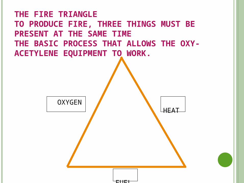
FUEL
HEAT
THE FIRE TRIANGLETO PRODUCE FIRE, THREE THINGS MUST BE PRESENT AT THE SAME TIMETHE BASIC PROCESS THAT ALLOWS THE OXY-ACETYLENE EQUIPMENT TO WORK.
OXYGEN
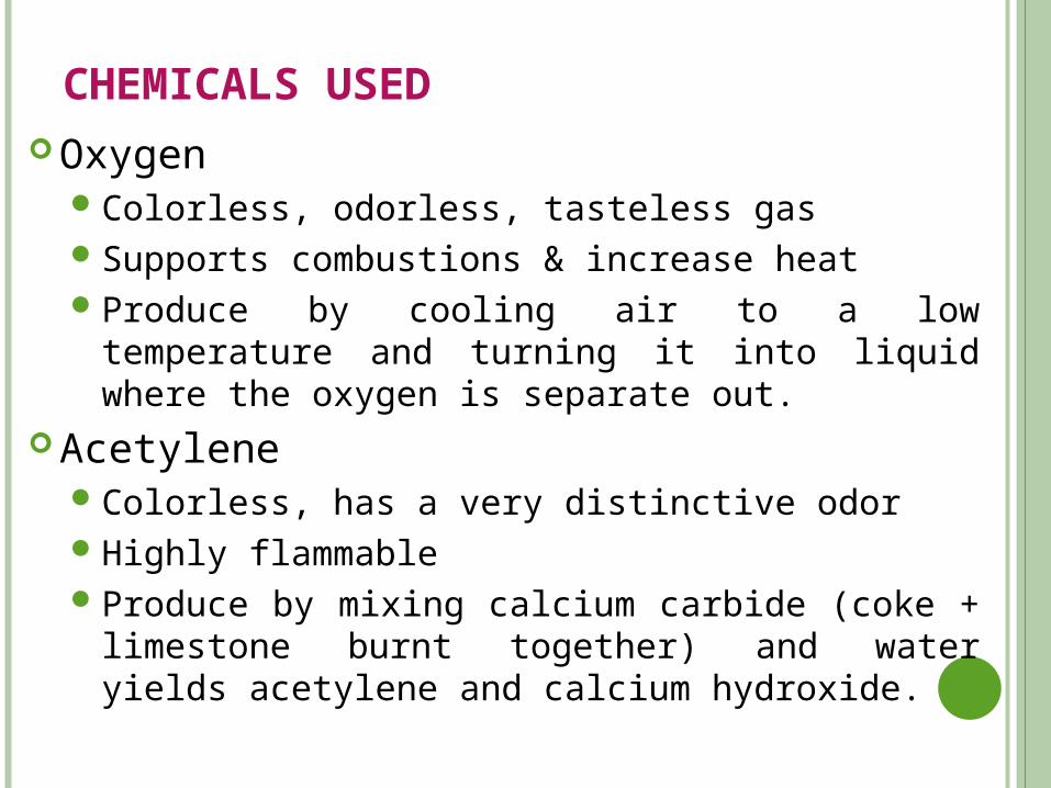
CHEMICALS USED Oxygen
Colorless, odorless, tasteless gasSupports combustions & increase heatProduce by cooling air to a low temperature and turning it
into liquid where the oxygen is separate out. Acetylene
Colorless, has a very distinctive odorHighly flammableProduce by mixing calcium carbide (coke + limestone burnt
together) and water yields acetylene and calcium hydroxide.
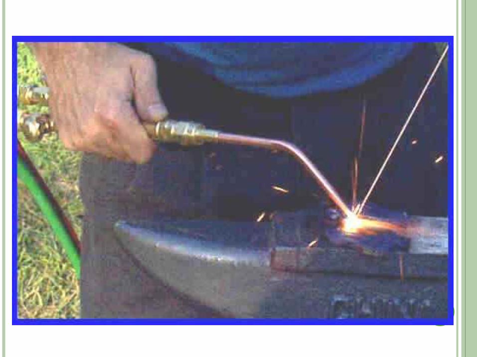
OXY-ACETYLENE GAS WELDING :-
It develops in 1900’s
It utilizes the heat generated by the combustion of oxy-acetylene
Burning acetylene in the presence of oxygen.
At the tip of the nozzle.
The temperature of the oxy-acetylene flame is 3250oC
Heat is to melt parent metal to form a weld pool.
Filler is added separately.
Torch moved to achieve a required length.
Molten metal is protected by the gaseous products of the flame.
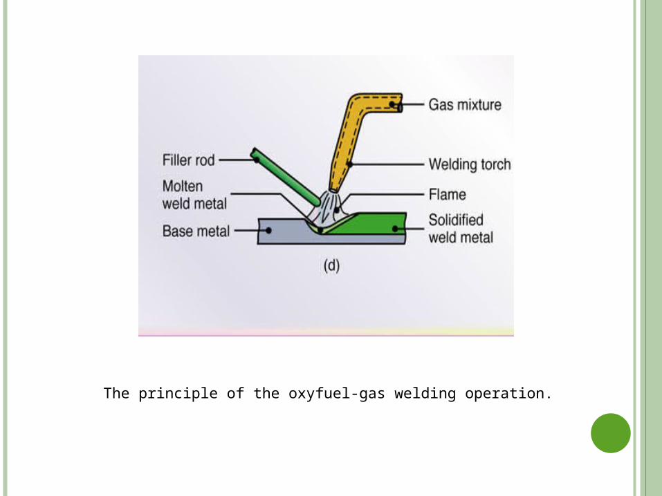
The principle of the oxyfuel-gas welding operation.
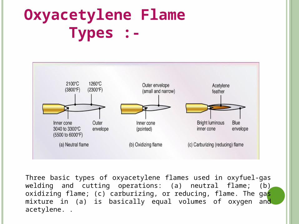
Oxyacetylene Flame Types :-
Three basic types of oxyacetylene flames used in oxyfuel-gas welding and cutting operations: (a) neutral flame; (b) oxidizing flame; (c) carburizing, or reducing, flame. The gas mixture in (a) is basically equal volumes of oxygen and acetylene. .
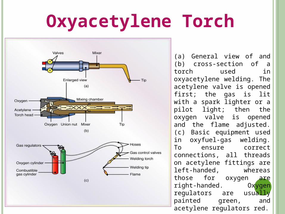
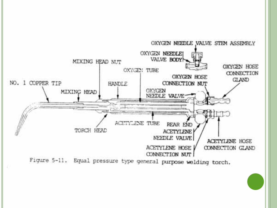
Oxyacetylene Torch
(a) General view of and (b) cross-section of a torch used in oxyacetylene welding. The acetylene valve is opened first; the gas is lit with a spark lighter or a pilot light; then the oxygen valve is opened and the flame adjusted. (c) Basic equipment used in oxyfuel-gas welding. To ensure correct connections, all threads on acetylene fittings are left-handed, whereas those for oxygen are right-handed. Oxygen regulators are usually painted green, and acetylene regulators red.
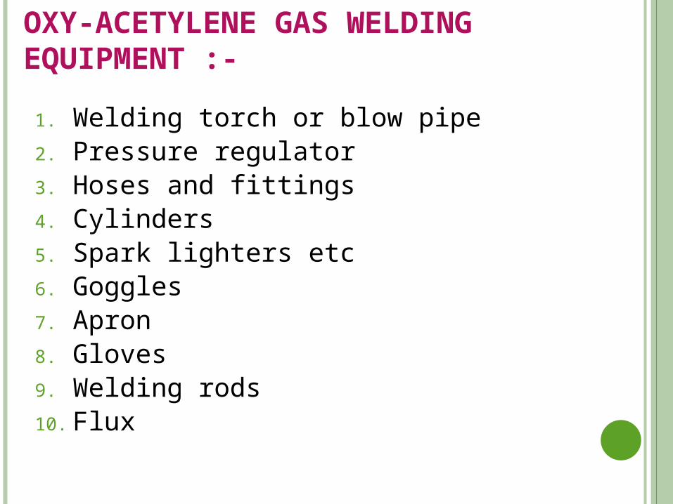
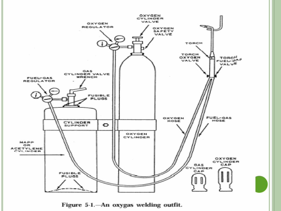
OXY-ACETYLENE GAS WELDING EQUIPMENT :-
1. Welding torch or blow pipe2. Pressure regulator3. Hoses and fittings4. Cylinders5. Spark lighters etc6. Goggles7. Apron8. Gloves9. Welding rods10. Flux
OXYGEN CYLINDER:-
pure oxygen produced by liquefaction process.
Made up of steel
Painted in black colour
It contains oxygen at a pressure of 175 bar
It can store 7m3 of gas.
ACETYLENE CYLINDER :-
It contains acetylene product of carbon carbide & water.
Made up of steel
Painted in maroon colour.
Cylinder contains acetylene at 15 bar
The capacity of cylinder is 6m3 of gas.
TYPE OF ACETYLENE FLAME :-
Depending on the relative amount of oxygen & acetylene , the gas flame is classified into three types.
Oxidising flame
Neutral flame
Reducing (carburising) flame
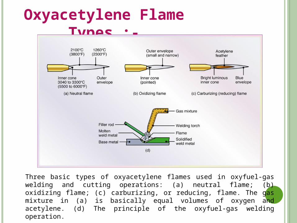
Oxyacetylene Flame Types :-
Three basic types of oxyacetylene flames used in oxyfuel-gas welding and cutting operations: (a) neutral flame; (b) oxidizing flame; (c) carburizing, or reducing, flame. The gas mixture in (a) is basically equal volumes of oxygen and acetylene. (d) The principle of the oxyfuel-gas welding operation.
ADVANTAGES :- The relative cost of the equipment is low.
No electricity is required for this process.
Can be used for welding in all positions.
Can be used on both thick and thin materials, which makes it a very versatile process.
Very clean, producing no slag or spatter that must be removed from the weld.
Produces high quality welds when done properly.
LIMITATIONS :- The materials that can be welded are limited primarily to ferrous
materials.
Can create a “Hot Zone”, fire hazard, because of the sparks and flame generated in the welding process.
Requires the handling of high pressure gases.
The process can often be slow when compared to other types of welding processes.
high temperature flame only with oxy-acetylene .
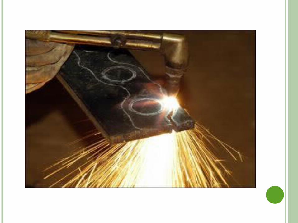
OXY-FUEL GAS FLAME CUTTING :- It is oxygen cutting process It is used for separating or cutting the a part from the whole. It uses cutting torch to generate flame. Oxy-acetylene flame preheats the metal to be cut. After a spot area along the line of cut is heated to ignition temp
(900oC). Thin jet of high purity of oxygen at pressure of 300kpa is then
directed or shot at this heated spot . The jet quickly penetrates through the steel by cutting it. The torch moves progressively forward over the metal surface.
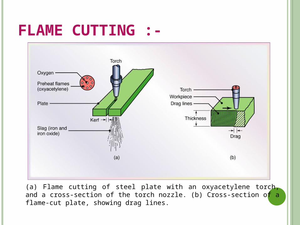
(a) Flame cutting of steel plate with an oxyacetylene torch, and a cross-section of the torch nozzle. (b) Cross-section of a flame-cut plate, showing drag lines.
FLAME CUTTING :-
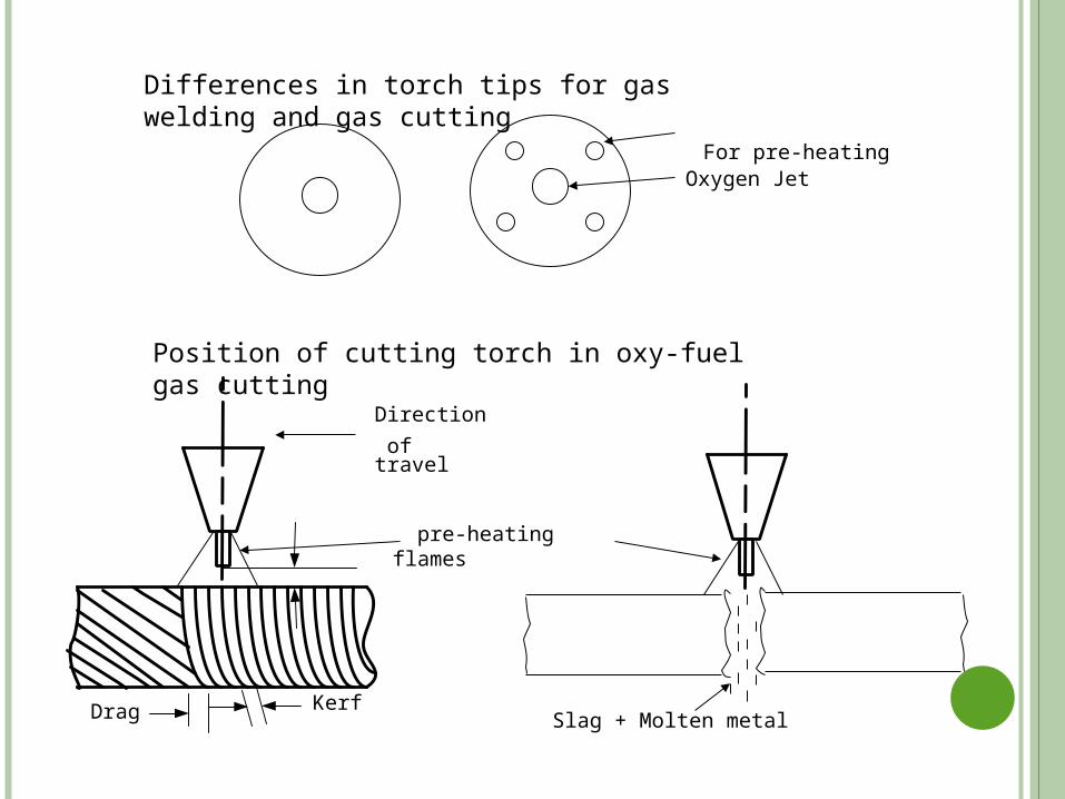
pre-heating flames
Oxygen Jet
Differences in torch tips for gas welding and gas cutting
Slag + Molten metal
For pre-heating
Direction
of travel
Position of cutting torch in oxy-fuel gas cutting
Drag Kerf
ADVANTAGES :-
(i) Shapes and sizes difficult to be machined by mechanical methods can be easily cut by flame cutting.
(ii) The process is faster than mechanical cutting methods.
(iii) The cost of flame cutting is low as compared to that on a machine tool, i.e. mechanical cutting machine.
(iv) Flame cutting equipment being portable also, can be used for the field work.
(v) Multitorch machines can cut a number of pieces simultaneously
DISADVANTAGES OF FLAME CUTTING :-
(i) Flame cutting is limited to the cutting of steels and cast iron.
(ii) As compared to mechanical cutting, the dimensional tolerances are poor.
(iii) The place of cutting needs adequate ventilation and proper fume control.
(iv) The expelled red hot slag and other particles present fire and burn hazards to plant and workers.
USES :- (i) To prepare edges of plates for bevel and groove weld joint
designs.
(ii) To cut small sized work pieces from bigger plates for further processing.
(iii) To cut rivets, gates and risers from castings.
(iv) To cut many layers of thin sheets at the same time (stack cutting) to reduce both time and cost for production work.
(v) To pierce holes and slots in steel plates.
RESISTANCE WELDING :-
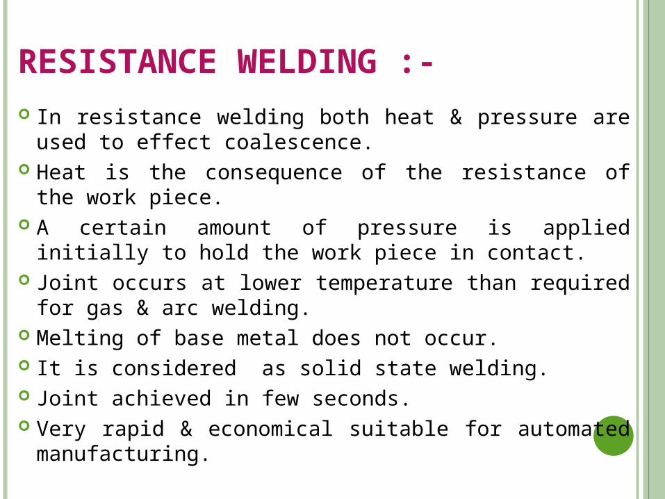
In resistance welding both heat & pressure are used to effect coalescence.
Heat is the consequence of the resistance of the work piece. A certain amount of pressure is applied initially to hold the work
piece in contact. Joint occurs at lower temperature than required for gas & arc
welding. Melting of base metal does not occur. It is considered as solid state welding. Joint achieved in few seconds. Very rapid & economical suitable for automated manufacturing.
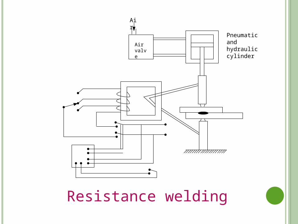
Air valve
Air
Pneumatic and hydraulic cylinder
Resistance welding
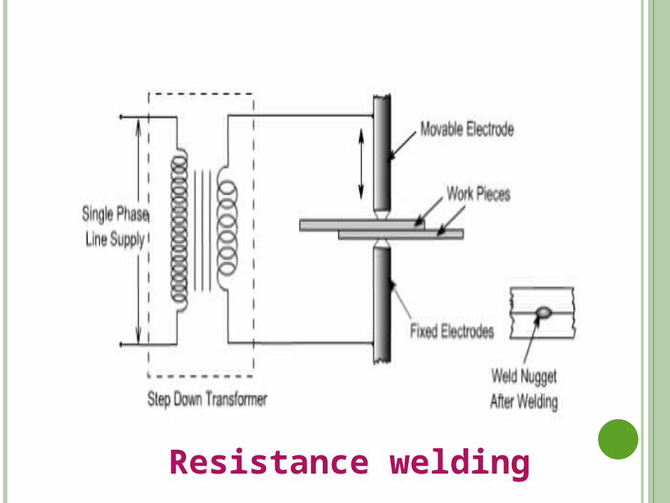
Resistance welding
FACTORS EFFECTING THE RESISTANCE WELDING :-
Heat Resistance Temperature Pressure Current control
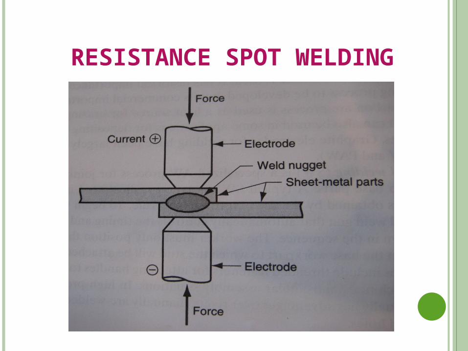
RESISTANCE SPOT WELDING
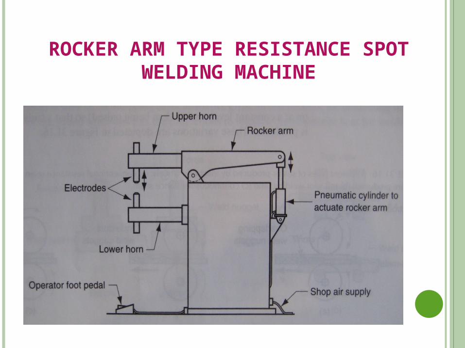
ROCKER ARM TYPE RESISTANCE SPOT WELDING MACHINE
BRAZING :-
Low melting point material is melted & drawn into the space between two solid surfaces.
Joining of metals by heat & filler material.
Melting point of filler material above the 450o C & below metals being joined.
COMPARISON WITH WELDING :-
Composition of brazing alloy is different from the base metal.
Melting point of brazing alloy is lower than of the base metal.
Strength of the brazing alloy is substantially lower than the base metal.
STRENGTH OF BRAZING :-The bonding is enhanced by cleanly surfaces, proper
clearance, good wetting,& good fluidity.
Bond strength
Wettability
Fluidity
APPLICATIONS :-
Brazing is applicable to cast and wrought irons, steels, Cu and Cu alloys, Al and Al alloys, Mg and Mg alloys and to so many other materials.
Brazing is used in place of welding where special metallurgical characteristics of metals have to be preserved after joining.
Brazing can join(a) Cast metals to wrought metals. (b) Non-metals to metals. (c) Dissimilar metals. (d) Porous metal components
FREQUENTLY USED BRAZING MATERIALS :-
Copper Silver Copper zinc alloys Aluminum –silicon alloys
SOLDERING :-
Soldering is similar to brazing operation. Filler material has a low melting temperature below
than the 450o C Bond strength relatively low Bonding being the result of adhesion between the
solder & the parent metal. Most solder material are alloy of lead & tin,tin-
antimony,tin-zinc.
Recommended