HE-800B ELECTRONIC DIRECT DRIVE LOCKSTITCH BUTTON HOLER
Please read this manual before using the machine. Please keep this manual within easy reach for quick reference.
This basic operation manual describes basic operations including sewing machine operations. For cleaning, standard adjustments and more details, please refer to the instruction manual contained in the Document CD.
Basic Operation Manual

Thank you very much for buying a BROTHER sewing machine. Before using your new machine, please read the safety instructions below and the explanations given in the instruction manual. With industrial sewing machines, it is normal to carry out work while positioned directly in front of moving parts such as the needle and thread take-up lever, and consequently there is always a danger of injury that can be caused by these parts. Follow the instructions from training personnel and instructors regarding safe and correct operation before operating the machine so that you will know how to use it correctly.
HE-800B

SAFETY INSTRUCTIONS [1] Safety indications and their meanings This instruction manual and the indications and symbols that are used on the machine itself are provided in order to ensure safe operation of this machine and to prevent accidents and injury to yourself or other people. The meanings of these indications and symbols are given below.
Indications DANGER The instructions which follow this term indicate situations where failure to follow the
instructions will result in death or serious injury.
WARNING The instructions which follow this term indicate situations where failure to follow the instructions could result in death or serious injury.
CAUTION The instructions which follow this term indicate situations where failure to follow the instructions may result in minor or moderate injury.
Symbols
・・・・・・ This symbol ( ) indicates something that you should be careful of. The picture inside the triangle indicates the nature of the caution that must be taken. (For example, the symbol at left means “beware of injury”.)
・・・・・・ This symbol ( ) indicates something that you must not do.
・・・・・・ This symbol ( ) indicates something that you must do. The picture inside the circle indicates the nature of the thing that must be done. (For example, the symbol at left means “you must make the ground connection”.)
HE-800B i

[2] Notes on safety DANGER
Wait at least 5 minutes after turning off the power switch and disconnecting the power cord from the wall outlet before opening the control box cover. Touching areas where high voltages are present will result in serious injury from electric shocks.
WARNING Do not allow any liquids to get onto this sewing machine, otherwise fire, electric shocks or operating problems may occur. If any liquid gets inside the sewing machine (machine head or control box), immediately turn off the power and disconnect the power plug from the electrical outlet, and then contact the place of purchase or a qualified technician.
CAUTION Environmental requirements
Use the sewing machine in an area which is free from sources of strong electrical noise such as electrical line noise or static electric noise. Sources of strong electrical noise may cause problems with correct operation. Any fluctuations in the power supply voltage should be within ±10% of the rated voltage for the machine. Voltage fluctuations which are greater than this may cause problems with correct operation. The power supply capacity should be greater than the requirements for the sewing machine’s power consumption. Insufficient power supply capacity may cause problems with correct operation.
The ambient temperature should be within the range of 5°C to 35°C during use. Temperatures which are lower or higher than this may cause problems with correct operation. The relative humidity should be within the range of 45% to 85% during use, and no dew formation should occur in any devices. Excessively dry or humid environments and dew formation may cause problems with correct operation. In the event of an electrical storm, turn off the power and disconnect the power cord from the wall outlet. Lightning may cause problems with correct operation.
Installation Machine installation should only be carried out by a qualified technician. Contact your Brother dealer or a qualified electrician for any electrical work that may need to be done. The sewing machine weighs approximately 56 kg. The installation should be carried out by two or more people. Do not connect the power cord until installation is complete, otherwise the machine may operate if the treadle is depressed by mistake, which could result in injury. Use both hands to hold the machine head when tilting it back or returning it to its original position. If only one hand is used, the weight of the machine head may cause your hand to slip, and your hand may get caught. Be sure to connect the ground. If the ground connection is not secure, you run a high risk of receiving a serious electric shock, and problems with correct operation may also occur.
All cords should be secured at least 25 mm away from any moving parts. Furthermore, do not excessively bend the cords or secure them too firmly with staples, otherwise there is the danger that fire or electric shocks could occur. Install the safety covers to the machine head and motor. If using a work table which has casters, the casters should be secured in such a way so that they cannot move. Be sure to wear protective goggles and gloves when handling the lubricating oil and grease, so that they do not get into your eyes or onto your skin, otherwise inflammation can result. Furthermore, do not drink the oil or eat the grease under any circumstances, as they can cause vomiting and diarrhea. Keep the oil out of the reach of children.
HE-800B ii

CAUTION Sewing
This sewing machine should only be used by operators who have received the necessary training in safe use beforehand. The sewing machine should not be used for any applications other than sewing. Be sure to wear protective goggles when using the machine. If goggles are not worn, there is the danger that if a needle breaks, parts of the broken needle may enter your eyes and injury may result. Turn off the power switch at the following times, otherwise the machine may operate if the treadle is depressed by mistake, which could result in injury. • When replacing the needle and bobbin • When not using the machine and when leaving the
machine unattended Use threading mode or turn off the power first in order to carry out threading.
If using a work table which has casters, the casters should be secured in such a way so that they cannot move. Attach all safety devices before using the sewing machine. If the machine is used without these devices attached, injury may result. Do not touch any of the moving parts or press any objects against the machine while sewing, as this may result in personal injury or damage to the machine. If an error occurs in machine operation, or if abnormal noises or smells are noticed, immediately turn off the power switch. Then contact your nearest Brother dealer or a qualified technician. If the machine develops a problem, contact your nearest Brother dealer or a qualified technician.
Cleaning Turn off the power switch before carrying out cleaning, otherwise the machine may operate if the treadle is depressed by mistake, which could result in injury.
Be sure to wear protective goggles and gloves when handling the lubricating oil and grease, so that they do not get into your eyes or onto your skin, otherwise inflammation can result. Furthermore, do not drink the oil or eat the grease under any circumstances, as they can cause vomiting and diarrhea. Keep the oil out of the reach of children.
Maintenance and inspection Maintenance and inspection of the sewing machine should only be carried out by a qualified technician. Ask your Brother dealer or a qualified electrician to carry out any maintenance and inspection of the electrical system. Turn off the power switch and disconnect the power cord from the wall outlet at the following times, otherwise the machine may operate if the treadle is depressed by mistake, which could result in injury. • When carrying out inspection, adjustment and
maintenance • When replacing consumable parts such as the
rotary hook
Turn off the power switch before inserting or removing the plug, otherwise damage to the control box could result. If the power switch needs to be left on when carrying out some adjustment, be extremely careful to observe all safety precautions.
Use both hands to hold the machine head when tilting it back or returning it to its original position. If only one hand is used, the weight of the machine head may cause your hand to slip, and your hand may get caught.
When replacing parts and installing optional accessories, be sure to use only genuine Brother parts. Brother will not be held responsible for any accidents or problems resulting from the use of non-genuine parts. If any safety devices have been removed, be absolutely sure to re-install them to their original positions and check that they operate correctly before using the machine. To prevent accidents and problems, do not modify the machine yourself. Brother will not be held responsible for any accidents or problems resulting from modifications made to the machine.
HE-800B iii

[3] Warning labels
The following warning labels appear on the sewing machine. Please follow the instructions on the labels at all times when using the machine. If the labels have been removed or are difficult to read, please contact your nearest Brother dealer.
1
2
*Safety devices (A) Eye guard (B) Finger guard (C) Thread take-up cover (D) Motor cover (E) Slide cover
3
Be careful to avoid injury from the moving thread take-up.
7
4
Be careful not to get your hands caught when returning the machine head to its original position after it has been tilted.
5
Be careful to avoid injury from the moving cutter.
6
Be sure to connect the ground. If the ground connection is not secure, you run a high risk of receiving a serious electric shock, and problems with correct operation may also occur.
HE-800B iv

Oil tank (accessory)
4732M 4731M
4730M
HE-800B v

CONTENTS
1. NAMES OF MAJOR PARTS ................ 1
2. USEFUL FUNCTIONS FOR OPTIMUM SEWING .............................. 2
3. STANDARD SEWING PATTERN LIST .. 3
4. INSTALLATION .................................... 4 4-1. Table processing diagram .............................. 4 4-2. Installing the control box ................................. 5 4-3. Installing the flange nut................................... 6 4-4. Installing the bed base.................................... 6 4-5. Installing the machine head ............................ 7 4-6. Installing the head rest ................................... 7 4-7. Installing the operation panel ......................... 8 4-8. Installing the oil stopper plate ......................... 9 4-9. Connecting the cords ...................................... 9 4-10. Connecting the ground wire ......................... 12 4-11. Installing the treadle connecting rod ............. 13 4-12. Installing the cotton stand ............................. 14 4-13. Installing the eye guard ................................ 14 4-14. Lubrication .................................................... 15
4-14-1. Lubricating the bed base ................... 15 4-14-2. Lubricating the arm ........................... 15 4-14-3. Lubricating the rotary hook ............... 16
4-15. Connecting the power cord .......................... 16 4-16. Checking the safety switch ........................... 19 4-17. Installing the motor cover ............................. 19 4-18. Installing the auxiliary table .......................... 20
5. PREPARATION BEFORE SEWING ..... 21 5-1. Installing the needle ........................................ 21 5-2. Threading the upper thread ............................ 22 5-3. Winding the lower thread ................................ 24 5-4. Installing the bobbin case ............................... 25 5-5. Thread tension ................................................ 26
5-5-1. Lower thread tension ........................... 26 5-5-2. Upper thread tension ........................... 27 5-5-3. Thread take-up spring height .............. 28 5-5-4. Thread take-up spring tension ............. 28 5-5-5. Adjusting arm thread guide.................. 28
6. USING THE SEWING MACHINE (OPERATION PANEL: BASIC OPERATION) ....................................... 29
6-1. Name and function of each operation panel item ........................................................ 29
6-2. Starting the sewing machine ........................... 31 6-3. Operating the treadle ...................................... 32 6-4. Program setting method .................................. 33
6-4-1. Parameter list ...................................... 35 6-4-2. Setting the length of the hole ............... 41 6-4-3. Buttonhole sewing size ........................ 41 6-4-4. Main restrictions when setting
parameters .......................................... 41 6-5. Rear tack vector shape programs ................... 42 6-6. Underlay programs ......................................... 43 6-7. Cutter operation .............................................. 44 6-8. Copying programs ........................................... 45
7. USING THE SEWING MACHINE (SEWING OPERATION) ....................... 47
7-1. Automatic sewing (Automatic sewing mode) ... 47 7-2. Test feeding mode .......................................... 48 7-3. Using the STOP switch ................................... 50
7-3-1. Pausing sewing during automatic sewing.................................................. 50
8. TABLE OF ERROR CODES................. 52
Document CD ........................................... 58
HE-800B

1. NAMES OF MAJOR PARTS
1. NAMES OF MAJOR PARTS (1) Power switch (2) Control box (3) Operation panel (4) Treadle (5) Stop switch (6) Cotton stand (7) Tension release lever (8) Pulley Safety devices
(9) Eye guard (10) Thread take-up cover (11) Finger guard (12) Motor cover (13) Slide cover
4733M
HE-800B 1

2. USEFUL FUNCTIONS FOR OPTIMUM SEWING
2. USEFUL FUNCTIONS FOR OPTIMUM SEWING
Fast setting using shortcut keys
Page 34
You can load the following frequently-used parameters simply by pressing the shortcut keys. ・ Zigzag area sewing speed ・ Length of the hole ・ Zigzag pitch ・ Zigzag width ・ Cutter X space ・ No. of rectangle underlays
Desired parameters can be assigned to the FUNC key
INSTRUCTION MANUAL CD 7-2. Setting memory switches 7-2-1. List of memory switch settings (No.300)
Functions can be assigned to the FUNC key to make it operate as a seventh shortcut key.
Easy threading in threading mode Copying programs can be done easily
Page 23 Page 45
When the sewing machine is threaded in threading mode, the tension discs will be open and the needle will be moved to the right to make it easier to thread the upper thread. In addition, the sewing machine will not start up threading mode, even if the treadle is depressed.
To create a program with parameters that are almost exactly the same as those of another program, you can copy the original program and change just the parts which need to be changed.
4939M
HE-800B 2

3. STANDARD SEWING PATTERN LIST
3. STANDARD SEWING PATTERN LIST Rectangle Radial Round Straight bar tack
Radial-rectangle Round-rectangle Eyelet-rectangle Rectangle-radial Round-radial Eyelet-radial
Rectangle-round Radial-round Eyelet-round Rectangle-taper tack Radial-taper tack Round-taper tack
Eyelet-taper tack Rectangle-tack Radial-tack Round-tack Eyelet-tack
Rear tack
Front tack
HE-800B 3
4. INSTALLATION
4. INSTALLATION CAUTION
Machine installation should only be carried out by a qualified technician.
Contact your Brother dealer or a qualified electrician for any electrical work that may need to be done.
The sewing machine weighs approximately 56 kg. The installation should be carried out by two or more people.
Do not connect the power cord until installation is complete, otherwise the machine may operate if the treadle is depressed by mistake, which could result in injury.
Use both hands to hold the machine head when tilting it back or returning it to its original position. If only one hand is used, the weight of the machine head may cause your hand to slip, and your hand may get caught.
All cords should be secured at least 25 mm away from any moving parts. Furthermore, do not excessively bend the cords or secure them too firmly with staples, otherwise there is the danger that fire or electric shocks could occur.
Be sure to connect the ground. If the ground connection is not secure, you run a high risk of receiving a serious electric shock, and problems with correct operation may also occur.
Install the safety covers to the machine head and motor.
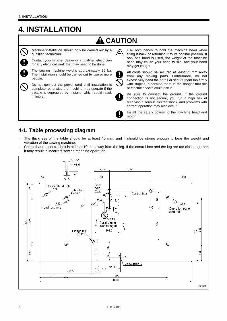
4-1. Table processing diagram ・ The thickness of the table should be at least 40 mm, and it should be strong enough to bear the weight and
vibration of the sewing machine. ・ Check that the control box is at least 10 mm away from the leg. If the control box and the leg are too close together,
it may result in incorrect sewing machine operation.
4938M
HE-800B 4

4. INSTALLATION
4-2. Installing the control box
CAUTION The control box is heavy, so installation should be carried out by two or more people. In addition, take steps to make sure that the control box does not fall down. If this is not done, injury to feet or damage to the control box may result.
Before installing the control box, check that the model plate (a) on the control box is “HX800B” to indicate that it is an HX-control box for HE-800B sewing machines.
Remove the six screws (1), and then remove the control box cover (2). NOTE:
When opening the cover (2), hold it securely so that it does not fall down.
(3) Bolts [4 pcs.] (4) Cushion collars [4 pcs.] (5) Control box (6) Plain washers [4 pcs.] (7) Nuts [4 pcs. ] (8) Nuts [4 pcs. ]
* Tighten the four nuts (7) until the clearance between the base of the table and the top of the box setting plate (9) is 14 mm.
NOTE: Check that the control box (5) is at
least 10 mm away from the leg. If the control box (5) and the leg are too close together, it may result in incorrect sewing machine operation.
Operator Table
10mm or more
Leg
4736M
4735M
HE-800B 5

4. INSTALLATION
4-3. Installing the flange nut Install the four flange nuts (1) to the underside of the work table.
4-4. Installing the bed base 1. Place the bed base (1) on top of the
work table, and insert the four collars (2).
2. Provisionally tighten the four flange nuts (4) onto the four bolts (3), and then position the bed base (1).
3. Install the bed base (1) with the three flat washers (5) and wood screws (6), and then install the two rubber caps (7).
4. Remove the four bolts (3). 5. Set the magnet (8) in the position
shown in the illustration.
4737M
4069M
HE-800B 6

4. INSTALLATION
4-5. Installing the machine head 1. Place the two bed hinges (1) so that
they are level as shown in the illustration at left, and then place the machine head gently on top of the bed base (3) so that the cables (2) do not get clamped. NOTE: ・ The bed base (3) is made from
plastic, so be careful not to hit it with the machine head when placing the machine head on top of it.
・ Make sure that the felt support (4) do not touch the bed base (3).
2. Install the machine head with the
four spring washers (5) and four bolts (6).
4-6. Installing the head rest (1) Head rest NOTE:
Tap the head rest (1) securely into the table hole. If the head rest (1) is not pushed in as far as it will go, the machine head will not be sufficiently stable when it is tilted back.
4738M
4739M
4740M
HE-800B 7

4. INSTALLATION
4-7. Installing the operation panel (1) Operation panel (2) Screws [4 pcs.] (3) Cushions [4 pcs.] 1. Pass the cord of the operation panel
(1) through the table hole. 2. Loosen the two screws (4) at the
side of the control box, open the cord presser plate (5) in the direction of the arrow, and pass the cord through the hole into the box.
NOTE:
Check that the operation panel cord is not being clamped when screwing the operation panel into the table. The cord may become damaged if it is clamped. 4742M
4741M
HE-800B 8
4. INSTALLATION
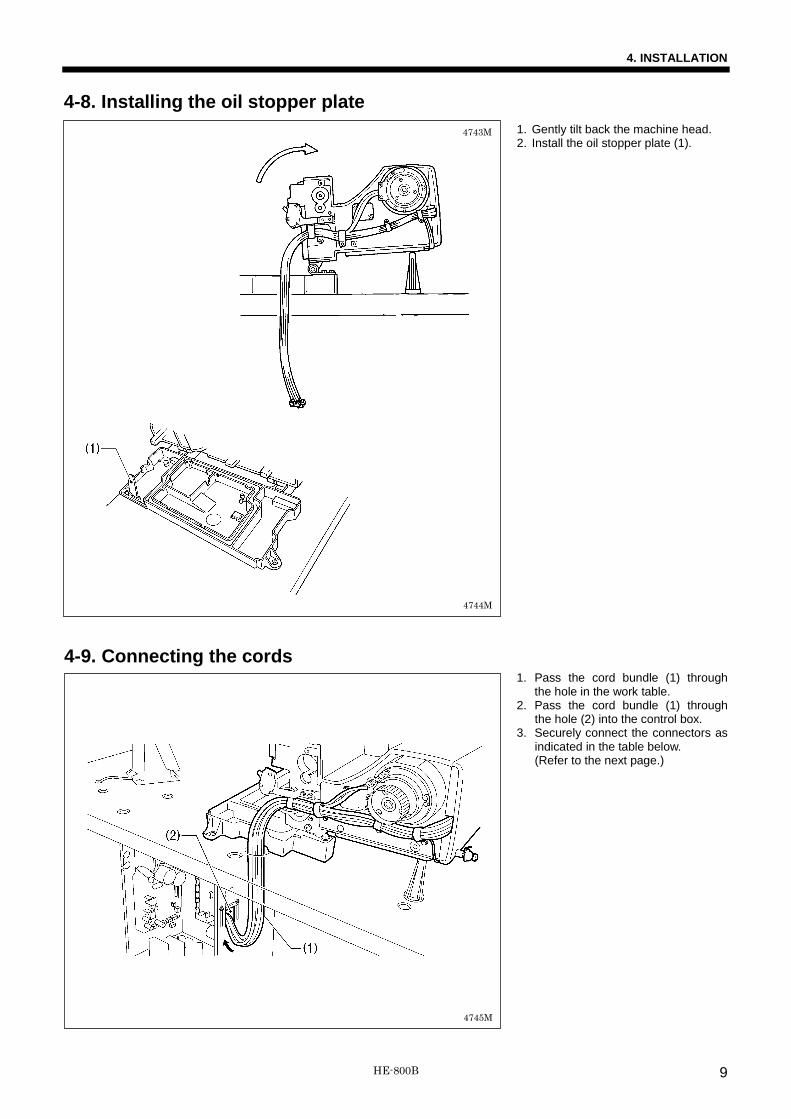
4-8. Installing the oil stopper plate 1. Gently tilt back the machine head. 2. Install the oil stopper plate (1).
4-9. Connecting the cords 1. Pass the cord bundle (1) through
the hole in the work table. 2. Pass the cord bundle (1) through
the hole (2) into the control box. 3. Securely connect the connectors as
indicated in the table below. (Refer to the next page.)
4744M
4743M
4745M
HE-800B 9

4. INSTALLATION
Connector Connection location on main P.C. board Cord clamp
Cutter sensor 6-pin P7 (SENSOR2) (4) (5) Feed sensor, thread breakage sensor 12-pin P8 (SENSOR1) (4) (5) STOP switch 6-pin P9 (HEAD) (4) (5) Safety switch 3-pin P14 (HEAD-SW) (5) Machine head memory 6-pin P16 (HEAD-MEM) (5) Needle zigzag sensor, needle zigzag encoder 5-pin white P17 (X-ENC) (5) Feed encoder 5-pin blue P18 (Y-ENC) (5) Work clamp sensor, work clamp encoder 5-pin black P19 (P-ENC) (5) Needle zigzag motor 4-pin white P21 (XPM) (6) Feed motor 4-pin blue P22 (YPM) (6) Work clamp motor 4-pin black P23 (PPM) (6) Tension release solenoid 4-pin P3 (SOL2) (6)
Connector Connection location on cutter P.C. board Cord clamp
Cutter solenoid 4-pin P2 (SOL) –
NOTE: Route the needle zigzag, feed and work clamp motor harnesses and the tension release solenoid harness so that they do not touch the cutter P.C. board and the power supply P.C. board.
(Continued on next page)
Lock the cord clamp securely.
<Main P.C. board>
<Power supply P.C. board>
<Cutter P.C. board>
4746M
HE-800B 10
4. INSTALLATION
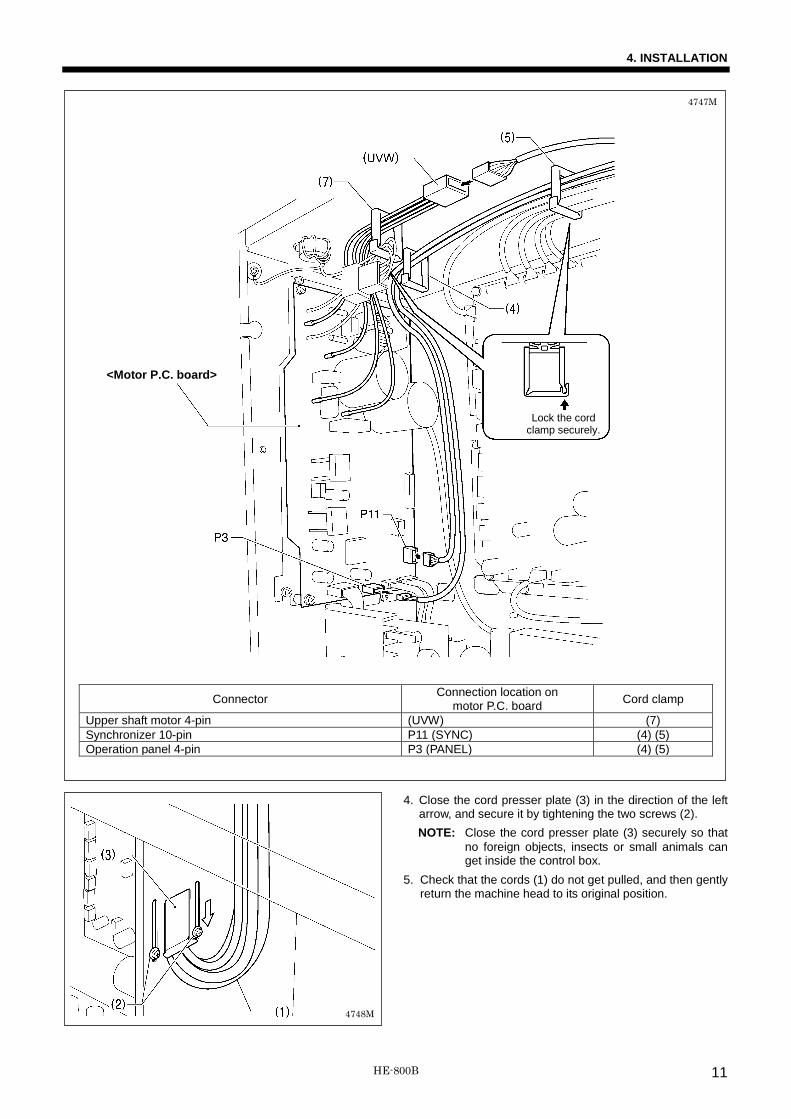
<Motor P.C. board>
Connector Connection location on motor P.C. board Cord clamp
Upper shaft motor 4-pin (UVW) (7) Synchronizer 10-pin P11 (SYNC) (4) (5) Operation panel 4-pin P3 (PANEL) (4) (5)
4. Close the cord presser plate (3) in the direction of the left arrow, and secure it by tightening the two screws (2). NOTE: Close the cord presser plate (3) securely so that
no foreign objects, insects or small animals can get inside the control box.
5. Check that the cords (1) do not get pulled, and then gently return the machine head to its original position.
Lock the cord clamp securely.
4747M
4748M
HE-800B 11

4. INSTALLATION
4-10. Connecting the ground wire
CAUTION Be sure to connect the ground. If the ground connection is not secure, you run the risk of receiving a serious electric shock, and problems with correct operation may also occur.
(1) Ground wire from the machine head (Ground mark position)
* The recommended tightening torque for the ground screws is 1.0±0.1 N・m. NOTE: Make sure that the ground connections are secure in order to ensure safety.
4749M
HE-800B 12

4. INSTALLATION
4-11. Installing the treadle connecting rod (1) Connecting rod (2) Nut
Adjusting the treadle pressure
If the machine starts running when your foot is simply resting on the treadle, or if the treadle pressure is too weak, adjust the position (a to d) at which the treadle spring (3) is hooked onto the treadle lever (4). The treadle pressure will increase from position a to position d.
Adjusting the treadle return pressure
1. Loosen the nut (5) and turn the bolt (6). * The treadle return pressure becomes heavier as the bolt (6) is tightened, and becomes lighter as the bolt (6) is loosened.
2. Tighten the nut (5).
Adjusting the treadle stroke
Remove the nut (2), and then move connecting rod (1) from the position in figure <A> to the position in figure <B>. The treadle stroke will increase by approximately 1.25 times. * This adjustment will also affect the treadle pressure and the treadle return pressure, so these settings should be readjusted
if necessary.
4750M
4752M 4751M
HE-800B 13

4. INSTALLATION
4-12. Installing the cotton stand (1) Cotton stand NOTE:
Securely tighten the nut (4) so that the two rubber cushions (2) and the washer (3) are securely clamped and so that the cotton stand (1) does not move.
4-13. Installing the eye guard
CAUTION
Attach all safety devices before using the sewing machine. If the machine is used without these devices attached, injury may result.
(1) Eye guard assembly (2) Washer (3) Screw
4753M
4754M
HE-800B 14

4. INSTALLATION
4-14. Lubrication
CAUTION
Turn off the power switch before starting lubricating, otherwise the machine may operate if the treadle is depressed by mistake, which could result in injury.
Be sure to wear protective goggles and gloves when handling the lubricating oil and grease, so that they do not get into your eyes or onto your skin, otherwise inflammation can result. Furthermore, do not drink the oil or eat the grease under any circumstances, as they can cause vomiting and diarrhea. Keep the oil out of the reach of children.
Be careful not to get your hands caught when returning the machine head to its original position after it has been tilted.
The sewing machine should always be lubricated and the oil supply replenished before it is used for the first time, and also after long periods of non-use. Use only the lubricating oil <JX Nippon Oil & Energy Corporation Sewing Lube 10N; VG10> specified by Brother. * If this type of lubricating oil is difficult to obtain, the recommended oil to use is <Exxon Mobil Essotex SM10; VG10>.
4-14-1. Lubricating the bed base 1. Gently tilt back the machine head. 2. Slowly pour in lubricating oil until the
oil level reaches the “HIGH” mark. 3. Gently return the machine head to
its original position.
* Periodically tilt back the machine head and check the lubricating oil level. If the oil level drops below the “LOW” mark, add more lubricating oil.
* Replace the lubricating oil about once every six months.
4-14-2. Lubricating the arm Apply 5-6 drops of oil to the oil inlet (1) at the top of the arm. * When using the machine, check that
the oil is visible through the oil window (2). If it cannot be seen, problems such as seizure of the mechanism may occur.
3898Q
4072M
HE-800B 15

4. INSTALLATION
4-14-3. Lubricating the rotary hook When first installing the machine and when the machine has not been used for an extended period of time, remove the bobbin and add 2-3 drops of oil to the rotary hook race (1) before sewing.
Rotary hook lubrication adjustment 1. Remove the rubber cap (2). 2. Turn the adjusting screw (3) to
adjust the lubrication amount. * Adjust so that approximately 10
drops of oil are released when the sewing machine is run at a speed of 4,000 sti/min for three cycles to sew about 114 stitches. Use Kraft paper (4) or similar to catch the oil drops. As a guide, the optimum position can be obtained if the adjusting screw (3) is tightened as much as possible and then loosened about two turns.
4-15. Connecting the power cord
CAUTION Be sure to connect the ground. If the
ground connection is not secure, you run a high risk of receiving a serious electric shock, and problems with correct operation may also occur.
Connect cords that match the voltage specifications. (Refer to the next page.) <EU specifications> (1) Filter box (2) Screws [4 pcs] (3) Staples [7 pcs] (4) Power cord 1. Attach an appropriate plug to the
power cord (4). (The green and yellow wire is the ground wire.)
2. Insert the power plug into a properly-grounded electrical outlet.
NOTE: • Take care when tapping in the staples
(3) to make sure that they do not pierce the cords.
• Do not use extension cords, otherwise machine operation problems may result.
More
Less
< Seen from underneath table >
4935M
Leg
Green and yellow wire (ground wire)
Control box
4755M
4756M
HE-800B 16
4. INSTALLATION
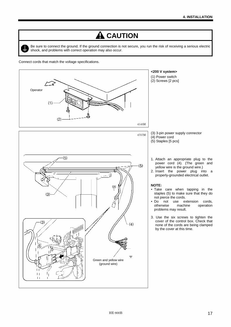
CAUTION Be sure to connect the ground. If the ground connection is not secure, you run the risk of receiving a serious electric shock, and problems with correct operation may also occur.
Connect cords that match the voltage specifications.
<200 V system> (1) Power switch (2) Screws [2 pcs] (3) 3-pin power supply connector (4) Power cord (5) Staples [5 pcs]
1. Attach an appropriate plug to the
power cord (4). (The green and yellow wire is the ground wire.)
2. Insert the power plug into a properly-grounded electrical outlet.
NOTE: • Take care when tapping in the
staples (5) to make sure that they do not pierce the cords.
• Do not use extension cords, otherwise machine operation problems may result.
3. Use the six screws to tighten the
cover of the control box. Check that none of the cords are being clamped by the cover at this time.
Green and yellow wire (ground wire)
Operator
4145M
4757M
HE-800B 17

4. INSTALLATION
<100 V / 400 V system> (1) Power switch (2) Screws [2 pcs] (3) Transformer box (4) Transformer box plates [2 pcs] (5) Screw [with washer] (6) 3-pin power supply connector (7) Staples [6 pcs] (8) Cord clamps [2 pcs] (9) Power cord 1. Attach an appropriate plug to the
power cord (9). (The green and yellow wire is the ground wire.)
2. Insert the power plug into a properly-grounded AC power supply.
* The inside of the control box uses
single-phase power. NOTE: • If the ground connection is not
secure, electric shocks, operating errors or damage to electronic components such as P.C. boards may occur.
• Take care when tapping in the staples (7) to make sure that they do not pierce the cords.
• Do not use extension cords, otherwise machine operation problems may result.
3. Use the six screws to tighten the
cover of the control box. Check that none of the cords are being clamped by the cover at this time.
Green and yellow wire (ground wire)
4145M
4758M
4936M
Operator
HE-800B 18

4. INSTALLATION
4-16. Checking the safety switch 1. Turn on the power switch (1). 2. Check that no error numbers appear
on the operation panel.
<If an error number is displayed> If the safety switch (2) is not turned on, error [E050], [E051] or [E055] will occur. 1) Loosen the two bolts (3), and then
adjust the safety switch (2) to a position where no error is displayed.
2) Tighten the two bolts (3).
3. After checking that no error numbers are displayed, turn off the power switch (1).
4-17. Installing the motor cover 1. Install the motor cover (2) with the
three screws (1) (other than <A>). NOTE:
Be careful not to clamp the cords (3) when installing the motor cover (2).
2. Loosen the knob screw (4), and then fully open the slider cover (5). (Figure <B>) NOTE: ・ If you try to open the slide cover
(5) any further when it is already fully open, the slide cover (5) may become damaged.
・ If the opening angle of the slide cover (5) is too small, the slide cover (5) will close from its own weight or momentum, and your fingers or other objects may get caught. (Figure <C>)
3. Tighten the screw (1) at <A> to secure the motor cover (2).
4. Once the motor cover (2) has been installed, close the slide cover (5) and tighten the knob screw (4) to secure it.
4761M
4760M
4762M
HE-800B 19

4. INSTALLATION
4-18. Installing the auxiliary table 1. Provisionally install the two table
support plates (1) to the auxiliary table (2) with the four bolts (3).
2. Install the auxiliary table (2) to the bed (4) with the two bolts (5).
3. While gently pushing the auxiliary table (2) so that there is no clearance between the bed (4) and the auxiliary table (2), tighten the four bolts (3).
Set so that there is no clearance
4763M
HE-800B 20

5. PREPARATION BEFORE SEWING
5. PREPARATION BEFORE SEWING 5-1. Installing the needle
CAUTION
Turn off the power switch before installing the needle, otherwise the machine may operate if the treadle is depressed by mistake, which could result in injury.
Use a Schmetz Nm 134 needle. 1. Loosen the set screw (1). 2. Insert the needle as far as it will go so that the groove
is facing toward you. 3. Securely tighten the set screw (1). [At the time of shipment]
Spec. -2 -3 Needle 134 Nm90 134 Nm75
Front
Groove
4764M
HE-800B 21

5. PREPARATION BEFORE SEWING
5-2. Threading the upper thread
CAUTION
Use threading mode or turn off the power first in order to carry out threading.
Thread the upper thread correctly as shown in the illustration. ▪ When pulling the thread out from the zigzag thread tension (1), move the tension release lever (2) in the direction of the
arrow to open the tension discs (3) in order to make it easier to pull out the thread. ▪ After threading the arm thread guide (4), pass the thread under the thread guide (5) as shown in the illustration to make it
easier to thread. ▪ Push the needle bar to the right to make it easier to pass the thread through the needle.
* When the sewing machine is threaded in threading mode, the tension discs (3) will be open and the needle will be moved to the right to make it easier to thread the upper thread. (Refer to the next page.)
NOTE: ▪ If you start sewing without passing the thread through the thread guide (5), error “E600” will be generated and the sewing
machine will stop. ▪ The thread tension (6) is used to prevent the upper thread from becoming knotted, tangled or loose, so do not touch it. It is
tightened only gently. If it is tightened too firmly, the knob may become damaged.
For spun thread and cotton thread
For polyester thread
For threads which do not slide easily
Thread will get caught
or
4889M
HE-800B 22

5. PREPARATION BEFORE SEWING
<Threading mode> When the sewing machine is threaded in threading mode, the tension discs will be open and the needle will be moved to the right to make it easier to thread the upper thread. In addition, the sewing machine will not start up threading mode, even if the treadle is depressed.
1 Press the THREAD key while the sewing machine is at standby in automatic sewing mode or test feeding mode.
・ The work clamp will drop. ・ The tension discs will be fully opened. ・ The needle will move to the right.
2 Thread the upper thread.
3 Once threading of the upper thread is complete, press the THREAD key.
・ The work clamp and the needle will return to their original
positions. ・ The tension discs will close.
<Reference>
If you press the ▼ key while in threading mode, the needle will return to the middle position. If you press the ▲ key, the needle will move to the right.
4916M 4767M 4765M
4768M
Flashing
4769M
HE-800B 23

5. PREPARATION BEFORE SEWING
5-3. Winding the lower thread
CAUTION
Do not touch any of the moving parts or press any objects against the machine while winding the lower thread, as this may result in personal injury or damage to the machine.
1. Place the bobbin onto the bobbin winder shaft (1). 2. Thread the thread as shown in the illustration, wind the thread around the bobbin several times, and then press the bobbin
presser (2). 3. Turn on the power switch. 4. Depress the treadle to the 2nd step. (Home position detection will be carried out.) 5. Press the AUTO key (3) to change the mode to automatic sewing mode. 6. While pressing the WIND key (4), depress the treadle to the 2nd step. 7. When the sewing machine starts operating, release the WIND key (4), and keep depressing the treadle until winding of the
lower thread is complete. (Once winding of the set amount of lower thread is complete (80% to 90% of the bobbin diameter), the bobbin presser (2) will return automatically.)
8. When winding of the lower thread is complete, release the treadle. 9. Remove the bobbin, hook the thread onto the knife (5), and then pull the bobbin in the direction of the arrow to cut the
thread.
Adjusting the bobbin winding amount Loosen the screw (6) and move the bobbin presser (2) to adjust. If the thread winds onto the bobbin unevenly Loosen the set screw (7) and move the bobbin wider tension bracket (8) up and down to adjust. * For case A, move the bobbin winder tension bracket
(8) down, and for case B, move it upward.
Case A
Case B
4770M
4891M 4771M
4772M
4892M
HE-800B 24

5. PREPARATION BEFORE SEWING
5-4. Installing the bobbin case
CAUTION
Turn off the power switch before installing the bobbin case. The machine may operate if the treadle is depressed by mistake, which could result in injury.
1. Insert the bobbin into the bobbin case as shown in the illustration.
NOTE: If the bobbin is inserted back to front, the bobbin will spin freely and the work clamp pulse motor will get out of step. 2. Pass the thread though the slot (1) and then under the tension spring (2) and through the slot (3). 3. When sewing whip stitches, pull approximately 40 mm of thread out from the thread hole (4), and when sewing purl
stitches, pull approximately 40 mm of thread out from thread hole (5).
4. Open the rotary hook cover (6). 5. Hold the latch on the bobbin case and insert the
bobbin case into the rotary hook. 6. Close the rotary hook cover (6).
2812Q
Purl stitch (seal stitch)
Whip stitch (plain stitch)
4773M
HE-800B 25

5. PREPARATION BEFORE SEWING
5-5. Thread tension The shapes of the seams for all patterns which have been stored in programs 1 to 50 can be set using parameter No. 53. Make the following adjustments in accordance with the seam shape which has been set.
[Stitch patterns] Whip stitch (plain stitch) The above stitch pattern in which the upper thread moves over the top and the bottom thread moves over the bottom of the material in a zigzag pattern is called a “whip” stitch. This pattern is identical to the zigzag pattern of a lock stitch zigzag machine. Purl stitch (seal stitch) The above pattern in which the upper needle thread tension is high and the upper needle follows a straight line through the seam center while the lower thread moves left to right and intertwines with the upper thread is called a “purl” stitch. [Reference thread tension] Stitch patterns Whip stitch Purl stitch Upper thread Polyester #50 Spun #60 Polyester #50 Spun #60 Lower thread Polyester #50 Spun #60 Polyester #50 Spun #60 Upper thread tension (N) 0.3 - 0.7 0.40 - 0.75 0.75 - 2.00 1.0 - 2.5 Lower thread tension (N) 0.15 - 0.35 0.05 - 0.25 Thread take-up spring tension (mm) 4 - 6 Thread take-up spring height (N) 0.1 - 0.2
5-5-1. Lower thread tension Whip stitch (plain stitch) Adjust by turning the adjusting screw (1) until the bobbin case drops when it is shaken slightly (0.15 - 0.35 N) while the thread end coming out of the bobbin case is held. Purl stitch (seal stitch) Adjust by turning the adjusting screw (1) until the bobbin case drops gently by its own weight (0.05 - 0.25 N) while the thread end coming out of the bobbin case is held.
1229Q 1228Q
Becomes stronger
Becomes weaker
2813Q
Purl stitch (seal stitch) Front Back
Whip stitch (plain stitch) Front Back
HE-800B 26

5. PREPARATION BEFORE SEWING
5-5-2. Upper thread tension
Whip stitch (plain stitch) To ensure that neat seams will be sewn in the bar tacking areas and zigzag areas, adjust the upper thread tension while the zigzag tension discs are open as shown in "[A] When the zigzag tension discs (1) are open” below.
Purl stitch (seal stitch) 1. First, to ensure that neat seams will be sewn in the bar tacking areas, adjust the upper thread tension while the zigzag
tension discs are open as shown in "[A] When the zigzag tension discs (1) are open” below. 2. Next, to ensure that neat seams will be sewn in the purl areas, adjust the upper thread tension while the zigzag tension
discs are closed as shown in "[B] When the zigzag tension discs (1) are closed” below.
Adjustment method Use threading mode to adjust by the procedure given below. In addition, the procedure is safe because the sewing machine will not start up, even if the treadle is depressed. [A] When the zigzag tension discs (1) are open 1. Press the THREAD key.
(The sewing machine will switch to threading mode. The zigzag tension discs (1) will be fully opened.)
2. Turn the tack tension control (2) to adjust the tension for the bar tacking area and the zigzag area.
3. Measure the upper thread tension as shown in the illustration.
4. Press the THREAD key to exit threading mode. [B] When the zigzag tension discs (1) are closed 1. Press the THREAD key.
(The sewing machine will switch to threading mode.) 2. Press the ▼ key.
(The zigzag tension discs (1) will be fully closed.) 3. Turn the zigzag tension control (3) to adjust the
tension for the purl area. 4. Measure the upper thread tension as shown in the
illustration. 5. Press the THREAD key to exit threading mode.
[A] Zigzag areas
[A] Bar tacking areas
Whip stitch (plain stitch) Purl stitch (seal stitch)
[A] Bar tacking areas
[B] Purl areas
4775M 4774M
Open
4776M
Closed
HE-800B 27

5. PREPARATION BEFORE SEWING
5-5-3. Thread take-up spring height Loosen the set screw (1), and turn the entire thread tension adjuster to adjust the thread take-up spring height to between 4 - 6 mm in accordance with the material to be sewn.
5-5-4. Thread take-up spring tension Turn the thread tension stud (1) to adjust the thread take-up spring tension to between approximately 0.1 - 0.2 N in accordance with the material to be sewn.
5-5-5. Adjusting arm thread guide The standard position of arm thread guide (1) is when the screw (2) is aligned with the index mark. The standard position for the arm thread guide (3) is when the clearance between it and the screw (4) is 0.5 mm as shown in the illustration.
3958Q
Weaker
Stronger
3960Q
Index mark
0.5mm
4777M
HE-800B 28

6. USING THE SEWING MACHINE (OPERATION PANEL: BASIC OPERATION)
6. USING THE SEWING MACHINE (OPERATION PANEL: BASIC OPERATION)
6-1. Name and function of each operation panel item
(1) Power indicator Illuminates when the power is turned on.
(2) Display This shows information such as program numbers and messages.
(3) CAUTION indicator Flashes when displaying an error which can be reset, and illuminates when displaying an error which cannot be reset.
(4) RESET key This key is used to reset errors and to reset the production counter value.
(5) key This key is used to decrease the values for program numbers and parameter numbers.
(6) key This key is used to increase the values for program numbers and parameter numbers.
(7) key This key is used to decrease the values for parameter settings and memory switch settings.
(8) key This key is used to increase the values for parameter settings and memory switch settings.
(9) ENTER key This key is used to apply the values for parameter settings and memory switch settings.
(10) Shortcut 1 key This key is used to change the “Sewing speed (zigzag part)” setting.
(11) Shortcut 2 key This key is used to change the “Length of the hole” setting.
(12) Shortcut 3 key This key is used to change the “Zigzag pitch” setting.
(13) Shortcut 4 key This key is used to change the “Zigzag width” setting.
(14) Shortcut 5 key This key is used to change the “Cutter X space” setting.
(15) Shortcut 6 key This key is used to change the “No. of rectangle underlays” setting.
(Continued on next page)
4778M
HE-800B 29
6. USING THE SEWING MACHINE (OPERATION PANEL: BASIC OPERATION)
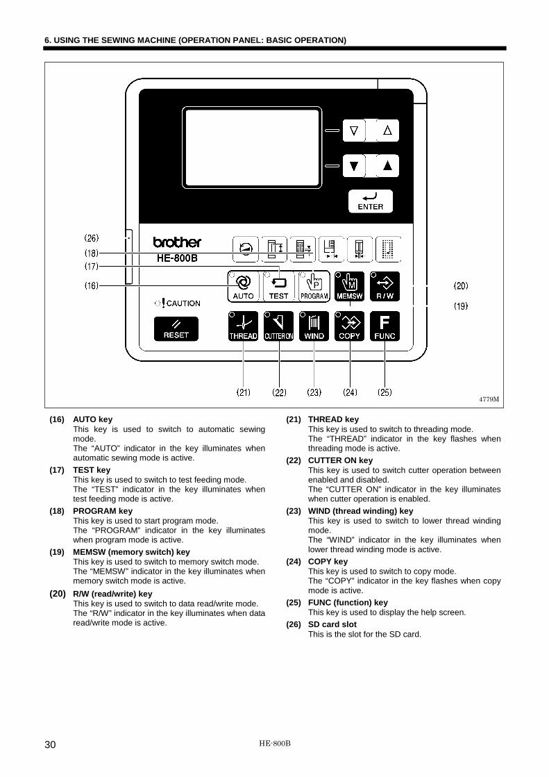
(16) AUTO key This key is used to switch to automatic sewing mode. The “AUTO” indicator in the key illuminates when automatic sewing mode is active.
(17) TEST key This key is used to switch to test feeding mode. The “TEST” indicator in the key illuminates when test feeding mode is active.
(18) PROGRAM key This key is used to start program mode. The “PROGRAM” indicator in the key illuminates when program mode is active.
(19) MEMSW (memory switch) key This key is used to switch to memory switch mode. The “MEMSW” indicator in the key illuminates when memory switch mode is active.
(20) R/W (read/write) key This key is used to switch to data read/write mode. The “R/W” indicator in the key illuminates when data read/write mode is active.
(21) THREAD key This key is used to switch to threading mode. The “THREAD” indicator in the key flashes when threading mode is active.
(22) CUTTER ON key This key is used to switch cutter operation between enabled and disabled. The “CUTTER ON” indicator in the key illuminates when cutter operation is enabled.
(23) WIND (thread winding) key This key is used to switch to lower thread winding mode. The “WIND” indicator in the key illuminates when lower thread winding mode is active.
(24) COPY key This key is used to switch to copy mode. The “COPY” indicator in the key flashes when copy mode is active.
(25) FUNC (function) key This key is used to display the help screen.
(26) SD card slot This is the slot for the SD card.
4779M
HE-800B 30

6. USING THE SEWING MACHINE (OPERATION PANEL: BASIC OPERATION)
6-2. Starting the sewing machine
1 Push the power switch (1) to the ON side. The power indicator (2) will illuminate and the contents of the panel display (3) will switch in the order shown below.
2 Depress the treadle (4).
・ The needle bar and the work clamp will move to the home position.
・ The operation panel display will show the standby condition*1 for the mode that was active when operation last stopped (if it was automatic sewing mode, test feeding mode or program mode).
*1: The “standby condition” is the name for the period from the point after switching to one of these modes until the first operation occurs.
Displayed for approx. 2 second Sewing area
4781M
4782M
4917M 4780M
4784M
HE-800B 31

6. USING THE SEWING MACHINE (OPERATION PANEL: BASIC OPERATION)
6-3. Operating the treadle
1. When the treadle is not depressed (A), the work clamp is at the neutral position. (Figure [1]) 2. When the treadle is depressed to the 1st step (B), the work clamp will drop. (Figure [2])
When the treadle is released, the work clamp will return to the neutral position. (Figure [1]) 3. When the treadle is depressed to the 2nd step (C), the machine starts sewing. (Figure [3]) 4. When the treadle is depressed backward to the backward position (D), the work clamp will lift up to higher than the neutral
position. (Figure [4]) This is useful for inserting and removing the material. * The work clamp rises while the treadle is being depressed backward, and it returns to the neutral position when the
treadle is released.
Depressed backward position
(Insertion and removal of the material)
Neutral position Treadle 1st step
(when positioning the material)
[1]
After sewing
[2] [3] [4]
Treadle 2nd step (when starting)
<Work clamp>
<Treadle>
3906Q
HE-800B 32

6. USING THE SEWING MACHINE (OPERATION PANEL: BASIC OPERATION)
6-4. Program setting method It is recommended that you register patterns that are sewn frequently as programs. After programs have been registered, you can retrieve the desired sewing patterns simply by selecting a program number, which eliminates the need to set the pattern each time. • Normally up to 50 programs can be registered, and their contents can be changed at any time. The contents can be set by
changing the parameters for each item. • At the time of shipment from the factory, temporary contents are set for programs P01 to P50. (The contents are the same
for all programs from P01 to P50.) Follow the method given below to change the contents of a program before using it.
1 Switch the mode to test feeding mode.
2 Select the program number from P01 to P50 (1) to select the program that you would like to change.
The program No. (1) changes in the order shown in the illustration each time the key is pressed. (The key changes the order in the opposite direction.) NOTE:
Program mode is not available if a cycle program has been selected.
3 Switch to program mode.
The parameter number (2) that was last selected and the setting (3) for that parameter will appear in the display. * You can also start program mode by pressing a shortcut key. In
this case, the parameter number that corresponds to the shortcut key will be selected. (Refer to the next page.)
Independent program
Cycle program (Refer to the instruction manual CD)
4786M
4918M
4785M
4787M
4789M
4788M
HE-800B 33

6. USING THE SEWING MACHINE (OPERATION PANEL: BASIC OPERATION)
4 Select the parameter number (2) for the parameter that you would like to change. (Refer to “6-4-1. Parameter list”.)
5 Change the setting (3) for the parameter.
Flashing
* The flashing display means that the setting has not yet been applied.
* You can make the initial setting appear in the display by pressing the RESET key.
6 Apply the changed setting.
Illuminates
* The display will change from flashing to illuminated, and this means that the setting has been applied.
* You can cancel the setting change by pressing the , , AUTO, TEST, MEMSW, R/W or COPY key without pressing the ENTER key.
7 Repeat steps 4 - 6 above to change other parameters.
Shortcut keys
The shortcut keys have the following six often-used parameters registered into them.
・ You can retrieve a desired parameter simply by pressing the corresponding shortcut key.
・ Parameters cannot be retrieved if a cycle program has been selected.
(4) Zigzag area sewing speed (Parameter No.15) (5) Length of the hole (Parameter No.02) (6) Zigzag pitch (Parameter No.07) (7) Zigzag width (Parameter No.08) (8) Cutter X space (Parameter No.04) (9) No. of rectangle underlays (Parameter No.42)
4919M
4920M
4934M
4792M
4794M
4795M
4787M
HE-800B 34
6. USING THE SEWING MACHINE (OPERATION PANEL: BASIC OPERATION)
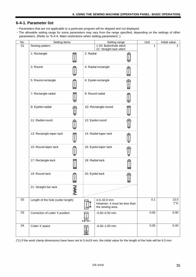
6-4-1. Parameter list ・Parameters that are not applicable to a particular program will be skipped and not displayed. ・The allowable setting range for some parameters may vary from the range specified, depending on the settings of other
parameters. (Refer to “6-4-4. Main restrictions when setting parameters”.)
No. Setting items Setting range Unit Initial value 01 Sewing pattern 1-20: Buttonhole stitch
21: Straight tack stitch 1 1
1: Rectangle
2: Radial
3: Round
4: Radial-rectangle
5: Round-rectangle
6: Eyelet-rectangle
7: Rectangle-radial
8: Round-radial
9: Eyelet-radial
10: Rectangle-round
11: Radial-round
12: Eyelet-round
13: Rectangle-taper tack
14: Radial-taper tack
15: Round-taper tack
16: Eyelet-taper tack
17: Rectangle-tack
18: Radial-tack
19: Round-tack
20: Eyelet-tack
21: Straight bar tack
02 Length of the hole (cutter length) 4.0–32.0 mm However, it must be less than the sewing area.
0.1 13.0 (*1)
03 Correction of cutter X position -0.50–0.50 mm 0.05 0.00
04 Cutter X space
-0.40–1.00 mm 0.05 0.40
(*1) If the work clamp dimensions have been set to 5.4x19 mm, the initial value for the length of the hole will be 6.0 mm.
HE-800B 35

6. USING THE SEWING MACHINE (OPERATION PANEL: BASIC OPERATION)
No. Setting items Setting range Unit Initial value 05 Cutter Y space
0.000–2.000 mm 0.025 1.000
06 Cutter operation (*2)
1: Cutting during sewing Operates when the front tack of the last cycle is sewn (standard)
2: Cutting after sewing Operates when sewing is finished and material is feeding.
3: Cutting before sewing Operates immediately before the left zigzag stitch of the last cycle is sewn.
4: Cutting before sewing + Cutting during sewing
Operates twice: immediately before the left zigzag stitch of the last cycle is sewn and when the front tack of the last cycle is sewn
However, 3 and 4 are only valid for two cycles or more.
1 1
07 Zigzag pitch
0.20–2.50 mm 0.05 0.35
08 Zigzag width
1.00–3.00 mm 0.05 1.50
09 Zigzag width ratio (at left) (*3)
30–70% 1 50
10 Slow start (*4)
Sewing speed for 1st stitch 500–4,000 sti/min 100 500 11 Sewing speed for 2nd stitch 500–4,000 sti/min 100 500 12 Sewing speed for 3rd stitch 500–4,000 sti/min 100 1,200 13 Sewing speed for 4th stitch 500–4,000 sti/min 100 3,000 14 Underlay speed (*5)
500–4,000 sti/min 100 2,000
15 Sewing speed (zigzag part)
1,000–4,000 sti/min 100 3,600
16 Rear tack speed (*5)
500–4,000 sti/min 100 4,000
17 Front tack speed (*5)
500–4,000 sti/min 100 4,000
(*2) Cutting before sewing is enabled only when underlays or 2-cycle sewing exist. In other cases, cutting during sewing will be enabled.
(*3) The zigzag width ratio will be 50% regardless of the setting value for eyelet types. (*4) If underlays exist and the setting speed exceeds the underlay speed, the speed during sewing will equal the underlay
speed. If underlays do not exist and the setting speed exceeds the sewing speed (zigzag part), the speed during sewing will equal the sewing speed (zigzag part).
(*5) If the setting speed exceeds the sewing speed (zigzag part), the speed during sewing will equal the sewing speed (zigzag part).
1: 2: 3: 4:
HE-800B 36

6. USING THE SEWING MACHINE (OPERATION PANEL: BASIC OPERATION)
No. Setting items Setting range Unit Initial value 18 Front tack length
(except taper tack)
0.5–5.0 mm 0.1 1.0
19 Front tack pitch (except radial)
0.10–1.00 mm 0.05 0.30
20 Front tack width correction
(except radial)
-2.0–2.0 mm 0.1 0.0
21 No. of front tack stitch (radial only)
5–11 stitches 2 7
22 Taper tack length (taper tack only)
1.0–5.0 mm 0.1 3.0
23 Front tack sideways correction (rectangle only)
-1.0–1.0 mm 0.1 0.0
25 Rear tack length (except eyelet)
0.5–5.0 mm 0.1 1.0
26 Rear tack pitch
(except radial, eyelet)
0.10–1.00 mm 0.05 0.30
27 Rear tack width correction (except radial, eyelet)
-2.0–2.0 mm 0.1 0.0
28 No. of rear tack stitch (radial, eyelet only)
5–11 stitches 2 7
4796M 4797M 4798M 4799M 4800M
HE-800B 37

6. USING THE SEWING MACHINE (OPERATION PANEL: BASIC OPERATION)
No. Setting items Setting range Unit Initial value 29 Eyelet buttonhole radius
(eyelet type only)
1.0–3.0 mm 0.1 2.0
30 Rear tack sideways correction (rectangle only)
-1.0–1.0 mm 0.1 0.0
31 Rear tack vector shape (rectangle only)
1: Triangle 2: Rectangle 3: Saw-shape
1 1
34 Straight bar tack length
7.0–40.0 mm 0.1 13.0
35 Straight bar tack pitch
0.2–2.0 mm 0.1 0.8
36 Straight bar tack width
1.5–6.0 mm 0.1 2.0
38 Start backtack
0–6 stitches 2 2
39 Start backtack width
0.5–3.0 mm 0.1 0.5
40 Start backtack pitch
0.10–0.80 mm 0.05 0.30
41 No. of sewn-together underlays (*6)
0–1 times 1 0
42 No. of rectangle underlays
0–9 times 1 0
43 Saw-shaped underlays
OFF: No saw-shaped underlays 1: Front and rear tack 2: Rear tack only 3: Front tack only
1 OFF
(*6) If sewn-together underlays and rectangle underlays have been set at the same time, rectangle underlays will be sewn after sewn-together underlays have been sewn.
1: 2: 3:
1:
2:
3:
HE-800B 38

6. USING THE SEWING MACHINE (OPERATION PANEL: BASIC OPERATION)
No. Setting items Setting range Unit Initial value 44 Underlay offset
0.30–1.00 mm 0.05 0.80
45 Underlay sewing start length
2.0–10.0 mm 0.1 4.0
46 Underlay zigzag width for first cycle
0.0–3.0 mm 0.1 0.0
47 Underlay feed pitch (including for sewn-together underlays)
1.0–6.0 mm 0.1 2.0
48 Type of 2-cycle sewing
OFF: No double stitch 1: Identical double stitch 2: Crossed double stitch
1 OFF
49 No. of bar tacks sewn for 2-cycle sewing
1–2 times
1 2
50 First offset for 2-cycle sewing
0.0–0.8 mm 0.1 0.3
51 End backtack
1–6 stitches 1 4
52 End tacktack width (rectangle only)
OFF: Condense stitch 0.1–1.5 mm (Normally set to 1.0.)
0.1 OFF
OFF: Condense stitch 0.1–1.5 mm
(Continued on next page)
1: 2:
4801M
HE-800B 39

6. USING THE SEWING MACHINE (OPERATION PANEL: BASIC OPERATION)
No. Setting items Setting range Unit Initial value 53 Stitch type (Whip/Purl)
1–16
1 -2 specifications: 2 -3 specifications: 1
1:
2:
3:
4:
5:
6: 7: 8:
9:
10: 11: 12:
13:
14: 15: 16:
54 Tension apply timing A (Left zigzag stitch)
-4–6 stitches 1 0
55 Tension release timing B (Rear tack)
-4–4 stitches 1 0
56 Tension apply timing C (Right zigzag stitch)
-4–4 stitches 1 0
57 Tension release timing D (Front tack)
-4–4 stitches 1 0
58 Sewing end tension apply timing
-5–0 stitches 1 0
Whip Purl
3919Q
Rear tack
Right zigzag stitch Left zigzag stitch
Front tack
HE-800B 40

6. USING THE SEWING MACHINE (OPERATION PANEL: BASIC OPERATION)
6-4-2. Setting the length of the hole Set parameter number 02 to the length of the hole that matches the cutter being used. Be sure to change the setting for the length of the hole if the cutter is replaced with a cutter of a different length. The stitch length will be automatically determined by the value for the length of the hole which has been set. Therefore, if the length is not set correctly, problems may occur, such as the bar tacking areas being cut by the cutter.
6-4-3. Buttonhole sewing size A. Length of the hole (Parameter No.02) B. Zigzag width (Parameter No.08) C. Cutter X space (Parameter No.04) D. Cutter Y space (Parameter No.05) E. Front tack length (Parameter No.18) F. Rear tack length (Parameter No.25) G. Zigzag stitch length (A + D + D) * H. Bar tack width (B + B + C) * I. Buttonhole length (A + D + D + E + F) * * Set automatically.
6-4-4. Main restrictions when setting parameters
When the sewing area is set to 4.0 x 32.0 mm (default setting) Symptom Cause
Parameter number 08 (Zigzag width) does not become larger.
If the sewing area is 4.0 mm and parameter number 04 (Cutter X space) is set to 0.2 mm, the zigzag width that can be entered will be limited to (4.0 - 0.2) ÷ 2 = 1.9 mm.
Parameter number 04 (Cutter X space) does not become larger.
If the sewing area is 4.0 mm and parameter number 08 (Zigzag width) is set to 1.8 mm, the cutter X space that can be entered will be limited to 4.0 - (1.8 + 1.8) = 0.4 mm.
Parameter number 29 (Eyelet buttonhole radius) does not become larger or smaller.
If the sewing area is 4.0 mm and parameter number 04 (Cutter X space) is set to 0.2 mm and parameter number 08 (Zigzag width) is set to 1.5 mm, the eyelet buttonhole radius that can be entered will be a minimum of (1.5 + 1.5 + 0.2) ÷ 2 = 1.6 mm, and a maximum of 4.0 ÷ 2 = 2.0 mm.
(Continued on next page)
3922Q
4802M
4803M
HE-800B 41

6. USING THE SEWING MACHINE (OPERATION PANEL: BASIC OPERATION)
Symptom Cause
Parameter number 02 (Length of the hole) does not become larger.
If the sewing area is 32.0 mm and parameter number 05 (Cutter Y space) is set to 1.0 mm, parameter number 18 (Front tack length) is set to 1.0 mm and parameter number 25 (Rear tack length) is set to 1.0 mm, the length of the hole will be 32.0 - 1.0 - 1.0 - 1.0 - 1.0 = 28.0 mm. (The default setting is 27.8 mm to match the positions of the needle and cutter.)
Parameter number 05 (Cutter Y space) does not become larger.
See illustration.
Parameter number 18 (Front tack length) and parameter number 25 (Rear tack length) do not become larger.
See illustration.
6-5. Rear tack vector shape programs Parameter No. 31
1: Triangle 2: Rectangle 3: Saw-shape
Setting range 1: Triangle General sewing Setting range 2: Rectangle ▪ This is effective for preventing the material from getting stuck in the needle hole when sewing the rear tack, which can
happen when using lightweight materials. (An offset is used so that the stitches do not overlap when sewing the reverse zigzagging for the rear tack.)
▪ Reducing the number of front tack stitches is effective in preventing the material getting stuck at the front tack. ▪ Using a needle plate with a small needle hole (1.2 mm) as well can also help in preventing the material from getting stuck. Setting range 3: Saw-shape This is effective for preventing dimples in the rear tack, without the need for underlay sewing.
4806M 4805M 4807M
4804M
HE-800B 42

6. USING THE SEWING MACHINE (OPERATION PANEL: BASIC OPERATION)
6-6. Underlay programs Four types of underlay patterns are available. These four types can also be combined. Refer to the examples of use to determine which type of underlay to use.
Parameter No. 41 43 42 46
Sewn-together underlays Saw-shape underlays Rectangle underlays Underlay zigzag width
Sewn-together underlays ▪ This type of underlay pattern is used for resewing if the cutter has operated before the seam has been formed, such as
when sewing is complete without the upper thread breaking even though the lower thread has run out. It is particularly useful for sewing up the hole made by the cutter beforehand at times when zigzag stitches do not hold properly.
▪ The pile of fluffy fabrics is pressed down before sewing, so that the buttonhole finish looks more attractive. Saw-shape underlays ▪ This type of underlay is useful for stretch materials to prevent them from stretching. ▪ It is useful for preventing dimples from forming during bar tacking. Radial-type buttonholes are useful for preventing
dimples. ▪ It is also useful for strengthening the buttonholes to stop the seam from unravelling, which can often happen with
materials with coarse weaves. Rectangle underlays ▪ This type of underlay is useful for stretch materials to prevent them from stretching. ▪ This is effective in preventing seams from unravelling in materials which appear not to have a very coarse weave. It also
serves to reinforce the buttonhole. ▪ If the seam is hidden and the seam width seems small, you can sew 2 - 3 rectangle underlays to make the material look
more voluminous. ▪ Underlays such as (1) to (9) in the illustration can be sewn in slightly different positions by changing the setting value for
parameter No. 44 (underlay offset) so that the seam does not become too stiff and to further increase the feeling of volume.
Underlay zigzag width
If parameter No. 46 (underlay zigzag width for first cycle) is set after saw-shaped underlays or rectangle underlays have been set, zigzag underlays will only be sewn for the first cycle of saw-shaped underlays or rectangle underlays. ▪ This is particularly effective in preventing seams from unravelling in materials which appear not to have a very coarse
weave. It also serves to reinforce the buttonhole. ▪ If parameter No. 46 (underlay zigzag width for first cycle) [Dimension A in the illustration] is set to about 0.4 mm, the
zigzag underlay stitches will be even less likely to unravel than other underlay stitches.
NOTE: ▪ When sewing underlays, the number of bar tacking stitches will increase, so that thread breakages or broken needles may
occur. Reduce the number of underlays, or use shortcut key 1 or parameter No. 15 to reduce the sewing speed (zigzag part).
▪ When underlays above are sewn together, the order of sewing is sewn-together underlays → saw-shape underlays → rectangle underlays.
3933Q 3932Q 3934Q 3931Q
HE-800B 43

6. USING THE SEWING MACHINE (OPERATION PANEL: BASIC OPERATION)
6-7. Cutter operation The cutter operating pattern can be selected from the following four patterns.
Parameter No. 06
1: Cutting during sewing 2: Cutting after sewing 3: Cutting before sewing 4: Cutting before sewing + Cutting during sewing
Operates when the front tack of the last buttonhole cycle is sewn.
Operates near the front tack when sewing is finished and material is feeding.
Operates immediately before the left zigzag stitch of the last cycle is sewn.
Operates twice: immediately before the left zigzag stitch of the last cycle is sewn and when the front tack of the last cycle is sewn.
Setting range 1: Cutting during sewing General sewing Setting range 2: Cutting after sewing
Because the needle and cutter positions are separated by 2.2 mm as shown in the illustration, the distance between the edge of the front tack and the edge of the buttonhole cannot be set to less than 2.2 mm. For example, if the cutter Y space (A) is set to 0.5 mm, the front tack length (B) will not go below 1.7 mm. At such times, the front tack length can be set to less than 1.7 mm when using cutting after sewing. Once sewing is finished and material feeding has finished, the cutter will operate.
Setting range 3: Cutting before sewing ▪ Does not operate during the first sewing cycle. Only applies to second and subsequent cycles (during underlay sewing and
overlap sewing). ▪ This is used in cases such as when the rough edges of the material after cutting are hemmed by the buttonhole stitches. ▪ The cutter operates before the left zigzag stitch of the last cycle is sewn. Setting range 4: Cutting before sewing + Cutting during sewing ▪ Does not operate during the first sewing cycle. Only applies to second and subsequent cycles (during underlay sewing and
overlap sewing). ▪ This is used in cases such as when the rough edges of the material after cutting are hemmed by the buttonhole stitches. ▪ It can also be used if the rough edges of the material block the buttonhole after the left and right zigzag stitches have been
sewn. ▪ The cutter operates immediately before the left zigzag stitch of the last cycle is sewn, and it operates again when the front
tack of the last cycle is sewn.
3937Q 3936Q 3938Q 3935Q
3939Q 2.2 mm
Feeding
HE-800B 44

6. USING THE SEWING MACHINE (OPERATION PANEL: BASIC OPERATION)
6-8. Copying programs To create a program with parameters that are almost exactly the same as those of another program, you can copy the original program and change just the parts which need to be changed.
1 Press any one of the following keys. (Any one of these keys can be pressed.)
2 Press the COPY key. (The sewing machine will switch to program copy mode.)
The program number for the copying source (1) and the program number for the copying destination (2) before entering this mode will appear in the display.
3 Select the program number for the copying source (1).
・ The program number for the copying source (1) changes in the
order shown in the illustration each time the key is pressed.(The key changes the order in the opposite direction.)
・ The program number for the copying source (1) and the program number for the copying destination (2) must both be program numbers for the same types of programs.
Independent program: P01~P50 Cycle program: C1~C9
4 Select the program number for the copying destination (2).
The program number for the copying source (1) and the program number for the copying destination (2) must both be program numbers for the same types of programs.
Independent program
Cycle program
Flashing
4810M
4808M
4787M
4809M
4811M
4812M 4792M
Flashing
Flashing
HE-800B 45
6. USING THE SEWING MACHINE (OPERATION PANEL: BASIC OPERATION)
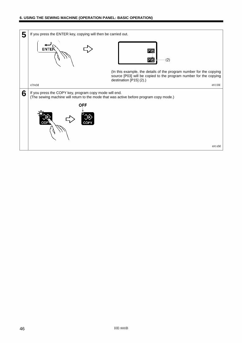
5 If you press the ENTER key, copying will then be carried out.
(In this example, the details of the program number for the copying source [P03] will be copied to the program number for the copying destination [P15] (2).)
6 If you press the COPY key, program copy mode will end. (The sewing machine will return to the mode that was active before program copy mode.)
4794M
4814M
4813M
HE-800B 46

7. USING THE SEWING MACHINE (SEWING OPERATION)
7. USING THE SEWING MACHINE (SEWING OPERATION) CAUTION
Turn off the power switch at the following times, otherwise the machine may operate if the treadle is depressed by mistake, which could result in injury. ▪ When replacing the bobbin and needle ▪ When not using the machine and when leaving the machine unattended
Use threading mode or turn off the power first in order to carry out threading. Do not touch any of the moving parts or press any objects against the machine while sewing, as this may result in personal injury or damage to the machine.
When holding the material, place your right hand at the back and your left hand at the front. If your left hand is toward the back, it may get caught in the feed arm when it operates or it might touch the moving parts of the needle trimmer and injury may result.
NOTE: • The feed arm (1) can move, so be careful of the clearance. • When using the machine, check that the oil is visible through
the oil cap. If it cannot be seen, stop the machine and eliminate the cause of the problem.
7-1. Automatic sewing (Automatic sewing mode) • When carrying out automatic sewing for the first time, be sure to carry out a test sewing first. • In addition, if using the sewing machine when the ambient temperature is cold, carry out several test sewing operations to
allow the motor to warm up.
1 Switch the mode to automatic sewing mode.
Information such as the sewing pattern (1), the program number (2), the cutter operation (3) and the lower thread counter (4) will appear in the display.
2 Select the desired program number (2).
The program number (2) changes in the order shown in the illustration each time the key is pressed. (The key changes the order in the opposite direction.)
Independent program (Refer to P. 33)
4893M
4817M
4816M 4815M
4787M
Cycle program (Refer to the instruction manual CD)
HE-800B 47

7. USING THE SEWING MACHINE (SEWING OPERATION)
3 Place the material under the work clamp, and then depress the treadle (5) to the 1st step (B).
The work clamp will drop.
4 Depress the treadle (5) to the 2nd step (C).
Sewing will then start. * When sewing is complete, the work clamp will
rise.
5 To repeat the sewing operation, repeat steps 3 and 4 above.
7-2. Test feeding mode This mode lets you check needle zigzag, work clamp and length feed plate movement in the sewing pattern which has been programmed without actually sewing the program. (The needle will not move up and down and the cutter will not operate either.)
1 Switch the mode to test feeding mode.
The sewing pattern (1), the program number (2) and the number of stitches (3) will appear in the display.
2 Select the program number (2) for test feeding.
The program number (2) changes in the order shown in the illustration each time the key is pressed. (The key changes the order in the opposite direction.)
4818M
4819M
4821M
4820M
4785M
4787M
Independent program (Refer to P. 33)
Cycle program (Refer to the instruction manual CD)
HE-800B 48

7. USING THE SEWING MACHINE (SEWING OPERATION)
3 Depress the treadle to the 2nd step (C).
The work clamp will drop, and test feeding will start. * However, if the sewing data is protruding outside the sewing
area, “OVER SEW AREA” will be displayed for 1.5 seconds, and test feeding will not be carried out.
4 Test feeding in progress
・ When the treadle is returned to the neutral position, test feeding will be interrupted.
・ If the treadle is depressed to the 2nd step (C), test feeding operation will move forward.
・ Test feeding operation moves forward by one stitch each time the key is pressed. (The key changes operation to the opposite direction.)
・ When the cutter operating position is reached, the buzzer will sound and the cutter icon will be displayed for one second.
* If you press the AUTO key, test feeding mode will be exited and the sewing machine will switch to the automatic sewing standby condition.
<Manual sewing method> Turn the pulley (4) by hand in the direction of the arrow during test feeding. ・ Feeding will move forward by one stitch for each
rotation of the pulley (4). ・ Test feeding operation by turning the pulley (4) by
hand also moves the needle up and down, so if material has been set and the sewing machine is threaded with thread, manual sewing can be carried out.
5 Test feeding complete When the number of stitches remaining reaches “0”, depress the treadle to the 2nd step (C).
・ The above message will be displayed for 1.5 seconds. ・ The work clamp will rise, and test feeding mode will be exited.
NOTE: If you press the RESET key during test feeding or after test feeding is complete, the needle bar and the work clamp will carry out home position detection, and then they will return to the sewing start position.
Number of stitches remaining
4824M
4822M
4825M
4822M 4921M
4823M
HE-800B 49

7. USING THE SEWING MACHINE (SEWING OPERATION)
7-3. Using the STOP switch 7-3-1. Pausing sewing during automatic sewing
The STOP switch is used to stop the sewing machine if a problem occurs such as a thread breakage. <Pausing sewing>
Press the STOP switch (1) while sewing is being carried out.
The sewing machine will stop and the buzzer will sound.
<Clearing the pause (when not continuing from the point where sewing was paused)>
1 Press the RESET key.
(The display will change alternately.)
The buzzer will stop sounding.
2 Eliminate the cause of the problem.
3 Press the RESET key once more.
The needle bar and the work clamp will carry out home position detection, and then they will return to the sewing start position.
4830M 4829M
4831M
4922M 4827M
Flashing
Off
HE-800B 50

7. USING THE SEWING MACHINE (SEWING OPERATION)
<Clearing the pause (when continuing from the point where sewing was paused)>
1 Press the RESET key.
(The display will change alternately.) The buzzer will stop sounding.
2 Eliminate the cause of the problem.
3 Press the key once.
4 Press the and keys to determine the position to resume sewing. • The key moves forward, and the key moves backward. • The feed will move quicker if you keep the key pressed down.
5 Depress the treadle (1) to the 2nd step (C).
Automatic sewing will resume.
NOTE:
If the STOP switch is pressed before the upper shaft motor starts operating or after it has stopped, it will not be possible to continue sewing from the point where sewing was paused.
Off
4832M 4833M
4834M
4835M
4829M 4830M
HE-800B 51

8. TABLE OF ERROR CODES
8. TABLE OF ERROR CODES DANGER
Wait at least 5 minutes after turning off the power switch and disconnecting the power cord from the wall outlet before opening the control box cover. Touching areas where high voltages are present will result in serious injury from electric shocks.
If a problem should occur with the sewing machine, the buzzer will sound and an error code and error message will appear in the display. Follow the remedy procedure to eliminate the cause of the problem. Switch-related errors Items with a “*” in the “Page” column should only be handled by a qualified technician.
Code Cause Remedy Page
E010 Stop switch was pressed during standby. Remove your finger from the stop switch (so that it is off). 1
E011 Stop switch was pressed during sewing.
Press the RESET key to clear the error. * Press the key to move the needle and the work
clamp so that you can continue sewing. * If not continuing sewing, press the RESET key once
more.
51
50
E012 Stop switch was pressed while sewing machine was operating other than during sewing.
Press the RESET key to clear the error. (Home position detection will be carried out automatically.) –
E015 The stop switch was still pressed when the power was turned on, or there is a problem with the stop switch connection.
Turn off the power and check the connection of the stop switch connector P9 at the main P.C. board. 10*
E016 Problem with the stop switch connection. Turn off the power and check the connection of the stop switch connector P9 at the main P.C. board. 10*
E025
Treadle was still depressed to the 2nd step when the power was turned on, or treadle connection is faulty. (Start switch if a triple pedal is being used)
Turn off the power, and then check that connector P12 on the motor P.C. board is properly connected. (Connector P15 on the main P.C. board if a triple pedal is being used)
55*
E035
Treadle was still depressed to the 1st step when the power was turned on, or treadle connection is faulty. (Work clamp switch if a triple pedal is being used)
Turn off the power, and then check that connector P12 on the motor P.C. board is properly connected. (Connector P15 on the main P.C. board if a triple pedal is being used)
55*
E045
Treadle was still depressed backward when the power was turned on, or treadle connection is faulty. (Work clamp lifter switch if a triple pedal is being used)
Turn off the power, and then check that connector P12 on the motor P.C. board is properly connected. (Connector P15 on the main P.C. board if a triple pedal is being used)
55*
4933M
Flashing
HE-800B 52

8. TABLE OF ERROR CODES
Code Cause Remedy Page
E050 Machine head tilting was detected immediately before the sewing machine started operating.
Turn off the power, and then return the machine head to its original position. Check that safety switch connector P14 on the main P.C. board is properly connected.
10*
E051 Machine head tilting was detected while the sewing machine was operating.
Turn off the power, and then return the machine head to its original position. Check that safety switch connector P14 on the main P.C. board is properly connected.
10*
E055 Machine head tilting was detected when the power was turned on.
Turn off the power, and then return the machine head to its original position. Check that safety switch connector P14 on the main P.C. board is properly connected.
10*
E065 An operation panel key was still being pressed when the power was turned on, or key is faulty.
Turn off the power and check the operation panel. *
Upper shaft motor-related errors Items with a “*” in the “Page” column should only be handled by a qualified technician.
Code Cause Remedy Page
E110 Pulley is not in needle up stop position during standby when work clamp is lowered.
Turn off the power, and then open the slide cover. Align the mark (A) on the pulley within the edges of the mark (B) on the motor cover.
*
E111 The sewing machine could not stop correctly at the needle up stop position after sewing.
Turn off the power, and then check that there are no problems with the cutter mechanism, the thread trimming mechanism and the upper shaft motor mechanism.
*
E112 The needle bar dropped during home position detection or while the SD card was being accessed.
Turn off the power, and then turn it back on again. * If this error occurs when the work clamp is not lowered,
the work clamp will drop automatically in order to prevent interference between the needle and the lower thread retainer.
–
E113 Pulley is not in needle up stop position during standby when work clamp is not lowered.
Turn off the power, and then open the slide cover. Align the mark (A) on the pulley within the edges of the mark (B) on the motor cover. (Refer to the diagram for “E110” above.) * If this error occurs, the work clamp will drop
automatically in order to prevent interference between the needle and the lower thread retainer.
*
E130 Upper shaft motor stopped due to a problem, or synchronizer is faulty.
Turn off the power, and then open the slide cover. Turn the pulley to check if the machine has locked up. Check that the upper shaft motor 4-pin (UVW) connector and synchronizer connector P11 on the motor P.C. board are properly connected.
*
11*
E131 Synchronizer is not connected correctly. Turn off the power, and then check that synchronizer connector P11 on the motor P.C. board is properly connected.
11*
4886M
HE-800B 53

8. TABLE OF ERROR CODES
Code Cause Remedy Page
E132 Problem detected with upper shaft motor operation.
Turn off the power, and then check that synchronizer connector P11 on the motor P.C. board is properly connected.
11*
E133 Upper shaft motor stopping position is incorrect. (During automatic needle lifting)
Turn off the power, and then check that synchronizer connector P11 on the motor P.C. board is properly connected.
11*
E150 Upper shaft motor is overheating, or temperature sensor is faulty. Turn off the power, and then check the upper shaft motor. *
Feed mechanism-related errors Items with a “*” in the “Page” column should only be handled by a qualified technician.
Code Cause Remedy Page
E200
Needle zigzag motor home position cannot be detected. Needle zigzag motor, needle zigzag sensor or needle zigzag encoder signal is not connected correctly.
Turn off the power, and then check that the needle zigzag sensor and needle zigzag encoder connector P17 and the needle zigzag motor connector P21 on the main P.C. board are properly connected.
10*
E201 Needle zigzag motor stopped due to a problem.
Turn off the power, and then check if there are any problems in the needle zigzag direction. *
E210
Feed motor home position cannot be detected. Feed motor, feed sensor or feed encoder signal is not connected correctly.
Turn off the power, and then check that the feed sensor connector P8, feed encoder connector P18 and feed motor connector P22 on the main P.C. board are properly connected.
10*
E211 Feed motor stopped due to a problem. Turn off the power, and then check if there are any problems in the feed direction. *
Work clamp-related errors Items with a “*” in the “Page” column should only be handled by a qualified technician.
Code Cause Remedy Page
E300
Work clamp motor home position cannot be detected. Work clamp motor, work clamp sensor or work clamp encoder signal is not connected correctly.
Turn off the power, and then check that the work clamp sensor and work clamp encoder connector P19 and the work clamp motor connector P23 on the main P.C. board are properly connected.
10*
E301 Work clamp motor stopped due to a problem.
Turn off the power, and then move the work clamp up and down and check that it moves smoothly. *
HE-800B 54

8. TABLE OF ERROR CODES Communication and memory-related errors Items with a “*” in the “Page” column should only be handled by a qualified technician. For items with “**” appearing in the “Page” column, ask the place of purchase for advice.
Code Cause Remedy Page
E401 Communication error detected between the main P.C. board and the motor P.C. board when the power was turned on.
Turn off the power, and then check that connector P5 on the main P.C. board and connector P2 on the motor P.C. board are properly connected.
55*
E410 Communication error detected between the main P.C. board and the panel P.C. board.
Turn off the power, and then check that connector P4 on the panel P.C. board and operation panel connector P3 on the motor P.C. board are properly connected.
55* 11*
E411 Communication error detected between the main P.C. board and the motor P.C. board.
Turn off the power, and then check that connector P5 on the main P.C. board and connector P2 on the motor P.C. board are properly connected.
55*
E422 An error occurred while reading from the SD card.
Press the RESET key to clear the error. Check the data on the SD card. **
E424 Insufficient free space on the SD card. Press the RESET key to clear the error. Use a different SD card. **
E425 An error occurred while writing to the SD card.
Press the RESET key to clear the error. Check if the media is write-protected and if it has enough free space.
**
E430 Problem with flash memory on main P.C. board. Turn the power off and then back on again. –
E440 Problem with EEPROM on main P.C. board. Turn the power off and then back on again. –
E450 Model selection cannot be read from the machine head memory.
Turn off the power, and then check that the correct machine head memory is connected. Check that the machine head memory connector P16 on the main P.C. board is properly connected.
* 10*
E452 Machine head memory is not connected. Turn off the power, and then check that machine head memory connector P16 on the main P.C. board is properly connected.
10*
[P.C. board and connector positions] <Control box> <Operation panel>
Main P.C. board Motor P.C. board Panel P.C. board
4887M 4888M
HE-800B 55

8. TABLE OF ERROR CODES
Software-related errors Items with a “*” in the “Page” column should only be handled by a qualified technician.
Code Cause Remedy Page
E512 Maximum number of stitches for a single program (999 stitches) exceeded.
When the power is turned off and then back on, the zigzag pitch will be set automatically to x1.5 in order to reduce the number of stitches.
2
E582 Error in memory switch version detected. Turn off the power and carry out level 2 initialization. * E583 Error in parameter data version detected. Turn off the power and carry out level 1 initialization. *
Device-related errors Items with a “*” in the “Page” column should only be handled by a qualified technician.
Code Cause Remedy Page
E600 Upper thread breakage occurred.
Thread the upper thread, and then press the RESET key to clear the error. * Press the key to move the needle and the work
clamp so that you can continue sewing. * If not continuing sewing, press the RESET key once
more.
51*
50*
E650 Cutter is not at home position. (Cutter is lowered.)
Turn off the power, and then check if there are any problems with the cutter mechanism. Check that cutter solenoid connector P2 on the cutter P.C. board is properly connected.
*
10*
E651 Cutter has not operated. (Does not drop.)
Turn off the power, and then check that cutter sensor connector P7 on the main P.C. board and cutter solenoid connector P2 on the cutter P.C. board are properly connected.
10*
P.C. board-related errors Items with a “*” in the “Page” column should only be handled by a qualified technician.
Code Cause Remedy Page
E700 Abnormal rise in power supply voltage. Turn off the power and check the input voltage. 17, 18*
E701 Abnormal rise in upper shaft motor drive voltage. Turn off the power, and then check the voltage. 11*
E705 Abnormal drop in power supply voltage. Turn off the power and check the input voltage. 17, 18*
E710 Abnormal current detected in upper shaft motor.
Turn off the power, and then check if there are any problems with the upper shaft motor. *
E711 Abnormal current detected in pulse motor. Turn off the power, and then check if there are any problems with the pulse motor. *
HE-800B 56

8. TABLE OF ERROR CODES Version updating errors Items with a “*” in the “Page” column should only be handled by a qualified technician.
Code Cause Remedy Page
E870 No control program for the operation panel is present.
Load the control program for the operation panel from the SD card. *
E880 Version update requests cannot be received.
Turn off the power, and then check that there are no problems with the wiring and the P.C. boards inside the control box.
10, 11*
E881 Communication error was detected during version update.
Turn off the power, and then repeat the version update procedure. If the error continues to occur, turn off the power, and then check that there are no problems with the wiring and the P.C. boards inside the control box.
10, 11*
E883 No control program is present on the SD card.
Check that the control program has been saved into the correct folder. *
E884 There is a problem with the control program. Write the correct file onto the SD card. *
E885 Writing of the control program cannot begin.
Turn off the power, and then check that there are no problems with the wiring and the P.C. boards inside the control box which are to have their firmware versions updated.
10, 11*
E886 Data error occurred during writing of the control program.
Turn off the power, and then check that there are no problems with the wiring and the P.C. boards inside the control box which are to have their firmware versions updated.
10, 11*
E887 Error occurred during writing of the control program.
Turn off the power, and then check that there are no problems with the wiring and the P.C. boards inside the control box which are to have their firmware versions updated.
10, 11*
If an error code that is not listed above appears or if carrying out the specified remedy does not solve the problem, contact the place of purchase.
HE-800B 57

For cleaning, standard adjustments and more details, please refer to the instruction manual contained in the Document CD.
Contents of the Document CD The following documents are contained in PDF format.
・ Basic Operation Manual ・ Instruction Manual ・ Parts Book
Recommended system configuration for using the Document CD OS: Windows® XP Service Pack 2, Windows Vista®, Windows® 7 Browser version: Microsoft® Internet Explorer 6 Service Pack 1 or higher Screen resolution: 1024 x 768 pixeles or more Plug in (required to access): Adobe Reader 8.0 or higher Adobe, the Adobe logo, and Reader are either registered trademarks or trademarks of Adobe Systems Incorporated in the United States and/ or other countries. Windows® and Microsoft® Internet Explorer are either registered trademarks of Microsoft Corporation in the United States and/ or other countries.
Document CD
HE-800B SB3901-001 E 2012.10. B (1)
© 2012 Brother Industries, Ltd. All Rights Reserved. This is the original instructions.
3168M
* Please note that the contents of this manual may differ slightly from the actual product purchased as a result of product improvements.
Recommended