Bearing replacements for Forth RoadBridge approach viaducts
Barry Colford BSc (Hons), CEng, MICEChief Engineer, Forth Road Bridge
Manuela Chiarello MEng, PhD, CEng, MICEEngineer, Special Structures, Atkins Highways and Transportation, Epsom,UK
Chris R. Hendy MA (Cantab), CEng, FICEHead of Bridge Design and Technology, Atkins Highways and
Transportation, Epsom, UK
Homayoon Pouya MSc, PhD, MICorrMaterials Engineer, Structural Rehabilitation, Atkins Highways andTransportation, Epsom, UK
Jessica Sandberg BE, CEng, MICESenior Engineer, Special Structures, Atkins Highways and Transportation,Epsom, UK
Paul Smout BEng, CEng, MIStructEEngineer, Special Structures, Atkins Highways and Transportation, Epsom,UK
The existing Forth Road Bridge spans the Firth of Forth in Scotland. The main suspension bridge, with central span of
1006 m, has two multi-span approach viaducts leading up to the main crossing. The deck of the approach viaducts
comprises a pair of longitudinal steel box girders supporting a series of transversely spanning steel girders, both
acting compositely with a reinforced concrete deck. The steel girders of the approach viaducts are supported on steel
roller and rocker bearings on concrete portal piers which vary in height between 11 m and 40 m. An initial study of the
bearings identified that the rollers had locked up due to corrosion and distortion, and the concrete beneath the
bearings and elsewhere on the pier tops had deteriorated due to chloride contamination. Assessment showed that
structural deficiencies in the pier were exacerbated by both the concrete deterioration and change in articulation.
These factors led to the decision to replace all the bearings on the viaducts. This paper outlines the design of the
strengthening and modifications to the bridge to facilitate bearing replacement, together with a detailed description
of the design of the temporary works needed to maintain the bridge’s articulation during jacking.
1. Introduction
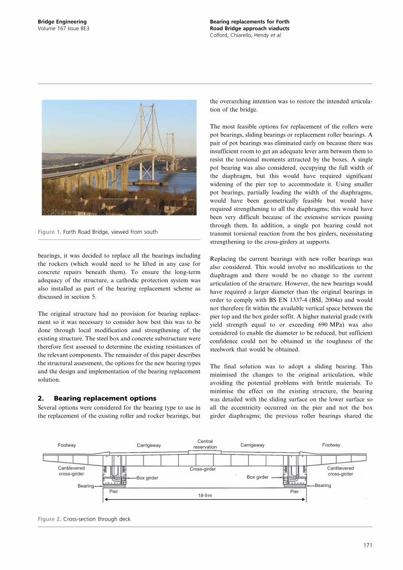
The Forth Road Bridge (Figure 1) spans the Firth of Forth
and was completed in 1964. The main structure is a three-span
suspension bridge. At each end of the bridge, there are two
multispan approach viaducts comprising a pair of long-
itudinal steel box girders with cross-girders supporting a
concrete deck slab as shown in Figure 2. The approach
viaducts carry two carriageways, each with two lanes, and
extend from the abutments to the side towers, which are
shared with the main suspension bridge. The total width of
the structure is 36 m.
The box girders rest on steel roller and rocker bearings on
reinforced concrete portal piers, varying between 11 m and
40 m high, founded on rock. The articulation of the two
viaducts is shown in Figure 3(a) and 3(b). Locations with roller
bearings allow for horizontal movement through movement of
the roller while the locations with rocker bearings allow for
movement through flexing of the piers.
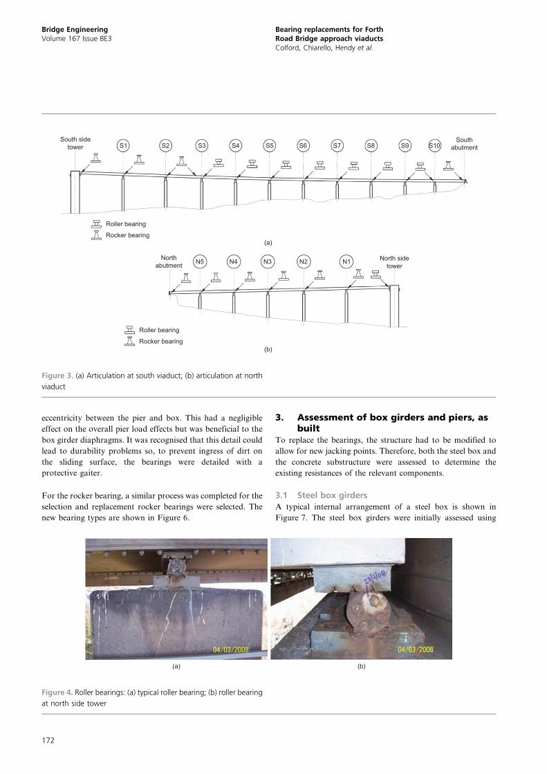
During inspections and displacement monitoring, the existing
roller bearings were found to exhibit little or no movement and
varying amounts of corrosion. At the north side tower, the
only roller bearing on the north viaduct, the roller was found
to be nearing the limit of its movement range. Figure 4(a)
shows a typical roller bearing, and Figure 4(b) shows the roller
at the north side tower. Structural assessment of the rollers
bearings to BS 5400-9-1:1983 (BSI, 1983) and BS EN 1337-4
(BSI, 2004a) showed that the original bearings did not meet
modern geometrical limits and were significantly overstressed
to the codes.
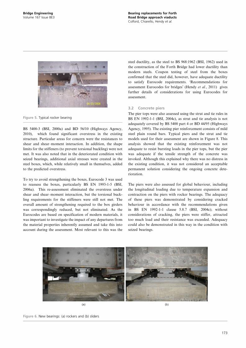
The rocker bearings were generally found to be in a better
condition than the rollers, although some corrosion was present.
A typical rocker bearing is seen in Figure 5. A structural
assessment was also performed on the rocker bearings, which
generally found that the bearings complied with the require-
ments set out in BS EN 1337-6:2004 (BSI, 2004b).
An inspection of the pier tops showed concrete delamination
occurring at many of the pier tops with patches of spalled
concrete in the regions directly below the bearings. Therefore,
the pier tops were tested for carbonation depth and chloride
contamination, which showed that many of the piers had high
chloride contents and were at risk of further deterioration.
Due to the poor concrete condition around and below the
Bridge EngineeringVolume 167 Issue BE3
Bearing replacements for Forth RoadBridge approach viaductsColford, Chiarello, Hendy et al.
Proceedings of the Institution of Civil Engineers
Bridge Engineering 167 September 2014 Issue BE3
Pages 170–182 http://dx.doi.org/10.1680/bren.11.00051
Paper 1100051
Received 11/11/2011 Accepted 11/05/2012
Published online 22/08/2013
Keywords: bridges/conservation/steel structures
ice | proceedings ICE Publishing: All rights reserved
170
bearings, it was decided to replace all the bearings including
the rockers (which would need to be lifted in any case for
concrete repairs beneath them). To ensure the long-term
adequacy of the structure, a cathodic protection system was
also installed as part of the bearing replacement scheme as
discussed in section 5.
The original structure had no provision for bearing replace-
ment so it was necessary to consider how best this was to be
done through local modification and strengthening of the
existing structure. The steel box and concrete substructure were
therefore first assessed to determine the existing resistances of
the relevant components. The remainder of this paper describes
the structural assessment, the options for the new bearing types
and the design and implementation of the bearing replacement
solution.
2. Bearing replacement options
Several options were considered for the bearing type to use in
the replacement of the existing roller and rocker bearings, but
the overarching intention was to restore the intended articula-
tion of the bridge.
The most feasible options for replacement of the rollers were
pot bearings, sliding bearings or replacement roller bearings. A
pair of pot bearings was eliminated early on because there was
insufficient room to get an adequate lever arm between them to
resist the torsional moments attracted by the boxes. A single
pot bearing was also considered, occupying the full width of
the diaphragm, but this would have required significant
widening of the pier top to accommodate it. Using smaller
pot bearings, partially loading the width of the diaphragms,
would have been geometrically feasible but would have
required strengthening to all the diaphragms; this would have
been very difficult because of the extensive services passing
through them. In addition, a single pot bearing could not
transmit torsional reaction from the box girders, necessitating
strengthening to the cross-girders at supports.
Replacing the current bearings with new roller bearings was
also considered. This would involve no modifications to the
diaphragm and there would be no change to the current
articulation of the structure. However, the new bearings would
have required a larger diameter than the original bearings in
order to comply with BS EN 1337-4 (BSI, 2004a) and would
not therefore fit within the available vertical space between the
pier top and the box girder soffit. A higher material grade (with
yield strength equal to or exceeding 690 MPa) was also
considered to enable the diameter to be reduced, but sufficient
confidence could not be obtained in the toughness of the
steelwork that would be obtained.
The final solution was to adopt a sliding bearing. This
minimised the changes to the original articulation, while
avoiding the potential problems with brittle materials. To
minimise the effect on the existing structure, the bearing
was detailed with the sliding surface on the lower surface so
all the eccentricity occurred on the pier and not the box
girder diaphragms; the previous roller bearings shared the
Figure 1. Forth Road Bridge, viewed from south
CarrlgewayFootway
BearingPier
Box girder Box girder
CarrigewayCentral
reservation
Cross-girderCantileveredcross-girder
Cantileveredcross-girder
Bearing
Footway
Pier18.9 m
▲
▲
Figure 2. Cross-section through deck
Bridge EngineeringVolume 167 Issue BE3
Bearing replacements for ForthRoad Bridge approach viaductsColford, Chiarello, Hendy et al.
171
eccentricity between the pier and box. This had a negligible
effect on the overall pier load effects but was beneficial to the
box girder diaphragms. It was recognised that this detail could
lead to durability problems so, to prevent ingress of dirt on
the sliding surface, the bearings were detailed with a
protective gaiter.
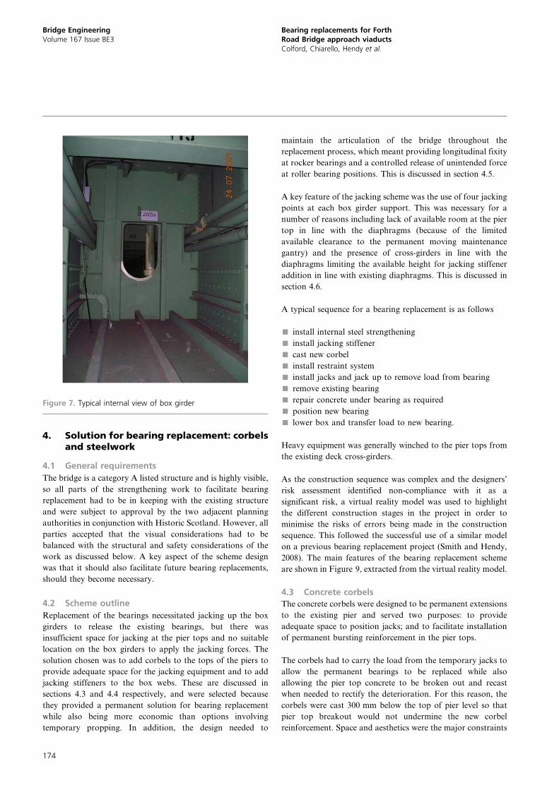
For the rocker bearing, a similar process was completed for the
selection and replacement rocker bearings were selected. The
new bearing types are shown in Figure 6.
3. Assessment of box girders and piers, asbuilt
To replace the bearings, the structure had to be modified to
allow for new jacking points. Therefore, both the steel box and
the concrete substructure were assessed to determine the
existing resistances of the relevant components.
3.1 Steel box girders
A typical internal arrangement of a steel box is shown in
Figure 7. The steel box girders were initially assessed using
(a) (b)
Figure 4. Roller bearings: (a) typical roller bearing; (b) roller bearing
at north side tower
South sidetower
Roller bearing
Rocker bearing(a)
(b)
Roller bearing
Rocker bearing
S1 S2 S3 S4 S5 S6 S7 S8 S9 S10South
abutment
North sidetower
Northabutment N5 N4 N3 N2 N1
Figure 3. (a) Articulation at south viaduct; (b) articulation at north
viaduct
Bridge EngineeringVolume 167 Issue BE3
Bearing replacements for ForthRoad Bridge approach viaductsColford, Chiarello, Hendy et al.
172
BS 5400-3 (BSI, 2000a) and BD 56/10 (Highways Agency,
2010), which found significant overstress in the existing
structure. Particular areas for concern were the resistances to
shear and shear–moment interaction. In addition, the shape
limits for the stiffeners (to prevent torsional buckling) were not
met. It was also noted that in the deteriorated condition with
seized bearings, additional axial stresses were created in the
steel boxes, which, while relatively small in themselves, added
to the predicted overstress.
To try to avoid strengthening the boxes, Eurocode 3 was used
to reassess the boxes, particularly BS EN 1993-1-5 (BSI,
2006a). This re-assessment eliminated the overstress under
shear and shear–moment interaction, but the torsional buck-
ling requirements for the stiffeners were still not met. The
overall amount of strengthening required to the box girders
was correspondingly reduced, but not eliminated. As the
Eurocodes are based on specification of modern materials, it
was important to investigate the impact of any departures from
the material properties inherently assumed and take this into
account during the assessment. Most relevant to this was the
steel ductility, as the steel to BS 968:1962 (BSI, 1962) used in
the construction of the Forth Bridge had lower ductility than
modern steels. Coupon testing of steel from the boxes
confirmed that the steel did, however, have adequate ductility
to satisfy Eurocode requirements. ‘Recommendations for
assessment Eurocodes for bridges’ (Hendy et al., 2011) gives
further details of considerations for using Eurocodes for
assessment.
3.2 Concrete piers
The pier tops were also assessed using the strut and tie rules in
BS EN 1992-1-1 (BSI, 2004c), as strut and tie analysis is not
adequately covered by BS 5400 part 4 or BD 44/95 (Highways
Agency, 1995). The existing pier reinforcement consists of mild
steel plain round bars. Typical piers and the strut and tie
models used for their assessment are shown in Figure 8. This
analysis showed that the existing reinforcement was not
adequate to resist bursting loads in the pier tops, but the pier
was adequate if the tensile strength of the concrete was
invoked. Although this explained why there was no distress in
the existing condition, it was not considered an acceptable
permanent solution considering the ongoing concrete dete-
rioration.
The piers were also assessed for global behaviour, including
the longitudinal loading due to temperature expansion and
contraction on the piers with rocker bearings. The adequacy
of these piers was demonstrated by considering cracked
behaviour in accordance with the recommendations given
in BS EN 1992-1-1 clause 5.8.7 (BSI, 2004c); without
considerations of cracking, the piers were stiffer, attracted
too much load and their resistance was exceeded. Adequacy
could also be demonstrated in this way in the condition with
seized bearings.
(a) (b)
Figure 6. New bearings: (a) rockers and (b) sliders
Figure 5. Typical rocker bearing
Bridge EngineeringVolume 167 Issue BE3
Bearing replacements for ForthRoad Bridge approach viaductsColford, Chiarello, Hendy et al.
173
4. Solution for bearing replacement: corbelsand steelwork
4.1 General requirements
The bridge is a category A listed structure and is highly visible,
so all parts of the strengthening work to facilitate bearing
replacement had to be in keeping with the existing structure
and were subject to approval by the two adjacent planning
authorities in conjunction with Historic Scotland. However, all
parties accepted that the visual considerations had to be
balanced with the structural and safety considerations of the
work as discussed below. A key aspect of the scheme design
was that it should also facilitate future bearing replacements,
should they become necessary.
4.2 Scheme outline
Replacement of the bearings necessitated jacking up the box
girders to release the existing bearings, but there was
insufficient space for jacking at the pier tops and no suitable
location on the box girders to apply the jacking forces. The
solution chosen was to add corbels to the tops of the piers to
provide adequate space for the jacking equipment and to add
jacking stiffeners to the box webs. These are discussed in
sections 4.3 and 4.4 respectively, and were selected because
they provided a permanent solution for bearing replacement
while also being more economic than options involving
temporary propping. In addition, the design needed to
maintain the articulation of the bridge throughout the
replacement process, which meant providing longitudinal fixity
at rocker bearings and a controlled release of unintended force
at roller bearing positions. This is discussed in section 4.5.
A key feature of the jacking scheme was the use of four jacking
points at each box girder support. This was necessary for a
number of reasons including lack of available room at the pier
top in line with the diaphragms (because of the limited
available clearance to the permanent moving maintenance
gantry) and the presence of cross-girders in line with the
diaphragms limiting the available height for jacking stiffener
addition in line with existing diaphragms. This is discussed in
section 4.6.
A typical sequence for a bearing replacement is as follows
& install internal steel strengthening
& install jacking stiffener
& cast new corbel
& install restraint system
& install jacks and jack up to remove load from bearing
& remove existing bearing
& repair concrete under bearing as required
& position new bearing
& lower box and transfer load to new bearing.
Heavy equipment was generally winched to the pier tops from
the existing deck cross-girders.
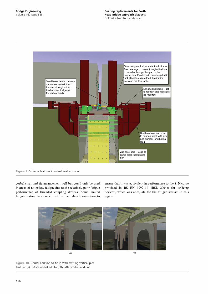
As the construction sequence was complex and the designers’
risk assessment identified non-compliance with it as a
significant risk, a virtual reality model was used to highlight
the different construction stages in the project in order to
minimise the risks of errors being made in the construction
sequence. This followed the successful use of a similar model
on a previous bearing replacement project (Smith and Hendy,
2008). The main features of the bearing replacement scheme
are shown in Figure 9, extracted from the virtual reality model.
4.3 Concrete corbels
The concrete corbels were designed to be permanent extensions
to the existing pier and served two purposes: to provide
adequate space to position jacks; and to facilitate installation
of permanent bursting reinforcement in the pier tops.
The corbels had to carry the load from the temporary jacks to
allow the permanent bearings to be replaced while also
allowing the pier top concrete to be broken out and recast
when needed to rectify the deterioration. For this reason, the
corbels were cast 300 mm below the top of pier level so that
pier top breakout would not undermine the new corbel
reinforcement. Space and aesthetics were the major constraints
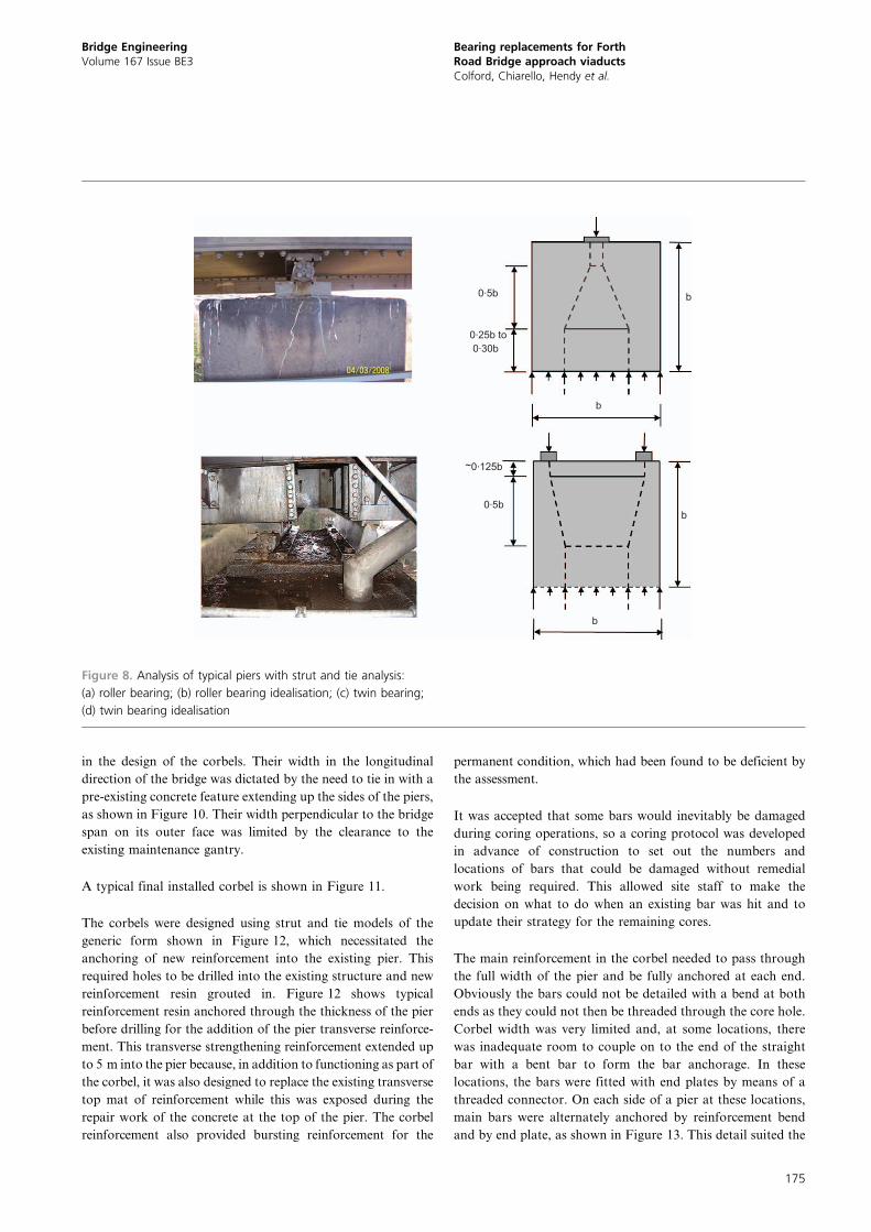
Figure 7. Typical internal view of box girder
Bridge EngineeringVolume 167 Issue BE3
Bearing replacements for ForthRoad Bridge approach viaductsColford, Chiarello, Hendy et al.
174
in the design of the corbels. Their width in the longitudinal
direction of the bridge was dictated by the need to tie in with a
pre-existing concrete feature extending up the sides of the piers,
as shown in Figure 10. Their width perpendicular to the bridge
span on its outer face was limited by the clearance to the
existing maintenance gantry.
A typical final installed corbel is shown in Figure 11.
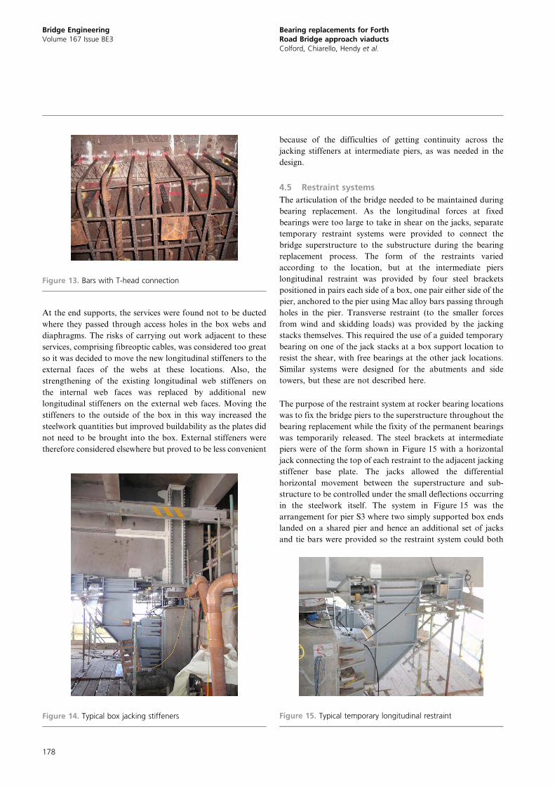
The corbels were designed using strut and tie models of the
generic form shown in Figure 12, which necessitated the
anchoring of new reinforcement into the existing pier. This
required holes to be drilled into the existing structure and new
reinforcement resin grouted in. Figure 12 shows typical
reinforcement resin anchored through the thickness of the pier
before drilling for the addition of the pier transverse reinforce-
ment. This transverse strengthening reinforcement extended up
to 5 m into the pier because, in addition to functioning as part of
the corbel, it was also designed to replace the existing transverse
top mat of reinforcement while this was exposed during the
repair work of the concrete at the top of the pier. The corbel
reinforcement also provided bursting reinforcement for the
permanent condition, which had been found to be deficient by
the assessment.
It was accepted that some bars would inevitably be damaged
during coring operations, so a coring protocol was developed
in advance of construction to set out the numbers and
locations of bars that could be damaged without remedial
work being required. This allowed site staff to make the
decision on what to do when an existing bar was hit and to
update their strategy for the remaining cores.
The main reinforcement in the corbel needed to pass through
the full width of the pier and be fully anchored at each end.
Obviously the bars could not be detailed with a bend at both
ends as they could not then be threaded through the core hole.
Corbel width was very limited and, at some locations, there
was inadequate room to couple on to the end of the straight
bar with a bent bar to form the bar anchorage. In these
locations, the bars were fitted with end plates by means of a
threaded connector. On each side of a pier at these locations,
main bars were alternately anchored by reinforcement bend
and by end plate, as shown in Figure 13. This detail suited the
b
b
b
b
0.5b
0.5b
0.25b to0.30b
~0.125b
Figure 8. Analysis of typical piers with strut and tie analysis:
(a) roller bearing; (b) roller bearing idealisation; (c) twin bearing;
(d) twin bearing idealisation
Bridge EngineeringVolume 167 Issue BE3
Bearing replacements for ForthRoad Bridge approach viaductsColford, Chiarello, Hendy et al.
175
corbel strut and tie arrangement well but could only be used
in areas of no or low fatigue due to the relatively poor fatigue
performance of threaded coupling devices. Some limited
fatigue testing was carried out on the T-head connection to
ensure that it was equivalent in performance to the S–N curve
provided in BS EN 1992-1-1 (BSI, 2004c) for ‘splicing
devices’, which was adequate for the fatigue stresses in this
region.
Steel baseplate – connectson to steel restraint fortransfer of longitudinalload and vertical jacksfor vertical loads
Longitudinal jacks – actto restrain and move pieras required
Mac alloy bars – used toclamp steel restraints topier
Steel restraint arm – actto connect deck with pierand transfer longitudinalload
Temporary vertical jack stack – includesfree bearings to prevent longitudinal loadto transfer through this part of theconnection. Elastomeric pack included injack stack to ensure load distributionbetween the four jacks
Figure 9. Scheme features in virtual reality model
(b)(a)
Figure 10. Corbel addition to tie in with existing vertical pier
feature: (a) before corbel additon; (b) after corbel addition
Bridge EngineeringVolume 167 Issue BE3
Bearing replacements for ForthRoad Bridge approach viaductsColford, Chiarello, Hendy et al.
176
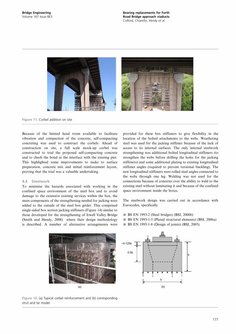
Because of the limited head room available to facilitate
vibration and compaction of the concrete, self-compacting
concreting was used to construct the corbels. Ahead of
construction on site, a full scale mock-up corbel was
constructed to trial the proposed self-compacting concrete
and to check the bond at the interface with the existing pier.
This highlighted some improvements to make to surface
preparation, concrete mix and initial reinforcement layout,
proving that the trial was a valuable undertaking.
4.4 Steelwork
To minimise the hazards associated with working in the
confined space environment of the steel box and to avoid
damage to the extensive existing services within the box, the
main components of the strengthening needed for jacking were
added to the outside of the steel box girder. This comprised
single-sided box section jacking stiffeners (Figure 14) similar to
those developed for the strengthening of Irwell Valley Bridge
(Smith and Hendy, 2008) where their design methodology
is described. A number of alternative arrangements were
provided for these box stiffeners to give flexibility in the
location of the bolted attachments to the webs. Weathering
steel was used for the jacking stiffener because of the lack of
access to its internal surfaces. The only internal steelwork
strengthening was additional bolted longitudinal stiffeners (to
strengthen the webs before drilling the holes for the jacking
stiffeners) and some additional plating to existing longitudinal
stiffener angles (required to prevent torsional buckling). The
new longitudinal stiffeners were rolled steel angles connected to
the webs through one leg. Welding was not used for the
connections because of concerns over the ability to weld to the
existing steel without laminating it and because of the confined
space environment inside the boxes.
The steelwork design was carried out in accordance with
Eurocodes, specifically
& BS EN 1993-2 (Steel bridges) (BSI, 2006b)
& BS EN 1993-1-5 (Plated structural elements) (BSI, 2006a)
& BS EN 1993-1-8 (Design of joints) (BSI, 2005).
Figure 11. Corbel addition on site
b
b0.5b
(a) (b)
~0.125b
Figure 12. (a) Typical corbel reinforcement and (b) corresponding
strut and tie model
Bridge EngineeringVolume 167 Issue BE3
Bearing replacements for ForthRoad Bridge approach viaductsColford, Chiarello, Hendy et al.
177
At the end supports, the services were found not to be ducted
where they passed through access holes in the box webs and
diaphragms. The risks of carrying out work adjacent to these
services, comprising fibreoptic cables, was considered too great
so it was decided to move the new longitudinal stiffeners to the
external faces of the webs at these locations. Also, the
strengthening of the existing longitudinal web stiffeners on
the internal web faces was replaced by additional new
longitudinal stiffeners on the external web faces. Moving the
stiffeners to the outside of the box in this way increased the
steelwork quantities but improved buildability as the plates did
not need to be brought into the box. External stiffeners were
therefore considered elsewhere but proved to be less convenient
because of the difficulties of getting continuity across the
jacking stiffeners at intermediate piers, as was needed in the
design.
4.5 Restraint systems
The articulation of the bridge needed to be maintained during
bearing replacement. As the longitudinal forces at fixed
bearings were too large to take in shear on the jacks, separate
temporary restraint systems were provided to connect the
bridge superstructure to the substructure during the bearing
replacement process. The form of the restraints varied
according to the location, but at the intermediate piers
longitudinal restraint was provided by four steel brackets
positioned in pairs each side of a box, one pair either side of the
pier, anchored to the pier using Mac alloy bars passing through
holes in the pier. Transverse restraint (to the smaller forces
from wind and skidding loads) was provided by the jacking
stacks themselves. This required the use of a guided temporary
bearing on one of the jack stacks at a box support location to
resist the shear, with free bearings at the other jack locations.
Similar systems were designed for the abutments and side
towers, but these are not described here.
The purpose of the restraint system at rocker bearing locations
was to fix the bridge piers to the superstructure throughout the
bearing replacement while the fixity of the permanent bearings
was temporarily released. The steel brackets at intermediate
piers were of the form shown in Figure 15 with a horizontal
jack connecting the top of each restraint to the adjacent jacking
stiffener base plate. The jacks allowed the differential
horizontal movement between the superstructure and sub-
structure to be controlled under the small deflections occurring
in the steelwork itself. The system in Figure 15 was the
arrangement for pier S3 where two simply supported box ends
landed on a shared pier and hence an additional set of jacks
and tie bars were provided so the restraint system could both
Figure 13. Bars with T-head connection
Figure 14. Typical box jacking stiffeners Figure 15. Typical temporary longitudinal restraint
Bridge EngineeringVolume 167 Issue BE3
Bearing replacements for ForthRoad Bridge approach viaductsColford, Chiarello, Hendy et al.
178
push and pull. At continuous box locations these additional
features were unnecessary as the restraints only needed to carry
forces in one direction. The horizontal restraint jacks were
engaged before lifting the superstructure and remained
engaged during the bearing replacement until the girders were
lowered down onto the new bearings.
The restraint systems at roller bearing locations were similar
but were provided only to control the release of force locked
into the roller bearings. It was known such forces existed from
earlier pier monitoring. Lifting of the superstructure under
these conditions could have caused a sudden release of
horizontal force and a springing back of the pier in a
potentially dangerous sudden movement. The provision of
jacks allowed this force and movement to be released in a
controlled and safe manner.
In all cases, generous allowance for eccentricities was made in
the design of the steelwork because aligning the temporary
restraint brackets, whose position was fixed by the locations of
the core holes for the Mac alloy bars, with the jacking stiffener
base plate stiffening had significant tolerance.
As a result of this provision of temporary fixity, no limit was set
on the number of piers that could be jacked up at any one time.
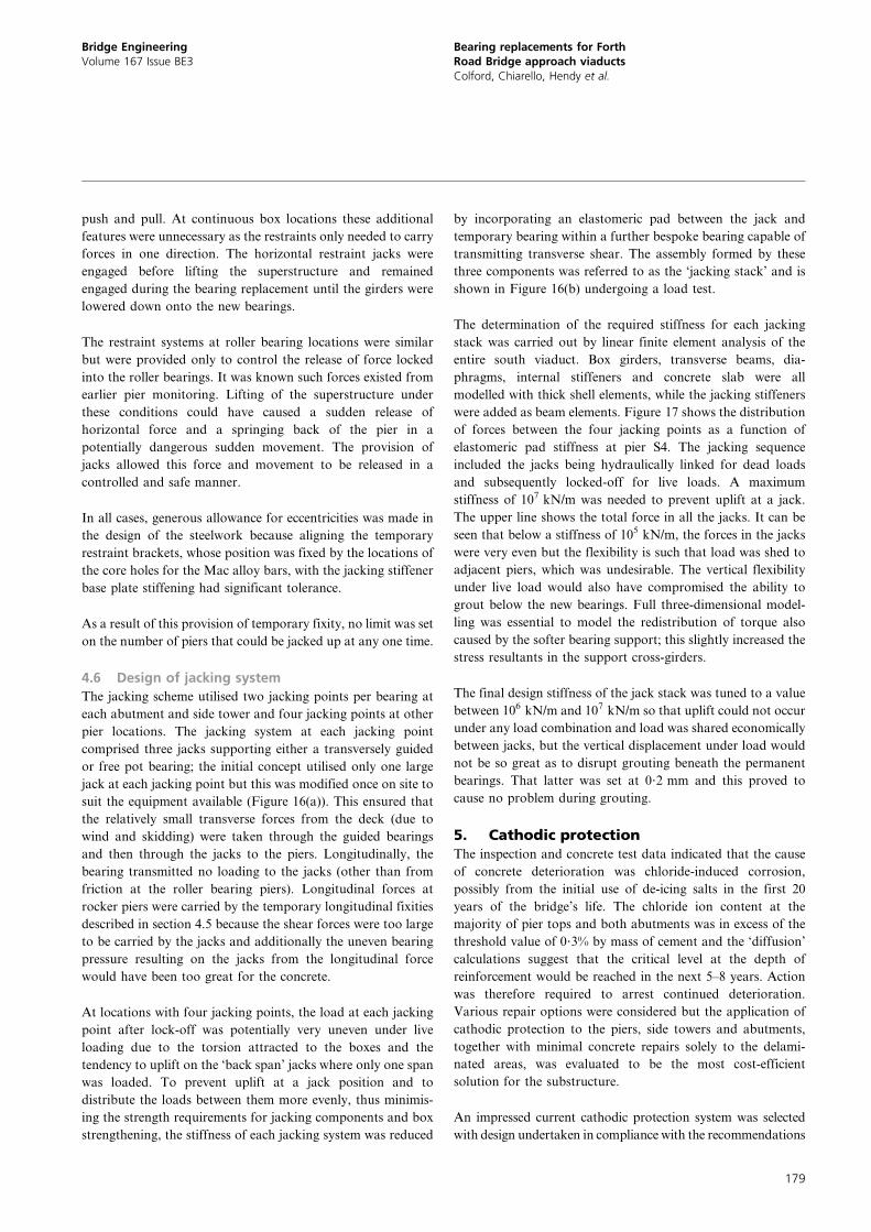
4.6 Design of jacking system
The jacking scheme utilised two jacking points per bearing at
each abutment and side tower and four jacking points at other
pier locations. The jacking system at each jacking point
comprised three jacks supporting either a transversely guided
or free pot bearing; the initial concept utilised only one large
jack at each jacking point but this was modified once on site to
suit the equipment available (Figure 16(a)). This ensured that
the relatively small transverse forces from the deck (due to
wind and skidding) were taken through the guided bearings
and then through the jacks to the piers. Longitudinally, the
bearing transmitted no loading to the jacks (other than from
friction at the roller bearing piers). Longitudinal forces at
rocker piers were carried by the temporary longitudinal fixities
described in section 4.5 because the shear forces were too large
to be carried by the jacks and additionally the uneven bearing
pressure resulting on the jacks from the longitudinal force
would have been too great for the concrete.
At locations with four jacking points, the load at each jacking
point after lock-off was potentially very uneven under live
loading due to the torsion attracted to the boxes and the
tendency to uplift on the ‘back span’ jacks where only one span
was loaded. To prevent uplift at a jack position and to
distribute the loads between them more evenly, thus minimis-
ing the strength requirements for jacking components and box
strengthening, the stiffness of each jacking system was reduced
by incorporating an elastomeric pad between the jack and
temporary bearing within a further bespoke bearing capable of
transmitting transverse shear. The assembly formed by these
three components was referred to as the ‘jacking stack’ and is
shown in Figure 16(b) undergoing a load test.
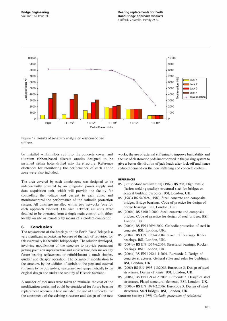
The determination of the required stiffness for each jacking
stack was carried out by linear finite element analysis of the
entire south viaduct. Box girders, transverse beams, dia-
phragms, internal stiffeners and concrete slab were all
modelled with thick shell elements, while the jacking stiffeners
were added as beam elements. Figure 17 shows the distribution
of forces between the four jacking points as a function of
elastomeric pad stiffness at pier S4. The jacking sequence
included the jacks being hydraulically linked for dead loads
and subsequently locked-off for live loads. A maximum
stiffness of 107 kN/m was needed to prevent uplift at a jack.
The upper line shows the total force in all the jacks. It can be
seen that below a stiffness of 105 kN/m, the forces in the jacks
were very even but the flexibility is such that load was shed to
adjacent piers, which was undesirable. The vertical flexibility
under live load would also have compromised the ability to
grout below the new bearings. Full three-dimensional model-
ling was essential to model the redistribution of torque also
caused by the softer bearing support; this slightly increased the
stress resultants in the support cross-girders.
The final design stiffness of the jack stack was tuned to a value
between 106 kN/m and 107 kN/m so that uplift could not occur
under any load combination and load was shared economically
between jacks, but the vertical displacement under load would
not be so great as to disrupt grouting beneath the permanent
bearings. That latter was set at 0?2 mm and this proved to
cause no problem during grouting.
5. Cathodic protectionThe inspection and concrete test data indicated that the cause
of concrete deterioration was chloride-induced corrosion,
possibly from the initial use of de-icing salts in the first 20
years of the bridge’s life. The chloride ion content at the
majority of pier tops and both abutments was in excess of the
threshold value of 0?3% by mass of cement and the ‘diffusion’
calculations suggest that the critical level at the depth of
reinforcement would be reached in the next 5–8 years. Action
was therefore required to arrest continued deterioration.
Various repair options were considered but the application of
cathodic protection to the piers, side towers and abutments,
together with minimal concrete repairs solely to the delami-
nated areas, was evaluated to be the most cost-efficient
solution for the substructure.
An impressed current cathodic protection system was selected
with design undertaken in compliance with the recommendations
Bridge EngineeringVolume 167 Issue BE3
Bearing replacements for ForthRoad Bridge approach viaductsColford, Chiarello, Hendy et al.
179
of BS EN 12696:2000 (BSI, 2000b), the National Association
of Concrete Engineers (NACE, 2000) and the Concrete
Society report (Concrete Society, 1989). Three types of
anode systems were used in the design: titanium mesh-
based anode to be installed at the interface of concrete
substrate and new corbels; titanium ribbon-based anodes to
270
175
127
202 30Jack
(a)
(b)
Stiffener base plate 50 mm thickTemporary bearing.ref. FRB/FR/01Flexible rubber padbearing
Lower steel spreaderplate 50 mm thickJack ref. FRB/JK/01420 Ø
CL
98
5082
Upper keep plates bolted toflexible rubber pad bearing (seedrawing no. 5057541/501/250)Lower keep plates bolted to lowerspreader plate 50 mm thick (see section H-H)Non-shrink grout (thicknessvaries to suit spreader plate15 mm min.)
Holding down bolts to be M30
Packing plateBottom flangeBox girder web
Cheese plate
Jacking stiffenerBottom surface of allvertical stiffener plates tobe fitted (ƒ)
ƒƒ
ƒ
ƒ
ƒ
z8 Fillet weld around perimeterof bearing base plate
Figure 16. Jacking stack: (a) concept with single jack (dimensions
in mm); (b) final three-jack system undergoing load test
Bridge EngineeringVolume 167 Issue BE3
Bearing replacements for ForthRoad Bridge approach viaductsColford, Chiarello, Hendy et al.
180
be installed within slots cut into the concrete cover; and
titanium ribbon-based discrete anodes designed to be
installed within holes drilled into the structure. Reference
electrodes for monitoring the performance of each anode
zone were also included.
The area covered by each anode zone was designed to be
independently powered by an integrated power supply and
data acquisition unit, which will provide the facility for
controlling the voltage and current to each zone; and
monitor/control the performance of the cathodic protection
system. All units are installed within two networks (one for
each approach viaduct). On each network all units were
detailed to be operated from a single main control unit either
locally on site or remotely by means of a modem connection.
6. ConclusionThe replacement of the bearings on the Forth Road Bridge is a
very significant undertaking because of the lack of provision for
this eventuality in the initial bridge design. The solution developed,
involving modification of the structure to provide permanent
jacking points on superstructure and substructure, now makes any
future bearing replacement or refurbishment a much simpler,
quicker and cheaper operation. The permanent modification to
the structure, by the addition of corbels to the piers and external
stiffening to the box girders, was carried out sympathetically to the
original design and under the scrutiny of Historic Scotland.
A number of measures were taken to minimise the cost of the
modification works and could be considered for future bearing
replacement schemes. These included the use of Eurocodes for
the assessment of the existing structure and design of the new
works, the use of external stiffening to improve buildability and
the use of elastomeric pads incorporated in the jacking system to
give a better distribution of jack loads after lock-off and hence
reduced demand on the new stiffening and concrete corbels.
REFERENCES
BSI (British Standards Institute) (1962) BS 968, High tensile
(fusion welding quality) structural steel for bridges or
general building purposes. BSI, London, UK.
BSI (1983) BS 5400-9-1:1983. Steel, concrete and composite
bridges. Bridge bearings. Code of practice for design of
bridge bearings. BSI, London, UK.
BSI (2000a) BS 5400-3:2000. Steel, concrete and composite
bridges. Code of practice for design of steel bridges. BSI,
London, UK.
BSI (2000b) BS EN 12696:2000. Cathodic protection of steel in
concrete. BSI, London, UK.
BSI (2004a) BS EN 1337-4:2004. Structural bearings. Roller
bearings. BSI, London, UK.
BSI (2004b) BS EN 1337-6:2004. Structural bearings. Rocker
bearings. BSI, London, UK.
BSI (2004c) BS EN 1992-1-1:2004. Eurocode 2. Design of
concrete structures. General rules and rules for buildings.
BSI, London, UK.
BSI (2005) BS EN 1993-1-8:2005. Eurocode 3. Design of steel
structures. Design of joints. BSI, London, UK.
BSI (2006a) BS EN 1993-1-5:2006. Eurocode 3. Design of steel
structures. Plated structural elements. BSI, London, UK.
BSI (2006b) BS EN 1993-2:2006. Eurocode 3. Design of steel
structures. Steel bridges. BSI, London, UK.
Concrete Society (1989) Cathodic protection of reinforced
9000
8000
7000
6000
5000
4000
3000
2000
1000
10 000
0
9000
8000
7000
6000Jack 1Jack 2Jack 3Jack 4Total reaction
5000
4000
3000
2000
1000
10 000
0Rigid 1 × 10⁷ 1 × 10⁶ 1 × 1031 × 1041 × 105
Pad stiffness: Kn/m
Jack
reac
tions
: KN
Tota
l rea
ctio
n (K
N)
Figure 17. Results of sensitivity analysis on elastomeric pad
stiffness
Bridge EngineeringVolume 167 Issue BE3
Bearing replacements for ForthRoad Bridge approach viaductsColford, Chiarello, Hendy et al.
181
concrete. Concrete Society (Corrosion Engineering
Association), Camberley, UK. Technical report no. 36.
Hendy CR, Sandberg J and Shetty NK (2011) Recommendations
for assessment Eurocodes for bridges. Proceedings of the
ICE – Bridge Engineering 164(1): 3–14. http://dx.doi.org/10.
1680/bren.900030.
Highways Agency (1995) BD 44/95, The assessment of concrete
highway bridges and structures. Highways Agency,
London, UK.
Highways Agency (2010) BD 56/10, The assessment of steel
highway bridges and structures. Highways Agency,
London, UK.
NACE (National Association of Corrosion Engineers) (2000)
Standard Recommended Practice – Cathodic Protection of
Reinforcing Steel in Atmospherically Exposed Concrete
Structures. NACE International, Houston, TX, USA.
Smith DA and Hendy CR (2008) Strengthening of Irwell Valley
Bridge, UK. Proceedings of the ICE – Bridge Engineering
161(1): 33–43. http://dx.doi.org/10.1680/bren.2008.
161.1.33.
WHAT DO YOU THINK?
To discuss this paper, please email up to 500 words to the
editor at [email protected]. Your contribution will be
forwarded to the author(s) for a reply and, if considered
appropriate by the editorial panel, will be published as
discussion in a future issue of the journal.
Proceedings journals rely entirely on contributions sent in
by civil engineering professionals, academics and stu-
dents. Papers should be 2000–5000 words long (briefing
papers should be 1000–2000 words long), with adequate
illustrations and references. You can submit your paper
online via www.icevirtuallibrary.com/content/journals,
where you will also find detailed author guidelines.
Bridge EngineeringVolume 167 Issue BE3
Bearing replacements for ForthRoad Bridge approach viaductsColford, Chiarello, Hendy et al.
182
Recommended