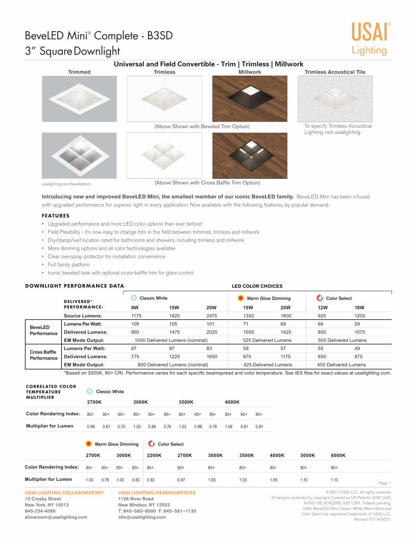
Introducing new and improved BeveLED Mini, the smallest member of our iconic BeveLED family. BeveLED Mini has been infused
with upgraded performance for superior light in every application. Now available with the following features, by popular demand:
FEATURES
• Upgraded performance and more LED color options than ever before!
• Field Flexibility - it’s now easy to change trim in the fi eld between trimmed, trimless and millwork
• Dry/damp/wet location rated for bathrooms and showers, including trimless and millwork
• More dimming options and all color technologies available
• Clear overspray protector for installation convenience
• Full family platform
• Iconic beveled look with optional cross-baffl e trim for glare control
Page 1
3” Square Downlight
USAI LIGHTING HEADQUARTERS1126 River RoadNew Windsor, NY 12553T: 845–565–8500 F: 845–561–[email protected]
USAI LIGHTING COLLABORATORY13 Crosby StreetNew York, NY [email protected]
BeveLED Mini® Complete - B3SD
© 2017. USAI, LLC. All rights reserved. All designs protected by copyright. Covered by US Patents: 8,581,520,
8,456,109, 8,742,695, 9,671,091. Patents pending. USAI, BeveLED Mini, Classic White, Warm Glow and
Color Select are registered trademarks of USAI, LLC.Revised 07/14/2021
Universal and Field Convertible - Trim | Trimless | Millwork
usailighting.com/beveledmini
DOWNLIGHT PERFORMANCE DATA
Classic White
LED COLOR CHOICES
9W 15W 20W 15W 20W 12W 18WSource Lumens: 1175 1825 2475 1350 1800 925 1200
Lumens Per Watt: 105 105 101 71 69 66 59
Delivered Lumens: 950 1475 2025 1050 1425 800 1075
EM Mode Output: 1000 Delivered Lumens (nominal) 525 Delivered Lumens 500 Delivered Lumens
Lumens Per Watt: 87 87 83 58 57 55 49
Delivered Lumens: 775 1225 1650 875 1175 650 875
EM Mode Output: 800 Delivered Lumens (nominal) 425 Delivered Lumens 400 Delivered Lumens
*Based on 3000K, 80+ CRI. Performance varies for each specifi c beamspread and color temperature. See IES fi les for exact values at usailighting.com.
DELIVERED*PERFORMANCE:
Color Rendering Index:
Multiplier for Lumen
CORRELATED COLOR TEMPERATURE MULTIPLIER
Classic White
2700K 3000K 3500K 4000K
80+ 90+ 95+ 80+ 90+ 95+ 80+ 90+ 95+ 80+ 90+ 95+
0.96 0.81 0.70 1.00 0.86 0.74 1.03 0.88 0.79 1.06 0.81 0.81
Color Rendering Index:
Multiplier for Lumen
Warm Glow Dimming Color Select
2700K 3000K 2200K 2700K 3000K 3500K 4000K 5000K 6000K
80+ 90+ 80+ 90+ 80+ 80+ 80+ 80+ 80+ 80+ 80+
1.00 0.78 1.00 0.83 0.92 0.97 1.00 1.03 1.05 1.10 1.13
Warm Glow Dimming Color Select
Trimmed Trimless Millwork
To specify Trimless Acoustical Lighting visit usailighting.
Trimless Acoustical Tile
(Above Shown with Beveled Trim Option)
(Above Shown with Cross Baffl e Trim Option)
BeveLEDPerformance
Cross Baffl ePerformance
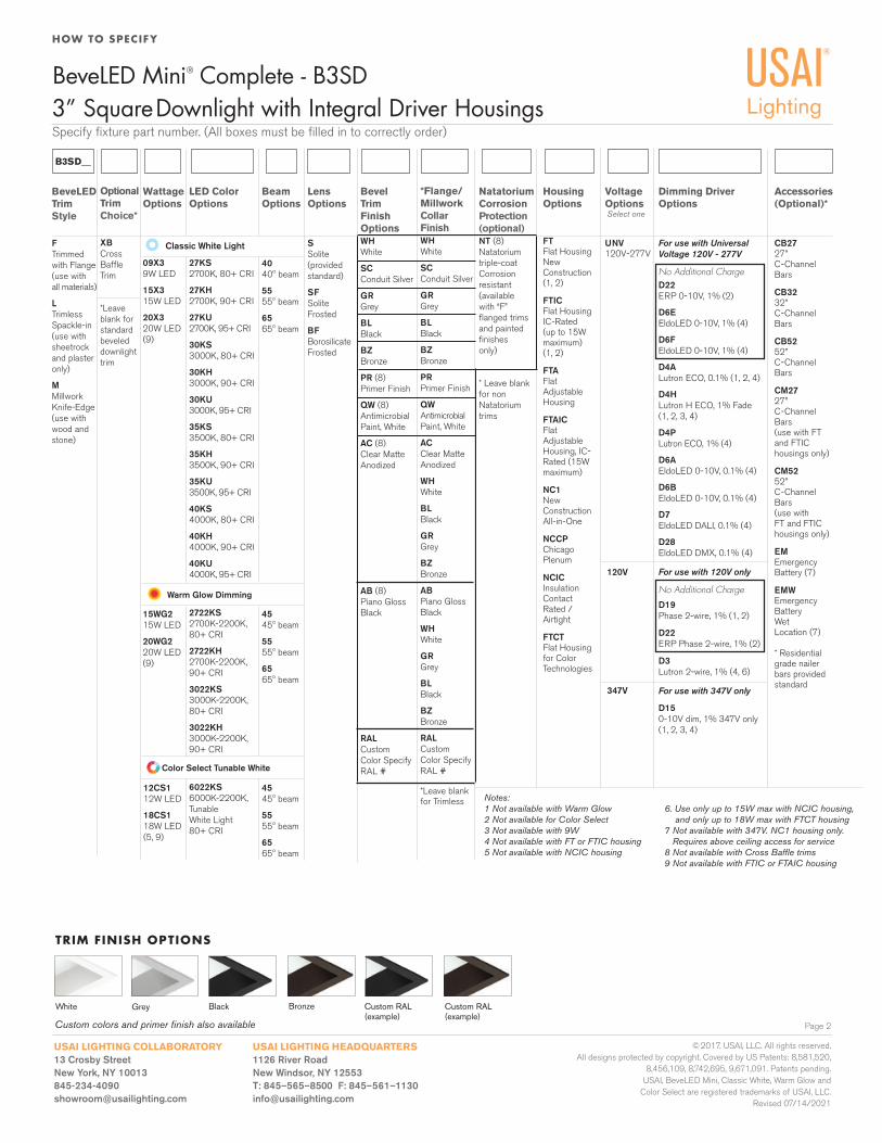
Specify fi xture part number. (All boxes must be fi lled in to correctly order)
HOW TO SPECIFY
3” Square Downlight with Integral Driver Housings
Page 2
USAI LIGHTING HEADQUARTERS1126 River RoadNew Windsor, NY 12553T: 845–565–8500 F: 845–561–[email protected]
USAI LIGHTING COLLABORATORY13 Crosby StreetNew York, NY [email protected]
BeveLED Mini® Complete - B3SD
© 2017. USAI, LLC. All rights reserved. All designs protected by copyright. Covered by US Patents: 8,581,520,
8,456,109, 8,742,695, 9,671,091. Patents pending. USAI, BeveLED Mini, Classic White, Warm Glow and
Color Select are registered trademarks of USAI, LLC.Revised 07/14/2021
TRIM FINISH OPTIONS
Custom colors and primer fi nish also available
BronzeBlackGreyWhite Custom RAL (example)
Custom RAL (example)
B3SD__
Classic White Light
Select one
HousingOptions
FT Flat Housing New Construction(1, 2)
FTICFlat Housing IC-Rated (up to 15W maximum) (1, 2)
FTAFlat Adjustable Housing
FTAICFlat Adjustable Housing, IC-Rated (15W maximum)
NC1NewConstructionAll-in-One
NCCP ChicagoPlenum
NCICInsulation Contact Rated / Airtight
FTCTFlat Housing for Color Technologies
Color Select Tunable White
Warm Glow Dimming
120V
347V
LensOptions
SSolite (provided standard)
SFSolite Frosted
BFBorosilicate Frosted
BeveLEDTrimStyle
FTrimmed with Flange (use with all materials)
LTrimless Spackle-in (use with sheetrock and plaster only)
MMillwork Knife-Edge (use with wood and stone)
WattageOptions
09X39W LED
15X315W LED
20X320W LED(9)
LED ColorOptions
27KS2700K, 80+ CRI
27KH2700K, 90+ CRI
27KU2700K, 95+ CRI
30KS3000K, 80+ CRI
30KH3000K, 90+ CRI
30KU3000K, 95+ CRI
35KS3500K, 80+ CRI
35KH3500K, 90+ CRI
35KU3500K, 95+ CRI
40KS4000K, 80+ CRI
40KH4000K, 90+ CRI
40KU4000K, 95+ CRI
2722KS2700K-2200K, 80+ CRI
2722KH2700K-2200K, 90+ CRI
3022KS3000K-2200K, 80+ CRI
3022KH3000K-2200K, 90+ CRI
6022KS6000K-2200K, Tunable White Light 80+ CRI
Dimming DriverOptions
For use with UniversalVoltage 120V - 277V
No Additional ChargeD22 ERP 0-10V, 1% (2)
D6EEldoLED 0-10V, 1% (4)
D6F EldoLED 0-10V, 1% (4)
D4A Lutron ECO, 0.1% (1, 2, 4)
D4H Lutron H ECO, 1% Fade (1, 2, 3, 4)
D4P Lutron ECO, 1% (4)
D6A EldoLED 0-10V, 0.1% (4)
D6B EldoLED 0-10V, 0.1% (4)
D7 EldoLED DALI, 0.1% (4)
D28 EldoLED DMX, 0.1% (4)
For use with 120V only
No Additional Charge
D19 Phase 2-wire, 1% (1, 2)
D22 ERP Phase 2-wire, 1% (2)
D3 Lutron 2-wire, 1% (4, 6)
For use with 347V only
D15 0-10V dim, 1% 347V only (1, 2, 3, 4)
15WG215W LED
20WG220W LED(9)
12CS1 12W LED
18CS118W LED (5, 9)
BeamOptions
4040º beam
5555º beam
6565º beam
BevelTrim FinishOptionsWHWhite
SCConduit Silver
GRGrey
BLBlack
BZBronze
PR (8)Primer Finish
QW (8)Antimicrobial Paint, White
AC (8)Clear Matte Anodized
AB (8)Piano Gloss Black
RALCustom Color Specify RAL #
VoltageOptions
UNV120V-277V
Accessories(Optional)*
CB27 27”C-Channel Bars
CB3232” C-Channel Bars
CB5252” C-Channel Bars
CM2727” C-Channel Bars(use with FT and FTIChousings only)
CM5252” C-Channel Bars(use with FT and FTIChousings only)
EMEmergency Battery (7)
EMWEmergency BatteryWet Location (7)
* Residential grade nailer bars provided standard
*Flange/MillworkCollar FinishWHWhite
SCConduit Silver
GRGrey
BLBlack
BZBronze
PRPrimer Finish
QWAntimicrobial Paint, White
ACClear Matte Anodized
WHWhite
BLBlack
GRGrey
BZBronze
ABPiano Gloss Black
WHWhite
GRGrey
BLBlack
BZBronze
RALCustom Color Specify RAL #
*Leave blankfor Trimless Notes:
1 Not available with Warm Glow 6. Use only up to 15W max with NCIC housing,2 Not available for Color Select and only up to 18W max with FTCT housing3 Not available with 9W 7 Not available with 347V. NC1 housing only.4 Not available with FT or FTIC housing Requires above ceiling access for service5 Not available with NCIC housing 8 Not available with Cross Baffl e trims 9 Not available with FTIC or FTAIC housing
NatatoriumCorrosionProtection (optional)NT (8)Natatoriumtriple-coatCorrosionresistant(available with “F” fl anged trims and painted fi nishesonly)
* Leave blankfor nonNatatoriumtrims
OptionalTrimChoice*
XBCross Baffl e Trim
*Leave blank for standard beveled downlight trim
4545º beam
5555º beam
6565º beam
4545º beam
5555º beam
6565º beam
HOW TO SPECIFY
3” Square Downlight with Remote Driver
Page 3
USAI LIGHTING HEADQUARTERS1126 River RoadNew Windsor, NY 12553T: 845–565–8500 F: 845–561–[email protected]
USAI LIGHTING COLLABORATORY13 Crosby StreetNew York, NY [email protected]
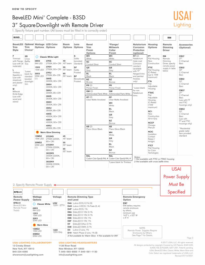
1. Specify fi xture part number. (All boxes must be fi lled in to correctly order)
BeveLED Mini® Complete - B3SD
© 2017. USAI, LLC. All rights reserved. All designs protected by copyright. Covered by US Patents: 8,581,520,
8,456,109, 8,742,695, 9,671,091. Patents pending. USAI, BeveLED Mini, Classic White, Warm Glow and
Color Select are registered trademarks of USAI, LLC.Revised 07/14/2021
B3SD__
Classic White Light
HousingOptions
FT Flat Housing New Construction
FTICFlat Housing IC-Rated (up to 15W maximum)
FTAFlat Adjustable Housing
FTAICFlat Adjustable Housing,IC-Rated (15W maximum)
NC1NewConstructionAll-in-One
NCCP ChicagoPlenum
NCICInsulation Contact Rated / Airtight
FTCTFlat Housingfor ColorTechologies
Warm Glow Dimming
BeveLEDTrim Style
FTrimmed with Flange (use with all materials)
LTrimless Spackle-in (use with sheetrock and plaster only)
MMillwork Knife-Edge (use with wood and stone)
WattageOptions
09X39W LED
15X315W LED
20X320W LED(1)
LED ColorOptions
27KS2700K, 80+ CRI
27KH2700K, 90+ CRI
27KU2700K, 95+ CRI
30KS3000K, 80+ CRI
30KH3000K, 90+ CRI
30KU3000K, 95+ CRI
35KS3500K, 80+ CRI
35KH3500K, 90+ CRI
35KU3500K, 95+ CRI
40KS4000K, 80+ CRI
40KH4000K, 90+ CRI
40KU4000K, 95+ CRI
2722KS2700K-2200K, 80+ CRI
2722KH2700K-2200K, 90+ CRI
3022KS3000K-2200K, 80+ CRI
3022KH3000K-2200K, 90+ CRI
15WG215W LED
20WG220W LED(1)
BeamOptions
4040º beam
5555º beam
6565º beam
Accessories(Optional)
CB27 27” C-Channel Bars
CB3232” C-Channel Bars
CB5252” C-Channel Bars
CM2727” C-Channel Bars(use with FT and FTIChousings only)
CM5252” C-Channel Bars(use with FT and FTIChousings only)
* Residential grade nailer bars provided standard
RM
Remote DimmingDriver
RM Remote DimmingDriver, specify remote power supply in table below
RPB-01
Remote Power SupplyRPB-01BeveLED Mini Remote PowerSupply
WattageOptions
09X39W LED15X3 15W LED20X3 20W LED
Remote Dimming Typeand LevelD4A Lutron ECO, 0.1% (3)D4H Lutron H ECO, 1% Fade (3, 4)D4P Lutron ECO, 1% D6A EldoLED 0-10V, 0.1%D6B EldoLED 0-10V, 0.1%D6E EldoLED 0-10V, 1%D6F EldoLED 0-10V, 1%D7 EldoLED DALI, 0.1% D28 EldoLED DMX, 0.1% D3 Lutron 2-wire, 1%D19 Hatch Phase 2-wire, 1% (3)3 Not available for Warm Glow 4 Not available for 9W
Remote EmergencyOptionEM7EM battery requiresremote enclosureby others, minimum size14.5” L x 6.5” Wx 3” H
Voltage
UNV 120V - 277V
120V 120V Only
Classic White
Warm Glow
15WG2 15W LED20WG2 20W LED
2. Specify Remote Power Supply
NOTE:Remote Power Supplies Require
Enclosures by Others. See Page 7 for Details.
LensOptions
SSolite (provided standard)
SFSolite Frosted
BFBorosilicate Frosted
USAI
Power Supply
Must Be
Specifi ed
*Flange/MillworkCollarFinishWHWhite
SCConduit Silver
GRGrey
BLBlack
BZBronze
PRPrimer Finish
QWAntimicrobial Paint, White
ACClear Matte Anodized
WHWhite
BLBlack
GRGrey
BZBronze
ABPiano Gloss Black
WHWhite
GRGrey
BLBlack
BZBronze
RALCustom Color Specify RAL #
*Leave blank for Trimless
BevelTrimFinishOptionsWHWhite
SCConduit Silver
GRGrey
BLBlack
BZBronze
PR (2)Primer Finish
QW (2)Antimicrobial Paint, White
AC (2)Clear Matte Anodized
AB (2)Piano Gloss Black
RALCustom Color Specify RAL #
NatatoriumCorrosionProtection (optional)NT (2)Natatoriumtriple-coatCorrosionresistant(available with “F” fl anged trims and painted fi nishesonly)
* Leave blankfor nonNatatoriumtrims
OptionalTrimChoice*
XBCross Baffl e Trim
*Leave blank for standard beveled downlight trim
4545º beam
5555º beam
6565º beam
Notes: 1 Not available with FTIC or FTAIC housing2 Not available with cross baffl e trims
Page 4
3” Square Downlight
USAI LIGHTING HEADQUARTERS1126 River RoadNew Windsor, NY 12553T: 845–565–8500 F: 845–561–[email protected]
USAI LIGHTING COLLABORATORY13 Crosby StreetNew York, NY [email protected]
BeveLED Mini® Complete - B3SD
© 2017. USAI, LLC. All rights reserved. All designs protected by copyright. Covered by US Patents: 8,581,520,
8,456,109, 8,742,695, 9,671,091. Patents pending. USAI, BeveLED Mini, Classic White, Warm Glow and
Color Select are registered trademarks of USAI, LLC.Revised 07/14/2021
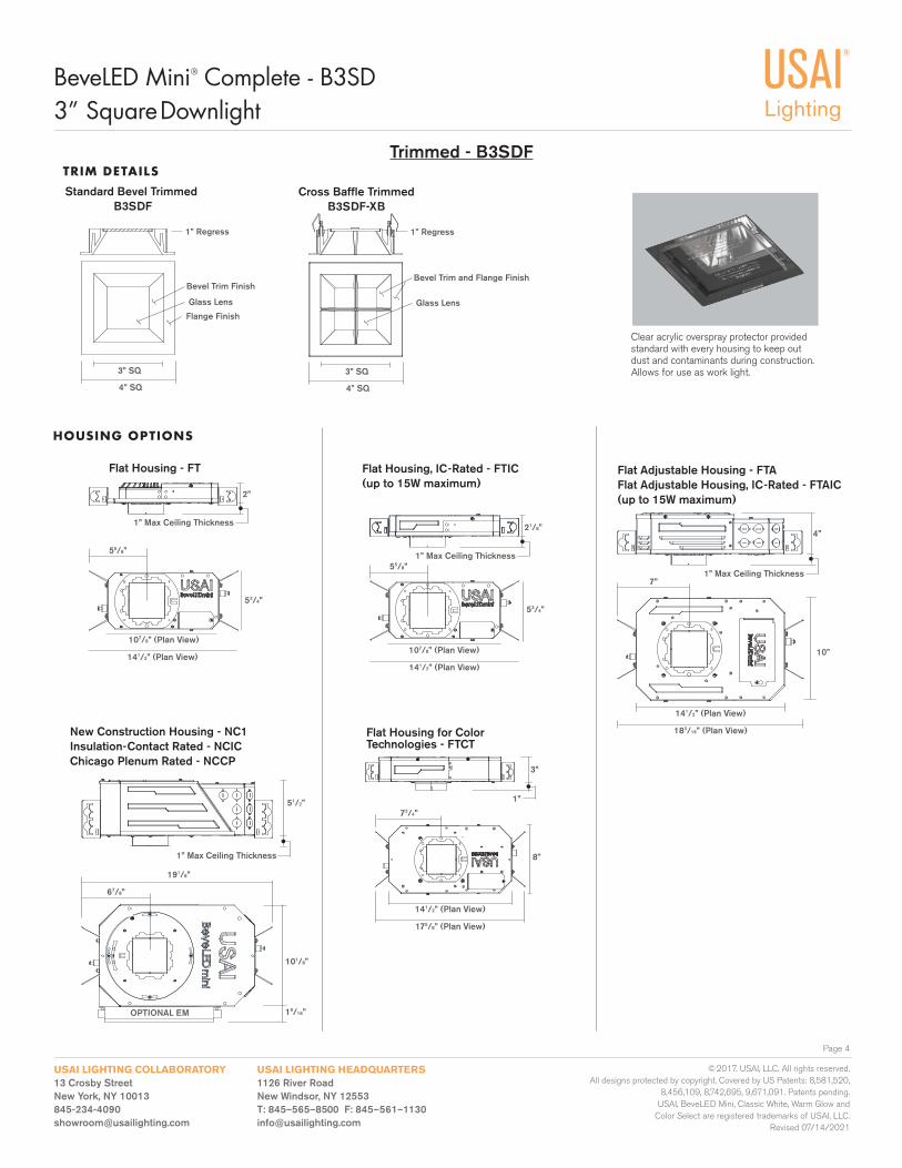
Clear acrylic overspray protector provided standard with every housing to keep out dust and contaminants during construction. Allows for use as work light.
Trimmed - B3SDFTRIM DETAILS
Glass Lens
Standard Bevel Trimmed B3SDF
Flange Finish
Bevel Trim Finish
1” Regress
3” SQ
4” SQ
Cross Baffl e TrimmedB3SDF-XB
1” Regress
Glass Lens
Bevel Trim and Flange Finish
3” SQ
4” SQ
Flat Housing for Color Technologies - FTCT
8”
175/8” (Plan View)
141/2” (Plan View)
3”
1”
73/4”
HOUSING OPTIONS
Flat Housing, IC-Rated - FTIC(up to 15W maximum)
Flat Adjustable Housing - FTAFlat Adjustable Housing, IC-Rated - FTAIC(up to 15W maximum)
Flat Housing - FT
New Construction Housing - NC1Insulation-Contact Rated - NCICChicago Plenum Rated - NCCP
53/4”
141/2” (Plan View)
107/8” (Plan View)
2”
53/4”
141/2” (Plan View)
107/8” (Plan View)
21/8”
183/16” (Plan View)
141/2” (Plan View)
4”
7”1” Max Ceiling Thickness
10”
101/8”
51/2”
67/8”
191/8”
OPTIONAL EMOPTIONAL EM 19/16”OPTIONAL EM
1” Max Ceiling Thickness
1” Max Ceiling Thickness
1” Max Ceiling Thickness
55/8”
55/8”
Page 5
3” Square Downlight
USAI LIGHTING HEADQUARTERS1126 River RoadNew Windsor, NY 12553T: 845–565–8500 F: 845–561–[email protected]
USAI LIGHTING COLLABORATORY13 Crosby StreetNew York, NY [email protected]
BeveLED Mini® Complete - B3SD
© 2017. USAI, LLC. All rights reserved. All designs protected by copyright. Covered by US Patents: 8,581,520,
8,456,109, 8,742,695, 9,671,091. Patents pending. USAI, BeveLED Mini, Classic White, Warm Glow and
Color Select are registered trademarks of USAI, LLC.Revised 07/14/2021
Flat Housing for Color Technologies - FTCT
8”
175/8” (Plan View)
141/2” (Plan View)
3”
1”
73/4”
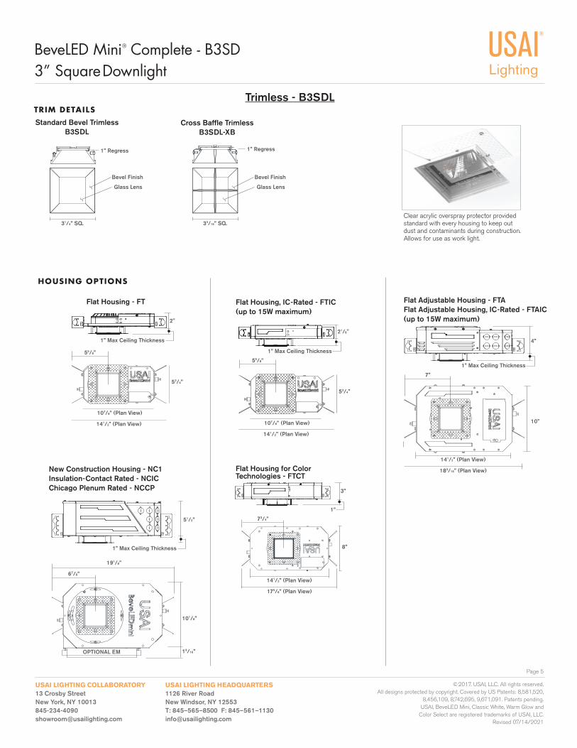
Clear acrylic overspray protector provided standard with every housing to keep out dust and contaminants during construction. Allows for use as work light.
Trimless - B3SDL
Standard Bevel TrimlessB3SDL
Glass Lens
TRIM DETAILS
Bevel Finish
1” Regress
31/4” SQ.
Cross Baffl e TrimlessB3SDL-XB
Glass Lens
Bevel Finish
1” Regress
33/16” SQ.
Flat Housing, IC-Rated - FTIC(up to 15W maximum)
Flat Adjustable Housing - FTAFlat Adjustable Housing, IC-Rated - FTAIC(up to 15W maximum)
New Construction Housing - NC1Insulation-Contact Rated - NCICChicago Plenum Rated - NCCP
53/4”
141/2” (Plan View)
107/8” (Plan View)
2"
21/8"
53/4”
141/2” (Plan View)
107/8” (Plan View)
4”
7”
1” Max Ceiling Thickness
183/16” (Plan View)
141/2” (Plan View)
10”
101/8”
51/2”
67/8”
191/8”
19/16”
1” Max Ceiling Thickness
1” Max Ceiling Thickness
1” Max Ceiling Thickness
HOUSING OPTIONS
Flat Housing - FT
OPTIONAL EMOPTIONAL EMOPTIONAL EM
55/8”55/8”
Page 6
3” Square Downlight
USAI LIGHTING HEADQUARTERS1126 River RoadNew Windsor, NY 12553T: 845–565–8500 F: 845–561–[email protected]
USAI LIGHTING COLLABORATORY13 Crosby StreetNew York, NY [email protected]
BeveLED Mini® Complete - B3SD
© 2017. USAI, LLC. All rights reserved. All designs protected by copyright. Covered by US Patents: 8,581,520,
8,456,109, 8,742,695, 9,671,091. Patents pending. USAI, BeveLED Mini, Classic White, Warm Glow and
Color Select are registered trademarks of USAI, LLC.Revised 07/14/2021
Flat Housing for Color Technologies - FTCT
8”
175/8” (Plan View)
141/2” (Plan View)
3”
11/8” 73/4”
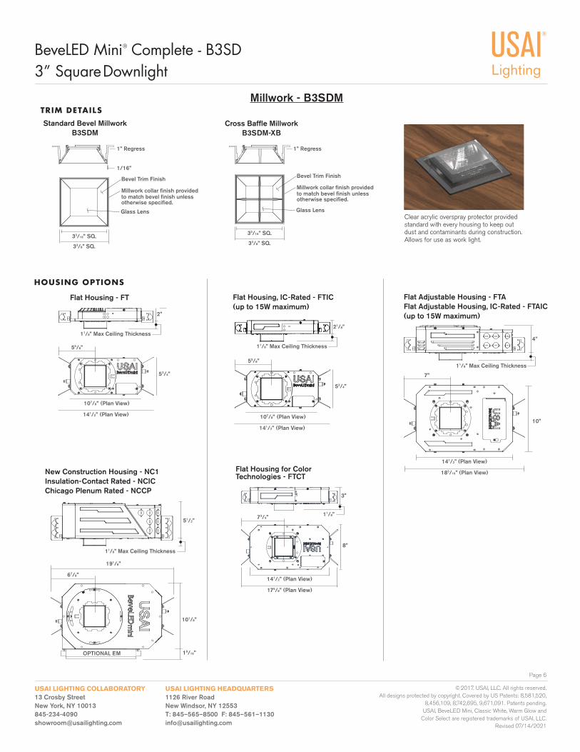
Clear acrylic overspray protector provided standard with every housing to keep out dust and contaminants during construction. Allows for use as work light.
Bevel Trim Finish
Glass Lens
Millwork collar fi nish provided to match bevel fi nish unless otherwise specifi ed.
1” Regress
1/16”
33/16” SQ.
33/8” SQ.
Millwork - B3SDMTRIM DETAILS
Standard Bevel Millwork B3SDM
Cross Baffl e MillworkB3SDM-XB
1” Regress
Bevel Trim Finish
Glass Lens
Millwork collar fi nish provided to match bevel fi nish unless otherwise specifi ed.
33/16” SQ.
33/8” SQ.
Flat Housing, IC-Rated - FTIC(up to 15W maximum)
Flat Adjustable Housing - FTAFlat Adjustable Housing, IC-Rated - FTAIC(up to 15W maximum)
New Construction Housing - NC1Insulation-Contact Rated - NCICChicago Plenum Rated - NCCP
53/4”
141/2” (Plan View)
107/8” (Plan View)
2”
4”
7”
11/8” Max Ceiling Thickness
183/16” (Plan View)
141/2” (Plan View)
10”
53/4”
141/2” (Plan View)
107/8” (Plan View)
21/8”
101/8”
51/2”
67/8”
191/8”
19/16”
11/8” Max Ceiling Thickness
11/8” Max Ceiling Thickness
11/8” Max Ceiling Thickness
HOUSING OPTIONS
Flat Housing - FT
55/8”
55/8”
OPTIONAL EMOPTIONAL EMOPTIONAL EM
BEVELED MINI SPECIFICATIONS
Page 7
3” Square Downlight
USAI LIGHTING HEADQUARTERS1126 River RoadNew Windsor, NY 12553T: 845–565–8500 F: 845–561–[email protected]
USAI LIGHTING COLLABORATORY13 Crosby StreetNew York, NY [email protected]
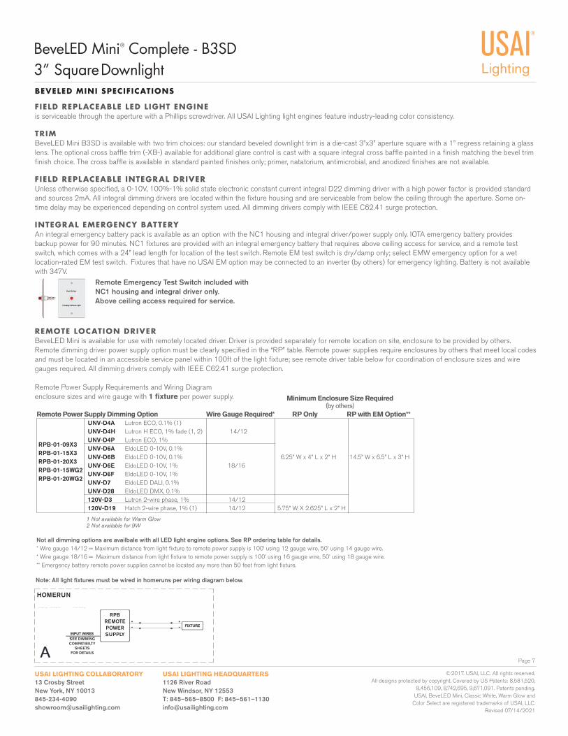
REMOTE LOCATION DRIVERBeveLED Mini is available for use with remotely located driver. Driver is provided separately for remote location on site, enclosure to be provided by others. Remote dimming driver power supply option must be clearly specifi ed in the “RP” table. Remote power supplies require enclosures by others that meet local codes and must be located in an accessible service panel within 100ft of the light fi xture; see remote driver table below for coordination of enclosure sizes and wire gauges required. All dimming drivers comply with IEEE C62.41 surge protection.
Remote Power Supply Requirements and Wiring Diagram enclosure sizes and wire gauge with 1 fi xture per power supply.
Not all dimming options are availbale with all LED light engine options. See RP ordering table for details.* Wire gauge 14/12 = Maximum distance from light fi xture to remote power supply is 100’ using 12 gauge wire, 50’ using 14 gauge wire. * Wire gauge 18/16 = Maximum distance from light fi xture to remote power supply is 100’ using 16 gauge wire, 50’ using 18 gauge wire. ** Emergency battery remote power supplies cannot be located any more than 50 feet from light fi xture.
Remote Power Supply Dimming Option Wire Gauge Required* RP Only RP with EM Option** UNV-D4A Lutron ECO, 0.1% (1) UNV-D4H Lutron H ECO, 1% fade (1, 2) 14/12 UNV-D4P Lutron ECO, 1% UNV-D6A EldoLED 0-10V, 0.1% UNV-D6B EldoLED 0-10V, 0.1% 6.25” W x 4” L x 2” H 14.5” W x 6.5” L x 3” H UNV-D6E EldoLED 0-10V, 1% 18/16 UNV-D6F EldoLED 0-10V, 1% UNV-D7 EldoLED DALI, 0.1% UNV-D28 EldoLED DMX, 0.1% 120V-D3 Lutron 2-wire phase, 1% 14/12 120V-D19 Hatch 2-wire phase, 1% (1) 14/12 5.75” W X 2.625” L x 2” H
Minimum Enclosure Size Required (by others)
Note: All light fi xtures must be wired in homeruns per wiring diagram below.
RPRP2REMOTEREMOTEPOWEPOWERSUPPLYSUPPLY
-
A
+
INPUT WIREINPUT WIRES
-+
USE FOR WIRING FIXTURESUSE FOR WIRING FIXTURESMDF0MDF02M2M DP02DP02MDF0MDF04M4M DP04DP04MDF0MDF06M6M DP06DP06MDF0MDF08M8M DP08DP08
FIXTURFIXTURE
SEE DIMMING COMPSEE DIMMING COMPATIBILITATIBILITYSHEET FOR SHEET FOR DETAILDETAILSSEE DIMMING
COMPATIBILTY SHEETS
FOR DETAILS
HOMERUN
RPBREMOTEPOWERSUPPLY
RPB-01-09X3RPB-01-15X3RPB-01-20X3RPB-01-15WG2RPB-01-20WG2
BeveLED Mini® Complete - B3SD
© 2017. USAI, LLC. All rights reserved. All designs protected by copyright. Covered by US Patents: 8,581,520,
8,456,109, 8,742,695, 9,671,091. Patents pending. USAI, BeveLED Mini, Classic White, Warm Glow and
Color Select are registered trademarks of USAI, LLC.Revised 07/14/2021
1 Not available for Warm Glow 2 Not available for 9W
Remote Emergency Test Switch included with NC1 housing and integral driver only. Above ceiling access required for service.
FIELD REPLACEABLE LED LIGHT ENGINEis serviceable through the aperture with a Phillips screwdriver. All USAI Lighting light engines feature industry-leading color consistency.
TRIMBeveLED Mini B3SD is available with two trim choices: our standard beveled downlight trim is a die-cast 3”x3” aperture square with a 1” regress retaining a glass lens. The optional cross baffl e trim (-XB-) available for additional glare control is cast with a square integral cross baffl e painted in a fi nish matching the bevel trim fi nish choice. The cross baffl e is available in standard painted fi nishes only; primer, natatorium, antimicrobial, and anodized fi nishes are not available.
FIELD REPLACEABLE INTEGRAL DRIVER Unless otherwise specifi ed, a 0-10V, 100%-1% solid state electronic constant current integral D22 dimming driver with a high power factor is provided standard and sources 2mA. All integral dimming drivers are located within the fi xture housing and are serviceable from below the ceiling through the aperture. Some on-time delay may be experienced depending on control system used. All dimming drivers comply with IEEE C62.41 surge protection.
INTEGRAL EMERGENCY BATTERYAn integral emergency battery pack is available as an option with the NC1 housing and integral driver/power supply only. IOTA emergency battery provides backup power for 90 minutes. NC1 fi xtures are provided with an integral emergency battery that requires above ceiling access for service, and a remote test switch, which comes with a 24” lead length for location of the test switch. Remote EM test switch is dry/damp only; select EMW emergency option for a wet location-rated EM test switch. Fixtures that have no USAI EM option may be connected to an inverter (by others) for emergency lighting. Battery is not available with 347V.
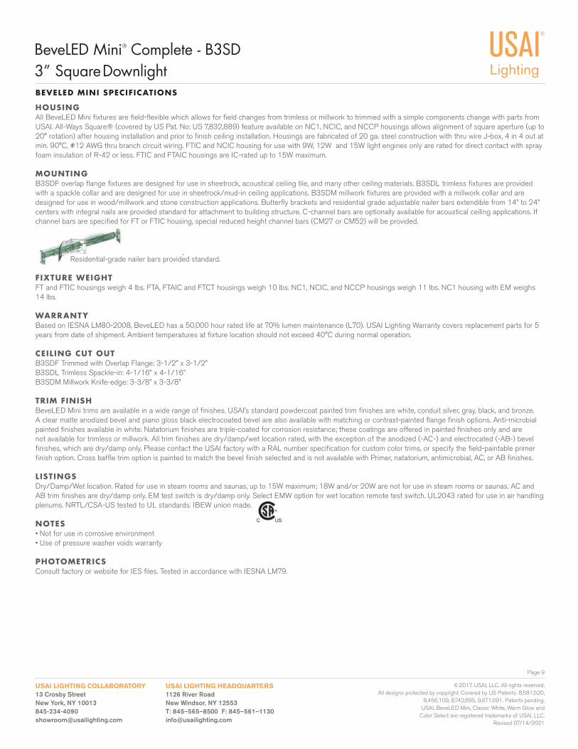
HOUSING All BeveLED Mini fi xtures are fi eld-fl exible which allows for fi eld changes from trimless or millwork to trimmed with a simple components change with parts from USAI. All-Ways Square® (covered by US Pat. No: US 7,832,889) feature available on NC1, NCIC, and NCCP housings allows alignment of square aperture (up to 20° rotation) after housing installation and prior to fi nish ceiling installation. Housings are fabricated of 20 ga. steel construction with thru wire J-box, 4 in 4 out at min. 90°C, #12 AWG thru branch circuit wiring. FTIC and NCIC housing for use with 9W, 12W and 15W light engines only are rated for direct contact with spray foam insulation of R-42 or less. FTIC and FTAIC housings are IC-rated up to 15W maximum.
MOUNTINGB3SDF overlap fl ange fi xtures are designed for use in sheetrock, acoustical ceiling tile, and many other ceiling materials. B3SDL trimless fi xtures are provided with a spackle collar and are designed for use in sheetrock/mud-in ceiling applications. B3SDM millwork fi xtures are provided with a millwork collar and are designed for use in wood/millwork and stone construction applications. Butterfl y brackets and residential grade adjustable nailer bars extendible from 14” to 24” centers with integral nails are provided standard for attachment to building structure. C-channel bars are optionally available for acoustical ceiling applications. If channel bars are specifi ed for FT or FTIC housing, special reduced height channel bars (CM27 or CM52) will be provided.
Residential-grade nailer bars provided standard.
FIXTURE WEIGHT FT and FTIC housings weigh 4 lbs. FTA, FTAIC and FTCT housings weigh 10 lbs. NC1, NCIC, and NCCP housings weigh 11 lbs. NC1 housing with EM weighs 14 lbs.
WARRANTYBased on IESNA LM80-2008, BeveLED has a 50,000 hour rated life at 70% lumen maintenance (L70). USAI Lighting Warranty covers replacement parts for 5 years from date of shipment. Ambient temperatures at fi xture location should not exceed 40°C during normal operation.
CEILING CUT OUTB3SDF Trimmed with Overlap Flange: 3-1/2” x 3-1/2”B3SDL Trimless Spackle-in: 4-1/16” x 4-1/16”B3SDM Millwork Knife-edge: 3-3/8” x 3-3/8”
TRIM FINISHBeveLED Mini trims are available in a wide range of fi nishes. USAI’s standard powdercoat painted trim fi nishes are white, conduit silver, gray, black, and bronze. A clear matte anodized bevel and piano gloss black electrocoated bevel are also available with matching or contrast-painted fl ange fi nish options. Anti-microbial painted fi nishes available in white. Natatorium fi nishes are triple-coated for corrosion resistance; these coatings are offered in painted fi nishes only and are not available for trimless or millwork. All trim fi nishes are dry/damp/wet location rated, with the exception of the anodized (-AC-) and electrocated (-AB-) bevel fi nishes, which are dry/damp only. Please contact the USAI factory with a RAL number specifi cation for custom color trims, or specify the fi eld-paintable primer fi nish option. Cross baffl e trim option is painted to match the bevel fi nish selected and is not available with Primer, natatorium, antimicrobial, AC, or AB fi nishes.
LISTINGS Dry/Damp/Wet location. Rated for use in steam rooms and saunas, up to 15W maximum; 18W and/or 20W are not for use in steam rooms or saunas. AC and AB trim fi nishes are dry/damp only. EM test switch is dry/damp only. Select EMW option for wet location remote test switch. UL2043 rated for use in air handling plenums. NRTL/CSA-US tested to UL standards. IBEW union made.
NOTES• Not for use in corrosive environment• Use of pressure washer voids warranty
PHOTOMETRICS Consult factory or website for IES fi les. Tested in accordance with IESNA LM79.
BEVELED MINI SPECIFICATIONS
Page 9
BeveLED Mini® Complete - B3SD3” Square Downlight
USAI LIGHTING HEADQUARTERS1126 River RoadNew Windsor, NY 12553T: 845–565–8500 F: 845–561–[email protected]
USAI LIGHTING COLLABORATORY13 Crosby StreetNew York, NY [email protected]
© 2017. USAI, LLC. All rights reserved. All designs protected by copyright. Covered by US Patents: 8,581,520,
8,456,109, 8,742,695, 9,671,091. Patents pending. USAI, BeveLED Mini, Classic White, Warm Glow and
Color Select are registered trademarks of USAI, LLC.Revised 07/14/2021
LED COLOR OPTIONS
Page 10
BeveLED Mini® Complete - B3SD3” Square Downlight
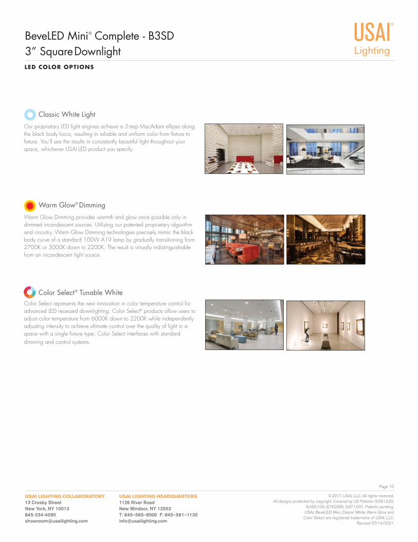
Warm Glow Dimming provides warmth and glow once possible only in dimmed incandescent sources. Utilizing our patented proprietary algorithm and circuitry, Warm Glow Dimming technologies precisely mimic the black body curve of a standard 100W A19 lamp by gradually transitioning from 2700K or 3000K down to 2200K. The result is virtually indistinguishable from an incandescent light source.
Warm Glow® Dimming
Color Select represents the next innovation in color temperature control for advanced LED recessed downlighting. Color Select® products allow users to adjust color temperature from 6000K down to 2200K while independently adjusting intensity to achieve ultimate control over the quality of light in a space with a single fi xture type. Color Select interfaces with standard dimming and control systems.
Color Select® Tunable White
Our proprietary LED light engines achieve a 2-step MacAdam ellipse along the black body locus, resulting in reliable and uniform color from fi xture to fi xture. You’ll see the results in consistently beautiful light throughout your space, whichever USAI LED product you specify.
Classic White Light
USAI LIGHTING HEADQUARTERS1126 River RoadNew Windsor, NY 12553T: 845–565–8500 F: 845–561–[email protected]
USAI LIGHTING COLLABORATORY13 Crosby StreetNew York, NY [email protected]
© 2017. USAI, LLC. All rights reserved. All designs protected by copyright. Covered by US Patents: 8,581,520,
8,456,109, 8,742,695, 9,671,091. Patents pending. USAI, BeveLED Mini, Classic White, Warm Glow and
Color Select are registered trademarks of USAI, LLC.Revised 07/14/2021
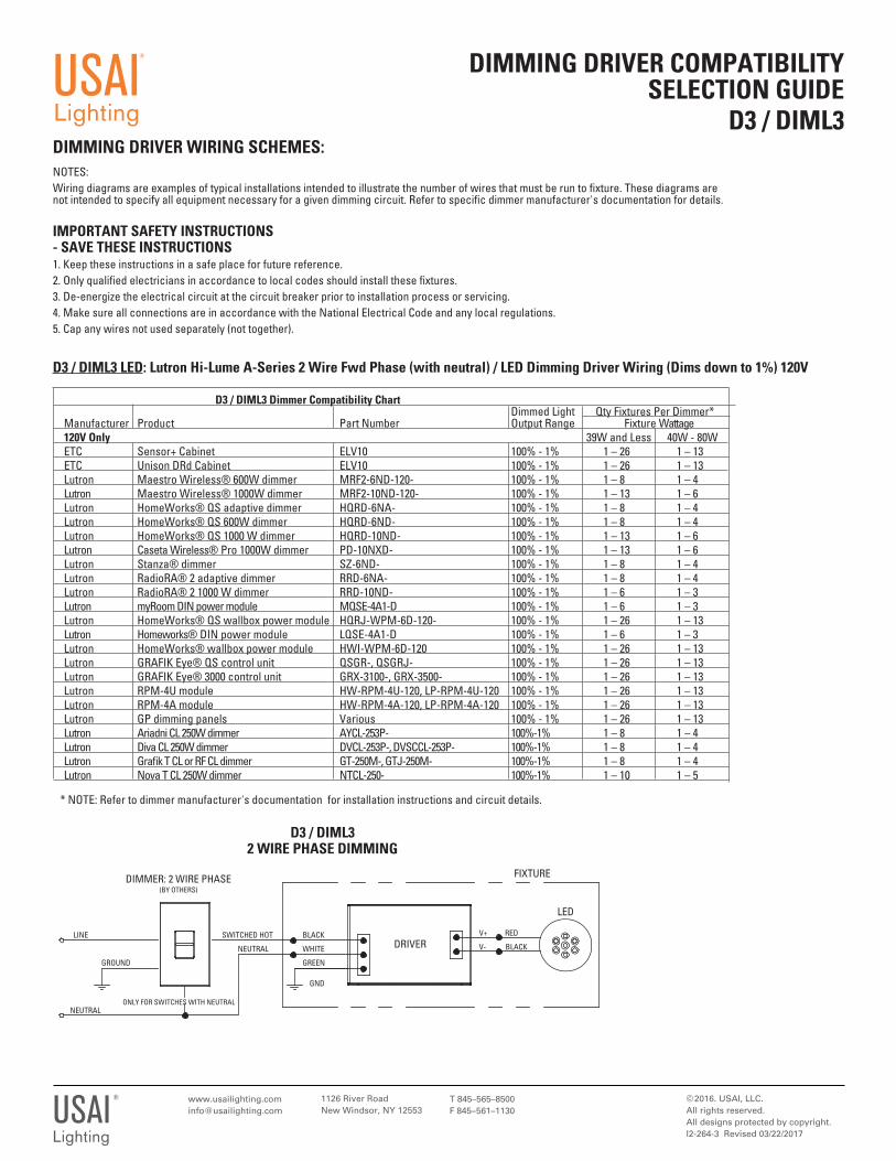
DIMMING DRIVER WIRING SCHEMES:
DIMMING DRIVER COMPATIBILITY SELECTION GUIDE
D3 / DIML3
1126 River RoadNew Windsor, NY 12553
© 2016. USAI, LLC.All rights reserved. All designs protected by copyright.I2-264-3 Revised 03/22/2017
T 845–565–8500F 845–561–1130USAI
®
Lighting
D3 / DIML3 LED: Lutron Hi-Lume A-Series 2 Wire Fwd Phase (with neutral) / LED Dimming Driver Wiring (Dims down to 1%) 120V
USAI®
Lighting
D3 / DIML3 Dimmer Compatibility Chart Dimmed Light Qty Fixtures Per Dimmer* Manufacturer Product Part Number Output Range Fixture Wattage 120V Only 39W and Less 40W - 80W ETC Sensor+ Cabinet ELV10 100% - 1% 1 – 26 1 – 13 ETC Unison DRd Cabinet ELV10 100% - 1% 1 – 26 1 – 13 Lutron Maestro Wireless® 600W dimmer MRF2-6ND-120- 100% - 1% 1 – 8 1 – 4 Lutron Maestro Wireless® 1000W dimmer MRF2-10ND-120- 100% - 1% 1 – 13 1 – 6 Lutron HomeWorks® QS adaptive dimmer HQRD-6NA- 100% - 1% 1 – 8 1 – 4 Lutron HomeWorks® QS 600W dimmer HQRD-6ND- 100% - 1% 1 – 8 1 – 4 Lutron HomeWorks® QS 1000 W dimmer HQRD-10ND- 100% - 1% 1 – 13 1 – 6 Lutron Caseta Wireless® Pro 1000W dimmer PD-10NXD- 100% - 1% 1 – 13 1 – 6 Lutron Stanza® dimmer SZ-6ND- 100% - 1% 1 – 8 1 – 4 Lutron RadioRA® 2 adaptive dimmer RRD-6NA- 100% - 1% 1 – 8 1 – 4 Lutron RadioRA® 2 1000 W dimmer RRD-10ND- 100% - 1% 1 – 6 1 – 3 Lutron myRoom DIN power module MQSE-4A1-D 100% - 1% 1 – 6 1 – 3 Lutron HomeWorks® QS wallbox power module HQRJ-WPM-6D-120- 100% - 1% 1 – 26 1 – 13 Lutron Homeworks® DIN power module LQSE-4A1-D 100% - 1% 1 – 6 1 – 3 Lutron HomeWorks® wallbox power module HWI-WPM-6D-120 100% - 1% 1 – 26 1 – 13 Lutron GRAFIK Eye® QS control unit QSGR-, QSGRJ- 100% - 1% 1 – 26 1 – 13 Lutron GRAFIK Eye® 3000 control unit GRX-3100-, GRX-3500- 100% - 1% 1 – 26 1 – 13 Lutron RPM-4U module HW-RPM-4U-120, LP-RPM-4U-120 100% - 1% 1 – 26 1 – 13 Lutron RPM-4A module HW-RPM-4A-120, LP-RPM-4A-120 100% - 1% 1 – 26 1 – 13 Lutron GP dimming panels Various 100% - 1% 1 – 26 1 – 13 Lutron Ariadni CL 250W dimmer AYCL-253P- 100%-1% 1 – 8 1 – 4 Lutron Diva CL 250W dimmer DVCL-253P-, DVSCCL-253P- 100%-1% 1 – 8 1 – 4 Lutron Grafi k T CL or RF CL dimmer GT-250M-, GTJ-250M- 100%-1% 1 – 8 1 – 4 Lutron Nova T CL 250W dimmer NTCL-250- 100%-1% 1 – 10 1 – 5
* NOTE: Refer to dimmer manufacturer's documentation for installation instructions and circuit details.
LED
SWITCHED HOT
NEUTRAL
D3 / DIML3 2 WIRE PHASE DIMMING
DIMMER: 2 WIRE PHASE(BY OTHERS)
BLACK
WHITE
GREEN
GND
V+ RED
V- BLACK
FIXTURE
DRIVER
NEUTRAL
LINE
GROUND
ONLY FOR SWITCHES WITH NEUTRAL
NOTES: Wiring diagrams are examples of typical installations intended to illustrate the number of wires that must be run to fi xture. These diagrams are not intended to specify all equipment necessary for a given dimming circuit. Refer to specifi c dimmer manufacturer's documentation for details.
IMPORTANT SAFETY INSTRUCTIONS - SAVE THESE INSTRUCTIONS1. Keep these instructions in a safe place for future reference. 2. Only qualifi ed electricians in accordance to local codes should install these fi xtures.3. De-energize the electrical circuit at the circuit breaker prior to installation process or servicing.4. Make sure all connections are in accordance with the National Electrical Code and any local regulations.5. Cap any wires not used separately (not together).
1126 River RoadNew Windsor, NY 12553
© 2019. USAI, LLC.All rights reserved. All designs protected by copyright.I2-264-4AP
T 845–565–8500F 845–561–1130USAI
®
Lighting
DIMMING DRIVER COMPATIBILITY SELECTION GUIDE
D4A / DIML4A and D4P / DIML4PDIMMING DRIVER WIRING SCHEMES:
USAI®
Lighting
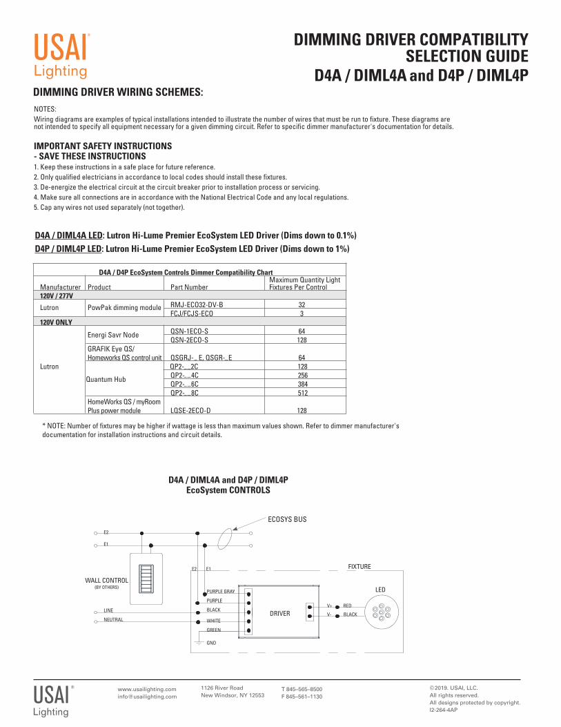
D4A / DIML4A LED: Lutron Hi-Lume Premier EcoSystem LED Driver (Dims down to 0.1%)
LED
D4A / DIML4A and D4P / DIML4P EcoSystem CONTROLS
PURPLE GRAY
PURPLE
BLACK
WHITE
GREEN
GND
V+ RED
V- BLACK
FIXTURE
DRIVER
WALL CONTROL(BY OTHERS)
LINE
NEUTRAL
E2
E1
E1
ECOSYS BUS
E2
D4A / D4P EcoSystem Controls Dimmer Compatibility Chart Maximum Quantity Light Manufacturer Product Part Number Fixtures Per Control 120V / 277V Lutron PowPak dimming module RMJ-ECO32-DV-B 32 FCJ/FCJS-ECO 3 120V ONLY Energi Savr Node QSN-1ECO-S 64 QSN-2ECO-S 128 GRAFIK Eye QS/ Homeworks QS control unit QSGRJ- E, QSGR- E 64 Lutron
Quantum Hub
QP2- 2C 128 QP2- 4C 256 QP2- 6C 384 QP2- 8C 512 HomeWorks QS / myRoom Plus power module LQSE-2ECO-D 128
D4P / DIML4P LED: Lutron Hi-Lume Premier EcoSystem LED Driver (Dims down to 1%)
* NOTE: Number of fixtures may be higher if wattage is less than maximum values shown. Refer to dimmer manufacturer's documentation for installation instructions and circuit details.
NOTES: Wiring diagrams are examples of typical installations intended to illustrate the number of wires that must be run to fixture. These diagrams are not intended to specify all equipment necessary for a given dimming circuit. Refer to specific dimmer manufacturer's documentation for details.
IMPORTANT SAFETY INSTRUCTIONS - SAVE THESE INSTRUCTIONS1. Keep these instructions in a safe place for future reference. 2. Only qualified electricians in accordance to local codes should install these fixtures.3. De-energize the electrical circuit at the circuit breaker prior to installation process or servicing.4. Make sure all connections are in accordance with the National Electrical Code and any local regulations.5. Cap any wires not used separately (not together).
1126 River RoadNew Windsor, NY 12553
© 2016. USAI, LLC.All rights reserved. All designs protected by copyright.I2-264-4H Revised 04/09/2021
T 845–565–8500F 845–561–1130USAI
®
Lighting
DIMMING DRIVER COMPATIBILITY SELECTION GUIDE
D4H /DIML4HDIMMING DRIVER WIRING SCHEMES:
USAI®
Lighting
LED
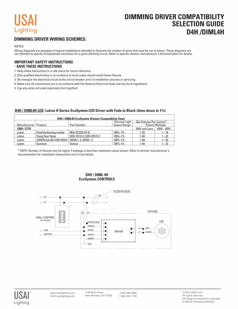
D4H / DIML 4H EcoSystem CONTROLS
PURPLE GRAY
PURPLE
BLACK
WHITE
GREEN
GND
V+ RED
V- BLACK
FIXTURE
DRIVER
WALL CONTROL(BY OTHERS)
LINE
NEUTRAL
E2
E1
E1
ECOSYS BUS
E2
D4H / DIML4H EcoSystem Dimmer Compatibility Chart Dimmed Light Qty Fixtures Per Control* Manufacturer Product Part Number Output Range Fixture Wattage 120V / 277V 39W and Less 40W - 80W Lutron PowPak dimming module RMJ-ECO32-DV-B 100%–1% 1–32 1 – 16 Lutron Energi Savr Node QSN-1ECO-S, QSN-2ECO-S 100%–1% 1–64 1 – 32 Lutron GRAFIK Eye QS (120V ONLY) QSGRJ-_E, QSGR-_E 100%–1% 1–64 1 – 32 Lutron Quantum Various 100%–1% 1–64 1 – 32
D4H / DIML4H LED: Lutron H Series EcoSystem LED Driver with Fade to Black (dims down to 1%)
* NOTE: Number of fixtures may be higher if wattage is less than maximum values shown. Refer to dimmer manufacturer's documentation for installation instructions and circuit details.
NOTES: Wiring diagrams are examples of typical installations intended to illustrate the number of wires that must be run to fixture. These diagrams are not intended to specify all equipment necessary for a given dimming circuit. Refer to specific dimmer manufacturer's documentation for details.
IMPORTANT SAFETY INSTRUCTIONS - SAVE THESE INSTRUCTIONS1. Keep these instructions in a safe place for future reference. 2. Only qualified electricians in accordance to local codes should install these fixtures.3. De-energize the electrical circuit at the circuit breaker prior to installation process or servicing.4. Make sure all connections are in accordance with the National Electrical Code and any local regulations.5. Cap any wires not used separately (not together).
© 2016. USAI, LLC.All rights reserved. All designs protected by copyright.I2-264-6 Revised 08/16/2019
DIMMING DRIVER COMPATIBILITY SELECTION GUIDE
D6A / DIML6A and D6E / DIML6ED6B / DIML6B and D6F / DIML6F
DIMMING DRIVER WIRING SCHEMES:
USAI®
LightingIMPORTANT SAFETY INSTRUCTIONS - SAVE THESE INSTRUCTIONS1. Keep these instructions in a safe place for future reference. 2. Only qualified electricians in accordance to local codes should install these fixtures.3. De-energize the electrical circuit at the circuit breaker prior to installation process or servicing.4. Make sure all connections are in accordance with the National Electrical Code and any local regulations.5. Cap any wires not used separately (not together).
LED0-10V (-)
0-10V (+)
SWITCHED HOT
NEUTRAL
D6 / DIML60-10V DIMMING W/RELAY TO SWITCH POWER
DIMMER: 0-10V
GRAY
PURPLE
BLACK
WHITE
GREEN
GND
FIXTURE
DRIVER
LINE
NEUTRAL
CLASS 2 CONTROL WIRES
RELAY (BY OTHERS)
DIML6A, 6B 0-10V DIMMING (NO RELAY)
DIMMER: 0-10V w/POWER SWITCHING
(BY OTHERS)
FIXTURE
V+ RED
V- BLACK
USAI®
Lighting
1126 River RoadNew Windsor, NY 12553
V+ RED
V- BLACK
LED0-10V (-)
0-10V (+)
SWITCHED HOT
NEUTRAL
D6 / DIML60-10V DIMMING (NO RELAY)
DIMMER: 0-10V w/POWER SWITCHING
(BY OTHERS)
GRAY
PURPLE
BLACK
WHITE
GREEN
GND
FIXTURE
DRIVERLINE
GROUND
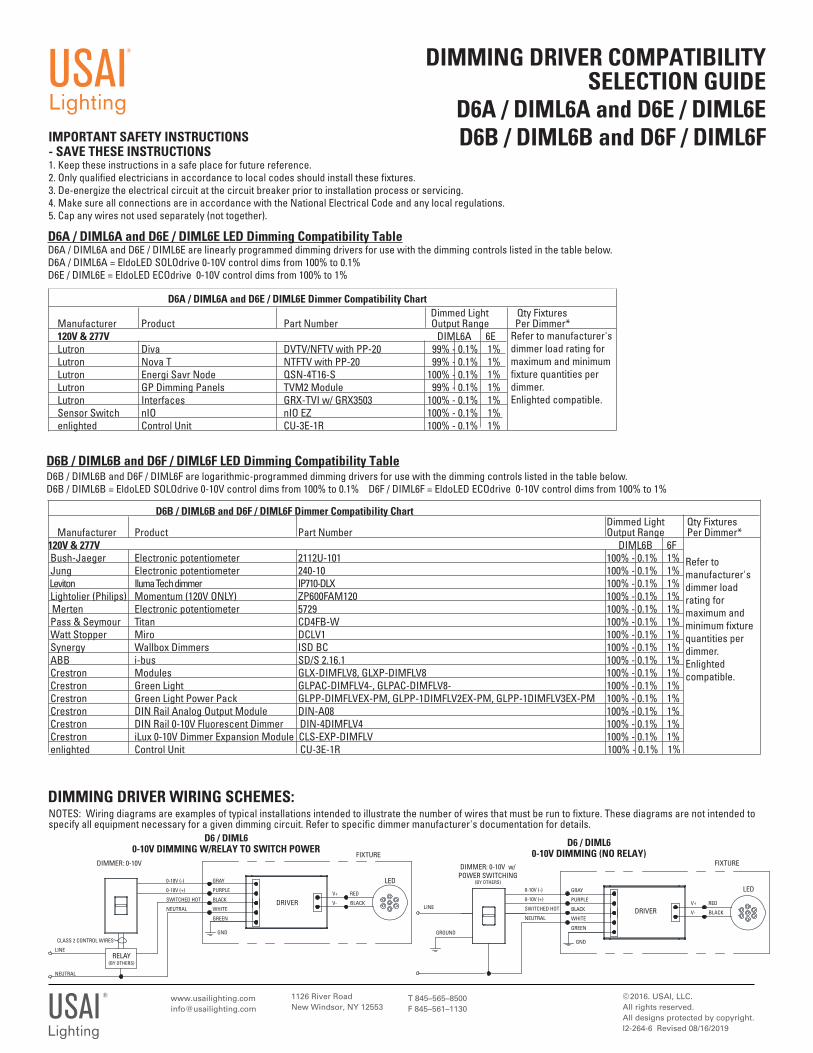
D6A / DIML6A and D6E / DIML6E LED Dimming Compatibility TableD6A / DIML6A and D6E / DIML6E are linearly programmed dimming drivers for use with the dimming controls listed in the table below.D6A / DIML6A = EldoLED SOLOdrive 0-10V control dims from 100% to 0.1%D6E / DIML6E = EldoLED ECOdrive 0-10V control dims from 100% to 1%
T 845–565–8500F 845–561–1130
NOTES: Wiring diagrams are examples of typical installations intended to illustrate the number of wires that must be run to fixture. These diagrams are not intended to specify all equipment necessary for a given dimming circuit. Refer to specific dimmer manufacturer's documentation for details.
Dimmed Light Qty Fixtures Manufacturer Product Part Number Output Range Per Dimmer* 120V & 277V DIML6A 6E Lutron Diva DVTV/NFTV with PP-20 99% - 0.1% 1% Lutron Nova T NTFTV with PP-20 99% - 0.1% 1% Lutron Energi Savr Node QSN-4T16-S 100% - 0.1% 1% Lutron GP Dimming Panels TVM2 Module 99% - 0.1% 1% Lutron Interfaces GRX-TVI w/ GRX3503 100% - 0.1% 1% Sensor Switch nIO nIO EZ 100% - 0.1% 1% enlighted Control Unit CU-3E-1R 100% - 0.1% 1%
Refer to manufacturer's dimmer load rating for maximum and minimum fixture quantities per dimmer.Enlighted compatible.
D6A / DIML6A and D6E / DIML6E Dimmer Compatibility Chart
D6B / DIML6B and D6F / DIML6F LED Dimming Compatibility TableD6B / DIML6B and D6F / DIML6F are logarithmic-programmed dimming drivers for use with the dimming controls listed in the table below.D6B / DIML6B = EldoLED SOLOdrive 0-10V control dims from 100% to 0.1% D6F / DIML6F = EldoLED ECOdrive 0-10V control dims from 100% to 1%
D6B / DIML6B and D6F / DIML6F Dimmer Compatibility Chart Dimmed Light Qty Fixtures Manufacturer Product Part Number Output Range Per Dimmer* 120V & 277V DIML6B 6F Bush-Jaeger Electronic potentiometer 2112U-101 100% - 0.1% 1% Jung Electronic potentiometer 240-10 100% - 0.1% 1% Leviton Iluma Tech dimmer IP710-DLX 100% - 0.1% 1% Lightolier (Philips) Momentum (120V ONLY) ZP600FAM120 100% - 0.1% 1% Merten Electronic potentiometer 5729 100% - 0.1% 1% Pass & Seymour Titan CD4FB-W 100% - 0.1% 1% Watt Stopper Miro DCLV1 100% - 0.1% 1% Synergy Wallbox Dimmers ISD BC 100% - 0.1% 1% ABB i-bus SD/S 2.16.1 100% - 0.1% 1% Crestron Modules GLX-DIMFLV8, GLXP-DIMFLV8 100% - 0.1% 1% Crestron Green Light GLPAC-DIMFLV4-, GLPAC-DIMFLV8- 100% - 0.1% 1% Crestron Green Light Power Pack GLPP-DIMFLVEX-PM, GLPP-1DIMFLV2EX-PM, GLPP-1DIMFLV3EX-PM 100% - 0.1% 1% Crestron DIN Rail Analog Output Module DIN-A08 100% - 0.1% 1% Crestron DIN Rail 0-10V Fluorescent Dimmer DIN-4DIMFLV4 100% - 0.1% 1% Crestron iLux 0-10V Dimmer Expansion Module CLS-EXP-DIMFLV 100% - 0.1% 1% enlighted Control Unit CU-3E-1R 100% - 0.1% 1%
Refer to manufacturer's dimmer load rating for maximum and minimum fixture quantities per dimmer.Enlighted compatible.
1126 River RoadNew Windsor, NY 12553
© 2016. USAI, LLC.All rights reserved. All designs protected by copyright.I2-264-7 Revised 08/14/2017
T 845–565–8500F 845–561–1130USAI
®
Lighting
DIMMING DRIVER COMPATIBILITY SELECTION GUIDE
D7 / DIML7 and D7EDIMMING DRIVER WIRING SCHEMES:
USAI®
Lighting
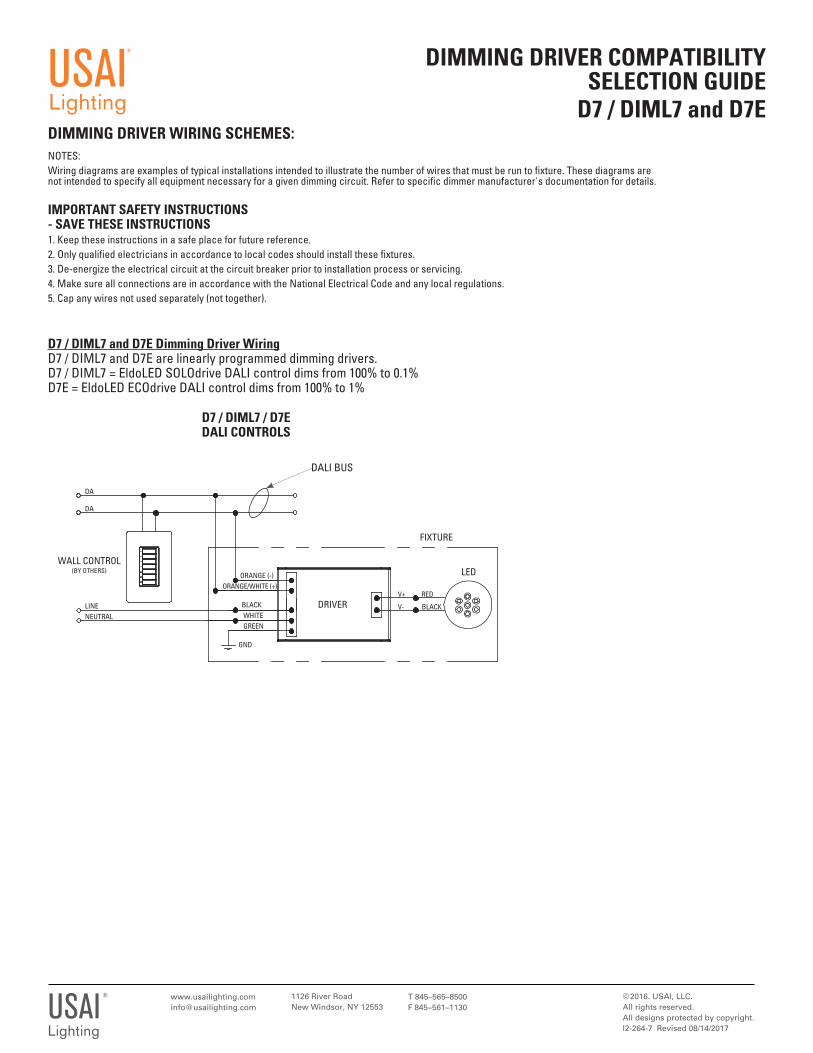
D7 / DIML7 and D7E Dimming Driver WiringD7 / DIML7 and D7E are linearly programmed dimming drivers. D7 / DIML7 = EldoLED SOLOdrive DALI control dims from 100% to 0.1%D7E = EldoLED ECOdrive DALI control dims from 100% to 1%
LED
D7 / DIML7 / D7EDALI CONTROLS
V+ RED
V- BLACK
FIXTURE
DRIVER
DALI BUS
WALL CONTROL(BY OTHERS)
LINENEUTRAL
DA
DA
ORANGE (-)ORANGE/WHITE (+)
BLACK WHITE GREEN
GND
NOTES: Wiring diagrams are examples of typical installations intended to illustrate the number of wires that must be run to fi xture. These diagrams are not intended to specify all equipment necessary for a given dimming circuit. Refer to specifi c dimmer manufacturer's documentation for details.
IMPORTANT SAFETY INSTRUCTIONS - SAVE THESE INSTRUCTIONS1. Keep these instructions in a safe place for future reference. 2. Only qualifi ed electricians in accordance to local codes should install these fi xtures.3. De-energize the electrical circuit at the circuit breaker prior to installation process or servicing.4. Make sure all connections are in accordance with the National Electrical Code and any local regulations.5. Cap any wires not used separately (not together).
DIMMING DRIVER WIRING SCHEMES:
DIMMING DRIVER COMPATIBILITY SELECTION GUIDE
D15 / DIML15USAI
®
Lighting
V+ RED
V- BLACK
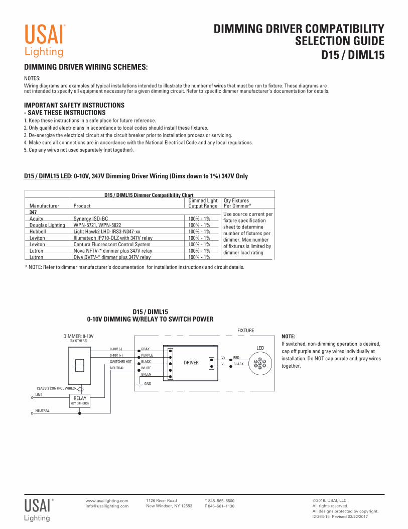
D15 / DIML15 LED: 0-10V, 347V Dimming Driver Wiring (Dims down to 1%) 347V Only
LED0-10V (-)
0-10V (+)
SWITCHED HOT
NEUTRAL
D15 / DIML15 0-10V DIMMING W/RELAY TO SWITCH POWER
D15 / DIML15 Dimmer Compatibility Chart Dimmed Light Qty Fixtures Manufacturer Product Output Range Per Dimmer* 347 Acuity Synergy ISD-BC 100% - 1% Douglas Lighting WPN-5721, WPN-5822 100% - 1% Hubbell Light Hawk2 LHD-IRS3-N347-xx 100% - 1% Leviton Illumatech IP710-DLZ with 347V relay 100% - 1% Leviton Centura Fluorescent Control System 100% - 1% Lutron Nova NFTV-* dimmer plus 347V relay 100% - 1% Lutron Diva DVTV-* dimmer plus 347V relay 100% - 1%
Use source current per fi xture specifi cation sheet to determine number of fi xtures per dimmer. Max number of fi xtures is limited by dimmer load rating.
* NOTE: Refer to dimmer manufacturer's documentation for installation instructions and circuit details.
DIMMER: 0-10V (BY OTHERS)
GRAY
PURPLE
BLACK
WHITE
GREEN
GND
V+ RED
V- BLACK
FIXTURE
DRIVER
LINE
NEUTRAL
CLASS 2 CONTROL WIRES
RELAY (BY OTHERS)
LED0-10V (-)
0-10V (+)
SWITCHED HOT
NEUTRAL
DIML2 0-10V DIMMING (NO RELAY)
DIMMER: 0-10V w/POWER SWITCHING
(BY OTHERS)
GRAY
PURPLE
BLACK
WHITE
GREEN
GND
FIXTURE
DRIVER
NEUTRAL
LINE
GROUND
NOTE:If switched, non-dimming operation is desired, cap off purple and gray wires individually at installation. Do NOT cap purple and gray wirestogether.
NOTE:Quickship fi xtures are shipped prewired for 0-10V dimming controls. If switched, non-dimming operation is desired, cap off purple and gray wires separately at installation. DoNOT cap purple and gray wires together.
1126 River RoadNew Windsor, NY 12553
© 2016. USAI, LLC.All rights reserved. All designs protected by copyright.I2-264-15 Revised 03/22/2017
T 845–565–8500F 845–561–1130USAI
®
Lighting
NOTES: Wiring diagrams are examples of typical installations intended to illustrate the number of wires that must be run to fi xture. These diagrams are not intended to specify all equipment necessary for a given dimming circuit. Refer to specifi c dimmer manufacturer's documentation for details.
IMPORTANT SAFETY INSTRUCTIONS - SAVE THESE INSTRUCTIONS1. Keep these instructions in a safe place for future reference. 2. Only qualifi ed electricians in accordance to local codes should install these fi xtures.3. De-energize the electrical circuit at the circuit breaker prior to installation process or servicing.4. Make sure all connections are in accordance with the National Electrical Code and any local regulations.5. Cap any wires not used separately (not together).
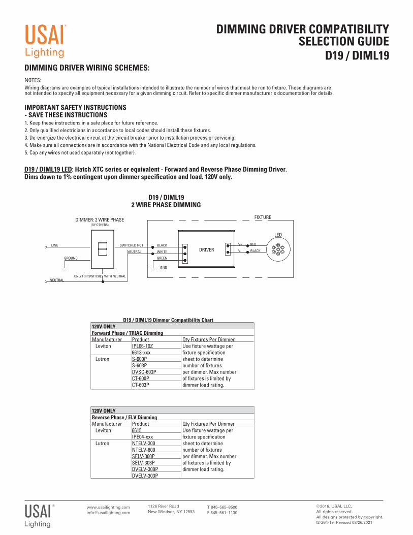
D19 / DIML19 LED: Hatch XTC series or equivalent - Forward and Reverse Phase Dimming Driver. Dims down to 1% contingent upon dimmer specifi cation and load. 120V only.
1126 River RoadNew Windsor, NY 12553
© 2016. USAI, LLC.All rights reserved. All designs protected by copyright.I2-264-19 Revised 03/26/2021
T 845–565–8500F 845–561–1130USAI
®
Lighting
DIMMING DRIVER COMPATIBILITY SELECTION GUIDE
D19 / DIML19DIMMING DRIVER WIRING SCHEMES:
USAI®
Lighting
LED
SWITCHED HOT
NEUTRAL
D19 / DIML192 WIRE PHASE DIMMING
DIMMER: 2 WIRE PHASE(BY OTHERS)
BLACK
WHITE
GREEN
GND
V+ RED
V- BLACK
FIXTURE
DRIVER
NEUTRAL
LINE
GROUND
ONLY FOR SWITCHES WITH NEUTRAL
NOTES: Wiring diagrams are examples of typical installations intended to illustrate the number of wires that must be run to fixture. These diagrams are not intended to specify all equipment necessary for a given dimming circuit. Refer to specific dimmer manufacturer's documentation for details.
IMPORTANT SAFETY INSTRUCTIONS - SAVE THESE INSTRUCTIONS1. Keep these instructions in a safe place for future reference. 2. Only qualified electricians in accordance to local codes should install these fixtures.3. De-energize the electrical circuit at the circuit breaker prior to installation process or servicing.4. Make sure all connections are in accordance with the National Electrical Code and any local regulations.5. Cap any wires not used separately (not together).
D19 / DIML19 Dimmer Compatibility Chart 120V ONLY Forward Phase / TRIAC Dimming Manufacturer Product Qty Fixtures Per Dimmer Leviton IPL06-10Z Use fixture wattage per 6613-xxx fixture specification Lutron S-600P sheet to determine S-603P number of fixtures DVSC-603P per dimmer. Max number CT-600P of fixtures is limited by CT-603P dimmer load rating.
120V ONLY Reverse Phase / ELV Dimming Manufacturer Product Qty Fixtures Per Dimmer Leviton 6615 Use fixture wattage per IPE04-xxx fixture specification Lutron NTELV-300 sheet to determine NTELV-600 number of fixtures SELV-300P per dimmer. Max number SELV-303P of fixtures is limited by DVELV-300P dimmer load rating. DVELV-303P
V+ RED
V- BLACK
DIMMING DRIVER WIRING SCHEMES:
DIMMING DRIVER COMPATIBILITY SELECTION GUIDE
D22
1126 River RoadNew Windsor, NY 12553
© 2019. USAI, LLC.All rights reserved. All designs protected by copyright.I2-264-22 Revised 12/18/2019
T 845–565–8500F 845–561–1130USAI
®
Lighting
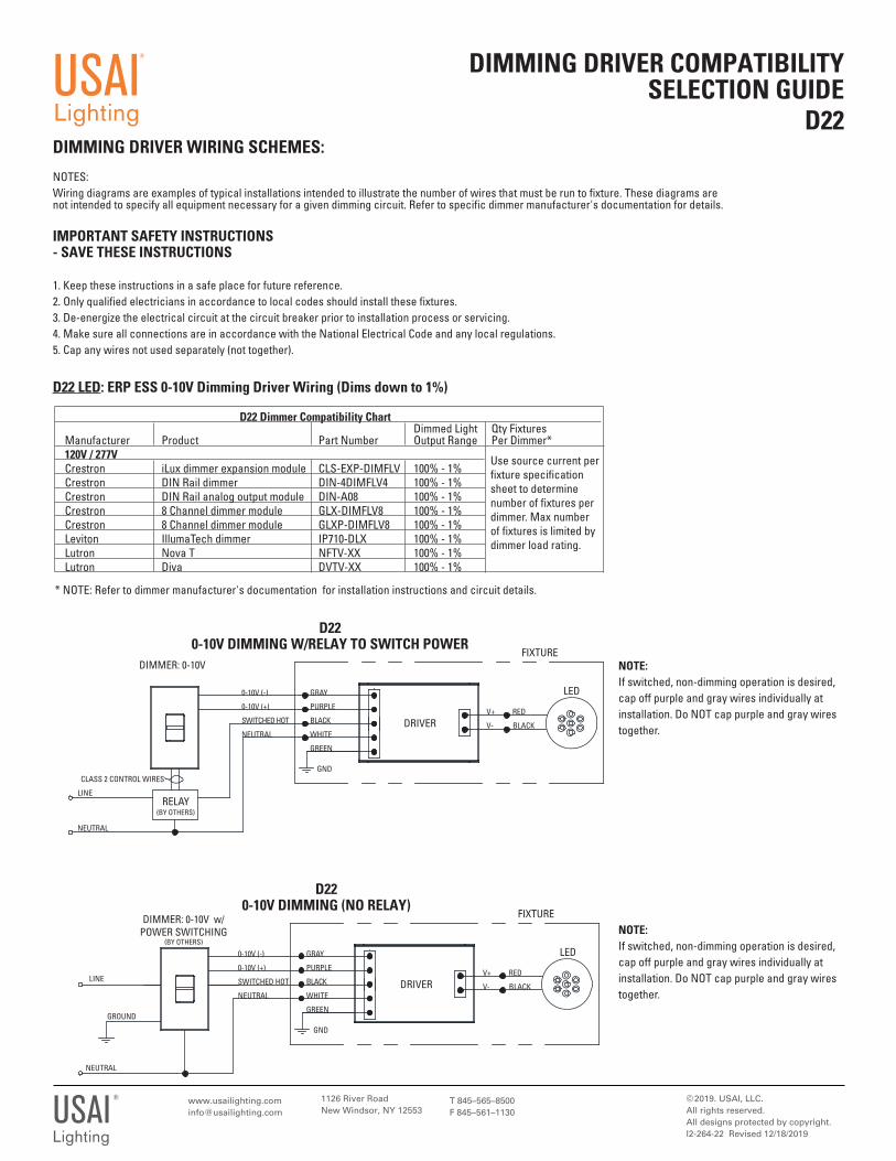
D22 LED: ERP ESS 0-10V Dimming Driver Wiring (Dims down to 1%)
LED0-10V (-)
0-10V (+)
SWITCHED HOT
NEUTRAL
USAI®
Lighting
D22 0-10V DIMMING W/RELAY TO SWITCH POWER
D22 Dimmer Compatibility Chart Dimmed Light Qty Fixtures Manufacturer Product Part Number Output Range Per Dimmer* 120V / 277V Crestron iLux dimmer expansion module CLS-EXP-DIMFLV 100% - 1% Crestron DIN Rail dimmer DIN-4DIMFLV4 100% - 1% Crestron DIN Rail analog output module DIN-A08 100% - 1% Crestron 8 Channel dimmer module GLX-DIMFLV8 100% - 1% Crestron 8 Channel dimmer module GLXP-DIMFLV8 100% - 1% Leviton IllumaTech dimmer IP710-DLX 100% - 1% Lutron Nova T NFTV-XX 100% - 1% Lutron Diva DVTV-XX 100% - 1%
Use source current per fixture specification sheet to determine number of fixtures per dimmer. Max number of fixtures is limited by dimmer load rating.
* NOTE: Refer to dimmer manufacturer's documentation for installation instructions and circuit details.
DIMMER: 0-10V
GRAY
PURPLE
BLACK
WHITE
GREEN
GND
V+ RED
V- BLACK
FIXTURE
DRIVER
LINE
NEUTRAL
CLASS 2 CONTROL WIRES
RELAY (BY OTHERS)
LED0-10V (-)
0-10V (+)
SWITCHED HOT
NEUTRAL
D22 0-10V DIMMING (NO RELAY)
DIMMER: 0-10V w/POWER SWITCHING
(BY OTHERS)
GRAY
PURPLE
BLACK
WHITE
GREEN
GND
FIXTURE
DRIVER
NEUTRAL
LINE
GROUND
NOTE:If switched, non-dimming operation is desired, cap off purple and gray wires individually at installation. Do NOT cap purple and gray wirestogether.
NOTE:If switched, non-dimming operation is desired, cap off purple and gray wires individually at installation. Do NOT cap purple and gray wirestogether.
NOTES: Wiring diagrams are examples of typical installations intended to illustrate the number of wires that must be run to fixture. These diagrams are not intended to specify all equipment necessary for a given dimming circuit. Refer to specific dimmer manufacturer's documentation for details.
IMPORTANT SAFETY INSTRUCTIONS - SAVE THESE INSTRUCTIONS
1. Keep these instructions in a safe place for future reference. 2. Only qualified electricians in accordance to local codes should install these fixtures.3. De-energize the electrical circuit at the circuit breaker prior to installation process or servicing.4. Make sure all connections are in accordance with the National Electrical Code and any local regulations.5. Cap any wires not used separately (not together).
1126 River RoadNew Windsor, NY 12553
© 2017. USAI, LLC.All rights reserved. All designs protected by copyright.I2-264-22 Revised 12/18/2019
T 845–565–8500F 845–561–1130USAI
®
Lighting
DIMMING DRIVER COMPATIBILITY SELECTION GUIDE
D22 ContinuedDIMMING DRIVER WIRING SCHEMES:
USAI®
Lighting
NOTES: Wiring diagrams are examples of typical installations intended to illustrate the number of wires that must be run to fixture. These diagrams are not intended to specify all equipment necessary for a given dimming circuit. Refer to specific dimmer manufacturer's documentation for details.
IMPORTANT SAFETY INSTRUCTIONS - SAVE THESE INSTRUCTIONS1. Keep these instructions in a safe place for future reference. 2. Only qualified electricians in accordance to local codes should install these fixtures.3. De-energize the electrical circuit at the circuit breaker prior to installation process or servicing.4. Make sure all connections are in accordance with the National Electrical Code and any local regulations.5. Cap any wires not used separately (not together).
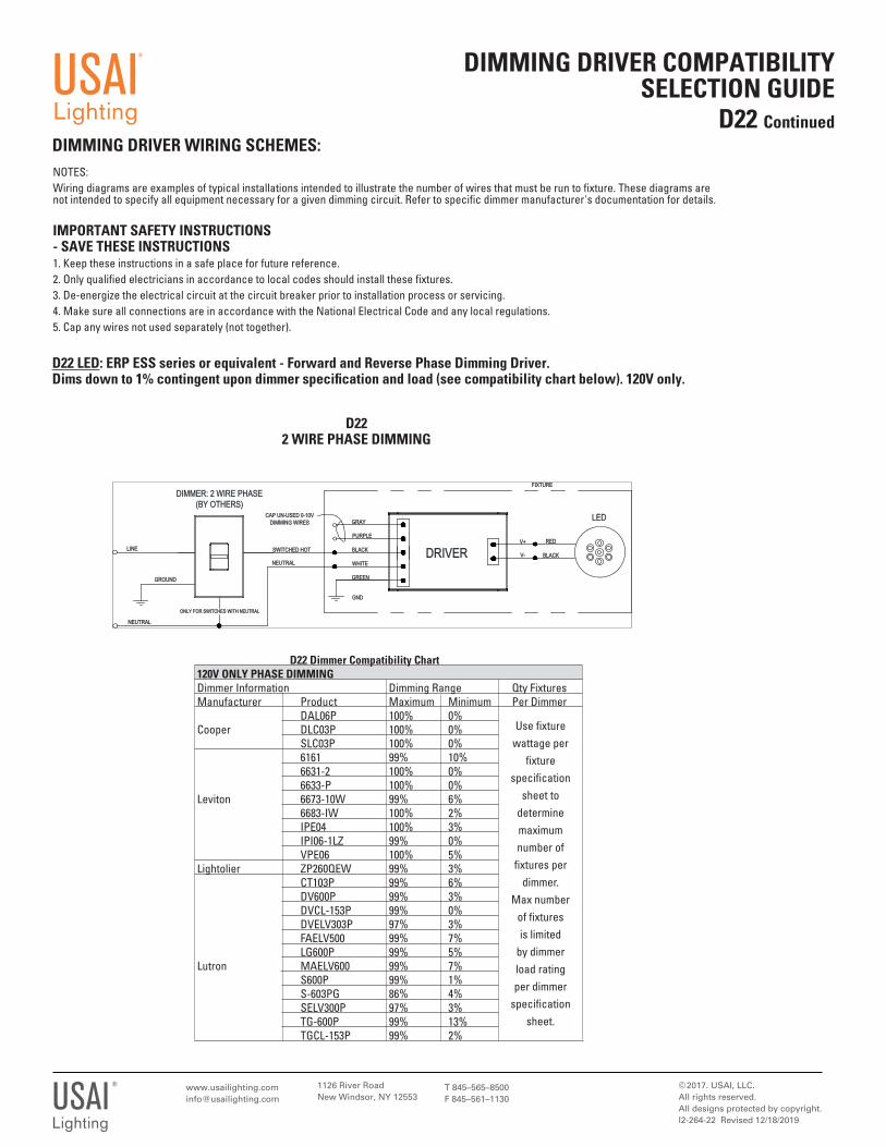
D22 LED: ERP ESS series or equivalent - Forward and Reverse Phase Dimming Driver. Dims down to 1% contingent upon dimmer specifi cation and load (see compatibility chart below). 120V only.
D222 WIRE PHASE DIMMING
Use fixture wattage per
fixture specification
sheet to determine maximum number of
fixtures per dimmer.
Max number of fixtures is limited
by dimmer load rating per dimmer
specification sheet.
D22 Dimmer Compatibility Chart 120V ONLY PHASE DIMMING Dimmer Information Dimming Range Qty Fixtures Manufacturer Product Maximum Minimum Per Dimmer DAL06P 100% 0% Cooper DLC03P 100% 0% SLC03P 100% 0% 6161 99% 10% 6631-2 100% 0% 6633-P 100% 0% Leviton 6673-10W 99% 6% 6683-IW 100% 2% IPE04 100% 3% IPI06-1LZ 99% 0% VPE06 100% 5% Lightolier ZP260QEW 99% 3% CT103P 99% 6% DV600P 99% 3% DVCL-153P 99% 0% DVELV303P 97% 3% FAELV500 99% 7% LG600P 99% 5% Lutron MAELV600 99% 7% S600P 99% 1% S-603PG 86% 4% SELV300P 97% 3% TG-600P 99% 13% TGCL-153P 99% 2%
GND
CAP UN-USED 0-10VDIMMING WIRES
PURPLE
LED
V+
GREEN
BLACKV-
RED
FIXTURE
ONLY FOR SWITCHES WITH NEUTRAL
WHITE
GRAY
BLACK
GROUND
LINE
NEUTRAL
SWITCHED HOT DRIVER
DIMMER: 2 WIRE PHASE(BY OTHERS)
NEUTRAL
1126 River RoadNew Windsor, NY 12553
© 2020. USAI, LLC.All rights reserved. All designs protected by copyright.I2-264-28
T 845–565–8500F 845–561–1130USAI
®
Lighting
DIMMING DRIVER COMPATIBILITY SELECTION GUIDE
D28DIMMING DRIVER WIRING SCHEMES:
USAI®
Lighting
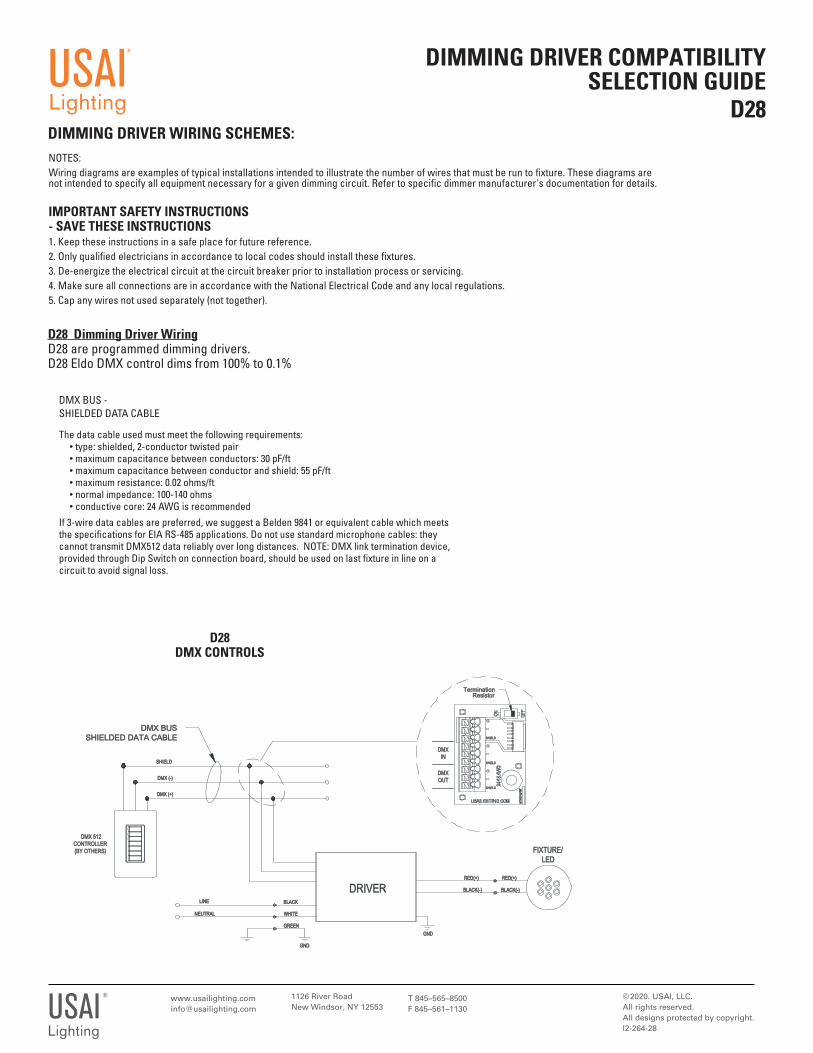
The data cable used must meet the following requirements: • type: shielded, 2-conductor twisted pair • maximum capacitance between conductors: 30 pF/ft • maximum capacitance between conductor and shield: 55 pF/ft • maximum resistance: 0.02 ohms/ft • normal impedance: 100-140 ohms • conductive core: 24 AWG is recommendedIf 3-wire data cables are preferred, we suggest a Belden 9841 or equivalent cable which meets the specifications for EIA RS-485 applications. Do not use standard microphone cables: they cannot transmit DMX512 data reliably over long distances. NOTE: DMX link termination device, provided through Dip Switch on connection board, should be used on last fixture in line on a circuit to avoid signal loss.
DMX BUS - SHIELDED DATA CABLE
NOTES: Wiring diagrams are examples of typical installations intended to illustrate the number of wires that must be run to fixture. These diagrams are not intended to specify all equipment necessary for a given dimming circuit. Refer to specific dimmer manufacturer's documentation for details.
IMPORTANT SAFETY INSTRUCTIONS - SAVE THESE INSTRUCTIONS1. Keep these instructions in a safe place for future reference. 2. Only qualified electricians in accordance to local codes should install these fixtures.3. De-energize the electrical circuit at the circuit breaker prior to installation process or servicing.4. Make sure all connections are in accordance with the National Electrical Code and any local regulations.5. Cap any wires not used separately (not together).
D28 Dimming Driver WiringD28 are programmed dimming drivers. D28 Eldo DMX control dims from 100% to 0.1%
D28DMX CONTROLS
SHSHIEIELDLD
NEUTRALNEUTRAL
SHSHIEIELDLD
GREEGREEN
SHSHIEIELDLD
LINELINE
GNGND
BLBLACKACK
TerminatioTerminationResistorResistor
WHITWHITE
DMDMXOUOUT
GNGND
DMDMXININ
RED(+)RED(+)
DMX BUDMX BUSSHIELDED DATA CABLSHIELDED DATA CABLE
BLBLACK(-)ACK(-)
RED(RED(+)+)
FIXTURE/FIXTURE/LELED
SHIESHIELDLD
DMX DMX (-(-)
DMX DMX (+(+)
BLBLACK(-)ACK(-)
DMX 512 DMX 512CONTCONTROLLERROLLER(BY OTHE(BY OTHERSRS)
DRIVERDRIVER
1126 River RoadNew Windsor, NY 12553
© 2014. USAI, LLC.All rights reserved. All designs protected by copyright.I2-228-3 Revised 09/26/2018
T 845–565–8500F 845–561–1130USAI®
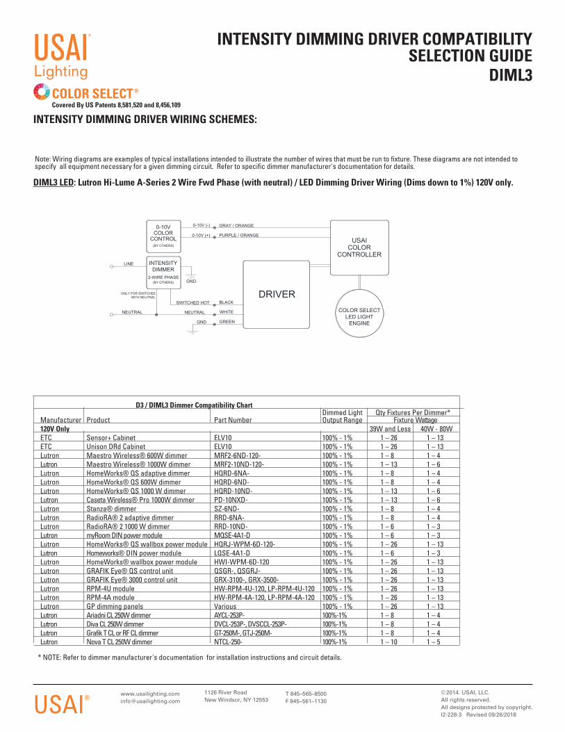
DIML3 LED: Lutron Hi-Lume A-Series 2 Wire Fwd Phase (with neutral) / LED Dimming Driver Wiring (Dims down to 1%) 120V only.
INTENSITY DIMMING DRIVER COMPATIBILITY SELECTION GUIDE
DIML3
Note: Wiring diagrams are examples of typical installations intended to illustrate the number of wires that must be run to fixture. These diagrams are not intended to specify all equipment necessary for a given dimming circuit. Refer to specific dimmer manufacturer's documentation for details.
INTENSITY DIMMING DRIVER WIRING SCHEMES:
COLOR SELECT®
Covered By US Patents 8,581,520 and 8,456,109
USAI®
Lighting
GND
BLACK
GRAY / ORANGE
NEUTRAL
ONLY FOR SWITCHESWITH NEUTRAL
INTENSITYDIMMER
2-WIRE PHASE(BY OTHERS)
PURPLE / ORANGE
NEUTRAL
DRIVERSWITCHED HOT
0-10VCOLOR
CONTROL(BY OTHERS)
0-10V (+)USAI
COLORCONTROLLER
LINE
COLOR SELECTLED LIGHT
ENGINEGREEN
WHITE
GND
0-10V (-)
D3 / DIML3 Dimmer Compatibility Chart Dimmed Light Qty Fixtures Per Dimmer* Manufacturer Product Part Number Output Range Fixture Wattage 120V Only 39W and Less 40W - 80W ETC Sensor+ Cabinet ELV10 100% - 1% 1 – 26 1 – 13 ETC Unison DRd Cabinet ELV10 100% - 1% 1 – 26 1 – 13 Lutron Maestro Wireless® 600W dimmer MRF2-6ND-120- 100% - 1% 1 – 8 1 – 4 Lutron Maestro Wireless® 1000W dimmer MRF2-10ND-120- 100% - 1% 1 – 13 1 – 6 Lutron HomeWorks® QS adaptive dimmer HQRD-6NA- 100% - 1% 1 – 8 1 – 4 Lutron HomeWorks® QS 600W dimmer HQRD-6ND- 100% - 1% 1 – 8 1 – 4 Lutron HomeWorks® QS 1000 W dimmer HQRD-10ND- 100% - 1% 1 – 13 1 – 6 Lutron Caseta Wireless® Pro 1000W dimmer PD-10NXD- 100% - 1% 1 – 13 1 – 6 Lutron Stanza® dimmer SZ-6ND- 100% - 1% 1 – 8 1 – 4 Lutron RadioRA® 2 adaptive dimmer RRD-6NA- 100% - 1% 1 – 8 1 – 4 Lutron RadioRA® 2 1000 W dimmer RRD-10ND- 100% - 1% 1 – 6 1 – 3 Lutron myRoom DIN power module MQSE-4A1-D 100% - 1% 1 – 6 1 – 3 Lutron HomeWorks® QS wallbox power module HQRJ-WPM-6D-120- 100% - 1% 1 – 26 1 – 13 Lutron Homeworks® DIN power module LQSE-4A1-D 100% - 1% 1 – 6 1 – 3 Lutron HomeWorks® wallbox power module HWI-WPM-6D-120 100% - 1% 1 – 26 1 – 13 Lutron GRAFIK Eye® QS control unit QSGR-, QSGRJ- 100% - 1% 1 – 26 1 – 13 Lutron GRAFIK Eye® 3000 control unit GRX-3100-, GRX-3500- 100% - 1% 1 – 26 1 – 13 Lutron RPM-4U module HW-RPM-4U-120, LP-RPM-4U-120 100% - 1% 1 – 26 1 – 13 Lutron RPM-4A module HW-RPM-4A-120, LP-RPM-4A-120 100% - 1% 1 – 26 1 – 13 Lutron GP dimming panels Various 100% - 1% 1 – 26 1 – 13 Lutron Ariadni CL 250W dimmer AYCL-253P- 100%-1% 1 – 8 1 – 4 Lutron Diva CL 250W dimmer DVCL-253P-, DVSCCL-253P- 100%-1% 1 – 8 1 – 4 Lutron Grafik T CL or RF CL dimmer GT-250M-, GTJ-250M- 100%-1% 1 – 8 1 – 4 Lutron Nova T CL 250W dimmer NTCL-250- 100%-1% 1 – 10 1 – 5
* NOTE: Refer to dimmer manufacturer's documentation for installation instructions and circuit details.
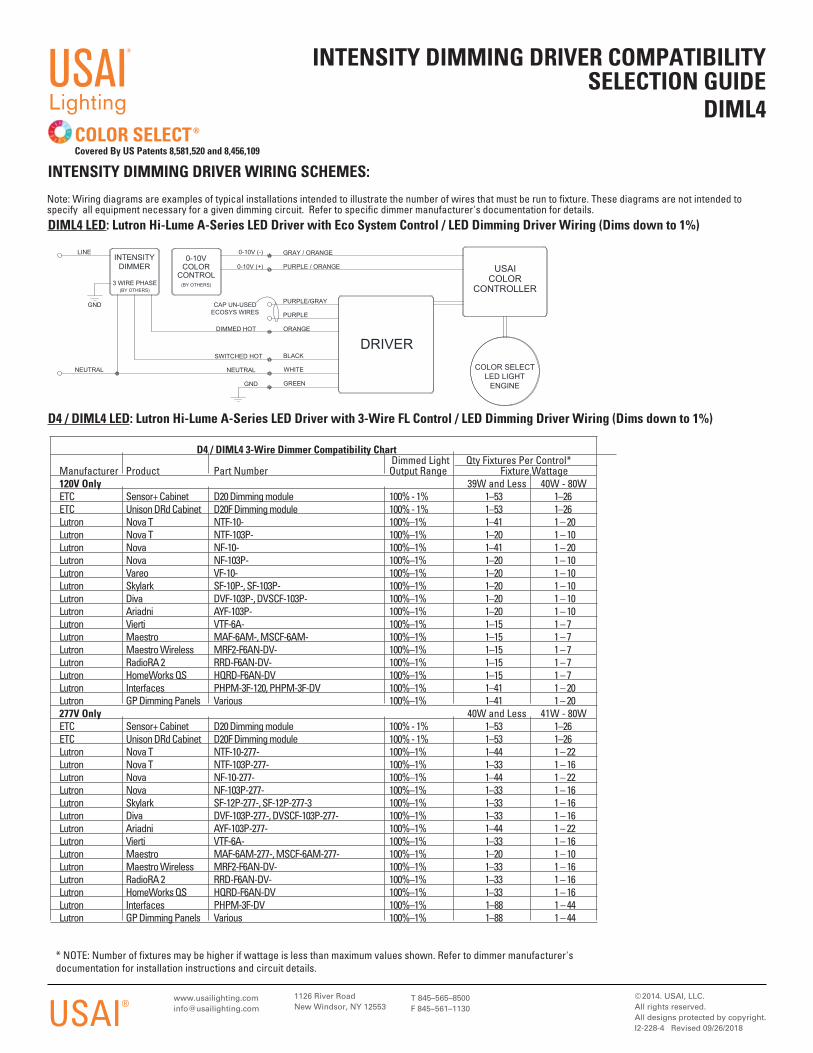
DIML4 LED: Lutron Hi-Lume A-Series LED Driver with Eco System Control / LED Dimming Driver Wiring (Dims down to 1%)
1126 River RoadNew Windsor, NY 12553
© 2014. USAI, LLC.All rights reserved. All designs protected by copyright.I2-228-4 Revised 09/26/2018
T 845–565–8500F 845–561–1130USAI®
INTENSITY DIMMING DRIVER COMPATIBILITY SELECTION GUIDE
DIML4
Note: Wiring diagrams are examples of typical installations intended to illustrate the number of wires that must be run to fixture. These diagrams are not intended to specify all equipment necessary for a given dimming circuit. Refer to specific dimmer manufacturer's documentation for details.
INTENSITY DIMMING DRIVER WIRING SCHEMES:
COLOR SELECT®
Covered By US Patents 8,581,520 and 8,456,109
USAI®
Lighting
SWITCHED HOT
0-10VCOLOR
CONTROL(BY OTHERS)
DRIVER
PURPLE/GRAY
0-10V (+)
COLOR SELECTLED LIGHT
ENGINE
CAP UN-USEDECOSYS WIRES
GREEN
0-10V (-)
GND
WHITE
PURPLE
LINE
DIMMED HOT
USAICOLOR
CONTROLLER
GND
BLACK
ORANGE
NEUTRAL
PURPLE / ORANGE
GRAY / ORANGE
NEUTRAL
INTENSITYDIMMER
3 WIRE PHASE(BY OTHERS)
D4 / DIML4 LED: Lutron Hi-Lume A-Series LED Driver with 3-Wire FL Control / LED Dimming Driver Wiring (Dims down to 1%)
D4 / DIML4 3-Wire Dimmer Compatibility Chart Dimmed Light Qty Fixtures Per Control* Manufacturer Product Part Number Output Range Fixture Wattage 120V Only 39W and Less 40W - 80W ETC Sensor+ Cabinet D20 Dimming module 100% - 1% 1–53 1–26 ETC Unison DRd Cabinet D20F Dimming module 100% - 1% 1–53 1–26 Lutron Nova T NTF-10- 100%–1% 1–41 1 – 20 Lutron Nova T NTF-103P- 100%–1% 1–20 1 – 10 Lutron Nova NF-10- 100%–1% 1–41 1 – 20 Lutron Nova NF-103P- 100%–1% 1–20 1 – 10 Lutron Vareo VF-10- 100%–1% 1–20 1 – 10 Lutron Skylark SF-10P-, SF-103P- 100%–1% 1–20 1 – 10 Lutron Diva DVF-103P-, DVSCF-103P- 100%–1% 1–20 1 – 10 Lutron Ariadni AYF-103P- 100%–1% 1–20 1 – 10 Lutron Vierti VTF-6A- 100%–1% 1–15 1 – 7 Lutron Maestro MAF-6AM-, MSCF-6AM- 100%–1% 1–15 1 – 7 Lutron Maestro Wireless MRF2-F6AN-DV- 100%–1% 1–15 1 – 7 Lutron RadioRA 2 RRD-F6AN-DV- 100%–1% 1–15 1 – 7 Lutron HomeWorks QS HQRD-F6AN-DV 100%–1% 1–15 1 – 7 Lutron Interfaces PHPM-3F-120, PHPM-3F-DV 100%–1% 1–41 1 – 20 Lutron GP Dimming Panels Various 100%–1% 1–41 1 – 20 277V Only 40W and Less 41W - 80W ETC Sensor+ Cabinet D20 Dimming module 100% - 1% 1–53 1–26 ETC Unison DRd Cabinet D20F Dimming module 100% - 1% 1–53 1–26 Lutron Nova T NTF-10-277- 100%–1% 1–44 1 – 22 Lutron Nova T NTF-103P-277- 100%–1% 1–33 1 – 16 Lutron Nova NF-10-277- 100%–1% 1–44 1 – 22 Lutron Nova NF-103P-277- 100%–1% 1–33 1 – 16 Lutron Skylark SF-12P-277-, SF-12P-277-3 100%–1% 1–33 1 – 16 Lutron Diva DVF-103P-277-, DVSCF-103P-277- 100%–1% 1–33 1 – 16 Lutron Ariadni AYF-103P-277- 100%–1% 1–44 1 – 22 Lutron Vierti VTF-6A- 100%–1% 1–33 1 – 16 Lutron Maestro MAF-6AM-277-, MSCF-6AM-277- 100%–1% 1–20 1 – 10 Lutron Maestro Wireless MRF2-F6AN-DV- 100%–1% 1–33 1 – 16 Lutron RadioRA 2 RRD-F6AN-DV- 100%–1% 1–33 1 – 16 Lutron HomeWorks QS HQRD-F6AN-DV 100%–1% 1–33 1 – 16 Lutron Interfaces PHPM-3F-DV 100%–1% 1–88 1 – 44 Lutron GP Dimming Panels Various 100%–1% 1–88 1 – 44
* NOTE: Number of fixtures may be higher if wattage is less than maximum values shown. Refer to dimmer manufacturer's documentation for installation instructions and circuit details.
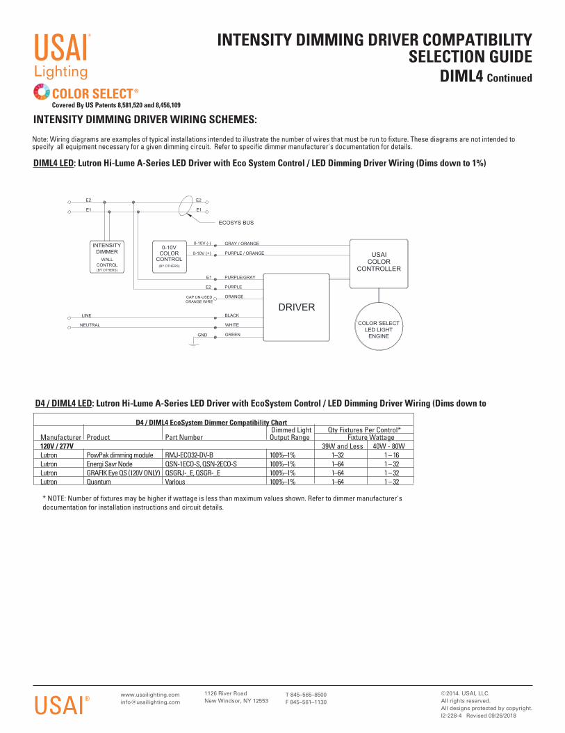
DIML4 LED: Lutron Hi-Lume A-Series LED Driver with Eco System Control / LED Dimming Driver Wiring (Dims down to 1%)
1126 River RoadNew Windsor, NY 12553
© 2014. USAI, LLC.All rights reserved. All designs protected by copyright.I2-228-4 Revised 09/26/2018
T 845–565–8500F 845–561–1130USAI®
INTENSITY DIMMING DRIVER COMPATIBILITY SELECTION GUIDE
DIML4 Continued
Note: Wiring diagrams are examples of typical installations intended to illustrate the number of wires that must be run to fixture. These diagrams are not intended to specify all equipment necessary for a given dimming circuit. Refer to specific dimmer manufacturer's documentation for details.
INTENSITY DIMMING DRIVER WIRING SCHEMES:
COLOR SELECT®
Covered By US Patents 8,581,520 and 8,456,109
USAI®
Lighting
E1
E2
GREEN
PURPLE / ORANGE
LINE
COLOR SELECTLED LIGHT
ENGINE
E1 PURPLE/GRAY
0-10V (+)
E1
GND
0-10VCOLOR
CONTROL(BY OTHERS)
WHITE
E2 PURPLE
0-10V (-)
ECOSYS BUS
ORANGECAP UN-USEDORANGE WIRE
USAICOLOR
CONTROLLER
INTENSITYDIMMER
WALLCONTROL(BY OTHERS)
BLACK
GRAY / ORANGE
NEUTRAL
DRIVER
E2
D4 / DIML4 EcoSystem Dimmer Compatibility Chart Dimmed Light Qty Fixtures Per Control* Manufacturer Product Part Number Output Range Fixture Wattage 120V / 277V 39W and Less 40W - 80W Lutron PowPak dimming module RMJ-ECO32-DV-B 100%–1% 1–32 1 – 16 Lutron Energi Savr Node QSN-1ECO-S, QSN-2ECO-S 100%–1% 1–64 1 – 32 Lutron GRAFIK Eye QS (120V ONLY) QSGRJ-_E, QSGR-_E 100%–1% 1–64 1 – 32 Lutron Quantum Various 100%–1% 1–64 1 – 32
D4 / DIML4 LED: Lutron Hi-Lume A-Series LED Driver with EcoSystem Control / LED Dimming Driver Wiring (Dims down to
* NOTE: Number of fixtures may be higher if wattage is less than maximum values shown. Refer to dimmer manufacturer's documentation for installation instructions and circuit details.
1126 River RoadNew Windsor, NY 12553
INTENSITY DIMMING DRIVER COMPATIBILITY SELECTION GUIDE
DIML6A & 6BDIML6E & DIML6F
Note: Wiring diagrams are examples of typical installations intended to illustrate the number of wires that must be run to fixture. These diagrams are not intended to specify all equipment necessary for a given dimming circuit. Refer to specific dimmer manufacturer's documentation for details.
INTENSITY DIMMING DRIVER WIRING SCHEMES:
COLOR SELECT®
Covered By US Patents 8,581,520 and 8,456,109
USAI®
Lighting
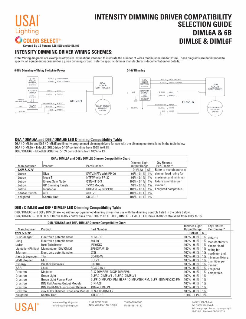
D6A / DIML6A and D6E / DIML6E LED Dimming Compatibility TableD6A / DIML6A and D6E / DIML6E are linearly programmed dimming drivers for use with the dimming controls listed in the table belowD6A / DIML6A = EldoLED SOLOdrive 0-10V control dims from 100% to 0.1%D6E / DIML6E = EldoLED ECOdrive 0-10V control dims from 100% to 1%
Dimmed Light Qty Fixtures Manufacturer Product Part Number Output Range Per Dimmer* 120V & 277V DIML6A 6E Lutron Diva DVTV/NFTV with PP-20 99% - 0.1% 1% Lutron Nova T NTFTV with PP-20 99% - 0.1% 1% Lutron Energi Savr Node QSN-4T16-S 100% - 0.1% 1% Lutron GP Dimming Panels TVM2 Module 99% - 0.1% 1% Lutron Interfaces GRX-TVI w/ GRX3503 100% - 0.1% 1% Sensor Switch nIO nIO EZ 100% - 0.1% 1% enlighted Control Unit CU-3E-1R 100% - 0.1% 1%
Refer to manufacturer's dimmer load rating for maximum and minimum fixture quantities per dimmer.Enlighted compatible.
D6A / DIML6A and D6E / DIML6E Dimmer Compatibility Chart
D6B / DIML6B and D6F / DIML6F LED Dimming Compatibility TableD6B / DIML6B and D6F / DIML6F are logarithmic-programmed dimming drivers for use with the dimming controls listed in the table belowD6B / DIML6B = EldoLED SOLOdrive 0-10V control dims from 100% to 0.1% D6F / DIML6F = EldoLED ECOdrive 0-10V control dims from 100% to 1%
D6B / DIML6B and D6F / DIML6F Dimmer Compatibility Chart Dimmed Light Qty Fixtures Manufacturer Product Part Number Output Range Per Dimmer* 120V & 277V DIML6B 6F Bush-Jaeger Electronic potentiometer 2112U-101 100% - 0.1% 1% Jung Electronic potentiometer 240-10 100% - 0.1% 1% Leviton Iluma Tech dimmer IP710-DLX 100% - 0.1% 1% Lightolier (Philips) Momentum (120V ONLY) ZP600FAM120 100% - 0.1% 1% Merten Electronic potentiometer 5729 100% - 0.1% 1% Pass & Seymour Titan CD4FB-W 100% - 0.1% 1% Watt Stopper Miro DCLV1 100% - 0.1% 1% Synergy Wallbox Dimmers ISD BC 100% - 0.1% 1% ABB i-bus SD/S 2.16.1 100% - 0.1% 1% Crestron Modules GLX-DIMFLV8, GLXP-DIMFLV8 100% - 0.1% 1% Crestron Green Light GLPAC-DIMFLV4-, GLPAC-DIMFLV8- 100% - 0.1% 1% Crestron Green Light Power Pack GLPP-DIMFLVEX-PM, GLPP-1DIMFLV2EX-PM, GLPP-1DIMFLV3EX-PM 100% - 0.1% 1% Crestron DIN Rail Analog Output Module DIN-A08 100% - 0.1% 1% Crestron DIN Rail 0-10V Fluorescent Dimmer DIN-4DIMFLV4 100% - 0.1% 1% Crestron iLux 0-10V Dimmer Expansion Module CLS-EXP-DIMFLV 100% - 0.1% 1% enlighted Control Unit CU-3E-1R 100% - 0.1% 1%
Refer to manufacturer's dimmer load rating for maximum and minimum fixture quantities per dimmer.Enlighted compatible.
© 2014. USAI, LLC.All rights reserved. All designs protected by copyright.I2-228-6 Revised 08/28/2019
T 845–565–8500F 845–561–1130
GRAY / ORANGE
NEUTRAL
0-10V (+)
WHITE COLOR SELECTLED LIGHT
ENGINE
BLACK
USAICOLOR
CONTROLLER
PURPLE / ORANGE
INTENSITYDIMMER
0-10V(BY OTHERS)
SWITCHED HOTDRIVER
0-10V (-)
GND
GRAY
NEUTRAL
0-10V (+)
0-10VCOLOR
CONTROL(BY OTHERS)
PURPLE
GREEN
LINE
0-10V (-)
(BY OTHERS)
CLASS 2CONTROL WIRES
RELAYCOLOR SELECT
LED LIGHTENGINEGREEN
WHITE
PURPLE / ORANGE
PURPLE
USAICOLOR
CONTROLLER
0-10V (+)
BLACK
0-10V (+)
GND
INTENSITYDIMMER
0-10Vw/POWER
SWITCHING(BY OTHERS)
GND
NEUTRAL NEUTRAL
0-10V (-)
0-10V (-)
LINE
SWITCHED HOT
GRAY / ORANGE
DRIVER
GRAY
0-10VCOLOR
CONTROL(BY OTHERS)
0-10V Dimming w/ Relay Switch to Power 0-10V Dimming
1126 River RoadNew Windsor, NY 12553
© 2014. USAI, LLC.All rights reserved. All designs protected by copyright.I2-228-7 Revised 09/26/2018
T 845–565–8500F 845–561–1130USAI®
INTENSITY DIMMING DRIVER COMPATIBILITY SELECTION GUIDE
DIML7
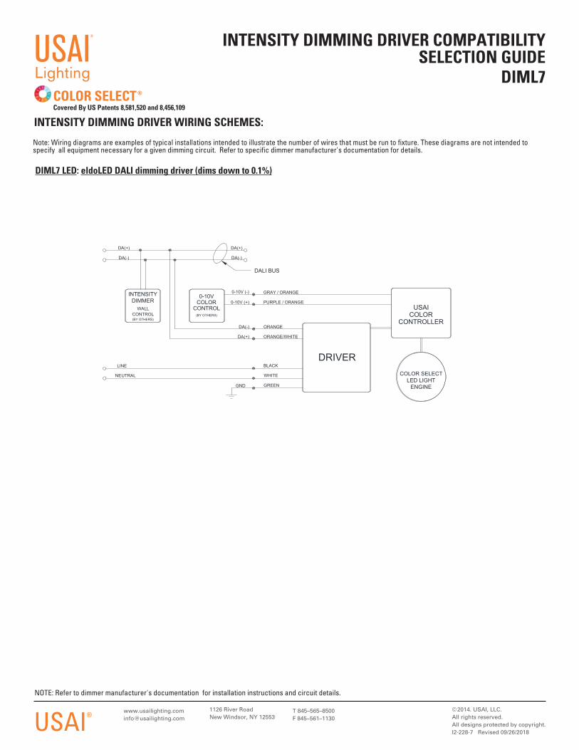
DIML7 LED: eldoLED DALI dimming driver (dims down to 0.1%)
NOTE: Refer to dimmer manufacturer's documentation for installation instructions and circuit details.
Note: Wiring diagrams are examples of typical installations intended to illustrate the number of wires that must be run to fixture. These diagrams are not intended to specify all equipment necessary for a given dimming circuit. Refer to specific dimmer manufacturer's documentation for details.
INTENSITY DIMMING DRIVER WIRING SCHEMES:
COLOR SELECT®
Covered By US Patents 8,581,520 and 8,456,109
USAI®
Lighting
GREEN
PURPLE / ORANGE
BLACK
DA(+)
NEUTRAL
ORANGE
DRIVER
0-10V (+)
DALI BUS
DA(-)
LINE
ORANGE/WHITE
0-10V (-)
DA(-)
0-10VCOLOR
CONTROL(BY OTHERS)
DA(+)
COLOR SELECTLED LIGHT
ENGINE
USAICOLOR
CONTROLLER
INTENSITYDIMMER
WALLCONTROL(BY OTHERS)
GRAY / ORANGE
GND
DA(-)
WHITE
DA(+)
1126 River RoadNew Windsor, NY 12553
© 2020. USAI, LLC.All rights reserved. All designs protected by copyright.I2-228-28
T 845–565–8500F 845–561–1130USAI®
INTENSITY DIMMING DRIVER COMPATIBILITY SELECTION GUIDE
D28
INTENSITY DIMMING DRIVER WIRING SCHEMES:
COLOR SELECT®
Covered By US Patents 8,581,520 and 8,456,109
USAI®
Lighting
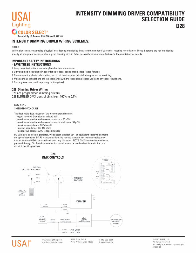
The data cable used must meet the following requirements: • type: shielded, 2-conductor twisted pair • maximum capacitance between conductors: 30 pF/ft • maximum capacitance between conductor and shield: 55 pF/ft • maximum resistance: 0.02 ohms/ft • normal impedance: 100-140 ohms • conductive core: 24 AWG is recommendedIf 3-wire data cables are preferred, we suggest a Belden 9841 or equivalent cable which meets the specifications for EIA RS-485 applications. Do not use standard microphone cables: they cannot transmit DMX512 data reliably over long distances. NOTE: DMX link termination device, provided through Dip Switch on connection board, should be used on last fixture in line on a circuit to avoid signal loss.
DMX BUS - SHIELDED DATA CABLE
NOTES: Wiring diagrams are examples of typical installations intended to illustrate the number of wires that must be run to fixture. These diagrams are not intended to specify all equipment necessary for a given dimming circuit. Refer to specific dimmer manufacturer's documentation for details.
IMPORTANT SAFETY INSTRUCTIONS - SAVE THESE INSTRUCTIONS1. Keep these instructions in a safe place for future reference. 2. Only qualified electricians in accordance to local codes should install these fixtures.3. De-energize the electrical circuit at the circuit breaker prior to installation process or servicing.4. Make sure all connections are in accordance with the National Electrical Code and any local regulations.5. Cap any wires not used separately (not together).
D28 Dimming Driver WiringD28 are programmed dimming drivers. D28 ELDOLED DMX control dims from 100% to 0.1%
D28DMX CONTROLS
0-10V (+)
LINE
TerminationResistor
TO NEXTFIXTURE
GND
DMX (-)
WHITE
SHIELD
PURPLE / ORANGE
DMX BUSSHIELDED DATA CABLE
DMXIN
0-10V (-)
USAICOLOR
CONTROLLER
SHIELD
DMX (+)
BLACK
0-10V (+)
0-10V (-)
GND
DRIVER
COLOR SELECTLED LIGHT
ENGINE
NEUTRAL
SHIELD
0-10VCOLOR
CONTROL(BY OTHERS)
GREEN
DMXOUT
DMX 512CONTROLLER
(BYOTHERS)
TO NEXTFIXTURE
SHIELD
GRAY / ORANGE
Recommended