
Blue Pearl Software
------------------------------------------------------------------------------------------------------------------------------------------
P a g e | 1 Copyright 2017 Blue Pearl Software
BLUE PEARL SOFTWARE
Blue Pearl Verification Methodology Guide
2/13/2018
Blue Pearl Software
------------------------------------------------------------------------------------------------------------------------------------------
P a g e | 2 Copyright 2017 Blue Pearl Software
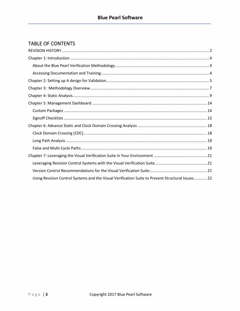
REVISION HISTORY Date Version Revision
09/15/2017 2017.2 Initial Release version 1.0
02/14/2018 2018.1 1.1
Blue Pearl Software
------------------------------------------------------------------------------------------------------------------------------------------
P a g e | 3 Copyright 2017 Blue Pearl Software
TABLE OF CONTENTS REVISION HISTORY ........................................................................................................................................ 2
Chapter 1: Introduction ................................................................................................................................ 4
About the Blue Pearl Verification Methodology ....................................................................................... 4
Accessing Documentation and Training .................................................................................................... 4
Chapter 2: Setting up A design for Validation ............................................................................................... 5
Chapter 3: Methodology Overview .............................................................................................................. 7
Chapter 4: Static Analysis .............................................................................................................................. 9
Chapter 5: Management Dashboard .......................................................................................................... 14
Custom Packages .................................................................................................................................... 14
Signoff Checklists .................................................................................................................................... 15
Chapter 6: Advance Static and Clock Domain Crossing Analysis ................................................................ 18
Clock Domain Crossing (CDC) .................................................................................................................. 18
Long Path Analysis .................................................................................................................................. 19
False and Multi-Cycle Paths .................................................................................................................... 19
Chapter 7: Leveraging the Visual Verification Suite in Your Environment ................................................. 21
Leveraging Revision Control Systems with the Visual Verification Suite ................................................ 21
Version Control Recommendations for the Visual Verification Suite: .................................................... 21
Using Revision Control Systems and the Visual Verification Suite to Prevent Structural Issues ............ 22
Blue Pearl Software
------------------------------------------------------------------------------------------------------------------------------------------
P a g e | 4 Copyright 2017 Blue Pearl Software
CHAPTER 1: INTRODUCTION
About the Blue Pearl Verification Methodology The Blue Pearl Software Verification Methodology is a set of best practices and recommendations
intended to streamline verification and signoff of IP, FPGA and ASIC RTL. The methodology is intended to
be used in conjunction with the Visual Verification Suite in order to reduce design risk and to accelerate
development.
The Visual Verification Suite performs static and formal analysis of RTL based on a series of rules and
guidelines that reflect good coding practice, finding common errors that can cause issues such as
hardware vs. simulation mismatches and metastability caused by Clock Domain Crossings and Reset
circuity. When these rules are breached, the tool flags the potential bugs within that code for review or
waiver by the design engineer. The goal of this methodology is to reduce “noise” or “false positive” results
by providing a step-by-step sequence that allows the engineer to most efficiently decide which of the
potential bugs can be waived and which need to be fixed.
This document is intended to be used by Design Engineers who are developing new RTL for new designs
and building on legacy designs, and by Verification Engineers who must verify the entire design.
This guide includes high-level information, guidelines and recommendations for the following topics:
• Chapter 2: Setting up your design for validation: This chapter covers options such as top down
vs. bottom up verification, leveraging legacy design, 3rd party IP and imported projects from Intel,
Microsemi and Xilinx.
• Chapter 3: Methodology overview: This chapter includes high level suggestions to reduce noisy
analysis so that you can focus on the most important warnings and errors.
• Chapter 4: Static Analysis: This chapter will walk you through best practices for statically analyzing
designs to eliminate structural issues prior to simulation and synthesis.
• Chapter 5: Management Dashboard: This chapter will discuss how to set up RTL signoff and track
progress over time.
• Chapter 6: Advanced Static Analysis and Clock Domain Crossing Analysis: This chapter will
discuss setting up your design for CDC analysis and best practices to avoid metastability.
• Chapter 7: Leveraging the Visual Verification Suite in your environment: This chapter covers
running in revision control environments and moving between Tcl command line mode and the
Graphical User Interface.
Accessing Documentation and Training This document is not intended to serve as basic tool training. Blue Pearl’s Visual Verification Suite provides
built in documents, tutorials and links to videos that can be found under the help menu in the graphical
user interface. In addition, for new qualifying purchases JumpStart Training, a “build your own learning”
program, is included with the purchase. The JumpStart is tailor designed to give every user the
foundational knowledge to be successful using the Visual Verification Suite to improve code quality,
accelerate verification and decrease design risk. The JumpStart accelerates ramp-up and adoption to
ensure Hardware, IP and Verification engineers are productive from day one.
Blue Pearl Software
------------------------------------------------------------------------------------------------------------------------------------------
P a g e | 5 Copyright 2017 Blue Pearl Software
CHAPTER 2: SETTING UP A DESIGN FOR VALIDATION Setting up a design is important so analysis is not impacted by “noise” and finding errors is not time
consuming. The correct approach is to start to analyze bottom-up, breaking up the bigger problem into
smaller ones, just as one would perform synthesis of a design. A bottom-up approach limits the number
of messages to be analyzed and makes it easier to find and fix issues. A bottom-up approach to analysis
also limits the generation of false positive warnings in scenarios where rules which are meant to be run
on the module level could flag issues across module boundaries and vice versa.
Blue Pearl’s Visual Verification Suite allows the user to do bottom-up analysis without having to make
changes to the design setup. By changing the root module to be analyzed, designers have the ability to
maintain a single setup file without having to make extensive changes to run at different hierarchal levels.
This also allows the same setup file to be used between designers who are targeting different blocks for
analysis of the design.
Using Legacy designs (Design Reuse): Analyzing as you code is the right way to verify your design, but
most designs today reuse code from legacy designs, modifying it as needed. Setting up analysis for a design
that is being reused is crucial to proper project planning. During design specification, it is invaluable to use
static analysis on any previous HDL code slated for reuse. If there are numerous issues identified during
the exploratory analysis, design teams can properly plan for the effort it will take to get that code up to
current standards. This allows design teams to accurately forecast the effort it will take to work with this
code. For legacy designs, once the entire design has been set up, use the bottom-up approach for analysis.
New Design: A new design could be your entire design or new RTL to be used along with the legacy
design. Any new RTL code should be verified as you code. Running static analysis on each new design file
as it is generated will reduce the effort required to run verification on that file. The designer should not
wait until the entire design is complete before beginning static analysis.
Set up your design: Designers can set up their design for verification using a file list from their existing
synthesis or simulation setup. By correctly setting the root module they can achieve the bottom-up flow
for verification.
For FPGA developers, the Visual Verification Suite has the capability to import FPGA projects directly into
the tool. The designers can specify, from newer versions of those tools, the Intel®/Altera Quartus® Prime
Software .qsf file, Microsemi® Libero® Design Software .prjx file, Synopsys® Synplify® Pro .prj file, or the
Xilinx® Vivado® Design Suite .xpf file. This allows the designer to keep the same setup file as the FPGA
tools, and any modification to the FPGA project is automatically reflected in their verification flow.
3rd Party IP: Most designs today have 3rd party IP integrated in them. In many cases the IP is encrypted
and creating a black box is not sufficient for a comprehensive analysis. If the RTL is provided for the IP, it
should be analyzed separately before it is included in the top-level design to ensure that it is up to the
design team's standards, to defend against taking in poorly verified cores. It is well known that not all IP
developers test their IP for all options. Black-boxing the IP after it is accepted into the whole design is
still the way to go, as changing the code for the IP at that point is not possible.
If the goal is to perform Clock Domain Crossing (CDC) analysis for the IP, then a User Grey Cell (UGC) needs
to be created for the IP instead of a black box. The UGC can be created for both encrypted as well as for
Blue Pearl Software
------------------------------------------------------------------------------------------------------------------------------------------
P a g e | 6 Copyright 2017 Blue Pearl Software
non-encrypted RTL. The UGC preserves the information of the IP at the boundary, allowing the designer
to effectively do CDC for the IP and the rest of the design. For more information on creating a UGC please
see our app note, Reduce Metastability by Using a User Grey Cell Methodology for IP and FPGA Clock
Domain Crossing Analysis.
Blue Pearl Software
------------------------------------------------------------------------------------------------------------------------------------------
P a g e | 7 Copyright 2017 Blue Pearl Software
CHAPTER 3: METHODOLOGY OVERVIEW
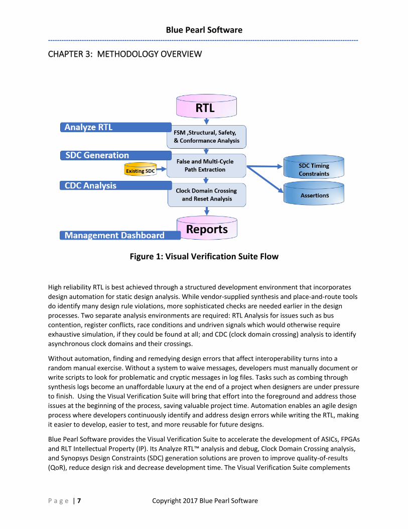
Figure 1: Visual Verification Suite Flow
High reliability RTL is best achieved through a structured development environment that incorporates
design automation for static design analysis. While vendor-supplied synthesis and place-and-route tools
do identify many design rule violations, more sophisticated checks are needed earlier in the design
processes. Two separate analysis environments are required: RTL Analysis for issues such as bus
contention, register conflicts, race conditions and undriven signals which would otherwise require
exhaustive simulation, if they could be found at all; and CDC (clock domain crossing) analysis to identify
asynchronous clock domains and their crossings.
Without automation, finding and remedying design errors that affect interoperability turns into a
random manual exercise. Without a system to waive messages, developers must manually document or
write scripts to look for problematic and cryptic messages in log files. Tasks such as combing through
synthesis logs become an unaffordable luxury at the end of a project when designers are under pressure
to finish. Using the Visual Verification Suite will bring that effort into the foreground and address those
issues at the beginning of the process, saving valuable project time. Automation enables an agile design
process where developers continuously identify and address design errors while writing the RTL, making
it easier to develop, easier to test, and more reusable for future designs.
Blue Pearl Software provides the Visual Verification Suite to accelerate the development of ASICs, FPGAs
and RLT Intellectual Property (IP). Its Analyze RTL™ analysis and debug, Clock Domain Crossing analysis,
and Synopsys Design Constraints (SDC) generation solutions are proven to improve quality-of-results
(QoR), reduce design risk and decrease development time. The Visual Verification Suite complements
Blue Pearl Software
------------------------------------------------------------------------------------------------------------------------------------------
P a g e | 8 Copyright 2017 Blue Pearl Software
RTL simulation solutions provided by EDA and FPGA vendors by ensuring code and SDC quality along
with clocking integrity. Engineered to maximize RTL find/fix rates with build in features that help in
examining analysis defects via automatically pruned schematics of the error, the Visual Verification Suite
uniquely provides easy setup, consistent results, Management Dashboard for complete push-button
analytics, and runs on both Linux and Windows.
Blue Pearl Software
------------------------------------------------------------------------------------------------------------------------------------------
P a g e | 9 Copyright 2017 Blue Pearl Software
CHAPTER 4: STATIC ANALYSIS The addressing of issues found during static analysis is best done in a sequence in which the first issues
addressed are either those whose solution will also solve other apparent issues, or whose solution may
cause or reveal other types of issues which can then be addressed separately. With that in mind, Blue
Pearl recommends the following sequence.
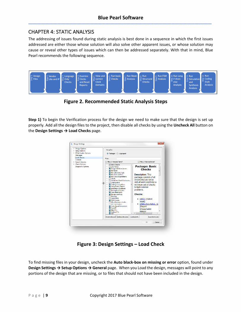
Figure 2. Recommended Static Analysis Steps
Step 1) To begin the Verification process for the design we need to make sure that the design is set up
properly. Add all the design files to the project, then disable all checks by using the Uncheck All button on
the Design Settings → Load Checks page.
Figure 3: Design Settings – Load Check
To find missing files in your design, uncheck the Auto black-box on missing or error option, found under
Design Settings → Setup Options → General page. When you Load the design, messages will point to any
portions of the design that are missing, or to files that should not have been included in the design.
Blue Pearl Software
------------------------------------------------------------------------------------------------------------------------------------------
P a g e | 10 Copyright 2017 Blue Pearl Software
Step 2) FPGA designs need to enable the corresponding FPGA Vendor library support. This may resolve
some of the missing files if the design refers to FPGA library cells. IPs need to be black-boxed or UGC
models need to be created depending on the verification goal as discussed in chapter 2.3. Once the
missing files have been resolved, if there are any more missing files that enable the Auto black-box on
missing or error option. This will allow the design to be loaded without the missing files.
Step 3) The Visual Verification Suite may produce messages with several different prefixes, including ELAB,
VERI, VHDL, and BPS. Of these, all except BPS are language-only messages produced during parsing and
are not under the control of any specific check. Address the issues indicated by the warnings or errors
with any prefix other than BPS.
The tools found under View Results → Compare Result Summaries and View Results → Compare Results
will help you highlight run-to-run results differences as you fix your code.
Step 4) Once parsing- and language-related issues are addressed, the next step is to examine the Clock
and Reset Reports and make sure the Visual Verification Suite has properly identified all clocks and resets.
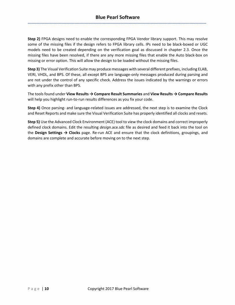
Step 5) Use the Advanced Clock Environment (ACE) tool to view the clock domains and correct improperly
defined clock domains. Edit the resulting design.ace.sdc file as desired and feed it back into the tool on
the Design Settings → Clocks page. Re-run ACE and ensure that the clock definitions, groupings, and
domains are complete and accurate before moving on to the next step.
Blue Pearl Software
------------------------------------------------------------------------------------------------------------------------------------------
P a g e | 11 Copyright 2017 Blue Pearl Software
Figure 4: Advanced Clock Environment
Step 6) After your clocks, clock domains, and resets are properly identified, enable your desired checks.
At this point, it is worth reiterating and emphasizing that you should NEVER ENABLE ALL CHECKS! Many
checks are mutually exclusive or contradictory. However, too narrow a focus may be just as bad as too
broad a focus. This is where utilizing Blue Pearl's customer support can help your design team get started.
We have extensive experience with what options and which checks are best suited to meet your goals.
Enabling only a small set of checks to target a specific issue is especially inefficient for larger designs
because of overhead, and you risk not reporting a seemingly unrelated issue that is masked by too narrow
of a subset of checks. The best way to focus on a given set of issues is to use the Analysis Report's filtering
mechanisms on the results obtained by running all relevant checks simultaneously.
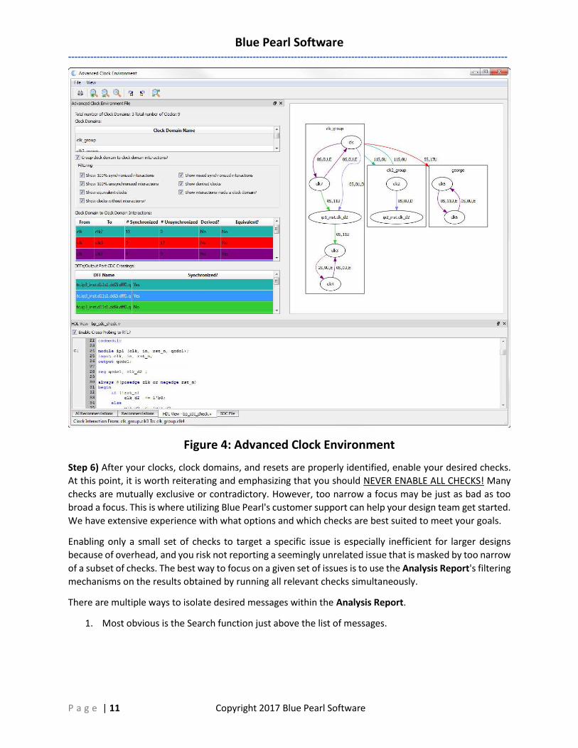
There are multiple ways to isolate desired messages within the Analysis Report.
1. Most obvious is the Search function just above the list of messages.
Blue Pearl Software
------------------------------------------------------------------------------------------------------------------------------------------
P a g e | 12 Copyright 2017 Blue Pearl Software
Figure 5: Analysis Report - Search
2. Packages are helpful not only for enabling a set of checks prior to analysis, they can also be used
after an analysis in the Report Filter to see only those messages that interest you.
If you are unsure of which checks to enable, we recommend the Basic Checks package. As your experience
grows, the next chapter will discuss how to create a custom package of your own.
Fixing the code is not the only way to deal with issues found by the tool. In some carefully-considered
cases, you may wish to waive messages. The Visual Verification Suite provides a Waivers Manager to help
you create and manage waivers, held in one or more waiver files, for messages and clock domain
crossings.
Step 7) Examine reset issues, including asynchronous vs. synchronous resets and, in the case of
asynchronous resets, ensuring that de-assertion is synchronized with the clock to avoid recovery time
violations. Some of the checks found in the Design initializes/resets package may be helpful for this
purpose, but don’t turn on the entire package, since some checks are mutually exclusive.
Step 8) The types of issue that should be addressed next are structural issues, such as unconnected nets
or pins, mismatches in bit width, and issues involving case statements.
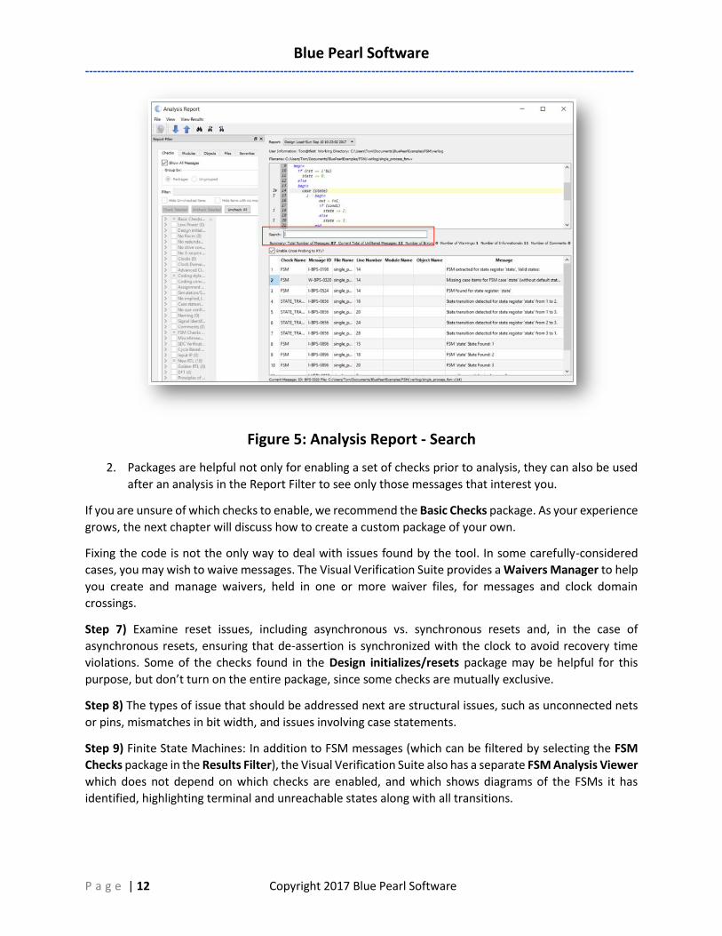
Step 9) Finite State Machines: In addition to FSM messages (which can be filtered by selecting the FSM
Checks package in the Results Filter), the Visual Verification Suite also has a separate FSM Analysis Viewer
which does not depend on which checks are enabled, and which shows diagrams of the FSMs it has
identified, highlighting terminal and unreachable states along with all transitions.
Blue Pearl Software
------------------------------------------------------------------------------------------------------------------------------------------
P a g e | 13 Copyright 2017 Blue Pearl Software
Figure 6: Finite State Machine Viewer
Step 10) Long if-then-else (ITE) chains: In addition to a check called ITE_DEPTH, which has a threshold you
can enable, there is a separate Text Report that will list the lengths of all ITE chains in your design.
Step 11) Examine any simulation vs. synthesis issues. There's a package called Simulation/Synthesis
included in the tool.
Step 12) Coding style: Coding issues are flagged by checks found in packages with names like Coding Style,
Coding Conventions, Naming, and Comments. These checks flag issues which have no effect on the
functionality of the code, but pertain to readability and reusability issues. These issues are of most concern
to larger companies and design groups, where miscommunication can happen more easily, and to IP
vendors, whose final product is the code itself rather than just the functionality created by that code.
Again, do not simply enable an entire package, since some checks within each package may be mutually
contradictory.
Blue Pearl Software
------------------------------------------------------------------------------------------------------------------------------------------
P a g e | 14 Copyright 2017 Blue Pearl Software
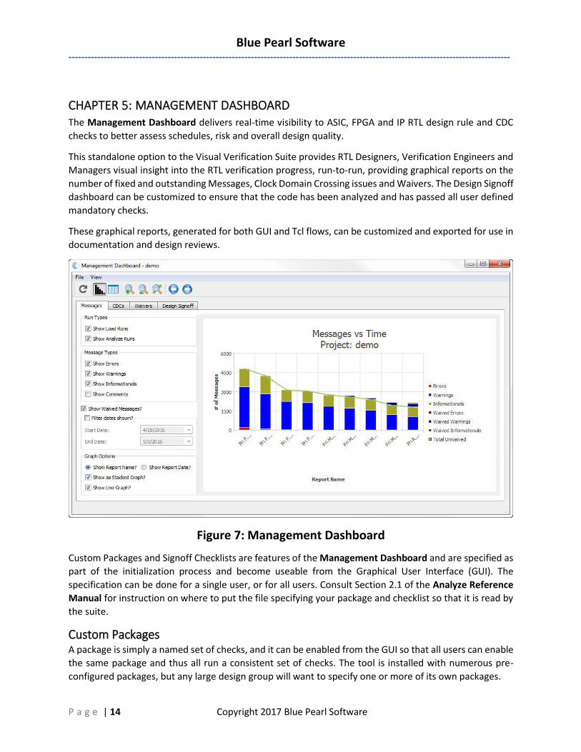
CHAPTER 5: MANAGEMENT DASHBOARD The Management Dashboard delivers real-time visibility to ASIC, FPGA and IP RTL design rule and CDC
checks to better assess schedules, risk and overall design quality.
This standalone option to the Visual Verification Suite provides RTL Designers, Verification Engineers and
Managers visual insight into the RTL verification progress, run-to-run, providing graphical reports on the
number of fixed and outstanding Messages, Clock Domain Crossing issues and Waivers. The Design Signoff
dashboard can be customized to ensure that the code has been analyzed and has passed all user defined
mandatory checks.
These graphical reports, generated for both GUI and Tcl flows, can be customized and exported for use in
documentation and design reviews.
Figure 7: Management Dashboard
Custom Packages and Signoff Checklists are features of the Management Dashboard and are specified as
part of the initialization process and become useable from the Graphical User Interface (GUI). The
specification can be done for a single user, or for all users. Consult Section 2.1 of the Analyze Reference
Manual for instruction on where to put the file specifying your package and checklist so that it is read by
the suite.
Custom Packages A package is simply a named set of checks, and it can be enabled from the GUI so that all users can enable
the same package and thus all run a consistent set of checks. The tool is installed with numerous pre-
configured packages, but any large design group will want to specify one or more of its own packages.
Blue Pearl Software
------------------------------------------------------------------------------------------------------------------------------------------
P a g e | 15 Copyright 2017 Blue Pearl Software
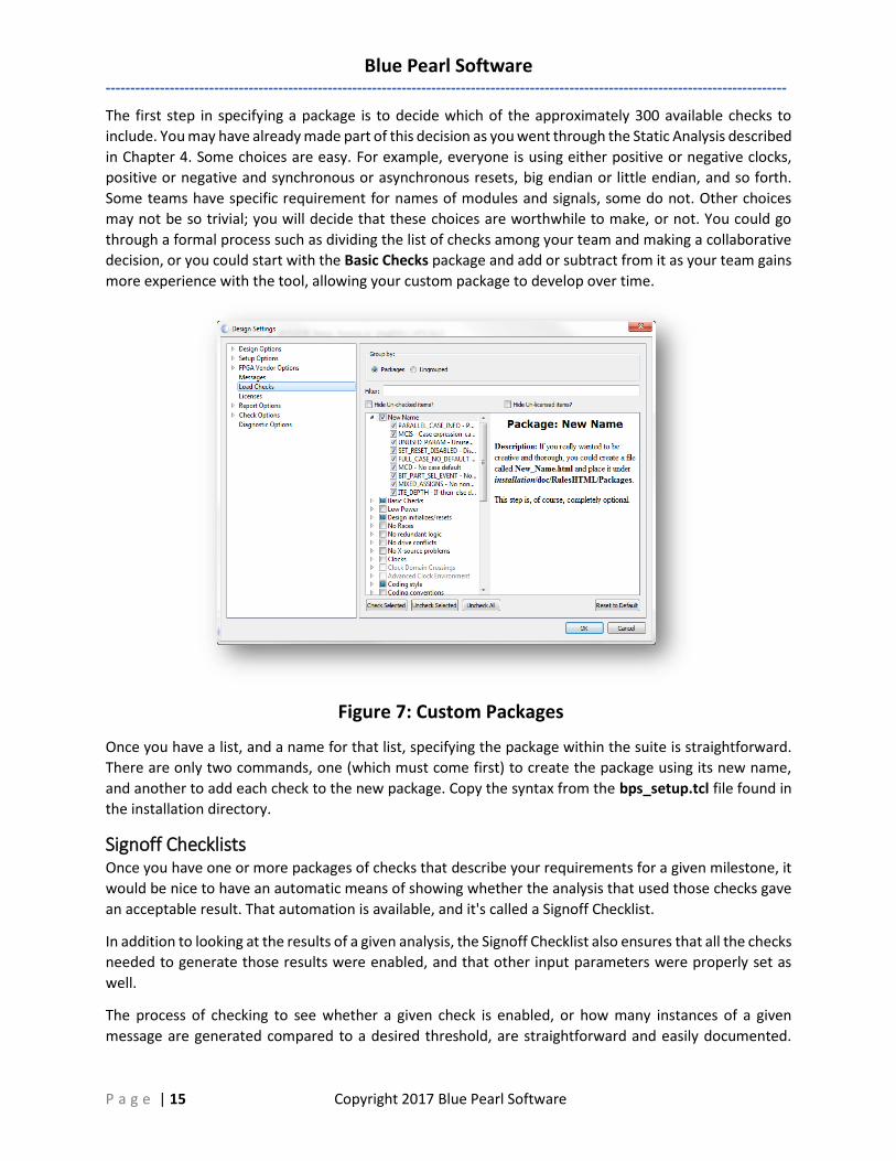
The first step in specifying a package is to decide which of the approximately 300 available checks to
include. You may have already made part of this decision as you went through the Static Analysis described
in Chapter 4. Some choices are easy. For example, everyone is using either positive or negative clocks,
positive or negative and synchronous or asynchronous resets, big endian or little endian, and so forth.
Some teams have specific requirement for names of modules and signals, some do not. Other choices
may not be so trivial; you will decide that these choices are worthwhile to make, or not. You could go
through a formal process such as dividing the list of checks among your team and making a collaborative
decision, or you could start with the Basic Checks package and add or subtract from it as your team gains
more experience with the tool, allowing your custom package to develop over time.
Figure 7: Custom Packages
Once you have a list, and a name for that list, specifying the package within the suite is straightforward.
There are only two commands, one (which must come first) to create the package using its new name,
and another to add each check to the new package. Copy the syntax from the bps_setup.tcl file found in
the installation directory.
Signoff Checklists Once you have one or more packages of checks that describe your requirements for a given milestone, it
would be nice to have an automatic means of showing whether the analysis that used those checks gave
an acceptable result. That automation is available, and it's called a Signoff Checklist.
In addition to looking at the results of a given analysis, the Signoff Checklist also ensures that all the checks
needed to generate those results were enabled, and that other input parameters were properly set as
well.
The process of checking to see whether a given check is enabled, or how many instances of a given
message are generated compared to a desired threshold, are straightforward and easily documented.
Blue Pearl Software
------------------------------------------------------------------------------------------------------------------------------------------
P a g e | 16 Copyright 2017 Blue Pearl Software
There is no need for the user to describe what's being checked or to specify how to check it or what
message to write if a violation occurs. On the other hand, the process of specifying how to verify any of
the hundreds of different input parameters is anything but easy. The user does need to describe the
criterion, name it, specify it precisely using a Tcl expression, and compose a failure message.
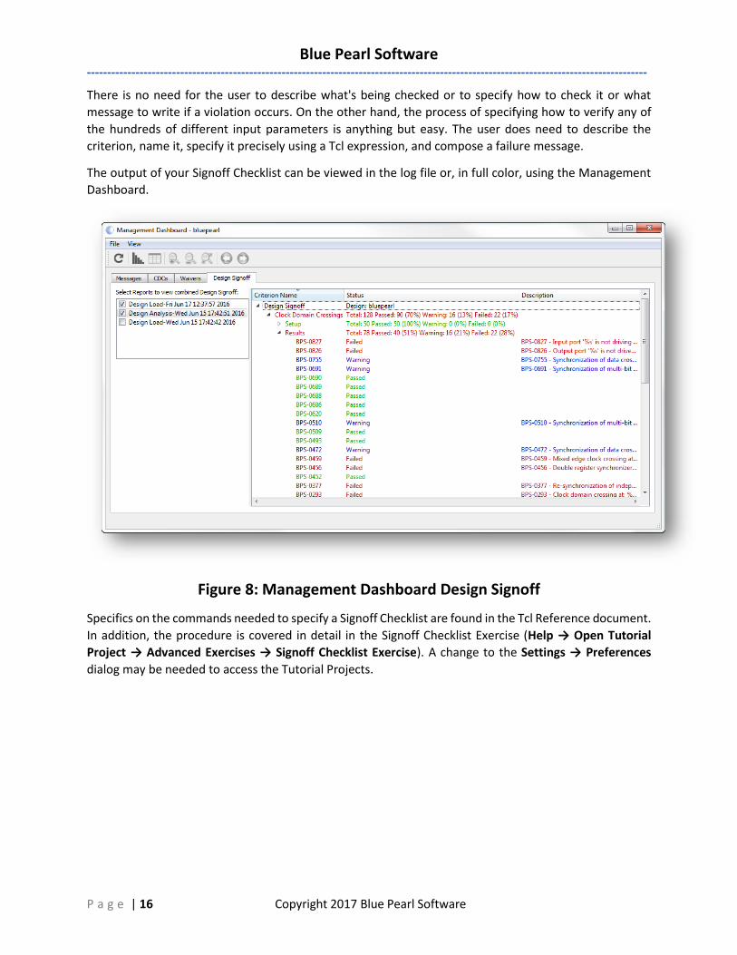
The output of your Signoff Checklist can be viewed in the log file or, in full color, using the Management
Dashboard.
Figure 8: Management Dashboard Design Signoff
Specifics on the commands needed to specify a Signoff Checklist are found in the Tcl Reference document.
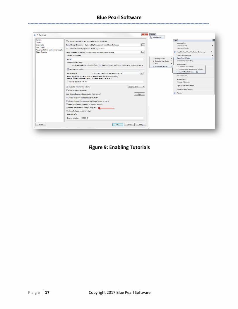
In addition, the procedure is covered in detail in the Signoff Checklist Exercise (Help → Open Tutorial
Project → Advanced Exercises → Signoff Checklist Exercise). A change to the Settings → Preferences
dialog may be needed to access the Tutorial Projects.
Blue Pearl Software
------------------------------------------------------------------------------------------------------------------------------------------
P a g e | 17 Copyright 2017 Blue Pearl Software
Figure 9: Enabling Tutorials
Blue Pearl Software
------------------------------------------------------------------------------------------------------------------------------------------
P a g e | 18 Copyright 2017 Blue Pearl Software
CHAPTER 6: ADVANCE STATIC AND CLOCK DOMAIN CROSSING ANALYSIS
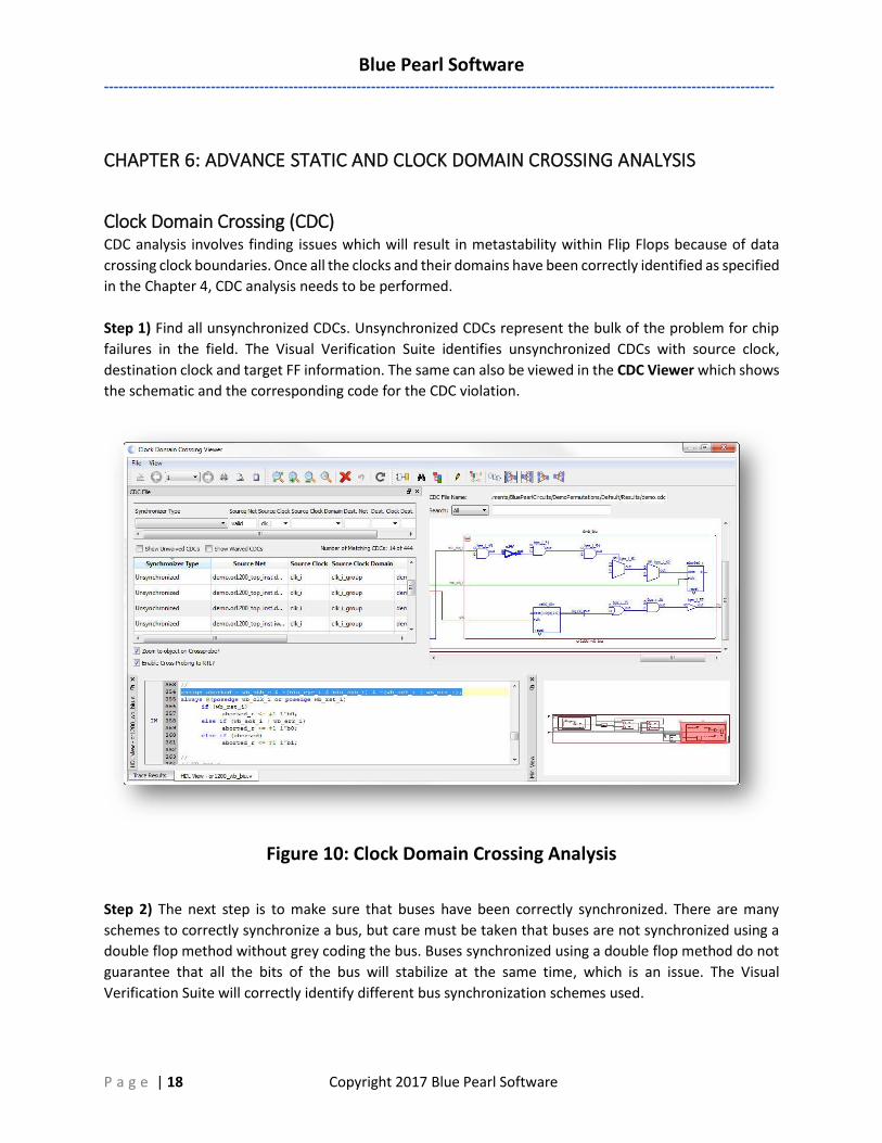
Clock Domain Crossing (CDC) CDC analysis involves finding issues which will result in metastability within Flip Flops because of data
crossing clock boundaries. Once all the clocks and their domains have been correctly identified as specified
in the Chapter 4, CDC analysis needs to be performed.
Step 1) Find all unsynchronized CDCs. Unsynchronized CDCs represent the bulk of the problem for chip
failures in the field. The Visual Verification Suite identifies unsynchronized CDCs with source clock,
destination clock and target FF information. The same can also be viewed in the CDC Viewer which shows
the schematic and the corresponding code for the CDC violation.
Figure 10: Clock Domain Crossing Analysis
Step 2) The next step is to make sure that buses have been correctly synchronized. There are many
schemes to correctly synchronize a bus, but care must be taken that buses are not synchronized using a
double flop method without grey coding the bus. Buses synchronized using a double flop method do not
guarantee that all the bits of the bus will stabilize at the same time, which is an issue. The Visual
Verification Suite will correctly identify different bus synchronization schemes used.
Blue Pearl Software
------------------------------------------------------------------------------------------------------------------------------------------
P a g e | 19 Copyright 2017 Blue Pearl Software
Step 3) Data Reconvergence is a big issue, where data from the same source is synchronized separately
and then converges to a common point some cycles later. This problem is hard to find even in simulation
and can lead to glitch propagation. CDC analysis in the Visual Verification Suite will help identify
reconvergence issues in a design.
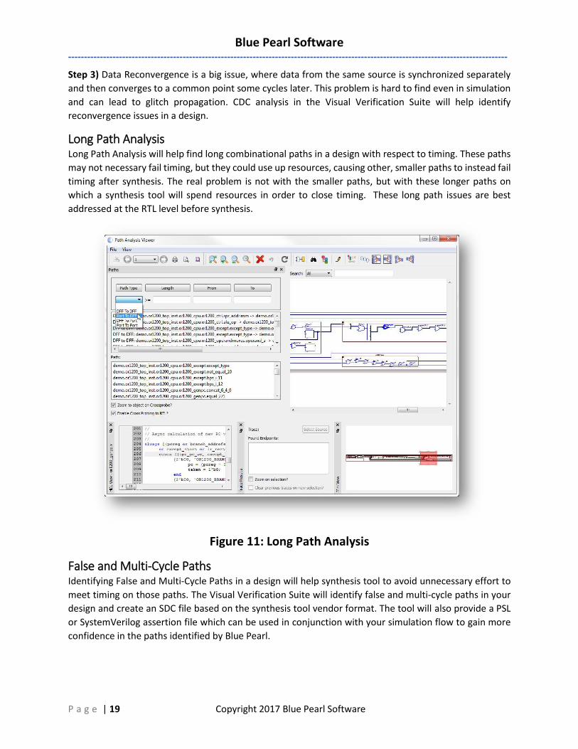
Long Path Analysis Long Path Analysis will help find long combinational paths in a design with respect to timing. These paths
may not necessary fail timing, but they could use up resources, causing other, smaller paths to instead fail
timing after synthesis. The real problem is not with the smaller paths, but with these longer paths on
which a synthesis tool will spend resources in order to close timing. These long path issues are best
addressed at the RTL level before synthesis.
Figure 11: Long Path Analysis
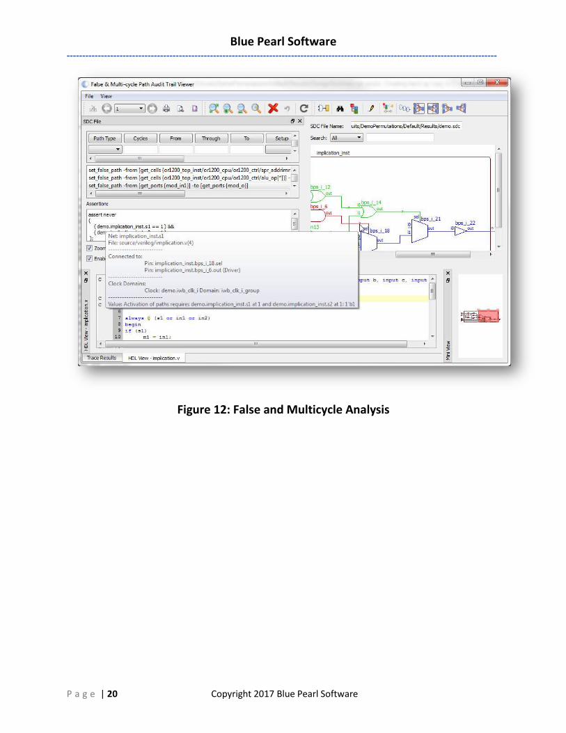
False and Multi-Cycle Paths Identifying False and Multi-Cycle Paths in a design will help synthesis tool to avoid unnecessary effort to
meet timing on those paths. The Visual Verification Suite will identify false and multi-cycle paths in your
design and create an SDC file based on the synthesis tool vendor format. The tool will also provide a PSL
or SystemVerilog assertion file which can be used in conjunction with your simulation flow to gain more
confidence in the paths identified by Blue Pearl.
Blue Pearl Software
------------------------------------------------------------------------------------------------------------------------------------------
P a g e | 20 Copyright 2017 Blue Pearl Software
Figure 12: False and Multicycle Analysis
Blue Pearl Software
------------------------------------------------------------------------------------------------------------------------------------------
P a g e | 21 Copyright 2017 Blue Pearl Software
Chapter 7: Leveraging the Visual Verification Suite in Your Environment
Leveraging Revision Control Systems with the Visual Verification Suite
Projects may involve multiple team members with distributed responsibilities, such as sub-module design, device and system integration, verification, and timing closure. In such cases, it may be useful to track and protect file revisions in an external revision control system. The Visual Verification Suite does not have native integration with any specific version control system. Instead, it is designed to work with all version control systems.
External revision control supports design file version experimentation through branching and merging different versions of source code from multiple designers. Refer to your external revision control documentation for setup information.
Version Control Recommendations for the Visual Verification Suite:
In addition to your RTL project source files, to recreate an analysis run we recommend that the following files, written by the GUI into the Results directory, are stored in your revision control system
• bluepearl.runme.tcl
• Project_Name.settings.tcl
• Project_Name.bluepearlgenerated.f
Running in command line mode as shown below will recreate the following databases required for analysis in the Visual Verification Suite:
• Bluepearl.bpsvdb – the blue pearl visual data base
• Modinfo.db – the database for the design
• Results.db – the database with the static analysis results
Command Line Interface (CLI): >BluePearlCLI –f Project_Name.bluepearlgenerated.f
This will run the Visual Verification Suite in command line mode to restore the project using the options stored in the Project_Name.settings.tcl file. Please note that the two files that start with Project_Name are generated with explicit path references that may need to be edited. Relative path references are allowed.
After the analysis, has been run, the bluepearl.runme.tcl script has a call to “exit” the Tcl shell. Users can edit this out if they wish to continue interactively with analysis and debug after restoring the project.
Blue Pearl Software
------------------------------------------------------------------------------------------------------------------------------------------
P a g e | 22 Copyright 2017 Blue Pearl Software
Optional Setup
Because the suite can be configured to run different features, we recommend having different directories for these options,
• e.g. if the Analysis is configured for Long Path Analysis only. In the Project_Name. bluepearlgenerated.f file, modify the output directory to have the name: Results_LP
• For just a CDC run, you have the directory become: Results_CDC
This, of course, is up to the discretion of the user.
The waivers.xml file is a database of sorts. It contains all the waivers and their timestamp/owner combinations. This file may be source code controlled because it can be manually and graphically edited, thus changing results reported by the tool. It is also possible to use multiple waivers files simultaneously, so that different groups or designers can keep separate waivers files that can be configured to work both on submodules and the entire design.
Using Revision Control Systems and the Visual Verification Suite to Prevent Structural
Issues
When running a revision control system like Jenkins, it is possible to set it up to automatically run the Visual Verification Suite as a mandatory step prior to making source RTL changes. This will prevent structural RTL errors from entering the Simulation scripts.
Additionally, it is also possible to set up to run prior to simulation. If no new messages are found, then simulation is called.
Both flows are for CLI runs. When running the GUI, it comes down to best practices, and either way, analysis before simulation is an essential best practice.
Recommended