06/14 EINS 516325
DESN 516328
PLEASE READ THESE INSTRUCTIONS BEFORE INSTALLING THIS APPLIANCE
Brandon 80 CD C/F
InstallationInstructions
Contents
SECTION CONTENTS PAGE
CONSUMER PROTECTION 3
HEALTH & SAFETY 3
APPLIANCE SPECIFICATION 4
TECHNICAL DATA 5
SITE REQUIREMENTS INTRODUCTION 6
REGULATIONS 6
LOCATION 7
OIL PIPE LINE 8
OIL STORAGE 8
FLUE SYSTEM 9
TYPICAL CHIMNEY INSTALLATION 10
TYPICAL EXTERNAL FLUE SYSTEM 11
AIR SUPPLY 12
WATER CIRCULATION SYSTEM 13
HEATING CONTROLS 13
ELECTRICAL SUPPLY 14
WIRING DIAGRAM - INDEPENDENT SATRONIC BOXES 15
INSTALLATION CLEARANCES 16
REQUIREMENTS PRELIMINARY INSTALLATION 16
SITE LOCATION 17
BAFFLES 18
OIL CONNECTION 19
BURNER ACCESS 20
ELECTRICAL CONNECTION 20
OIL PUMP 20
COMMISSIONING TERMINAL STRIP CONNECTION 21
INSTRUCTIONS ELECTRICAL CHECK 21
FIT PRESSURE GAUGE 22
VENT OIL PUMP 22
ADJUST OIL PRESSURE 22
SET COMBUSTION - BOILER 23
SET COMBUSTION - COOKER 24
ANCILLARY CONTROLS CHECK 25
BOILER CONTROL CHECK 25
INSTRUCT THE USER 25
SEALED SYSTEM SEALED SYSTEM REQUIREMENTS 26
COMMISSIONING 26
TYPICAL OPEN VENTED SYSTEM 27
INSTALLATION CONDENSATE DISPOSAL 28
INSTRUCTIONS CONDENSATE TRAP 28
CONDENSATE SOAKAWAY 29
BRANDON OIL - INSTALLATION CHECKLIST 30
2
Consumer Protection
As responsible manufacturers we take care to make sure that our products are designed and
constructed to meet the required standards when properly installed and used.
IMPORTANT NOTICE: PLEASE READ THE ACCOMPANYING WARRANTY
Any alteration that is not approved by Waterford Stanley could invalidate the approval of the
appliance, operation of the warranty and could affect your statutory rights.
Health & Safety
This appliance may contain some of the materials that are indicated. It is the Users/Installers
responsibility to ensure that the necessary personal protective clothing is worn when handling
where applicable, the pertinent parts that contain any of the listed materials that could be
interpreted as being injurious to health and safety, see below for information.
Firebricks, Fuel beds, Artificial Fuels
When handling use disposable gloves.
Fire cement
When handling use disposable gloves.
Glues and Sealants
Exercise caution - if these are still in liquid form use face mask and disposable gloves.
Glass Yarn, Mineral Wool, Insulation Pads, Ceramic Fibre
Maybe harmful if inhaled. May be irritating to skin, eyes nose and throat. When handling avoid
contact with skin or eyes. Use disposable gloves, face-masks and eye protection. After handling
wash hands and other exposed parts. When disposing of the product, reduce dust with water
spray, ensure that parts are securely wrapped.
Kerosene and Gas Oil (Mineral Oils)
1. The effect of mineral oils on the skin vary according to the duration of the exposure.
2. The lighter fractions also remove the protective grease normally present on the surface of the
skin. This renders the skin dry and more prone to damage caused by cuts and abrasions.
3. ‘Oil acne’ is recognised by the presence of skin rashes. The arms are most often affected,
but may occur where there is contact with oil or oily clothing.
- Seek medical attention for any rash.
- Avoid skin contact with mineral oil or clothing contaminated with mineral oil.
4. Inhalation of mineral oil vapours must be avoided. Never fire the burner in the open as
unburnt oil vapours are likely to occur.
5. Use a suitable barrier cream which will give protection against mineral oil, lanolin based hand
creams are usually very effective.
6. Never syphon mineral oil by use of the mouth. If accidentally swallowed, call a doctor, do not
induce vomiting.
NOTE: SMOKE/SMELL EMITTED DURING INITIAL USAGE
Some parts of the cooker have been coated with a light covering of protective oil. During initial
operation of the cooker, this may cause smoke/smell to be emitted and is normal and not a fault
with the appliance, it is therefore advisable to open doors and or windows to allow for ventilation.
Lift the lids to prevent staining the linings.
3
4
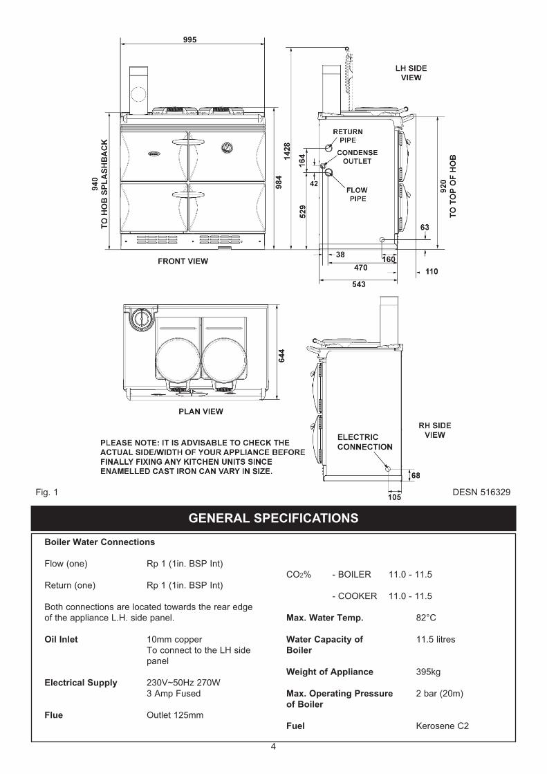
Boiler Water Connections
Flow (one) Rp 1 (1in. BSP Int)
Return (one) Rp 1 (1in. BSP Int)
Both connections are located towards the rear edge
of the appliance L.H. side panel.
Oil Inlet 10mm copper
To connect to the LH side
panel
Electrical Supply 230V~50Hz 270W
3 Amp Fused
Flue Outlet 125mm
CO2% - BOILER 11.0 - 11.5
- COOKER 11.0 - 11.5
Max. Water Temp. 82°C
Water Capacity of 11.5 litres
Boiler
Weight of Appliance 395kg
Max. Operating Pressure 2 bar (20m)
of Boiler
Fuel Kerosene C2
GENERAL SPECIFICATIONS
DESN 516329Fig. 1
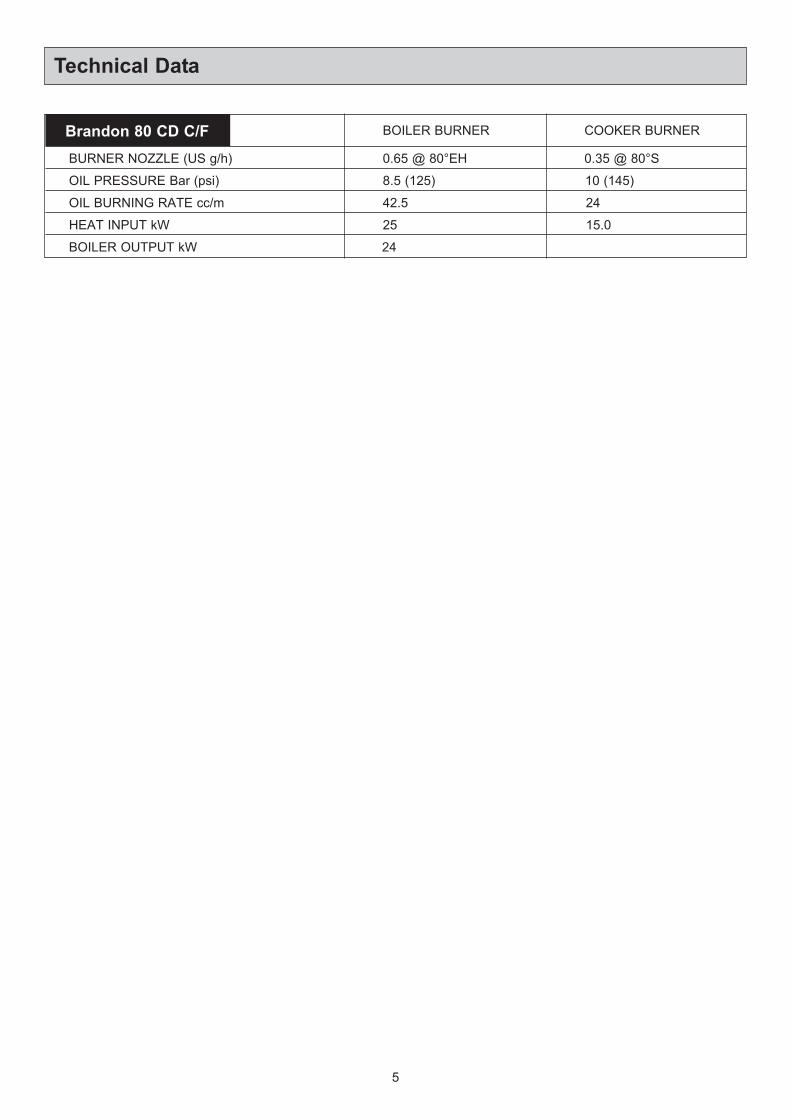
Technical Data
5
BOILER BURNER
BURNER NOZZLE (US g/h) 0.65 @ 80°EH 0.35 @ 80°S
10 (145)
24
15.0
8.5 (125)
42.5
25
24
OIL PRESSURE Bar (psi)
OIL BURNING RATE cc/m
HEAT INPUT kW
BOILER OUTPUT kW
Brandon 80 CD C/F COOKER BURNER
The Stanley Brandon is a floor standing combined cooker
and central heating boiler. It gives independent operation
of space heating, domestic hot water and cooking.
The appliance is fired by two independent pressure jet oil
burners. Either burner can be independently operated
under the programmer control if required.
The boiler is designed for use on a fully pumped low
pressure hot water circulation system with a pumped over
run facility or alternatively on a sealed system limited to 2
bar.
IMPORTANT
l This appliance must only be used with Kerosene
C2 to BS 2869.
l An Indirect Cylinder to BS 1566; Part 1 must be
fitted.
l If the heating circuits are controlled in such a way
that both heating and cylinder circuits can be
closed off at the same time then a BYPASS LOOP
should be fitted. (See Fig. 20).
l An OFTEC approved Fire Valve MUST be fitted in
the oil supply line.
l The supplied in line filter MUST be fitted.
l Permanent ventilation must be provided.
THIS APPLIANCE IS A CONTROLLED SERVICE BY
DEFINITION AND REQUIRES EITHER FITMENT
UNDER THE REMIT OF BUILDING CONTROL OR
INSTALLATION OF AN OFTEC REGISTERED 105
TECHNICIAN (CLASSED AS A COMPETENT PERSON)
WHO CAN SELF CERTIFY HIS OWN WORKS.
This appliance must be commissioned by a Stanley
Approved Engineer. Once the installation has been
completed contact the Waterford Stanley Service
Department on 051-302333 to arrange the commission of
same. Please have the serial number of the cooker
available.
The installation of the appliance must be in accordance
with the relevant requirements of the current Building
Regulations in force and the bylaws of the local Water
Undertaking, it should also be in accordance with the
relevant current British Standard Codes of Practice.
BS5410 - Installation of oil fired appliances for space
heating and hot water supply purpose. Part 1 Boiler of
rated output not exceeding 45kW.
BS5449 - Central Heating for domestic purposes, Part 1.
Forced circulation hot water system.
Building Regulations England and Wales. Part J. Heat
producing appliances.
Building Standards Scotland - Technical Standard Part
F. Heat producing appliances and storage of liquid and
gaseous fuel.
Building Regulations - Technical Booklet to Part L. Heat
producing appliances.
The Control of Oil Pollution (Oil) Regulations.
Site requirements
6
REGULATIONSINTRODUCTION
LOCATION
7
Appliance Hearth: The surface temperature of the floor
below the appliance does not exceed 100°C. The
constructional hearth described in Section J does not
apply. However, this appliance must be installed on a
solid floor of incombustible material which is capable of
supporting the total weight.
The location chosen for the appliance must permit the
installation and the provision of a satisfactory flue and an
adequate air supply. The location must also provide
adequate space for servicing and for air circulation
around the appliance. See “Installation of the Appliance”.
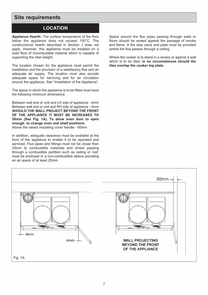
The space in which the appliance is to be fitted must have
the following minimum dimensions:
Between wall and or unit and LH side of appliance - 4mm
Between wall and or unit and RH side of appliance - 4mm
SHOULD THE WALL PROJECT BEYOND THE FRONT
OF THE APPLIANCE IT MUST BE INCREASED TO
50mm (See Fig. 1A). To allow oven door to open
enough to change oven and shelf positions.
Above the raised insulating cover handle - 60mm
In addition, adequate clearance must be available at the
front of the appliance to enable it to be operated and
serviced. Flue pipes and fittings must not be closer than
25mm to combustible materials and where passing
through a combustible partition such as ceiling or roof,
must be enclosed in a non-combustible sleeve providing
an air space of at least 25mm.
Site requirements
Space around the flue pipes passing through walls or
floors should be sealed against the passage of smoke
and flame. A fire stop valve and plate must be provided
where the flue passes through a ceiling.
Where the cooker is to stand in a recess or against a wall
which is to be tiled, in no circumstances should the
tiles overlap the cooker top plate.
Fig. 1A
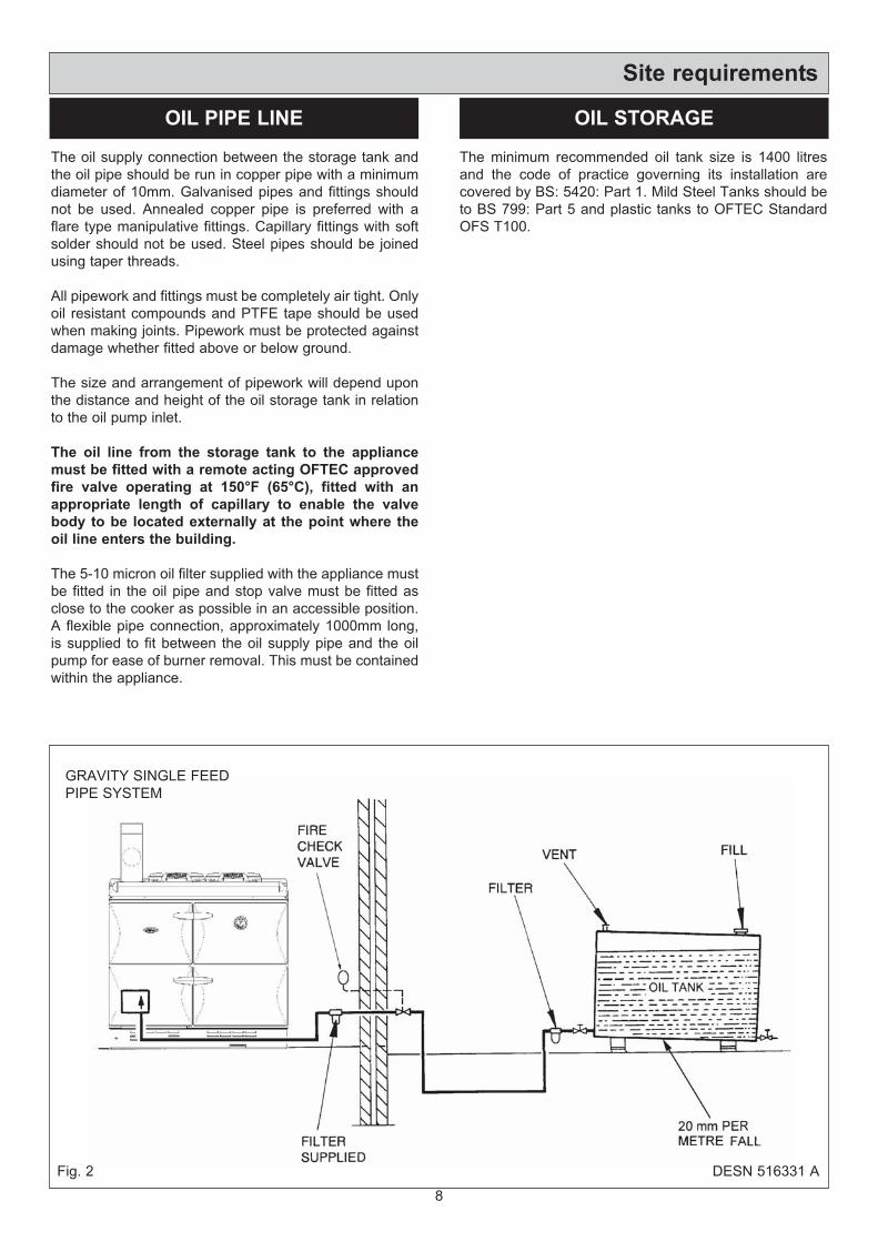
The oil supply connection between the storage tank and
the oil pipe should be run in copper pipe with a minimum
diameter of 10mm. Galvanised pipes and fittings should
not be used. Annealed copper pipe is preferred with a
flare type manipulative fittings. Capillary fittings with soft
solder should not be used. Steel pipes should be joined
using taper threads.
All pipework and fittings must be completely air tight. Only
oil resistant compounds and PTFE tape should be used
when making joints. Pipework must be protected against
damage whether fitted above or below ground.
The size and arrangement of pipework will depend upon
the distance and height of the oil storage tank in relation
to the oil pump inlet.
The oil line from the storage tank to the appliance
must be fitted with a remote acting OFTEC approved
fire valve operating at 150°F (65°C), fitted with an
appropriate length of capillary to enable the valve
body to be located externally at the point where the
oil line enters the building.
The 5-10 micron oil filter supplied with the appliance must
be fitted in the oil pipe and stop valve must be fitted as
close to the cooker as possible in an accessible position.
A flexible pipe connection, approximately 1000mm long,
is supplied to fit between the oil supply pipe and the oil
pump for ease of burner removal. This must be contained
within the appliance.
The minimum recommended oil tank size is 1400 litres
and the code of practice governing its installation are
covered by BS: 5420: Part 1. Mild Steel Tanks should be
to BS 799: Part 5 and plastic tanks to OFTEC Standard
OFS T100.
Site requirements
8
OIL PIPE LINE OIL STORAGE
GRAVITY SINGLE FEED
PIPE SYSTEM
Fig. 2 DESN 516331 A
The flue system must be installed with the regulations in
force.
Maximum flue gas temperature 250°C
(Both burners on)
Minimum flue gas temperature 125°C
(Boiler burner on only)
Chimney Termination
All chimneys should terminate at least 600mm above the
roof level in accordance with current Building Regulations
and statutory requirements as outlined in BS 5410: Part 1,
BS 6461: Part 1 and BS 7566 Parts 1 to 4.
Chimney Cleaning
Ensure there are accessible airtight flue cleaning doors in
order to obtain cleaning access to the complete chimney.
Providing the appliance is operating correctly, an annual
chimney flue cleaning will suffice, but if in doubt arrange
for a half yearly clean, preferably at the beginning/end of
the heating season.
The appliane must only be connected to approved
flue systems. Off the appliance using Schiedel
Ritevent Prima Plus (available in black from
Waterford Stanley), and then either ECO ICID or
Tecno Turbo Flex System.
For further information on Schiedel Ritevent Flue
Systems go to www.schiedel.co.uk
Site requirements
9
FLUE SYSTEM
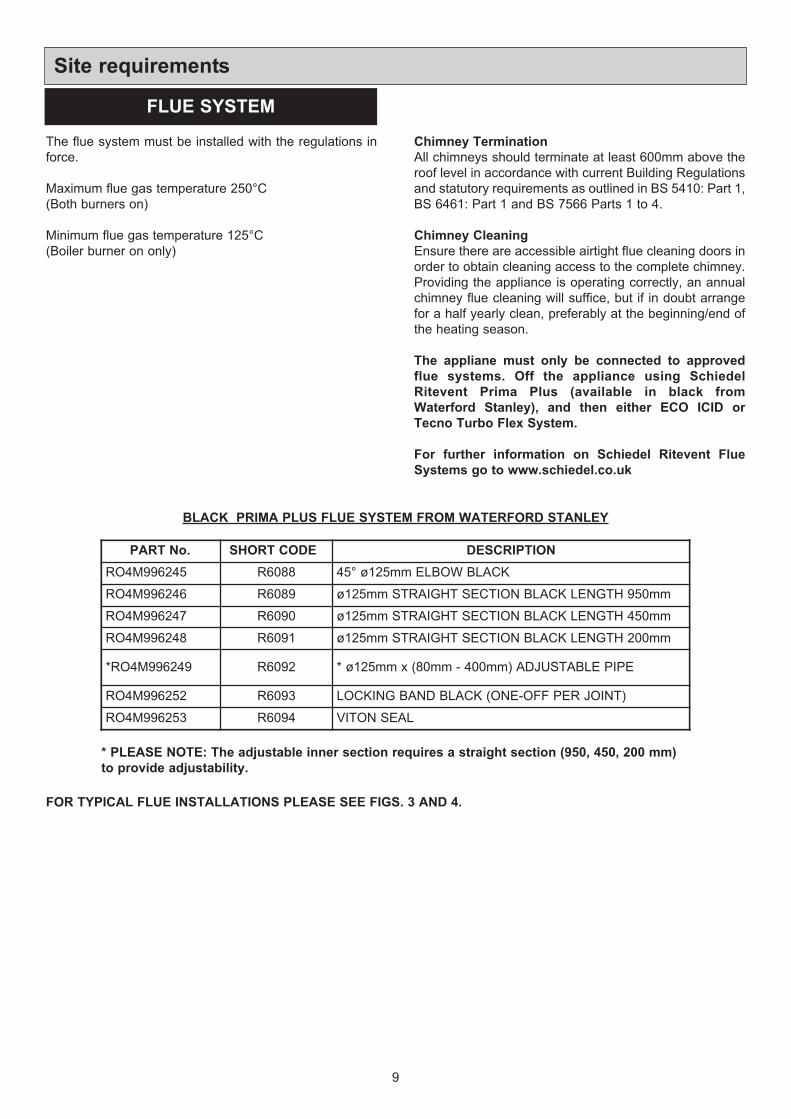
PART No. SHORT CODE DESCRIPTION
RO4M996245 R6088 45° ø125mm ELBOW BLACK
RO4M996246 R6089 ø125mm STRAIGHT SECTION BLACK LENGTH 950mm
RO4M996247 R6090 ø125mm STRAIGHT SECTION BLACK LENGTH 450mm
RO4M996248 R6091 ø125mm STRAIGHT SECTION BLACK LENGTH 200mm
*RO4M996249 R6092 * ø125mm x (80mm - 400mm) ADJUSTABLE PIPE
RO4M996252 R6093 LOCKING BAND BLACK (ONE-OFF PER JOINT)
RO4M996253 R6094 VITON SEAL
BLACK PRIMA PLUS FLUE SYSTEM FROM WATERFORD STANLEY
FOR TYPICAL FLUE INSTALLATIONS PLEASE SEE FIGS. 3 AND 4.
* PLEASE NOTE: The adjustable inner section requires a straight section (950, 450, 200 mm)
to provide adjustability.
10
Site requirements
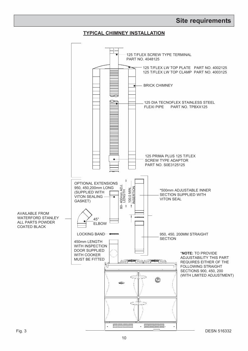
TYPICAL CHIMNEY INSTALLATION
125 T/FLEX SCREW TYPE TERMINAL
PART NO. 4048125
BRICK CHIMNEY
125 DIA TECNOFLEX STAINLESS STEEL
FLEXI PIPE PART NO. TPBXX125
125 PRIMA PLUS 125 T/FLEX
SCREW TYPE ADAPTOR
PART NO. S0E3125125
AVAILABLE FROM
WATERFORD STANLEY
ALL PARTS POWDER
COATED BLACK
OPTIONAL EXTENSIONS
950, 450,200mm LONG
(SUPPLIED WITH
VITON SEALING
GASKET)
45°
ELBOW
LOCKING BAND
450mm LENGTH
WITH INSPECTION
DOOR SUPPLIED
WITH COOKER
MUST BE FITTED
80
- 4
00
mm
AD
J.
LE
NG
TH
10
0.0
MIN
.
INS
ER
TIO
N
Fig. 3 DESN 516332
Site requirements
125 T/FLEX LW TOP PLATE PART NO. 4002125
125 T/FLEX LW TOP CLAMP PART NO. 4003125
*500mm ADJUSTABLE INNER
SECTION SUPPLIED WITH
VITON SEAL
*NOTE: TO PROVIDE
ADJUSTABILITY THIS PART
REQUIRES EITHER OF THE
FOLLOWING STRAIGHT
SECTIONS 900, 450, 200
(WITH LIMITED ADJUSTMENT)
950, 450, 200MM STRAIGHT
SECTION
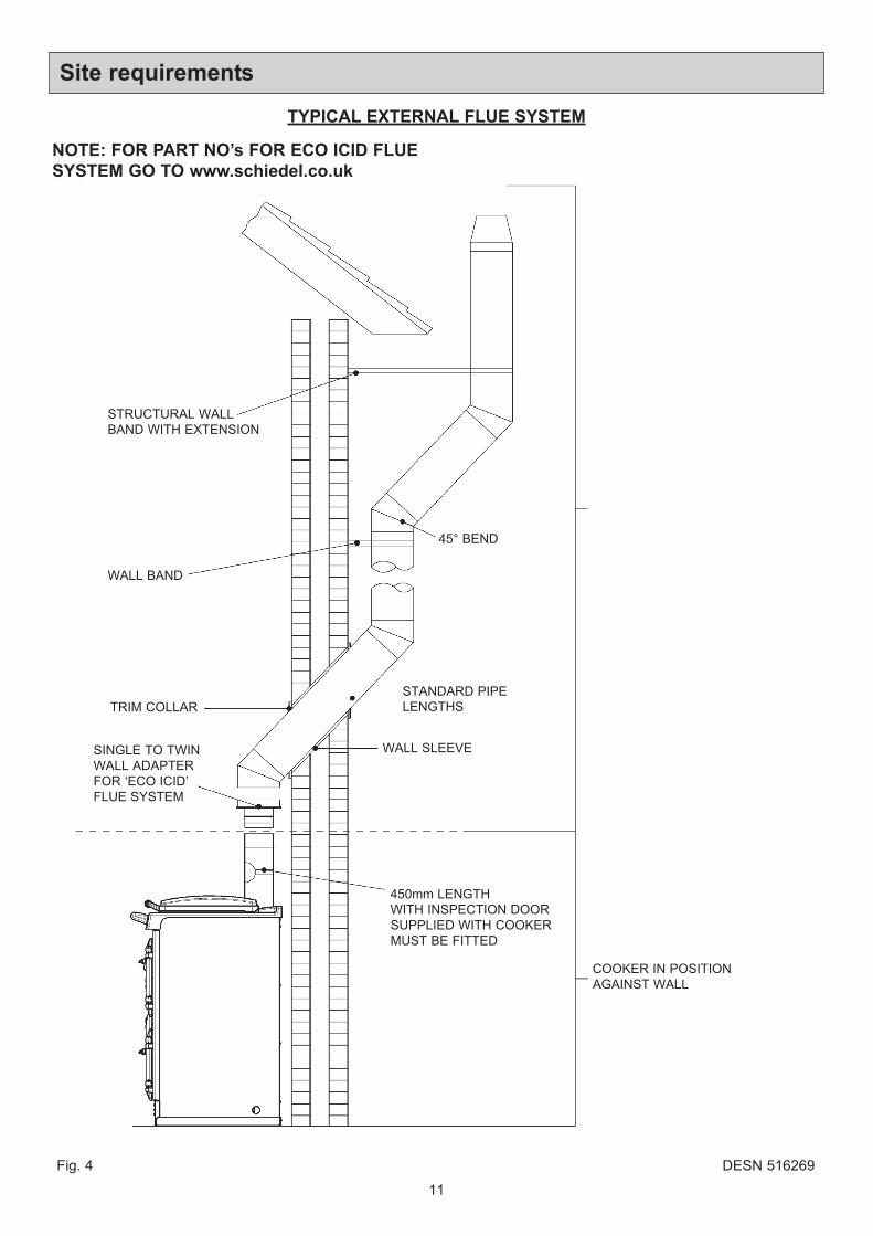
TYPICAL EXTERNAL FLUE SYSTEM
45° BEND
STRUCTURAL WALL
BAND WITH EXTENSION
WALL BAND
TRIM COLLAR
SINGLE TO TWIN
WALL ADAPTER
FOR ‘ECO ICID’
FLUE SYSTEM
STANDARD PIPE
LENGTHS
WALL SLEEVE
450mm LENGTH
WITH INSPECTION DOOR
SUPPLIED WITH COOKER
MUST BE FITTED
COOKER IN POSITION
AGAINST WALL
11
Fig. 4 DESN 516269
Site requirements
NOTE: FOR PART NO’s FOR ECO ICID FLUE
SYSTEM GO TO www.schiedel.co.uk
The appliance can only be installed in a room which
meets the ventilation regulations in force. But, in any
event the room must have a permanent vent of minimum
free air area, see below:
IMPORTANT: THE LOUVERED AIR INTAKE AT THE
BOTTOM FRONT OF THIS APPLIANCE MUST BE
KEPT CLEAR OF ANY OBSTRUCTIONS.
Detailed recommendations for air supply are given in the
Building Regulations and in BS 5410: Part 1. The
following notes are intended to give general guidance.
1. Combustion and ventilation air supply to oil fired
appliance has to comply with the Building Regulations
and with BS 5410: Part 1. The air supply requirement
for oil fired appliance in 550mm2 per kW of maximum
rated output above 5 kW. These requirements are
illustrated in OFTEC Technical Book No. 3.
2. The combustion air supply to open flued appliances
should normally be provided at high level into a room
where it will not cause discomfort by creating a cold
draught across the floor.
3. If combustion air is supplied through an under floor
duct the grilles at each end should be positioned in the
vertical plane to reduce the risk of blockage. Ducts
should be sized so as to reduce the resistance to air
flow.
4. The ventilation requirement for kitchen in Part F of the
Building Regulations (England & Wales) is for
mechanical extract at the rate of 60 litres per second
or 30 litres if the fan is incorporated in a cooker hood.
The amount can be reduced if the spillage of flue
gases might be caused by the outflow of air from the
room.
Background ventilation is also required, either by
producing a constant extract rate of one air change per
hour or by having ventilation openings of not less than
4000m2.
5. Extract fan should be positioned as far away from the
open flue as possible and should have a sufficient
dedicated air supply. To undertake a test the oil fired
appliance should be set in operation and the doors and
windows of the room containing it should be closed.
The extract fan should then be run at its maximum
setting. The oil fired heating appliance should be
observed to operate satisfactorily both before and after
the fan is switched on.
6. It is preferable for the air supply for an extract fan to be
located where it can serve the fan without the air
stream passing close to the oil fired appliance.
7. Oil fired appliances must not draw the combustion air
from a garage.
12
Site requirements
AIR SUPPLY
680KCD O/F 180cm2
MODEL MIN. AIR REQUIREMENT
Flow and return pipework between cooker and zone
valves must be 28mm diameter minimum.
Space and water heating should be in accordance with
the relevant recommendations of BS 5410: Part 1.
In a combined central heating and domestic hot water
system, the hot water storage vessel must be of the
indirect cylinder type to BS 1566: Part 1. The hot water
storage vessel should be insulated with not less than
75mm thick mineral fibre or its equivalent.
Cisterns and pipework should not be situated in areas
which maybe exposed by freezing conditions.
Draining taps must be located in accessible positions
which permit the draining of the whole system, including
the heat storage vessel. Draining taps should be at least1/2in BSP nominal size and be in accordance with BS
2879.
The appliance boiler section should be connected to a
cistern water supply, subject to a maximum head of
18.25m.
Alternatively a ‘sealed’ system may be used with an
appropriately sized expansion vessel and the pressure
relief valve is limited to 2 bar, See Page 26.
The heating system must be designed (and adjusted if
necessary) to give temperature differential across the
boiler at full output of 10-14°C. When horizontal runs are
used the pipes should rise upwards in the direction away
from the appliance.
Circulating Pump
It is recommended that the selected pump be sized to suit
the boiler pressure loss and therefore adequate to give
the required temperature differential between the flow and
return.
The pump should be able to meet the requirements of the
system design and fitted in a readily accessible position.
Isolating Valves
Isolating valves (preferably of the keyless type) must be
fitted to the inlet and outlet of the circulating pump to
facilitate service and replacement of pump without
draining the system.
Inhibitor
A corrosion inhibitor MUST be added to the heating
system to protect the heat exchanger and pipework.
Inhibitor must also be replaced if the system is drained
after installation. As a precaution the heating system
MUST also be flushed out prior to the addition of the
inhibitor to ensure any flux, debris is removed.
Independent temperature controls with time switch control
are recommended for providing temperature comfort from
radiators.
Typical controls can be motorised valves operated by
room thermostat and cylinder thermostat.
Thermostatic radiator valves may be fitted when required.
The boiler should be controlled so that it operates on
demand only.
Operation of the system under control of the boiler
thermostat only, does not produce the best efficiency.
Refer to the control equipment manufacturers literature
for information e.g. wiring.
Site requirements
13
WATER CIRCULATION SYSTEM HEATING CONTROLS
Wiring external to the appliance must be installed in
accordance with current National Wiring Regulations and
any local regulations which apply. The appliance is
supplied for 230 Volt ~ 50 Hz 270W a fuse rating of 3
amps. The method of connection to the mains supply
should facilitate complete isolation of the appliance, by
the use of a fused double pole switch having contact
separation of at least 3mm serving only the appliance.
The point of connection to the mains should be readily
accessible and adjacent to the appliance. The installation
should be protected by a 30 mA Residual Current Circuit
Breaker (RCCB).
The minimum requirement for the power cable is that it
should be a 3 core PVC sheathed flexible cord (85°C min)
at least 0.75mm2 (24 x 0.2mm) to the relevant standard.
WARNING: THIS APPLIANCE MUST BE EARTHED.
In the event of an electrical fault after installation of the
appliance, preliminary electrical system checks must be
carried out i.e. earth continuity, polarity and resistance to
earth.
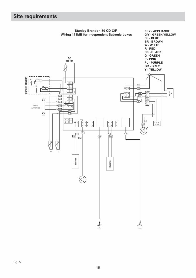
For wiring instructions, see wiring diagrams.
The circulating pump must be connected to PL and PN on
the terminal block (See Fig. 4) and the cables clamped
and passed through the grommet in the right hand side
panel.
NOTE: The 3 amp fuse rating takes into account any
AUXILIARY components used. In most central heating
systems i.e. circulation pump, zone valves. Waterford
Stanley recommend that only CE marked equipment is
used in conjunction with this appliance.
14
Site requirements
ELECTRICAL SUPPLY
15
Site requirements
Fig. 5
Stanley Brandon 80 CD C/F
Wiring 111MB for independent Satronic boxes
The appliance is floor mounted. The space in which the
appliance is to be fitted must have the following minimum
dimensions.
Between wall or unit and LH side of appliance - 4mm
Between wall or unit and RH side of appliance - 4mm
SHOULD THE WALL PROJECT BEYOND THE FRONT
OF THE APPLIANCE, IT MUST BE INCREASED TO
50mm (See Fig. 1A). To allow oven door to open
enough to change the oven and shelf positions.
Above the raised insulating cover handle - 60mm
In addition adequate clearance must be available at the
front of the appliance to enable it to be operated and
serviced.
The appliance is delivered in a fully assembled condition
with the exception of the following items which are
supplied separately packed and require assembly:-
The appliance rear distance bracket
The oil filter
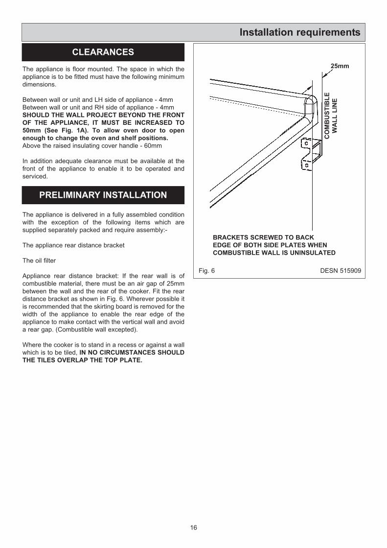
Appliance rear distance bracket: If the rear wall is of
combustible material, there must be an air gap of 25mm
between the wall and the rear of the cooker. Fit the rear
distance bracket as shown in Fig. 6. Wherever possible it
is recommended that the skirting board is removed for the
width of the appliance to enable the rear edge of the
appliance to make contact with the vertical wall and avoid
a rear gap. (Combustible wall excepted).
Where the cooker is to stand in a recess or against a wall
which is to be tiled, IN NO CIRCUMSTANCES SHOULD
THE TILES OVERLAP THE TOP PLATE.
Installation requirements
16
CLEARANCES
PRELIMINARY INSTALLATION
Fig. 6 DESN 515909
BRACKETS SCREWED TO BACK
EDGE OF BOTH SIDE PLATES WHEN
COMBUSTIBLE WALL IS UNINSULATED
CO
MB
US
TIB
LE
WA
LL
LIN
E
25mm
1. Check that the hearth is level, then remove the
appliance from its transit wooden pallet, and position it
with its back against the wall and in its intended
position for flue connection.
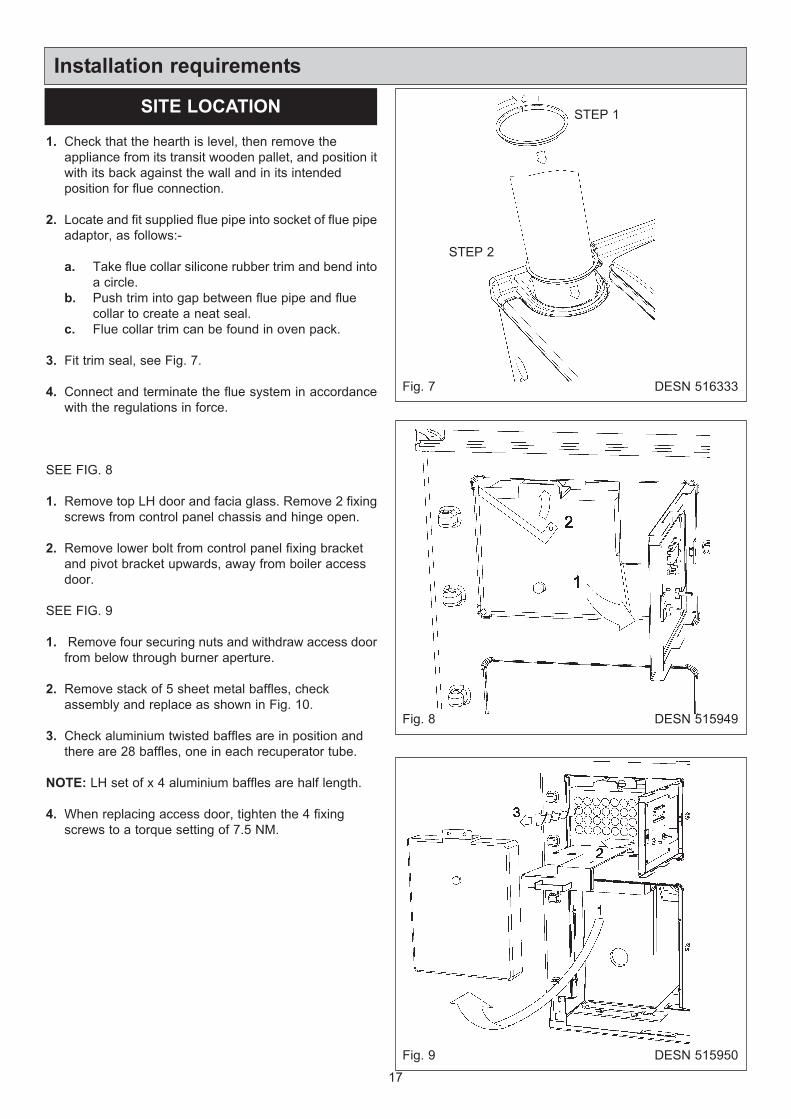
2. Locate and fit supplied flue pipe into socket of flue pipe
adaptor, as follows:-
a. Take flue collar silicone rubber trim and bend into
a circle.
b. Push trim into gap between flue pipe and flue
collar to create a neat seal.
c. Flue collar trim can be found in oven pack.
3. Fit trim seal, see Fig. 7.
4. Connect and terminate the flue system in accordance
with the regulations in force.
SEE FIG. 8
1. Remove top LH door and facia glass. Remove 2 fixing
screws from control panel chassis and hinge open.
2. Remove lower bolt from control panel fixing bracket
and pivot bracket upwards, away from boiler access
door.
SEE FIG. 9
1. Remove four securing nuts and withdraw access door
from below through burner aperture.
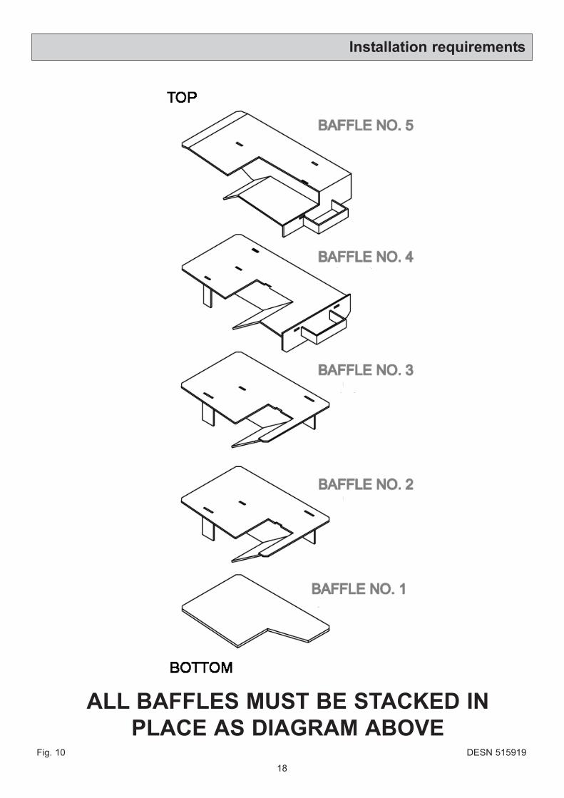
2. Remove stack of 5 sheet metal baffles, check
assembly and replace as shown in Fig. 10.
3. Check aluminium twisted baffles are in position and
there are 28 baffles, one in each recuperator tube.
NOTE: LH set of x 4 aluminium baffles are half length.
4. When replacing access door, tighten the 4 fixing
screws to a torque setting of 7.5 NM.
Installation requirements
17
SITE LOCATION
Fig. 8
Fig. 9
DESN 515949
DESN 515950
STEP 1
STEP 2
Fig. 7 DESN 516333
Installation requirements
18
Fig. 10
ALL BAFFLES MUST BE STACKED IN
PLACE AS DIAGRAM ABOVEDESN 515919
Installation requirements
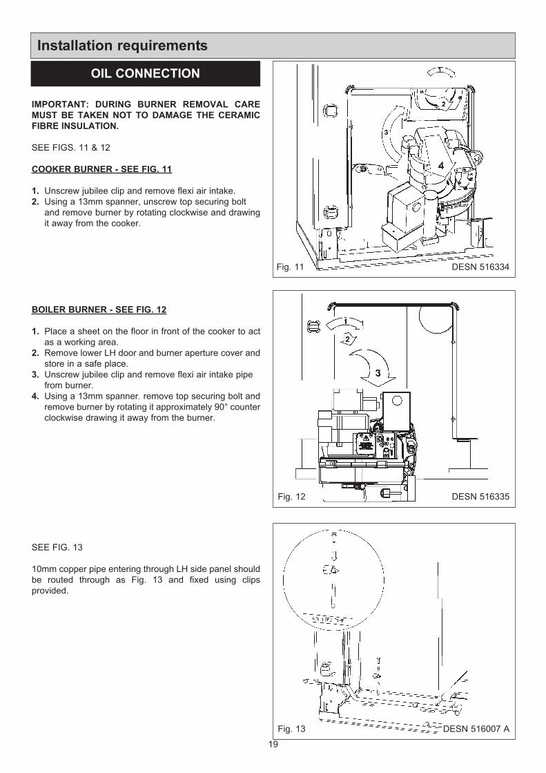
IMPORTANT: DURING BURNER REMOVAL CARE
MUST BE TAKEN NOT TO DAMAGE THE CERAMIC
FIBRE INSULATION.
SEE FIGS. 11 & 12
COOKER BURNER - SEE FIG. 11
1. Unscrew jubilee clip and remove flexi air intake.
2. Using a 13mm spanner, unscrew top securing bolt
and remove burner by rotating clockwise and drawing
it away from the cooker.
BOILER BURNER - SEE FIG. 12
1. Place a sheet on the floor in front of the cooker to act
as a working area.
2. Remove lower LH door and burner aperture cover and
store in a safe place.
3. Unscrew jubilee clip and remove flexi air intake pipe
from burner.
4. Using a 13mm spanner. remove top securing bolt and
remove burner by rotating it approximately 90° counter
clockwise drawing it away from the burner.
SEE FIG. 13
10mm copper pipe entering through LH side panel should
be routed through as Fig. 13 and fixed using clips
provided.
19
OIL CONNECTION
Fig. 11
Fig. 12
DESN 516334
DESN 516335
Fig. 13 DESN 516007 A
20
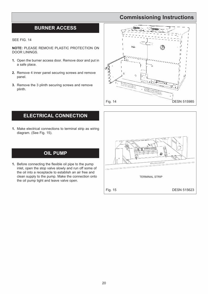
SEE FIG. 14
NOTE: PLEASE REMOVE PLASTIC PROTECTION ON
DOOR LININGS.
1. Open the burner access door. Remove door and put in
a safe place.
2. Remove 4 inner panel securing screws and remove
panel.
3. Remove the 3 plinth securing screws and remove
plinth.
1. Make electrical connections to terminal strip as wiring
diagram. (See Fig. 15).
1. Before connecting the flexible oil pipe to the pump
inlet, open the stop valve slowly and run off some of
the oil into a receptacle to establish an air free and
clean supply to the pump. Make the connection onto
the oil pump tight and leave valve open.
Commissioning Instructions
Fig. 14 DESN 515985
DESN 515623Fig. 15
BURNER ACCESS
OIL PUMP
ELECTRICAL CONNECTION
TERMINAL STRIP
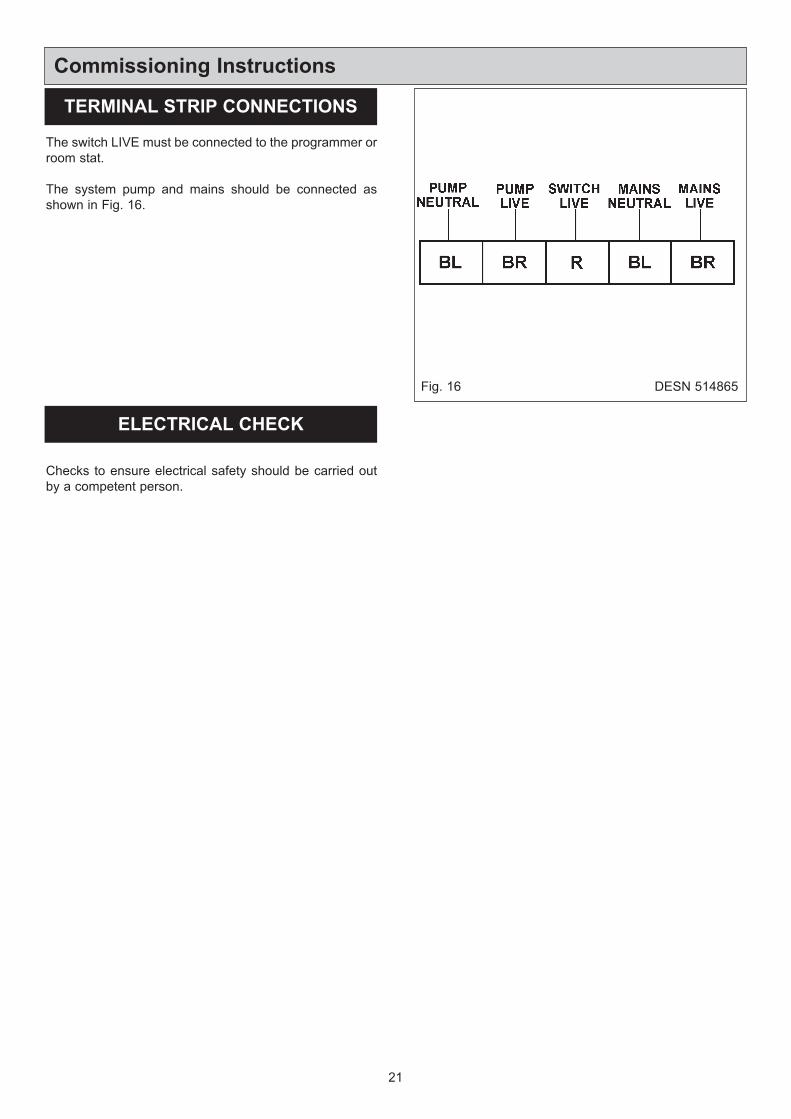
The switch LIVE must be connected to the programmer or
room stat.
The system pump and mains should be connected as
shown in Fig. 16.
Checks to ensure electrical safety should be carried out
by a competent person.
21
Commissioning Instructions
TERMINAL STRIP CONNECTIONS
Fig. 16 DESN 514865
ELECTRICAL CHECK
22
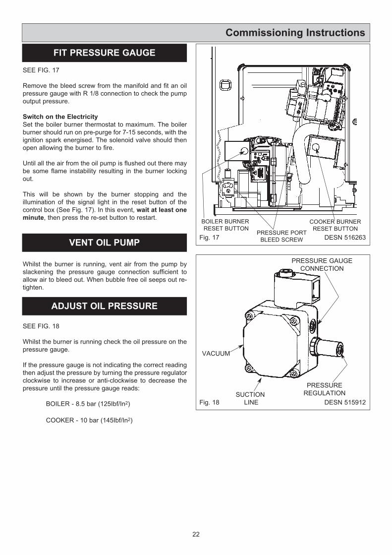
SEE FIG. 17
Remove the bleed screw from the manifold and fit an oil
pressure gauge with R 1/8 connection to check the pump
output pressure.
Switch on the Electricity
Set the boiler burner thermostat to maximum. The boiler
burner should run on pre-purge for 7-15 seconds, with the
ignition spark energised. The solenoid valve should then
open allowing the burner to fire.
Until all the air from the oil pump is flushed out there may
be some flame instability resulting in the burner locking
out.
This will be shown by the burner stopping and the
illumination of the signal light in the reset button of the
control box (See Fig. 17). In this event, wait at least one
minute, then press the re-set button to restart.
Whilst the burner is running, vent air from the pump by
slackening the pressure gauge connection sufficient to
allow air to bleed out. When bubble free oil seeps out re-
tighten.
SEE FIG. 18
Whilst the burner is running check the oil pressure on the
pressure gauge.
If the pressure gauge is not indicating the correct reading
then adjust the pressure by turning the pressure regulator
clockwise to increase or anti-clockwise to decrease the
pressure until the pressure gauge reads:
BOILER - 8.5 bar (125Ibf/In2)
COOKER - 10 bar (145Ibf/In2)
Commissioning Instructions
FIT PRESSURE GAUGE
VENT OIL PUMP
ADJUST OIL PRESSURE
Fig. 17 DESN 516263
BOILER BURNER
RESET BUTTONPRESSURE PORT
BLEED SCREW
COOKER BURNER
RESET BUTTON
DESN 515912Fig. 18
VACUUM
SUCTION
LINE
PRESSURE GAUGE
CONNECTION
PRESSURE
REGULATION
23
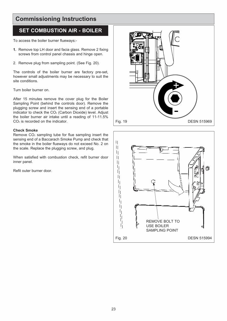
To access the boiler burner flueways:-
1. Remove top LH door and facia glass. Remove 2 fixing
screws from control panel chassis and hinge open.
2. Remove plug from sampling point. (See Fig. 20).
The controls of the boiler burner are factory pre-set,
however small adjustments may be necessary to suit the
site conditions.
Turn boiler burner on.
After 15 minutes remove the cover plug for the Boiler
Sampling Point (behind the controls door). Remove the
plugging screw and insert the sensing end of a portable
indicator to check the CO2 (Carbon Dioxide) level. Adjust
the boiler burner air intake until a reading of 11-11.5%
CO2 is recorded on the indicator.
Check Smoke
Remove CO2 sampling tube for flue sampling insert the
sensing end of a Baccarach Smoke Pump and check that
the smoke in the boiler flueways do not exceed No. 2 on
the scale. Replace the plugging screw, and plug.
When satisfied with combustion check, refit burner door
inner panel.
Refit outer burner door.
Commissioning Instructions
SET COMBUSTION AIR - BOILER
Fig. 19 DESN 515969
DESN 515994Fig. 20
REMOVE BOLT TO
USE BOILER
SAMPLING POINT
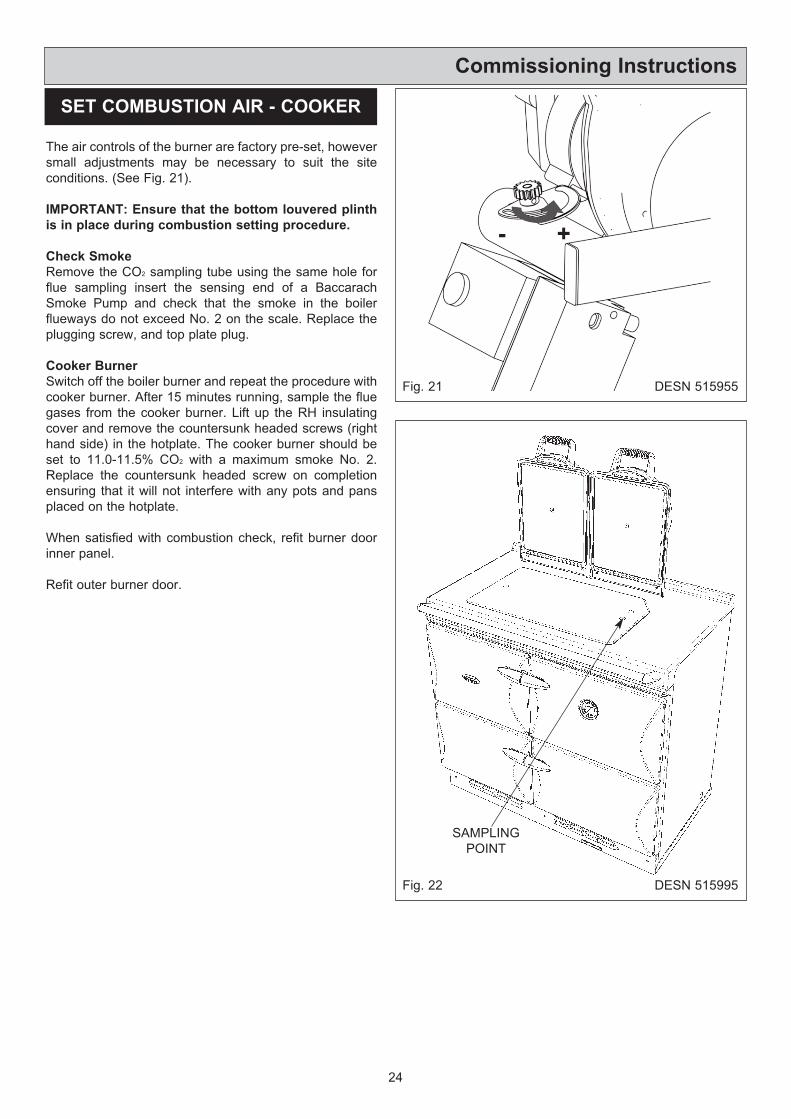
The air controls of the burner are factory pre-set, however
small adjustments may be necessary to suit the site
conditions. (See Fig. 21).
IMPORTANT: Ensure that the bottom louvered plinth
is in place during combustion setting procedure.
Check Smoke
Remove the CO2 sampling tube using the same hole for
flue sampling insert the sensing end of a Baccarach
Smoke Pump and check that the smoke in the boiler
flueways do not exceed No. 2 on the scale. Replace the
plugging screw, and top plate plug.
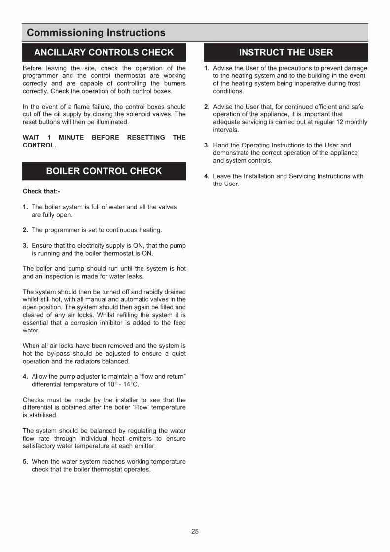
Cooker Burner
Switch off the boiler burner and repeat the procedure with
cooker burner. After 15 minutes running, sample the flue
gases from the cooker burner. Lift up the RH insulating
cover and remove the countersunk headed screws (right
hand side) in the hotplate. The cooker burner should be
set to 11.0-11.5% CO2 with a maximum smoke No. 2.
Replace the countersunk headed screw on completion
ensuring that it will not interfere with any pots and pans
placed on the hotplate.
When satisfied with combustion check, refit burner door
inner panel.
Refit outer burner door.
24
Commissioning Instructions
SET COMBUSTION AIR - COOKER
Fig. 21 DESN 515955
+-
Fig. 22 DESN 515995
SAMPLING
POINT
Before leaving the site, check the operation of the
programmer and the control thermostat are working
correctly and are capable of controlling the burners
correctly. Check the operation of both control boxes.
In the event of a flame failure, the control boxes should
cut off the oil supply by closing the solenoid valves. The
reset buttons will then be illuminated.
WAIT 1 MINUTE BEFORE RESETTING THE
CONTROL.
Check that:-
1. The boiler system is full of water and all the valves
are fully open.
2. The programmer is set to continuous heating.
3. Ensure that the electricity supply is ON, that the pump
is running and the boiler thermostat is ON.
The boiler and pump should run until the system is hot
and an inspection is made for water leaks.
The system should then be turned off and rapidly drained
whilst still hot, with all manual and automatic valves in the
open position. The system should then again be filled and
cleared of any air locks. Whilst refilling the system it is
essential that a corrosion inhibitor is added to the feed
water.
When all air locks have been removed and the system is
hot the by-pass should be adjusted to ensure a quiet
operation and the radiators balanced.
4. Allow the pump adjuster to maintain a “flow and return”
differential temperature of 10° - 14°C.
Checks must be made by the installer to see that the
differential is obtained after the boiler ‘Flow’ temperature
is stabilised.
The system should be balanced by regulating the water
flow rate through individual heat emitters to ensure
satisfactory water temperature at each emitter.
5. When the water system reaches working temperature
check that the boiler thermostat operates.
1. Advise the User of the precautions to prevent damage
to the heating system and to the building in the event
of the heating system being inoperative during frost
conditions.
2. Advise the User that, for continued efficient and safe
operation of the appliance, it is important that
adequate servicing is carried out at regular 12 monthly
intervals.
3. Hand the Operating Instructions to the User and
demonstrate the correct operation of the appliance
and system controls.
4. Leave the Installation and Servicing Instructions with
the User.
25
Commissioning Instructions
ANCILLARY CONTROLS CHECK INSTRUCT THE USER
BOILER CONTROL CHECK
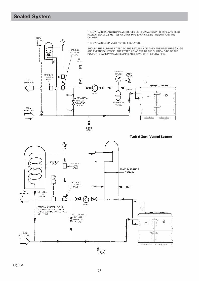
SEE FIG. 23
a. The installation must comply with the requirements of
BS6796 and BS 5449. Maximum water 82°C
temperature.
b. A safety valve set to operate at 2 bar (30Ibf/In2) shall
be fitted in the flow pipe close to the boiler. There must
not be any valve between the safety valve and the
boiler. The valve should be positioned on a discharge
pipe fitted to prevent and discharge or creating a
hazard to occupants or cause damage to electrical
components and wiring.
c. A pressure gauge covering at least the range 0 to 4
bar (0 to 60 Ibf/In2) shall be fitted in the system, in a
visible position.
d. A diaphragm type expansion vessel, to BS 4814 shall
be connected at a point in the return pipe close to the
boiler. The vessel must be chosen to suit the volume
of water in the cistern and the system charge must not
be less than the static head at the point of connection.
Further details can be obtained from the ‘British Gas
Specifications for Domestic Wet Central Heating
Systems Part 3 Sealed Systems’.
Vs = System Volume Litres
e. The hot water cylinder shall be either the indirect coil
type or a cylinder fitted with a calorifer which is
suitable for the system pressure.
f. The Make-Up System
Provision shall be made for replacing the lost hot water
from the system by either of the following methods:
a) From a make-up vessel or tank, and connected
through a non-return valve to the system on the
return side of the hot water cylinder or return side of
all heat emitters or radiators.
g. Mains Connection
There shall be no connection to mains water supply or
to the water storage cistern supplying domestic hot
water, even though a non-return valve may be fitted,
without the approval of the local water authority.
h. The Filling Point
The system shall be fitted with a filling point at a low
level, and be used in accordance with the local water
authority requirement, and shall generally have a stop
valve to BS 1010.
i. Commissioning - General
The system shall be filled by water by a method
acceptable to the Local Water Authority.
Check the operation of the safety valve manually.
Test the operation of the high limit cut-out according to
the manufacturers instructions.
After flushing and refilling the system either:-
a) If a make-up vessel is filled release water from the
safety valve until the level in the make-up vessel
bottle falls visibly, then top up the make-up bottle.
b) If there is no make-up vessel either release or
introduce water until the desired cold water
pressure level is reached.
Follow the commissioning instructions as for open vented
system. See section Commissioning Instructions with the
following additions:-
Fill the system until the pressure gauge registers 1.5 bar
(22 Ibf/In2). Clear any airlocks and check for water
soundness.
Check the operation of the safety valve, by allowing the
water pressure to rise until the valve opens. The valve
should open with ±0.3 bar (±4.35 Ibf/In2) of the pre-set
pressure. If this is not possible conduct a manual check
and test.
Release cold water for initial filling pressure.
Any set pointer gauge should be set to coincide with the
recommended filling pressure.
Sealed System
SEALED SYSTEM REQUIREMENTS
26
COMMISSIONING
Safety Valve Setting 2.0 bar
Vessel charge and
initial system pressure0.5 bar 1.0 bar
0.16
L
Vs
x
0.16
0.09
L
Vs
x
0.09
Multiplying Factor
Expansion Vessel
volume (litres)
= System volume Vs x
factor
27
Sealed System
Fig. 23
THE BY-PASS BALANCING VALVE SHOULD BE OF AN AUTOMATIC TYPE AND MUST
HAVE AT LEAST 2.5 METRES OF 28mm PIPE EACH SIDE BETWEEN IT AND THE
COOKER.
THE BY-PASS LOOP MUST NOT BE INSULATED.
SHOULD THE PUMP BE FITTED TO THE RETURN SIDE, THEN THE PRESSURE GAUGE
AND EXPANSION VESSEL ARE FITTED ADJACENT TO THE SUCTION SIDE OF THE
PUMP. THE SAFETY VALVE REMAINS AS SHOWN ON THE FLOW PIPE.
28
When in condensing mode the Stanley Brandon 80OCD
C/F boiler produces condensate from the water vapour in
the flue gases. Provision must be made for the safe and
effective removal of the condensate.
Condensate can be disposed either internally - into an
internal domestic waste system or directly into the soil
stack, or externally - to an external soil stack, gully,
hopper or soakaway.
It should be noted that connection of a condensate pipe to
the drain may be subject to local Building Control
requirements.
Pipework
Condensate disposal pipework must be plastic
(plastic waste pipe is suitable). Copper or steel pipe is
NOT suitable and should NOT be used.
The internal diameter of condensate disposal pipes
should not be less than 19mm - e.g. 22mm plastic
plumbing pipe or 19mm 3/4” plastic overflow pipe.
Condensate disposal pipes must be fitted with a fall
of 2.5° (1:20).
For boilers installed where it is not possible for the pipe to
fall towards the point of discharge - either internally into a
waste system or externally to a gulley - e.g. in a
basement, it will be necessary to use a condensate pump.
Condensate disposal pipes should be kept as short as
possible and the number of bends kept to a minimum.
Pipes should be adequately fixed to prevent sagging, i.e.
at no more than 0.5 metre intervals.
Ideally, external pipework, or pipework in unheated areas
such as garages, should be avoided. If unavoidable,
external pipework should be kept as short as possible
(less than 3 metres) and 32mm waste pipe used to
minimise the risk of freezing.
The number of bends, fittings and joints on external pipes
should be kept to a minimum to reduce the risk of trapping
condensate.
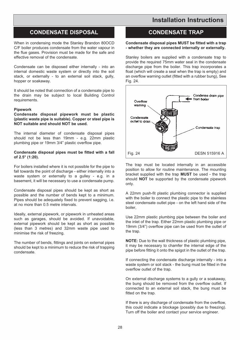
Condensate disposal pipes MUST be fitted with a trap
- whether they are connected internally or externally.
Stanley boilers are supplied with a condensate trap to
provide the required 75mm water seal in the condensate
discharge pipe from the boiler. This trap incorporates a
float (which will create a seal when the trap is empty) and
an overflow warning outlet (fitted with a rubber bung), See
Fig. 24.
The trap must be located internally in an accessible
position to allow for routine maintenance. The mounting
bracket supplied with the trap MUST be used - the trap
should NOT be supported by the condensate pipework
only.
A 22mm push-fit plastic plumbing connector is supplied
with the boiler to connect the plastic pipe to the stainless
steel condensate outlet pipe - on the left hand side of the
boiler,
Use 22mm plastic plumbing pipe between the boiler and
the inlet of the trap. Either 22mm plastic plumbing pipe or
19mm (3/4”) overflow pipe can be used from the outlet of
the trap.
NOTE: Due to the wall thickness of plastic plumbing pipe,
it may be necessary to chamfer the internal edge of the
pipe before fitting it onto the spigot in the outlet of the trap.
If connecting the condensate discharge internally - into a
waste system or soil stack - the bung must be fitted in the
overflow outlet of the trap.
On external discharge systems to a gully or a soakaway,
the bung should be removed from the overflow outlet. If
connected to an external soil stack, the bung must be
fitted on the trap.
If there is any discharge of condensate from the overflow,
this could indicate a blockage (possibly due to freezing).
Turn off the boiler and contact your service engineer.
Installation Instructions
CONDENSATE DISPOSAL CONDENSATE TRAP
Fig. 24 DESN 515916 A
29
Installation Instructions
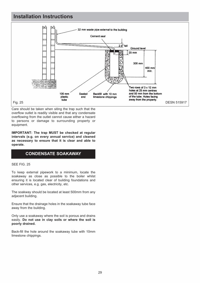
Fig. 25 DESN 515917
Care should be taken when siting the trap such that the
overflow outlet is readily visible and that any condensate
overflowing from the outlet cannot cause either a hazard
to persons or damage to surrounding property or
equipment.
IMPORTANT: The trap MUST be checked at regular
intervals (e.g. on every annual service) and cleaned
as necessary to ensure that it is clear and able to
operate.
SEE FIG. 25
To keep external pipework to a minimum, locate the
soakaway as close as possible to the boiler whilst
ensuring it is located clear of building foundations and
other services, e.g. gas, electricity, etc.
The soakway should be located at least 500mm from any
adjacent building.
Ensure that the drainage holes in the soakaway tube face
away from the building.
Only use a soakaway where the soil is porous and drains
easily. Do not use in clay soils or where the soil is
poorly drained.
Back-fill the hole around the soakaway tube with 10mm
limestone chippings.
CONDENSATE SOAKAWAY
30
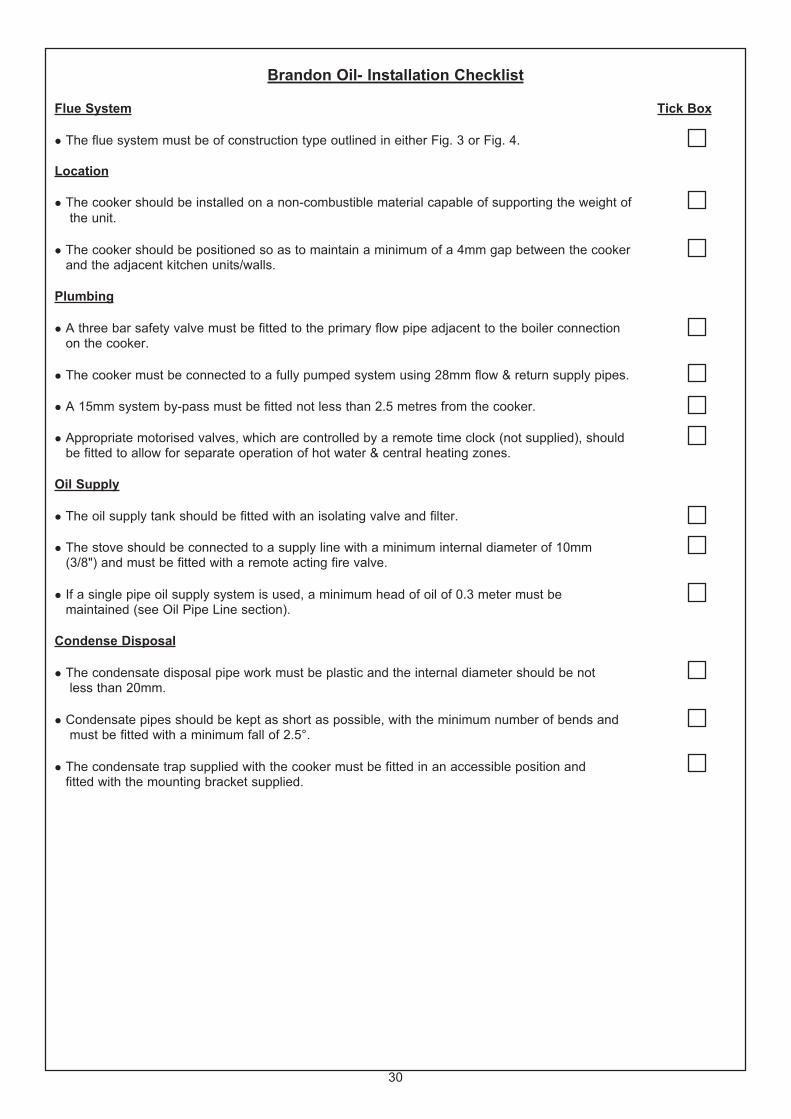
Brandon Oil- Installation Checklist
Flue System Tick Box
l The flue system must be of construction type outlined in either Fig. 3 or Fig. 4.
Location
l The cooker should be installed on a non-combustible material capable of supporting the weight of
the unit.
l The cooker should be positioned so as to maintain a minimum of a 4mm gap between the cookerand the adjacent kitchen units/walls.
Plumbing
l A three bar safety valve must be fitted to the primary flow pipe adjacent to the boiler connectionon the cooker.
l The cooker must be connected to a fully pumped system using 28mm flow & return supply pipes.
l A 15mm system by-pass must be fitted not less than 2.5 metres from the cooker.
l Appropriate motorised valves, which are controlled by a remote time clock (not supplied), shouldbe fitted to allow for separate operation of hot water & central heating zones.
Oil Supply
l The oil supply tank should be fitted with an isolating valve and filter.
l The stove should be connected to a supply line with a minimum internal diameter of 10mm (3/8") and must be fitted with a remote acting fire valve.
l If a single pipe oil supply system is used, a minimum head of oil of 0.3 meter must bemaintained (see Oil Pipe Line section).
Condense Disposal
l The condensate disposal pipe work must be plastic and the internal diameter should be notless than 20mm.
l Condensate pipes should be kept as short as possible, with the minimum number of bends andmust be fitted with a minimum fall of 2.5°.
l The condensate trap supplied with the cooker must be fitted in an accessible position andfitted with the mounting bracket supplied.

31
32
For further advice or information contact your
local distributor/stockist
With Waterford Stanley’s policy of continuous
product improvement, the Company reserves the
right to change specifications and make
modifications to the appliance described at any
time.
Supplied by
Waterford Stanley Ltd
Units 401 - 403
IDA Industrial Estate
Cork Road
Waterford
Ireland
Tel: (051) 302300 Fax: (051) 30-2315
www.waterfordstanley.com
Recommended