AC 2009-1301: BRIDGE DESIGN PROJECT: A HANDS-ON APPROACH TOSTATICS AND STRENGTH OF MATERIALS LEARNING
Guanghsu Chang, Minnesota State University, MankatoDr. Guanghsu A. Chang is an associate professor of the Automotive and ManufacturingEngineering Technology Department at Minnesota State University, Mankato. His researchinterests involve the study of robotic applications, manufacturing automation, Design forAssembly (DFA), and Case-Based Reasoning (CBR) applications. He holds both MSIE, andPh.D. degrees from University of Texas at Arlington.
William Peterson, Minnesota State University, MankatoDr. Bill Peterson is currently an associate professor and chair of the Automotive andManufacturing Engineering Technology Department at Minnesota State University, Mankato. Heholds a BIE from Auburn University. He spent twenty years in industry prior during which timehe earned an MBA and managed engineering, manufacturing, and plants in a wide variety ofindustries. He has spent the last 16 teaching industrial and manufacturing engineering,engineering management, and the management of technology. He is current program chair of theIE Division of ASEE and a director in two other divisions. He is past president of SEMS andASEM.
© American Society for Engineering Education, 2009
Page 14.289.1
Page 1 of 8
Bridge Design Project: A Hands-On Approach to
Statics and Strength of Materials Learning
Abstract
An obstacle for Manufacturing Engineering Technology (MET) students who are trying to learn Statics and Strength of Materials is their lack of involvement in their learning process. These students sit passively as instructors demonstrate concepts or, when solving the problems, are not active learners. In order to avoid this behavior, a bridge design project offers an interactive approach to engage students in the learning process. This paper provides some of the guidelines of a bridge design project that can be useful in active learning. Several project management skills are also integrated throughout the project. This paper describes our experience in developing the bridge design project. Introduction
Research has shown that project-based learning is an exceptionally effective learning activity. Many university professors today accept this learning environment to transform passive learning into active learning in their classrooms [1]. In order to find better ways of involving students in their learning process, we introduced the Bridge Design Project into our MET 322 Statics, Dynamics, and Mechanics of Materials course. With this bridge design project, students learn more material, retain the information longer, and enjoy the class activities more. The bridge design project allows students to explore many statics topics in the classroom with the help of the instructor and other classmates, rather than on their own. The bridge design project is one of active learning techniques used in this course to encourage students do more than simply listen to a lecture. They are building a bridge to prove their ideas and to demonstrate what they have learned from the course. After researching, processing, and applying information from websites, simulation software, and field trips, students are ready to share their ideas with team members. After dividing the students into teams (5 students/per team) and assign each a different role, they must work to design, construct, and test their team’s bridge. In order to make the bridge design project realistic, students have to practice project management skills and learn how to allocate and control the following resources: (1) $25,000 budget (2) construction time – 4 hours, and (3) building materials – straws, hot glues... etc.
Overview of Statics, and Strength of Materials Course
Many Manufacturing Engineering Technology (MET) curricula include both statics and strength of materials courses. These courses typically focus on different force systems and analysis of structures, which often involve a lot of formulas and theoretical concepts. The bridge design project attempts to provide student opportunities to practice their statics and strength of materials knowledge by designing, building, and testing a bridge based on the course concepts. At present, about 80 students at Minnesota State University (MSU), Mankato are involved with the project every year. All of the students are given a good foundational of concepts, principles and
Page 14.289.2
Page 2 of 8
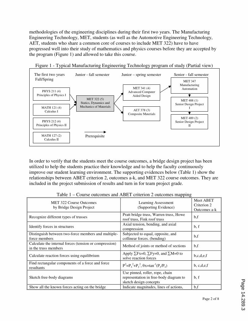
methodologies of the engineering disciplines during their first two years. The Manufacturing Engineering Technology, MET, students (as well as the Automotive Engineering Technology, AET, students who share a common core of courses to include MET 322) have to have progressed well into their study of mathematics and physics courses before they are accepted by the program (Figure 1) and allowed to take this course.
Figure 1 - Typical Manufacturing Engineering Technology program of study (Partial view)
In order to verify that the students meet the course outcomes, a bridge design project has been utilized to help the students practice their knowledge and to help the faculty continuously improve our student learning environment. The supporting evidences below (Table 1) show the relationships between ABET criterion 2, outcomes a-k, and MET 322 course outcomes. They are included in the project submission of results and turn in for team project grade.
Table 1 – Course outcomes and ABET criterion 2 outcomes mapping
MET 322 Course Outcomes by Bridge Design Project
Learning Assessment (Supporting Evidence)
Meet ABET Criterion 2 Outcomes a-k
Recognize different types of trusses Pratt bridge truss, Warren truss, Howe roof truss, Fink roof truss
b,f
Identify forces in structures Axial tension, bending, and axial compression
b, f
Distinguish between two-force members and multiple-force members
Subjected to equal, opposite, and collinear forces. (bending)
b,f
Calculate the internal forces (tension or compression) in the truss members
Method of joints or method of sections b,f
Calculate reaction forces using equilibrium Apply ∑Fx=0, ∑Fy=0, and ∑M=0 to solve reaction forces
b,c,d,e,f
Find rectangular components of a force and force resultants
P2=Px2+Py
2, σx=tan-1(Py/Px) b, c,d,e,f
Sketch free-body diagrams Use pinned, roller, rope, chain representation in free-body diagram to sketch design concepts
b, f
Show all the known forces acting on the bridge Indicate magnitudes, lines of actions, b,f
Prerequisite
Senior - fall semester
MET 322 (5) Statics, Dynamics and
Mechanics of Materials
PHYS 211 (4) Principles of Physics I
MATH 121 (4) Calculus I
MET 341 (4) Advanced Computer
Aided Design
AET 378 (3) Composite Materials
MET 347 Manufacturing
Automation
MET 488 (1) Senior Design Project
I
MET 489 (2) Senior Design Project
II
Junior - fall semester Junior – spring semester The first two years Fall/Spring
PHYS 212 (4) Principles of Physics II
MATH 127 (2) Calculus II
Page 14.289.3
Page 3 of 8
and senses.
Indicate all desired unknown forces and include as much known information as possible
Identify points of application, directions, senses, components.
b, f
Apply equilibrium equations to solve concurrent force systems
Apply ∑Fx=0, and ∑Fy=0 to solve unknown member forces for each joint.
b,c,d,e, f
Calculate resultants of parallel force systems and/or nonconcurrent force systems
Use R=∑Fy=F1+F2+F3+… to determine resultant of parallel force systems.
b, c,d,e,f
Identify different types of force systems Coplanar, concurrent, parallel .. b,f
Become familiar with conversion factors: U.S. customary to SI units
Force: pounds vs. Newtons Length: feet vs., millimeters
b, f
Review the Mathematics of Statics Knowledge of basic arithmetic, algebra, geometry, trigonometry,
b, f
Understand principles of stress and strain and their relationship
Tension test, Stress-strain diagram, proportional limit, rupture strength.
b, f
Note: ABET Criterion 2 Program Outcomes – Students will have: a. an appropriate mastery of the knowledge, techniques, skills and modern tools of their disciplines; b. an ability to apply current knowledge and adapt to emerging applications of mathematics, science, engineering and technology; c. an ability to conduct, analyze and interpret experiments and apply experimental results to improve processes; d. an ability to apply creativity in the design of systems, components or appropriate to program objectives; e. an ability to function effectively on teams; f. an ability to identify, analyze, and solve technical problems; g. an ability to communicate effectively; h. a recognition of the need for, and an ability to engage in lifelong learning; i. an ability to understand professional, ethical and social responsibility; j. a respect for diversity and knowledge of contemporary professional, societal and global issues; and k. a commitment to quality, timeliness, and continuous improvement.
The statics and strength of materials course is both a foundation and a framework for most of the following advanced MET courses. Many of the advanced courses have a prerequisite of statics and strength of materials. Thus, this statics and strength of materials course is critical to the MET curriculum. Not only is this course needed for student graduation, but it also serves to solidify the student’s understanding of other important subjects, including applied mathematics, physics, and graphics. The bridge design project emphasizes cross-discipline interaction (since the teams include both MET and AET majors), active learning, and sustainable development in a professional framework in support of goals set forth by MET program. With about 99% student participation in the bridge design project, the motivation among the students is high and considerable enthusiasm and interaction is seen among the students. Finally, the students are able to successfully plan, design, and construct a bridge project on a small budget within a relatively short time frame.
Bridge Design Project
When MET 322 students finished the first part of the five-times-a-week five-week statics lectures, they use this knowledge to build a bridge. The objective of the project is to help our students successfully apply their knowledge to create a successful bridge design. A successful design is one that satisfies all the design specifications, meets project budget, and cuts down construction time requirements. To meet the objective, project team includes the following positions (5 students/per team):
(1) Project manager – organize meetings and making decisions
Page 14.289.4
Page 4 of 8
(2) Design engineer – develop a bridge design concept and conduct detailed designs (3) Procurement engineer – make a materials requirement plan and Bill of Materials (BOM) (4) Manufacturing engineer(s) – follow design drawing and build the bridge (5) Accountant – control budget and time
This project can be divided into four different phases:
(1) Research and conceptual design phase, (1-2 hours) Task 1: conduct research on the internet and explore information about bridges Task 2: define your design concept in 50 words (free hand drawing)
(2) Structural design and materials procurement phase, (1 hour) Task 3: sketch your bridge design (output – bridge drawing on graph paper, scale 1:1) Task 4: prepare a Bill of Materials (BOM) for materials procurement
(3) Construction phase, (2 hours) Task 5: build your bridge in the classroom
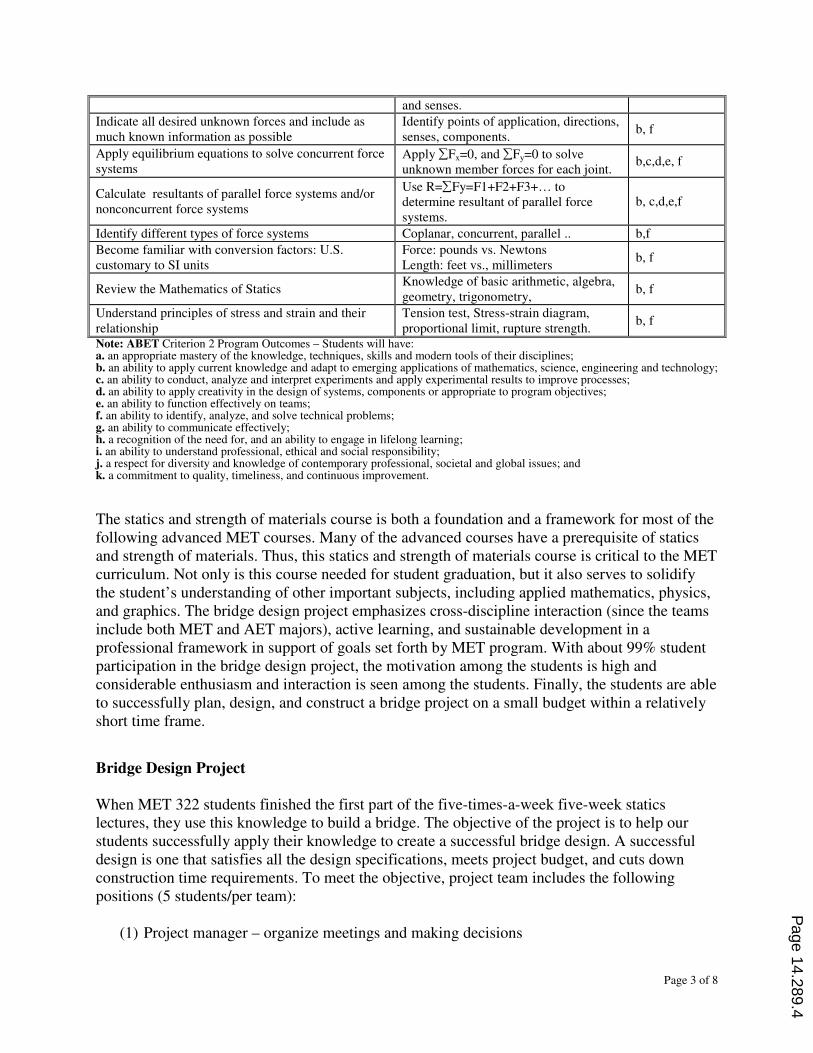
(4) Bridge testing phase (1 hour) - Figure 2. Task 6: test and check bridge performance
Figure 2 – Bridge load testing and structural
monitoring
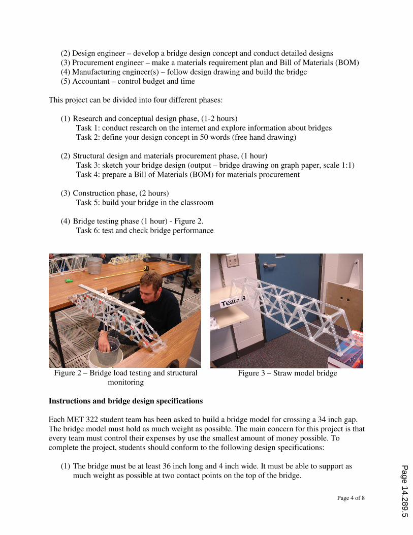
Figure 3 – Straw model bridge
Instructions and bridge design specifications
Each MET 322 student team has been asked to build a bridge model for crossing a 34 inch gap. The bridge model must hold as much weight as possible. The main concern for this project is that every team must control their expenses by use the smallest amount of money possible. To complete the project, students should conform to the following design specifications:
(1) The bridge must be at least 36 inch long and 4 inch wide. It must be able to support as much weight as possible at two contact points on the top of the bridge.
Page 14.289.5
Page 5 of 8
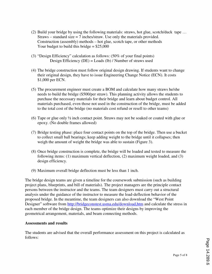
(2) Build your bridge by using the following materials: straws, hot glue, scotch/duck tape …
Straws – standard size = 7 inches/straw. Use only the materials provided. Construction (assembly) methods – hot glue, scotch tape, or other methods Your budget to build this bridge = $25,000
(3) “Design Efficiency” calculation as follows: (50% of your final points)
Design Efficiency (DE) = Loads (lb) / Number of straws used (4) The bridge construction must follow original design drawing. If students want to change
their original design, they have to issue Engineering Change Notice (ECN). It costs $1,000 per ECN.
(5) The procurement engineer must create a BOM and calculate how many straws he/she
needs to build the bridge ($500/per straw). This planning activity allows the students to purchase the necessary materials for their bridge and learn about budget control. All materials purchased, even those not used in the construction of the bridge, must be added to the total cost of the bridge (no materials cost refund or resell to other teams)
(6) Tape or glue only ½ inch contact point. Straws may not be soaked or coated with glue or
epoxy. (No double frames allowed) (7) Bridge testing phase: place four contact points on the top of the bridge. Then use a bucket
to collect small ball bearings; keep adding weight to the bridge until it collapses; then weigh the amount of weight the bridge was able to sustain (Figure 3).
(8) Once bridge construction is complete, the bridge will be loaded and tested to measure the
following items: (1) maximum vertical deflection, (2) maximum weight loaded, and (3) design efficiency.
(9) Maximum overall bridge deflection must be less than 1 inch.
The bridge design teams are given a timeline for the coursework submission (such as building project plans, blueprints, and bill of materials). The project managers are the principle contact persons between the instructor and the teams. The team designers must carry out a structural analysis under the guidance of the instructor to measure the load-deflection behavior of the proposed bridge. In the meantime, the team designers can also download the “West Point Designer” software from http://bridgeconstest.usma.edu/download,htm and calculate the stress in each member of the bridge design. The teams optimize their designs by improving the geometrical arrangement, materials, and beam connecting methods. Assessments and results
The students are advised that the overall performance assessment on this project is calculated as follows:
Page 14.289.6
Page 6 of 8
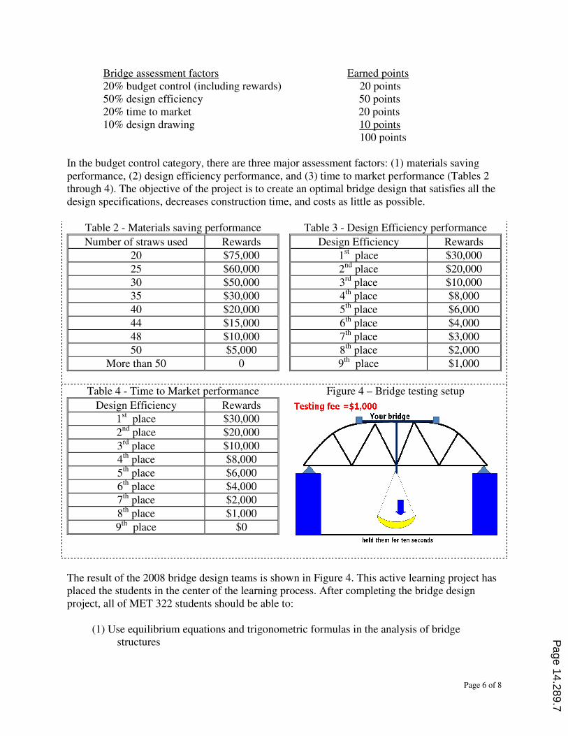
Bridge assessment factors Earned points 20% budget control (including rewards) 20 points 50% design efficiency 50 points 20% time to market 20 points 10% design drawing 10 points 100 points In the budget control category, there are three major assessment factors: (1) materials saving performance, (2) design efficiency performance, and (3) time to market performance (Tables 2 through 4). The objective of the project is to create an optimal bridge design that satisfies all the design specifications, decreases construction time, and costs as little as possible.
Table 2 - Materials saving performance
Number of straws used Rewards
20 $75,000
25 $60,000
30 $50,000
35 $30,000
40 $20,000
44 $15,000
48 $10,000
50 $5,000
More than 50 0
Table 3 - Design Efficiency performance
Design Efficiency Rewards
1st place $30,000
2nd place $20,000
3rd place $10,000
4th place $8,000
5th place $6,000
6th place $4,000
7th place $3,000
8th place $2,000
9th place $1,000
Table 4 - Time to Market performance
Design Efficiency Rewards
1st place $30,000
2nd place $20,000
3rd place $10,000
4th place $8,000
5th place $6,000
6th place $4,000
7th place $2,000
8th place $1,000
9th place $0
Figure 4 – Bridge testing setup
The result of the 2008 bridge design teams is shown in Figure 4. This active learning project has placed the students in the center of the learning process. After completing the bridge design project, all of MET 322 students should be able to:
(1) Use equilibrium equations and trigonometric formulas in the analysis of bridge structures
Page 14.289.7
Page 7 of 8
(2) Explain in the physical conditions required for equilibrium of a point and demonstrate how these conditions are described mathematically
(3) Determine the magnitude and location of the resultant for uniform distributed loads (4) Solve the equations of equilibrium for the bridge that is acted on by external loads (5) Calculate the pin reactions for two supporting ends of the bridge
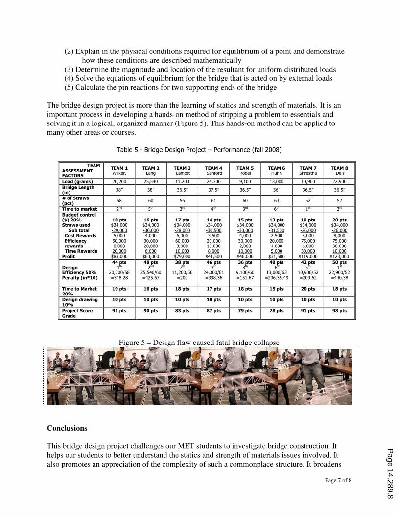
The bridge design project is more than the learning of statics and strength of materials. It is an important process in developing a hands-on method of stripping a problem to essentials and solving it in a logical, organized manner (Figure 5). This hands-on method can be applied to many other areas or courses.
Table 5 - Bridge Design Project – Performance (fall 2008)
TEAM ASSESSMENT FACTORS
TEAM 1 Wilker,
TEAM 2 Lang
TEAM 3 Lamott
TEAM 4 Sanford
TEAM 5 Rodel
TEAM 6 Huhn
TEAM 7 Shrestha
TEAM 8 Deis
Load (grams) 20,200 25,540 11,200 24,300 9,100 13,000 10,900 22,900
Bridge Length (in)
38” 38” 36.5” 37.5” 36.5” 36” 36,5” 36.5”
# of Straws (pcs)
58 60 56 61 60 63 52 52
Time to market 2nd 5th 3rd 4th 3rd 6th 1st 3rd
Budget control ($) 20% Straws used Sub total Cost Rewards Efficiency rewards Time Rewards Profit
18 pts $34,000 -29,000 5,000 50,000 8,000 20,000 $83,000
16 pts $34,000 -30,000 4,000 30,000 20,000 6,000
$60,000
17 pts $34,000 -28,000 6,000 60,000 3,000 10,000 $79,000
14 pts $34,000 -30,500 3,500 20,000 10,000 8,000
$41,500
15 pts $34,000 -30,000 4,000 30,000 2,000 10,000 $46,000
13 pts $34,000 -31,500 2,500 20,000 4,000 5,000
$31,500
19 pts $34,000 -26,000 8,000 75,000 6,000 30,000
$119,000
20 pts $34,000 -26,000 8,000 75,000 30,000 10,000
$123,000
Design Efficiency 50% Penalty (in*10)
44 pts 4th
20,200/58 =348.28
48 pts 2nd
25,540/60 =425.67
38 pts 7th
11,200/56 =200
46 pts 3rd
24,300/61 =398.36
36 pts 8th
9,100/60 =151.67
40 pts 6th
13,000/63 =206.35.49
42 pts 5th
10,900/52 =209.62
50 pts 1st
22,900/52 =440.38
Time to Market 20%
19 pts 16 pts 18 pts 17 pts 18 pts 15 pts 20 pts 18 pts
Design drawing 10%
10 pts 10 pts 10 pts 10 pts 10 pts 10 pts 10 pts 10 pts
Project Score Grade
91 pts 90 pts 83 pts 87 pts 79 pts 78 pts 91 pts 98 pts
Figure 5 – Design flaw caused fatal bridge collapse
Conclusions
This bridge design project challenges our MET students to investigate bridge construction. It helps our students to better understand the statics and strength of materials issues involved. It also promotes an appreciation of the complexity of such a commonplace structure. It broadens
Page 14.289.8
Page 8 of 8
the students’ knowledge of the career opportunities that is present in building bridges. It allows our students to strengthen their technology skills, exercise their creativity, and also practice their research skills. They will research materials and methods being used. Finally, our students will demonstrate their new knowledge and insight by designing their own bridge and then testing it for strength and the integrity of structure. When they finish, they will be better informed about a structure that they have probably taken for granted. They will understand how this might be helpful to them in their lifetime. This bridge design project is a motivational, fun, and enlightening project that provides students a hands-on opportunity while combining and practicing math, science, and project management skills.
References
1. University of California Davis, Teaching Resources Center. http://trc.ucdavis.edu/ 2. Chang, Guanghsu A. “Building a bridge” PowerPoint lecture materials, Manufacturing
Engineering Technology Department, Minnesota State University, Mankato 2009 3. Limbrunner, Georage F. and Leonard Spiegel “Applied Statics and Strength of Materials” fifth
edition, Prentice Hall, upper saddle river, New Jersey, 2009 4. O’Kelly Brendan C. “Case study of a problem-based bridge engineering design course”
International Symposium for Engineering Education, 2007, Dublin City University, Ireland. 5. Leitch, Kenneth R. “Building a bridge: A case in project service learning” American Society
for Engineering Education, Indiana and North Central Joint Section Conference, March 31-April 1, 2006
Page 14.289.9
Recommended