Confidential
FACSIMILE EQUIPMENT SERVICE MANUAL MODELS: FAX2820/2920
MFC7220/7225N
i Confidential
PREFACE This Service Manual is intended for use by service personnel and details the specifications, construction, theory of operation, and maintenance for the Brother machines noted on the front cover. It includes information required for troubleshooting and service--disassembly, reassembly, and lubrication--so that service personnel will be able to understand equipment function, repair the equipment in a timely manner and order spare parts as necessary. To perform appropriate maintenance so that the machine is always in the best possible condition for the customer, service personnel must adequately understand and apply this manual.
HOW THIS MANUAL IS ORGANIZED This manual is made up of nine chapters and appendices.
CHAPTER 1 PARTS NAMES AND FUNCTIONS Contains external views and names of components and describes their functions. Information about the keys on the control panel is included to help you check operation or make adjustments.
CHAPTER 2 SPECIFICATIONS Lists the specifications of each model, which enables you to make a comparison of different models.
CHAPTER 3 THEORY OF OPERATION Gives an overview of the scanning and printing mechanisms as well as the sensors, actuators, and control electronics. It aids in understanding the basic principles of operation as well as locating defects for troubleshooting.
CHAPTER 4 TRANSFER OF DATA LEFT IN THE MACHINE TO BE SENT FOR REPAIR Describes how to transfer data left in the machine to be sent for repair. The service personnel should instruct end users to follow the transfer procedure given in this chapter if the machine at the user site cannot print received data due to the printing mechanism defective. End users can transfer received data to another machine to prevent data loss.
CHAPTER 5 DISASSEMBLY/REASSEMBLY AND LUBRICATION Details procedures for disassembling and reassembling the machine together with related notes. The disassembly order flow provided enables you to see at a glance the quickest way to get to component(s) involved. At the start of a disassembly job, you check a disassembly order flow that guides you through a shortcut to the object components. This chapter also covers screw tightening torques and lubrication points to which the specified lubricants should be applied during reassembly jobs.
CHAPTER 6 ADJUSTMENTS AND UPDATING OF SETTINGS REQUIRED AFTER PARTS REPLACEMENT
Details adjustments and updating of settings, which are required if the main PCB and some other parts have been replaced. CHAPTER 7 CLEANING Provides cleaning procedures not covered by the User's Manual. Before starting any repair work, clean the machine as it may solve the problem concerned.
ii Confidential
CHAPTER 8 MAINTENANCE MODE Describes the maintenance mode which is exclusively designed for the purpose of checks, settings and adjustments using the keys on the control panel. In the maintenance mode, you can update memory (EEPROM: electrically erasable programmable read-only memory) for setting the CIS scanner area, for example. You can also customize the EEPROM according to the shipment destination of the machine concerned. In addition, you can perform operational checks of the LCD, control panel PCB or sensors, perform a print test, display the log information or error codes, and modify firmware switches (WSW).
CHAPTER 9 ERROR INDICATION AND TROUBLESHOOTING Details error messages and codes that the incorporated self-diagnostic functions display if any error or malfunction occurs. If any error message appears, refer to this chapter to find which components should be checked or replaced. The latter half of this chapter provides sample problems that could occur in the main sections of the machine and related troubleshooting procedures. This will help service personnel pinpoint and repair defective components. APPENDIX 1 SERIAL NUMBERING SYSTEM Shows the location of serial number labels put on some parts and lists the coding information pertaining to the serial numbers.
APPENDIX 2 FIRMWARE INSTALLATION Provides instructions on how to update firmware stored in the flash ROM on the main PCB or load firmware to a new main PCB from the host PC. No hardware replacement is required for updating.
APPENDIX 3 CUSTOMIZING CODES ACCORDING TO SHIPPING DESTINATION Lists the customizing codes for the various preferences exclusively designed for each destination (e.g. language). Those codes are stored in the memory (EEPROM) mounted on the main PCB. If the main PCB is replaced with a new one, therefore, you will need to set the proper customizing codes with the machine in the maintenance mode.
APPENDIX 4 FIRMWARE SWITCHES (WSW) Describes the functions of the firmware switches, which can be divided into two groups: one is for customizing preferences designed for the shipping destination (as described in Appendix 3) and the other is for modifying preferences that match the machine to the environmental conditions. Use the latter group if the machine malfunctions due to mismatching.
APPENDIX 5 WIRING DIAGRAM Provides the wiring diagram that helps you understand the connections between PCBs.
APPENDIX 6 CIRCUIT DIAGRAMS Provides the circuit diagrams of the NCU PCB and power supply PCB.
This manual describes the models and their versions destined for major countries. The specifications and functions are subject to change depending upon each destination.
manuals4you.commanuals4you.com
iii Confidential
TABLE OF CONTENTS CHAPTER 1 PARTS NAMES & FUNCTIONS
1.1 EQUIPMENT OUTLINE.............................................................................................1-1
1.2 CONTROL PANEL ....................................................................................................1-2
1.3 COMPONENTS .........................................................................................................1-5
CHAPTER 2 SPECIFICATIONS
2.1 GENGERAL...............................................................................................................2-1
2.1.1 General Specifications .........................................................................................2-1
2.1.2 Paper Specifications.............................................................................................2-2
2.1.3 Printable Area ................................................................................................................2-4
2.2 SPECIFICATIONS LIST ............................................................................................2-8
CHAPTER 3 THEORY OF OPERATION
3.1 Overview ...................................................................................................................3-1
3.2 Mechanical Components.........................................................................................3-2
3.2.1 Scanner Mechanism ............................................................................................3-3
3.2.2 Document Feeding and Ejecting Mechanism.......................................................3-3
3.2.3 Scanner ................................................................................................................3-3
3.2.4 Printing Mechanism..............................................................................................3-4
3.2.4.1 Paper supply ................................................................................................3-4
3.2.4.2 Push-up function of paper tray.....................................................................3-6
3.2.4.3 Paper registration.........................................................................................3-8
3.2.4.4 Paper eject ...................................................................................................3-9
3.2.4.5 Drum unit......................................................................................................3-9
3.2.4.6 Toner cartridge...........................................................................................3-10
3.2.4.7 Print process ..............................................................................................3-13
3.2.5 Sensors and Actuators .......................................................................................3-16
3.3 Control Electronics................................................................................................3-17
3.3.1 Components .......................................................................................................3-17
CHAPTER 4 TRANSFER OF DATA LEFT IN THE MACHINE TO BE SENT FOR REPAIR
4.1 TRANSFERRING RECEIVED FAX DATA ................................................................4-1
iv Confidential
CHAPTER 5 DISASSEMBLY/REASSEMBLY AND LUBRICATION
5.1 DISASSEMBLY/REASSEMBLY ...............................................................................5-1
Safety Precautions........................................................................................................5-1
Tightening Torque.........................................................................................................5-2
Preparation ...................................................................................................................5-3
How to Access the Object Component .........................................................................5-3
Disassembly Flowchart .................................................................................................5-4
5.1.1 Paper Eject Tray...................................................................................................5-5
5.1.2 Drum/Toner ASSY................................................................................................5-5
5.1.3 Paper Tray............................................................................................................5-6
5.1.4 Back Cover...........................................................................................................5-7
5.1.5 Rear Chute Cover ................................................................................................5-8
5.1.6 Document Base ASSY .........................................................................................5-9
5.1.7 Side Cover L.......................................................................................................5-10
5.1.8 Handset Holder ..................................................................................................5-11
5.1.9 Speaker ASSY ...................................................................................................5-12
5.1.10 Side Cover R/Link Stopper.................................................................................5-13
5.1.11 Panel Unit ...........................................................................................................5-14
5.1.12 Hook PCB ASSY................................................................................................5-20
5.1.13 Top Cover...........................................................................................................5-21
5.1.14 NCU PCB ASSY.................................................................................................5-32
5.1.15 Paper Stopper L/S..............................................................................................5-34
5.1.16 Front Cover ........................................................................................................5-35
5.1.17 Pickup Roller Holder ASSY................................................................................5-36
5.1.18 Fixing Unit ..........................................................................................................5-40
5.1.19 High-Voltage PS PCB ASSY..............................................................................5-45
5.1.20 Main PCB ...........................................................................................................5-46
5.1.21 PS PCB Unit/Fan 40...........................................................................................5-48
5.1.22 Laser Unit ...........................................................................................................5-52
5.1.23 Sub Chute ASSY................................................................................................5-53
5.1.24 Link Lever...........................................................................................................5-54
manuals4you.commanuals4you.com
v Confidential
5.1.25 Tail Edge Actuator..............................................................................................5-55
5.1.26 Regist Front Actuator/Regist Front Spring .........................................................5-55
5.1.27 Regist Sensor PCB ASSY..................................................................................5-56
5.1.28 Regist Rear Actuator/Regist Rear Spring...........................................................5-56
5.1.29 Fan Motor 60 Unit...............................................................................................5-57
5.1.30 Toner LED PCB ASSY/LED Holder ...................................................................5-58
5.1.31 New Toner Actuator/New Toner Actuator Spring...............................................5-59
5.1.32 New Toner Sensor .............................................................................................5-59
5.1.33 Cover Sensor .....................................................................................................5-60
5.1.34 Toner Sensor PCB ASSY...................................................................................5-60
5.1.35 Main Motor ASSY...............................................................................................5-61
5.1.36 Develop Joint......................................................................................................5-62
5.1.37 P/R Solenoid ASSY............................................................................................5-63
5.1.38 F/R Solenoid ASSY ............................................................................................5-63
5.1.39 Main Frame L .....................................................................................................5-65
5.1.40 Main Frame R.....................................................................................................5-66
5.1.41 Harness Routing.................................................................................................5-67
5.2 LUBRICATION ........................................................................................................5-74
CHAPTER 6 ADJUSTMENTS AND UPDATING OF SETTINGS, REQUIRED AFTER PARTS
REPLACEMENT
6.1 IF YOU REPLACE THE MAIN PCB..........................................................................6-1
[ 1 ] Load update programs/data.........................................................................6-1
[ 2 ] Initialize the EEPROM on the main PCB (Function code 01) ......................6-1
[ 3 ] Customize the EEPROM on the main PCB (Function code 74) ..................6-1
[ 4 ] Check the control panel PCB for normal operation (Function code 13) ......6-1
[ 5 ] Adjust the handset volume (Function code 16)............................................6-1
[ 6 ] Make a sensor operation check (Function code 32)....................................6-1
[ 7 ] Adjust the scan start/end positions (Function code 54) ...............................6-1
[ 8 ] Acquire of white level data and set the CIS scanner area (Function code 55) .......................................................................................6-1
[ 9 ] Setting the serial number .............................................................................6-1
[ 10 ] Inputting the adjusted value of the laser scanner ........................................6-1
[ 11 ] Switch back to standby ................................................................................6-1
vi Confidential
6.2 IF YOU REPLACE THE CIS......................................................................................6-2
6.3 IF YOU REPLACE THE LASER UNIT ......................................................................6-2
CHAPTER 7 CLEANING CHAPTER 8 MAINTENANCE MODE
8.1 ENTRY INTO THE MAINTENANCE MODE .............................................................8-1
8.2 LIST OF MAINTENANCE MODE FUNCTIONS........................................................8-2
8.3 USER-ACCESS TO THE MAINTENANCE MODE ...................................................8-3
8.4 DETAILED DESCRIPTION OF MAINTENANCE MODE FUNCTIONS....................8-5
8.4.1 EEPROM Parameter Initialization (Function code 01/91) ....................................8-5
8.4.2 Printout of Scanning Compensation Data (Function code 05) .............................8-6
8.4.3 ADF Performance Test (Function mode 08) ........................................................8-8
8.4.4 Test Pattern (Function mode 09) .........................................................................8-9
8.4.5 Firmware Switch Setting and Printout ................................................................8-10
8.4.5.1 Firmware switch setting (Function mode 10) .............................................8-10
8.4.5.2 Printout of firmware switch data (Function mode 11).................................8-12
8.4.6 Operation Check of LCD (Function mode 12)....................................................8-13
8.4.7 Operational Check of Control Panel PCB (Function mode 13) ..........................8-14
8.4.8 Adjustment of Handset Volume (Function code 16) ..........................................8-15
8.4.9 Sensor Operational Check (Function mode 32).................................................8-16
8.4.10 Received Data Transfer Function (Function mode 53) ......................................8-17
8.4.11 Fine Adjustment of Scan Start/End Positions (Function mode 54) ....................8-19
8.4.12 Acquisition of White Level Data and CIS Scanner Area Setting (Function mode 55)............................................................................................8-21
8.4.13 Continuous print Test (Function mode 67).........................................................8-21
8.4.14 EEPROM Customizing (Function mode 74).......................................................8-22
8.4.15 Display of the Equipment’s Log Information (Function mode 80) ......................8-23
8.4.16 Machine Error Code Indication (Function mode 82) ..........................................8-25
8.4.17 Output of Transmission Log to the Telephone Line (Function mode 87)...........8-25
8.4.18 Cancellation of the Memory Security Mode........................................................8-25
manuals4you.commanuals4you.com
vii Confidential
CHAPTER 9 ERROR INDICATION AND TROUBLESHOOTING 9.1 error indication.........................................................................................................9-1
9.1.1 Equipment Errors .................................................................................................9-1
[ 1 ] Error messages appearing on the LCD .......................................................9-1
[ 2 ] Error codes shown in "MACHINE ERROR X X" messages.........................9-6
9.1.2 Communications Errors......................................................................................9-12
9.2 troubleshooting......................................................................................................9-16
9.2.1 Introduction.........................................................................................................9-16
9.2.2 Precautions ........................................................................................................9-16
9.2.3 Checking Prior to Troubleshooting.....................................................................9-16
9.2.4 Troubleshooting Based on Problem Type..........................................................9-17
[ 1 ] Paper feeding problems.............................................................................9-17
[ 2 ] Software setting problems .........................................................................9-19
[ 3 ] Malfunction.................................................................................................9-22
[ 4 ] Image defects ............................................................................................9-28
[ 5 ] Incorrect printout ........................................................................................9-49
[ 6 ] Network problem........................................................................................9-51
[ 7 ] Troubleshooting of the control panel..........................................................9-55
[ 8 ] Troubleshooting of fax functions ................................................................9-57
APPENDIX 1 SERIAL NUMBERING SYSTEM APPENDIX 2 FIRMWARE INSTALLATION
A2.1 INSTALLING THE UPDATE DATA TO THE MACHINE..................................App. 2-1
A2.2 SETTING ID CODES TO MACHINES..............................................................App. 2-8
APPENDIX 3 CUSTOMIZING CODES ACCORDING TO SHIPPING DESTINATION APPENDIX 4 FIRMWARE SWITCHES (WSW) APPENDIX 5 WIRING DIAGRAM APPENDIX 6 CIRCUIT DIAGRAMS NCU PCB (U.S.A. and CANADA models)
NCU PCB (EUROPE models)
Power Supply PCB 100V (U.S.A. and CANADA models)
Power Supply PCB 200V (EUROPE models)
Confidential viii
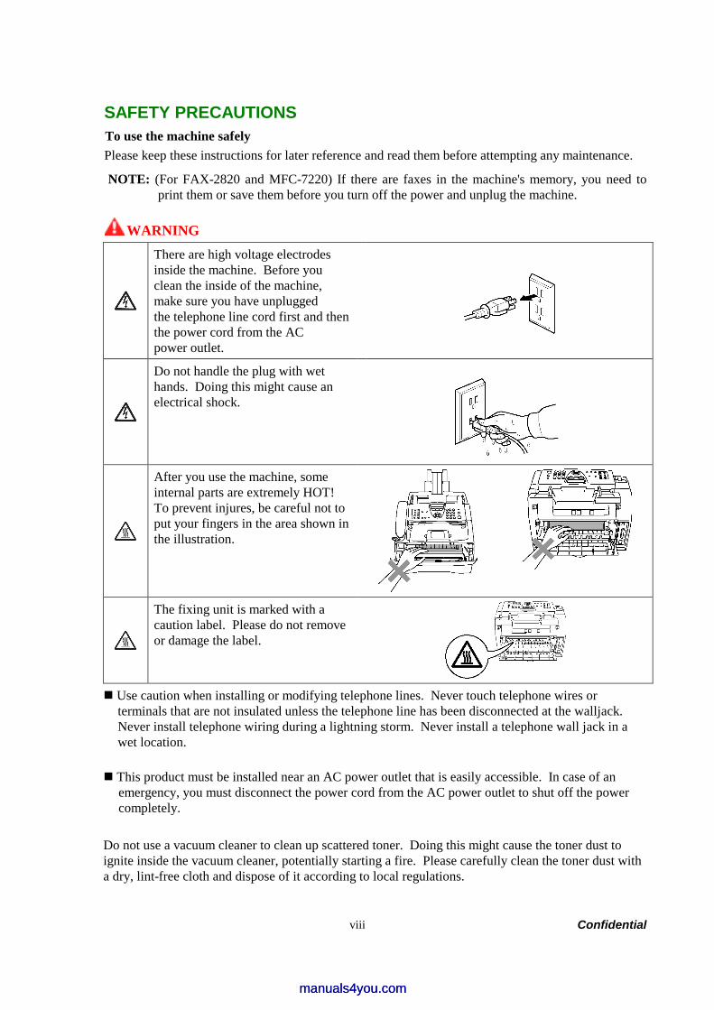
SAFETY PRECAUTIONS To use the machine safely Please keep these instructions for later reference and read them before attempting any maintenance.
NOTE: (For FAX-2820 and MFC-7220) If there are faxes in the machine's memory, you need to print them or save them before you turn off the power and unplug the machine.
WARNING
There are high voltage electrodes inside the machine. Before you clean the inside of the machine, make sure you have unplugged the telephone line cord first and then the power cord from the AC power outlet.
Do not handle the plug with wet hands. Doing this might cause an electrical shock.
After you use the machine, some internal parts are extremely HOT! To prevent injures, be careful not to put your fingers in the area shown inthe illustration.
The fixing unit is marked with a caution label. Please do not remove or damage the label.
Use caution when installing or modifying telephone lines. Never touch telephone wires or terminals that are not insulated unless the telephone line has been disconnected at the walljack. Never install telephone wiring during a lightning storm. Never install a telephone wall jack in a wet location.
This product must be installed near an AC power outlet that is easily accessible. In case of an emergency, you must disconnect the power cord from the AC power outlet to shut off the power completely.
Do not use a vacuum cleaner to clean up scattered toner. Doing this might cause the toner dust to ignite inside the vacuum cleaner, potentially starting a fire. Please carefully clean the toner dust with a dry, lint-free cloth and dispose of it according to local regulations.
manuals4you.commanuals4you.com
Confidential ix
WARNING IMPORTANT SAFETY INSTRUCTIONS When using your telephone equipment, basic safety precautions should always be followed to reduce the risk of fire, electric shock and injury to people, including the following: 1. Do not use this product near water, for example, near a bath tub, wash bowl, kitchen sink or
washing machine, in a wet basement or near a swimming pool. 2. Avoid using this product during an electrical storm. There may be a remote risk of electric
shock from lightning. 3. Do not use this product to report a gas leak in the vicinity of the leak. 4. Use only the power cord supplied with this machine. SAVE THESE INSTRUCTIONS

Confidential x
CHOOSING A LOCATION Place your machine on a flat, stable surface that is free of vibration and shocks, such as a desk. Put the machine near a telephone wall jack and a standard, grounded AC power outlet. Choose a location where the temperature remains between 50°F and 90.5°F (10°C and 32.5°C).
CAUTION • Avoid placing your machine in a high-traffic area. • Do not place the machine near heaters, air conditioners, water, chemicals, or refrigerators. • Do not expose the machine to direct sunlight, excessive heat, moisture, or dust. • Do not connect your machine to an AC power outlet controlled by wall switches or automatic
timers. • Disruption of power can wipe out information in the machine’s memory. • Do not connect your machine to an AC power outlet on the same circuit as large appliances or
other equipment that might disrupt the power supply. • Avoid interference sources, such as speakers or the base units of cordless phones.
manuals4you.commanuals4you.com

Confidential
CHAPTER 1PARTS NAMES & FUNCTIONS
Confidential
CHAPTER 1 PARTS NAMES & FUNCTIONS
This chapter contains external views and names of components and describes their functions. Information about the keys on the control panel is included to help you check operation or make adjustments.
CONTENTS
1.1 EQUIPMENT OUTLINE ...................................................................................................1-1
1.2 CONTROL PANEL...........................................................................................................1-2
1.3 COMPONENTS................................................................................................................1-5
manuals4you.commanuals4you.com
1-1 Confidential
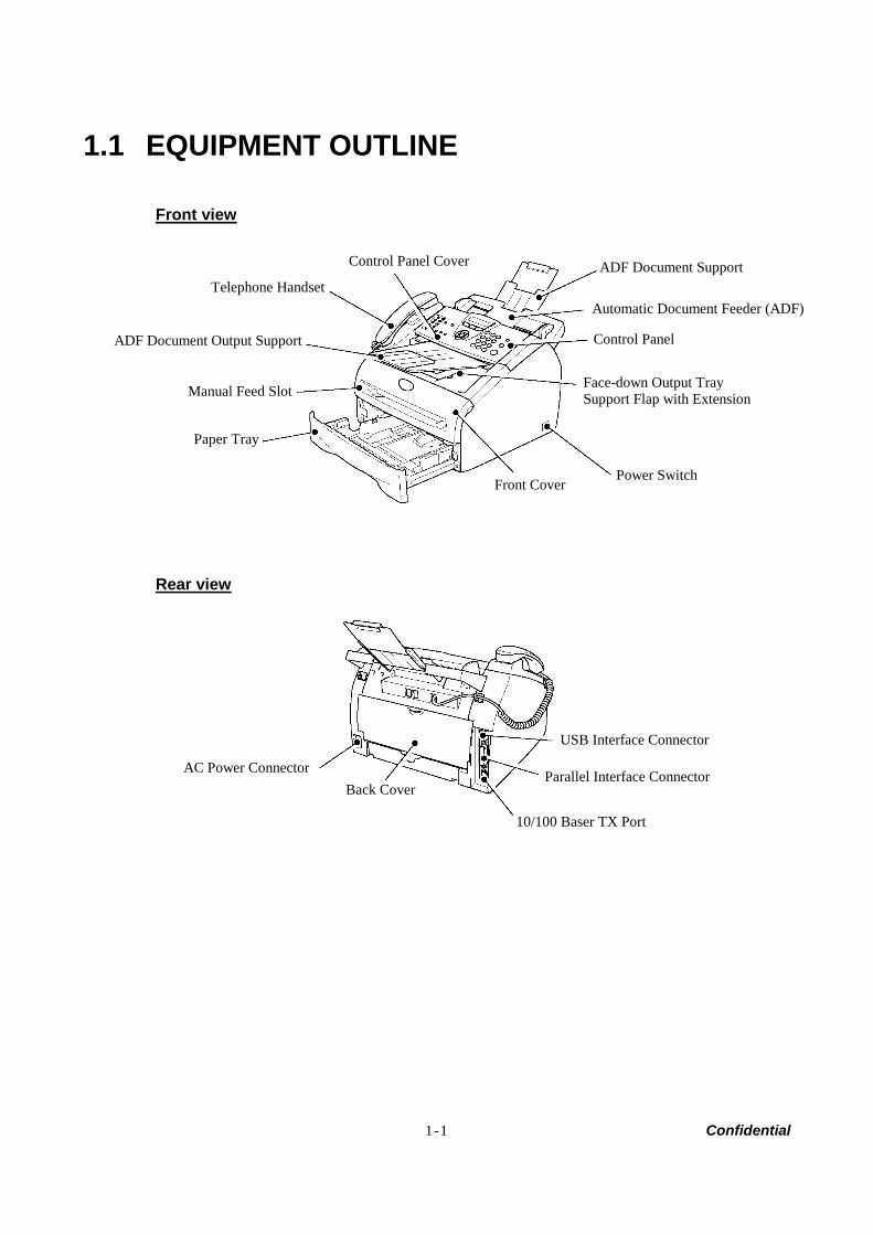
1.1 EQUIPMENT OUTLINE
Front view
Rear view
ADF Document Output Support
Telephone Handset
Power Switch Front Cover
Paper Tray
Control Panel
USB Interface Connector
Parallel Interface Connector
10/100 Baser TX Port
AC Power Connector Back Cover
Automatic Document Feeder (ADF)
Manual Feed Slot Face-down Output Tray Support Flap with Extension
ADF Document Support Control Panel Cover

1-2 Confidential
1.2 CONTROL PANEL FAX-2820 and FAX-2920 have the same keys.
MFC-7220 and MFC-7225N have the same keys.
11 10
6
5 4 3 2 1
9 8
7
7 6
5 4 3 2 1
8 9 10 12
manuals4you.commanuals4you.com
1-3 Confidential
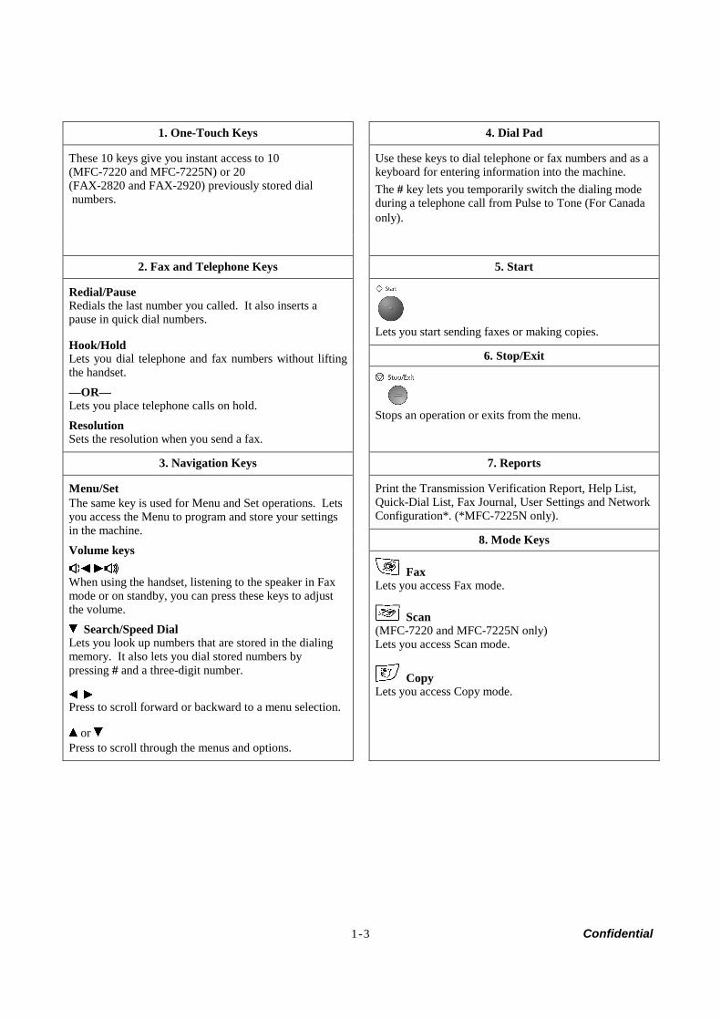
1. One-Touch Keys 4. Dial Pad
These 10 keys give you instant access to 10 (MFC-7220 and MFC-7225N) or 20 (FAX-2820 and FAX-2920) previously stored dial numbers.
Use these keys to dial telephone or fax numbers and as akeyboard for entering information into the machine. The # key lets you temporarily switch the dialing mode during a telephone call from Pulse to Tone (For Canada only).
2. Fax and Telephone Keys 5. Start
Lets you start sending faxes or making copies.
6. Stop/Exit
Redial/Pause Redials the last number you called. It also inserts a pause in quick dial numbers.
Hook/Hold Lets you dial telephone and fax numbers without lifting the handset.
—OR— Lets you place telephone calls on hold.
Resolution Sets the resolution when you send a fax.
Stops an operation or exits from the menu.
3. Navigation Keys 7. Reports
Print the Transmission Verification Report, Help List, Quick-Dial List, Fax Journal, User Settings and NetworkConfiguration*. (*MFC-7225N only).
8. Mode Keys
Menu/Set The same key is used for Menu and Set operations. Lets you access the Menu to program and store your settings in the machine.
Volume keys
When using the handset, listening to the speaker in Fax mode or on standby, you can press these keys to adjust the volume.
Search/Speed Dial Lets you look up numbers that are stored in the dialing memory. It also lets you dial stored numbers by pressing # and a three-digit number.
Press to scroll forward or backward to a menu selection.
or Press to scroll through the menus and options.
Fax Lets you access Fax mode.
Scan (MFC-7220 and MFC-7225N only) Lets you access Scan mode.
Copy Lets you access Copy mode.

1-4 Confidential
9. Liquid Crystal Display (LCD) 11. Shift (FAX-2820 and FAX-2920 only)
Displays messages on the screen to help you set up and use your machine.
To access One-Touch numbers 11 to 20, hold down Shift as you press the One-Touch key.
10. Copy Key (Temporary settings) 12. Printer Key (MFC-7220 and MFC-7225N only)
Options You can quickly and easily select temporary settings for copying.
Job Cancel You can cancel a print job and clear the printer memory.
manuals4you.commanuals4you.com
1-5 Confidential
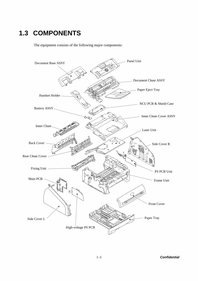
1.3 COMPONENTS The equipment consists of the following major components:
Document Chute ASSY
Panel Unit
Inner Chute Cover ASSY
Laser Unit
Side Cover R
PS PCB Unit
Frame Unit
Front Cover
Paper Tray
High-voltage PS PCB
Side Cover L
Main PCB
Fixing Unit
Back Cover
Rear Chute Cover
Buttery ASSY
Handset Holder
Document Base ASSY
Inner Chute
Paper Eject Tray
NCU PCB & Shield Case

Confidential
CHAPTER 2SPECIFICATIONS
manuals4you.commanuals4you.com
Confidential
CHAPTER 2 SPECIFICATIONS
This chapter lists the specifications of each model, which enables you to make a comparison of different models.
CONTENTS
2.1 GENERAL ........................................................................................................................2-1
2.1.1 General Specifications .........................................................................................2-1
2.1.2 Paper Specifications.............................................................................................2-2
2.1.3 Printable Area ................................................................................................................2-4
2.2 SPECIFICATIONS LIST...................................................................................................2-8
2-1 Confidential
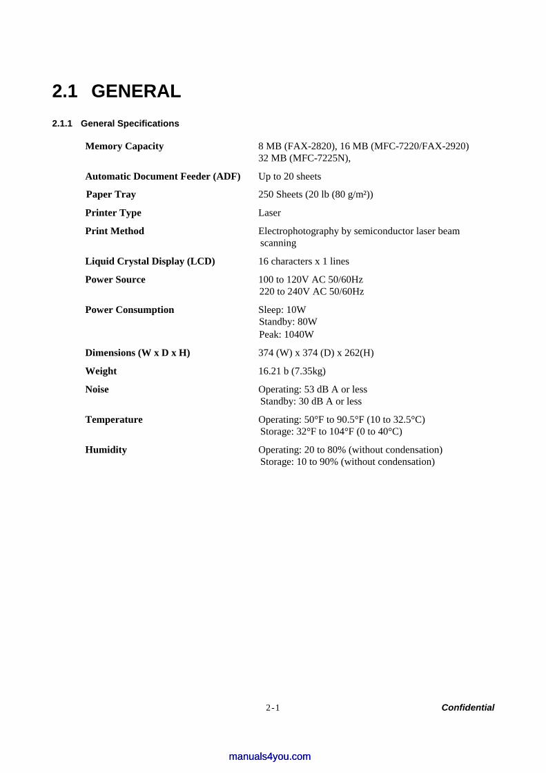
2.1 GENERAL 2.1.1 General Specifications
Memory Capacity 8 MB (FAX-2820), 16 MB (MFC-7220/FAX-2920) 32 MB (MFC-7225N),
Automatic Document Feeder (ADF) Up to 20 sheets
Paper Tray 250 Sheets (20 lb (80 g/m²))
Printer Type Laser
Print Method Electrophotography by semiconductor laser beam scanning
Liquid Crystal Display (LCD) 16 characters x 1 lines
Power Source 100 to 120V AC 50/60Hz 220 to 240V AC 50/60Hz
Power Consumption Sleep: 10W Standby: 80W Peak: 1040W
Dimensions (W x D x H) 374 (W) x 374 (D) x 262(H)
Weight 16.21 b (7.35kg)
Noise Operating: 53 dB A or less Standby: 30 dB A or less
Temperature Operating: 50°F to 90.5°F (10 to 32.5°C) Storage: 32°F to 104°F (0 to 40°C)
Humidity Operating: 20 to 80% (without condensation) Storage: 10 to 90% (without condensation)
manuals4you.commanuals4you.com
2-2 Confidential
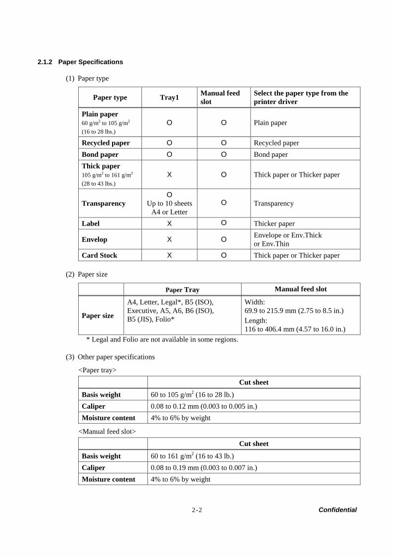
2.1.2 Paper Specifications
(1) Paper type
Paper type Tray1 Manual feed slot
Select the paper type from the printer driver
Plain paper 60 g/m2 to 105 g/m2
(16 to 28 lbs.) O O Plain paper
Recycled paper O O Recycled paper Bond paper O O Bond paper Thick paper 105 g/m2 to 161 g/m2
(28 to 43 lbs.) X O Thick paper or Thicker paper
Transparency O
Up to 10 sheets A4 or Letter
O Transparency
Label X O Thicker paper
Envelop X O Envelope or Env.Thick or Env.Thin
Card Stock X O Thick paper or Thicker paper
(2) Paper size
Paper Tray Manual feed slot
Paper size
A4, Letter, Legal*, B5 (ISO), Executive, A5, A6, B6 (ISO), B5 (JIS), Folio*
Width: 69.9 to 215.9 mm (2.75 to 8.5 in.) Length: 116 to 406.4 mm (4.57 to 16.0 in.)
* Legal and Folio are not available in some regions.
(3) Other paper specifications
<Paper tray>
Cut sheet
Basis weight 60 to 105 g/m2 (16 to 28 lb.) Caliper 0.08 to 0.12 mm (0.003 to 0.005 in.) Moisture content 4% to 6% by weight
<Manual feed slot>
Cut sheet
Basis weight 60 to 161 g/m2 (16 to 43 lb.) Caliper 0.08 to 0.19 mm (0.003 to 0.007 in.) Moisture content 4% to 6% by weight
2-3 Confidential
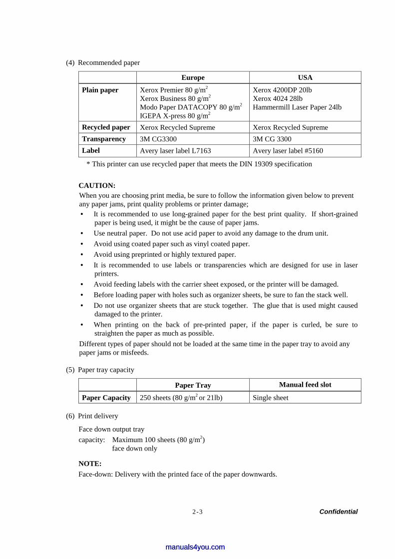
(4) Recommended paper
Europe USA
Plain paper Xerox Premier 80 g/m2
Xerox Business 80 g/m2
Modo Paper DATACOPY 80 g/m2
IGEPA X-press 80 g/m2
Xerox 4200DP 20lb Xerox 4024 28lb Hammermill Laser Paper 24lb
Recycled paper Xerox Recycled Supreme Xerox Recycled Supreme Transparency 3M CG3300 3M CG 3300 Label Avery laser label L7163 Avery laser label #5160
* This printer can use recycled paper that meets the DIN 19309 specification
CAUTION: When you are choosing print media, be sure to follow the information given below to prevent any paper jams, print quality problems or printer damage; • It is recommended to use long-grained paper for the best print quality. If short-grained
paper is being used, it might be the cause of paper jams. • Use neutral paper. Do not use acid paper to avoid any damage to the drum unit. • Avoid using coated paper such as vinyl coated paper. • Avoid using preprinted or highly textured paper. • It is recommended to use labels or transparencies which are designed for use in laser
printers. • Avoid feeding labels with the carrier sheet exposed, or the printer will be damaged. • Before loading paper with holes such as organizer sheets, be sure to fan the stack well. • Do not use organizer sheets that are stuck together. The glue that is used might caused
damaged to the printer. • When printing on the back of pre-printed paper, if the paper is curled, be sure to
straighten the paper as much as possible. Different types of paper should not be loaded at the same time in the paper tray to avoid any paper jams or misfeeds.
(5) Paper tray capacity
Paper Tray Manual feed slot
Paper Capacity 250 sheets (80 g/m2 or 21lb) Single sheet
(6) Print delivery
Face down output tray capacity: Maximum 100 sheets (80 g/m2)
face down only
NOTE: Face-down: Delivery with the printed face of the paper downwards.
manuals4you.commanuals4you.com
2-4 Confidential
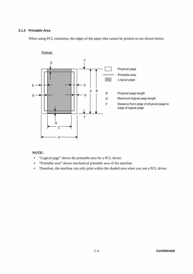
2.1.3 Printable Area
When using PCL emulation, the edges of the paper that cannot be printed on are shown below.
Portrait
A
B
C
D
E
F
GF
G
E
G G
Physical page
Printable area
Logical page
B Physical page length
D Maximum logical page length
F Distance from edge of physical page toedge of logical page
NOTE: • “Logical page” shows the printable area for a PCL driver. • “Printable area” shows mechanical printable area of the machine. • Therefore, the machine can only print within the shaded area when you use a PCL driver.
2-5 Confidential
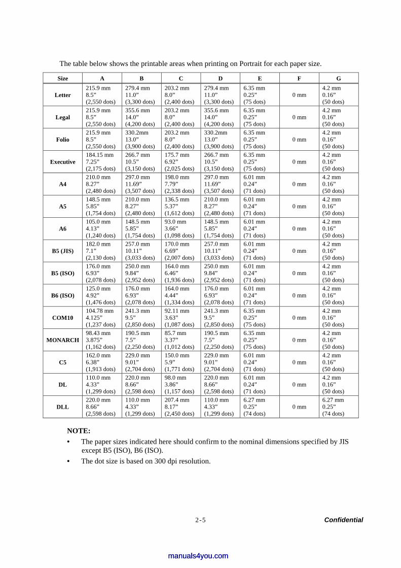
The table below shows the printable areas when printing on Portrait for each paper size.
Size A B C D E F G
Letter 215.9 mm 8.5” (2,550 dots)
279.4 mm 11.0” (3,300 dots)
203.2 mm 8.0” (2,400 dots)
279.4 mm 11.0” (3,300 dots)
6.35 mm 0.25” (75 dots)
0 mm 4.2 mm 0.16” (50 dots)
Legal 215.9 mm 8.5” (2,550 dots)
355.6 mm 14.0” (4,200 dots)
203.2 mm 8.0” (2,400 dots)
355.6 mm 14.0” (4,200 dots)
6.35 mm 0.25” (75 dots)
0 mm 4.2 mm 0.16” (50 dots)
Folio 215.9 mm 8.5” (2,550 dots)
330.2mm 13.0” (3,900 dots)
203.2 mm 8.0” (2,400 dots)
330.2mm 13.0” (3,900 dots)
6.35 mm 0.25” (75 dots)
0 mm 4.2 mm 0.16” (50 dots)
Executive 184.15 mm 7.25” (2,175 dots)
266.7 mm 10.5” (3,150 dots)
175.7 mm 6.92” (2,025 dots)
266.7 mm 10.5” (3,150 dots)
6.35 mm 0.25” (75 dots)
0 mm 4.2 mm 0.16” (50 dots)
A4 210.0 mm 8.27” (2,480 dots)
297.0 mm 11.69” (3,507 dots)
198.0 mm 7.79” (2,338 dots)
297.0 mm 11.69” (3,507 dots)
6.01 mm 0.24” (71 dots)
0 mm 4.2 mm 0.16” (50 dots)
A5 148.5 mm 5.85” (1,754 dots)
210.0 mm 8.27” (2,480 dots)
136.5 mm 5.37” (1,612 dots)
210.0 mm 8.27” (2,480 dots)
6.01 mm 0.24” (71 dots)
0 mm 4.2 mm 0.16” (50 dots)
A6 105.0 mm 4.13” (1,240 dots)
148.5 mm 5.85” (1,754 dots)
93.0 mm 3.66” (1,098 dots)
148.5 mm 5.85” (1,754 dots)
6.01 mm 0.24” (71 dots)
0 mm 4.2 mm 0.16” (50 dots)
B5 (JIS) 182.0 mm 7.1” (2,130 dots)
257.0 mm 10.11” (3,033 dots)
170.0 mm 6.69” (2,007 dots)
257.0 mm 10.11” (3,033 dots)
6.01 mm 0.24” (71 dots)
0 mm 4.2 mm 0.16” (50 dots)
B5 (ISO) 176.0 mm 6.93” (2,078 dots)
250.0 mm 9.84” (2,952 dots)
164.0 mm 6.46” (1,936 dots)
250.0 mm 9.84” (2,952 dots)
6.01 mm 0.24” (71 dots)
0 mm 4.2 mm 0.16” (50 dots)
B6 (ISO) 125.0 mm 4.92” (1,476 dots)
176.0 mm 6.93” (2,078 dots)
164.0 mm 4.44” (1,334 dots)
176.0 mm 6.93” (2,078 dots)
6.01 mm 0.24” (71 dots)
0 mm 4.2 mm 0.16” (50 dots)
COM10 104.78 mm 4.125” (1,237 dots)
241.3 mm 9.5” (2,850 dots)
92.11 mm 3.63” (1,087 dots)
241.3 mm 9.5” (2,850 dots)
6.35 mm 0.25” (75 dots)
0 mm 4.2 mm 0.16” (50 dots)
MONARCH 98.43 mm 3.875” (1,162 dots)
190.5 mm 7.5” (2,250 dots)
85.7 mm 3.37” (1,012 dots)
190.5 mm 7.5” (2,250 dots)
6.35 mm 0.25” (75 dots)
0 mm 4.2 mm 0.16” (50 dots)
C5 162.0 mm 6.38” (1,913 dots)
229.0 mm 9.01” (2,704 dots)
150.0 mm 5.9” (1,771 dots)
229.0 mm 9.01” (2,704 dots)
6.01 mm 0.24” (71 dots)
0 mm 4.2 mm 0.16” (50 dots)
DL 110.0 mm 4.33” (1,299 dots)
220.0 mm 8.66” (2,598 dots)
98.0 mm 3.86” (1,157 dots)
220.0 mm 8.66” (2,598 dots)
6.01 mm 0.24” (71 dots)
0 mm 4.2 mm 0.16” (50 dots)
DLL 220.0 mm 8.66” (2,598 dots)
110.0 mm 4.33” (1,299 dots)
207.4 mm 8.17” (2,450 dots)
110.0 mm 4.33” (1,299 dots)
6.27 mm 0.25” (74 dots)
0 mm 6.27 mm 0.25” (74 dots)
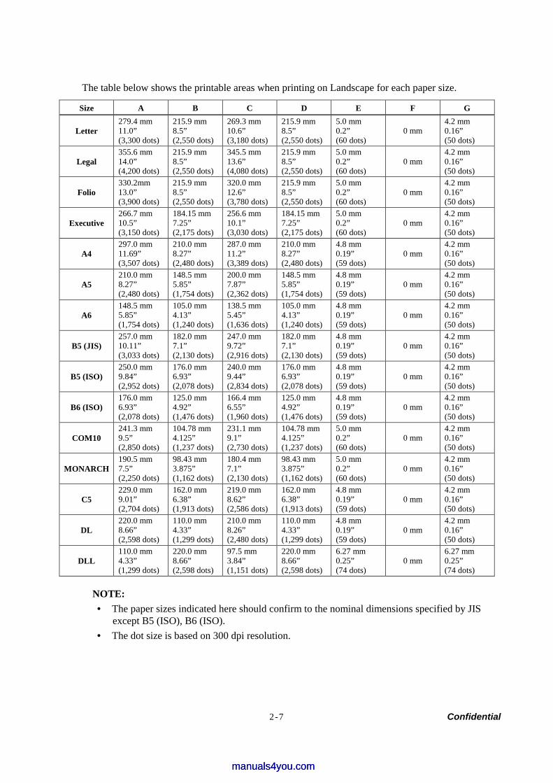
NOTE: • The paper sizes indicated here should confirm to the nominal dimensions specified by JIS
except B5 (ISO), B6 (ISO). • The dot size is based on 300 dpi resolution.
manuals4you.commanuals4you.com
2-6 Confidential
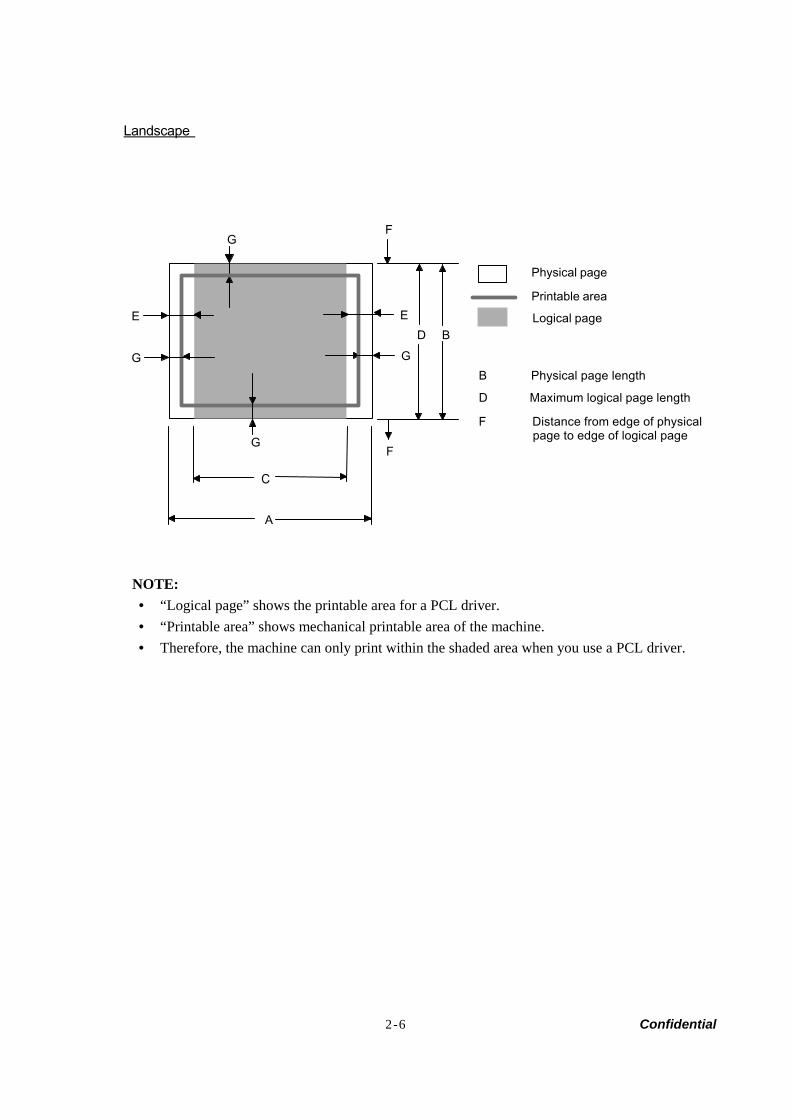
Landscape
A
B
C
D
E
F
GF
G
E
G G
Physical page
Printable area
Logical page
B Physical page length
D Maximum logical page length
F Distance from edge of physical page to edge of logical page
NOTE: • “Logical page” shows the printable area for a PCL driver. • “Printable area” shows mechanical printable area of the machine. • Therefore, the machine can only print within the shaded area when you use a PCL driver.
2-7 Confidential
The table below shows the printable areas when printing on Landscape for each paper size.
Size A B C D E F G
Letter 279.4 mm 11.0” (3,300 dots)
215.9 mm 8.5” (2,550 dots)
269.3 mm 10.6” (3,180 dots)
215.9 mm 8.5” (2,550 dots)
5.0 mm 0.2” (60 dots)
0 mm 4.2 mm 0.16” (50 dots)
Legal 355.6 mm 14.0” (4,200 dots)
215.9 mm 8.5” (2,550 dots)
345.5 mm 13.6” (4,080 dots)
215.9 mm 8.5” (2,550 dots)
5.0 mm 0.2” (60 dots)
0 mm 4.2 mm 0.16” (50 dots)
Folio 330.2mm 13.0” (3,900 dots)
215.9 mm 8.5” (2,550 dots)
320.0 mm 12.6” (3,780 dots)
215.9 mm 8.5” (2,550 dots)
5.0 mm 0.2” (60 dots)
0 mm 4.2 mm 0.16” (50 dots)
Executive 266.7 mm 10.5” (3,150 dots)
184.15 mm 7.25” (2,175 dots)
256.6 mm 10.1” (3,030 dots)
184.15 mm 7.25” (2,175 dots)
5.0 mm 0.2” (60 dots)
0 mm 4.2 mm 0.16” (50 dots)
A4 297.0 mm 11.69” (3,507 dots)
210.0 mm 8.27” (2,480 dots)
287.0 mm 11.2” (3,389 dots)
210.0 mm 8.27” (2,480 dots)
4.8 mm 0.19” (59 dots)
0 mm 4.2 mm 0.16” (50 dots)
A5 210.0 mm 8.27” (2,480 dots)
148.5 mm 5.85” (1,754 dots)
200.0 mm 7.87” (2,362 dots)
148.5 mm 5.85” (1,754 dots)
4.8 mm 0.19” (59 dots)
0 mm 4.2 mm 0.16” (50 dots)
A6 148.5 mm 5.85” (1,754 dots)
105.0 mm 4.13” (1,240 dots)
138.5 mm 5.45” (1,636 dots)
105.0 mm 4.13” (1,240 dots)
4.8 mm 0.19” (59 dots)
0 mm 4.2 mm 0.16” (50 dots)
B5 (JIS) 257.0 mm 10.11” (3,033 dots)
182.0 mm 7.1” (2,130 dots)
247.0 mm 9.72” (2,916 dots)
182.0 mm 7.1” (2,130 dots)
4.8 mm 0.19” (59 dots)
0 mm 4.2 mm 0.16” (50 dots)
B5 (ISO) 250.0 mm 9.84” (2,952 dots)
176.0 mm 6.93” (2,078 dots)
240.0 mm 9.44” (2,834 dots)
176.0 mm 6.93” (2,078 dots)
4.8 mm 0.19” (59 dots)
0 mm 4.2 mm 0.16” (50 dots)
B6 (ISO) 176.0 mm 6.93” (2,078 dots)
125.0 mm 4.92” (1,476 dots)
166.4 mm 6.55” (1,960 dots)
125.0 mm 4.92” (1,476 dots)
4.8 mm 0.19” (59 dots)
0 mm 4.2 mm 0.16” (50 dots)
COM10 241.3 mm 9.5” (2,850 dots)
104.78 mm 4.125” (1,237 dots)
231.1 mm 9.1” (2,730 dots)
104.78 mm 4.125” (1,237 dots)
5.0 mm 0.2” (60 dots)
0 mm 4.2 mm 0.16” (50 dots)
MONARCH 190.5 mm 7.5” (2,250 dots)
98.43 mm 3.875” (1,162 dots)
180.4 mm 7.1” (2,130 dots)
98.43 mm 3.875” (1,162 dots)
5.0 mm 0.2” (60 dots)
0 mm 4.2 mm 0.16” (50 dots)
C5 229.0 mm 9.01” (2,704 dots)
162.0 mm 6.38” (1,913 dots)
219.0 mm 8.62” (2,586 dots)
162.0 mm 6.38” (1,913 dots)
4.8 mm 0.19” (59 dots)
0 mm 4.2 mm 0.16” (50 dots)
DL 220.0 mm 8.66” (2,598 dots)
110.0 mm 4.33” (1,299 dots)
210.0 mm 8.26” (2,480 dots)
110.0 mm 4.33” (1,299 dots)
4.8 mm 0.19” (59 dots)
0 mm 4.2 mm 0.16” (50 dots)
DLL 110.0 mm 4.33” (1,299 dots)
220.0 mm 8.66” (2,598 dots)
97.5 mm 3.84” (1,151 dots)
220.0 mm 8.66” (2,598 dots)
6.27 mm 0.25” (74 dots)
0 mm 6.27 mm 0.25” (74 dots)
NOTE: • The paper sizes indicated here should confirm to the nominal dimensions specified by JIS
except B5 (ISO), B6 (ISO). • The dot size is based on 300 dpi resolution.
manuals4you.commanuals4you.com
2-8 Confidential
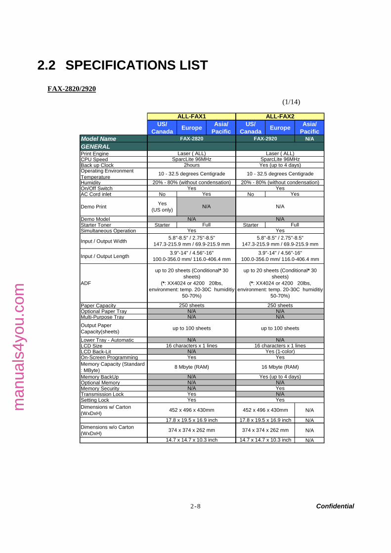
2.2 SPECIFICATIONS LIST FAX-2820/2920
(1/14)
US/Canada Europe Asia/
PacificUS/
Canada Europe Asia/Pacific
Model Name N/AGENERAL Print EngineCPU Speed Back up ClockOperating EnvironmentTemperatureHumidityOn/Off SwitchAC Cord inlet No No
Demo Print Yes(US only)
Demo Model Starter Toner Starter StarterSimultaneous Operation
Input / Output Width
Input / Output Length
ADF
Paper CapacityOptional Paper TrayMulti-Purpose TrayOutput PaperCapacity(sheets)Lower Tray - AutomaticLCD SizeLCD Back-LitOn-Screen ProgrammingMemory Capacity (Standard: MByte)Memory BackUpOptional MemoryMemory SecurityTransmission LockSetting LockDimensions w/ Carton(WxDxH) N/A
N/ADimensions w/o Carton(WxDxH) N/A
N/A
374 x 374 x 262 mm 374 x 374 x 262 mm
14.7 x 14.7 x 10.3 inch 14.7 x 14.7 x 10.3 inch
452 x 496 x 430mm
17.8 x 19.5 x 16.9 inch
Yes Yes
17.8 x 19.5 x 16.9 inch
FAX-2920
SparcLite 96MHz
Yes Yes
Yes (up to 4 days)10 - 32.5 degrees Centigrade
20% - 80% (without condensation)10 - 32.5 degrees Centigrade
20% - 80% (without condensation)
N/AYes N/A
YesYes
250 sheets
N/A
8 Mbyte (RAM)
N/AN/A
ALL-FAX1
Laser ( ALL)SparcLite 96MHz
2hours
FAX-2820
ALL-FAX2
Laser ( ALL)
N/A
up to 20 sheets (Conditional* 30sheets)
(*: XX4024 or 4200 20lbs,environment: temp. 20-30C humiditiy
50-70%)
N/A
Yes
N/A
YesFull Full
N/A
5.8"-8.5" / 2.75"-8.5"147.3-215.9 mm / 69.9-215.9 mm
Yes (up to 4 days)
Yes
up to 100 sheets
N/AN/A
Yes
3.9"-14" / 4.56"-16"100.0-356.0 mm/ 116.0-406.4 mm
up to 100 sheets
16 characters x 1 lines
N/A
452 x 496 x 430mm
3.9"-14" / 4.56"-16"100.0-356.0 mm/ 116.0-406.4 mm
16 characters x 1 linesYes (1-color)
N/AN/A
N/A
Yes
N/A
16 Mbyte (RAM)
up to 20 sheets (Conditional* 30sheets)
(*: XX4024 or 4200 20lbs,environment: temp. 20-30C humiditiy
50-70%)
250 sheets
5.8"-8.5" / 2.75"-8.5"147.3-215.9 mm / 69.9-215.9 mm
man
uals
4you
.com
man
uals
4you
.com
2-9 Confidential
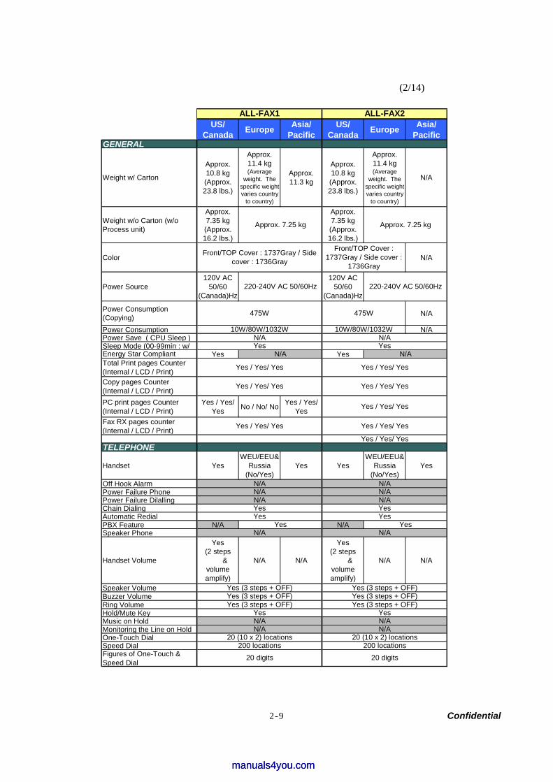
(2/14)
US/Canada Europe Asia/
PacificUS/
Canada Europe Asia/Pacific
GENERAL
Weight w/ Carton
Approx.10.8 kg(Approx.23.8 lbs.)
Approx.11.4 kg(Average
weight. Thespecific weightvaries country
to country)
Approx.11.3 kg
Approx.10.8 kg(Approx.23.8 lbs.)
Approx.11.4 kg(Average
weight. Thespecific weightvaries country
to country)
N/A
Weight w/o Carton (w/oProcess unit)
Approx.7.35 kg(Approx.16.2 lbs.)
Approx.7.35 kg(Approx.16.2 lbs.)
Color N/A
Power Source120V AC
50/60(Canada)Hz
120V AC50/60
(Canada)Hz
Power Consumption(Copying) N/A
Power Consumption N/APower Save ( CPU Sleep )Sleep Mode (00-99min : w/Energy Star Compliant Yes YesTotal Print pages Counter(Internal / LCD / Print)Copy pages Counter(Internal / LCD / Print)PC print pages Counter(Internal / LCD / Print)
Yes / Yes/Yes No / No/ No Yes / Yes/
YesFax RX pages counter(Internal / LCD / Print)
TELEPHONE
Handset YesWEU/EEU&
Russia(No/Yes)
Yes YesWEU/EEU&
Russia(No/Yes)
Yes
Off Hook Alarm Power Failure Phone Power Failure Dilalling Chain DialingAutomatic RedialPBX Feature N/A N/ASpeaker Phone
Handset Volume
Yes(2 steps &
volumeamplify)
N/A N/A
Yes(2 steps &
volumeamplify)
N/A N/A
Speaker VolumeBuzzer VolumeRing VolumeHold/Mute KeyMusic on Hold Monitoring the Line on HoldOne-Touch DialSpeed DialFigures of One-Touch &Speed Dial
Yes (3 steps + OFF)Yes (3 steps + OFF)
N/A
Yes / Yes/ Yes
Yes / Yes/ Yes
N/A
200 locations20 digits
20 (10 x 2) locations
ALL-FAX2ALL-FAX1
N/A
Yes / Yes/ Yes
N/AN/A
N/A
N/AN/A
N/AYes
YesYes
Yes Yes
10W/80W/1032W 10W/80W/1032W
Approx. 7.25 kg
475W
Front/TOP Cover : 1737Gray / Sidecover : 1736Gray
Approx. 7.25 kg
220-240V AC 50/60Hz
475W
220-240V AC 50/60Hz
Yes
N/A N/A
Yes / Yes/ Yes
Yes / Yes/ Yes
Yes
Yes (3 steps + OFF)
Yes
Yes
Front/TOP Cover :1737Gray / Side cover :
1736Gray
N/A
N/A
Yes / Yes/ Yes
Yes / Yes/ Yes
Yes / Yes/ Yes
200 locations20 digits
N/A
Yes (3 steps + OFF)Yes (3 steps + OFF)
N/AN/A
20 (10 x 2) locations
Yes (3 steps + OFF)
Yes
manuals4you.commanuals4you.com
2-10 Confidential
(3/14)
US/Canada Europe Asia/
PacificUS/
Canada Europe Asia/Pacific
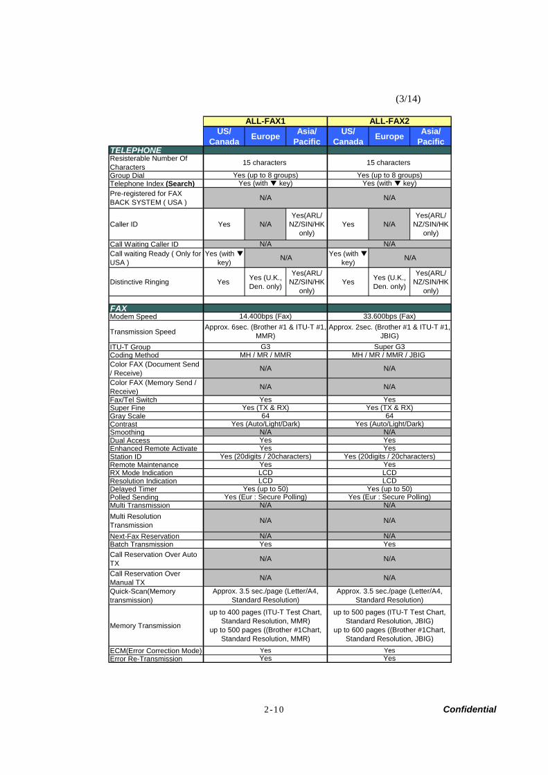
TELEPHONEResisterable Number OfCharactersGroup Dial Telephone Index (Search)Pre-registered for FAXBACK SYSTEM ( USA )
Caller ID Yes N/AYes(ARL/
NZ/SIN/HKonly)
Yes N/AYes(ARL/
NZ/SIN/HKonly)
Call Waiting Caller IDCall waiting Ready ( Only forUSA )
Yes (with key)
Yes (with key)
Distinctive Ringing Yes Yes (U.K.,Den. only)
Yes(ARL/NZ/SIN/HK
only)Yes Yes (U.K.,
Den. only)
Yes(ARL/NZ/SIN/HK
only)
FAXModem Speed
Transmission Speed
ITU-T GroupCoding MethodColor FAX (Document Send/ Receive)Color FAX (Memory Send /Receive)Fax/Tel SwitchSuper FineGray ScaleContrastSmoothingDual AccessEnhanced Remote ActivateStation IDRemote MaintenanceRX Mode IndicationResolution IndicationDelayed TimerPolled SendingMulti TransmissionMulti ResolutionTransmissionNext-Fax ReservationBatch TransmissionCall Reservation Over AutoTXCall Reservation OverManual TXQuick-Scan(Memorytransmission)
Memory Transmission
ECM(Error Correction Mode)Error Re-Transmission
ALL-FAX2
N/A
Yes (with key)
ALL-FAX1
N/A
Yes (up to 8 groups)
15 characters
N/A
N/A
YesYes
N/A
N/A
Approx. 3.5 sec./page (Letter/A4,Standard Resolution)
up to 500 pages (ITU-T Test Chart,Standard Resolution, JBIG)
up to 600 pages ((Brother #1Chart,Standard Resolution, JBIG)
Approx. 3.5 sec./page (Letter/A4,Standard Resolution)
up to 400 pages (ITU-T Test Chart,Standard Resolution, MMR)
up to 500 pages ((Brother #1Chart,Standard Resolution, MMR)
YesYes
N/A
N/A
Yes (up to 50)Yes (Eur : Secure Polling)
N/A
N/A
N/A
Yes
N/A
Yes
Yes (20digits / 20characters)
LCD
YesLCD
Yes (20digits / 20characters)Yes
LCDLCD
64
Yes
Yes YesYesN/A
Yes (Auto/Light/Dark)N/AYes
Yes (TX & RX)Yes (TX & RX)
N/A
Yes
N/A
MH / MR / MMRG3
14.400bps (Fax)Approx. 6sec. (Brother #1 & ITU-T #1,
MMR)
MH / MR / MMR / JBIG Super G3
N/A
33.600bps (Fax)Approx. 2sec. (Brother #1 & ITU-T #1,
JBIG)
N/A
Yes (up to 8 groups)
Yes (up to 50)
N/A
N/A
15 characters
64Yes (Auto/Light/Dark)
N/A
N/A
Yes (Eur : Secure Polling)
Yes (with key)
2-11 Confidential
(4/14)
US/Canada Europe Asia/
PacificUS/
Canada Europe Asia/Pacific
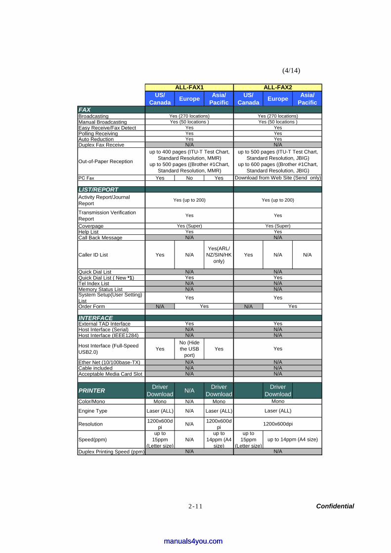
FAXBroadcastingManual BroadcastingEasy Receive/Fax DetectPolling Receiving Auto ReductionDuplex Fax Receive
Out-of-Paper Reception
PC Fax Yes No Yes
LIST/REPORTActivity Report/JournalReport
Transmission VerificationReportCoverpageHelp ListCall Back Message
Caller ID List Yes N/AYes(ARL/
NZ/SIN/HKonly)
Yes N/A N/A
Quick Dial ListQuick Dial List ( New *1)Tel Index ListMemory Status List System Setup(User Setting)ListOrder Form N/A N/A
INTERFACEExternal TAD InterfaceHost Interface (Serial)Host Interface (IEEE1284)
Host Interface (Full-SpeedUSB2.0) Yes
No (Hidethe USB
port)Yes
Ether Net (10/100base-TX)Cable includedAcceptable Media Card Slot
PRINTER DriverDownload N/A Driver
DownloadDriver
DownloadColor/Mono Mono N/A Mono
Engine Type Laser (ALL) N/A Laser (ALL)
Resolution 1200x600dpi N/A 1200x600d
pi
Speed(ppm)up to
15ppm(Letter size)
N/Aup to
14ppm (A4size)
up to15ppm
(Letter size)Duplex Printing Speed (ppm)
1200x600dpi
Yes
N/Aup to 400 pages (ITU-T Test Chart,
Standard Resolution, MMR)up to 500 pages ((Brother #1Chart,
Standard Resolution, MMR)
Yes (up to 200)
Yes
Yes (Super)
Mono
N/A
Download from Web Site (Send only)
N/A
N/AN/A
up to 14ppm (A4 size)
N/A
N/A
N/AN/A
N/AN/A
ALL-FAX2ALL-FAX1
Yes
Laser (ALL)
Yes
Yes
N/A
N/A
N/AN/A
YesYes
Yes
Yes (Super)Yes
N/A
N/A
N/AYes
N/A
Yes (up to 200)
Yes
Yes (270 locations)Yes (50 locations )
up to 500 pages (ITU-T Test Chart,Standard Resolution, JBIG)
up to 600 pages ((Brother #1Chart,Standard Resolution, JBIG)
YesYesN/A
YesYes (50 locations )Yes (270 locations)
Yes
N/A
YesYes
Yes
N/A
Yes
manuals4you.commanuals4you.com
2-12 Confidential
(5/14)
US/Canada Europe Asia/
PacificUS/
Canada Europe Asia/Pacific
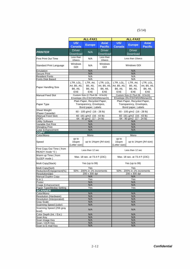
PRINTER DriverDownload N/A Driver
DownloadDriver
DownloadFirst Print Out Time Less than
10secs N/A Less than10secs
Standard Print Language WindowsGDI N/A Windows
GDIEmulationSecure PrintResident FontsFonts Disk Based
Paper Handling Size
LTR, LGL,A4, B5, A5,
B6, A6,EXE
LTR, A4,B5, A5,B6, A6,
EXE
LTR, LGL,A4, B5, A5,
B6, A6,EXE
LTR, LGL,A4, B5, A5,
B6, A6,EXE
LTR, A4,B5, A5,B6, A6,
EXE
LTR, LGL,A4, B5, A5,
B6, A6,EXE
Manual Feed Slot
Paper Type
Sheet Weight(Paper Cassette)(Manual Feed Slot)(ADF)Utility SoftwareVariable Dot PrintShingling PrintColor EnhancementCOPYColor/Mono
Speedup to
15cpm(Letter size)
up to15cpm
(Letter size)First Copy Out Time ( fromREADY mode *2 )Warm up Time ( fromSLEEP mode )
Multi Copy(Stack)
Multi Copy(Sort)Reduction/Enlargement(%)Resolution(dpi)Manual Duplex Copy N in 1PosterImage EnhancementPaper Type(Media) Setting SCANNERColor/MonoResolution (Hardware)Resolution (Interporated)Gray ScaleScanning Speed (color)Scanning Speed (256 graylevel)Color Depth (Int. / Ext.)Scan KeyScan Image KeyScan / OCR KeyScan to E-mail Key
N/AN/A
Less than 10secs
Windows GDI
N/AN/A
N/A
60 - 105 g/m2 (16 - 28 lb)60 -161 g/m2 (16 - 43 lb)
Plain Paper, Recycled Paper,Transparency, Envelopes,
Bond paper, Labels
N/A
up to 14cpm (A4 size)
Less than 12 sec
Yes
N/A
N/AYes
up to 14cpm (A4 size)
Less than 12 sec
N/A
Custom Size (2.75x4.56 - 8.5x16) Envelope (DL/C5/CM10/Monarch)
Yes
N/A
50% - 200% in 1% increments200 x 300 dpi
N/A
N/A
N/A
N/A
64 - 90 g/m2 (17 - 24 lb)
N/A
Custom Size (2.75x4.56 - 8.5x16) Envelope (DL/C5/CM10/Monarch)
60 -161 g/m2 (16 - 43 lb)
N/A
60 - 105 g/m2 (16 - 28 lb)
Plain Paper, Recycled Paper,Transparency, Envelopes,
Bond paper, Labels
N/A
Yes
N/AN/A N/A
N/A
N/A
N/A
50% - 200% in 1% increments200 x 300 dpi
Yes (up to 99)
Yes
Max. 18 sec. at 73.4 F (23C)
Mono
N/A
N/A
Yes
N/A
N/A
N/A
N/A
N/A
N/AN/A
N/A
N/AN/A
N/A
ALL-FAX2
N/A
ALL-FAX1
N/A
64 - 90 g/m2 (17 - 24 lb)
Yes (up to 99)
N/A
N/AN/AN/A
Max. 18 sec. at 73.4 F (23C)
Mono
N/A
N/A
2-13 Confidential
(6/14)
US/Canada Europe Asia/
PacificUS/
Canada Europe Asia/Pacific
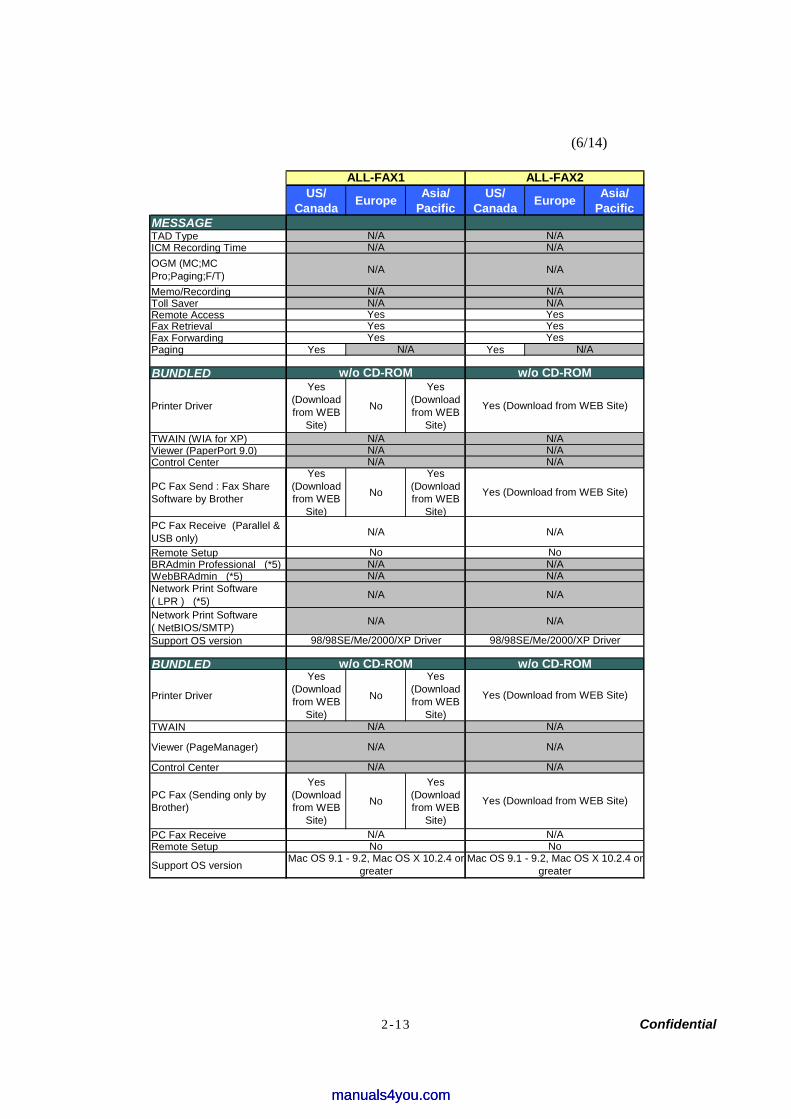
MESSAGETAD TypeICM Recording TimeOGM (MC;MCPro;Paging;F/T)Memo/RecordingToll SaverRemote AccessFax RetrievalFax ForwardingPaging Yes Yes
BUNDLED
Printer Driver
Yes(Downloadfrom WEB
Site)
No
Yes(Downloadfrom WEB
Site)TWAIN (WIA for XP)Viewer (PaperPort 9.0)Control Center
PC Fax Send : Fax ShareSoftware by Brother
Yes(Downloadfrom WEB
Site)
No
Yes(Downloadfrom WEB
Site)PC Fax Receive (Parallel &USB only) N/A N/A
Remote SetupBRAdmin Professional (*5)WebBRAdmin (*5)Network Print Software( LPR ) (*5)Network Print Software( NetBIOS/SMTP)Support OS version
BUNDLED
Printer Driver
Yes(Downloadfrom WEB
Site)
No
Yes(Downloadfrom WEB
Site)TWAIN
Viewer (PageManager)
Control Center
PC Fax (Sending only byBrother)
Yes(Downloadfrom WEB
Site)
No
Yes(Downloadfrom WEB
Site)PC Fax ReceiveRemote Setup
Support OS version
N/A
N/A
N/A
N/A
Yes
w/o CD-ROM w/o CD-ROM
Yes
N/A
Yes (Download from WEB Site)
Yes (Download from WEB Site)
N/AN/A
w/o CD-ROM
98/98SE/Me/2000/XP Driver
N/A
N/A
N/A
NoN/A
N/A
N/A
N/A
Yes (Download from WEB Site)
N/A
N/A
NoN/A
Yes (Download from WEB Site)
Mac OS 9.1 - 9.2, Mac OS X 10.2.4 orgreater
Mac OS 9.1 - 9.2, Mac OS X 10.2.4 orgreater
N/A
N/A
ALL-FAX2
w/o CD-ROM
Yes
N/A
N/A
N/A
N/A
N/A
98/98SE/Me/2000/XP Driver
No
N/A
N/AYesYes
N/A
Yes
N/A
No
ALL-FAX1
N/A
N/A
N/AN/A
N/A
N/A
manuals4you.commanuals4you.com
2-14 Confidential
(7/14)
US/Canada Europe Asia/
PacificUS/
Canada Europe Asia/Pacific
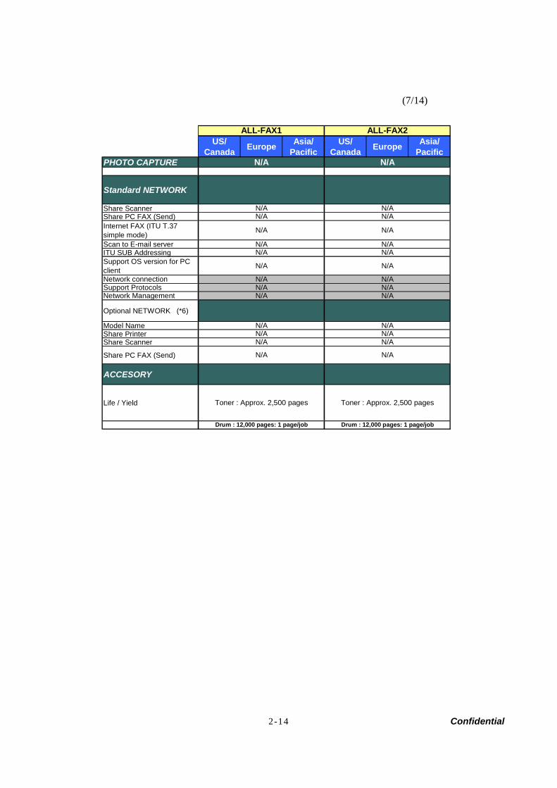
PHOTO CAPTURE N/A N/A
Standard NETWORK
Share ScannerShare PC FAX (Send)Internet FAX (ITU T.37simple mode)Scan to E-mail server N/A N/AITU SUB Addressing Support OS version for PCclientNetwork connection Support ProtocolsNetwork Management
Optional NETWORK (*6)
Model NameShare PrinterShare Scanner
Share PC FAX (Send)
ACCESORY
Life / Yield
Drum : 12,000 pages: 1 page/job
N/AN/AN/A
Toner : Approx. 2,500 pages
N/A
N/AN/A
N/AN/A
ALL-FAX2ALL-FAX1
N/A
N/A
Drum : 12,000 pages: 1 page/job
N/A
Toner : Approx. 2,500 pages
N/A
N/AN/AN/A
N/A
N/A N/A
N/A N/A
N/AN/A
N/AN/A
2-15 Confidential
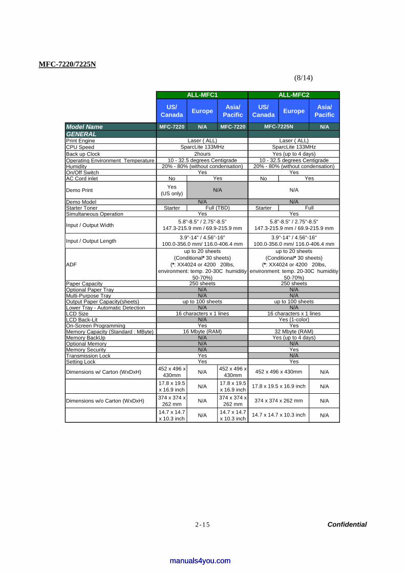
MFC-7220/7225N
(8/14)
US/Canada Europe Asia/
PacificUS/
Canada Europe Asia/Pacific
Model Name MFC-7220 N/A MFC-7220 N/AGENERAL Print EngineCPU Speed Back up ClockOperating Environment TemperatureHumidityOn/Off SwitchAC Cord inlet No No
Demo Print Yes(US only)
Demo Model Starter Toner Starter StarterSimultaneous Operation
Input / Output Width
Input / Output Length
ADF
Paper CapacityOptional Paper TrayMulti-Purpose TrayOutput Paper Capacity(sheets)Lower Tray - Automatic Detection LCD SizeLCD Back-LitOn-Screen ProgrammingMemory Capacity (Standard : MByte)Memory BackUpOptional MemoryMemory SecurityTransmission LockSetting Lock
Dimensions w/ Carton (WxDxH) 452 x 496 x430mm N/A 452 x 496 x
430mm N/A
17.8 x 19.5x 16.9 inch N/A 17.8 x 19.5
x 16.9 inch N/A
Dimensions w/o Carton (WxDxH) 374 x 374 x262 mm N/A 374 x 374 x
262 mm N/A
14.7 x 14.7x 10.3 inch N/A 14.7 x 14.7
x 10.3 inch N/A
Full
N/A
N/A
N/A
Yes
3.9"-14" / 4.56"-16"100.0-356.0 mm/ 116.0-406.4 mm
250 sheetsN/A
3.9"-14" / 4.56"-16"100.0-356.0 mm/ 116.0-406.4 mm
up to 100 sheets
ALL-MFC2
Laser ( ALL)SparcLite 133MHz
up to 20 sheets(Conditional* 30 sheets)
(*: XX4024 or 4200 20lbs,environment: temp. 20-30C humiditiy
50-70%)
Yes (up to 4 days)10 - 32.5 degrees Centigrade
20% - 80% (without condensation)
N/A
Yes
Yes
ALL-MFC1
10 - 32.5 degrees Centigrade
up to 20 sheets(Conditional* 30 sheets)
(*: XX4024 or 4200 20lbs,environment: temp. 20-30C humiditiy
50-70%)
Yes
SparcLite 133MHzLaser ( ALL)
Yes
N/AFull (TBD)
250 sheetsN/AN/A
Yes (1-color)16 characters x 1 lines
452 x 496 x 430mm
374 x 374 x 262 mm
17.8 x 19.5 x 16.9 inch
up to 100 sheetsN/A
Yes
N/A16 characters x 1 lines
N/AN/AYes
Yes
Yes
16 Mbyte (RAM)Yes
32 Mbyte (RAM)Yes (up to 4 days)
N/AYes
14.7 x 14.7 x 10.3 inch
MFC-7225N
5.8"-8.5" / 2.75"-8.5"147.3-215.9 mm / 69.9-215.9 mm
N/AN/A
5.8"-8.5" / 2.75"-8.5"147.3-215.9 mm / 69.9-215.9 mm
2hours
20% - 80% (without condensation)Yes
N/A
manuals4you.commanuals4you.com
2-16 Confidential
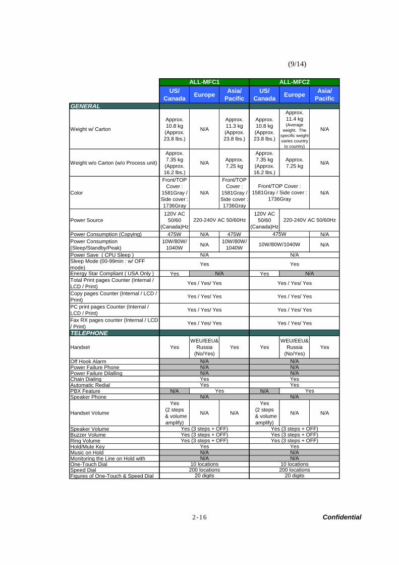
(9/14)
US/Canada Europe Asia/
PacificUS/
Canada Europe Asia/Pacific
GENERAL
Weight w/ Carton
Approx.10.8 kg(Approx.23.8 lbs.)
N/A
Approx.11.3 kg(Approx.23.8 lbs.)
Approx.10.8 kg(Approx.23.8 lbs.)
Approx.11.4 kg(Average
weight. Thespecific weightvaries country
to country)
N/A
Weight w/o Carton (w/o Process unit)
Approx.7.35 kg(Approx.16.2 lbs.)
N/A Approx.7.25 kg
Approx.7.35 kg(Approx.16.2 lbs.)
Approx.7.25 kg N/A
Color
Front/TOPCover :
1581Gray /Side cover :1736Gray
N/A
Front/TOPCover :
1581Gray /Side cover :1736Gray
N/A
Power Source120V AC
50/60(Canada)Hz
120V AC50/60
(Canada)HzPower Consumption (Copying) 475W N/A 475W N/APower Consumption(Sleep/Standby/Peak)
10W/80W/1040W N/A 10W/80W/
1040W N/A
Power Save ( CPU Sleep )Sleep Mode (00-99min : w/ OFFmode)Energy Star Compliant ( USA Only ) Yes YesTotal Print pages Counter (Internal /LCD / Print)Copy pages Counter (Internal / LCD /Print)PC print pages Counter (Internal /LCD / Print)Fax RX pages counter (Internal / LCD/ Print)TELEPHONE
Handset YesWEU/EEU&
Russia(No/Yes)
Yes YesWEU/EEU&
Russia(No/Yes)
Yes
Off Hook Alarm Power Failure Phone Power Failure Dilalling Chain DialingAutomatic RedialPBX Feature N/A N/ASpeaker Phone
Handset Volume
Yes(2 steps
& volumeamplify)
N/A N/A
Yes(2 steps
& volumeamplify)
N/A N/A
Speaker VolumeBuzzer VolumeRing VolumeHold/Mute KeyMusic on Hold Monitoring the Line on Hold withOne-Touch DialSpeed DialFigures of One-Touch & Speed Dial 20 digits
N/A
220-240V AC 50/60Hz
N/A
Yes (3 steps + OFF)Yes (3 steps + OFF)
Yes
Yes / Yes/ Yes
Yes / Yes/ Yes
Yes
20 digits
Yes (3 steps + OFF)
Yes (3 steps + OFF)
N/A10 locations
N/AYes
200 locations
Yes (3 steps + OFF)
Yes
N/AN/A
YesYesN/A
Yes / Yes/ Yes
N/A
Yes / Yes/ Yes
Yes / Yes/ Yes
N/A
200 locations
N/A
Yes (3 steps + OFF)
N/A
10 locations
YesYes
ALL-MFC1
Yes
N/A
N/A
Yes / Yes/ Yes
Yes / Yes/ Yes
N/A
ALL-MFC2
475W
Yes / Yes/ Yes
220-240V AC 50/60Hz
N/A
10W/80W/1040W
N/A
Yes
Front/TOP Cover :1581Gray / Side cover :
1736Gray
2-17 Confidential
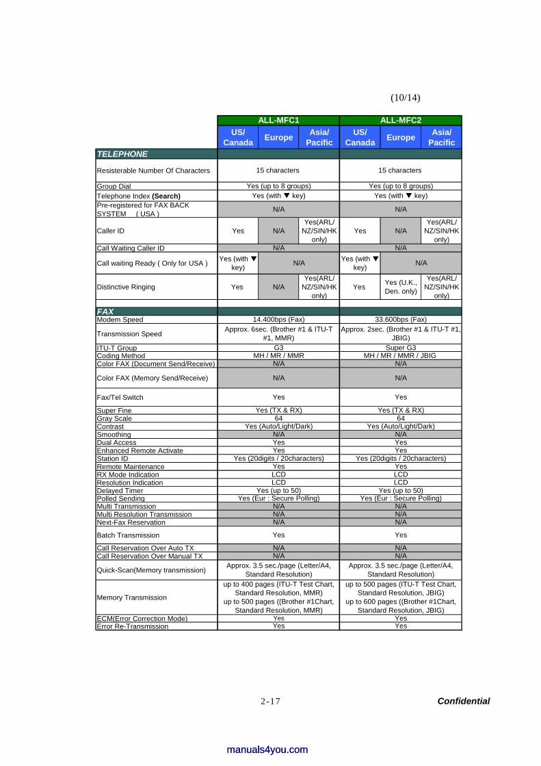
(10/14)
US/Canada Europe Asia/
PacificUS/
Canada Europe Asia/Pacific
TELEPHONE
Resisterable Number Of Characters
Group Dial Telephone Index (Search)Pre-registered for FAX BACKSYSTEM ( USA )
Caller ID Yes N/AYes(ARL/
NZ/SIN/HKonly)
Yes N/AYes(ARL/
NZ/SIN/HKonly)
Call Waiting Caller ID
Call waiting Ready ( Only for USA ) Yes (with key)
Yes (with key)
Distinctive Ringing Yes N/AYes(ARL/
NZ/SIN/HKonly)
Yes Yes (U.K.,Den. only)
Yes(ARL/NZ/SIN/HK
only)
FAXModem Speed
Transmission Speed
ITU-T GroupCoding MethodColor FAX (Document Send/Receive)
Color FAX (Memory Send/Receive)
Fax/Tel Switch
Super FineGray ScaleContrastSmoothingDual AccessEnhanced Remote ActivateStation IDRemote MaintenanceRX Mode IndicationResolution IndicationDelayed TimerPolled SendingMulti TransmissionMulti Resolution TransmissionNext-Fax Reservation
Batch Transmission
Call Reservation Over Auto TXCall Reservation Over Manual TX
Quick-Scan(Memory transmission)
Memory Transmission
ECM(Error Correction Mode)Error Re-Transmission
Yes
Yes
ALL-MFC1 ALL-MFC2
15 characters
64
Yes
Yes
Approx. 3.5 sec./page (Letter/A4,Standard Resolution)
N/A
Yes
N/A
15 characters
N/A
Yes (up to 8 groups)
N/A
N/A
LCD
Yes (Eur : Secure Polling)N/A
Yes
Yes
Yes (TX & RX)
Yes
Yes (20digits / 20characters)Yes
up to 500 pages (ITU-T Test Chart,Standard Resolution, JBIG)
up to 600 pages ((Brother #1Chart,Standard Resolution, JBIG)
Yes
64Yes (Auto/Light/Dark)
Approx. 3.5 sec./page (Letter/A4,Standard Resolution)
up to 400 pages (ITU-T Test Chart,Standard Resolution, MMR)
up to 500 pages ((Brother #1Chart,Standard Resolution, MMR)
Yes
N/A
N/A
Yes (up to 50)
N/A
Yes (Eur : Secure Polling)
N/A
MH / MR / MMR / JBIG
LCDLCD
N/A
Super G3
N/A
Approx. 6sec. (Brother #1 & ITU-T#1, MMR)
N/A
N/A
Yes
Yes (TX & RX)
Yes
Yes
Yes (up to 50)
N/A
N/A
N/A
33.600bps (Fax)
LCD
Yes (20digits / 20characters)
Yes (Auto/Light/Dark)
N/A
N/A
N/A
Approx. 2sec. (Brother #1 & ITU-T #1,JBIG)
Yes (up to 8 groups)
MH / MR / MMR
N/A
Yes (with key)
N/A
14.400bps (Fax)
G3
Yes (with key)
manuals4you.commanuals4you.com
2-18 Confidential
(11/14)
US/Canada Europe Asia/
PacificUS/
Canada Europe Asia/Pacific
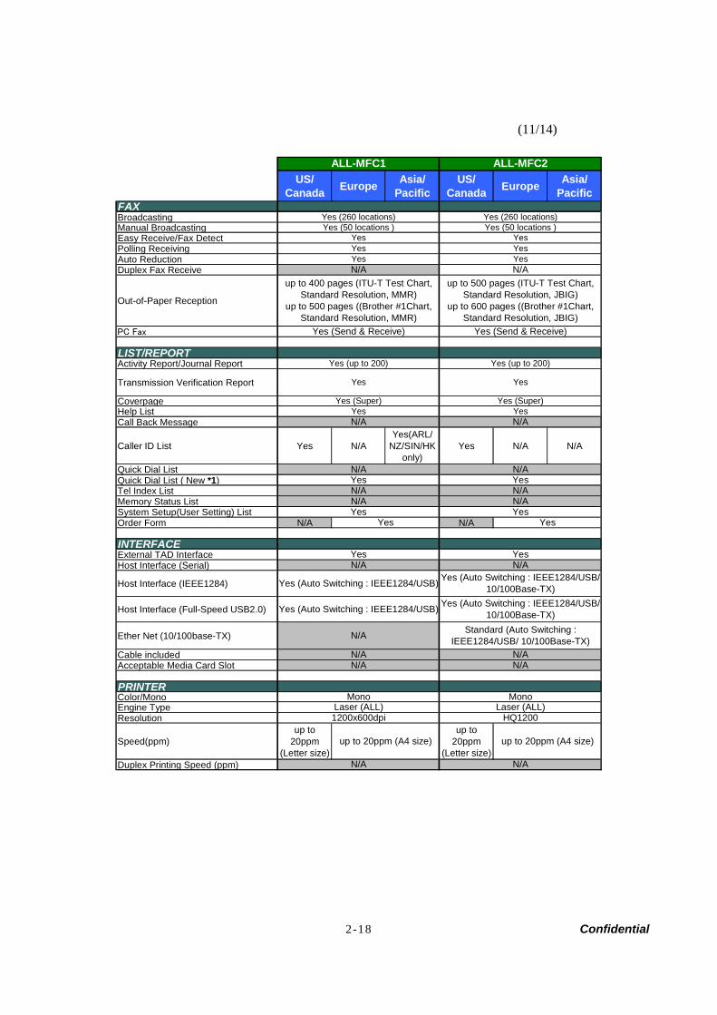
FAXModem SpeedBroadcastingManual BroadcastingEasy Receive/Fax DetectPolling Receiving Auto ReductionDuplex Fax Receive
Out-of-Paper Reception
PC Fax
LIST/REPORTActivity Report/Journal Report
Transmission Verification Report
CoverpageHelp ListCall Back Message
Caller ID List Yes N/AYes(ARL/
NZ/SIN/HKonly)
Yes N/A N/A
Quick Dial ListQuick Dial List ( New *1)Tel Index ListMemory Status List System Setup(User Setting) ListOrder Form N/A N/A
INTERFACEExternal TAD InterfaceHost Interface (Serial)
Host Interface (IEEE1284)
Host Interface (Full-Speed USB2.0)
Ether Net (10/100base-TX)
Cable includedAcceptable Media Card Slot
PRINTERColor/MonoEngine TypeResolution
Speed(ppm)up to
20ppm(Letter size)
up to20ppm
(Letter size)Duplex Printing Speed (ppm)
Yes (260 locations)
up to 400 pages (ITU-T Test Chart,Standard Resolution, MMR)
up to 500 pages ((Brother #1Chart,Standard Resolution, MMR)
Yes (50 locations )
YesYes
up to 500 pages (ITU-T Test Chart,Standard Resolution, JBIG)
up to 600 pages ((Brother #1Chart,Standard Resolution, JBIG)
Yes
Yes
Yes (Auto Switching : IEEE1284/USB)
Yes (Auto Switching : IEEE1284/USB)
N/A
YesN/AYes
Yes (Send & Receive)
Yes (260 locations)Yes (50 locations )
YesYes
Yes (up to 200)
Yes
N/A
N/A
N/AYesN/A N/A
N/A
Yes
N/A
Mono
1200x600dpi
Yes (Super)
N/AYes
N/A
N/A
Yes (Super)Yes
Yes
N/A
N/A
HQ1200Laser (ALL)
up to 20ppm (A4 size)
Yes (Send & Receive)
N/A
Laser (ALL)
Yes
Mono
Yes (up to 200)
YesYes
Yes
N/A
Standard (Auto Switching :IEEE1284/USB/ 10/100Base-TX)
N/A
ALL-MFC2
N/A
N/A
ALL-MFC1
Yes (Auto Switching : IEEE1284/USB/10/100Base-TX)
Yes (Auto Switching : IEEE1284/USB/10/100Base-TX)
up to 20ppm (A4 size)
2-19 Confidential
(12/14)
US/Canada Europe Asia/
PacificUS/
Canada Europe Asia/Pacific
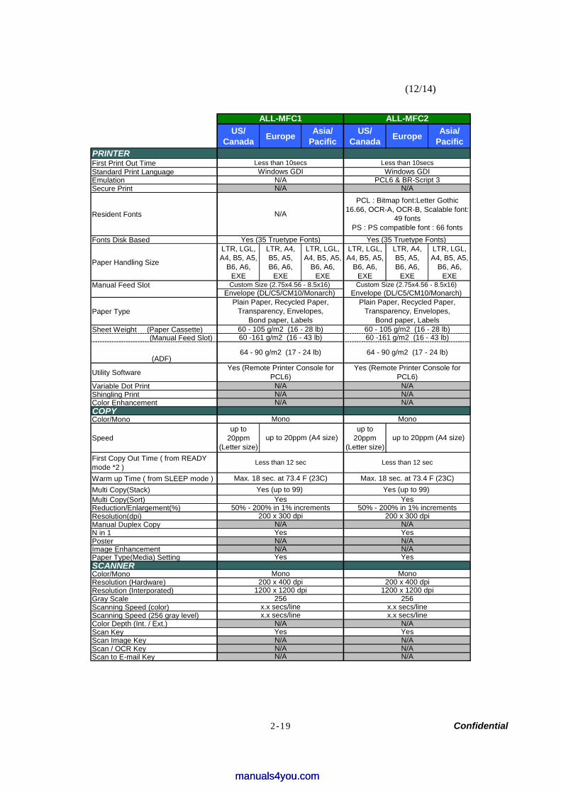
PRINTERFirst Print Out TimeStandard Print LanguageEmulationSecure Print
Resident Fonts
Fonts Disk Based
Paper Handling Size
LTR, LGL,A4, B5, A5,
B6, A6,EXE
LTR, A4,B5, A5,B6, A6,
EXE
LTR, LGL,A4, B5, A5,
B6, A6,EXE
LTR, LGL,A4, B5, A5,
B6, A6,EXE
LTR, A4,B5, A5,B6, A6,
EXE
LTR, LGL,A4, B5, A5,
B6, A6,EXE
Manual Feed Slot
Paper Type
Sheet Weight (Paper Cassette) (Manual Feed Slot)
(ADF)
Utility Software
Variable Dot PrintShingling PrintColor EnhancementCOPYColor/Mono
Speedup to
20ppm(Letter size)
up to20ppm
(Letter size)First Copy Out Time ( from READYmode *2 )Warm up Time ( from SLEEP mode )Multi Copy(Stack)Multi Copy(Sort)Reduction/Enlargement(%)Resolution(dpi)Manual Duplex Copy N in 1PosterImage EnhancementPaper Type(Media) Setting SCANNERColor/MonoResolution (Hardware)Resolution (Interporated)Gray ScaleScanning Speed (color)Scanning Speed (256 gray level)Color Depth (Int. / Ext.)Scan KeyScan Image KeyScan / OCR KeyScan to E-mail Key N/A
N/A
50% - 200% in 1% increments
Less than 10secs Less than 10secs
N/A
50% - 200% in 1% increments
Yes (Remote Printer Console forPCL6)
Less than 12 sec
N/A
200 x 300 dpi
x.x secs/linex.x secs/line
N/A
N/A
N/A
N/A
N/AN/A
Mono
ALL-MFC1
Yes
Mono
64 - 90 g/m2 (17 - 24 lb)
PCL : Bitmap font:Letter Gothic16.66, OCR-A, OCR-B, Scalable font:
49 fontsPS : PS compatible font : 66 fonts
60 - 105 g/m2 (16 - 28 lb)60 -161 g/m2 (16 - 43 lb)
ALL-MFC2
Windows GDIWindows GDI
64 - 90 g/m2 (17 - 24 lb)
Yes (Remote Printer Console forPCL6)
Yes
N/A
x.x secs/linex.x secs/line
N/A
Yes (up to 99)
Mono
Yes
200 x 400 dpi
N/A
N/A
YesYes
2561200 x 1200 dpi
256
YesN/A
1200 x 1200 dpi
Max. 18 sec. at 73.4 F (23C)
Less than 12 sec
N/AN/A
200 x 300 dpi
Mono
N/A
N/A
Yes (35 Truetype Fonts)
200 x 400 dpi
60 - 105 g/m2 (16 - 28 lb)60 -161 g/m2 (16 - 43 lb)
Plain Paper, Recycled Paper,Transparency, Envelopes,
Bond paper, Labels
up to 20ppm (A4 size)
Yes
N/A
N/A
Yes (35 Truetype Fonts)
Custom Size (2.75x4.56 - 8.5x16) Envelope (DL/C5/CM10/Monarch)
N/APCL6 & BR-Script 3
Yes
N/AN/A
Max. 18 sec. at 73.4 F (23C)
up to 20ppm (A4 size)
Yes (up to 99)
Custom Size (2.75x4.56 - 8.5x16)
Plain Paper, Recycled Paper,Transparency, Envelopes,
Bond paper, Labels
Envelope (DL/C5/CM10/Monarch)
manuals4you.commanuals4you.com
2-20 Confidential
(13/14)
US/Canada Europe Asia/
PacificUS/
Canada Europe Asia/Pacific
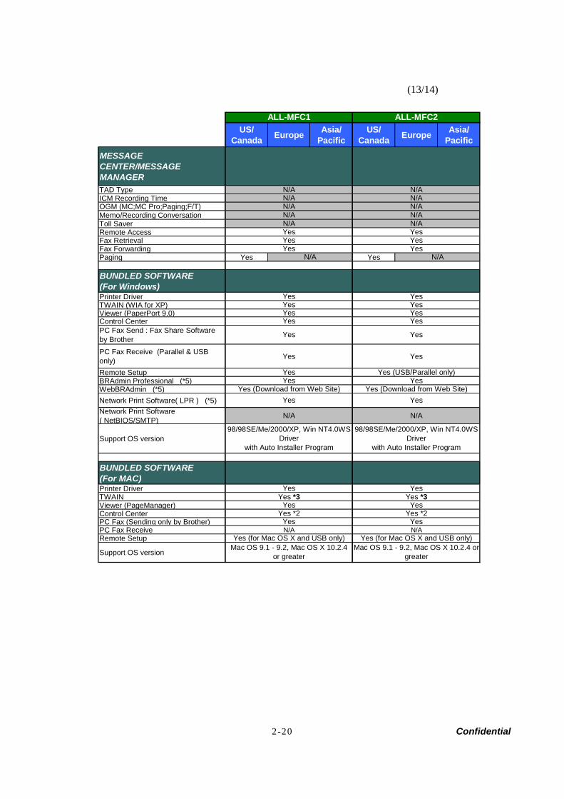
MESSAGECENTER/MESSAGEMANAGERTAD TypeICM Recording TimeOGM (MC;MC Pro;Paging;F/T)Memo/Recording ConversationToll SaverRemote AccessFax RetrievalFax ForwardingPaging Yes Yes
BUNDLED SOFTWARE(For Windows)Printer DriverTWAIN (WIA for XP)Viewer (PaperPort 9.0)Control CenterPC Fax Send : Fax Share Softwareby BrotherPC Fax Receive (Parallel & USBonly) Yes Yes
Remote SetupBRAdmin Professional (*5)WebBRAdmin (*5)Network Print Software( LPR ) (*5)Network Print Software( NetBIOS/SMTP)
Support OS version
BUNDLED SOFTWARE(For MAC)Printer DriverTWAINViewer (PageManager) Control Center PC Fax (Sending only by Brother)PC Fax Receive N/A N/ARemote Setup
Support OS version
Yes (USB/Parallel only)
Yes
N/A
N/A
Yes
Yes
N/A
YesYes
YesYesYes
Yes
Yes
N/A
Yes
Yes
Yes
N/AN/A
ALL-MFC1 ALL-MFC2
N/AN/A
Yes
N/A
Yes (for Mac OS X and USB only)
Yes
Yes
YesYes *3
N/AN/A
Yes
Yes
Yes (for Mac OS X and USB only)
N/A
N/A
Yes *2
Yes (Download from Web Site)
Yes
98/98SE/Me/2000/XP, Win NT4.0WSDriver
with Auto Installer Program
N/A
Yes
Yes
Mac OS 9.1 - 9.2, Mac OS X 10.2.4or greater
Mac OS 9.1 - 9.2, Mac OS X 10.2.4 orgreater
Yes *2
Yes
98/98SE/Me/2000/XP, Win NT4.0WSDriver
with Auto Installer Program
Yes
Yes (Download from Web Site)Yes
Yes *3
Yes
Yes
2-21 Confidential
(14/14)
US/Canada Europe Asia/
PacificUS/
Canada Europe Asia/Pacific
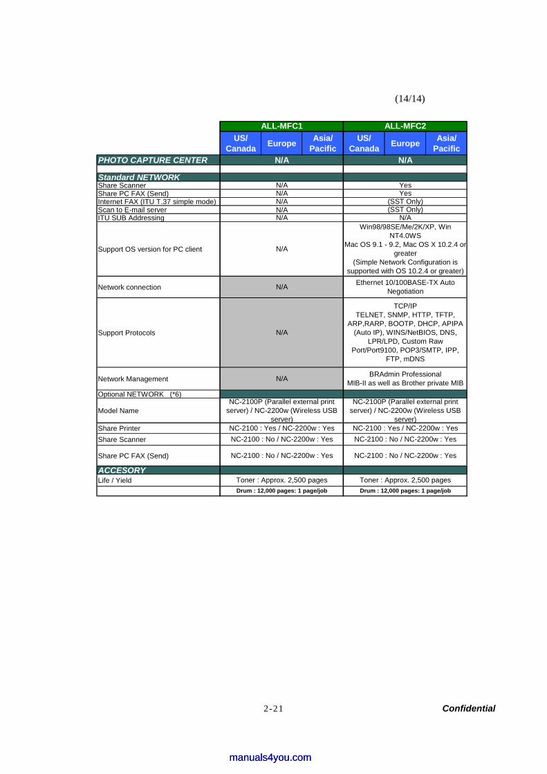
PHOTO CAPTURE CENTER N/A N/A
Standard NETWORKShare ScannerShare PC FAX (Send)Internet FAX (ITU T.37 simple mode)Scan to E-mail server N/AITU SUB Addressing
Support OS version for PC client
Network connection
Support Protocols
Network Management
Optional NETWORK (*6)
Model Name
Share PrinterShare Scanner
Share PC FAX (Send)
ACCESORYLife / Yield
N/A
N/A
N/A
N/A
ALL-MFC1
N/A
Toner : Approx. 2,500 pages
ALL-MFC2
N/A
Win98/98SE/Me/2K/XP, WinNT4.0WS
Mac OS 9.1 - 9.2, Mac OS X 10.2.4 orgreater
(Simple Network Configuration issupported with OS 10.2.4 or greater)
(SST Only)
Ethernet 10/100BASE-TX AutoNegotiation
Drum : 12,000 pages: 1 page/job
NC-2100P (Parallel external printserver) / NC-2200w (Wireless USB
server)
NC-2100 : No / NC-2200w : YesNC-2100 : Yes / NC-2200w : Yes
NC-2100 : No / NC-2200w : Yes
Drum : 12,000 pages: 1 page/job
TCP/IPTELNET, SNMP, HTTP, TFTP,
ARP,RARP, BOOTP, DHCP, APIPA(Auto IP), WINS/NetBIOS, DNS,
LPR/LPD, Custom RawPort/Port9100, POP3/SMTP, IPP,
FTP, mDNS
BRAdmin ProfessionalMIB-II as well as Brother private MIB
Toner : Approx. 2,500 pages
NC-2100 : Yes / NC-2200w : YesNC-2100 : No / NC-2200w : Yes
NC-2100P (Parallel external printserver) / NC-2200w (Wireless USB
server)
NC-2100 : No / NC-2200w : Yes
Yes
N/A
N/AN/A
(SST Only)Yes
manuals4you.commanuals4you.com

Confidential
CHAPTER 3THEORY OF OPERATION
Confidential
CHAPTER 3 THEORY OF OPERATION
This chapter gives an overview of the scanning and printing mechanisms as well as the sensors, actuators, and control electronics. It aids in understanding the basic principles of operation as well as locating defects for troubleshooting.
CONTENTS
3.1 OVERVIEW ......................................................................................................................3-1
3.2 MECHANICAL COMPONENTS.......................................................................................3-2
3.2.1 Scanner Mechanism ............................................................................................3-3
3.2.2 Document Feeding and Ejecting Mechanism.......................................................3-3
3.2.3 Scanner ................................................................................................................3-3
3.2.4 Printing Mechanism..............................................................................................3-4
3.2.4.1 Paper supply ................................................................................................3-4
3.2.4.2 Push-up function of paper tray.....................................................................3-6
3.2.4.3 Paper registration.........................................................................................3-8
3.2.4.4 Paper eject ...................................................................................................3-9
3.2.4.5 Drum unit......................................................................................................3-9
3.2.4.6 Toner cartridge...........................................................................................3-10
3.2.4.7 Print process ..............................................................................................3-13
3.2.5 Sensors and Actuators .......................................................................................3-16
3.3 CONTROL ELECTRONICS...........................................................................................3-17
3.3.1 Components .......................................................................................................3-17
manuals4you.commanuals4you.com
Confidential 3 - 1
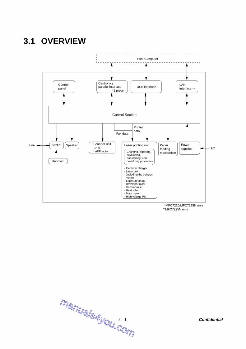
3.1 OVERVIEW
Control Section
Centronicsparallel interface USB interface
Host Computer
Controlpanel
LANinterface
Printerdata
Fax data
Powersupplies AC
Paperfeedingmechanism
Laser printing unit
*MFC7220/MFC7225N only
Charging, exposing,developing,transferring, andheat-fixing processes
- Electrical charger- Laser unit (including the polygon motor)- Exposure drum- Developer roller- Transfer roller- Heat roller- Main motor
Scanner unitNCU*Line Speak
Handset
er- CIS - ADF motor
- High voltage PS
**MFC7225N only
***1 piece
manuals4you.com
manuals4you.com
Confidential 3 - 2
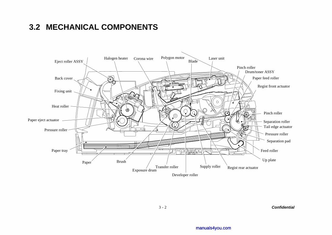
3.2 MECHANICAL COMPONENTS
Pinch rollerDrum/toner ASSY
Paper feed roller
Regist front actuator
Pinch roller
Separation roller Tail edge actuator
Pressure roller
Separation pad
Feed roller
Up plate
Regist rear actuator Supply roller
Developer roller
Transfer rollerExposure drum
Brush Paper
Paper tray
Pressure roller
Heat roller
Fixing unit
Back cover
Eject roller ASSY Halogen heater Corona wire Polygon motor
BladeLaser unit
Paper eject actuator
manuals4you.commanuals4you.com
Confidential 3 - 3
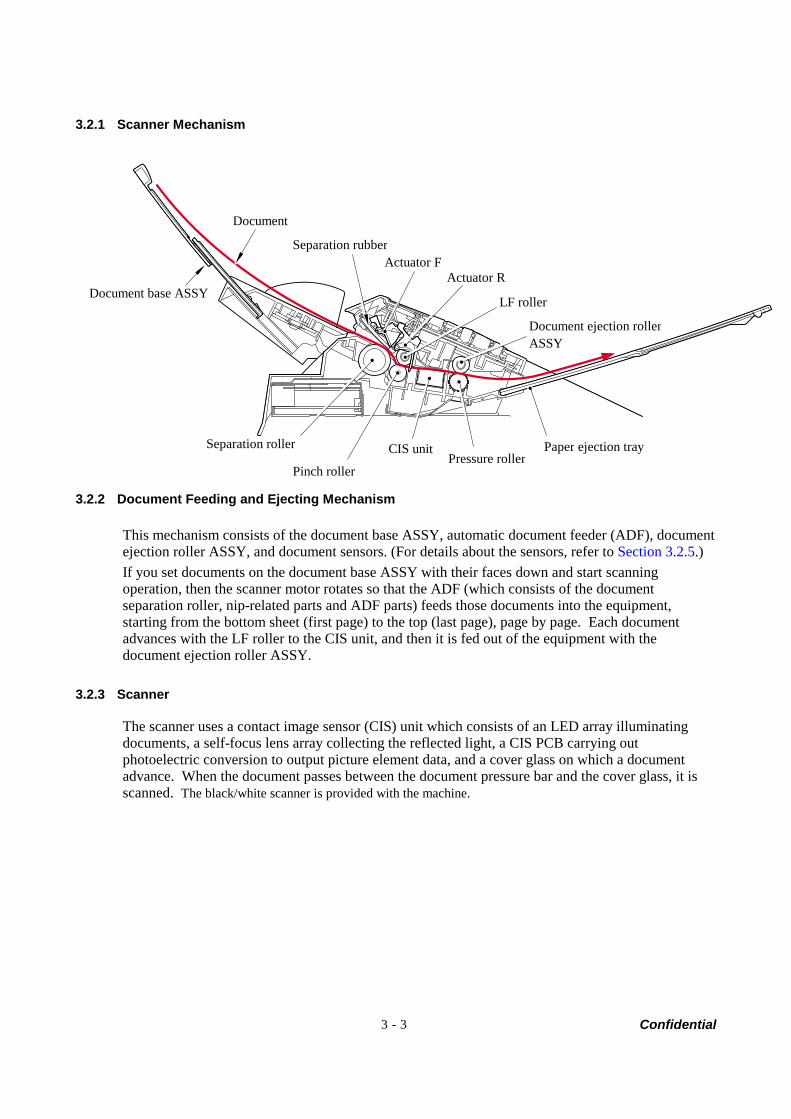
3.2.1 Scanner Mechanism
3.2.2 Document Feeding and Ejecting Mechanism
This mechanism consists of the document base ASSY, automatic document feeder (ADF), document ejection roller ASSY, and document sensors. (For details about the sensors, refer to Section 3.2.5.) If you set documents on the document base ASSY with their faces down and start scanning operation, then the scanner motor rotates so that the ADF (which consists of the document separation roller, nip-related parts and ADF parts) feeds those documents into the equipment, starting from the bottom sheet (first page) to the top (last page), page by page. Each document advances with the LF roller to the CIS unit, and then it is fed out of the equipment with the document ejection roller ASSY.
3.2.3 Scanner
The scanner uses a contact image sensor (CIS) unit which consists of an LED array illuminating documents, a self-focus lens array collecting the reflected light, a CIS PCB carrying out photoelectric conversion to output picture element data, and a cover glass on which a document advance. When the document passes between the document pressure bar and the cover glass, it is scanned. The black/white scanner is provided with the machine.
Document
Document base ASSY
Separation rubber
Pinch roller
CIS unitPressure roller
Paper ejection tray
Document ejection rollerASSY
Actuator F Actuator R
LF roller
Separation roller
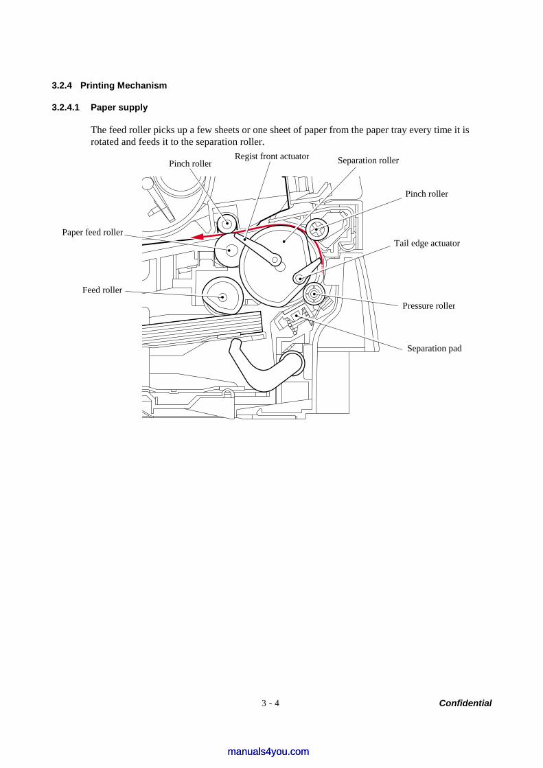
Confidential 3 - 4
3.2.4 Printing Mechanism
3.2.4.1 Paper supply
The feed roller picks up a few sheets or one sheet of paper from the paper tray every time it is rotated and feeds it to the separation roller.
Separation pad
Pressure roller
Tail edge actuator
Pinch roller
Regist front actuatorPinch roller
Paper feed roller
Feed roller
Separation roller
manuals4you.commanuals4you.com
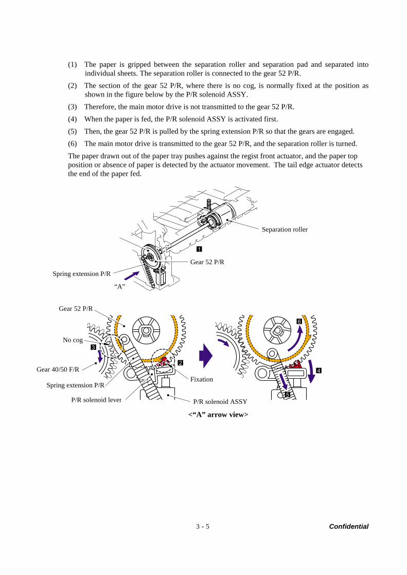
Confidential 3 - 5
(1) The paper is gripped between the separation roller and separation pad and separated into individual sheets. The separation roller is connected to the gear 52 P/R.
(2) The section of the gear 52 P/R, where there is no cog, is normally fixed at the position as shown in the figure below by the P/R solenoid ASSY.
(3) Therefore, the main motor drive is not transmitted to the gear 52 P/R. (4) When the paper is fed, the P/R solenoid ASSY is activated first. (5) Then, the gear 52 P/R is pulled by the spring extension P/R so that the gears are engaged. (6) The main motor drive is transmitted to the gear 52 P/R, and the separation roller is turned. The paper drawn out of the paper tray pushes against the regist front actuator, and the paper top position or absence of paper is detected by the actuator movement. The tail edge actuator detects the end of the paper fed.
3
2
1
5
4
6
<“A” arrow view>
Separation roller
Gear 52 P/R
Spring extension P/R
“A”
Gear 52 P/R
No cog
Gear 40/50 F/R
Spring extension P/R
P/R solenoid lever
Fixation
P/R solenoid ASSY
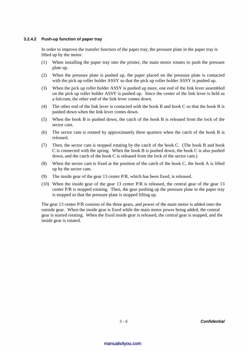
Confidential 3 - 6
3.2.4.2 Push-up function of paper tray
In order to improve the transfer function of the paper tray, the pressure plate in the paper tray is lifted up by the motor. (1) When installing the paper tray into the printer, the main motor rotates to push the pressure
plate up. (2) When the pressure plate is pushed up, the paper placed on the pressure plate is contacted
with the pick up roller holder ASSY so that the pick up roller holder ASSY is pushed up. (3) When the pick up roller holder ASSY is pushed up more, one end of the link lever assembled
on the pick up roller holder ASSY is pushed up. Since the center of the link lever is held as a fulcrum, the other end of the link lever comes down.
(4) The other end of the link lever is contacted with the hook B and hook C so that the hook B is pushed down when the link lever comes down.
(5) When the hook B is pushed down, the catch of the hook B is released from the lock of the sector cam.
(6) The sector cam is rotated by approximately three quarters when the catch of the hook B is released.
(7) Then, the sector cam is stopped rotating by the catch of the hook C. (The hook B and hook C is connected with the spring. When the hook B is pushed down, the hook C is also pushed down, and the catch of the hook C is released from the lock of the sector cam.)
(8) When the sector cam is fixed at the position of the catch of the hook C, the hook A is lifted up by the sector cam.
(9) The inside gear of the gear 13 center P/R, which has been fixed, is released. (10) When the inside gear of the gear 13 center P/R is released, the central gear of the gear 13
center P/R is stopped rotating. Then, the gear pushing up the pressure plate in the paper tray is stopped so that the pressure plate is stopped lifting up.
The gear 13 center P/R consists of the three gears, and power of the main motor is added onto the outside gear. When the inside gear is fixed while the main motor power being added, the central gear is started rotating. When the fixed inside gear is released, the central gear is stopped, and the inside gear is rotated.
manuals4you.commanuals4you.com
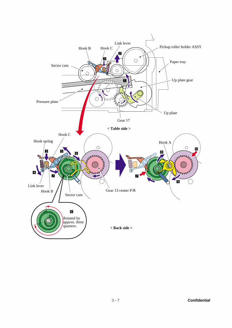
Confidential 3 - 7
Pickup roller holder ASSY
Paper tray
Up plate gear
Up plate
Gear 17
Pressure plate
Sector cam
Hook B Hook C Link lever
Hook A
Hook C
Hook spring
Gear 13 center P/RSector cam
Hook B Link lever
Rotated by approx. three quarters.
< Table side >
< Back side >
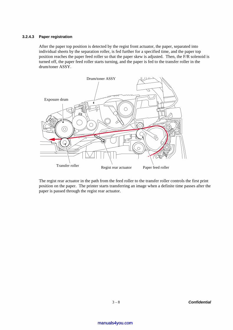
Confidential 3 - 8
3.2.4.3 Paper registration
After the paper top position is detected by the regist front actuator, the paper, separated into individual sheets by the separation roller, is fed further for a specified time, and the paper top position reaches the paper feed roller so that the paper skew is adjusted. Then, the F/R solenoid is turned off, the paper feed roller starts turning, and the paper is fed to the transfer roller in the drum/toner ASSY.
The regist rear actuator in the path from the feed roller to the transfer roller controls the first print position on the paper. The printer starts transferring an image when a definite time passes after the paper is passed through the regist rear actuator.
Drum/toner ASSY
Exposure drum
Paper feed roller Regist rear actuator Transfer roller
manuals4you.commanuals4you.com
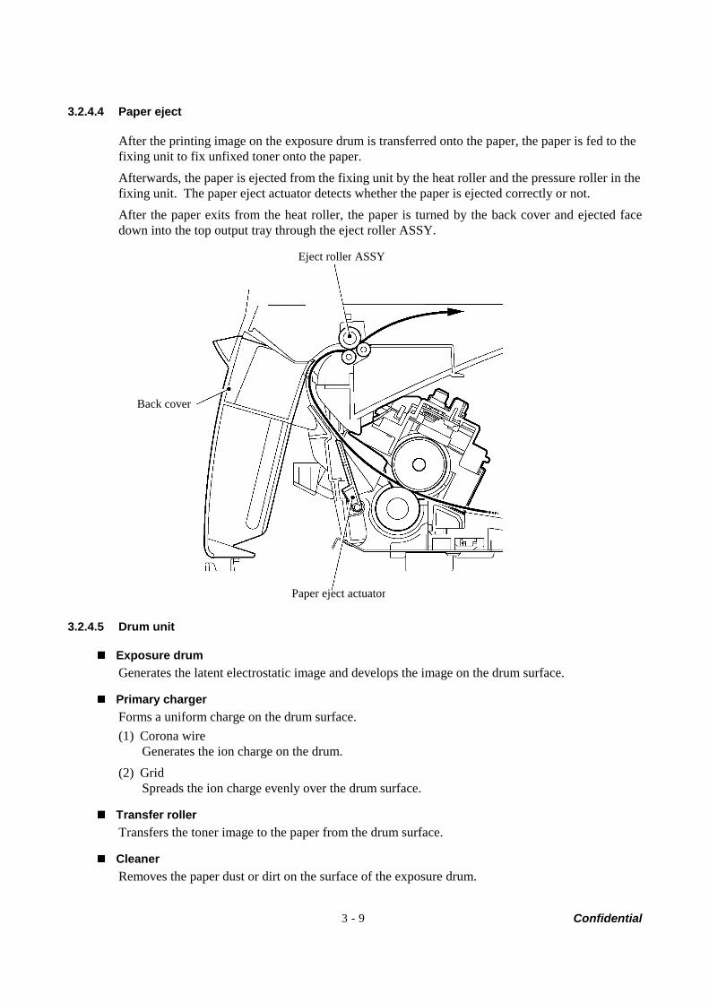
Confidential 3 - 9
3.2.4.4 Paper eject
After the printing image on the exposure drum is transferred onto the paper, the paper is fed to the fixing unit to fix unfixed toner onto the paper. Afterwards, the paper is ejected from the fixing unit by the heat roller and the pressure roller in the fixing unit. The paper eject actuator detects whether the paper is ejected correctly or not. After the paper exits from the heat roller, the paper is turned by the back cover and ejected face down into the top output tray through the eject roller ASSY.
3.2.4.5 Drum unit
Exposure drum Generates the latent electrostatic image and develops the image on the drum surface.
Primary charger Forms a uniform charge on the drum surface. (1) Corona wire
Generates the ion charge on the drum. (2) Grid
Spreads the ion charge evenly over the drum surface.
Transfer roller Transfers the toner image to the paper from the drum surface.
Cleaner Removes the paper dust or dirt on the surface of the exposure drum.
Eject roller ASSY
Paper eject actuator
Back cover
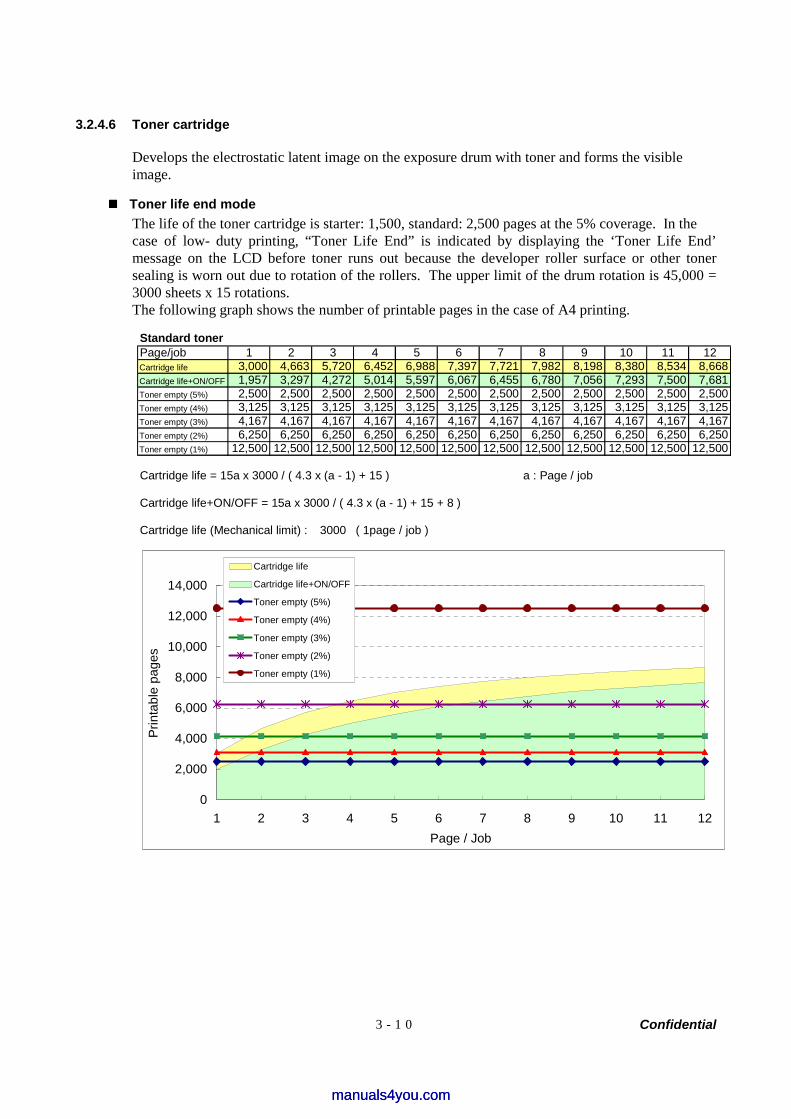
Confidential 3 - 1 0
3.2.4.6 Toner cartridge
Develops the electrostatic latent image on the exposure drum with toner and forms the visible image.
Toner life end mode The life of the toner cartridge is starter: 1,500, standard: 2,500 pages at the 5% coverage. In the case of low- duty printing, “Toner Life End” is indicated by displaying the ‘Toner Life End’ message on the LCD before toner runs out because the developer roller surface or other toner sealing is worn out due to rotation of the rollers. The upper limit of the drum rotation is 45,000 = 3000 sheets x 15 rotations. The following graph shows the number of printable pages in the case of A4 printing.
Standard tonerPage/job 1 2 3 4 5 6 7 8 9 10 11 12Cartridge life 3,000 4,663 5,720 6,452 6,988 7,397 7,721 7,982 8,198 8,380 8,534 8,668Cartridge life+ON/OFF 1,957 3,297 4,272 5,014 5,597 6,067 6,455 6,780 7,056 7,293 7,500 7,681Toner empty (5%) 2,500 2,500 2,500 2,500 2,500 2,500 2,500 2,500 2,500 2,500 2,500 2,500Toner empty (4%) 3,125 3,125 3,125 3,125 3,125 3,125 3,125 3,125 3,125 3,125 3,125 3,125Toner empty (3%) 4,167 4,167 4,167 4,167 4,167 4,167 4,167 4,167 4,167 4,167 4,167 4,167Toner empty (2%) 6,250 6,250 6,250 6,250 6,250 6,250 6,250 6,250 6,250 6,250 6,250 6,250Toner empty (1%) 12,500 12,500 12,500 12,500 12,500 12,500 12,500 12,500 12,500 12,500 12,500 12,500
Cartridge life = 15a x 3000 / ( 4.3 x (a - 1) + 15 ) a : Page / job
Cartridge life+ON/OFF = 15a x 3000 / ( 4.3 x (a - 1) + 15 + 8 )
Cartridge life (Mechanical limit) : 3000 ( 1page / job )
0
2,000
4,000
6,000
8,000
10,000
12,000
14,000
1 2 3 4 5 6 7 8 9 10 11 12Page / Job
Prin
tabl
e pa
ges
Cartridge life
Cartridge life+ON/OFF
Toner empty (5%)
Toner empty (4%)
Toner empty (3%)
Toner empty (2%)
Toner empty (1%)
manuals4you.commanuals4you.com
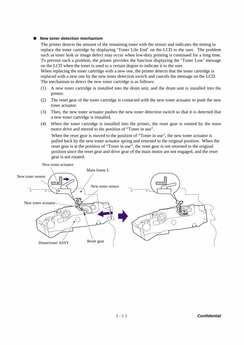
Confidential 3 - 1 1
New toner detection mechanism The printer detects the amount of the remaining toner with the sensor and indicates the timing to replace the toner cartridge by displaying ‘Toner Life End’ on the LCD to the user. The problem such as toner leak or image defect may occur when low-duty printing is continued for a long time. To prevent such a problem, the printer provides the function displaying the ‘Toner Low’ message on the LCD when the toner is used to a certain degree to indicate it to the user. When replacing the toner cartridge with a new one, the printer detects that the toner cartridge is replaced with a new one by the new toner detection switch and cancels the message on the LCD. The mechanism to detect the new toner cartridge is as follows: (1) A new toner cartridge is installed into the drum unit, and the drum unit is installed into the
printer. (2) The reset gear of the toner cartridge is contacted with the new toner actuator to push the new
toner actuator. (3) Then, the new toner actuator pushes the new toner detection switch so that it is detected that
a new toner cartridge is installed. (4) When the toner cartridge is installed into the printer, the reset gear is rotated by the main
motor drive and moved to the position of “Toner in use”. When the reset gear is moved to the position of “Toner in use”, the new toner actuator is pulled back by the new toner actuator spring and returned to the original position. When the reset gear is at the position of “Toner in use”, the reset gear is not returned to the original position since the reset gear and drive gear of the main motor are not engaged, and the reset gear is not rotated.
New toner sensor
Main frame LNew toner actuator
New toner sensor
New toner actuator
Drum/toner ASSY Reset gear
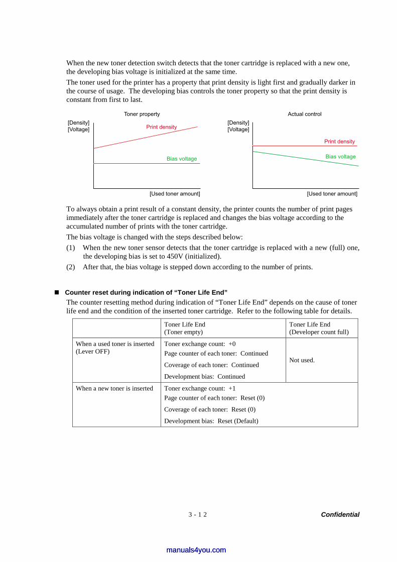
Confidential 3 - 1 2
When the new toner detection switch detects that the toner cartridge is replaced with a new one, the developing bias voltage is initialized at the same time. The toner used for the printer has a property that print density is light first and gradually darker in the course of usage. The developing bias controls the toner property so that the print density is constant from first to last.
Toner property Actual control
[Used toner amount] [Used toner amount]
Print density
Bias voltage Bias voltage
Print density
[Density][Voltage]
[Density][Voltage]
To always obtain a print result of a constant density, the printer counts the number of print pages immediately after the toner cartridge is replaced and changes the bias voltage according to the accumulated number of prints with the toner cartridge. The bias voltage is changed with the steps described below: (1) When the new toner sensor detects that the toner cartridge is replaced with a new (full) one,
the developing bias is set to 450V (initialized). (2) After that, the bias voltage is stepped down according to the number of prints.
Counter reset during indication of “Toner Life End” The counter resetting method during indication of “Toner Life End” depends on the cause of toner life end and the condition of the inserted toner cartridge. Refer to the following table for details.
Toner Life End (Toner empty)
Toner Life End (Developer count full)
When a used toner is inserted (Lever OFF)
Toner exchange count: +0 Page counter of each toner: Continued
Coverage of each toner: Continued
Development bias: Continued
Not used.
When a new toner is inserted Toner exchange count: +1 Page counter of each toner: Reset (0)
Coverage of each toner: Reset (0)
Development bias: Reset (Default)
manuals4you.commanuals4you.com
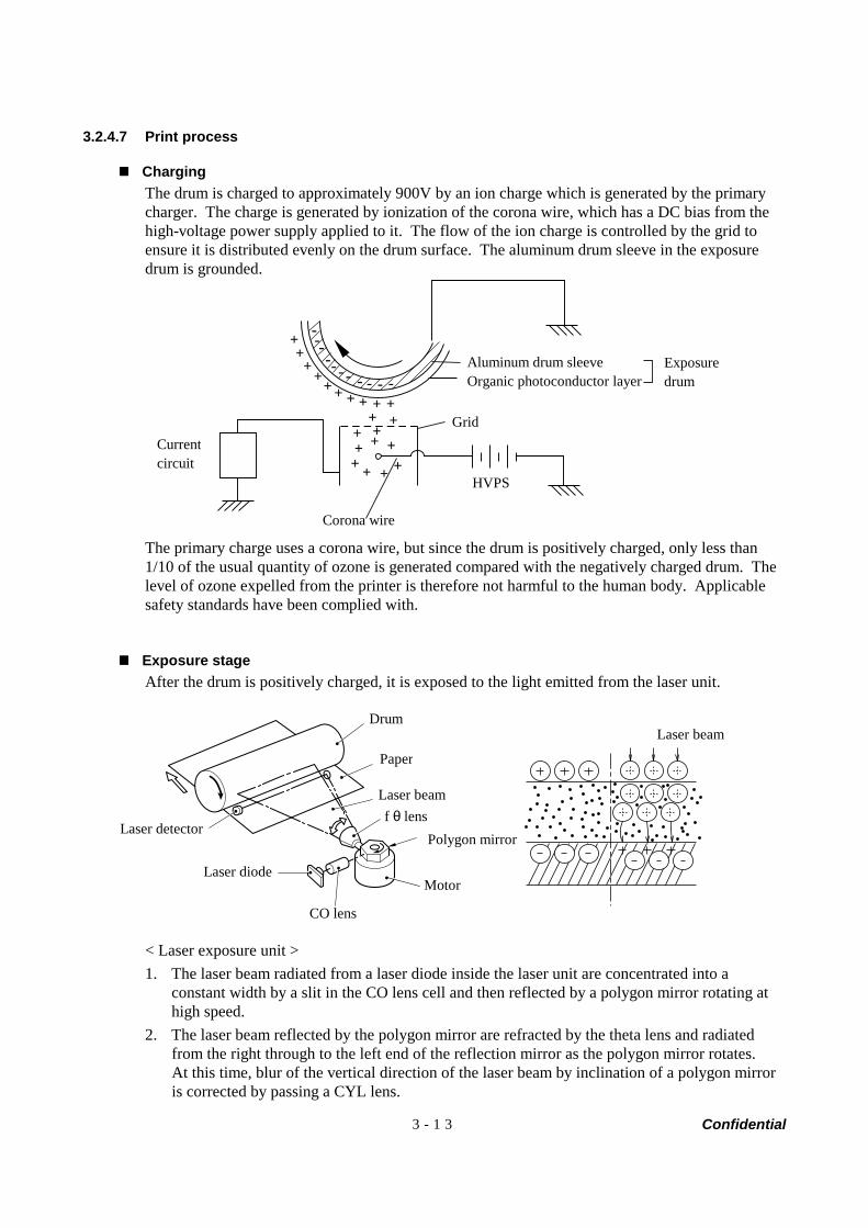
Confidential 3 - 1 3
3.2.4.7 Print process
Charging The drum is charged to approximately 900V by an ion charge which is generated by the primary charger. The charge is generated by ionization of the corona wire, which has a DC bias from the high-voltage power supply applied to it. The flow of the ion charge is controlled by the grid to ensure it is distributed evenly on the drum surface. The aluminum drum sleeve in the exposure drum is grounded.
+++
++ + + + +
++
+++
+++
+ + ++
------- - - - -
The primary charge uses a corona wire, but since the drum is positively charged, only less than 1/10 of the usual quantity of ozone is generated compared with the negatively charged drum. The level of ozone expelled from the printer is therefore not harmful to the human body. Applicable safety standards have been complied with.
Exposure stage After the drum is positively charged, it is exposed to the light emitted from the laser unit.
< Laser exposure unit > 1. The laser beam radiated from a laser diode inside the laser unit are concentrated into a
constant width by a slit in the CO lens cell and then reflected by a polygon mirror rotating at high speed.
2. The laser beam reflected by the polygon mirror are refracted by the theta lens and radiated from the right through to the left end of the reflection mirror as the polygon mirror rotates. At this time, blur of the vertical direction of the laser beam by inclination of a polygon mirror is corrected by passing a CYL lens.
Exposuredrum
Aluminum drum sleeveOrganic photoconductor layer
Grid
Corona wire
HVPS
Current circuit
Polygon mirror
Drum
Paper
Laser beam f θ lens
Motor
CO lens
Laser diode
Laser detector
Laser beam
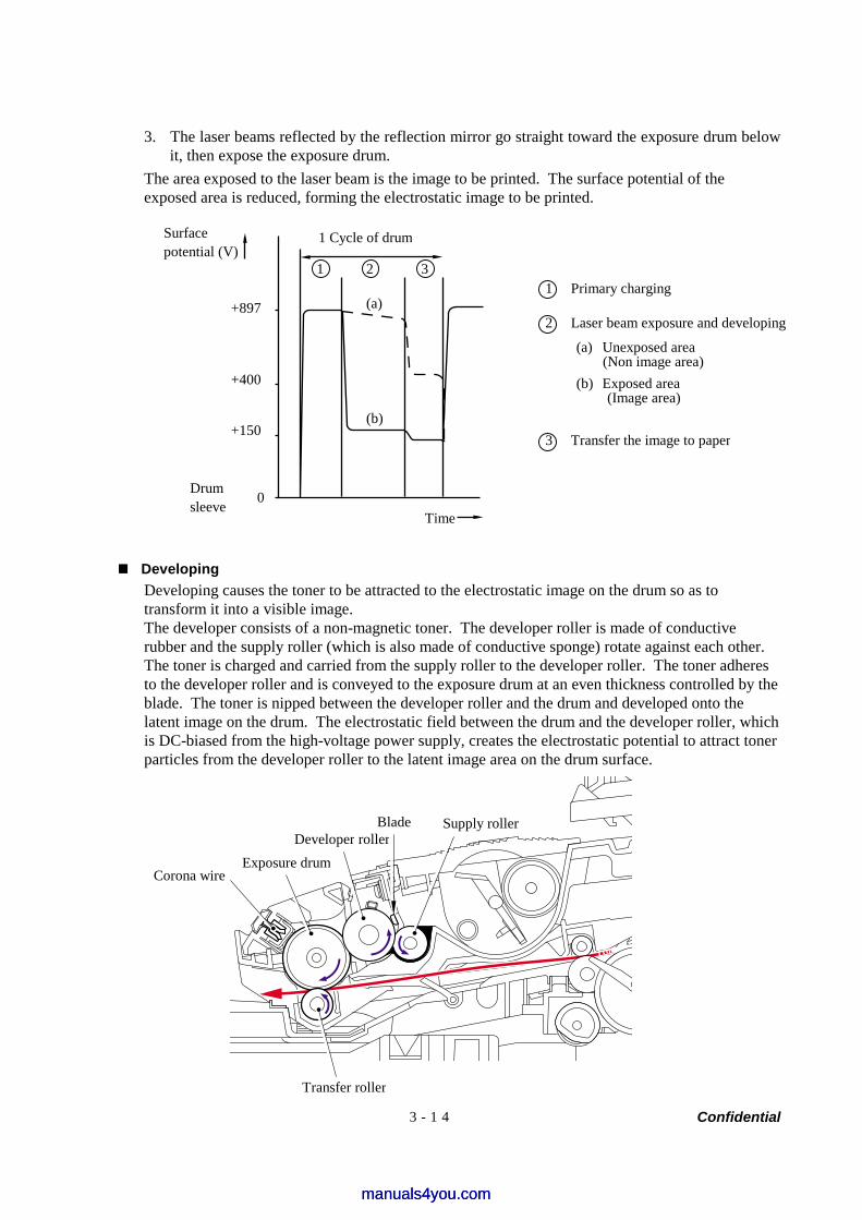
Confidential 3 - 1 4
3. The laser beams reflected by the reflection mirror go straight toward the exposure drum below it, then expose the exposure drum.
The area exposed to the laser beam is the image to be printed. The surface potential of the exposed area is reduced, forming the electrostatic image to be printed.
Developing Developing causes the toner to be attracted to the electrostatic image on the drum so as to transform it into a visible image. The developer consists of a non-magnetic toner. The developer roller is made of conductive rubber and the supply roller (which is also made of conductive sponge) rotate against each other. The toner is charged and carried from the supply roller to the developer roller. The toner adheres to the developer roller and is conveyed to the exposure drum at an even thickness controlled by the blade. The toner is nipped between the developer roller and the drum and developed onto the latent image on the drum. The electrostatic field between the drum and the developer roller, which is DC-biased from the high-voltage power supply, creates the electrostatic potential to attract toner particles from the developer roller to the latent image area on the drum surface.
1 Cycle of drum Surface potential (V)
+897
+400
+150
Drum sleeve 0
Time
1 2 3
(a)
(b)
1 Primary charging
2 Laser beam exposure and developing
3 Transfer the image to paper
(a) Unexposed area (Non image area)
(b) Exposed area (Image area)
Supply rollerBlade Developer roller
Exposure drum Corona wire
Transfer roller
manuals4you.commanuals4you.com
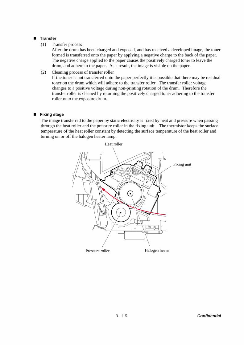
Confidential 3 - 1 5
Transfer (1) Transfer process
After the drum has been charged and exposed, and has received a developed image, the toner formed is transferred onto the paper by applying a negative charge to the back of the paper. The negative charge applied to the paper causes the positively charged toner to leave the drum, and adhere to the paper. As a result, the image is visible on the paper.
(2) Cleaning process of transfer roller If the toner is not transferred onto the paper perfectly it is possible that there may be residual toner on the drum which will adhere to the transfer roller. The transfer roller voltage changes to a positive voltage during non-printing rotation of the drum. Therefore the transfer roller is cleaned by returning the positively charged toner adhering to the transfer roller onto the exposure drum.
Fixing stage The image transferred to the paper by static electricity is fixed by heat and pressure when passing through the heat roller and the pressure roller in the fixing unit . The thermistor keeps the surface temperature of the heat roller constant by detecting the surface temperature of the heat roller and turning on or off the halogen heater lamp.
Heat roller
Fixing unit
Halogen heaterPressure roller
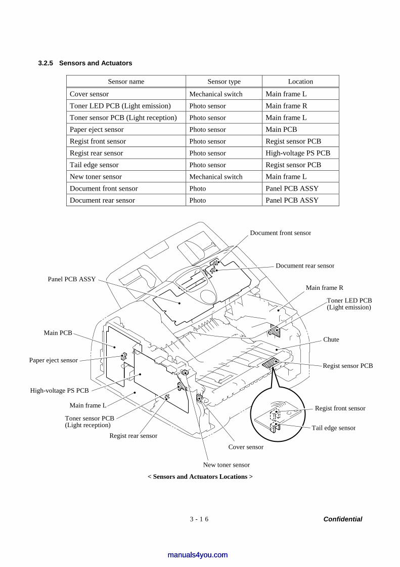
Confidential 3 - 1 6
3.2.5 Sensors and Actuators
Sensor name Sensor type Location
Cover sensor Mechanical switch Main frame L Toner LED PCB (Light emission) Photo sensor Main frame R Toner sensor PCB (Light reception) Photo sensor Main frame L Paper eject sensor Photo sensor Main PCB Regist front sensor Photo sensor Regist sensor PCB Regist rear sensor Photo sensor High-voltage PS PCB Tail edge sensor Photo sensor Regist sensor PCB New toner sensor Mechanical switch Main frame L Document front sensor Photo Panel PCB ASSY Document rear sensor Photo Panel PCB ASSY
< Sensors and Actuators Locations >
Document rear sensor
Main frame R
Toner LED PCB (Light emission)
Chute
Regist sensor PCB
Regist front sensor
Tail edge sensor
Cover sensor
New toner sensor
Regist rear sensor
Toner sensor PCB (Light reception)
Main frame L
Paper eject sensor
Main PCB
Panel PCB ASSY
High-voltage PS PCB
Document front sensor
manuals4you.commanuals4you.com
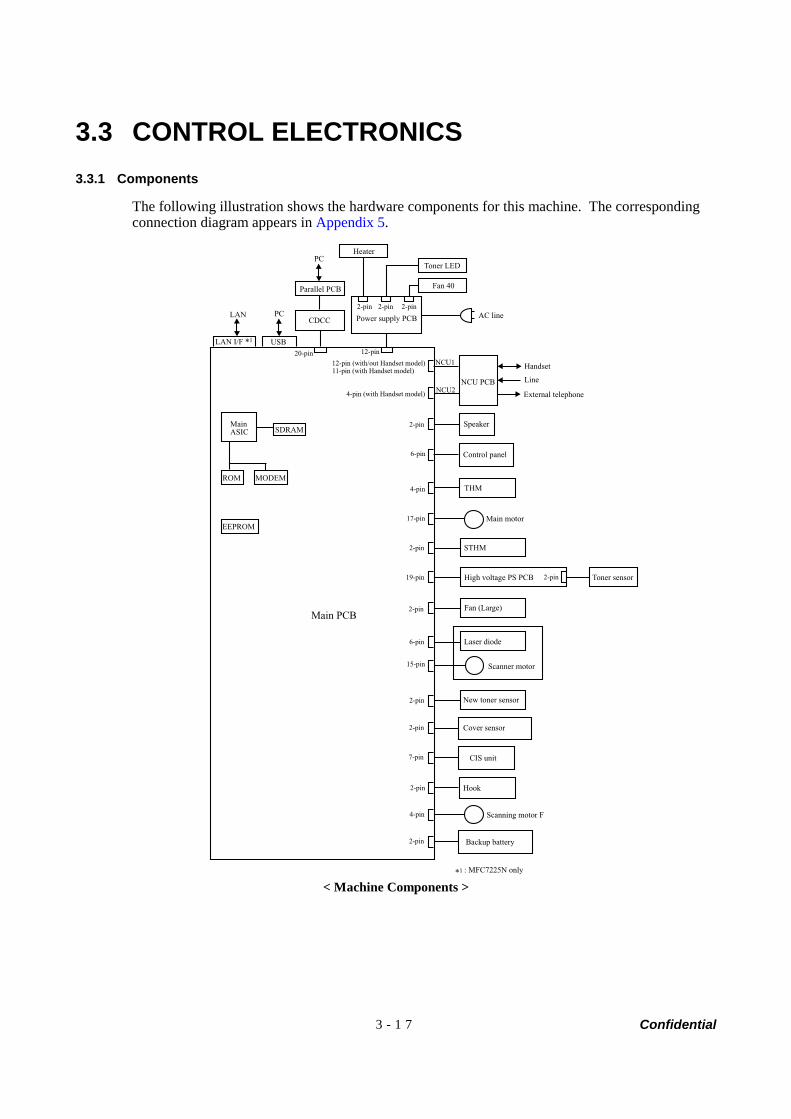
Confidential 3 - 1 7
3.3 CONTROL ELECTRONICS 3.3.1 Components
The following illustration shows the hardware components for this machine. The corresponding connection diagram appears in Appendix 5.
Main PCB
12-pin
ROM MODEM
SDRAM
NCU PCB
2-pin Speaker
Control panel6-pin
THM4-pin
17-pin
19-pin
7-pin CIS unit
2-pin Cover sensor
Handset
Line
External telephone
LAN PC
*1
High voltage PS PCB Toner sensor
EEPROM
2-pin
Scanning motor F
Hook
2-pin
2-pin
2-pin
2-pin Backup battery
LAN I/F USB
Power supply PCB AC line
MainASIC
4-pin (with Handset model)
12-pin (with/out Handset model)
4-pin
Main motor
Fan (Large)
New toner sensor
20-pin
2-pin 2-pin 2-pin
CDCC
6-pin
15-pin
Laser diode
Scanner motor
2-pin STHM
PC
Parallel PCB
Heater
Toner LED
Fan 40
*1
NCU1
NCU2
: MFC7225N only
11-pin (with Handset model)
< Machine Components >

Confidential
CHAPTER 4
TRANSFER OF DATA LEFT IN THE MACHINE TO BE SENT FOR REPAIR
manuals4you.commanuals4you.com

Confidential
CHAPTER 4 TRANSFER OF DATA LEFT IN THE MACHINE TO BE SENT FOR REPAIR
This chapter describes how to transfer data left in the machine to be sent for repair. The service personnel should instruct end users to follow the transfer procedure given in this chapter if the machine at the user site cannot print received data due to the printing mechanism defective. End users can transfer received data to another machine to prevent data loss.
CONTENTS
4.1 TRANSFERRING RECEIVED FAX DATA.......................................................................4-1
Confidential 4-1
4.1 TRANSFERRING RECEIVED FAX DATA When the machine at the user site requires to be repaired, unplugging the power cord from the wall socket for sending the machine for repair will lose received FAX data if unprinted and left in the machine. To prevent such data loss, the service personnel should instruct end users (e.g., by telephone) to transfer data to another facsimile machine using the procedure below.
NOTE: The number of files that can be transferred at a time is 99. To transfer 100 files or more, carry out the following procedure more than one time.
Operating Procedure
(1) Connect the machine to be repaired (that has received data in the memory) to the telephone line.
(2) Switch the machine on. (3) Press the Menu/Set, Start, Menu/Set, 0, 5 and 3 keys in this order to access user-accessible
functions of the maintenance mode. The "FAX TRANSFER" appears on the LCD.
(4) To check the number of received files, press the 1 key. The "1.NO. OF JOBS" appears on the LCD. Press the Menu/Set key, and the number of received files appears, just as "NO. OF. JOBS: 10."
(5) To transfer the activity report only, press the 2 key. The "2.ACTIVITY" appears. To transfer received files together with the activity report, press the 3 key. The "3.DOCUMENTS" appears. Note that if there is no received file, the "NO DOCUMENTS" appears.
(6) To transfer the communication list for the latest communication, press the 4 key. The "4.COM.LIST (NEW)" appears. To transfer the communication list for last three errors, press the 5 key. The "5.COM.LIST (ERR3)" appears.
(7) With the "2.ACTIVITY," "3.DOCUMENTS," "4.COM.LIST (NEW)," or "5.COM.LIST (ERR3)" being displayed, press the Menu/Set key. The "ENTER NO. &SET" appears.
(8) Enter the telephone number of the receiver machine and press the Menu/Set key again.
NOTE: Be sure to type the telephone number with the numerical keys. No one-touch dialing is allowed in this procedure. The machine displays the "ACCEPTED" for approx. two seconds and starts dialing to transfer data. No station ID will be attached. A cover page and end page as shown on the next page will be automatically attached, instead.
manuals4you.commanuals4you.com
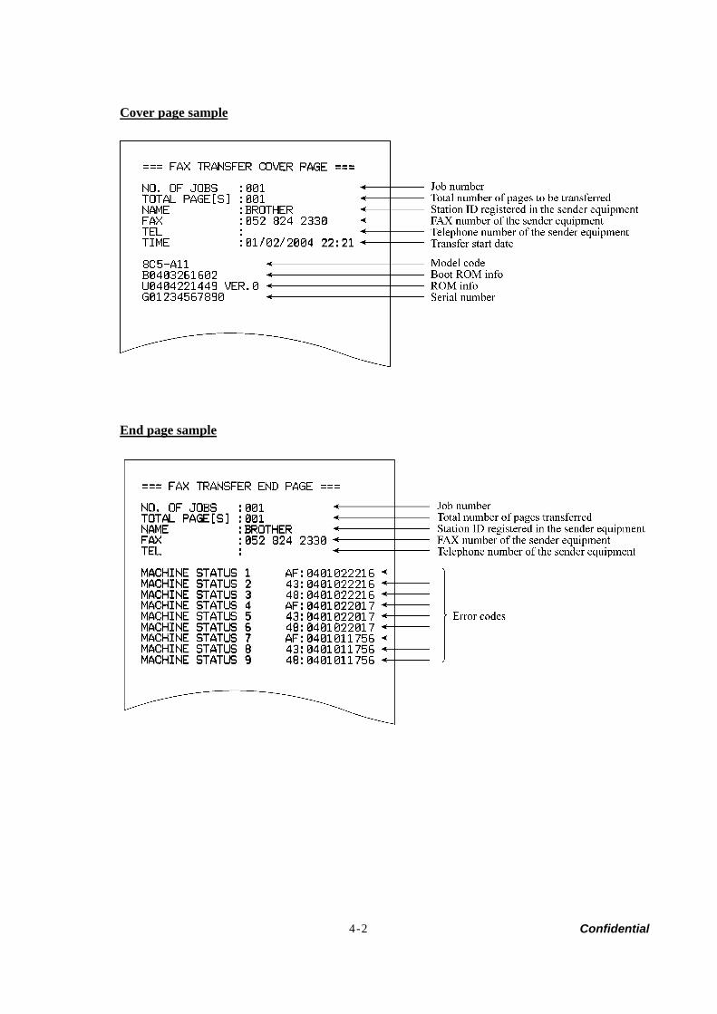
Confidential 4-2
Cover page sample
End page sample

Confidential
CHAPTER 5DISASSEMBLY/REASSEMBLY AND
LUBRICATION
manuals4you.commanuals4you.com

Confidential
CHAPTER 5 DISASSEMBLY/REASSEMBLY AND LUBRICATION
This chapter details procedures for disassembling and reassembling the machine together with related notes. The disassembly order flow provided enables you to see at a glance the quickest way to get to component(s) involved. At the start of a disassembly job, you check the disassembly order flow that guides you through a shortcut to the object components. This chapter also covers screw tightening torques and lubrication points to which the specified lubricants should be applied during reassembly jobs.
CONTENTS
5.1 DISASSEMBLY/REASSEMBLY .....................................................................................5-1
Safety Precautions........................................................................................................5-1
Tightening Torque.........................................................................................................5-2
Preparation ...................................................................................................................5-3
How to Access the Object Component .........................................................................5-3
Disassembly Flowchart .................................................................................................5-4
5.1.1 Paper Eject Tray ..................................................................................................5-5
5.1.2 Drum/Toner ASSY ...............................................................................................5-5
5.1.3 Paper Tray............................................................................................................5-6
5.1.4 Back Cover...........................................................................................................5-7
5.1.5 Rear Chute Cover ................................................................................................5-8
5.1.6 Document Base ASSY .........................................................................................5-9
5.1.7 Side Cover L.......................................................................................................5-10
5.1.8 Handset Holder ..................................................................................................5-11
5.1.9 Speaker ASSY ...................................................................................................5-12
5.1.10 Side Cover R/Link Stoper...................................................................................5-13
5.1.11 Panel Unit...........................................................................................................5-14
5.1.12 Hook PCB ASSY................................................................................................5-20
5.1.13 Top Cover...........................................................................................................5-21
5.1.14 NCU PCB ASSY ................................................................................................5-32
5.1.15 Paper Stopper L/S..............................................................................................5-34
5.1.16 Front Cover ........................................................................................................5-35
Confidential
5.1.17 Pickup Roller Holder ASSY................................................................................5-36
5.1.18 Fixing Unit ..........................................................................................................5-40
5.1.19 High-Voltage PS PCB ASSY..............................................................................5-45
5.1.20 Main PCB ...........................................................................................................5-46
5.1.21 PS PCB Unit/Fan 40 ..........................................................................................5-48
5.1.22 Laser Unit ...........................................................................................................5-52
5.1.23 Sub Chute ASSY................................................................................................5-53
5.1.24 Link Lever...........................................................................................................5-54
5.1.25 Tail Edge Actuator..............................................................................................5-55
5.1.26 Regist Front Actuator/Regist Front Spring .........................................................5-55
5.1.27 Regist Sensor PCB ASSY..................................................................................5-56
5.1.28 Regist Rear Actuator/Regist Rear Spring ..........................................................5-56
5.1.29 Fan Motor 60 Unit ..............................................................................................5-57
5.1.30 Toner LED PCB ASSY/LED Holder ...................................................................5-58
5.1.31 New Toner Actuator/New Toner Actuator Spring...............................................5-59
5.1.32 New Toner Sensor .............................................................................................5-59
5.1.33 Cover Sensor .....................................................................................................5-60
5.1.34 Toner Sensor PCB ASSY ..................................................................................5-60
5.1.35 Main Motor ASSY...............................................................................................5-61
5.1.36 Develop Joint......................................................................................................5-62
5.1.37 P/R Solenoid ASSY............................................................................................5-63
5.1.38 F/R Solenoid ASSY............................................................................................5-63
5.1.39 Main Frame L .....................................................................................................5-65
5.1.40 Main Frame R.....................................................................................................5-66
5.1.41 Harness Routing ................................................................................................5-67
5.2 LUBRICATION...............................................................................................................5-74
manuals4you.commanuals4you.com

Confidential
5-1
5.1 DISASSEMBLY/REASSEMBLY Safety Precautions
To prevent the creation of secondary problems by mishandling, observe the following precautions during maintenance work.
(1) Before starting disassembly/reassembly jobs, unplug the power cord and telephone line. In particular, when having access to the power supply inside the machine, make sure that the power cord is unplugged from the electrical outlet; when having access to the main PCB or NCU PCB, make sure that both the power cord and telephone line are unplugged from the machine.
(2) Be careful not to lose screws, washers, or other parts removed for parts replacement.
(3) When using soldering irons and other heat-generating tools, take care not to damage the resin parts such as wires, PCBs, and covers.
(4) Static electricity charged in your body may damage electronic parts. Before handling the PCBs, touch a metal portion of the machine to discharge static electricity charged in your body. When transporting PCBs, be sure to wrap them in conductive sheets such as aluminum foil.
(5) Be sure to reinsert self-tapping screws correctly, if removed.
(6) Tighten screws to the torque values listed on the next page.
(7) When connecting or disconnecting cable connectors, hold the connector bodies not the wires. If the connector has a lock, always slide the connector lock to unlock it.
(8) Before reassembly, apply the specified lubricant to the specified points. (Refer to Section 5.2 in this chapter.)
(9) After repairs, check not only the repaired portion but also that the connectors and other related portions function properly before operation checks.
(10) After you use the machine, some internal parts are extremely HOT! To prevent injuries, be careful not to put your fingers in the areas shown in the illustration.
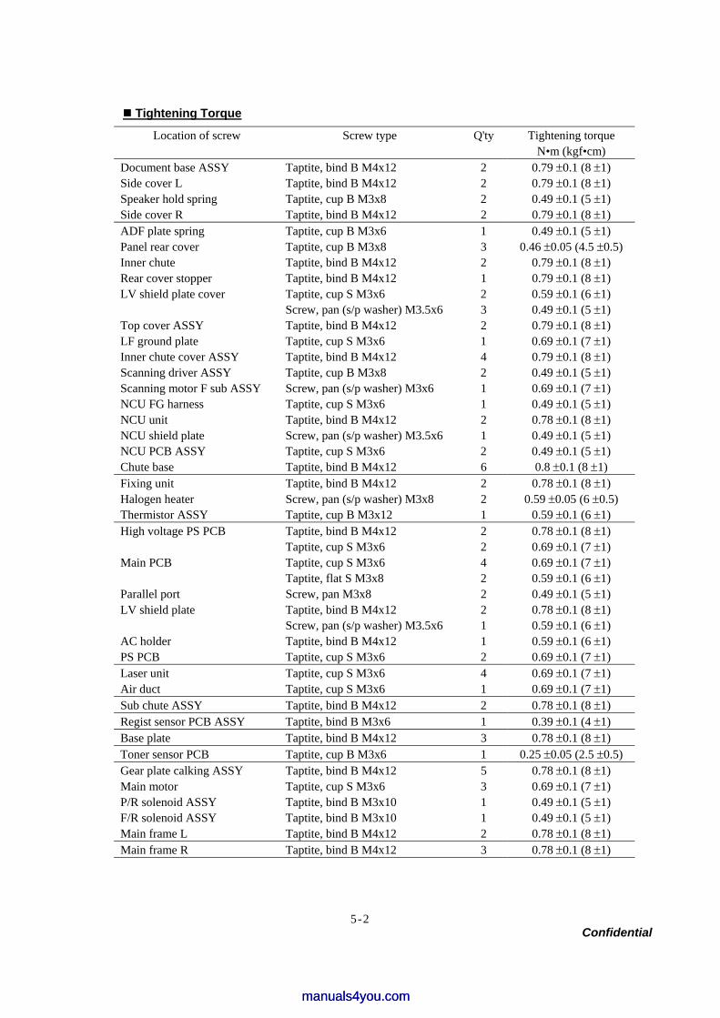
Confidential
5-2
Tightening Torque
Location of screw Screw type Q'ty Tightening torque N•m (kgf•cm)
Document base ASSY Side cover L Speaker hold spring
Taptite, bind B M4x12 Taptite, bind B M4x12 Taptite, cup B M3x8
2 2 2
0.79 ±0.1 (8 ±1) 0.79 ±0.1 (8 ±1) 0.49 ±0.1 (5 ±1)
Side cover R Taptite, bind B M4x12 2 0.79 ±0.1 (8 ±1) ADF plate spring Taptite, cup B M3x6 1 0.49 ±0.1 (5 ±1) Panel rear cover Taptite, cup B M3x8 3 0.46 ±0.05 (4.5 ±0.5) Inner chute Taptite, bind B M4x12 2 0.79 ±0.1 (8 ±1) Rear cover stopper Taptite, bind B M4x12 1 0.79 ±0.1 (8 ±1) LV shield plate cover Taptite, cup S M3x6 2 0.59 ±0.1 (6 ±1) Screw, pan (s/p washer) M3.5x6 3 0.49 ±0.1 (5 ±1) Top cover ASSY Taptite, bind B M4x12 2 0.79 ±0.1 (8 ±1) LF ground plate Taptite, cup S M3x6 1 0.69 ±0.1 (7 ±1) Inner chute cover ASSY Taptite, bind B M4x12 4 0.79 ±0.1 (8 ±1) Scanning driver ASSY Taptite, cup B M3x8 2 0.49 ±0.1 (5 ±1) Scanning motor F sub ASSY Screw, pan (s/p washer) M3x6 1 0.69 ±0.1 (7 ±1) NCU FG harness Taptite, cup S M3x6 1 0.49 ±0.1 (5 ±1) NCU unit Taptite, bind B M4x12 2 0.78 ±0.1 (8 ±1) NCU shield plate Screw, pan (s/p washer) M3.5x6 1 0.49 ±0.1 (5 ±1) NCU PCB ASSY Taptite, cup S M3x6 2 0.49 ±0.1 (5 ±1) Chute base Taptite, bind B M4x12 6 0.8 ±0.1 (8 ±1) Fixing unit Taptite, bind B M4x12 2 0.78 ±0.1 (8 ±1) Halogen heater Screw, pan (s/p washer) M3x8 2 0.59 ±0.05 (6 ±0.5) Thermistor ASSY Taptite, cup B M3x12 1 0.59 ±0.1 (6 ±1)
Taptite, bind B M4x12 2 0.78 ±0.1 (8 ±1) High voltage PS PCB Taptite, cup S M3x6 2 0.69 ±0.1 (7 ±1)
Main PCB Taptite, cup S M3x6 Taptite, flat S M3x8
4 2
0.69 ±0.1 (7 ±1) 0.59 ±0.1 (6 ±1)
Parallel port Screw, pan M3x8 2 0.49 ±0.1 (5 ±1) Taptite, bind B M4x12 2 0.78 ±0.1 (8 ±1) LV shield plate Screw, pan (s/p washer) M3.5x6 1 0.59 ±0.1 (6 ±1)
AC holder Taptite, bind B M4x12 1 0.59 ±0.1 (6 ±1) PS PCB Taptite, cup S M3x6 2 0.69 ±0.1 (7 ±1) Laser unit Taptite, cup S M3x6 4 0.69 ±0.1 (7 ±1) Air duct Taptite, cup S M3x6 1 0.69 ±0.1 (7 ±1) Sub chute ASSY Taptite, bind B M4x12 2 0.78 ±0.1 (8 ±1) Regist sensor PCB ASSY Taptite, bind B M3x6 1 0.39 ±0.1 (4 ±1) Base plate Taptite, bind B M4x12 3 0.78 ±0.1 (8 ±1) Toner sensor PCB Taptite, cup B M3x6 1 0.25 ±0.05 (2.5 ±0.5) Gear plate calking ASSY Taptite, bind B M4x12 5 0.78 ±0.1 (8 ±1) Main motor Taptite, cup S M3x6 3 0.69 ±0.1 (7 ±1) P/R solenoid ASSY Taptite, bind B M3x10 1 0.49 ±0.1 (5 ±1) F/R solenoid ASSY Taptite, bind B M3x10 1 0.49 ±0.1 (5 ±1) Main frame L Taptite, bind B M4x12 2 0.78 ±0.1 (8 ±1) Main frame R Taptite, bind B M4x12 3 0.78 ±0.1 (8 ±1)
manuals4you.commanuals4you.com
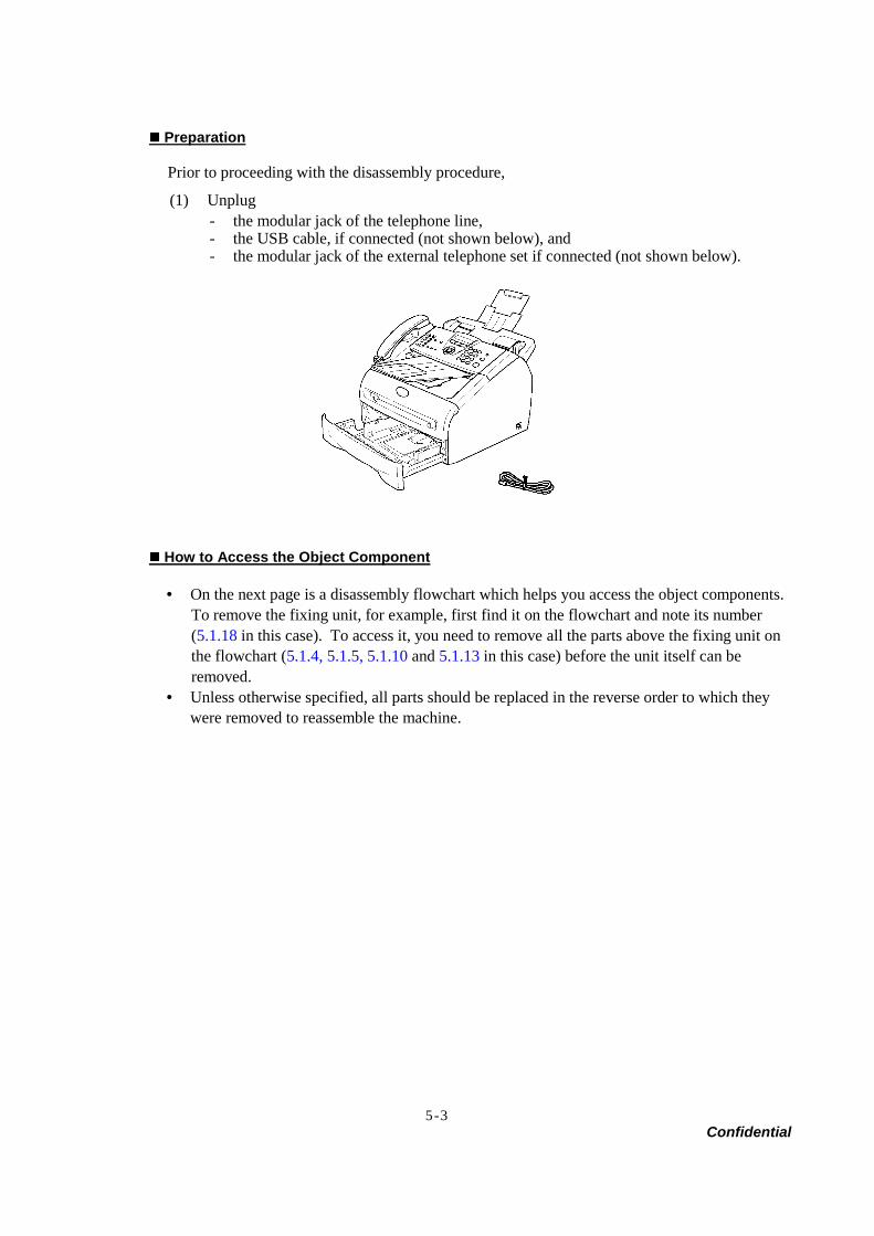
Confidential
5-3
Preparation
Prior to proceeding with the disassembly procedure,
(1) Unplug - the modular jack of the telephone line, - the USB cable, if connected (not shown below), and - the modular jack of the external telephone set if connected (not shown below).
How to Access the Object Component
• On the next page is a disassembly flowchart which helps you access the object components. To remove the fixing unit, for example, first find it on the flowchart and note its number (5.1.18 in this case). To access it, you need to remove all the parts above the fixing unit on the flowchart (5.1.4, 5.1.5, 5.1.10 and 5.1.13 in this case) before the unit itself can be removed.
• Unless otherwise specified, all parts should be replaced in the reverse order to which they were removed to reassemble the machine.
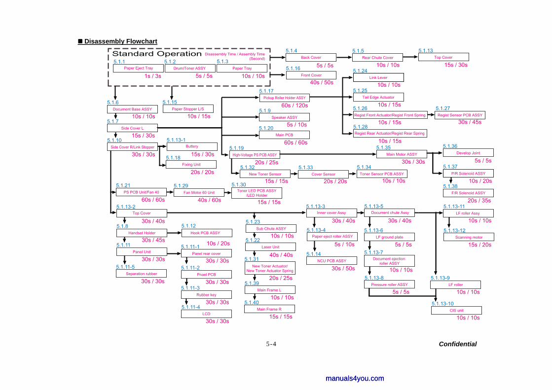
Confidential 5-4
Disassembly Flowchart
5.1.40Main Frame R
5.1.21PS PCB Unit/Fan 40
5.1.29Fan Motor 60 Unit
5.1.30Toner LED PCB ASSY
/LED Holder
5.1.39
5.1.32New Toner Sensor
5.1.33Cover Sensor
5.1.34Toner Sensor PCB ASSY
5.1.38F/R Solenoid ASSY
5.1.36Develop Joint
5.1.37
5.1.35Main Motor ASSY
5.1.15Paper Stopper L/S
5.1.16Front Cover
5.1.23
5.1.31
5.1.22Laser Unit
Standard Operation5.1.1
Paper Eject Tray
1s / 3s
5.1.2Drum/Toner ASSY
5s / 5s
Disassembly Time / Assembly Time
5.1.3Paper Tray
10s / 10s
5.1.4Back Cover
5s / 5s
5.1.5
10s / 10s
5.1.11-1Panel rear cover
30s / 30s5.1.11-2
Pnael PCB
30s / 30s5.1.11-3
Rubber key
30s / 30s5.1.11-4
LCD
30s / 30s
10s / 20s
5.1.12Hook PCB ASSY
Top Cover
5.1.13
15s / 30s
5.1.9Speaker ASSY
5s / 10s5.1.20
Main PCB
60s / 60s
5.1.17
60s / 120s
5.1.19High-Voltage PS PCB ASSY
20s / 25s
5.1.24Link Lever
10s / 10s5.1.25
Tail Edge Actuator
10s / 15s5.1.26Regist Front Actuator/Regist Front Spring
10s / 15s5.1.28Regist Rear Actuator/Regist Rear Spring
10s / 15s
5.1.27Regist Sensor PCB ASSY
30s / 45s
5.1.6Document Base ASSY
10s / 10s5.1.7
Side Cover L
15s / 30s5.1.10
Side Cover R/Link Stopper
30s / 30s
5.1.8
30s / 45s5.1.11
30s / 30s5.1.11-5
Separation rubber
30s / 30s
5.1.18Fixing Unit
20s / 20s
Buttery
5.1.13-1
15s / 30s
5.1.13-2
30s / 40s
5.1.14NCU PCB ASSY
30s / 50s
Inner cover Assy
5.1.13-3
30s / 40s
Paper eject roller ASSY
5.1.13-4
5s / 10s
Document chute Assy
5.1.13-5
30s / 40s
5.1.13-6LF ground plate
5s / 5s5.1.13-7
Document ejection roller ASSY
10s / 10s5.1.13-8
Pressure roller ASSY
5s / 5s
5.1.13-9
10s / 10s
5.1.13-10CIS unit
10s / 10s
5.1.13-11LF roller Assy
10s / 10s
5.1.13-12Scanning motor
15s / 20s
15s / 15s
30s / 30s 5s / 5s
20s / 20s 10s / 10s
40s / 40s
20s / 25s
60s / 60s 40s / 60s 15s / 15s
10s / 20s
20s / 35s
10s / 10s
15s / 15s
10s / 10s
10s / 15s
40s / 50s
Top Cover
Sub Chute ASSY
New Toner Actuator/New Toner Actuator Spring
P/R Solenoid ASSY
Rear Chute Cover(Second)
LF rollerMain Frame L
Handset Holder
Panel Unit
Pickup Roller Holder ASSY
manuals4you.commanuals4you.com
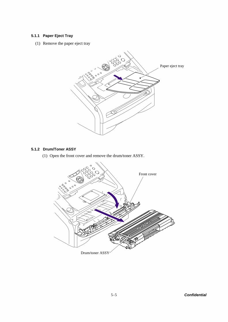
Confidential 5-5
5.1.1 Paper Eject Tray
(1) Remove the paper eject tray
5.1.2 Drum/Toner ASSY (1) Open the front cover and remove the drum/toner ASSY.
Front cover
Drum/toner ASSY
Paper eject tray
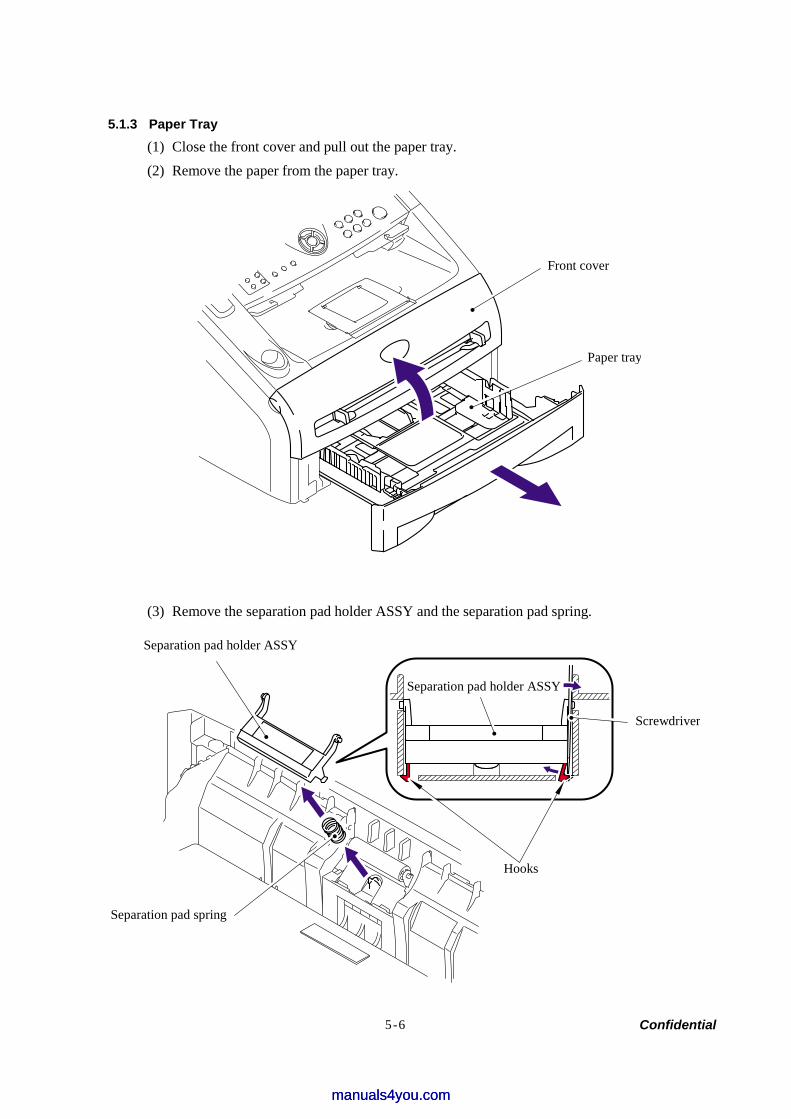
Confidential 5-6
5.1.3 Paper Tray (1) Close the front cover and pull out the paper tray. (2) Remove the paper from the paper tray.
(3) Remove the separation pad holder ASSY and the separation pad spring.
Screwdriver
Separation pad spring
Separation pad holder ASSY
Front cover
Paper tray
Hooks
Separation pad holder ASSY
manuals4you.commanuals4you.com
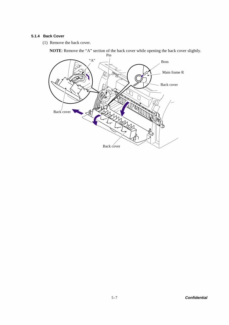
Confidential 5-7
5.1.4 Back Cover (1) Remove the back cover.
NOTE: Remove the “A” section of the back cover while opening the back cover slightly.
Back cover
Boss
Main frame R
Back cover
“A”Pin
Back cover
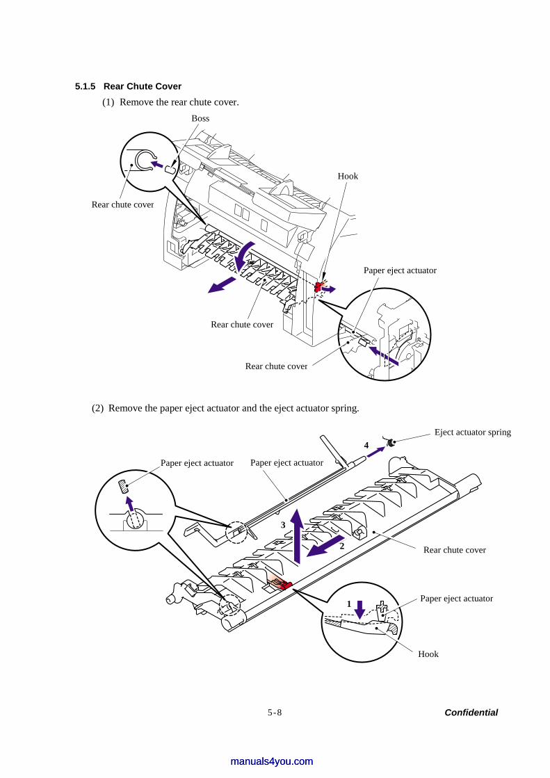
Confidential 5-8
5.1.5 Rear Chute Cover (1) Remove the rear chute cover.
(2) Remove the paper eject actuator and the eject actuator spring.
Boss
Rear chute cover
Rear chute cover
Hook
Paper eject actuator
Rear chute cover
Paper eject actuator
Paper eject actuator
Rear chute cover
Paper eject actuator
Hook
1
2
3
4 Eject actuator spring
manuals4you.commanuals4you.com
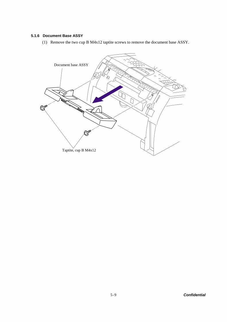
Confidential 5-9
5.1.6 Document Base ASSY (1) Remove the two cup B M4x12 taptite screws to remove the document base ASSY.
Document base ASSY
Taptite, cup B M4x12
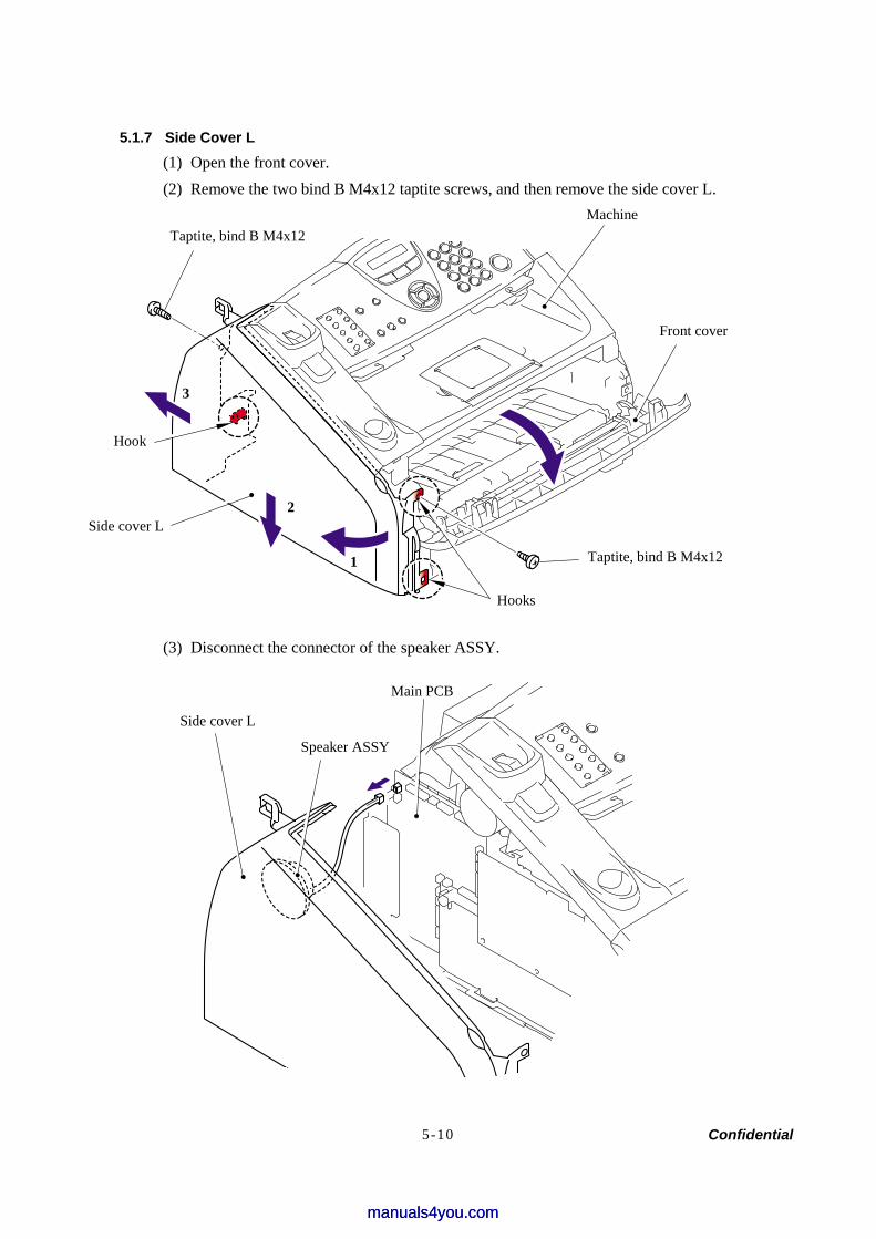
Confidential 5-10
5.1.7 Side Cover L (1) Open the front cover. (2) Remove the two bind B M4x12 taptite screws, and then remove the side cover L.
(3) Disconnect the connector of the speaker ASSY.
Machine Taptite, bind B M4x12
Front cover
Taptite, bind B M4x12
Hooks
Side cover L
Hook
1
2
3
Side cover L
Speaker ASSY
Main PCB
manuals4you.commanuals4you.com
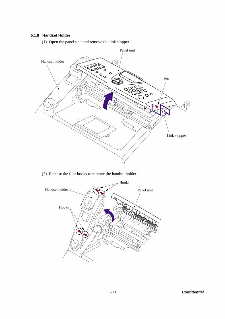
Confidential 5-11
5.1.8 Handset Holder (1) Open the panel unit and remove the link stopper.
(2) Release the four hooks to remove the handset holder.
Panel unit
Handset holder
Link stopper
Hooks
Handset holder
Hooks
Panel unit
Pin

Confidential 5-12
5.1.9 Speaker ASSY (1) Remove the cup B M3x8 taptite screw to remove the speaker hold spring and speaker ASSY.
Speaker ASSY
Speaker hold spring
Taptite, cup B M3x8
Side cover L
manuals4you.commanuals4you.com
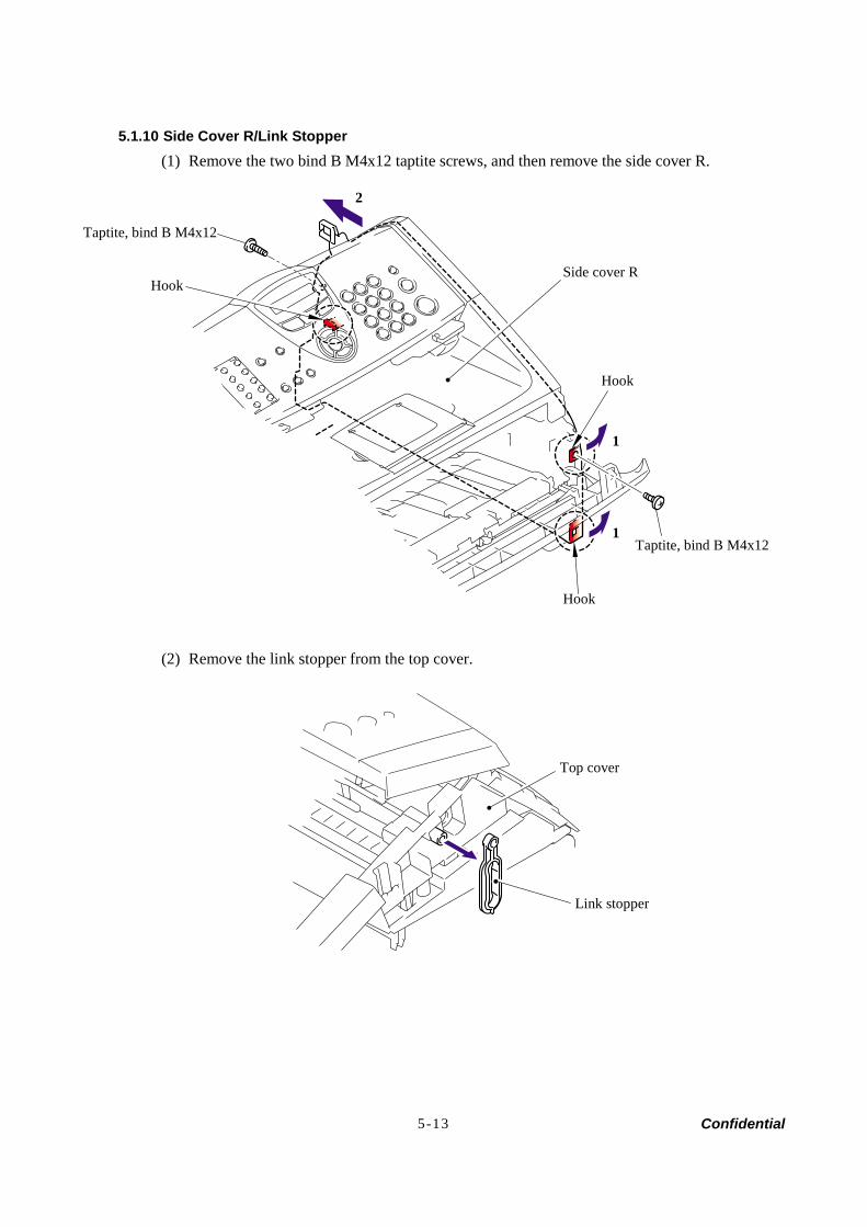
Confidential 5-13
5.1.10 Side Cover R/Link Stopper (1) Remove the two bind B M4x12 taptite screws, and then remove the side cover R.
(2) Remove the link stopper from the top cover.
Taptite, bind B M4x12
Taptite, bind B M4x12
1
1
2
Hook
Hook
Side cover R Hook
Link stopper
Top cover
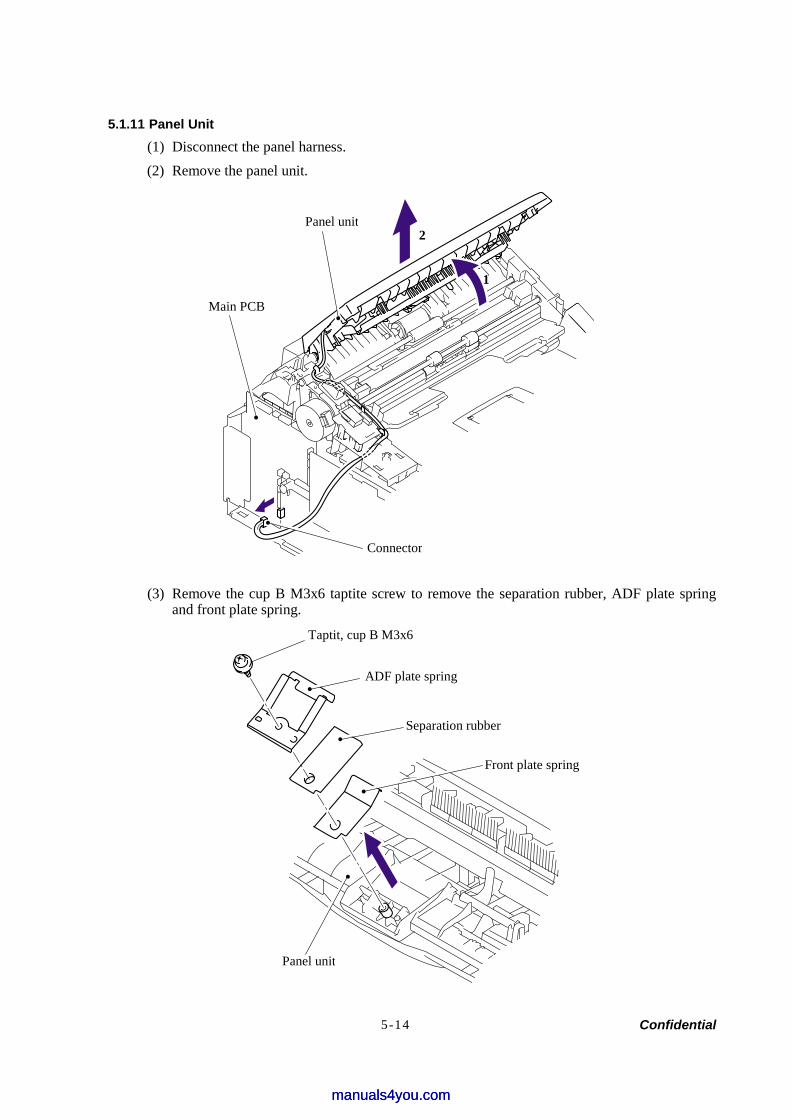
Confidential 5-14
5.1.11 Panel Unit (1) Disconnect the panel harness. (2) Remove the panel unit.
(3) Remove the cup B M3x6 taptite screw to remove the separation rubber, ADF plate spring and front plate spring.
Panel unit
Main PCB
Connector
ADF plate spring
Front plate spring
Separation rubber
Taptit, cup B M3x6
Panel unit
1
2
manuals4you.commanuals4you.com
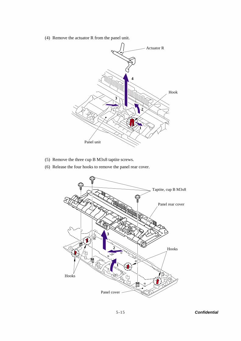
Confidential 5-15
(4) Remove the actuator R from the panel unit.
(5) Remove the three cup B M3x8 taptite screws. (6) Release the four hooks to remove the panel rear cover.
Actuator R
Hook
Panel unit
1
2
3
4
Hooks
Hooks
Panel cover
Panel rear cover
Taptite, cup B M3x8
1
2
3
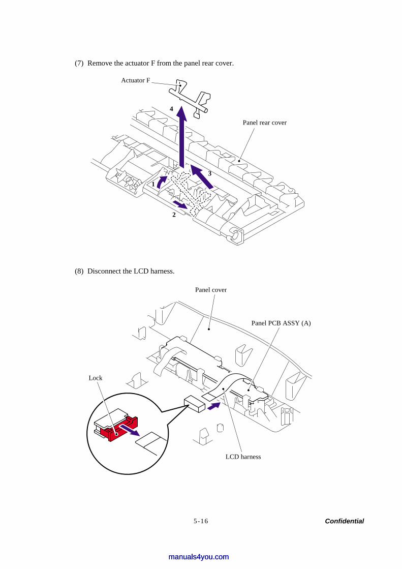
Confidential 5-16
(7) Remove the actuator F from the panel rear cover.
(8) Disconnect the LCD harness.
Actuator F
Panel rear cover
1 3
2
Panel PCB ASSY (A)
Panel cover
LCD harness
4
Lock
manuals4you.commanuals4you.com
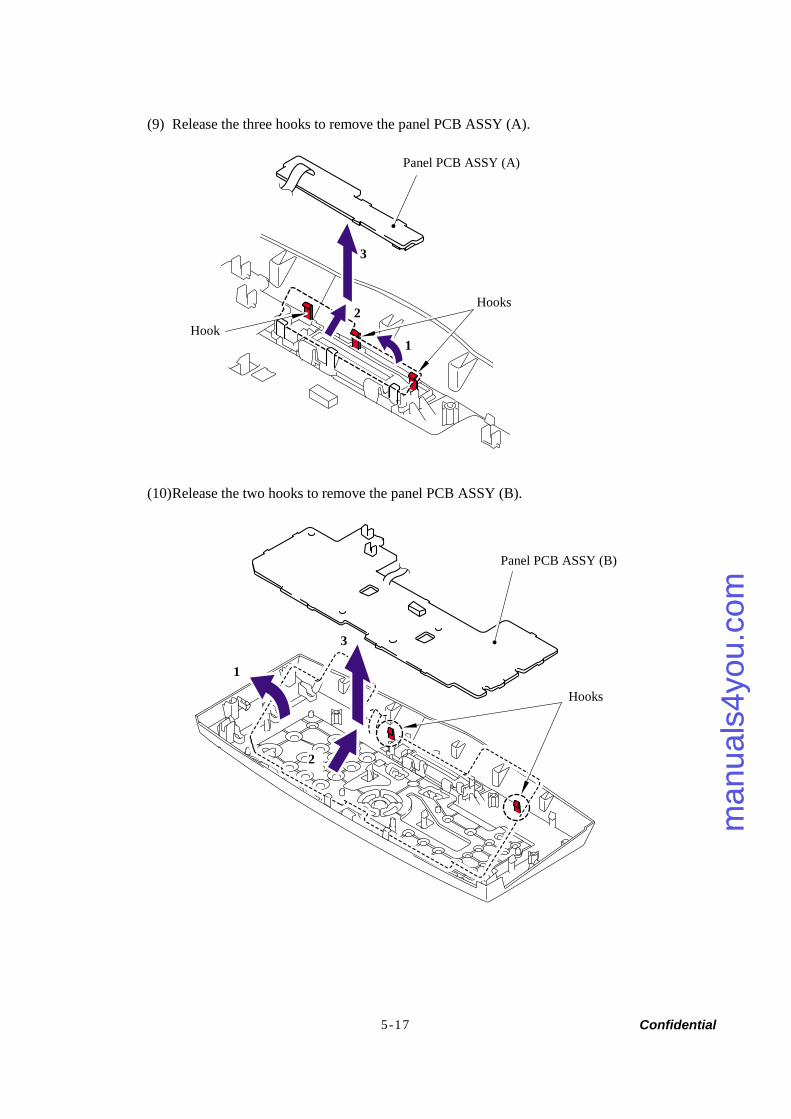
Confidential 5-17
(9) Release the three hooks to remove the panel PCB ASSY (A).
(10) Release the two hooks to remove the panel PCB ASSY (B).
Panel PCB ASSY (A)
Hooks
1
2
Panel PCB ASSY (B)
Hooks
3
2
3
1
Hook
man
uals
4you
.com
man
uals
4you
.com
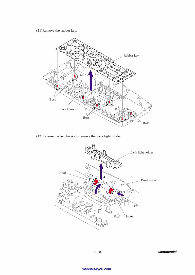
Confidential 5-18
(11) Remove the rubber key.
(12) Release the two hooks to remove the back light holder.
Rubber key
Panel cover
Back light holder
Hook
Hook
Panel cover
1
1
2 3
4
Boss
Boss
Boss
manuals4you.commanuals4you.com
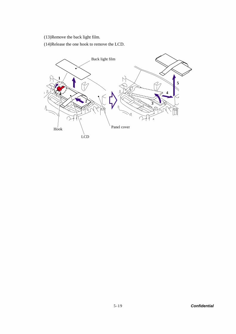
Confidential 5-19
(13) Remove the back light film. (14) Release the one hook to remove the LCD.
Back light film
Hook
LCD
Panel cover
1
2
5
4
3
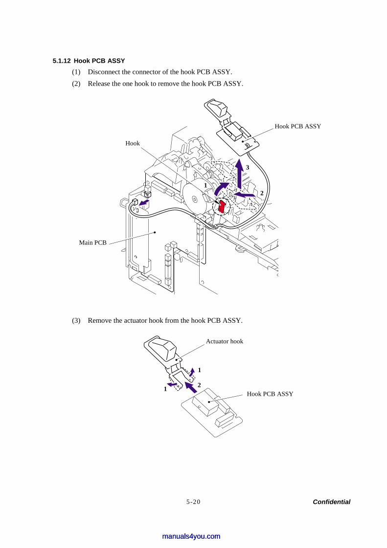
Confidential 5-20
5.1.12 Hook PCB ASSY (1) Disconnect the connector of the hook PCB ASSY. (2) Release the one hook to remove the hook PCB ASSY.
(3) Remove the actuator hook from the hook PCB ASSY.
Hook PCB ASSY
Hook
Main PCB
12
3
Hook PCB ASSY
Actuator hook
1
1
2
manuals4you.commanuals4you.com
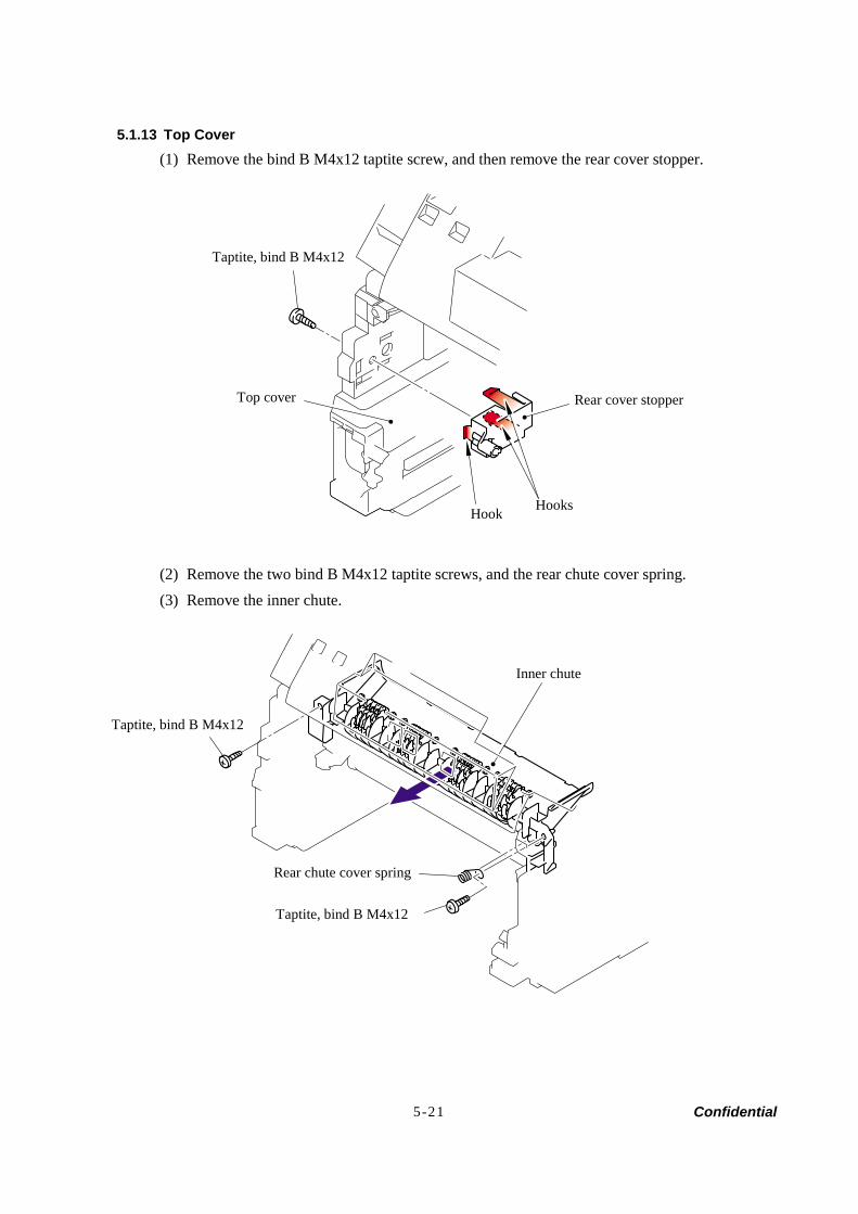
Confidential 5-21
5.1.13 Top Cover (1) Remove the bind B M4x12 taptite screw, and then remove the rear cover stopper.
(2) Remove the two bind B M4x12 taptite screws, and the rear chute cover spring. (3) Remove the inner chute.
Hooks
Taptite, bind B M4x12
Rear cover stopperTop cover
Inner chute
Rear chute cover spring
Taptite, bind B M4x12
Taptite, bind B M4x12
Hook
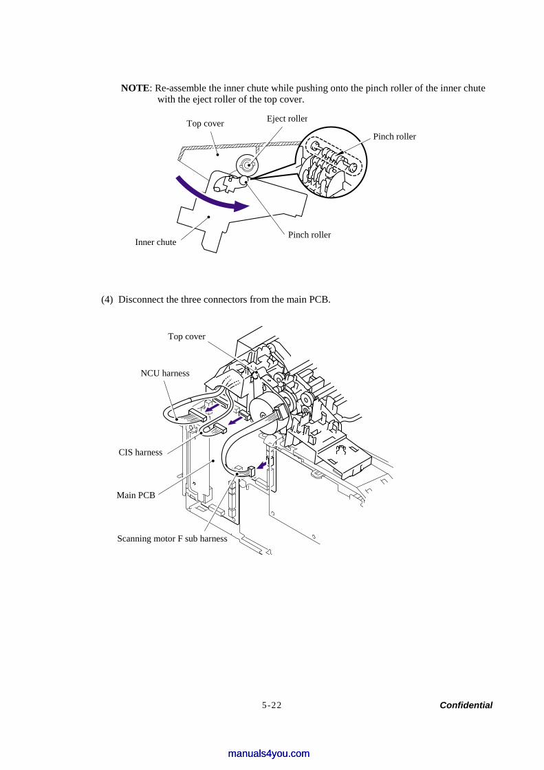
Confidential 5-22
NOTE: Re-assemble the inner chute while pushing onto the pinch roller of the inner chute with the eject roller of the top cover.
(4) Disconnect the three connectors from the main PCB.
Main PCB
Top cover
Top cover Eject roller
Inner chute Pinch roller
Pinch roller
NCU harness
CIS harness
Scanning motor F sub harness
manuals4you.commanuals4you.com

Confidential 5-23
(5) Remove the one pan (S/P washer) M3.5x6 screw to remove the NCU FG harness ASSY.
(6) Disconnect the connector of the buttery. (7) Release the one hook to remove the buttery. (8) Disconnect the buttery harness from the main PCB
Main frame R
Screws, pan (S/P washer) M3.5x6
NCU FG harness ASSY 1
Main PCB
Buttery harness
Hook
Buttery
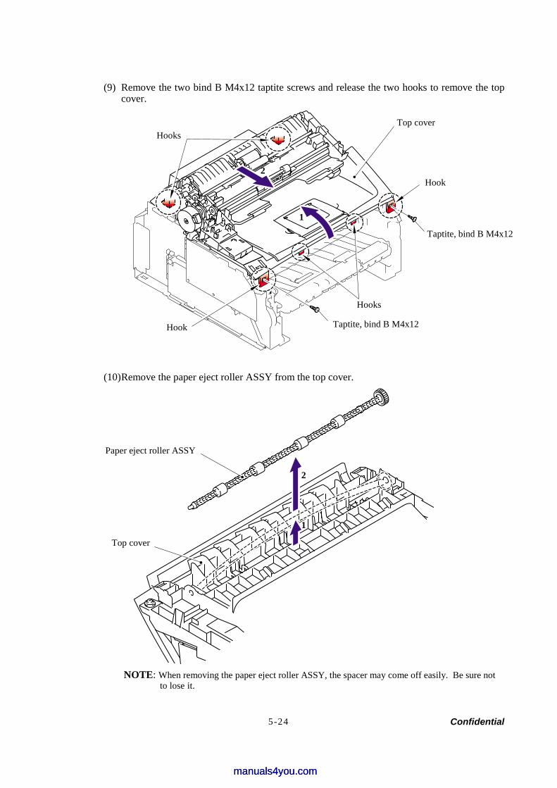
Confidential 5-24
(9) Remove the two bind B M4x12 taptite screws and release the two hooks to remove the top cover.
(10) Remove the paper eject roller ASSY from the top cover.
NOTE: When removing the paper eject roller ASSY, the spacer may come off easily. Be sure not
to lose it.
Top cover
Paper eject roller ASSY
Hooks
Hooks
Hook
Hook
Top cover
Taptite, bind B M4x12
Taptite, bind B M4x12
1
2
2
1
manuals4you.commanuals4you.com
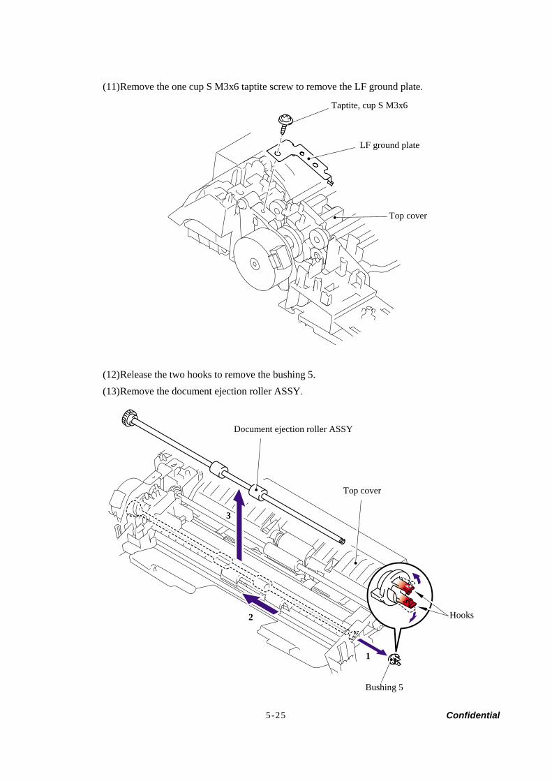
Confidential 5-25
(11) Remove the one cup S M3x6 taptite screw to remove the LF ground plate.
(12) Release the two hooks to remove the bushing 5. (13) Remove the document ejection roller ASSY.
Taptite, cup S M3x6
LF ground plate
Top cover
Document ejection roller ASSY
Top cover
Bushing 5
2
1
3
Hooks
1
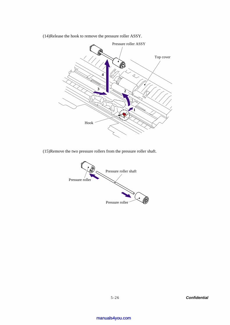
Confidential 5-26
(14) Release the hook to remove the pressure roller ASSY.
(15) Remove the two pressure rollers from the pressure roller shaft.
Pressure roller ASSY
Top cover
Hook
1
3
4
Pressure roller shaft
Pressure roller
Pressure roller
2
manuals4you.commanuals4you.com
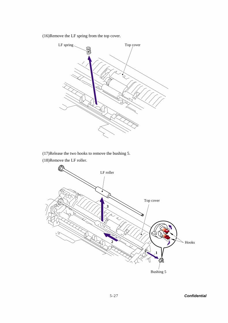
Confidential 5-27
(16) Remove the LF spring from the top cover.
(17) Release the two hooks to remove the bushing 5. (18) Remove the LF roller.
Top cover LF spring
Bushing 5
LF roller
Top cover
1
2
3
Hooks
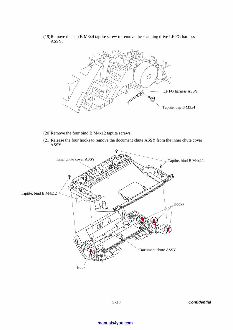
Confidential 5-28
(19) Remove the cup B M3x4 taptite screw to remove the scanning drive LF FG harness ASSY.
(20) Remove the four bind B M4x12 taptite screws. (21) Release the four hooks to remove the document chute ASSY from the inner chute cover
ASSY.
Taptite, bind B M4x12
Taptite, bind B M4x12
Hooks
Hook
Document chute ASSY
Inner chute cover ASSY
LF FG harness ASSY
Taptite, cup B M3x4
manuals4you.commanuals4you.com
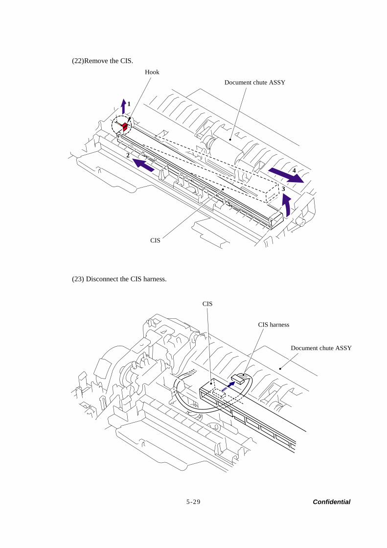
Confidential 5-29
(22) Remove the CIS.
(23) Disconnect the CIS harness.
Document chute ASSY Hook
CIS
1
2
3
4
Document chute ASSY
CIS
CIS harness
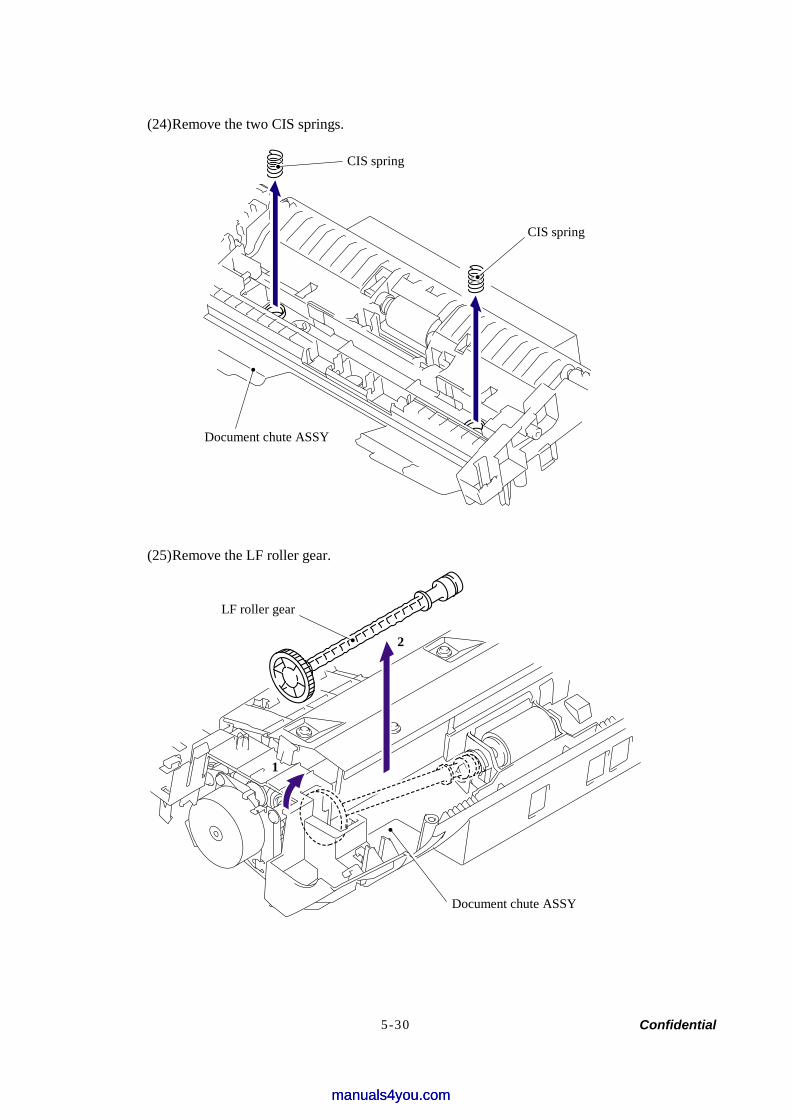
Confidential 5-30
(24) Remove the two CIS springs.
(25) Remove the LF roller gear.
CIS spring
CIS spring
Document chute ASSY
LF roller gear
Document chute ASSY
1
2
manuals4you.commanuals4you.com
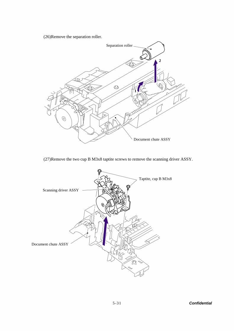
Confidential 5-31
(26) Remove the separation roller.
(27) Remove the two cup B M3x8 taptite screws to remove the scanning driver ASSY.
Document chute ASSY
Separation roller
Document chute ASSY
Scanning driver ASSY
Taptite, cup B M3x8
1
2
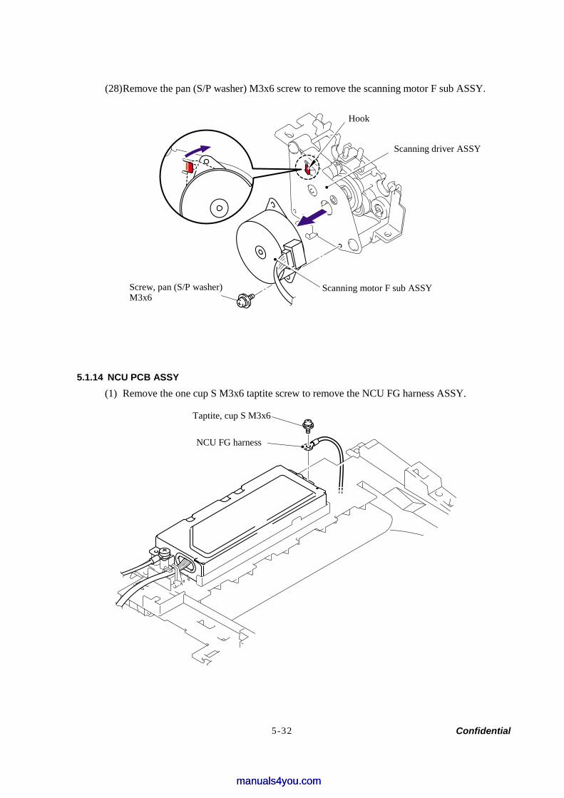
Confidential 5-32
(28) Remove the pan (S/P washer) M3x6 screw to remove the scanning motor F sub ASSY.
5.1.14 NCU PCB ASSY (1) Remove the one cup S M3x6 taptite screw to remove the NCU FG harness ASSY.
Scanning driver ASSY
Scanning motor F sub ASSY
Hook
Taptite, cup S M3x6
NCU FG harness
Screw, pan (S/P washer) M3x6
manuals4you.commanuals4you.com
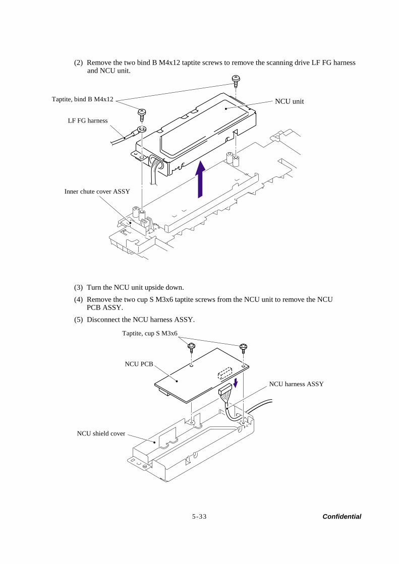
Confidential 5-33
(2) Remove the two bind B M4x12 taptite screws to remove the scanning drive LF FG harness and NCU unit.
(3) Turn the NCU unit upside down. (4) Remove the two cup S M3x6 taptite screws from the NCU unit to remove the NCU
PCB ASSY. (5) Disconnect the NCU harness ASSY.
Taptite, bind B M4x12 NCU unit
Inner chute cover ASSY
Taptite, cup S M3x6
NCU PCB
NCU shield cover
NCU harness ASSY
LF FG harness
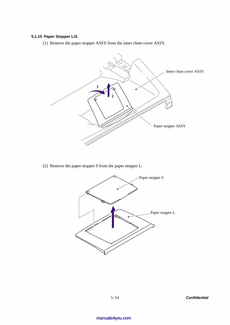
Confidential 5-34
5.1.15 Paper Stopper L/S (1) Remove the paper stopper ASSY from the inner chute cover ASSY.
(2) Remove the paper stopper S from the paper stopper L.
Inner chute cover ASSY
Paper stopper ASSY
Paper stopper L
Paper stopper S
2
1
manuals4you.commanuals4you.com
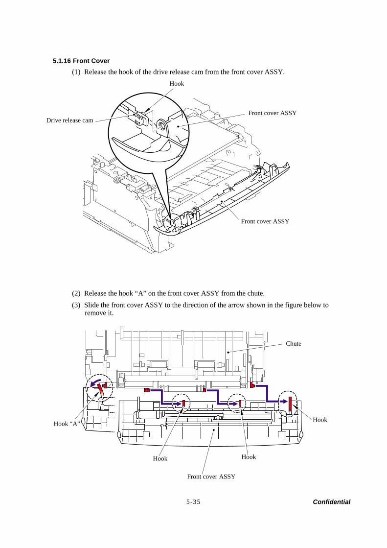
Confidential 5-35
5.1.16 Front Cover (1) Release the hook of the drive release cam from the front cover ASSY.
(2) Release the hook “A” on the front cover ASSY from the chute. (3) Slide the front cover ASSY to the direction of the arrow shown in the figure below to
remove it.
Hook
Front cover ASSY Drive release cam
Front cover ASSY
Chute
Hook
Hook
Front cover ASSY
Hook
Hook “A”
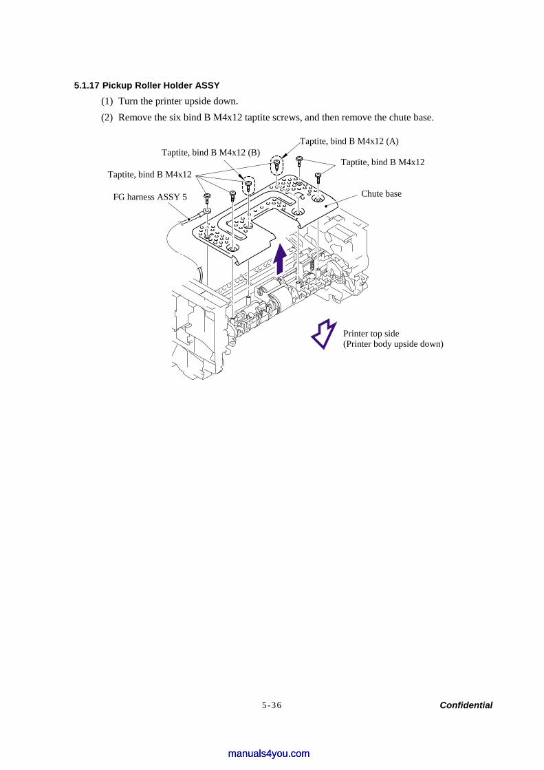
Confidential 5-36
5.1.17 Pickup Roller Holder ASSY (1) Turn the printer upside down. (2) Remove the six bind B M4x12 taptite screws, and then remove the chute base.
FG harness ASSY 5
Taptite, bind B M4x12
Taptite, bind B M4x12 (B) Taptite, bind B M4x12
Chute base
Printer top side (Printer body upside down)
Taptite, bind B M4x12 (A)
manuals4you.commanuals4you.com
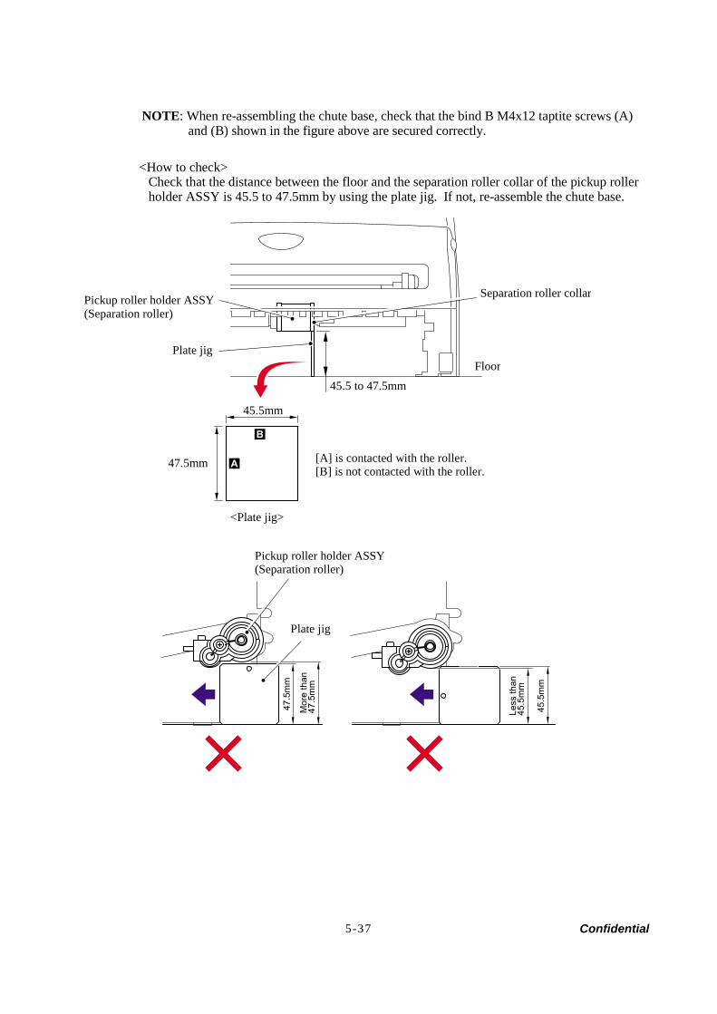
Confidential 5-37
NOTE: When re-assembling the chute base, check that the bind B M4x12 taptite screws (A) and (B) shown in the figure above are secured correctly.
<How to check> Check that the distance between the floor and the separation roller collar of the pickup roller holder ASSY is 45.5 to 47.5mm by using the plate jig. If not, re-assemble the chute base.
B
A
47.5
mm
Mor
e th
an47
.5m
m
45.5
mm
Less
than
45.5
mm
Separation roller collar
FloorPlate jig
47.5mm
45.5mm
[A] is contacted with the roller.[B] is not contacted with the roller.
<Plate jig>
45.5 to 47.5mm
Pickup roller holder ASSY(Separation roller)
Plate jig
Pickup roller holder ASSY(Separation roller)
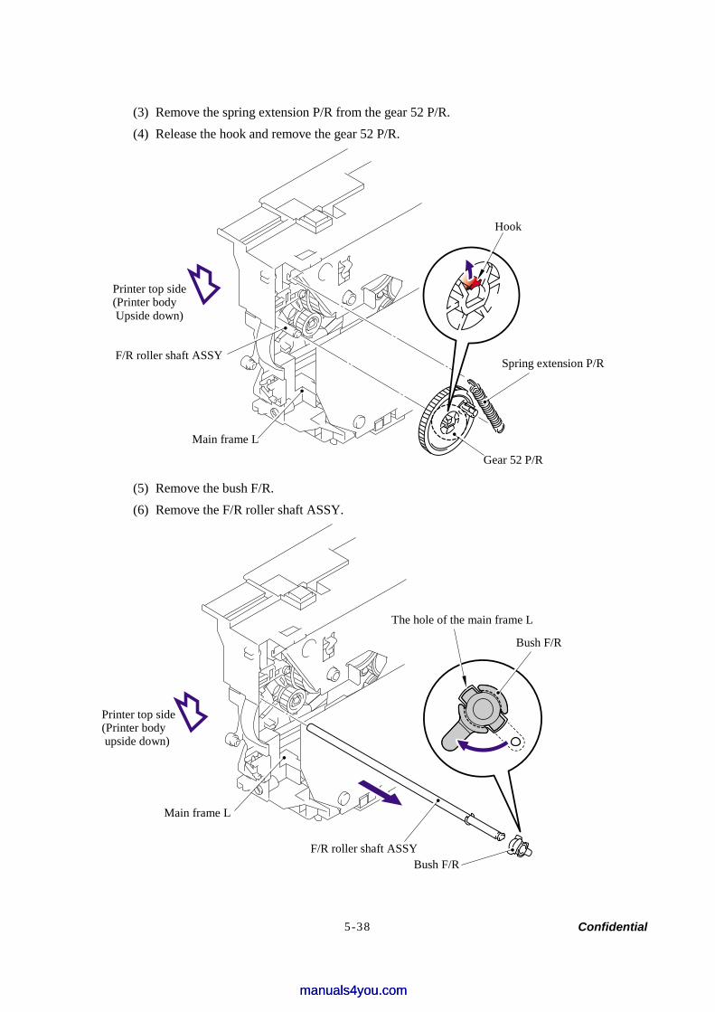
Confidential 5-38
(3) Remove the spring extension P/R from the gear 52 P/R. (4) Release the hook and remove the gear 52 P/R.
(5) Remove the bush F/R. (6) Remove the F/R roller shaft ASSY.
The hole of the main frame L
Bush F/R
Hook
Spring extension P/R
Printer top side (Printer body Upside down)
F/R roller shaft ASSY
Main frame L
Gear 52 P/R
Printer top side (Printer body upside down)
F/R roller shaft ASSYBush F/R
Main frame L
manuals4you.commanuals4you.com
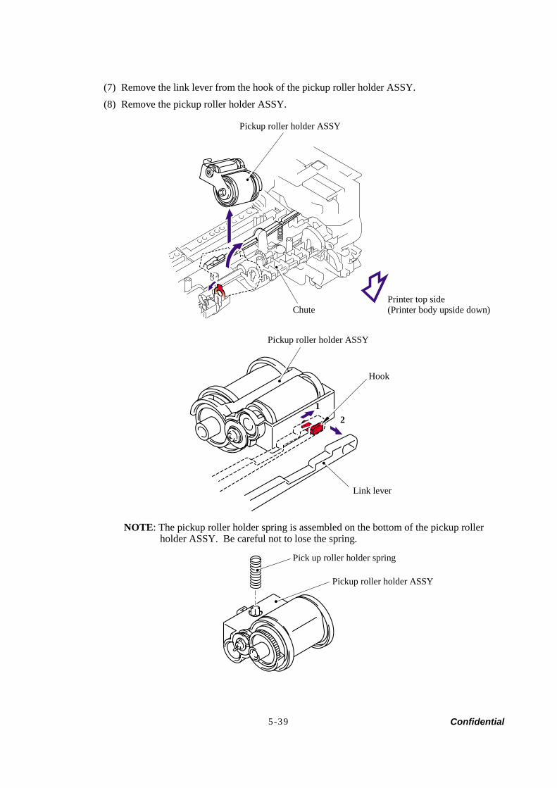
Confidential 5-39
(7) Remove the link lever from the hook of the pickup roller holder ASSY. (8) Remove the pickup roller holder ASSY.
NOTE: The pickup roller holder spring is assembled on the bottom of the pickup roller holder ASSY. Be careful not to lose the spring.
Pickup roller holder ASSY
ChutePrinter top side (Printer body upside down)
Pickup roller holder ASSY
Hook
Link lever
12
Pick up roller holder spring
Pickup roller holder ASSY
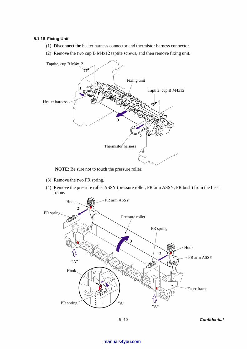
Confidential 5-40
5.1.18 Fixing Unit (1) Disconnect the heater harness connector and thermistor harness connector. (2) Remove the two cup B M4x12 taptite screws, and then remove fixing unit.
NOTE: Be sure not to touch the pressure roller.
(3) Remove the two PR spring. (4) Remove the pressure roller ASSY (pressure roller, PR arm ASSY, PR bush) from the fuser
frame.
Taptite, cup B M4x12
Fixing unit
Taptite, cup B M4x12
Heater harness
1
3
2
Thermistor harness
PR arm ASSYHook
PR spring Pressure roller
PR spring
Hook
PR arm ASSY
Fuser frame
“A” “A”
Hook
PR spring
“A”
3
2
2
1
manuals4you.commanuals4you.com
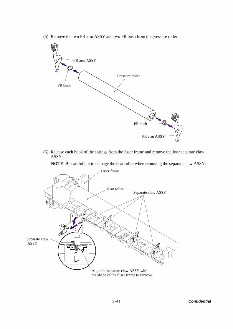
Confidential 5-41
(5) Remove the two PR arm ASSY and two PR bush from the pressure roller.
(6) Release each hook of the springs from the fuser frame and remove the four separate claw ASSYs. NOTE: Be careful not to damage the heat roller when removing the separate claw ASSY.
PR arm ASSY
PR bush
Pressure roller
PR bush
PR arm ASSY
Fuser frame
Heat rollerSeparate claw ASSY
Separate claw ASSY
Align the separate claw ASSY withthe shape of the fuser frame to remove.
1
2
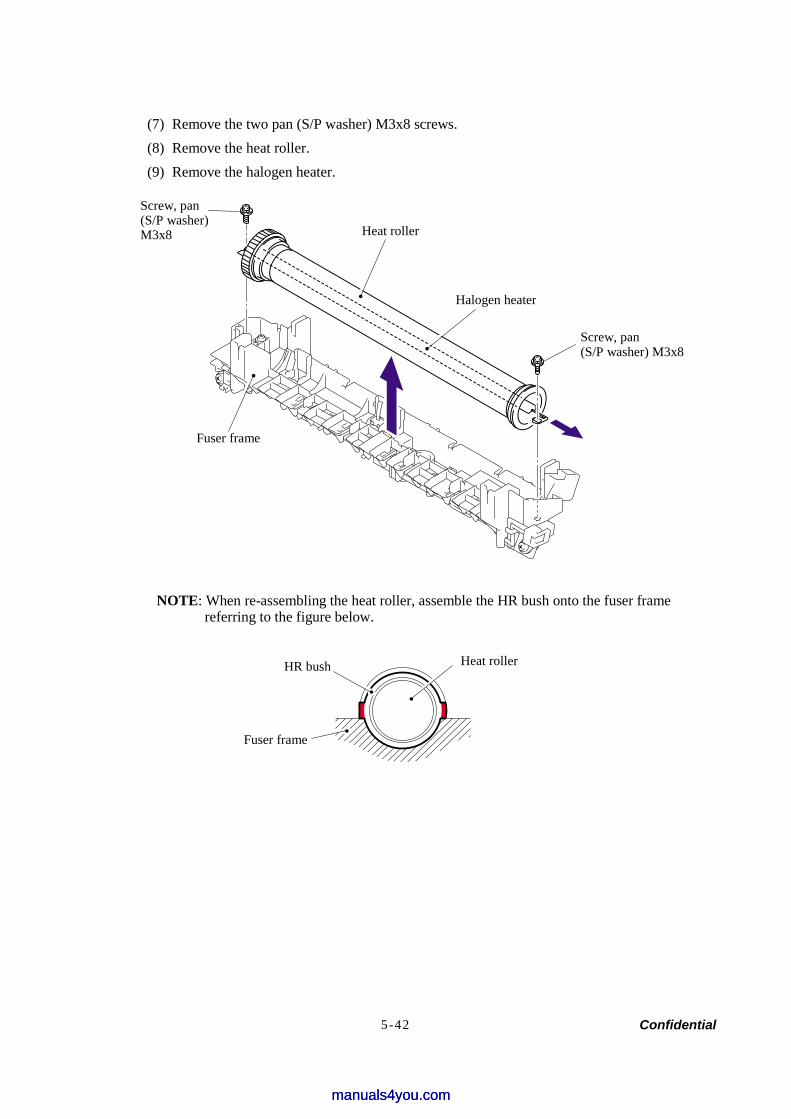
Confidential 5-42
(7) Remove the two pan (S/P washer) M3x8 screws. (8) Remove the heat roller. (9) Remove the halogen heater.
NOTE: When re-assembling the heat roller, assemble the HR bush onto the fuser frame referring to the figure below.
Screw, pan (S/P washer) M3x8 Heat roller
Halogen heater
Screw, pan(S/P washer) M3x8
Fuser frame
HR bush Heat roller
Fuser frame
manuals4you.commanuals4you.com
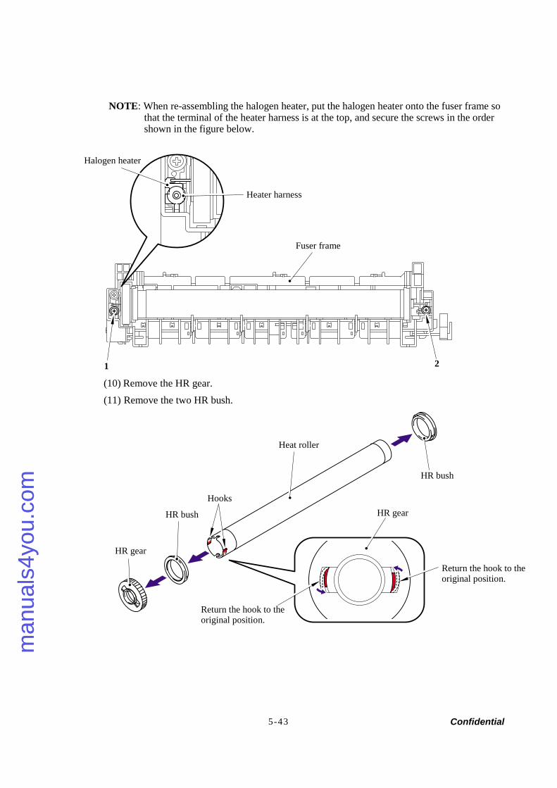
Confidential 5-43
NOTE: When re-assembling the halogen heater, put the halogen heater onto the fuser frame so that the terminal of the heater harness is at the top, and secure the screws in the order shown in the figure below.
(10) Remove the HR gear. (11) Remove the two HR bush.
Halogen heater
Heater harness
Fuser frame
1 2
Heat roller
HR bush
Hooks
HR bush
HR gear
Return the hook to the original position.
HR gear
Return the hook to the original position.
man
uals
4you
.com
man
uals
4you
.com
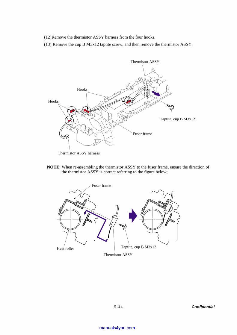
Confidential 5-44
(12) Remove the thermistor ASSY harness from the four hooks. (13) Remove the cup B M3x12 taptite screw, and then remove the thermistor ASSY.
NOTE: When re-assembling the thermistor ASSY to the fuser frame, ensure the direction of the thermistor ASSY is correct referring to the figure below;
Thermistor ASSY
Taptite, cup B M3x12
Hooks
Hooks
Fuser frame
Thermistor ASSY harness
Fuser frame
Heat roller Thermistor ASSY
Taptite, cup B M3x12
manuals4you.commanuals4you.com
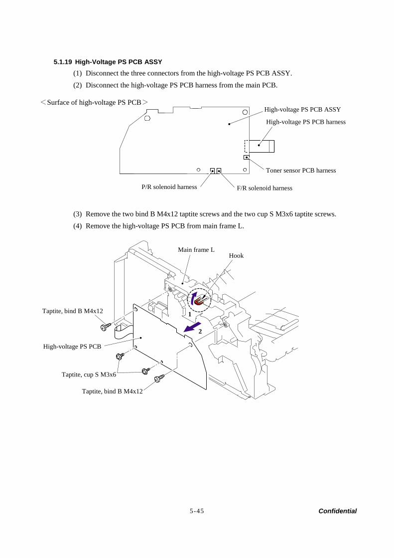
Confidential 5-45
5.1.19 High-Voltage PS PCB ASSY (1) Disconnect the three connectors from the high-voltage PS PCB ASSY. (2) Disconnect the high-voltage PS PCB harness from the main PCB.
(3) Remove the two bind B M4x12 taptite screws and the two cup S M3x6 taptite screws. (4) Remove the high-voltage PS PCB from main frame L.
High-voltage PS PCB harness
Toner sensor PCB harness
P/R solenoid harness F/R solenoid harness
Main frame L Hook
Taptite, bind B M4x12
High-voltage PS PCB
Taptite, cup S M3x6
Taptite, bind B M4x12
1
2
High-voltage PS PCB ASSY <Surface of high-voltage PS PCB>
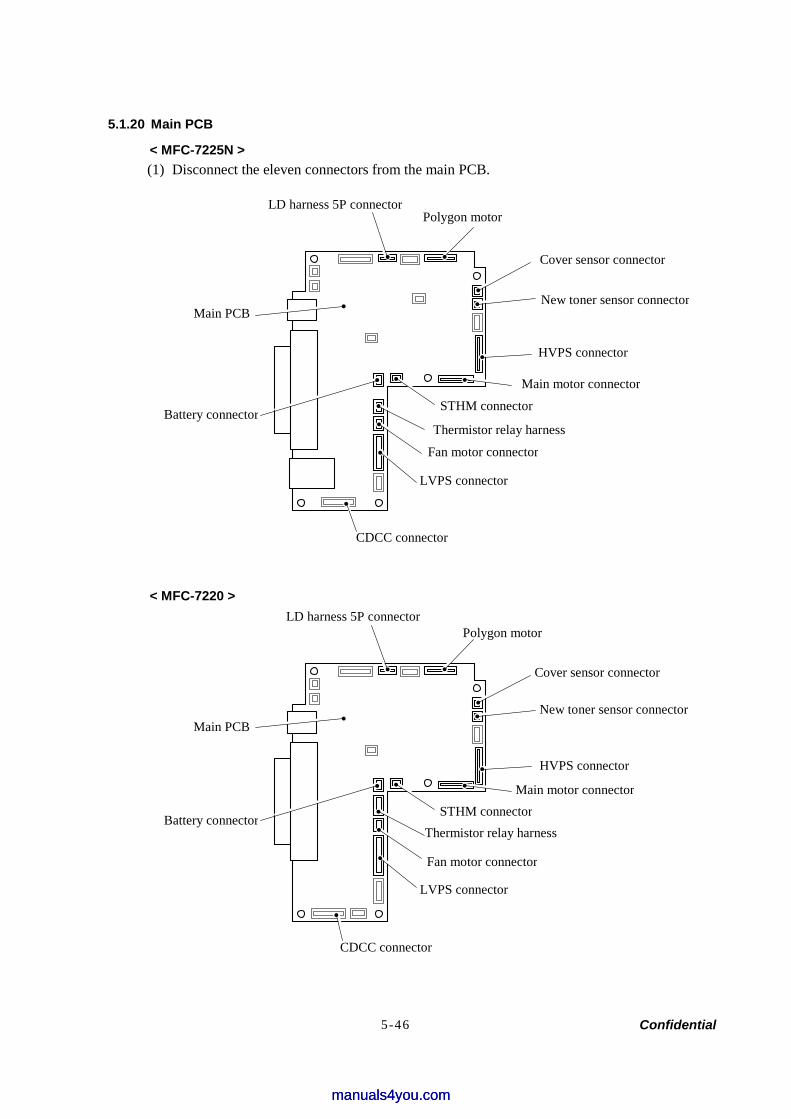
Confidential 5-46
5.1.20 Main PCB
< MFC-7225N > (1) Disconnect the eleven connectors from the main PCB.
< MFC-7220 >
HVPS connector
New toner sensor connector
Polygon motor
Main PCB
Cover sensor connector
LVPS connector
Fan motor connector
Thermistor relay harness
Main motor connector
Battery connector
LD harness 5P connector
Battery connector
Main PCB
LVPS connector
Fan motor connector
Thermistor relay harness
Main motor connector
HVPS connector
New toner sensor connector
Cover sensor connector
Polygon motorLD harness 5P connector
STHM connector
STHM connector
CDCC connector
CDCC connector
manuals4you.commanuals4you.com
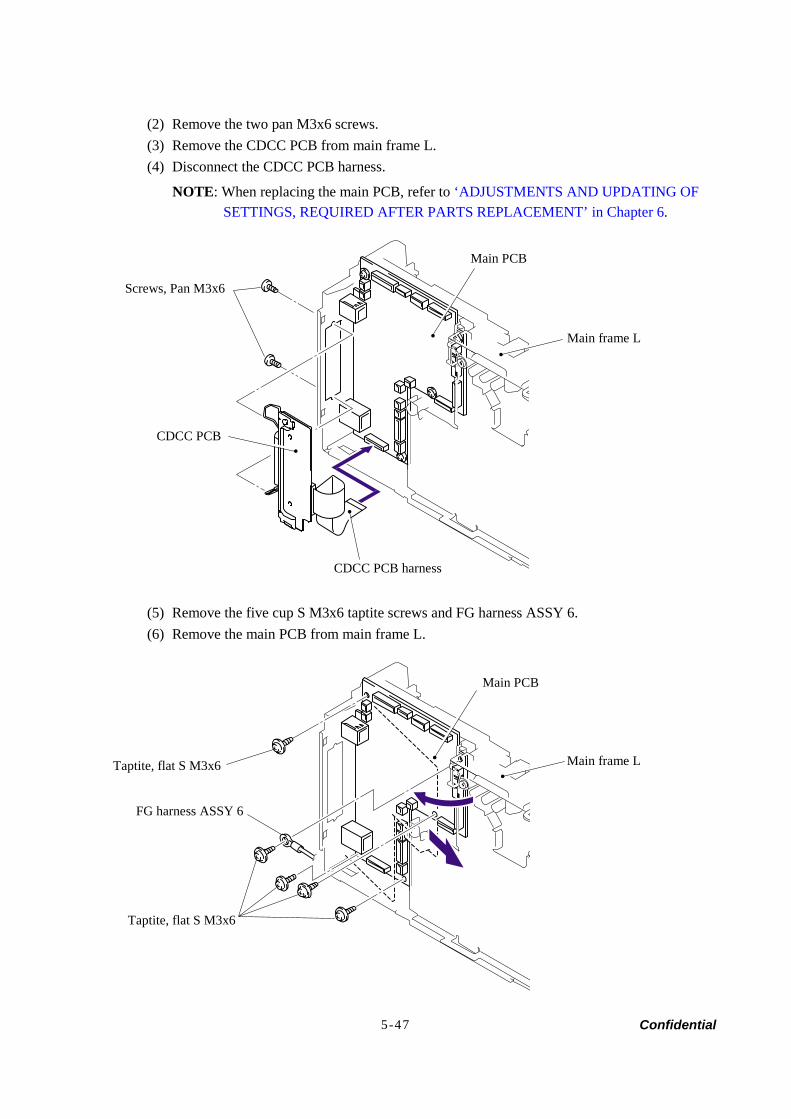
Confidential 5-47
(2) Remove the two pan M3x6 screws. (3) Remove the CDCC PCB from main frame L. (4) Disconnect the CDCC PCB harness.
NOTE: When replacing the main PCB, refer to ‘ADJUSTMENTS AND UPDATING OF SETTINGS, REQUIRED AFTER PARTS REPLACEMENT’ in Chapter 6.
(5) Remove the five cup S M3x6 taptite screws and FG harness ASSY 6. (6) Remove the main PCB from main frame L.
Main PCB
Screws, Pan M3x6
CDCC PCB harness
Main frame L
Taptite, flat S M3x6
Taptite, flat S M3x6
FG harness ASSY 6
Main frame L
Main PCB
CDCC PCB
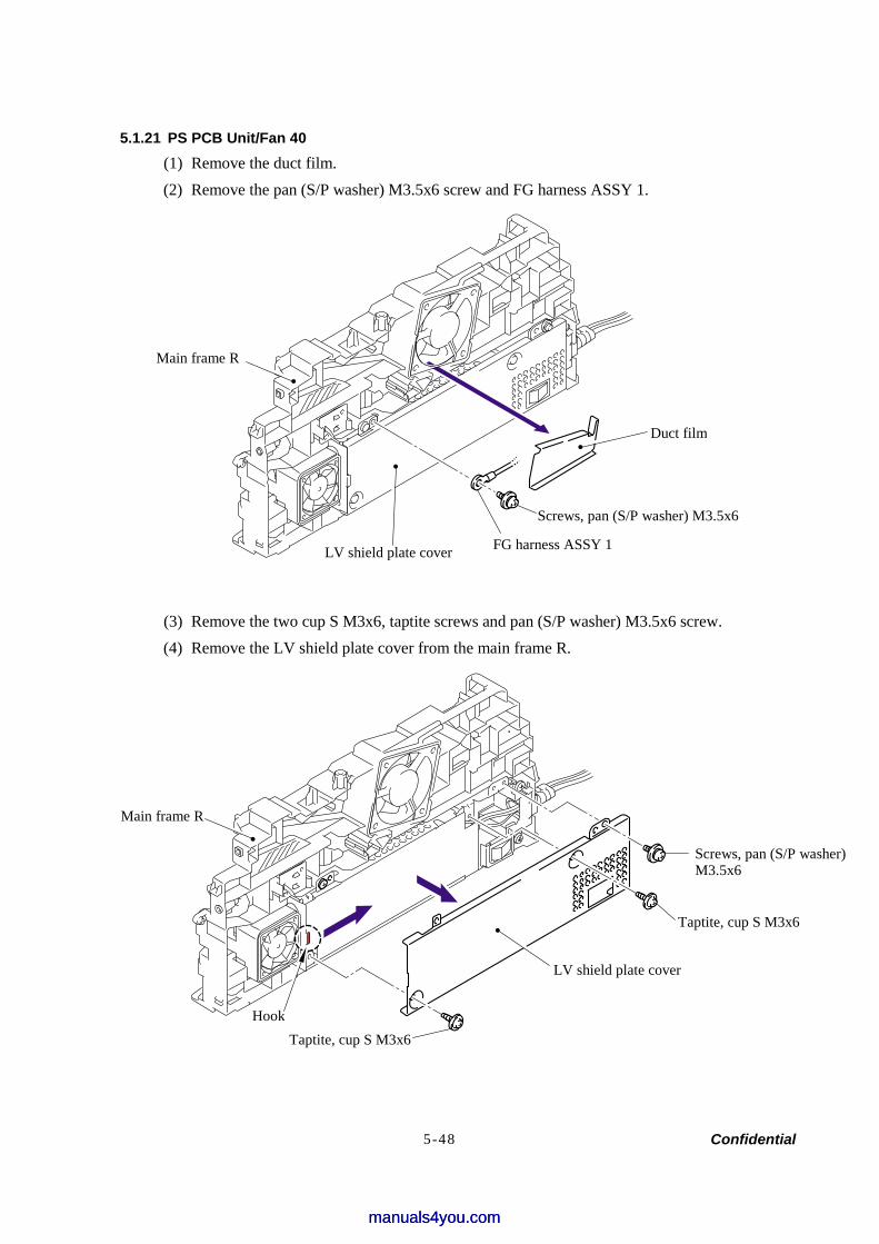
Confidential 5-48
5.1.21 PS PCB Unit/Fan 40 (1) Remove the duct film. (2) Remove the pan (S/P washer) M3.5x6 screw and FG harness ASSY 1.
(3) Remove the two cup S M3x6, taptite screws and pan (S/P washer) M3.5x6 screw. (4) Remove the LV shield plate cover from the main frame R.
Hook
Taptite, cup S M3x6
Screws, pan (S/P washer) M3.5x6
LV shield plate cover
Main frame R
Screws, pan (S/P washer) M3.5x6
LV shield plate cover
Taptite, cup S M3x6
Main frame R
FG harness ASSY 1
Duct film
manuals4you.commanuals4you.com
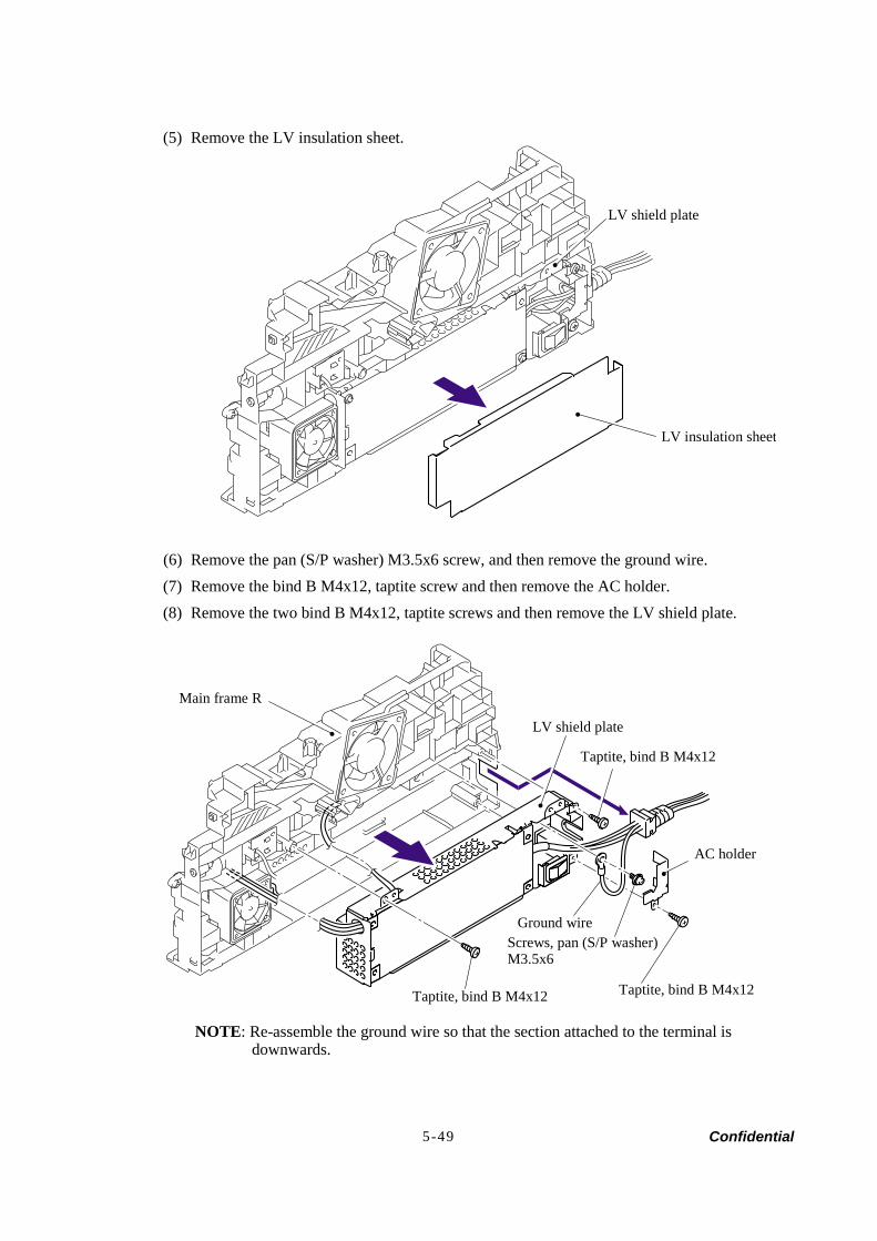
Confidential 5-49
(5) Remove the LV insulation sheet.
(6) Remove the pan (S/P washer) M3.5x6 screw, and then remove the ground wire. (7) Remove the bind B M4x12, taptite screw and then remove the AC holder. (8) Remove the two bind B M4x12, taptite screws and then remove the LV shield plate.
NOTE: Re-assemble the ground wire so that the section attached to the terminal is downwards.
LV shield plate
LV insulation sheet
Main frame R
LV shield plate
Ground wireScrews, pan (S/P washer) M3.5x6
Taptite, bind B M4x12
AC holder
Taptite, bind B M4x12
Taptite, bind B M4x12
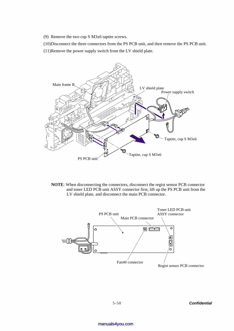
Confidential 5-50
(9) Remove the two cup S M3x6 taptite screws. (10) Disconnect the three connectors from the PS PCB unit, and then remove the PS PCB unit. (11) Remove the power supply switch from the LV shield plate.
NOTE: When disconnecting the connectors, disconnect the regist sensor PCB connector and toner LED PCB unit ASSY connector first, lift up the PS PCB unit from the LV shield plate, and disconnect the main PCB connector.
PS PCB unitToner LED PCB unit ASSY connector
Regist sensor PCB connector
Main PCB connector
LV shield plate Power supply switch
PS PCB unit
Taptite, cup S M3x6
Taptite, cup S M3x6
Main frame R
Fan40 connector
manuals4you.commanuals4you.com
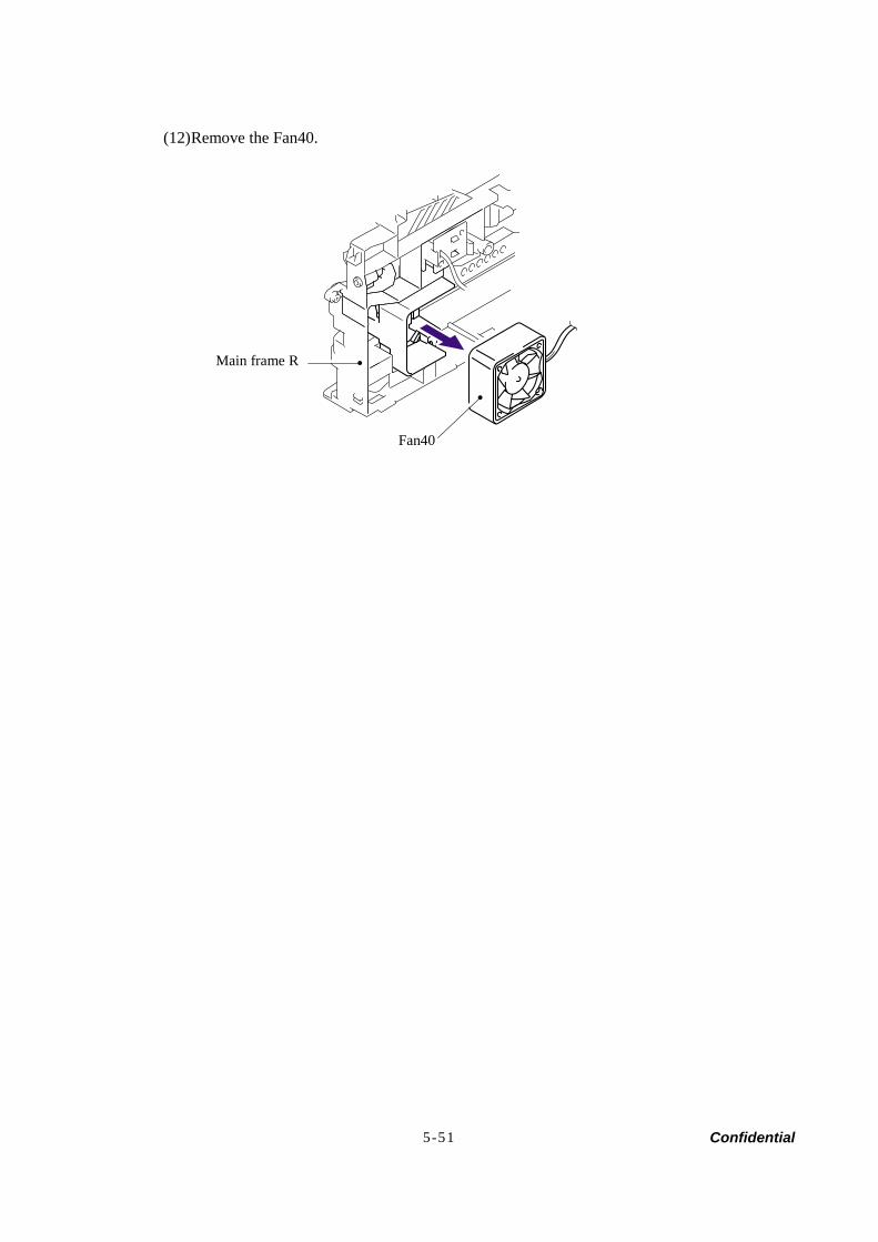
Confidential 5-51
(12) Remove the Fan40.
Fan40
Main frame R
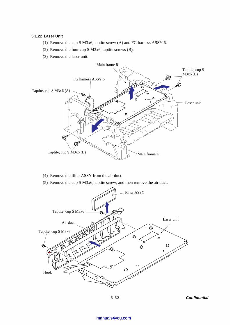
Confidential 5-52
5.1.22 Laser Unit (1) Remove the cup S M3x6, taptite screw (A) and FG harness ASSY 6. (2) Remove the four cup S M3x6, taptite screws (B). (3) Remove the laser unit.
(4) Remove the filter ASSY from the air duct. (5) Remove the cup S M3x6, taptite screw, and then remove the air duct.
Taptite, cup SM3x6 (B)
Main frame R
Taptite, cup S M3x6 (B)
Filter ASSY
Taptite, cup S M3x6
Air duct
Hook
Laser unit
FG harness ASSY 6
Main frame L
Laser unit
Taptite, cup S M3x6 (A)
Taptite, cup S M3x6
manuals4you.commanuals4you.com
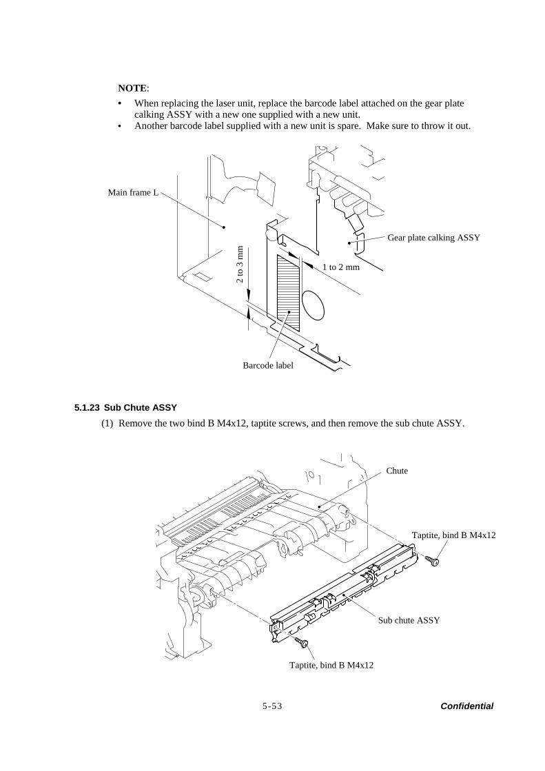
Confidential 5-53
NOTE: • When replacing the laser unit, replace the barcode label attached on the gear plate
calking ASSY with a new one supplied with a new unit. • Another barcode label supplied with a new unit is spare. Make sure to throw it out.
5.1.23 Sub Chute ASSY (1) Remove the two bind B M4x12, taptite screws, and then remove the sub chute ASSY.
Main frame L
Gear plate calking ASSY
1 to 2 mm
Chute
Taptite, bind B M4x12
Sub chute ASSY
Taptite, bind B M4x12
Barcode label
2 to
3 m
m
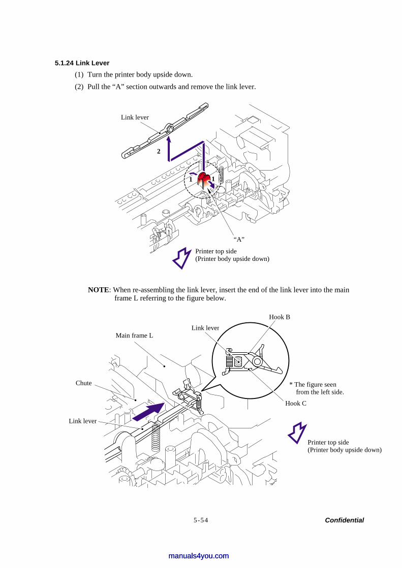
Confidential 5-54
5.1.24 Link Lever (1) Turn the printer body upside down. (2) Pull the “A” section outwards and remove the link lever.
NOTE: When re-assembling the link lever, insert the end of the link lever into the main frame L referring to the figure below.
Link lever
“A”
Printer top side(Printer body upside down)
2
1
Main frame L
Chute
Link lever
Link lever
* The figure seenfrom the left side.
Hook C
Printer top side (Printer body upside down)
Hook B
1
manuals4you.commanuals4you.com
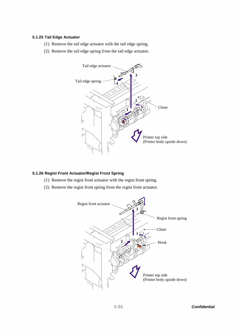
Confidential 5-55
5.1.25 Tail Edge Actuator (1) Remove the tail edge actuator with the tail edge spring. (2) Remove the tail edge spring from the tail edge actuator.
5.1.26 Regist Front Actuator/Regist Front Spring (1) Remove the regist front actuator with the regist front spring. (2) Remove the regist front spring from the regist front actuator.
Tail edge actuator
Tail edge spring
Chute
Printer top side (Printer body upside down)
3
4
1
2
Regist front actuator
Regist front spring
Chute
Hook
Printer top side (Printer body upside down)
1
2
3
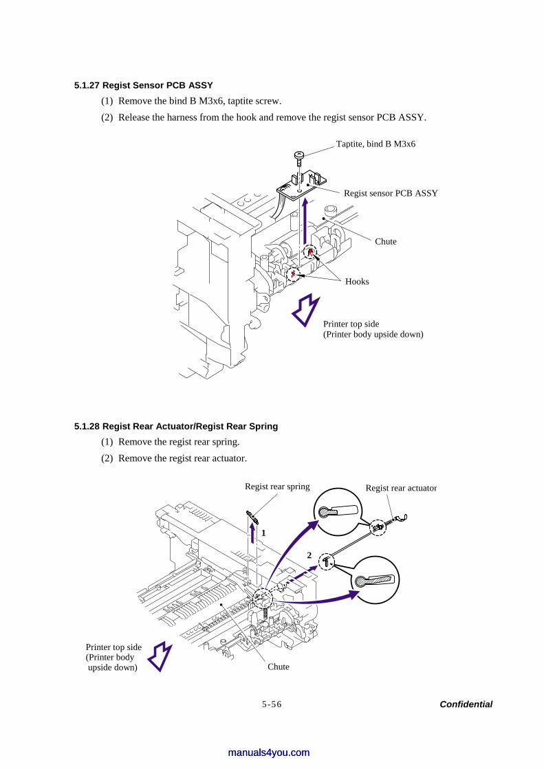
Confidential 5-56
5.1.27 Regist Sensor PCB ASSY (1) Remove the bind B M3x6, taptite screw. (2) Release the harness from the hook and remove the regist sensor PCB ASSY.
5.1.28 Regist Rear Actuator/Regist Rear Spring (1) Remove the regist rear spring. (2) Remove the regist rear actuator.
Taptite, bind B M3x6
Regist sensor PCB ASSY
Chute
Hooks
Printer top side (Printer body upside down)
Regist rear spring Regist rear actuator
Chute
Printer top side (Printer body upside down)
1
2
manuals4you.commanuals4you.com
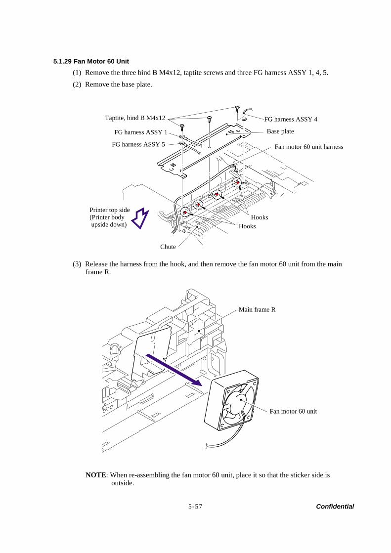
Confidential 5-57
5.1.29 Fan Motor 60 Unit (1) Remove the three bind B M4x12, taptite screws and three FG harness ASSY 1, 4, 5. (2) Remove the base plate.
(3) Release the harness from the hook, and then remove the fan motor 60 unit from the main frame R.
NOTE: When re-assembling the fan motor 60 unit, place it so that the sticker side is outside.
Taptite, bind B M4x12
FG harness ASSY 1
FG harness ASSY 5
FG harness ASSY 4
Base plate
Fan motor 60 unit harness
HooksHooks
Chute
Main frame R
Printer top side (Printer body upside down)
Fan motor 60 unit
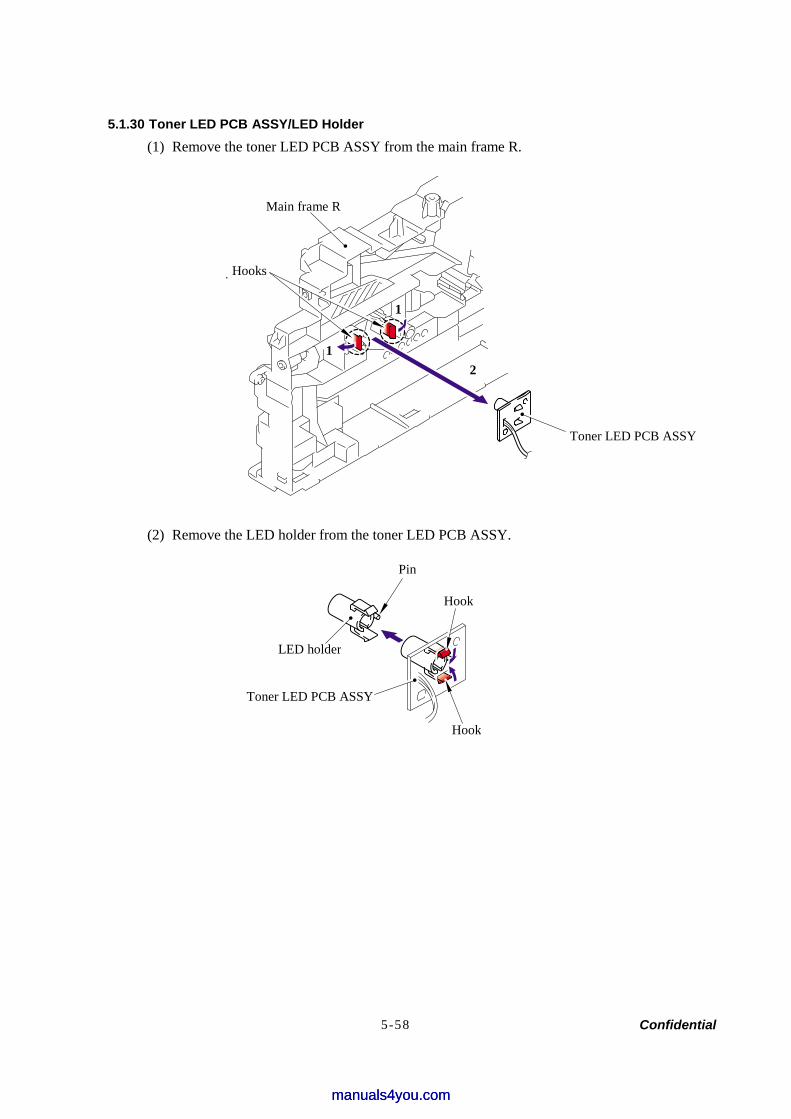
Confidential 5-58
5.1.30 Toner LED PCB ASSY/LED Holder (1) Remove the toner LED PCB ASSY from the main frame R.
(2) Remove the LED holder from the toner LED PCB ASSY.
Toner LED PCB ASSY
21
1
Pin
LED holder
Toner LED PCB ASSY
Hook
Hook
Hooks
Main frame R
manuals4you.commanuals4you.com
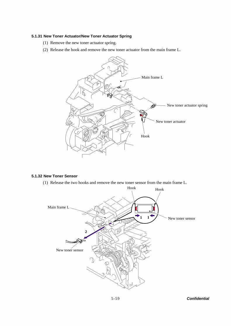
Confidential 5-59
5.1.31 New Toner Actuator/New Toner Actuator Spring (1) Remove the new toner actuator spring. (2) Release the hook and remove the new toner actuator from the main frame L.
5.1.32 New Toner Sensor (1) Release the two hooks and remove the new toner sensor from the main frame L.
Main frame L
New toner actuator spring
New toner actuator
Hook
Hook Hook
Main frame L
New toner sensor
2
New toner sensor 1 1
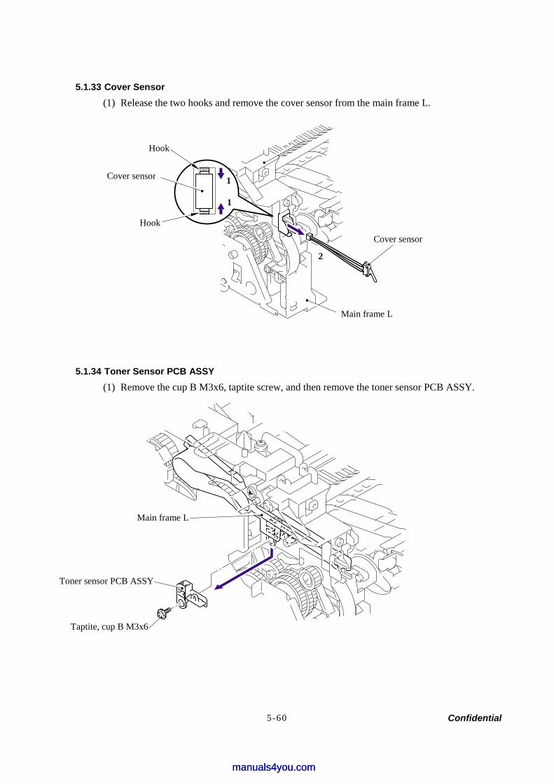
Confidential 5-60
5.1.33 Cover Sensor (1) Release the two hooks and remove the cover sensor from the main frame L.
5.1.34 Toner Sensor PCB ASSY (1) Remove the cup B M3x6, taptite screw, and then remove the toner sensor PCB ASSY.
Hook
Cover sensor
Hook
1
1
Main frame L
Cover sensor
2
Main frame L
Toner sensor PCB ASSY
Taptite, cup B M3x6
manuals4you.commanuals4you.com
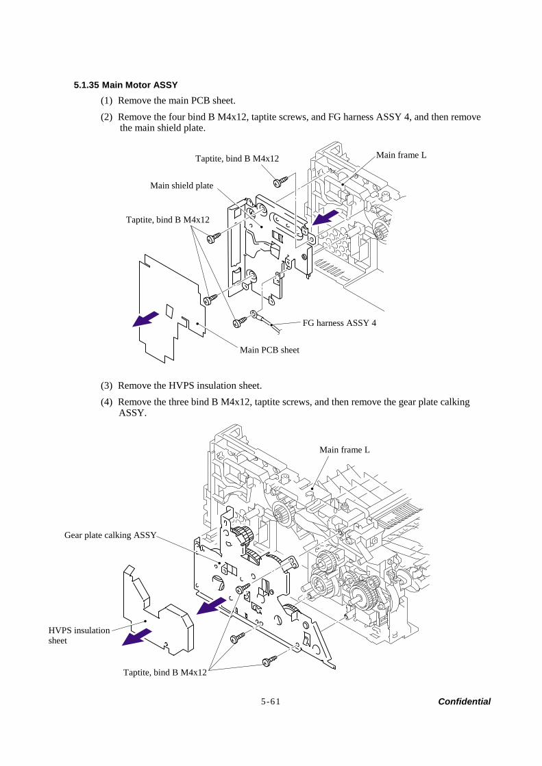
Confidential 5-61
5.1.35 Main Motor ASSY (1) Remove the main PCB sheet. (2) Remove the four bind B M4x12, taptite screws, and FG harness ASSY 4, and then remove
the main shield plate.
(3) Remove the HVPS insulation sheet. (4) Remove the three bind B M4x12, taptite screws, and then remove the gear plate calking
ASSY.
Main frame L
Gear plate calking ASSY
HVPS insulation sheet
Taptite, bind B M4x12
Main shield plate
Main frame L
FG harness ASSY 4
Taptite, bind B M4x12
Main PCB sheet
Taptite, bind B M4x12
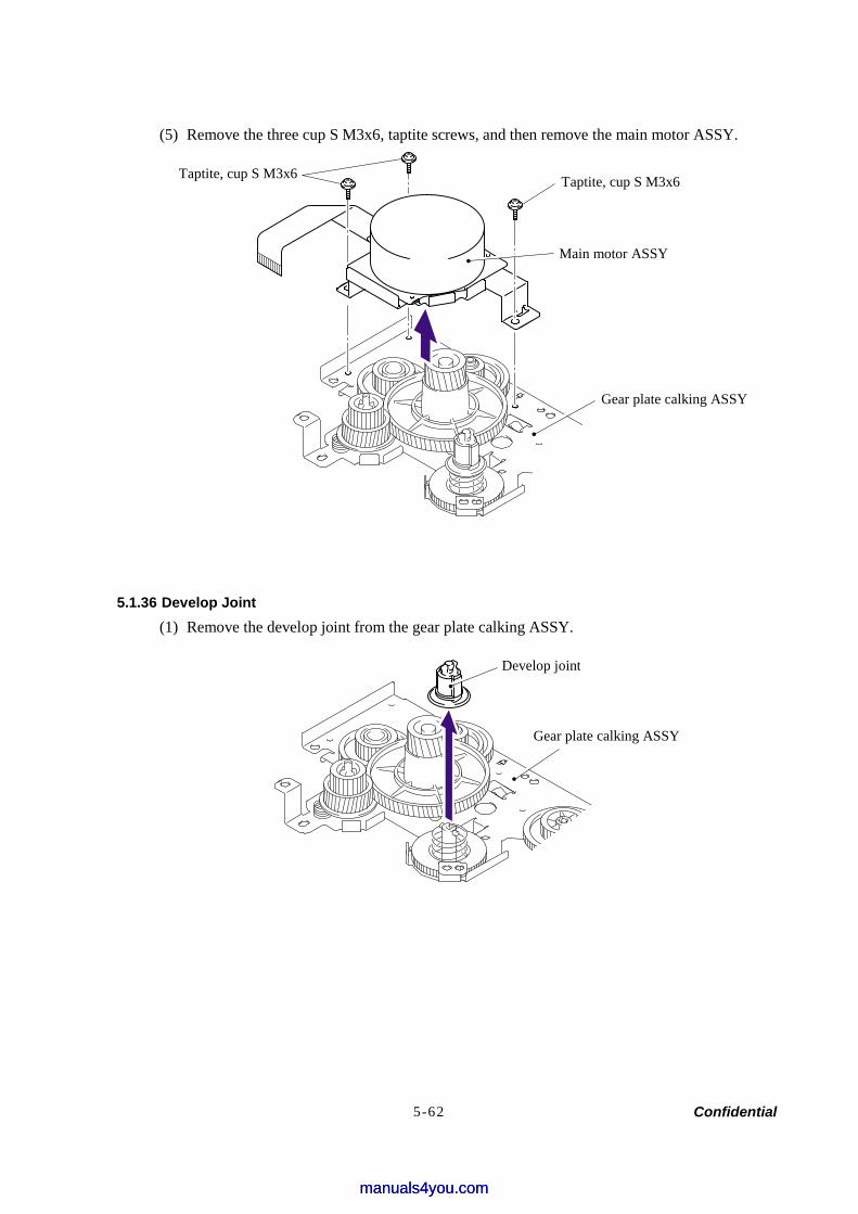
Confidential 5-62
(5) Remove the three cup S M3x6, taptite screws, and then remove the main motor ASSY.
5.1.36 Develop Joint (1) Remove the develop joint from the gear plate calking ASSY.
Taptite, cup S M3x6 Taptite, cup S M3x6
Main motor ASSY
Gear plate calking ASSY
Gear plate calking ASSY
Develop joint
manuals4you.commanuals4you.com
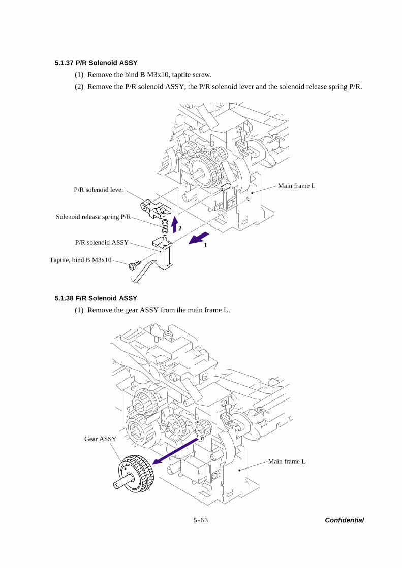
Confidential 5-63
5.1.37 P/R Solenoid ASSY (1) Remove the bind B M3x10, taptite screw. (2) Remove the P/R solenoid ASSY, the P/R solenoid lever and the solenoid release spring P/R.
5.1.38 F/R Solenoid ASSY (1) Remove the gear ASSY from the main frame L.
P/R solenoid lever
Solenoid release spring P/R
P/R solenoid ASSY
Taptite, bind B M3x10
Main frame L
1
2
Gear ASSY
Main frame L

Confidential 5-64
NOTE: The gear ASSY contains the small gears. Be careful not to lose them by disassembling the gear ASSY.
(2) Remove the bind B M3x10, taptite screw. (3) Remove the F/R solenoid ASSY, the F/R solenoid lever and the solenoid release spring F/R.
Gear 40/54 F/R
Gear 45 arm F/R
Gear 17 planetary F/R
F/R solenoid ASSY
Taptite, bind B M3x10
Main frame L
F/R solenoid lever Solenoid release spring F/R
1 2
Gear center F/R
manuals4you.commanuals4you.com
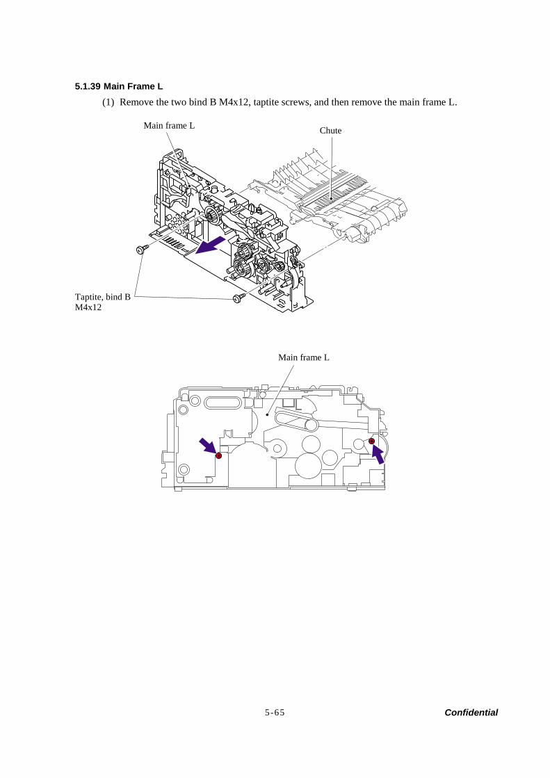
Confidential 5-65
5.1.39 Main Frame L (1) Remove the two bind B M4x12, taptite screws, and then remove the main frame L.
Main frame L Chute
Taptite, bind B M4x12
Main frame L
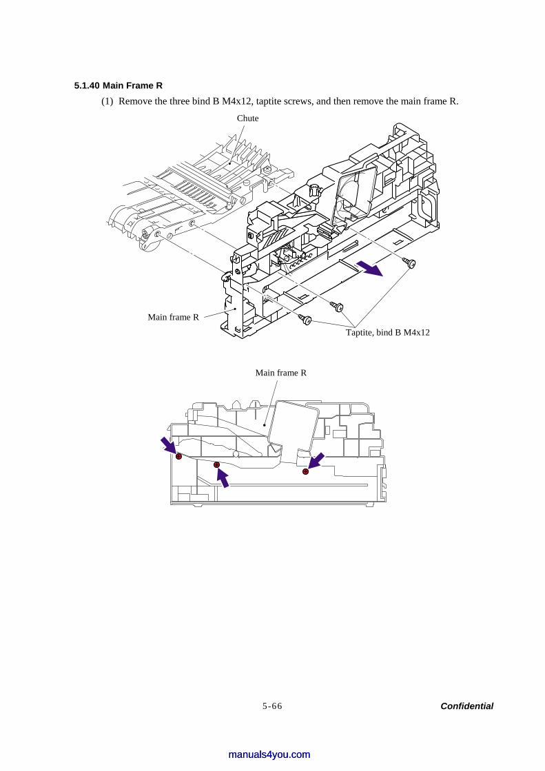
Confidential 5-66
5.1.40 Main Frame R (1) Remove the three bind B M4x12, taptite screws, and then remove the main frame R.
Chute
Main frame R
Taptite, bind B M4x12
Main frame R
manuals4you.commanuals4you.com
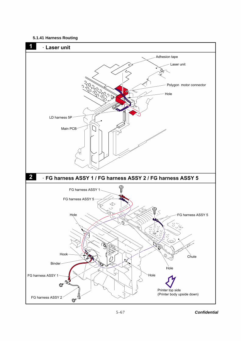
Confidential 5-67
5.1.41 Harness Routing
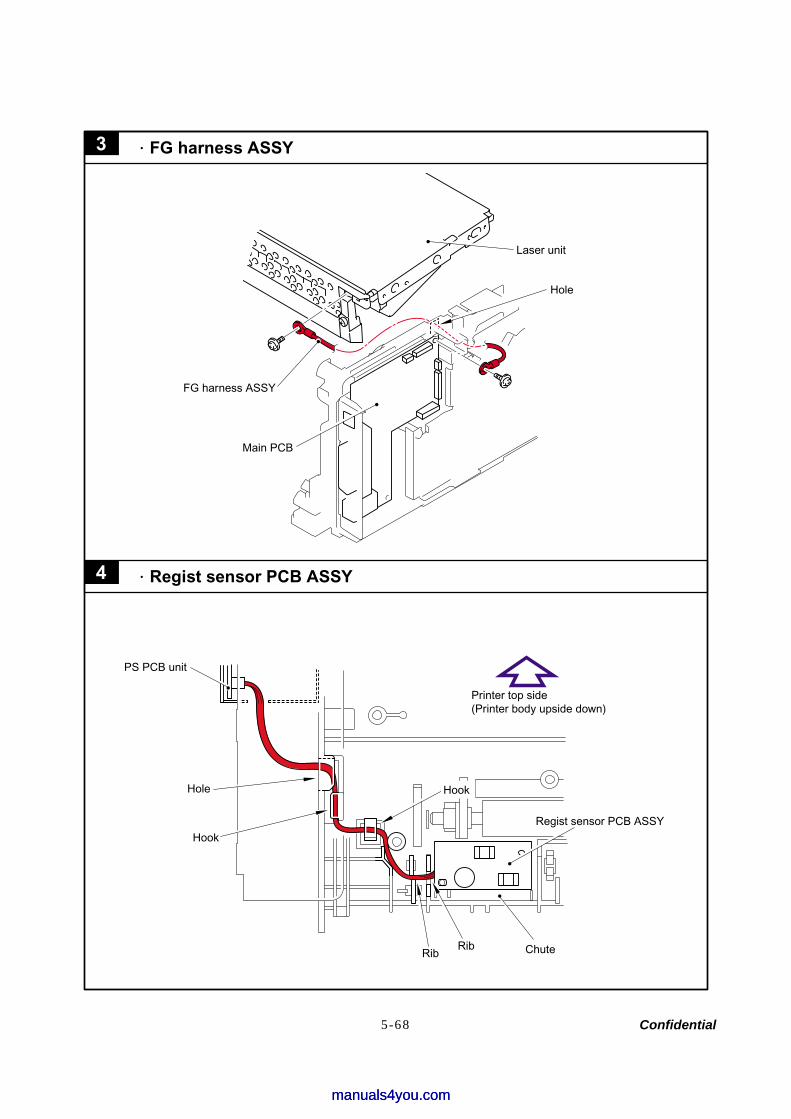
Confidential 5-68
manuals4you.commanuals4you.com
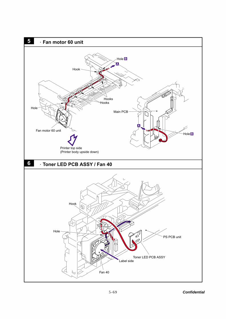
Confidential 5-69
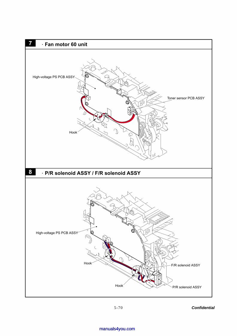
Confidential 5-70
manuals4you.commanuals4you.com
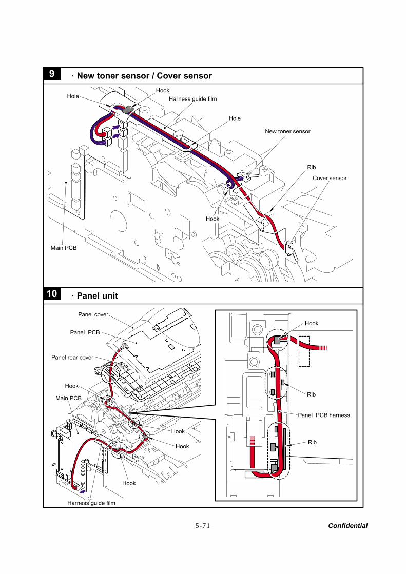
Confidential 5-71
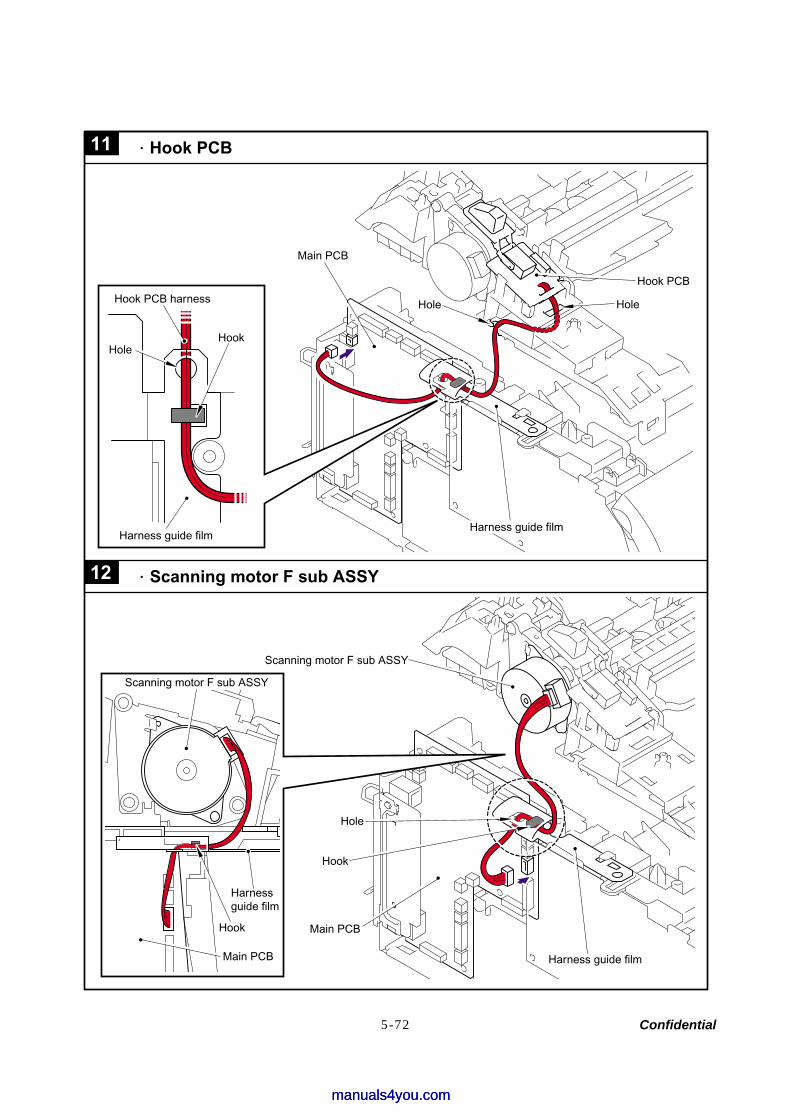
Confidential 5-72
manuals4you.commanuals4you.com
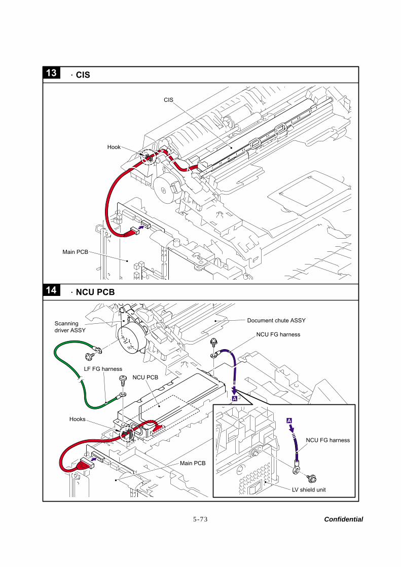
Confidential 5-73
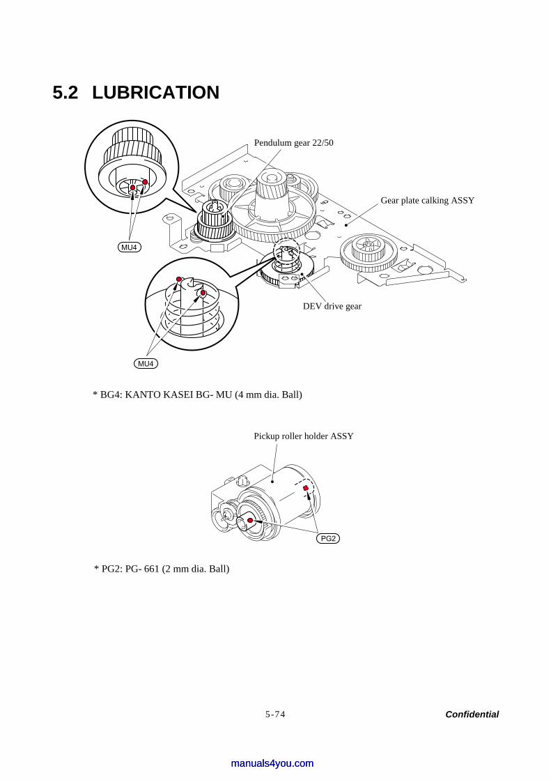
Confidential 5-74
5.2 LUBRICATION
MU4
MU4
* BG4: KANTO KASEI BG- MU (4 mm dia. Ball)
PG2
* PG2: PG- 661 (2 mm dia. Ball)
DEV drive gear
Gear plate calking ASSY
Pendulum gear 22/50
Pickup roller holder ASSY
manuals4you.commanuals4you.com
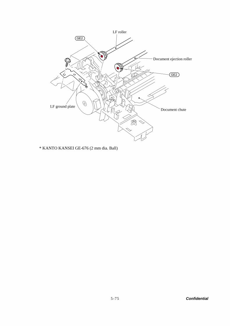
Confidential 5-75
GE2
GE2
* KANTO KANSEI GE-676 (2 mm dia. Ball)
LF roller
Document ejection roller
Document chuteLF ground plate
Confidential
CHAPTER 6ADJUSTMENTS AND UPDATING OF SETTINGS,
REQUIRED AFTER PARTS REPLACEMENT
manuals4you.commanuals4you.com
Confidential
CHAPTER 6 ADJUSTMENTS AND UPDATING OF SETTINGS, REQUIRED AFTER PARTS REPLACEMENT
This chapter details adjustments and updating of settings, which are required if main PCB and some other parts have been replaced.
CONTENTS
6.1 IF YOU REPLACE THE MAIN PCB.................................................................................6-1
[ 1 ] Load update programs/data.........................................................................6-1
[ 2 ] Initialize the EEPROM on the main PCB (Function code 01) ......................6-1
[ 3 ] Customize the EEPROM on the main PCB (Function code 74) ..................6-1
[ 4 ] Check the control panel PCB for normal operation (Function code 13) ......6-1
[ 5 ] Adjust the handset volume (Function code 16)............................................6-1
[ 6 ] Make a sensor operation check (Function code 32)....................................6-1
[ 7 ] Adjust the scan start/end positions (Function code 54) ...............................6-1
[ 8 ] Acquire of white level data and set the CIS scanner area (Function code 55) .......................................................................................6-1
[ 9 ] Setting the serial number .............................................................................6-1
[ 10 ] Inputting the adjusted value of the laser scanner ........................................6-1
[ 11 ] Switch back to standby ................................................................................6-1
6.2 IF YOU REPLACE THE CIS ............................................................................................6-2
6.3 IF YOU REPLACE THE LASER UNIT.............................................................................6-2

6-1 Confidential
6.1 IF YOU REPLACE THE MAIN PCB NOTE: If you replace the main PCB, also replace the ink absorber box. Using the machine
without replacing the ink absorber box may cause an overflow of drained ink from the ink absorber box, thereby staining the machine.
[ 1 ] Load update program/data
If the main PCB is replaced with a new one, write the update program/data onto the flash ROM. Refer to Appendix 2, page App. 2-2.
[ 2 ] Initialize the EEPROM on the main PCB (Function code 01)
Refer to Chapter 8, Section 8.4.1.
[ 3 ] Customize the EEPROM on the main PCB (Function code 74)
Refer to Chapter 8, Section 8.4.14.
[ 4 ] Check the control panel PCB for normal operation (Function code 13)
Refer to Chapter 8, Section 8.4.7.
[ 5 ] Adjust the handset volume (Function code 16)
Refer to Chapter 8, Section 8.4.8.
[ 6 ] Make a sensor operation check (Function code 32)
Refer to Chapter 8, Section 8.4.9.
[ 7 ] Adjust the scan start/end positions (Function code 54)
Refer to Chapter 8, Section 8.4.11.
[ 8 ] Acquire of white level data and set the CIS scanner area Setting (Function code 55)
Refer to Chapter 8, Section 8.4.12.
[ 9 ] Setting the serial number (1) Double-click the brmainte.EXE file (maintenance utility). (2) Select Input Information from Menu. Select the applicable model name. (3) Check the port (USB) which the printer is connected through and click “Serial No.” in
the lower box. Enter the serial number (the last nine digits) of the printer into the box at the right hand side and click the OK button. The serial number is shown in the window, and check that it is correct. The setting of the serial number is completed.
[ 10 ] Inputting the adjusted value of the laser scanner
Select ‘Adjust Scanner’ from Menu. Enter the figures (the last four digits) shown on the label attached on the chassis at the right hand side of the main PCB into the box at the right hand side, and click the OK button.
[ 11 ] Switch back to standby
Disconnect the USB cable and press the 9 key twice.
manuals4you.commanuals4you.com
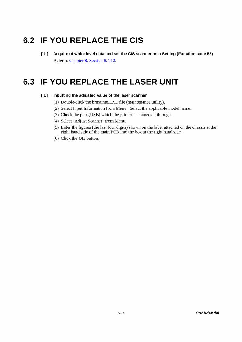
6-2 Confidential
6.2 IF YOU REPLACE THE CIS [ 1 ] Acquire of white level data and set the CIS scanner area Setting (Function code 55)
Refer to Chapter 8, Section 8.4.12.
6.3 IF YOU REPLACE THE LASER UNIT [ 1 ] Inputting the adjusted value of the laser scanner
(1) Double-click the brmainte.EXE file (maintenance utility). (2) Select Input Information from Menu. Select the applicable model name. (3) Check the port (USB) which the printer is connected through. (4) Select ‘Adjust Scanner’ from Menu. (5) Enter the figures (the last four digits) shown on the label attached on the chassis at the
right hand side of the main PCB into the box at the right hand side. (6) Click the OK button.

Confidential
CHAPTER 7CLEANING
manuals4you.commanuals4you.com

Confidential
CHAPTER 7 CLEANING
For the cleaning procedures of the drum unit and toner cartridge, refer to the User's Guide.

Confidential
CHAPTER 8MAINTENANCE MODE
manuals4you.commanuals4you.com
Confidential
CHAPTER 8 MAINTENANCE MODE
This chapter describes the maintenance mode which is exclusively designed for the purpose of checks, settings and adjustments using the keys on the control panel. You can customize the EEPROM according to the shipment destination of the machine concerned. In addition, you can perform operational checks of the LCD, control panel PCB or sensors, perform a print test, display the log information or error codes, and modify firmware switches (WSW).
CONTENTS
8.1 ENTRY INTO THE MAINTENANCE MODE ....................................................................8-1
8.2 LIST OF MAINTENANCE-MODE FUNCTIONS ..............................................................8-2
8.3 USER-ACCESS TO THE MAINTENANCE MODE..........................................................8-3
8.4 DETAILED DESCRIPTION OF MAINTENANCE-MODE FUNCTIONS ..........................8-5
8.4.1 EEPROM Parameter Initialization (Function code 01/91) ....................................8-5
8.4.2 Printout of Scanning Compensation Data (Function code 05) .............................8-6
8.4.3 ADF Performance Test (Function mode 08) ........................................................8-8
8.4.4 Test Pattern (Function mode 09) .........................................................................8-9
8.4.5 Firmware Switch Setting and Printout ................................................................8-10 8.4.5.1 Firmware switch setting (Function mode 10) .............................................8-10
8.4.5.2 Printout of firmware switch data (Function mode 11).................................8-12 8.4.6 Operation Check of LCD (Function mode 12)....................................................8-13
8.4.7 Operational Check of Control Panel PCB (Function mode 13) ..........................8-14
8.4.8 Adjustment of Handset Volume (Function code 16) ..........................................8-15
8.4.9 Sensor Operational Check (Function mode 32).................................................8-16
8.4.10 Received Data Transfer Function (Function mode 53) ......................................8-17
8.4.11 Fine Adjustment of Scan Start/End Positions (Function mode 54) ....................8-19
8.4.12 Acquisition of White Level Data and CIS Scanner Area Setting (Function mode 55) ............................................................................................8-21
8.4.13 Continuous print Test (Function mode 67).........................................................8-21
8.4.14 EEPROM Customizing (Function mode 74).......................................................8-22
8.4.15 Display of the Equipment’s Log Information (Function mode 80) ......................8-23
8.4.16 Machine Error Code Indication (Function mode 82) ..........................................8-25
8.4.17 Output of Transmission Log to the Telephone Line (Function mode 87)...........8-25
8.4.18 Cancellation of the Memory Security Mode........................................................8-25

8-1 Confidential
8.1 ENTRY INTO THE MAINTENANCE MODE
Press the Menu/Set and Start keys. Next press the key four times to make the machine enter the maintenance mode.
TIP: FAX models equipped with numerical keypads can enter the maintenance mode in the same way as conventional models; that is, by pressing the Menu/Set, *, 2, 8, 6 and 4 keys in this sequence.
The machine beeps for approx. one second and displays " " on the LCD, indicating that it is placed in the initial stage of the maintenance mode, a mode in which the machine is ready to accept entry from the keys.
To select one of the maintenance-mode functions listed in Section 8.2, enter the corresponding 2-digit function code with the numerical keys on the control panel. (The details of each maintenance-mode function are described in Section 8.4.)
NOTE: • To exit from the maintenance mode and switch to standby, press the 9 key twice in the initial
stage of the maintenance mode. • Pressing the Stop/Exit key after entering only one digit restores the machine to the initial stage
of the maintenance mode. • If an invalid function code is entered, the machine resumes the initial stage of the maintenance
mode.
manuals4you.commanuals4you.com

8-2 Confidential
8.2 LIST OF MAINTENANCE-MODE FUNCTIONS Maintenance-mode Functions
Function Code Function Reference
Section (Page)
01 EEPROM Parameter Initialization 8.4.1 (8-5)
05 Printout of Scanning Compensation Data 8.4.2 (8-6)
08 ADF Performance Test 8.4.3 (8-8)
09 Test Pattern 8.4.4 (8-9)
10 Firmware Switch Setting 8.4.5.1 (8-10)
11 Printout of Firmware Switch Data 8.4.5.2 (8-12)
12 Operational Check of LCD 8.4.6 (8-13)
13 Operational Check of Control Panel PCB 8.4.7 (8-14)
16 Adjustment of Handset Volume 8.4.8 (8-15)
32 Sensor Operational Check 8.4.9 (8-16)
53 Received Data Transfer Function 8.4.10 (8-17)
54 Fine Adjustment of Scan Start/End Positions 8.4.11 (8-19)
55 Acquisition of White Level Data and CIS Scanner Area Setting 8.4.12 (8-21)
67 Continuous print Test 8.4.13 (8-21)
74 EEPROM Customizing 8.4.14 (8-22)
80 Display of the Equipment’s Log Information 8.4.15 (8-23)
82 Machine Error Code Indication 8.4.16 (8-25)
87 Output of Transmission Log to the Telephone Line 8.4.17 (8-25)
99 Exit from the Maintenance Mode
Cancellation of the Memory Security Mode 8.4.18 (8-25)
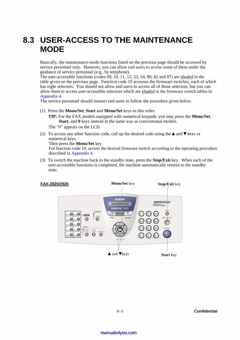
8-3 Confidential
8.3 USER-ACCESS TO THE MAINTENANCE MODE Basically, the maintenance-mode functions listed on the previous page should be accessed by service personnel only. However, you can allow end users to access some of these under the guidance of service personnel (e.g., by telephone). The user-accessible functions (codes 09, 10, 11, 12, 53, 54, 80, 82 and 87) are shaded in the table given on the previous page. Function code 10 accesses the firmware switches, each of which has eight selectors. You should not allow end users to access all of those selectors, but you can allow them to access user-accessible selectors which are shaded in the firmware switch tables in Appendix 4. The service personnel should instruct end users to follow the procedure given below. (1) Press the Menu/Set, Start and Menu/Set keys in this order.
TIP: For the FAX models equipped with numerical keypads, you may press the Menu/Set, Start, and 0 keys instead in the same way as conventional models.
The "0" appears on the LCD. (2) To access any other function code, call up the desired code using the and keys or
numerical keys. Then press the Menu/Set key. For function code 10, access the desired firmware switch according to the operating procedure described in Appendix 4.
(3) To switch the machine back to the standby state, press the Stop/Exit key. When each of the user-accessible functions is completed, the machine automatically returns to the standby state.
FAX-2820/2920
Stop/Exit key Menu/Set key
and keys Start key
manuals4you.commanuals4you.com
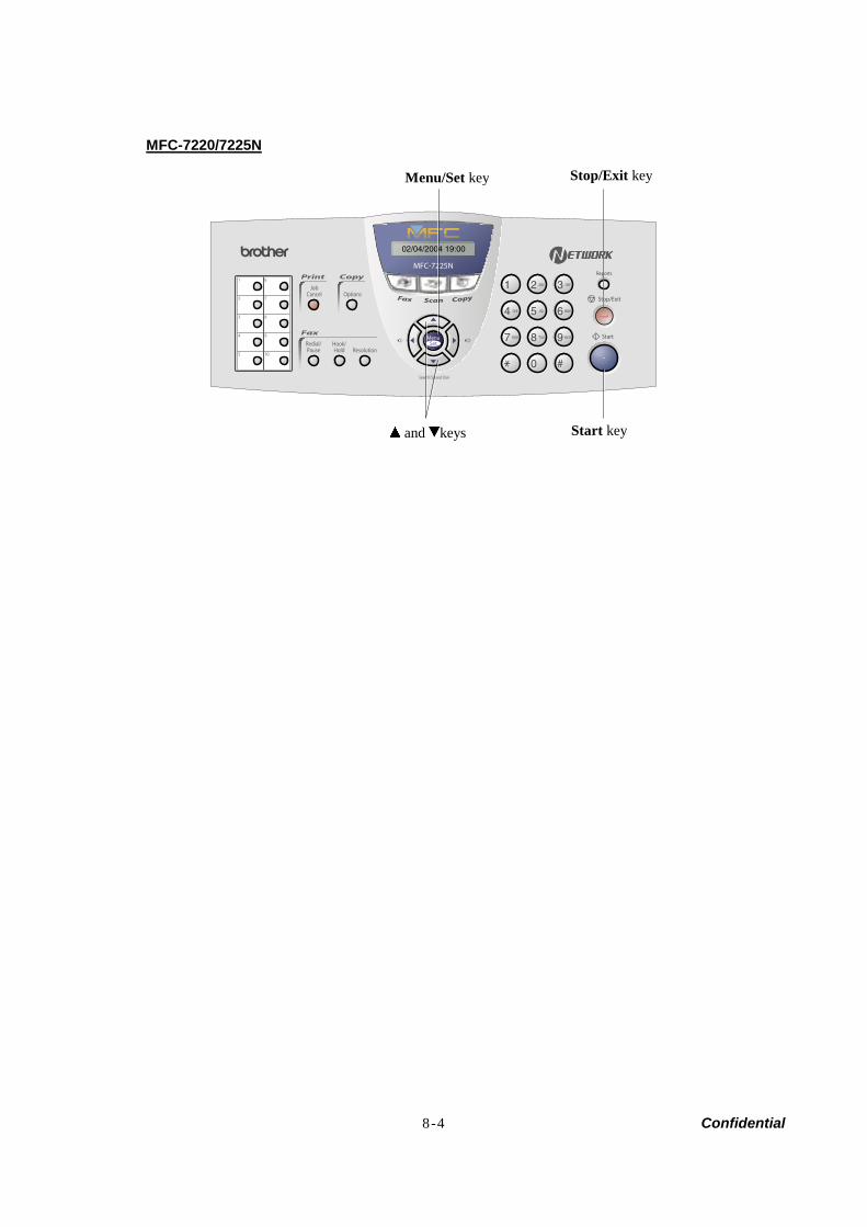
8-4 Confidential
MFC-7220/7225N
Menu/Set key
and keys Start key
Stop/Exit key
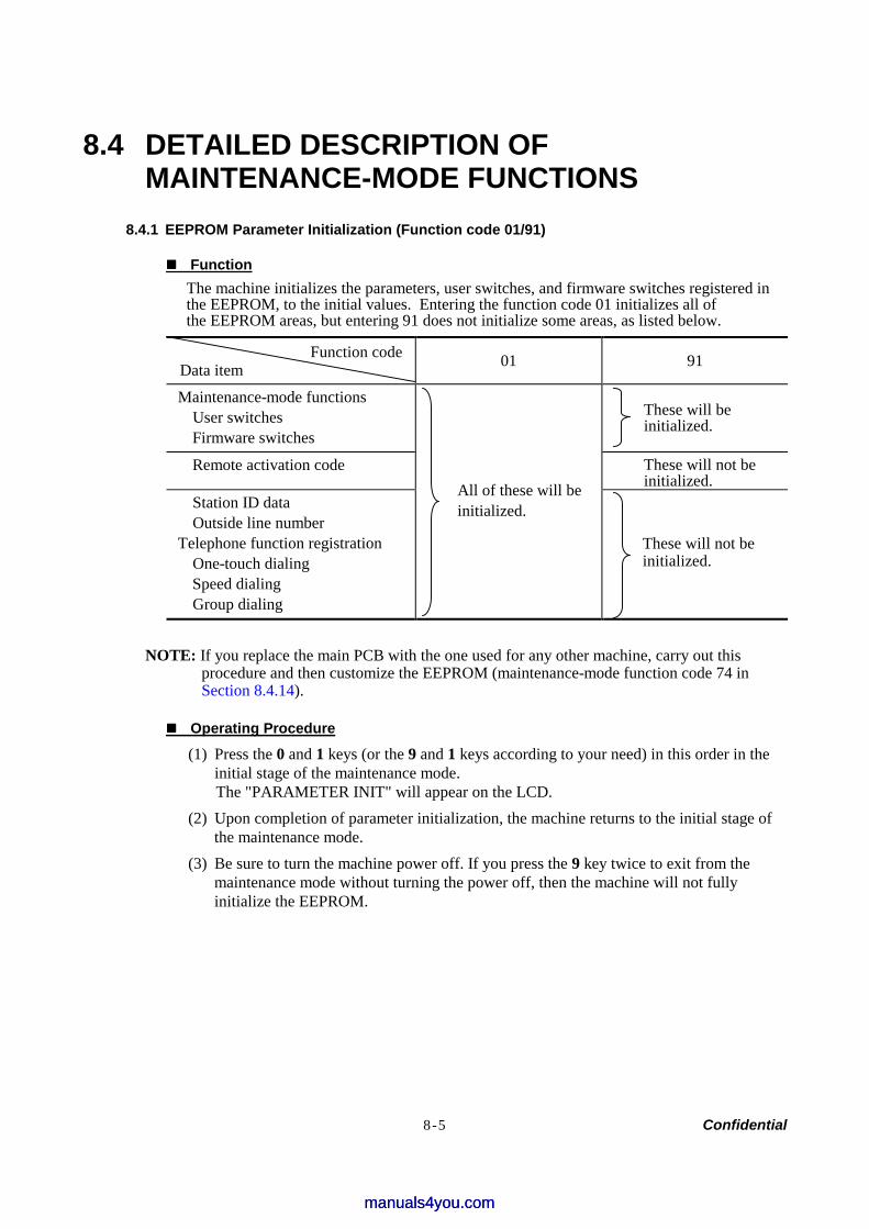
8-5 Confidential
8.4 DETAILED DESCRIPTION OF MAINTENANCE-MODE FUNCTIONS
8.4.1 EEPROM Parameter Initialization (Function code 01/91)
Function The machine initializes the parameters, user switches, and firmware switches registered in the EEPROM, to the initial values. Entering the function code 01 initializes all of the EEPROM areas, but entering 91 does not initialize some areas, as listed below.
Function code Data item 01 91
Maintenance-mode functions User switches Firmware switches
These will be initialized.
Remote activation code These will not be initialized.
Station ID data Outside line number
Telephone function registration One-touch dialing Speed dialing Group dialing
All of these will be initialized.
These will not be initialized.
NOTE: If you replace the main PCB with the one used for any other machine, carry out this
procedure and then customize the EEPROM (maintenance-mode function code 74 in Section 8.4.14).
Operating Procedure
(1) Press the 0 and 1 keys (or the 9 and 1 keys according to your need) in this order in the initial stage of the maintenance mode. The "PARAMETER INIT" will appear on the LCD.
(2) Upon completion of parameter initialization, the machine returns to the initial stage of the maintenance mode.
(3) Be sure to turn the machine power off. If you press the 9 key twice to exit from the maintenance mode without turning the power off, then the machine will not fully initialize the EEPROM.
manuals4you.commanuals4you.com
8-6 Confidential
8.4.2 Printout of Scanning Compensation Data (Function code 05)
Function The machine prints out the white and black level data for scanning compensation.
Operating Procedure Do not start this function merely after powering on the equipment but start it after carrying out a sequence of scanning operation. Unless the equipment has carried out any scanning operation, this function cannot print out correct scanning compensation data. This is because at the start of scanning operation, the equipment initializes white and black level data and takes in the scanning compensation reference data. (1) Press the 0 and 5 keys in this order in the initial stage of the maintenance mode.
The "WHITE LEVEL 1" will appear on the LCD. (2) The equipment prints out the scanning compensation data list containing the following:
a) Bright output adjustment value 1Byte b) Illuminant adjustment value 1Byte c) Black level MIN data 1Byte d) Black level MAX data 1Byte e) White level MIN data 1Byte f) White level MAX data 1Byte g) Background color compensated data 1Byte h) Black level data 1664Byte i) White level data 1664Byte
(3) Upon completion of recording of the compensation data list, the equipment returns to the initial stage of the maintenance mode.
NOTE: If any data is abnormal, its code will be printed in inline style, as shown on the next page.
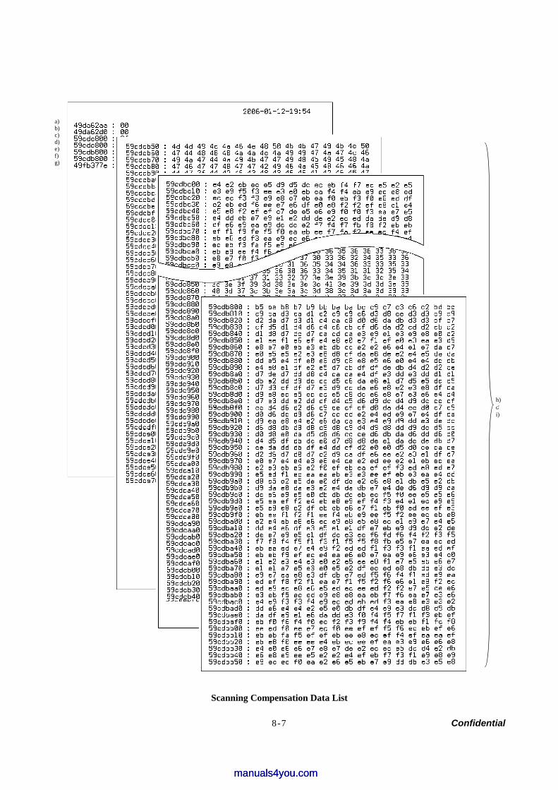
8-7 Confidential
Scanning Compensation Data List
a) b) c) d) e) f) g)
h) | i)
manuals4you.commanuals4you.com
8-8 Confidential
8.4.3 ADF Performance Test (Function code 08)
Function The machine counts the documents fed by the automatic document feeder (ADF) and displays the count on the LCD for checking the ADF performance.
Operating Procedure
(1) Set documents. (Allowable up to the ADF capacity.) The "DOC. READY" will appear on the LCD.
(2) Press the 0 and 8 keys in this order. While counting the documents, the machine feeds them in and out, displaying the current count on the LCD as shown below.
Current count (1st page in this example)
(3) To return the machine to the initial stage of the maintenance mode, press the Stop/Exit key.
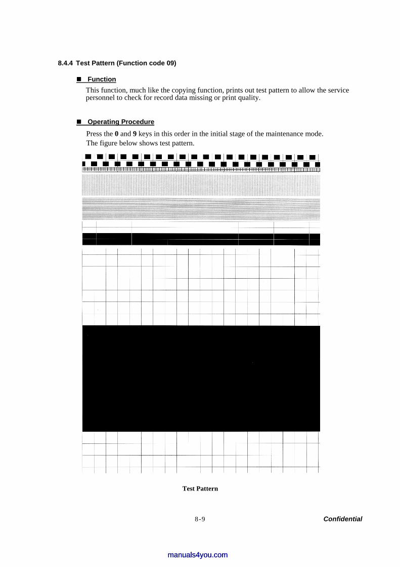
8-9 Confidential
8.4.4 Test Pattern (Function code 09)
Function This function, much like the copying function, prints out test pattern to allow the service personnel to check for record data missing or print quality.
Operating Procedure
Press the 0 and 9 keys in this order in the initial stage of the maintenance mode. The figure below shows test pattern.
Test Pattern
manuals4you.commanuals4you.com
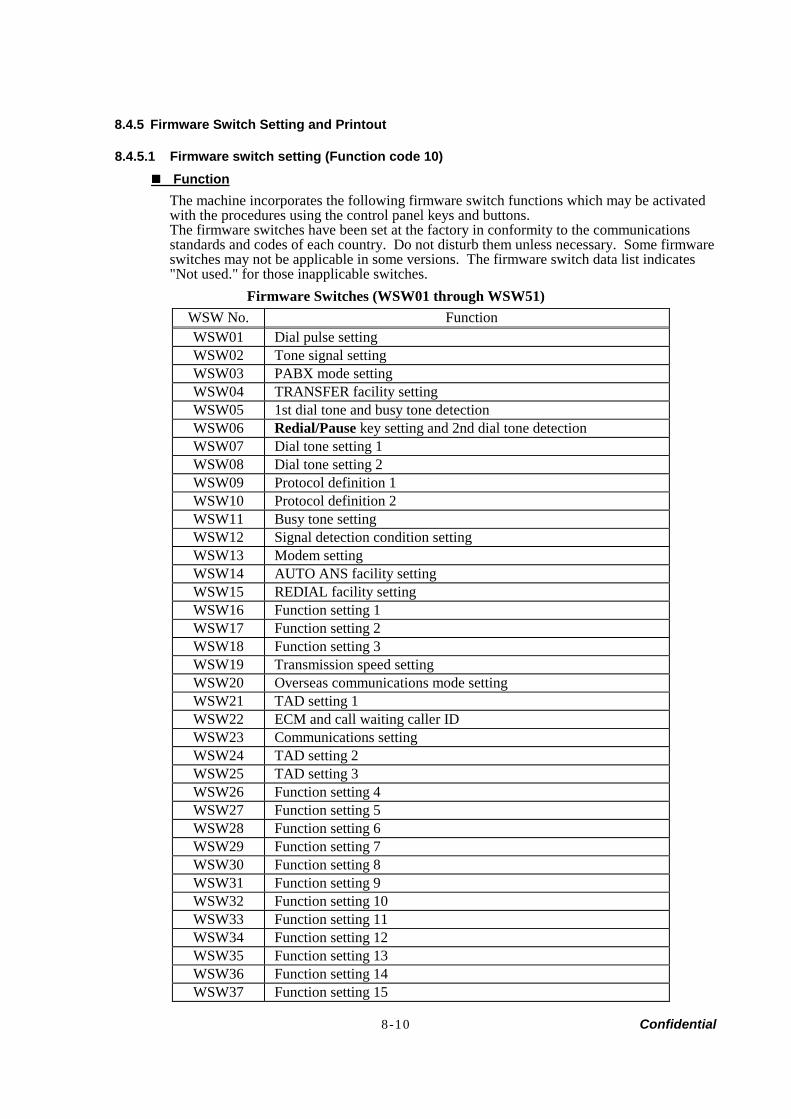
8-10 Confidential
8.4.5 Firmware Switch Setting and Printout
8.4.5.1 Firmware switch setting (Function code 10) Function
The machine incorporates the following firmware switch functions which may be activated with the procedures using the control panel keys and buttons. The firmware switches have been set at the factory in conformity to the communications standards and codes of each country. Do not disturb them unless necessary. Some firmware switches may not be applicable in some versions. The firmware switch data list indicates "Not used." for those inapplicable switches.
Firmware Switches (WSW01 through WSW51) WSW No. Function WSW01 Dial pulse setting WSW02 Tone signal setting WSW03 PABX mode setting WSW04 TRANSFER facility setting WSW05 1st dial tone and busy tone detection WSW06 Redial/Pause key setting and 2nd dial tone detection WSW07 Dial tone setting 1 WSW08 Dial tone setting 2 WSW09 Protocol definition 1 WSW10 Protocol definition 2 WSW11 Busy tone setting WSW12 Signal detection condition setting WSW13 Modem setting WSW14 AUTO ANS facility setting WSW15 REDIAL facility setting WSW16 Function setting 1 WSW17 Function setting 2 WSW18 Function setting 3 WSW19 Transmission speed setting WSW20 Overseas communications mode setting WSW21 TAD setting 1 WSW22 ECM and call waiting caller ID WSW23 Communications setting WSW24 TAD setting 2 WSW25 TAD setting 3 WSW26 Function setting 4 WSW27 Function setting 5 WSW28 Function setting 6 WSW29 Function setting 7 WSW30 Function setting 8 WSW31 Function setting 9 WSW32 Function setting 10 WSW33 Function setting 11 WSW34 Function setting 12 WSW35 Function setting 13 WSW36 Function setting 14 WSW37 Function setting 15
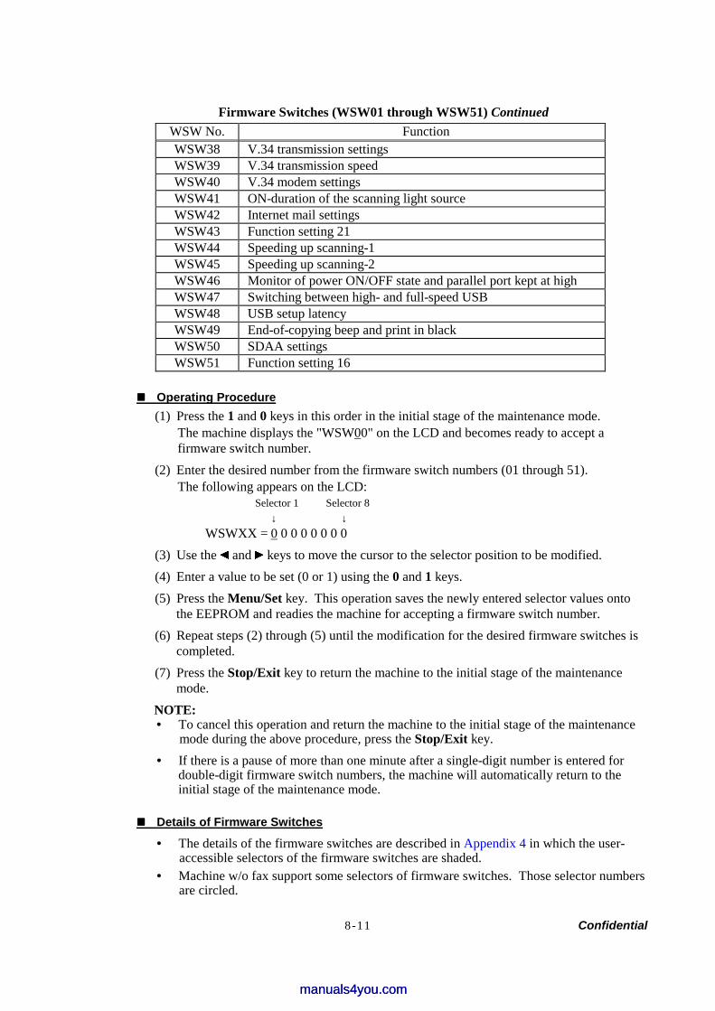
8-11 Confidential
Firmware Switches (WSW01 through WSW51) Continued WSW No. Function WSW38 V.34 transmission settings WSW39 V.34 transmission speed WSW40 V.34 modem settings WSW41 ON-duration of the scanning light source WSW42 Internet mail settings WSW43 Function setting 21 WSW44 Speeding up scanning-1 WSW45 Speeding up scanning-2 WSW46 Monitor of power ON/OFF state and parallel port kept at high WSW47 Switching between high- and full-speed USB WSW48 USB setup latency WSW49 End-of-copying beep and print in black WSW50 SDAA settings WSW51 Function setting 16
Operating Procedure (1) Press the 1 and 0 keys in this order in the initial stage of the maintenance mode.
The machine displays the "WSW00" on the LCD and becomes ready to accept a firmware switch number.
(2) Enter the desired number from the firmware switch numbers (01 through 51). The following appears on the LCD:
Selector 1 Selector 8 ↓ ↓
WSWXX = 0 0 0 0 0 0 0 0 (3) Use the and keys to move the cursor to the selector position to be modified. (4) Enter a value to be set (0 or 1) using the 0 and 1 keys. (5) Press the Menu/Set key. This operation saves the newly entered selector values onto
the EEPROM and readies the machine for accepting a firmware switch number. (6) Repeat steps (2) through (5) until the modification for the desired firmware switches is
completed. (7) Press the Stop/Exit key to return the machine to the initial stage of the maintenance
mode. NOTE: • To cancel this operation and return the machine to the initial stage of the maintenance
mode during the above procedure, press the Stop/Exit key. • If there is a pause of more than one minute after a single-digit number is entered for
double-digit firmware switch numbers, the machine will automatically return to the initial stage of the maintenance mode.
Details of Firmware Switches
• The details of the firmware switches are described in Appendix 4 in which the user- accessible selectors of the firmware switches are shaded.
• Machine w/o fax support some selectors of firmware switches. Those selector numbers are circled.
manuals4you.commanuals4you.com
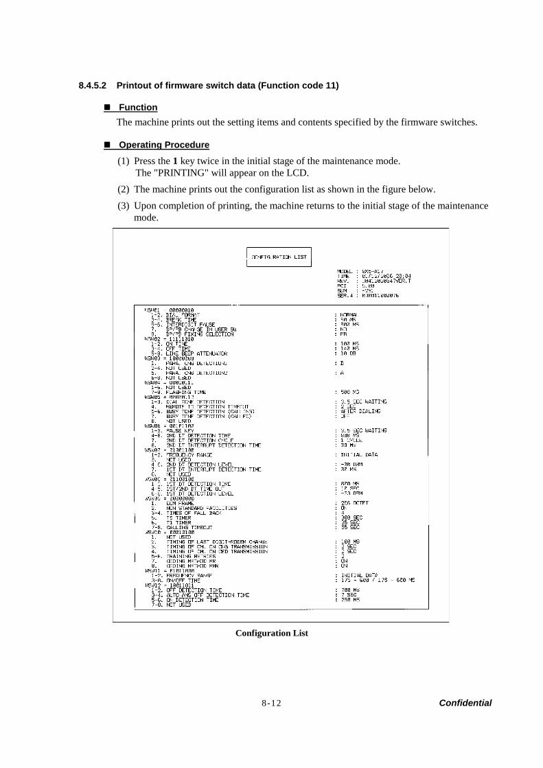
8-12 Confidential
8.4.5.2 Printout of firmware switch data (Function code 11)
Function The machine prints out the setting items and contents specified by the firmware switches.
Operating Procedure
(1) Press the 1 key twice in the initial stage of the maintenance mode. The "PRINTING" will appear on the LCD.
(2) The machine prints out the configuration list as shown in the figure below. (3) Upon completion of printing, the machine returns to the initial stage of the maintenance
mode.
Configuration List
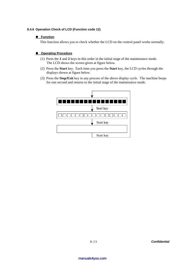
8-13 Confidential
8.4.6 Operation Check of LCD (Function code 12)
Function This function allows you to check whether the LCD on the control panel works normally.
Operating Procedure
(1) Press the 1 and 2 keys in this order in the initial stage of the maintenance mode. The LCD shows the screen given at figure below.
(2) Press the Start key. Each time you press the Start key, the LCD cycles through the displays shown at figure below.
(3) Press the Stop/Exit key in any process of the above display cycle. The machine beeps for one second and returns to the initial stage of the maintenance mode.
manuals4you.commanuals4you.com

8-14 Confidential
8.4.7 Operational Check of Control Panel PCB (Function code 13)
Function This function allows you to check the control panel PCB for normal operation.
Operating Procedure
(1) Press the 1 and 3 keys in this order in the initial stage of the maintenance mode. The "00 " will appear on the LCD.
(2) Press the keys and buttons in the order designated in the illustration shown below. The LCD shows the corresponding number in decimal notation each time a key or button is pressed. Check that the displayed number is correct by referring to the illustration below. If a key or button is pressed out of order, the machine beeps and displays the "INVALID OPERATE" on the LCD. To return to the status ready to accept key & button entry for operational check, press the Stop/Exit key.
(3) After the last number key or button is pressed, the machine beeps for one second and returns to the initial stage of the maintenance mode. To terminate this operation, press the Stop/Exit key. The machine returns to the initial stage of the maintenance mode.
FAX-2820/2920
1
2
3
4
5
6
7
8
9
10
11 12
13 14 15
16 17
18
19
21
23 24 25
26 27 28
29 30 31
32 33 34
35
36
37
20 22
MFC-7220/7225N

8-15 Confidential
8.4.8 Adjustment of Handset Volume (Function code 16)
Function This function allows you to adjust the handset volume when it is too low or high.
Operating Procedure
(1) Press the 1 and 6 keys in this order in the initial stage of the maintenance mode. The “Low HIGH” will appear on the LCD.
(2) Press the key or key. When the key is pressed, the marks indicated on the LCD close with HIGH, and the handset volume is higher. When the key is pressed, the marks indicated on the LCD close with LOW, and the handset volume is lower.
(3) When adjusting the handset volume appropriately, press the Stop/Exit key. The machine will write the adjusted level onto the ROM and return to the initial stage of the maintenance mode.
manuals4you.commanuals4you.com
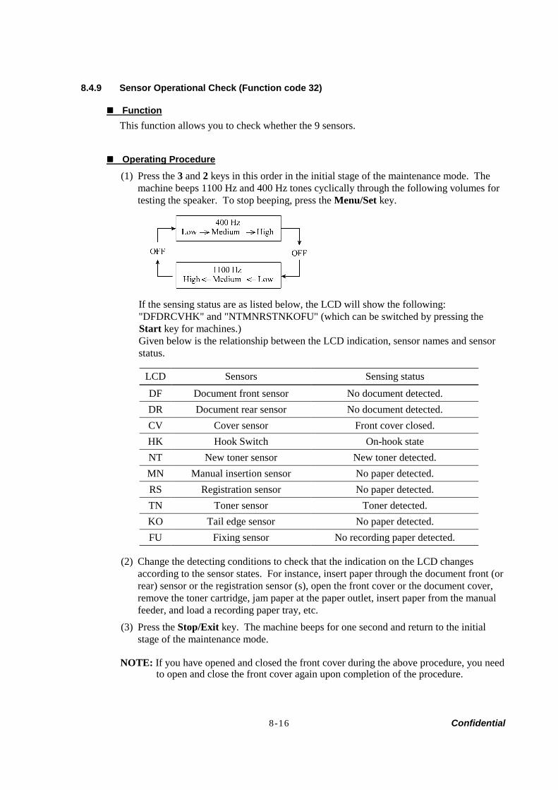
8-16 Confidential
8.4.9 Sensor Operational Check (Function code 32)
Function This function allows you to check whether the 9 sensors.
Operating Procedure
(1) Press the 3 and 2 keys in this order in the initial stage of the maintenance mode. The machine beeps 1100 Hz and 400 Hz tones cyclically through the following volumes for testing the speaker. To stop beeping, press the Menu/Set key.
If the sensing status are as listed below, the LCD will show the following: "DFDRCVHK" and "NTMNRSTNKOFU" (which can be switched by pressing the Start key for machines.) Given below is the relationship between the LCD indication, sensor names and sensor status.
LCD Sensors Sensing status
DF Document front sensor No document detected. DR Document rear sensor No document detected. CV Cover sensor Front cover closed. HK Hook Switch On-hook state NT New toner sensor New toner detected. MN Manual insertion sensor No paper detected. RS Registration sensor No paper detected. TN Toner sensor Toner detected. KO Tail edge sensor No paper detected. FU Fixing sensor No recording paper detected.
(2) Change the detecting conditions to check that the indication on the LCD changes according to the sensor states. For instance, insert paper through the document front (or rear) sensor or the registration sensor (s), open the front cover or the document cover, remove the toner cartridge, jam paper at the paper outlet, insert paper from the manual feeder, and load a recording paper tray, etc.
(3) Press the Stop/Exit key. The machine beeps for one second and return to the initial stage of the maintenance mode.
NOTE: If you have opened and closed the front cover during the above procedure, you need to open and close the front cover again upon completion of the procedure.
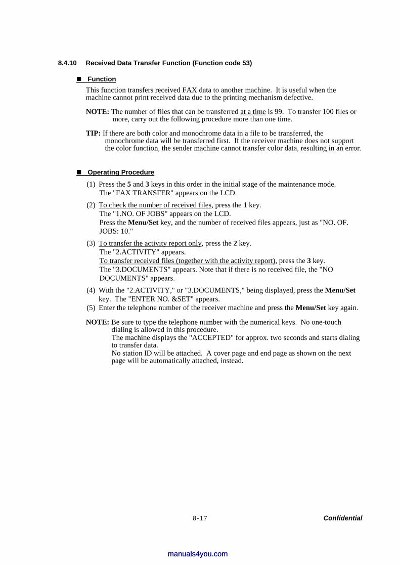
8-17 Confidential
8.4.10 Received Data Transfer Function (Function code 53)
Function This function transfers received FAX data to another machine. It is useful when the machine cannot print received data due to the printing mechanism defective.
NOTE: The number of files that can be transferred at a time is 99. To transfer 100 files or more, carry out the following procedure more than one time.
TIP: If there are both color and monochrome data in a file to be transferred, the monochrome data will be transferred first. If the receiver machine does not support the color function, the sender machine cannot transfer color data, resulting in an error.
Operating Procedure
(1) Press the 5 and 3 keys in this order in the initial stage of the maintenance mode. The "FAX TRANSFER" appears on the LCD.
(2) To check the number of received files, press the 1 key. The "1.NO. OF JOBS" appears on the LCD. Press the Menu/Set key, and the number of received files appears, just as "NO. OF. JOBS: 10."
(3) To transfer the activity report only, press the 2 key. The "2.ACTIVITY" appears. To transfer received files (together with the activity report), press the 3 key. The "3.DOCUMENTS" appears. Note that if there is no received file, the "NO DOCUMENTS" appears.
(4) With the "2.ACTIVITY," or "3.DOCUMENTS," being displayed, press the Menu/Set key. The "ENTER NO. &SET" appears.
(5) Enter the telephone number of the receiver machine and press the Menu/Set key again.
NOTE: Be sure to type the telephone number with the numerical keys. No one-touch dialing is allowed in this procedure. The machine displays the "ACCEPTED" for approx. two seconds and starts dialing to transfer data. No station ID will be attached. A cover page and end page as shown on the next page will be automatically attached, instead.
manuals4you.commanuals4you.com
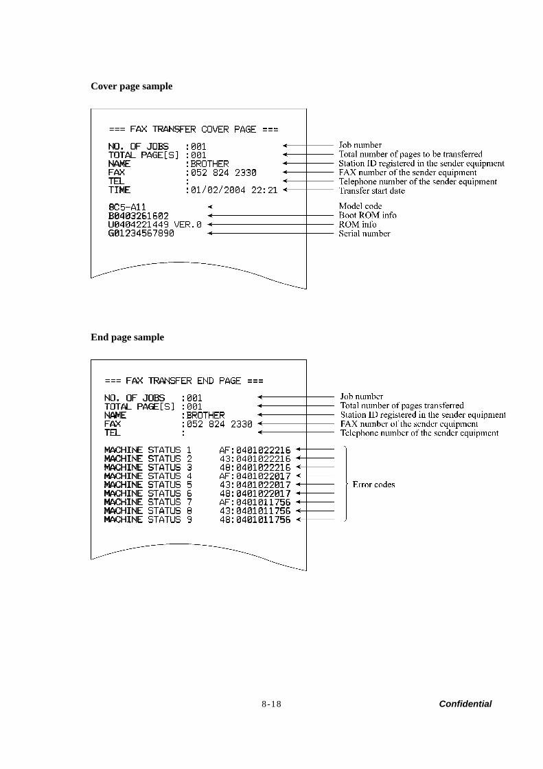
8-18 Confidential
Cover page sample
End page sample
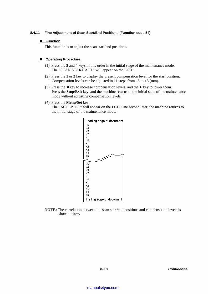
8-19 Confidential
8.4.11 Fine Adjustment of Scan Start/End Positions (Function code 54)
Function This function is to adjust the scan start/end positions.
Operating Procedure
(1) Press the 5 and 4 keys in this order in the initial stage of the maintenance mode. The “SCAN START ADJ.” will appear on the LCD.
(2) Press the 1 or 2 key to display the present compensation level for the start position. Compensation levels can be adjusted in 11 steps from –5 to +5 (mm).
(3) Press the key to increase compensation levels, and the key to lower them. Press the Stop/Exit key, and the machine returns to the initial state of the maintenance mode without adjusting compensation levels.
(4) Press the Menu/Set key. The “ACCEPTED” will appear on the LCD. One second later, the machine returns to the initial stage of the maintenance mode.
NOTE: The correlation between the scan start/end positions and compensation levels is shown below.
manuals4you.commanuals4you.com
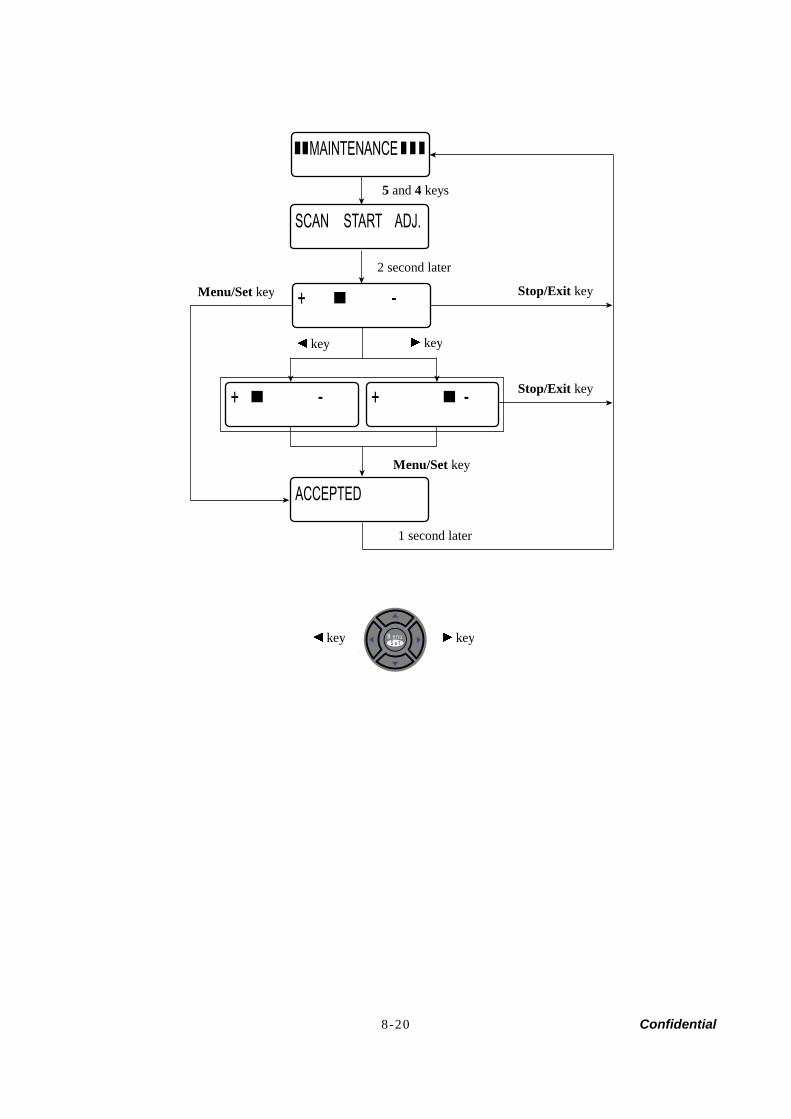
8-20 Confidential
MAINTENANCE
ACCEPTED
SCAN START ADJ.
+ -
+ - + -
5 and 4 keys
2 second later
Menu/Set key Stop/Exit key
Stop/Exit key
key key
1 second later
key key
Menu/Set key
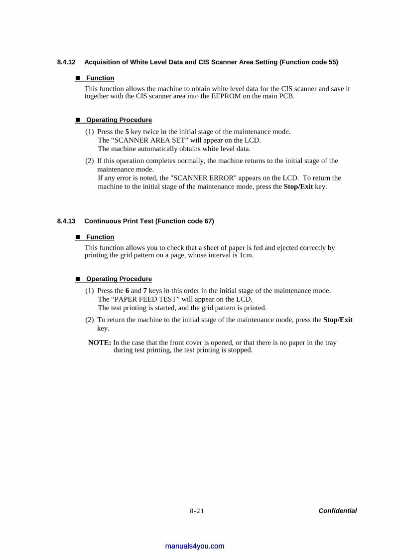
8-21 Confidential
8.4.12 Acquisition of White Level Data and CIS Scanner Area Setting (Function code 55)
Function This function allows the machine to obtain white level data for the CIS scanner and save it together with the CIS scanner area into the EEPROM on the main PCB.
Operating Procedure
(1) Press the 5 key twice in the initial stage of the maintenance mode. The “SCANNER AREA SET” will appear on the LCD. The machine automatically obtains white level data.
(2) If this operation completes normally, the machine returns to the initial stage of the maintenance mode. If any error is noted, the "SCANNER ERROR" appears on the LCD. To return the machine to the initial stage of the maintenance mode, press the Stop/Exit key.
8.4.13 Continuous Print Test (Function code 67)
Function This function allows you to check that a sheet of paper is fed and ejected correctly by printing the grid pattern on a page, whose interval is 1cm.
Operating Procedure
(1) Press the 6 and 7 keys in this order in the initial stage of the maintenance mode. The “PAPER FEED TEST” will appear on the LCD. The test printing is started, and the grid pattern is printed.
(2) To return the machine to the initial stage of the maintenance mode, press the Stop/Exit key.
NOTE: In the case that the front cover is opened, or that there is no paper in the tray during test printing, the test printing is stopped.
manuals4you.commanuals4you.com
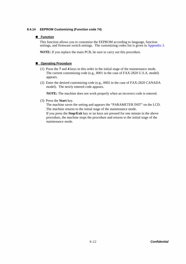
8-22 Confidential
8.4.14 EEPROM Customizing (Function code 74)
Function This function allows you to customize the EEPROM according to language, function settings, and firmware switch settings. The customizing codes list is given in Appendix 3.
NOTE: If you replace the main PCB, be sure to carry out this procedure.
Operating Procedure
(1) Press the 7 and 4 keys in this order in the initial stage of the maintenance mode. The current customizing code (e.g., 8001 in the case of FAX-2820 U.S.A. model) appears.
(2) Enter the desired customizing code (e.g., 0002 in the case of FAX-2820 CANADA model). The newly entered code appears.
NOTE: The machine does not work properly when an incorrect code is entered.
(3) Press the Start key. The machine saves the setting and appears the “PARAMETER INIT” on the LCD. The machine returns to the initial stage of the maintenance mode. If you press the Stop/Exit key or no keys are pressed for one minute in the above procedure, the machine stops the procedure and returns to the initial stage of the maintenance mode.
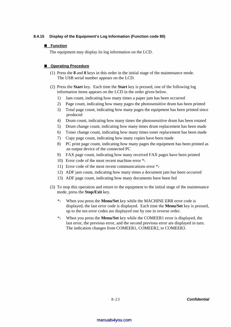
8-23 Confidential
8.4.15 Display of the Equipment’s Log Information (Function code 80)
Function The equipment may display its log information on the LCD.
Operating Procedure
(1) Press the 8 and 0 keys in this order in the initial stage of the maintenance mode. The USB serial number appears on the LCD.
(2) Press the Start key. Each time the Start key is pressed, one of the following log information items appears on the LCD in the order given below. 1) Jam count, indicating how many times a paper jam has been occurred 2) Page count, indicating how many pages the photosensitive drum has been printed 3) Total page count, indicating how many pages the equipment has been printed since
produced 4) Drum count, indicating how many times the photosensitive drum has been rotated 5) Drum change count, indicating how many times drum replacement has been made 6) Toner change count, indicating how many times toner replacement has been made 7) Copy page count, indicating how many copies have been made 8) PC print page count, indicating how many pages the equipment has been printed as
an output device of the connected PC 9) FAX page count, indicating how many received FAX pages have been printed 10) Error code of the most recent machine error *1 11) Error code of the most recent communications error *2 12) ADF jam count, indicating how many times a document jam has been occurred 13) ADF page count, indicating how many documents have been fed
(3) To stop this operation and return to the equipment to the initial stage of the maintenance mode, press the Stop/Exit key.
*1 When you press the Menu/Set key while the MACHINE ERR error code is displayed, the last error code is displayed. Each time the Menu/Set key is pressed, up to the ten error codes are displayed one by one in reverse order.
*2 When you press the Menu/Set key while the COMEER1 error is displayed, the last error, the previous error, and the second previous error are displayed in turn. The indication changes from COMEER1, COMEER2, to COMEER3.
manuals4you.commanuals4you.com
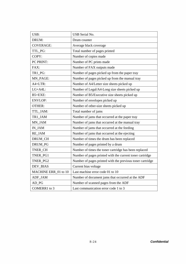
8-24 Confidential
USB: USB Serial No. DRUM: Drum counter COVERAGE: Average black coverage TTL_PG: Total number of pages printed COPY: Number of copies made PC PRINT: Number of PC prints made FAX: Number of FAX outputs made TR1_PG: Number of pages picked up from the paper tray MN_PAGE: Number of pages picked up from the manual tray A4+LTR: Number of A4/Letter size sheets picked up LG+A4L: Number of Legal/A4-Long size sheets picked up B5+EXE: Number of B5/Executive size sheets picked up ENVLOP: Number of envelopes picked up OTHER: Number of other-size sheets picked up TTL_JAM: Total number of jams TR1_JAM Number of jams that occurred at the paper tray MN_JAM Number of jams that occurred at the manual tray IN_JAM Number of jams that occurred at the feeding RE_JAM Number of jams that occurred at the ejecting DRUM_CH Number of times the drum has been replaced DRUM_PG Number of pages printed by a drum TNER_CH Number of times the toner cartridge has been replaced TNER_PG1 Number of pages printed with the current toner cartridge TNER_PG2 Number of pages printed with the previous toner cartridge DEV_BIAS Current bias voltage MACHINE ERR_01 to 10 Last machine error code 01 to 10 ADF_JAM Number of document jams that occurred at the ADF AD_PG Number of scanned pages from the ADF COMERR1 to 3 Last communication error code 1 to 3
8-25 Confidential
8.4.16 Machine Error Code Indication (Function code 82)
Function This function displays an error code of the last error on the LCD.
Operating Procedure
(1) Press the 8 and 2 keys in this order in the initial stage of the maintenance mode. The LCD shows the "MACHINE ERROR X X."
(2) Press the Stop/Exit key. Return to the initial stage of the maintenance mode.
8.4.17 Output of Transmission Log to the Telephone Line (Function code 87)
Function This function outputs the transmission log (that the machine has stored about the latest transmission) to the telephone line. It allows the service personnel to receive the transmission log of the user's machine at a remote location and use it for analyzing problems arising in the user's machine.
Operating Procedure
(1) If the user's machine has a transmission-related problem, call the user's machine at a remote location from your machine.
(2) If the line is connected, have the user perform the following: 1) Hook up the handset. 2) Press the Menu/Set, Start, Menu/Set, Start keys in this order. 3) Press the 8 and 7 keys.
The above operation makes the user's machine send CNG to your machine for sending the transmission log.
(3) If you hear the CNG sent from the user's machine, press the Start key of your machine. Your machine will start to receive the transmission log from the user's machine.
8.4.18 Cancellation of the Memory Security Mode
Function This procedure can cancel the memory security mode. Use this procedure if the user forgets his/her password entered when setting the memory security mode so as not to exit from the memory security mode.
NOTE: Carrying out this procedure will lose passwords previously entered but retain FAX messages received in the memory security mode.
Operating Procedure
(1) When the SECURE MODE is displayed on the LCD, press the Menu/Set key and # key together. Within two seconds, start to press the 2, 7, 9, 0 and 0 keys. The memory security mode will be canceled and the machine returns to the calendar clock screen.
manuals4you.commanuals4you.com

Confidential
CHAPTER 9ERROR INDICATION AND
TROUBLESHOOTING
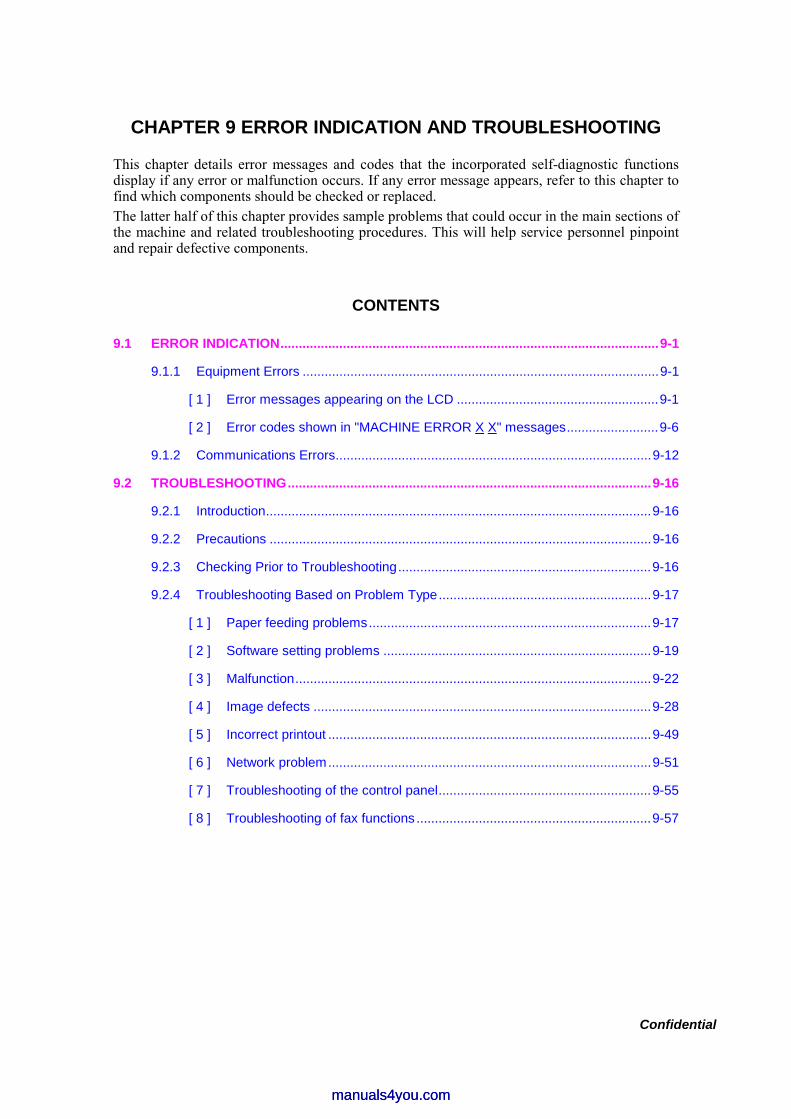
Confidential
CHAPTER 9 ERROR INDICATION AND TROUBLESHOOTING
This chapter details error messages and codes that the incorporated self-diagnostic functions display if any error or malfunction occurs. If any error message appears, refer to this chapter to find which components should be checked or replaced. The latter half of this chapter provides sample problems that could occur in the main sections of the machine and related troubleshooting procedures. This will help service personnel pinpoint and repair defective components.
CONTENTS
9.1 ERROR INDICATION.......................................................................................................9-1
9.1.1 Equipment Errors .................................................................................................9-1
[ 1 ] Error messages appearing on the LCD .......................................................9-1
[ 2 ] Error codes shown in "MACHINE ERROR X X" messages.........................9-6
9.1.2 Communications Errors......................................................................................9-12
9.2 TROUBLESHOOTING...................................................................................................9-16
9.2.1 Introduction.........................................................................................................9-16
9.2.2 Precautions ........................................................................................................9-16
9.2.3 Checking Prior to Troubleshooting.....................................................................9-16
9.2.4 Troubleshooting Based on Problem Type..........................................................9-17
[ 1 ] Paper feeding problems.............................................................................9-17
[ 2 ] Software setting problems .........................................................................9-19
[ 3 ] Malfunction.................................................................................................9-22
[ 4 ] Image defects ............................................................................................9-28
[ 5 ] Incorrect printout ........................................................................................9-49
[ 6 ] Network problem........................................................................................9-51
[ 7 ] Troubleshooting of the control panel..........................................................9-55
[ 8 ] Troubleshooting of fax functions ................................................................9-57
manuals4you.commanuals4you.com
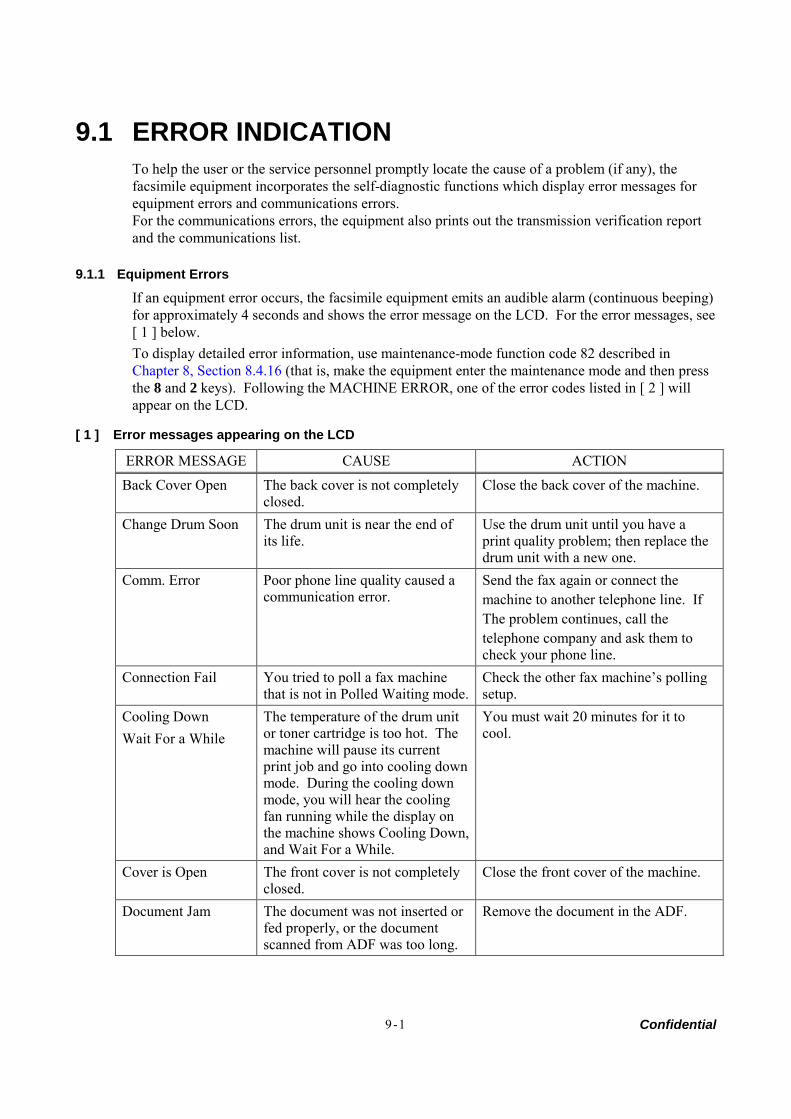
Confidential 9-1
9.1 ERROR INDICATION To help the user or the service personnel promptly locate the cause of a problem (if any), the facsimile equipment incorporates the self-diagnostic functions which display error messages for equipment errors and communications errors. For the communications errors, the equipment also prints out the transmission verification report and the communications list.
9.1.1 Equipment Errors
If an equipment error occurs, the facsimile equipment emits an audible alarm (continuous beeping) for approximately 4 seconds and shows the error message on the LCD. For the error messages, see [ 1 ] below. To display detailed error information, use maintenance-mode function code 82 described in Chapter 8, Section 8.4.16 (that is, make the equipment enter the maintenance mode and then press the 8 and 2 keys). Following the MACHINE ERROR, one of the error codes listed in [ 2 ] will appear on the LCD.
[ 1 ] Error messages appearing on the LCD
ERROR MESSAGE CAUSE ACTION
Back Cover Open The back cover is not completely closed.
Close the back cover of the machine.
Change Drum Soon The drum unit is near the end of its life.
Use the drum unit until you have a print quality problem; then replace the drum unit with a new one.
Comm. Error Poor phone line quality caused a communication error.
Send the fax again or connect the machine to another telephone line. If The problem continues, call the telephone company and ask them to check your phone line.
Connection Fail You tried to poll a fax machine that is not in Polled Waiting mode.
Check the other fax machine’s polling setup.
Cooling Down Wait For a While
The temperature of the drum unit or toner cartridge is too hot. The machine will pause its current print job and go into cooling down mode. During the cooling down mode, you will hear the cooling fan running while the display on the machine shows Cooling Down, and Wait For a While.
You must wait 20 minutes for it to cool.
Cover is Open The front cover is not completely closed.
Close the front cover of the machine.
Document Jam The document was not inserted or fed properly, or the document scanned from ADF was too long.
Remove the document in the ADF.
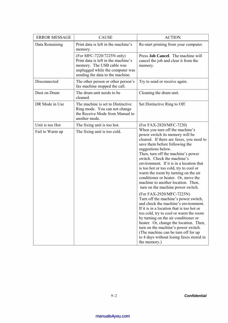
Confidential 9-2
ERROR MESSAGE CAUSE ACTION
Print data is left in the machine’s memory.
Re-start printing from your computer. Data Remaining
(For MFC-7220/7225N only) Print data is left in the machine’s memory. The USB cable was unplugged while the computer was sending the data to the machine.
Press Job Cancel. The machine will cancel the job and clear it from the memory.
Disconnected The other person or other person’s fax machine stopped the call.
Try to send or receive again.
Dust on Drum The drum unit needs to be cleaned.
Cleaning the drum unit.
DR Mode in Use The machine is set to Distinctive Ring mode. You can not change the Receive Mode from Manual to another mode.
Set Distinctive Ring to Off.
Unit is too Hot The fixing unit is too hot. Fail to Warm up The fixing unit is too cold.
(For FAX-2820/MFC-7220) When you turn off the machine’s power switch its memory will be cleared. If there are faxes, you need to save them before following the suggestions below. Then, turn off the machine’s power switch. Check the machine’s environment. If it is in a location that is too hot or too cold, try to cool or warm the room by turning on the air conditioner or heater. Or, move the machine to another location. Then, turn on the machine power switch. (For FAX-2920/MFC-7225N) Turn off the machine’s power switch, and check the machine’s environment. If it is in a location that is too hot or too cold, try to cool or warm the room by turning on the air conditioner or heater. Or, change the location. Then, turn on the machine’s power switch. (The machine can be turn off for up to 4 days without losing faxes stored inthe memory.)
manuals4you.commanuals4you.com
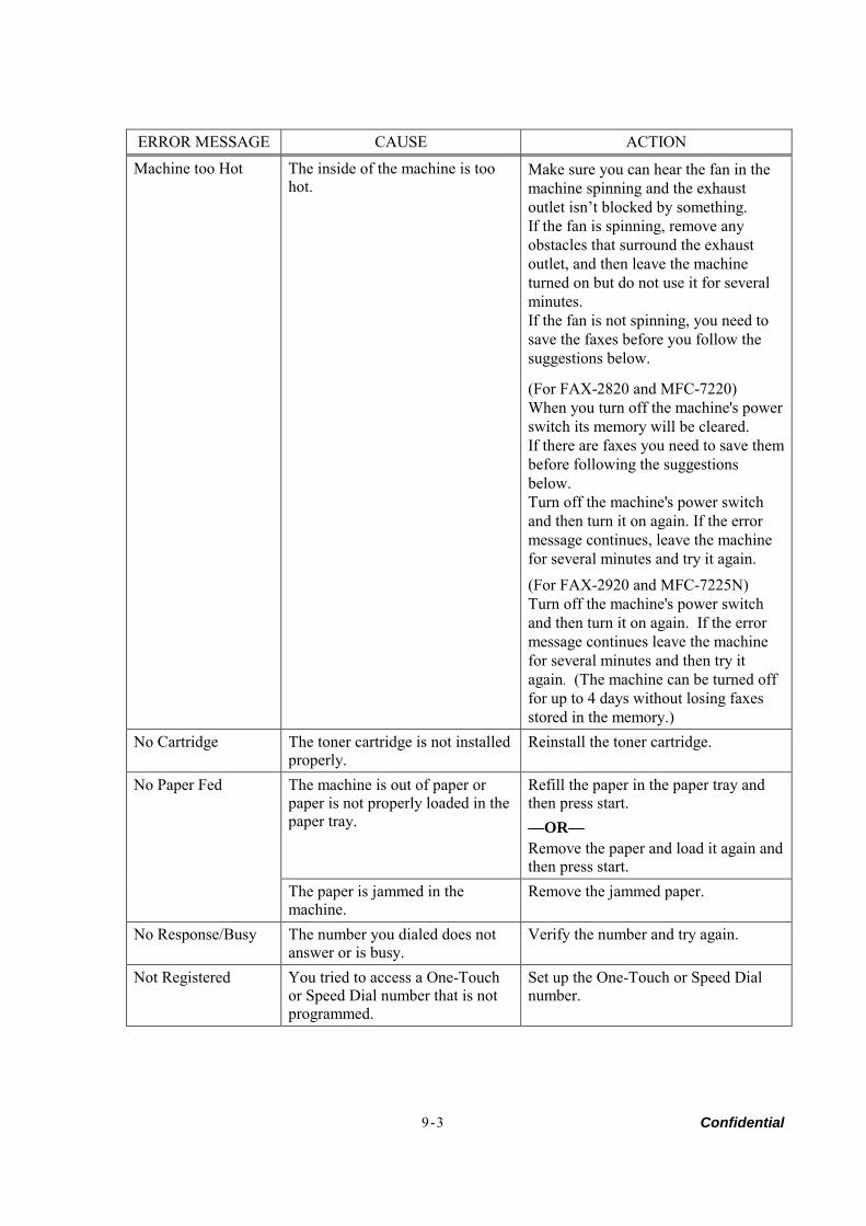
Confidential 9-3
ERROR MESSAGE CAUSE ACTION
Machine too Hot The inside of the machine is too hot.
Make sure you can hear the fan in the machine spinning and the exhaust outlet isn’t blocked by something. If the fan is spinning, remove any obstacles that surround the exhaust outlet, and then leave the machine turned on but do not use it for several minutes. If the fan is not spinning, you need to save the faxes before you follow the suggestions below.
(For FAX-2820 and MFC-7220) When you turn off the machine's powerswitch its memory will be cleared. If there are faxes you need to save them before following the suggestions below. Turn off the machine's power switch and then turn it on again. If the error message continues, leave the machine for several minutes and try it again. (For FAX-2920 and MFC-7225N) Turn off the machine's power switch and then turn it on again. If the error message continues leave the machine for several minutes and then try it again. (The machine can be turned off for up to 4 days without losing faxes stored in the memory.)
No Cartridge The toner cartridge is not installed properly.
Reinstall the toner cartridge.
The machine is out of paper or paper is not properly loaded in the paper tray.
Refill the paper in the paper tray and then press start. —OR— Remove the paper and load it again and then press start.
No Paper Fed
The paper is jammed in the machine.
Remove the jammed paper.
No Response/Busy The number you dialed does not answer or is busy.
Verify the number and try again.
Not Registered You tried to access a One-Touch or Speed Dial number that is not programmed.
Set up the One-Touch or Speed Dial number.
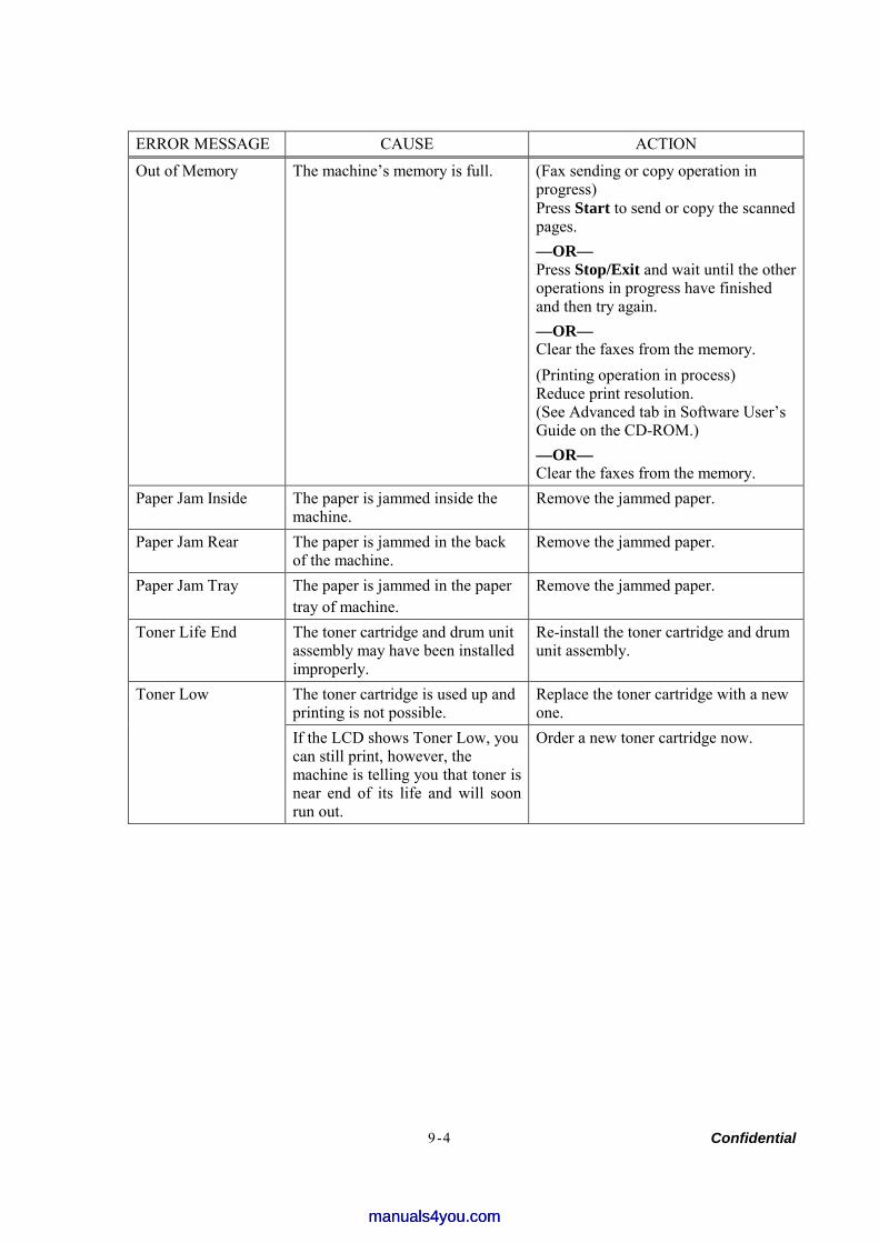
Confidential 9-4
ERROR MESSAGE CAUSE ACTION
Out of Memory The machine’s memory is full. (Fax sending or copy operation in progress) Press Start to send or copy the scanned pages. —OR— Press Stop/Exit and wait until the other operations in progress have finished and then try again. —OR— Clear the faxes from the memory. (Printing operation in process) Reduce print resolution. (See Advanced tab in Software User’s Guide on the CD-ROM.) —OR— Clear the faxes from the memory.
Paper Jam Inside The paper is jammed inside the machine.
Remove the jammed paper.
Paper Jam Rear The paper is jammed in the back of the machine.
Remove the jammed paper.
Paper Jam Tray The paper is jammed in the paper tray of machine.
Remove the jammed paper.
Toner Life End The toner cartridge and drum unit assembly may have been installed improperly.
Re-install the toner cartridge and drum unit assembly.
The toner cartridge is used up and printing is not possible.
Replace the toner cartridge with a new one.
Toner Low
If the LCD shows Toner Low, you can still print, however, the machine is telling you that toner is near end of its life and will soon run out.
Order a new toner cartridge now.
manuals4you.commanuals4you.com
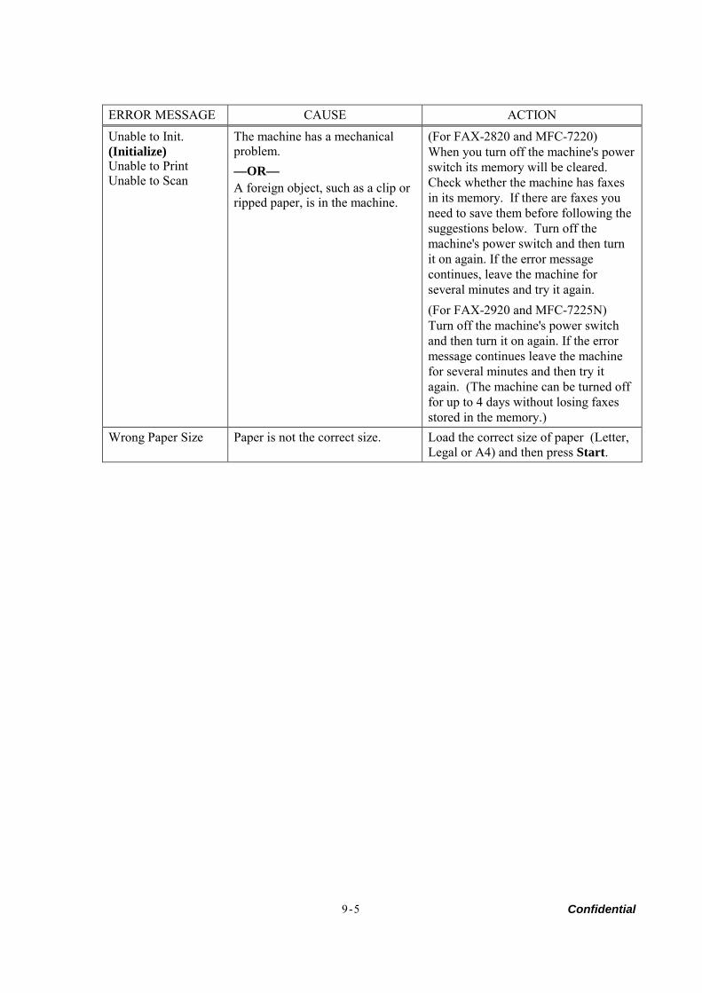
Confidential 9-5
ERROR MESSAGE CAUSE ACTION
Unable to Init. (Initialize) Unable to Print Unable to Scan
The machine has a mechanical problem. —OR— A foreign object, such as a clip or ripped paper, is in the machine.
(For FAX-2820 and MFC-7220) When you turn off the machine's powerswitch its memory will be cleared. Check whether the machine has faxes in its memory. If there are faxes you need to save them before following the suggestions below. Turn off the machine's power switch and then turn it on again. If the error message continues, leave the machine for several minutes and try it again. (For FAX-2920 and MFC-7225N) Turn off the machine's power switch and then turn it on again. If the error message continues leave the machine for several minutes and then try it again. (The machine can be turned off for up to 4 days without losing faxes stored in the memory.)
Wrong Paper Size Paper is not the correct size. Load the correct size of paper (Letter, Legal or A4) and then press Start.
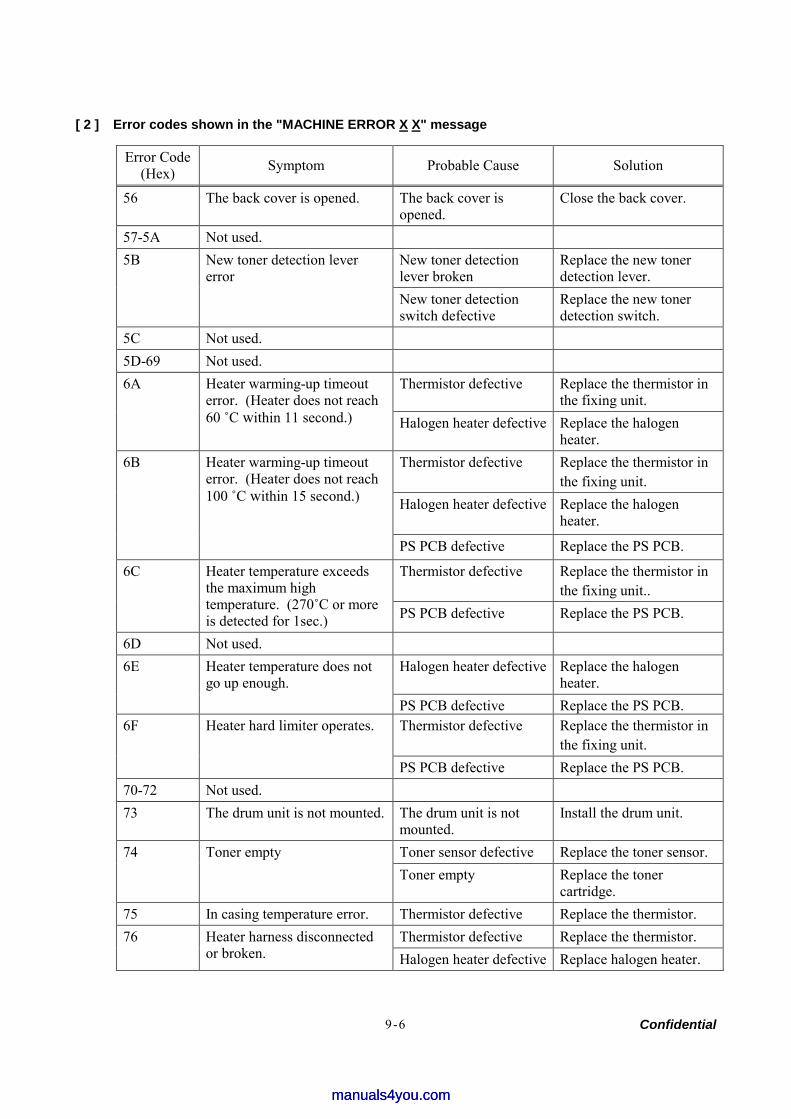
Confidential 9-6
[ 2 ] Error codes shown in the "MACHINE ERROR X X" message
Error Code (Hex) Symptom Probable Cause Solution
56 The back cover is opened. The back cover is opened.
Close the back cover.
57-5A Not used. New toner detection lever broken
Replace the new toner detection lever.
5B New toner detection lever error
New toner detection switch defective
Replace the new toner detection switch.
5C Not used. 5D-69 Not used.
Thermistor defective Replace the thermistor in the fixing unit.
6A Heater warming-up timeout error. (Heater does not reach 60 ˚С within 11 second.) Halogen heater defective Replace the halogen
heater. Thermistor defective Replace the thermistor in
the fixing unit. Halogen heater defective
Replace the halogen heater.
6B Heater warming-up timeout error. (Heater does not reach 100 ˚С within 15 second.)
PS PCB defective Replace the PS PCB.
Thermistor defective Replace the thermistor in the fixing unit..
6C Heater temperature exceeds the maximum high temperature. (270˚С or more is detected for 1sec.) PS PCB defective Replace the PS PCB.
6D Not used. Halogen heater defective Replace the halogen
heater. 6E Heater temperature does not
go up enough. PS PCB defective Replace the PS PCB. Thermistor defective Replace the thermistor in
the fixing unit. 6F Heater hard limiter operates.
PS PCB defective Replace the PS PCB. 70-72 Not used. 73 The drum unit is not mounted. The drum unit is not
mounted. Install the drum unit.
Toner sensor defective Replace the toner sensor. 74 Toner empty Toner empty Replace the toner
cartridge. 75 In casing temperature error. Thermistor defective Replace the thermistor.
Thermistor defective Replace the thermistor. 76 Heater harness disconnected or broken. Halogen heater defective Replace halogen heater.
manuals4you.commanuals4you.com
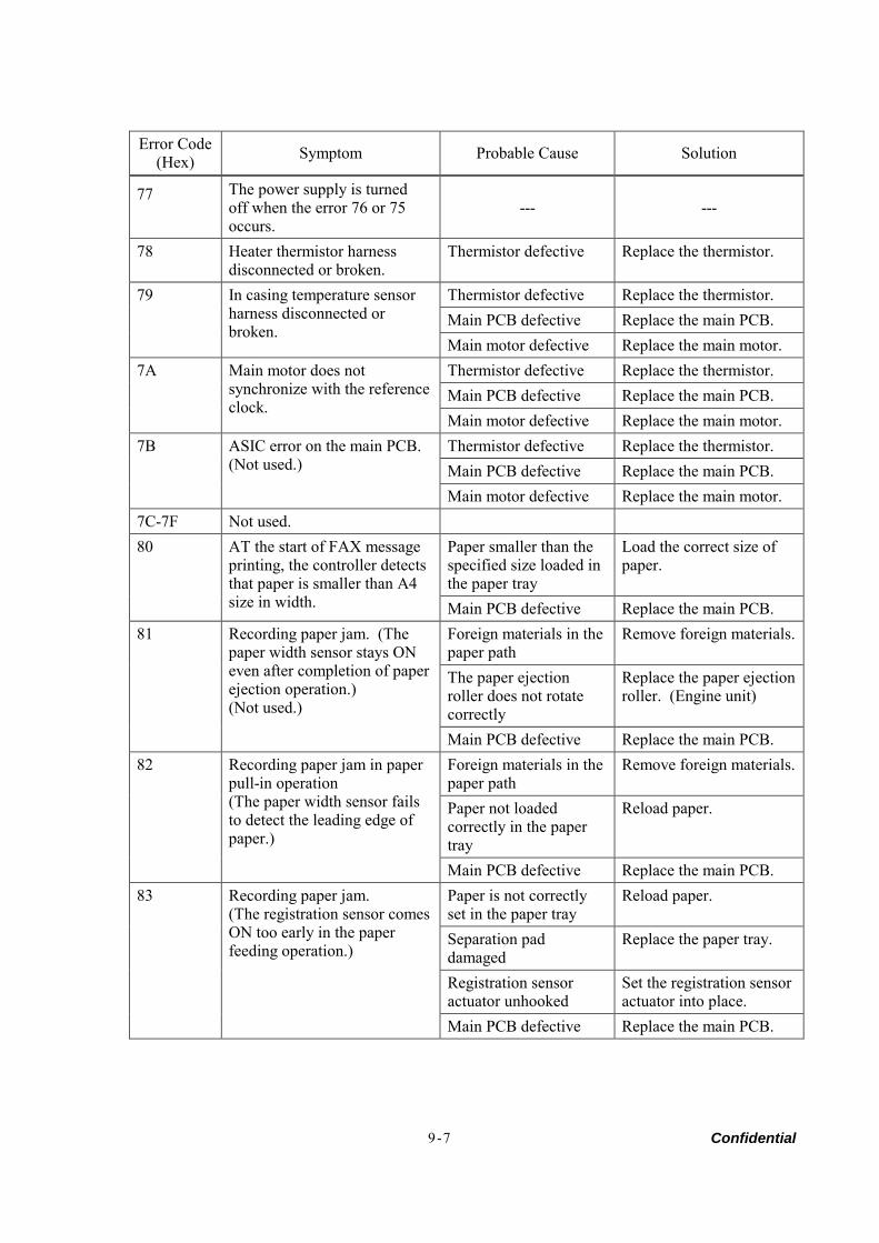
Confidential 9-7
Error Code (Hex) Symptom Probable Cause Solution
77
The power supply is turned off when the error 76 or 75 occurs.
--- ---
78 Heater thermistor harness disconnected or broken.
Thermistor defective Replace the thermistor.
Thermistor defective Replace the thermistor. Main PCB defective Replace the main PCB.
79 In casing temperature sensor harness disconnected or broken.
Main motor defective Replace the main motor. Thermistor defective Replace the thermistor. Main PCB defective Replace the main PCB.
7A Main motor does not synchronize with the reference clock.
Main motor defective Replace the main motor. Thermistor defective Replace the thermistor. Main PCB defective Replace the main PCB.
7B ASIC error on the main PCB. (Not used.)
Main motor defective Replace the main motor. 7C-7F Not used.
Paper smaller than the specified size loaded in the paper tray
Load the correct size of paper.
80 AT the start of FAX message printing, the controller detects that paper is smaller than A4 size in width. Main PCB defective Replace the main PCB.
Foreign materials in the paper path
Remove foreign materials.
The paper ejection roller does not rotate correctly
Replace the paper ejection roller. (Engine unit)
81 Recording paper jam. (The paper width sensor stays ON even after completion of paper ejection operation.) (Not used.)
Main PCB defective Replace the main PCB. Foreign materials in the paper path
Remove foreign materials.
Paper not loaded correctly in the paper tray
Reload paper.
82 Recording paper jam in paper pull-in operation (The paper width sensor fails to detect the leading edge of paper.)
Main PCB defective Replace the main PCB. Paper is not correctly set in the paper tray
Reload paper.
Separation pad damaged
Replace the paper tray.
Registration sensor actuator unhooked
Set the registration sensor actuator into place.
83 Recording paper jam. (The registration sensor comes ON too early in the paper feeding operation.)
Main PCB defective Replace the main PCB.
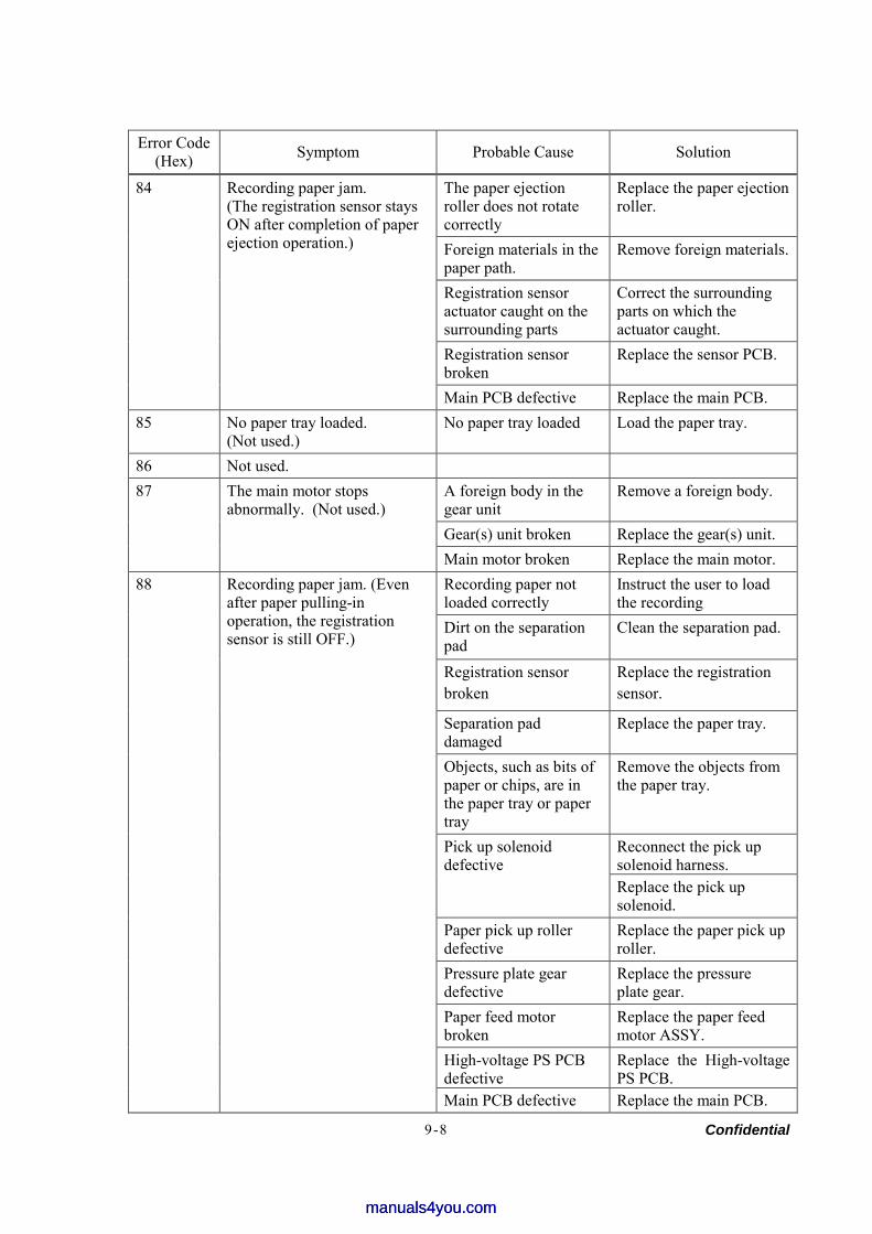
Confidential 9-8
Error Code (Hex) Symptom Probable Cause Solution
The paper ejection roller does not rotate correctly
Replace the paper ejection roller.
Foreign materials in the paper path.
Remove foreign materials.
Registration sensor actuator caught on the surrounding parts
Correct the surrounding parts on which the actuator caught.
Registration sensor broken
Replace the sensor PCB.
84 Recording paper jam. (The registration sensor stays ON after completion of paper ejection operation.)
Main PCB defective Replace the main PCB. 85 No paper tray loaded.
(Not used.) No paper tray loaded Load the paper tray.
86 Not used. A foreign body in the gear unit
Remove a foreign body.
Gear(s) unit broken Replace the gear(s) unit.
87 The main motor stops abnormally. (Not used.)
Main motor broken Replace the main motor. Recording paper not loaded correctly
Instruct the user to load the recording
Dirt on the separation pad
Clean the separation pad.
Registration sensor broken
Replace the registration sensor.
Separation pad damaged
Replace the paper tray.
Objects, such as bits of paper or chips, are in the paper tray or paper tray
Remove the objects from the paper tray.
Reconnect the pick up solenoid harness.
Pick up solenoid defective
Replace the pick up solenoid.
Paper pick up roller defective
Replace the paper pick up roller.
Pressure plate gear defective
Replace the pressure plate gear.
Paper feed motor broken
Replace the paper feed motor ASSY.
High-voltage PS PCB defective
Replace the High-voltage PS PCB.
88 Recording paper jam. (Even after paper pulling-in operation, the registration sensor is still OFF.)
Main PCB defective Replace the main PCB.
manuals4you.commanuals4you.com
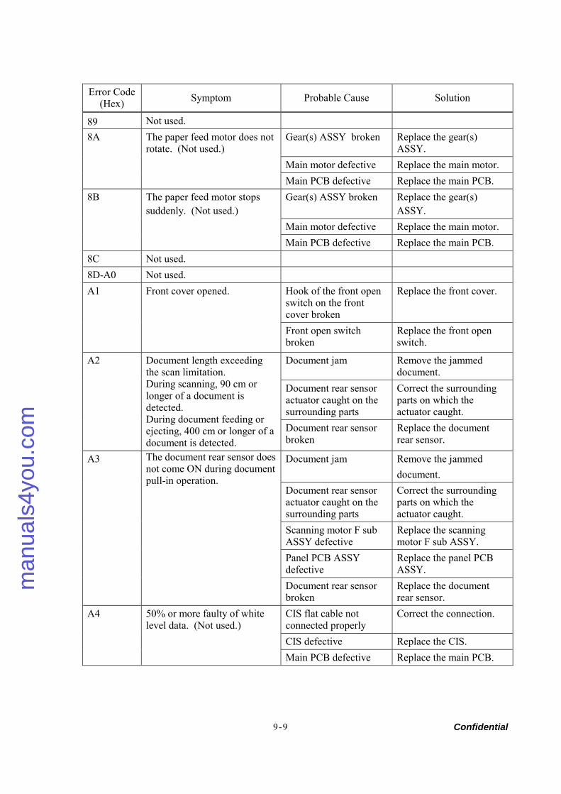
Confidential 9-9
Error Code (Hex) Symptom Probable Cause Solution
89 Not used. Gear(s) ASSY broken Replace the gear(s)
ASSY. Main motor defective Replace the main motor.
8A The paper feed motor does not rotate. (Not used.)
Main PCB defective Replace the main PCB. Gear(s) ASSY broken Replace the gear(s)
ASSY. Main motor defective Replace the main motor.
8B The paper feed motor stops suddenly. (Not used.)
Main PCB defective Replace the main PCB. 8C Not used. 8D-A0 Not used.
Hook of the front open switch on the front cover broken
Replace the front cover. A1 Front cover opened.
Front open switch broken
Replace the front open switch.
Document jam Remove the jammed document.
Document rear sensor actuator caught on the surrounding parts
Correct the surrounding parts on which the actuator caught.
A2 Document length exceeding the scan limitation. During scanning, 90 cm or longer of a document is detected. During document feeding or ejecting, 400 cm or longer of a document is detected.
Document rear sensor broken
Replace the document rear sensor.
Document jam Remove the jammed document.
Document rear sensor actuator caught on the surrounding parts
Correct the surrounding parts on which the actuator caught.
Scanning motor F sub ASSY defective
Replace the scanning motor F sub ASSY.
Panel PCB ASSY defective
Replace the panel PCB ASSY.
A3 The document rear sensor does not come ON during document pull-in operation.
Document rear sensor broken
Replace the document rear sensor.
CIS flat cable not connected properly
Correct the connection.
CIS defective Replace the CIS.
A4 50% or more faulty of white level data. (Not used.)
Main PCB defective Replace the main PCB.
man
uals
4you
.com
man
uals
4you
.com
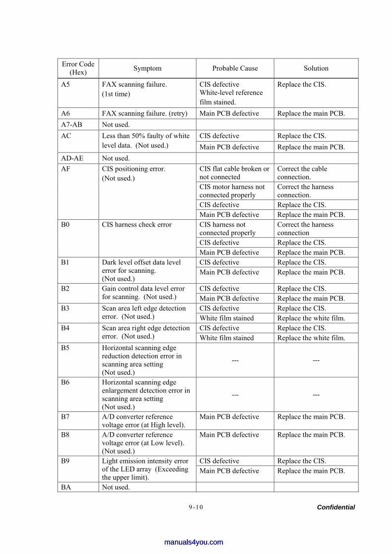
Confidential 9-10
Error Code (Hex) Symptom Probable Cause Solution
A5 FAX scanning failure. (1st time)
CIS defective White-level reference film stained.
Replace the CIS.
A6 FAX scanning failure. (retry) Main PCB defective Replace the main PCB. A7-AB Not used.
CIS defective Replace the CIS. AC Less than 50% faulty of white level data. (Not used.) Main PCB defective Replace the main PCB.
AD-AE Not used. CIS flat cable broken or not connected
Correct the cable connection.
CIS motor harness not connected properly
Correct the harness connection.
CIS defective Replace the CIS.
AF CIS positioning error. (Not used.)
Main PCB defective Replace the main PCB. CIS harness not connected properly
Correct the harness connection
CIS defective Replace the CIS.
B0 CIS harness check error
Main PCB defective Replace the main PCB. CIS defective Replace the CIS. B1 Dark level offset data level
error for scanning. (Not used.)
Main PCB defective Replace the main PCB.
CIS defective Replace the CIS. B2 Gain control data level error for scanning. (Not used.) Main PCB defective Replace the main PCB.
CIS defective Replace the CIS. B3 Scan area left edge detection error. (Not used.) White film stained Replace the white film.
CIS defective Replace the CIS. B4 Scan area right edge detection error. (Not used.) White film stained Replace the white film.
B5 Horizontal scanning edge reduction detection error in scanning area setting (Not used.)
--- ---
B6 Horizontal scanning edge enlargement detection error in scanning area setting (Not used.)
--- ---
B7 A/D converter reference voltage error (at High level).
Main PCB defective Replace the main PCB.
B8 A/D converter reference voltage error (at Low level). (Not used.)
Main PCB defective Replace the main PCB.
CIS defective Replace the CIS. B9 Light emission intensity error of the LED array (Exceeding the upper limit).
Main PCB defective Replace the main PCB.
BA Not used.
manuals4you.commanuals4you.com
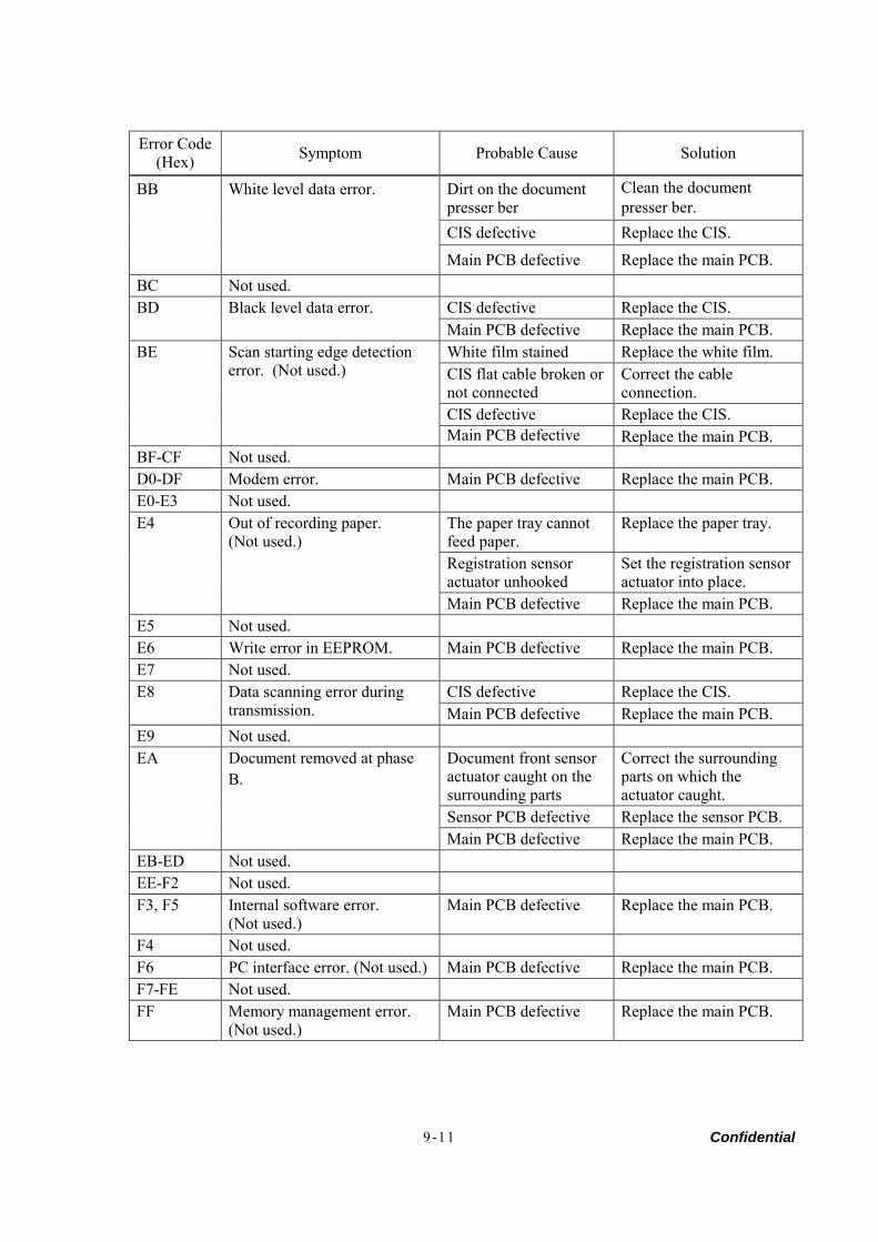
Confidential 9-11
Error Code (Hex) Symptom Probable Cause Solution
Dirt on the document presser ber
Clean the document presser ber.
CIS defective Replace the CIS.
BB
White level data error.
Main PCB defective Replace the main PCB.
BC Not used. CIS defective Replace the CIS. BD Black level data error. Main PCB defective Replace the main PCB. White film stained Replace the white film. CIS flat cable broken or not connected
Correct the cable connection.
CIS defective Replace the CIS.
BE Scan starting edge detection error. (Not used.)
Main PCB defective Replace the main PCB. BF-CF Not used. D0-DF Modem error. Main PCB defective Replace the main PCB. E0-E3 Not used.
The paper tray cannot feed paper.
Replace the paper tray.
Registration sensor actuator unhooked
Set the registration sensoractuator into place.
E4 Out of recording paper. (Not used.)
Main PCB defective Replace the main PCB. E5 Not used. E6 Write error in EEPROM. Main PCB defective Replace the main PCB. E7 Not used.
CIS defective Replace the CIS. E8 Data scanning error during transmission. Main PCB defective Replace the main PCB.
E9 Not used. Document front sensor actuator caught on the surrounding parts
Correct the surrounding parts on which the actuator caught.
Sensor PCB defective Replace the sensor PCB.
EA Document removed at phase B.
Main PCB defective Replace the main PCB. EB-ED Not used. EE-F2 Not used. F3, F5 Internal software error.
(Not used.) Main PCB defective Replace the main PCB.
F4 Not used. F6 PC interface error. (Not used.) Main PCB defective Replace the main PCB. F7-FE Not used. FF Memory management error.
(Not used.) Main PCB defective Replace the main PCB.
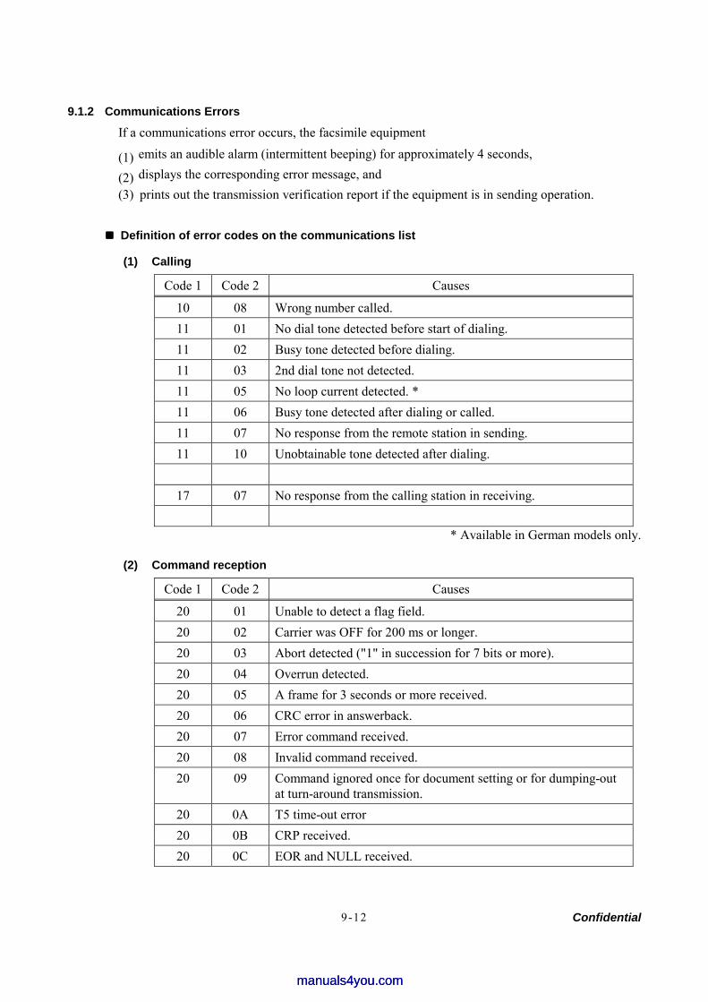
Confidential 9-12
9.1.2 Communications Errors
If a communications error occurs, the facsimile equipment
(1) emits an audible alarm (intermittent beeping) for approximately 4 seconds,
(2) displays the corresponding error message, and (3) prints out the transmission verification report if the equipment is in sending operation.
Definition of error codes on the communications list
(1) Calling
Code 1 Code 2 Causes
10 08 Wrong number called. 11 01 No dial tone detected before start of dialing. 11 02 Busy tone detected before dialing. 11 03 2nd dial tone not detected. 11 05 No loop current detected. * 11 06 Busy tone detected after dialing or called. 11 07 No response from the remote station in sending. 11 10 Unobtainable tone detected after dialing.
17 07 No response from the calling station in receiving.
* Available in German models only.
(2) Command reception
Code 1 Code 2 Causes
20 01 Unable to detect a flag field. 20 02 Carrier was OFF for 200 ms or longer. 20 03 Abort detected ("1" in succession for 7 bits or more). 20 04 Overrun detected. 20 05 A frame for 3 seconds or more received. 20 06 CRC error in answerback. 20 07 Error command received. 20 08 Invalid command received. 20 09 Command ignored once for document setting or for dumping-out
at turn-around transmission. 20 0A T5 time-out error 20 0B CRP received. 20 0C EOR and NULL received.
manuals4you.commanuals4you.com
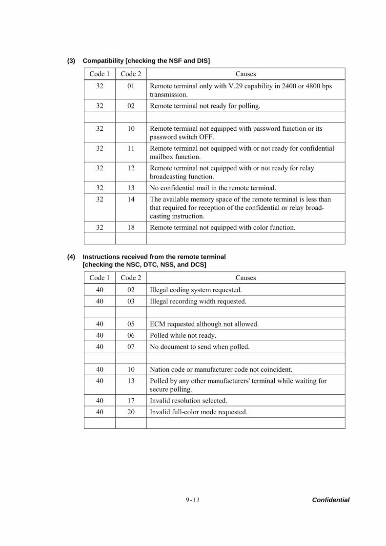
Confidential 9-13
(3) Compatibility [checking the NSF and DIS]
Code 1 Code 2 Causes
32 01 Remote terminal only with V.29 capability in 2400 or 4800 bps transmission.
32 02 Remote terminal not ready for polling.
32 10 Remote terminal not equipped with password function or its password switch OFF.
32 11 Remote terminal not equipped with or not ready for confidential mailbox function.
32 12 Remote terminal not equipped with or not ready for relay broadcasting function.
32 13 No confidential mail in the remote terminal. 32 14 The available memory space of the remote terminal is less than
that required for reception of the confidential or relay broad- casting instruction.
32 18 Remote terminal not equipped with color function.
(4) Instructions received from the remote terminal
[checking the NSC, DTC, NSS, and DCS]
Code 1 Code 2 Causes
40 02 Illegal coding system requested. 40 03 Illegal recording width requested.
40 05 ECM requested although not allowed. 40 06 Polled while not ready. 40 07 No document to send when polled.
40 10 Nation code or manufacturer code not coincident. 40 13 Polled by any other manufacturers' terminal while waiting for
secure polling. 40 17 Invalid resolution selected. 40 20 Invalid full-color mode requested.
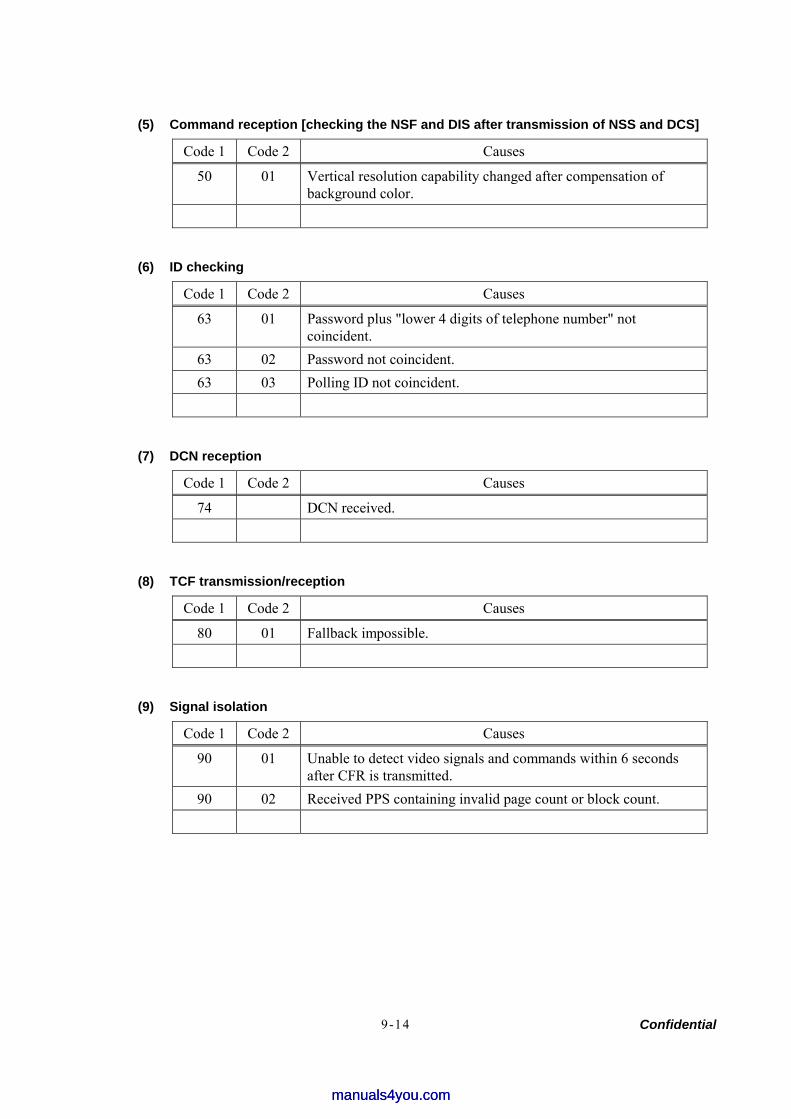
Confidential 9-14
(5) Command reception [checking the NSF and DIS after transmission of NSS and DCS]
Code 1 Code 2 Causes
50 01 Vertical resolution capability changed after compensation of background color.
(6) ID checking
Code 1 Code 2 Causes
63 01 Password plus "lower 4 digits of telephone number" not coincident.
63 02 Password not coincident. 63 03 Polling ID not coincident.
(7) DCN reception
Code 1 Code 2 Causes
74 DCN received.
(8) TCF transmission/reception
Code 1 Code 2 Causes
80 01 Fallback impossible.
(9) Signal isolation
Code 1 Code 2 Causes
90 01 Unable to detect video signals and commands within 6 seconds after CFR is transmitted.
90 02 Received PPS containing invalid page count or block count.
manuals4you.commanuals4you.com
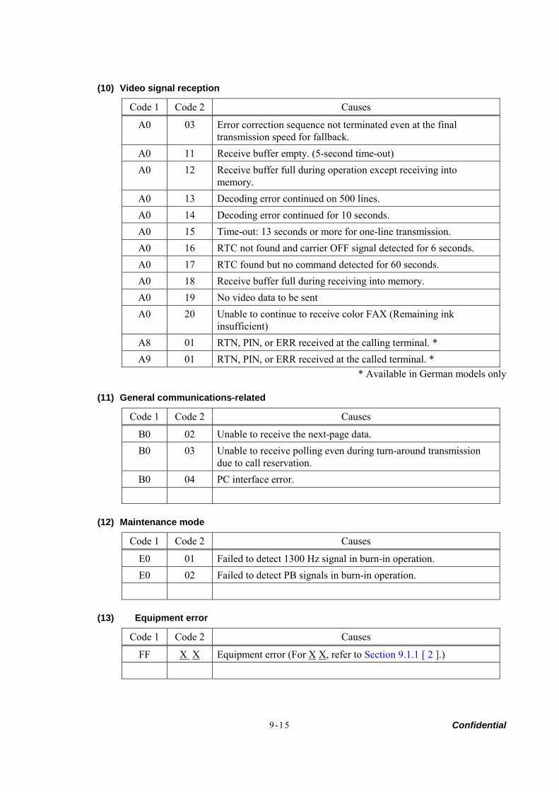
Confidential 9-15
(10) Video signal reception
Code 1 Code 2 Causes
A0 03 Error correction sequence not terminated even at the final transmission speed for fallback.
A0 11 Receive buffer empty. (5-second time-out) A0 12 Receive buffer full during operation except receiving into
memory. A0 13 Decoding error continued on 500 lines. A0 14 Decoding error continued for 10 seconds. A0 15 Time-out: 13 seconds or more for one-line transmission. A0 16 RTC not found and carrier OFF signal detected for 6 seconds. A0 17 RTC found but no command detected for 60 seconds. A0 18 Receive buffer full during receiving into memory. A0 19 No video data to be sent A0 20 Unable to continue to receive color FAX (Remaining ink
insufficient) A8 01 RTN, PIN, or ERR received at the calling terminal. * A9 01 RTN, PIN, or ERR received at the called terminal. *
* Available in German models only
(11) General communications-related
Code 1 Code 2 Causes
B0 02 Unable to receive the next-page data. B0 03 Unable to receive polling even during turn-around transmission
due to call reservation. B0 04 PC interface error.
(12) Maintenance mode
Code 1 Code 2 Causes
E0 01 Failed to detect 1300 Hz signal in burn-in operation. E0 02 Failed to detect PB signals in burn-in operation.
(13) Equipment error
Code 1 Code 2 Causes
FF X X Equipment error (For X X, refer to Section 9.1.1 [ 2 ].)
Confidential 9-16
9.2 TROUBLESHOOTING 9.2.1 Introduction
This section gives the service personnel some of the troubleshooting procedures to be followed if an error or malfunction occurs with the facsimile equipment. It is impossible to anticipate all of the possible problems which may occur in future and determine the troubleshooting procedures, so this section covers some sample problems. However, those samples will help service personnel pinpoint and repair other defective elements if he/she analyzes and examines them well.
9.2.2 Precautions
Be sure to observe the following to prevent the secondary troubles from happening:
(1) Always unplug the AC power cord from the outlet when removing the covers and PCBs, adjusting the mechanisms, or conducting continuity testing with a circuit tester.
(2) When disconnecting the connectors, do not pull the lead wires but hold the connector housings.
(3) Before handling the PCBs, touch a metal portion of the machine to discharge static electricity charged in your body. When repairing the PCBs, handle them with extra care.
After repairing the defective section, be sure to check again if the repaired section works correctly. Also record the troubleshooting procedure so that it would be of use for future trouble occurrence.
9.2.3 Checking Prior to Troubleshooting
Prior to proceeding to the troubleshooting procedures given in Section 9.2.4, make the following initial checks: Environmental conditions Check that: (1) The machine is placed on a flat, firm surface. (2) The machine is used in a clean environment at or near normal room temperature (10°C to
35°C) with normal relative humidity (20 to 80%). (3) The machine is not exposed to direct sunlight or harmful gases. Power requirements Check that: (1) The power supply specified on the rating plate on the machine is used. The supply voltage
stays within the rating ±10%. (2) Each voltage level on AC input lines and DC lines are correct. (3) All cables and harnesses are firmly connected. (4) None of the fuses are blown. Recording paper Check that: (1) A recommended type of recording paper is used. (2) The recording paper is not dampened. Drum unit (1) The drum unit (including the toner cartridge) is installed correctly.
manuals4you.commanuals4you.com
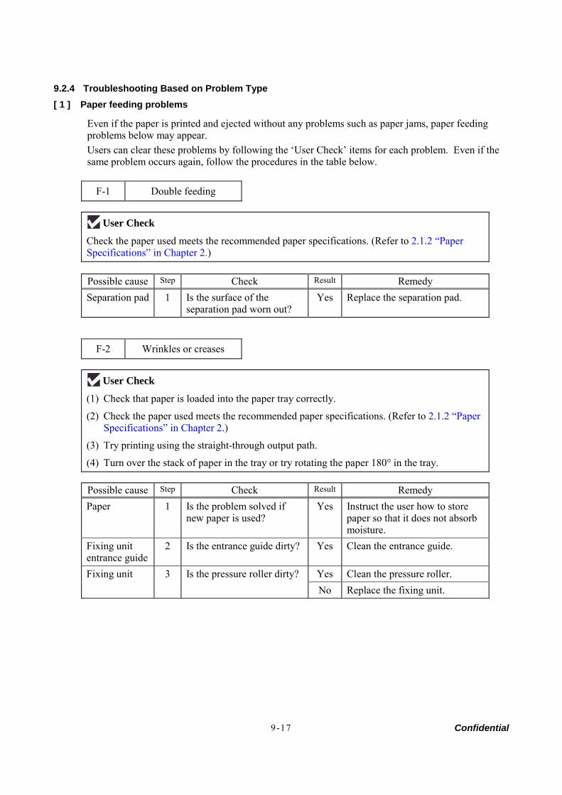
Confidential 9-17
9.2.4 Troubleshooting Based on Problem Type [ 1 ] Paper feeding problems
Even if the paper is printed and ejected without any problems such as paper jams, paper feeding problems below may appear. Users can clear these problems by following the ‘User Check’ items for each problem. Even if the same problem occurs again, follow the procedures in the table below.
F-1 Double feeding
User Check Check the paper used meets the recommended paper specifications. (Refer to 2.1.2 “Paper Specifications” in Chapter 2.)
Possible cause Step Check Result Remedy Separation pad 1 Is the surface of the
separation pad worn out? Yes Replace the separation pad.
F-2 Wrinkles or creases
User Check (1) Check that paper is loaded into the paper tray correctly.
(2) Check the paper used meets the recommended paper specifications. (Refer to 2.1.2 “Paper Specifications” in Chapter 2.)
(3) Try printing using the straight-through output path.
(4) Turn over the stack of paper in the tray or try rotating the paper 180° in the tray.
Possible cause Step Check Result Remedy Paper 1 Is the problem solved if
new paper is used? Yes Instruct the user how to store
paper so that it does not absorb moisture.
Fixing unit entrance guide
2 Is the entrance guide dirty? Yes Clean the entrance guide.
Yes Clean the pressure roller. Fixing unit 3 Is the pressure roller dirty? No Replace the fixing unit.
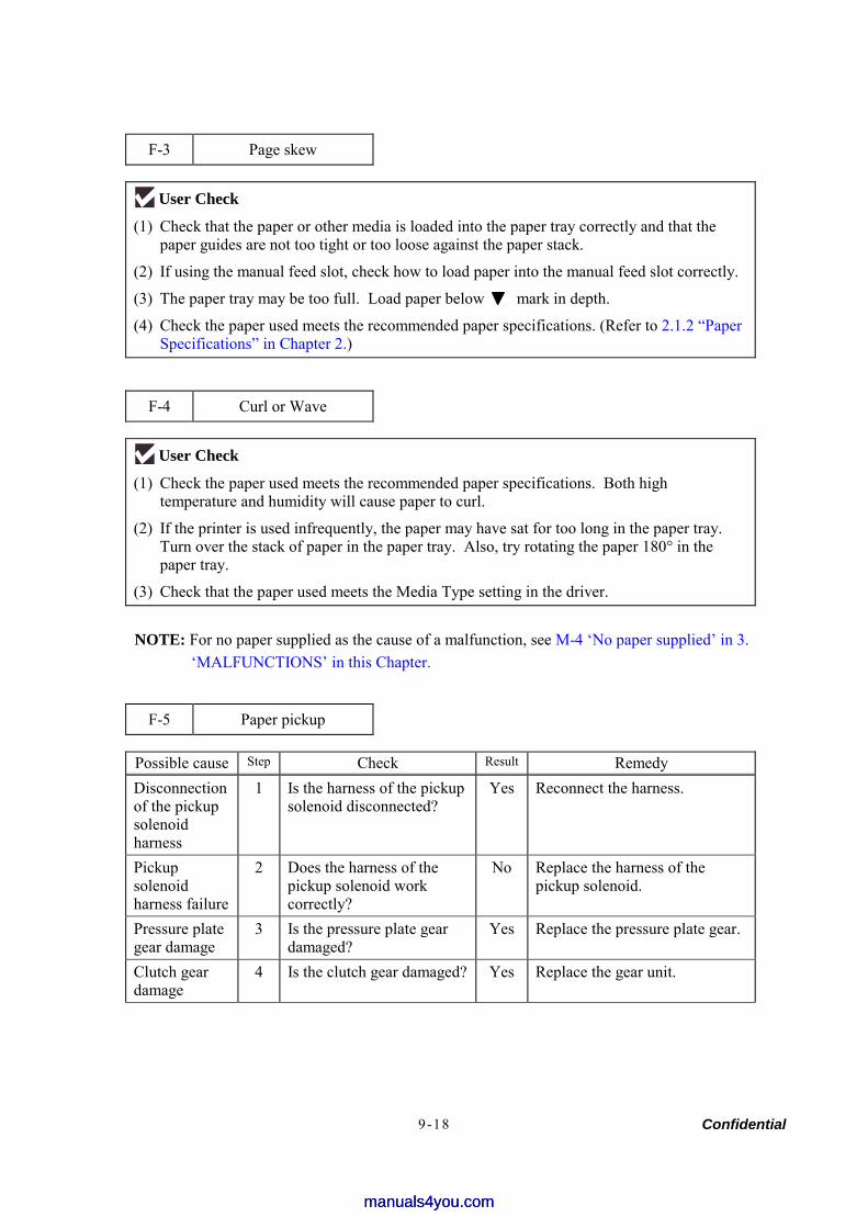
Confidential 9-18
F-3 Page skew
User Check (1) Check that the paper or other media is loaded into the paper tray correctly and that the
paper guides are not too tight or too loose against the paper stack.
(2) If using the manual feed slot, check how to load paper into the manual feed slot correctly.
(3) The paper tray may be too full. Load paper below mark in depth.
(4) Check the paper used meets the recommended paper specifications. (Refer to 2.1.2 “Paper Specifications” in Chapter 2.)
F-4 Curl or Wave
User Check (1) Check the paper used meets the recommended paper specifications. Both high
temperature and humidity will cause paper to curl.
(2) If the printer is used infrequently, the paper may have sat for too long in the paper tray. Turn over the stack of paper in the paper tray. Also, try rotating the paper 180° in the paper tray.
(3) Check that the paper used meets the Media Type setting in the driver.
NOTE: For no paper supplied as the cause of a malfunction, see M-4 ‘No paper supplied’ in 3. ‘MALFUNCTIONS’ in this Chapter.
F-5 Paper pickup
Possible cause Step Check Result Remedy Disconnection of the pickup solenoid harness
1 Is the harness of the pickup solenoid disconnected?
Yes Reconnect the harness.
Pickup solenoid harness failure
2 Does the harness of the pickup solenoid work correctly?
No Replace the harness of the pickup solenoid.
Pressure plate gear damage
3 Is the pressure plate gear damaged?
Yes Replace the pressure plate gear.
Clutch gear damage
4 Is the clutch gear damaged? Yes Replace the gear unit.
manuals4you.commanuals4you.com
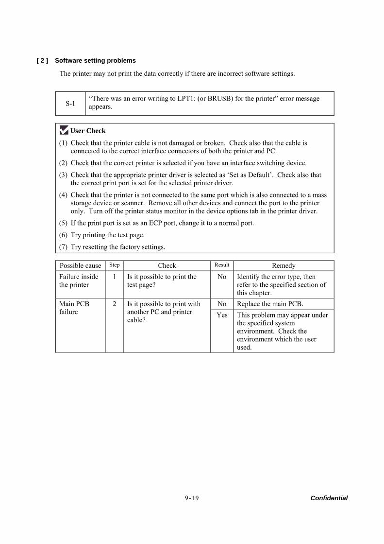
Confidential 9-19
[ 2 ] Software setting problems
The printer may not print the data correctly if there are incorrect software settings.
S-1 “There was an error writing to LPT1: (or BRUSB) for the printer” error message appears.
User Check (1) Check that the printer cable is not damaged or broken. Check also that the cable is
connected to the correct interface connectors of both the printer and PC.
(2) Check that the correct printer is selected if you have an interface switching device.
(3) Check that the appropriate printer driver is selected as ‘Set as Default’. Check also that the correct print port is set for the selected printer driver.
(4) Check that the printer is not connected to the same port which is also connected to a mass storage device or scanner. Remove all other devices and connect the port to the printer only. Turn off the printer status monitor in the device options tab in the printer driver.
(5) If the print port is set as an ECP port, change it to a normal port.
(6) Try printing the test page.
(7) Try resetting the factory settings.
Possible cause Step Check Result Remedy Failure inside the printer
1 Is it possible to print the test page?
No Identify the error type, then refer to the specified section of this chapter.
No Replace the main PCB. Main PCB failure
2 Is it possible to print with another PC and printer cable?
Yes This problem may appear under the specified system environment. Check the environment which the user used.
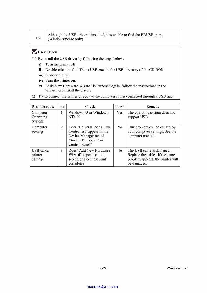
Confidential 9-20
S-2 Although the USB driver is installed, it is unable to find the BRUSB: port. (Windows98/Me only)
User Check (1) Re-install the USB driver by following the steps below;
i) Turn the printer off. ii) Double-click the file “Deins USB.exe” in the USB directory of the CD-ROM. iii) Re-boot the PC. iv) Turn the printer on. v) “Add New Hardware Wizard” is launched again, follow the instructions in the
Wizard tore-install the driver. (2) Try to connect the printer directly to the computer if it is connected through a USB hub.
Possible cause Step Check Result Remedy Computer Operating System
1 Windows 95 or Windows NT4.0?
Yes The operating system does not support USB.
Computer settings
2 Does ‘Universal Serial Bus Controllers’ appear in the Device Manager tab of ‘System Properties’ in Control Panel?
No This problem can be caused by your computer settings. See the computer manual.
USB cable/ printer damage
3 Does “Add New Hardware Wizard” appear on the screen or Does test print complete?
No The USB cable is damaged. Replace the cable. If the same problem appears, the printer will be damaged.
manuals4you.commanuals4you.com
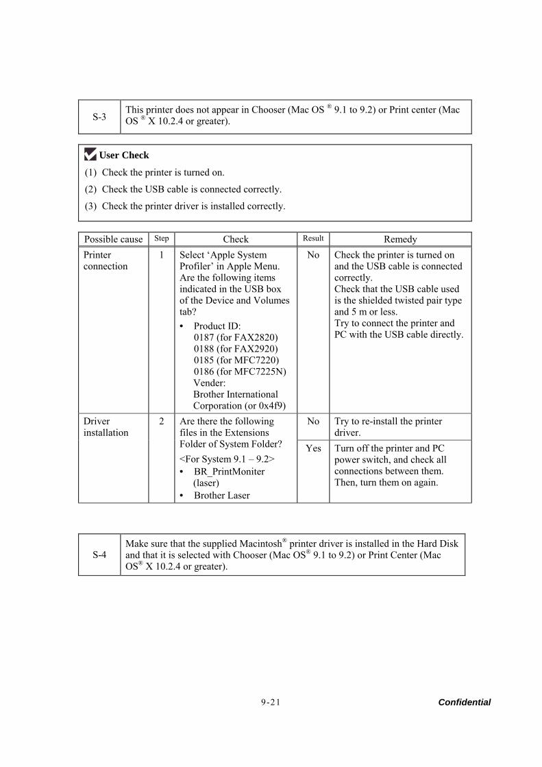
Confidential 9-21
S-3 This printer does not appear in Chooser (Mac OS ® 9.1 to 9.2) or Print center (Mac OS ® X 10.2.4 or greater).
User Check (1) Check the printer is turned on.
(2) Check the USB cable is connected correctly.
(3) Check the printer driver is installed correctly.
Possible cause Step Check Result Remedy Printer connection
1 Select ‘Apple System Profiler’ in Apple Menu. Are the following items indicated in the USB box of the Device and Volumes tab? • Product ID:
0187 (for FAX2820) 0188 (for FAX2920) 0185 (for MFC7220) 0186 (for MFC7225N) Vender: Brother International Corporation (or 0x4f9)
No Check the printer is turned on and the USB cable is connected correctly. Check that the USB cable used is the shielded twisted pair type and 5 m or less. Try to connect the printer and PC with the USB cable directly.
No Try to re-install the printer driver.
Driver installation
2 Are there the following files in the Extensions Folder of System Folder? <For System 9.1 – 9.2> • BR_PrintMoniter
(laser) • Brother Laser
Yes Turn off the printer and PC power switch, and check all connections between them. Then, turn them on again.
S-4 Make sure that the supplied Macintosh® printer driver is installed in the Hard Diskand that it is selected with Chooser (Mac OS® 9.1 to 9.2) or Print Center (Mac OS® X 10.2.4 or greater).
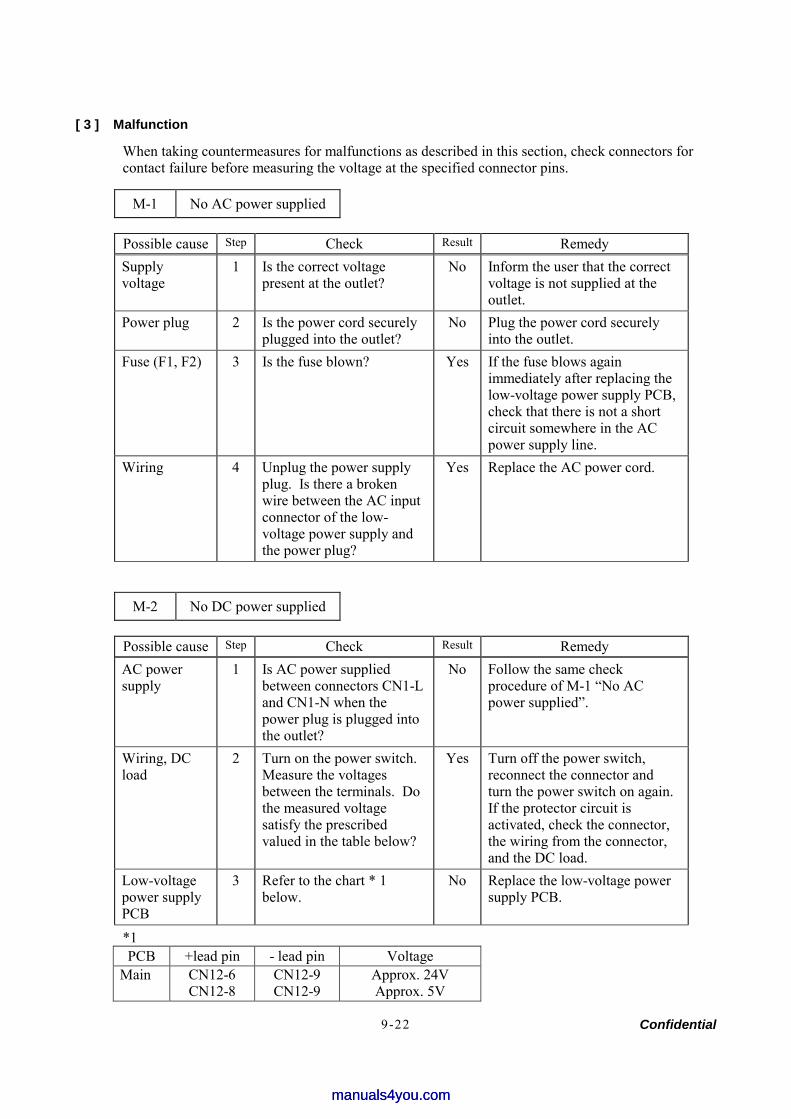
Confidential 9-22
[ 3 ] Malfunction
When taking countermeasures for malfunctions as described in this section, check connectors for contact failure before measuring the voltage at the specified connector pins.
M-1 No AC power supplied
Possible cause Step Check Result Remedy Supply voltage
1 Is the correct voltage present at the outlet?
No Inform the user that the correct voltage is not supplied at the outlet.
Power plug 2 Is the power cord securely plugged into the outlet?
No Plug the power cord securely into the outlet.
Fuse (F1, F2) 3 Is the fuse blown? Yes If the fuse blows again immediately after replacing the low-voltage power supply PCB, check that there is not a short circuit somewhere in the AC power supply line.
Wiring 4 Unplug the power supply plug. Is there a broken wire between the AC input connector of the low-voltage power supply and the power plug?
Yes Replace the AC power cord.
M-2 No DC power supplied
Possible cause Step Check Result Remedy AC power supply
1 Is AC power supplied between connectors CN1-L and CN1-N when the power plug is plugged into the outlet?
No Follow the same check procedure of M-1 “No AC power supplied”.
Wiring, DC load
2 Turn on the power switch. Measure the voltages between the terminals. Do the measured voltage satisfy the prescribed valued in the table below?
Yes Turn off the power switch, reconnect the connector and turn the power switch on again. If the protector circuit is activated, check the connector, the wiring from the connector, and the DC load.
Low-voltage power supply PCB
3 Refer to the chart * 1 below.
No Replace the low-voltage power supply PCB.
*1 PCB +lead pin - lead pin Voltage
Main CN12-6 CN12-8
CN12-9 CN12-9
Approx. 24V Approx. 5V
manuals4you.commanuals4you.com

Confidential 9-23
WARNING: If you analyze malfunctions with the power plug inserted into the power outlet, special caution should be exercised even if the power switch is OFF because it is a single pole switch
M-3 Main motor failure
Possible cause Step Check Result Remedy Failure of connector
1 Is the connection of connector CN9 on the main PCB correct?
No Reconnect the connector.
Main motor 2 Is the problem solved by replacing the main motor?
Yes Replace the main motor.
Main PCB 3 Is the problem solved by replacing the main PCB?
Yes Replace the main PCB.
M-4 No paper supplied
Possible cause Step Check Result Remedy Separation pad / pickup roller failure
1 Is the surface of the separation pad or the pickup roller dirty or worn out?
Yes 1) Clean the surface of the separation pad or pickup roller.
2) Replace the separation pad or pickup roller.
Failure of connector
2 Is the contact of the solenoid connector on the high voltage PCB good?
No Reconnect the connector.
HVPS circuit Yes Replace the HVPS. Paper pickup clutch solenoid
3 Set paper in the manual feed slot and make a test print. Does the voltage between pins 2 (SOLENOID) and 1 (24V) of the CN16 connector on the main PCB change from approx. 24V DC to 0V within the specified time?
No Replace the paper pickup clutch solenoid.
Main PCB 4 Is the problem solved by replacing the main PCB?
Yes Replace the main PCB.
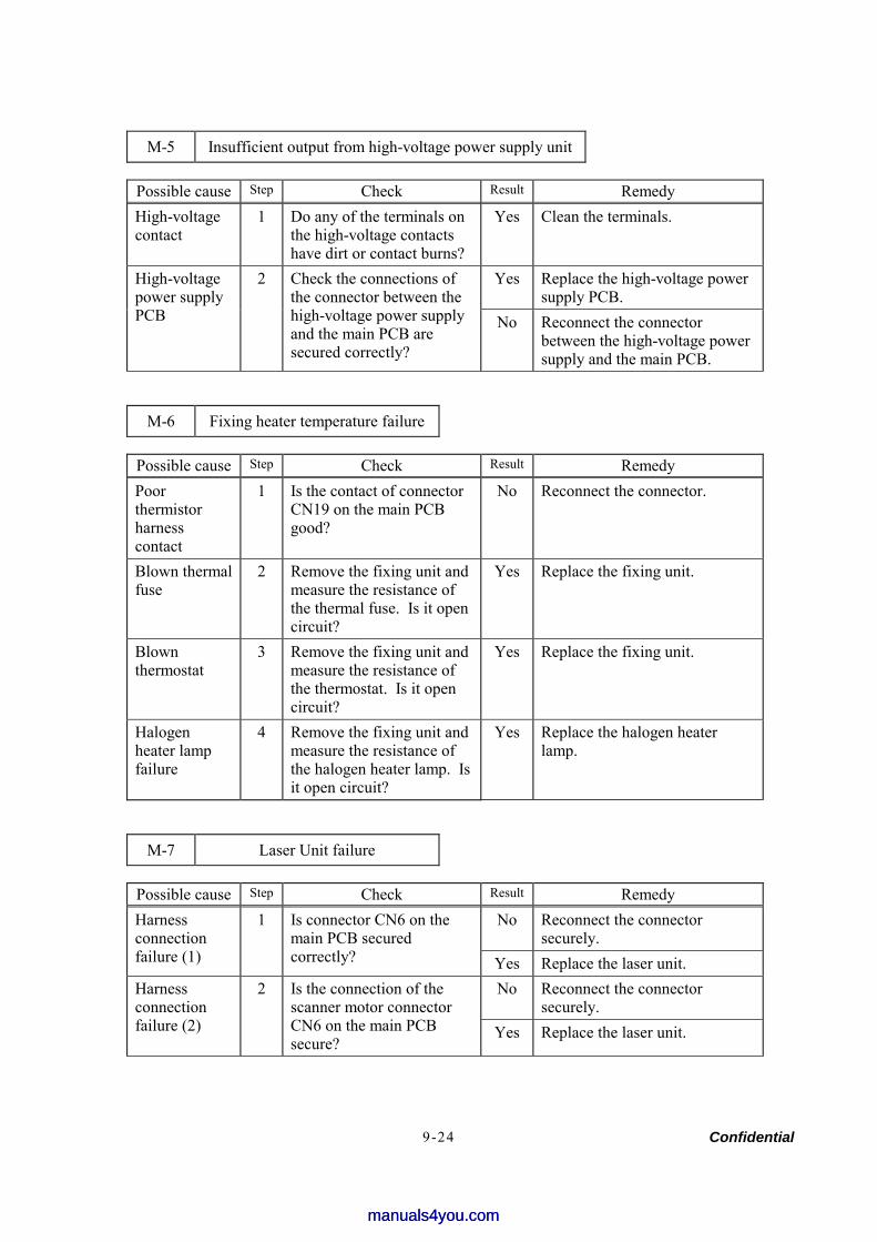
Confidential 9-24
M-5 Insufficient output from high-voltage power supply unit
Possible cause Step Check Result Remedy High-voltage contact
1 Do any of the terminals on the high-voltage contacts have dirt or contact burns?
Yes Clean the terminals.
Yes Replace the high-voltage power supply PCB.
High-voltage power supply PCB
2 Check the connections of the connector between the high-voltage power supply and the main PCB are secured correctly?
No Reconnect the connector between the high-voltage power supply and the main PCB.
M-6 Fixing heater temperature failure
Possible cause Step Check Result Remedy Poor thermistor harness contact
1 Is the contact of connector CN19 on the main PCB good?
No Reconnect the connector.
Blown thermal fuse
2 Remove the fixing unit and measure the resistance of the thermal fuse. Is it open circuit?
Yes Replace the fixing unit.
Blown thermostat
3 Remove the fixing unit and measure the resistance of the thermostat. Is it open circuit?
Yes Replace the fixing unit.
Halogen heater lamp failure
4 Remove the fixing unit and measure the resistance of the halogen heater lamp. Is it open circuit?
Yes Replace the halogen heater lamp.
M-7 Laser Unit failure
Possible cause Step Check Result Remedy No Reconnect the connector
securely. Harness connection failure (1)
1 Is connector CN6 on the main PCB secured correctly? Yes Replace the laser unit.
No Reconnect the connector securely.
Harness connection failure (2)
2 Is the connection of the scanner motor connector CN6 on the main PCB secure?
Yes Replace the laser unit.
manuals4you.commanuals4you.com
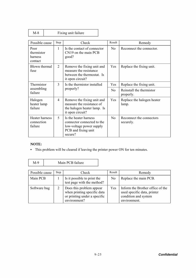
Confidential 9-25
M-8 Fixing unit failure
Possible cause Step Check Result Remedy Poor thermistor harness contact
1 Is the contact of connector CN19 on the main PCB good?
No Reconnect the connector.
Blown thermal fuse
2 Remove the fixing unit and measure the resistance between the thermostat. Is it open circuit?
Yes Replace the fixing unit.
Yes Replace the fixing unit. Thermistor assembling failure
3 Is the thermistor installed properly? No Reinstall the thermistor
properly. Halogen heater lamp failure
4 Remove the fixing unit and measure the resistance of the halogen heater lamp. Is it open circuit?
Yes Replace the halogen heater lamp.
Heater harness connection failure
5 Is the heater harness connector connected to the low-voltage power supply PCB and fixing unit secure?
No Reconnect the connectors securely.
NOTE: • This problem will be cleared if leaving the printer power ON for ten minutes.
M-9 Main PCB failure
Possible cause Step Check Result Remedy Main PCB 1 Is it possible to print the
test page with the method? No Replace the main PCB.
Software bug 2 Does this problem appear when printing specific data or printing under a specific environment?
Yes Inform the Brother office of the used specific data, printer condition and system environment.
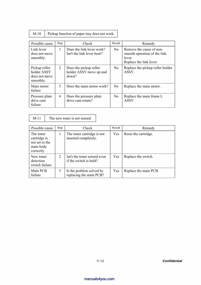
Confidential 9-26
M-10 Pickup function of paper tray does not work.
Possible cause Step Check Result Remedy Link lever does not move smoothly.
1 Does the link lever work? Isn't the link lever bent?
No Remove the cause of non-smooth operation of the link lever. Replace the link lever.
Pickup roller holder ASSY does not move smoothly.
2 Does the pickup roller holder ASSY move up and down?
No Replace the pickup roller holder ASSY.
Main motor failure
3 Does the main motor work? No Replace the main motor.
Pressure plate drive cam failure
4 Does the pressure plate drive cam rotate?
No Replace the main frame L ASSY.
M-11 The new toner is not sensed.
Possible cause Step Check Result Remedy The toner cartridge is not set to the main body correctly
1 The toner cartridge is not inserted completely.
Yes Reset the cartridge.
New toner detection switch failure
2 Isn't the toner sensed even if the switch is held?
Yes Replace the switch.
Main PCB failure
3 Is the problem solved by replacing the main PCB?
Yes Replace the main PCB.
manuals4you.commanuals4you.com
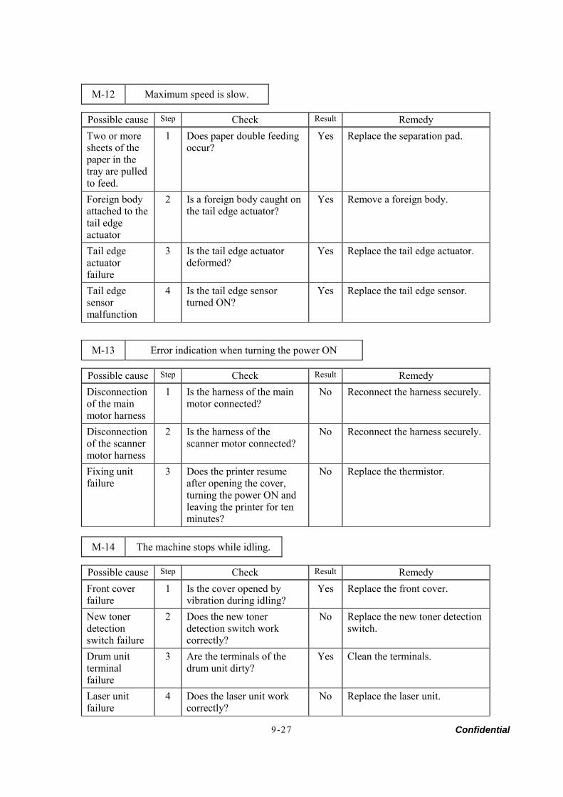
Confidential 9-27
M-12 Maximum speed is slow.
Possible cause Step Check Result Remedy Two or more sheets of the paper in the tray are pulled to feed.
1 Does paper double feeding occur?
Yes Replace the separation pad.
Foreign body attached to the tail edge actuator
2 Is a foreign body caught on the tail edge actuator?
Yes Remove a foreign body.
Tail edge actuator failure
3 Is the tail edge actuator deformed?
Yes Replace the tail edge actuator.
Tail edge sensor malfunction
4 Is the tail edge sensor turned ON?
Yes Replace the tail edge sensor.
M-13 Error indication when turning the power ON
Possible cause Step Check Result Remedy Disconnection of the main motor harness
1 Is the harness of the main motor connected?
No Reconnect the harness securely.
Disconnection of the scanner motor harness
2 Is the harness of the scanner motor connected?
No Reconnect the harness securely.
Fixing unit failure
3 Does the printer resume after opening the cover, turning the power ON and leaving the printer for ten minutes?
No Replace the thermistor.
M-14 The machine stops while idling.
Possible cause Step Check Result Remedy Front cover failure
1 Is the cover opened by vibration during idling?
Yes Replace the front cover.
New toner detection switch failure
2 Does the new toner detection switch work correctly?
No Replace the new toner detection switch.
Drum unit terminal failure
3 Are the terminals of the drum unit dirty?
Yes Clean the terminals.
Laser unit failure
4 Does the laser unit work correctly?
No Replace the laser unit.
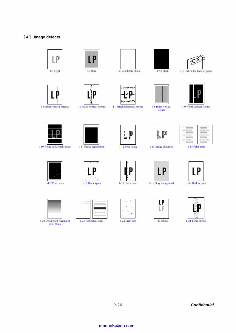
Confidential 9-28
[ 4 ] Image defects
1-1 Light 1-2 Dark 1-3 Completely blank 1-4 All black 1-5 Dirt on the back of paper
1-6 Black vertical streaks 1-6 Black vertical streaks 1-7 Black horizontal stripes 1-8 Black vertical
streaks 1-9 White vertical streaks
Print out test print out test print out test Print out test print o
Print out test print out test print out test Print out test print o
Print out test print o
Print out test print out test print out test Print out test print o
Print out test print out test print out test Print out test print o
Print out test print o
Print out test print out test print out test Print out test print o
Print out test print out test print out test Print out test print o
Print out test print o
Print out test print out test print out test Print out test print o
Print out test print out test print out test Print out test print o
Print out test print o
Print out test print out test print out test Print out test print o
Print out test print out test print out test Print out test print o
Print out test print o
Print out test print out test print out test Print out test print o
Print out test print out test print out test Print out test print o
Print out test print o
Print out test print out test print out test Print out test print o
Print out test print out test print out test Print out test print o
Print out test print o
Print out test print out test print out test Print out test print o
Print out test print out test print out test Print out test print o
Print out test print o
Print out test print out test print out test Print out test print o
Print out test print out test print out test Print out test print o
Print out test print o
Print out test print out test print out test Print out test print o
Print out test print out test print out test Print out test print o
Print out test print o
Print out test print out test print out test Print out test print o
Print out test print out test print out test Print out test print o
Print out test print o
Print out test print out test print out test Print out test print o
Print out test print out test print out test Print out test print o
Print out test print o
Print out test print out test print out test Print out test print o
Print out test print out test print out test Print out test print o
Print out test print o
Print out test print out test print out test Print out test print o
Print out test print out test print out test Print out test print o
Print out test print o
Print out test print out test print out test Print out test print o
Print out test print out test print out test Print out test print o
Print out test print o
Print out test print out test print out test Print out test print o
Print out test print out test print out test Print out test print o
Print out test print o
Print out test print out test print out test Print out test print o
Print out test print out test print out test Print out test print o
Print out test print o
Print out test print out test print out test Print out test print o
Print out test print out test print out test Print out test print o
Print out test print o
Print out test print out test print out test Print out test print o
Print out test print out test print out test Print out test print o
Print out test print o
Print out test print out test print out test Print out test print o
Print out test print out test print out test Print out test print o
Print out test print o
Print out test print out test print out test Print out test print o
Print out test print out test print out test Print out test print o
Print out test print o
Print out test print out test print out test Print out test print o
Print out test print out test print out test Print out test print o
Print out test print o
Print out test print out test print out test Print out test print o
Print out test print out test print out test Print out test print o
Print out test print o
Print out test print out test print out test Print out test print o
Print out test print out test print out test Print out test print o
Print out test print o
Print out test print out test print out test Print out test print o
Print out test print out test print out test Print out test print o
Print out test print o
Print out test print out test print out test Print out test print o
Print out test print out test print out test Print out test print o
Print out test print o
1-10 White horizontal streaks 1-11 Faulty registration 1-12 Poor fixing 1-13 Image distortion 1-14 Faint print
1-15 White spots 1-16 Black spots 1-17 Black band 1-18 Gray background 1-19 Hollow print
1-20 Downward fogging of
solid black 1-21 Horizontal lines 1-22 Light rain 1-23 Ghost 1-24 Toner specks
manuals4you.commanuals4you.com
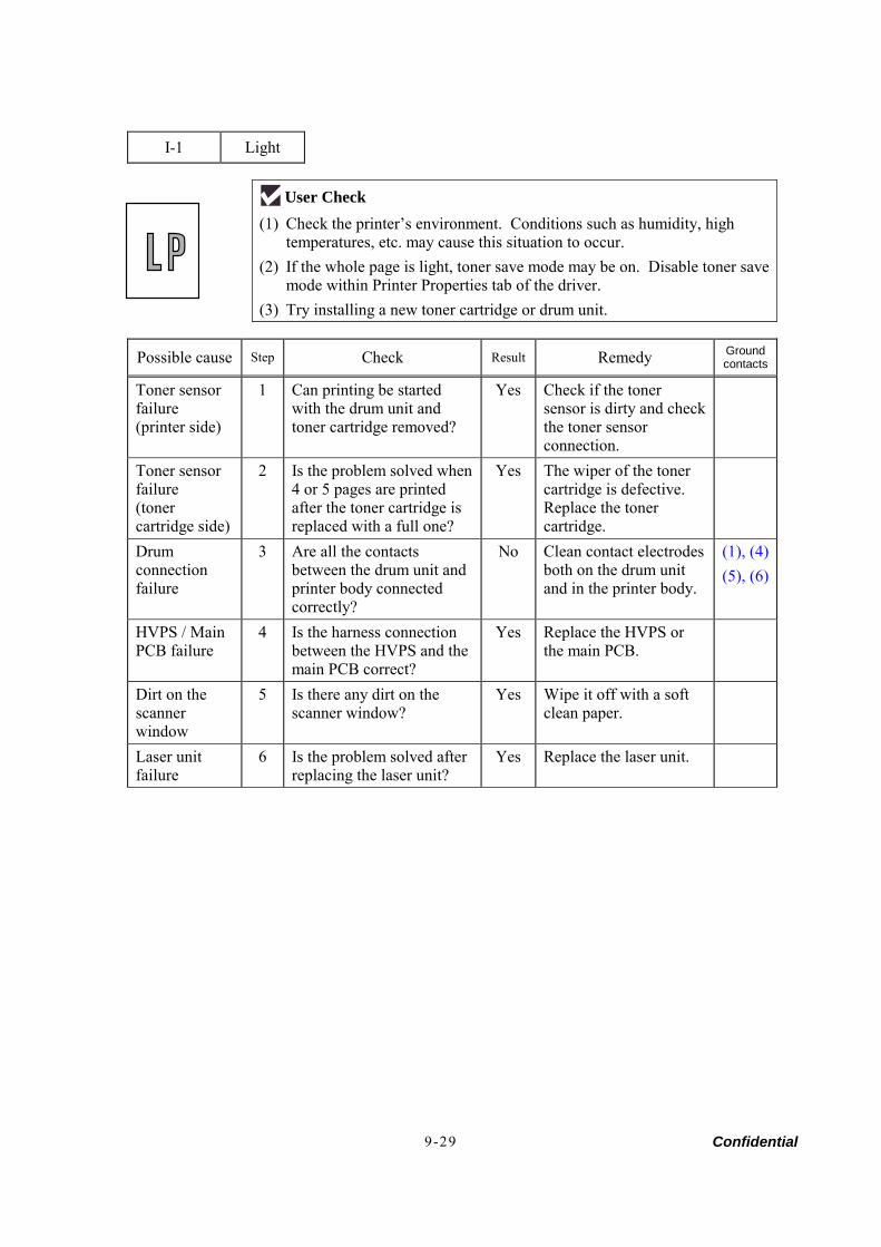
Confidential 9-29
I-1 Light
User Check (1) Check the printer’s environment. Conditions such as humidity, high
temperatures, etc. may cause this situation to occur. (2) If the whole page is light, toner save mode may be on. Disable toner save
mode within Printer Properties tab of the driver. (3) Try installing a new toner cartridge or drum unit.
Possible cause Step Check Result Remedy Ground contacts
Toner sensor failure (printer side)
1 Can printing be started with the drum unit and toner cartridge removed?
Yes Check if the toner sensor is dirty and check the toner sensor connection.
Toner sensor failure (toner cartridge side)
2 Is the problem solved when 4 or 5 pages are printed after the toner cartridge is replaced with a full one?
Yes The wiper of the toner cartridge is defective. Replace the toner cartridge.
Drum connection failure
3 Are all the contacts between the drum unit and printer body connected correctly?
No Clean contact electrodes both on the drum unit and in the printer body.
(1), (4) (5), (6)
HVPS / Main PCB failure
4 Is the harness connection between the HVPS and the main PCB correct?
Yes Replace the HVPS or the main PCB.
Dirt on the scanner window
5 Is there any dirt on the scanner window?
Yes Wipe it off with a soft clean paper.
Laser unit failure
6 Is the problem solved after replacing the laser unit?
Yes Replace the laser unit.
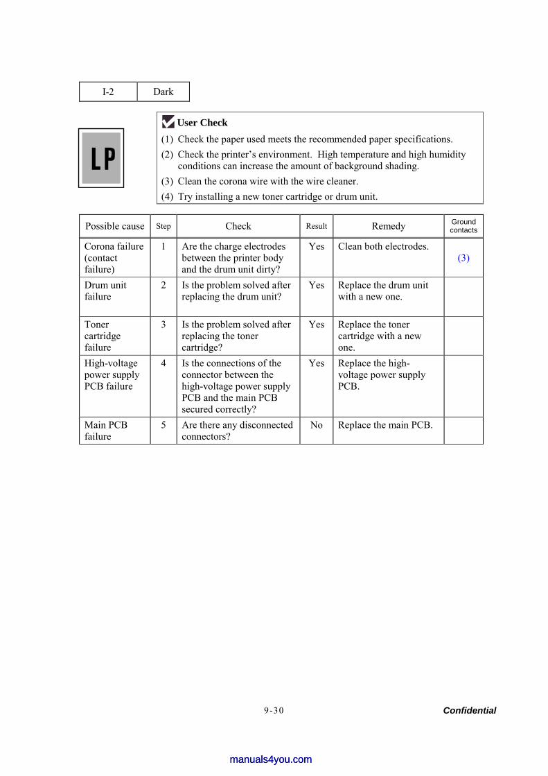
Confidential 9-30
I-2 Dark
User Check (1) Check the paper used meets the recommended paper specifications. (2) Check the printer’s environment. High temperature and high humidity
conditions can increase the amount of background shading. (3) Clean the corona wire with the wire cleaner. (4) Try installing a new toner cartridge or drum unit.
Possible cause Step Check Result Remedy Ground contacts
Corona failure (contact failure)
1 Are the charge electrodes between the printer body and the drum unit dirty?
Yes Clean both electrodes. (3)
Drum unit failure
2 Is the problem solved after replacing the drum unit?
Yes Replace the drum unit with a new one.
Toner cartridge failure
3 Is the problem solved after replacing the toner cartridge?
Yes Replace the toner cartridge with a new one.
High-voltage power supply PCB failure
4 Is the connections of the connector between the high-voltage power supply PCB and the main PCB secured correctly?
Yes Replace the high-voltage power supply PCB.
Main PCB failure
5 Are there any disconnected connectors?
No Replace the main PCB.
manuals4you.commanuals4you.com
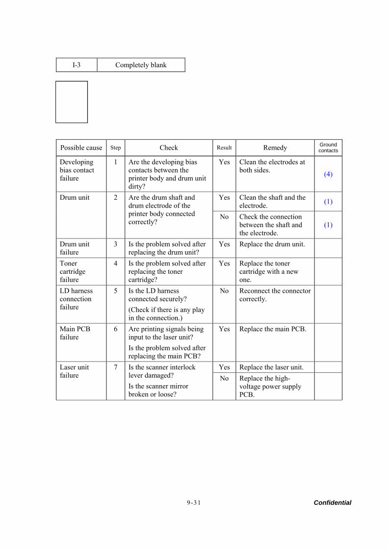
Confidential 9-31
I-3 Completely blank
Possible cause Step Check Result Remedy Ground contacts
Developing bias contact failure
1 Are the developing bias contacts between the printer body and drum unit dirty?
Yes Clean the electrodes at both sides. (4)
Yes Clean the shaft and the electrode. (1) Drum unit 2 Are the drum shaft and
drum electrode of the printer body connected correctly?
No Check the connection between the shaft and the electrode.
(1)
Drum unit failure
3 Is the problem solved after replacing the drum unit?
Yes Replace the drum unit.
Toner cartridge failure
4 Is the problem solved after replacing the toner cartridge?
Yes Replace the toner cartridge with a new one.
LD harness connection failure
5 Is the LD harness connected securely? (Check if there is any play in the connection.)
No Reconnect the connector correctly.
Main PCB failure
6 Are printing signals being input to the laser unit? Is the problem solved after replacing the main PCB?
Yes Replace the main PCB.
Yes Replace the laser unit. Laser unit failure
7 Is the scanner interlock lever damaged? Is the scanner mirror broken or loose?
No Replace the high-voltage power supply PCB.
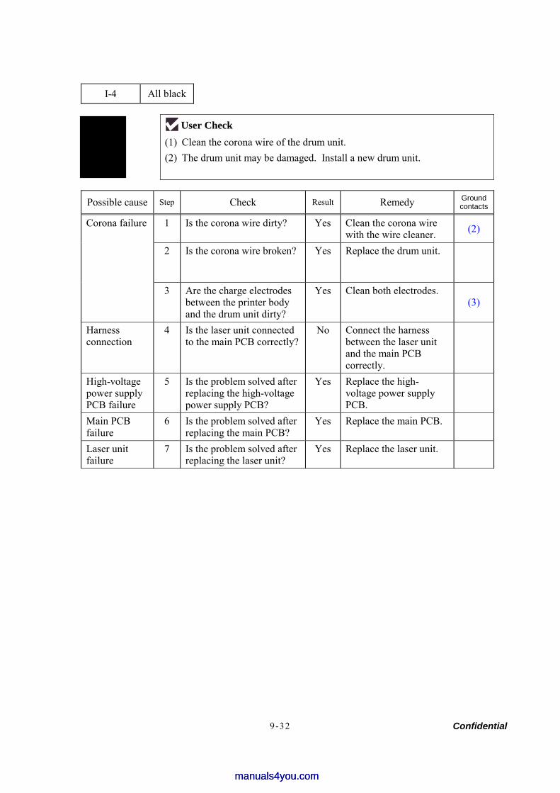
Confidential 9-32
I-4 All black
User Check (1) Clean the corona wire of the drum unit. (2) The drum unit may be damaged. Install a new drum unit.
Possible cause Step Check Result Remedy Ground contacts
1 Is the corona wire dirty? Yes Clean the corona wire with the wire cleaner. (2)
2 Is the corona wire broken? Yes Replace the drum unit.
Corona failure
3 Are the charge electrodes between the printer body and the drum unit dirty?
Yes Clean both electrodes. (3)
Harness connection
4 Is the laser unit connected to the main PCB correctly?
No Connect the harness between the laser unit and the main PCB correctly.
High-voltage power supply PCB failure
5 Is the problem solved after replacing the high-voltage power supply PCB?
Yes Replace the high-voltage power supply PCB.
Main PCB failure
6 Is the problem solved after replacing the main PCB?
Yes Replace the main PCB.
Laser unit failure
7 Is the problem solved after replacing the laser unit?
Yes Replace the laser unit.
manuals4you.commanuals4you.com
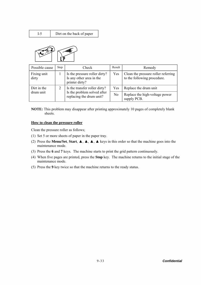
Confidential 9-33
I-5 Dirt on the back of paper
Possible cause Step Check Result Remedy
Fixing unit dirty
1 Is the pressure roller dirty? Is any other area in the printer dirty?
Yes Clean the pressure roller referring to the following procedure.
Yes Replace the drum unit Dirt in the drum unit
2 Is the transfer roller dirty? Is the problem solved after replacing the drum unit? No Replace the high-voltage power
supply PCB.
NOTE: This problem may disappear after printing approximately 10 pages of completely blank sheets.
How to clean the pressure roller
Clean the pressure roller as follows; (1) Set 5 or more sheets of paper in the paper tray. (2) Press the Menu/Set, Start, , , , keys in this order so that the machine goes into the
maintenance mode. (3) Press the 6 and 7 keys. The machine starts to print the grid pattern continuously. (4) When five pages are printed, press the Stop key. The machine returns to the initial stage of the
maintenance mode. (5) Press the 9 key twice so that the machine returns to the ready status.
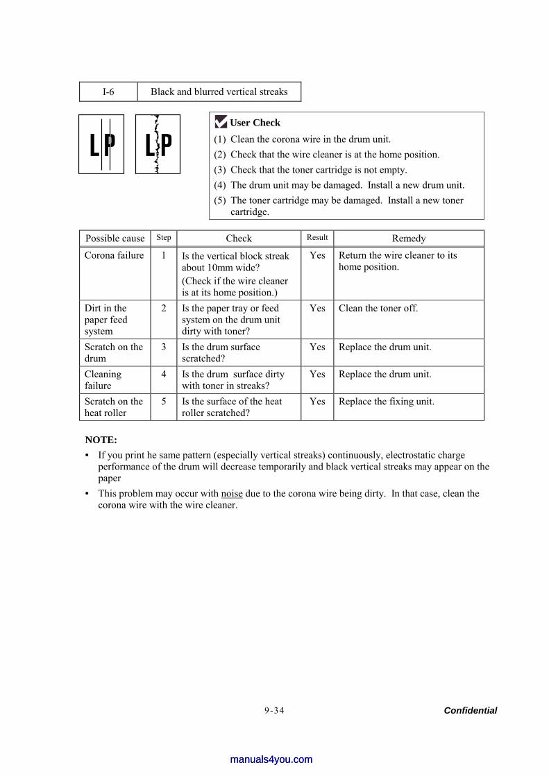
Confidential 9-34
I-6 Black and blurred vertical streaks
User Check (1) Clean the corona wire in the drum unit. (2) Check that the wire cleaner is at the home position. (3) Check that the toner cartridge is not empty. (4) The drum unit may be damaged. Install a new drum unit. (5) The toner cartridge may be damaged. Install a new toner
cartridge.
Possible cause Step Check Result Remedy
Corona failure 1 Is the vertical block streak about 10mm wide? (Check if the wire cleaner is at its home position.)
Yes Return the wire cleaner to its home position.
Dirt in the paper feed system
2 Is the paper tray or feed system on the drum unit dirty with toner?
Yes Clean the toner off.
Scratch on the drum
3 Is the drum surface scratched?
Yes Replace the drum unit.
Cleaning failure
4 Is the drum surface dirty with toner in streaks?
Yes Replace the drum unit.
Scratch on the heat roller
5 Is the surface of the heat roller scratched?
Yes Replace the fixing unit.
NOTE: • If you print he same pattern (especially vertical streaks) continuously, electrostatic charge
performance of the drum will decrease temporarily and black vertical streaks may appear on the paper
• This problem may occur with noise due to the corona wire being dirty. In that case, clean the corona wire with the wire cleaner.
manuals4you.commanuals4you.com
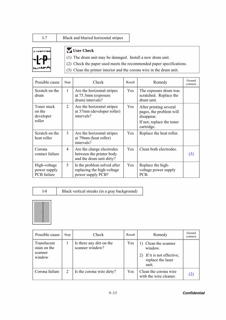
Confidential 9-35
I-7 Black and blurred horizontal stripes
User Check (1) The drum unit may be damaged. Install a new drum unit. (2) Check the paper used meets the recommended paper specifications. (3) Clean the printer interior and the corona wire in the drum unit.
Possible cause Step Check Result Remedy Ground contacts
Scratch on the drum
1 Are the horizontal stripes at 75.3mm (exposure drum) intervals?
Yes The exposure drum was scratched. Replace the drum unit.
Toner stuck on the developer roller
2 Are the horizontal stripes at 37mm (developer roller) intervals?
Yes After printing several pages, the problem will disappear. If not, replace the toner cartridge.
Scratch on the heat roller
3 Are the horizontal stripes at 79mm (heat roller) intervals?
Yes Replace the heat roller.
Corona contact failure
4 Are the charge electrodes between the printer body and the drum unit dirty?
Yes Clean both electrodes. (3)
High-voltage power supply PCB failure
5 Is the problem solved after replacing the high-voltage power supply PCB?
Yes Replace the high-voltage power supply PCB.
I-8 Black vertical streaks (in a gray background)
Possible cause Step Check Result Remedy Ground contacts
Translucent stain on the scanner window
1 Is there any dirt on the scanner window?
Yes 1) Clean the scanner window.
2) If it is not effective, replace the laser unit.
Corona failure 2 Is the corona wire dirty? Yes Clean the corona wire with the wire cleaner. (2)
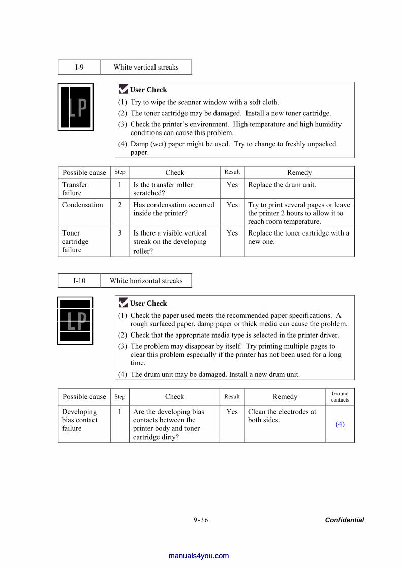
Confidential 9-36
I-9 White vertical streaks
User Check (1) Try to wipe the scanner window with a soft cloth. (2) The toner cartridge may be damaged. Install a new toner cartridge. (3) Check the printer’s environment. High temperature and high humidity
conditions can cause this problem. (4) Damp (wet) paper might be used. Try to change to freshly unpacked
paper.
Possible cause Step Check Result Remedy
Transfer failure
1 Is the transfer roller scratched?
Yes Replace the drum unit.
Condensation 2 Has condensation occurred inside the printer?
Yes Try to print several pages or leave the printer 2 hours to allow it to reach room temperature.
Toner cartridge failure
3 Is there a visible vertical streak on the developing roller?
Yes Replace the toner cartridge with a new one.
I-10 White horizontal streaks
User Check (1) Check the paper used meets the recommended paper specifications. A
rough surfaced paper, damp paper or thick media can cause the problem. (2) Check that the appropriate media type is selected in the printer driver. (3) The problem may disappear by itself. Try printing multiple pages to
clear this problem especially if the printer has not been used for a long time.
(4) The drum unit may be damaged. Install a new drum unit.
Possible cause Step Check Result Remedy Ground contacts
Developing bias contact failure
1 Are the developing bias contacts between the printer body and toner cartridge dirty?
Yes Clean the electrodes at both sides. (4)
manuals4you.commanuals4you.com
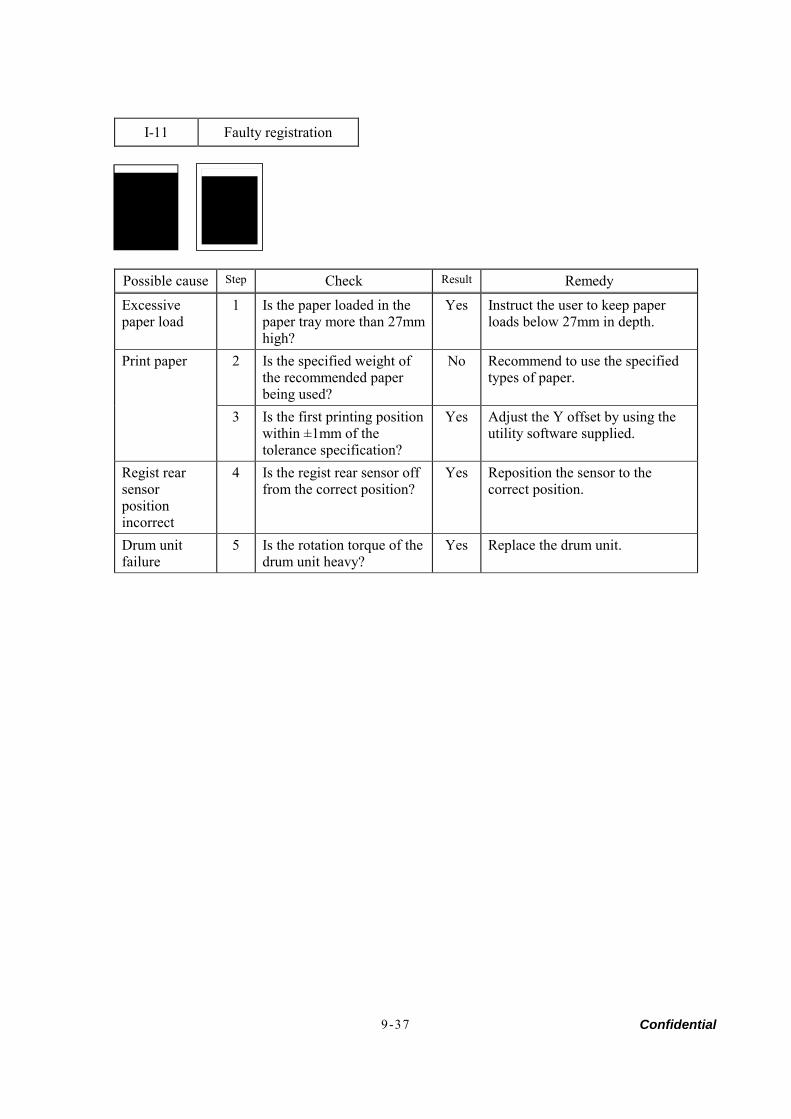
Confidential 9-37
I-11 Faulty registration
Possible cause Step Check Result Remedy
Excessive paper load
1 Is the paper loaded in the paper tray more than 27mm high?
Yes Instruct the user to keep paper loads below 27mm in depth.
2 Is the specified weight of the recommended paper being used?
No Recommend to use the specified types of paper.
Print paper
3 Is the first printing position within ±1mm of the tolerance specification?
Yes Adjust the Y offset by using the utility software supplied.
Regist rear sensor position incorrect
4 Is the regist rear sensor off from the correct position?
Yes Reposition the sensor to the correct position.
Drum unit failure
5 Is the rotation torque of the drum unit heavy?
Yes Replace the drum unit.
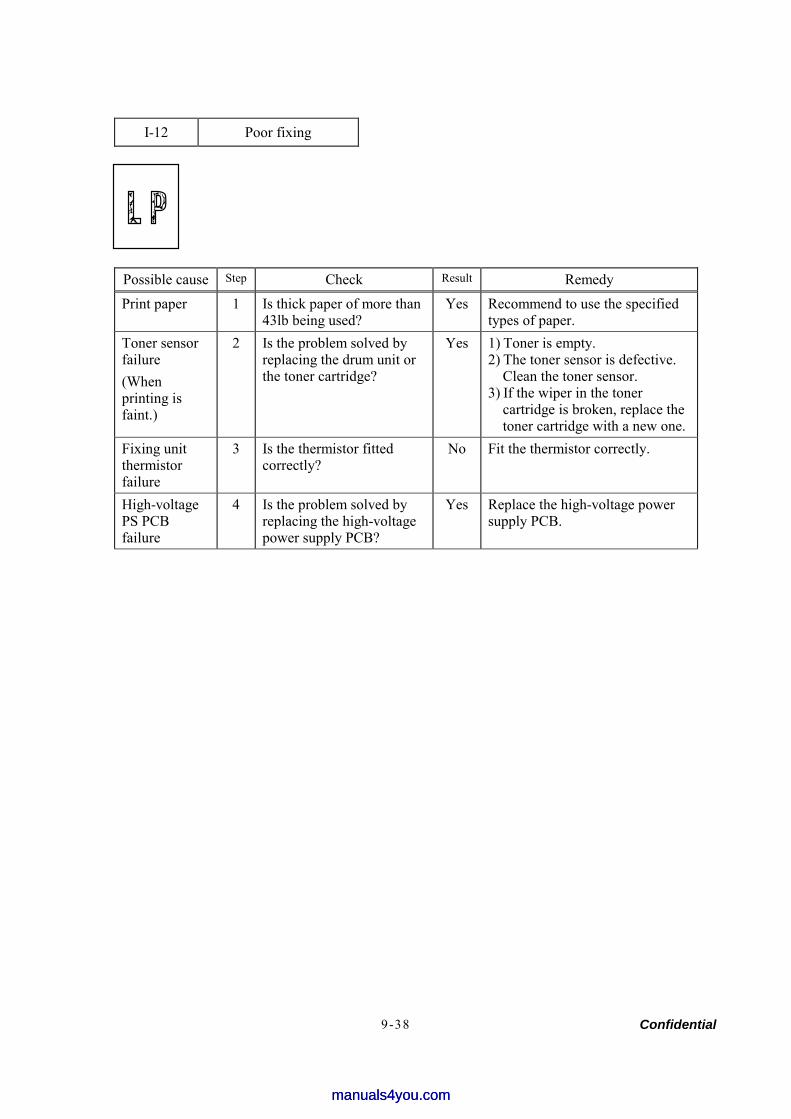
Confidential 9-38
I-12 Poor fixing
Possible cause Step Check Result Remedy
Print paper 1 Is thick paper of more than 43lb being used?
Yes Recommend to use the specified types of paper.
Toner sensor failure (When printing is faint.)
2 Is the problem solved by replacing the drum unit or the toner cartridge?
Yes 1) Toner is empty. 2) The toner sensor is defective.
Clean the toner sensor. 3) If the wiper in the toner
cartridge is broken, replace the toner cartridge with a new one.
Fixing unit thermistor failure
3 Is the thermistor fitted correctly?
No Fit the thermistor correctly.
High-voltage PS PCB failure
4 Is the problem solved by replacing the high-voltage power supply PCB?
Yes Replace the high-voltage power supply PCB.
manuals4you.commanuals4you.com
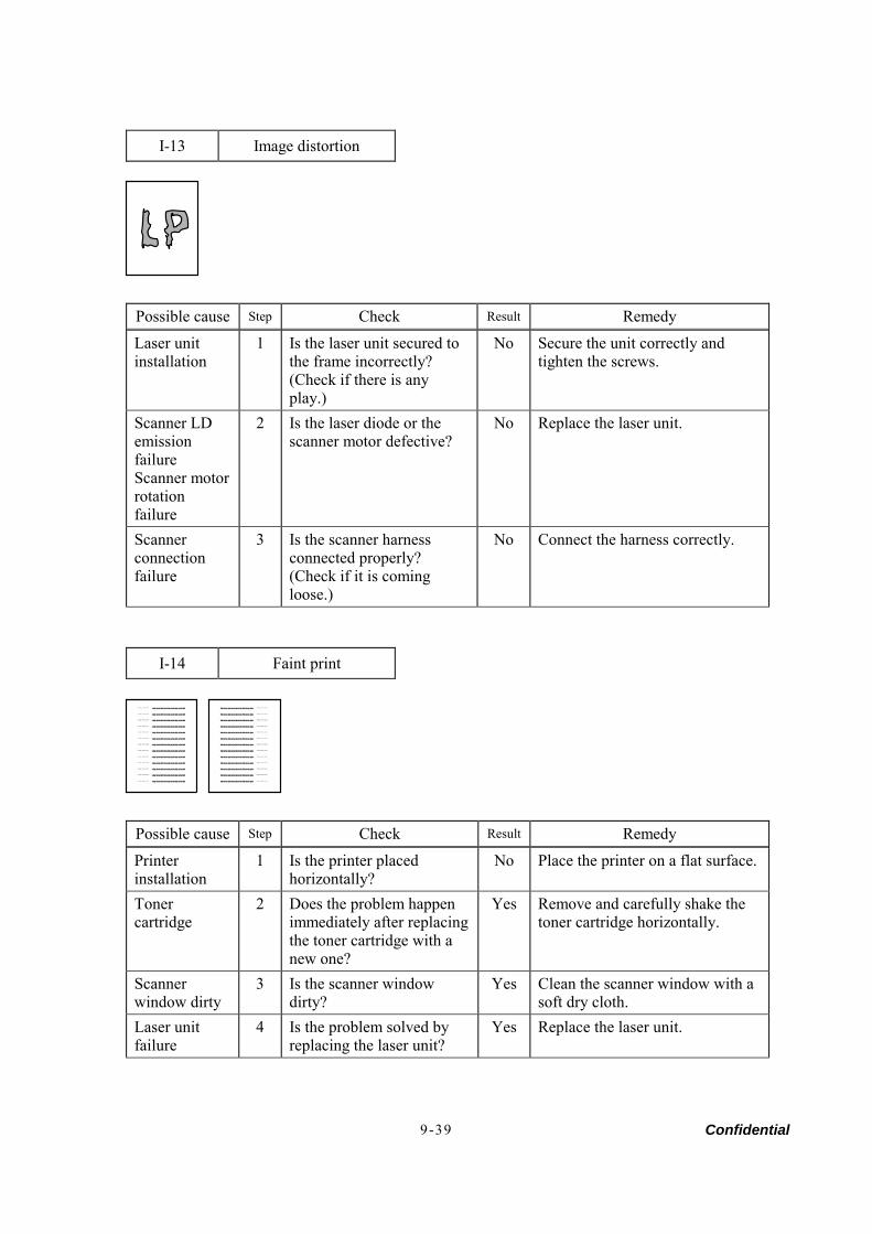
Confidential 9-39
I-13 Image distortion
Possible cause Step Check Result Remedy
Laser unit installation
1 Is the laser unit secured to the frame incorrectly? (Check if there is any play.)
No Secure the unit correctly and tighten the screws.
Scanner LD emission failure Scanner motor rotation failure
2 Is the laser diode or the scanner motor defective?
No Replace the laser unit.
Scanner connection failure
3 Is the scanner harness connected properly? (Check if it is coming loose.)
No Connect the harness correctly.
I-14 Faint print
Print out test print out test print out test Print out test print oPrint out test print out test print out test Print out test print o
Print out test print o
Print out test print out test print out test Print out test print oPrint out test print out test print out test Print out test print o Print out test print o
Print out test print out test print out test Print out test print oPrint out test print out test print out test Print out test print o Print out test print o
Print out test print out test print out test Print out test print oPrint out test print out test print out test Print out test print o Print out test print o
Print out test print out test print out test Print out test print oPrint out test print out test print out test Print out test print o Print out test print o
Print out test print out test print out test Print out test print oPrint out test print out test print out test Print out test print o Print out test print o
Print out test print out test print out test Print out test print oPrint out test print out test print out test Print out test print o Print out test print o
Print out test print out test print out test Print out test print oPrint out test print out test print out test Print out test print o Print out test print o
Print out test print out test print out test Print out test print oPrint out test print out test print out test Print out test print o Print out test print o
Print out test print out test print out test Print out test print oPrint out test print out test print out test Print out test print o Print out test print o
Print out test print out test print out test Print out test print oPrint out test print out test print out test Print out test print o Print out test print o
Print out test print out test print out test Print out test print oPrint out test print out test print out test Print out test print o Print out test print o
Print out test print out test print out test Print out test print oPrint out test print out test print out test Print out test print o Print out test print o
Print out test print out test print out test Print out test print oPrint out test print out test print out test Print out test print o
Print out test print o
Print out test print out test print out test Print out test print o Print out test print out test print out test Print out test print oPrint out test print o
Print out test print out test print out test Print out test print o Print out test print out test print out test Print out test print oPrint out test print o
Print out test print out test print out test Print out test print o Print out test print out test print out test Print out test print oPrint out test print o
Print out test print out test print out test Print out test print o Print out test print out test print out test Print out test print oPrint out test print o
Print out test print out test print out test Print out test print o Print out test print out test print out test Print out test print oPrint out test print o
Print out test print out test print out test Print out test print o Print out test print out test print out test Print out test print oPrint out test print o
Print out test print out test print out test Print out test print o Print out test print out test print out test Print out test print oPrint out test print o
Print out test print out test print out test Print out test print o Print out test print out test print out test Print out test print oPrint out test print o
Print out test print out test print out test Print out test print o Print out test print out test print out test Print out test print oPrint out test print o
Print out test print out test print out test Print out test print o Print out test print out test print out test Print out test print oPrint out test print o
Print out test print out test print out test Print out test print o Print out test print out test print out test Print out test print oPrint out test print o
Print out test print out test print out test Print out test print o Print out test print out test print out test Print out test print oPrint out test print o
Possible cause Step Check Result Remedy
Printer installation
1 Is the printer placed horizontally?
No Place the printer on a flat surface.
Toner cartridge
2 Does the problem happen immediately after replacing the toner cartridge with a new one?
Yes Remove and carefully shake the toner cartridge horizontally.
Scanner window dirty
3 Is the scanner window dirty?
Yes Clean the scanner window with a soft dry cloth.
Laser unit failure
4 Is the problem solved by replacing the laser unit?
Yes Replace the laser unit.

Confidential 9-40
I-15 White spots
User Check (1) If the problem is not solved after printing a few pages, the drum unit may
have glue from label stock on the exposure drum surface. Refer to Step 1 in the table below and NOTE in the next page.
(2) The drum unit may be damaged. Install a new drum unit.
Possible cause Step Check Result Remedy
1 Are the white spot at 75.3mm intervals?
Yes 1) If toner or glue remains stuck, wipe it off gently with a cotton swab. (Refer to NOTE in the next page.)
2) If the drum surface is scratched, replace the drum unit.
Drum unit failure
2 Is the problem solved after replacing the drum unit?
No Replace the drum unit.
No toner 3 Is the toner in the toner cartridge almost empty?
Yes Replace the toner cartridge with a new one.
Print paper 4 Is the problem solved after changing to specified freshly unpacked paper?
No Damp (wet) paper might be used. Recommend to change freshly unpacked paper.
Environment 5 Does the problem still appear after the printer has warmed up?
Yes 1) Replace the drum unit. 2) Advise the user of the specified
print environment
manuals4you.commanuals4you.com

Confidential 9-41
NOTE: Clean the drum unit as follows.
(1) Remove the toner cartridge from the drum unit. Place the printing samples in front of the drum unit, and find the exact position of the image defect.
(2) Turn the drum gear by hand while looking at the surface of the exposure drum.
(3) Wipe the surface of the exposure drum with a cotton swab until the dust or paper powder on the surface comes off.
CAUTION: • Do not wipe the surface of the exposure drum with something sharp. (ball-point pen etc.) • Use cleaning liquid which is a 50-50 mixture of ethyl alcohol and pure water.
Drum unit
Printing sample
Position of smudge on the drum
75.3mm interval
Exposure drum
Exposure drum
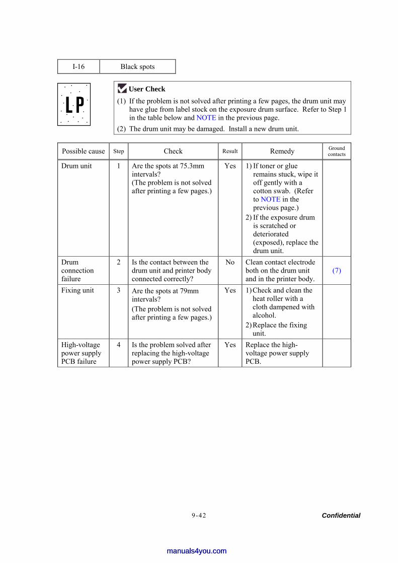
Confidential 9-42
I-16 Black spots
User Check (1) If the problem is not solved after printing a few pages, the drum unit may
have glue from label stock on the exposure drum surface. Refer to Step 1 in the table below and NOTE in the previous page.
(2) The drum unit may be damaged. Install a new drum unit.
Possible cause Step Check Result Remedy Ground contacts
Drum unit 1 Are the spots at 75.3mm intervals? (The problem is not solved after printing a few pages.)
Yes 1) If toner or glue remains stuck, wipe it off gently with a cotton swab. (Refer to NOTE in the previous page.)
2) If the exposure drum is scratched or deteriorated (exposed), replace the drum unit.
Drum connection failure
2 Is the contact between the drum unit and printer body connected correctly?
No Clean contact electrode both on the drum unit and in the printer body.
(7)
Fixing unit 3 Are the spots at 79mm intervals? (The problem is not solved after printing a few pages.)
Yes 1) Check and clean the heat roller with a cloth dampened with alcohol.
2) Replace the fixing unit.
High-voltage power supply PCB failure
4 Is the problem solved after replacing the high-voltage power supply PCB?
Yes Replace the high-voltage power supply PCB.
manuals4you.commanuals4you.com
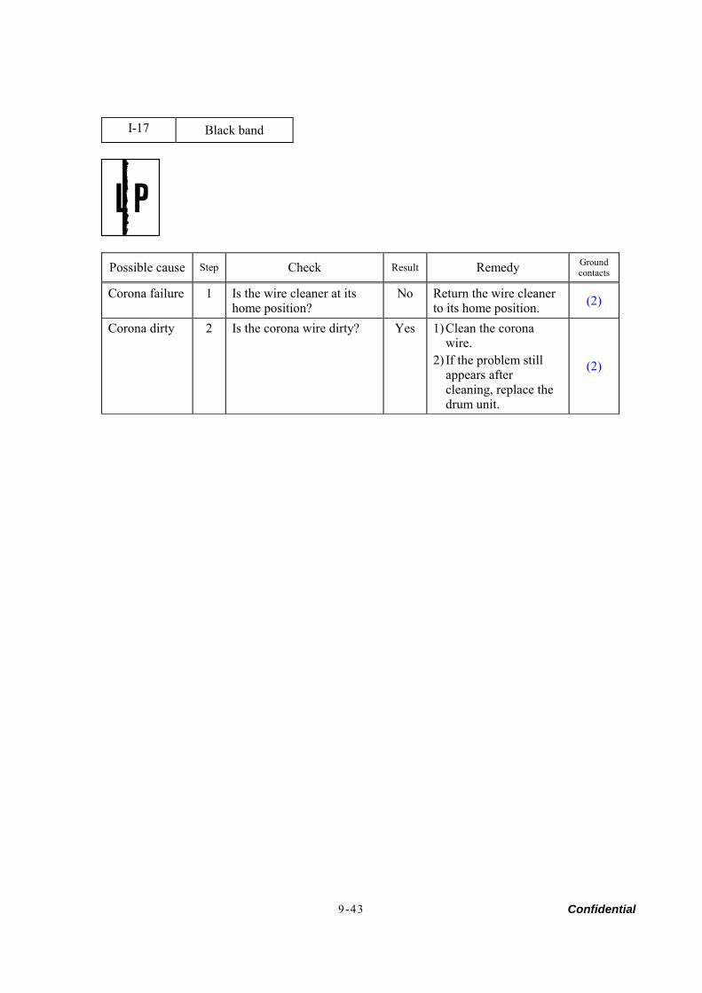
Confidential 9-43
I-17 Black band
Possible cause Step Check Result Remedy Ground contacts
Corona failure 1 Is the wire cleaner at its home position?
No Return the wire cleaner to its home position. (2)
Corona dirty 2 Is the corona wire dirty? Yes 1) Clean the corona wire.
2) If the problem still appears after cleaning, replace the drum unit.
(2)

Confidential 9-44
I-18 Gray background
Possible cause Step Check Result Remedy
No Recommend to use the specified types of paper.
Print paper 1 Does the paper being used meet the paper specification (weight, etc.) Yes Recommend to change to freshly
unpacked paper. Toner sensor failure (printer side)
2 Is the error indication displayed when the toner cartridge and drum unit is taken out of the machine? (The front cover is closed.)
No Toner sensor failure. Clean the toner sensor and check the toner sensor connection.
Toner cartridge failure
3 Is the problem solved after replacing the toner cartridge?
Yes Replace the toner cartridge.
Yes Replace the drum unit. Drum unit failure
4 Is the problem solved after replacing the drum unit? No Replace the high-voltage power
supply PCB.
NOTE: The following cases increase the possibility of this problem. • Acid paper is being used. • The drum unit is at the end of its life. • There is dust or paper powder.
manuals4you.commanuals4you.com
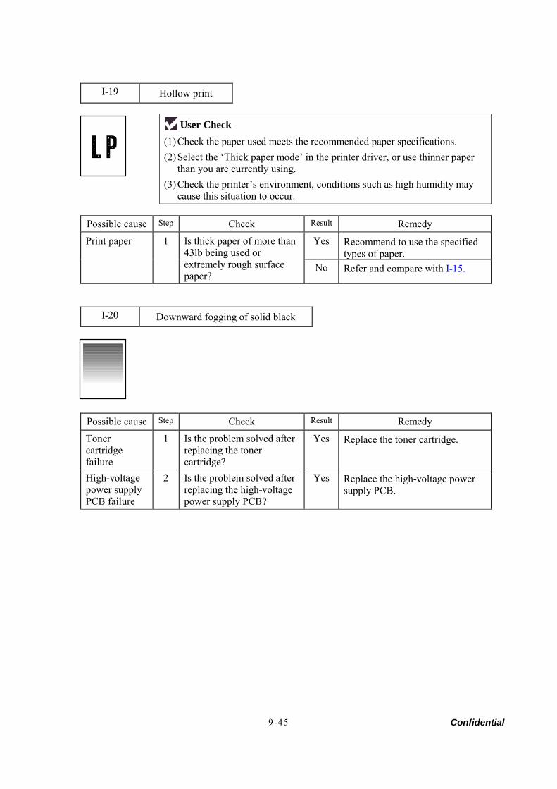
Confidential 9-45
I-19 Hollow print
User Check (1) Check the paper used meets the recommended paper specifications. (2) Select the ‘Thick paper mode’ in the printer driver, or use thinner paper
than you are currently using. (3) Check the printer’s environment, conditions such as high humidity may
cause this situation to occur.
Possible cause Step Check Result Remedy
Yes Recommend to use the specified types of paper.
Print paper 1 Is thick paper of more than 43lb being used or extremely rough surface paper?
No Refer and compare with I-15.
I-20 Downward fogging of solid black
Possible cause Step Check Result Remedy
Toner cartridge failure
1 Is the problem solved after replacing the toner cartridge?
Yes Replace the toner cartridge.
High-voltage power supply PCB failure
2 Is the problem solved after replacing the high-voltage power supply PCB?
Yes Replace the high-voltage power supply PCB.

Confidential 9-46
I-21 Horizontal lines
Possible cause Step Check Result Remedy
Paper tray contacts
1 Are the ground contacts on the right side of the paper tray connecting correctly?
No Clean the contacts.
Drum unit 2 Are the high-voltage power supply and drum unit contacted correctly?
No Clean the contacts.
I-22 Light rain
Possible cause Step Check Result Remedy Ground contacts
Drum unit failure
1 Is the problem solved after replacing the drum unit?
Yes Replace the drum unit.
Drum connection failure
2 Is the contact between the drum unit and printer body connected correctly?
No Clean contact electrode both on the drum unit and in the printer body.
(7)
High-voltage power supply PCB failure
3 Is the problem solved after replacing the high-voltage power supply PCB?
Yes Replace the high-voltage power supply PCB.
manuals4you.commanuals4you.com
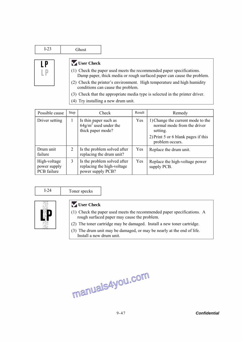
Confidential 9-47
I-23 Ghost
User Check (1) Check the paper used meets the recommended paper specifications.
Damp paper, thick media or rough surfaced paper can cause the problem. (2) Check the printer’s environment. High temperature and high humidity
conditions can cause the problem. (3) Check that the appropriate media type is selected in the printer driver. (4) Try installing a new drum unit.
Possible cause Step Check Result Remedy
Driver setting 1 Is thin paper such as 64g/m2 used under the thick paper mode?
Yes 1) Change the current mode to the normal mode from the driver setting.
2) Print 5 or 6 blank pages if this problem occurs.
Drum unit failure
2 Is the problem solved after replacing the drum unit?
Yes Replace the drum unit.
High-voltage power supply PCB failure
3 Is the problem solved after replacing the high-voltage power supply PCB?
Yes Replace the high-voltage power supply PCB.
I-24 Toner specks
User Check (1) Check the paper used meets the recommended paper specifications. A
rough surfaced paper may cause the problem. (2) The toner cartridge may be damaged. Install a new toner cartridge. (3) The drum unit may be damaged, or may be nearly at the end of life.
Install a new drum unit.
manuals4you.com
manuals4you.com
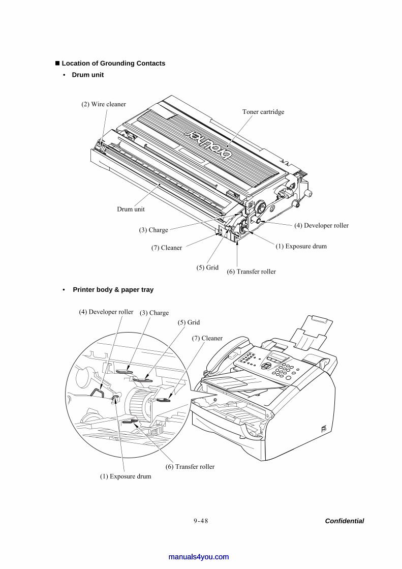
Confidential 9-48
Location of Grounding Contacts • Drum unit
• Printer body & paper tray
(2) Wire cleaner Toner cartridge
(4) Developer roller
(1) Exposure drum
(6) Transfer roller (5) Grid
(7) Cleaner
(3) Charge
Drum unit
(4) Developer roller (3) Charge (5) Grid
(7) Cleaner
(1) Exposure drum
(6) Transfer roller
manuals4you.commanuals4you.com
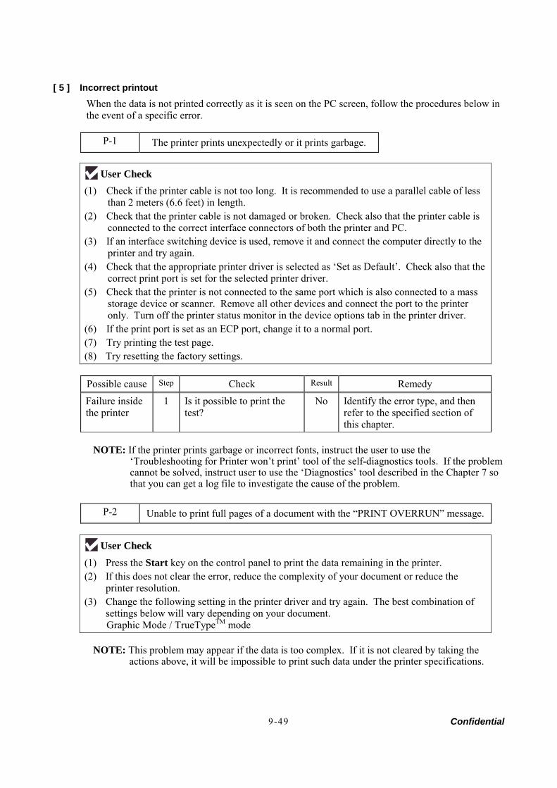
Confidential 9-49
[ 5 ] Incorrect printout When the data is not printed correctly as it is seen on the PC screen, follow the procedures below in the event of a specific error.
P-1 The printer prints unexpectedly or it prints garbage.
User Check (1) Check if the printer cable is not too long. It is recommended to use a parallel cable of less
than 2 meters (6.6 feet) in length. (2) Check that the printer cable is not damaged or broken. Check also that the printer cable is
connected to the correct interface connectors of both the printer and PC. (3) If an interface switching device is used, remove it and connect the computer directly to the
printer and try again. (4) Check that the appropriate printer driver is selected as ‘Set as Default’. Check also that the
correct print port is set for the selected printer driver. (5) Check that the printer is not connected to the same port which is also connected to a mass
storage device or scanner. Remove all other devices and connect the port to the printer only. Turn off the printer status monitor in the device options tab in the printer driver.
(6) If the print port is set as an ECP port, change it to a normal port. (7) Try printing the test page. (8) Try resetting the factory settings.
Possible cause Step Check Result Remedy
Failure inside the printer
1 Is it possible to print the test?
No Identify the error type, and then refer to the specified section of this chapter.
NOTE: If the printer prints garbage or incorrect fonts, instruct the user to use the
‘Troubleshooting for Printer won’t print’ tool of the self-diagnostics tools. If the problem cannot be solved, instruct user to use the ‘Diagnostics’ tool described in the Chapter 7 so that you can get a log file to investigate the cause of the problem.
P-2 Unable to print full pages of a document with the “PRINT OVERRUN” message.
User Check (1) Press the Start key on the control panel to print the data remaining in the printer. (2) If this does not clear the error, reduce the complexity of your document or reduce the
printer resolution. (3) Change the following setting in the printer driver and try again. The best combination of
settings below will vary depending on your document. Graphic Mode / TrueTypeTM mode
NOTE: This problem may appear if the data is too complex. If it is not cleared by taking the
actions above, it will be impossible to print such data under the printer specifications.
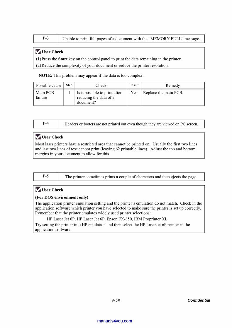
Confidential 9-50
P-3 Unable to print full pages of a document with the “MEMORY FULL” message.
User Check (1) Press the Start key on the control panel to print the data remaining in the printer. (2) Reduce the complexity of your document or reduce the printer resolution.
NOTE: This problem may appear if the data is too complex.
Possible cause Step Check Result Remedy
Main PCB failure
1 Is it possible to print after reducing the data of a document?
Yes Replace the main PCB.
P-4 Headers or footers are not printed out even though they are viewed on PC screen.
User Check Most laser printers have a restricted area that cannot be printed on. Usually the first two lines and last two lines of text cannot print (leaving 62 printable lines). Adjust the top and bottom margins in your document to allow for this.
P-5 The printer sometimes prints a couple of characters and then ejects the page.
User Check (For DOS environment only) The application printer emulation setting and the printer’s emulation do not match. Check in the application software which printer you have selected to make sure the printer is set up correctly. Remember that the printer emulates widely used printer selections:
HP Laser Jet 6P, HP Laser Jet 6P, Epson FX-850, IBM Proprinter XL Try setting the printer into HP emulation and then select the HP LaserJet 6P printer in the application software.
manuals4you.commanuals4you.com
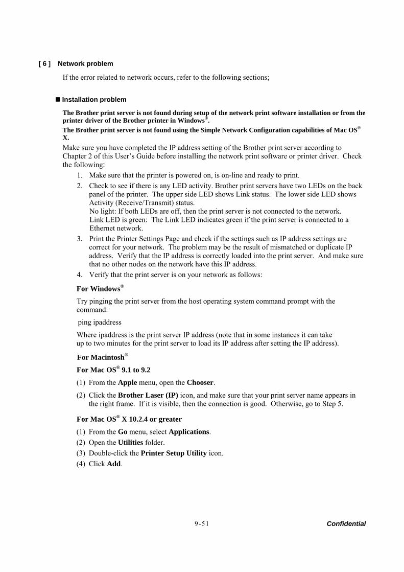
Confidential 9-51
[ 6 ] Network problem
If the error related to network occurs, refer to the following sections;
Installation problem
The Brother print server is not found during setup of the network print software installation or from the printer driver of the Brother printer in Windows®. The Brother print server is not found using the Simple Network Configuration capabilities of Mac OS® X. Make sure you have completed the IP address setting of the Brother print server according to Chapter 2 of this User’s Guide before installing the network print software or printer driver. Check the following:
1. Make sure that the printer is powered on, is on-line and ready to print. 2. Check to see if there is any LED activity. Brother print servers have two LEDs on the back
panel of the printer. The upper side LED shows Link status. The lower side LED shows Activity (Receive/Transmit) status. No light: If both LEDs are off, then the print server is not connected to the network. Link LED is green: The Link LED indicates green if the print server is connected to a Ethernet network.
3. Print the Printer Settings Page and check if the settings such as IP address settings are correct for your network. The problem may be the result of mismatched or duplicate IP address. Verify that the IP address is correctly loaded into the print server. And make sure that no other nodes on the network have this IP address.
4. Verify that the print server is on your network as follows:
For Windows®
Try pinging the print server from the host operating system command prompt with the command:
ping ipaddress
Where ipaddress is the print server IP address (note that in some instances it can take up to two minutes for the print server to load its IP address after setting the IP address).
For Macintosh®
For Mac OS® 9.1 to 9.2
(1) From the Apple menu, open the Chooser.
(2) Click the Brother Laser (IP) icon, and make sure that your print server name appears in the right frame. If it is visible, then the connection is good. Otherwise, go to Step 5.
For Mac OS® X 10.2.4 or greater
(1) From the Go menu, select Applications. (2) Open the Utilities folder. (3) Double-click the Printer Setup Utility icon. (4) Click Add.
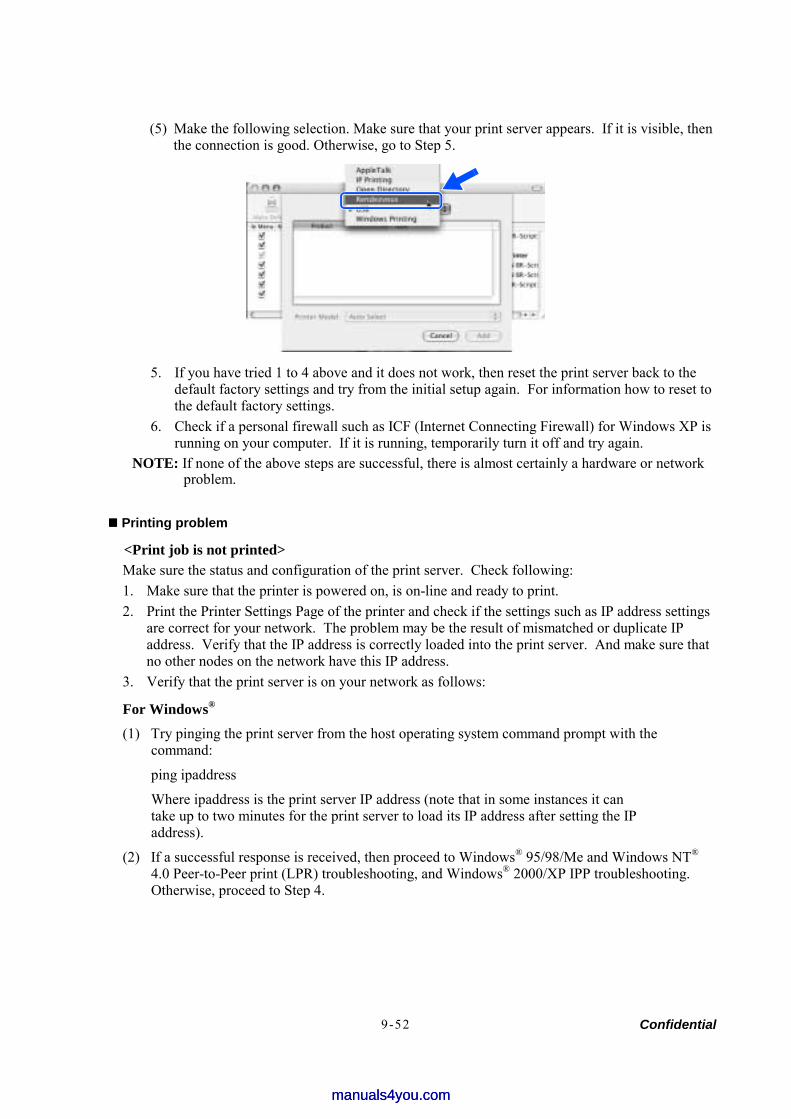
Confidential 9-52
(5) Make the following selection. Make sure that your print server appears. If it is visible, then the connection is good. Otherwise, go to Step 5.
5. If you have tried 1 to 4 above and it does not work, then reset the print server back to the default factory settings and try from the initial setup again. For information how to reset to the default factory settings.
6. Check if a personal firewall such as ICF (Internet Connecting Firewall) for Windows XP is running on your computer. If it is running, temporarily turn it off and try again.
NOTE: If none of the above steps are successful, there is almost certainly a hardware or network problem.
Printing problem
<Print job is not printed> Make sure the status and configuration of the print server. Check following: 1. Make sure that the printer is powered on, is on-line and ready to print. 2. Print the Printer Settings Page of the printer and check if the settings such as IP address settings
are correct for your network. The problem may be the result of mismatched or duplicate IP address. Verify that the IP address is correctly loaded into the print server. And make sure that no other nodes on the network have this IP address.
3. Verify that the print server is on your network as follows:
For Windows®
(1) Try pinging the print server from the host operating system command prompt with the command:
ping ipaddress
Where ipaddress is the print server IP address (note that in some instances it can take up to two minutes for the print server to load its IP address after setting the IP address).
(2) If a successful response is received, then proceed to Windows® 95/98/Me and Windows NT® 4.0 Peer-to-Peer print (LPR) troubleshooting, and Windows® 2000/XP IPP troubleshooting. Otherwise, proceed to Step 4.
manuals4you.commanuals4you.com
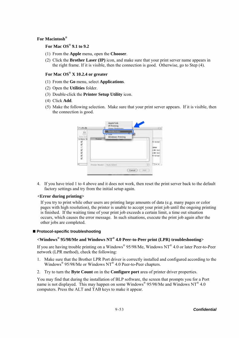
Confidential 9-53
For Macintosh®
For Mac OS® 9.1 to 9.2
(1) From the Apple menu, open the Chooser. (2) Click the Brother Laser (IP) icon, and make sure that your print server name appears in
the right frame. If it is visible, then the connection is good. Otherwise, go to Step (4).
For Mac OS® X 10.2.4 or greater
(1) From the Go menu, select Applications. (2) Open the Utilities folder. (3) Double-click the Printer Setup Utility icon. (4) Click Add. (5) Make the following selection. Make sure that your print server appears. If it is visible, then
the connection is good.
4. If you have tried 1 to 4 above and it does not work, then reset the print server back to the default factory settings and try from the initial setup again.
<Error during printing> If you try to print while other users are printing large amounts of data (e.g. many pages or color pages with high resolution), the printer is unable to accept your print job until the ongoing printing is finished. If the waiting time of your print job exceeds a certain limit, a time out situation occurs, which causes the error message. In such situations, execute the print job again after the other jobs are completed.
Protocol-specific troubleshooting
<Windows® 95/98/Me and Windows NT® 4.0 Peer-to-Peer print (LPR) troubleshooting>
If you are having trouble printing on a Windows® 95/98/Me, Windows NT® 4.0 or later Peer-to-Peer network (LPR method), check the following:
1. Make sure that the Brother LPR Port driver is correctly installed and configured according to the Windows® 95/98/Me or Windows NT® 4.0 Peer-to-Peer chapters.
2. Try to turn the Byte Count on in the Configure port area of printer driver properties.
You may find that during the installation of BLP software, the screen that prompts you for a Port name is not displayed. This may happen on some Windows® 95/98/Me and Windows NT® 4.0 computers. Press the ALT and TAB keys to make it appear.
Confidential 9-54
<Windows® 95/98/Me and Windows NT® 4.0 Peer-to-Peer print (NetBIOS) troubleshooting>
If you are having trouble printing on a Windows® 95/98/Me, Windows NT® 4.0 or later Peer-to-Peer network (NetBIOS), check the following:
1. Make sure that the Brother NetBIOS Port driver is correctly installed and configured according to the Windows® 95/98/Me or Windows NT® 4.0 Peer-to-Peer (NetBIOS) chapters. You may find that during the installation of the port driver, the screen that prompts you for a Port name is not displayed. This happens on some Windows® 95/98/Me and Windows NT® 4.0 computers. Press the ALT and TAB keys to make it appear.
2. Make sure that the print server is configured to be in the same workgroup or domain as the rest of your computers. It may take several minutes for the print server to appear in the network neighborhood.
<Windows® 2000/XP IPP troubleshooting>
Want to use a different Port number other than 631. If you are using Port 631 for IPP printing, you may find that your firewall may not let the print data through. If this is the case, use a different port number (port 80), or configure your Firewall to allow Port 631 data through.
To send a print job using IPP to a printer using Port 80 (the standard HTTP port) enter the following when configuring your Windows® 2000/XP system.
http://ip_address/ipp
Get More Info option in Windows® 2000 not working
If you are using a URL of:
http://ip_address:631 or http://ip_address:631/ipp ,
the Get More Info option in Windows® 2000 will not function. If you wish to use the Get More Info option, use the following URL:
http://ip_address
<Web browser troubleshooting (TCP/IP)>
1. If you can not connect to the print server using your web browser it may be worth checking the Proxy Settings of your browser. Look in the Exceptions setting and if necessary, type in the IP address of the print server. This will stop your PC from trying to connect to your ISP or proxy server every time you wish to look at the printer server.
2. Make sure that you are using the proper web browser, we recommend Netscape Navigator® version 4.0 or later/ Microsoft Internet Explorer® version 5.0 or later.
manuals4you.commanuals4you.com
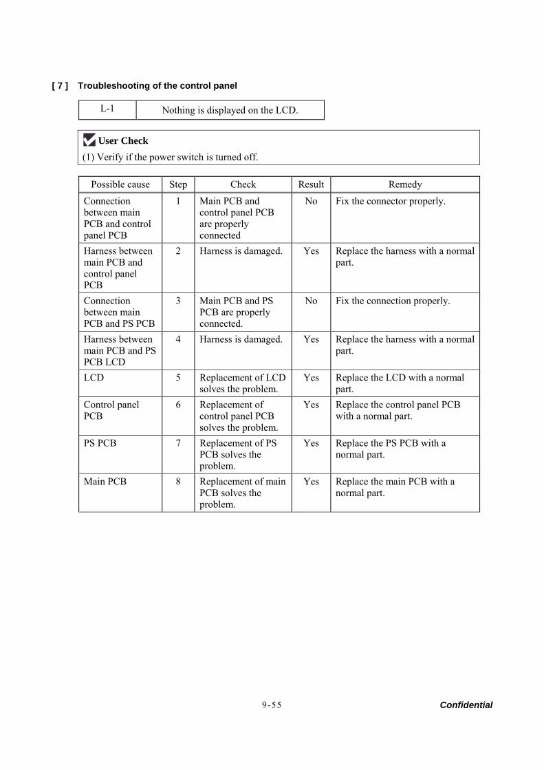
Confidential 9-55
[ 7 ] Troubleshooting of the control panel
L-1 Nothing is displayed on the LCD.
User Check (1) Verify if the power switch is turned off.
Possible cause Step Check Result Remedy
Connection between main PCB and control panel PCB
1 Main PCB and control panel PCB are properly connected
No Fix the connector properly.
Harness between main PCB and control panel PCB
2 Harness is damaged. Yes Replace the harness with a normal part.
Connection between main PCB and PS PCB
3 Main PCB and PS PCB are properly connected.
No Fix the connection properly.
Harness between main PCB and PS PCB LCD
4 Harness is damaged. Yes Replace the harness with a normal part.
LCD 5 Replacement of LCD solves the problem.
Yes Replace the LCD with a normal part.
Control panel PCB
6 Replacement of control panel PCB solves the problem.
Yes Replace the control panel PCB with a normal part.
PS PCB 7 Replacement of PS PCB solves the problem.
Yes Replace the PS PCB with a normal part.
Main PCB 8 Replacement of main PCB solves the problem.
Yes Replace the main PCB with a normal part.
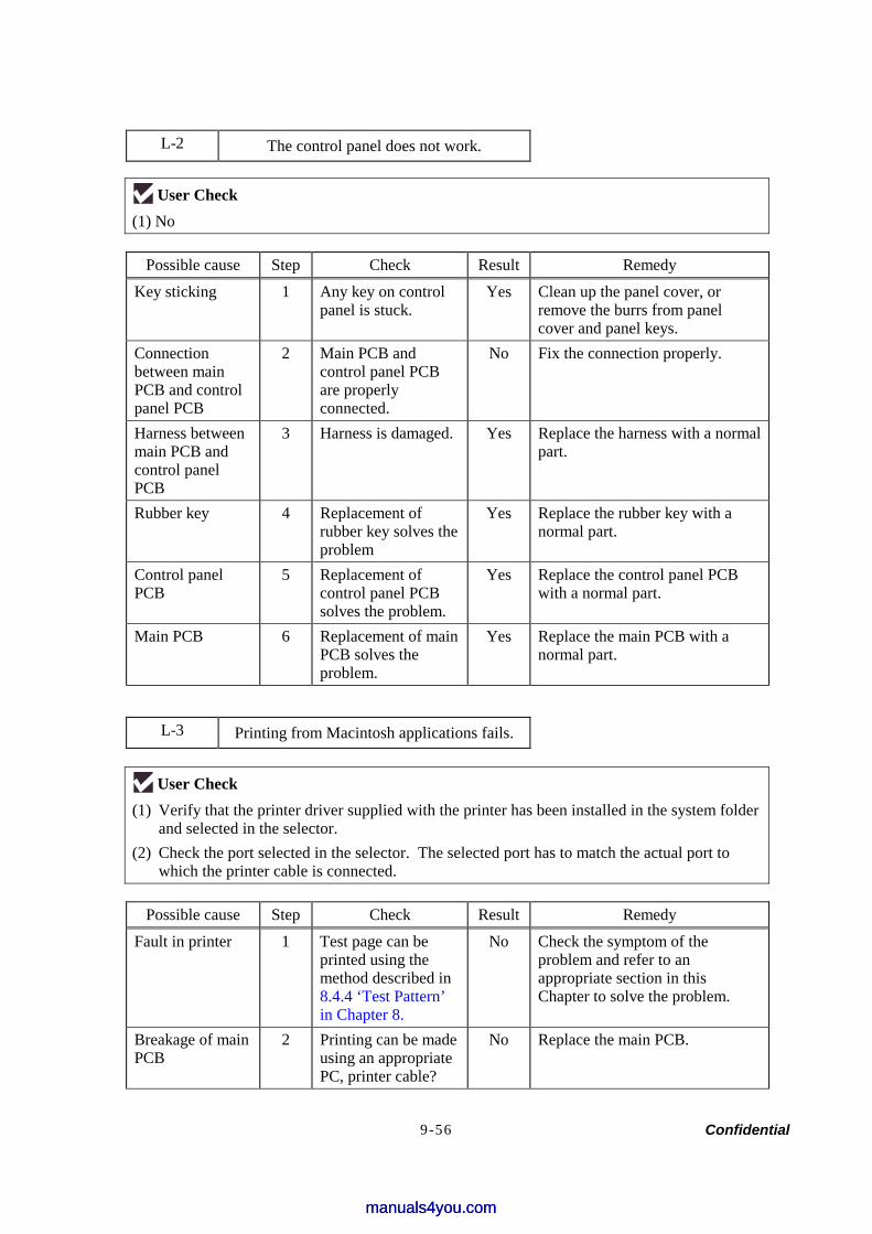
Confidential 9-56
L-2 The control panel does not work.
User Check (1) No
Possible cause Step Check Result Remedy
Key sticking 1 Any key on control panel is stuck.
Yes Clean up the panel cover, or remove the burrs from panel cover and panel keys.
Connection between main PCB and control panel PCB
2 Main PCB and control panel PCB are properly connected.
No Fix the connection properly.
Harness between main PCB and control panel PCB
3 Harness is damaged. Yes Replace the harness with a normal part.
Rubber key 4 Replacement of rubber key solves the problem
Yes Replace the rubber key with a normal part.
Control panel PCB
5 Replacement of control panel PCB solves the problem.
Yes Replace the control panel PCB with a normal part.
Main PCB 6 Replacement of main PCB solves the problem.
Yes Replace the main PCB with a normal part.
L-3 Printing from Macintosh applications fails.
User Check
(1) Verify that the printer driver supplied with the printer has been installed in the system folder and selected in the selector.
(2) Check the port selected in the selector. The selected port has to match the actual port to which the printer cable is connected.
Possible cause Step Check Result Remedy
Fault in printer 1 Test page can be printed using the method described in 8.4.4 ‘Test Pattern’ in Chapter 8.
No Check the symptom of the problem and refer to an appropriate section in this Chapter to solve the problem.
Breakage of main PCB
2 Printing can be made using an appropriate PC, printer cable?
No Replace the main PCB.
manuals4you.commanuals4you.com
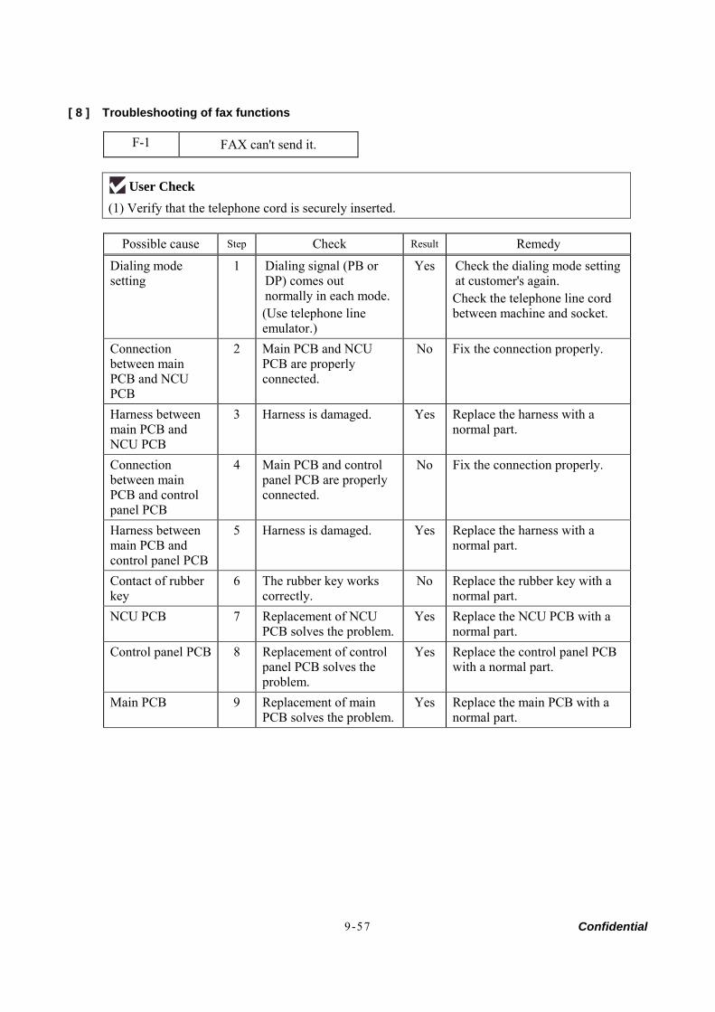
Confidential 9-57
[ 8 ] Troubleshooting of fax functions
F-1 FAX can't send it.
User Check (1) Verify that the telephone cord is securely inserted.
Possible cause Step Check Result Remedy
Dialing mode setting
1 Dialing signal (PB or DP) comes out normally in each mode. (Use telephone line emulator.)
Yes Check the dialing mode setting at customer's again. Check the telephone line cord between machine and socket.
Connection between main PCB and NCU PCB
2 Main PCB and NCU PCB are properly connected.
No Fix the connection properly.
Harness between main PCB and NCU PCB
3 Harness is damaged. Yes Replace the harness with a normal part.
Connection between main PCB and control panel PCB
4 Main PCB and control panel PCB are properly connected.
No Fix the connection properly.
Harness between main PCB and control panel PCB
5 Harness is damaged. Yes Replace the harness with a normal part.
Contact of rubber key
6 The rubber key works correctly.
No Replace the rubber key with a normal part.
NCU PCB 7 Replacement of NCU PCB solves the problem.
Yes Replace the NCU PCB with a normal part.
Control panel PCB 8 Replacement of control panel PCB solves the problem.
Yes Replace the control panel PCB with a normal part.
Main PCB 9 Replacement of main PCB solves the problem.
Yes Replace the main PCB with a normal part.
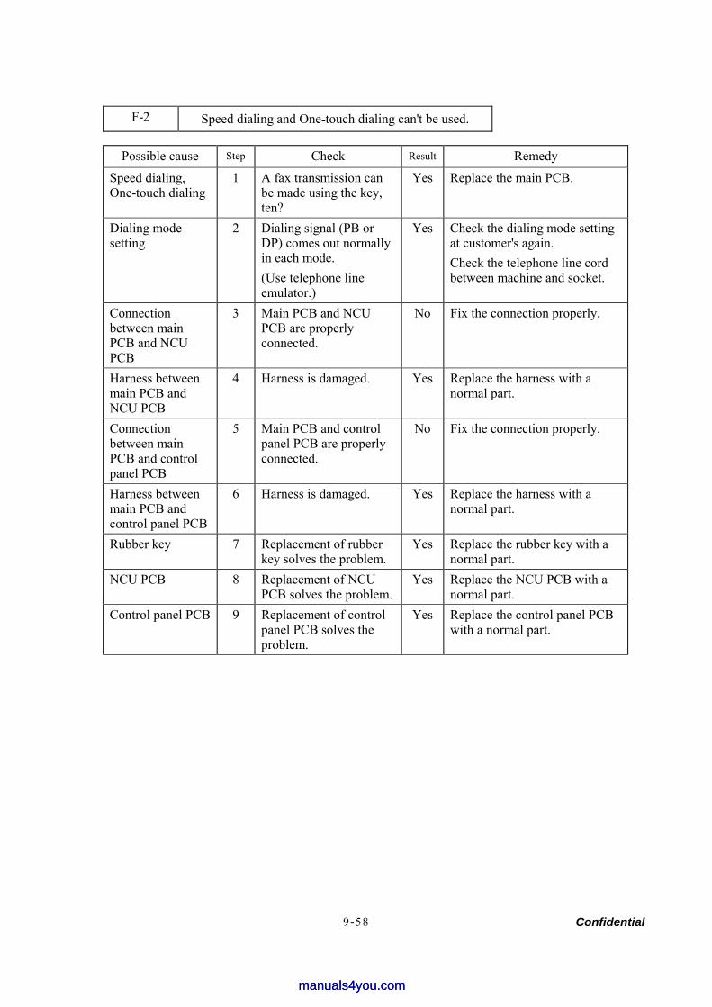
Confidential 9-58
F-2 Speed dialing and One-touch dialing can't be used.
Possible cause Step Check Result Remedy
Speed dialing, One-touch dialing
1 A fax transmission can be made using the key, ten?
Yes Replace the main PCB.
Dialing mode setting
2 Dialing signal (PB or DP) comes out normally in each mode. (Use telephone line emulator.)
Yes Check the dialing mode setting at customer's again. Check the telephone line cord between machine and socket.
Connection between main PCB and NCU PCB
3 Main PCB and NCU PCB are properly connected.
No Fix the connection properly.
Harness between main PCB and NCU PCB
4 Harness is damaged. Yes Replace the harness with a normal part.
Connection between main PCB and control panel PCB
5 Main PCB and control panel PCB are properly connected.
No Fix the connection properly.
Harness between main PCB and control panel PCB
6 Harness is damaged. Yes Replace the harness with a normal part.
Rubber key 7 Replacement of rubber key solves the problem.
Yes Replace the rubber key with a normal part.
NCU PCB 8 Replacement of NCU PCB solves the problem.
Yes Replace the NCU PCB with a normal part.
Control panel PCB 9 Replacement of control panel PCB solves the problem.
Yes Replace the control panel PCB with a normal part.
manuals4you.commanuals4you.com
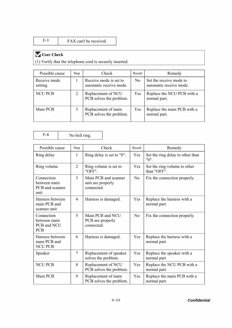
Confidential 9-59
F-3 FAX can't be received.
User Check (1) Verify that the telephone cord is securely inserted.
Possible cause Step Check Result Remedy
Receive mode setting
1 Receive mode is set to automatic receive mode.
No Set the receive mode to automatic receive mode.
NCU PCB 2 Replacement of NCU PCB solves the problem.
Yes Replace the NCU PCB with a normal part.
Main PCB 3 Replacement of main PCB solves the problem.
Yes Replace the main PCB with a normal part.
F-4 No bell ring.
Possible cause Step Check Result Remedy
Ring delay 1 Ring delay is set to "0". Yes Set the ring delay to other than "0".
Ring volume 2 Ring volume is set to "OFF".
Yes Set the ring volume to other than "OFF".
Connection between main PCB and scanner unit
3 Main PCB and scanner unit are properly connected.
No Fix the connection properly.
Harness between main PCB and scanner unit
4 Harness is damaged. Yes Replace the harness with a normal part.
Connection between main PCB and NCU PCB
5 Main PCB and NCU PCB are properly connected.
No Fix the connection properly.
Harness between main PCB and NCU PCB
6 Harness is damaged. Yes Replace the harness with a normal part.
Speaker 7 Replacement of speaker solves the problem.
Yes Replace the speaker with a normal part.
NCU PCB 8 Replacement of NCU PCB solves the problem.
Yes Replace the NCU PCB with a normal part.
Main PCB 9 Replacement of main PCB solves the problem.
Yes Replace the main PCB with a normal part.
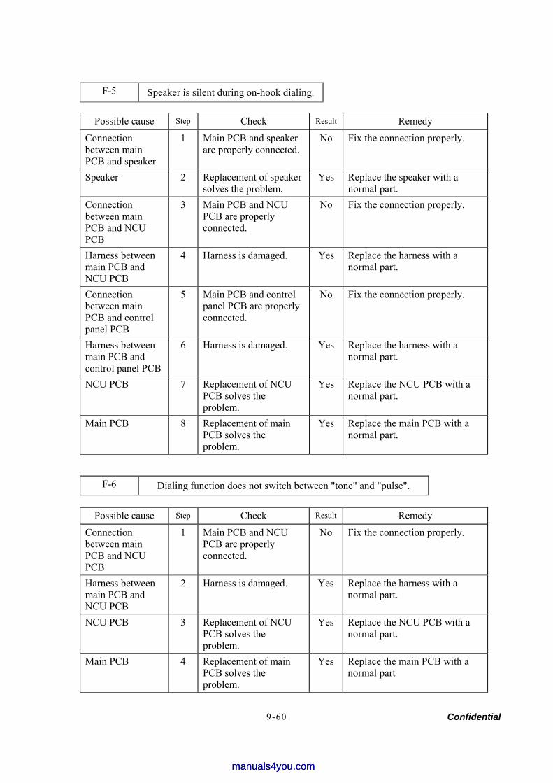
Confidential 9-60
F-5 Speaker is silent during on-hook dialing.
Possible cause Step Check Result Remedy
Connection between main PCB and speaker
1 Main PCB and speaker are properly connected.
No Fix the connection properly.
Speaker 2 Replacement of speaker solves the problem.
Yes Replace the speaker with a normal part.
Connection between main PCB and NCU PCB
3 Main PCB and NCU PCB are properly connected.
No Fix the connection properly.
Harness between main PCB and NCU PCB
4 Harness is damaged. Yes Replace the harness with a normal part.
Connection between main PCB and control panel PCB
5 Main PCB and control panel PCB are properly connected.
No Fix the connection properly.
Harness between main PCB and control panel PCB
6 Harness is damaged. Yes Replace the harness with a normal part.
NCU PCB 7 Replacement of NCU PCB solves the problem.
Yes Replace the NCU PCB with a normal part.
Main PCB 8 Replacement of main PCB solves the problem.
Yes Replace the main PCB with a normal part.
F-6 Dialing function does not switch between "tone" and "pulse".
Possible cause Step Check Result Remedy
Connection between main PCB and NCU PCB
1 Main PCB and NCU PCB are properly connected.
No Fix the connection properly.
Harness between main PCB and NCU PCB
2 Harness is damaged. Yes Replace the harness with a normal part.
NCU PCB 3 Replacement of NCU PCB solves the problem.
Yes Replace the NCU PCB with a normal part.
Main PCB 4 Replacement of main PCB solves the problem.
Yes Replace the main PCB with a normal part
manuals4you.commanuals4you.com

Confidential
FAX2820/2920 MFC7220/7225N
APPENDIX 1. SERIAL NUMBERING SYSTEM
This appendix shows the location of serial number labels put on some parts and lists the coding information pertaining to the serial numbers.
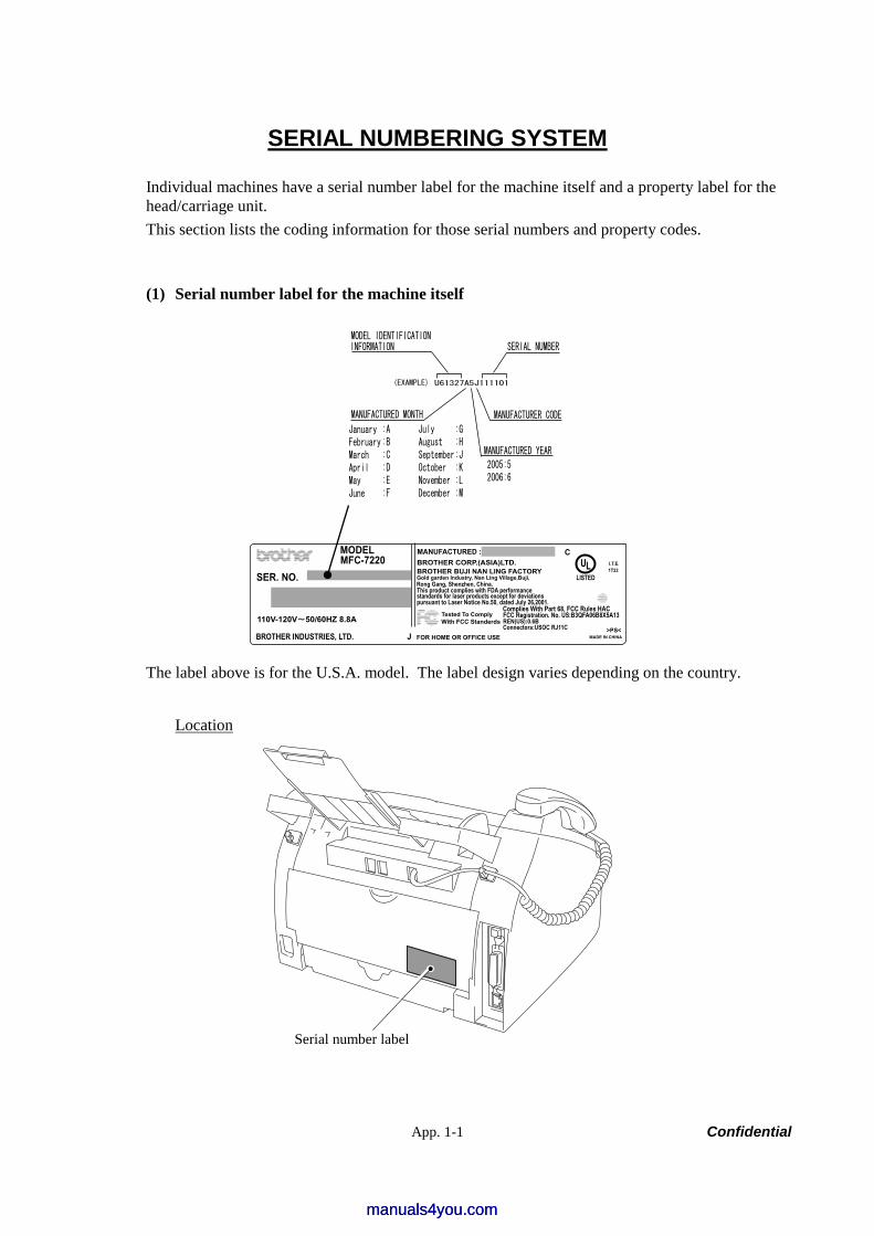
App. 1-1 Confidential
SERIAL NUMBERING SYSTEM
Individual machines have a serial number label for the machine itself and a property label for the head/carriage unit. This section lists the coding information for those serial numbers and property codes.
(1) Serial number label for the machine itself
MADE IN CHINA
>PS<FOR HOME OR OFFICE USE
With FCC StanderdsTested To Comply
Connectors:USOC RJ11CREN(US):0.6BFCC Registration. No. US:B3QFA06B8X5A13Complies With Part 68, FCC Rules HAC
pursuant to Laser Notice No.50, dated July 26,2001.standards for laser products except for deviationsThis product complies with FDA performanceRong Gang, Shenzhen, China.Gold garden Industry, Nan Ling Village,Buji,BROTHER BUJI NAN LING FACTORYBROTHER CORP.(ASIA)LTD.
MANUFACTURED :
ULLISTED
CI.T.E.1T22
MODELMFC-7220
SER. NO.
110V-120V 50/60HZ 8.8A
BROTHER INDUSTRIES, LTD. J
The label above is for the U.S.A. model. The label design varies depending on the country.
Location
Serial number label
manuals4you.commanuals4you.com

App. 1-2 Confidential
(2) Laser unit serial label
REGARDING X delay and Y delay It indicates required delay amount for writing in each of main (X) and sub (Y) scanning direction
Location
LSU MODEL DISTINCTION
FRAME MANUFACTURER AND MOLD DISTINCTION T1 THE 1st. MOLD Y3 THE 3rd. MOLD
POLYGON MOTOR DISTINCTION
INSPECTION MACHINE
SERIAL NUMBER
Y delay
X delay
Laser unit serial label
Confidential
FAX2820/2920 MFC7220/7225N
APPENDIX 2. FIRMWARE INSTALLATION
This appendix provides instructions on how to update firmware stored in the flash ROM on the main PCB or load firmware to a new main PCB from the host PC. No hardware replacement is required for updating.
A2.1 INSTALLING THE UPDATE DATA TO THE MACHINE ........................................App. 2-1
A2.2 SETTING ID CODES TO MACHINES ....................................................................App. 2-8
manuals4you.commanuals4you.com
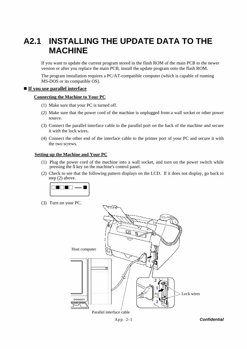
App. 2-1 Confidential
A2.1 INSTALLING THE UPDATE DATA TO THE MACHINE
If you want to update the current program stored in the flash ROM of the main PCB to the newer version or after you replace the main PCB, install the update program onto the flash ROM. The program installation requires a PC/AT-compatible computer (which is capable of running MS-DOS or its compatible OS).
If you use parallel interface Connecting the Machine to Your PC
(1) Make sure that your PC is turned off. (2) Make sure that the power cord of the machine is unplugged from a wall socket or other power
source. (3) Connect the parallel interface cable to the parallel port on the back of the machine and secure
it with the lock wires. (4) Connect the other end of the interface cable to the printer port of your PC and secure it with
the two screws.
Setting up the Machine and Your PC
(1) Plug the power cord of the machine into a wall socket, and turn on the power switch while pressing the 5 key on the machine's control panel.
(2) Check to see that the following pattern displays on the LCD. If it does not display, go back to step (2) above.
(3) Turn on your PC.
Lock wires
Parallel interface cable
Host computer
1
2
2
App. 2-2 Confidential
Installing the Update Data onto the Flash ROM of the Machine
On a PC running Windows 95
(1) Copy the update data and transfer utility onto the desired same directory of the hard disk. e.g., C:\UPDATE
(2) Click the Start button, point to Programs, and then click MS-DOS Prompt to open an MS-DOS window.
(3) Type the drive letter where the update data and transfer utility are located. In the above example, type C:\ from the command line and press the Enter key. Then type CD UPDATE and press the Enter key.
(4) To start the transfer utility transmitting the update data to the flash ROM of the machine, type the following: ICEN filename /b Where filename is an update data file, e.g., 7225xxxx.dat. Then press the Enter key. During downloading, the machine beeps intermittently. Upon completion of the downloading, the machine beeps continuously. NOTE: If the machine cannot return to the standby state after completion of downloading,
turn the power off and on.
On a PC running Windows 98/Me/2000
(1) Install the printer driver for the parallel port to your PC. (Once installed, no more printer driver is required for your PC.)
(2) Copy the update data onto the desired directory of the hard disk. e.g., C:\UPDATE
(3) Copy the transfer utility “Filedg32.exe” onto the desired directory of the hard disk. (4) Run “Filedg32.exe”.
The Filedrgs window will appear as shown below. (e.g., MFC-7225N)
(5) Drag and drop the update data onto the icon of the model being used in the Filedrgs windows. During downloading, the machine beeps intermittently. Upon completion of the downloading, the machine beeps continuously. NOTE: If the machine cannot return to the standby state after completion of downloading,
turn the power off and on.
manuals4you.commanuals4you.com
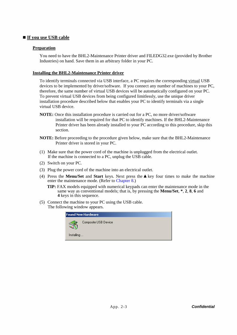
App. 2-3 Confidential
If you use USB cable
Preparation
You need to have the BHL2-Maintenance Printer driver and FILEDG32.exe (provided by Brother Industries) on hand. Save them in an arbitrary folder in your PC.
Installing the BHL2-Maintenance Printer driver
To identify terminals connected via USB interface, a PC requires the corresponding virtual USB devices to be implemented by driver/software. If you connect any number of machines to your PC, therefore, the same number of virtual USB devices will be automatically configured on your PC. To prevent virtual USB devices from being configured limitlessly, use the unique driver installation procedure described below that enables your PC to identify terminals via a single virtual USB device.
NOTE: Once this installation procedure is carried out for a PC, no more driver/software installation will be required for that PC to identify machines. If the BHL2-Maintenance Printer driver has been already installed to your PC according to this procedure, skip this section.
NOTE: Before proceeding to the procedure given below, make sure that the BHL2-Maintenance Printer driver is stored in your PC.
(1) Make sure that the power cord of the machine is unplugged from the electrical outlet. If the machine is connected to a PC, unplug the USB cable.
(2) Switch on your PC. (3) Plug the power cord of the machine into an electrical outlet. (4) Press the Menu/Set and Start keys. Next press the key four times to make the machine
enter the maintenance mode. (Refer to Chapter 8.) TIP: FAX models equipped with numerical keypads can enter the maintenance mode in the
same way as conventional models; that is, by pressing the Menu/Set, *, 2, 8, 6 and 4 keys in this sequence.
(5) Connect the machine to your PC using the USB cable. The following window appears.
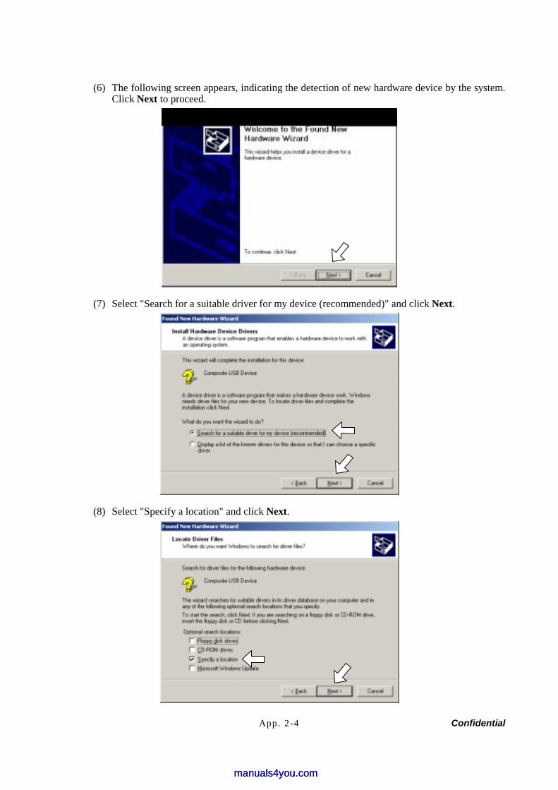
App. 2-4 Confidential
(6) The following screen appears, indicating the detection of new hardware device by the system. Click Next to proceed.
(7) Select "Search for a suitable driver for my device (recommended)" and click Next.
(8) Select "Specify a location" and click Next.
manuals4you.commanuals4you.com

App. 2-5 Confidential
(9) Select the folder where the copy of the BHL2-Maintenance Printer driver is located (or click Browse to specify it), then click OK. (This sample screen is captured on the Windows 2000 desktop.)
(10) Click Next.
(11) To proceed, click Yes.
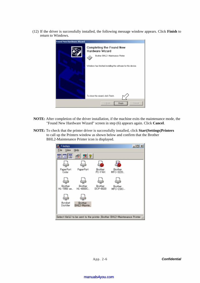
App. 2-6 Confidential
(12) If the driver is successfully installed, the following message window appears. Click Finish to return to Windows.
NOTE: After completion of the driver installation, if the machine exits the maintenance mode, the "Found New Hardware Wizard" screen in step (6) appears again. Click Cancel.
NOTE: To check that the printer driver is successfully installed, click Start|Settings|Printers to call up the Printers window as shown below and confirm that the Brother BHL2-Maintenance Printer icon is displayed.
manuals4you.commanuals4you.com
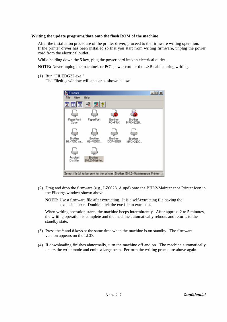
App. 2-7 Confidential
Writing the update programs/data onto the flash ROM of the machine
After the installation procedure of the printer driver, proceed to the firmware writing operation. If the printer driver has been installed so that you start from writing firmware, unplug the power cord from the electrical outlet. While holding down the 5 key, plug the power cord into an electrical outlet. NOTE: Never unplug the machine's or PC's power cord or the USB cable during writing.
(1) Run "FILEDG32.exe." The Filedrgs window will appear as shown below.
(2) Drag and drop the firmware (e.g., LZ0023_A.upd) onto the BHL2-Maintenance Printer icon in the Filedrgs window shown above.
NOTE: Use a firmware file after extracting. It is a self-extracting file having the extension .exe. Double-click the exe file to extract it.
When writing operation starts, the machine beeps intermittently. After approx. 2 to 5 minutes, the writing operation is complete and the machine automatically reboots and returns to the standby state.
(3) Press the * and # keys at the same time when the machine is on standby. The firmware version appears on the LCD.
(4) If downloading finishes abnormally, turn the machine off and on. The machine automatically enters the write mode and emits a large beep. Perform the writing procedure above again.
App. 2-8 Confidential
A2.2 SETTING ID CODES TO MACHINES Brother driver machines are assigned unique ID codes (character strings) at the factory. If you replace the main PCB of the machine, the machine will lose its assigned ID code so that it will not be identified by the connected PC*. You need to assign a unique ID code (character string) to the machine according to the procedure given here. For models covered by this manual, set serial numbers given to individual machines as ID codes. (* ID codes are essential when more than one machine is connected to a single PC via USB.) Please check the printer driver of FAX-2820, FAX-2920, MFC-7220 or MFC-7225N is installed in a host computer before working. When not installed. Please install a printer driver in a host computer before working. (1) Double-click the brmainte.EXE file (maintenance utility). (2) Select Input Information from Menu. Select the applicable model name. (3) Check the port (USB) which the printer is connected through and click “Serial No.” in the
lower box. Enter the serial number (the last nine digits) of the printer into the box at the right hand side and click the OK button. The serial number is shown in the window, and check that it is correct. The setting of the serial number is completed.
manuals4you.commanuals4you.com

Confidential
FAX2820/2920 MFC7220/7225N
APPENDIX 3. CUSTOMIZING CODES ACCORDING TO SHIPPING DESTINATION
This appendix provides instructions on how to set up the customizing codes for the various preferences exclusively designed for each destination (e.g. language). Those codes are stored in the memory (EEPROM) mounted on the main PCB. If the main PCB is replaced, therefore, you need to set the proper customizing code with the machine in the maintenance mode. NOTE: Customizing codes customize firmware for individual models, enabling the common
firmware to be used for various models. They come with the firmware data provided by Brother Industries.

App. 3-1 Confidential
EEPROM CUSTOMIZING CODES
This function allows you to customize the EEPROM according to language, function settings, and firmware switch settings.
Operating Procedure (1) Press the Menu/Set and Start keys. Next press the key four times to make the machine
enter the maintenance mode. TIP: FAX models equipped with numerical keypads can enter the maintenance mode in the
same way as conventional models; that is, by pressing the Menu/Set, *, 2, 8, 6 and 4 keys in this sequence.
The machine beeps for approx. one second and displays " " on the LCD.
(2) Press the 7 and 4 keys in this order in the initial stage of the maintenance mode. The current customizing code appears (e.g., 8001 in the case of FAX-2820 U.S.A. model).
(3) Enter the desired customizing code (e.g., 0002 in the case of FAX-2820 CANADA model). The newly entered code appears.
NOTE: If a wrong 4-digit code is entered, the machine will malfunction.
(4) Press the Start key. The machine saves the setting and returns to the initial stage of the maintenance mode. If you press the Stop/Exit key or no keys are pressed for one minute in the above procedure, the machine stops the procedure and returns to the initial stage of the maintenance mode.
manuals4you.commanuals4you.com

Confidential
FAX2820/2920 MFC7220/7225N
APPENDIX 4. FIRMWARE SWITCHES (WSW)
This appendix describes the functions of the firmware switches, which can be divided into two groups: one is for customizing preferences designed for the shipping destination (as described in Appendix 3) and the other is for modifying preferences that match the machine to the environmental conditions. Use the latter group if the machine malfunctions due to mismatching.

App. 4-1 Confidential
WSW No. Function Refer to: WSW01 Dial pulse setting App. 4-3 WSW02 Tone signal setting App. 4-4 WSW03 PABX mode setting App. 4-5 WSW04 TRANSFER facility setting App. 4-6 WSW05 1st dial tone and busy tone detection App. 4-7 WSW06 Redial/Pause key setting and 2nd dial tone detection App. 4-9 WSW07 Dial tone setting 1 App. 4-11 WSW08 Dial tone setting 2 App. 4-12 WSW09 Protocol definition 1 App. 4-13 WSW10 Protocol definition 2 App. 4-14 WSW11 Busy tone setting App. 4-15 WSW12 Signal detection condition setting App. 4-16 WSW13 Modem setting App. 4-17 WSW14 AUTO ANS facility setting App. 4-18 WSW15 REDIAL facility setting App. 4-19 WSW16 Function setting 1 App. 4-20 WSW17 Function setting 2 App. 4-21 WSW18 Function setting 3 App. 4-22 WSW19 Transmission speed setting App. 4-23 WSW20 Overseas communications mode setting App. 4-24 WSW21 TAD setting 1 App. 4-25 WSW22 ECM and call waiting caller ID App. 4-26 WSW23 Communications setting App. 4-27 WSW24 TAD setting 2 App. 4-28 WSW25 TAD setting 3 App. 4-29 WSW26 Function setting 4 App. 4-30 WSW27 Function setting 5 App. 4-31 WSW28 Function setting 6 App. 4-32 WSW29 Function setting 7 App. 4-33 WSW30 Function setting 8 App. 4-34 WSW31 Function setting 9 App. 4-35 WSW32 Function setting 10 App. 4-36 WSW33 Function setting 11 App. 4-37 WSW34 Function setting 12 App. 4-38 WSW35 Function setting 13 App. 4-39 WSW36 Function setting 14 App. 4-40 WSW37 Function setting 15 App. 4-41
manuals4you.commanuals4you.com
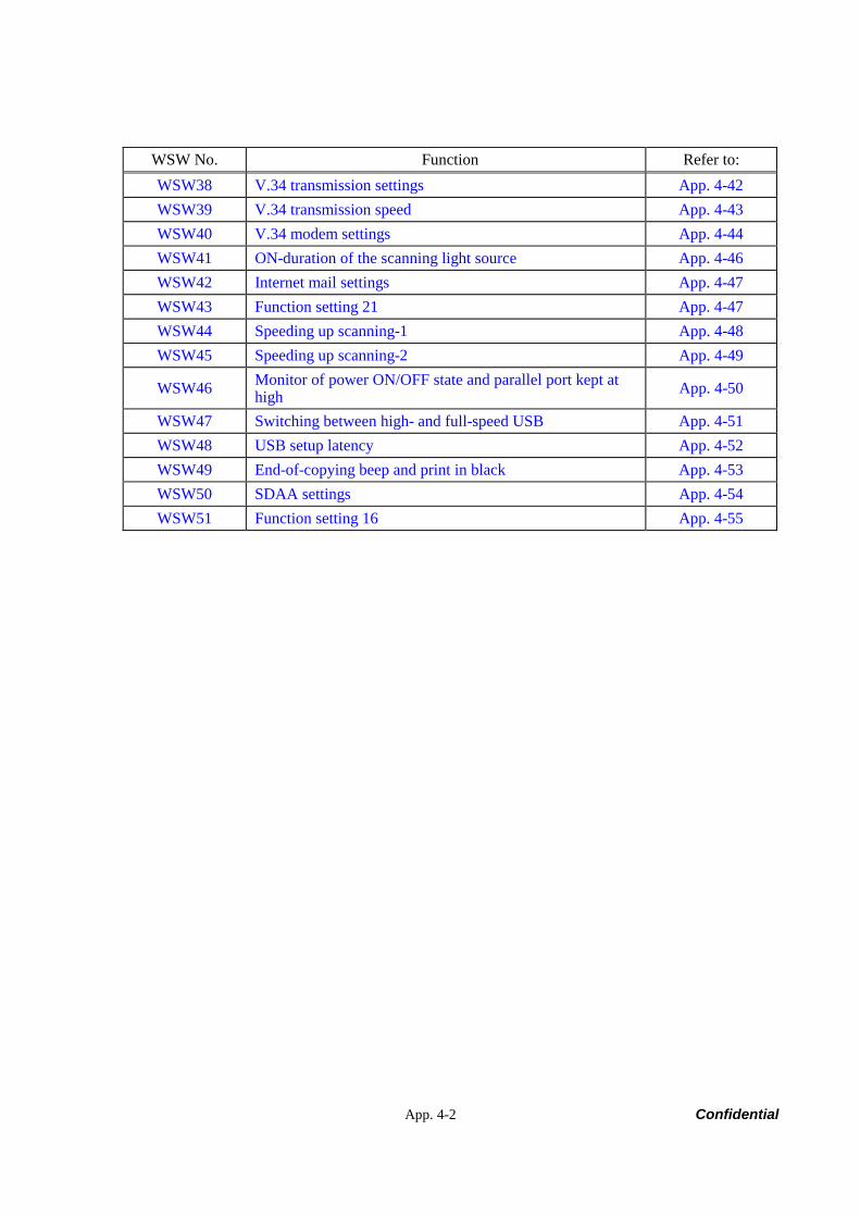
App. 4-2 Confidential
WSW No. Function Refer to: WSW38 V.34 transmission settings App. 4-42 WSW39 V.34 transmission speed App. 4-43 WSW40 V.34 modem settings App. 4-44 WSW41 ON-duration of the scanning light source App. 4-46 WSW42 Internet mail settings App. 4-47 WSW43 Function setting 21 App. 4-47 WSW44 Speeding up scanning-1 App. 4-48 WSW45 Speeding up scanning-2 App. 4-49
WSW46 Monitor of power ON/OFF state and parallel port kept at high App. 4-50
WSW47 Switching between high- and full-speed USB App. 4-51 WSW48 USB setup latency App. 4-52 WSW49 End-of-copying beep and print in black App. 4-53 WSW50 SDAA settings App. 4-54 WSW51 Function setting 16 App. 4-55
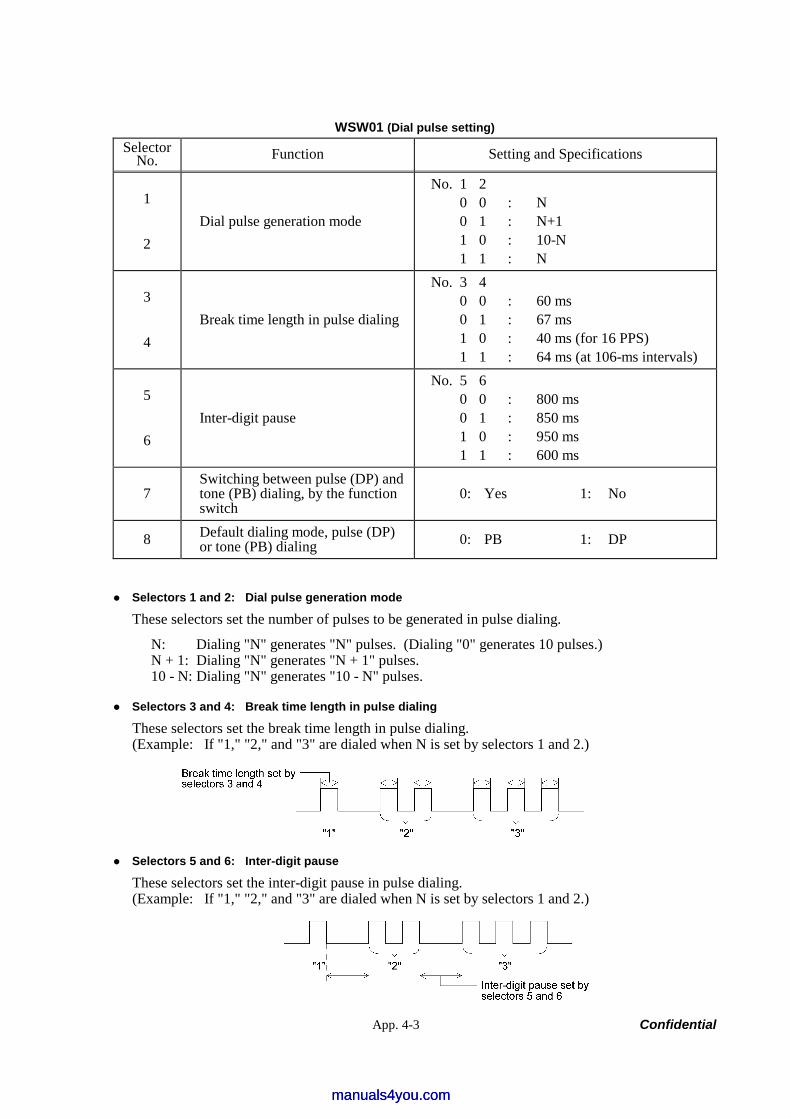
App. 4-3 Confidential
WSW01 (Dial pulse setting) Selector
No. Function Setting and Specifications
1
2 Dial pulse generation mode
No. 1 2 0 0 : N 0 1 : N+1 1 0 : 10-N 1 1 : N
3
4 Break time length in pulse dialing
No. 3 4 0 0 : 60 ms 0 1 : 67 ms 1 0 : 40 ms (for 16 PPS) 1 1 : 64 ms (at 106-ms intervals)
5
6 Inter-digit pause
No. 5 6 0 0 : 800 ms 0 1 : 850 ms 1 0 : 950 ms 1 1 : 600 ms
7 Switching between pulse (DP) and tone (PB) dialing, by the function switch
0: Yes 1: No
8 Default dialing mode, pulse (DP) or tone (PB) dialing 0: PB 1: DP
Selectors 1 and 2: Dial pulse generation mode
These selectors set the number of pulses to be generated in pulse dialing.
N: Dialing "N" generates "N" pulses. (Dialing "0" generates 10 pulses.) N + 1: Dialing "N" generates "N + 1" pulses. 10 - N: Dialing "N" generates "10 - N" pulses.
Selectors 3 and 4: Break time length in pulse dialing
These selectors set the break time length in pulse dialing. (Example: If "1," "2," and "3" are dialed when N is set by selectors 1 and 2.)
Selectors 5 and 6: Inter-digit pause
These selectors set the inter-digit pause in pulse dialing. (Example: If "1," "2," and "3" are dialed when N is set by selectors 1 and 2.)
manuals4you.commanuals4you.com
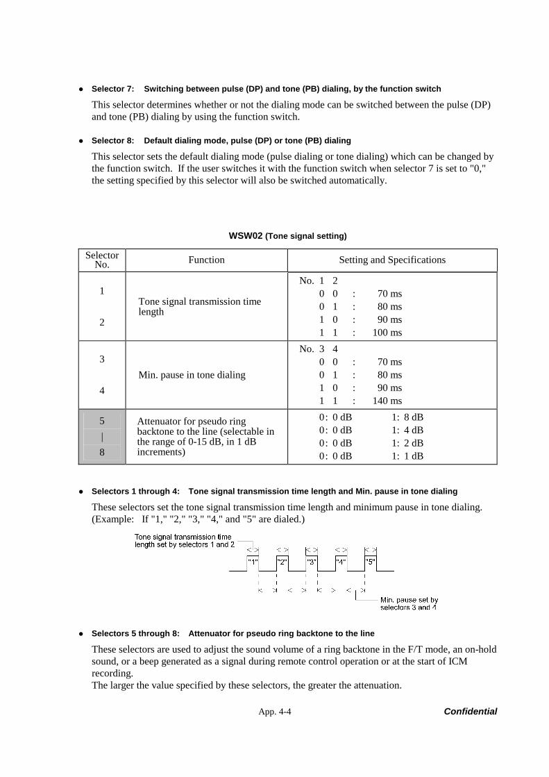
App. 4-4 Confidential
Selector 7: Switching between pulse (DP) and tone (PB) dialing, by the function switch
This selector determines whether or not the dialing mode can be switched between the pulse (DP) and tone (PB) dialing by using the function switch.
Selector 8: Default dialing mode, pulse (DP) or tone (PB) dialing
This selector sets the default dialing mode (pulse dialing or tone dialing) which can be changed by the function switch. If the user switches it with the function switch when selector 7 is set to "0," the setting specified by this selector will also be switched automatically.
WSW02 (Tone signal setting)
Selector No. Function Setting and Specifications
1
2
Tone signal transmission time length
No. 1 2 0 0 : 70 ms 0 1 : 80 ms 1 0 : 90 ms 1 1 : 100 ms
3
4 Min. pause in tone dialing
No. 3 4 0 0 : 70 ms 0 1 : 80 ms 1 0 : 90 ms 1 1 : 140 ms
5 | 8
Attenuator for pseudo ring backtone to the line (selectable in the range of 0-15 dB, in 1 dB increments)
0 : 0 dB 1: 8 dB 0 : 0 dB 1: 4 dB 0 : 0 dB 1: 2 dB 0 : 0 dB 1: 1 dB
Selectors 1 through 4: Tone signal transmission time length and Min. pause in tone dialing
These selectors set the tone signal transmission time length and minimum pause in tone dialing. (Example: If "1," "2," "3," "4," and "5" are dialed.)
Selectors 5 through 8: Attenuator for pseudo ring backtone to the line
These selectors are used to adjust the sound volume of a ring backtone in the F/T mode, an on-hold sound, or a beep generated as a signal during remote control operation or at the start of ICM recording. The larger the value specified by these selectors, the greater the attenuation.
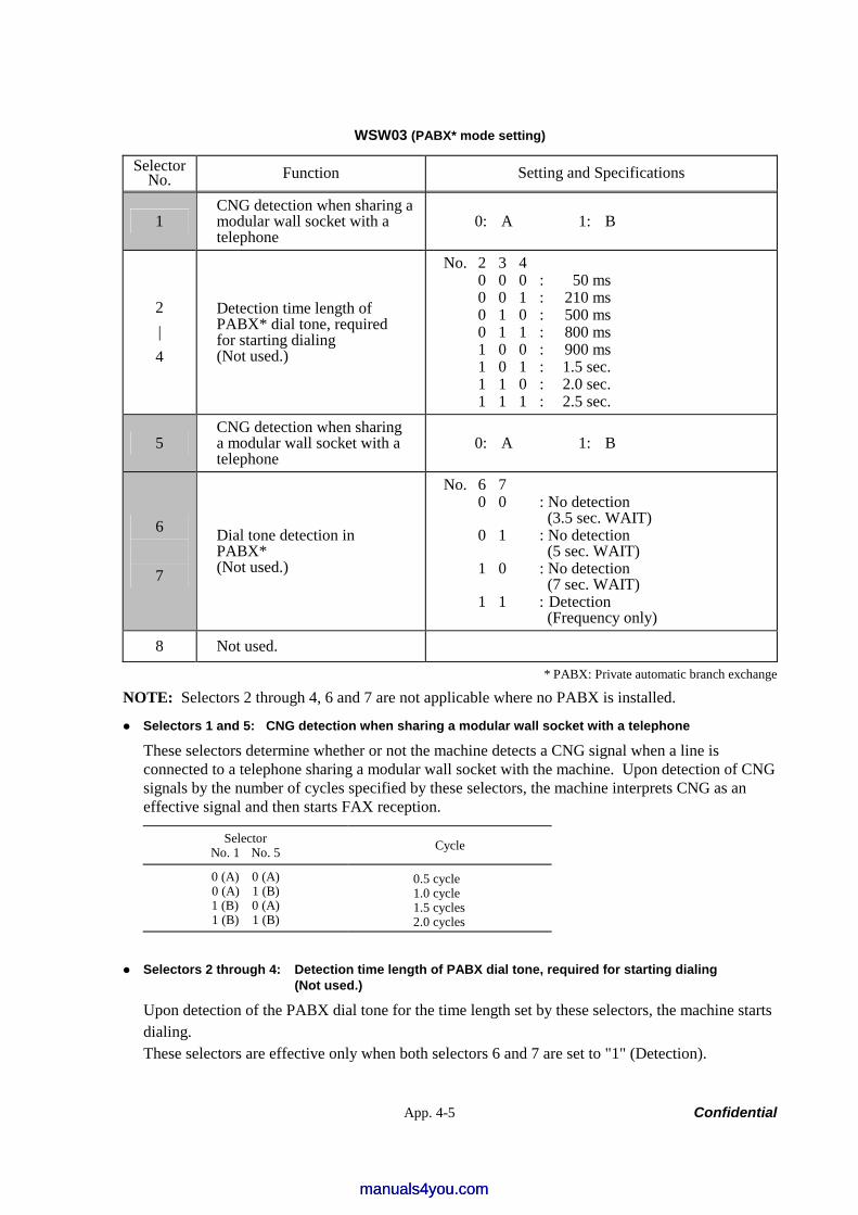
App. 4-5 Confidential
WSW03 (PABX* mode setting)
Selector No. Function Setting and Specifications
1 CNG detection when sharing a modular wall socket with a telephone
0: A 1: B
2 | 4
Detection time length of PABX* dial tone, required for starting dialing (Not used.)
No. 2 3 4 0 0 0 : 50 ms 0 0 1 : 210 ms 0 1 0 : 500 ms 0 1 1 : 800 ms 1 0 0 : 900 ms 1 0 1 : 1.5 sec. 1 1 0 : 2.0 sec. 1 1 1 : 2.5 sec.
5 CNG detection when sharing a modular wall socket with a telephone
0: A 1: B
6
7
Dial tone detection in PABX* (Not used.)
No. 6 7 0 0 : No detection
(3.5 sec. WAIT) 0 1 : No detection
(5 sec. WAIT) 1 0 : No detection
(7 sec. WAIT) 1 1 : Detection
(Frequency only)
8 Not used.
* PABX: Private automatic branch exchange
NOTE: Selectors 2 through 4, 6 and 7 are not applicable where no PABX is installed.
Selectors 1 and 5: CNG detection when sharing a modular wall socket with a telephone
These selectors determine whether or not the machine detects a CNG signal when a line is connected to a telephone sharing a modular wall socket with the machine. Upon detection of CNG signals by the number of cycles specified by these selectors, the machine interprets CNG as an effective signal and then starts FAX reception.
Selector No. 1 No. 5 Cycle
0 (A) 0 (A) 0 (A) 1 (B) 1 (B) 0 (A) 1 (B) 1 (B)
0.5 cycle 1.0 cycle 1.5 cycles 2.0 cycles
Selectors 2 through 4: Detection time length of PABX dial tone, required for starting dialing (Not used.)
Upon detection of the PABX dial tone for the time length set by these selectors, the machine starts dialing. These selectors are effective only when both selectors 6 and 7 are set to "1" (Detection).
manuals4you.commanuals4you.com
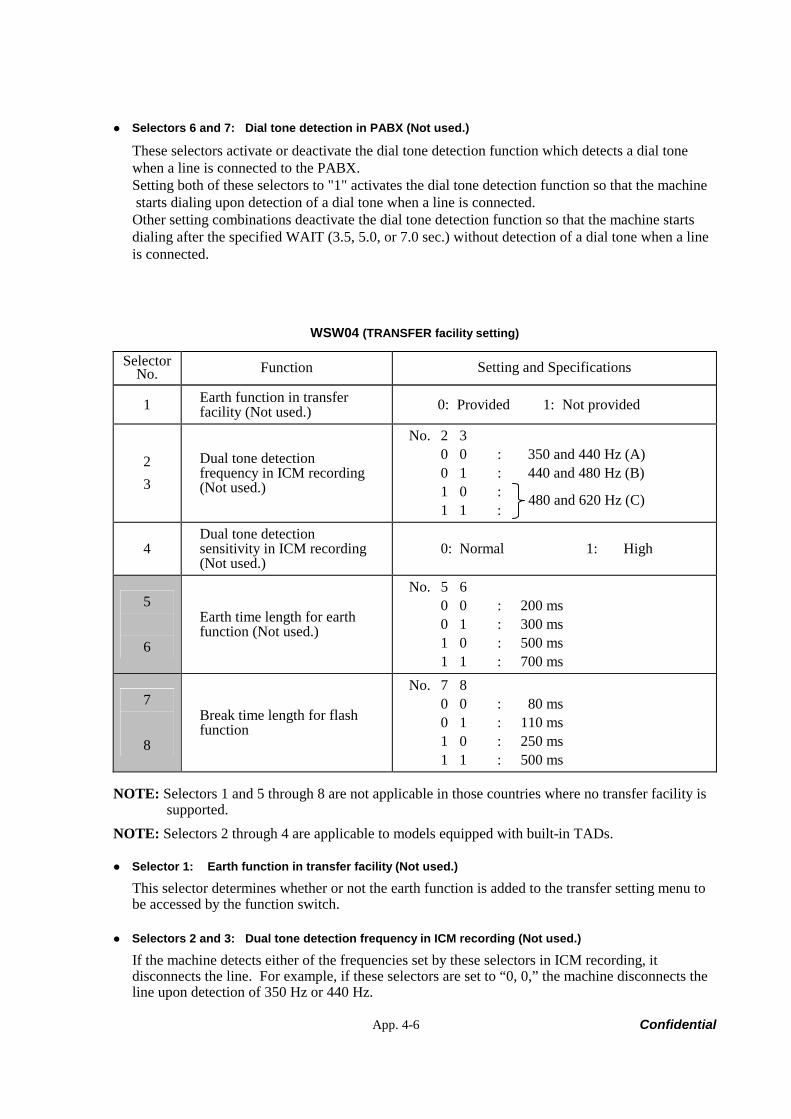
App. 4-6 Confidential
Selectors 6 and 7: Dial tone detection in PABX (Not used.)
These selectors activate or deactivate the dial tone detection function which detects a dial tone when a line is connected to the PABX. Setting both of these selectors to "1" activates the dial tone detection function so that the machine starts dialing upon detection of a dial tone when a line is connected. Other setting combinations deactivate the dial tone detection function so that the machine starts dialing after the specified WAIT (3.5, 5.0, or 7.0 sec.) without detection of a dial tone when a line is connected.
WSW04 (TRANSFER facility setting)
Selector No. Function Setting and Specifications
1 Earth function in transfer facility (Not used.) 0: Provided 1: Not provided
2 3
Dual tone detection frequency in ICM recording (Not used.)
No. 2 3 0 0 : 350 and 440 Hz (A) 0 1 : 440 and 480 Hz (B) 1 0 : 1 1 :
4 Dual tone detection sensitivity in ICM recording (Not used.)
0: Normal 1: High
5
6
Earth time length for earth function (Not used.)
No. 5 6 0 0 : 200 ms 0 1 : 300 ms 1 0 : 500 ms 1 1 : 700 ms
7
8
Break time length for flash function
No. 7 8 0 0 : 80 ms 0 1 : 110 ms 1 0 : 250 ms 1 1 : 500 ms
NOTE: Selectors 1 and 5 through 8 are not applicable in those countries where no transfer facility is supported.
NOTE: Selectors 2 through 4 are applicable to models equipped with built-in TADs.
Selector 1: Earth function in transfer facility (Not used.)
This selector determines whether or not the earth function is added to the transfer setting menu to be accessed by the function switch.
Selectors 2 and 3: Dual tone detection frequency in ICM recording (Not used.)
If the machine detects either of the frequencies set by these selectors in ICM recording, it disconnects the line. For example, if these selectors are set to “0, 0,” the machine disconnects the line upon detection of 350 Hz or 440 Hz.
480 and 620 Hz (C)
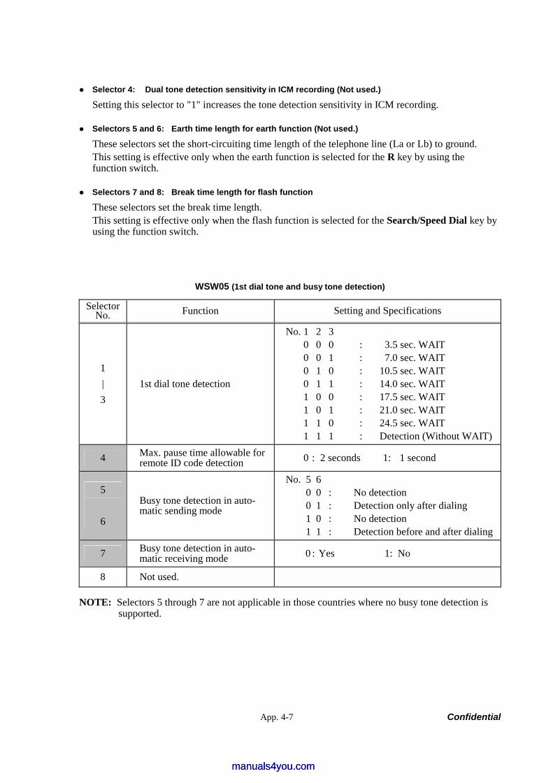
App. 4-7 Confidential
Selector 4: Dual tone detection sensitivity in ICM recording (Not used.)
Setting this selector to "1" increases the tone detection sensitivity in ICM recording.
Selectors 5 and 6: Earth time length for earth function (Not used.)
These selectors set the short-circuiting time length of the telephone line (La or Lb) to ground. This setting is effective only when the earth function is selected for the R key by using the function switch.
Selectors 7 and 8: Break time length for flash function
These selectors set the break time length. This setting is effective only when the flash function is selected for the Search/Speed Dial key by using the function switch.
WSW05 (1st dial tone and busy tone detection)
Selector No. Function Setting and Specifications
1 | 3
1st dial tone detection
No. 1 2 3 0 0 0 : 3.5 sec. WAIT 0 0 1 : 7.0 sec. WAIT 0 1 0 : 10.5 sec. WAIT 0 1 1 : 14.0 sec. WAIT 1 0 0 : 17.5 sec. WAIT 1 0 1 : 21.0 sec. WAIT 1 1 0 : 24.5 sec. WAIT 1 1 1 : Detection (Without WAIT)
4 Max. pause time allowable for remote ID code detection 0 : 2 seconds 1: 1 second
5
6
Busy tone detection in auto-matic sending mode
No. 5 6 0 0 : No detection 0 1 : Detection only after dialing 1 0 : No detection 1 1 : Detection before and after dialing
7 Busy tone detection in auto-matic receiving mode 0 : Yes 1: No
8 Not used.
NOTE: Selectors 5 through 7 are not applicable in those countries where no busy tone detection is supported.
manuals4you.commanuals4you.com
App. 4-8 Confidential
Selectors 1 through 3: 1st dial tone detection
These selectors activate or deactivate the 1st dial tone detection function which detects the 1st dial tone issued from the PSTN when a line is connected to the PSTN. Setting all of these selectors to "1" activates the dial tone detection function so that the machine starts dialing upon detection of a dial tone when a line is connected. (However, in those countries which support no dial tone detection function, e.g., in the U.S.A., setting these selectors to "1" makes the machine start dialing after a WAIT of 3.5 seconds.) For the detecting conditions of the 1st dial tone, refer to WSW07 and WSW08. Other setting combinations deactivate the dial tone detection function so that the machine starts dialing after the specified WAIT (3.5, 7.0, 10.5, 14.0, 17.5, 21.0, or 24.5 seconds) without detection of a dial tone when a line is connected to the PSTN.
Selector 4: Max. pause time allowable for remote ID code detection
This selector sets the maximum pause time allowable for detecting the second digit of a remote ID code after detection of the first digit in remote reception. If selector 4 is set to "0" (2 seconds), for instance, only a remote ID code whose second digit is detected within 2 seconds after detection of the first digit will become effective so as to activate the remote function.
Selectors 5 and 6: Busy tone detection in automatic sending mode
These selectors determine whether or not the machine automatically disconnects a line upon detection of a busy tone in automatic sending mode. Setting selector 6 to "0" ignores a busy tone so that the machine does not disconnect the line. Setting selectors 5 and 6 to "0" and "1," respectively, makes the machine detect a busy tone only after dialing and disconnect the line. Setting both of selectors 5 and 6 to "1" makes the machine detect a busy tone before and after dialing and then disconnect the line.
Selector 7: Busy tone detection in automatic receiving mode
This selector determines whether or not the machine automatically disconnects the line upon detection of a busy tone in automatic receiving mode.
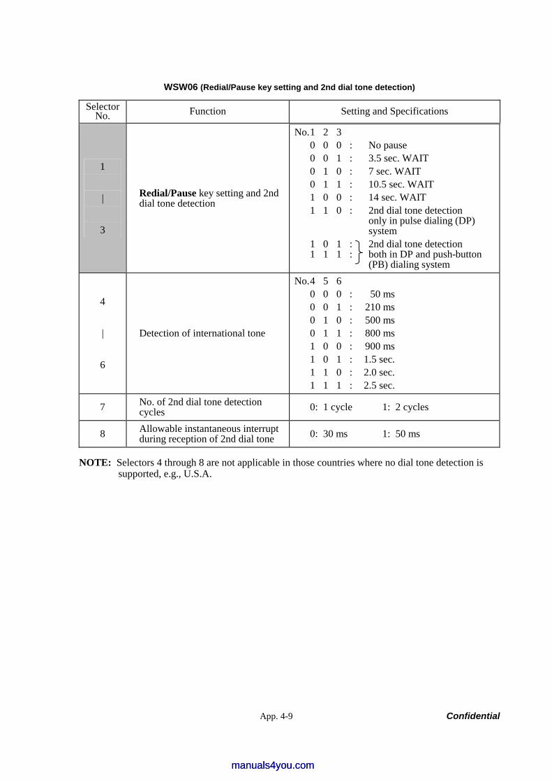
App. 4-9 Confidential
WSW06 (Redial/Pause key setting and 2nd dial tone detection)
Selector No. Function Setting and Specifications
1 |
3
Redial/Pause key setting and 2nd dial tone detection
No. 1 2 3 0 0 0 : No pause 0 0 1 : 3.5 sec. WAIT 0 1 0 : 7 sec. WAIT 0 1 1 : 10.5 sec. WAIT 1 0 0 : 14 sec. WAIT 1 1 0 : 2nd dial tone detection only in pulse dialing (DP) system 1 0 1 : 2nd dial tone detection 1 1 1 : both in DP and push-button (PB) dialing system
4 |
6
Detection of international tone
No. 4 5 6 0 0 0 : 50 ms 0 0 1 : 210 ms 0 1 0 : 500 ms 0 1 1 : 800 ms 1 0 0 : 900 ms 1 0 1 : 1.5 sec. 1 1 0 : 2.0 sec. 1 1 1 : 2.5 sec.
7 No. of 2nd dial tone detection cycles 0: 1 cycle 1: 2 cycles
8 Allowable instantaneous interrupt during reception of 2nd dial tone 0: 30 ms 1: 50 ms
NOTE: Selectors 4 through 8 are not applicable in those countries where no dial tone detection is supported, e.g., U.S.A.
manuals4you.commanuals4you.com
App. 4-10 Confidential
Selectors 1 through 3: Redial/Pause key setting and 2nd dial tone detection
Selectors 1 2 3
0 0 0 No WAIT is inserted even if the Redial/Pause key is pressed. 0 0 1 0 1 0 0 1 1 1 0 0
If you press the Redial/Pause key during dialing, the machine will insert WAIT as defined in the above table. If the Redial/Pause key is pressed repeatedly, the machine inserts the specified WAIT multiplied by the number of depressions. It applies also in hook-up dialing.
1 0 1 1 1 0 1 1 1
When these selectors are set to "1, 0, 1": Each time you press the Redial/Pause key in dialing, the machine will wait for the 2nd dial tone to be sent via the communications line regardless of pulse dialing or tone dialing. When these selectors are set to "1, 1, 0": If you press the Redial/Pause key in pulse dialing, the machine will first wait for the 2nd dial tone to be sent via the communications line. After that, pressing the Redial/Pause key will cause the machine to insert a WAIT of 3.5 seconds. In tone dialing, the machine will insert a WAIT of 3.5 seconds. When these selectors are set to "1, 1, 1": If you press the Redial/Pause key, the machine will first wait for the 2nd dial tone to be sent via the communications line regardless of pulse dialing or tone dialing. After that, pressing the Redial/Pause key will cause the machine to insert a WAIT of 3.5 seconds. (In those countries where no dial tone detection function is supported, setting these selectors to "1, 0, 1," "1, 1, 0," or "1, 1, 1" inserts a WAIT of 3.5 seconds.)
Selectors 4 through 6: Detection of international tone
Upon detection of the 2nd dial tone for the time length specified by these selectors, the machine starts dialing. This setting is effective only when the 2nd dial tone detection function is activated by selectors 1 through 3 (Setting 101, 110, or 111). This function does not apply in those countries where no dial tone detection function is supported.
Selector 7: No. of 2nd dial tone detection cycles
This selector sets the number of dial tone detection cycles required for starting dialing.
Selector 8: Allowable instantaneous interrupt during reception of 2nd dial tone
This selector sets the allowable instantaneous interrupt period that should be ignored during reception of the 2nd dial tone.
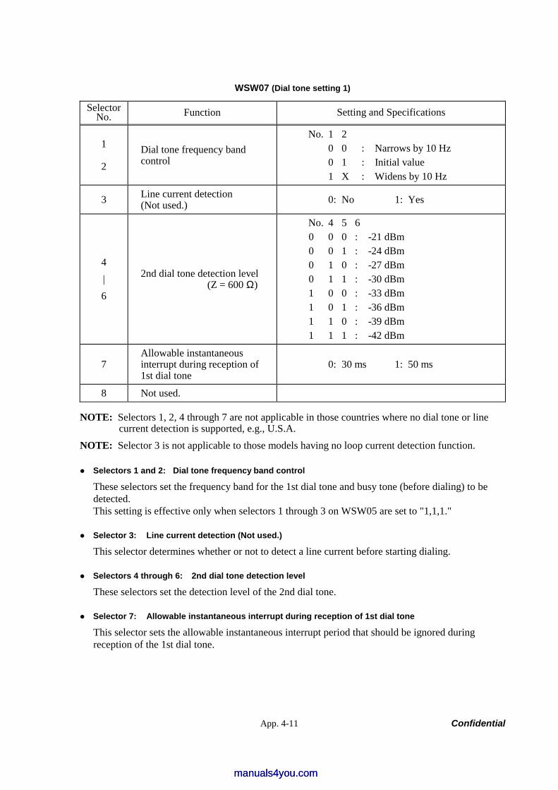
App. 4-11 Confidential
WSW07 (Dial tone setting 1)
Selector No. Function Setting and Specifications
1
2 Dial tone frequency band control
No. 1 2 0 0 : Narrows by 10 Hz 0 1 : Initial value 1 X : Widens by 10 Hz
3 Line current detection (Not used.) 0: No 1: Yes
4 | 6
2nd dial tone detection level (Z = 600 Ω)
No. 4 5 6 0 0 0 : -21 dBm 0 0 1 : -24 dBm 0 1 0 : -27 dBm 0 1 1 : -30 dBm 1 0 0 : -33 dBm 1 0 1 : -36 dBm 1 1 0 : -39 dBm 1 1 1 : -42 dBm
7 Allowable instantaneous interrupt during reception of 1st dial tone
0: 30 ms 1: 50 ms
8 Not used.
NOTE: Selectors 1, 2, 4 through 7 are not applicable in those countries where no dial tone or line current detection is supported, e.g., U.S.A.
NOTE: Selector 3 is not applicable to those models having no loop current detection function.
Selectors 1 and 2: Dial tone frequency band control
These selectors set the frequency band for the 1st dial tone and busy tone (before dialing) to be detected. This setting is effective only when selectors 1 through 3 on WSW05 are set to "1,1,1."
Selector 3: Line current detection (Not used.)
This selector determines whether or not to detect a line current before starting dialing.
Selectors 4 through 6: 2nd dial tone detection level
These selectors set the detection level of the 2nd dial tone.
Selector 7: Allowable instantaneous interrupt during reception of 1st dial tone
This selector sets the allowable instantaneous interrupt period that should be ignored during reception of the 1st dial tone.
manuals4you.commanuals4you.com
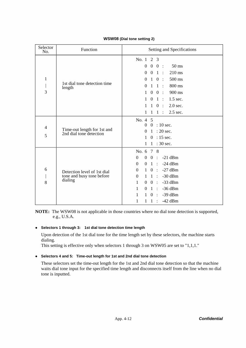
App. 4-12 Confidential
WSW08 (Dial tone setting 2)
Selector No. Function Setting and Specifications
1 | 3
1st dial tone detection time length
No. 1 2 3 0 0 0 : 50 ms 0 0 1 : 210 ms 0 1 0 : 500 ms 0 1 1 : 800 ms 1 0 0 : 900 ms 1 0 1 : 1.5 sec. 1 1 0 : 2.0 sec. 1 1 1 : 2.5 sec.
4
5 Time-out length for 1st and 2nd dial tone detection
No. 4 5 0 0 : 10 sec. 0 1 : 20 sec. 1 0 : 15 sec. 1 1 : 30 sec.
6 | 8
Detection level of 1st dial tone and busy tone before dialing
No. 6 7 8 0 0 0 : -21 dBm 0 0 1 : -24 dBm 0 1 0 : -27 dBm 0 1 1 : -30 dBm 1 0 0 : -33 dBm 1 0 1 : -36 dBm 1 1 0 : -39 dBm 1 1 1 : -42 dBm
NOTE: The WSW08 is not applicable in those countries where no dial tone detection is supported, e.g., U.S.A.
Selectors 1 through 3: 1st dial tone detection time length
Upon detection of the 1st dial tone for the time length set by these selectors, the machine starts dialing. This setting is effective only when selectors 1 through 3 on WSW05 are set to "1,1,1."
Selectors 4 and 5: Time-out length for 1st and 2nd dial tone detection
These selectors set the time-out length for the 1st and 2nd dial tone detection so that the machine waits dial tone input for the specified time length and disconnects itself from the line when no dial tone is inputted.
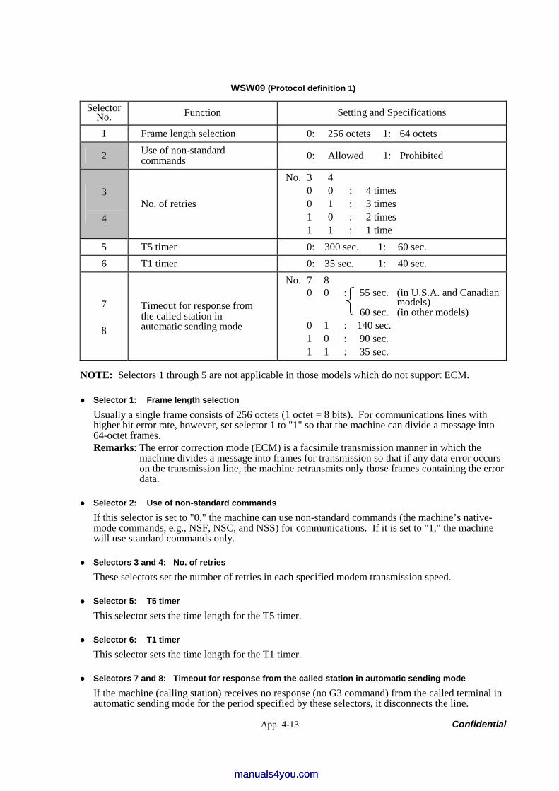
App. 4-13 Confidential
WSW09 (Protocol definition 1)
Selector No. Function Setting and Specifications
1 Frame length selection 0: 256 octets 1: 64 octets
2 Use of non-standard commands 0: Allowed 1: Prohibited
3
4 No. of retries
No. 3 4 0 0 : 4 times 0 1 : 3 times 1 0 : 2 times 1 1 : 1 time
5 T5 timer 0: 300 sec. 1: 60 sec. 6 T1 timer 0: 35 sec. 1: 40 sec.
7
8
Timeout for response from the called station in automatic sending mode
No. 7 8 0 0 : 55 sec. (in U.S.A. and Canadian models) 60 sec. (in other models) 0 1 : 140 sec. 1 0 : 90 sec. 1 1 : 35 sec.
NOTE: Selectors 1 through 5 are not applicable in those models which do not support ECM.
Selector 1: Frame length selection
Usually a single frame consists of 256 octets (1 octet = 8 bits). For communications lines with higher bit error rate, however, set selector 1 to "1" so that the machine can divide a message into 64-octet frames. Remarks: The error correction mode (ECM) is a facsimile transmission manner in which the
machine divides a message into frames for transmission so that if any data error occurs on the transmission line, the machine retransmits only those frames containing the error data.
Selector 2: Use of non-standard commands
If this selector is set to "0," the machine can use non-standard commands (the machine’s native- mode commands, e.g., NSF, NSC, and NSS) for communications. If it is set to "1," the machine will use standard commands only.
Selectors 3 and 4: No. of retries
These selectors set the number of retries in each specified modem transmission speed.
Selector 5: T5 timer
This selector sets the time length for the T5 timer.
Selector 6: T1 timer
This selector sets the time length for the T1 timer.
Selectors 7 and 8: Timeout for response from the called station in automatic sending mode
If the machine (calling station) receives no response (no G3 command) from the called terminal in automatic sending mode for the period specified by these selectors, it disconnects the line.
manuals4you.commanuals4you.com
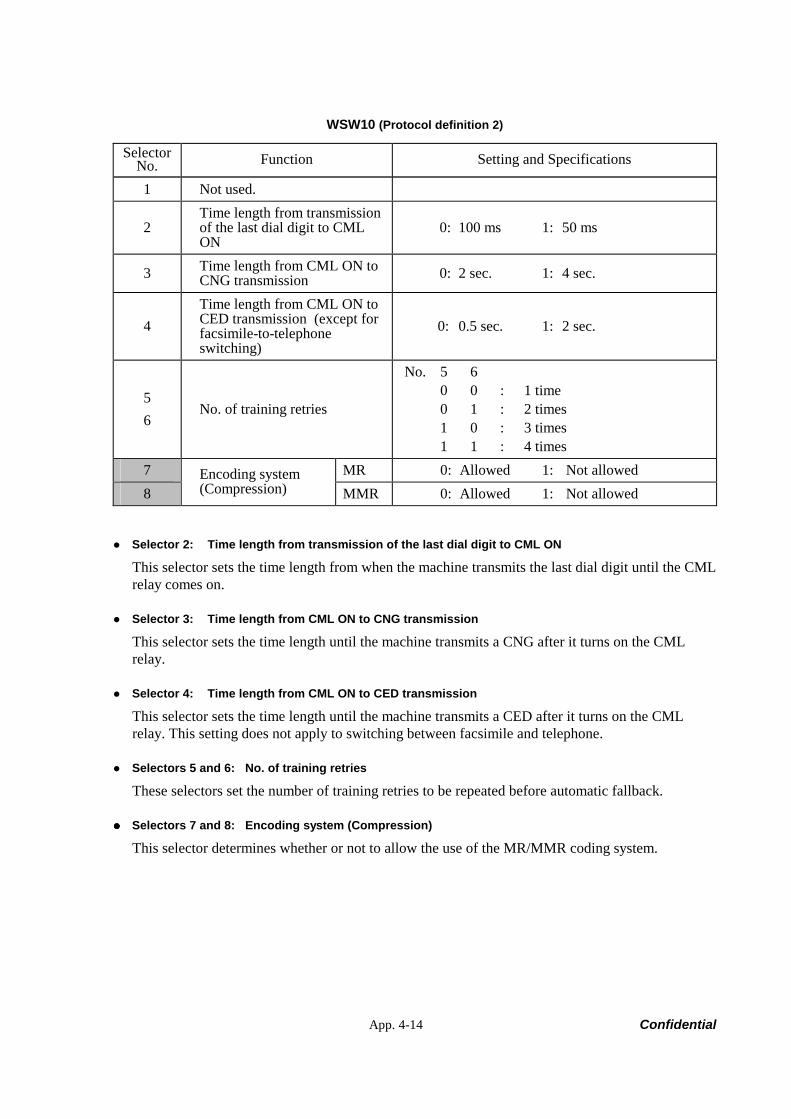
App. 4-14 Confidential
WSW10 (Protocol definition 2)
Selector No. Function Setting and Specifications
1 Not used.
2 Time length from transmission of the last dial digit to CML ON
0: 100 ms 1: 50 ms
3 Time length from CML ON to CNG transmission 0: 2 sec. 1: 4 sec.
4 Time length from CML ON to CED transmission (except for facsimile-to-telephone switching)
0: 0.5 sec. 1: 2 sec.
5 6
No. of training retries
No. 5 6 0 0 : 1 time 0 1 : 2 times 1 0 : 3 times 1 1 : 4 times
7 MR 0: Allowed 1: Not allowed 8
Encoding system (Compression) MMR 0: Allowed 1: Not allowed
Selector 2: Time length from transmission of the last dial digit to CML ON
This selector sets the time length from when the machine transmits the last dial digit until the CML relay comes on.
Selector 3: Time length from CML ON to CNG transmission
This selector sets the time length until the machine transmits a CNG after it turns on the CML relay.
Selector 4: Time length from CML ON to CED transmission
This selector sets the time length until the machine transmits a CED after it turns on the CML relay. This setting does not apply to switching between facsimile and telephone.
Selectors 5 and 6: No. of training retries
These selectors set the number of training retries to be repeated before automatic fallback.
Selectors 7 and 8: Encoding system (Compression)
This selector determines whether or not to allow the use of the MR/MMR coding system.
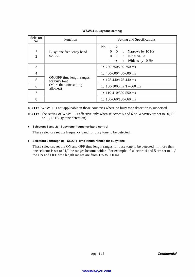
App. 4-15 Confidential
WSW11 (Busy tone setting)
Selector No. Function Setting and Specifications
1 2
Busy tone frequency band control
No. 1 2 0 0 : Narrows by 10 Hz 0 1 : Initial value 1 x : Widens by 10 Hz
3 1: 250-750/250-750 ms
4 1: 400-600/400-600 ms
5 1: 175-440/175-440 ms
6 1: 100-1000 ms/17-660 ms
7 1: 110-410/320-550 ms
8
ON/OFF time length ranges for busy tone (More than one setting allowed)
1: 100-660/100-660 ms
NOTE: WSW11 is not applicable in those countries where no busy tone detection is supported. NOTE: The setting of WSW11 is effective only when selectors 5 and 6 on WSW05 are set to "0, 1"
or "1, 1" (Busy tone detection).
Selectors 1 and 2: Busy tone frequency band control
These selectors set the frequency band for busy tone to be detected.
Selectors 3 through 8: ON/OFF time length ranges for busy tone
These selectors set the ON and OFF time length ranges for busy tone to be detected. If more than one selector is set to "1," the ranges become wider. For example, if selectors 4 and 5 are set to "1," the ON and OFF time length ranges are from 175 to 600 ms.
manuals4you.commanuals4you.com
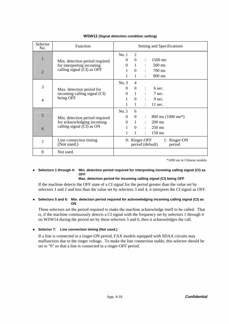
App. 4-16 Confidential
WSW12 (Signal detection condition setting)
Selector No. Function Setting and Specifications
1
2
Min. detection period required for interpreting incoming calling signal (CI) as OFF
No. 1 2 0 0 : 1500 ms 0 1 : 500 ms 1 0 : 700 ms 1 1 : 900 ms
3
4
Max. detection period for incoming calling signal (CI) being OFF
No. 3 4 0 0 : 6 sec. 0 1 : 7 sec. 1 0 : 9 sec. 1 1 : 11 sec.
5
6
Min. detection period required for acknowledging incoming calling signal (CI) as ON
No. 5 6 0 0 : 800 ms (1000 ms*) 0 1 : 200 ms 1 0 : 250 ms 1 1 : 150 ms
7 Line connection timing (Not used.)
0: Ringer-OFF 1: Ringer-ON period (default) period
8 Not used.
*1000 ms in Chinese models.
Selectors 1 through 4: Min. detection period required for interpreting incoming calling signal (CI) as OFF Max. detection period for incoming calling signal (CI) being OFF
If the machine detects the OFF state of a CI signal for the period greater than the value set by selectors 1 and 2 and less than the value set by selectors 3 and 4, it interprets the CI signal as OFF.
Selectors 5 and 6: Min. detection period required for acknowledging incoming calling signal (CI) as ON
These selectors set the period required to make the machine acknowledge itself to be called. That is, if the machine continuously detects a CI signal with the frequency set by selectors 1 through 4 on WSW14 during the period set by these selectors 5 and 6, then it acknowledges the call.
Selector 7: Line connection timing (Not used.)
If a line is connected in a ringer-ON period, FAX models equipped with SDAA circuits may malfunction due to the ringer voltage. To make the line connection stable, this selector should be set to "0" so that a line is connected in a ringer-OFF period.
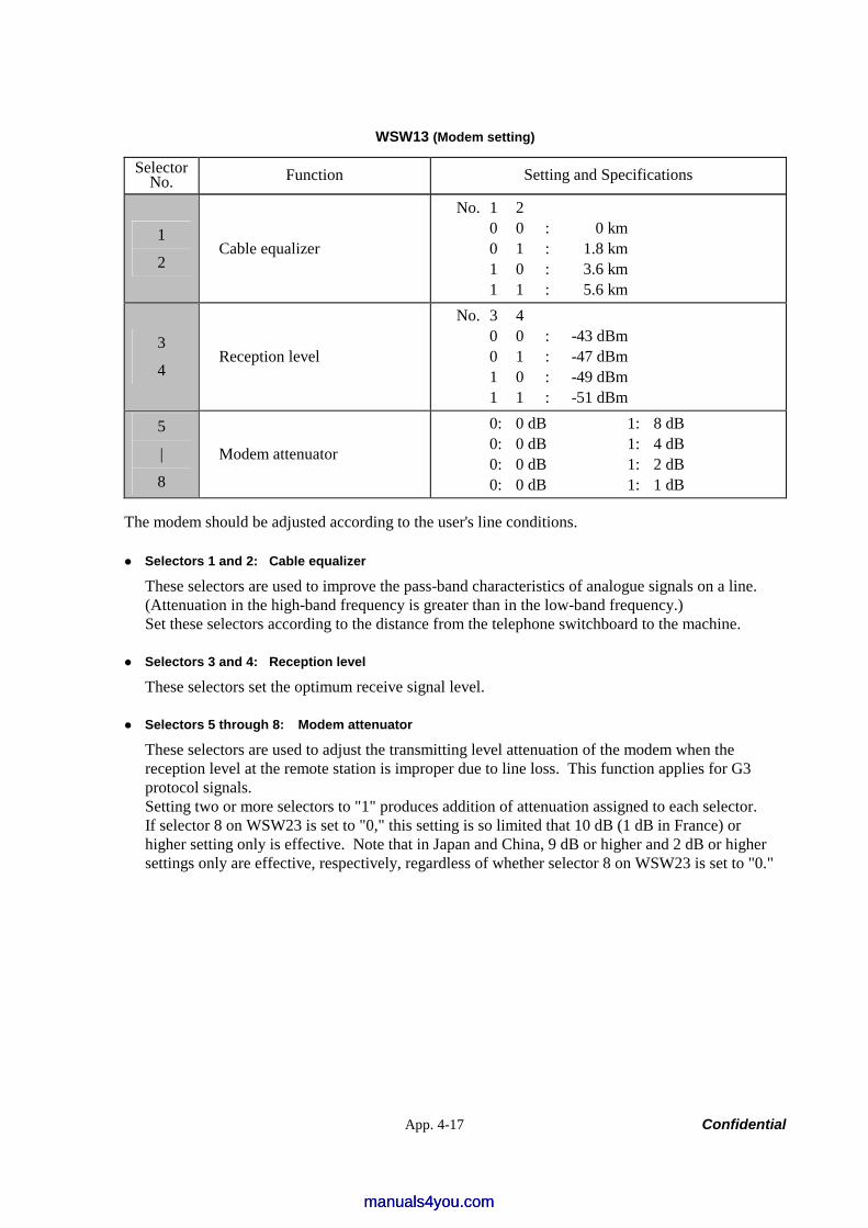
App. 4-17 Confidential
WSW13 (Modem setting)
Selector No. Function Setting and Specifications
1
2 Cable equalizer
No. 1 2 0 0 : 0 km 0 1 : 1.8 km 1 0 : 3.6 km 1 1 : 5.6 km
3
4 Reception level
No. 3 4 0 0 : -43 dBm 0 1 : -47 dBm 1 0 : -49 dBm 1 1 : -51 dBm
5
|
8
Modem attenuator
0: 0 dB 1: 8 dB 0: 0 dB 1: 4 dB 0: 0 dB 1: 2 dB 0: 0 dB 1: 1 dB
The modem should be adjusted according to the user's line conditions.
Selectors 1 and 2: Cable equalizer
These selectors are used to improve the pass-band characteristics of analogue signals on a line. (Attenuation in the high-band frequency is greater than in the low-band frequency.) Set these selectors according to the distance from the telephone switchboard to the machine.
Selectors 3 and 4: Reception level
These selectors set the optimum receive signal level.
Selectors 5 through 8: Modem attenuator
These selectors are used to adjust the transmitting level attenuation of the modem when the reception level at the remote station is improper due to line loss. This function applies for G3 protocol signals. Setting two or more selectors to "1" produces addition of attenuation assigned to each selector. If selector 8 on WSW23 is set to "0," this setting is so limited that 10 dB (1 dB in France) or higher setting only is effective. Note that in Japan and China, 9 dB or higher and 2 dB or higher settings only are effective, respectively, regardless of whether selector 8 on WSW23 is set to "0."
manuals4you.commanuals4you.com
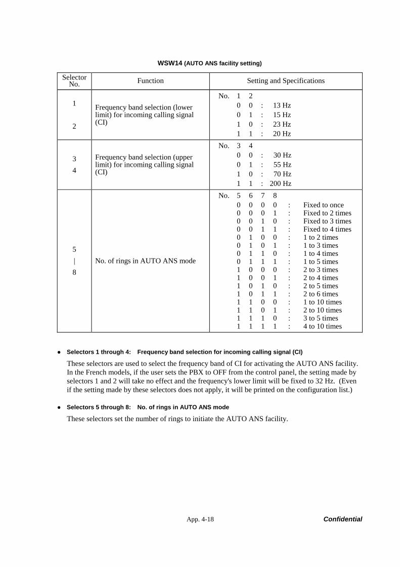
App. 4-18 Confidential
WSW14 (AUTO ANS facility setting)
Selector No. Function Setting and Specifications
1
2
Frequency band selection (lower limit) for incoming calling signal (CI)
No. 1 2 0 0 : 13 Hz 0 1 : 15 Hz 1 0 : 23 Hz 1 1 : 20 Hz
3 4
Frequency band selection (upper limit) for incoming calling signal (CI)
No. 3 4 0 0 : 30 Hz 0 1 : 55 Hz 1 0 : 70 Hz 1 1 : 200 Hz
5 | 8
No. of rings in AUTO ANS mode
No. 5 6 7 8 0 0 0 0 : Fixed to once 0 0 0 1 : Fixed to 2 times 0 0 1 0 : Fixed to 3 times 0 0 1 1 : Fixed to 4 times 0 1 0 0 : 1 to 2 times 0 1 0 1 : 1 to 3 times 0 1 1 0 : 1 to 4 times 0 1 1 1 : 1 to 5 times 1 0 0 0 : 2 to 3 times 1 0 0 1 : 2 to 4 times 1 0 1 0 : 2 to 5 times 1 0 1 1 : 2 to 6 times 1 1 0 0 : 1 to 10 times 1 1 0 1 : 2 to 10 times 1 1 1 0 : 3 to 5 times 1 1 1 1 : 4 to 10 times
Selectors 1 through 4: Frequency band selection for incoming calling signal (CI)
These selectors are used to select the frequency band of CI for activating the AUTO ANS facility. In the French models, if the user sets the PBX to OFF from the control panel, the setting made by selectors 1 and 2 will take no effect and the frequency's lower limit will be fixed to 32 Hz. (Even if the setting made by these selectors does not apply, it will be printed on the configuration list.)
Selectors 5 through 8: No. of rings in AUTO ANS mode
These selectors set the number of rings to initiate the AUTO ANS facility.

App. 4-19 Confidential
WSW15 (REDIAL facility setting)
Selector No. Function Setting and Specifications
1
2
Redial interval
No. 1 2 0 0 : 5 minutes 0 1 : 1 minute 1 0 : 2 minutes 1 1 : 3 minutes
3
|
6
No. of redialings
No. 3 4 5 6 0 0 0 0 : 16 times 0 0 0 1 : 1 times 0 0 1 0 : 2 times 0 0 1 1 : 3 times | | 1 1 1 1 : 15 times
7 Not used.
8 CRP option 0: Disable 1: Enable
Selectors 1 through 6: Redial interval and No. of redialings
The machine redials by the number of times set by selectors 3 through 6 at intervals set by selectors 1 and 2.
Selector 8: CRP option
If a command error occurs in the machine (calling station), the machine usually waits for three seconds and then makes a retry three times. This CRP option is a request command that can be sent from the called station for requesting the calling station to retry the failed command immediately.
manuals4you.commanuals4you.com
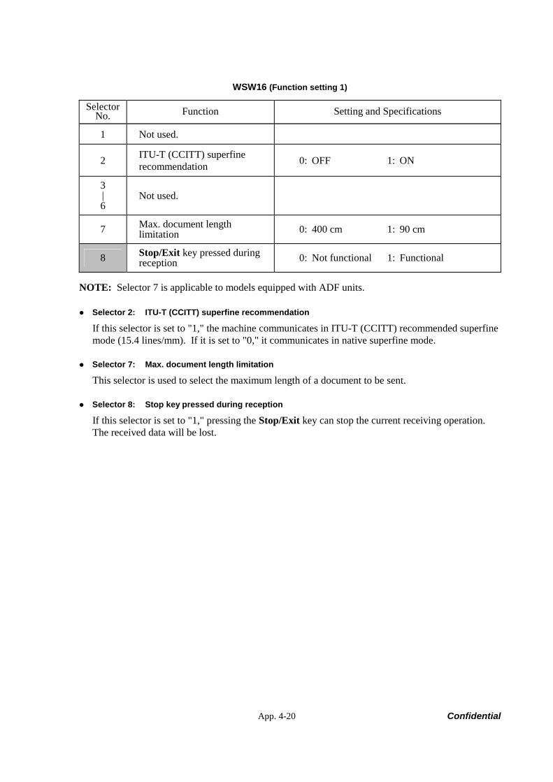
App. 4-20 Confidential
WSW16 (Function setting 1)
Selector No. Function Setting and Specifications
1 Not used.
2 ITU-T (CCITT) superfine recommendation 0: OFF 1: ON
3 | 6
Not used.
7 Max. document length limitation 0: 400 cm 1: 90 cm
8 Stop/Exit key pressed during reception 0: Not functional 1: Functional
NOTE: Selector 7 is applicable to models equipped with ADF units.
Selector 2: ITU-T (CCITT) superfine recommendation
If this selector is set to "1," the machine communicates in ITU-T (CCITT) recommended superfine mode (15.4 lines/mm). If it is set to "0," it communicates in native superfine mode.
Selector 7: Max. document length limitation
This selector is used to select the maximum length of a document to be sent.
Selector 8: Stop key pressed during reception
If this selector is set to "1," pressing the Stop/Exit key can stop the current receiving operation. The received data will be lost.
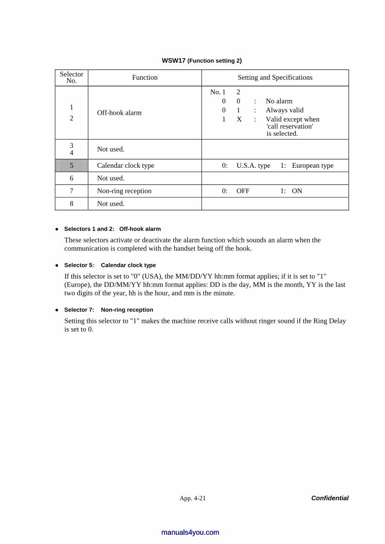
App. 4-21 Confidential
WSW17 (Function setting 2)
Selector No. Function Setting and Specifications
1 2
Off-hook alarm
No. 1 2 0 0 : No alarm 0 1 : Always valid 1 X : Valid except when
'call reservation' is selected.
3 4 Not used.
5 Calendar clock type 0: U.S.A. type 1: European type
6 Not used.
7 Non-ring reception 0: OFF 1: ON
8 Not used.
Selectors 1 and 2: Off-hook alarm
These selectors activate or deactivate the alarm function which sounds an alarm when the communication is completed with the handset being off the hook.
Selector 5: Calendar clock type
If this selector is set to "0" (USA), the MM/DD/YY hh:mm format applies; if it is set to "1" (Europe), the DD/MM/YY hh:mm format applies: DD is the day, MM is the month, YY is the last two digits of the year, hh is the hour, and mm is the minute.
Selector 7: Non-ring reception
Setting this selector to "1" makes the machine receive calls without ringer sound if the Ring Delay is set to 0.
manuals4you.commanuals4you.com
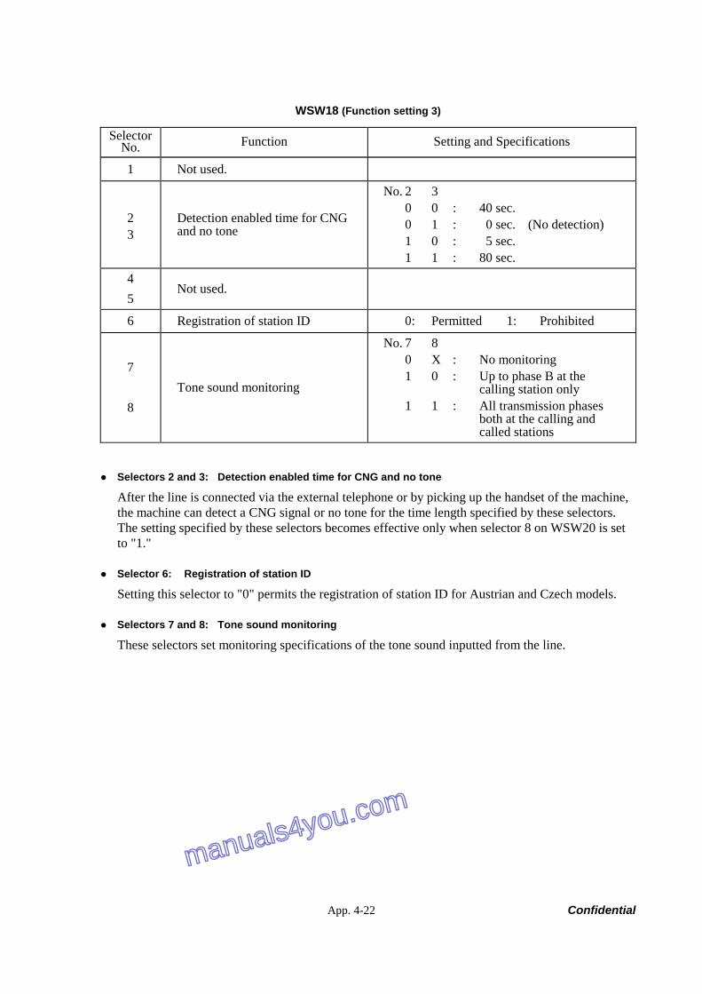
App. 4-22 Confidential
WSW18 (Function setting 3)
Selector No. Function Setting and Specifications
1 Not used.
2 3
Detection enabled time for CNG and no tone
No. 2 3 0 0 : 40 sec. 0 1 : 0 sec. (No detection) 1 0 : 5 sec. 1 1 : 80 sec.
4 5
Not used.
6 Registration of station ID 0: Permitted 1: Prohibited
7
8 Tone sound monitoring
No. 7 8 0 X : No monitoring 1 0 : Up to phase B at the calling station only 1 1 : All transmission phases both at the calling and called stations
Selectors 2 and 3: Detection enabled time for CNG and no tone
After the line is connected via the external telephone or by picking up the handset of the machine, the machine can detect a CNG signal or no tone for the time length specified by these selectors. The setting specified by these selectors becomes effective only when selector 8 on WSW20 is set to "1."
Selector 6: Registration of station ID
Setting this selector to "0" permits the registration of station ID for Austrian and Czech models.
Selectors 7 and 8: Tone sound monitoring
These selectors set monitoring specifications of the tone sound inputted from the line.
manuals4you.com
manuals4you.com
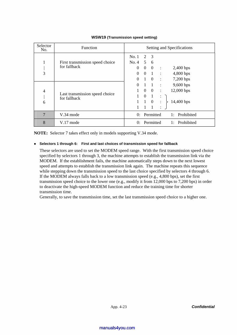
App. 4-23 Confidential
WSW19 (Transmission speed setting)
Selector No. Function Setting and Specifications
1 | 3
First transmission speed choice for fallback
No. 1 2 3 No. 4 5 6 0 0 0 : 2,400 bps 0 0 1 : 4,800 bps 0 1 0 : 7,200 bps
4 | 6
Last transmission speed choice for fallback
0 1 1 : 9,600 bps 1 0 0 : 12,000 bps 1 0 1 : 1 1 0 : 14,400 bps 1 1 1 :
7 V.34 mode 0: Permitted 1: Prohibited
8 V.17 mode 0: Permitted 1: Prohibited
NOTE: Selector 7 takes effect only in models supporting V.34 mode.
Selectors 1 through 6: First and last choices of transmission speed for fallback
These selectors are used to set the MODEM speed range. With the first transmission speed choice specified by selectors 1 through 3, the machine attempts to establish the transmission link via the MODEM. If the establishment fails, the machine automatically steps down to the next lowest speed and attempts to establish the transmission link again. The machine repeats this sequence while stepping down the transmission speed to the last choice specified by selectors 4 through 6. If the MODEM always falls back to a low transmission speed (e.g., 4,800 bps), set the first transmission speed choice to the lower one (e.g., modify it from 12,000 bps to 7,200 bps) in order to deactivate the high-speed MODEM function and reduce the training time for shorter transmission time. Generally, to save the transmission time, set the last transmission speed choice to a higher one.
manuals4you.commanuals4you.com

App. 4-24 Confidential
WSW20 (Overseas communications mode setting)
Selector No. Function Setting and Specifications
1 EP* tone prefix 0: OFF 1: ON
2 Overseas communications mode (Reception) 0: 2100 Hz 1: 1100 Hz
3 Overseas communications mode (Transmission) 0: OFF 1: Ignores DIS once.
4 5
Min. time length from reception of CFR to start of transmission of video signals
No. 4 5 0 0 : 100 ms 0 1 : 200 ms 1 0 : 300 ms 1 1 : 400 ms
6 7
At CNG detection, elimination of chattering noise
No. 6 7 0 0 : Yes, at both ON/OFF timings 0 1 : Yes, at OFF timing 1 X : No
8 Limitation on CNG detection 0: OFF 1: ON * EP: Echo protection
NOTE: Selectors 6 and 7 are applicable to models equipped with SDAA circuits.
Selector 1: EP tone prefix
Setting this selector to "1" makes the machine transmit a 1700 Hz echo protection (EP) tone immediately preceding training in V.29 modulation system to prevent omission of training signals. Prefixing an EP tone is useful when the machine fails to transmit at the V.29 modem speed and always has to fall back to 4800 bps transmission. The setting made by this selector takes effect only when the Overseas Mode is set to ON.
Selectors 2 and 3: Overseas communications mode
These selectors should be used if the machine malfunctions in overseas communications. According to the communications error state, select the signal specifications. Setting selector 2 to "1" allows the machine to use 1100 Hz CED signal instead of 2100 Hz in receiving operation. This prevents malfunctions resulting from echoes, since the 1100 Hz signal does not disable the echo suppressor (ES) while the 2100 Hz signal does. Setting selector 3 to "1" allows the machine to ignore a DIS signal sent from the called station once in sending operation. This operation suppresses echoes since the first DIS signal immediately follows a 2100 Hz CED (which disables the ES) so that it is likely to be affected by echoes in the disabled ES state. However, such a disabled ES state will be removed soon so that the second and the following DIS signals are not susceptible to data distortion due to echoes. Note that some models when called may cause error by receiving a self-outputted DIS. The setting made by selector 3 takes effect only when the Overseas Communications Mode is set to ON. (The setting made by selector 2 is always effective.)

App. 4-25 Confidential
Selectors 8: Limitation on CNG detection
If this selector is set to "1," the machine detects a CNG signal according to the condition preset by selectors 2 and 3 on WSW18 after a line is connected. If it is set to "0," the machine detects a CNG signal as long as the line is connected.
WSW21 (TAD setting 1)
Selector No. Function Setting and Specifications
1 | 5
Max. waiting time for voice signal (Not used.)
No. 1 2 3 4 5 0 0 0 0 0 : No detection 0 0 0 0 1 : 1 sec. 0 0 0 1 0 : 2 sec. 0 0 0 1 1 : 3 sec. | | 0 1 0 0 0 : 8 sec. | | 1 1 1 1 1 : 31 sec.
6 7 Taping the call (Not used.)
No. 6 7 0 0 : Enable (signaling for U.S.A.) 0 1 : Enable (signaling for countries
except U.S.A.) 1 0 : Enable (without signaling) 1 1 : Disable
8 Erasure of message stored in the memory after the message transfer
0: Yes 1: No
NOTE: Selectors 1 through 5 are applicable to models equipped with ICM recorders. NOTE: Selectors 6 and 7 are applicable to models with internal TADs. NOTE: Selector 8 is applicable to models equipped with TADs.
Selectors 1 through 5: Max. waiting time for voice signal (Not used.)
In the TAD mode, the machine waits for voice signal for the time length specified by these selectors before it automatically shifts to the facsimile message receive mode or disconnects the line.
Selectors 6 and 7: Taping the call (Not used.)
These selectors select whether or not to tape the call. Setting them to "1, 0" enables taping the call without signaling to the calling station that the call is being taped.
Selector 8: Erasure of message stored in the memory after the message transfer
Setting this selector to "0" will erase the message recorded in the memory after the document retrieval feature transfers the message.
manuals4you.commanuals4you.com
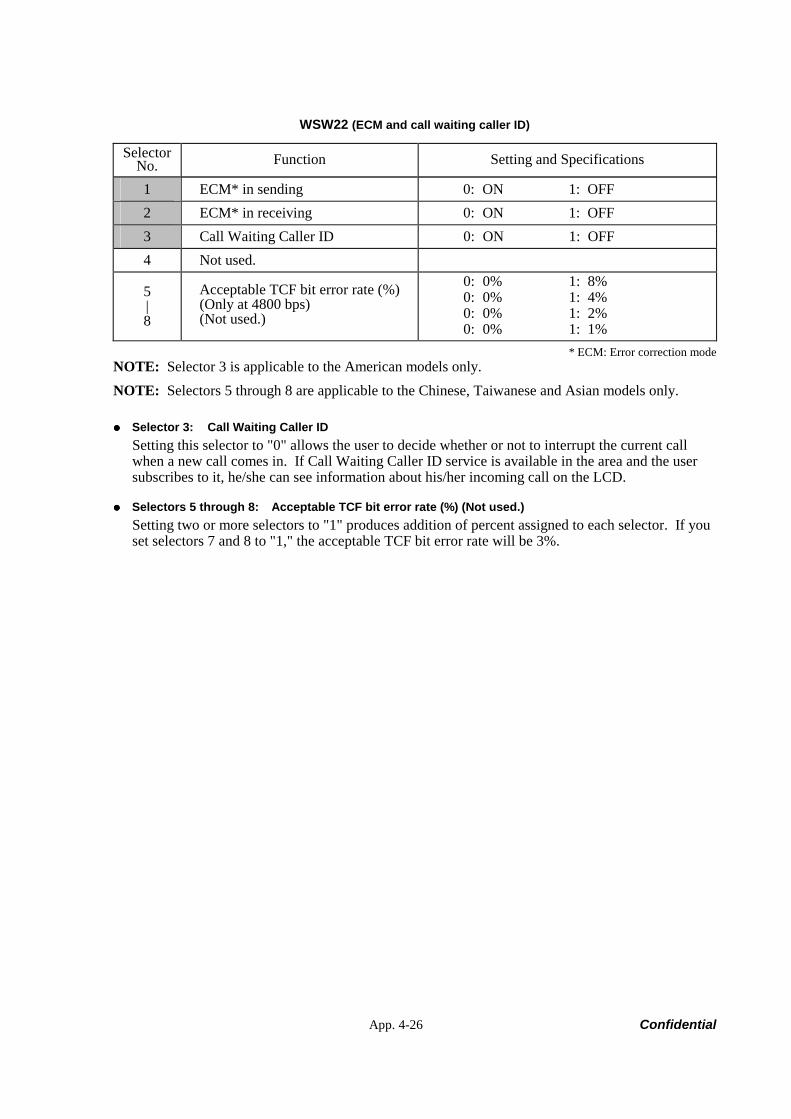
App. 4-26 Confidential
WSW22 (ECM and call waiting caller ID)
Selector No. Function Setting and Specifications
1 ECM* in sending 0: ON 1: OFF 2 ECM* in receiving 0: ON 1: OFF 3 Call Waiting Caller ID 0: ON 1: OFF 4 Not used.
5 | 8
Acceptable TCF bit error rate (%) (Only at 4800 bps) (Not used.)
0: 0% 1: 8% 0: 0% 1: 4% 0: 0% 1: 2% 0: 0% 1: 1%
* ECM: Error correction mode NOTE: Selector 3 is applicable to the American models only. NOTE: Selectors 5 through 8 are applicable to the Chinese, Taiwanese and Asian models only.
Selector 3: Call Waiting Caller ID Setting this selector to "0" allows the user to decide whether or not to interrupt the current call when a new call comes in. If Call Waiting Caller ID service is available in the area and the user subscribes to it, he/she can see information about his/her incoming call on the LCD.
Selectors 5 through 8: Acceptable TCF bit error rate (%) (Not used.) Setting two or more selectors to "1" produces addition of percent assigned to each selector. If you set selectors 7 and 8 to "1," the acceptable TCF bit error rate will be 3%.
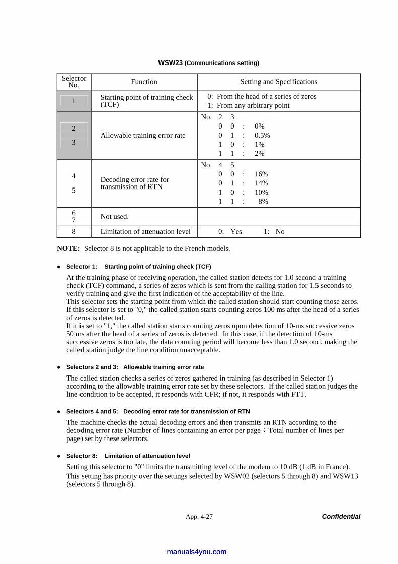
App. 4-27 Confidential
WSW23 (Communications setting)
Selector No. Function Setting and Specifications
1 Starting point of training check (TCF)
0: From the head of a series of zeros 1: From any arbitrary point
2
3 Allowable training error rate
No. 2 3 0 0 : 0% 0 1 : 0.5% 1 0 : 1% 1 1 : 2%
4
5 Decoding error rate for transmission of RTN
No. 4 5 0 0 : 16% 0 1 : 14% 1 0 : 10% 1 1 : 8%
6 7 Not used.
8 Limitation of attenuation level 0: Yes 1: No
NOTE: Selector 8 is not applicable to the French models.
Selector 1: Starting point of training check (TCF)
At the training phase of receiving operation, the called station detects for 1.0 second a training check (TCF) command, a series of zeros which is sent from the calling station for 1.5 seconds to verify training and give the first indication of the acceptability of the line. This selector sets the starting point from which the called station should start counting those zeros. If this selector is set to "0," the called station starts counting zeros 100 ms after the head of a series of zeros is detected. If it is set to "1," the called station starts counting zeros upon detection of 10-ms successive zeros 50 ms after the head of a series of zeros is detected. In this case, if the detection of 10-ms successive zeros is too late, the data counting period will become less than 1.0 second, making the called station judge the line condition unacceptable.
Selectors 2 and 3: Allowable training error rate
The called station checks a series of zeros gathered in training (as described in Selector 1) according to the allowable training error rate set by these selectors. If the called station judges the line condition to be accepted, it responds with CFR; if not, it responds with FTT.
Selectors 4 and 5: Decoding error rate for transmission of RTN
The machine checks the actual decoding errors and then transmits an RTN according to the decoding error rate (Number of lines containing an error per page ÷ Total number of lines per page) set by these selectors.
Selector 8: Limitation of attenuation level
Setting this selector to "0" limits the transmitting level of the modem to 10 dB (1 dB in France). This setting has priority over the settings selected by WSW02 (selectors 5 through 8) and WSW13 (selectors 5 through 8).
manuals4you.commanuals4you.com
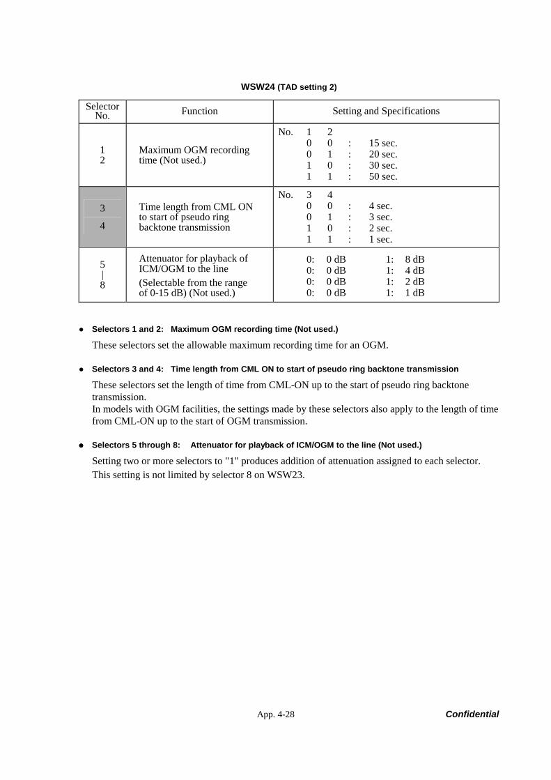
App. 4-28 Confidential
WSW24 (TAD setting 2)
Selector No. Function Setting and Specifications
1 2
Maximum OGM recording time (Not used.)
No. 1 2 0 0 : 15 sec. 0 1 : 20 sec. 1 0 : 30 sec. 1 1 : 50 sec.
3
4
Time length from CML ON to start of pseudo ring backtone transmission
No. 3 4 0 0 : 4 sec. 0 1 : 3 sec. 1 0 : 2 sec. 1 1 : 1 sec.
5 | 8
Attenuator for playback of ICM/OGM to the line (Selectable from the range of 0-15 dB) (Not used.)
0: 0 dB 1: 8 dB 0: 0 dB 1: 4 dB 0: 0 dB 1: 2 dB 0: 0 dB 1: 1 dB
Selectors 1 and 2: Maximum OGM recording time (Not used.)
These selectors set the allowable maximum recording time for an OGM.
Selectors 3 and 4: Time length from CML ON to start of pseudo ring backtone transmission
These selectors set the length of time from CML-ON up to the start of pseudo ring backtone transmission. In models with OGM facilities, the settings made by these selectors also apply to the length of time from CML-ON up to the start of OGM transmission.
Selectors 5 through 8: Attenuator for playback of ICM/OGM to the line (Not used.)
Setting two or more selectors to "1" produces addition of attenuation assigned to each selector. This setting is not limited by selector 8 on WSW23.
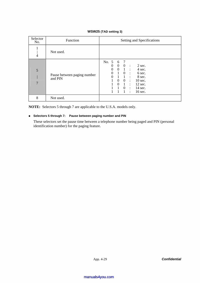
App. 4-29 Confidential
WSW25 (TAD setting 3)
Selector No. Function Setting and Specifications
1 | 4
Not used.
5
|
7
Pause between paging number and PIN
No. 5 6 7 0 0 0 : 2 sec. 0 0 1 : 4 sec. 0 1 0 : 6 sec. 0 1 1 : 8 sec. 1 0 0 : 10 sec. 1 0 1 : 12 sec. 1 1 0 : 14 sec. 1 1 1 : 16 sec.
8 Not used.
NOTE: Selectors 5 through 7 are applicable to the U.S.A. models only.
Selectors 5 through 7: Pause between paging number and PIN
These selectors set the pause time between a telephone number being paged and PIN (personal identification number) for the paging feature.
manuals4you.commanuals4you.com
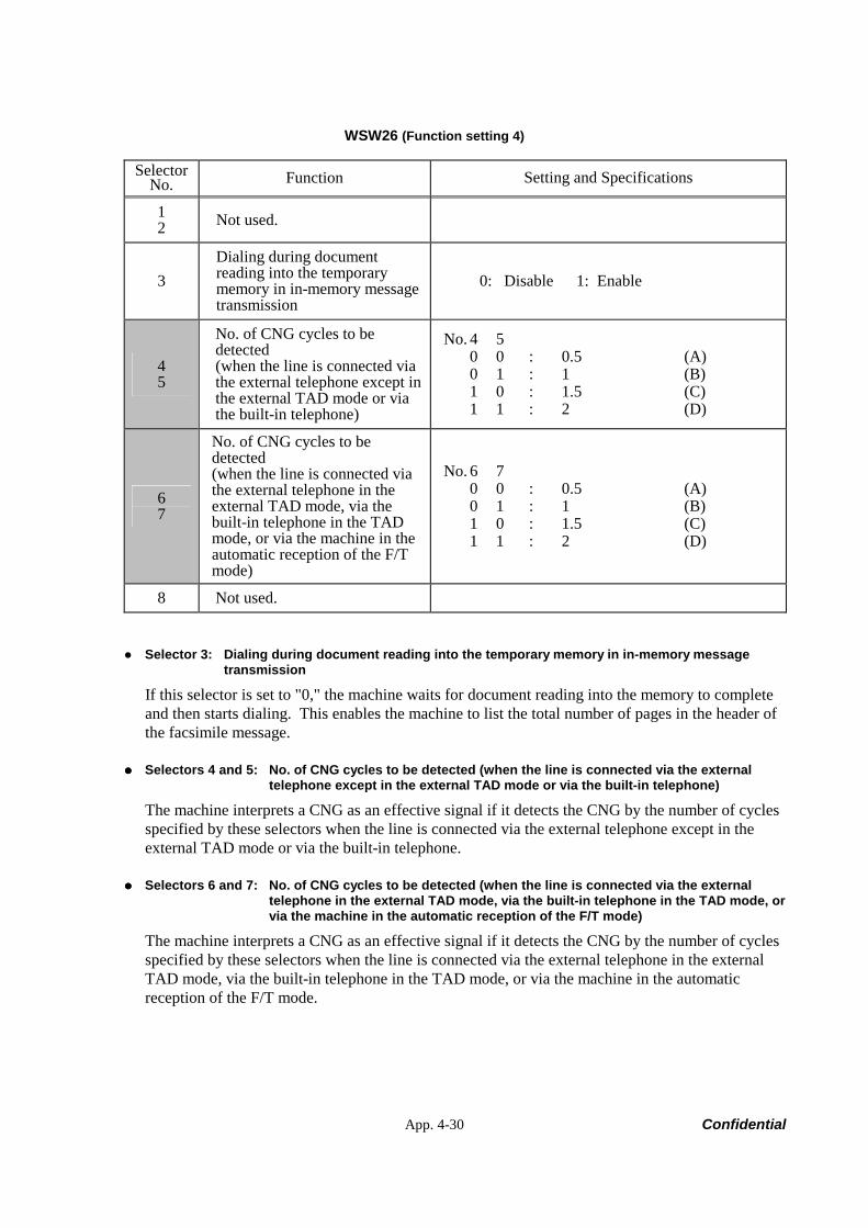
App. 4-30 Confidential
WSW26 (Function setting 4)
Selector No. Function Setting and Specifications
1 2 Not used.
3 Dialing during document reading into the temporary memory in in-memory message transmission
0: Disable 1: Enable
4 5
No. of CNG cycles to be detected (when the line is connected via the external telephone except in the external TAD mode or via the built-in telephone)
No. 4 5 0 0 : 0.5 (A) 0 1 : 1 (B) 1 0 : 1.5 (C) 1 1 : 2 (D)
6 7
No. of CNG cycles to be detected (when the line is connected via the external telephone in the external TAD mode, via the built-in telephone in the TAD mode, or via the machine in the automatic reception of the F/T mode)
No. 6 7 0 0 : 0.5 (A) 0 1 : 1 (B) 1 0 : 1.5 (C) 1 1 : 2 (D)
8 Not used.
Selector 3: Dialing during document reading into the temporary memory in in-memory message transmission
If this selector is set to "0," the machine waits for document reading into the memory to complete and then starts dialing. This enables the machine to list the total number of pages in the header of the facsimile message.
Selectors 4 and 5: No. of CNG cycles to be detected (when the line is connected via the external telephone except in the external TAD mode or via the built-in telephone)
The machine interprets a CNG as an effective signal if it detects the CNG by the number of cycles specified by these selectors when the line is connected via the external telephone except in the external TAD mode or via the built-in telephone.
Selectors 6 and 7: No. of CNG cycles to be detected (when the line is connected via the external telephone in the external TAD mode, via the built-in telephone in the TAD mode, or via the machine in the automatic reception of the F/T mode)
The machine interprets a CNG as an effective signal if it detects the CNG by the number of cycles specified by these selectors when the line is connected via the external telephone in the external TAD mode, via the built-in telephone in the TAD mode, or via the machine in the automatic reception of the F/T mode.
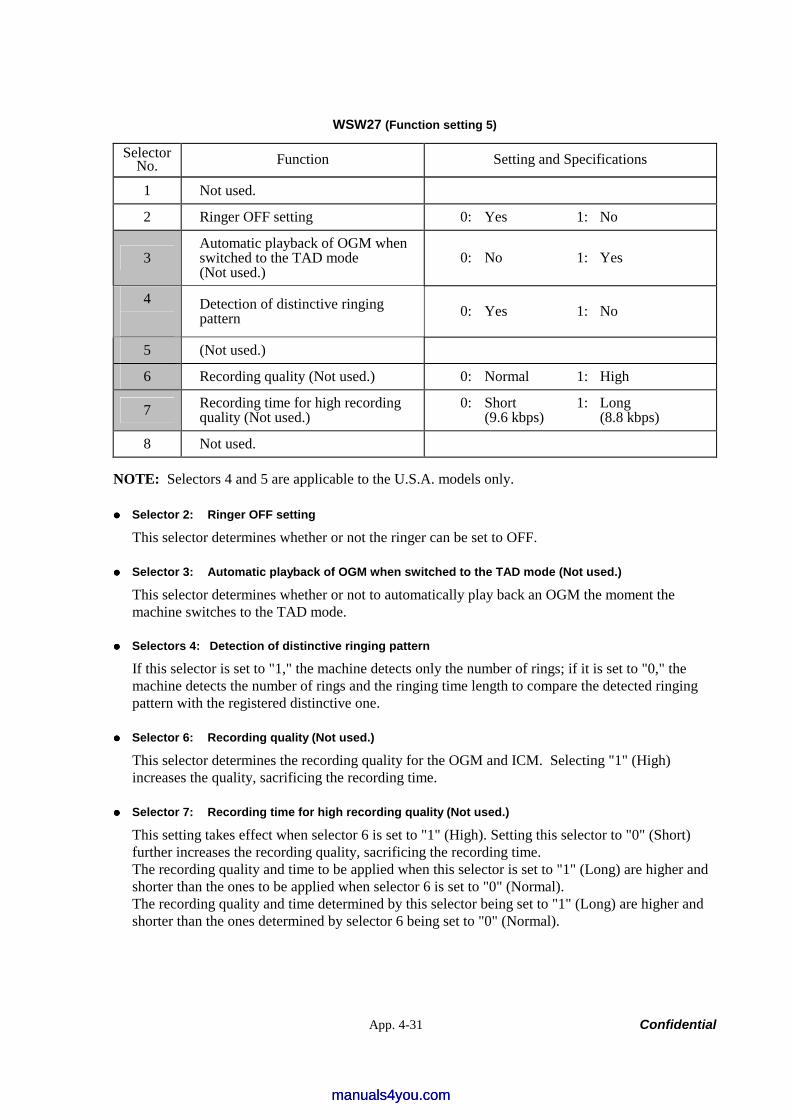
App. 4-31 Confidential
WSW27 (Function setting 5)
Selector No. Function Setting and Specifications
1 Not used.
2 Ringer OFF setting 0: Yes 1: No
3 Automatic playback of OGM when switched to the TAD mode (Not used.)
0: No 1: Yes
4
Detection of distinctive ringing pattern 0: Yes 1: No
5 (Not used.)
6 Recording quality (Not used.) 0: Normal 1: High
7 Recording time for high recording quality (Not used.)
0: Short 1: Long (9.6 kbps) (8.8 kbps)
8 Not used.
NOTE: Selectors 4 and 5 are applicable to the U.S.A. models only.
Selector 2: Ringer OFF setting
This selector determines whether or not the ringer can be set to OFF.
Selector 3: Automatic playback of OGM when switched to the TAD mode (Not used.)
This selector determines whether or not to automatically play back an OGM the moment the machine switches to the TAD mode.
Selectors 4: Detection of distinctive ringing pattern
If this selector is set to "1," the machine detects only the number of rings; if it is set to "0," the machine detects the number of rings and the ringing time length to compare the detected ringing pattern with the registered distinctive one.
Selector 6: Recording quality (Not used.)
This selector determines the recording quality for the OGM and ICM. Selecting "1" (High) increases the quality, sacrificing the recording time.
Selector 7: Recording time for high recording quality (Not used.)
This setting takes effect when selector 6 is set to "1" (High). Setting this selector to "0" (Short) further increases the recording quality, sacrificing the recording time. The recording quality and time to be applied when this selector is set to "1" (Long) are higher and shorter than the ones to be applied when selector 6 is set to "0" (Normal). The recording quality and time determined by this selector being set to "1" (Long) are higher and shorter than the ones determined by selector 6 being set to "0" (Normal).
manuals4you.commanuals4you.com
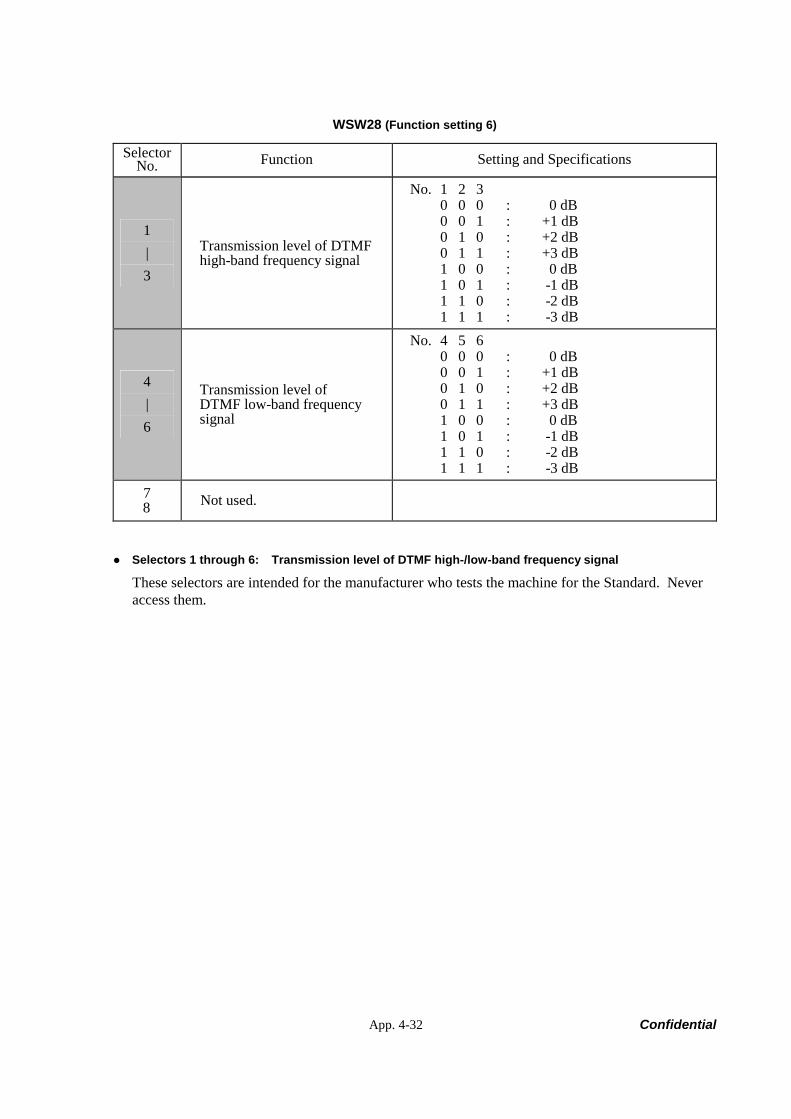
App. 4-32 Confidential
WSW28 (Function setting 6)
Selector No. Function Setting and Specifications
1 | 3
Transmission level of DTMF high-band frequency signal
No. 1 2 3 0 0 0 : 0 dB 0 0 1 : +1 dB 0 1 0 : +2 dB 0 1 1 : +3 dB 1 0 0 : 0 dB 1 0 1 : -1 dB 1 1 0 : -2 dB 1 1 1 : -3 dB
4 | 6
Transmission level of DTMF low-band frequency signal
No. 4 5 6 0 0 0 : 0 dB 0 0 1 : +1 dB 0 1 0 : +2 dB 0 1 1 : +3 dB 1 0 0 : 0 dB 1 0 1 : -1 dB 1 1 0 : -2 dB 1 1 1 : -3 dB
7 8 Not used.
Selectors 1 through 6: Transmission level of DTMF high-/low-band frequency signal
These selectors are intended for the manufacturer who tests the machine for the Standard. Never access them.
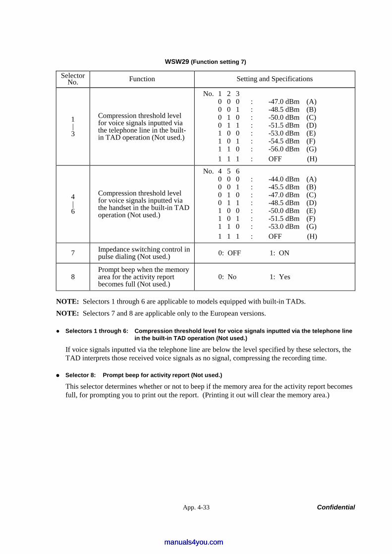
App. 4-33 Confidential
WSW29 (Function setting 7)
Selector No. Function Setting and Specifications
1 | 3
Compression threshold level for voice signals inputted via the telephone line in the built-in TAD operation (Not used.)
No. 1 2 3 0 0 0 : -47.0 dBm (A) 0 0 1 : -48.5 dBm (B) 0 1 0 : -50.0 dBm (C) 0 1 1 : -51.5 dBm (D) 1 0 0 : -53.0 dBm (E) 1 0 1 : -54.5 dBm (F) 1 1 0 : -56.0 dBm (G) 1 1 1 : OFF (H)
4 | 6
Compression threshold level for voice signals inputted via the handset in the built-in TAD operation (Not used.)
No. 4 5 6 0 0 0 : -44.0 dBm (A) 0 0 1 : -45.5 dBm (B) 0 1 0 : -47.0 dBm (C) 0 1 1 : -48.5 dBm (D) 1 0 0 : -50.0 dBm (E) 1 0 1 : -51.5 dBm (F) 1 1 0 : -53.0 dBm (G) 1 1 1 : OFF (H)
7 Impedance switching control in pulse dialing (Not used.) 0: OFF 1: ON
8 Prompt beep when the memory area for the activity report becomes full (Not used.)
0: No 1: Yes
NOTE: Selectors 1 through 6 are applicable to models equipped with built-in TADs. NOTE: Selectors 7 and 8 are applicable only to the European versions.
Selectors 1 through 6: Compression threshold level for voice signals inputted via the telephone line in the built-in TAD operation (Not used.)
If voice signals inputted via the telephone line are below the level specified by these selectors, the TAD interprets those received voice signals as no signal, compressing the recording time.
Selector 8: Prompt beep for activity report (Not used.)
This selector determines whether or not to beep if the memory area for the activity report becomes full, for prompting you to print out the report. (Printing it out will clear the memory area.)
manuals4you.commanuals4you.com
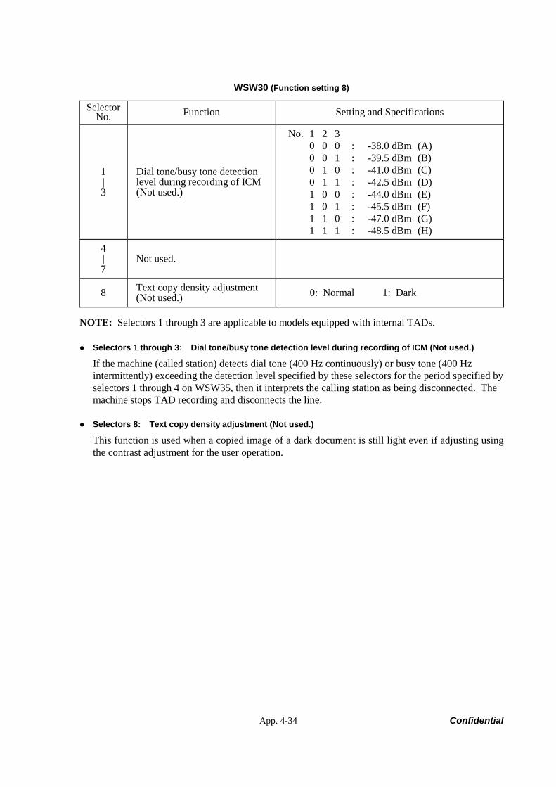
App. 4-34 Confidential
WSW30 (Function setting 8)
Selector No. Function Setting and Specifications
1 | 3
Dial tone/busy tone detection level during recording of ICM (Not used.)
No. 1 2 3 0 0 0 : -38.0 dBm (A) 0 0 1 : -39.5 dBm (B) 0 1 0 : -41.0 dBm (C) 0 1 1 : -42.5 dBm (D) 1 0 0 : -44.0 dBm (E) 1 0 1 : -45.5 dBm (F) 1 1 0 : -47.0 dBm (G) 1 1 1 : -48.5 dBm (H)
4 | 7
Not used.
8 Text copy density adjustment (Not used.) 0: Normal 1: Dark
NOTE: Selectors 1 through 3 are applicable to models equipped with internal TADs.
Selectors 1 through 3: Dial tone/busy tone detection level during recording of ICM (Not used.)
If the machine (called station) detects dial tone (400 Hz continuously) or busy tone (400 Hz intermittently) exceeding the detection level specified by these selectors for the period specified by selectors 1 through 4 on WSW35, then it interprets the calling station as being disconnected. The machine stops TAD recording and disconnects the line.
Selectors 8: Text copy density adjustment (Not used.)
This function is used when a copied image of a dark document is still light even if adjusting using the contrast adjustment for the user operation.
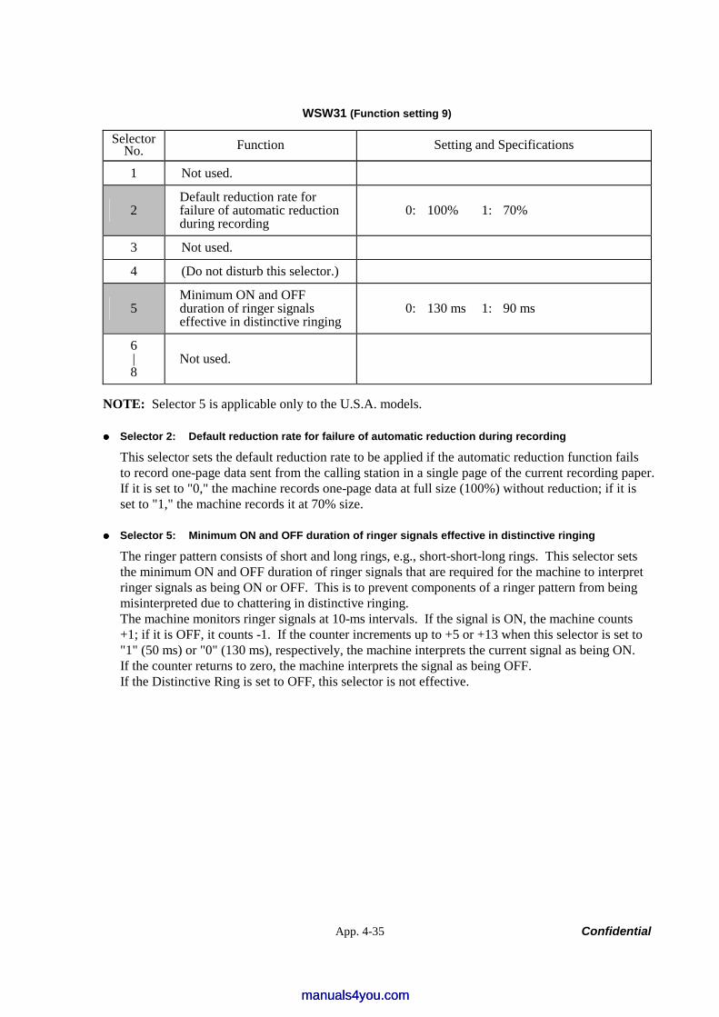
App. 4-35 Confidential
WSW31 (Function setting 9)
Selector No. Function Setting and Specifications
1 Not used.
2 Default reduction rate for failure of automatic reduction during recording
0: 100% 1: 70%
3 Not used.
4 (Do not disturb this selector.)
5 Minimum ON and OFF duration of ringer signals effective in distinctive ringing
0: 130 ms 1: 90 ms
6 | 8
Not used.
NOTE: Selector 5 is applicable only to the U.S.A. models.
Selector 2: Default reduction rate for failure of automatic reduction during recording
This selector sets the default reduction rate to be applied if the automatic reduction function fails to record one-page data sent from the calling station in a single page of the current recording paper. If it is set to "0," the machine records one-page data at full size (100%) without reduction; if it is set to "1," the machine records it at 70% size.
Selector 5: Minimum ON and OFF duration of ringer signals effective in distinctive ringing
The ringer pattern consists of short and long rings, e.g., short-short-long rings. This selector sets the minimum ON and OFF duration of ringer signals that are required for the machine to interpret ringer signals as being ON or OFF. This is to prevent components of a ringer pattern from being misinterpreted due to chattering in distinctive ringing. The machine monitors ringer signals at 10-ms intervals. If the signal is ON, the machine counts +1; if it is OFF, it counts -1. If the counter increments up to +5 or +13 when this selector is set to "1" (50 ms) or "0" (130 ms), respectively, the machine interprets the current signal as being ON. If the counter returns to zero, the machine interprets the signal as being OFF. If the Distinctive Ring is set to OFF, this selector is not effective.
manuals4you.commanuals4you.com
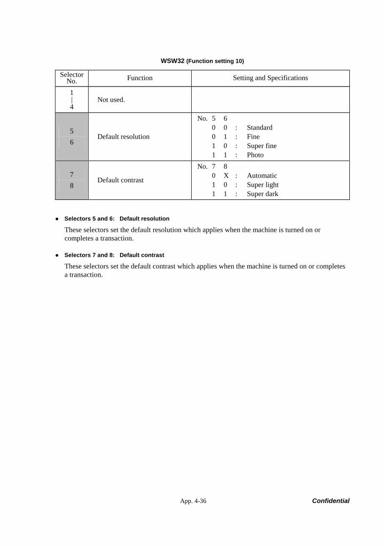
App. 4-36 Confidential
WSW32 (Function setting 10)
Selector No. Function Setting and Specifications
1 | 4
Not used.
5 6
Default resolution
No. 5 6 0 0 : Standard 0 1 : Fine 1 0 : Super fine 1 1 : Photo
7 8
Default contrast
No. 7 8 0 X : Automatic 1 0 : Super light 1 1 : Super dark
Selectors 5 and 6: Default resolution
These selectors set the default resolution which applies when the machine is turned on or completes a transaction.
Selectors 7 and 8: Default contrast
These selectors set the default contrast which applies when the machine is turned on or completes a transaction.
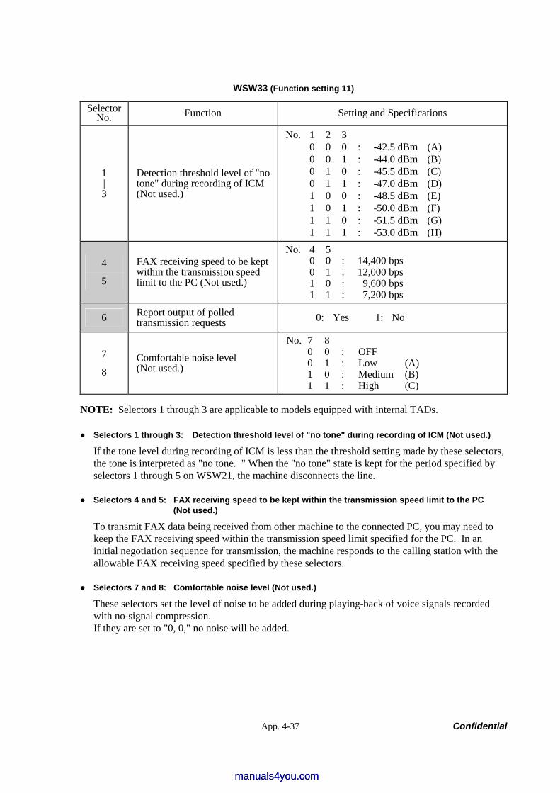
App. 4-37 Confidential
WSW33 (Function setting 11)
Selector No. Function Setting and Specifications
1 | 3
Detection threshold level of "no tone" during recording of ICM (Not used.)
No. 1 2 3 0 0 0 : -42.5 dBm (A) 0 0 1 : -44.0 dBm (B) 0 1 0 : -45.5 dBm (C) 0 1 1 : -47.0 dBm (D) 1 0 0 : -48.5 dBm (E) 1 0 1 : -50.0 dBm (F) 1 1 0 : -51.5 dBm (G) 1 1 1 : -53.0 dBm (H)
4
5
FAX receiving speed to be kept within the transmission speed limit to the PC (Not used.)
No. 4 5 0 0 : 14,400 bps 0 1 : 12,000 bps 1 0 : 9,600 bps 1 1 : 7,200 bps
6 Report output of polled transmission requests 0: Yes 1: No
7
8 Comfortable noise level (Not used.)
No. 7 8 0 0 : OFF 0 1 : Low (A) 1 0 : Medium (B) 1 1 : High (C)
NOTE: Selectors 1 through 3 are applicable to models equipped with internal TADs.
Selectors 1 through 3: Detection threshold level of "no tone" during recording of ICM (Not used.)
If the tone level during recording of ICM is less than the threshold setting made by these selectors, the tone is interpreted as "no tone. " When the "no tone" state is kept for the period specified by selectors 1 through 5 on WSW21, the machine disconnects the line.
Selectors 4 and 5: FAX receiving speed to be kept within the transmission speed limit to the PC (Not used.)
To transmit FAX data being received from other machine to the connected PC, you may need to keep the FAX receiving speed within the transmission speed limit specified for the PC. In an initial negotiation sequence for transmission, the machine responds to the calling station with the allowable FAX receiving speed specified by these selectors.
Selectors 7 and 8: Comfortable noise level (Not used.)
These selectors set the level of noise to be added during playing-back of voice signals recorded with no-signal compression. If they are set to "0, 0," no noise will be added.
manuals4you.commanuals4you.com
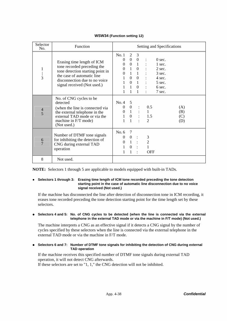
App. 4-38 Confidential
WSW34 (Function setting 12)
Selector No. Function Setting and Specifications
1 | 3
Erasing time length of ICM tone recorded preceding the tone detection starting point in the case of automatic line disconnection due to no voice signal received (Not used.)
No. 1 2 3 0 0 0 : 0 sec. 0 0 1 : 1 sec. 0 1 0 : 2 sec. 0 1 1 : 3 sec. 1 0 0 : 4 sec. 1 0 1 : 5 sec. 1 1 0 : 6 sec. 1 1 1 : 7 sec.
4 5
No. of CNG cycles to be detected (when the line is connected via the external telephone in the external TAD mode or via the machine in F/T mode) (Not used.)
No. 4 5 0 0 : 0.5 (A) 0 1 : 1 (B) 1 0 : 1.5 (C) 1 1 : 2 (D)
6 7
Number of DTMF tone signals for inhibiting the detection of CNG during external TAD operation
No. 6 7 0 0 : 3 0 1 : 2 1 0 : 1 1 1 : OFF
8 Not used.
NOTE: Selectors 1 through 5 are applicable to models equipped with built-in TADs.
Selectors 1 through 3: Erasing time length of ICM tone recorded preceding the tone detection starting point in the case of automatic line disconnection due to no voice signal received (Not used.)
If the machine has disconnected the line after detection of disconnection tone in ICM recording, it erases tone recorded preceding the tone detection starting point for the time length set by these selectors.
Selectors 4 and 5: No. of CNG cycles to be detected (when the line is connected via the external telephone in the external TAD mode or via the machine in F/T mode) (Not used.)
The machine interprets a CNG as an effective signal if it detects a CNG signal by the number of cycles specified by these selectors when the line is connected via the external telephone in the external TAD mode or via the machine in F/T mode.
Selectors 6 and 7: Number of DTMF tone signals for inhibiting the detection of CNG during external TAD operation
If the machine receives this specified number of DTMF tone signals during external TAD operation, it will not detect CNG afterwards. If these selectors are set to "1, 1," the CNG detection will not be inhibited.

App. 4-39 Confidential
WSW35 (Function setting 13)
Selector No. Function Setting and Specifications
1 | 4
Max. detection period of dial tone/busy tone during recording of ICM (Not used.)
No. 1 2 3 4 0 0 0 0 : No detection 0 0 0 1 : 1 sec. 0 0 1 0 : 2 sec. 0 1 0 0 : 4 sec. | | 1 1 1 1 : 15 sec.
5 | 8
Not used.
NOTE: Selectors 1 through 4 are applicable to models equipped with internal TADs.
Selectors 1 through 4: Max. detection period of dial tone/busy tone during recording of ICM (Not used.)
If the machine (called station) detects dial tone or busy tone exceeding the detection level specified by selectors 1 through 3 on WSW30 for the period specified by these selectors, then it disconnects the line.
manuals4you.commanuals4you.com
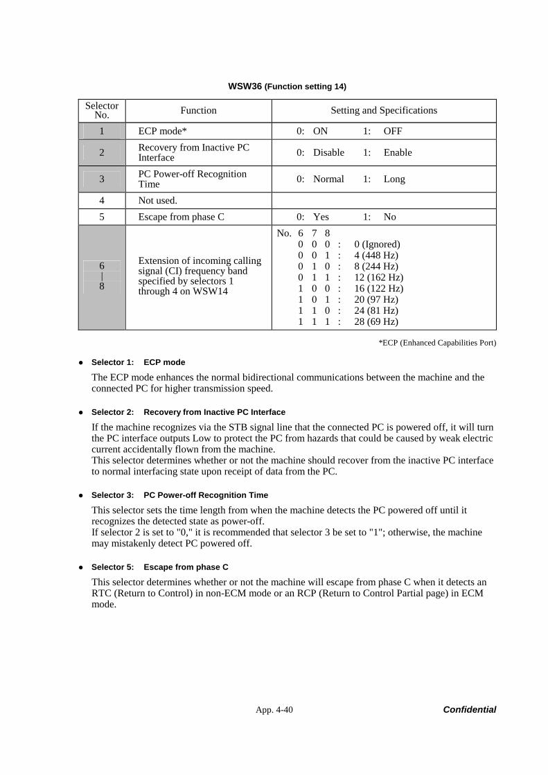
App. 4-40 Confidential
WSW36 (Function setting 14)
Selector No. Function Setting and Specifications
1 ECP mode* 0: ON 1: OFF
2 Recovery from Inactive PC Interface 0: Disable 1: Enable
3 PC Power-off Recognition Time 0: Normal 1: Long
4 Not used. 5 Escape from phase C 0: Yes 1: No
6 | 8
Extension of incoming calling signal (CI) frequency band specified by selectors 1 through 4 on WSW14
No. 6 7 8 0 0 0 : 0 (Ignored) 0 0 1 : 4 (448 Hz) 0 1 0 : 8 (244 Hz) 0 1 1 : 12 (162 Hz) 1 0 0 : 16 (122 Hz) 1 0 1 : 20 (97 Hz) 1 1 0 : 24 (81 Hz) 1 1 1 : 28 (69 Hz)
*ECP (Enhanced Capabilities Port)
Selector 1: ECP mode
The ECP mode enhances the normal bidirectional communications between the machine and the connected PC for higher transmission speed.
Selector 2: Recovery from Inactive PC Interface
If the machine recognizes via the STB signal line that the connected PC is powered off, it will turn the PC interface outputs Low to protect the PC from hazards that could be caused by weak electric current accidentally flown from the machine. This selector determines whether or not the machine should recover from the inactive PC interface to normal interfacing state upon receipt of data from the PC.
Selector 3: PC Power-off Recognition Time
This selector sets the time length from when the machine detects the PC powered off until it recognizes the detected state as power-off. If selector 2 is set to "0," it is recommended that selector 3 be set to "1"; otherwise, the machine may mistakenly detect PC powered off.
Selector 5: Escape from phase C
This selector determines whether or not the machine will escape from phase C when it detects an RTC (Return to Control) in non-ECM mode or an RCP (Return to Control Partial page) in ECM mode.
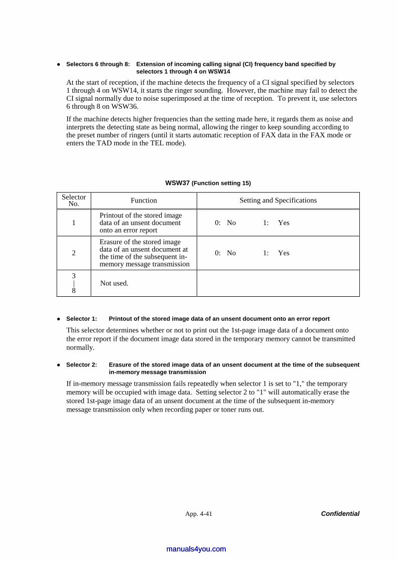
App. 4-41 Confidential
Selectors 6 through 8: Extension of incoming calling signal (CI) frequency band specified by selectors 1 through 4 on WSW14
At the start of reception, if the machine detects the frequency of a CI signal specified by selectors 1 through 4 on WSW14, it starts the ringer sounding. However, the machine may fail to detect the CI signal normally due to noise superimposed at the time of reception. To prevent it, use selectors 6 through 8 on WSW36.
If the machine detects higher frequencies than the setting made here, it regards them as noise and interprets the detecting state as being normal, allowing the ringer to keep sounding according to the preset number of ringers (until it starts automatic reception of FAX data in the FAX mode or enters the TAD mode in the TEL mode).
WSW37 (Function setting 15)
Selector No. Function Setting and Specifications
1 Printout of the stored image data of an unsent document onto an error report
0: No 1: Yes
2 Erasure of the stored image data of an unsent document at the time of the subsequent in-memory message transmission
0: No 1: Yes
3 | 8
Not used.
Selector 1: Printout of the stored image data of an unsent document onto an error report
This selector determines whether or not to print out the 1st-page image data of a document onto the error report if the document image data stored in the temporary memory cannot be transmitted normally.
Selector 2: Erasure of the stored image data of an unsent document at the time of the subsequent in-memory message transmission
If in-memory message transmission fails repeatedly when selector 1 is set to "1," the temporary memory will be occupied with image data. Setting selector 2 to "1" will automatically erase the stored 1st-page image data of an unsent document at the time of the subsequent in-memory message transmission only when recording paper or toner runs out.
manuals4you.commanuals4you.com
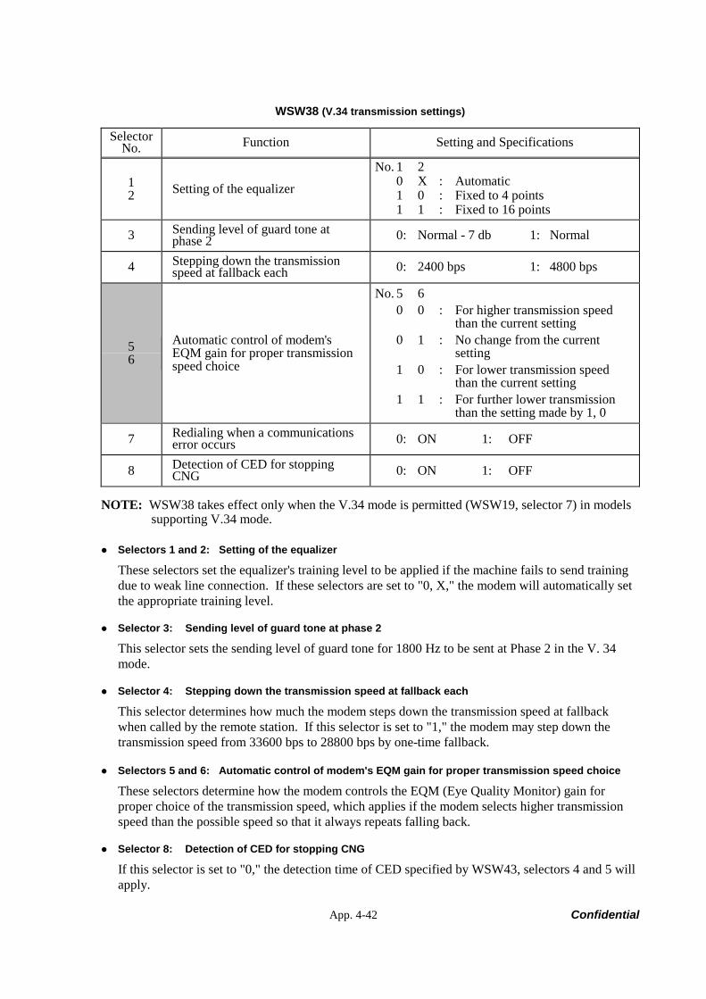
App. 4-42 Confidential
WSW38 (V.34 transmission settings)
Selector No. Function Setting and Specifications
1 2 Setting of the equalizer
No. 1 2 0 X : Automatic 1 0 : Fixed to 4 points 1 1 : Fixed to 16 points
3 Sending level of guard tone at phase 2 0: Normal - 7 db 1: Normal
4 Stepping down the transmission speed at fallback each 0: 2400 bps 1: 4800 bps
5 6
Automatic control of modem's EQM gain for proper transmission speed choice
No. 5 6 0 0 : For higher transmission speed than the current setting 0 1 : No change from the current setting 1 0 : For lower transmission speed than the current setting 1 1 : For further lower transmission than the setting made by 1, 0
7 Redialing when a communications error occurs 0: ON 1: OFF
8 Detection of CED for stopping CNG 0: ON 1: OFF
NOTE: WSW38 takes effect only when the V.34 mode is permitted (WSW19, selector 7) in models supporting V.34 mode.
Selectors 1 and 2: Setting of the equalizer
These selectors set the equalizer's training level to be applied if the machine fails to send training due to weak line connection. If these selectors are set to "0, X," the modem will automatically set the appropriate training level.
Selector 3: Sending level of guard tone at phase 2
This selector sets the sending level of guard tone for 1800 Hz to be sent at Phase 2 in the V. 34 mode.
Selector 4: Stepping down the transmission speed at fallback each
This selector determines how much the modem steps down the transmission speed at fallback when called by the remote station. If this selector is set to "1," the modem may step down the transmission speed from 33600 bps to 28800 bps by one-time fallback.
Selectors 5 and 6: Automatic control of modem's EQM gain for proper transmission speed choice
These selectors determine how the modem controls the EQM (Eye Quality Monitor) gain for proper choice of the transmission speed, which applies if the modem selects higher transmission speed than the possible speed so that it always repeats falling back.
Selector 8: Detection of CED for stopping CNG
If this selector is set to "0," the detection time of CED specified by WSW43, selectors 4 and 5 will apply.
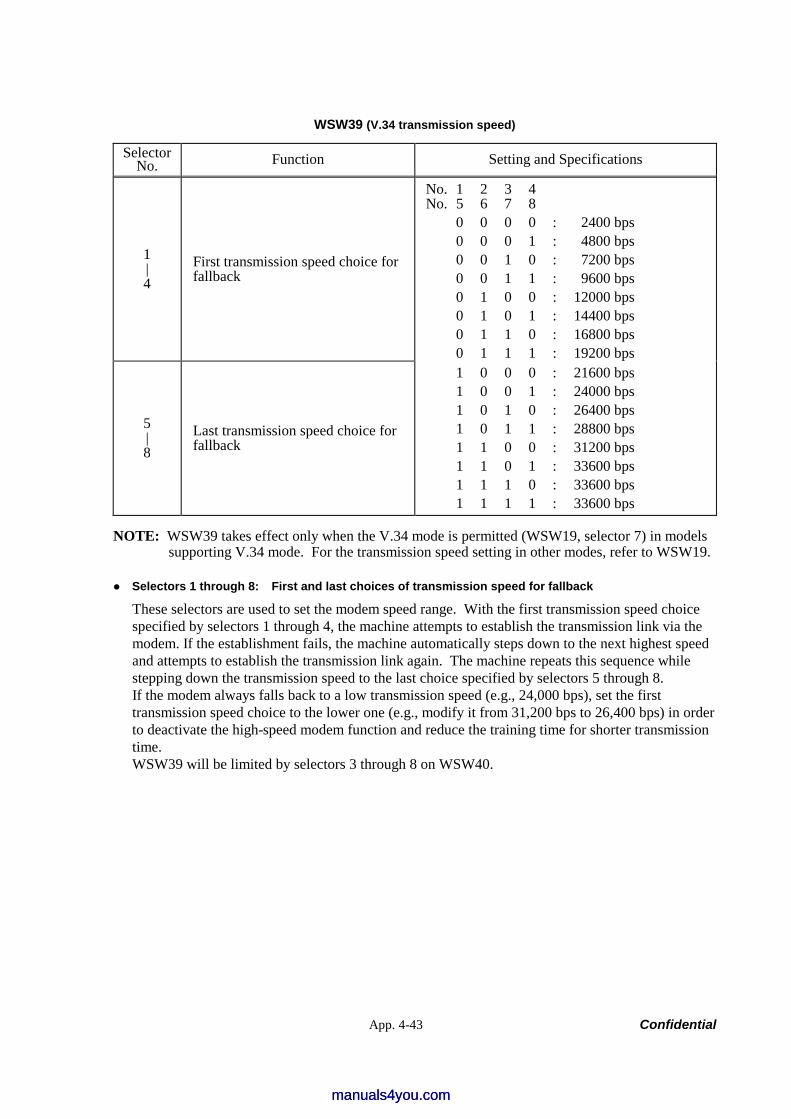
App. 4-43 Confidential
WSW39 (V.34 transmission speed)
Selector No. Function Setting and Specifications
1 | 4
First transmission speed choice for fallback
No. 1 2 3 4 No. 5 6 7 8 0 0 0 0 : 2400 bps 0 0 0 1 : 4800 bps 0 0 1 0 : 7200 bps 0 0 1 1 : 9600 bps 0 1 0 0 : 12000 bps 0 1 0 1 : 14400 bps 0 1 1 0 : 16800 bps 0 1 1 1 : 19200 bps
5 | 8
Last transmission speed choice for fallback
1 0 0 0 : 21600 bps 1 0 0 1 : 24000 bps 1 0 1 0 : 26400 bps 1 0 1 1 : 28800 bps 1 1 0 0 : 31200 bps 1 1 0 1 : 33600 bps 1 1 1 0 : 33600 bps 1 1 1 1 : 33600 bps
NOTE: WSW39 takes effect only when the V.34 mode is permitted (WSW19, selector 7) in models supporting V.34 mode. For the transmission speed setting in other modes, refer to WSW19.
Selectors 1 through 8: First and last choices of transmission speed for fallback
These selectors are used to set the modem speed range. With the first transmission speed choice specified by selectors 1 through 4, the machine attempts to establish the transmission link via the modem. If the establishment fails, the machine automatically steps down to the next highest speed and attempts to establish the transmission link again. The machine repeats this sequence while stepping down the transmission speed to the last choice specified by selectors 5 through 8. If the modem always falls back to a low transmission speed (e.g., 24,000 bps), set the first transmission speed choice to the lower one (e.g., modify it from 31,200 bps to 26,400 bps) in order to deactivate the high-speed modem function and reduce the training time for shorter transmission time. WSW39 will be limited by selectors 3 through 8 on WSW40.
manuals4you.commanuals4you.com
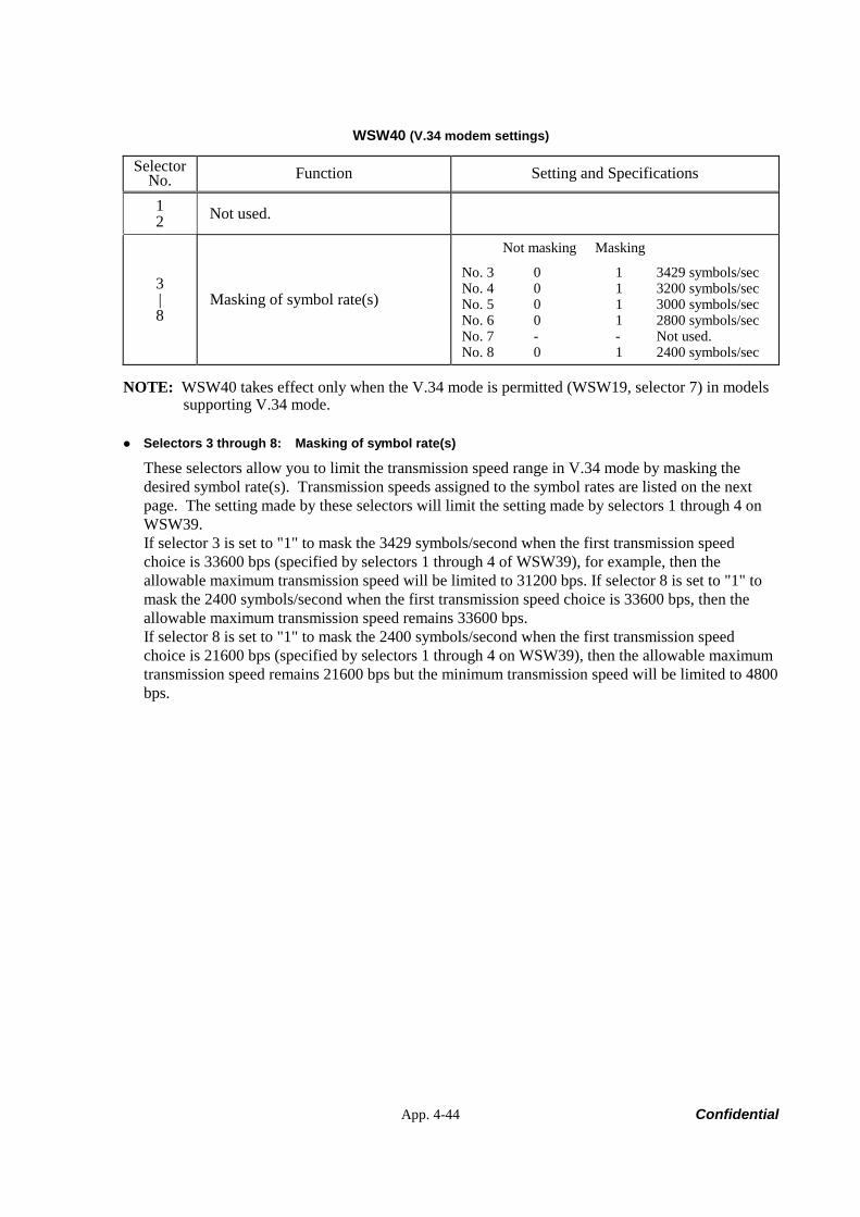
App. 4-44 Confidential
WSW40 (V.34 modem settings)
Selector No. Function Setting and Specifications
1 2 Not used.
3 | 8
Masking of symbol rate(s)
Not masking Masking
No. 3 0 1 3429 symbols/sec No. 4 0 1 3200 symbols/sec No. 5 0 1 3000 symbols/sec No. 6 0 1 2800 symbols/sec No. 7 - - Not used. No. 8 0 1 2400 symbols/sec
NOTE: WSW40 takes effect only when the V.34 mode is permitted (WSW19, selector 7) in models supporting V.34 mode.
Selectors 3 through 8: Masking of symbol rate(s)
These selectors allow you to limit the transmission speed range in V.34 mode by masking the desired symbol rate(s). Transmission speeds assigned to the symbol rates are listed on the next page. The setting made by these selectors will limit the setting made by selectors 1 through 4 on WSW39. If selector 3 is set to "1" to mask the 3429 symbols/second when the first transmission speed choice is 33600 bps (specified by selectors 1 through 4 of WSW39), for example, then the allowable maximum transmission speed will be limited to 31200 bps. If selector 8 is set to "1" to mask the 2400 symbols/second when the first transmission speed choice is 33600 bps, then the allowable maximum transmission speed remains 33600 bps. If selector 8 is set to "1" to mask the 2400 symbols/second when the first transmission speed choice is 21600 bps (specified by selectors 1 through 4 on WSW39), then the allowable maximum transmission speed remains 21600 bps but the minimum transmission speed will be limited to 4800 bps.
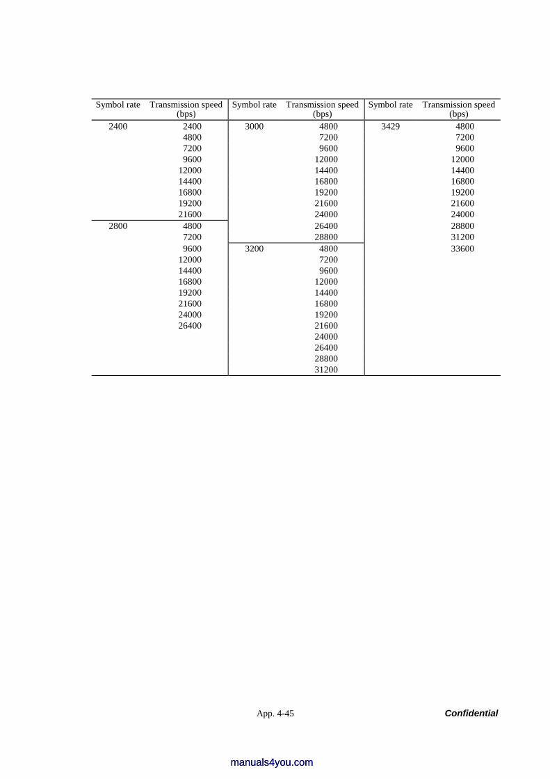
App. 4-45 Confidential
Symbol rate Transmission speed (bps)
Symbol rate Transmission speed (bps)
Symbol rate Transmission speed (bps)
2400 2400 3000 4800 3429 4800 4800 7200 7200 7200 9600 9600 9600 12000 12000 12000 14400 14400 14400 16800 16800 16800 19200 19200 19200 21600 21600 21600 24000 24000
2800 4800 26400 28800 7200 28800 31200 9600 3200 4800 33600 12000 7200 14400 9600 16800 12000 19200 14400 21600 16800 24000 19200 26400 21600 24000 26400 28800 31200
manuals4you.commanuals4you.com
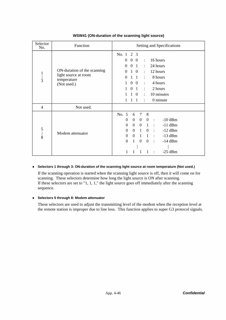
App. 4-46 Confidential
WSW41 (ON-duration of the scanning light source)
Selector No. Function Setting and Specifications
1 | 3
ON-duration of the scanning light source at room temperature (Not used.)
No. 1 2 3 0 0 0 : 16 hours 0 0 1 : 24 hours 0 1 0 : 12 hours 0 1 1 : 8 hours 1 0 0 : 4 hours 1 0 1 : 2 hours 1 1 0 : 10 minutes 1 1 1 : 0 minute
4 Not used.
5 | 8
Modem attenuator
No. 5 6 7 8 0 0 0 0 : -10 dBm 0 0 0 1 : -11 dBm 0 0 1 0 : -12 dBm 0 0 1 1 : -13 dBm 0 1 0 0 : -14 dBm | | 1 1 1 1 : -25 dBm
Selectors 1 through 3: ON-duration of the scanning light source at room temperature (Not used.)
If the scanning operation is started when the scanning light source is off, then it will come on for scanning. These selectors determine how long the light source is ON after scanning. If these selectors are set to "1, 1, 1," the light source goes off immediately after the scanning sequence.
Selectors 5 through 8: Modem attenuator
These selectors are used to adjust the transmitting level of the modem when the reception level at the remote station is improper due to line loss. This function applies to super G3 protocol signals.
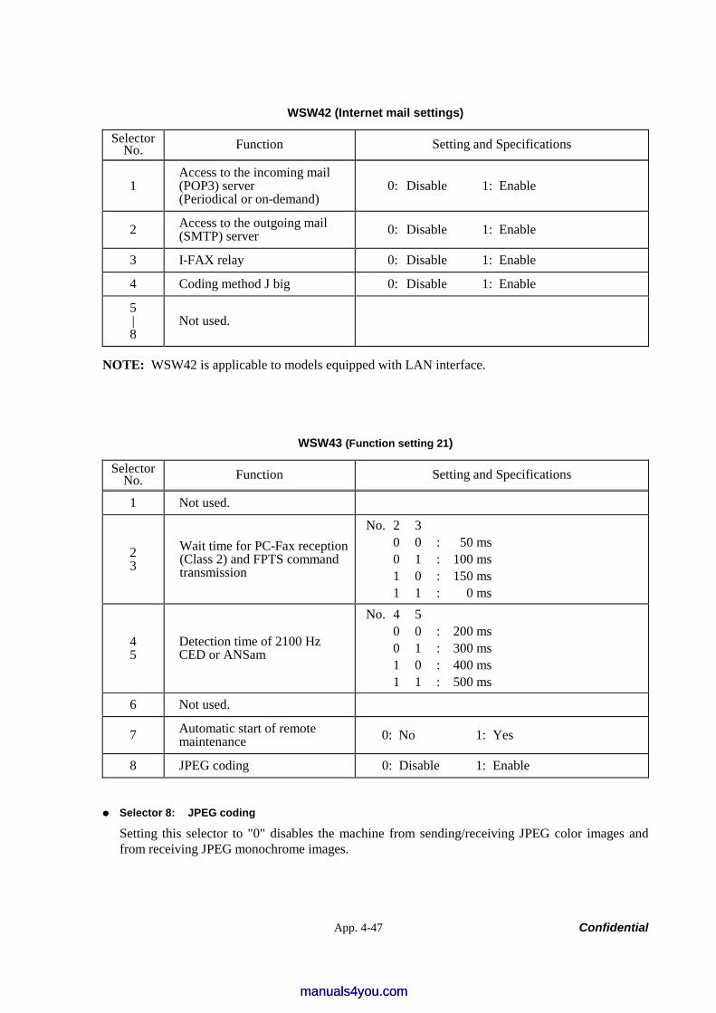
App. 4-47 Confidential
WSW42 (Internet mail settings)
Selector No. Function Setting and Specifications
1 Access to the incoming mail (POP3) server (Periodical or on-demand)
0: Disable 1: Enable
2 Access to the outgoing mail (SMTP) server 0: Disable 1: Enable
3 I-FAX relay 0: Disable 1: Enable
4 Coding method J big 0: Disable 1: Enable
5 | 8
Not used.
NOTE: WSW42 is applicable to models equipped with LAN interface.
WSW43 (Function setting 21)
Selector No. Function Setting and Specifications
1 Not used.
2 3
Wait time for PC-Fax reception (Class 2) and FPTS command transmission
No. 2 3 0 0 : 50 ms 0 1 : 100 ms 1 0 : 150 ms 1 1 : 0 ms
4 5
Detection time of 2100 Hz CED or ANSam
No. 4 5 0 0 : 200 ms 0 1 : 300 ms 1 0 : 400 ms 1 1 : 500 ms
6 Not used.
7 Automatic start of remote maintenance 0: No 1: Yes
8 JPEG coding 0: Disable 1: Enable
Selector 8: JPEG coding
Setting this selector to "0" disables the machine from sending/receiving JPEG color images and from receiving JPEG monochrome images.
manuals4you.commanuals4you.com
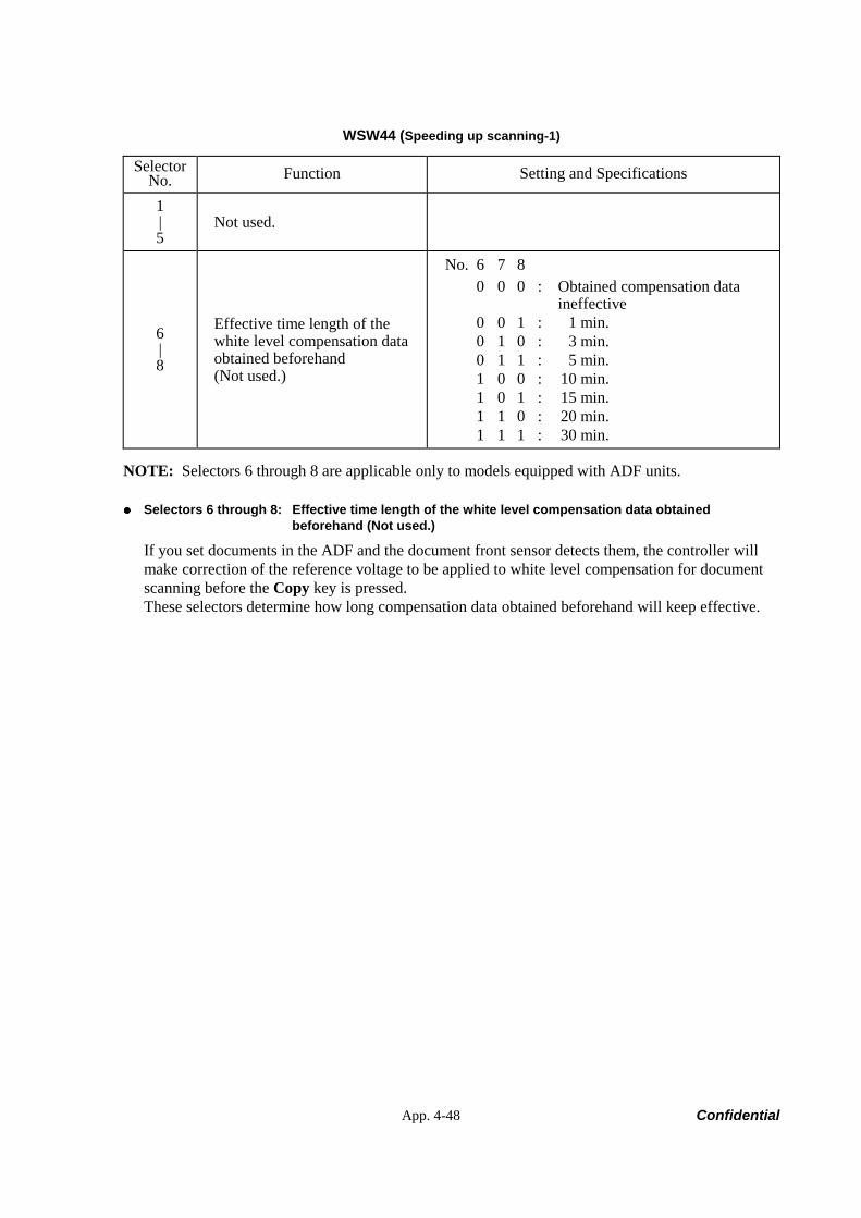
App. 4-48 Confidential
WSW44 (Speeding up scanning-1)
Selector No. Function Setting and Specifications
1 | 5
Not used.
6 | 8
Effective time length of the white level compensation data obtained beforehand (Not used.)
No. 6 7 8 0 0 0 : Obtained compensation data
ineffective 0 0 1 : 1 min. 0 1 0 : 3 min. 0 1 1 : 5 min. 1 0 0 : 10 min. 1 0 1 : 15 min. 1 1 0 : 20 min. 1 1 1 : 30 min.
NOTE: Selectors 6 through 8 are applicable only to models equipped with ADF units.
Selectors 6 through 8: Effective time length of the white level compensation data obtained beforehand (Not used.)
If you set documents in the ADF and the document front sensor detects them, the controller will make correction of the reference voltage to be applied to white level compensation for document scanning before the Copy key is pressed. These selectors determine how long compensation data obtained beforehand will keep effective.
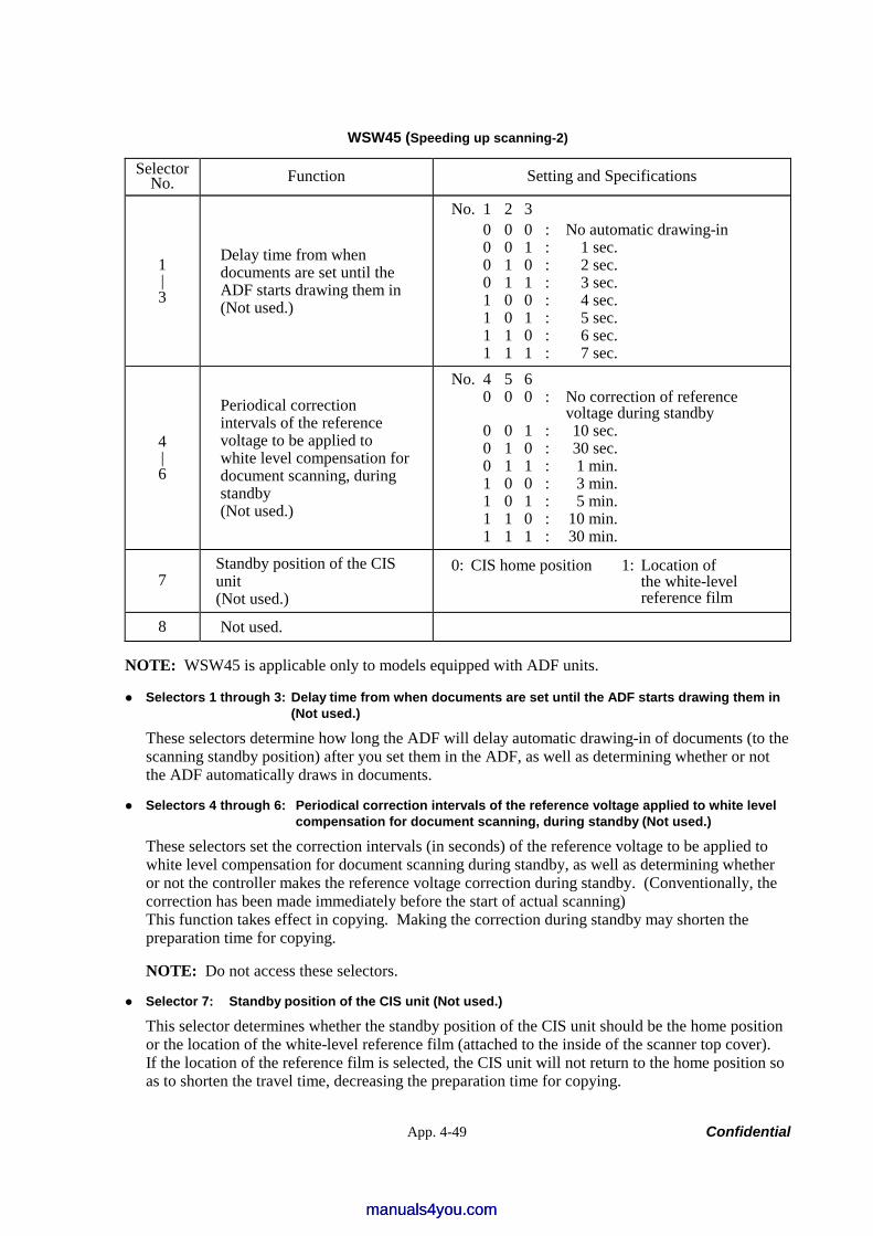
App. 4-49 Confidential
WSW45 (Speeding up scanning-2)
Selector No. Function Setting and Specifications
1 | 3
Delay time from when documents are set until the ADF starts drawing them in (Not used.)
No. 1 2 3 0 0 0 : No automatic drawing-in 0 0 1 : 1 sec. 0 1 0 : 2 sec. 0 1 1 : 3 sec. 1 0 0 : 4 sec. 1 0 1 : 5 sec. 1 1 0 : 6 sec. 1 1 1 : 7 sec.
4 | 6
Periodical correction intervals of the reference voltage to be applied to white level compensation for document scanning, during standby (Not used.)
No. 4 5 6 0 0 0 : No correction of reference
voltage during standby 0 0 1 : 10 sec. 0 1 0 : 30 sec. 0 1 1 : 1 min. 1 0 0 : 3 min. 1 0 1 : 5 min. 1 1 0 : 10 min. 1 1 1 : 30 min.
7 Standby position of the CIS unit (Not used.)
0: CIS home position 1: Location of the white-level reference film
8 Not used.
NOTE: WSW45 is applicable only to models equipped with ADF units.
Selectors 1 through 3: Delay time from when documents are set until the ADF starts drawing them in (Not used.)
These selectors determine how long the ADF will delay automatic drawing-in of documents (to the scanning standby position) after you set them in the ADF, as well as determining whether or not the ADF automatically draws in documents.
Selectors 4 through 6: Periodical correction intervals of the reference voltage applied to white level compensation for document scanning, during standby (Not used.)
These selectors set the correction intervals (in seconds) of the reference voltage to be applied to white level compensation for document scanning during standby, as well as determining whether or not the controller makes the reference voltage correction during standby. (Conventionally, the correction has been made immediately before the start of actual scanning) This function takes effect in copying. Making the correction during standby may shorten the preparation time for copying.
NOTE: Do not access these selectors.
Selector 7: Standby position of the CIS unit (Not used.)
This selector determines whether the standby position of the CIS unit should be the home position or the location of the white-level reference film (attached to the inside of the scanner top cover). If the location of the reference film is selected, the CIS unit will not return to the home position so as to shorten the travel time, decreasing the preparation time for copying.
manuals4you.commanuals4you.com
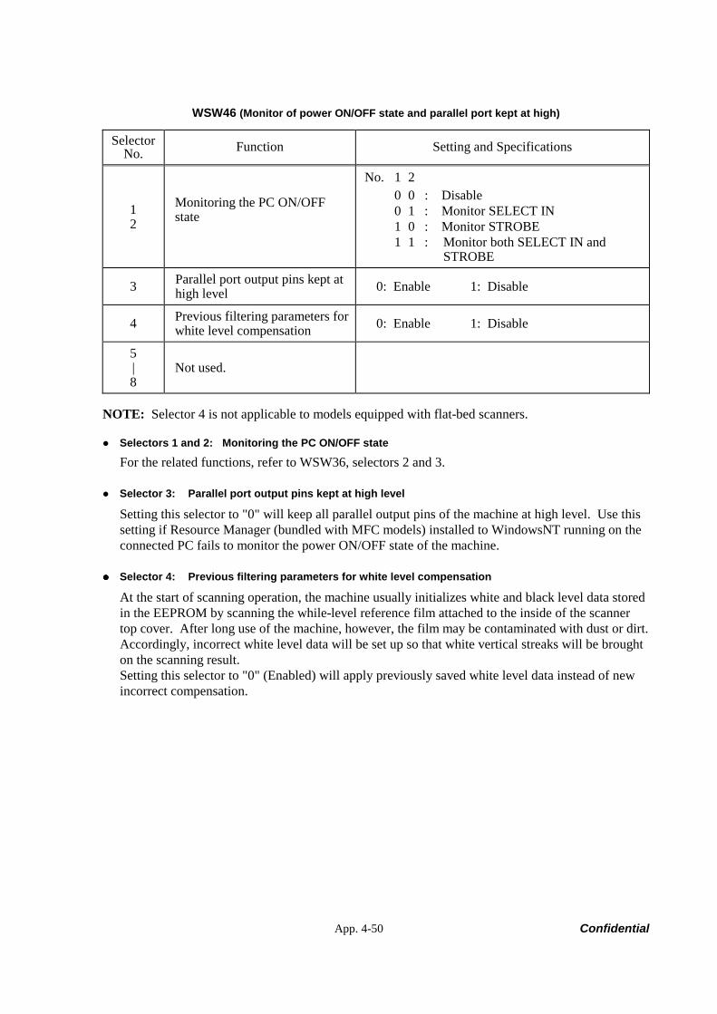
App. 4-50 Confidential
WSW46 (Monitor of power ON/OFF state and parallel port kept at high)
Selector No. Function Setting and Specifications
1 2
Monitoring the PC ON/OFF state
No. 1 2 0 0 : Disable 0 1 : Monitor SELECT IN 1 0 : Monitor STROBE 1 1 : Monitor both SELECT IN and
STROBE
3 Parallel port output pins kept at high level 0: Enable 1: Disable
4 Previous filtering parameters for white level compensation 0: Enable 1: Disable
5 | 8
Not used.
NOTE: Selector 4 is not applicable to models equipped with flat-bed scanners.
Selectors 1 and 2: Monitoring the PC ON/OFF state
For the related functions, refer to WSW36, selectors 2 and 3.
Selector 3: Parallel port output pins kept at high level
Setting this selector to "0" will keep all parallel output pins of the machine at high level. Use this setting if Resource Manager (bundled with MFC models) installed to WindowsNT running on the connected PC fails to monitor the power ON/OFF state of the machine.
Selector 4: Previous filtering parameters for white level compensation
At the start of scanning operation, the machine usually initializes white and black level data stored in the EEPROM by scanning the while-level reference film attached to the inside of the scanner top cover. After long use of the machine, however, the film may be contaminated with dust or dirt. Accordingly, incorrect white level data will be set up so that white vertical streaks will be brought on the scanning result. Setting this selector to "0" (Enabled) will apply previously saved white level data instead of new incorrect compensation.
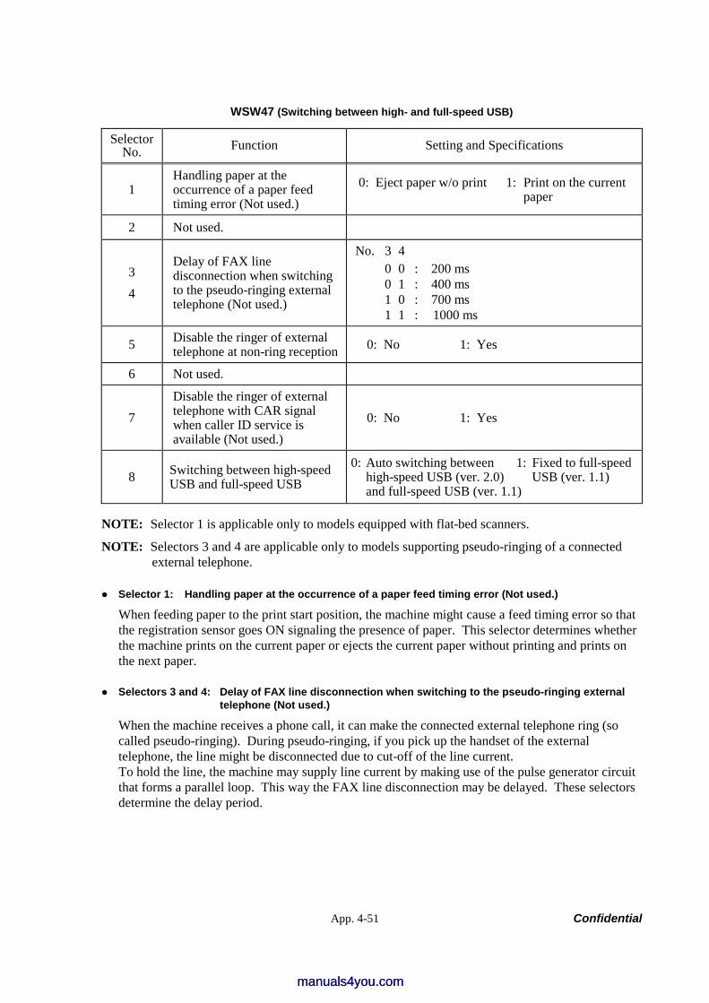
App. 4-51 Confidential
WSW47 (Switching between high- and full-speed USB)
Selector No. Function Setting and Specifications
1 Handling paper at the occurrence of a paper feed timing error (Not used.)
0: Eject paper w/o print 1: Print on the current paper
2 Not used.
3 4
Delay of FAX line disconnection when switching to the pseudo-ringing external telephone (Not used.)
No. 3 4 0 0 : 200 ms 0 1 : 400 ms 1 0 : 700 ms 1 1 : 1000 ms
5 Disable the ringer of external telephone at non-ring reception 0: No 1: Yes
6 Not used.
7 Disable the ringer of external telephone with CAR signal when caller ID service is available (Not used.)
0: No 1: Yes
8 Switching between high-speed USB and full-speed USB
0: Auto switching between 1: Fixed to full-speed high-speed USB (ver. 2.0) USB (ver. 1.1) and full-speed USB (ver. 1.1)
NOTE: Selector 1 is applicable only to models equipped with flat-bed scanners.
NOTE: Selectors 3 and 4 are applicable only to models supporting pseudo-ringing of a connected external telephone.
Selector 1: Handling paper at the occurrence of a paper feed timing error (Not used.)
When feeding paper to the print start position, the machine might cause a feed timing error so that the registration sensor goes ON signaling the presence of paper. This selector determines whether the machine prints on the current paper or ejects the current paper without printing and prints on the next paper.
Selectors 3 and 4: Delay of FAX line disconnection when switching to the pseudo-ringing external telephone (Not used.)
When the machine receives a phone call, it can make the connected external telephone ring (so called pseudo-ringing). During pseudo-ringing, if you pick up the handset of the external telephone, the line might be disconnected due to cut-off of the line current. To hold the line, the machine may supply line current by making use of the pulse generator circuit that forms a parallel loop. This way the FAX line disconnection may be delayed. These selectors determine the delay period.
manuals4you.commanuals4you.com
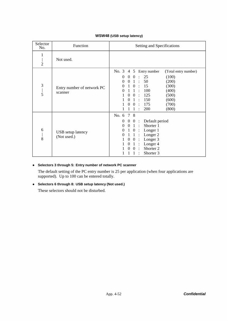
App. 4-52 Confidential
WSW48 (USB setup latency)
Selector No. Function Setting and Specifications
1 | 2
Not used.
3 | 5
Entry number of network PC scanner
No. 3 4 5 Entry number (Total entry number) 0 0 0 : 25 (100) 0 0 1 : 50 (200) 0 1 0 : 15 (300) 0 1 1 : 100 (400) 1 0 0 : 125 (500) 1 0 1 : 150 (600) 1 0 0 : 175 (700) 1 1 1 : 200 (800)
6 | 8
USB setup latency (Not used.)
No. 6 7 8 0 0 0 : Default period 0 0 1 : Shorter 1 0 1 0 : Longer 1 0 1 1 : Longer 2 1 0 0 : Longer 3 1 0 1 : Longer 4 1 0 0 : Shorter 2 1 1 1 : Shorter 3
Selectors 3 through 5: Entry number of network PC scanner
The default setting of the PC entry number is 25 per application (when four applications are supported). Up to 100 can be entered totally.
Selectors 6 through 8: USB setup latency (Not used.)
These selectors should not be disturbed.
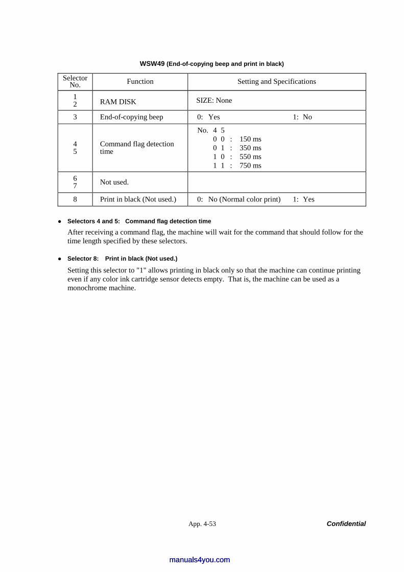
App. 4-53 Confidential
WSW49 (End-of-copying beep and print in black)
Selector No. Function Setting and Specifications
1 2 RAM DISK SIZE: None
3 End-of-copying beep 0: Yes 1: No
4 5
Command flag detection time
No. 4 5 0 0 : 150 ms 0 1 : 350 ms 1 0 : 550 ms 1 1 : 750 ms
6 7 Not used.
8 Print in black (Not used.) 0: No (Normal color print) 1: Yes
Selectors 4 and 5: Command flag detection time
After receiving a command flag, the machine will wait for the command that should follow for the time length specified by these selectors.
Selector 8: Print in black (Not used.)
Setting this selector to "1" allows printing in black only so that the machine can continue printing even if any color ink cartridge sensor detects empty. That is, the machine can be used as a monochrome machine.
manuals4you.commanuals4you.com
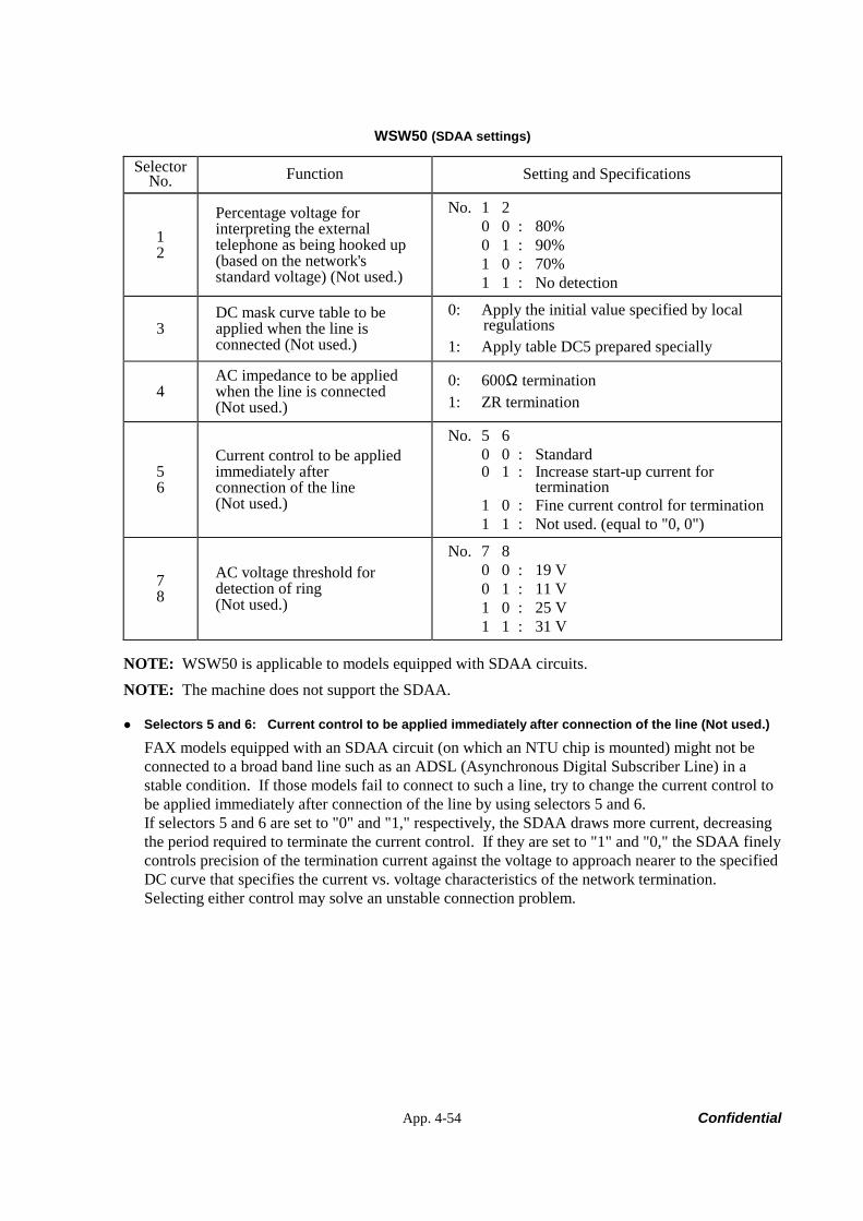
App. 4-54 Confidential
WSW50 (SDAA settings)
Selector No. Function Setting and Specifications
1 2
Percentage voltage for interpreting the external telephone as being hooked up (based on the network's standard voltage) (Not used.)
No. 1 2 0 0 : 80% 0 1 : 90% 1 0 : 70% 1 1 : No detection
3 DC mask curve table to be applied when the line is connected (Not used.)
0: Apply the initial value specified by local regulations
1: Apply table DC5 prepared specially
4 AC impedance to be applied when the line is connected (Not used.)
0: 600Ω termination 1: ZR termination
5 6
Current control to be applied immediately after connection of the line (Not used.)
No. 5 6 0 0 : Standard 0 1 : Increase start-up current for
termination 1 0 : Fine current control for termination 1 1 : Not used. (equal to "0, 0")
7 8
AC voltage threshold for detection of ring (Not used.)
No. 7 8 0 0 : 19 V 0 1 : 11 V 1 0 : 25 V 1 1 : 31 V
NOTE: WSW50 is applicable to models equipped with SDAA circuits. NOTE: The machine does not support the SDAA.
Selectors 5 and 6: Current control to be applied immediately after connection of the line (Not used.)
FAX models equipped with an SDAA circuit (on which an NTU chip is mounted) might not be connected to a broad band line such as an ADSL (Asynchronous Digital Subscriber Line) in a stable condition. If those models fail to connect to such a line, try to change the current control to be applied immediately after connection of the line by using selectors 5 and 6. If selectors 5 and 6 are set to "0" and "1," respectively, the SDAA draws more current, decreasing the period required to terminate the current control. If they are set to "1" and "0," the SDAA finely controls precision of the termination current against the voltage to approach nearer to the specified DC curve that specifies the current vs. voltage characteristics of the network termination. Selecting either control may solve an unstable connection problem.

App. 4-55 Confidential
WSW51 (Function setting 16)
Selector No. Function Setting and Specifications
1 Output of communications error report when transmission verification report is disabled
0: Enable 1: Disable
2 | 8
Not used.
manuals4you.commanuals4you.com

Confidential
FAX2820/2920 MFC7220/7225N
APPENDIX 5. WIRING DIAGRAM
This appendix provides the wiring diagram that helps you understand the connections between PCBs.
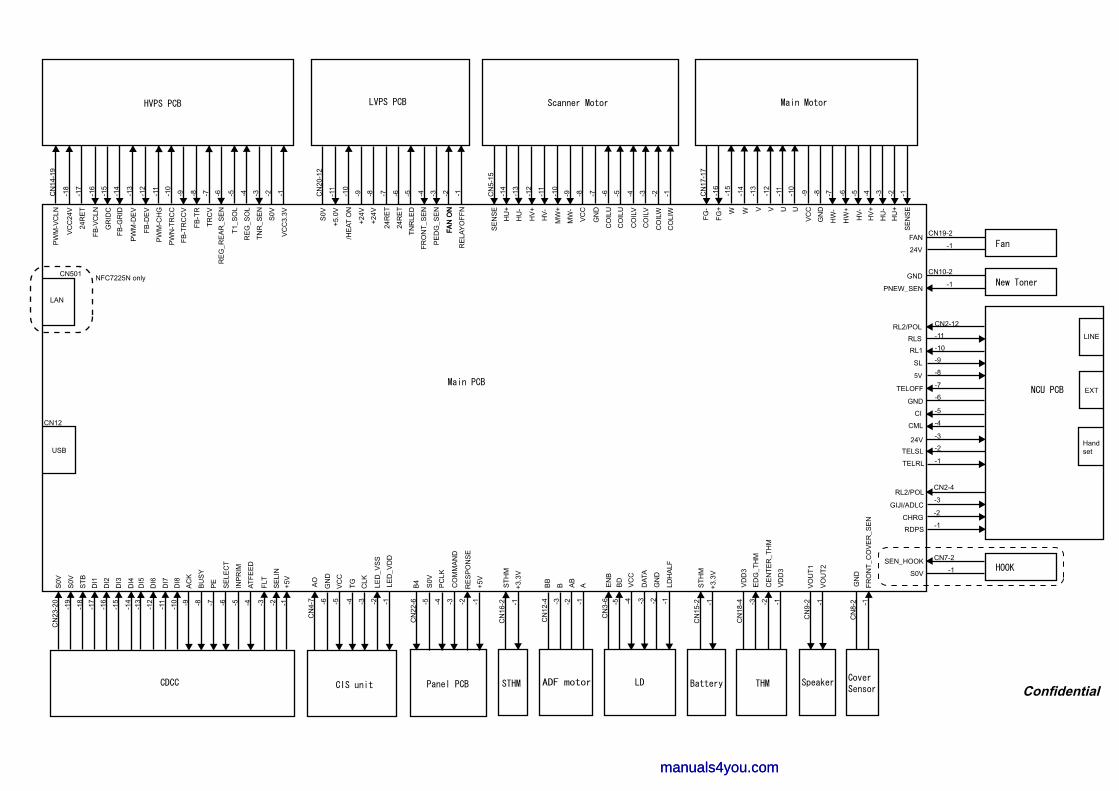
LAN
CN501
RL2/POL CN2-12
-7
-10RLS
-5
-4
-3
-2
-1
SL
GND
TELOFF
CI
24V
TELRL
CML
TELSL
CN
9-2 -1
VO
UT
2
VO
UT
1
LINE
EXT
RL1
-6
5V -8
INP
RIM
AT
FE
ED
FLT
SE
LIN
CLK
TG LE
D_V
DD
VC
C
GN
D
LED
_VS
S
AO
CN
4-7
-11
-10 -9 -6 -5 -4 -3 -2 -1
AC
K
-3 -2-4-15
BU
SY
PE
SE
LEC
T
USB
CN12
RE
SP
ON
SE
CO
MM
AN
D
S0V
PC
LK
+5V
-5 -4 -3 -2 -1
CN
22-6
VC
C24
V
24R
ET
PW
M-D
EV
TR
CV
T1_
SO
L
RE
G_R
EA
R_S
EN
RE
G_S
OL
TN
R_S
EN
S0V
-18
-11
-10
-9 -8 -7 -6 -5 -4 -3 -2 -1-16
-15
-14
-13
-12
FB
-VC
LN
GR
IDC
FB
-GR
ID
FB
-DE
V
PW
M-C
HG
PW
N-T
RC
C
FB
-TR
CC
V
FB
-TR
-11
-10
-9 -8 -7 -6 -5 -4 -3 -2
+24V
FAN
ON
CN
20-1
2S
0V
+5.0
V
/HE
AT
ON
24R
ET
TN
RLE
D
PE
DG
_SE
N
+24V
24R
ET
FR
ON
T_S
EN
-11
-10
-9 -8 -7 -6 -5 -4 -3 -2 -1CN
5-15
-14
-13
-12
ST
HM
-1
CN
16-2
S0V
S0V
ST
B
+5V
-7 -6 -5 -2 -1
-16
-11
-9
BD
VC
C
DA
TA
GN
D
LDH
ALF
-4 -3 -2 -1
B4
+3.3
V
CN
12-4 -3
BB
B AB
A ST
HM
-1
CN
15-2
+3.3
V
-17
VC
C3.
3V
CN
14-1
9P
WM
-VC
LN
SE
NS
E
HU
+
HU
-
HV
+
HV
-
FAN
ON
MW
-
MW
+
VC
C
GN
D
CO
ILU
CO
ILU
CO
ILV
CO
ILV
CO
ILW
CO
LIW
-11
-10
-9 -8 -7 -6 -5 -4 -3 -2 -1CN
17-1
7
-14
-13
-12
SE
NS
E
HU
+
HU
-
HV
+
HV
-
HW
-
HW
+
VC
C
GN
DU UVVW W
-15
-16
FG
+
FG
-
CN19-2
-124V
FAN
CN10-2
-1PNEW_SEN
GND
CN
8-2 -1
FR
ON
T_C
OV
ER
_SE
N
GN
D
CE
NT
ER
_TH
M-1-2
VD
D3
Handset
NFC7225N only
-1R
ELA
YO
FF
N
VD
D3
-3
CN
18-4
ED
G_T
HM
CN2-4
-3
-2
-1
GIJI/ADLC
RL2/POL
CHRG
RDPS
EN
B-5
CN
3-6
-14 -8-17
-13
-12 -1
CN
23-2
0
-18
-19
DI8
DI7
DI6
DI5
DI4
DI3
DI2
DI1
CN7-2
-1S0V
SEN_HOOK
Confidential
manuals4you.commanuals4you.com

Confidential
FAX2820/2920 MFC7220/7225N
APPENDIX 6. CIRCUIT DIAGRAMS
This appendix provides the circuit diagrams of the NCU PCB and power supply PCB.
A. NCU PCB (U.S.A. and CANADA models) NCU PCB (EUROPE models)
B. Power Supply PCB 100V (U.S.A. and CANADA models) Power Supply PCB 200V (EUROPE models)
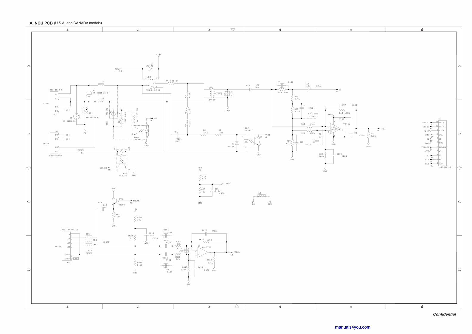
+
+
-
+
+
+
-
+
D
666666654321
63 62 651 66664
C
B
A
C
B
A
D
R274.7k
C16
C4706.3V
+5V
REF
C4 C103
GND
U1BA10358
6
57
GND
6B
TELSL
@C17C104
@R2124k
@C14
C471
@R15 150k
REF
R233.3k
GND
@C15C104
C7C104
C5C2.250V
@C9 C221
@C10 C471
@R8 620
@R192.7k
@R17150k
GND
R16 100k6B
RL1
@R13
3.3k
R25620
REF
GND
R18620
@C18C221
GND
@R242.7k
@C6C10
+5V
C8C104
R28100k
R14 100k
R102.7k
C19C222
U1BA10358
4
2
31
8
@C12C101
GND
@R9150
REF
R12 100k
@R2224k
D71SS120
PH2TLP320
AK1
AK2
EC
@C3 C150V
@PH1PS2533-1
A
K
E
C
D31SS120
R7 100 2W
GND
D5
RA-242M-C6
R6
6.2k@D1
ERA15-04
D4RA-351M-V6-2
@D2
S1ZB60
A1
-A2
+
@R1
120
2W
R224kFG
6BCI
GND
+24V
R5
6.2k
C1
C474250V
PH3TLP421
A
K
E
C
@T1
BT-27
GND
R4
6.2k
6BSL
R114.3k
5ASL
GND
2CTELRL
2ACML
2BPLS
5BRL1
+24V3D
TELSL
2CTELOFF
4BCI
+5V
@J3
285D-D440J-111
1XX
2XX
3XX
4XX
5GND
6GND
+5V
@Q1
C5395
C
B
E
6BTELOFF
6BCML
GND
6BTELRL
@R20100
@C13
C470
10V
GND
+5V
GNDFG
6CPLS
J2
R41-4910-A
3XX
4XX
7FG
8FG
J1
R41-4910-A
3XX
4XX
7FG
8FG
NC
NC
NC
NC
C11
C101
L8
L1
L3
L2
@L4
@L7
@L6
@L5
C2
C102
P1
1-292161-1
1 PLS
2 RL1
3 SL
4 +5V
5 TELOFF
6 GND
7 CI
8 CML
9 +24V
10 TELSL
11 TELRL
NC
SW1
A5X-24E-908
1
2
1211
7
R324k
D6
RA-242M-C6C102
C104
C103C104
C104C104
C101
C104
(LINE)
(EXT)
(H.S)
+
manuals4you.commanuals4you.com
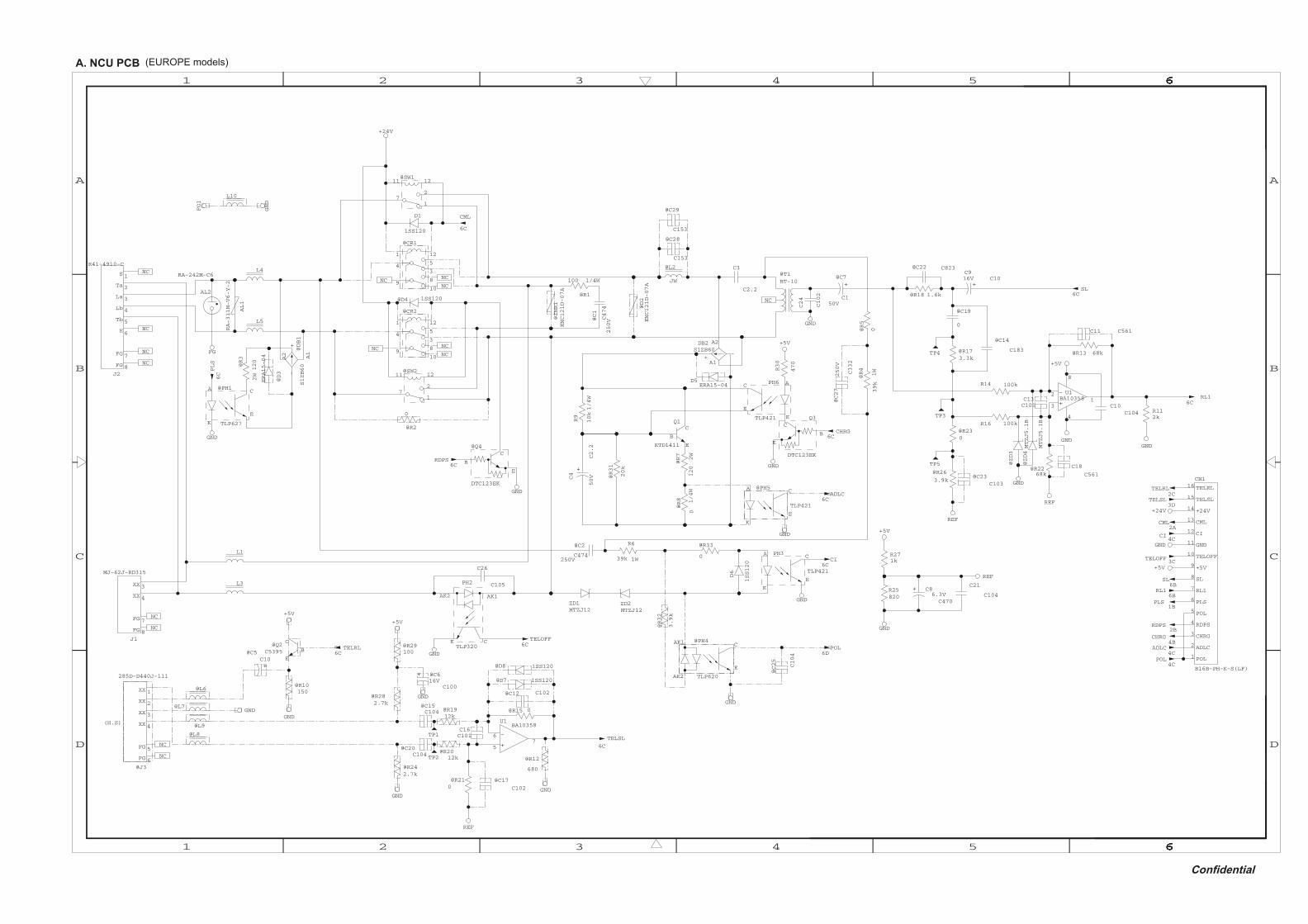
+
+
-
+
+
+
+
+
-
D
666666654321
63 62 651 66664
C
B
A
C
B
A
D
@R3
120
2W
@D3
ERA15-04
@C2
C474250V
R6
39k 1WPH3
TLP421
A
K
E
C
PH2
TLP320CE
AK2 AK1
D1
1SS120
D6
1SS120
@PH1
TLP627
A
K
E
C
@R31
20k
C4
C2.2
50V
ZD2MTZJ12
ZD1MTZJ12
@R7
120
2W
@R8
01/4W
@ZNR1
ENC121D-07AAL2
RA-242M-C6
@DB1
S1ZB60
A1
-A2
+
@Q4
DTC123EK
C
B
E
PH6
TLP421
A
K
E
C
DB2S1ZB60
A1
-
A2
+
D5ERA15-04
@C7
C150V
6CPLS
6CCI
6CTELOFF
6C
CML
FG1
GND
GND
GND
FG
GND
GND
GND
+24V
6CRDPS
R9
10k1/4W
Q1
KTD1411
C
B
E
@CR1
9
1 12
10
8
43
5
@D4 1SS120
@CR2
9
1 12
10
8
43
5
C24
C102
@PH5
TLP421
A
K
E
C
GND
6CADLC
@C29
C153
@C28
C153
@SW2
1
2
1211
7
@SW1
1
2
1211
7
@R2
0
J1
MJ-62J-RD315
3XX
4XX
7FG
8FG
J2
R41-4910-C
1S
2Ta
3La
4Lb
5Tb
6E
7FG
8FG
@T1BT-10
NC
NC
NC
NC
NC
NC
GND
@R173.3k
@R13 68k
R112k
@R18 1.6k 6CSL
R14 100k
U1BA10358
4
2
31
8
C18
C561
R16 100k
GND
C10C104
+5V
C11 C561
@C22 C823
6CRL1
REF
C9C1016V
@C14
C183
@R2268k
4CCI
GND
6BRL1
3CTELOFF
+24V
+5V
2CTELRL
2ACML
6BSL
3DTELSL
1BPLS
4BCHRG
2BRDPS
R25820
C8
C4706.3V
GND
R271k
+5V
REF
C13C101
GND
@C5C10
6C
TELSL
@C12 [email protected]
@D7 1SS120
@C20C104
@R210
@D8 1SS120
@R15 0
NC
@R10150
GND
REF
@C6
C10016V
NC
@C17
C102
GND
6CTELRL @R29
100
GND
U1BA10358
6
57
C16C101
@R242.7k
@R2012k
@C15C104
@Q2C5395
C
B
E
@J3
285D-D440J-111
1XX
2XX
3XX
4XX
5FG
6FG
@R1912k
GND
@R12
680
+5V
+5V
+5V
R30
470
6CCHRG
GND
Q3
DTC123EK
C
B
E
4CADLC
C3
C2.2
L10
L4
L5
L1
@L6
@L7
@L9
@L8
REF
@R26
3.9k@C23
C103 GND
@ZD3
MTZJ5.1B
@ZD4
MTZJ5.1B
C21
C104
@D2
ENC121D-07A
@R4
39k
1W
TP2
TP1
TP3
NC
TP4
@R230
@C19
0
TP5
C26
C105
AL1
RA-311M-V6-Y-2
@L2
JW
@C27
C332
250V
@R5
0NC
NC
NC
NCNC
NC
@R1
100 1/4W
@C1
C474
250V
@R33
0
@R32
3.9k
@PH4
TLP620
AK1
AK2
E
C
GND
@C25
C104
CN1
B16B-PH-K-S(LF)
1 POL
2 ADLC
3 CHRG
4 RDPS
5 POL
6 PLS
7 RL1
8 SL
9 +5V
10 TELOFF
11 GND
12 CI
13 CML
14 +24V
15 TELSL
16 TELRL
4CPOL
6DPOL
L3
(H.S)
+
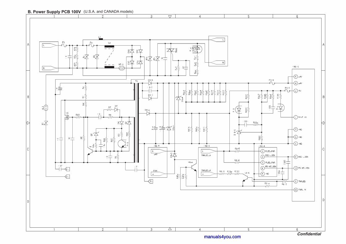
manuals4you.commanuals4you.com
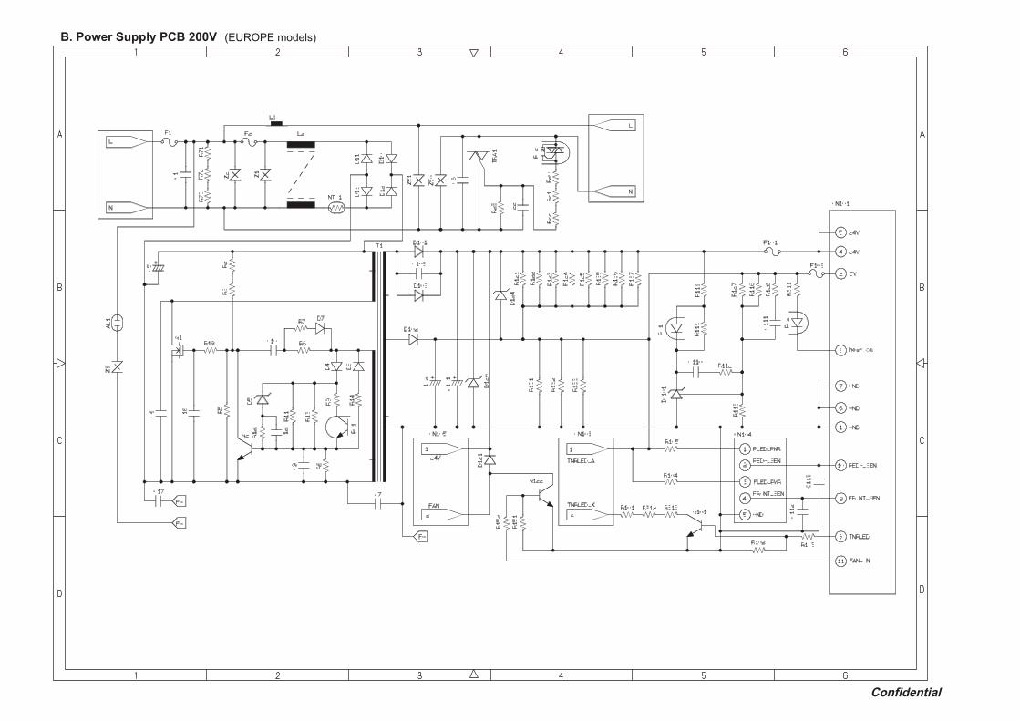

February '05 SM-FAX037(1) 8X5A01 Printed in Japan
manuals4you.commanuals4you.com

FACSIMILE EQUIPMENT PARTS REFERENCE LIST MODEL: MFC7220 / 7225N
FAX2820 / 2920 (For U.S.A / Canada / Brazil)

© Copyright Brother 2005 All rights reserved No part of this publication may be reproduced in any form or by any means without permission in writing from the publisher. Specifications are subject to change without prior notice.
manuals4you.commanuals4you.com
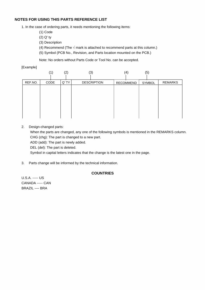
NOTES FOR USING THIS PARTS REFERENCE LIST 1. In the case of ordering parts, it needs mentioning the following items:
(1) Code (2) Q' ty (3) Description (4) Recommend (The √ mark is attached to recommend parts at this column.) (5) Symbol (PCB No., Revision, and Parts location mounted on the PCB.)
Note: No orders without Parts Code or Tool No. can be accepted.
[Example] (1) (2) (3) (4) (5)
REF.NO. CODE Q' TY DESCRIPTION RECOMMEND SYMBOL REMARKS
2. Design-changed parts:
When the parts are changed, any one of the following symbols is mentioned in the REMARKS column. CHG (chg): The part is changed to a new part. ADD (add): The part is newly added. DEL (del): The part is deleted. Symbol in capital letters indicates that the change is the latest one in the page.
3. Parts change will be informed by the technical information.
COUNTRIES U.S.A. ----- US CANADA ----- CAN BRAZIL ---- BRA
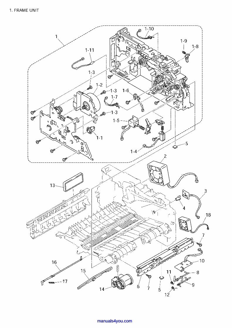
manuals4you.commanuals4you.com
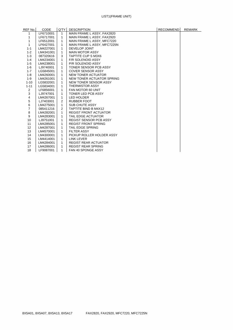
LIST1(FRAME UNIT)
REF No. CODE Q'TY DESCRIPTION RECOMMEND REMARK1 LF6710001 1 MAIN FRAME L ASSY, FAX28201 LF6717001 1 MAIN FRAME L ASSY, FAX29201 LF6512001 1 MAIN FRAME L ASSY, MFC72201 LF6427001 1 MAIN FRAME L ASSY, MFC7225N
1-1 LM4227001 1 DEVELOP JOINT1-2 LM4341001 1 MAIN MOTOR ASSY1-3 087320616 3 TAPTITE CUP S M3X61-4 LM4234001 1 F/R SOLENOID ASSY1-5 LM4238001 1 P/R SOLENOID ASSY1-6 LJ9740001 1 TONER SENSOR PCB ASSY1-7 LG5845001 1 COVER SENSOR ASSY1-8 LM4260001 1 NEW TONER ACTUATOR1-9 LM4261001 1 NEW TONER ACTUATOR SPRING1-10 LG5832001 1 NEW TONER SENSOR ASSY1-11 LG5834001 1 THERMISTOR ASSY
2 LF6856001 1 FAN MOTOR 60 UNIT3 LJ9747001 1 TONER LED PCB ASSY 4 LM4267001 1 LED HOLDER5 LJ7403001 2 RUBBER FOOT6 LM4275001 1 SUB CHUTE ASSY7 085411216 2 TAPTITE BIND B M4X128 LM4282001 1 REGIST FRONT ACTUATOR9 LM4283001 1 TAIL EDGE ACTUATOR
10 LJ9751001 1 REGIST SENSOR PCB ASSY11 LM4285001 1 REGIST FRONT SPRING12 LM4287001 1 TAIL EDGE SPRING13 LM4570001 1 FILTER ASSY14 LM4300001 1 PICKUP ROLLER HOLDER ASSY15 LM4414001 1 LINK LEVER16 LM4284001 1 REGIST REAR ACTUATOR17 LM4286001 1 REGIST REAR SPRING18 LF9087001 1 FAN 40 SPONGE ASSY
FAX2820, FAX2920, MFC7220, MFC7225N 8X5A01, 8X5A07, 8X5A13, 8X5A17
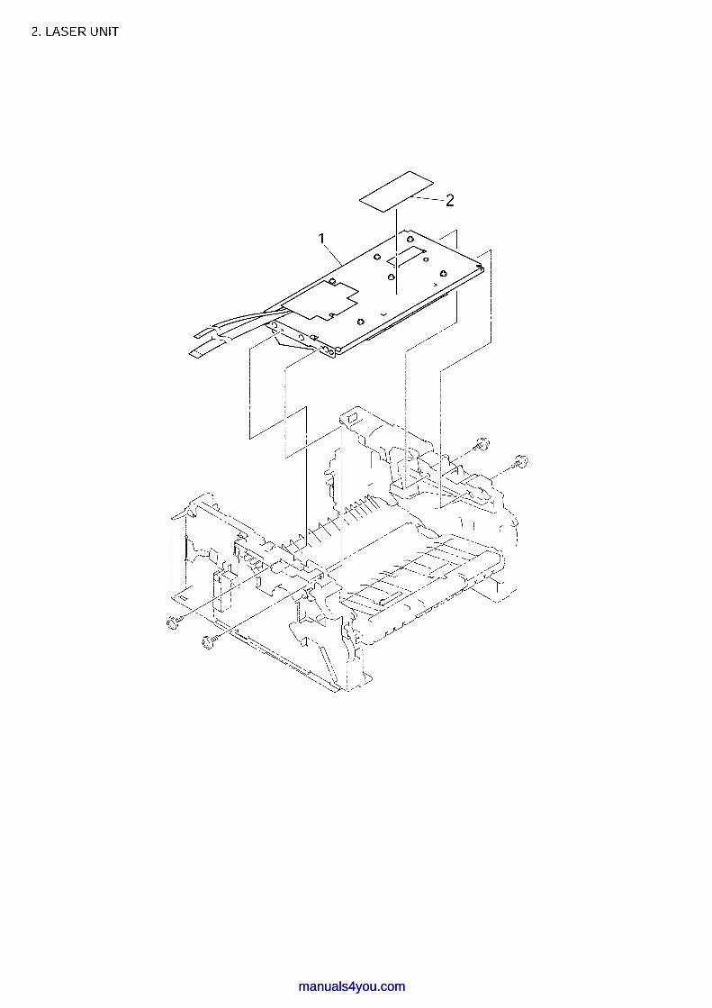
manuals4you.commanuals4you.com

LIST2(LASER UNIT)
REF No. CODE Q'TY DESCRIPTION RECOMMEND REMARK1 LM4578001 1 LASER UNIT(SP)2 LJ0908001 1 LASER CAUTION LABEL
FAX2820, FAX2920, MFC7220, MFC7225N 8X5A01, 8X5A07, 8X5A13, 8X5A17
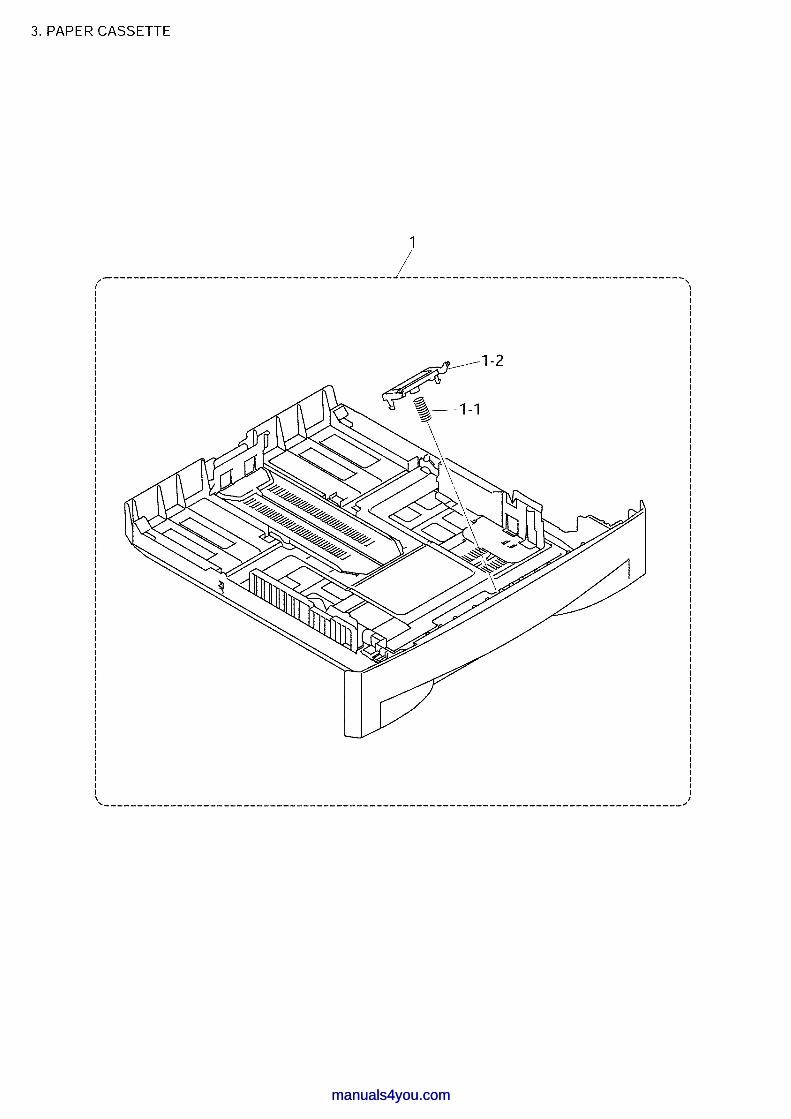
manuals4you.commanuals4you.com

LIST3(PAPER CASSETTE)
REF No. CODE Q'TY DESCRIPTION RECOMMEND REMARK1 LM4131003 1 PAPER TRAY ASSY, GRAY(1737), FAX2820/FAX29201 LM4131001 1 PAPER TRAY ASSY, GRAY(1581), MFC7220/MFC7225N
1-1 LM4146001 1 SEPARATION PAD SPRING1-2 LM4143001 1 SEPARATION PAD HOLDER ASSY
FAX2820, FAX2920, MFC7220, MFC7225N 8X5A01, 8X5A07, 8X5A13, 8X5A17
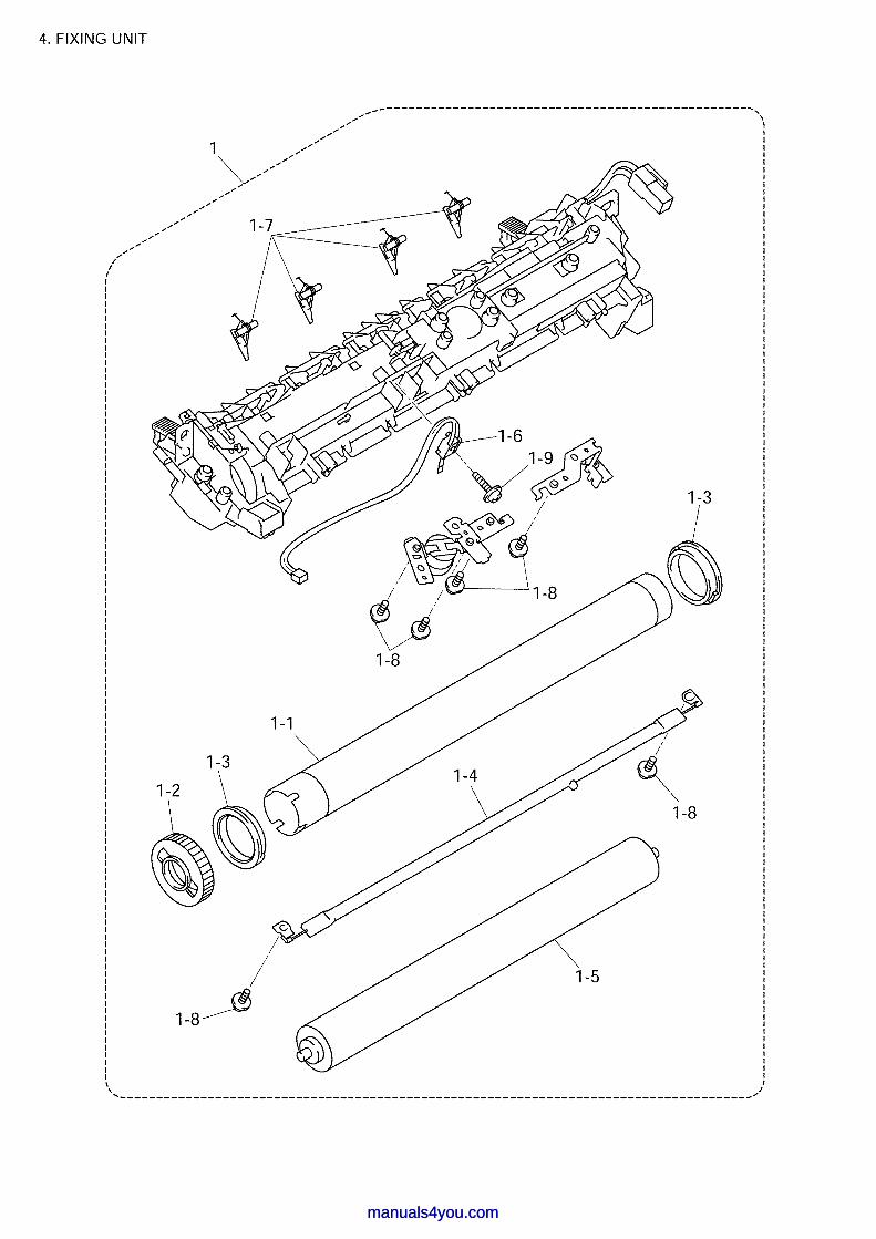
manuals4you.commanuals4you.com

LIST4(FIXING UNIT)
REF No. CODE Q'TY DESCRIPTION RECOMMEND REMARK1 LM4573001 1 FUSER UNIT(SP)
1-1 LM4009001 1 HEAT ROLLER1-2 LM4010001 1 HR GEAR1-3 LM4011001 2 HR BUSH1-4 LM4012001 1 HALOGEN HEATER 115V 1-5 LM4013001 1 PRESSURE ROLLER1-6 LM4018001 1 THERMISTOR ASSY1-7 LM4342001 4 SEPARATE CLAW ASSY1-8 LM3855001 6 SCREW, PAN (S/P WASHER) M3X81-9 087311216 1 TAPTITE CUP B M3X12
FAX2820, FAX2920, MFC7220, MFC7225N 8X5A01, 8X5A07, 8X5A13, 8X5A17
manuals4you.com
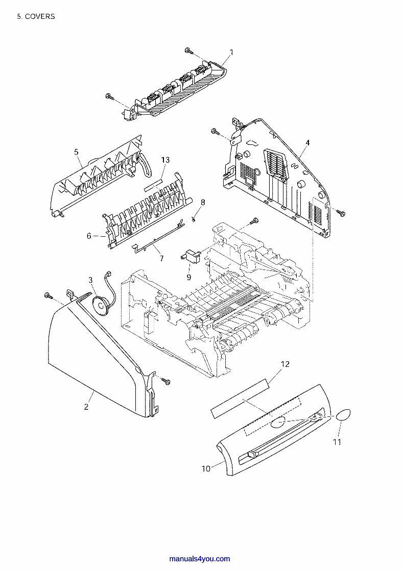
manuals4you.commanuals4you.com

LIST5(COVERS)
REF No. CODE Q'TY DESCRIPTION RECOMMEND REMARK1 LM4113001 1 INNER CHUTE, GRAY(1581)2 LF6434001 1 SIDE COVER L, GRAY(1736)3 LG6047001 1 SPEAKER ASSY 4 LF9089001 1 SIDE COVER R ASSY, GRAY(1736)5 LM4120001 1 REAR COVER, GRAY(1736)6 LM4122001 1 REAR CHUTE COVER7 LM4123001 1 PAPER EJECT ACTUATOR8 LJ5066001 1 EJECT ACTUATOR SPRING9 LM4568001 1 REAR COVER STOPPER
10 LM4124003 1 FRONT COVER ASSY, GRAY(1737), FAX2820/FAX292010 LM4124001 1 FRONT COVER ASSY, GRAY(1581), MFC7220/MFC7225N11 LM4162001 1 BROTHER EMBLEM12 LM4165001 1 PROCESS UNIT OP LABEL13 LM4167001 1 HEATER CAUTION LABEL
FAX2820, FAX2920, MFC7220, MFC7225N 8X5A01, 8X5A07, 8X5A13, 8X5A17
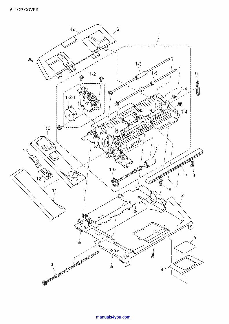
manuals4you.commanuals4you.com

LIST6(TOP COVER)
REF No. CODE Q'TY DESCRIPTION RECOMMEND SYMBOL REMARK1 LF6439002 1 DOCUMENT CHUTE ASSY, GRAY(1737),
FAX2820/FAX29201 LF6439001 1 DOCUMENT CHUTE ASSY, GRAY(1581),
MFC7220/MFC7225N1-1 UF5511001 1 SEPARATION ROLLER1-2 LF6442001 1 SCANNING DRIVE ASSY
1-2-1 LF6446001 1 SCANNING MOTOR F SUB ASSY1-3 LF6449001 1 LF ROLLER1-4 LF9115001 2 LF ROLLER COLLAR1-5 LF6452001 1 EJECTION ROLLER ASSY1-6 LF6455001 1 LF ROLLER GEAR2 LF6458002 1 INNER CHUTE COVER ASSY, GRAY(1737),
FAX2820/FAX29202 LF6458001 1 INNER CHUTE COVER ASSY, GRAY(1581),
MFC7220/MFC7225N
3 LM4105001 1 EJECT ROLLER ASSY4 LF6462002 1 PAPER STOPPER L, GRAY(1737), FAX2820/FAX29204 LF6462001 1 PAPER STOPPER L, GRAY(1581),
MFC7220/MFC7225N5 LF6463002 1 PAPER STOPPER S, GRAY(1737), FAX2820/FAX29205 LF6463001 1 PAPER STOPPER S, GRAY(1581),
MFC7220/MFC7225N
6 LF6469001 1 DOCUMENT BASE ASSY, GRAY(1736)7 LG5584001 1 CIS √8 UU2028001 2 CIS SPRING9 LF6465001 1 LINK STOPPER
10 LF6466002 1 HANDSET HOLDER, GRAY(1737), FAX2820/FAX292010 LF6466001 1 HANDSET HOLDER, GRAY(1581), MFC7220/MFC7225N11 ---- NOT USED12 LG6052001 1 HOOK PCB ASSY B53K80313 UF8167008 1 ACTUATOR HOOK, GRAY(1495), FAX2820/FAX292013 UF8167009 1 ACTUATOR HOOK, GRAY(1581), MFC7220/MFC7225N
FAX2820, FAX2920, MFC7220, MFC7225N 8X5A01, 8X5A07, 8X5A13, 8X5A17
manuals4you.com
manuals4you.com
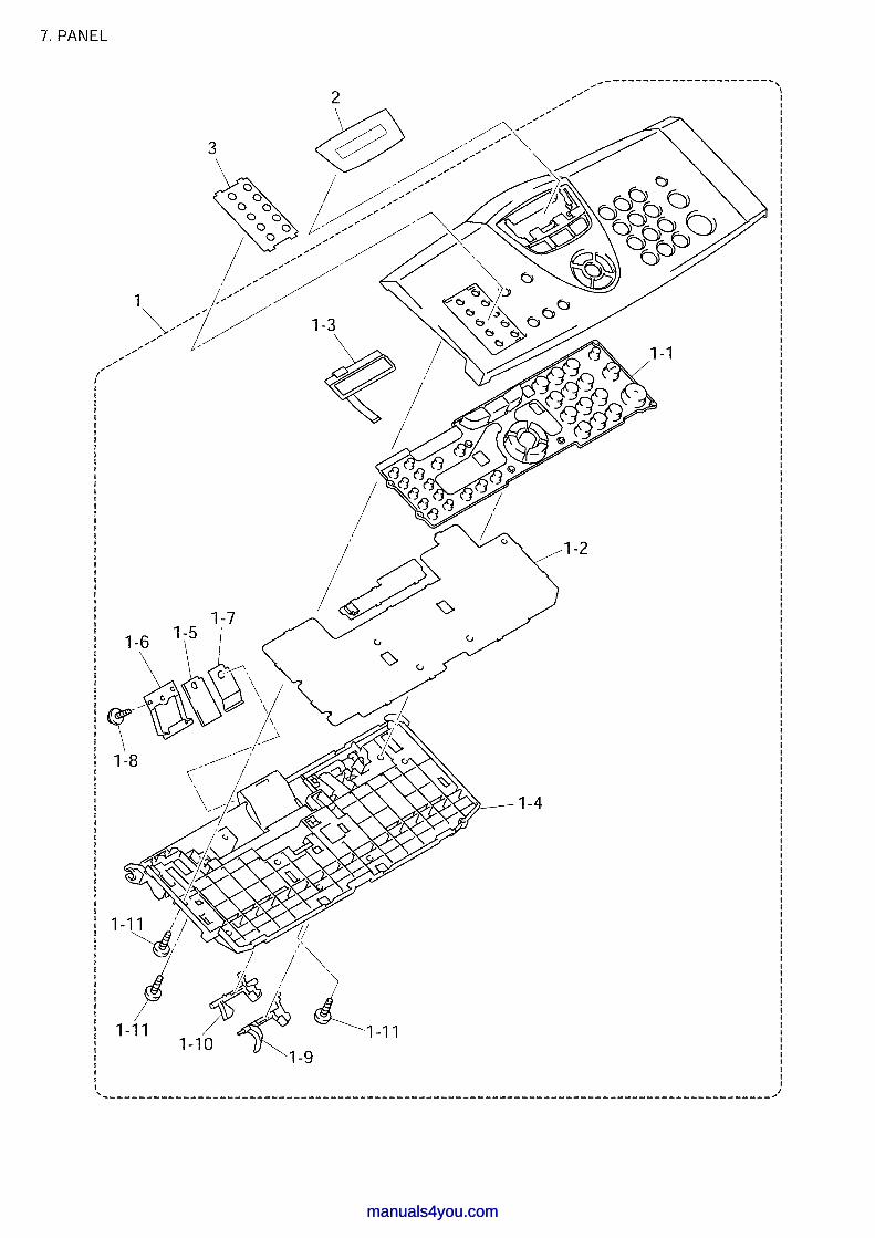
manuals4you.commanuals4you.com
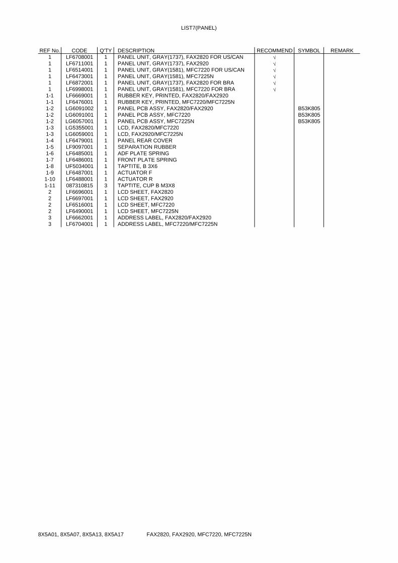
LIST7(PANEL)
REF No. CODE Q'TY DESCRIPTION RECOMMEND SYMBOL REMARK1 LF6708001 1 PANEL UNIT, GRAY(1737), FAX2820 FOR US/CAN √1 LF6711001 1 PANEL UNIT, GRAY(1737), FAX2920 √1 LF6514001 1 PANEL UNIT, GRAY(1581), MFC7220 FOR US/CAN √1 LF6473001 1 PANEL UNIT, GRAY(1581), MFC7225N √1 LF6872001 1 PANEL UNIT, GRAY(1737), FAX2820 FOR BRA √1 LF6998001 1 PANEL UNIT, GRAY(1581), MFC7220 FOR BRA √
1-1 LF6669001 1 RUBBER KEY, PRINTED, FAX2820/FAX29201-1 LF6476001 1 RUBBER KEY, PRINTED, MFC7220/MFC7225N1-2 LG6091002 1 PANEL PCB ASSY, FAX2820/FAX2920 B53K8051-2 LG6091001 1 PANEL PCB ASSY, MFC7220 B53K8051-2 LG6057001 1 PANEL PCB ASSY, MFC7225N B53K8051-3 LG5355001 1 LCD, FAX2820/MFC72201-3 LG6059001 1 LCD, FAX2920/MFC7225N1-4 LF6479001 1 PANEL REAR COVER1-5 LF9097001 1 SEPARATION RUBBER1-6 LF6485001 1 ADF PLATE SPRING1-7 LF6486001 1 FRONT PLATE SPRING1-8 UF5034001 1 TAPTITE, B 3X61-9 LF6487001 1 ACTUATOR F1-10 LF6488001 1 ACTUATOR R1-11 087310815 3 TAPTITE, CUP B M3X8
2 LF6696001 1 LCD SHEET, FAX28202 LF6697001 1 LCD SHEET, FAX29202 LF6516001 1 LCD SHEET, MFC72202 LF6490001 1 LCD SHEET, MFC7225N3 LF6662001 1 ADDRESS LABEL, FAX2820/FAX29203 LF6704001 1 ADDRESS LABEL, MFC7220/MFC7225N
FAX2820, FAX2920, MFC7220, MFC7225N 8X5A01, 8X5A07, 8X5A13, 8X5A17
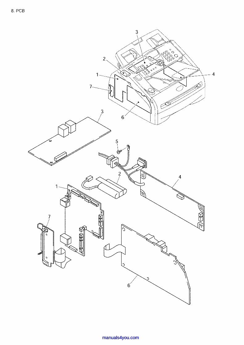
manuals4you.commanuals4you.com

LIST8(PCB)
REF No. CODE Q'TY DESCRIPTION RECOMMEND SYMBOL REMARK1 LG6141001 1 MAIN PCB ASSY, FAX2820 FOR US/CAN B53K7951 LG6140001 1 MAIN PCB ASSY, FAX2920 B53K8021 LG6086001 1 MAIN PCB ASSY, MFC7220 FOR US B53K7951 LG6065001 1 MAIN PCB ASSY, MFC7225N B53K8021 LG6086002 1 MAIN PCB ASSY, MFC7220 FOR CAN B53K7951 LG6141003 1 MAIN PCB ASSY, FAX2820 FOR BRA B53K7951 LG6086003 1 MAIN PCB ASSY, MFC7220 FOR BRA B53K7952 LG6167001 1 BATTERY ASSY, FAX2920/MFC7225N √3 LG6074001 1 NCU PCB ASSY, FAX2820/MFC7220 FOR US B53K7843 LG6074011 1 NCU PCB ASSY, FAX2920/MFC7225N B53K7843 LG6074002 1 NCU PCB ASSY FOR CAN B53K7843 LG6233003 1 NCU PCB ASSY FAX2820/MFC7220 FOR BRA B53K786 CHG4 LG6271001 1 PS PCB UNIT, 115V FOR US/CAN4 LG6272001 1 PS PCB UNIT, 115V FOR BRA5 LM2048001 1 SCREW, PAN (S/P WASHER) M3.5X66 LJ9708001 1 HIGH-VOLTAGE PS PCB ASSY7 LG6068001 1 CDCC PCB ASSY, MFC7220/MFC7225N B53K801
FAX2820, FAX2920, MFC7220, MFC7225N 8X5A01, 8X5A07, 8X5A13, 8X5A17
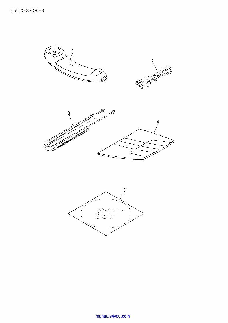
manuals4you.commanuals4you.com
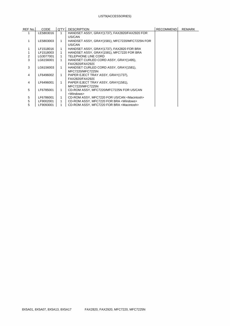
LIST9(ACCESSORIES)
REF No. CODE Q'TY DESCRIPTION RECOMMEND REMARK1 LE5803016 1 HANDSET ASSY, GRAY(1737), FAX2820/FAX2920 FOR
US/CAN1 LE5803003 1 HANDSET ASSY, GRAY(1581), MFC7220/MFC7225N FOR
US/CAN1 LF1518016 1 HANDSET ASSY, GRAY(1737), FAX2820 FOR BRA1 LF1518003 1 HANDSET ASSY, GRAY(1581), MFC7220 FOR BRA2 LG3077001 1 TELEPHONE LINE CORD3 LG6156001 1 HANDSET CURLED CORD ASSY, GRAY(1495),
FAX2820/FAX29203 LG6156003 1 HANDSET CURLED CORD ASSY, GRAY(1581),
MFC7220/MFC7225N4 LF6496002 1 PAPER EJECT TRAY ASSY, GRAY(1737),
FAX2820/FAX29204 LF6496001 1 PAPER EJECT TRAY ASSY, GRAY(1581),
MFC7220/MFC7225N5 LF6785001 1 CD-ROM ASSY, MFC7220/MFC7225N FOR US/CAN
<Windows>5 LF6786001 1 CD-ROM ASSY, MFC7220 FOR US/CAN <Macintosh>5 LF9002001 1 CD-ROM ASSY, MFC7220 FOR BRA <Windows>5 LF9093001 1 CD-ROM ASSY, MFC7220 FOR BRA <Macintosh>
FAX2820, FAX2920, MFC7220, MFC7225N 8X5A01, 8X5A07, 8X5A13, 8X5A17

manuals4you.commanuals4you.com

LIST10(PRINTED MATERIALS)
REF No. CODE Q'TY DESCRIPTION RECOMMEND REMARK1 LF6772001 1 USER'S GUIDE FOR US/CAN <ENGLISH>1 LF6772002 1 USER'S GUIDE FOR CAN <FRENCH>
FAX2820, FAX2920, MFC7220, MFC7225N 8X5A01, 8X5A07, 8X5A13, 8X5A17
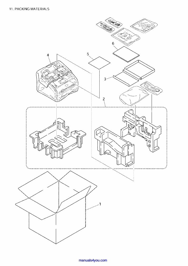
manuals4you.commanuals4you.com

LIST11(PACKING MATERIALS)
REF No. CODE Q'TY DESCRIPTION RECOMMEND REMARK1 LF6774001 1 CARTON, BROTHER, FAX2820 √1 LF6779001 1 CARTON, BROTHER, FAX2920 √1 LF6788001 1 CARTON, BROTHER, MFC7220 √1 LF9004001 1 CARTON, BROTHER, MFC7225N √2 LF6500001 1 POLYSTYRENE PAD ASSY3 LF6748001 1 OPTION CARTON4 LC0540001 1 BAG, 700X800H CHG5 UU0456001 1 PROTECTION PAPER6 LF6777001 1 QUICK SETUP GUIDE, FAX2820/FAX2920 FOR US/CAN
<ENGLISH>6 LF6791001 1 QUICK SETUP GUIDE, MFC7220/MFC7225N FOR US/CAN
<ENGLISH>6 LF6777002 1 QUICK SETUP GUIDE, FAX2820 FOR CAN <FRENCH>6 LF6791002 1 QUICK SETUP GUIDE, MFC7220 FOR CAN <FRENCH>
FAX2820, FAX2920, MFC7220, MFC7225N 8X5A01, 8X5A07, 8X5A13, 8X5A17
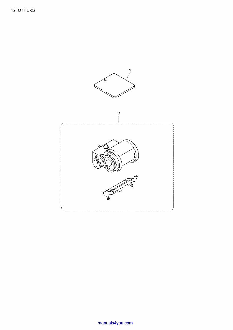
manuals4you.commanuals4you.com

List12(OTHERS)
REF No. CODE Q'TY DESCRIPTION RECOMMEND REMARK1 LM4726001 1 CHECK JIG2 LM4581001 1 PAPER FEEDING KIT
FAX2820, FAX2920, MFC7220, MFC7225N 8X5A01, 8X5A07, 8X5A13, 8X5A17

PL-FAX105 8C5A01 Ver.B-1
manuals4you.commanuals4you.com
Recommended