Powerduct Series Busway
Feeder and Plug-In Busway

Powerduct Series Busway
Table of Contents
Installing Busway
Introduction………………………………………………………………………… 1
General Information………………………………………………………………….. 1 Handling (including unpacking)……………………………………………………… 1 Storage Precautions………………………………………………………………… .. 2
Pre-Installation Procedure……………………………………………………………. 3
Busway Installation…………………………………………………………………… 3
Installing Indoor Busway
Horizontal Mounting………………………………………………………………… 4
Vertical Mounting…………………………………………………………………… 5
Joining Lengths……………………………………………………………………… 6-7
Expansion Fittings………………………………………………………………….. 8
Installing and Removing Tap-Off Unit
Installing Tap-Off Unit……………………………………………………………. 9
Removing Tap-Off Unit……………………………………………………………. . 9
Installing Outdoor Busway
Installation Procedures……………………………………………………………. 10
Busway Maintenance Procedures
Maintenance Procedures…………………..………………………………………. 11
Inspecting Current-Carrying Components…..…………………………………….. 11
Energizing………………………………..………………………………………... 11
Busway Installation Checklist………………………………………. 12-13

Powerduct Series Busway
General Imformation
Introduction
This publication is a guide of practical information containing instructions for the handling ,installation ,operation
and maintenance of Powerduct busway and some busway accessories .These recommendations and guidelines
will be valuable to electrical engineers, electrical contractors, electricians, maintenance engineers and others.
Responsible for the handling, installation, operation and maintenance of Powerduct .This manual will be updated
to reflect certain relevant developments in Powerduct.
General Information
Please read the following warning very carefully before proceeding with any installation, operation and mainte-
nance of Powerduct catalogue
Warning:
Please take extreme caution when working in or around electrical equipment as there is a hazard of electrical shock
can cause severe injury.
1. It is important to have good communications with air-conditioning, plumbing and heating contractors and
other site personnel for proper planning and coordination ,which will result in good busway layout.
2. The successful operation of Powerduct will depend to a large degree on proper handling ,installation, opera-
tion and maintenance as per stated in this manual .Failure to follow fundamental installation and maintenance
requirements could lead to personal injury and subsequent damage to the busway (or even loss of the
busway) and other property.
Handling (including unpacking) These guidelines are provided to help reduce the risk of personal injury and equipment damage during handling.
1. Always take good care while unpacking.
2. Use nail pullers for unpacking wooden crates to void damage.
3. Take good care when handling busway. Do not subject busway to twisting, denting impact and from of rough
handling which can result in damage to internal components
and the housing or its finish.
4. Never use bus bar ends for lifting busway sections fittings. Apart from running the risk of dropping the bus
duct .this method of lifting busway can also cause injury .If a crane (overhead or other) is used for busway
installation , use nylon straps to balance the weight of each lift.
1
Figure 1a. Void rough handling Figure 1b. Do not use busbar
ends for lifting
Figure 1c. Use a balanced set
up for lifting busduct section

Powerduct Series Busway
Installing Busway
5. Open up busway packaging sufficiently to check it for concealed damage as well as to make
sure shipment is complete end correct.
6. If the busway are not required for immediate installation and need to be stored for some time
Restore the packaging for protection.
7. Know the capacity of the moving means (overhead crane, hoists block & tackle etc.)
available to handle the weight of the busway sections and fitting .Refer to Powerduct
Catalogue to check the weight of straight lengths.
8. Forklift trucks can be used to effectively handle busway. With a forklift ,busway can be hoisted between floors
with ease. Power operated lifts or elevators can be used to effectively move busway between elevations.
9. Do not drag the busway across the floor .this can damage the housing and finish (paintwork)
Storage Precautions
Before storing, unpack thoroughly to make a check of the Busway for possible concealed damage and notify the
shipper immediately for any damage reported. If the Busway is free of damage, restore the packing until ready for
installation. Store indoors in a clean, dry area, preferably close to the installation points. Protect the Busway from
mechanical damage and any contact with or exposure to corrosive fumes, liquids, salts, or concrete. Failure to store
and protect the busway properly can cause serious damage and will void the warranty.
1. Always store busway in clean and dry place having a uniform temperature to prevent condensation. Ensure that
the busway are protected from dirt ,fumes, water and physical damage.
2. Do not store busway in a outdoor environment
If busway must be stored outdoor, make sure that the busway are securely covered to provide maximum protec-
tion from weather (mainly rain) and dirt (see fig 2)
3. Out door busway (weather proof) and indoor busway should be treated the same Outdoor busway are the same
as indoor busway until they are fully installed.
4. For vertical rise, it is good practice to store busway on the floor above where they will be installed ,so that they
can be easily lowered into position.
2
Busway Store
Figure 2. Outdoor Storage method

Powerduct Series Busway
Installing Busway
Pre-Installation Procedure
If possible, please deliver the busway to its installation location before unpacking. Large labels on each shipping
carton or crate designate the items contained. Additionally, each Busway piece is identified with an serial number
label. Inspect each Busway piece for possible damage or contamination. Contact surfaces must be clean. However,
do not attempt to polish tarnished contact surfaces. Check to ensure that joint insulators are not damaged or
cracked and are firmly in place. Mega ohm test each piece before installation.
Busway Installation
Establish the bus bar phase sequence (Top side is labeled) to determine how the Busway is to be installed, so that
correct phasing is maintained throughout the system. Note that phase transposition lengths, when furnished, may
relocate the Top to the opposite side of a Busway run. Each Busway section has a “bar end” and a “joint end”, as
illustrated in Figure 3. Normally the busway is oriented end with bar ends pointing away from the source. In
vertical risers installations, it is easier to lower the busway into place than it is to raise it.
If installation drawings have been furnished, information regarding the orientation of the Busway end for end, and
location of the Top side, as well as other pertinent data, will be furnished. These drawings should be followed
carefully to ensure a proper Busway system.
Figure 3. The bar end and joint end of the busway.
3

Powerduct Series Busway
Installing Indoor Busway
Horizontal Mounting
Overhead Support
For overhead-supported busway, ½ inch drop rods are recommended with a maximum 2.5meter spacing. Drop rods
and other hardware must be furnished by the installer. Figure 4 illustrates mounting dimensions for typical
installations.
∗ Maintain good alignment of the drop rods along the busway run.
∗ Do not support busway at the joints.
∗ After the busway is secured in the hangers, adjust the hangers on the rods for the correct elevation.
∗ Sway braces (furnished by the installer) may be required to keep the run straight or to prevent rotation.
∗ Manufacturer strongly recommended each 2.5 meter busway adjacent must have busway cleat supported.
Please check with manufacturer if cleat quantity provided is insufficient.
Figure 4. Dimension between drop rods for dual-hanger installations.
Bars per
Phase
Copper Dim
(mm)
Aluminum Dim
(mm)
Ampere
Rating
Busway
W
Hanger
A
Ampere
Rating
Busway
W
Hanger
A
1
400 89
260
400 125
260
600 99 600 140
800 114 800 144
1000 129 1000 159
1200 144 1200 179
1350 159 1350 129
356 1600 179 1600 234
2000 219
356
2000 269
2500 254 2500 375
2
3200 295
470
3200 405
4000 375 4000 475 572
5000 445 572
470
Table 1. Busway and hanger mounting
dimensions, as illustrated in Figure 4
Material use for busway support channel.
• Suggest to use 12mm or 1/2 inch of steel rod.
• Dimension between drop rods is normally 2m.
• It is suggest to use 40mm x 3mm support channel
for 2000A or below busway model while 50mm x
6mm for 2500A or above busway.
• Please refer to below data during busway installa-
tion.
4
Powerduct Series Busway
Installing Indoor Busway
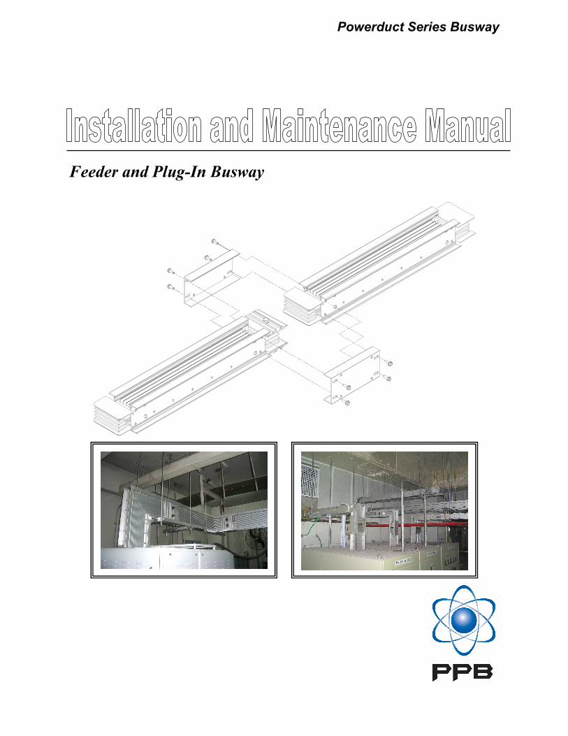
Vertical Mounting Support busway on maximum 4.8 meter centers. Use Table 1 to determine the number of springs required based on
busway weight. After placing the length of busway through the floor, follow this procedure to assemble hangers to
the busway, as illustrated in Figure 5. For convenience in assembly, step 8 may be completed before the hangers
are attached to the busway.
1. Loosen the hanger bolt , shown in Figure 5.
2. Assembly the hangers to each side of the busway.
3. Position the hangers on the busway so that the base channel rests on the floor or other support. A floor flange
may be placed under the hanger, but it will not support the busway weight.
4. Fit the hanger clamps to the busway housing and hand tighten the hanger bolts .
5. Anchor the base channels to their supports.
6. Tighten the hanger bolts
7. Install the next length and make the joint assembly.
8. If springs are furnished, they must be adjusted as shown in Figure 5.
Figure 5. Rigid and spring hanger installation
5

Powerduct Series Busway
Installing Indoor Busway
Using the final adjustment nuts, set the springs on the hangers to the dimension . With the springs adjusted, hold
nut in position and tighten jam nut against nut to retain the spring setting. Tighten all jam nuts using this procedure.
Note that when you are calculating the dimension for the bottom floor of a riser with an elbow and busway directly
below the floor, the following must be included in the meter calculation:
• Busway below the floor to the elbow
• The elbow
• 2.5 meter of horizontal busway
For the riser to function as a free end, the last horizontal hanger must be 8 feet from the bottom elbow.
9. After the busway run is installed, starting at the top hanger raise the initial adjusting nuts of all hangers to the top
of the spring studs. The studs are crimped to hold the nuts in the uppermost position.
Amperes Busway Weight, Kg/m
Copper
3 Wire 4 Wire 3 Wire 4 Wire
225 8 9 7 8
400 8 9 7 8
600 9 11 8 9
800 12 14 8 10
1000 15 18 10 12
1200 17 21 11 13
1350 20 25 12 14
1600 24 29 13 16
2000 32 40 18 21
2500 39 49 23 27
3000 50 62 30 34
4000 68 84 38 44
5000 82 101 - -
Aluminum
Busway Weight,
Kg
No. of Springs Re-
quired per floor
0 — 250 2
251 — 550 4
Over 550 6
Table 2. Busway Weights.
Table 3. Number of busway springs
required per busway weight.
6
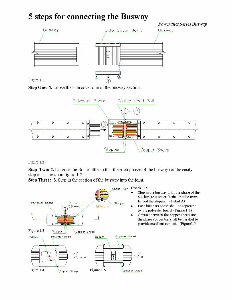
Joining Lengths
Use the following procedure to join two lengths of Busway.
1. Remove at least one joint cover, shown in Figure 6. From the two pieces to be joined, retaining the bolts.
2. Align the sections to be joined by matching up the TOP labels attached to the ends of each section. Use tools
provided by manufacturer to ease the installation. See Figure 7 and 8.
3. If necessary, loosen the joint bolt slightly.
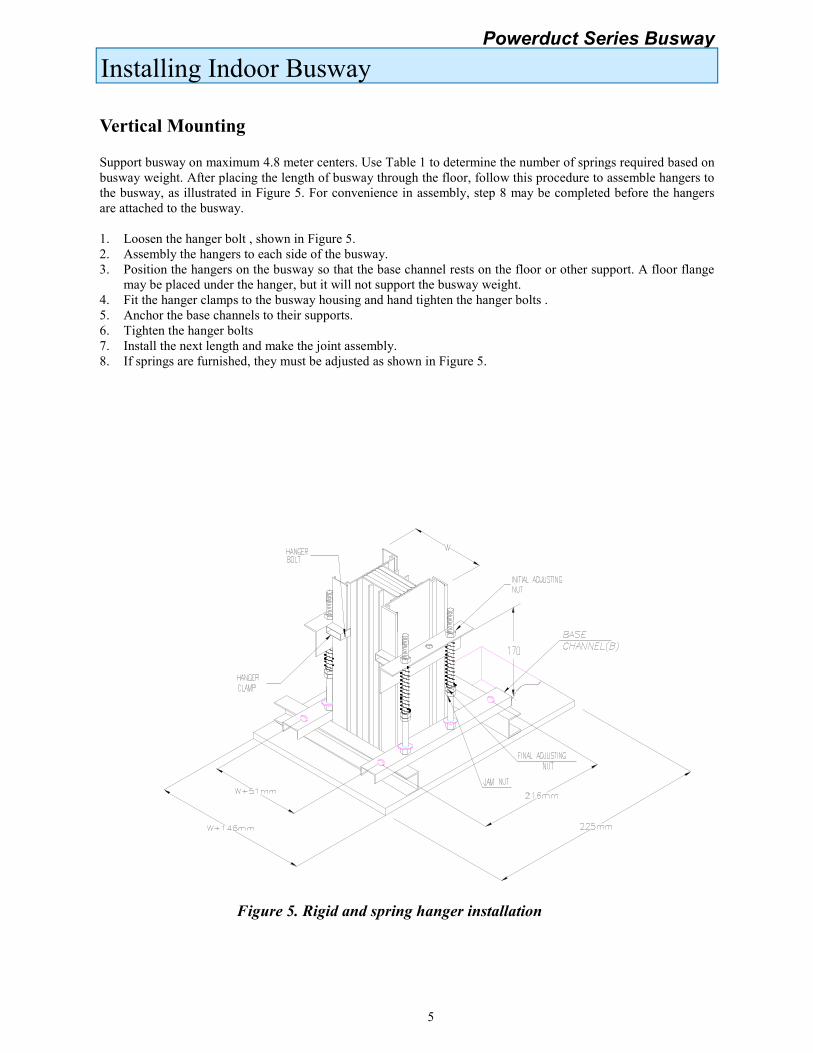
4. Slide the sections together. Ensure that the busbars interweave the insulators, as shown in Figures 10,11 and
12.

Powerduct Series Busway
Installing Indoor Busway
5. The standard distance between the joint cover bolts is 233.5 mm, as shown in Figure 11. However, the joint is
also adjustable, as shown in Figure 10 & 12. Simply move the sections in or out to the desired length, as shown,
and remove the twist-outs in both joint cover, as shown in Figure 6.
6. If the joint covers are not already in place, reattach them and hand tighten the mounting screws.
7. Inspect the busway run for straightness in all planes and make any adjustments necessary for good alignment.
8. **Note: Important to visually inspect and to ensure that after the phases bus bars sloped in the joint, the joint
contact must be parallel aligned with the phases bus bars contact before the installation of the joint covers.
9. Grease has been applied to the joint bolt head and threads to reduce friction. Do not remove this grease.
10. Tighten the joint bolt to 50 lbs-ft (68 N-m) with a ¾ inch or 19mm socket wretch. When the Belleville
washers on both sides are flattened, the bolt is fully tightened. If the double head bolt is used, tighten until the
bolt head shear off. (No torque wrench is required).
11. Tighten all joint cap screws to 25lb-ft (34 N-m) with a 13-mm socket wrench.
12. During installation, occasionally mega ohm test the assembly to check for any improperly made joints.
Resistance should not drop below 1 mega ohm per 100 feet of busway. Mega ohm test the complete run before
energizing.
Figure 6. Joint Cover Figure 7. Installation tool kit
Figure 8. Installation tool kit
using method
7
Figure 9. Installation busway
The wrong way for Installation busway
The correct way for Installation busway
α
Powerduct Series Busway
Installing Indoor Busway
Figure 12. Busway Joint at the maximum distance
Figure 10. Busway joint at the minimum distance Figure 11. Busway joint at the standard distance
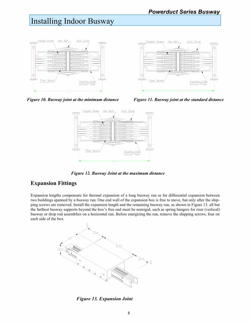
Expansion Fittings
Expansion lengths compensate for thermal expansion of a long busway run or for differential expansion between
two buildings spanned by a busway run. One end wall of the expansion box is free to move, but only after the ship-
ping screws are removed. Install the expansion length and the remaining busway run, as shown in Figure 13. all but
the farthest busway supports beyond the box’s free end must be nonrigid, such as spring hangers for riser (vertical)
busway or drop rod assemblies on a horizontal run. Before energizing the run, remove the shipping screws, four on
each side of the box.
Figure 13. Expansion Joint
8
Powerduct Series Busway
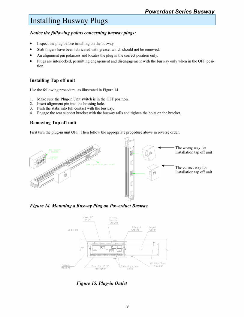
Installing Busway Plugs
Notice the following points concerning busway plugs:
• Inspect the plug before installing on the busway.
• Stab fingers have been lubricated with grease, which should not be removed.
• An alignment pin polarizes and locates the plug in the correct position only.
• Plugs are interlocked, permitting engagement and disengagement with the busway only when in the OFF posi-
tion.
Installing Tap off unit
Use the following procedure, as illustrated in Figure 14.
1. Make sure the Plug-in Unit switch is in the OFF position.
2. Insert alignment pin into the housing hole.
3. Push the stabs into full contact with the busway.
4. Engage the rear support bracket with the busway rails and tighten the bolts on the bracket.
Removing Tap off unit
First turn the plug-in unit OFF. Then follow the appropriate procedure above in reverse order.
Figure 14. Mounting a Busway Plug on Powerduct Busway.
Figure 15. Plug-in Outlet
The correct way for
Installation tap off unit
The wrong way for
Installation tap off unit
9

Powerduct Series Busway
Installing Outdoor Busway
Figure 16. Assembly of outdoor busway joint. Correct way to assembly of joint shields is
illustrated.
Steps in installing outdoor busway system
(For IP 66 & 67 Feeder Type is as shown
in figure 13)
• Gasket will be provided for IP 66 & 67 standard
feeder as shown in Figure 17.
• Paste it on inner part of side cover.
• Attach plastic splice on the top of joint as shown
in Figure 18.
• Apply caulking to specific seams to enhance
gasketed areas as shown in figure 19.
• Joint two feeder together, and eventually attach
side cover on both sides of the joint which is
shown in Figure 16.
• Please refer to Figure 16 to ease installation.
Figure 17. Gasket (sponge)
Figure 18. Water resistant / Outdoor joint
Figure 19. Joint Caulking
Installation Procedures
10

Powerduct Series Busway
Busway Maintenance Procedures
Maintenance Procedures
• Keep busway free of dust, dirt and/or foreign matter. Moisture from roof leaks or dripping pipes should be
eliminated.
• Inspect the busway system periodically. An infrared thermometer may be used to thermally scan the run to
identify potential hot spots.
• During initial installation, joint bolts are to be tightened until the outer bolt head shears off (approx. 50lbs-ft)
using the double-headed joint bolt.
• Check torque after six (6) months; tighten to 50 lbs-ft. as required. Re-check torque at least annually thereaf-
ter.
Inspecting Current-Carrying Components
• Carefully inspect all visible electrical joints and terminations for tightness of bolts, nuts, and other fasteners.
• Check for signs of overheating at joints, terminations and fuse clips.
• Check for deterioration in insulating material or melting of sealing compound.
• Ensure that the condition that caused any overheating has been eliminated.
• Check for missing or broken parts, proper spring tension, free movement, rust or corrosion, dirt, excessive
wear, arc spatter, sooty deposits, and tracking. Clean or replace parts as required.
Do-energize the busway before performing any of the following operations.
• If there are signs of overheating, visually check for deterioration or contamination of insulation and contact
surfaces. Check tightness of nuts, bolts, etc.
• Check for missing or broken parts, corrosion, wear, dirt or signs of arcing. Clean or replace parts as required.
After any repair or rework, isolate the busway and megger the busway system. Minimum readings should be
no less than:
Megaohms = 200 / length of run in feet OR 66 / length of run in meters.
11
Powerduct Series Busway
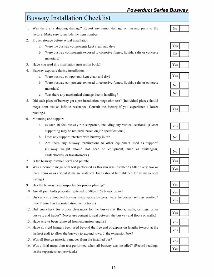
Busway Installation Checklist
1. Was there any shipping damage? Report any minor damage or missing parts to the
factory. Make sure to include the item number.
2. Proper storage before actual installation
a. Were the busway components kept clean and dry?
b. Were busway components exposed to corrosive fumes, liquids, salts or concrete
materials?
3. Have you read this installation instruction book?
4. Busway exposure during installation.
a. Were busway components kept clean and dry?
b. Were busway components exposed to corrosive fumes, liquids, salts or concrete
materials?
c. Was there any mechanical damage due to handling?
5. Did each piece of busway get a pre-installation mega ohm test? (Individual pieces should
mega ohm test as infinite resistance. Consult the factory if you experience a lower
reading.)
6. Mounting and support
a. Is each 10 feet busway run supported, including any vertical sections? (Closer
supporting may be required, based on job specifications.)
b. Does any support interfere with busway joint?
c. Are there any busway terminations to other equipment used as support?
(Busway weight should not bear on equipment, such as switchgear,
switchboards, or transformers.)
7. Is the busway installed level and plumb?
8. Was a periodic mega ohm test performed as this run was installed? (After every two or
three items or as critical items are installed. Joints should be tightened for all mega ohm
testing.)
9. Has the busway been inspected for proper phasing?
10. Are all joint bolts properly tightened to 50lb-ft (68 N-m) torque?
11. On vertically mounted busway using spring hangers, were the correct settings verified?
(See Figure 3 in the installation instructions.)
12. Did you check for proper clearances for the busway at floors, walls, ceilings, other
busway, and trades? (Never use cement to seal between the busway and floors or walls.)
13. Have screws been removed from expansion lengths?
14. Have no rigid hangers been used beyond the free end of expansion lengths (except at the
farthest end) to allow the busway to expand toward the expansion box?
15. Was all foreign material removes from the installed bus?
16. Was a final mega ohm test performed when all busway was installed? (Record readings
on the separate sheet provided.)
Yes
No
Yes
No
Yes
No
No
Yes
Yes
No
No
Yes
Yes
Yes
Yes
Yes
Yes
Yes
Yes
Yes
Yes
12

Powerduct Series Busway
Busway Installation Checklist
17. Verify the orientation of weep holes. Are all open weep holes in joint caps, elbows and
shields facing downward? (Do not remove shield plugs or weep-hole plugs in top or side
positions.)
18. Are all drain holes clear in both busway and joint caps? (all construction debris
removed.)
19. Were joints assembles within the width of the housing ground plates?
20. Are joint cap bolts properly tightened to 25 lb-ft (34 N-m)?
21. Were shields aligned at the edges of housing ground plates and all springs seated
properly?
22. Were isolation joints screwed in place before and boxes (when present) were installed?
Yes
Yes
Yes
Yes
Yes
Notes and comments.
Note: This checklist is intended to insure a sound installation of Powerduct Busway. It is not intended to cover all
items related to the installation, successful startup, and long-term use of the product and in no wat relieves the con-
tractor of his obligation to meet all specification and code requirement.
Installation Contractor
Signed Dated
13
Yes

Powerduct Series Busway

Recommended