CAM ANALYSIS APPARATUS Experiment -1
OBJECTIVE: -
1. To Study the motion of follower with the given profile of the cam.
2. To plot the n-q (Follower displacement Vs Angle of rotation) curves for different cam
follower pairs
THEROY:-
Cams precede the development of modern Mechatronics but still have their uses in
a variety of devices. They convert the rotation of a shaft into a specified linear motion of a
follower. A typical example is the overhead cam shaft in an internal combustion engine.
Many applications have been replaced by computer controlled machines using hydraulic,
pneumatic and electric actuators. The motion of the follower depends on the shape of the cam.
The most basic motion might be a simple quick stroke (e.g. to knock something off a conveyer
belt. A cam as shown in the diagram would be suitable. A key part of your work is to
understand how to produce the cam shape that produces the required motion. You should
already know the relationship between displacement, velocity and acceleration.
For a displacement x, the velocity is v = dx/dt = gradient of the displacement - time graph.
This is clearly zero at any time where the profile is circular. We must consider the inertia
force produced by the sudden movement which produces acceleration and deceleration of the
follower. The acceleration is a = dv/dt = the gradient of the velocity – time graph. It is normal
to round the corners to avoid excessive wear.
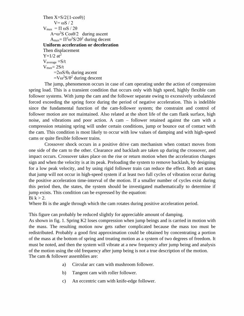
DISPLACEMENT, VELOCITY AND ACCELERATION OF FOLLOWER
Consider a simple cam with a pointed follower. The centre lines of the follower and cam are
the same. The follower is restrained to move along the centre line by the guides. The
displacement of the follower is x and a typical displacement – angle graph is shown
Cam may be defined as a rotating and reciprocating element of a mechanism which imparts a
reciprocating or oscillating motion to another element called follower. The cams are of the
disc or cylindrical types and the follower are of knife edge, roller or flat faced.
The usual motions for the follower are S.H.M
Let S= lift of the follower
X= Displacement of the follower when crank has turned
Then X=S/2{1-cosθ)}
V= ωS / 2
Vmax = Π ωS / 2θ
A=ω2S Cosθ/2 during ascent
Amax= Π2ω2S/2θ2 during decent
Uniform acceleration or deceleration
Then displacement
Y=1/2 at2
Vaverage =S/t
Vmax= 2S/t
=2ωS/θ0 during ascent
=Vω2S/θ2 during descent
The jump, phenomenon occurs in case of cam operating under the action of compression
spring load. This is a transient condition that occurs only with high speed, highly flexible cam
follower systems. With jump the cam and the follower separate owing to excessively unbalanced
forced exceeding the spring force during the period of negative acceleration. This is indelible
since the fundamental function of the cam-follower system; the constraint and control of
follower motion are not maintained. Also related at the short life of the cam flank surface, high
noise, and vibrations and poor action. A cam – follower retained against the cam with a
compression retaining spring will under certain conditions, jump or bounce out of contact with
the cam. This condition is most likely to occur with low values of damping and with high-speed
cams or quite flexible follower trains.
Crossover shock occurs in a positive drive cam mechanism when contact moves from
one side of the cam to the other. Clearance and backlash are taken up during the crossover, and
impact occurs. Crossover takes place on the rise or return motion when the acceleration changes
sign and when the velocity is at its peak. Preloading the system to remove backlash, by designing
for a low peak velocity, and by using rigid follower train can reduce the effect. Roth art states
that jump will not occur in high-speed system if at least two full cycles of vibration occur during
the positive acceleration time-interval of the motion. If a smaller number of cycles exist during
this period then, the states, the system should be investigated mathematically to determine if
jump exists. This condition can be expressed by the equation:
Bi k > 2.
Where Bi is the angle through which the cam rotates during positive acceleration period.
This figure can probably be reduced slightly for appreciable amount of damping.
As shown in fig. 1. Spring K2 loses compression when jump beings and is carried in motion with
the mass. The resulting motion now gets rather complicated because the mass too must be
redistributed. Probably a good first approximation could be obtained by concentrating a portion
of the mass at the bottom of spring and treating motion as a system of two degrees of freedom. It
must be noted, and then the system will vibrate at a new frequency after jump being and analysis
of the motion using the old frequency after jump being is not a true description of the motion.
The cam & follower assemblies are:
a) Circular arc cam with mushroom follower.
b) Tangent cam with roller follower.
c) An eccentric cam with knife-edge follower.
DESCRIPTION:
Apparatus is a motorized unit consisting of a camshaft driven by a variable speed motor. The
shaft runs in a double bearing. The free end of the camshaft has a facility to mount the cam
easily.
The follower is properly guided in gunmetal bushes and the type of follower can be changed
according to the cam under test. Graduated circular protractor is fitted co-axial with the shaft.
And a Dial Gauge fitted on the follower shaft is used to note the follower displacement for the
angle of cam rotation. A spring is used to provide controlling force to the follower system.
Weights on the follower shaft can be adjusted as per the requirement. An arrangement is
provided to regulate the speed. The apparatus is very useful for testing the cam performance for
jump phenomenon during operation. On this apparatus the effect of change of inertia forces on
jump action of cam-follower during operation can be observed. It is useful for testing various
cam & follower pairs. Three cams and three followers will be supplied with the apparatus.
Theses are already hardened to reduce the wear.
UTILITIES REQUIRED:
Electricity supply 230 VAC, single Phase
Stroboscope (Optional)
PROCEDURE:
1. Fix the required cam and follower to be tested.
2. Bring the cam and follower to zero position
3. Rotate the cam slowly and note down the angle of rotation of the cam at regular
interval and note the corresponding displacement of follower
4. Plot the graph between displacement of the follower and the angle of rotation of cam
5. Adjust the speed of motor to a particular mark with the help of variac.
6. Measure the RPM and stroke of the cam and follower
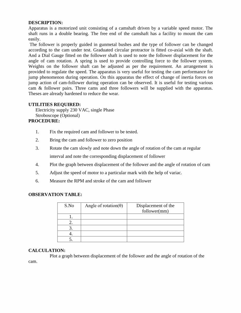
OBSERVATION TABLE:
S.No Angle of rotation(θ) Displacement of the
follower(mm)
1.
2.
3.
4.
5.
CALCULATION:
Plot a graph between displacement of the follower and the angle of rotation of the
cam.
WHIRLING OF SHAFT APPARATUS EXPERIMENT - 2
OBJECT: - To observe the modes of vibration
To determine the critical speed of the given shaft with the given end conditions.
THEORY:-
When any elastic body such as spring beam & shaft are displaced by the application of
external forces & then released. They execute a vibratory motion. When the particles of the
shaft or any disc move approximately perpendicular to the axis of shaft. Then the vibrations
are known as transverse vibration. In this case, the shaft is straight & bends alternately &
bending stresses are induced in the shaft. When a shaft is fixed at both ends, normally the
centre of gravity will displace from the axis of rotation at a very lower amount. As a result of
this displacement, the centre of gravity is subjected to a centripetal acceleration as soon as
the shaft begins to rotate.
The inertia force acts radially outwards & bends the shaft. The bending of shaft is not
only depends upon the value of eccentricity. But also depends upon the speed at which the
shaft rotates. Consider a shaft AB of length L, carrying a load at any point of shaft. When
some amount deflection will be given to it then released, it will make transverse vibration.
The deflection of the shaft is proportional to load W & if the beam is deflected beyond the
static equilibrium position, then the load will vibrate with some harmonic motion. If σ is the
static deflection due to load W, then the natural frequency of free transverse vibration is.
Then for simply supported beam with a uniformly distributed load of W per unit length, σ
can be find out by using formula
Where, W = weight / unit length (Nm)
Then for fixed beam with a uniformly distributed load of W per unit length
σ can be find out by using following formula
In actual practice, a rotating shaft carries different mountings & accessories in the from of
gears, pulleys etc. when the gears or pulleys are put on the shaft, the centre of gravity of the
pulley or gear does not coincide with the centre line of the bearing or with the axis of the
shaft, when the shaft is stationary. This means that the centre of gravity of the pulley or gear
is at a certain distance from the axis of rotation and due to this, the shaft is subjected to
centrifugal force. This force will bent the shaft, which will further increase the distance of
centre of gravity of the pulley or gear from the axis of rotation. This correspondingly
increases the value of centrifugal force, which further increase the distance of centre of
gravity from the axis of rotation. The bending of shaft is not only depends upon the value of
eccentricity but also depends upon the speed at which the shaft rotates. The speed at which
4985.0
2
1== g
nF
EIWLX
4
3845=
EIWL
384
4
=

the shaft runs. So that the additional deflection of the shaft from the axis of rotation becomes
infinite, is known as critical or whirling speed.
If Nc is the critical or whirling speed in r.p.s.
Then
The critical or whirling speed is same as the natural frequency of transverse vibration, but its
unit will be revolutions per second. Dunker ley’s method is used to determine the critical
speed of a shaft, which may be subjected to uniformly distributed load, A shaft supported
with short bearings is assumed to be a simply supported shaft, while shaft supported with
long bearings (or journal bearings) assumed to have both end fixed.
When a shaft rotates, it will go in to transverse vibration .If the shaft is out of balance, the
resulting centrifugal force will induce the shaft to vibrate. When the shaft rotates at a speed
equal to the natural frequency of transverse oscillations, This vibration becomes large and
shows up as a whirling of the shaft. It also occurs at multiples of the resonant speed. This can
be very damaging to heavy rotary machines such as turbine generator sets and the system
must be carefully balanced to reduce this effect and designed to have a natural frequency
different to the speed of rotation. When starting or stopping such machinery, the critical
speeds must be avoided to prevent damage to the bearings and must be avoided to prevent
damage to the bearings and turbine blades.
Suppose a shaft rotates, centrifugal force will cause it to bend out. Let the deflection of the
shaft be r. The distance to the centre of gravity is then r + e.
The shaft rotates at ω rad/s. The transverse stiffness is kt N/m
The deflection force is hence F = Kt r
The centrifugal force is M ω2 (r + e)
g
CN =2
RPSg
NC2
1=

Equating force we have
kt=Mω2(r+e) from which
It has already seen that
From this we see that when ωn = ω r = e/o which is infinity. This means that no matter how
small the imbalance distance e is, the shaft will whirl at the natural frequency. Balancing
does help but can never be perfect so whirling is to be avoided on the best of machines.
The frequencies at which whirling occurs are calculated by the same methods as for
transverse vibrations of beams
SIMPLY SUPPORTED – The ends are free to rotate normal to the axis (e.g. self aligning
bearings)
Where n is the mode (i.e. n=1, 2, 3, 4………….)
FIXED ENDS (i.e Fixed bearing or chucks)
The lowest critical speed is
The highest Critical Speed is
Where n=1, 2, 3, 4………………
ttt k
eM
k
rM
k
ermr
222 )( +=
+=
)1(2
2
t
tk
Mk
eMr
−
=
1)1(2
22
22
−
=
−
==
n
n
n
nt ee
rM
k
4
2
2 WL
gEInf
=
4562.3
WL
gEIf n =
4
2
2
1
2 WL
gEInf n
+=
n=1
n=2
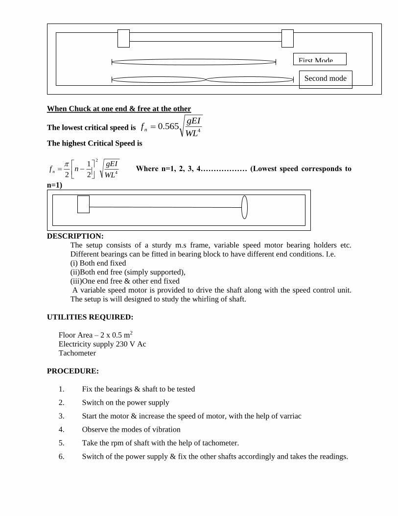
When Chuck at one end & free at the other
The lowest critical speed is
The highest Critical Speed is
Where n=1, 2, 3, 4……………… (Lowest speed corresponds to
n=1)
DESCRIPTION:
The setup consists of a sturdy m.s frame, variable speed motor bearing holders etc.
Different bearings can be fitted in bearing block to have different end conditions. I.e.
(i) Both end fixed
(ii)Both end free (simply supported),
(iii)One end free & other end fixed
A variable speed motor is provided to drive the shaft along with the speed control unit.
The setup is will designed to study the whirling of shaft.
UTILITIES REQUIRED:
Floor Area – 2 x 0.5 m2
Electricity supply 230 V Ac
Tachometer
PROCEDURE:
1. Fix the bearings & shaft to be tested
2. Switch on the power supply
3. Start the motor & increase the speed of motor, with the help of varriac
4. Observe the modes of vibration
5. Take the rpm of shaft with the help of tachometer.
6. Switch of the power supply & fix the other shafts accordingly and takes the readings.
4565.0
WL
gEIfn =
4
2
2
1
2 WL
gEInf n
−=
First Mode
Second mode
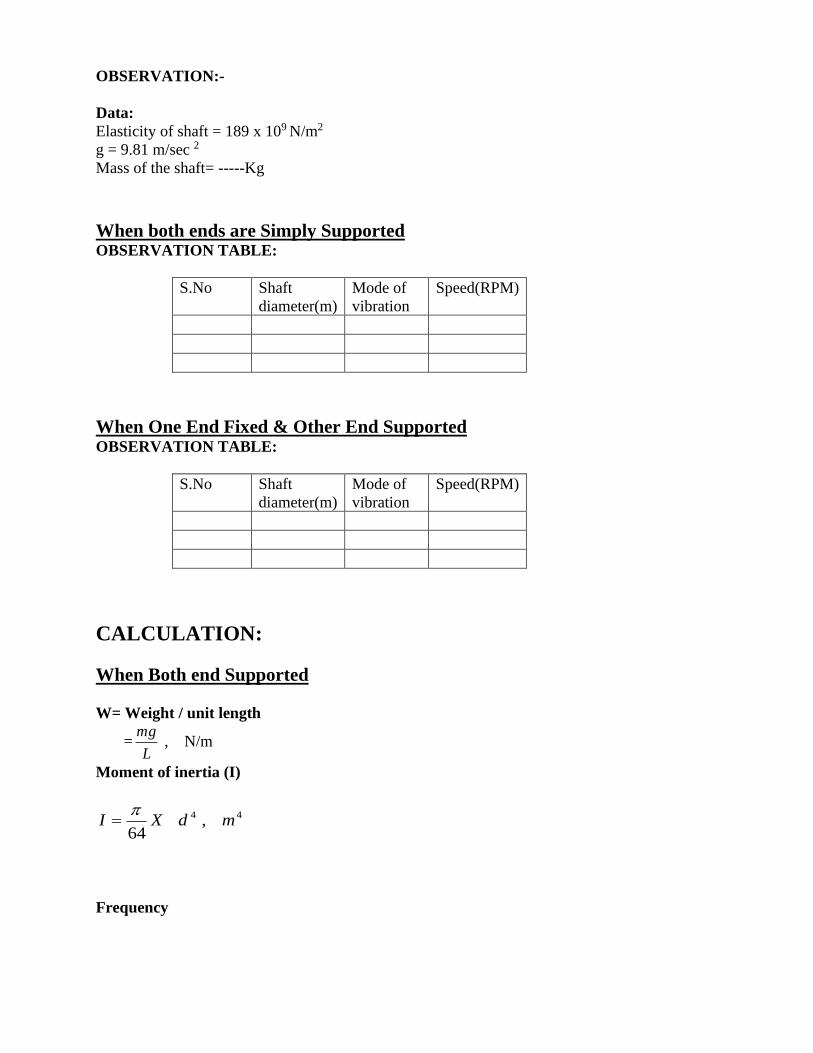
OBSERVATION:-
Data:
Elasticity of shaft = 189 x 109 N/m2
g = 9.81 m/sec 2
Mass of the shaft= -----Kg
When both ends are Simply Supported OBSERVATION TABLE:
S.No Shaft
diameter(m)
Mode of
vibration
Speed(RPM)
When One End Fixed & Other End Supported OBSERVATION TABLE:
S.No Shaft
diameter(m)
Mode of
vibration
Speed(RPM)
CALCULATION:
When Both end Supported
W= Weight / unit length
= , N/m
Moment of inertia (I)
Frequency
L
mg
44 ,64
mdXI
=

Where n is the mode (i.e. n=1, 2, 3, 4………….)
Critical Speed
NC=fn x 60 RPM
When One End Fixed & Other End Supported
W= Weight / unit length
= , N/m
Moment of inertia (I)
The Critical Frequency is
Where n=1, 2, 3, 4……………… (Lowest speed corresponds to
n=1)]
Critical Speed
NC=fn x 60 RPM
Result:
L
mg
44 ,64
mdXI
=
4
2
2
1
2 WL
gEInf n
−=

APPARATUS USED: -. Arrangement of Gear train system.
THEORY: -
1. Definition of. Gear train
2. Classification of Gear train
3. Diagrams of different types of Gear train.
4. Working & Construction of different types of Gear train.
5. Advantages & Disadvantages of Gear train
6. Applications of Gear train .
7. Examples of Gear train
GEAR TRAIN:-
A gear train is a combination of gears used to transmit motion from one
shaft to another. It becomes necessary when it is required to obtain large speed reduction
With in a small space. The following are the main types of gear trains:
(i) Simple gear train
(ii) Compound gear train
(iii) Reverted gear train
(iv) Planetary gear train
SIMPLE GEAR TRAIN:-
A series of gears, capable of receiving and transmitting motion
from one gear to another is called a simple gear train. In it, all the gear axes remain fixed
relative to the frame and each gear is on a separate shaft.
Train Value = Number of teeth on driving gear / Number of teeth on driven gear
COMPOUND GEAR TRAIN:-
When a series of gears are connected in such a way that
two or more gears rotate about an axis with the same angular velocity, it is known as
compound gear train. In this type, some of the intermediate shafts.
Train Value = Product of Number of teeth on driving gear / Product of Number of teeth on
driven gear

REVERTED GEAR TRAIN :-
If the axes of the first and last wheels of a compound gear coincide; it is called a reverted
gear train. Such an arrangement is used in clocks and in simple lathes where ‘back gear’ is used
to give a slow speed to the chuck.
Train Value = Product of Number of teeth on driving gear / Product of Number of teeth on
driven gear

PLANETARY OR EPICYCLIC GEAR TRAIN: -
When there exists a relative motion of
axis in gear train, it is called a planetary or an epicyclic gear train (or simply epicyclic gear or
train). Thus in an epicyclic train, the axis of at least one of the gears also moves relative to
the frame.
Consider two gear wheels S and P, the axis of which are connected by an arm a. if
the arm ‘a’ is fixed, the wheels S and P constitute a simple train. However, if the wheel s is
fixed so that the arm can rotate about the axis of S, the wheel P would also move around S.
therefore, it is an epicyclic train.
DIFFERENTIAL GEAR :-
When a vehicle takes a turn, the outer wheels must travel
farther than the inner wheels. In automobiles, the front wheels can rotate freely on their axis
and thus can adapt themselves to the conditions. Both rear wheels are driven by the engine
through gearing. Therefore, some sirt of automatic device is necessary so that the two rear

wheels are driven at slightly different speeds. This is accomplished by fitting a differential
gear on the rear axle.
OBSERVATION & CONCLUSION: -
1. Comparison between simple, compound reverted, epicyclic and differential. Gear train.
2. To calculate the train value.
3. To calculate the speed of any gear.

GOVERNORS Experiment -13
Aim: To study about different types of governors and its applications
Introduction:
Flywheel which minimizes fluctuations of speed within the cycle but it cannot minimize
fluctuations due to load variation. This means flywheel does not exercise any control over mean
speed of the engine. To minimize fluctuations in the mean speed which may occur due to load
variation, governor is used. The governor has no influence over cyclic speed fluctuations but it
controls the mean speed over a long period during which load on the engine may vary. The
function of governor is to increase the supply of working fluid going to the prime mover when
the load on the prime-mover increases and to decrease the supply when the load decreases so as
to keep the speed of the prime-mover almost constant at different loads.
Example: when the load on an engine increases, its speed decreases, therefore it becomes
necessary to increase the supply of working fluid. On the other hand, when the load on the
engine decreases, its speed increases and hence less working fluid is required. When there is
change in load, variation in speed also takes place then governor operates a regulatory control
and adjusts the fuel supply to maintain the mean speed nearly constant. Therefore, the governor
automatically regulates through linkages, the energy supply to the engine as demanded by
variation of load so that the engine speed is maintained nearly constant.

Types of Governors The governors may, broadly, be classified as 1. Centrifugal governors 2. Inertia governors.
3. pickering governors.
Centrifugal Governors:
In these governors, the change in centrifugal forces of the rotating masses due to change
in the speed of the engine is utilized for movement of the governor sleeve. One of this type of
governors is shown in Figure. These governors are commonly used because of simplicity in
operation.
Inertia and Flywheel Governors:
In these governors, the inertia forces caused by the angular acceleration of the engine
shaft or flywheel by change in speed are utilized for the movement of the balls. The movement
of the balls is due to the rate of change of speed instead of change in speed itself as in case of
centrifugal governors. Thus, these governors are more sensitive than centrifugal governors.
Pickering Governors:
This type of governor is used for driving a gramophone. As compared to the centrifugal
governors, the sleeve movement is very small. It controls the speed by dissipating the excess
kinetic energy. It is very simple in construction and can be used for a small machine.
Types of Centrifugal Governors:
Depending on the construction these governors are of two types:
a) Gravity controlled centrifugal governors, and
b) Spring controlled centrifugal governors.
Gravity Controlled Centrifugal Governors:
In this type of governors there is gravity force due to weight on the sleeve or weight of
sleeve itself which controls movement of the sleeve. These governors are comparatively larger in
size.
Spring Controlled Centrifugal Governors:

In these governors, a helical spring or several springs are utilized to control the
movement of sleeve or balls. These governors are comparatively smaller in size.
Gravity controlled centrifugal governors:
There are three commonly used gravity controlled centrifugal governors:
(a) Watt governor (b) Porter governor (c) Proell governor
Watt governor does not carry dead weight at the sleeve. Porter governor and proell governor
have heavy dead weight at the sleeve.
In porter governor balls are placed at the junction of upper and lower arms.
In case of proell governor the balls are placed at the extension of lower arms. The sensitiveness
of watt governor is poor at high speed and this limits its field of application.
Portergovernor is more sensitive than watt governor.
The proell governor is most sensitive out of these three. Watt Governor:
This governor was used by James Watt in his steam engine. The spindle is driven by the output
shaft of the prime mover. The balls are mounted at the junction of the two arms. The upper arms
are connected to the spindle and lower arms are connected to the sleeve as shown in Figure.

We ignore mass of the sleeve, upper and lower arms for simplicity of analysis. We can ignore the
friction also. The ball is subjected to the three forces which are centrifugal force (Fc), weight
(mg) and tension by upper arm (T). Taking moment about point O (intersection of arm and
spindle axis), we get
Figure shows a graph between height ‘h’ and speed ‘N’ in rpm. At high speed the change in
height h is very small which indicates that the sensitiveness of the governor is very poor at high
speeds because of flatness of the curve at higher speeds.

Porter Governor:
A schematic diagram of the porter governor is shown in Figure 5.4(a). There are two sets
of arms. The top arms OA and OB connect balls to the hinge O. The hinge may be on the spindle
or slightly away. The lower arms support dead weight and connect balls also. All of them rotate
with the spindle. We can consider one-half of governor for equilibrium.
Let w be the weight of the ball, T1 and T2 be tension in upper and lower arms, respectively, Fc be the centrifugal force, rbe the radius of rotation of the ball from axis, and I is the instantaneous centre of the lower arm. Taking moment of all forces acting on the ball about I and neglecting friction at the sleeve, we
get

Spring controlled centrifugal governors:
In these governors springs are used to counteract the centrifugal force. They can be
designed to operate at high speeds. They are comparatively smaller in size. Their speed range
can be changed by changing the initial setting of the spring. They can work with inclined axis
of rotation also. These governors may be very suitable for IC engines, etc.
The most commonly used spring controlled centrifugal governors are :
a) Hartnell governor
b) Wilson-Hartnell governor
c) Hartung governor
Hartnell Governor:
The Hartnell governor is shown in Figure 5.5. The two bell crank levers have been
provided which can have rotating motion about fulcrums O and O one end of each bell crank
lever carries a ball and a roller at the end of other arm. The rollers make contact with the sleeve.
The frame is connected to the spindle. A helical spring is mounted around the spindle between
frame and sleeve. With the rotation of the spindle, all these parts rotate.
With the increase of speed, the radius of rotation of the balls increases and the rollers lift the
sleeve against the spring force. With the decrease in speed, the sleeve moves downwards. The
movement of the sleeve are transferred to the throttle of the engine through linkages.

CHARACTERISTICS OF GOVERNORS:
Different governors can be compared on the basis of following characteristics: Stability:
A governor is said to be stable when there is one radius of rotation of the balls for each
speed which is within the speed range of the governor. Governors Sensitiveness:
The sensitiveness can be defined under the two situations:
1. When the governor is considered as a single entity. 2. When the governor is fitted in the prime mover and it is treated as part of prime mover.
(a) A governor is said to be sensitive when there is larger displacement of the sleeve due to a
fractional change in speed. Smaller the change in speed of the governor for a given displacement
of the sleeve, the governor will be more sensitive. (b) The smaller the change in speed from no load to the full load, the more sensitive the
governor will be. According to this definition, the sensitiveness of the governor shall be
determined by the ratio of speed range to the mean speed. The smaller the ratio more sensitive
the governor will be Where N2 – N1 = Speed range from no load to full load. Hunting:
Whenever there is change in speed due to the change in load on the engine, the sleeve
moves towards the new position but because of inertia if overshoots the desired position. Sleeve
then moves back but again overshoots the desired position due to inertia. This results in setting
up of oscillations in engine speed. If the frequency of fluctuations in engine speed coincides with
the natural frequency of oscillations of the governor, this results in increase of amplitude of
oscillations due to resonance. The governor, then, tends to intensity the speed variation instead of
controlling it. This phenomenon is known as hunting of the governor. Higher the sensitiveness of
the governor, the problem of hunting becomes more acute.
Conclusion:

STUDY OF DIFFERENT TYPES OF CAM AND FOLLOWER ARRANGEMENTS
Experiment -14
AIM: - To study various types of cam and follower arrangements.
APPARATUS USED: - Cam and follower arrangements.
THEORY: - 1. Definition of Cam & Follower.
2. Classification of Cam & Follower.
3. Diagrams of Cam & Follower.
4. Working & Construction of Cam & Follower.
5. Advantages & Disadvantages of Cam & Follower.
6. Applications of Cam & Follower. .
7. Examples of Cam & Follower.
CAM & FOLLOWER: - A cam is a mechanical member used to impart desired motion to a
follower by direct contact. The cam may be rotating or reciprocating whereas the follower
may be rotating, reciprocating or oscillating. A cam and the follower combination belongs to
the category of higher pairs.
• A driver member known as the cam.
• A driven member called the follower
Types of Cams:
A. According to shape
(i) Wedge and flat Cams :- A wedge cam has a wedge W which, in general, has a translational
motion. The follower F can either translate or oscilate.
(ii) Radial or Disc Cams :- A cam in which the follower moves radially from the centre of
rotation of the cam is known as a radial or a disc cam.
(iii) Spiral cams :- A spiral cam is a face cam in which a groove is cut in the form of a spiral as
shown in fig. the spiral spiral groove consists of teeth which mesh with a pin gear follower.
(iv) Cylindrical cams :- In a cylindrical cam, a cylinder which has a circumferential contour cut
in the surface, rotate about its axis.
(v) Conjugate cams :- A conjugate cam is a double – disc cam, the two discs being keyed
together and are in constant touch with the two rollers of a follower. It is used for low noise, high
speed and dynamic loads.
(vi) Globoidal cams :- A globoidal cam can have two types of surfaces, convex or concave. A
circumferential contour is cut on the surface of rotation of the cam to impart motion to the
follower which has an oscillatory motion.
(vii) Spherical cams :- In a spherical cam, the follower oscillates about an axis perpendicular to
the axis of rotation of the cam.

B. According to Follower Movement
(i) Rise-Return-Rise (R-R-R) :- In this, there is alternate rise and return of the follower with no
periods of dwells. Its use is very limited in the industry. The follower has a linear or an angular
displacement.
(ii) Dwell-Rise-Return-Dwell (D-R-R-D) :- In such a type of cam, there is rise and return of the
follower after a dwell. This type is used more frequently than the RR- R type of cam
(iii) Dwell-Rise-Dwell-Return (D-R-D-R) :- It is most widely used type of cam. The dwelling
of the cam is followed by rise and dwell and subsequently by return and dwell as shown in fig.
C. According to Manner of Constraint of the Follower
(i) Pre-loaded Spring Cam
(ii) Positive-Drive Cam
(iii) Gravity Cam
Types of Followers :-
A. According to shape
(i) Knife-edge Follower
(ii) Roller Follower
(iii) Mushroom Follower
B. According to Movement
(i) Reciprocating Follower
(ii) Oscillating Follower
C. According to Locating of Line of Movement
(i) Radial Follower
(ii) Offset Foolower

OBSERVATION & CONCLUSION: -
1. Comparison between Cam & Follower.
2. Type of Motion to be named.
Recommended