Candidate detectors for space-qualified !time-resolved photon counting!
Dr. Michael A. Krainak!
NASA Goddard Space Flight Center!Laser & Electro-Optics Branch!
Code 554!
April 23, 2012!
AGENDA!
I. NASA LASER INSTRUMENTS
II. DETECTOR REQUIREMENTS
III. CANDIDATE DETECTORS
IV. SUMMARY
AGENDA!
I. NASA LASER INSTRUMENTS
II. DETECTOR REQUIREMENTS
III. CANDIDATE DETECTORS
IV. SUMMARY
NASA Laser Instruments " Methodologies!
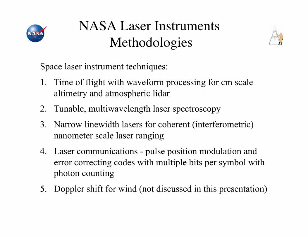
Space laser instrument techniques:
1. Time of flight with waveform processing for cm scale altimetry and atmospheric lidar
2. Tunable, multiwavelength laser spectroscopy
3. Narrow linewidth lasers for coherent (interferometric) nanometer scale laser ranging
4. Laser communications - pulse position modulation and error correcting codes with multiple bits per symbol with photon counting
5. Doppler shift for wind (not discussed in this presentation)
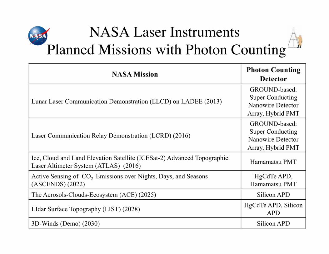
NASA Laser Instruments " Planned Missions with Photon Counting!
NASA Mission Photon Counting Detector
Lunar Laser Communication Demonstration (LLCD) on LADEE (2013)
GROUND-based: Super Conducting Nanowire Detector Array, Hybrid PMT
Laser Communication Relay Demonstration (LCRD) (2016)
GROUND-based: Super Conducting Nanowire Detector Array, Hybrid PMT
Ice, Cloud and Land Elevation Satellite (ICESat-2) Advanced Topographic Laser Altimeter System (ATLAS) (2016) Hamamatsu PMT
Active Sensing of CO2 Emissions over Nights, Days, and Seasons (ASCENDS) (2022)
HgCdTe APD, Hamamatsu PMT
The Aerosols-Clouds-Ecosystem (ACE) (2025) Silicon APD
LIdar Surface Topography (LIST) (2028) HgCdTe APD, Silicon APD
3D-Winds (Demo) (2030) Silicon APD
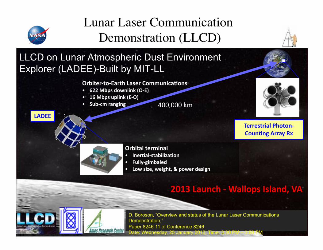
Lunar Laser Communication Demonstration (LLCD)!
!"#$%&"'%(')*"%+,-*.&",/(0012$3*4(2.,! 566,7#8.,9(:2;$2<,=!')>,
! ?5,7#8.,18;$2<,=)'!>,
! @1#'30,"*2A$2A,
-BC)),
!"#$%*;,%&"0$2*;,! D2&"4*;'.%*#$;$E*4(2,
! F1;;G'A$0#*;&9,,
! -(:,.$E&H,:&$A+%H,I,8(:&",9&.$A2,
J&""&.%"$*;,K+(%(2'
/(1242A,B""*G,LM,
6N?O,-*123+,',P*;;(8.,D.;*29H,QB,
LLCD on Lunar Atmospheric Dust Environment Explorer (LADEE)-Built by MIT-LL
"##$###%&'%
D. Boroson, “Overview and status of the Lunar Laser Communications Demonstration,” Paper 8246-11 of Conference 8246 Date: Wednesday, 25 January 2012; Time: 3:30 PM – 3:50 PM
Ground Track and Footprint
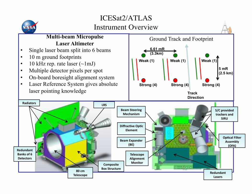
ICESat2/ATLAS "Instrument Overview!
Multi-beam Micropulse Laser Altimeter
• Single laser beam split into 6 beams • 10 m ground footprints • 10 kHz rep. rate laser (~1mJ) • Multiple detector pixels per spot • On-board boresight alignment system • Laser Reference System gives absolute
laser pointing knowledge Track Direction
5 mR (2.5 km)
6.61 mR (3.3km)
Weak (1)
Strong (4) Strong (4)
Weak (1)
Strong (4)
Weak (1)
/(08(.$%&,
R(M,@%"13%1"&
L*9$*%(".
SN,30,
J&;&.3(8&
@T/,8"(U$9&9,
%"*3<&".,*29,
@DLV,
-L@
R&*0,)M8*29&",
=R)>
C$W"*34U&,!843,
);&0&2% !843*;,F$;%&",
B..&0#;G,
=!FB>
L&9129*2%,
-*.&".
R&*0,@%&&"$2A,
7&3+*2$.0
L&9129*2%,
R*2<.,(X,5,,
C&%&3%(".,J&;&.3(8&,
B;$A20&2%,
7(2$%("
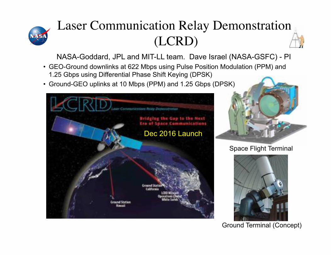
Space Flight Terminal
• GEO-Ground downlinks at 622 Mbps using Pulse Position Modulation (PPM) and 1.25 Gbps using Differential Phase Shift Keying (DPSK)
• Ground-GEO uplinks at 10 Mbps (PPM) and 1.25 Gbps (DPSK)
NASA-Goddard, JPL and MIT-LL team. Dave Israel (NASA-GSFC) - PI
Ground Terminal (Concept)
Dec 2016 Launch
Laser Communication Relay Demonstration (LCRD)!

Trace Gas Measurement for Earth & Planetary Sciences!
• Generation of high spatial resolution maps of trace gas !– Mars & earth applications!
• Laser-based measurement from orbits!• Replacing low-resolution passive spectrometers!
• Target trace gases!– Earth!
• CO2, CH4, etc. as greenhouse gases!• Absorptions at NIR wavelengths!
– Mars!• CH4, H2O, etc. as life indicators!• Absorptions at MIR wavelengths!
• Differential Absorption Lidar (DIAL)!– Receiver measures energy of the laser echoes from surface!
• On-line and off-line measurements!– Continuous global coverage!
• No need for sunlight!• OPA-based transmitter!
– 1064nm pulsed pump!– Tunable seed!– NIR/MIR outputs!
• Simpler than OPO!• Alternative to NIR fiber amp!
Seed laser
Fiber amplifier OPA
Pump laser
Transmitter
optics
()%*+,-./0%1020/3)4%-,)'%
*+,-./0%
Receiver optics
Detector & signal
processing electronics
!)4% !)5%
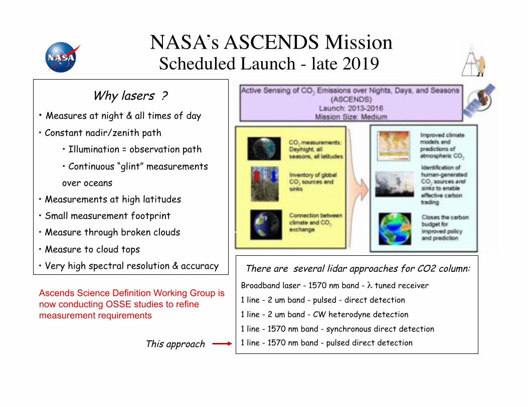
NASA’s ASCENDS Mission!Scheduled Launch - late 2019 !
Why lasers ?
• Measures at night & all times of day
• Constant nadir/zenith path
• Illumination = observation path
• Continuous “glint” measurements
over oceans
• Measurements at high latitudes
• Small measurement footprint
• Measure through broken clouds
• Measure to cloud tops
• Very high spectral resolution & accuracy There are several lidar approaches for CO2 column: Broadband laser - 1570 nm band - ! tuned receiver
1 line - 2 um band - pulsed - direct detection
1 line - 2 um band - CW heterodyne detection
1 line - 1570 nm band - synchronous direct detection 1 line - 1570 nm band - pulsed direct detection This approach
Ascends Science Definition Working Group is now conducting OSSE studies to refine measurement requirements
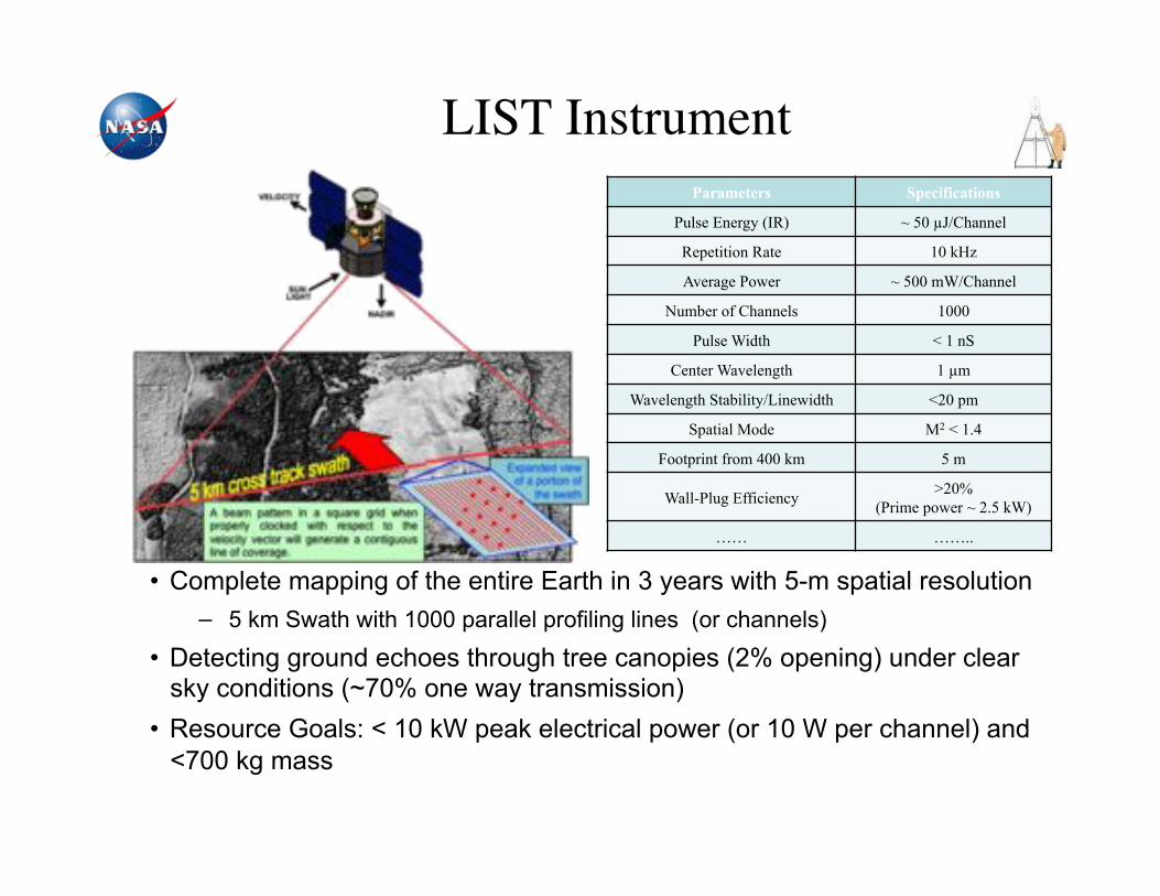
LIST Instrument!
• Complete mapping of the entire Earth in 3 years with 5-m spatial resolution − 5 km Swath with 1000 parallel profiling lines (or channels)
• Detecting ground echoes through tree canopies (2% opening) under clear sky conditions (~70% one way transmission)
• Resource Goals: < 10 kW peak electrical power (or 10 W per channel) and <700 kg mass
Parameters Specifications
Pulse Energy (IR) ~ 50 !J/Channel
Repetition Rate 10 kHz
Average Power ~ 500 mW/Channel
Number of Channels 1000
Pulse Width < 1 nS
Center Wavelength 1 !m
Wavelength Stability/Linewidth <20 pm
Spatial Mode M2 < 1.4
Footprint from 400 km 5 m
Wall-Plug Efficiency >20% (Prime power ~ 2.5 kW)
…… ……..

AGENDA!
I. NASA LASER INSTRUMENTS
II. DETECTOR REQUIREMENTS
III. CANDIDATE DETECTORS
IV. SUMMARY
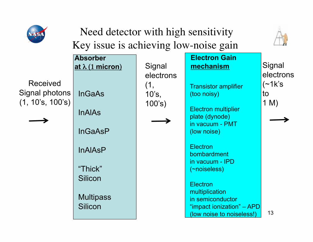
Need detector with high sensitivity "Key issue is achieving low-noise gain !
13
Received Signal photons (1, 10’s, 100’s)
Absorber at ! (1 micron)"
InGaAs
InAlAs
InGaAsP
InAlAsP
“Thick” Silicon
Multipass Silicon
Signal electrons (1, 10’s, 100’s)
Electron Gain mechanism"
Transistor amplifier (too noisy)
Electron multiplier plate (dynode) in vacuum - PMT (low noise)
Electron bombardment in vacuum - IPD (~noiseless)
Electron multiplication in semiconductor “impact ionization” – APD (low noise to noiseless!)
Signal electrons (~1k’s to 1 M)

NASA-GSFC Single-Photon Counting Detectors "
NASA Goals!
< 1% in 1 µs Afterpulsing
rugged, reliable, overlight protection Space-qualifiable :
prefer thermo-electric cooler range Operating temperature:
Highly desirable Resolves photon number:
< 200 ps Timing jitter: > 98% fit Linearity:
> 500 MHz Electrical bandwidth:
> 100 Mcps Maximum Count Rate: < 100 kcps Dark counts: . 1-D and 2-D arrays
> 200 µm diameter (n/a to array) Detector size: > 10% Detection efficiency: (Separate detectors) 0.3 - 4.0 µ m Photon counting wavelength range
AGENDA!
I. NASA LASER INSTRUMENTS
II. DETECTOR REQUIREMENTS
III. CANDIDATE DETECTORS
IV. SUMMARY

AGENDA!
III. CANDIDATE DETECTORS 1. Photomultipliers 2. Avalanche Photodiodes 3. Superconducting Nanowires (not
discussed)

AGENDA!
III. CANDIDATE DETECTORS 1. Photomultipliers 2. Avalanche Photodiodes 3. Superconducting Nanowires (not
discussed)
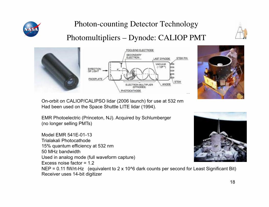
Photon-counting Detector Technology"
Photomultipliers – Dynode: CALIOP PMT"
18
On-orbit on CALIOP/CALIPSO lidar (2006 launch) for use at 532 nm Had been used on the Space Shuttle LITE lidar (1994).
EMR Photoelectric (Princeton, NJ). Acquired by Schlumberger (no longer selling PMTs)
Model EMR 541E-01-13 Trialakali Photocathode 15% quantum efficiency at 532 nm 50 MHz bandwidth Used in analog mode (full waveform capture) Excess noise factor = 1.2 NEP = 0.11 fW/rt-Hz (equivalent to 2 x 10^6 dark counts per second for Least Significant Bit) Receiver uses 14-bit digitizer
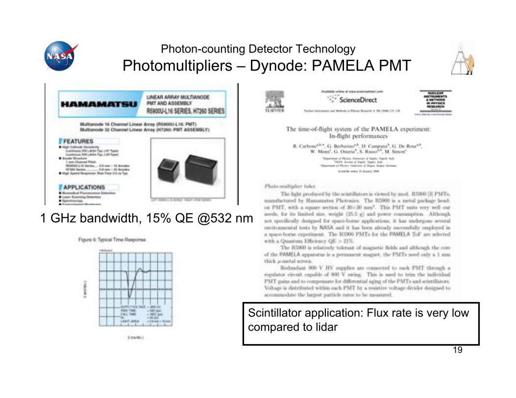
Photon-counting Detector Technology Photomultipliers – Dynode: PAMELA PMT
19
Scintillator application: Flux rate is very low compared to lidar
1 GHz bandwidth, 15% QE @532 nm
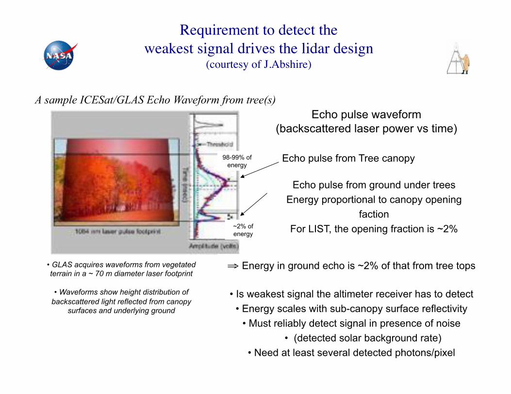
A sample ICESat/GLAS Echo Waveform from tree(s)
• GLAS acquires waveforms from vegetated terrain in a ~ 70 m diameter laser footprint
• Waveforms show height distribution of backscattered light reflected from canopy
surfaces and underlying ground
Echo pulse from ground under trees Energy proportional to canopy opening
faction For LIST, the opening fraction is ~2%
Echo pulse from Tree canopy
Echo pulse waveform (backscattered laser power vs time)
# Energy in ground echo is ~2% of that from tree tops
• Is weakest signal the altimeter receiver has to detect • Energy scales with sub-canopy surface reflectivity
• Must reliably detect signal in presence of noise • (detected solar background rate)
• Need at least several detected photons/pixel
98-99% of energy
~2% of energy
Requirement to detect the "weakest signal drives the lidar design "
(courtesy of J.Abshire) "
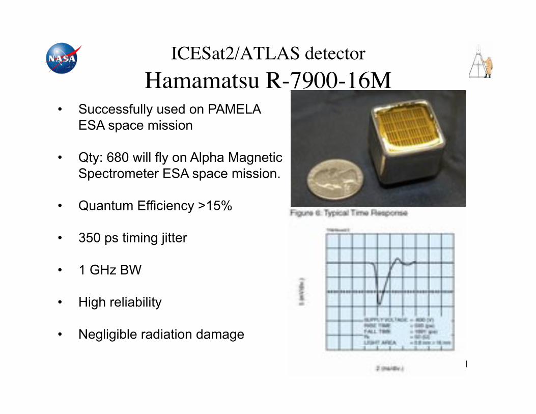
ICESat2/ATLAS detector "Hamamatsu R-7900-16M!
21
• Successfully used on PAMELA ESA space mission
• Qty: 680 will fly on Alpha Magnetic Spectrometer ESA space mission.
• Quantum Efficiency >15%
• 350 ps timing jitter
• 1 GHz BW
• High reliability
• Negligible radiation damage
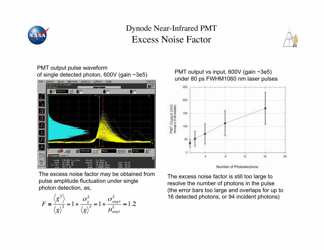
Dynode Near-Infrared PMT"Excess Noise Factor!
PMT output pulse waveform of single detected photon, 600V (gain ~3e5) PMT output vs input, 600V (gain ~3e5)
under 80 ps FWHM1060 nm laser pulses
The excess noise factor may be obtained from pulse amplitude fluctuation under single photon detection, as,
The excess noise factor is still too large to resolve the number of photons in the pulse (the error bars too large and overlaps for up to 16 detected photons, or 94 incident photons)
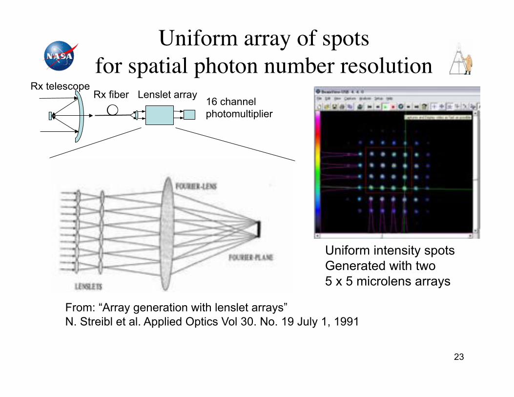
Uniform array of spots "for spatial photon number resolution!
23
From: “Array generation with lenslet arrays” N. Streibl et al. Applied Optics Vol 30. No. 19 July 1, 1991
Uniform intensity spots Generated with two 5 x 5 microlens arrays
Rx telescope 16 channel photomultiplier
Rx fiber Lenslet array
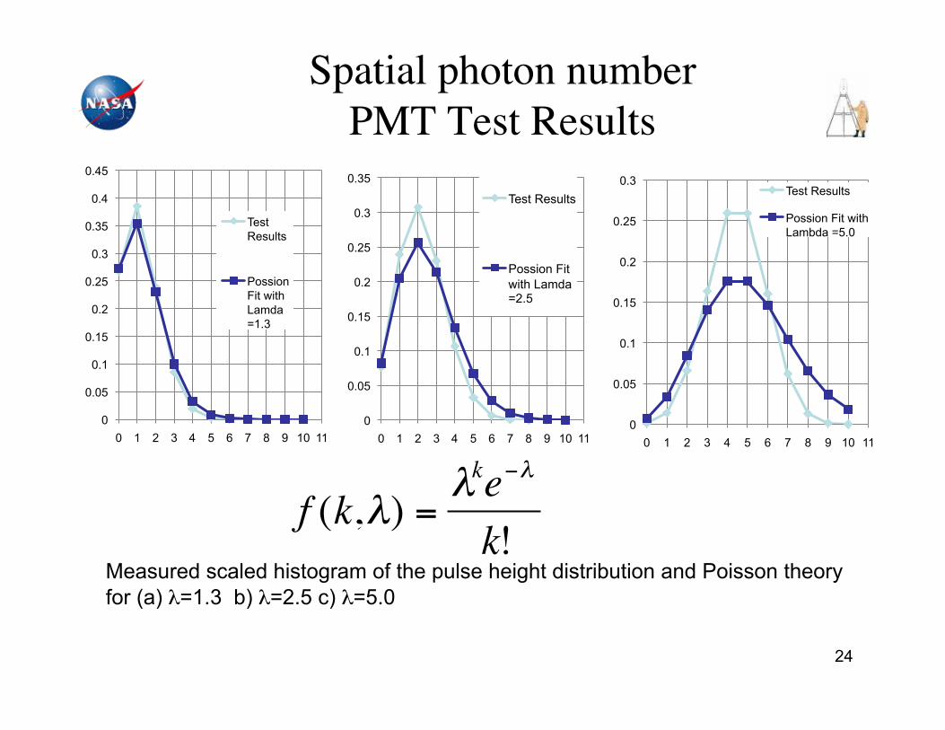
Spatial photon number"PMT Test Results!
24
0
0.05
0.1
0.15
0.2
0.25
0.3
0 1 2 3 4 5 6 7 8 9 10 11
Test Results
Possion Fit with Lambda =5.0
!
f (k,") ="ke#"
k!Measured scaled histogram of the pulse height distribution and Poisson theory for (a) !=1.3 b) !=2.5 c) !=5.0
0
0.05
0.1
0.15
0.2
0.25
0.3
0.35
0 1 2 3 4 5 6 7 8 9 10 11
Test Results
Possion Fit with Lamda =2.5
0
0.05
0.1
0.15
0.2
0.25
0.3
0.35
0.4
0.45
0 1 2 3 4 5 6 7 8 9 10 11
Test Results
Possion Fit with Lamda =1.3
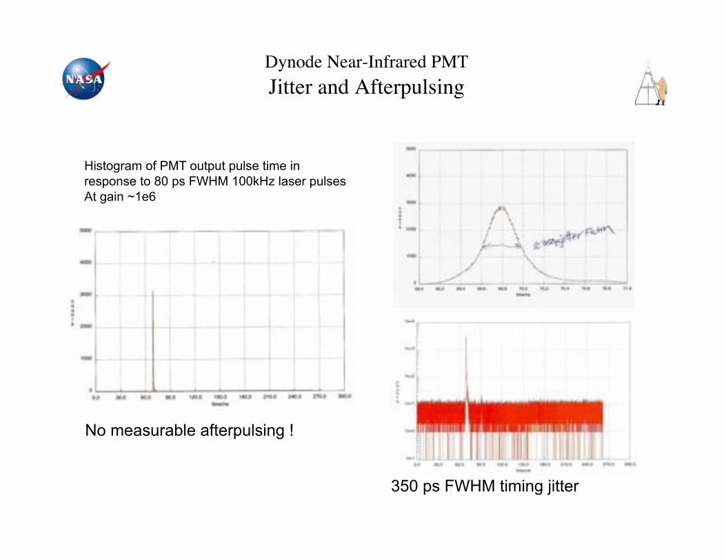
Dynode Near-Infrared PMT"Jitter and Afterpulsing!
Histogram of PMT output pulse time in response to 80 ps FWHM 100kHz laser pulses At gain ~1e6
No measurable afterpulsing !
350 ps FWHM timing jitter

Photon-counting Detector Technology Photomultipliers – Micro Channel Plate
26
Very low timing jitter (<100 ps)
> 1 GHz bandwidth
35% QE @532 nm
Multi-anode (100 pixels) version available Model R4110U
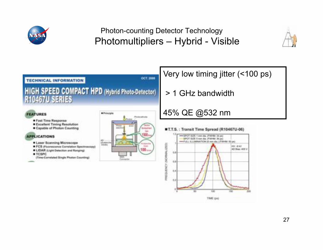
Photon-counting Detector Technology Photomultipliers – Hybrid - Visible
27
Very low timing jitter (<100 ps)
> 1 GHz bandwidth
45% QE @532 nm

Photon-counting Detector Technology "Photomultipliers – Dynode: Near infrared PMT!
• Hamamatsu NIR-PMT 10330-75, s/n BB0085 near infrared photomultiplier tube. “Champion” device.
• 18% quantum efficiency: 0.9 to 1.55 um wavelength.
HV supply and PMT housing
TO-8 PMT package with transmissive photocathode
H10330-75 TEC cooled with no vacuum pump!
Photon Detection Efficiency ~17% (highest to date) at 1550 nm

29
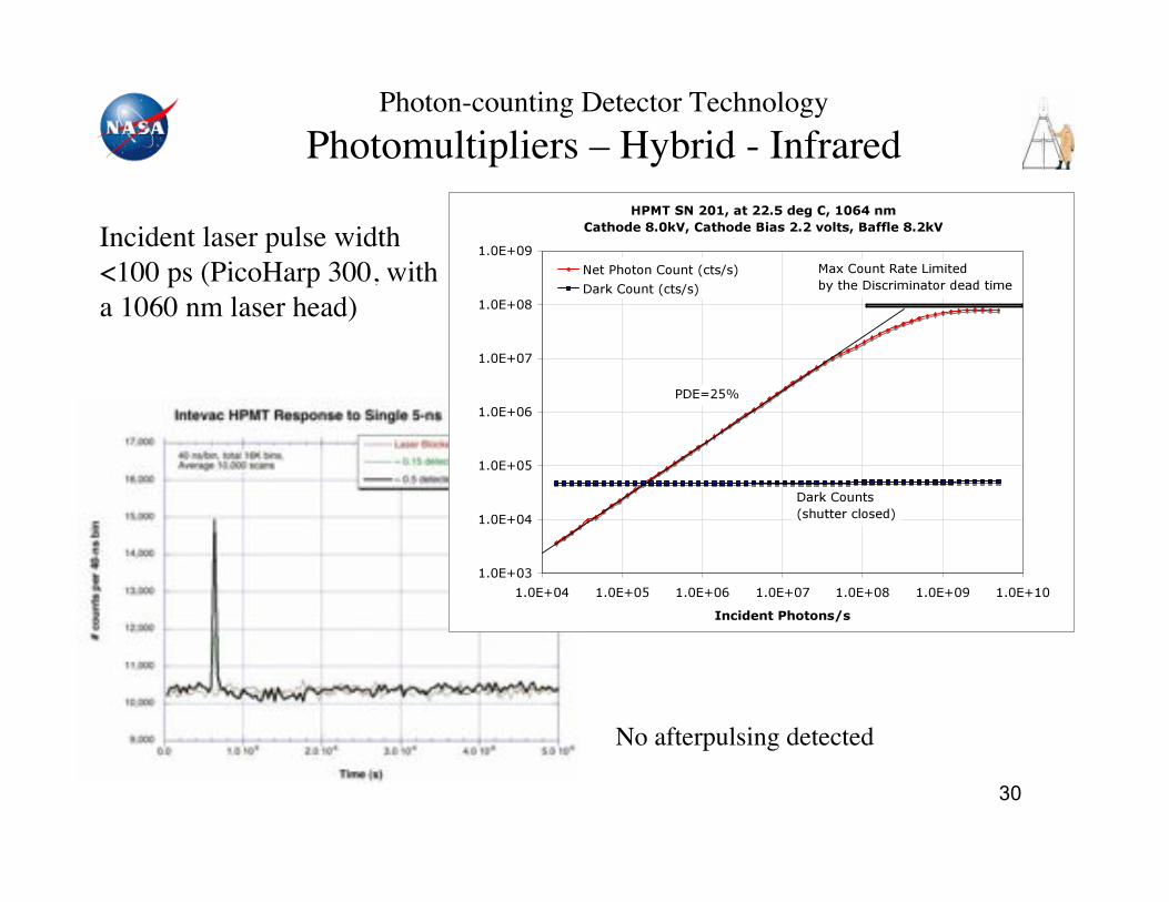
Photon-counting Detector Technology"Photomultipliers – Hybrid - Infrared!
• Transfer electron (TE) photocathode – InGaAsP for 1000-1300 nm – InGaAs for 1000-1600 nm
(higher dark count rates) – PMTs with similar photocathode
have been commercially available and the performance has been improving.
• GaAs Schottky APD anode for low timing jitter and wide electrical bandwidth (~1GHz).
• HPMTs with TE photocathodes >25% QE at 1064 nm
>15% QE at 1550 nm InGaAsP HPMT from Intevac Inc.!
30
Photon-counting Detector Technology"Photomultipliers – Hybrid - Infrared!
Incident laser pulse width <100 ps (PicoHarp 300, with a 1060 nm laser head)!
No afterpulsing detected!

Single-photon timing jitter per pixel measurement!
31
Results for IPD with thinner (0.8 µm) InGaAsP layer thickness.
FWHM = 188 ps.
Dashed line is Gaussian fit with $ = 78 ps.
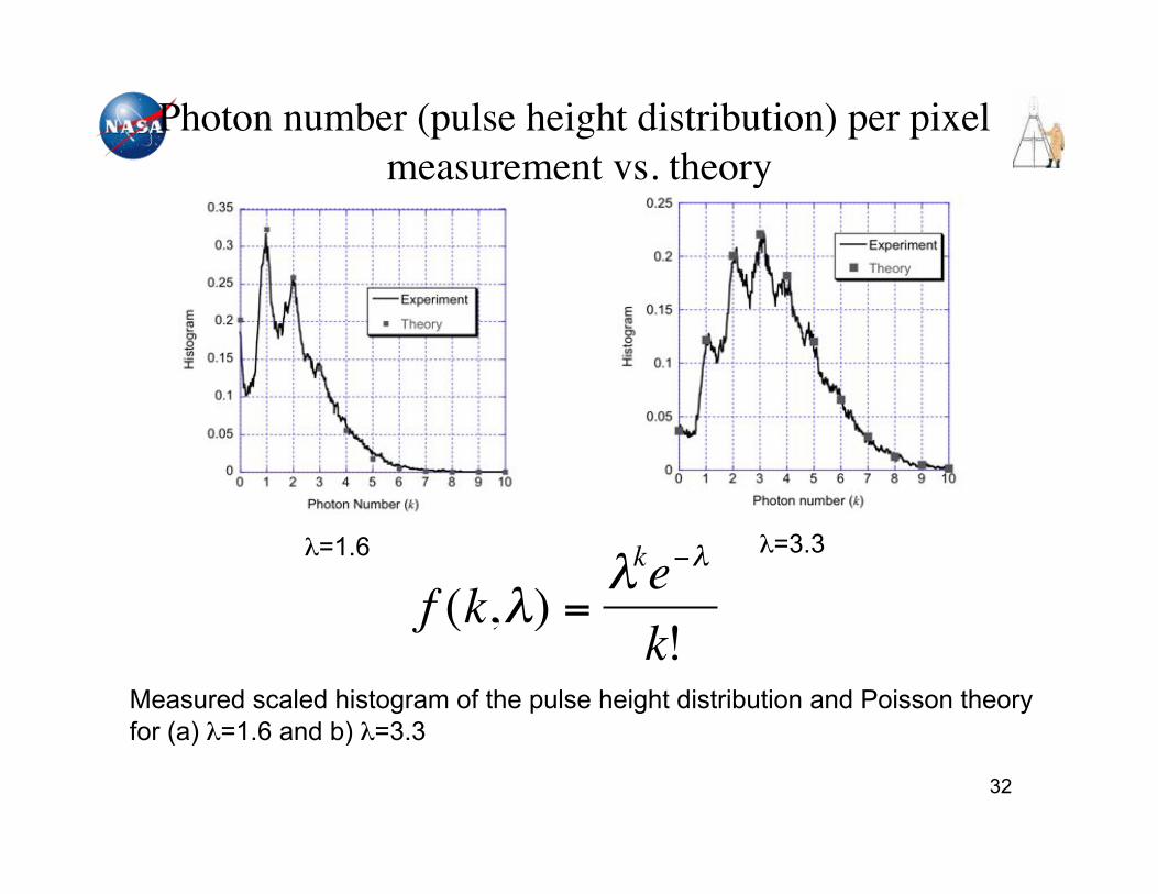
Photon number (pulse height distribution) per pixel measurement vs. theory!
32
Measured scaled histogram of the pulse height distribution and Poisson theory for (a) !=1.6 and b) !=3.3
!
f (k,") ="ke#"
k!
!=1.6 !=3.3
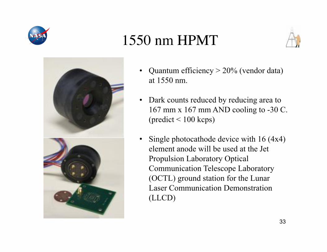
33
1550 nm HPMT!
• Quantum efficiency > 20% (vendor data) at 1550 nm.
• Dark counts reduced by reducing area to 167 mm x 167 mm AND cooling to -30 C.
(predict < 100 kcps)
• Single photocathode device with 16 (4x4) element anode will be used at the Jet Propulsion Laboratory Optical Communication Telescope Laboratory (OCTL) ground station for the Lunar Laser Communication Demonstration (LLCD)

34
NASA-GSFC Single-Photon Counting Detectors "
NASA Goals ! HPMT/PMT
AGENDA!
III. CANDIDATE DETECTORS 1. Photomultipliers 2. Avalanche Photodiodes 3. Superconducting Nanowires (not
discussed)
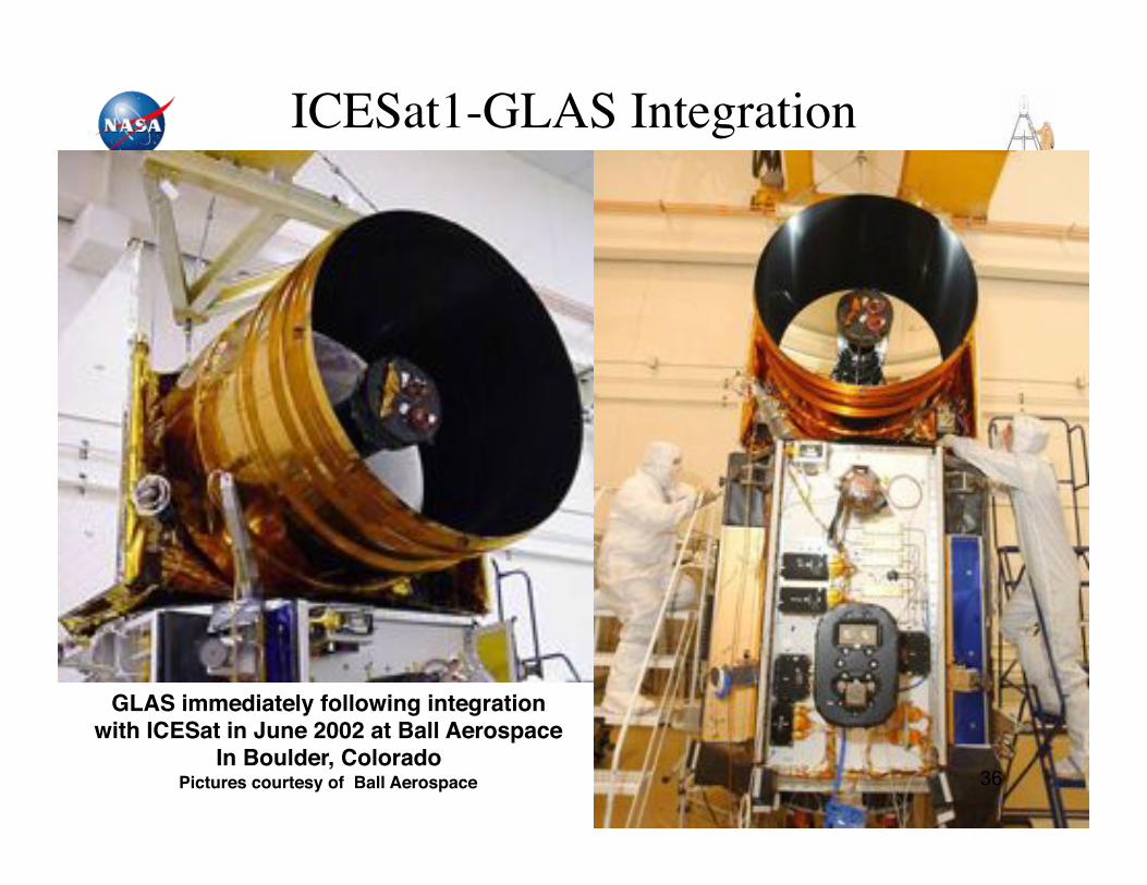
GLAS immediately following integration!with ICESat in June 2002 at Ball Aerospace!
In Boulder, Colorado!Pictures courtesy of Ball Aerospace
ICESat1-GLAS Integration!
36
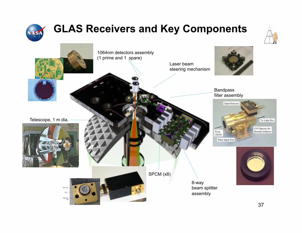
1064nm detectors assembly (1 prime and 1 spare)
Laser beam steering mechanism
SPCM (x8)
Bandpass filter assembly
8-way beam splitter assembly
Telescope, 1 m dia.
GLAS Receivers and Key Components
37

Perkin Elmer SPCM
Detection efficiency > 6% at 1064 nm, > 8% at 1030 nm 38
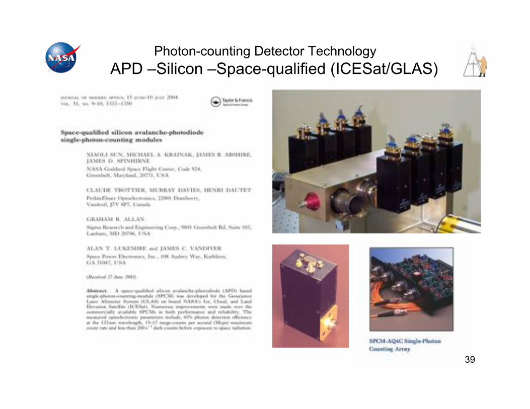
Photon-counting Detector Technology APD –Silicon –Space-qualified (ICESat/GLAS)
39
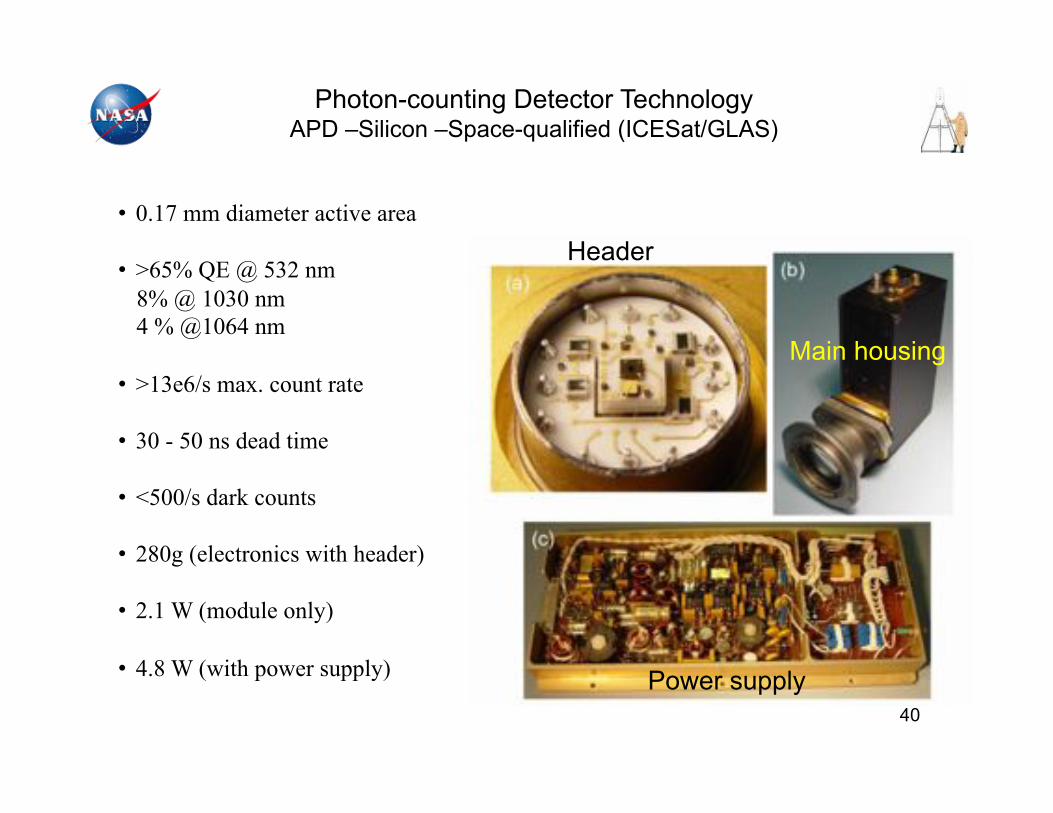
Photon-counting Detector Technology APD –Silicon –Space-qualified (ICESat/GLAS)
• 0.17 mm diameter active area
• >65% QE @ 532 nm 8% @ 1030 nm 4 % @1064 nm
• >13e6/s max. count rate
• 30 - 50 ns dead time
• <500/s dark counts
• 280g (electronics with header)
• 2.1 W (module only)
• 4.8 W (with power supply)
Header
Main housing
Power supply 40
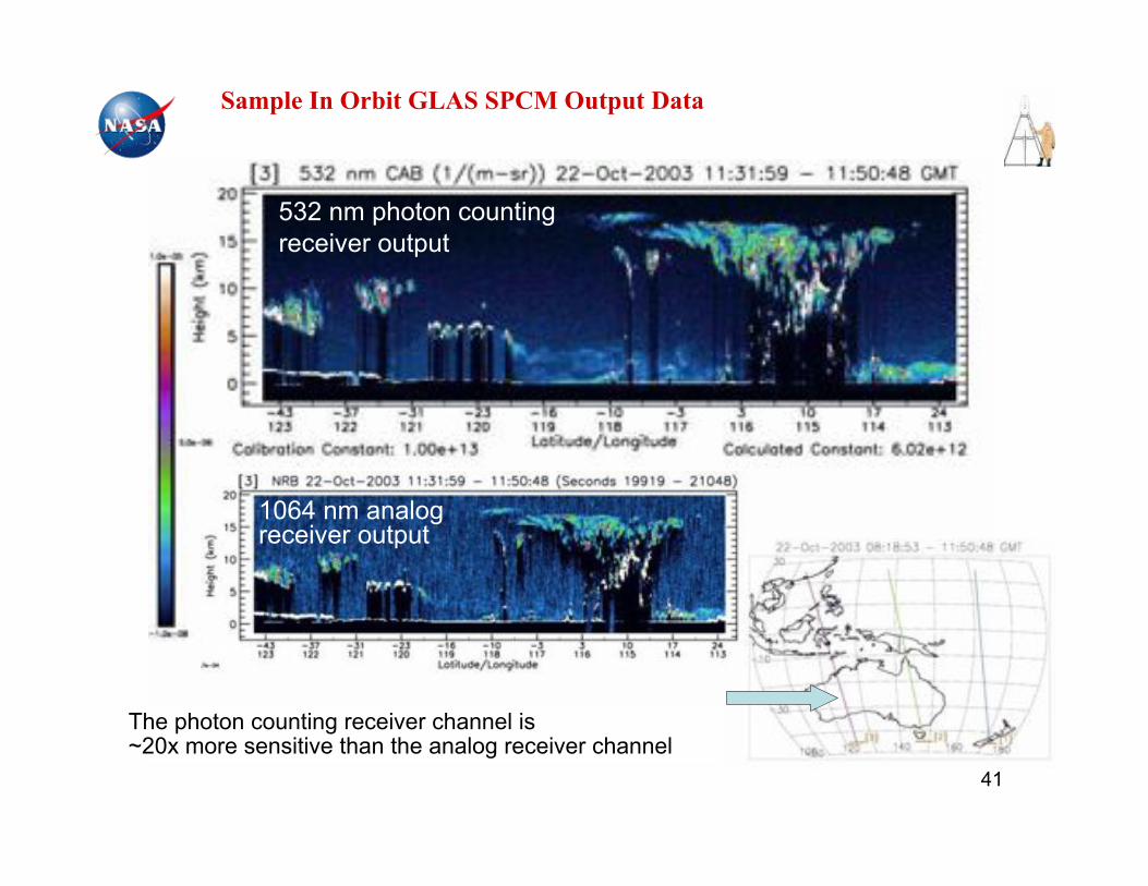
Sample In Orbit GLAS SPCM Output Data
The photon counting receiver channel is ~20x more sensitive than the analog receiver channel
532 nm photon counting receiver output
1064 nm analog receiver output
41
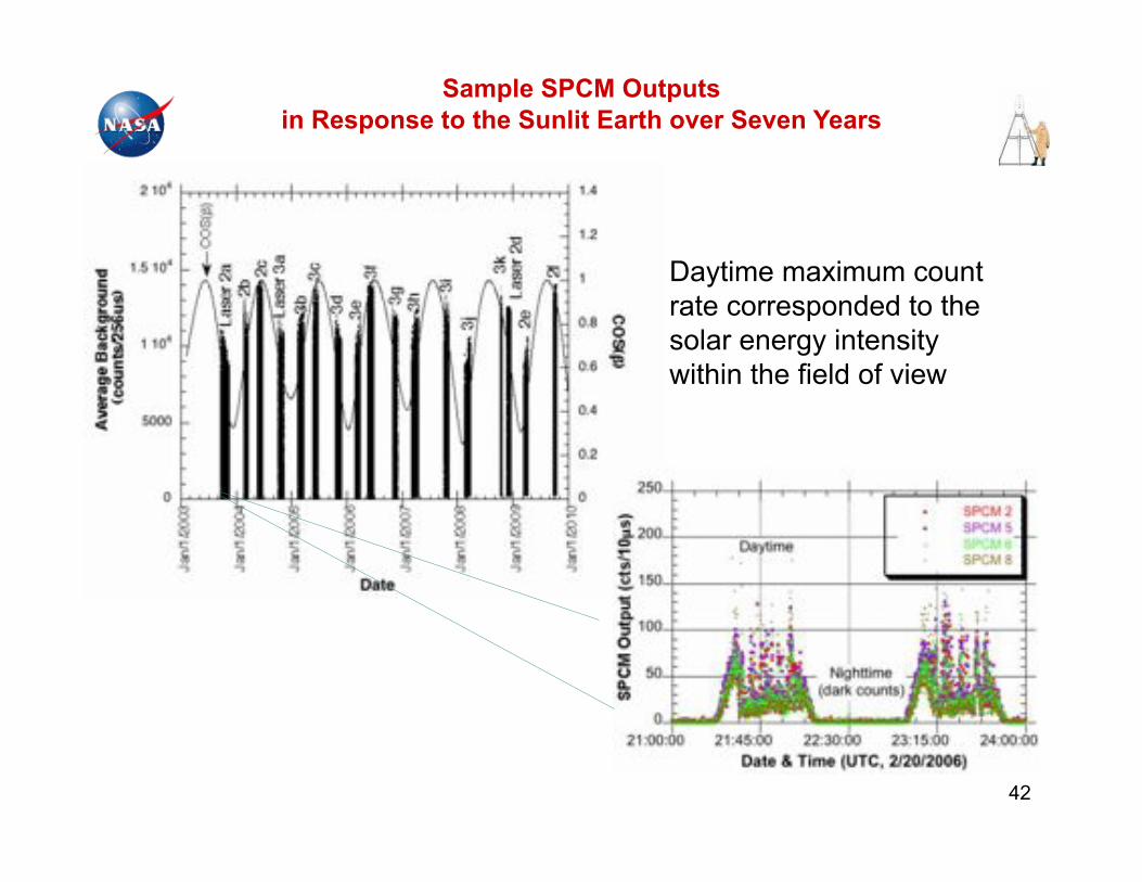
Daytime maximum count rate corresponded to the solar energy intensity within the field of view
Sample SPCM Outputs in Response to the Sunlit Earth over Seven Years
42
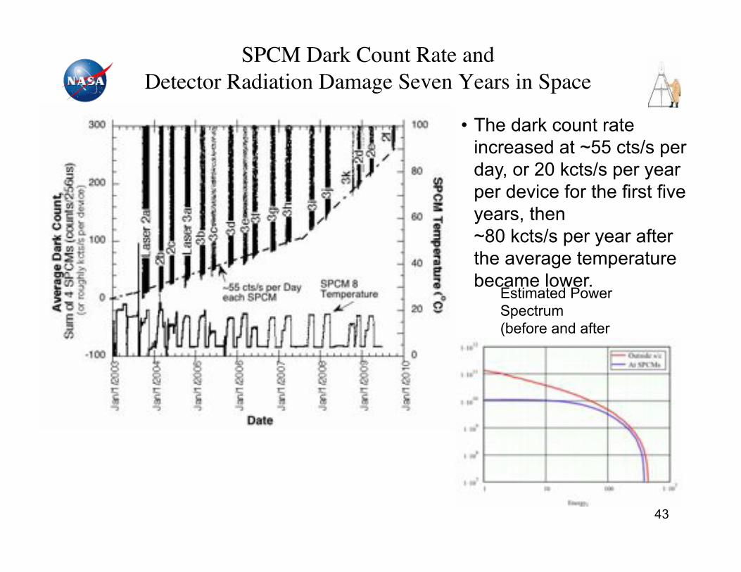
SPCM Dark Count Rate and "Detector Radiation Damage Seven Years in Space!
• The dark count rate increased at ~55 cts/s per day, or 20 kcts/s per year per device for the first five years, then ~80 kcts/s per year after the average temperature became lower.
Estimated Power Spectrum (before and after shielding for a 3 years mission time)
43
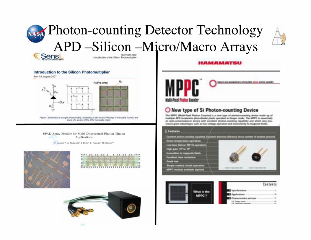
Photon-counting Detector Technology"APD –Silicon –Micro/Macro Arrays!

Photon-counting Detector Technology APD –InGaAs(P)/InP –Arrays
45
Packaged 32x32 InGaAs APD array on readout IC, with microlens array, on TE cooler inside package
8 x 8 InGaAs NFAD matrix
Boeing/Spectrolab Princeton Lightwave
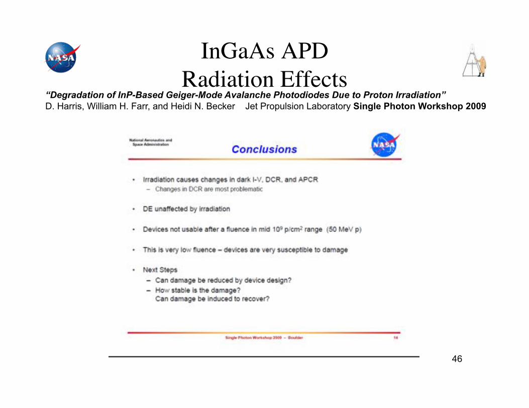
InGaAs APD "Radiation Effects!
46
“Degradation of InP-Based Geiger-Mode Avalanche Photodiodes Due to Proton Irradiation” D. Harris, William H. Farr, and Heidi N. Becker Jet Propulsion Laboratory Single Photon Workshop 2009
47
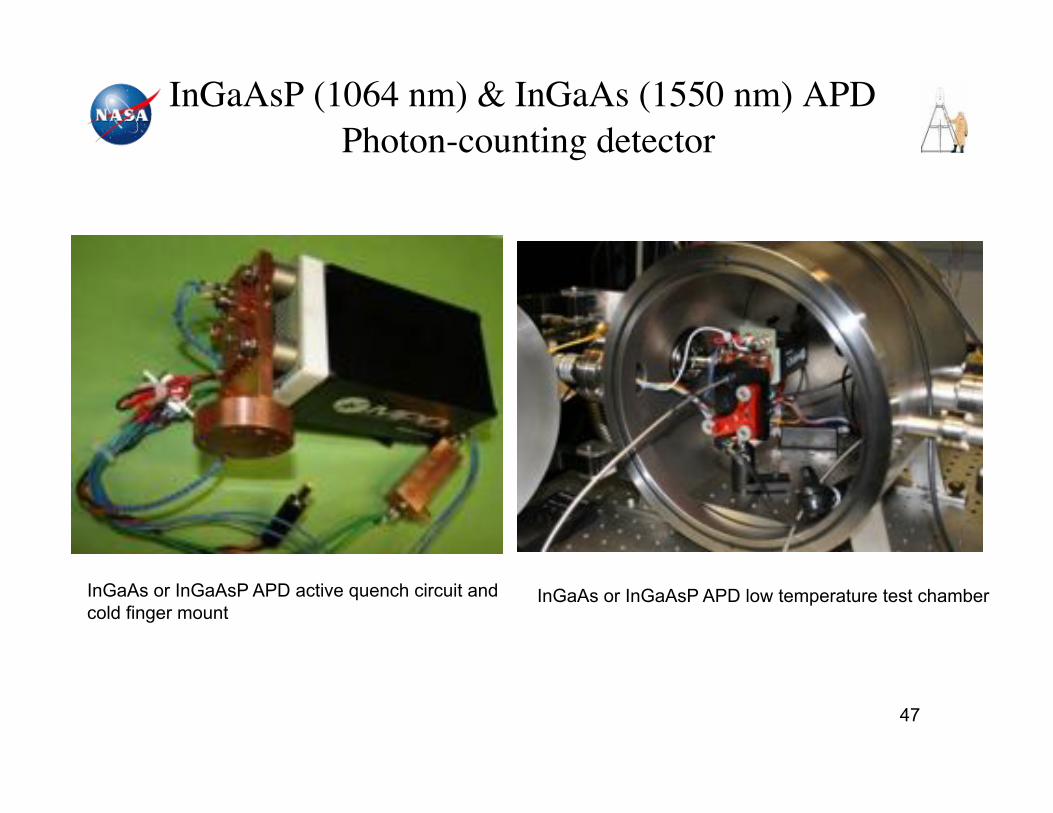
InGaAsP (1064 nm) & InGaAs (1550 nm) APD "Photon-counting detector!
InGaAs or InGaAsP APD active quench circuit and cold finger mount
InGaAs or InGaAsP APD low temperature test chamber
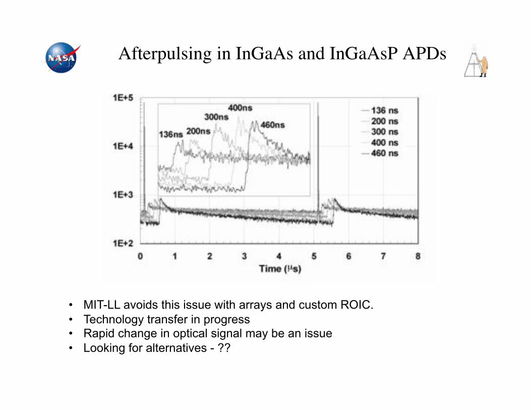
Afterpulsing in InGaAs and InGaAsP APDs!
• MIT-LL avoids this issue with arrays and custom ROIC. • Technology transfer in progress • Rapid change in optical signal may be an issue • Looking for alternatives - ??
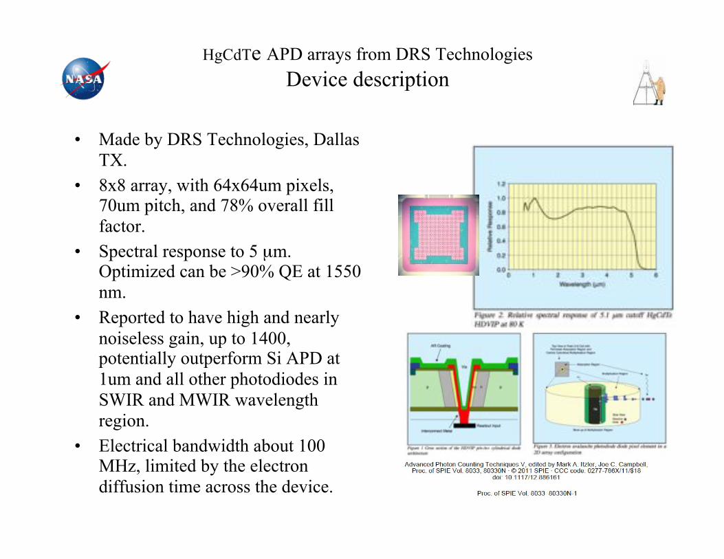
HgCdTe APD arrays from DRS Technologies Device description
• Made by DRS Technologies, Dallas TX.
• 8x8 array, with 64x64um pixels, 70um pitch, and 78% overall fill factor.
• Spectral response to 5 µm. Optimized can be >90% QE at 1550 nm.
• Reported to have high and nearly noiseless gain, up to 1400, potentially outperform Si APD at 1um and all other photodiodes in SWIR and MWIR wavelength region.
• Electrical bandwidth about 100 MHz, limited by the electron diffusion time across the device.
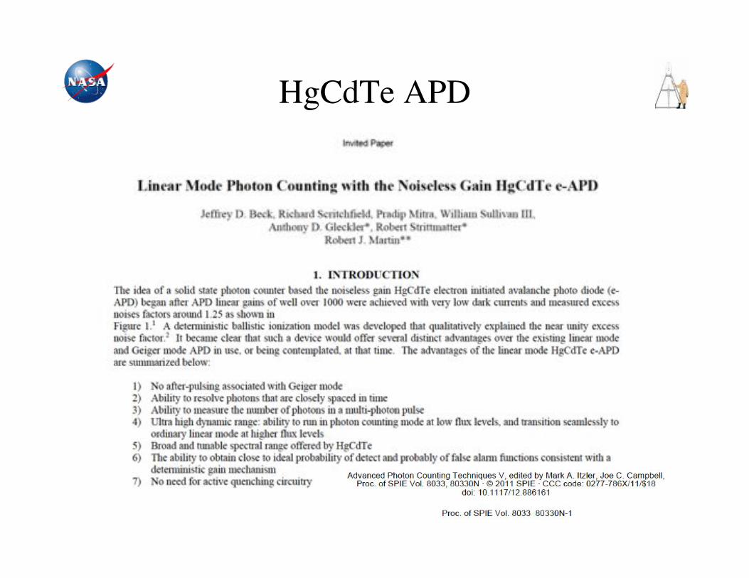
HgCdTe APD!

AGENDA!
I. NASA LASER INSTRUMENTS
II. DETECTOR REQUIREMENTS
III. CANDIDATE DETECTORS
IV. SUMMARY
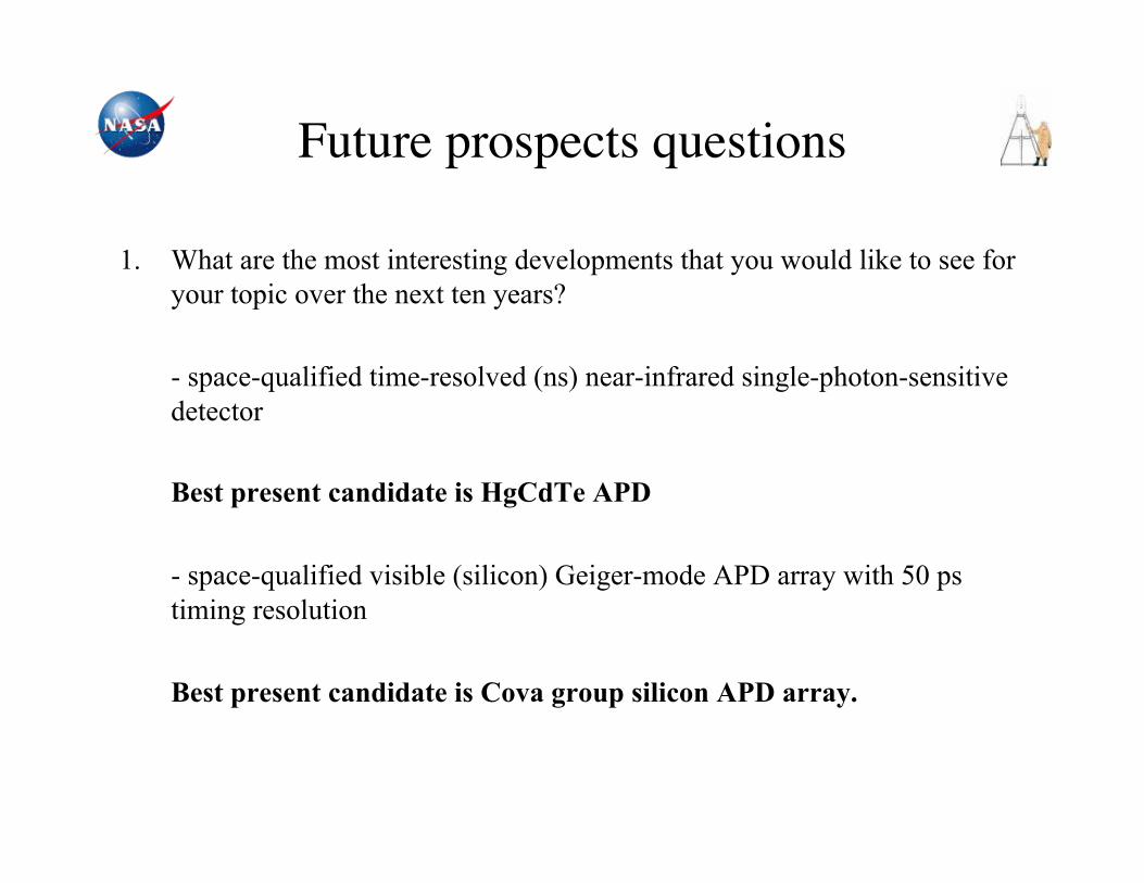
Future prospects questions!
1. What are the most interesting developments that you would like to see for your topic over the next ten years?
- space-qualified time-resolved (ns) near-infrared single-photon-sensitive detector
Best present candidate is HgCdTe APD
- space-qualified visible (silicon) Geiger-mode APD array with 50 ps timing resolution
Best present candidate is Cova group silicon APD array.

Future prospects questions!
2. What are the biggest challenges for developing relevant technology over the next ten years?
- consistent funding - material engineering
3. What science breakthroughs could be enabled by this technology over the next ten years?
- global earth-atmosphere trace-gas (CO2, CH4, etc.) measurements - global Mars atmosphere trace-gas (H2O, CH4, etc.) measurements - diffuse optical tomography of the human brain for perfusion etc.
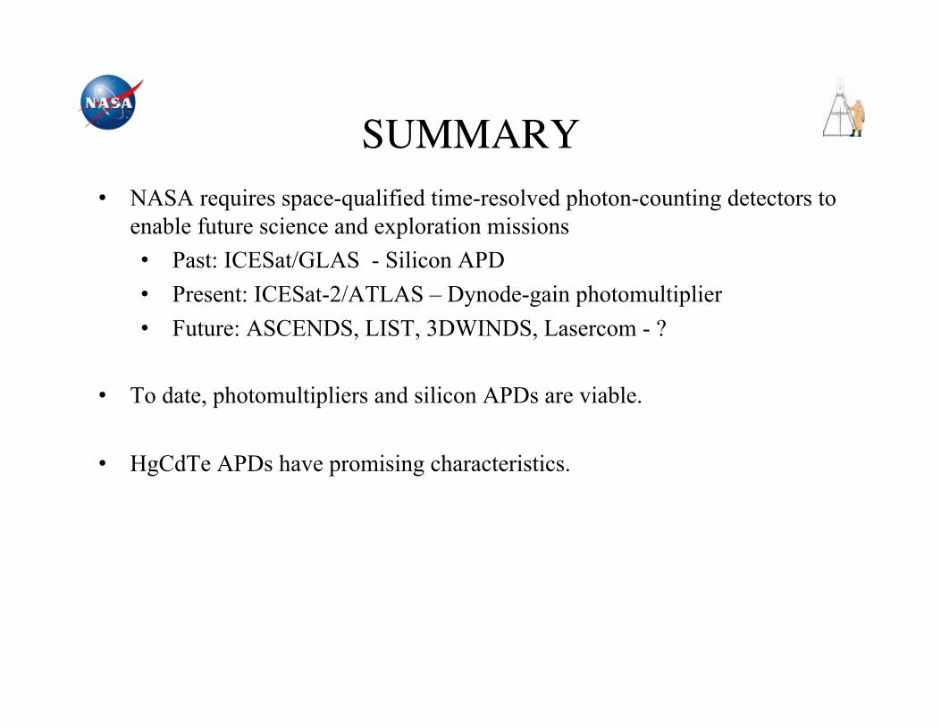
SUMMARY!• NASA requires space-qualified time-resolved photon-counting detectors to
enable future science and exploration missions • Past: ICESat/GLAS - Silicon APD • Present: ICESat-2/ATLAS – Dynode-gain photomultiplier • Future: ASCENDS, LIST, 3DWINDS, Lasercom - ?
• To date, photomultipliers and silicon APDs are viable.
• HgCdTe APDs have promising characteristics.
Acknowledgement!
The authors would like to thank
NASA ESTO;
NASA ASTID program;
GSFC IRAD program;
GSFC SBIR program
and the
Instrument and Science Teams of:
MOLA, ICESat/GLAS, Calipso, MLA, LOLA, ICESat-2, LIST SDT,
ASCENDS, GRACE-FO, GRACE-II, LADEE, LLCD & LCRD!
Recommended