ELSEVIER Surface and Coatings Technology 98 ( 1998) 1221-1227
SURfACE&COA11NIiS
IEGHNO/DGY
Ceramic thermal barrier coatings deposited with the electronbeam-physical vapour deposition technique
E. Lugscheider *, C. Barimani, G. DapperRheinisch- Westfalische Technische Hochschule Aachen, Lehr- und Forschungsgebiet Werkstoffwissenschaften.
Augustinerbach 4-22. 52056 Aachen, Germany
Abstract
The deposition of ceramic thermal barrier coatings for high-temperature applications is of great interest. Particularly when thethermal stresses are superimposed by mechanical stresses, the metallic base material will expand much more than the ceramic toplayer, so that the coating is not able to withstand the interfacial stresses and will spall off. Therefore such ceramic coatings shouldhave a special type of microstructure to ensure that the complete system can fulfil the desired properties, e.g. thermal shockresistance. By physical vapour deposition (PVD) techniques the microstructure of coatings can be adapted with respect to theseveral applications. The electron beam (EB)-PVD technique is particularly suitable for the deposition of thermal barrier coatings(TBC), owing to the relatively high deposition rate and the possibility of influencing the microstructure of the coating. The energyof the condensing film varies depending on the temperature of the substrate. It is known that the mobility of the adatom increaseswithin increasing temperature, so long as there is no adatom reflection at a too hot surface. In this paper the connection betweenthe method of heating the substrates during deposition and the resulting microstructure of the coatings is investigated. The aimis to achieve coatings of a columnar microstructure with a thickness of about 200 1JlIl, using the EB-PVD technique to depositpartially stabilized zirconia. Two different types of heat source are investigated, an indirect one using a resistance heater and adirect one using an electron beam. The other deposition parameters such as apparatus geometric, deposition rate, substratetemperature, gas pressure, etc., were kept constant. For both substrate heating methodes the temperature is measured bythermocouples. The type of heating source appears to play an important role, because different coating microstructures and thusvarious surface temperatures are obtained while measuring the same temperature at the back of the samples. Determination ofdifferent surface excitation, which obviously depends on the type of heating source. is also discussed. Some additional investigationsare in progress to confirm the observations. © 1998 Elsevier Science SA.
Keywords: Electron beam-physical vapour deposition; Thermal barrier coatings; Columnar microstructure; Substrate heatingmethodes; Gas turbines; Energy converting machines
1. Introduction
The reduction of environmental pollution and conser•vation of energy as well as economic aspects are of greatinterest for aircraft and power generation industries.This is related to increasing the lifetime of parts in thehot section of gas turbines while increasing the gas inlettemperature [I]. One possible way to achieve these aimsis the coating of the hot section parts with thermalbarrier coatings (TBC). In combination with internalcooling of these parts the ceramic top layer acts like athermal barrier [2].
Different coating processes are used to deposit suchceramic TBC. A coating technique showing high poten-
• Corresponding author. Tel: 49 241 805329; Fax: 49 241 888264.
0257-8972/98/$19.00 © 1998 Elsevier Science SA All rights reserved.PII S0257·8972(97)00149-7
tial for coatings on rotating turbine parts is the electronbeam-physical vapour deposition (EB-PVD) [3].EB-PVD TBC show very good behaviour in thermalcycling with up to ten times more cycles than coatingsdeposited with other techniques [4.5]. This is due to thestrain-tolerant columnar structure of the EB-PVD coat•ings [I], which enables them to be adapted to the desiredapplication. One of the problems related to the EB-PVDtechnique is the reproducibility of the TBC and thecoating of large machine parts [6], although this tech•nique in some cases is used as an industrial coatingprocess. There is a need for research and developmentin this area.
This presentation deals with different methods ofheating the substrates during the deposition process andthe resulting microstructure and properties of the TBC.Two heating methods are compared: the electron beam
1222 E. LIIK-"'hdt/er £'1111. 5I1rli/('(' ({nd Co({lings !"dll1ology 9S ( N9S! 1221 1227
0,. N2etc.¢
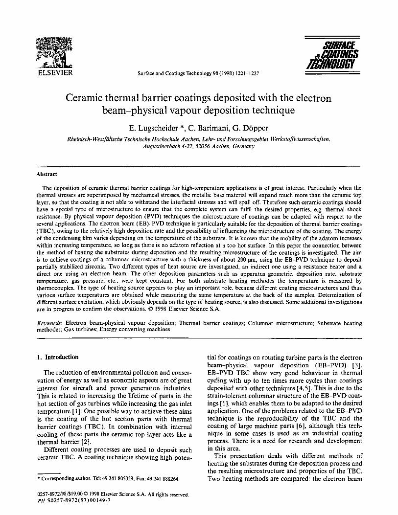
1 vacuum chamber2 radiation heater3 electron beam gun4 rotating crucible5 substrate6 evaporated particles7 gas inlet8 diffusion pump with baffle9 valve10 rough vacuum pump
1 vacuum chamber2 electron beam gun (substrate heating)3 electron beam evaporation unit4 rotating crucible5 substrate6 evaporated particles7 gas inlet8 diffusion pump with baffle9 valve10 rough vacuum pump
\7····6
5
0,. N,elc,
m---t:;:::::1 , ¢...-2
3
4
8......
9 ..... "--"'"'"rl.......
10--•(bl
Fig, I. EB PVD plant with (a) radiation heating system; (b) electron beam heating system,
gun as a direct and a radiation heater as an indirectheating source. All other deposition parameters werekept constant. The resulting microstructures were inves•tigated and compared by scanning electron microscopy(SEM). The type of heating source appears to play animportant role in surface temperature and excitation.The observations and suggested physical processesduring substrate heating are also discussed.
2. Experimental
Both methods of heating the substrates. directly byusing an electron beam gun and indirectly by radiationheating, were carried out in the same EB-PVD plant,and most parameters, e.g. apparatus geometry andevaporation of powders instead of ingots, could there•fore be kept constant. The principle of the two substrateheating methods is shown in Fig. I. As can be seen. aradiation heating system can only be arranged on theopposite side to that facing the crucible. This arrange•ment was first realized in the EB-PVD plant (Fig. la).Hot filaments were fixed in a holder which was formedin a semicircular way to enhance heat transfer by
radiation. The temperature was measured by a thermo•couple positioned at the same level beside the substrateand in contact with it. Heating the substrates had to bedone over a definite period to ensure warming of thecomplete substrate. Since problems occurred with thereproducibility and required temperature ranges, a deci•sion was taken to replace the radiation heating systemwith an electron beam gun as a direct heater.
After some extensive alterations, the EB-PVD systemhas now two electron bcam guns, both equipped withindependent evacuation systems (Fig. Ib). The gun,which was formerly used for evaporation, is now usedas the substrate heater. Whereas the radiation heatertook effect on the opposite side of the coated surface,the electrons of the electron bcam gun used for substrateheating are now directly effective on the surface of thesubstrate to be coated. Replacing the previous coppercrucible, a compact electron beam evaporation unit witha smaller copper crucible but the same power data wasinstalled. As a first stcp a powder feeding system had tobe developed for a continuous supply of evaporationmaterial, since the new copper crucible was too smalland it was not possible to fit in enough evaporationmaterial to achieve thick coatings. The temperature was
!
E. Lugscheider et al. / Surface and Coatings Technology 98 (1998) 1221-1227
incident electron beam
! ! !!!!!!!!! ! !Po(r}
1223
/ surface/
/ 2r/dEB
substrate
zlS
PA(z,r)/PAIM. T(z,r,t)fT....(t}Po = IEBUEB
S« dEB
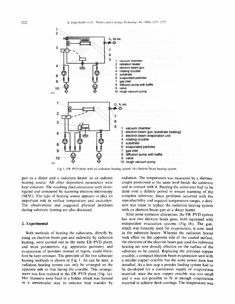
T =temperaturePo = maximum of incident powerPAlM. = maximum of absorbed powerPA= absorbed powerz = depth coordinateS = penetration depthr =radial coordinatedEB =lateral correction value
UEB =voltage of electron beamIEB = current of electron beam
Fig. 2. Power distribution inside an electron beam-heated substrate [7].
also measured by a thermocouple arranged on the backsurface of the heated substrate. This arrangement wasessential because of the smaller volume of the thermo•couple compared with the substrate, which resulted instronger heating of the thermocouple. Therefore, norealistic temperature could be measured when the ther•mocouple was not shielded against the heating electrons.
For a comparison of the resulting microstructure ofthe coatings using the two types of heating system, mostof the parameters could be kept constant, i.e. apparatusgeometry, distance between the crucible and substrate,reactive gas pressure (oxygen had to be added duringdeposition of zirconia), deposition rate, coating thick•ness, evaporation material (powder), type of temper•ature measurement and range of substrate temperature.As will be seen later on, there were differences in themicrostructures as well as the type of substrate heating.
3. Results and discussion
The two methods of substrate heating produced com•pletely different effects. In the case of radiant heatingsystems, heat transfer occurs only via thermal radiationfrom the outside, whereas direct heating by an electronbeam generates a source of heat inside the substrate.The absorbed energy of the electrons is transformedinto heat. forming a temperature profile inside thesubstrate. Fig. 2 shows the energy and power distribu•tion inside a substrate under the conditions of anelectron beam directed normal to the substrate's surfaceand with a rotationally symmetrical power densityhaving an effect on a lateral endless extended substrate,similar to the situation discussed in Ref. [7J. The descrip•tion of these conditions has been simplified, because inreality the electron beam has to be greater than the
1224 E. Lugscheider et al. / Surface and Coatings Technology 98 (1998) /221-1227
Indirect heating by radiant heater
specunen
thermocouple \
.......
t .. (quasi stationary)
-•doud
rad'-toon he_L _
)- --------t3----------------f
600
~:::J.....~ 800Q)c.E~
0 1.000o......
400t2
"--"'--"'--"'--"'1 ~ .. __ ... __ ... __ ... __ ... _.200
--------5mm
tickness4
r -,- - -,- -::or - - ,- - -, ~
/J.- .. - .. - •• - •• _) .. - .. - .. - .t,. - .. - .. - .. - .. - .. - .. - .. -f
oo 0,2 0,4 Jlrn
surface
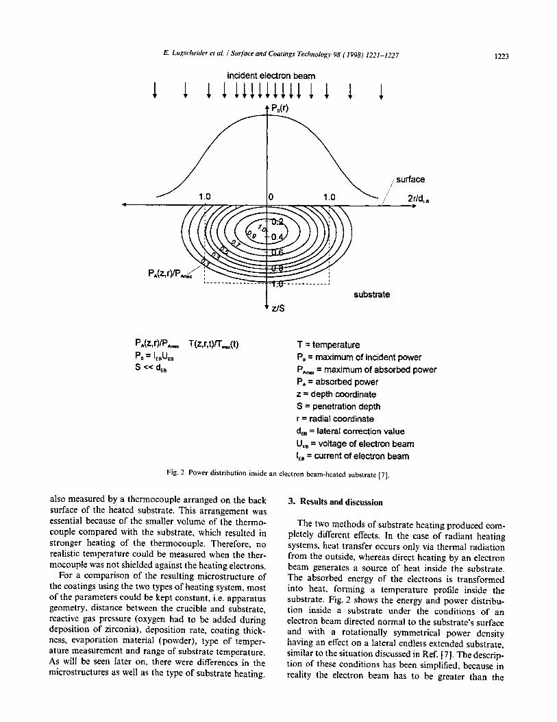
Fig. 3. Temperature profile inside a radiant-heated substrate.
extension of the substrate for a homogeneous lateralheat distribution. Therefore, the electron beam is notnormal to the surface of the substrate at all points, andis not effective at the sides of the substrate.
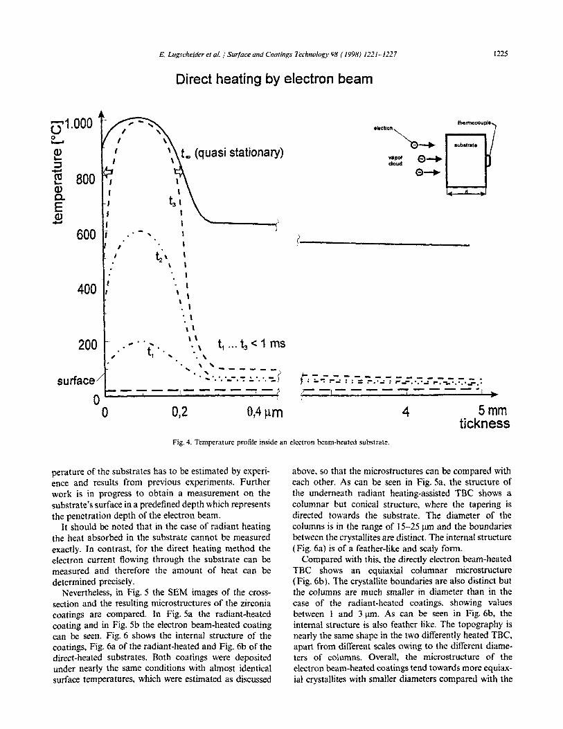
The two heating methods led to different temperaturedistributions inside the substrate. Fig. 3 shows the sche•matic temperature profile at different times in a substrateof 5 mm thickness, using radiation heating. It can beobserved that some time is needed before a continuousheat distribution develops inside the substrate. Thefinally adjusted temperature gradient depends only onthe heated material and its physical properties. In Fig. 4the temperature distribution for direct heating byelectrons is suggested at different times in a substrate ofthe same dimensions, based on theory taken from theliterature [7] and observations, as well as measurementstaken during our own experiments. In a very small areanear the heated surface the absorbed energy of theelectrons is transformed into heat. The depth of this areadepends directly on the electron beam voltage and is
given in the literature asO.27l!m for 10 kV [8]. Therefore,at first this area will be heated in milliseconds up to therequired surface temperature, followed by a heat flow inthe substrate from the hottest section to the areas oflower temperature, which is indicated by the arrows inFig. 4. Thus, in the case of direct heating by an electronbeam, the surface temperature will be reached immedi•ately, while on the back of the substrate the measuredtemperature values are much lower. These suggestionswere confirmed by experiments, e.g. EB-PVD coating ofa high speed steel (HSS) with a tempering temperatureof about 560°C. While a temperature of 420 °e wasmeasured on the back of the sample during the depositionprocess, the cross-section shows a small area near thesurface of the substrate where the material has beentempered. Therefore, the temperature on the heated Sur•face must have been higher than 560°C. Such observa•tions indicate the suggested temperature profiles. Sinceno concrete measurements have been made up to nowfor this direct heating method, the required surface tern-
E. Lugscheider et al. ! Surface and Coatings Technology 98 (J998) /22/-/227 1225
Direct heating by electron beam
5mmtickness
4
aleetron""
"a--.. aubR..t.
t-. 7 _- _-.7'.- - - - - - - _ - ""1 • - . . - • • =:-.'': : r- _- ....... .: ~ .. -_ .•••• .". ...
f------------_
O,41lm
t, ... t3 < 1 ms
t... (quasi stationary)
0,2
,,t3 ,,,,,
t;\ ,\ ,,,
\ ,\. ,
'. ,\ ,\ \'. \.,
\ ,' .... ------)........._-.-.r: ':".'.-:,,)
...t, .....
----1----.....,.-
200
surface
oo
0 1.0000...-
~='....co 800s.-a>a.Ea>....
600 ,,
I
400
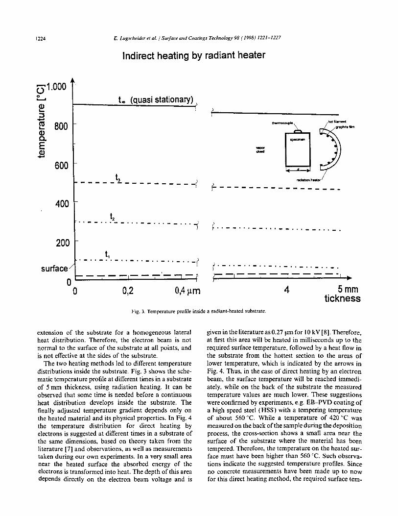
Fig. 4. Temperature profile inside an electron beam-heated substrate.
perature of the substrates has to be estimated by experi•ence and results from previous experiments. Furtherwork is in progress to obtain a measurement on thesubstrate's surface in a predefined depth which representsthe penetration depth of the electron beam.
It should be noted that in the case of radiant heatingthe heat absorbed in the substrate cannot be measuredexactly. In contrast. for the direct heating method theelectron current flowing through the substrate can bemeasured and therefore the amount of heat can bedetermined precisely.
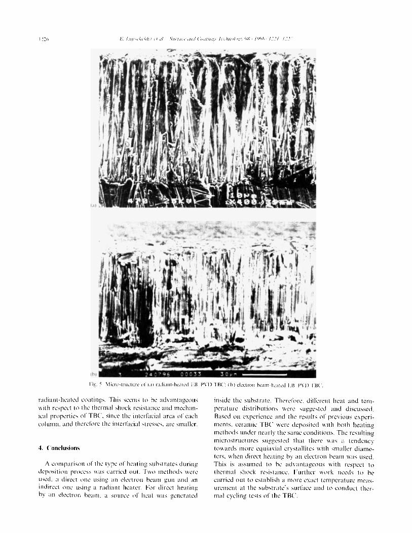
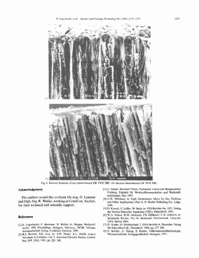
Nevertheless, in Fig. 5 the SEM images of the cross•section and the resulting microstructures of the zirconiacoatings are compared. In Fig. 5a the radiant-heatedcoating and in Fig. 5b the electron beam-heated coatingcan be seen. Fig. 6 shows the internal structure of thecoatings, Fig. 6a of the radiant-heated and Fig. 6b of thedirect-heated substrates. Both coatings were depositedunder nearly the same conditions with almost identicalsurface temperatures. which were estimated as discussed
above. so that the microstructures can be compared witheach other. As can be seen in Fig. Sa. the structure ofthe underneath radiant heating-assisted TBC shows acolumnar but conical structure. where the tapering isdirected towards the substrate. The diameter of thecolumns is in the range of 15-25 J.tm and the boundariesbetween the crystallites are distinct. The internal structure(Fig. 6a) is of a feather-like and scaly fonn.
Compared with this, the directly electron beam-heatedTBC shows an equiaxial columnar microstructure(Fig. 6b). The crystallite boundaries are also distinct butthe columns are much smaller in diameter than in thecase of the radiant-heated coatings. showing valuesbetween I and 3 !lm. As can be seen in Fig. 6b. theinternal structure is also feather like. The topography isnearly the same shape in the two differently heated TBe.apart from different scales owing to the different diame•ters of columns. Overall, the microstructure of theelectron beam-heated coatings tend towards more equiax•ial crystallites with smaller diameters compared with the
(hi
"Ig, '. \lienhtruelure or (;1) radiant-heated FB I'Vi) TBC: (h) electron heam-healL'd L1l "Vi) TBe.
radiant-heated coatings, This seems to he advantageouswith respect to the thermal shock resistance and mechan•ical properties of TBe since the interfacial area of eachcolumn. and therefore the interracial stresses. arc smaller.
4. Conclusions
;\ comparison of the type of heating suhstrates duringdeposition process was carried oul. Two methods wereused. a direct one using an electron heam gun and anindirect one using a radiant heater. For direct hcatinghy an electron heam. a source of heat was generated
inside the suhstrate, Thercrore. different heat and tem•perature distrihutions were suggested and discussed,Based on expericnce and the results or prcvious experi•ments. ceramic TBe were deposited with hoth heatingmethods under nearly the same conditions. The resultingmicrostructures suggested that there was a tendencytowards more eljuiaxial crystallites with smaller diame•ters. when direct heating hy an electron heam was used,This is assumed to he advantageous with respect tothermal shock resistance. Further work needs to hecarried out to estahlish a more exact temperature meas•urement at the substrate's surrace and to conduct ther•mal cycling tests of the TBe.
E. LlIgscheider elli/. SlIr!lICe lIlld COlilings Techn%gr Wi (I9Wi) /::::/ /::::7
• -,......', ..... ~'
(a)
,
1227
(h)
Fig. 6. Internal structurc of (a) radiant-heated EB PVD TBC: (b) electron beam-heated EB PVD TBe.
Acknowledgement
The authors would like to thank Dr.-Ing. O. Lemmerand Dipl.-Ing. R. Wenke, working at CemeCon, Aachen,for their technical and scientific support.
References
[I] E. Lugscheider. C. Barimani. M. Moller. G. Dapper. Werkstolj~
woche 1996 Proceedings. Stuttgart. Germany. DGM Informa•tionsgcsellschaft Verlag. Frankfurt. Gcmany. 1997.
[2] RJ. Brallon. S.K. Lau. in: A.H. Hcuer. A.L. Hobbs (Eds.).Advances in Ceramics. vol. J. American Ceramic Society. Colum•bus. OH. USA. 1981. pp. 226 240.
[J] U. Schulz. Doctoral Thesis. Technische Universitat BergakademieFreiberg. Fakultat fUr Werkstolfwissenschaften und Werkstolf•technologic. May 1995.
[4] G.W. Meetham. in: High Temperature Alloys for Gas Turbinesand Othcr Applications. Part II. D. Reidel Publishing Co.. Liege,1986.
[5] O. Knotek. F. Loffier. W. Beele. in: VOl-Berichte No. 1021. Verlagdes Vereins Deutscher Ingenieure (VOl). Dusseldorf, 1993.
[6] W.A. Nelson. R.M. Orenstein. P.S. DiMascio. e.A. Johnson. in:Sermatech Review. No. 54. Sermatech International. Limerick.USA. Spring 1996.
[7] D. Kuper. in: Strahltechnik 2. DVS-Berichte 4. Deutscher VerlagfUr Schweil3technik. Dusseldorf. 1986. pp. 217- 244.
[8] S. Schiller. U. Heisig. S. Panzer. Elektronenstrahltechnologie.Wissenschaftliche Verlagsgcsellschaft. Stullgart, 1977.
Recommended


![UvA-DARE (Digital Academic Repository) Hybrid resonators ... · cavity using ion-beam-assisted chemical vapour deposition [85], deposited in a multi-step lithography process [94,](https://img.pdfslide.net/doc/110x75/601bad523ed18543c063a5c3/uva-dare-digital-academic-repository-hybrid-resonators-cavity-using-ion-beam-assisted.jpg)