tW ea rt
rou d h clockn e
CG PUMPSPRODUCT CATALOGUE
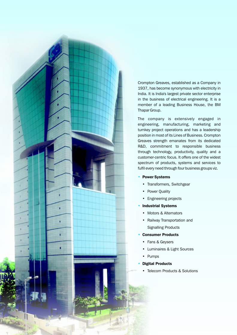
Crompton Greaves, established as a Company in
1937, has become synonymous with electricity in
India. It is India's largest private sector enterprise
in the business of electrical engineering. It is a
member of a leading Business House, the BM
Thapar Group.
The company is extensively engaged in
engineering, manufacturing, marketing and
turnkey project operations and has a leadership
position in most of its Lines of Business. Crompton
Greaves strength emanates from its dedicated
R&D, commitment to responsible business
through technology, productivity, quality and a
customer-centric focus. It offers one of the widest
spectrum of products, systems and services to
fulfil every need through four business groups viz.
Power Systems
• Transformers, Switchgear
• Power Quality
• Engineering projects
Industrial Systems
• Motors & Alternators
• Railway Transportation and
Signalling Products
Consumer Products
• Fans & Geysers
• Luminaires & Light Sources
• Pumps
Digital Products
• Telecom Products & Solutions
•
•
•
•
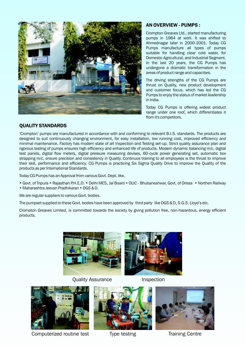
AN OVERVIEW - PUMPS :
. Today CG Pumps manufacture all types of pumps suitable for handling clear cold water, for Domestic Agricultural, and Industrial Segment. In the last 20 years, the CG Pumps has undergone a dramatic transformation in the areas of product range and capacities.
The driving strengths of the CG Pumps are thrust on Quality, new product development and customer focus, which has led the CG Pumps to enjoy the status of market leadership in India.
Today CG Pumps is offering widest product range under one roof, which differentiates it from it's competitors.
QUALITY STANDARDS
‘Crompton’ pumps are manufactured in accordance with and conforming to relevant B.I.S. standards. The products are designed to suit continuously changing environment, for easy installation, low running cost, improved efficiency and minimal maintenance. Factory has modern state of art Inspection and Testing set-up. Strict quality assurance plan and rigorous testing of pumps ensures high efficiency and enhanced life of products. Modern dynamic balancing m/c, digital test panels, digital flow meters, digital pressure measuring devises, 60-cycle power generating set, automatic box strapping m/c, ensure precision and consistency in Quality. Continuos training to all employees is the thrust to improve their skill, performance and efficiency. CG Pumps is practicing Six Sigma Quality Drive to improve the Quality of the products as per International Standards.
Today CG Pumps has an Approval from various Govt. Dept. like,
• Govt. of Tripura • Rajasthan P.H.E.D. • Delhi MES, Jal Board • OLIC - Bhubaneshwar, Govt. of Orissa • Northen Railway • Maharashtra Jeevan Pradhikaran • DGS & D.
We are regular suppliers to various Govt. bodies.
The pumpset supplied to these Govt. bodies have been approved by third party like DGS & D, S.G.S. Lloyd’s etc.
Crompton Greaves Limited, is committed towards the society by giving pollution free, non-hazardous, energy efficient products.
Crompton Greaves Ltd., started manufacturing pumps in 1964 at worli. It was shifted to Ahmednagar later in 2000-2001
Quality Assurance Inspection
Computerized routine test Type testing Training Centre

• Efficient Customer Service
• Virtually Maintenance Free
• Superior Technology
• Low Power Consumption
• Wide Dealer Network
• Submersible • Open well • Monoblock • Diesel Engine Pumps •
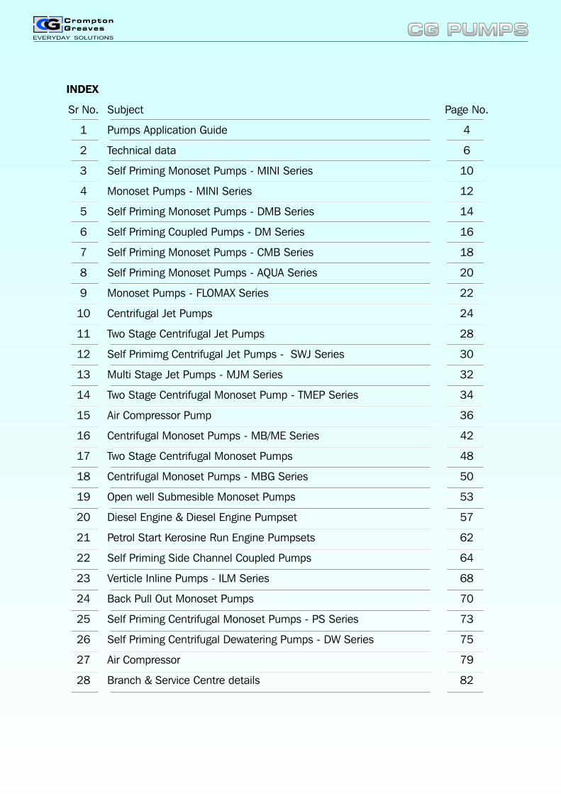
INDEX
Sr No. Subject Page No.
1 Pumps Application Guide 4
2 Technical data 6
3 Self Priming Monoset Pumps - MINI Series 10
4 Monoset Pumps - MINI Series 12
5 Self Priming Monoset Pumps - DMB Series 14
6 Self Priming Coupled Pumps - DM Series 16
7 Self Priming Monoset Pumps - CMB Series 18
8 Self Priming Monoset Pumps - AQUA Series 20
9 Monoset Pumps - FLOMAX Series 22
10 Centrifugal Jet Pumps 24
11 Two Stage Centrifugal Jet Pumps 28
12 Self Primimg Centrifugal Jet Pumps - SWJ Series 30
13 Multi Stage Jet Pumps - MJM Series 32
14 Two Stage Centrifugal Monoset Pump - TMEP Series 34
15 Air Compressor Pump 36
16 Centrifugal Monoset Pumps - MB/ME Series 42
17 Two Stage Centrifugal Monoset Pumps 48
18 Centrifugal Monoset Pumps - MBG Series 50
19 Open well Submesible Monoset Pumps 53
20 Diesel Engine & Diesel Engine Pumpset 57
21 Petrol Start Kerosine Run Engine Pumpsets 62
22 Self Priming Side Channel Coupled Pumps 64
23 Verticle Inline Pumps - ILM Series 68
24 Back Pull Out Monoset Pumps 70
25 Self Priming Centrifugal Monoset Pumps - PS Series 73
26 Self Priming Centrifugal Dewatering Pumps - DW Series 75
27 Air Compressor 79
28 Branch & Service Centre details 82
CG PUMPSCG PUMPS
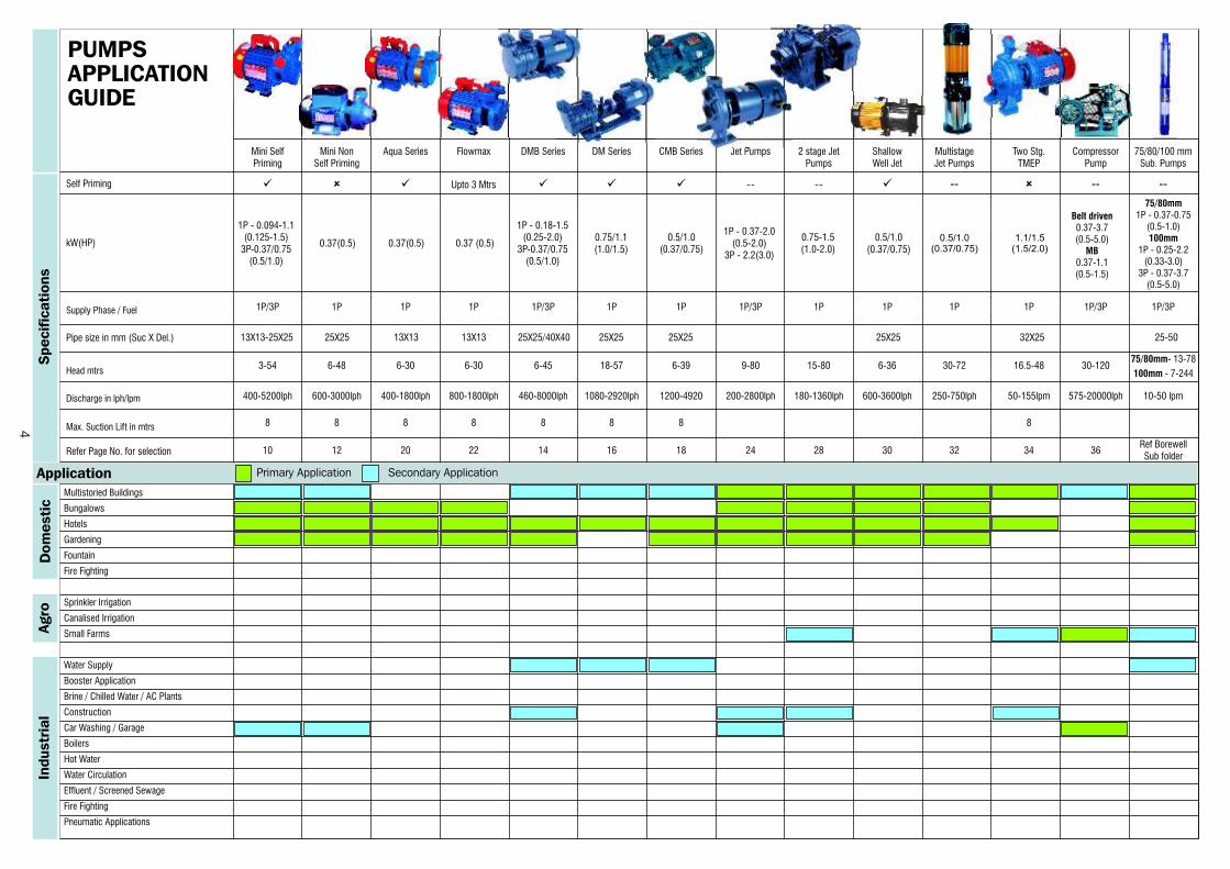
Multistoried Buildings
Bungalows
Hotels
Gardening
Fountain
Fire Fighting
Sprinkler Irrigation
Canalised Irrigation
Small Farms
Water Supply
Booster Application
Brine / Chilled Water / AC Plants
Construction
Car Washing / Garage
Boilers
Hot Water
Water Circulation
Effluent / Screened Sewage
Fire Fighting
Pneumatic Applications
0.75/1.1(1.0/1.5)
1P - 0.37-2.0 (0.5-2.0)
3P - 2.2(3.0)
0.5/1.0 (0.37/0.75)
1.1/1.5(1.5/2.0)
Belt driven0.37-(0.5-5.0)
MB0.37-1.1(0.5-1.5)
3.7
Mini Self Mini Non Aqua Series Flowmax DMB Series DM Series CMB Series Jet Pumps 2 stage Jet Shallow Multistage Two Stg. Compressor 75/80/100 mm Priming Self Priming Pumps Well Jet Jet Pumps TMEP Pump Sub. Pumps
ü û üUpto 3 Mtrs ü ü ü -- -- ü -- û -- --
1P/3P 1P 1P 1P 1P/3P 1P 1P 1P/3P 1P 1P 1P 1P 1P/3P 1P/3P
400-5200lph 600-3000lph 400-1800lph 800-1800lph 460-8000lph 1080-2920lph 1200-4920 200-2800lph 180-1360lph 600-3600lph 250-750lph 50-155lpm 575-20000lph 10-50 lpm
8 8 8 8 8 8 8 8
10 12 20 22 14 16 18 24 28 30 32 34 36
3-54 6-48 6-30 6-30 6-45 18-57 6-39 9-80 15-80 6-36 30-72 16.5-48 30-120
Self Priming
1P - 0.094-1.1 (0.125-1.5)
3P-0.37/0.75 (0.5/1.0)
0.37(0.5) 0.37(0.5) 0.37 (0.5)
1P - 0.18-1.5 (0.25-2.0)
3P-0.37/0.75(0.5/1.0)
0.5/1.0 (0.37/0.75)
0.75-1.5(1.0-2.0)
0.5/1.0 (0.37/0.75)
75/80mm1P - 0.37-0.75
(0.5-1.0)100mm
1P - 0.25-2.2(0.33-3.0)
3P - 0.37-3.7(0.5-5.0)
75/80mm- 13-78
100mm - 7-244
kW(HP)
Supply Phase / Fuel
Head mtrs
Discharge in lph/lpm
Max. Suction Lift in mtrs
Refer Page No. for selectionRef BorewellSub folder
Pipe size in mm (Suc X Del.) 13X13-25X25 25X25 13X13 13X13 25X25/40X40 25X25 25X25 25X25 32X25 25-50
Specif
icati
ons
Dom
esti
cAgro
Industr
ial
Application
PUMPSAPPLICATIONGUIDE
Primary Application Secondary Application
4
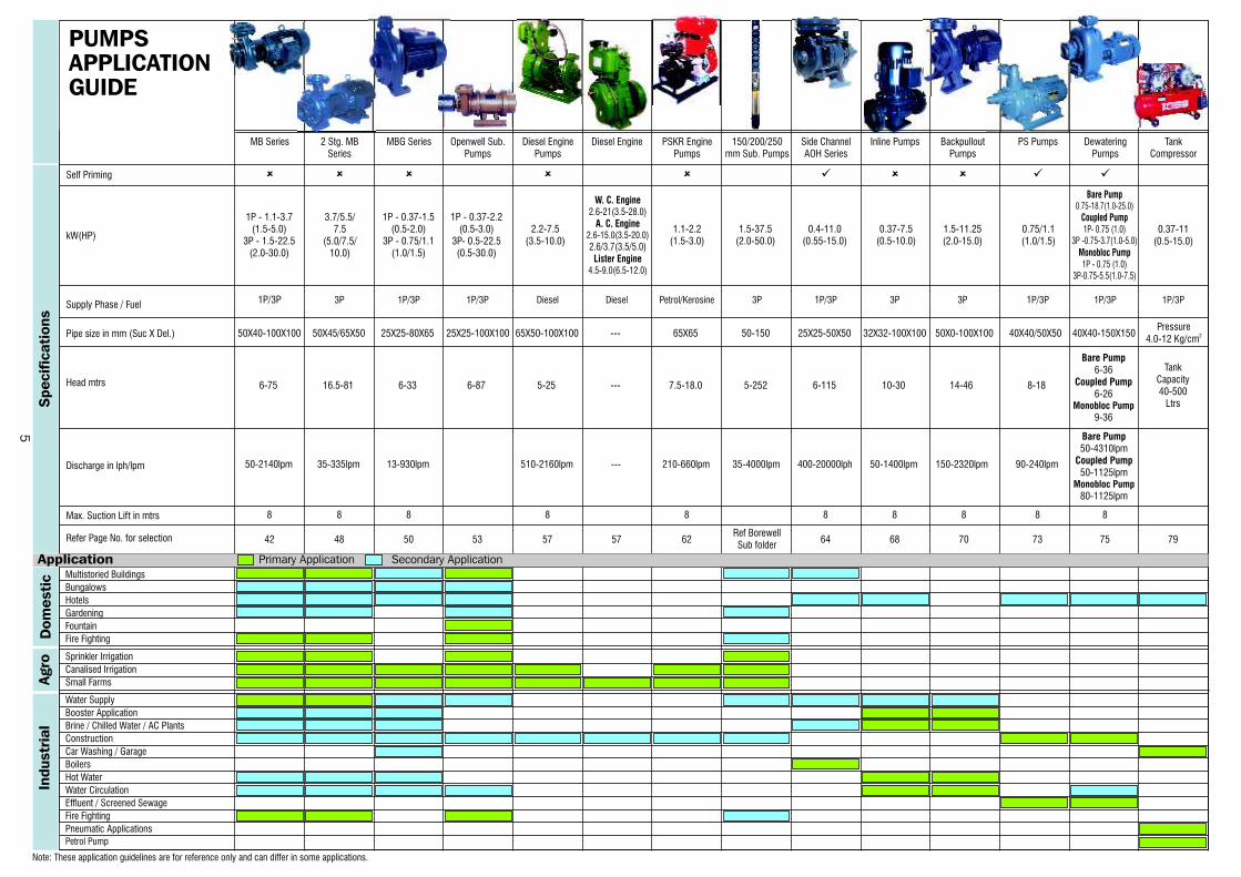
APPLICATION
Multistoried Buildings
Bungalows
Hotels
Gardening
Fountain
Fire Fighting
Sprinkler Irrigation
Canalised Irrigation
Small Farms
Water Supply
Booster Application
Brine / Chilled Water / AC Plants
Construction
Car Washing / Garage
Boilers
Hot Water
Water Circulation
Effluent / Screened Sewage
Fire Fighting
Pneumatic Applications
Petrol Pump
W. C. Engine2.6-21(3.5-28.0)
A. C. Engine2.6-15.0(3.5-20.0)
2.6/3.7(3.5/5.0)Lister Engine
4.5-9.0(6.5-12.0)
1.5-37.5(2.0-50.0)
1.5-11.25(2.0-15.0)
0.75/1.1 (1.0/1.5)
Bare Pump0.75-18.7(1.0-25.0)
Coupled Pump1P- 0.75 (1.0)
3P -0.75-3.7(1.0-5.0)Monobloc Pump1P - 0.75 (1.0)
3P-0.75-5.5(1.0-7.5)
8 8 8 8 8 8 8 8 8 8
42 48 50 53 57 57 62 64 68 70 73 75 79
1P/3P 1 13P 1P/3P 1P/3P Diesel Diesel Petrol/Kerosine 3P P/3P 3P 3P P/3P 1P/3P 1P/3P
Self Priming
1P - 1.1-3.7 (1.5-5.0)
3P - 1.5-22.5(2.0-30.0)
3.7/5.5/7.5
(5.0/7.5/10.0)
1P - 0.37-1.5(0.5-2.0)
3P - 0.75/1.1(1.0/1.5)
1P - 0.37-2.2(0.5-3.0)
3P- 0.5-22.5(0.5-30.0)
2.2-7.5(3.5-10.0)
1.1-2.2(1.5-3.0)
0.4-11.0 (0.55-15.0)
0.37-7.5(0.5-10.0)
0.37-11(0.5-15.0)
kW(HP)
Supply Phase / Fuel
Head mtrs
Discharge in lph/lpm
Max. Suction Lift in mtrs
Refer Page No. for selectionRef BorewellSub folder
MB Series 2 Stg. MB MBG Series Openwell Sub. Diesel Engine Diesel Engine PSKR Engine 150/200/250 Side Channel Inline Pumps Backpullout PS Pumps Dewatering TankSeries Pumps Pumps Pumps mm Sub. Pumps AOH Series Pumps Pumps Compressor
û û û û û ü û û ü ü
Pipe size in mm (Suc X Del.)Pressure
50X40-100X100 50X45/65X50 25X25-80X65 25X25-100X100 65X50-100X100 --- 65X65 50-150 25X25-50X50 32X32-100X100 50X0-100X100 40X40/50X50 40X40-150X150 24.0-12 Kg/cm
6-75 16.5-81 6-33 6-87 5-25 --- 7.5-18.0 5-252 6-115 10-30 14-46 8-18
Bare Pump6-36
Coupled Pump6-26
Monobloc Pump 9-36
TankCapacity40-500
Ltrs
50-2140lpm 35-335lpm 13-930lpm 510-2160lpm --- 210-660lpm 35-4000lpm 400-20000lph 50-1400lpm 150-2320lpm 90-240lpm
Bare Pump50-4310lpm
Coupled Pump50-1125lpm
Monobloc Pump80-1125lpm
Note: These application guidelines are for reference only and can differ in some applications.
Specif
icati
ons
Dom
esti
cAgro
Industr
ial
Application
PUMPSAPPLICATIONGUIDE
Primary Application Secondary Application
5
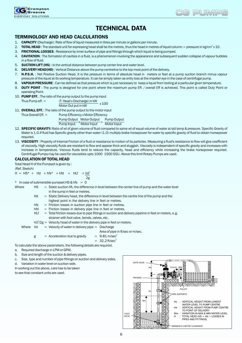
12.5mm. MIN.
PIPE SUPPORTS
PULLEY
MINIMUM 0.5 METRE CLEARANCE
FOOTVALVE
Hd
Hs
Wm
GATE VALVE
PACKING
Hs : VERTICAL HEIGHT FROM LOWEST WATER LEVEL TO PUMP CENTRE.
Hd : VERTICAL HEIGHT FROM PUMP CENTRE TO POINT OF DELIVERY.
Wm : VARIATION IN MAX & MIN WATER LEVELH : TOTAL HEAD (HS + Hd + LOSSES IN
PIPES AND FITTINGS)
TECHNICAL DATA
1. CAPACITY (Discharge): Rate of flow of liquid measured in litres per minute or gallons per minute.
2. TOTAL HEAD : The standard unit for expressing head shall be the metres, thus the head in metres of liquid column = pressure in kg/cm x 10.
3. FRICTIONAL LOSSES : Resistance by inner surface of pipe and fittings through which liquid is being pumped.
4. CAVITATION : The formation of cavities in a fluid, is a phenomenon involving the appearance and subsequent sudden collapse of vapour bubbles in a flow of fluid.
5. SUCTION LIFT (HS) : Is the vertical distance between pump center line and water level.
6. DELIVERY HEAD(HD) : Vertical Distance above the pump centreline to the top most point of the delivery.
7. N.P.S.H. : Net Positive Suction Head. It is the pressure in terms of absolute head in meters or feet at a pump suction branch minus vapour pressure of the liquid at its working temperature. It can be simply taken as entry loss at the impeller eye in the case of centrifugal pump.
8. VAPOUR PRESSURE : Can be defined as that pressure which is just necessary to keep a liquid from boiling at a particular given temperature.
9. DUTY POINT : The pump is designed for one point where the maximum pump Eff. / overall Eff is achieved. This point is called Duty Point or operating Point.
10. PUMP EFF. : The ratio of the pump output to the pump input
Thus Pump eff. = (T. Head x Discharge) in kW x 100
Motor Out put in kW
11. OVERALL EFF. : The ratio of the pump output to the motor input
Thus Overall Eff. = Pump Efficiency x Motor Efficiency
Pump Output Motor Output Pump Outputx =
Pump Input Motor Input Motor Input
12. SPECIFIC GRAVITY: Ratio of wt of given volume of fluid compared to same wt of equal volume of water at std temp & pressure. Specific Gravity of Water is 1.0.If fluid has Specific gravity other than water (1.0) multiply brake horsepower for water by specific gravity of fluid to obtain horsepower required.
13. VISCOSITY : Property of Internal Friction of a fluid or resistance to motion of its particles. Measuring a fluid's resistance to flow will give coefficient of viscosity. High viscosity fluids are resistant to flow and appear thick and sluggish. Viscosity is independent of specific gravity and increases with increase in temperature. Viscous fluids tend to reduce the capacity, head and efficiency while increasing the brake horsepower required. Centrifugal Pumps may be used for viscosities upto 1000 1500 SSU. Above this limit Rotary Pumps are used.
CALCULATION OF TOTAL HEADTotal Head H of the Pumpset is given by :
(Ref. Sketch)2H = HS* + Hd + hfs* + hfd + HLf + Vd
2g
* In case of submersible pumpset HS & hfs = 0
Where HS = Static suction lift, the difference in level between the center line of pump and the water level
in the sump in feet or metres.
Hd = Static Delivery head, the difference in level between the centre line of the pump and the
highest point in the delivery line in feet or metres.hfs = Friction losses in suction pipe line in feet or metres.hfd = Friction losses in delivery pipe line in feet or metres.HLf = Total friction losses due to pipe fittings in suction and delivery pipeline in feet or meters, e.g.
strainer with foot valve, bends, valves, etc.2Vd /2g = Velocity head of water in the delivery pipe in feet or meters.
Where Vd = Velocity of water in delivery pipe = Discharge
Area of pipe in ft/sec or m/sec. 2g = Acceleration due to gravity = 9.81 m/sec
2= 32.2 ft/sec
To calculate the above parameters, the following details are required.
a. Required discharge in LPM or GPM.
b. Size and length of the suction & delivery pipes.
c. Size, type and number of pipe fittings on suction and delivery sides.
d. Variation in water level on suction side.
In working out the above, care has to be taken
to see that constant units are used.
2
TERMINOLOGY AND HEAD CALCULATIONS
CG PUMPSCG PUMPS
6
TABLE II
Length of straight pipe in meters giving equivalent resistance of flow in valves and fittings.
Size ofpipe in Elbow Medium long Elbow Bend Valve Valve Valve Valve
mm (Std) Elbow Elbow or Check Valve (NRV)
13 0.46 0.43 0.34 0.24 1.04 1.16 0.107 4.90 2.56 1.01
20 0.61 0.55 0.43 0.31 1.37 1.53 0.143 6.70 3.66 1.53
25 0.82 0.70 0.52 0.40 1.77 1.86 0.18 8.24 4.57 2.04
40 1.31 1.10 0.85 0.61 2.74 3.05 0.29 13.40 6.71 3.05
50 1.67 1.40 1.07 0.76 3.35 3.96 0.37 17.40 8.54 3.96
63 1.98 1.65 1.28 0.92 4.26 4.57 0.42 20.10 10.00 5.18
76 2.47 2.00 1.55 1.15 5.18 5.49 0.52 25.90 12.00 6.10
100 3.35 2.77 2.13 1.53 6.71 7.31 0.70 33.50 17.70 8.23
125 4.26 3.66 2.78 1.86 8.24 9.45 0.88 42.60 21.30 10.00
150 4.87 4.26 3.35 2.35 10.80 11.50 1.07 47.70 25.30 12.20
200 6.40 5.48 4.26 3.05 13.10 14.90 1.37 67.10 33.50 16.20
250 7.62 6.71 5.18 3.96 17.10 19.00 1.74 88.50 42.60 20.40
300 9.75 7.92 6.10 4.57 20.10 23.00 2.04 100.50 51.80 24.40
0 0 0 090 90 90 45 TEE Return Gate Globe Angle Foot
Friction in long pipeline is to be calculated.
TABLE 2: Frictional head lost in GI pipe
Q Head lost in m per 100m
Lpm(nominal 40 50 65 80 100
dia mm)
40 1.15 0.38 0.10 0.03 0.01
60 2.57 0.84 0.22 0.08 0.03
80 4.58 1.50 0.40 0.14 0.05
100 7.16 2.36 0.63 0.22 0.07
120 10.30 3.38 0.91 0.32 0.11
150 16.10 5.30 1.42 0.50 0.17
180 23.20 7.60 2.05 0.72 0.24
240 41.25 13.52 3.64 1.29 0.42
300 64.45 21.12 5.69 2.01 0.66
360 - 30.41 8.19 2.90 0.95
400 - 37.55 10.11 3.58 1.17
500 - - 15.80 5.59 1.83
Note: For intermediate value Q find head lost in friction hfq by following formula
Hfq = (Q/Q1) x (Q/Q1) xhfq1
Where hfq1 is head lost in Q1 discharge.
d) Water requirement:
The water requirement of the crop depends upon the
(i) Nature of the crop
(ii) Atmospheric conditions
(iii) Nature of soil
CG PUMPSCG PUMPS
7

CONVERSION TABLE
Discharge :
1 Imp Gallon - 4.546 ltrs.
1 US Gallon - 3.785 ltrs.
1 Cu m. - 1000 ltrs.
1 Cu ft. - 28.32 ltrs.
Discharge rate :31 m /h - 16.67 I/min.31 m /s - 60,000 I/min.
1 I/s - 60 I/min
1 Cu ft/s - 1699.2 I/min.
1 Imp. GPH - 0.0757 I/min
0.00126 I/Sec.
Head :
1 mtrs. - 3.28 ft.
1 ft - 0.3048 m.21 kg/cm - 10 mtrs
Pressure :21 Atmosphere - 1.033 kg/cm
21 Atmosphere - 14.7 Ib/in
1 Atmosphere - 10.34 mwc21 Ib/in - 0.704 mwc21 Ib/in - 2.31 ft wc21 Ib/in - 51.6 mm of mercury.
1 cusec - 1705 lpm
- 1 Acre inch/hr
1 Cu mec - 20558.3 lpm.
- 1 Acre ft/hr.
Power :
1 HP (Si) - 0.746 kW
- 746 W
1 HP (Metric) - 0.736 kW
- 736W
1 kW - 1000 W
Weight :
1 kg. - 1000 gm.
1 kg. - 2.2046 lb.
1 lb. - 0.4536 kg.
DISCHARGE RATE TABLE
Veenotch Veenotch Discharge Dischargereading reading rate in rate inin inch in mm. GPH (imp) lpm.
1/2" 12.7 21 1.59
3/4" 19.05 57.42 4.35
1" 25.4 117.22 8.88
1¼" 31.75 203.8 15.44
1½" 38.1 320.5 24.28
1¾" 44.45 469.52 35.57
2" 50.8 653.8 49.53
2¼" 57.15 875.56 66.33
2½" 63.5 1137.05 86.14
2¾" 69.85 1440.12 109.1
3" 76.2 1786.49 135.39
3¼" 82.55 2179.45 165.11
3¾" 95.25 3108.07 235.46
4" 101.6 3647.56 276.33
4¼" 107.95 4239.31 321.16
4½" 114.3 4884.92 370.07
4¾" 120.65 5585.84 423.17
5" 127 6343.95 480.6
5¼" 133.35 7159.55 542.39
5½" 139.7 8034.97 608.71
5¾" 146.05 8991.64 679.67
6" 152.4 9970.22 755.32
6¼" 158.75 11032.43 835.79
6½" 165.1 12159.44 921.17
6¾" 171.45 13352.46 1011.55
7" 177.08 14466.41 1095.94
7¼" 184.15 15941.38 1207.68
7½" 190.5 17339.65 1313.61
7¾" 196.85 18808.55 1424.89
8" 203.2 20349.38 1541.62
CG PUMPSCG PUMPS
8
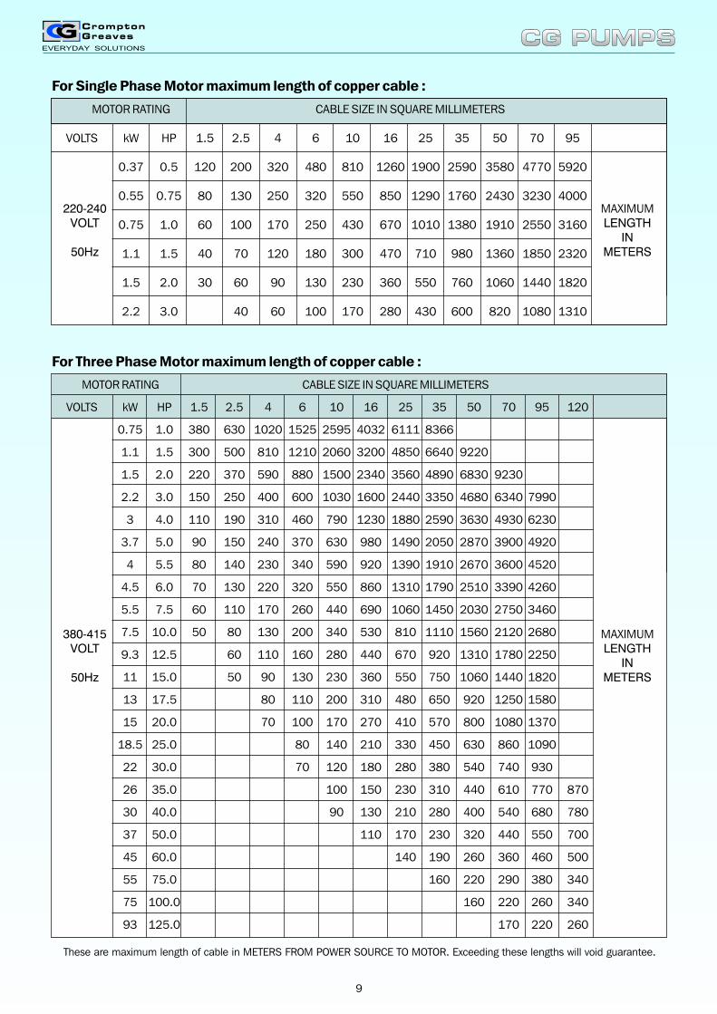
For Single Phase Motor maximum length of copper cable :
MOTOR RATING CABLE SIZE IN SQUARE MILLIMETERS
VOLTS kW HP 1.5 2.5 4 6 10 16 25 35 50 70 95
0.37 0.5 120 200 320 480 810 1260 1900 2590 3580 4770 5920
0.55 0.75 80 130 250 320 550 850 1290 1760 2430 3230 4000
0.75 1.0 60 100 170 250 430 670 1010 1380 1910 2550 3160
1.1 1.5 40 70 120 180 300 470 710 980 1360 1850 2320
1.5 2.0 30 60 90 130 230 360 550 760 1060 1440 1820
2.2 3.0 40 60 100 170 280 430 600 820 1080 1310
For Three Phase Motor maximum length of copper cable :
MOTOR RATING CABLE SIZE IN SQUARE MILLIMETERS
VOLTS kW HP 1.5 2.5 4 6 10 16 25 35 50 70 95 120
0.75 1.0 380 630 1020 1525 2595 4032 6111 8366
1.1 1.5 300 500 810 1210 2060 3200 4850 6640 9220
1.5 2.0 220 370 590 880 1500 2340 3560 4890 6830 9230
2.2 3.0 150 250 400 600 1030 1600 2440 3350 4680 6340 7990
3 4.0 110 190 310 460 790 1230 1880 2590 3630 4930 6230
3.7 5.0 90 150 240 370 630 980 1490 2050 2870 3900 4920
4 5.5 80 140 230 340 590 920 1390 1910 2670 3600 4520
4.5 6.0 70 130 220 320 550 860 1310 1790 2510 3390 4260
5.5 7.5 60 110 170 260 440 690 1060 1450 2030 2750 3460
7.5 10.0 50 80 130 200 340 530 810 1110 1560 2120 2680
9.3 12.5 60 110 160 280 440 670 920 1310 1780 2250
11 15.0 50 90 130 230 360 550 750 1060 1440 1820
13 17.5 80 110 200 310 480 650 920 1250 1580
15 20.0 70 100 170 270 410 570 800 1080 1370
18.5 25.0 80 140 210 330 450 630 860 1090
22 30.0 70 120 180 280 380 540 740 930
26 35.0 100 150 230 310 440 610 770 870
30 40.0 90 130 210 280 400 540 680 780
37 50.0 110 170 230 320 440 550 700
45 60.0 140 190 260 360 460 500
55 75.0 160 220 290 380 340
75 100.0 160 220 260 340
93 125.0 170 220 260
MAXIMUMLENGTH
INMETERS
MAXIMUMLENGTH
INMETERS
220-240VOLT
50Hz
380-415VOLT
50Hz
These are maximum length of cable in METERS FROM POWER SOURCE TO MOTOR. Exceeding these lengths will void guarantee.
CG PUMPSCG PUMPS
9
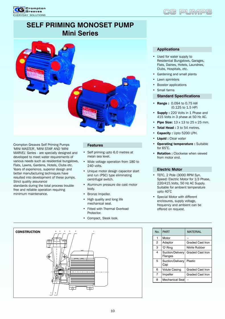
Crompton Greaves Self Priming Pumps 'MINI MASTER', 'MINI STAR' AND 'MINI MARVEL' Series - are specially designed and developed to meet water requirements of various needs such as residential bungalows, Flats, Lawns, Gardens, Hotels, Clubs etc. Years of experience, superior design and better manufacturing techniques have resulted into development of these pumps. Strict quality assurance standards during the total process trouble free and reliable operation requiring minimum maintenance.
• Self priming upto 6.0 metres at mean sea level.
• Wide voltage operation from 180 to 240 volts.
• Unique motor design capacitor start and run (PSC) type eliminating centrifugal switch.
• Aluminum pressure die cast motor body.
• Bronze Impeller.
• High quality and long life mechanical seal.
• Fitted with Thermal Overload Protector.
• Compact, Sleek look.
Features
• Used for water supply toResidential Bungalows, Garages, Flats, Dairies, Hotels, Laundries, Clubs, Hospitals, etc.
• Gardening and small plants
• Lawn sprinklers
• Booster applications
• Small farms
Applications
Standard Specifications
• Range : 0.094 to 0.75 kW(0.125 to 1.5 HP)
• Supply : 220 Volts in 1 Phase and 415 Volts in 3 phase at 50 Hz AC.
• Pipe Size: 13 x 13 to 25 x 25 mm.
• Total Head : 3 to 54 metres.
• Capacity : Upto 5200 LPH.
• Liquid : Clear water
• Operating temperature : Suitable 0for 65 C.
• Rotation : Clockwise when viewed from motor end.
Electric Motor
• TEFC, 2 Pole (3000 RPM Syn. Speed) Electric Motor for 1/3 Phase, 220/415 Volts, 50 Hz AC Supply. Suitable for ambient temperature
0upto 40 C
• Special Motor with different enclosures, supply voltage, frequency and ambient can be offered on request.
SELF PRIMING MONOSET PUMPMini Series
1245
87
6 3CONSTRUCTION No.
2
1
Adaptor
Motor
PART MATERIAL
_
4
3
Suction/DeliveryCap
Impeller
Volute Casing
'O' Ring
Suction/DeliveryFlanges
Nitrile Rubber
Graded Cast Iron
Graded Cast Iron
Graded Cast Iron
Graded Cast Iron
Plastic5
6
7
Mechanical Seal8 _
CG PUMPSCG PUMPS
10
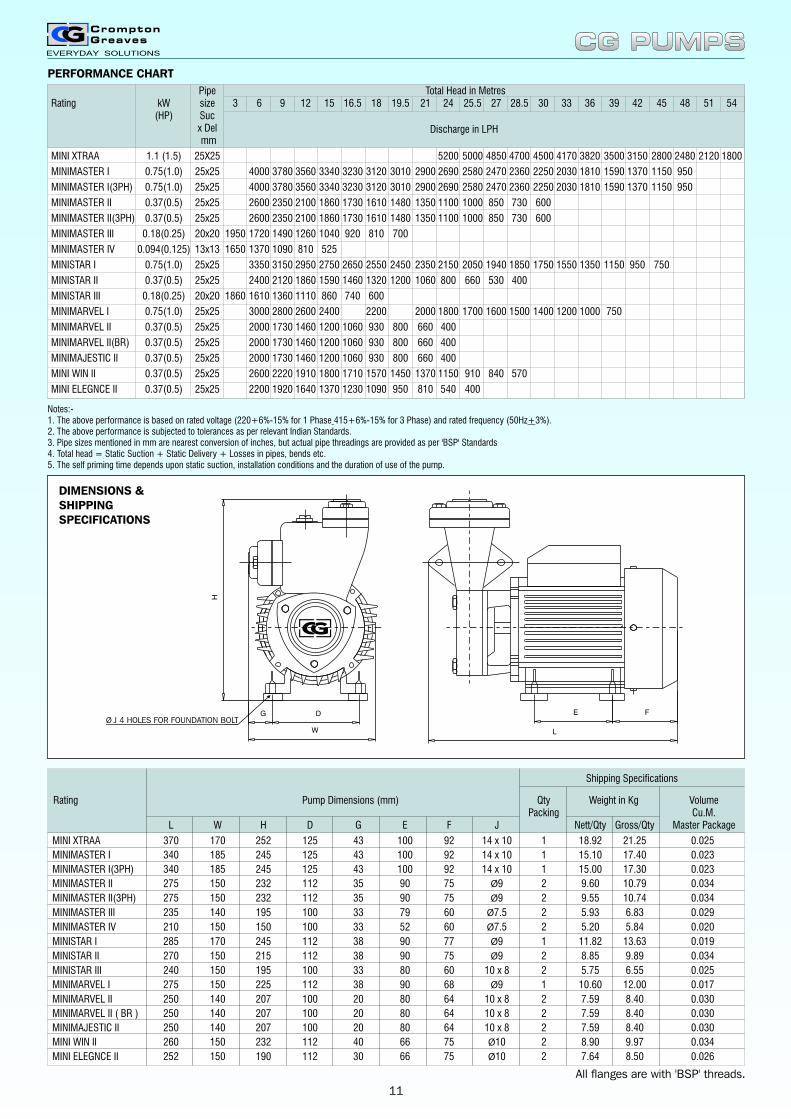
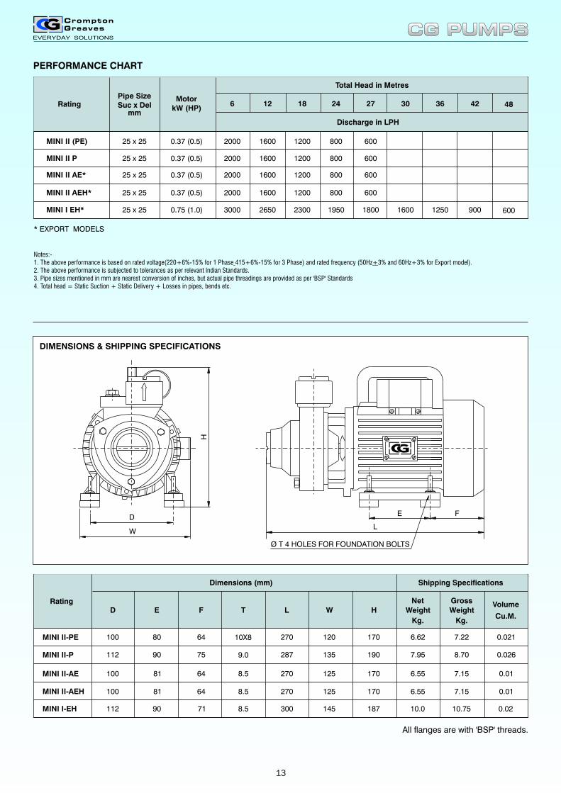
Pipe Total Head in MetresRating kW size 3 6 9 12 15 16.5 18 19.5 21 24 25.5 27 28.5 30 33 36 39 42 45 48 51 54
(HP) Sucx Del mm
MINI XTRAA 1.1 (1.5) 25X25 5200 5000 4850 4700 4500 4170 3820 3500 3150 2800 2480 2120 1800
MINIMASTER I 0.75(1.0) 25x25 4000 3780 3560 3340 3230 3120 3010 2900 2690 2580 2470 2360 2250 2030 1810 1590 1370 1150 950
MINIMASTER I(3PH) 0.75(1.0) 25x25 4000 3780 3560 3340 3230 3120 3010 2900 2690 2580 2470 2360 2250 2030 1810 1590 1370 1150 950
MINIMASTER II 0.37(0.5) 25x25 2600 2350 2100 1860 1730 1610 1480 1350 1100 1000 850 730 600
MINIMASTER II(3PH) 0.37(0.5) 25x25 2600 2350 2100 1860 1730 1610 1480 1350 1100 1000 850 730 600
MINIMASTER III 0.18(0.25) 20x20 1950 1720 1490 1260 1040 920 810 700
MINIMASTER IV 0.094(0.125) 13x13 1650 1370 1090 810 525
MINISTAR I 0.75(1.0) 25x25 3350 3150 2950 2750 2650 2550 2450 2350 2150 2050 1940 1850 1750 1550 1350 1150 950 750
MINISTAR II 0.37(0.5) 25x25 2400 2120 1860 1590 1460 1320 1200 1060 800 660 530 400
MINISTAR III 0.18(0.25) 20x20 1860 1610 1360 1110 860 740 600
MINIMARVEL I 0.75(1.0) 25x25 3000 2800 2600 2400 2200 2000 1800 1700 1600 1500 1400 1200 1000 750
MINIMARVEL II 0.37(0.5) 25x25 2000 1730 1460 1200 1060 930 800 660 400
MINIMARVEL II(BR) 0.37(0.5) 25x25 2000 1730 1460 1200 1060 930 800 660 400
MINIMAJESTIC II 0.37(0.5) 25x25 2000 1730 1460 1200 1060 930 800 660 400
MINI WIN II 0.37(0.5) 25x25 2600 2220 1910 1800 1710 1570 1450 1370 1150 910 840 570
MINI ELEGNCE II 0.37(0.5) 25x25 2200 1920 1640 1370 1230 1090 950 810 540 400
Discharge in LPH
Notes:-1. The above performance is based on rated voltage (220+6%-15% for 1 Phase 415+6%-15% for 3 Phase) and rated frequency (50Hz+3%).2. The above performance is subjected to tolerances as per relevant Indian Standards.3. Pipe sizes mentioned in mm are nearest conversion of inches, but actual pipe threadings are provided as per 'BSP' Standards4. Total head = Static Suction + Static Delivery + Losses in pipes, bends etc.5. The self priming time depends upon static suction, installation conditions and the duration of use of the pump.
DIMENSIONS &SHIPPINGSPECIFICATIONS
H
W
DG
L
E FØ J 4 HOLES FOR FOUNDATION BOLT
Rating Pump Dimensions (mm) Qty Weight in Kg VolumePacking Cu.M.
L W H D G E F J Nett/Qty Gross/Qty Master Package
MINI XTRAA 370 170 252 125 43 100 92 14 x 10 1 18.92 21.25 0.025
MINIMASTER I 340 185 245 125 43 100 92 14 x 10 1 15.10 17.40 0.023
MINIMASTER I(3PH) 340 185 245 125 43 100 92 14 x 10 1 15.00 17.30 0.023
MINIMASTER II 275 150 232 112 35 90 75 Ø9 2 9.60 10.79 0.034
MINIMASTER II(3PH) 275 150 232 112 35 90 75 Ø9 2 9.55 10.74 0.034
MINIMASTER III 235 140 195 100 33 79 60 Ø7.5 2 5.93 6.83 0.029
MINIMASTER IV 210 150 150 100 33 52 60 Ø7.5 2 5.20 5.84 0.020
MINISTAR I 285 170 245 112 38 90 77 Ø9 1 11.82 13.63 0.019
MINISTAR II 270 150 215 112 38 90 75 Ø9 2 8.85 9.89 0.034
MINISTAR III 240 150 195 100 33 80 60 10 x 8 2 5.75 6.55 0.025
MINIMARVEL I 275 150 225 112 38 90 68 Ø9 1 10.60 12.00 0.017
MINIMARVEL II 250 140 207 100 20 80 64 10 x 8 2 7.59 8.40 0.030
MINIMARVEL II ( BR ) 250 140 207 100 20 80 64 10 x 8 2 7.59 8.40 0.030
MINIMAJESTIC II 250 140 207 100 20 80 64 10 x 8 2 7.59 8.40 0.030
MINI WIN II 260 150 232 112 40 66 75 Ø10 2 8.90 9.97 0.034
MINI ELEGNCE II 252 150 190 112 30 66 75 Ø10 2 7.64 8.50 0.026
Shipping Specifications
CG PUMPSCG PUMPSPERFORMANCE CHART
All flanges are with 'BSP' threads.
11
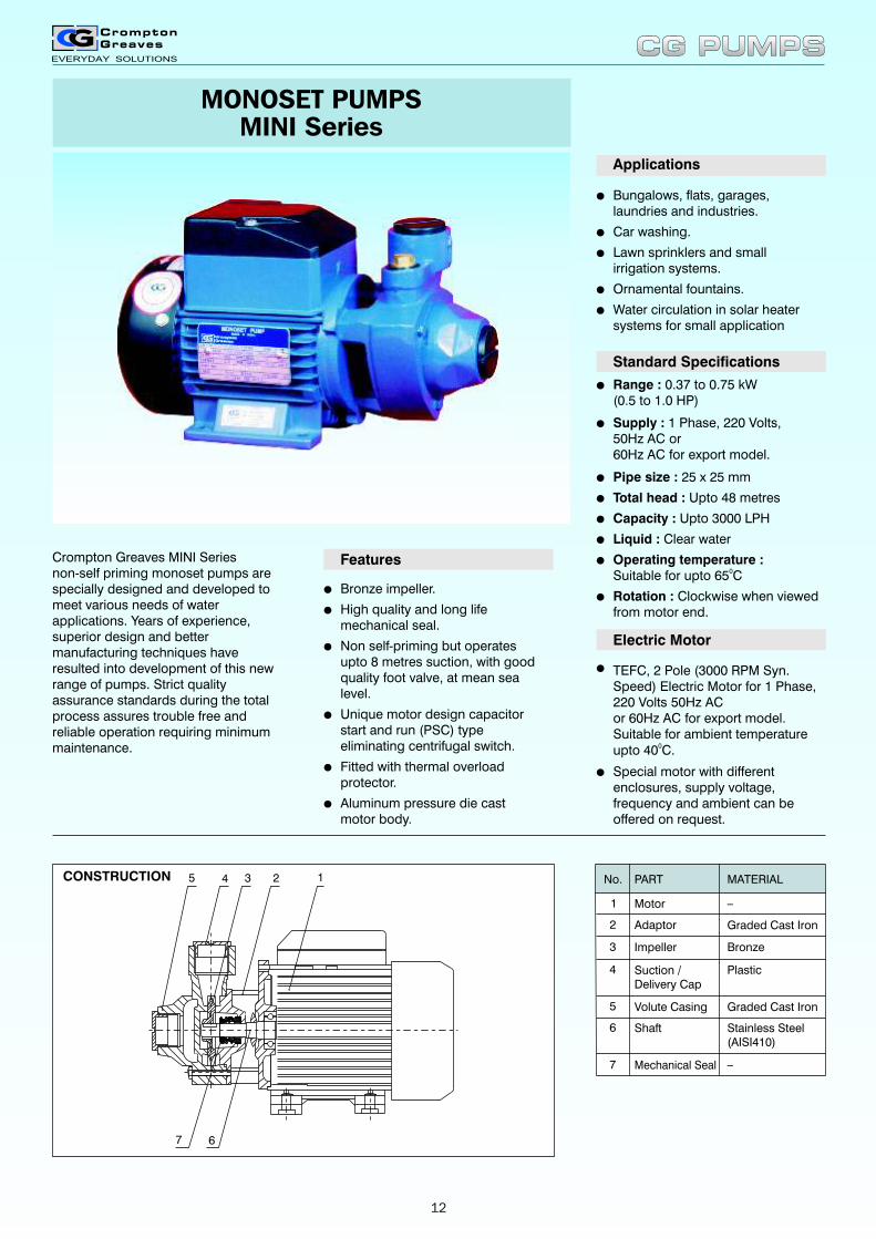
MONOSET PUMPSMINI Series
Crompton Greaves MINI Seriesnon-self priming monoset pumps are specially designed and developed to meet various needs of water applications. Years of experience, superior design and better manufacturing techniques have resulted into development of this new range of pumps. Strict quality assurance standards during the total process assures trouble free and reliable operation requiring minimum maintenance.
lBronze impeller.
lHigh quality and long life mechanical seal.
lNon self-priming but operatesupto 8 metres suction, with goodquality foot valve, at mean sealevel.
lUnique motor design capacitor start and run (PSC) typeeliminating centrifugal switch.
lFitted with thermal overloadprotector.
lAluminum pressure die castmotor body.
Features
lBungalows, flats, garages,laundries and industries.
lCar washing.
lLawn sprinklers and smallirrigation systems.
lOrnamental fountains.
lWater circulation in solar heater systems for small application
Applications
Standard Specifications
lRange : 0.37 to 0.75 kW(0.5 to 1.0 HP)
lSupply : 1 Phase, 220 Volts,50Hz AC or60Hz AC for export model.
lPipe size : 25 x 25 mm
lTotal head : Upto 48 metres
lCapacity : Upto 3000 LPH
lLiquid : Clear water
lOperating temperature :Suitable for upto 65 C0
lRotation : Clockwise when viewed from motor end.
Electric Motor
lTEFC, 2 Pole (3000 RPM Syn. Speed) Electric Motor for 1 Phase,220 Volts 50Hz ACor 60Hz AC for export model.Suitable for ambient temperature
0upto 40 C.
lSpecial motor with different enclosures, supply voltage, frequency and ambient can be offered on request.
CONSTRUCTION No.
4
3
2
1
Volute Casing
Mechanical Seal
Shaft
Impeller
Adaptor
Suction / Delivery Cap
Motor
PART
Bronze
Graded Cast Iron
Plastic
MATERIAL
_
Stainless Steel(AISI410)
_
Graded Cast Iron5
6
7
12345
67
CG PUMPSCG PUMPS
12
ED
W
H
L
F
Ø T 4 HOLES FOR FOUNDATION BOLTS
PERFORMANCE CHART
6 12 18 24 27 30 36 42 48
MINI II AE* 2000 1600 1200 800 600
MINI II AEH* 2000 1600 1200 800 600
MINI I EH* 3000 2650 2300 1950 1800 1600 1250 900 600
Rating
0.37 (0.5)
0.37 (0.5)
0.75 (1.0)
MotorkW (HP)
25 x 25
25 x 25
MINI II (PE) 2000 1600 1200 800 600
MINI II P 2000 1600 1200 800 600
0.37 (0.5)
0.37 (0.5)
25 x 25
25 x 25
25 x 25
Pipe Size Suc x Del
mm
Total Head in Metres
Discharge in LPH
* EXPORT MODELS
All flanges are with 'BSP' threads.
D E F L W H
Net
Weight
Kg.
Gross
Weight
Kg.
Volume
Cu.M.
Rating
Dimensions (mm) Shipping Specifications
T
100
100
112
81
80
90
64
64
75
270
270
287
125
120
135
170
170
190
6.55
6.62
7.95
7.15
7.22
8.70
0.01
0.021
0.026
100 81 64 270 125 170 6.55 7.15 0.01
MINI II-AE
MINI II-PE
MINI II-P
MINI II-AEH
MINI I-EH 112 90 71 300 145 187 10.0 10.75 0.02
8.5
10X8
9.0
8.5
8.5
CG PUMPSCG PUMPS
DIMENSIONS & SHIPPING SPECIFICATIONS
Notes:-1. The above performance is based on rated voltage(220+6%-15% for 1 Phase 415+6%-15% for 3 Phase) and rated frequency (50Hz+3% and 60Hz+3% for Export model).2. The above performance is subjected to tolerances as per relevant Indian Standards.3. Pipe sizes mentioned in mm are nearest conversion of inches, but actual pipe threadings are provided as per 'BSP' Standards4. Total head = Static Suction + Static Delivery + Losses in pipes, bends etc.
13
Standard Specifications
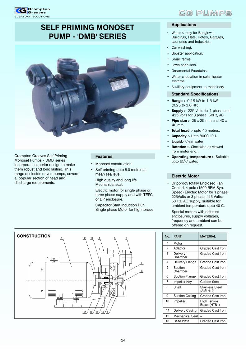
SELF PRIMING MONOSETPUMP - 'DMB' SERIES
Crompton Greaves Self Priming Monoset Pumps - 'DMB' series incorporate superior design to make them robust and long lasting. This range of electric driven pumps, covers a popular section of head and discharge requirements.
• Monoset construction.
• Self priming upto 8.0 metres at mean sea level.
� High quality and long life Mechanical seal.
� Electric motor for single phase or three phase supply and with TEFC or DP enclosure.
� Capacitor Start Induction Run Single phase Motor for high torque.
Features
• Water supply for Bunglows, Buildings, Flats, Hotels, Garages, Laundries and Industries.
• Car washing.
• Booster application.
• Small farms.
• Lawn sprinklers.
• Ornamental Fountains.
• Water circulation in solar heater systems.
• Auxiliary equipment to machinery.
Applications
• Range :- 0.18 kW to 1.5 kW(0.25 to 2.0 HP).
• Supply :- 225 Volts for 1 phase and 415 Volts for 3 phase, 50Hz, AC.
• Pipe size :- 25 x 25 mm and 40 x 40 mm.
• Total head :- upto 45 metres.
• Capacity :- Upto 8000 LPH.
• Liquid:- Clear water
• Rotation :- Clockwise as viewed from motor end.
• Operating temperature :- Suitable 0upto 65 C water.
Electric Motor
• Dripproof/Totally Enclosed Fan Cooled, 4 pole (1500 RPM Syn. Speed) Electric Motor for 1 phase, 225Volts or 3 phase, 415 Volts;50 Hz, AC supply, suitable for
0ambient temperature upto 40 C.
� Special motors with different enclosures, supply voltages, frequency and ambient can be offered on request.
CONSTRUCTION2 3 4 5
7
8
9
1 6
10111213
No.
2
1
Adaptor
Motor
PART MATERIAL
_
4
3
SuctionChamber
Impeller Key
Suction Flange
DeliveryChamber
Delivery Flange
Graded Cast Iron
Graded Cast Iron
Graded Cast Iron
Graded Cast Iron
Carbon Steel
Graded Cast Iron5
6
7
Shaft Stainless Steel(AISI 410)
8
Suction Casing Graded Cast Iron9
Impeller High TensileBrass (HTB1)
10
Delivery Casing Graded Cast Iron11
Mechanical Seal12
Base Plate13 Graded Cast Iron
_
CG PUMPSCG PUMPS
14
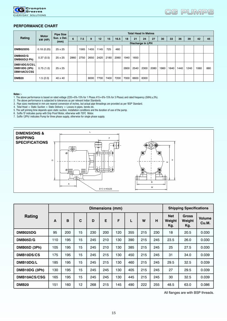
Notes :- 1. The above performance is based on rated voltage (220+6%-15% for 1 Phase 415+6%-15% for 3 Phase) and rated frequency (50Hz+3%).2. The above performance is subjected to tolerances as per relevant Indian Standards.3. Pipe sizes mentioned in mm are nearest conversion of inches, but actual pipe threadings are provided as per 'BSP' Standard.4. Total Head = Static Suction + Static Delivery + Losses in pipes, bends etc.5. The self priming time depends upon static suction, installation conditions and the duration of use of the pump. 6. Suffix 'D' indicates pump with Drip Proof Motor, otherwise with TEFC Motor.7. Suffix '(3Ph)' indicates Pump for three phase supply, otherwise for single phase supply.
6 7.5 9 12 15 16.5 18 21 24 27 30 33 36 39 42 45
DMB20 1.5 (2.0) 40 x 40 8000 7700 7400 7200 7000 6600 6300
Total Head In Metres
Discharge In LPH
RatingMotor
kW (HP)
Pipe Size
Suc. x Del.
(mm)
DMB05D/G
DMB05D(3 Ph)0.37 (0.5) 25 x 25 2860 2750 2650 2420 2180 2060
DMB10DG/S/CS/L
DMB10DG (3Ph)
DBM10ACS/CSG
0.75 (1.0) 25 x 25 1860 1640 14402800 2540 2300 1240 1060 880
DMB025DG 0.18 (0.25) 25 x 25 7251565 1455 1145 460
2080
1940 1650
PERFORMANCE CHART
A B C D E F L W H
Net
Weight
Kg.
Gross
Weight
Kg.
Volume
Cu.M.
DMB025DG 95 200 15 230 200 120 355 215 230 18 20.5 0.030
DMB05D/G 110 195 15 245 210 130 390 215 245 23.5 26.0 0.030
DMB05D (3Ph) 105 195 15 245 210 130 385 215 245 25 27.5 0.030
DMB10DS/CS 175 195 15 245 215 130 450 215 245 31 34.0 0.039
DMB10DG/L 185 195 15 245 215 130 460 215 245 29.5 32.5 0.039
DMB10DG (3Ph) 130 195 15 245 245 130 405 215 245 27 29.5 0.039
DMB10ACS/CSG 165 195 15 245 245 130 445 215 245 30 32.5 0.039
DMB20 151 160 12 268 215 145 490 222 255 48.5 63.0 0.086
Dimensions (mm) Shipping Specifications
Rating
All flanges are with BSP threads.
DIMENSIONS &SHIPPINGSPECIFICATIONS
A
F
L
W
B
E
HD
Ø 'C' 2 HOLES
CG PUMPSCG PUMPS
15
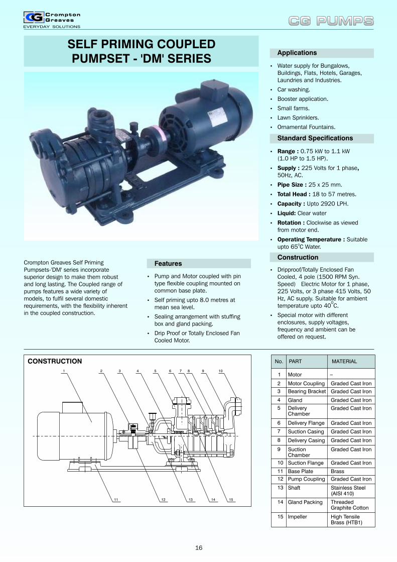
SELF PRIMING COUPLEDPUMPSET - 'DM' SERIES
Crompton Greaves Self Priming Pumpsets-'DM' series incorporate superior design to make them robust and long lasting. The Coupled range of pumps features a wide variety of models, to fulfil several domestic requirements, with the flexibility inherent in the coupled construction.
• Pump and Motor coupled with pin type flexible coupling mounted on common base plate.
• Self priming upto 8.0 metres at mean sea level.
• Sealing arrangement with stuffing box and gland packing.
• Drip Proof or Totally Enclosed Fan Cooled Motor.
Features
• Water supply for Bungalows, Buildings, Flats, Hotels, Garages, Laundries and Industries.
• Car washing.
• Booster application.
• Small farms.
• Lawn Sprinklers.
• Ornamental Fountains.
Applications
Standard Specifications
• Range : 0.75 kW to 1.1 kW(1.0 HP to 1.5 HP).
• Supply : 225 Volts for 1 phase, 50Hz, AC.
• Pipe Size : 25 x 25 mm.
• Total Head : 18 to 57 metres.
• Capacity : Upto 2920 LPH.
• Liquid: Clear water
• Rotation : Clockwise as viewed from motor end.
• Operating Temperature : Suitable 0upto 65 C Water.
Construction
• Dripproof/Totally Enclosed Fan Cooled, 4 pole (1500 RPM Syn. Speed) Electric Motor for 1 phase, 225 Volts, or 3 phase 415 Volts, 50 Hz, AC supply. Suitable for ambient
0temperature upto 40 C.
• Special motor with different enclosures, supply voltages, frequency and ambient can be offered on request.
CONSTRUCTION
1 2 3 4 5 6 7 8 9 10
11 12 13 1514
No.
2
1
Motor Coupling
Motor
PART MATERIAL
_
4
3
DeliveryChamber
Suction Casing
Delivery Flange
Bearing Bracket
Gland
Graded Cast Iron
Graded Cast Iron
Graded Cast Iron
Graded Cast Iron
Graded Cast Iron
Graded Cast Iron5
6
7
Delivery Casing Graded Cast Iron8
SuctionChamber
Graded Cast Iron9
Suction Flange Graded Cast Iron10
Base Plate Brass11
Pump Coupling Graded Cast Iron12
Shaft Stainless Steel(AISI 410)
13
Gland Packing ThreadedGraphite Cotton
14
Impeller High TensileBrass (HTB1)
15
CG PUMPSCG PUMPS
16

9 12 15 18 21 24 27 30 33 36 39 42 45 48 51 54 57
DM13T/G/
DM13TCS/
DM13TA
0.75 (1.0) 25 X 25 2260 2130 1990 1860 1710 1560 1410 1260 1080
DM15T 1.1 (1.5) 25 X 25 2920 2840 2740 2630 2520 2400 2280 2150 2020 1880 1730 1540
Total Head In metres
Discharge In LPH
RatingMotor
kW (HP)
Pipe Size
Suc. x Del.
(mm)
Notes :- 1. The above performance is based on rated voltage (220+6%-15% for 1 Phase) and rated frequency (50Hz+3%). 2. The above performance is subjected to tolerances as per relevant Indian Standards. 3. Pipe sizes mentioned in mm are nearest conversion of inches, but actual pipe threadings are provided as per 'BSP' Standard. 4. Total Head = Static Suction + Static Delivery + Losses in pipes, bends etc. 5. Self priming time depends upon static suction, installation conditions and the duration of use of the pump. 6. All above ratings are with Motor in Drip Proof enclosure except DM13TA and DM15T which are with Motor in TEFC enclosure.
PERFORMANCE CHART
DIMENSIONS & SHIPPING SPECIFICATIONS
A B
L
F
H
E
W
C1
C
Ø 'D' 4HOLES FOR FOUNDATION BOLTS
A B C C1 D E F L W H
Net
Weight
Kg.
Gross
Weight
Kg.
Volume
Cu.M.
DM13T/G 175 328 200 220 16 225 166 675 260 255 38.5 55.5 0.10
DM13TCS 185 328 200 220 16 225 166 690 260 255 39.5 56.5 0.10
DM13TA 165 340 200 220 16 225 166 670 260 255 40.5 57.5 0.10
DM15T 165 341 200 233 16 253 205 710 275 285 54 76.0 0.143
Rating
Dimensions (mm) Shipping Specifications
All flanges are with BSP threads.
CG PUMPSCG PUMPS
17
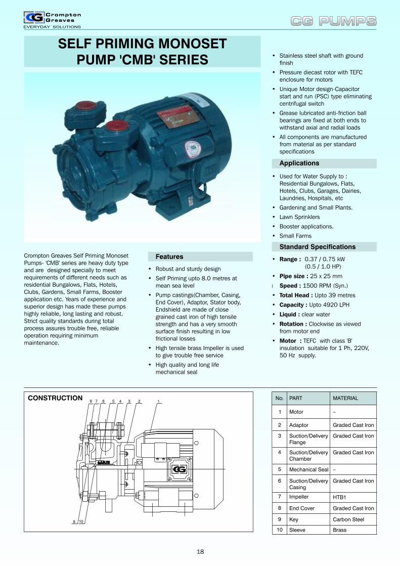
SELF PRIMING MONOSETPUMP 'CMB' SERIES
Crompton Greaves Self Priming Monoset Pumps- 'CMB' series are heavy duty type and are designed specially to meet requirements of different needs such as residential Bungalows, Flats, Hotels, Clubs, Gardens, Small Farms, Booster application etc. Years of experience and superior design has made these pumps highly reliable, long lasting and robust. Strict quality standards during total process assures trouble free, reliable operation requiring minimum maintenance.
• Robust and sturdy design
• Self Priming upto 8.0 metres at mean sea level
• Pump castings(Chamber, Casing, End Cover), Adaptor, Stator body, Endshield are made of close grained cast iron of high tensile strength and has a very smooth surface finish resulting in low frictional losses
• High tensile brass Impeller is used to give trouble free service
• High quality and long life mechanical seal
Features
• Used for Water Supply to : Residential Bungalows, Flats, Hotels, Clubs, Garages, Dairies, Laundries, Hospitals, etc
• Gardening and Small Plants.
• Lawn Sprinklers
• Booster applications.
• Small Farms
Applications
Standard Specifications
• Range : 0.37 / 0.75 kW(0.5 / 1.0 HP)
• Pipe size : 25 x 25 mm
l Speed : 1500 RPM (Syn.)
• Total Head : Upto 39 metres
• Capacity : Upto 4920 LPH
• Liquid : clear water
• Rotation : Clockwise as viewed from motor end
• Motor : TEFC with class 'B' insulation suitable for 1 Ph, 220V, 50 Hz supply.
CONSTRUCTION
• Stainless steel shaft with ground finish
• Pressure diecast rotor with TEFC enclosure for motors
• Unique Motor design-Capacitor start and run (PSC) type eliminating centrifugal switch
• Grease lubricated anti-friction ball bearings are fixed at both ends to withstand axial and radial loads
• All components are manufactured from material as per standard specifications
1234678
9
5
10
No.
2
1
Adaptor
Motor
PART MATERIAL
_
4
3
Mechanical Seal
Impeller
Suction/DeliveryCasing
Suction/DeliveryFlange
Suction/DeliveryChamber
Graded Cast Iron
Graded Cast Iron
Graded Cast Iron
Graded Cast Iron
HTB1
5
6
7
End Cover8
Key Carbon Steel9
Sleeve Brass10
_
Graded Cast Iron
CG PUMPSCG PUMPS
18
DIMENSIONS & SHIPPING SPECIFICATIONS
A
W
E
B
H
L
C D
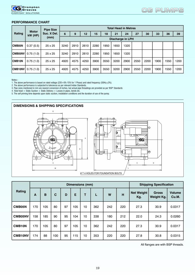
A B C D E T L W HNet Weight
Kg.
Gross
Weight Kg.
Volume
Cu.M.
CMB05N
CMB10N
170
170
105
105
80
80
97
97
105 10
105 10
362
362
242
242
220
220
27.3
27.3
30.9
30.9
0.0317
0.0317
CMB05NV
CMB10NV
158
174
185
88
90
100
95
95
104 10
115 10
338
353
180
220
212
220
22.0
27.8
24.3
30.8
0.0260
0.0315
Rating
Dimensions (mm) Shipping Specification
All flanges are with BSP threads.
6 9 12 15 18 21 24 27 30 33 36 39
0.37 (0.5) 25 x 25 3240 2910 2610 2280 1950 1650 1320CMB05N
CMB05NV
CMB10N
CMB10NV
0.75 (1.0)
0.75 (1.0)
0.75 (1.0)
25 x 25
25 x 25
25 x 25
3240
4920
4920
2910
4575
4575
2610
4250
4250
2280
3900
3900
1950
3550
3550
1650
3200
3200
1320
2900
2900
2550
2550
2200
2200
1900
1900
1550
1550
1200
1200
Rating Motor
kW (HP)
Pipe Size
Suc. X Del.
(mm)Discharge in LPH
Total Head in Metres
PERFORMANCE CHART
Ø T 4 HOLES FOR FOUNDATION BOLTS
CG PUMPSCG PUMPS
Notes:-1. The above performance is based on rated voltage (220+6%-15% for 1 Phase) and rated frequency (50Hz+3%).2. The above performance is subjected to tolerances as per relevant Indian Standards.3. Pipe sizes mentioned in mm are nearest conversion of inches, but actual pipe threadings are provided as per 'BSP' Standards4. Total head = Static Suction + Static Delivery + Losses in pipes, bends etc.5. The self priming time depends upon static suction, installation conditions and the duration of use of the pump.
19
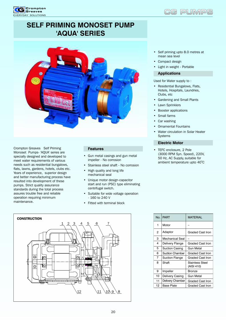
SELF PRIMING MONOSET PUMP'AQUA' SERIES
Crompton Greaves Self Priming Monoset Pumps- 'AQUA' series are specially designed and developed to meet water requirements of various needs such as residential bungalows, flats, lawns, gardens, hotels, clubs etc. Years of experience, superior design and better manufacturing process have resulted into development of these pumps. Strict quality assurance standards during the total process assures trouble free and reliable operation requiring minimum maintenance.
• Gun metal casings and gun metal impeller - No corrosion
• Stainless steel shaft - No corrosion
• High quality and long life mechanical seal
• Unique motor design-capacitor start and run (PSC) type eliminating centrifugal switch.
• Suitable for wide voltage operation - 160 to 240 V
• Fitted with terminal block
Features
Used for Water supply to :
• Residential Bungalows, Flats, Hotels, Hospitals, Laundries,Clubs, etc
• Gardening and Small Plants
• Lawn Sprinklers
• Booster applications
• Small farms
• Car washing
• Ornamental Fountains
• Water circulation in Solar Heater Systems
Applications
Electric Motor
• TEFC enclosure, 2 Pole(3000 RPM Syn. Speed), 220V,50 Hz, AC Supply, suitable for
0ambient temperature upto 40 C
No.
2
1
Adaptor
Motor
PART MATERIAL
_
4
3
Suction Casing
Suction Flange
Suction Chamber
Mechanical Seal
Delivery Flange
Stainless Steel(AISI 410)
Graded Cast Iron
Graded Cast Iron
Graded Cast Iron
Gun Metal5
6
7
Shaft8
Impeller Bronze9
Delivery Casing10
Graded Cast Iron11
Base Plate Graded Cast Iron12
_
Gun Metal
Graded Cast Iron
Delivery Chamber
• Self priming upto 8.0 metres at mean sea level
• Compact design
• Light in weight - Portable
CG PUMPSCG PUMPS
1 2 3 4 5 6 7
891012 11
CONSTRUCTION
20
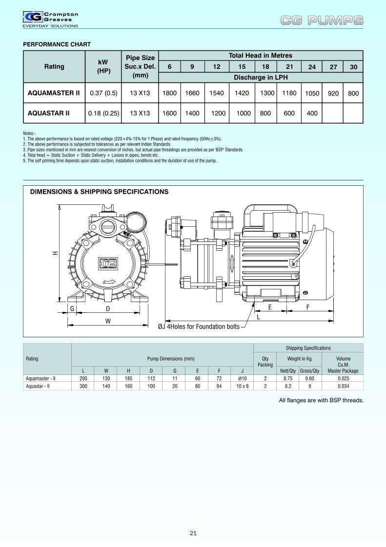
Rating Pump Dimensions (mm) Qty Weight in Kg VolumePacking Cu.M.
L W H D G E F J Nett/Qty Gross/Qty Master Package
Aquamaster - II 295 130 185 112 11 66 72 Ø10 2 8.75 9.60 0.025
Aquastar - II 300 140 160 100 20 80 64 10 x 8 2 8.2 9 0.034
Shipping Specifications
DIMENSIONS & SHIPPING SPECIFICATIONS
All flanges are with BSP threads.
6 9 12 15 18 21 24 27 30
AQUAMASTER II 0.37 (0.5) 13 X13 1800 1660 1540 1420 1300 1180 1050 920 800
AQUASTAR II 0.18 (0.25) 13 X13 1600 1400 1200 1000 800 600 400
Total Head in Metres
Discharge in LPH
Rating kW
(HP)
Pipe Size
Suc.x Del.
(mm)
PERFORMANCE CHART
ØJ 4Holes for Foundation bolts
H
WL
FEG D
CG PUMPSCG PUMPS
Notes:-1. The above performance is based on rated voltage (220+6%-15% for 1 Phase) and rated frequency (50Hz+3%).2. The above performance is subjected to tolerances as per relevant Indian Standards.3. Pipe sizes mentioned in mm are nearest conversion of inches, but actual pipe threadings are provided as per 'BSP' Standards4. Total head = Static Suction + Static Delivery + Losses in pipes, bends etc.5. The self priming time depends upon static suction, installation conditions and the duration of use of the pump.
DIMENSIONS & SHIPPING SPECIFICATIONS
21
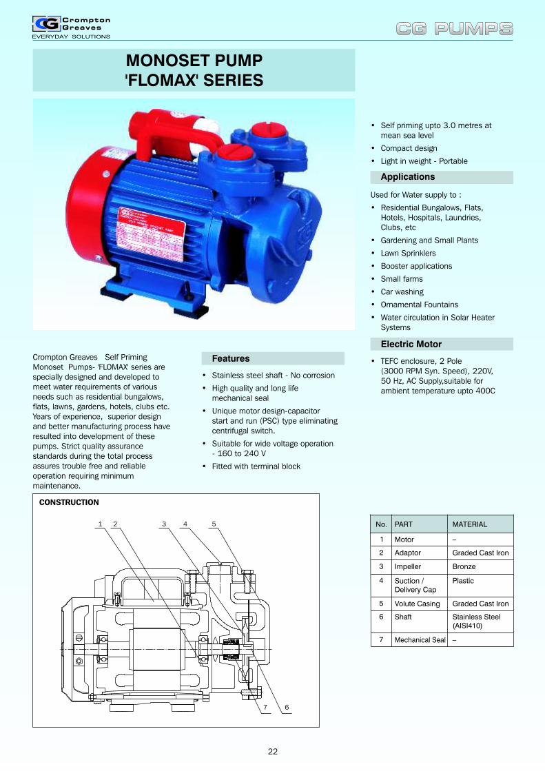
MONOSET PUMP'FLOMAX' SERIES
Crompton Greaves Self Priming Monoset Pumps- 'FLOMAX' series are specially designed and developed to meet water requirements of various needs such as residential bungalows, flats, lawns, gardens, hotels, clubs etc. Years of experience, superior design and better manufacturing process have resulted into development of these pumps. Strict quality assurance standards during the total process assures trouble free and reliable operation requiring minimum maintenance.
• Stainless steel shaft - No corrosion
• High quality and long life mechanical seal
• Unique motor design-capacitor start and run (PSC) type eliminating centrifugal switch.
• Suitable for wide voltage operation - 160 to 240 V
• Fitted with terminal block
Features
Used for Water supply to :
• Residential Bungalows, Flats, Hotels, Hospitals, Laundries,Clubs, etc
• Gardening and Small Plants
• Lawn Sprinklers
• Booster applications
• Small farms
• Car washing
• Ornamental Fountains
• Water circulation in Solar Heater Systems
Applications
Electric Motor
• TEFC enclosure, 2 Pole(3000 RPM Syn. Speed), 220V,50 Hz, AC Supply,suitable for ambient temperature upto 400C
• Self priming upto 3.0 metres at mean sea level
• Compact design
• Light in weight - Portable
No.
4
3
2
1
Volute Casing
Mechanical Seal
Shaft
Impeller
Adaptor
Suction / Delivery Cap
Motor
PART
Bronze
Graded Cast Iron
Plastic
MATERIAL
_
Stainless Steel(AISI410)
_
Graded Cast Iron5
6
7
CG PUMPSCG PUMPS
1 2 3 4 5
67
CONSTRUCTION
22
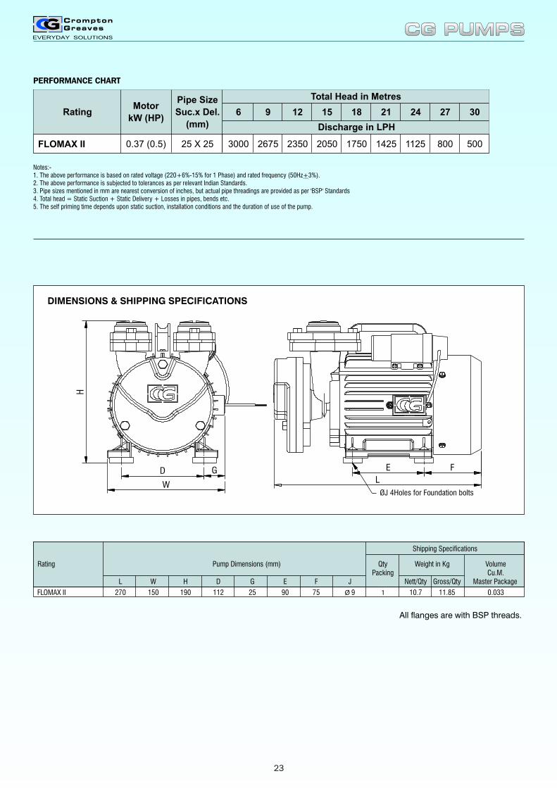
Rating Pump Dimensions (mm) Qty Weight in Kg VolumePacking Cu.M.
L W H D G E F J Nett/Qty Gross/Qty Master Package
FLOMAX II 270 150 190 112 25 90 75 Ø 9 1 10.7 11.85 0.033
Shipping Specifications
DIMENSIONS & SHIPPING SPECIFICATIONS
All flanges are with BSP threads.
E F
ØJ 4Holes for Foundation bolts
LW
H
D G
CG PUMPSCG PUMPS
PERFORMANCE CHART
6 9 12 15 18 21 24 27 30
FLOMAX II 0.37 (0.5) 25 X 25 3000 2675 2350 2050 1750 1425 1125 800 500
Rating Motor
kW (HP)
Pipe Size
Suc.x Del.
(mm)
Total Head in Metres
Discharge in LPH
Notes:-1. The above performance is based on rated voltage (220+6%-15% for 1 Phase) and rated frequency (50Hz+3%).2. The above performance is subjected to tolerances as per relevant Indian Standards.3. Pipe sizes mentioned in mm are nearest conversion of inches, but actual pipe threadings are provided as per 'BSP' Standards4. Total head = Static Suction + Static Delivery + Losses in pipes, bends etc.5. The self priming time depends upon static suction, installation conditions and the duration of use of the pump.
23
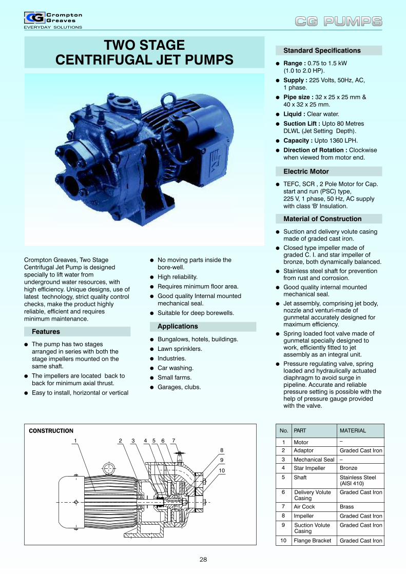
DIMENSIONS & SHIPPING SPECIFICATIONS
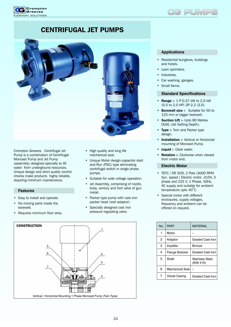
Crompton Greaves Centrifugal Jet Pump is a combination of Centrifugal Monoset Pump and Jet Pump (assembly) designed specially to lift water from underground resources. Unique design and strict quality control checks make products highly reliable, requiring minimum maintenance.
• Easy to install and operate.
• No moving parts inside the borewell.
• Requires minimum floor area.
Features
Applications
Standard Specifications
• Range :- 1 P-0.37 kW to 2.0 kW(0.5 to 2.0 HP) 3P-2.2 (3.0)
• Borewell size :- Suitable for 50 to 125 mm or bigger borewell.
• Suction Lift :- Upto 80 Metres DLWL (Jet Setting Depth).
• Type :- Twin and Packer type design.
• Installation :- Vertical or Horizontal mounting of Monoset Pump.
• Liquid :- Clear water.
• Rotation :- Clockwise when viewed from motor end.
• Residential bunglows, buildings and hotels.
• Lawn sprinklers.
• Industries.
• Car washing, garages.
• Small farms.
Electric Motor
• TEFC / DP, SCR, 2 Pole (3000 RPM Syn. speed ) Electric motor ,415V, 3 phase and 225 V, 1 Phase, 50Hz, AC supply and suitable for ambient
0temperature upto 40 C.
• Special motor with different enclosures, supply voltages, frequency and ambient can be offered on request.
• High quality and long life mechanical seal.
• Unique Motor design-capacitor start and Run (PSC) type eliminating centrifugal switch in single phase pumps.
• Suitable for wide voltage operation.
• Jet Assembly, comprising of nozzle, body, ventury and foot valve of gun metal.
• Packer type pump with cast iron packer head (well adaptor).
• Specially designed cast iron pressure regulating valve.
CENTRIFUGAL JET PUMPS
Vertical / Horizontal Mounting 1 Phase Monoset Pump (Twin Type)
1
2
3
4
5
6
7
CONSTRUCTION No.
4
3
2
1
Shaft
Volute Casing
Mechanical Seal
Impeller
Adaptor
Flange Bracket
Motor
PART
Bronze
Graded Cast Iron
Graded Cast Iron
MATERIAL
_
_
Graded Cast Iron
Stainless Steel(AISI 410)
5
6
7
CG PUMPSCG PUMPS
24
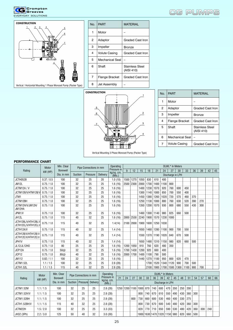
Adaptor
Motor
PART
Mechanical Seal
Flange Bracket
Shaft
Impeller
Volute Casing
Jet Assembly
Graded Cast Iron
MATERIAL
_
Bronze
Graded Cast Iron
Stainless Steel(AISI 410)
Graded Cast Iron
_
_
No.
2
1
4
3
5
6
7
8
1 2 3 4 5
6
7
8
Vertical / Horizontal Mounting 1 Phase Monoset Pump (Packer Type)
CONSTRUCTION
1
2
3
4
5
6
7
Vertical Mounting 3 Phase Monoset Pump (Packer Type)
CONSTRUCTION
Adaptor
Motor
PART
Shaft
Volute Casing
Mechanical Seal
Impeller
Flange Bracket
Graded Cast Iron
MATERIAL
_
Bronze
Graded Cast Iron
_
Graded Cast Iron
Stainless Steel(AISI 410)
No.
2
1
4
3
5
6
7
B
CG PUMPSCG PUMPS
PERFORMANCE CHART
25
A B C D E L W H
Net
Weight
Kg
Gross
Weight
Kg
Volume
in Cu.M.
Rating
Shipping SpecificationDimensions (mm)
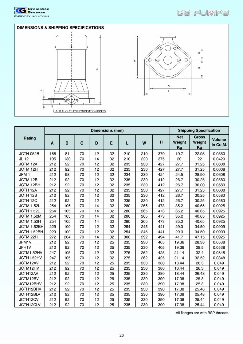
All flanges are with BSP threads.
DIMENSIONS & SHIPPING SPECIFICATIONS
H
E
W
A
L
CB
Ø 'D' 2HOLES FOR FOUNDATION BOLTS
JCTH 052B 188 81 70 12 32 210 210 370 19.7 22.95 0.0550
JL 12 195 130 70 14 32 210 220 375 20 22 0.0420
JCTM 12A 212 92 70 12 32 235 230 427 27.7 31.25 0.0608
JCTM 12H 212 92 70 12 32 235 230 427 27.7 31.25 0.0608
JPM 1 212 98 70 12 32 234 230 424 24.5 28.90 0.0608
JCTM 12B 212 92 70 12 32 235 230 412 26.7 30.25 0.0580
JCTM 12BH 212 92 70 12 32 235 230 412 26.7 30.00 0.0580
JCTH 12A 212 92 70 12 32 235 230 427 27.7 31.25 0.0608
JCTH 12B 212 92 70 12 32 235 230 412 26.7 30.25 0.0583
JCTH 12C 212 92 70 12 32 235 230 412 26.7 30.25 0.0583
JCTM 1.52L 254 105 70 14 32 280 265 473 35.2 40.65 0.0925
JCTH 1.52L 254 105 70 14 32 280 265 473 35.2 40.65 0.0925
JCTM 1.52M 254 105 70 14 32 280 265 473 35.2 40.65 0.0925
JCTM 1.52H 254 105 70 14 32 280 265 473 35.2 40.65 0.0925
JCTM 1.52BH 229 100 70 12 32 254 245 441 29.3 34.50 0.0909
JCTH 1.52BH 229 100 70 12 32 254 245 441 29.3 34.50 0.0909
JCTM 22H 272 204 70 14 32 300 292 494 41.7 47.15 0.0925
JPM1V 212 92 70 12 25 235 230 405 19.36 28.38 0.0538
JPH1V 212 92 70 12 25 235 230 405 19.36 28.5 0.0538
JCTM1.52HV 247 105 70 12 32 275 262 425 21.14 32.4 0.0848
JCTH1.52HV 247 105 70 12 32 275 262 425 21.14 32.52 0.0848
JCTM12AV 212 92 70 12 25 235 230 380 18.44 26.3 0.049
JCTM12HV 212 92 70 12 25 235 230 380 18.44 26.3 0.049
JCTH12AV 212 92 70 12 25 235 230 380 18.44 26.48 0.049
JCTM12BV 212 92 70 12 25 235 230 390 17.38 25.3 0.049
JCTM12BHV 212 92 70 12 25 235 230 390 17.38 25.3 0.049
JCTH12BHV 212 92 70 12 25 235 230 390 17.38 25.48 0.049
JCTH12BLV 212 92 70 12 25 235 230 390 17.38 25.48 0.049
JCTH12CV 212 92 70 12 25 235 230 390 17.38 25.44 0.049
JCTH12CLV 212 92 70 12 25 235 230 390 17.38 25.44 0.049
CG PUMPSCG PUMPS
26
A
L
G
H
W
EF
%%c 'D'B C
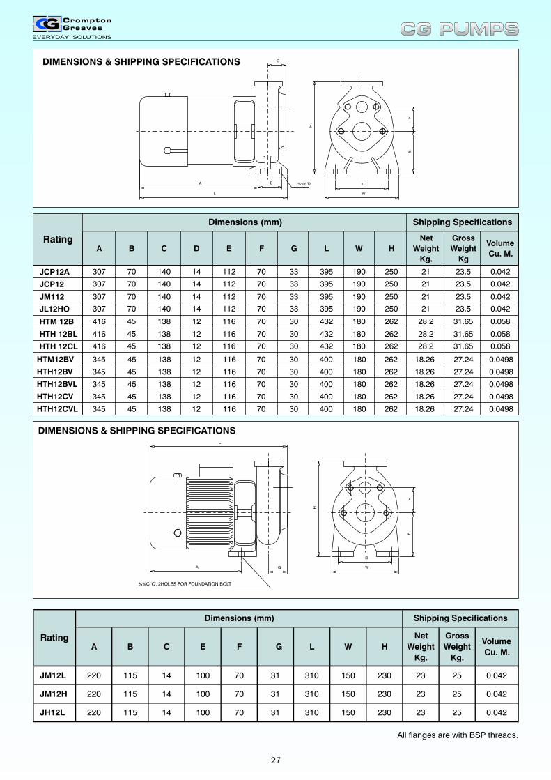
DIMENSIONS & SHIPPING SPECIFICATIONS
A B C D E F G L W H
Net
Weight
Kg.
Gross
Weight
Kg
Volume
Cu. M.
Dimensions (mm) Shipping Specifications
Rating
All flanges are with BSP threads.
A B C E F G L W H
Net
Weight
Kg.
Gross
Weight
Kg.
Volume
Cu. M.
JM12L 220 115 14 100 70 31 310 150 230 23 25 0.042
JM12H 220 115 14 100 70 31 310 150 230 23 25 0.042
JH12L 220 115 14 100 70 31 310 150 230 23 25 0.042
Dimensions (mm)
Rating
Shipping Specifications
A G
L
B
W
EF
H
%%C 'C', 2HOLES FOR FOUNDATION BOLT
DIMENSIONS & SHIPPING SPECIFICATIONS
HTH 12CL 416 45 138 12 116 70 30 432 180 262 28.2 31.65 0.058
HTH 12BL 416 45 138 12 116 70 30 432 180 262 28.2 31.65 0.058
HTM 12B 416 45 138 12 116 70 30 432 180 262 28.2 31.65 0.058
JL12HO 307 70 140 14 112 70 33 395 190 250 21 23.5 0.042
JM112 307 70 140 14 112 70 33 395 190 250 21 23.5 0.042
JCP12 307 70 140 14 112 70 33 395 190 250 21 23.5 0.042
JCP12A 307 70 140 14 112 70 33 395 190 250 21 23.5 0.042
HTM12BV 345 45 138 12 116 70 30 400 180 262 18.26 27.24 0.0498
HTH12BV 345 45 138 12 116 70 30 400 180 262 18.26 27.24 0.0498
HTH12BVL 345 45 138 12 116 70 30 400 180 262 18.26 27.24 0.0498
HTH12CV 345 45 138 12 116 70 30 400 180 262 18.26 27.24 0.0498
HTH12CVL 345 45 138 12 116 70 30 400 180 262 18.26 27.24 0.0498
CG PUMPSCG PUMPS
27
Standard Specifications
lRange : 0.75 to 1.5 kW (1.0 to 2.0 HP).
lSupply : 225 Volts, 50Hz, AC,1 phase.
lPipe size : 32 x 25 x 25 mm &40 x 32 x 25 mm.
lLiquid : Clear water.
lSuction Lift : Upto 80 Metres DLWL (Jet Setting Depth).
lCapacity : Upto 1360 LPH.
lDirection of Rotation : Clockwisewhen viewed from motor end.
Electric Motor
lTEFC, SCR , 2 Pole Motor for Cap.start and run (PSC) type,225 V, 1 phase, 50 Hz, AC supplywith class 'B' Insulation.
Material of Construction
lSuction and delivery volute casing made of graded cast iron.
lClosed type impeller made of graded C. I. and star impeller of bronze, both dynamically balanced.
lStainless steel shaft for prevention from rust and corrosion.
lGood quality internal mounted mechanical seal.
lJet assembly, comprising jet body, nozzle and venturi-made ofgunmetal accurately designed for maximum efficiency.
lSpring loaded foot valve made of gunmetal specially designed to work, efficiently fitted to jet assembly as an integral unit.
lPressure regulating valve, springloaded and hydraulically actuateddiaphragm to avoid surge inpipeline. Accurate and reliablepressure setting is possible with thehelp of pressure gauge providedwith the valve.
TWO STAGECENTRIFUGAL JET PUMPS
Crompton Greaves, Two Stage Centrifugal Jet Pump is designed specially to lift water from underground water resources, with high efficiency. Unique designs, use of latest technology, strict quality control checks, make the product highly reliable, efficient and requires minimum maintenance.
lNo moving parts inside thebore-well.
lHigh reliability.
lRequires minimum floor area.
lGood quality Internal mounted mechanical seal.
lSuitable for deep borewells.
Applications
lBungalows, hotels, buildings.
lLawn sprinklers.
lIndustries.
lCar washing.
lSmall farms.
lGarages, clubs.
lThe pump has two stages arranged in series with both the stage impellers mounted on the same shaft.
lThe impellers are located back to back for minimum axial thrust.
lEasy to install, horizontal or vertical
Features
No.
2
1
Adaptor
Motor
PART MATERIAL
_
4
3
Shaft
Air Cock
Delivery VoluteCasing
Mechanical Seal
Star Impeller
Graded Cast Iron
Bronze
Graded Cast Iron
Brass
5
6
7
Impeller8
Suction VoluteCasing
Graded Cast Iron9
Flange Bracket10
_
Stainless Steel(AISI 410)
Graded Cast Iron
Graded Cast Iron
1 2 3 6 7
8
9
4
10
5
CG PUMPSCG PUMPS
CONSTRUCTION
28
All flanges are with 'BSP' threads.
Notes :-
1. The above performance is based on rated voltage (220+6%-15% for 1 Phase) and rated frequency (50Hz+3%).
2. The above performance is subjected to tolerances as per applicable standards.
3. Pipe sizes mentioned in mm are nearest conversion of inches, but actual pipe threadings are provided as per 'BSP' standard.
4. Please ensure Minimum Submergence of Jet assembly to 2 meters or 10% of Jet setting Depth (Suction Lift) whichever is
more from steady water level for above performance.
5. Operating pressure indicated is minimum pressure required for successful operation of Jet Pump.
* 6. DLWL means depth to low water level. DLWL is also known as Jet Setting depth or suction lift (i.e. Vertical distance from
monoset pump to steady water level).
7. For horizontal pump the performance given is applicable if it is installed within 1.5 meters from the borewell.
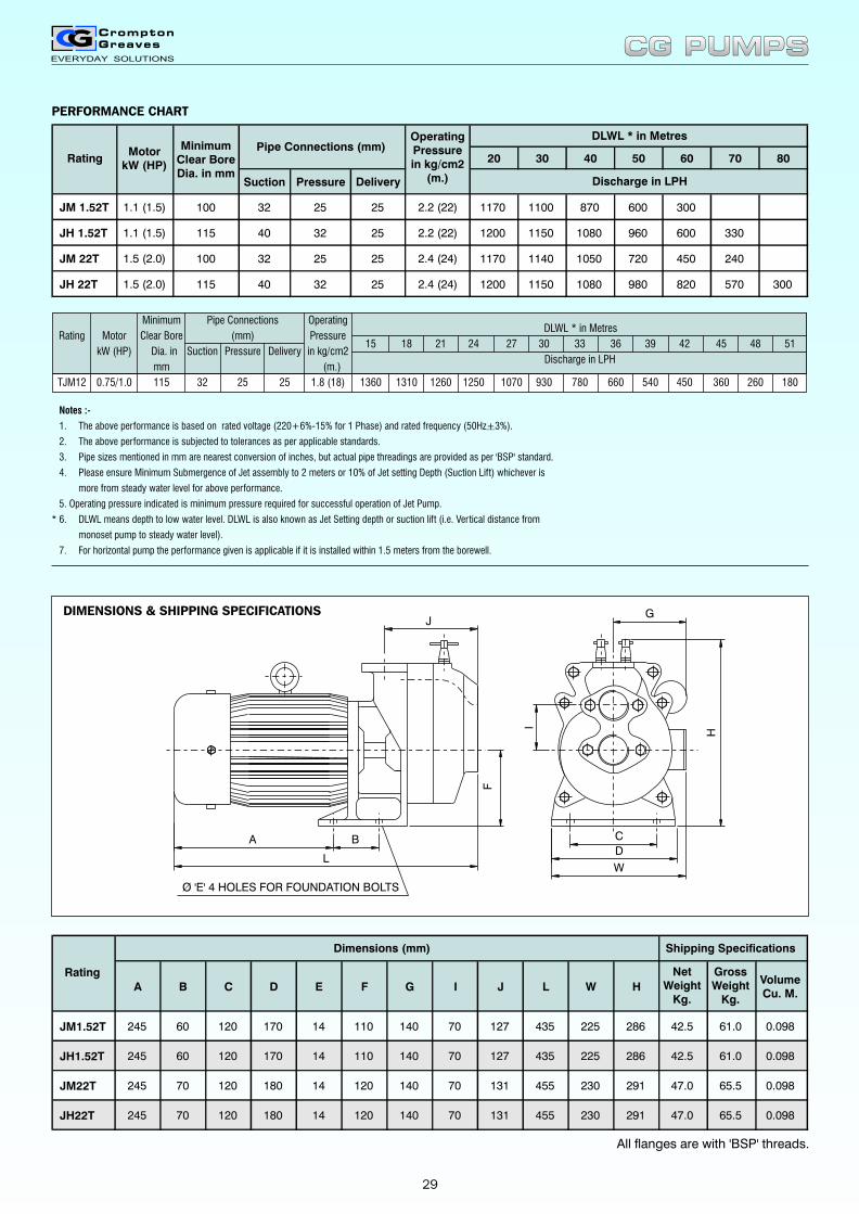
PERFORMANCE CHART
WL
A C
H
F
B
J
I
D
G
Ø 'E' 4 HOLES FOR FOUNDATION BOLTS
A B C D E F G I J L W H
NetWeight
Kg.
GrossWeight
Kg.
VolumeCu. M.
JM1.52T 245 60 120 170 14 110 140 70 127 435 225 286 42.5 61.0 0.098
JH1.52T 245 60 120 170 14 110 140 70 127 435 225 286 42.5 61.0 0.098
JM22T 245 70 120 180 14 120 140 70 131 455 230 291 47.0 65.5 0.098
JH22T 245 70 120 180 14 120 140 70 131 455 230 291 47.0 65.5 0.098
Rating
Dimensions (mm) Shipping Specifications
20 30 40 50 60 70 80
Suction Pressure Delivery
JM 1.52T 1.1 (1.5) 100 32 25 25 2.2 (22) 1170 1100 870 600 300
JH 1.52T 1.1 (1.5) 115 40 32 25 2.2 (22) 1200 1150 1080 960 600 330
JM 22T 1.5 (2.0) 100 32 25 25 2.4 (24) 1170 1140 1050 720 450 240
JH 22T 1.5 (2.0) 115 40 32 25 2.4 (24) 1200 1150 1080 980 820 570 300
OperatingPressurein kg/cm2
(m.)
DLWL * in Metres
Discharge in LPH
RatingMotor
kW (HP)
MinimumClear BoreDia. in mm
Pipe Connections (mm)
Rating Motor Clear Bore (mm) Pressure15 18 21 24 27 30 33 36 39 42 45 48 51
kW (HP) Dia. in Suction Pressure Delivery in kg/cm2Discharge in LPH
mm (m.)
TJM12 0.75/1.0 115 32 25 25 1.8 (18) 1360 1310 1260 1250 1070 930 780 660 540 450 360 260 180
Minimum Pipe Connections OperatingDLWL * in Metres
CG PUMPSCG PUMPS
DIMENSIONS & SHIPPING SPECIFICATIONS
29
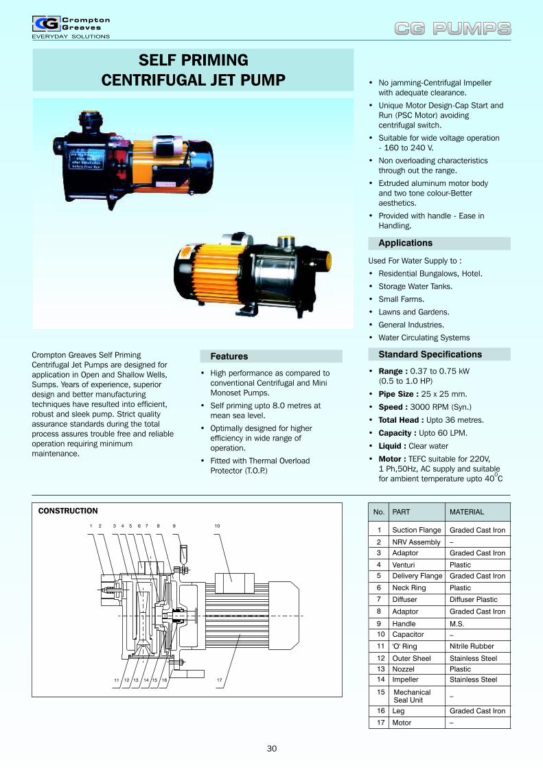
Crompton Greaves Self Priming Centrifugal Jet Pumps are designed for application in Open and Shallow Wells, Sumps. Years of experience, superior design and better manufacturing techniques have resulted into efficient, robust and sleek pump. Strict quality assurance standards during the total process assures trouble free and reliable operation requiring minimum maintenance.
• High performance as compared to conventional Centrifugal and Mini Monoset Pumps.
• Self priming upto 8.0 metres at mean sea level.
• Optimally designed for higher efficiency in wide range of operation.
• Fitted with Thermal Overload Protector (T.O.P.)
Features
Applications
Used For Water Supply to :
• Residential Bungalows, Hotel.
• Storage Water Tanks.
• Small Farms.
• Lawns and Gardens.
• General Industries.
• Water Circulating Systems
Standard Specifications
• Range : 0.37 to 0.75 kW(0.5 to 1.0 HP)
• Pipe Size : 25 x 25 mm.
• Speed : 3000 RPM (Syn.)
• Total Head : Upto 36 metres.
• Capacity : Upto 60 LPM.
• Liquid : Clear water
• Motor : TEFC suitable for 220V,1 Ph,50Hz, AC supply and suitable
0for ambient temperature upto 40 C
• No jamming-Centrifugal Impeller with adequate clearance.
• Unique Motor Design-Cap Start and Run (PSC Motor) avoiding centrifugal switch.
• Suitable for wide voltage operation - 160 to 240 V.
• Non overloading characteristics through out the range.
• Extruded aluminum motor body and two tone colour-Better aesthetics.
• Provided with handle - Ease in Handling.
SELF PRIMINGCENTRIFUGAL JET PUMP
1 2 3 4 5 6 7 8 9 10
11 12 13 14 15 16 17
No.
2
1
NRV Assembly
Suction Flange
PART MATERIAL
Graded Cast Iron
4
3
Delivery Flange
Diffuser
Neck Ring
Adaptor
Venturi
Graded Cast Iron
_
Plastic
Plastic
Diffuser Plastic
Graded Cast Iron5
6
7
Adaptor Graded Cast Iron8
Handle M.S.9
Capacitor10
'O' Ring Nitrile Rubber11
Outer Sheel Stainless Steel12
Nozzel Plastic13
Impeller Stainless Steel14
MechanicalSeal Unit
15
Leg16
Motor17
_
_
_Graded Cast Iron
CONSTRUCTION
CG PUMPSCG PUMPS
30
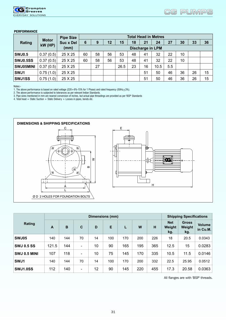
PERFORMANCE
Notes:-1. The above performance is based on rated voltage (220+6%-15% for 1 Phase) and rated frequency (50Hz+3%).2. The above performance is subjected to tolerances as per relevant Indian Standards.3. Pipe sizes mentioned in mm are nearest conversion of inches, but actual pipe threadings are provided as per 'BSP' Standards4. Total head = Static Suction + Static Delivery + Losses in pipes, bends etc.
C
Ø D 2 HOLES FOR FOUNDATION BOLTS
W
B
A
L
E
H
DIMENSIONS & SHIPPING SPECIFICATIONS
A B C D E L W H
Net
Weight
kg.
Gross
Weight
kg.
Volume
in Cu.M.
SWJ05 140 144 70 14 100 170 200 226 18 20.5 0.0343
SWJ 0.5 SS 121.5 144 - 10 90 165 195 365 12.5 15 0.0283
SWJ 0.5 MINI 107 118 - 10 75 145 170 335 10.5 11.5 0.0146
SWJ1 140 144 70 14 100 170 200 332 22.5 25.95 0.0512
SWJ1.0SS 112 140 - 12 90 145 220 455 17.3 20.58 0.0363
Rating
Dimensions (mm) Shipping Specifications
6 9 12 15 18 21 24 27 30 33 36
SWJ0.5 0.37 (0.5) 25 X 25 60 58 56 53 48 41 32 22 10
SWJ0.5SS 0.37 (0.5) 25 X 25 60 58 56 53 48 41 32 22 10
SWJ05MINI 0.37 (0.5) 25 X 25 27 26.5 23 16 10.5 5.5
SWJ1 0.75 (1.0)
0.75 (1.0)
25 X 25 51 50 46 36 26 15
SWJ1SS 25 X 25 51 50 46 36 26 15
Total Head in Metres
Discharge in LPM
RatingMotor
kW (HP)
Pipe Size
Suc x Del
(mm)
CG PUMPSCG PUMPS
All flanges are with 'BSP' threads.
31
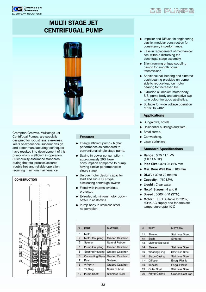
MULTI STAGE JETCENTRIFUGAL PUMP
Crompton Greaves, Multistage Jet Centrifugal Pumps, are specially designed for robustness, sleekness. Years of experience, superior design and better manufacturing techniques have resulted into development of this pump which is efficient in operation. Strict quality assurance standards during the total process assures trouble free and reliable operation requiring minimum maintenance.
1
234567
89
13
14
15
16
171819
201112
10
lEnergy efficient pump - higher performance as compared to conventional single stage pump.
lSaving in power consumption - approximately 20% lower consumption compared to pump having similar performance in single stage.
lUnique motor design capacitorstart and run (PSC) typeeliminating centrifugal switch
lFitted with thermal overload protector.
lExtruded aluminium motor body - better in aesthetics.
lPump body in stainless steel -no corrosion.
Features
Applications
lBungalows, hotels.
lResidential buildings and flats.
lSmall farms.
lCar washing.
lLawn sprinklers.
Standard Specifications
lRange : 0.75 / 1.1 kW(1.0 / 1.5 HP)
lPipe Size : 32 x 25 x 25 mm
lMin. Bore Well Dia. : 100 mm
lDLWL : 30 to 72 metres.
lCapacity : 750 LPH.
lLiquid : Clear water
lNo.of Stages : 4 and 6
lSpeed : 3000 RPM (SYN).
lMotor : TEFC Suitable for 220V,50Hz, AC supply and for ambient
0temperature upto 40 C
lImpeller and Diffuser in engineeringplastic, modular construction forconsistency in performance.
lEase in replacement of mechanical seal without disturbing the centrifugal stage assembly.
lSilent running unique coupling design for smooth power transmission.
lAdditional ball bearing and sintered bush bearing provided on pump side to reduce load on motor bearing for increased life.
lExtruded aluminium motor body, S.S. pump body and attractive two tone colour for good aesthetics.
lSuitable for wide voltage operation of 160 to 240V.
No.
2
1
Motor Coupling
Motor
PART MATERIAL
_
4
3
Bearing Housing
Bush
Connecting Piece
Spacer
Pump Coupling
Graded Cast Iron
Graded Cast Iron5
6
7
Adaptor8
'O' Ring Nitrile Rubber9
Pump Shaft Stainless Steel10
Natural Rubber
Graded Cast Iron
Sintered
Graded Cast Iron
Graded Cast Iron
Sleeve Stainless Steel11
No. PART MATERIAL
Bush_
Wearing Ring
Diffuser
Stage Casing
Mechanical Seal
Sleeve
Stainless Steel
Impeller
Outer Shell Stainless Steel
Pump Casing Graded Cast Iron
Stainless Steel
Stainless Steel
Engg. Plastic
Engg. Plastic
13
12
15
14
16
17
18
19
20
Sintered
CG PUMPSCG PUMPS
CONSTRUCTION
32
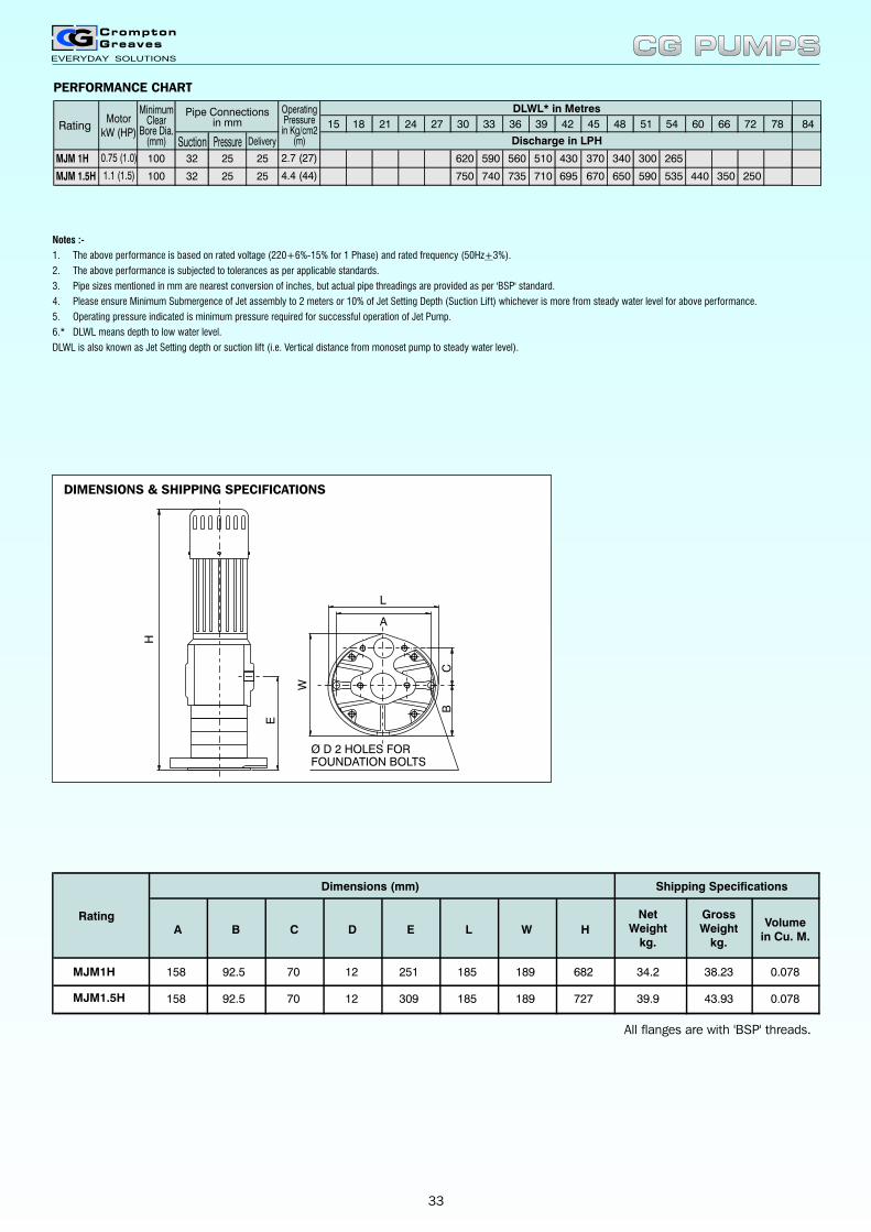
PERFORMANCE CHART
All flanges are with 'BSP' threads.
Notes :-
1. The above performance is based on
2. The above performance is subjected to tolerances as per applicable standards.
3. Pipe sizes mentioned in mm are nearest conversion of inches, but actual pipe threadings are provided as per 'BSP' standard.
4. Please ensure Minimum Submergence of Jet assembly to 2 meters or 10% of Jet Setting Depth (Suction Lift) whichever is more from steady water level for above performance.
5. Operating pressure indicated is minimum pressure required for successful operation of Jet Pump.
6.* DLWL means depth to low water level.
DLWL is also known as Jet Setting depth or suction lift (i.e. Vertical distance from monoset pump to steady water level).
rated voltage (220+6%-15% for 1 Phase) and rated frequency (50Hz+3%).
A B C D E L W H
NetWeight
kg.
GrossWeight
kg.
Volumein Cu. M.
MJM1H 158 92.5 70 12 251 185 189 682 34.2 38.23 0.078
MJM1.5H 158 92.5 70 12 309 185 189 727 39.9 43.93 0.078
Rating
Dimensions (mm) Shipping Specifications
H
Ø D 2 HOLES FORFOUNDATION BOLTS
E
W
CB
L
A
DIMENSIONS & SHIPPING SPECIFICATIONS
CG PUMPSCG PUMPS
33
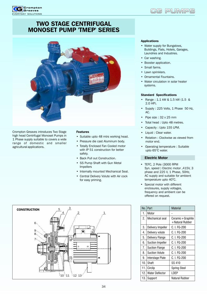
TWO STAGE CENTRIFUGALMONOSET PUMP 'TMEP' SERIES
Crompton Greaves introduces Two Stage high head Centrifugal Monoset Pumps in 1 Phase supply suitable to covers a wide range of domestic and smaller agricultural applications.
Features
• Suitable upto 48 mtrs working head.
• Pressure die cast Aluminum body.
• Totally Enclosed Fan Cooled motor with IP 51 construction for better safety.
• Back Pull out Construction.
• SS Pump Shaft with Gun Metal Impellers
• Internally mounted Mechanical Seal.
• Central Delivery Volute with Air cock for easy priming.
Applications
• Water supply for Bungalows, Buildings, Flats, Hotels, Garages, Laundries and Industries.
• Car washing.
• Booster application.
• Small farms.
• Lawn sprinklers.
• Ornamental Fountains.
• Water circulation in solar heater systems.
Standard Specifications
• Range : 1.1 kW & 1.5 kW (1.5 & 2.0 HP).
• Supply : 225 Volts, 1 Phase 50 Hz, AC.
• Pipe size : 32 x 25 mm
• Total head : Upto 48 metres.
• Capacity : Upto 155 LPM.
• Liquid : Clear water.
• Rotation : Clockwise as viewed from motor end.
• Operating temperature : Suitable upto 65°C water.
Electric Motor
• TEFC, 2 Pole (3000 RPM Syn. speed ) Electric motor ,415V, 3 phase and 225 V, 1 Phase, 50Hz, AC supply and suitable for ambient
0temperature upto 40 C.
• Special motor with different enclosures, supply voltages, frequency and ambient can be offered on request.
CG PUMPSCG PUMPS
CONSTRUCTION No. Part Material
1. Motor -
2. Mechanical seal Ceramic+Graphite+Natural Rubber
3. Delivery Impeller C. I. FG-200
4. Delivery volute C. I. FG-200
5. Delivery Flange C. I. FG-200
6. Suction Impeller C. I. FG-200
7. Suction Flange C. I. FG-200
8. Suction Volute C. I. FG-200
9. Interstage Plate C. I. FG-200
10. Shaft SS 410
11. Circlip Spring Steel
12. Water Deflector LDEP
13. Support Natural Rubber
34
5
6
98
7
10 11 12 13
4
3
12
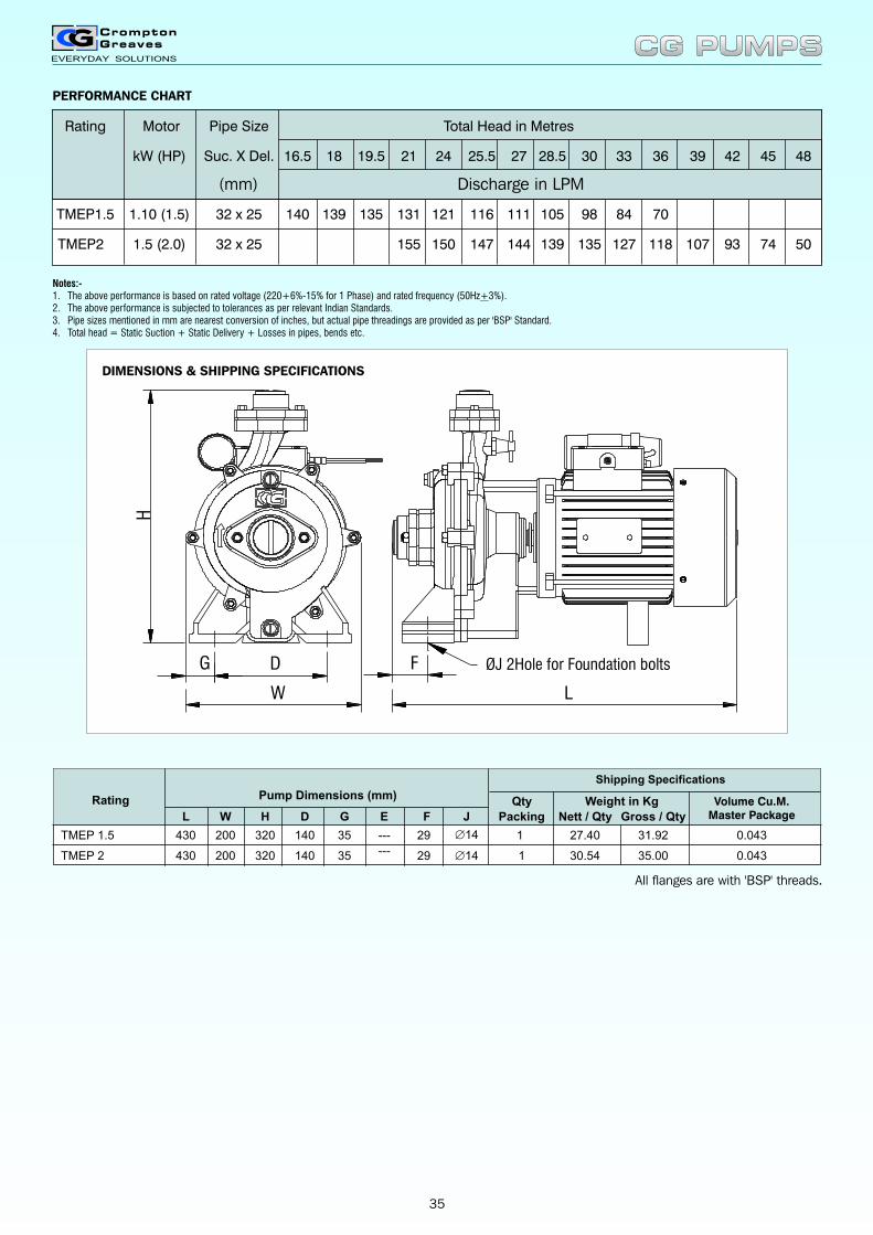
Notes:-1. The above performance is based on2. The above performance is subjected to tolerances as per relevant Indian Standards.3. Pipe sizes mentioned in mm are nearest conversion of inches, but actual pipe threadings are provided as per 'BSP' Standard.4. Total head = Static Suction + Static Delivery + Losses in pipes, bends etc.
rated voltage (220+6%-15% for 1 Phase) and rated frequency (50Hz+3%).
Volume Cu.M.Master Package
0.043
E F J
--- 29 ?14
Rating
L W H D G
0.043--- 29 ?14
Qty
1
Packing
1TMEP 1.5 430 200 320 140 35
TMEP 2 430 200 320 140 35
Pump Dimensions (mm)
Nett / Qty Gross / Qty
30.54 35.00
27.40 31.92
Weight in Kg
Shipping Specifications
CG PUMPSCG PUMPS
PERFORMANCE CHART
ØJ 2Hole for Foundation boltsG D
H
W L
F
DIMENSIONS & SHIPPING SPECIFICATIONS
All flanges are with 'BSP' threads.
35
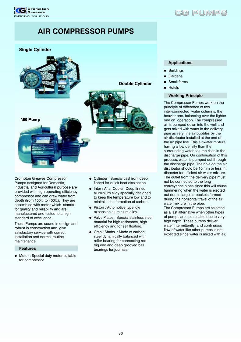
AIR COMPRESSOR PUMPS
Applications
lBuildings
lGardens
lSmall farms
lHotels
Working Principle
The Compressor Pumps work on the principle of difference of twointer-connected water columns, the heavier one, balancing over the lighter one on operation. The compressed air is pumped down into the well and gets mixed with water in the delivery pipe as very fine air bubbles by theair-distributor installed at the end of the air pipe line. This air-water mixture having a low density than the surrounding water column rises in the discharge pipe. On continuation of this process, water is pumped out through the discharge pipe. The hole on the air distributor should be 10 mm or less in diameter for efficient air water mixture. The outlet from the delivery pipe must not be connected to the long conveyance pipes since this will cause hammering when the water is ejected out due to large air pockets formed during the horizontal travel of the air water mixture in the pipe. The Compressor Pumps are selected as a last alternative when other types of pumps are not suitable due to very high depth. These pumps deliver water intermittently and continuous flow of water like other pumps is not expected since water is mixed with air.
Crompton Greaves Compressor Pumps designed for Domestic, Industrial and Agricultural purpose are provided with high operating efficiency compressor and can draw water from depth (from 100ft. to 400ft.). They are assembled with motor which stands for quality and reliability and are manufactured and tested to a high standard of excellence.
These Pumps are sound in design and robust in construction and give satisfactory service with correct installation and normal routine maintenance.
lCylinder : Special cast iron, deep finned for quick heat dissipation.
lInter / After Cooler: Deep finned aluminium alloy specially designed to keep the temperature low and to minimise the formation of carbon.
lPiston : Automotive type low expansion aluminium alloy.
lValve Plates : Special stainless steel material for high resistance, highefficiency and for self floating.
lCrank Shafts : Made of carbon steel dynamically balanced with roller bearing for connecting rod big end and deep grooved ball bearings for journals.Features
lMotor : Special duty motor suitablefor compressor.
Single Cylinder
Double Cylinder
MB Pump
CG PUMPSCG PUMPS
36
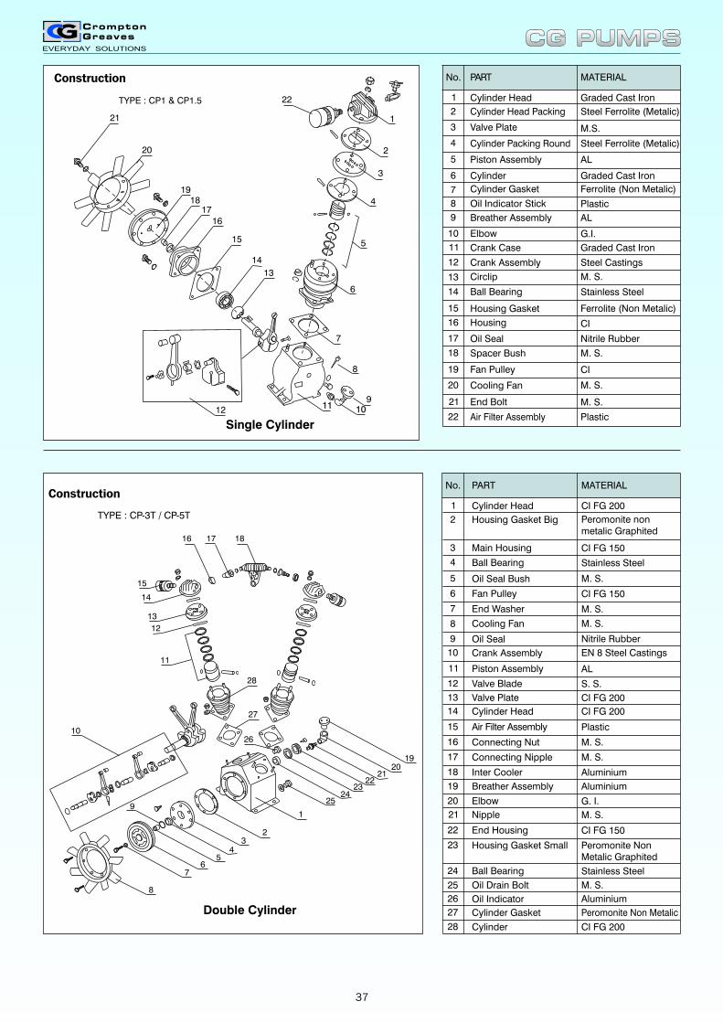
Construction
1011
Single Cylinder
8
912
1
2
3
4
5
6
7
22
21
20
1918
1716
15
14
13
TYPE : CP1 & CP1.5
Double Cylinder
TYPE : CP-3T / CP-5T
26
9
8
16 17 18
15
14
13
12
11
10
28
27
76
54
32
1
2524
2322
2120
19
Oil Seal Bush
End Washer
Fan Pulley
Main Housing
Ball Bearing
Cooling Fan
Oil Seal
Crank Assembly
Piston Assembly
Valve Blade
Valve Plate
Cylinder Head
Air Filter Assembly
Connecting Nut
Connecting Nipple
Inter Cooler
Breather Assembly
Elbow
Nipple
End Housing
Housing Gasket Small
Ball Bearing
Oil Drain Bolt
M. S.
Nitrile Rubber
Stainless Steel
M. S.
M. S.
S. S.
CI FG 150
M. S.
G. I.
Aluminium
M. S.
M. S.
CI FG 150
Stainless Steel
Cylinder
Oil Indicator
Cylinder Gasket
Aluminium
4
3
5
6
7
8
9
10
11
12
13
14
15
16
17
18
19
20
21
22
23
24
25
26
27
28
CI FG 150
M. S.
EN 8 Steel Castings
AL
CI FG 200
CI FG 200
Plastic
Aluminium
Peromonite NonMetalic Graphited
Peromonite Non Metalic
CI FG 200
Housing Gasket Big
Cylinder Head
PART MATERIAL
Peromonite nonmetalic Graphited
CI FG 200
No.
2
1
No.
2
1
Cylinder Head Packing
Cylinder Head
PART MATERIAL
4
3
Piston Assembly
Cylinder Gasket
Cylinder
Valve Plate
Steel Ferrolite (Metalic)
5
6
7
Oil Indicator Stick8
Breather Assembly9
Elbow G.I.10
Crank Case Graded Cast Iron11
Plastic
Crank Assembly12
Circlip13
Ball Bearing Stainless Steel14
Housing Gasket15
Housing16
Oil Seal17
Spacer Bush M. S.18
Fan Pulley19
Cooling Fan M. S.20
End Bolt M. S.21
Air Filter Assembly Plastic22
Graded Cast Iron
M.S.
AL
Graded Cast Iron
CI
CI
Cylinder Packing Round Steel Ferrolite (Metalic)
Ferrolite (Non Metalic)
AL
Steel Castings
Ferrolite (Non Metalic)
Nitrile Rubber
M. S.
Construction
CG PUMPSCG PUMPS
37
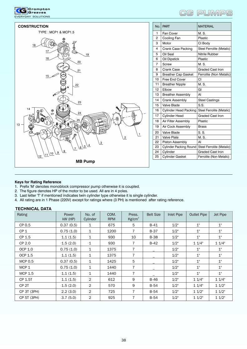
Keys for Rating Reference1. Prefix 'M' denotes monoblock compressor pump otherwise it is coupled.2. The figure denotes HP of the motor to be used. All are in 4 poles.3. Last letter 'T' if mentioned indicates twin cylinder type otherwise it is single cylinder.4. All rating are in 1 Phase (220V) except for ratings where (3 PH) is mentioned after rating reference.
MB Pump
18
TYPE : MCP1 & MCP1.5
17
16
19
20
21
22
23
15
24
25
14
13
1211
10 9 87 6 5 4
3
21
No.
2
1
Cooling Fan
Fan Cover
PART
4
3
Oil Seal
Oil Dipstick
Motor
Crank Case Packing
5
7
Crank Case8
Breather Cap Gasket9
Free End Cover10
Breather Nipple11
Elbow12
13
Crank Assembly14
Valve Blade15
Cylinder Head Packing16
Cylinder Head17
Air Filter Assembly18
Air Cock Assembly19
Valve Blade20
Valve Plate21
Piston Assembly22
Cylinder Packing Round23
Cylinder24
25 Cylinder Gasket
MATERIAL
Plastic
M. S.
Screw
6 Plastic
M. S.
AI
Steel Ferrolite (Metalic)
CI
GI
Steel Castings
S.S.
Plastic
S. S.
CI Body
Nitrile Rubber
Ferrolite (Non Metalic)
M. S.
Steel Ferrolite (Metalic)
Brass
M. S.
AI
Steel Ferrolite (Metalic)
Graded Cast Iron
Graded Cast Iron
Graded Cast Iron
Breather Assembly
Ferrolite (Non Metalic)
CONSTRUCTION
TECHNICAL DATA
Rating Power No. of COM. Press. Belt Size Inlet Pipe Outlet Pipe Jet Pipe2kW (HP) Cylinder RPM Kg/cm
CP 0.5 0.37 (0.5) 1 675 5 B-41 1/2" 1" 1"
CP 1 0.75 (1.0) 1 1200 7 B-37 1/2" 1" 1"
CP 1.5 1.1 (1.5) 1 930 10 B-38 1/2" 1" 1"
CP 2.0 1.5 (2.0) 1 930 7 B-42 1/2" 1 1/4" 1 1/4"
OCP 1.0 0.75 (1.0) 1 1375 7 _ 1/2" 1" 1"
OCP 1.5 1.1 (1.5) 1 1375 7 _ 1/2" 1" 1"
MCP 0.5 0.37 (0.5) 1 1425 5 _ 1/2" 1" 1"
MCP 1 0.75 (1.0) 1 1440 7 _ 1/2" 1" 1"
MCP 1.5 1.1 (1.5) 1 1440 7 _ 1/2" 1" 1"
CP 1.5T 1.1 (1.5) 2 612 9 B-46 1/2" 1 1/4" 1 1/4"
CP 2T 1.5 (2.0) 2 570 9 B-54 1/2" 1 1/4" 1 1/2"
CP 3T (3PH) 2.2 (3.0) 2 725 7 B-54 1/2" 1 1/2" 1 1/2"
CP 5T (3PH) 3.7 (5.0) 2 925 7 B-54 1/2" 1 1/2" 1 1/2"
CG PUMPSCG PUMPS
38

PERFORMANCE CHART
Rating Motor Pumping Lifting kW (HP) Height * Height ** 30 45 60 90 120
Discharge in LPH
CP 0.5 0.37 (0.5) 25% 75% 750 675 575
50% 50% 900 750 650
75% 25% 2000 1500 1375
CP 1 0.75 (1.0) 25% 75% 1500 1350 1150 1000 900
50% 50% 1800 1500 1300 1100 1000
75% 25% 4000 3000 2750 2500 2400
CP 1.5 1.1 (1.5) 25% 75% 1700 1550 1300 1100 1000
50% 50% 2100 1700 1450 1200 1100
75% 25% 4150 3100 2900 2600 2500
CP 2.0 1.5 (2.0) 25% 75% 1900 1725 1500 1300 1175
50% 50% 2300 1900 1700 1425 1350
75% 25% 4400 3350 3125 2850 2700
OCP 1.0 0.75 (1.0) 25% 75% 1550 1400 1200 1050 950
50% 50% 1850 1550 1350 1150 1050
75% 25% 4050 3050 2800 2550 2450
OCP 1.5 1.1 (1.5) 25% 75% 1750 1600 1350 1150 1050
50% 50% 2150 1750 1500 1250 1150
75% 25% 4200 3150 2950 2650 2550
MCP 0.5 0.37 (0.5) 25% 75% 775 700
50% 50% 925 775
75% 25% 2025 1525
MCP 1 0.75 (1.0) 25% 75% 1550 1400 1200 1050 950
50% 50% 1850 1550 1350 1150 1050
75% 25% 4050 3050 2800 2550 2450
MCP 1.5 1.1 (1.5) 25% 75% 1750 1600 1350 1150 1050
50% 50% 2150 1750 1500 1250 1150
75% 25% 4200 3150 2950 2650 2550
CP 1.5T / CP 1.5TM 1.1 (1.5) 25% 75% 1800 1650 1400 1200 1050
50% 50% 2200 1800 1550 1300 1150
75% 25% 4250 3200 3000 2650 2550
CP 2T / CP 2TM 1.5 (2.0) 25% 75% 3200 2900 2600 2050 1850
50% 50% 3800 3200 3000 2300 2100
75% 25% 8200 6200 5700 5200 4900
CP 3T (3PH) 2.2 (3.0) 25% 75% 4500 4100 3600 3100 2600
50% 50% 5400 4500 3900 3300 3000
75% 25% 12000 9000 8500 8000 7600
CP 5T (3PH) 3.7 (5.0) 25% 75% 7500 7000 6000 5000 4500
50% 50% 9000 7500 6500 5500 5000
75% 25% 20000 15000 14500 13750 13500
Depth in Metres
* Pumping Height is the vertical distance between water level and the centre of the air distributor.
** Lifting Height is the vertical distance between water level and centre of water outlet pipe.
Note : Discharge is only indicative. Actual discharge depends on availability of water in borewell based on strength of water source, submersion of jet, air leakage through pipes etc. and ratio of pumping height to lifting height.
Keys for Rating Reference
1. Prefix 'M' denotes monoblock compressor pump otherwise it is coupled.
2. The figure denotes HP of the motor to be used. All are in 4 poles.
3. Last letter 'T' if mentioned indicates twin cylinder type otherwise it is single cylinder.
4. All rating are in 1 Phase (220V) except for ratings where (3 PH) is mentioned after rating reference.
5. Prefix 'O' denotes Oil free Compressor Pump
CG PUMPSCG PUMPS
39

DIMENSIONS & SHIPPING SPECIFICATIONS
H
L W VIEW 'X'
'X'
BCE
F D
A B C D E F L W H
NetWeight
Kg.
GrossWeight
Kg.
VolumeCu. M.
CP 1.5T/ CP 1.5TM 700 600 50 230 190 17 810 410 480 49.7 72 0.277
CP 2T/ CP 2TM 700 600 50 230 190 17 810 410 480 49.7 72 0.277
CP 3T(3 PH) 875 580 147.5 300 250 17 1080 460 626 84 118 0.438
CP 5T (3PH) 875 580 147.5 300 250 17 1080 460 626 84 118 0.438
Rating
Dimensions (mm) Shipping Specifications
A B C D E F L W H
NetWeight
Kg.
GrossWeight
Kg.
VolumeCu. M.
CP 1.0 203 160 15 142 112 21.5 620 320 480 53.60 84.50 0.267
CP 1.5
CP 2.0
203 160 15 142 112 21.5 620 320 480 58.20 93.25 0.267
OCP 1.0 560 450 55 270 240 15.0 700 420 500 55.00 80.00 0.193
OCP 1.5 560 450 55 270 240 15.0 700 420 500 57.00 82.00 0.193
Rating
Dimensions (mm) Shipping Specifications
CP 0.5 203 160 15 142 112 21.5 620 320 480 53.60 84.50 0.267
390 330 30 230 190 20.0 540 340 500 77.80 100.80 0.198
A
B
BF
D
VIEW 'X'
LH
C
W
'X'
DIMENSIONS & SHIPPING SPECIFICATIONS
CG PUMPSCG PUMPS
40
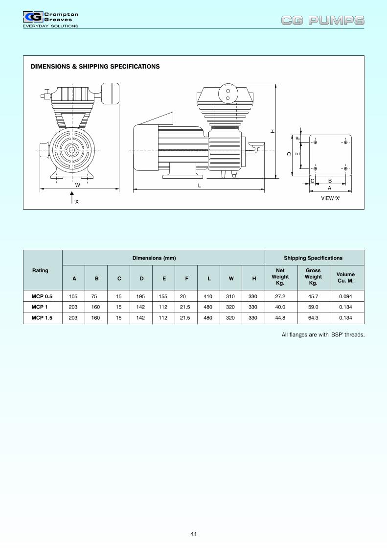
DIMENSIONS & SHIPPING SPECIFICATIONS
F
L
H
D E
A
BCW
VIEW 'X''X'
A B C D E F L W H
NetWeight
Kg.
GrossWeight
Kg.
VolumeCu. M.
MCP 0.5 105 75 15 195 155 20 410 310 330 27.2 45.7 0.094
MCP 1 203 160 15 142 112 21.5 480 320 330 40.0 59.0 0.134
MCP 1.5 203 160 15 142 112 21.5 480 320 330 44.8 64.3 0.134
Rating
Dimensions (mm) Shipping Specifications
CG PUMPSCG PUMPS
All flanges are with 'BSP' threads.
41
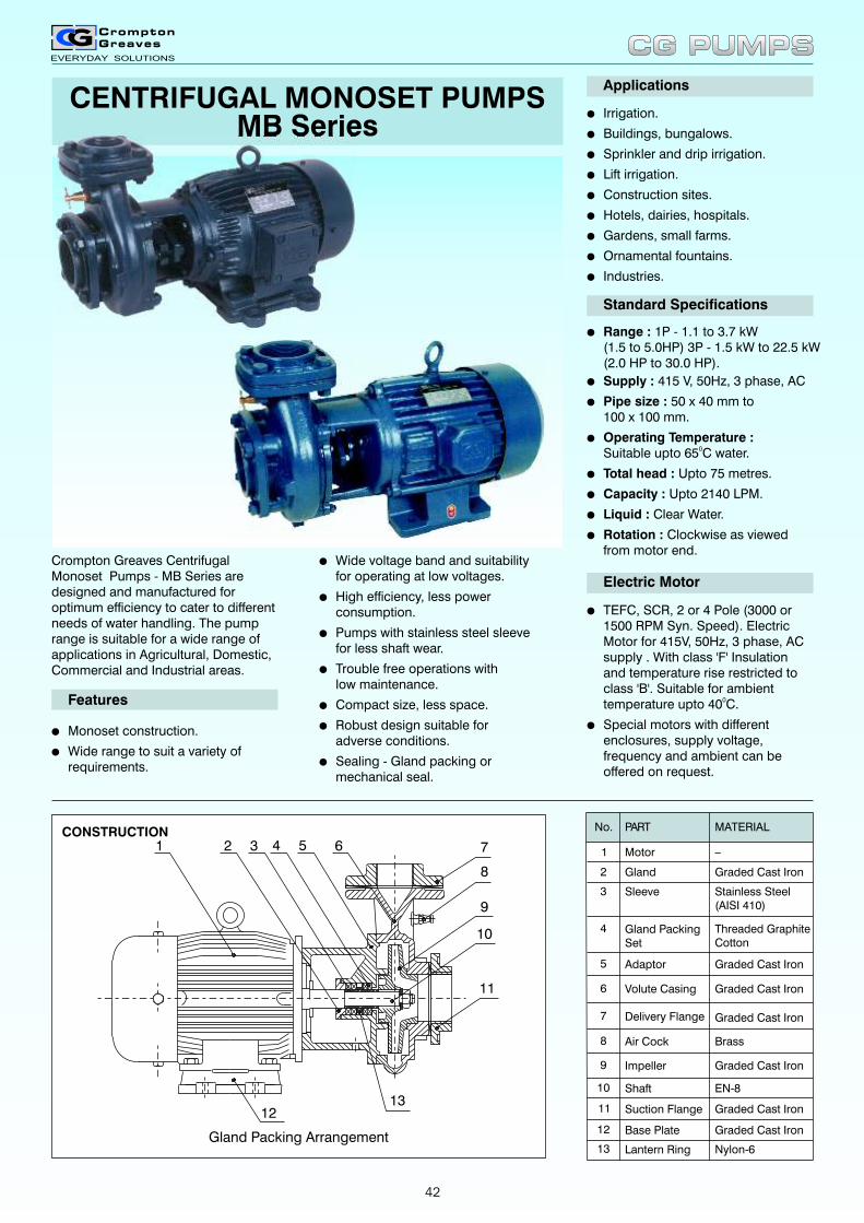
CENTRIFUGAL MONOSET PUMPSMB Series
l
l
l
l
l
l
l
l
l
Irrigation.
Buildings, bungalows.
Sprinkler and drip irrigation.
Lift irrigation.
Construction sites.
Hotels, dairies, hospitals.
Gardens, small farms.
Ornamental fountains.
Industries.
Applications
Standard Specifications
l
l
l
l
l
l
l
l
Range : 1P - 1.1 to 3.7 kW(1.5 to 5.0HP) 3P - 1.5 kW to 22.5 kW(2.0 HP to 30.0 HP).
Supply : 415 V, 50Hz, 3 phase, AC
Pipe size : 50 x 40 mm to100 x 100 mm.
Operating Temperature :0Suitable upto 65 C water.
Total head : Upto 75 metres.
Capacity : Upto 2140 LPM.
Liquid : Clear Water.
Rotation : Clockwise as viewedfrom motor end.
Electric Motor
l
l
TEFC, SCR, 2 or 4 Pole (3000 or 1500 RPM Syn. Speed). Electric Motor for 415V, 50Hz, 3 phase, AC supply . With class 'F' Insulation and temperature rise restricted to class 'B'. Suitable for ambient temperature upto 40 C.0
Special motors with different enclosures, supply voltage, frequency and ambient can be offered on request.
CONSTRUCTION
Crompton Greaves Centrifugal Monoset Pumps - MB Series are designed and manufactured for optimum efficiency to cater to different needs of water handling. The pump range is suitable for a wide range of applications in Agricultural, Domestic, Commercial and Industrial areas.
l
l
Monoset construction.
Wide range to suit a variety ofrequirements.
Features
l
l
l
l
l
l
l
Wide voltage band and suitabilityfor operating at low voltages.
High efficiency, less powerconsumption.
Pumps with stainless steel sleevefor less shaft wear.
Trouble free operations withlow maintenance.
Compact size, less space.
Robust design suitable foradverse conditions.
Sealing - Gland packing ormechanical seal.
No.
2
1
Gland
Motor
PART MATERIAL
_
4
3
Adaptor
Delivery Flange
Volute Casing
Sleeve
Gland PackingSet
Stainless Steel(AISI 410)
Graded Cast Iron
Threaded GraphiteCotton
Graded Cast Iron
Graded Cast Iron
Graded Cast Iron5
6
7
Air Cock Brass8
Impeller Graded Cast Iron9
Shaft EN-810
Suction Flange Graded Cast Iron11
Base Plate Graded Cast Iron12
Lantern Ring Nylon-613Gland Packing Arrangement
7
8
9
1 2 4 5 6
12
11
3
10
13
CG PUMPSCG PUMPS
42
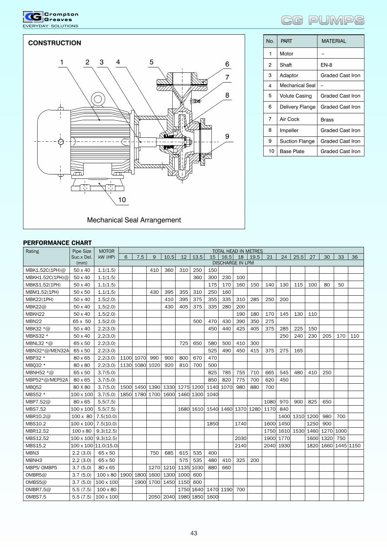
No.
2
1
Shaft
Motor
PART MATERIAL
_
4
3
Volute Casing
Air Cock
Delivery Flange
Adaptor
Mechanical Seal
Graded Cast Iron
EN-8
_
Graded Cast Iron
Brass
Graded Cast Iron5
6
7
Impeller Graded Cast Iron8
Suction Flange Graded Cast Iron9
Base Plate Graded Cast Iron10
Mechanical Seal Arrangement
1
10
5432
9
8
7
6
CONSTRUCTION
Rating Pipe SizeSuc.x Del. kW (HP) 6 7.5 9 10.5 12 13.5 15 16.5 18 19.5 21 24 25.5 27 30 33 36
(mm) DISCHARGE IN LPM
MBK1.52C(1PH)@ 50 x 40 1.1(1.5) 410 360 310 250 150
MBKH1.52C(1PH)@ 50 x 40 1.1(1.5) 360 300 230 100
MBKS1.52(1PH) 50 x 40 1.1(1.5) 175 170 160 150 140 130 115 100 80 50
MBM1.52(1PH) 50 x 50 1.1(1.5) 430 395 355 310 250 160
MBK22(1PH) 50 x 40 1.5(2.0) 410 395 375 355 335 310 285 250 200
MBK22@ 50 x 40 1.5(2.0) 430 405 375 335 280 200
MBKH22 50 x 40 1.5(2.0) 190 180 170 145 130 110
MBN22 65 x 50 1.5(2.0) 500 470 430 390 350 275
MBK32 *@ 50 x 40 2.2(3.0) 450 440 425 405 375 285 225 150
MBKS32 * 50 x 40 2.2(3.0) 250 240 230 205 170 110
MBNL32 *@ 65 x 50 2.2(3.0) 725 650 580 500 410 300
MBN32*@/MEN32A 65 x 50 2.2(3.0) 525 490 450 415 375 275 165
MBP32 * 80 x 65 2.2(3.0) 1100 1070 990 900 800 670 470
MBQ32 * 80 x 80 2.2(3.0) 1130 1080 1020 920 810 700 500
MBNH52 *@ 65 x 50 3.7(5.0) 825 785 755 710 665 545 480 410 250
MBP52*@/MEP52A 80 x 65 3.7(5.0) 850 820 775 700 620 450
MBQ52 80 X 80 3.7(5.0) 1500 1450 1390 1330 1275 1200 1140 1070 980 880 700
MBS52 * 100 x 100 3.7(5.0) 1850 1780 1700 1600 1460 1300 1040
MBP7.52@ 80 x 65 5.5(7.5) 1080 970 900 825 650
MBS7.52 100 x 100 5.5(7.5) 1680 1610 1540 1460 1370 1280 1170 840
MBR10.2@ 100 x 80 7.5(10.0) 1400 1310 1200 980 700
MBS10.2 100 x 100 7.5(10.0) 1850 1740 1600 1450 1250 900
MBR12.52 100 x 80 9.3(12.5) 1750 1610 1530 1460 1270 1000
MBS12.52 100 x 100 9.3(12.5) 2030 1900 1770 1600 1320 750
MBS15.2 100 x 100 11.0(15.0) 2140 2040 1930 1820 1660 1445 1150
MBN3 2.2 (3.0) 65 x 50 750 685 615 535 400
MBNH3 2.2 (3.0) 65 x 50 575 535 480 410 325 200
MBP5/ OMBP5 3.7 (5.0) 80 x 65 1270 1210 1135 1030 880 660
OMBR5@ 3.7 (5.0) 100 x 80 1900 1800 1600 1300 1000 600
OMBS5@ 3.7 (5.0) 100 x 100 1900 1700 1450 1150 600
OMBR7.5@ 5.5 (7.5) 100 x 80 1750 1640 1470 1190 700
OMBS7.5 5.5 (7.5) 100 x 100 2050 2040 1980 1850 1600
MOTOR TOTAL HEAD IN METRES
PERFORMANCE CHART
CG PUMPSCG PUMPS
43
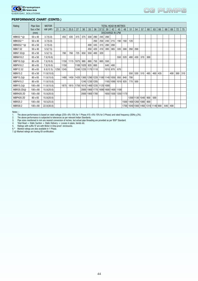
Rating Pipe Size MOTOR TOTAL HEAD IN METRES
Suc.x Del. kW (HP) 21 24 25.5 27 30 33 36 37.5 39 42 45 48 51 54 57 60 63 66 68 69 72 75
(mm) DISCHARGE IN LPM
MBK52 *@ 50 x 40 3.7(5.0) 455 435 415 375 330 280 245 200
MBKS52 * 50 x 40 3.7(5.0) 260 250 240 215 190 160 120
MBNS52 *@ 65 x 50 3.7(5.0) 400 345 315 280 200
MBK7.52 50 x 40 5.5(7.5) 450 420 410 395 365 335 300 260 200
MBN7.52@ 65 x 50 5.5(7.5) 780 760 725 650 550 400 320
MBNH10.2 65 x 50 7.5(10.0) 550 520 480 430 370 300
MBP10.2@ 80 x 65 7.5(10.0) 1150 1115 1075 980 880 750 665 550
MBPH10.2 80 x 65 7.5(10.0) 1150 1100 1020 920 800 640 400
MBP12.52 80 x 65 9.3(12.5) 1250 1245 1240 1220 1170 1110 1010 870 670
MBN15.2 65 x 50 11.0(15.0) 550 530 510 485 460 435 400 360 310
MBP15.2@ 80 x 65 11.0(15.0) 1480 1450 1420 1360 1290 1220 1180 1140 1050 950 840 700
MBPH15.2 80 x 65 11.0(15.0) 1240 1230 1205 1165 1090 1010 920 770 500
MBR15.2@ 100 x 80 11.0(15.0) 1875 1815 1750 1615 1460 1235 1125 1000
MBR20.2D@ 100 x 80 15.0(20.0) 2000 1900 1770 1690 1600 1400 1100
MBRH20.2D 100 x 80 15.0(20.0) 2000 1900 1780 1650 1500 1350 1170
MBPH20.2D 80 x 65 15.0(20.0) 1200 1130 1040 900 500
MBR25.2 100 x 80 18.5(25.0) 1500 1400 1260 1080 800
MBR30.2 100 x 80 22.0(30.0) 1700 1640 1560 1460 1310 1140 900 640 400
PERFORMANCE CHART (CONTD.)
Notes :- 1. The above performance is based on 2. The above performance is subjected to tolerances as per relevant Indian Standards.3. Pipe sizes mentioned in mm are nearest conversion of inches, but actual pipe threading are provided as per 'BSP' Standard.4. Total Head = Static Suction + Static Delivery + Losses in pipes, bends etc.5. Ratings with suffix 'D' are with Motor in Drip-proof enclosures.6.* Marked ratings are also available in 1 Phase.7.@ Marked ratings are having ISI certification.
rated voltage (220+6%-15% for 1 Phase 415+6%-15% for 3 Phase) and rated frequency (50Hz+3%).
CG PUMPSCG PUMPS
44
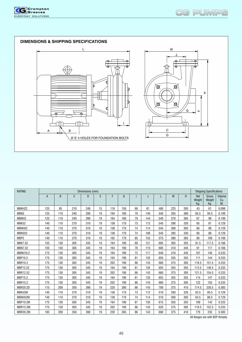
RATING Dimensions (mm) Shipping Specifications
A B C D E F G I J L W H Net Gross VolumeWeight Weight Cu.
Kg. Kg. M.
MBKH22 125 85 210 246 15 116 150 66 81 480 225 265 43 61 0.098
MBN3 125 110 240 280 19 164 160 79 140 540 355 380 65.5 94.5 0.199
MBNH3 125 110 240 280 19 164 160 79 144 540 370 365 67 96 0.199
MBK52 140 110 270 310 19 138 170 73 112 545 290 320 65 87 0.129
MBNH52 140 110 270 310 19 138 170 74 114 545 300 305 66 88 0.129
MBNS52 140 110 270 310 19 138 170 74 106 545 285 330 66 88 0.129
MBP5 140 110 270 310 19 162 170 85 153 575 380 365 80 109 0.199
MBK7.52 155 130 305 345 19 164 190 69 121 605 305 355 91.5 117.5 0.166
MBN7.52 155 130 305 345 19 164 190 76 115 605 310 345 91 117 0.166
MBNH10.2 175 130 305 345 19 164 190 72 117 640 310 345 107 140 0.233
MBP10.2 175 130 305 345 19 164 190 81 135 655 355 355 111 144 0.233
MBR10.2 175 130 305 345 19 202 190 86 143 660 375 395 118.5 151.5 0.233
MBP12.52 175 130 305 345 19 164 190 81 135 655 355 355 113.5 146.5 0.233
MBR12.52 175 130 305 345 19 202 190 86 143 660 375 395 121.5 154.5 0.233
MBP15.2 175 130 305 345 19 164 190 81 135 655 355 355 114 147 0.233
MBR15.2 175 130 305 345 19 202 190 86 143 660 375 395 122 155 0.233
MBR20.2D 115 200 350 390 19 220 300 86 143 700 375 410 174.5 230.5 0.383
MBK52M 140 110 270 310 19 138 170 73 112 510 290 320 63.5 85.5 0.129
MBNH52M 140 110 270 310 19 138 170 74 114 510 300 305 64.5 86.5 0.129
MBP10.2M 175 130 305 345 19 164 190 81 135 615 355 355 109 142 0.233
MBR15.2M 175 130 305 345 19 202 190 86 143 620 375 395 119.5 152.5 0.233
MBR20.2M 185 200 350 390 19 220 265 86 143 690 375 410 179 235 0.383
All flanges are with BSP threads.
A B
L W
F
D
C
Ø 'E' 4 HOLES FOR FOUNDATION BOLTS
H
G
I
J
CG PUMPSCG PUMPS
DIMENSIONS & SHIPPING SPECIFICATIONS
45
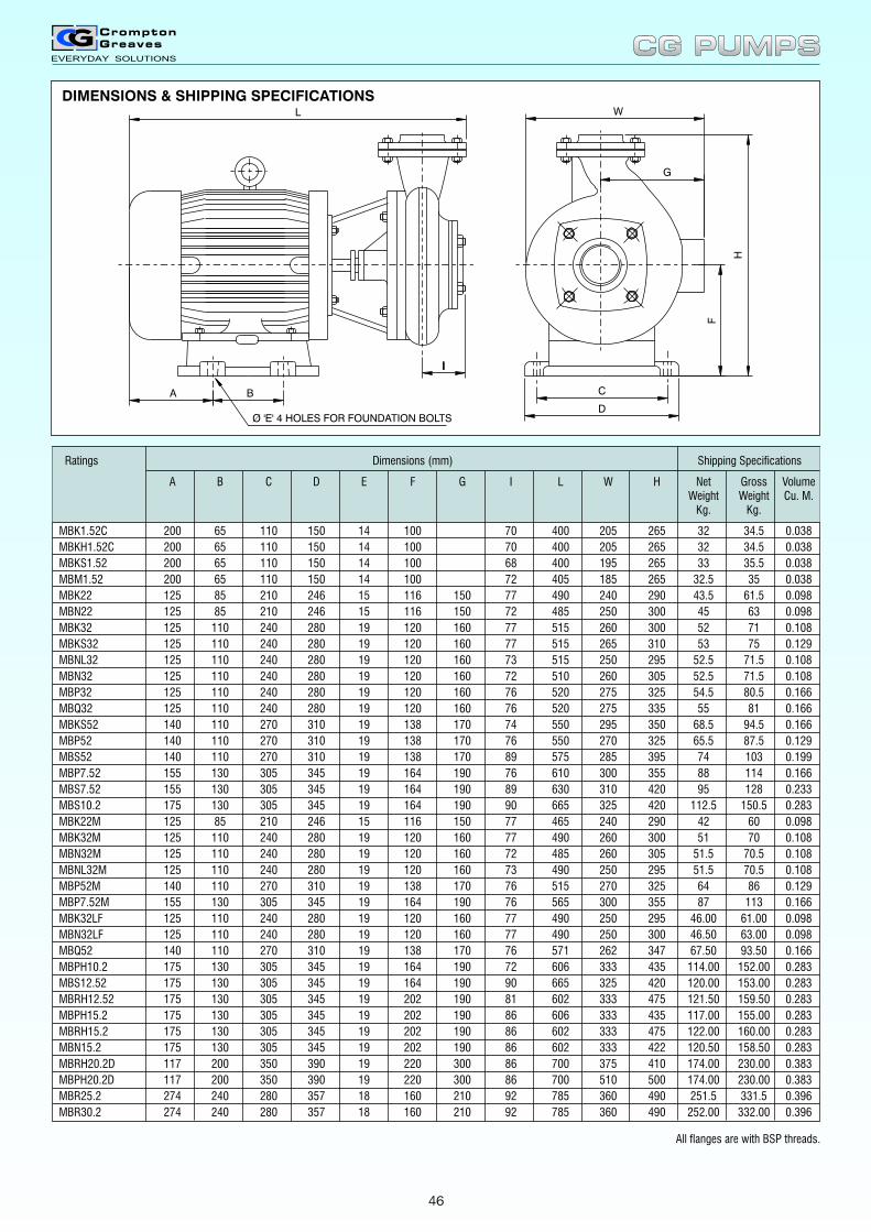
Ratings Dimensions (mm) Shipping Specifications
A B C D E F G I L W H Net Gross VolumeWeight Weight Cu. M.
Kg. Kg.
MBK1.52C 200 65 110 150 14 100 70 400 205 265 32 34.5 0.038
MBKH1.52C 200 65 110 150 14 100 70 400 205 265 32 34.5 0.038
MBKS1.52 200 65 110 150 14 100 68 400 195 265 33 35.5 0.038
MBM1.52 200 65 110 150 14 100 72 405 185 265 32.5 35 0.038
MBK22 125 85 210 246 15 116 150 77 490 240 290 43.5 61.5 0.098
MBN22 125 85 210 246 15 116 150 72 485 250 300 45 63 0.098
MBK32 125 110 240 280 19 120 160 77 515 260 300 52 71 0.108
MBKS32 125 110 240 280 19 120 160 77 515 265 310 53 75 0.129
MBNL32 125 110 240 280 19 120 160 73 515 250 295 52.5 71.5 0.108
MBN32 125 110 240 280 19 120 160 72 510 260 305 52.5 71.5 0.108
MBP32 125 110 240 280 19 120 160 76 520 275 325 54.5 80.5 0.166
MBQ32 125 110 240 280 19 120 160 76 520 275 335 55 81 0.166
MBKS52 140 110 270 310 19 138 170 74 550 295 350 68.5 94.5 0.166
MBP52 140 110 270 310 19 138 170 76 550 270 325 65.5 87.5 0.129
MBS52 140 110 270 310 19 138 170 89 575 285 395 74 103 0.199
MBP7.52 155 130 305 345 19 164 190 76 610 300 355 88 114 0.166
MBS7.52 155 130 305 345 19 164 190 89 630 310 420 95 128 0.233
MBS10.2 175 130 305 345 19 164 190 90 665 325 420 112.5 150.5 0.283
MBK22M 125 85 210 246 15 116 150 77 465 240 290 42 60 0.098
MBK32M 125 110 240 280 19 120 160 77 490 260 300 51 70 0.108
MBN32M 125 110 240 280 19 120 160 72 485 260 305 51.5 70.5 0.108
MBNL32M 125 110 240 280 19 120 160 73 490 250 295 51.5 70.5 0.108
MBP52M 140 110 270 310 19 138 170 76 515 270 325 64 86 0.129
MBP7.52M 155 130 305 345 19 164 190 76 565 300 355 87 113 0.166
MBK32LF 125 110 240 280 19 120 160 77 490 250 295 46.00 61.00 0.098
MBN32LF 125 110 240 280 19 120 160 77 490 250 300 46.50 63.00 0.098
MBQ52 140 110 270 310 19 138 170 76 571 262 347 67.50 93.50 0.166
MBPH10.2 175 130 305 345 19 164 190 72 606 333 435 114.00 152.00 0.283
MBS12.52 175 130 305 345 19 164 190 90 665 325 420 120.00 153.00 0.283
MBRH12.52 175 130 305 345 19 202 190 81 602 333 475 121.50 159.50 0.283
MBPH15.2 175 130 305 345 19 202 190 86 606 333 435 117.00 155.00 0.283
MBRH15.2 175 130 305 345 19 202 190 86 602 333 475 122.00 160.00 0.283
MBN15.2 175 130 305 345 19 202 190 86 602 333 422 120.50 158.50 0.283
MBRH20.2D 117 200 350 390 19 220 300 86 700 375 410 174.00 230.00 0.383
MBPH20.2D 117 200 350 390 19 220 300 86 700 510 500 174.00 230.00 0.383
MBR25.2 274 240 280 357 18 160 210 92 785 360 490 251.5 331.5 0.396
MBR30.2 274 240 280 357 18 160 210 92 785 360 490 252.00 332.00 0.396
DIMENSIONS & SHIPPING SPECIFICATIONS
II
Ø
A B
L
G
W
F
D
C
H
'E' 4 HOLES FOR FOUNDATION BOLTS
CG PUMPSCG PUMPS
All flanges are with BSP threads.
46
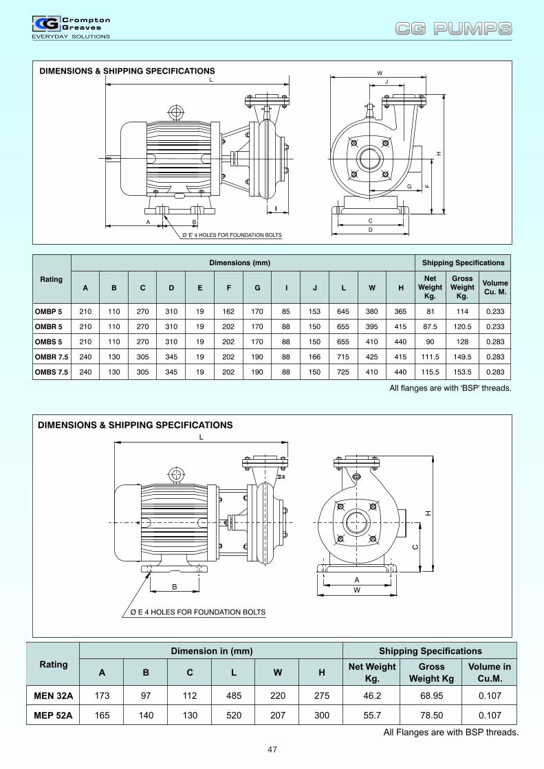
DIMENSIONS & SHIPPING SPECIFICATIONS
F
D
C
H
J
W
G
A B
L
II
Ø 'E' 4 HOLES FOR FOUNDATION BOLTS
All flanges are with 'BSP' threads.
A B C D E F G I J L W H
NetWeight
Kg.
VolumeCu. M.
OMBP 5 210 110 270 310 19 162 170 85 153 645 380 365 81 114 0.233
OMBR 5 210 110 270 310 19 202 170 88 150 655 395 415 87.5 120.5 0.233
OMBS 5 210 110 270 310 19 202 170 88 150 655 410 440 90 128 0.283
OMBR 7.5 240 130 305 345 19 202 190 88 166 715 425 415 111.5 149.5 0.283
OMBS 7.5 240 130 305 345 19 202 190 88 150 725 410 440 115.5 153.5 0.283
Rating
Dimensions (mm) Shipping Specifications
GrossWeight
Kg.
W
A
L
B
C
H
Ø E 4 HOLES FOR FOUNDATION BOLTS
A B C L W HNet Weight
Kg.
Gross
Weight Kg
Volume in
Cu.M.
MEN 32A 173 97 112 485 220 275 46.2 68.95 0.107
MEP 52A 165 140 130 520 207 300 55.7 78.50 0.107
All Flanges are with BSP threads.
Shipping SpecificationsDimension in (mm)
Rating
CG PUMPSCG PUMPS
DIMENSIONS & SHIPPING SPECIFICATIONS
47
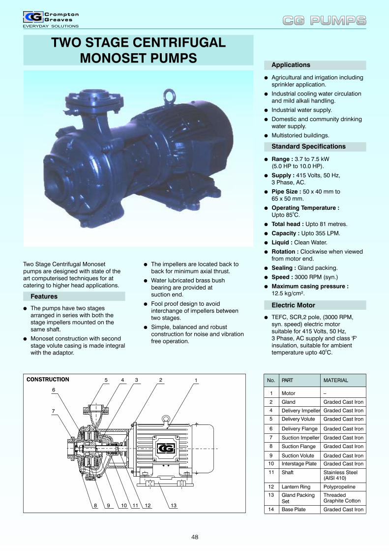
TWO STAGE CENTRIFUGALMONOSET PUMPS
lThe impellers are located back to back for minimum axial thrust.
lWater lubricated brass bush bearing are provided atsuction end.
lFool proof design to avoidinterchange of impellers betweentwo stages.
lSimple, balanced and robust construction for noise and vibration free operation.
lAgricultural and irrigation including sprinkler application.
lIndustrial cooling water circulation and mild alkali handling.
lIndustrial water supply.
lDomestic and community drinking water supply.
lMultistoried buildings.
Applications
Standard Specifications
lRange : 3.7 to 7.5 kW(5.0 HP to 10.0 HP).
lSupply : 415 Volts, 50 Hz,3 Phase, AC.
lPipe Size : 50 x 40 mm to65 x 50 mm.
lOperating Temperature :0Upto 85 C.
lTotal head : Upto 81 metres.
lCapacity : Upto 355 LPM.
lLiquid : Clean Water.
lRotation : Clockwise when viewed from motor end.
lSealing : Gland packing.
lSpeed : 3000 RPM (syn.)
lMaximum casing pressure :12.5 kg/cm².
Electric Motor
lTEFC, SCR,2 pole, (3000 RPM, syn. speed) electric motor suitable for 415 Volts, 50 Hz,3 Phase, AC supply and class 'F' insulation, suitable for ambient temperature upto 40 C.0
Two Stage Centrifugal Monoset pumps are designed with state of the art computerised techniques for at catering to higher head applications.
lThe pumps have two stages arranged in series with both the stage impellers mounted on the same shaft.
lMonoset construction with second stage volute casing is made integralwith the adaptor.
Features
CONSTRUCTION No.
2
1
Gland
Motor
PART MATERIAL
_
4
Delivery Volute
Suction Impeller
Delivery Flange
Delivery Impeller
Graded Cast Iron
Graded Cast Iron
Graded Cast Iron
Graded Cast Iron
Graded Cast Iron5
6
7
Suction Flange Graded Cast Iron8
Suction Volute Graded Cast Iron9
Interstage Plate Graded Cast Iron10
Shaft Stainless Steel(AISI 410)
11
Lantern Ring Polypropeline12
Gland PackingSet
ThreadedGraphite Cotton
13
Base Plate Graded Cast Iron14
145
6
7
131298
3
10
2
11
CG PUMPSCG PUMPS
48
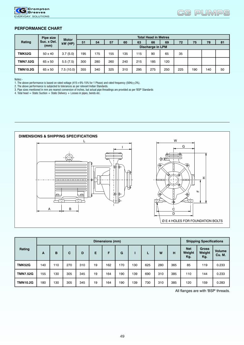
PERFORMANCE CHART
51 54 57 60 63 66 69 72 75 78 81
TMK52G 195 175 155 135 115 90 65 35
TMN7.52G 300 280 260 240 215 185 120
TMN10.2G 355 340 325 310 295 275 250 225 190 140 50
Total Head in Metres
Discharge in LPM
Rating
3.7 (5.0)
5.5 (7.5)
7.5 (10.0)
Motor kW (HP)
50 x 40
65 x 50
65 x 50
Pipe sizeSuc. x Del.
(mm)
All flanges are with 'BSP' threads.
A B C D E F G I L W H
NetWeight
Kg.
GrossWeight
Kg.
VolumeCu. M.
TMK52G 140 110 270 310 19 162 170 130 625 280 365 85 119 0.233
TMN7.52G 155 130 305 345 19 164 190 139 690 310 385 110 144 0.233
TMN10.2G 180 130 305 345 19 164 190 139 730 310 385 120 159 0.283
Rating
Dimensions (mm) Shipping Specifications
I
L
A B
D
C
H
F
G
W
Ø E 4 HOLES FOR FOUNDATION BOLTS
CG PUMPSCG PUMPS
DIMENSIONS & SHIPPING SPECIFICATIONS
Notes:-1. The above performance is based on rated voltage (415+6%-15% for 1 Phase) and rated frequency (50Hz+3%).2. The above performance is subjected to tolerances as per relevant Indian Standards.3. Pipe sizes mentioned in mm are nearest conversion of inches, but actual pipe threadings are provided as per 'BSP' Standards4. Total head = Static Suction + Static Delivery + Losses in pipes, bends etc.
49
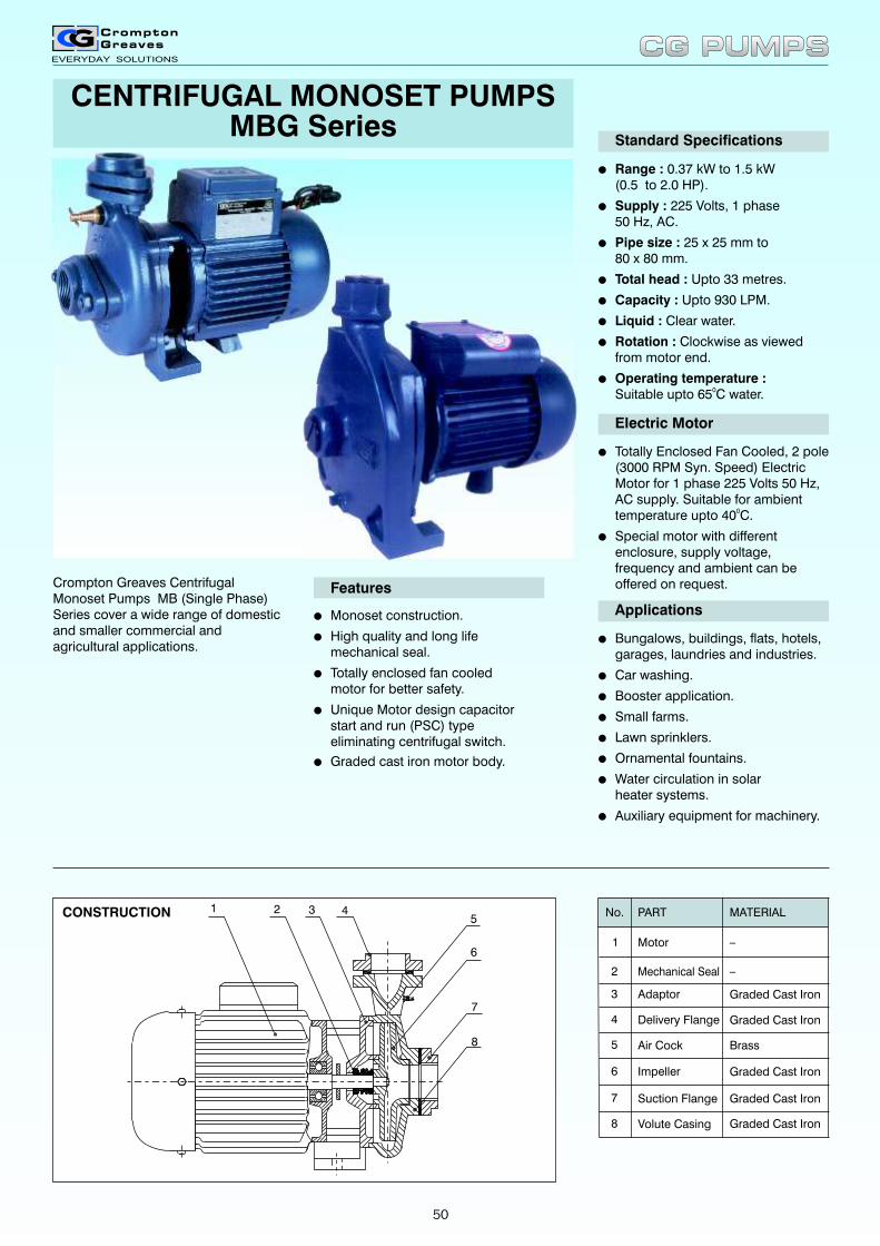
CENTRIFUGAL MONOSET PUMPS MBG Series
Crompton Greaves Centrifugal Monoset Pumps MB (Single Phase) Series cover a wide range of domestic and smaller commercial and agricultural applications.
Standard Specifications
l
l
l
l
l
l
l
l
Range : 0.37 kW to 1.5 kW(0.5 to 2.0 HP).
Supply : 225 Volts, 1 phase50 Hz, AC.
Pipe size : 25 x 25 mm to80 x 80 mm.
Total head : Upto 33 metres.
Capacity : Upto 930 LPM.
Liquid : Clear water.
Rotation : Clockwise as viewed from motor end.
Operating temperature :0Suitable upto 65 C water.
Electric Motor
l
l
Totally Enclosed Fan Cooled, 2 pole (3000 RPM Syn. Speed) Electric Motor for 1 phase 225 Volts 50 Hz, AC supply. Suitable for ambient
0temperature upto 40 C.
Special motor with different enclosure, supply voltage, frequency and ambient can be offered on request.
l
l
l
l
l
l
l
l
Bungalows, buildings, flats, hotels,garages, laundries and industries.
Car washing.
Booster application.
Small farms.
Lawn sprinklers.
Ornamental fountains.
Water circulation in solarheater systems.
Auxiliary equipment for machinery.
Applicationsl
l
l
l
Monoset construction.
High quality and long lifemechanical seal.
Totally enclosed fan cooledmotor for better safety.
Unique Motor design capacitor start and run (PSC) type eliminating centrifugal switch.
Features
lGraded cast iron motor body.
Mechanical Seal
Motor
PART
Air Cock
Suction Flange
Impeller
Adaptor
Delivery Flange
Volute Casing
_
MATERIAL
_
Graded Cast Iron
Graded Cast Iron
Graded Cast Iron
Graded Cast Iron
Brass
Graded Cast Iron
No.
2
1
4
3
5
6
7
8
1 2 3 45
6
7
8
CG PUMPSCG PUMPS
CONSTRUCTION
50
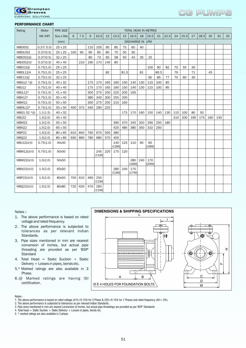
Rating Motor
kW (HP) Suc.x Del. 6 7.5 9 10.5 12 13.5 15 16.5 18 19.5 21 22.5 24 25.5 27 28.5 30 32 33
(mm) DISCHARGE IN LPM
MBD052 0.37( 0.5) 25 x 25 110 105 95 85 75 60 40
MBDL052 0.37(0.5) 25 x 25 100 95 90 85 80 70 50 30
MBE052@ 0.37(0.5) 32 x 25 80 73 65 58 50 43 35 25
MBJ052/LV 0.37(0.5) 40 x 40 210 190 170 140 80
MBD12@ 0.75(1.0) 25 x 25 100 90 82 70 55 30
MBDL12/A 0.75(1.0) 25 x 25 82 81.5 81 80.5 79 71 45
MBE12@ 0.75(1.0) 32 x 25 90 85 77 70 60 30
MBG12 *@ 0.75(1.0) 40 x 32 175 170 165 160 150 140 130 115 100 85
MBJ12 0.75(1.0) 40 x 40 175 170 165 160 150 140 130 115 100 85
MBJL12* 0.75(1.0) 41 x 40 300 275 250 225 200 165
MBK12* 0.75(1.0) 50 x 40 380 340 300 255 200
MBM12 0.75(1.0) 50 x 50 300 275 250 215 160
MBML12* 0.75(1.0) 50 x 50 400 375 340 290 225
MBG1.52 *@ 1.1(1.5) 40 x 32 175 170 160 150 140 130 115 100 80 50
MBJ22 1.5(2.0) 40 x 40 210 200 190 175 160 130
MBM22 1.5(2.0) 50 x 50 390 370 345 320 290 250 180
MBN22 1.5(2.0) 65 x 50 425 480 380 350 310 250
MBP22 1.5(2.0) 80 x 65 910 840 760 670 550 380
MBQ22 1.5(2.0) 80 x 80 930 860 780 680 570 400
MBJ12LV/(I) 0.75(1.0) 40x40 140 125 110 90 60(13M) (19M)
MBM12LV/(I) 0.75(1.0) 50x50 245 220 175 120(11M)
MBM22LV/(I) 1.5(2.0) 50x50 280 240 170(16M) (20M)
MBN22LV/(I) 1.5(2.0) 65x50 280 240 170(13M) (17M)
MBP22LV/(I) 1.5(2.0) 80x50 700 610 460 250(11M)
MBQ22LV/(I) 1.5(2.0) 80x80 720 620 470 260(11M)
PIPE SIZE TOTAL HEAD IN METRES
DIMENSIONS & SHIPPING SPECIFICATIONS
H
W
D
I
Ø E 4 HOLES FOR FOUNDATION BOLTS
CBA
L
F
Notes :-
1. The above performance is based on rated voltage and rated frequency.
2. The above performance is subjected to tolerances as per relevant Indian Standards.
3. Pipe sizes mentioned in mm are nearest conversion of inches, but actual pipe threading are provided as per 'BSP' Standard
4. Total Head = Static Suction + Static Delivery + Losses in pipes, bends etc.
5.* Marked ratings are also available in 3 Phase.
6.@ Marked ratings are having ISI certification.
CG PUMPSCG PUMPS
PERFORMANCE CHART
Notes:-1. The above performance is based on 2. The above performance is subjected to tolerances as per relevant Indian Standards.3. Pipe sizes mentioned in mm are nearest conversion of inches, but actual pipe threadings are provided as per 'BSP' Standards4. Total head = Static Suction + Static Delivery + Losses in pipes, bends etc.5. * marked ratings are also available in 3 phase.
rated voltage (415+6-15% for 3 Phase & 220+6-15% for 1 Phase) and rated frequency (50+-3%).
51
DIMENSIONS & SHIPPING SPECIFICATIONS
A C D E F I L W H
NetWeight
Kg.
Volume Cu.M.
220 115 150 14 100 59 340 180 250 25 27.5 0.028 MBD12
MBE12
MBG12
MBJ12/LV/(I)
MBJL12
MBM12/LV/(I)
MBML12
MBK12
Dimensions (mm) Shipping Specifications
Rating
220
220
220
220
220
220
220
115
115
115
115
115
115
115
150
150
150
150
150
150
150
14
14
14
14
14
14
14
100
100
100
100
100
100
100
71
67
67
67
70
70
70
350
345
345
345
355
355
355
185
170
170
170
170
175
175
250
255
255
255
280
270
270
25
24.5
24.5
24.5
26.5
26.5
26.5
27.5
27
27
27
27
29
29
0.028
0.028
0.028
0.028
0.028
0.028
0.028
GrossWeight
Kg.
L
I
A C
D
F
H
Ø E 2 HOLES FOR FOUNDATION BOLTS
W
All flanges are with 'BSP' threads.
CG PUMPSCG PUMPS
A B C D E F I L W H
Net Weight
Kg.
Gross Weight
Kg.
Volume Cu.M.
MBD052 160 45 110 140 12 90 61 315 160 225 15.1 16.8 0.021
MBDL052 165 45 115 145 12 95 55 305 155 225 13.6 15.3 0.021
Rating
Dimensions (mm) Shipping Specifications
MBE052 175 50 100 140 14 90 69 350 160 235 20.5 22.5 0.021
MBJ052 160 45 110 140 12 90 64 325 160 250 17.5 19.5 0.021
MBG1.52 200 65 110 150 14 100 68 400 195 265 33 35.5 0.038
MBJ22 225 80 135 180 14 120 67 435 190 285 42 60 0.098
MBN22/LV/(I) 225 80 135 180 14 120 72 440 205 305 44 62 0.098
MBP22/LV/(I) 225 80 135 180 14 120 76 455 250 325 46 65.5 0.111
MBQ22/LV/(I) 225 80 135 180 14 120 76 455 250 335 46 65.5 0.111
MBM22/LV/(I) 225 80 135 180 14 120 74 445 225 280 45 63 0.098
All flanges are with 'BSP' threads.
52
OPENWELL SUBMERSIBLEMONOSET PUMPS
Crompton Greaves Openwell Submersible pumpsets are specially designed for its robustness and for its applications under the submerged condition. Years of experience, superior design and better manufacturing techniques have resulted into development of this range of pumpsets, which are efficient and reliable in operation. Strict quality assurance standards during the total process ensures trouble free and reliable operation with minimum maintenance.
lSuitable for operation under submerged condition in water.
lSpecially designed to withstand wide voltage fluctuations in 1 phase as well as 3 phase.
lMotor body made of C.I. sturdiness and long life.
lFitted with sleeves and thrust bearing for longer life.
lProvided with strainer in S.S.
lMotor is water lubricated and fitted with good quality oil seal.
lSuitable for applications where wide water level fluctuations take place in suction side.
lAll internal parts of motor are specially coated with primer to prevent rusting for longer life.
lAll 1 phase pumpsets are suppliedwith 10 metres PVC insulated cableand with Control Panel and all3 phase pumpsets are suppliedwith 5 metres PVC insulated cable.
lAll rotating parts are dynamically balanced for longer bearing life and vibration free smooth and silent operation.
Applications
Used for water supply where there is wide fluctuations in water level in suction tank or water supply source.
lIrrigation
lSmall farms
lBungalows, multistoried buildings
lGardens
lDomestic water supply
lCommunity water supply schemes
Standard Specifications
lRange : 1P - 0.37 to 2.2 kW(0.5 to 3.0HP)0.37 to 22.5 kW(0.5 to 30.0 HP).
lPipe Size : 25 x 25 to100 x 100 mm
lSpeed : 3000 RPM (Syn.)
lTotal Head : Upto 87 Metres
lCapacity : Upto 1830 LPM
lLiquid : Clear water
lRotation : Clockwise when viewedfrom motor end
lMotor : Totally enclosed water filled squirrel cage induction motor suitable for 225V/1 phase and415V/3 phase, 50Hz, AC supply.
Features
CG PUMPSCG PUMPS
53
No. PART MATERIAL
Thrust Bearing
End Cover
Thrust BearingLock Nut
Thrust Pad
'ODE' BushHousing
Fibre
Stainless Steel
15
16
17
18
19 Graded Cast Iron
Graded Cast Iron
Bronze
Base Plate
Oil Seal
20
21_
MS (Fabricated)
CONSTRUCTION
No.
2
1
Flange
Strainer
PART MATERIAL
Stainless Steel
4
3
'DE' BushHousing
Sleeve
Bush
Volute
Impeller
Graded Cast Iron
Graded Cast Iron5
6
7
Graded Cast Iron
Graded Cast Iron
Brass
Brass
2021
1 2 3 4 5 6 7 8 9 10 11 12 13 14
18
16
15
17
19
PERFORMANCE CHART
No. PART MATERIAL
Drain Plug
Grommet Plate
_Supply Cable
Stainless Steel13
12
14
Plastic
Shaft8
Motor Body9
Bush Brass10
Sleeve Brass11
Stainless Steel
Graded Cast Iron
CG PUMPSCG PUMPS
Total Head in Metres
Rating Motor Pipe size kW (HP) Suc x Del 6 9 10.5 12 13.5 15 18 19.5 21 24 25.5 27 28.5 30 33 36 39 42 45 48 51 54
(mm) Discharge in LPM
SMD 052(1Ph)*@ 0.37 (0.5) 25 x 25 150 120 105 85 70 30
SMDH 12(1Ph)*@ 0.75 (1.0) 40 x 25 255 245 230 210 200 190 150 125 95 60
SMG 1.52(1Ph)*@ 1.1 (1.5) 40 x 32 270 245 230 220 185 165 130 85 35
SMK 22 (1Ph)*@ 1.5 (2.0) 50 x 40 315 305 295 285 265 255 245 220 205 185 155 110
SMM22(1PH)@ 1.5(2.0) 50 X 50 475 450 430 405 375 310 250 130
SMKS 32 2.2 (3.0) 50 x 40 355 340 330 315 295 265 240 220 195 75
SMN 32 @ 2.2 (3.0) 65 x 50 740 700 660 630 590 500 450 400 210
SMO 32 @ 2.2 (3.0) 65 x 65 830 800 765 720 580 480 360
SMS 32 2.2 (3.0) 100 x 100 1180 950 850 675 300
SMKS 52 3.7 (5.0) 50 x 40 500 485 470 450 420 370 300 120
SMNH 52 3.7 (5.0) 65 x 50 730 700 670 560 480 400 320 200
SMO 52 @ 3.7 (5.0) 65 x 65 840 820 800 750 720 680 570 510 400 240
SMP 52 @ 3.7 (5.0) 80 x 65 1280 1220 1160 1080 940 850 750 450
SMQ 52 @ 3.7 (5.0) 80 x 80 1425 1350 1260 1170 1100 915 800 700
SMS 52 @ 3.7 (5.0) 100 x 100 1550 1350 1270 1160 1080 940 450
SMNH 6.52 4.8 (6.5) 65 x 50 525 500 480 440 360 250
SMO 6.52 4.8 (6.5) 65 x 65 800 780 715 675 590 490 400
SMP 6.52 4.8 (6.5) 80 x 65 1300 1280 1250 1205 1170 1065 1010 950 800 675 520 350
SMNH 7.52 @ 5.5 (7.5) 65 x 50 550 530 500 400 250
SMP7.52 @ 5.5 (7.5) 80 x 65 1040 980 910 835 725 500
SMQ 7.52 @ 5.5 (7.5) 80 x 80 1270 1230 1140 1060 970 860 750 450
SMR 7.52 5.5 (7.5) 100 x 80 1650 1575 1510 1450 1380 1225 1120 1000 750 300
SMS 7.52 @ 5.5 (7.5) 100 x 100 1650 1575 1510 1450 1380 1225 1120 1000 750 300
SMNH 10.2 @ 7.5 (10.0) 65 x 50 600 580 560 525 480 400 200
SMPH 10.2 @ 7.5 (10.0) 80 x 65 1035 1030 1020 1000 985 975 965 950 920 850 625
SMQH 10.2 7.5 (10.0) 80 x 80 1250 1200 1150 1025 860 485
SMS 10.2 @ 7.5 (10.0) 100 x 100 1830 1760 1700 1640 1590 1460 1380 1300 1100 950 725 475
SMQH12.52 9.4 (12.5) 80 X80 1670 1640 1620 1600 1530 1480 1420 1330 1200 800
SMS12.52 9.4 (12.5) 100 x 100 1950 1840 1780 1710 1580 1480 1320
54
Rating Motor Pipe size Total Head in Metres
kW (HP) Suc x Del 15 18 19.5 21 24 25.5 27 28.5 30 33 36 39 42 45 48
(mm) Discharge in LPM
SMQH15.2 11.3 (15.0) 80 X80 1520 1480 1360 1160 950
SMS15.2 11.3 (15.0) 100 x 100 2350 2200 2125 2050 1900 1800 1700 1600 1350
SMQH17.52 13.1 (17.5) 80 X80 1765 1740 1700 1620 1400 1160 800
SMS17.52 13.1 (17.5) 100 x 100 2320 2290 2240 2170 2130 2080 2000 1900 1700 1200
Rating Motor Pipe size Total Head in Metres
kW (HP) Suc x Del 51 54 57 60 63 66 69 72 75 78 81 84 87
(mm) Discharge in LPM
SMQH30.2 22.0 (30.0) 80 X80 1340 1320 1300 1270 1240 1210 1170 1120 1070 1020 935 820 640
Notes :- 1. The above performance is based on 2. The above performance is subjected to tolerances as per relevant Indian Standards.3. Pipe sizes mentioned in mm are nearest conversion of inches, but actual pipe threading are provided as per 'BSP' Standard.4. Total Head = Static Suction + Static Delivery + Losses in pipes, bends etc.5.* Marked ratings are also available in 3 Phase.6.@ Marked ratings are having ISI certification.7. Also available with SS Stator Body.8. Also available with copper rotor
rated voltage (220+6%-15% for 1 Phase 415+6%-15% for 3 Phase) and rated frequency (50Hz+3%).
DIMENSIONS & SHIPPING SPECIFICATIONS
H
C
B
L
A
W
Continued on next page
A B C L W H
NetWeight
Kg.
GrossWeight
Kg.
VolumeCu. M.
SMDO 52(1Ph)
SMDO 52(3Ph)
110
110
0
0
90
90
390
278
140
140
220
193
16.27
16.27
17.14
17.14
0.026
0.026
SMDH 12(1Ph)
SMDH 12(3Ph)
170
175
175
185
135
128
475
395
201
195
312
280
34.4
34.4
36.63
61.10
0.050
0.184
SMDS 12(1Ph)
SMG 1.52(3Ph)
180
182
185
230
145
128
405
500
205
205
305
263
44.3
44.3
63.80
66.00
0.084
0.236
SMG 1.52(1Ph)
SMK 22(3Ph)
180
182
225
230
125
128
600
500
206
205
312
263
44.3
47.4
66.00
69.10
0.236
0.236
SMK 22(1Ph)
SMM 22(1Ph)
180
180
225
225
125
125
600
600
206
206
312
312
47.4
47.4
69.10
69.10
0.236
0.236
SMKS 32 225 235 160 565 250 352 59 90.00 0.145
SMN 32 225 260 160 600 265 332 63 94.00 0.145
Rating
Dimensions (mm) Shipping Specfications
CG PUMPSCG PUMPS
55
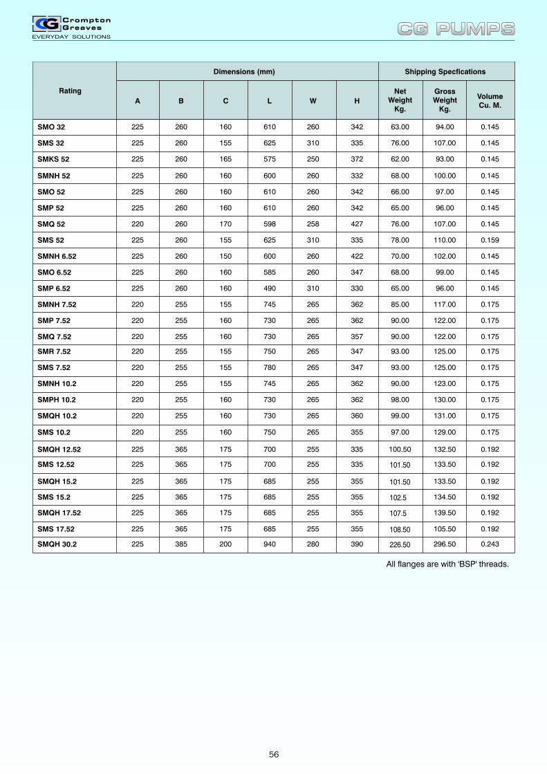
A B C L W H
NetWeight
Kg.
GrossWeight
Kg.
VolumeCu. M.
Rating
Dimensions (mm) Shipping Specfications
SMO 32 225 260 160 610 260 342 63.00 94.00 0.145
SMS 32 225 260 155 625 310 335 76.00 107.00 0.145
SMKS 52 225 260 165 575 250 372 62.00 93.00 0.145
SMNH 52 225 260 160 600 260 332 68.00 100.00 0.145
SMO 52 225 260 160 610 260 342 66.00 97.00 0.145
SMP 52 225 260 160 610 260 342 65.00 96.00 0.145
SMQ 52 220 260 170 598 258 427 76.00 107.00 0.145
SMS 52 225 260 155 625 310 335 78.00 110.00 0.159
SMNH 6.52 225 260 150 600 260 422 70.00 102.00 0.145
SMO 6.52 225 260 160 585 260 347 68.00 99.00 0.145
SMP 6.52 225 260 160 490 310 330 65.00 96.00 0.145
SMNH 7.52 220 255 155 745 265 362 85.00 117.00 0.175
SMP 7.52 220 255 160 730 265 362 90.00 122.00 0.175
SMQ 7.52 220 255 160 730 265 357 90.00
93.00
122.00 0.175
SMR 7.52 220 255 155 750 265 347 125.00 0.175
SMS 7.52 220 255 155 780 265 347 93.00 125.00 0.175
SMNH 10.2 220 255 155 745 265 362 90.00 123.00 0.175
SMPH 10.2 220 255 160 730 265 362 98.00 130.00 0.175
SMQH 10.2 220 255 160 730 265 360 99.00 131.00 0.175
SMS 10.2
SMQH 12.52
SMS 12.52
SMS 17.52
SMQH 15.2
SMQH 17.52
SMQH 30.2
SMS 15.2
220
225
225
225
225
225
225
225
255
365
365
365
365
365
385
365
160
175
175
175
175
175
200
175
750
700
700
685
685
685
940
685
265
255
255
255
255
255
280
255
355
335
335
355
355
355
390
355
97.00
100.50
101.50
108.50
101.50
107.5
226.50
102.5
129.00
132.50
133.50
105.50
133.50
139.50
296.50
134.50
0.175
0.192
0.192
0.192
0.192
0.192
0.243
0.192
All flanges are with 'BSP' threads.
CG PUMPSCG PUMPS
56
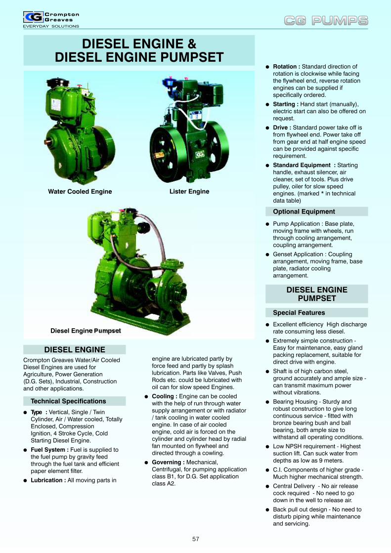
Special Features
lExcellent efficiency High discharge rate consuming less diesel.
lExtremely simple construction - Easy for maintenance, easy gland packing replacement, suitable for direct drive with engine.
lShaft is of high carbon steel, ground accurately and ample size - can transmit maximum power without vibrations.
lBearing Housing - Sturdy and robust construction to give long continuous service - fitted with bronze bearing bush and ball bearing, both ample size to withstand all operating conditions.
lLow NPSH requirement - Highest suction lift. Can suck water from depths as low as 9 meters.
lC.I. Components of higher grade - Much higher mechanical strength.
lCentral Delivery - No air release cock required - No need to go down in the well to release air.
lBack pull out design - No need to disturb piping while maintenance and servicing.
Optional Equipment
lPump Application : Base plate, moving frame with wheels, run through cooling arrangement, coupling arrangement.
lGenset Application : Coupling arrangement, moving frame, base plate, radiator cooling arrangement.
lRotation : Standard direction of rotation is clockwise while facing the flywheel end, reverse rotation engines can be supplied if specifically ordered.
lStarting : Hand start (manually), electric start can also be offered on request.
lDrive : Standard power take off is from flywheel end. Power take off from gear end at half engine speed can be provided against specific requirement.
lStandard Equipment : Starting handle, exhaust silencer, air cleaner, set of tools. Plus drive pulley, oiler for slow speed engines. (marked * in technical data table)
DIESEL ENGINEPUMPSET
engine are lubricated partly byforce feed and partly by splash lubrication. Parts like Valves, Push Rods etc. could be lubricated with oil can for slow speed Engines.
lCooling : Engine can be cooled with the help of run through water supply arrangement or with radiator / tank cooling in water cooled engine. In case of air cooledengine, cold air is forced on thecylinder and cylinder head by radialfan mounted on flywheel anddirected through a cowling.
lGoverning : Mechanical, Centrifugal, for pumping application class B1, for D.G. Set application class A2.
Crompton Greaves Water/Air Cooled Diesel Engines are used for Agriculture, Power Generation (D.G. Sets), Industrial, Construction and other applications.
Technical Specifications
lType : Vertical, Single / Twin Cylinder, Air / Water cooled, Totally Enclosed, Compression Ignition, 4 Stroke Cycle, Cold Starting Diesel Engine.
lFuel System : Fuel is supplied to the fuel pump by gravity feed through the fuel tank and efficient paper element filter.
lLubrication : All moving parts in
DIESEL ENGINE
DIESEL ENGINE &DIESEL ENGINE PUMPSET
Water Cooled Engine Lister Engine
Diesel Engine Pumpset
CG PUMPSCG PUMPS
57
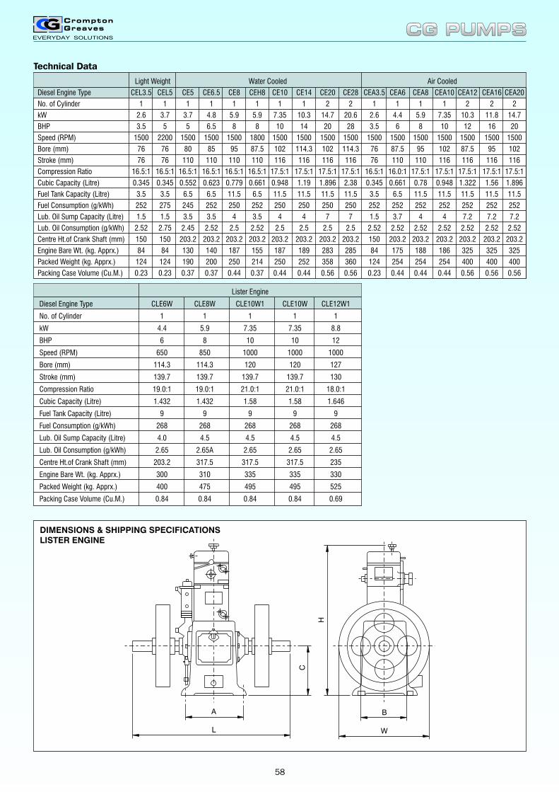
Light Weight Water Cooled Air Cooled
Diesel Engine Type CEL3.5 CEL5 CE5 CE6.5 CE8 CEH8 CE10 CE14 CE20 CE28 CEA3.5 CEA6 CEA8 CEA10 CEA12 CEA16 CEA20
No. of Cylinder 1 1 1 1 1 1 1 1 2 2 1 1 1 1 2 2 2
kW 2.6 3.7 3.7 4.8 5.9 5.9 7.35 10.3 14.7 20.6 2.6 4.4 5.9 7.35 10.3 11.8 14.7
BHP 3.5 5 5 6.5 8 8 10 14 20 28 3.5 6 8 10 12 16 20
Speed (RPM) 1500 2200 1500 1500 1500 1800 1500 1500 1500 1500 1500 1500 1500 1500 1500 1500 1500
Bore (mm) 76 76 80 85 95 87.5 102 114.3 102 114.3 76 87.5 95 102 87.5 95 102
Stroke (mm) 76 76 110 110 110 110 116 116 116 116 76 110 110 116 116 116 116
Compression Ratio 16.5:1 16.5:1 16.5:1 16.5:1 16.5:1 16.5:1 17.5:1 17.5:1 17.5:1 17.5:1 16.5:1 16.0:1 17.5:1 17.5:1 17.5:1 17.5:1 17.5:1
Cubic Capacity (Litre) 0.345 0.345 0.552 0.623 0.779 0.661 0.948 1.19 1.896 2.38 0.345 0.661 0.78 0.948 1.322 1.56 1.896
Fuel Tank Capacity (Litre) 3.5 3.5 6.5 6.5 11.5 6.5 11.5 11.5 11.5 11.5 3.5 6.5 11.5 11.5 11.5 11.5 11.5
Fuel Consumption (g/kWh) 252 275 245 252 250 252 250 250 250 250 252 252 252 252 252 252 252
Lub. Oil Sump Capacity (Litre) 1.5 1.5 3.5 3.5 4 3.5 4 4 7 7 1.5 3.7 4 4 7.2 7.2 7.2
Lub. Oil Consumption (g/kWh) 2.52 2.75 2.45 2.52 2.5 2.52 2.5 2.5 2.5 2.5 2.52 2.52 2.52 2.52 2.52 2.52 2.52
Centre Ht.of Crank Shaft (mm) 150 150 203.2 203.2 203.2 203.2 203.2 203.2 203.2 203.2 150 203.2 203.2 203.2 203.2 203.2 203.2
Engine Bare Wt. (kg. Apprx.) 84 84 130 140 187 155 187 189 283 285 84 175 188 186 325 325 325
Packed Weight (kg. Apprx.) 124 124 190 200 250 214 250 252 358 360 124 254 254 254 400 400 400
Packing Case Volume (Cu.M.) 0.23 0.23 0.37 0.37 0.44 0.37 0.44 0.44 0.56 0.56 0.23 0.44 0.44 0.44 0.56 0.56 0.56
Lister Engine
Diesel Engine Type CLE6W CLE8W CLE10W1 CLE10W CLE12W1
No. of Cylinder 1 1 1 1 1
kW 4.4 5.9 7.35 7.35 8.8
BHP 6 8 10 10 12
Speed (RPM) 650 850 1000 1000 1000
Bore (mm) 114.3 114.3 120 120 127
Stroke (mm) 139.7 139.7 139.7 139.7 130
Compression Ratio 19.0:1 19.0:1 21.0:1 21.0:1 18.0:1
Cubic Capacity (Litre) 1.432 1.432 1.58 1.58 1.646
Fuel Tank Capacity (Litre) 9 9 9 9 9
Fuel Consumption (g/kWh) 268 268 268 268 268
Lub. Oil Sump Capacity (Litre) 4.0 4.5 4.5 4.5 4.5
Lub. Oil Consumption (g/kWh) 2.65 2.65A 2.65 2.65 2.65
Centre Ht.of Crank Shaft (mm) 203.2 317.5 317.5 317.5 235
Engine Bare Wt. (kg. Apprx.) 300 310 335 335 330
Packed Weight (kg. Apprx.) 400 475 495 495 525
Packing Case Volume (Cu.M.) 0.84 0.84 0.84 0.84 0.69
DIMENSIONS & SHIPPING SPECIFICATIONSLISTER ENGINE
H
L
A
W
B
C
Technical Data
CG PUMPSCG PUMPS
58
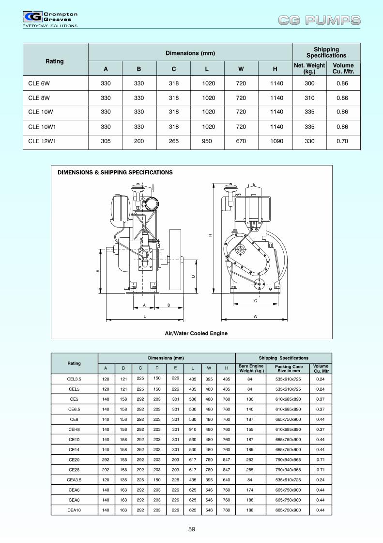
1020
1020
Dimensions (mm)
CLE 6W
CLE 8W
Rating
L
720
720
W H
1140
1140
300
310
330
330
A
330
330
B C
318
318
11401020CLE 10W 720 335318330 330 0.86
11401020CLE 10W1 720 335318330 330 0.86
950CLE 12W1 670 1090 330305 200 265 0.70
0.86
0.86
Net. Weight(kg.)
VolumeCu. Mtr.
ShippingSpecifications
Air/Water Cooled Engine
L
D
A B
H
C
W
E
Rating
Dimensions (mm) Shipping Specifications
DA C
150120 225 84
150225120 84
292 203140 130
292 203140 187
292 203140 140
292 203140 155
292 203140 187
760158 530
158
158
158
158
530
530
910
530
760
760
760
760
121
121
B L
435
435
H
435
435
610x685x890
535x610x725
0.37
0.44
0.37
0.37
0.44
0.24
0.24
0.44
0.71
0.44
0.44
0.24
0.44
0.71617158 847292292 203 285
625
625
435
625140
120
140
140
203
150
203
203
292
225
292
292
174
84
188
188163
163
135
163
760
760
640
760
530
617
CEL5
CEL3.5
CE5
CE8
CE6.5
CEH8
CE10
CE28
CEA10
CEA8
CEA3.5
CEA6
CE14
CE20 292
140
203
203
292
292
283
189158
158
760
847
535x610x725
610x685x890
665x750x900
610x685x890
665x750x900
665x750x900
790x940x965
790x940x965
535x610x725
665x750x900
665x750x900
665x750x900
Bare EngineWeight (kg.) Size in mm
Packing CaseCu. MtrVolumeW
395
480
780
780
395
546
546
546
480
480
480
480
480
480
E
226
226
226
226
203
203
226
226
301
301
301
301
301
301
CG PUMPSCG PUMPS
DIMENSIONS & SHIPPING SPECIFICATIONS
59
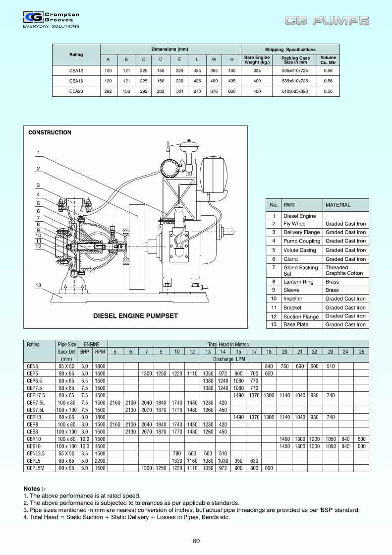
Rating
Dimensions (mm) Shipping Specifications
DA C
150120 225 400
150225120 325
292 203292 400800158 870
121
121
B L
435
435
H
435
435
610x685x890
535x610x725
0.56
0.56
0.56
CEA16
CEA12
CEA20
535x610x725
Bare EngineWeight (kg.) Size in mm
Packing CaseCu. MtrVolumeW
395
480
670
E
226
226
301
Sleeve Brass9
Impeller10
Bracket Graded Cast Iron11
Suction Flange12
Base Plate13 Graded Cast Iron
Graded Cast Iron
Graded Cast Iron
Volute Casing
Gland PackingSet
Gland Graded Cast Iron
ThreadedGraphite Cotton
Graded Cast Iron5
6
7
Lantern Ring Brass8
No.
2
1
Fly Wheel
Diesel Engine
PART MATERIAL
_
4
3 Delivery Flange
Pump Coupling
Graded Cast Iron
Graded Cast Iron
Graded Cast Iron
CONSTRUCTION
DIESEL ENGINE PUMPSET
1
2
3
4
5
6
10
13
789
1112
Rating Pipe ENGINE Total Head in Metres
Sucx Del BHP RPM 5 6 7 9 10 12 13 14 15 17 18 20 21 22 23 24 25
(mm) Discharge LPM
CEN5 65 X 50 5.0 1800 840 750 690 600 510
CEP5 80 x 65 5.0 1500 1300 1250 1220 1110 1050 972 900 700 600
CEP6.5 80 x 65 6.5 1500 1380 1240 1080 770
CEP7.5 80 x 65 7.5 1500 1380 1240 1080 770
CEPH7.5 80 x 65 7.5 1500 1490 1370 1300 1140 1040 930 740
CER7.5L 100 x 80 7.5 1500 2160 2100 2040 1840 1740 1450 1230 420
CES7.5L 100 x 100 7.5 1500 2130 2070 1870 1770 1480 1260 450
CEPH8 80 x 65 8.0 1800 1490 1370 1300 1140 1040 930 740
CER8 100 x 80 8.0 1500 2160 2100 2040 1840 1740 1450 1230 420
CES8 100 x 100 8.0 1500 2130 2070 1870 1770 1480 1260 450
CER10 100 x 80 10.0 1500 1400 1300 1200 1050 840 600
CES10 100 x 100 10.0 1500 1400 1300 1200 1050 840 600
CENL3.5 65 X 50 3.5 1500 780 660 600 510
CEPL5 80 x 65 5.0 2200 1320 1160 1080 1030 950 630
CEPL5M 80 x 65 5.0 1500 1300 1250 1220 1110 1050 972 900 800 600
Size
Notes :-1. The above performance is at rated speed.2. The above performance is subjected to tolerances as per applicable standards.3. Pipe sizes mentioned in mm are nearest conversion of inches, but actual pipe threadings are provided as per 'BSP' standard.4. Total Head = Static Suction + Static Delivery + Losses in Pipes, Bends etc.
CG PUMPSCG PUMPS
60
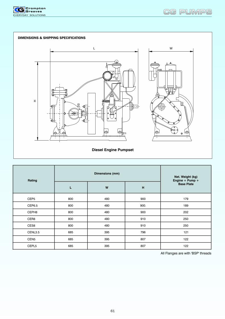
All Flanges are with 'BSP' threads
L W
H
Rating
Dimensions (mm)Net. Weight (kg)
Engine + Pump +Base Plate
HL W
807685 395 122
796395685 121
480 900800 179
480 900800 202
480 900.800 189
480 910800 250
480 910800 250
CEN5
CENL3.5
CEP5
CEPH8
CEP6.5
CER8
CES8
CEPL5 685 395 807 122
Diesel Engine Pumpset
CG PUMPSCG PUMPS
DIMENSIONS & SHIPPING SPECIFICATIONS
61
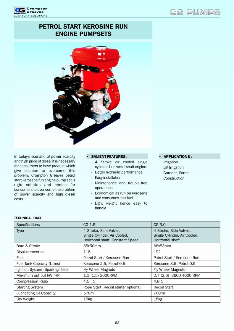
PETROL START KEROSINE RUNENGINE PUMPSETS
In today's scenario of power scarcity and high price of diesel it is necessary for consumers to have product which give solution to overcome this problem. Crompton Greaves petrol start kerosene run engine pump set is right solution and choice for consumers to over come the problem of power scarcity and high diesel costs.
• SALIENT FEATURES :
- 4 Stroke air cooled single cylinder, horizontal shaft engine.
- Better hydraulic performance.
- Easy installation
- Maintenance and trouble-free operations
- Economical as run on kerosene and consumes less fuel.
- Light weight hence easy to handle
• APPLICATIONS :
Irrigation
Lift Irrigation
Gardens, Farms
Construction
Specifications CG 1.5 CG 3.0
Type 4-Stroke, Side Valves, 4-Stroke, Side Valves,Single Cylinder, Air Cooled, Single Cylinder, Air Cooled,Horizontal shaft, Constant Speed, Horizontal shaft
Bore & Stroke 55x50mm 68x53mm
Displacement cc 118 192
Fuel Petrol Start / Kerosene Run Petrol Start / Kerosene Run
Fuel Tank Capacity (Litres) Kerosene 2.5, Petrol-0.5 Kerosene 3.5, Petrol-0.5
Ignition System (Spark Ignited) Fly Wheel Magneto Fly Wheel Magneto
Maximum out put kW (HP) 1.1 (1.5) 3000RPM 2.7 (3.6) 3600 4000 RPM
Compression Ratio 4.5 : 1 4.8:1
Starting System Rope Start (Recoil starter optional) Recoil Start
Lubricating Oil Capacity 570ml 700ml
Dry Weight 15kg 18kg
CG PUMPSCG PUMPS
TECHNICAL DATA
62
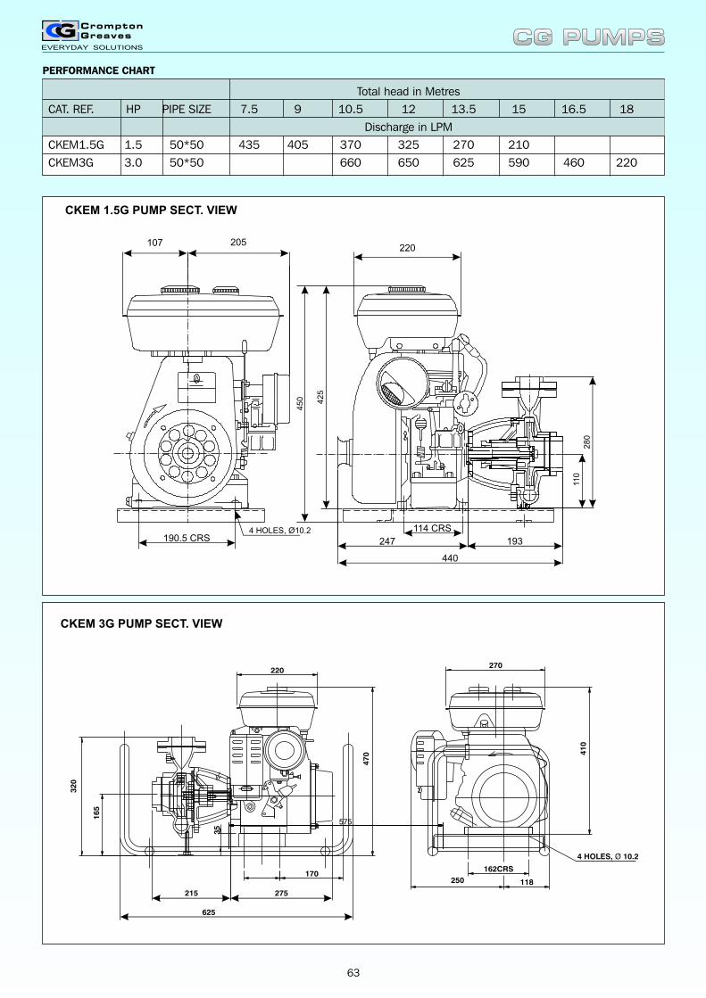
Total head in Metres
CAT. REF. HP PIPE SIZE 7.5 9 10.5 12 13.5 15 16.5 18
Discharge in LPM
CKEM1.5G 1.5 50*50 435 405 370 325 270 210
CKEM3G 3.0 50*50 660 650 625 590 460 220
220
625
470 4
10
118250
270
275215
165
320
170162CRS
575
35
4 HOLES, Ø 10.2
CKEM 3G PUMP SECT. VIEW
CKEM 1.5G PUMP SECT. VIEW
247 193
440
190.5 CRS
205107
4 HOLES, Ø10.2
45
0 42
5
28
0
110
114 CRS
220
CG PUMPSCG PUMPS
63
PERFORMANCE CHART
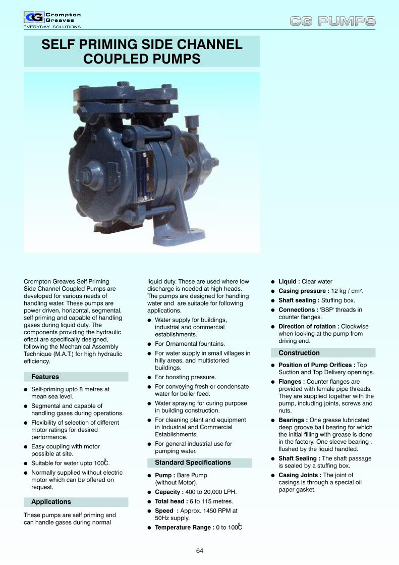
SELF PRIMING SIDE CHANNELCOUPLED PUMPS
Crompton Greaves Self PrimingSide Channel Coupled Pumps are developed for various needs of handling water. These pumps are power driven, horizontal, segmental, self priming and capable of handling gases during liquid duty. The components providing the hydraulic effect are specifically designed, following the Mechanical Assembly Technique (M.A.T.) for high hydraulic efficiency.
lSelf-priming upto 8 metres at mean sea level.
lSegmental and capable of handling gases during operations.
lFlexibility of selection of different motor ratings for desired performance.
lEasy coupling with motorpossible at site.
0lSuitable for water upto 100C.
lNormally supplied without electric motor which can be offered on request.
Features
liquid duty. These are used where low discharge is needed at high heads. The pumps are designed for handling water and are suitable for following applications.
lWater supply for buildings,industrial and commercialestablishments.
lFor Ornamental fountains.
lFor water supply in small villages in hilly areas, and multistoried buildings.
lFor boosting pressure.
lFor conveying fresh or condensate water for boiler feed.
lWater spraying for curing purpose in building construction.
lFor cleaning plant and equipment in Industrial and Commercial Establishments.
lFor general industrial use for pumping water.
Applications
lLiquid : Clear water
lCasing pressure : 12 kg / cm².
lShaft sealing : Stuffing box.
lConnections : 'BSP' threads incounter flanges.
lDirection of rotation : Clockwise when looking at the pump from driving end.
Construction
lPosition of Pump Orifices : Top Suction and Top Delivery openings.
lFlanges : Counter flanges are provided with female pipe threads. They are supplied together with the pump, including joints, screws and nuts.
lBearings : One grease lubricated deep groove ball bearing for which the initial filling with grease is done in the factory. One sleeve bearing , flushed by the liquid handled.
lShaft Sealing : The shaft passage is sealed by a stuffing box.
lCasing Joints : The joint of casings is through a special oil paper gasket.
These pumps are self priming andcan handle gases during normal
Standard Specifications
lPump : Bare Pump(without Motor).
lCapacity : 400 to 20,000 LPH.
lTotal head : 6 to 115 metres.
lSpeed : Approx. 1450 RPM at 50Hz supply.
0lTemperature Range : 0 to 100C
CG PUMPSCG PUMPS
64
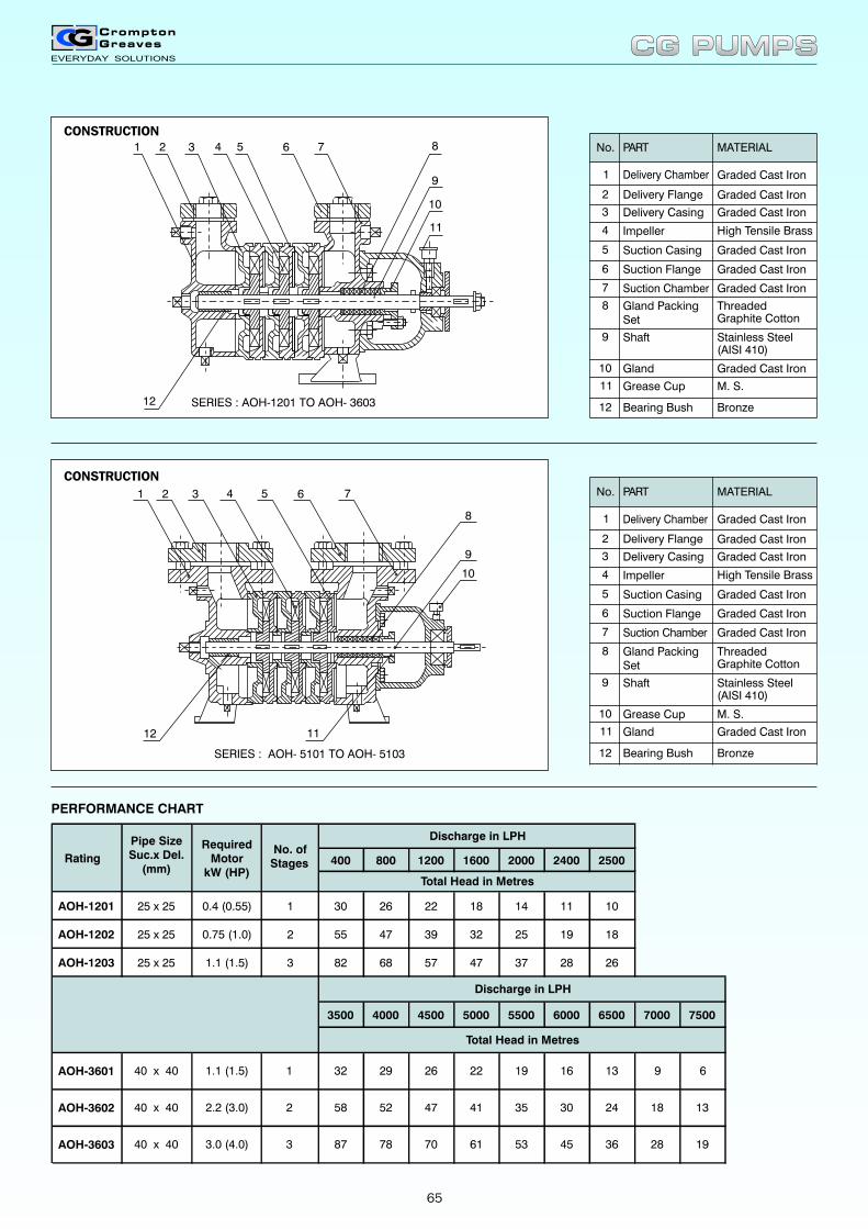
No.
2
1
Delivery Flange
Delivery Chamber
PART MATERIAL
Graded Cast Iron
4
3
Suction Casing
Suction Chamber
Suction Flange
Delivery Casing
Impeller
Graded Cast Iron
Graded Cast Iron
High Tensile Brass
Graded Cast Iron
Graded Cast Iron
Graded Cast Iron5
6
7
Gland PackingSet
ThreadedGraphite Cotton
8
Shaft Stainless Steel(AISI 410)
9
Gland Graded Cast Iron10
Grease Cup M. S.11
Bearing Bush Bronze12
PERFORMANCE CHART
400 800 1200 1600 2000 2400 2500
AOH-1201 30 26 22 18 14 11 10
AOH-1202 55 47 39 32 25 19 18
AOH-1203 82 68 57 47 37 28 26
3500 4000 4500 5000 5500 6000 6500 7000 7500
Rating
0.4 (0.55)
0.75 (1.0)
1.1 (1.5)
RequiredMotor
kW (HP)
25 x 25
25 x 25
25 x 25
Pipe SizeSuc.x Del.
(mm)
1
2
3
No. ofStages
Discharge in LPH
Total Head in Metres
Discharge in LPH
Total Head in Metres
1932 16 13 9 6
58 52 47 41
29 26 22
35 30 24 18
70 61 1953 45 36 28
1.1 (1.5)
2.2 (3.0)
3.0 (4.0)
AOH-3602
AOH-3603
AOH-3601 1
2
3
40 x 40
40 x 40
40 x 40
13
87 78
No.
2
1
Delivery Flange
PART MATERIAL
Graded Cast Iron
4
3
Suction Casing
Suction Chamber
Suction Flange
Delivery Casing
Impeller
Graded Cast Iron
Graded Cast Iron
High Tensile Brass
Graded Cast Iron
Graded Cast Iron
Graded Cast Iron5
6
7
Gland PackingSet
ThreadedGraphite Cotton
8
Shaft Stainless Steel(AISI 410)
9
Grease Cup
Graded Cast Iron
10
Gland
M. S.
11
Bearing Bush Bronze12
Delivery Chamber
CG PUMPSCG PUMPS
1 2 3 4 5 6 7 8
9
12
11
10
SERIES : AOH-1201 TO AOH- 3603
CONSTRUCTION
SERIES : AOH- 5101 TO AOH- 5103
1 2 3 4 5 6 7
8
9
12
10
11
CONSTRUCTION
65
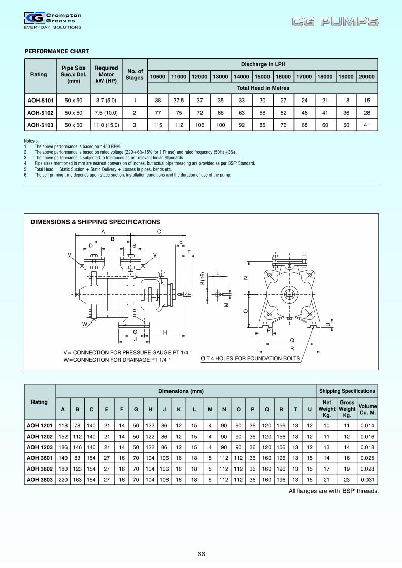
DIMENSIONS & SHIPPING SPECIFICATIONS
PERFORMANCE CHART
Notes :- 1. The above performance is based on 1450 RPM.. The above performance is based on . The above performance is subjected to tolerances as per relevant Indian Standards.
4. Pipe sizes mentioned in mm are nearest conversion of inches, but actual pipe threading are provided as per 'BSP' Standard.5. Total Head = Static Suction + Static Delivery + Losses in pipes, bends etc.6. The self priming time depends upon static suction, installation conditions and the duration of use of the pump.
2 rated voltage (220+6%-15% for 1 Phase) and rated frequency (50Hz+3%).3
66
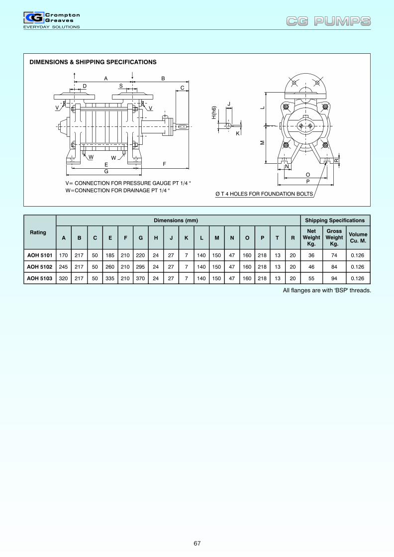
All flanges are with 'BSP' threads.
A B C E F G H J K L M N O P T R
NetWeight
Kg.
GrossWeight
Kg.
VolumeCu. M.
AOH 5101 170 217 50 185 210 220 24 27 7 140 150 47 160 218 13 20 36 74 0.126
AOH 5102 245 217 50 260 210 295 24 27 7 140 150 47 160 218 13 20 46 84 0.126
AOH 5103 320 217 50 335 210 370 24 27 7 140 150 47 160 218 13 20 55 94 0.126
Dimensions (mm)
Rating
Shipping Specifications
V= CONNECTION FOR PRESSURE GAUGE PT 1/4 "
W=CONNECTION FOR DRAINAGE PT 1/4 "
LM
J
K
H(h
6)
N
P
O
R
A B
D S C
E
G
F
V V
WW
Ø T 4 HOLES FOR FOUNDATION BOLTS
CG PUMPSCG PUMPS
DIMENSIONS & SHIPPING SPECIFICATIONS
67
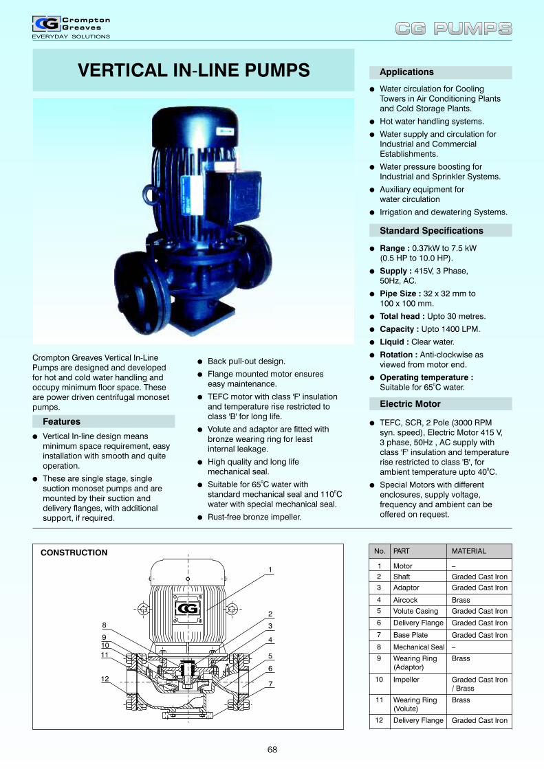
Crompton Greaves Vertical In-Line Pumps are designed and developed for hot and cold water handling and occupy minimum floor space. These are power driven centrifugal monoset pumps.
lVertical In-line design means minimum space requirement, easyinstallation with smooth and quiteoperation.
lThese are single stage, singlesuction monoset pumps and aremounted by their suction anddelivery flanges, with additionalsupport, if required.
Features
lWater circulation for CoolingTowers in Air Conditioning Plantsand Cold Storage Plants.
lHot water handling systems.
lWater supply and circulation for Industrial and Commercial Establishments.
lWater pressure boosting for Industrial and Sprinkler Systems.
lAuxiliary equipment forwater circulation
lIrrigation and dewatering Systems.
Applications
lRange : 0.37kW to 7.5 kW(0.5 HP to 10.0 HP).
lSupply : 415V, 3 Phase,50Hz, AC.
lPipe Size : 32 x 32 mm to100 x 100 mm.
lTotal head : Upto 30 metres.
lCapacity : Upto 1400 LPM.
lLiquid : Clear water.
lRotation : Anti-clockwise asviewed from motor end.
lOperating temperature :0Suitable for 65 C water.
Standard Specifications
lTEFC, SCR, 2 Pole (3000 RPMsyn. speed), Electric Motor 415 V,3 phase, 50Hz , AC supply withclass 'F' insulation and temperaturerise restricted to class 'B', for
0ambient temperature upto 40 C.
lSpecial Motors with differentenclosures, supply voltage,frequency and ambient can beoffered on request.
Electric Motor
lBack pull-out design.
lFlange mounted motor ensureseasy maintenance.
lTEFC motor with class 'F' insulation and temperature rise restricted to class 'B' for long life.
lVolute and adaptor are fitted with bronze wearing ring for least internal leakage.
lHigh quality and long life mechanical seal.
l0Suitable for 65 C water with
0standard mechanical seal and 110 Cwater with special mechanical seal.
lRust-free bronze impeller.
No.
2
1
Shaft
Motor
PART MATERIAL
_
4
3
Volute Casing
Base Plate
Delivery Flange
Adaptor
Aircock
Graded Cast Iron
Graded Cast Iron
Brass
Graded Cast Iron
Graded Cast Iron
Graded Cast Iron5
6
7
Mechanical Seal _8
Wearing Ring(Adaptor)
Brass9
Impeller Graded Cast Iron/ Brass
10
Wearing Ring(Volute)
Brass11
Delivery Flange Graded Cast Iron12
1
3
4
6
7
8
10
12
2
511
9
VERTICAL IN-LINE PUMPS
CG PUMPSCG PUMPS
CONSTRUCTION
68

Notes :-
1. The above performance is based on rated voltage (415+6%-15% for 1 Phase) and rated frequency (50Hz+3%).
2. The above performance is subjected to tolerances as per applicable standards.
3 Pipe sizes mentioned in mm are nearest conversion of inches, but actual pipe threadings are provided as per 'BSP' standard
4 Total Head = Static Suction + Static Delivery + Losses in pipes, bends etc.
PERFORMANCE CHART
All flanges are with 'BSP' threads.
W
F C
L
VIEW -'X'
H
E
`X'
A
B
BASE PLATE
Ø D 4 HOLES FORFOUNDATION BOLTS
ØK
ØJ
ØG
Ø M 4 HOLES EQUISPACED ON PCD N.
FLANGE
10 12 14 16 18 20 22 24 26 28 30
ILM052/A 135 105 50
ILM12/A 240 215 185 130
ILM22/A 400 360 315 250
ILM32/A 575 515 440 340
ILM52 /A 875 800 720 550
ILM7.52/A 1300 1260 1200 1110 1000 850
ILM10.2/A 1400 1320 1250 1180 1090 1000 900
Total Head in Metres
Discharge in LPM
Rating
0.37 (0.5)
0.75 (1.0)
1.5 (2.0)
2.2 (3.0)
3.7 (5.0)
5.5 (7.5)
7.5 (10.0)
MotorkW (HP)
32 x 32
40 x 40
50 x 50
65 x 65
80 x 80
100 x 100
100 x 100
Pipe sizeSuc. x Del.
(mm)
A B C D E F G J K M PCD'N'
L W H
NetWeight
Kg.
GrossWeight
Kg.
VolumeCu. M.
ILM052/A 120 112 140 12 75 140 32 70 120 14 90 280 200 370 24 41.5 0.08
ILM12/A 120 115 150 12 82 150 40 80 130 14 100 300 210 430 33 54 0.105
ILM22/A 120 120 160 12 100 150 50 90 140 14 110 310 265 475 48 74 0.138
ILM32/A 130 120 180 12 115 165 65 115 185 18 145 345 285 510 59 88 0.16
ILM52/A 135 120 190 12 130 185 80 128 190 18 150 375 315 550 71 101.5 0.182
ILM7.52/A 178 130 255 12 140 235 100 148 210 18 170 490 340 615 101 140.5 0.265
ILM10.2/A 178 130 255 12 140 253 100 148 210 18 170 490 340 650 117 158.5 0.28
Rating
Dimensions (mm) Shipping Specifications
CG PUMPSCG PUMPS
DIMENSIONS & SHIPPING SPECIFICATIONS
69
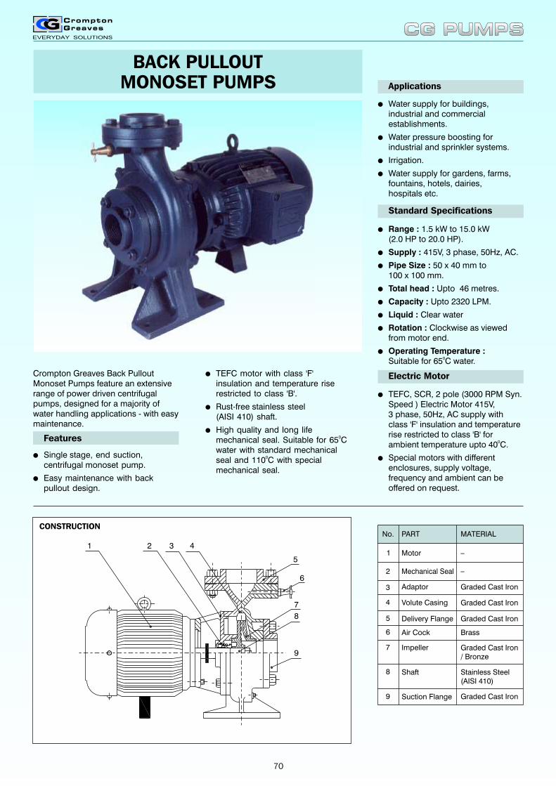
Crompton Greaves Back Pullout Monoset Pumps feature an extensive range of power driven centrifugal pumps, designed for a majority of water handling applications - with easy maintenance.
l
l
l
TEFC motor with class 'F' insulation and temperature riserestricted to class 'B'.
Rust-free stainless steel(AISI 410) shaft.
High quality and long life0mechanical seal. Suitable for 65 C
water with standard mechanical0seal and 110 C with special
mechanical seal.
Features
l
l
l
l
Water supply for buildings,industrial and commercialestablishments.
Water pressure boosting for industrial and sprinkler systems.
Irrigation.
Water supply for gardens, farms,fountains, hotels, dairies,hospitals etc.
Applications
Standard Specifications
l
l
l
l
l
l
l
l
Range : 1.5 kW to 15.0 kW(2.0 HP to 20.0 HP).
Supply : 415V, 3 phase, 50Hz, AC.
Pipe Size : 50 x 40 mm to100 x 100 mm.
Total head : Upto 46 metres.
Capacity : Upto 2320 LPM.
Liquid : Clear water
Rotation : Clockwise as viewedfrom motor end.
Operating Temperature : 0Suitable for 65 C water.
Electric Motor
l
l
TEFC, SCR, 2 pole (3000 RPM Syn. Speed ) Electric Motor 415V,3 phase, 50Hz, AC supply withclass 'F' insulation and temperaturerise restricted to class 'B' for
0ambient temperature upto 40 C.
Special motors with different enclosures, supply voltage, frequency and ambient can be offered on request.
lSingle
l
stage, end suction, centrifugal monoset pump.
Easy maintenance with backpullout design.
CONSTRUCTION
1 2 3 4
5
7
8
9
6
Shaft
Impeller
Suction Flange
Graded Cast Iron/ Bronze
Stainless Steel(AISI 410)
Graded Cast Iron
7
8
9
Motor
PART
Delivery Flange
Volute Casing
Adaptor Graded Cast Iron
MATERIAL
_
Mechanical Seal _
Graded Cast Iron
Graded Cast Iron
No.
2
1
4
3
5
Air Cock Brass6
BACK PULLOUTMONOSET PUMPS
CG PUMPSCG PUMPS
70
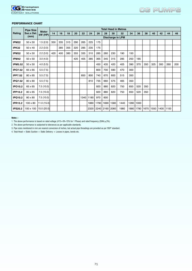
14 16 18 20 22 24 26 28 30 32 34 36 38 40 42 44 46
2240 206021602320 1670178018801980 110014001550
1440 1280 10001880 1790 1690 1580
1180 970 6001340
750 650 520 350920 880 820
820880920
465 350
350520650750
810 735 660 575
515 350800 740 670 600850
300 260 200
300
390 370 350 325
470590700800
405 250 185
450 420 405
385 365 345
435
315 285
190 150
IPQ10.2
IPR15.2
IPS20.2
IPP7.52
IPQ7.52
IPO10.2
IPP10.2
IPO7.52
IPM32
IPM5.52
310 285 260 230420
IPM42
355 335400 380
420
285 235 175 IPK32 385 355 320
265 225 175350 335 315 290 IPM22
Total Head in Metres
Discharge in LPM
Rating
7.5 (10.0)
11.0 (15.0)
15.0 (20.0)
3.0 (4.0)
4.0 (5.5)
5.5 (7.5)
5.5 (7.5)
5.5 (7.5)
7.5 (10.0)
7.5 (10.0)
2.2 (3.0)
2.2 (3.0)
1.5 (2.0)
MotorkW (HP)
100 x 100
80 x 80
100 x 80
50 x 50
50 x 50
65 x 65
80 x 65
80 x 80
65 x 65
80 x 65
50 x 50
50 x 40
Pipe SizeSuc.x Del.
(mm)
50 x 50
Notes :-
1. The above performance is based on rated voltage (415+6%-15% for 1 Phase) and rated frequency (50Hz+3%).
2. The above performance is subjected to tolerances as per applicable standards.
3. Pipe sizes mentioned in mm are nearest conversion of inches, but actual pipe threadings are provided as per 'BSP' standard.
4. Total Head = Static Suction + Static Delivery + Losses in pipes, bends etc.
CG PUMPSCG PUMPS
PERFORMANCE CHART
71
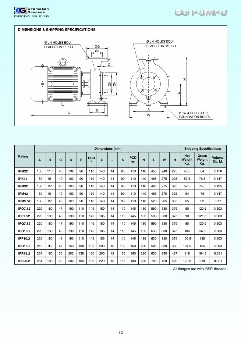
DIMENSIONS & SHIPPING SPECIFICATIONS
LA
W
H
D
BØ
N
ØK
ØE
ØG
C
Ø J 4 HOLES EQUI-
Ø 14 4 HOLES FORFOUNDATION BOLTS
SPACED ON 'F' PCD
Ø J 4 HOLES EQUI-
SPACED ON 'M' PCD
All flanges are with 'BSP' threads.
A B C D E PCD
'F' G J K
PCD
'M' N L W H
NetWeight
Kg.
GrossWeight
Kg.
VolumeCu. M.
IPM22 130 118 40 132 90 110 140 14 90 110 140 455 240 275 43.5 64 0.116
IPK32 180 151 40 163 90 110 140 14 90 110 140 495 275 325 52.5 76.5 0.147
IPM32 180 151 40 163 90 110 140 14 90 110 140 495 275 325 52.5 74.5 0.125
IPM42 180 151 40 163 90 110 140 14 90 110 140 495 275 325 54 78 0.147
IPM5.52 180 151 43 163 90 110 140 14 90 110 140 520 285 355 65 92 0.17
IPO7.52 220 180 47 190 110 145 180 14 110 145 180 590 330 375 90 120.5 0.203
IPP7.52 220 180 46 190 110 145 185 14 110 145 185 590 330 375 90 121.5 0.203
IPQ7.52 220 180 47 190 110 145 180 14 110 145 180 590 330 375 90 120.5 0.203
IPO10.2 220 180 46 190 110 145 185 14 110 145 185 630 330 375 106 137.5 0.203
IPP10.2 220 180 46 190 110 145 185 14 110 145 185 630 330 375 106.5 138 0.203
IPQ10.2 212 95 47 160 130 160 200 18 130 160 200 585 330 360 104.5 135 0.203
IPR15.2 254 180 50 202 138 160 200 18 155 180 220 630 350 427 119 164.5 0.331
IPS20.2 254 180 50 202 155 180 220 18 155 180 220 700 420 429 173.5 219 0.331
Rating
Dimensions (mm) Shipping Specifications
CG PUMPSCG PUMPS
72
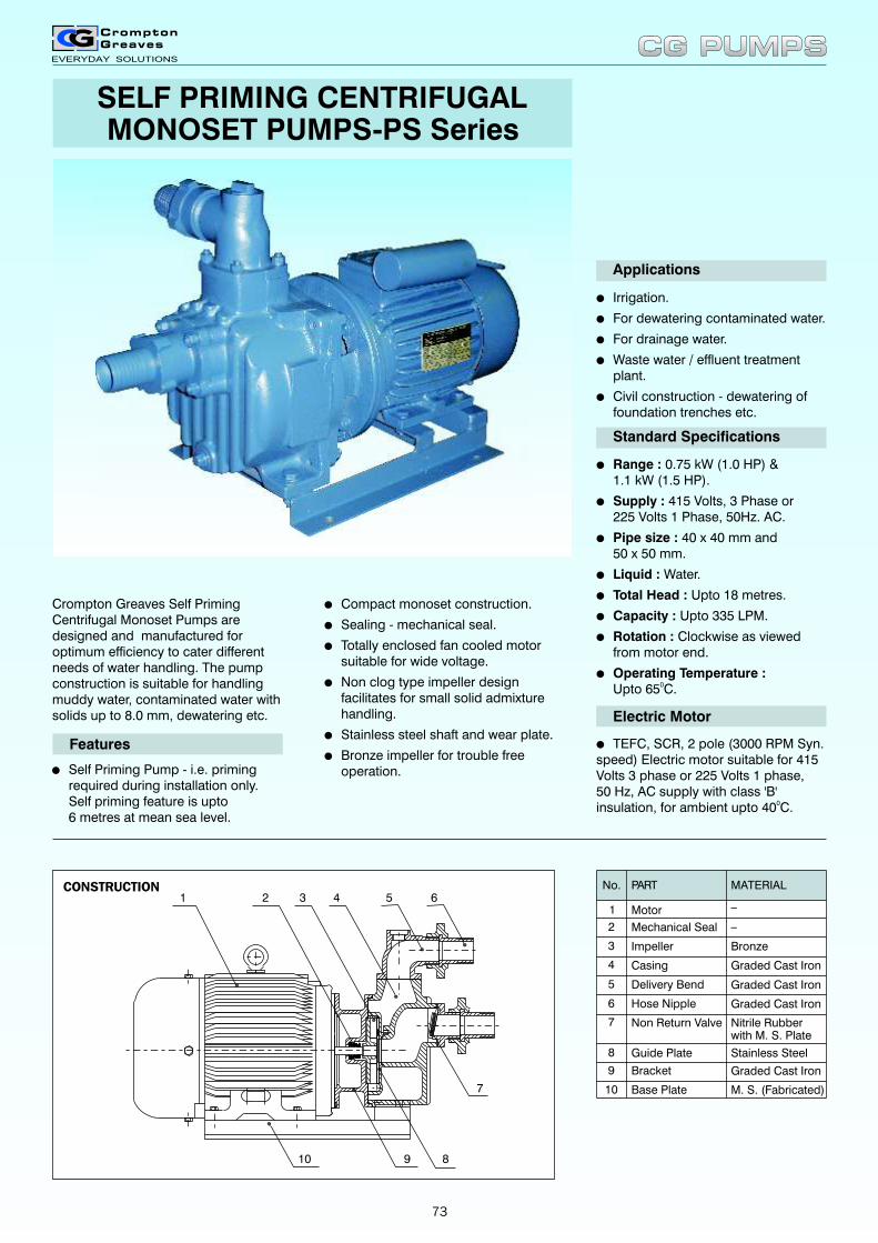
1 2 3 4 5 6
7
8910
Crompton Greaves Self Priming Centrifugal Monoset Pumps are designed and manufactured for optimum efficiency to cater different needs of water handling. The pump construction is suitable for handling muddy water, contaminated water with solids up to 8.0 mm, dewatering etc.
lSelf Priming Pump - i.e. priming required during installation only.Self priming feature is upto6 metres at mean sea level.
Features
lIrrigation.
lFor dewatering contaminated water.
lFor drainage water.
lWaste water / effluent treatment plant.
lCivil construction - dewatering offoundation trenches etc.
Applications
Standard Specifications
lRange : 0.75 kW (1.0 HP) &1.1 kW (1.5 HP).
lSupply : 415 Volts, 3 Phase or225 Volts 1 Phase, 50Hz. AC.
lPipe size : 40 x 40 mm and50 x 50 mm.
lLiquid : Water.
lTotal Head : Upto 18 metres.
lCapacity : Upto 335 LPM.
lRotation : Clockwise as viewedfrom motor end.
lOperating Temperature :0Upto 65 C.
Electric Motor
lTEFC, SCR, 2 pole (3000 RPM Syn. speed) Electric motor suitable for 415 Volts 3 phase or 225 Volts 1 phase,50 Hz, AC supply with class 'B' insulation, for ambient upto 40 C.0
CONSTRUCTION
lCompact monoset construction.
lSealing - mechanical seal.
lTotally enclosed fan cooled motor suitable for wide voltage.
lNon clog type impeller design facilitates for small solid admixture handling.
lStainless steel shaft and wear plate.
lBronze impeller for trouble free operation.
No.
2
1
Mechanical Seal
Motor
PART MATERIAL
_
4
3
Delivery Bend
Non Return Valve
Hose Nipple
Impeller
Casing
Bronze
Graded Cast Iron
Graded Cast Iron
Nitrile Rubberwith M. S. Plate
Graded Cast Iron5
6
7
Guide Plate Stainless Steel8
Bracket Graded Cast Iron9
Base Plate M. S. (Fabricated)10
_
SELF PRIMING CENTRIFUGALMONOSET PUMPS-PS Series
CG PUMPSCG PUMPS
73
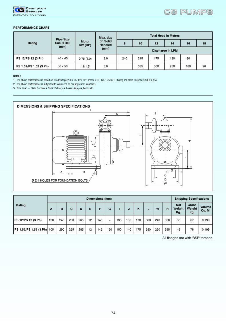
Notes :-
1. The above performance is based on rated voltage(220+6%-15% for 1 Phase 415+6%-15% for 3 Phase) and rated frequency (50Hz+3%).
2. The above performance is subjected to tolerances as per applicable standards.
3. Total Head = Static Suction + Static Delivery + Losses in pipes, bends etc.
NetWeight
Kg.
GrossWeight
Kg.
VolumeCu. M.
PS 12/PS 12 (3 Ph) 38 67 0.199
PS 1.52/PS 1.52 (3 Ph)
A
120
105
B
240
290
C
230
255
D
265
285
E
12
12
F
145
145
G
_
150
I
135
150
J
135
140
K
170
175
L
560
580
W
240
250
H
360
395 49 78 0.199
Rating
Dimensions (mm) Shipping Specifications
All flanges are with 'BSP' threads.
HF
C
D
W
G
I
JK
L
A B
Ø E 4 HOLES FOR FOUNDATION BOLTS
8 10 12 14 16 18
PS 12/PS 12 (3 Ph) 8.0 240 215 175 130 80
PS 1.52/PS 1.52 (3 Ph) 8.0 335 300 250 180 90
40 x 40
50 x 50
Pipe SizeSuc. x Del.
(mm)
Max. sizeof SolidHandled
(mm)
Total Head in Metres
Discharge in LPM
Rating
0.75 (1.0)
1.1(1.5)
MotorkW (HP)
CG PUMPSCG PUMPS
DIMENSIONS & SHIPPING SPECIFICATIONS
PERFORMANCE CHART
74
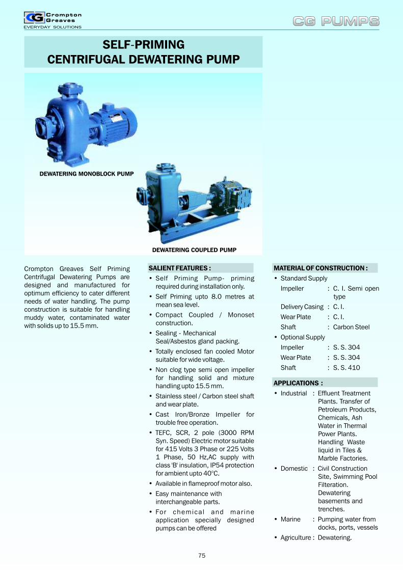
Crompton Greaves Self Priming Centrifugal Dewatering Pumps are designed and manufactured for optimum efficiency to cater different needs of water handling. The pump construction is suitable for handling muddy water, contaminated water with solids up to 15.5 mm.
SELF-PRIMINGCENTRIFUGAL DEWATERING PUMP
CG PUMPSCG PUMPS
MATERIAL OF CONSTRUCTION :
• Standard Supply
Impeller : C. I. Semi open type
Delivery Casing : C. I.
Wear Plate : C. I.
Shaft : Carbon Steel
• Optional Supply
Impeller : S. S. 304
Wear Plate : S. S. 304
Shaft : S. S. 410
SALIENT FEATURES :
• Self Priming Pump- priming required during installation only.
• Self Priming upto 8.0 metres at mean sea level.
• Compact Coupled / Monoset construction.
• Sealing - Mechanical Seal/Asbestos gland packing.
• Totally enclosed fan cooled Motor suitable for wide voltage.
• Non clog type semi open impeller for handling solid and mixture handling upto 15.5 mm.
• Stainless steel / Carbon steel shaft and wear plate.
• Cast Iron/Bronze Impeller for trouble free operation.
•
•
•
•
TEFC, SCR, 2 pole (3000 RPM Syn. Speed) Electric motor suitable for 415 Volts 3 Phase or 225 Volts 1 Phase, 50 Hz,AC supply with class 'B' insulation, IP54 protection for ambient upto 40°C.
Available in flameproof motor also.
Easy maintenance with interchangeable parts.
For chemica l and mar ine application specially designed pumps can be offered
APPLICATIONS :
• Industrial : Effluent Treatment Plants. Transfer of Petroleum Products, Chemicals, Ash Water in Thermal Power Plants. Handling Waste liquid in Tiles & Marble Factories.
• Domestic : Civil Construction Site, Swimming Pool Filteration. Dewatering basements and trenches.
• Marine : Pumping water from docks, ports, vessels
• Agriculture : Dewatering.
DEWATERING MONOBLOCK PUMP
DEWATERING COUPLED PUMP
75
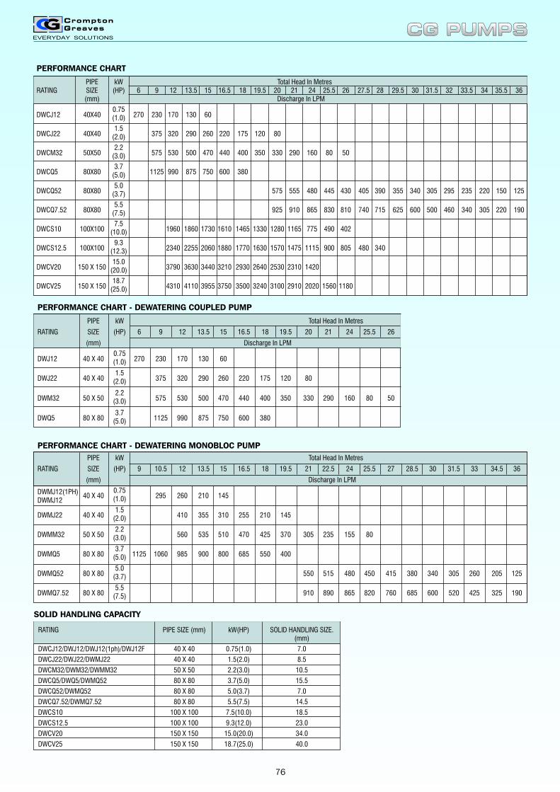
PERFORMANCE CHART
PIPE kW Total Head In MetresRATING SIZE (HP) 6 9 12 13.5 15 16.5 18 19.5 20 21 24 25.5 26 27.5 28 29.5 30 31.5 32 33.5 34 35.5 36
(mm) Discharge In LPM
0.75DWCJ12 40X40 270 230 170 130 60(1.0)
1.5 DWCJ22 40X40 375 320 290 260 220 175 120 80(2.0)
2.2DWCM32 50X50 575 530 500 470 440 400 350 330 290 160 80 50(3.0)
3.7DWCQ5 80X80 1125 990 875 750 600 380(5.0)
5.0DWCQ52 80X80 575 555 480 445 430 405 390 355 340 305 295 235 220 150 125(3.7)
5.5 DWCQ7.52 80X80 925 910 865 830 810 740 715 625 600 500 460 340 305 220 190(7.5)
7.5 DWCS10 100X100 1960 1860 1730 1610 1465 1330 1280 1165 775 490 402(10.0)
9.3 DWCS12.5 100X100 2340 2255 2060 1880 1770 1630 1570 1475 1115 900 805 480 340(12.3)
15.0DWCV20 150 X 150 3790 3630 3440 3210 2930 2640 2530 2310 1420(20.0)
18.7DWCV25 150 X 150 4310 4110 3955 3750 3500 3240 3100 2910 2020 1560 1180(25.0)
PERFORMANCE CHART - DEWATERING MONOBLOC PUMP
PIPE kW Total Head In Metres
RATING SIZE (HP) 9 10.5 12 13.5 15 16.5 18 19.5 21 22.5 24 25.5 27 28.5 30 31.5 33 34.5 36
(mm) Discharge In LPM
0.75DWMJ12(1PH)40 X 40 295 260 210 145(1.0)DWMJ12
1.5DWMJ22 40 X 40 410 355 310 255 210 145(2.0)
2.2DWMM32 50 X 50 560 535 510 470 425 370 305 235 155 80(3.0)
3.7DWMQ5 80 X 80 1125 1060 985 900 800 685 550 400(5.0)
5.0DWMQ52 80 X 80 550 515 480 450 415 380 340 305 260 205 125(3.7)
5.5DWMQ7.52 80 X 80 910 890 865 820 760 685 600 520 425 325 190(7.5)
PERFORMANCE CHART - DEWATERING COUPLED PUMP
PIPE kW Total Head In Metres
RATING SIZE (HP) 6 9 12 13.5 15 16.5 18 19.5 20 21 24 25.5 26
(mm) Discharge In LPM
0.75DWJ12 40 X 40 270 230 170 130 60(1.0)
1.5DWJ22 40 X 40 375 320 290 260 220 175 120 80(2.0)
2.2DWM32 50 X 50 575 530 500 470 440 400 350 330 290 160 80 50(3.0)
3.7DWQ5 80 X 80 1125 990 875 750 600 380(5.0)
RATING PIPE SIZE (mm) kW(HP) SOLID HANDLING SIZE.(mm)
DWCJ12/DWJ12/DWJ12(1ph)/DWJ12F 40 X 40 0.75(1.0) 7.0
DWCJ22/DWJ22/DWMJ22 40 X 40 1.5(2.0) 8.5
DWCM32/DWM32/DWMM32 50 X 50 2.2(3.0) 10.5
DWCQ5/DWQ5/DWMQ52 80 X 80 3.7(5.0) 15.5
DWCQ52/DWMQ52 80 X 80 5.0(3.7) 7.0
DWCQ7.52/DWMQ7.52 80 X 80 5.5(7.5) 14.5
DWCS10 100 X 100 7.5(10.0) 18.5
DWCS12.5 100 X 100 9.3(12.0) 23.0
DWCV20 150 X 150 15.0(20.0) 34.0
DWCV25 150 X 150 18.7(25.0) 40.0
SOLID HANDLING CAPACITY
CG PUMPSCG PUMPS
76
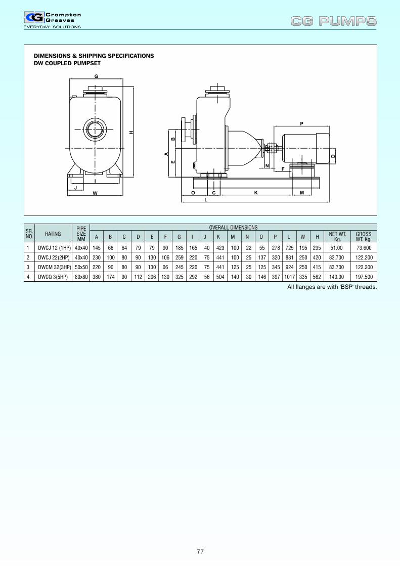
L
K
E
H
I
W
G
J
B
A
O C
P
M
NF
D
1 DWCJ 12 (1HP) 40x40 145 66 64 79 79 90 185 165 40 423 100 22 55 278 725 195 295 51.00 73.600
2 DWCJ 22(2HP) 40x40 230 100 80 90 130 106 259 220 75 441 100 25 137 320 881 250 420 83.700 122.200
3 DWCM 32(3HP) 50x50 220 90 80 90 130 06 245 220 75 441 125 25 125 345 924 250 415 83.700 122.200
4 DWCQ 3(5HP) 80x80 380 174 90 112 206 130 325 292 56 504 140 30 146 397 1017 335 562 140.00 197.500
SR.NO. NET WT.
Kg.GROSSWT. Kg.
PIPESIZEMM
RATINGA B C D E F G I J K M N O P L W H
OVERALL DIMENSIONS
CG PUMPSCG PUMPS
DIMENSIONS & SHIPPING SPECIFICATIONSDW COUPLED PUMPSET
All flanges are with 'BSP' threads.
77

Model A B C D E ØF G H J M N P R S T
DWMJ12(1PH) 114.00 359.00 145.00 67.00 577.00 107.00 1.1/2"BSP 1.1/2"BSP 100.00 201.00 132.00 136.50 309.00 98.50 103.00
DWMJ12 114.00 359.00 145.00 67.00 542.50 107.00 1.1/2"BSP 1.1/2"BSP 100.00 201.00 116.00 136.50 274.00 98.50 103.00
Ø Ø
Model A B C D E ØF G H J M N P R S T
DWMJ22 220.00 402.00 253.00 80.00 617.00 107.00 1.5"BSP 1.5"BSP 107.00 136.00 243.00 185.0 401.00 130.00 79.50
DWMM32 220.00 430.00 253.00 80.00 664.00 107.00 2"BSP 2"BSP 107.00 141.00 264.50 207.00 446.00 130.00 88.00
DWMQ5 292.00 545.00 332.00 90.00 673.00 140.00 3"BSP 3"BSP 155.55 152.00 233.00 175.00 435.00 203.00 172.50
DWMQ52 259.50 515.00 308.00 95.50 731.00 140.00 3"BSP 3"BSP 140.00 174.00 264.00 232.00 465.00 170.00 109.00
DWMQ7.52 259.50 515.00 308.00 95.50 770.00 140.00 3"BSP 3"BSP 140.00 174.00 281.00 232.00 505.00 170.00 109.00
Ø Ø
CG PUMPSCG PUMPS
DIMENSIONS & SHIPPING SPECIFICATIONSDEWATERING MONOBLOCK PUMP (1 HP)
DIMENSIONS & SHIPPING SPECIFICATIONSDEWATERING MONOBLOCK PUMP
78
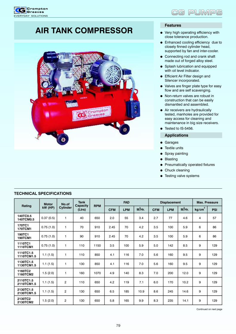
AIR TANK COMPRESSOR lVery high operating efficiency withclose tolerance production.
lEnhanced cooling efficiency due to closely finned cylinder head,supported by fan and inter-cooler.
lConnecting rod and crank shaft made out of forged alloy steel.
lSplash lubrication and equippedwith oil level indicator.
lEfficient Air Filter design and Silencer incorporated.
lValves are finger plate type for easy flow and are self scavenging.
lNon-return valves are robust in construction that can be easily dismantled and assembled.
lAir receivers are hydraulically tested, manholes are provided for easy access for cleaning and maintenance in big size receivers.
lTested to IS-5456.
Features
Applications
lGarages
lTextile units
lSpray painting
lBlasting
lPneumatically operated fixtures
lChuck cleaning
lTesting valve systems
TECHNICAL SPECIFICATIONS
Continued on next page
CFM LPM CFM LPM PSI
140TC0.5 140TCM0.5 0.37 (0.5) 1 40 650 2.0 55 3.4 2.7 77 4.6 4 57
170TC1 170TCM1
0.75 (1.0) 1 70 910 2.45 70 4.2 3.5 100 5.9 6 86
190TC1 190TCM1
0.75 (1.0) 1 90 910 2.45 70 4.2 3.5 100 5.9 6 86
1110TC1 1110TCM1 0.75 (1.0) 1 110 1150 3.5 100 5.9 5.0 142 8.5 9 129
1110TC1.5 1110TCM1.5
1.1 (1.5) 1 110 850 4.1 116 7.0 5.6 160 9.5 9 129
1130TC1.5 1130TCM1.5 1.1 (1.5) 1 130 850 4.1 116 7.0 5.6 160 9.5 9 129
1160TC2 1160TCM2 1.5 (2.0) 1 160 1070 4.9 140 8.3 7.0 200 12.0 9 129
2110TC1.5 2110TCM1.5
1.1 (1.5) 2 110 650 4.2 119 7.1 6.0 170 10.2 9 129
2130TC1.5 2130TCM1.5
1.1 (1.5) 2 130 650 6.5 185 10.9 8.6 245 14.6 9 129
2130TC2 2130TCM2
1.5 (2.0) 2 130 650 5.8 165 9.9 8.3 235 14.1 9 129
FAD Displacement Max. PressureRPMRating
Motor kW (HP)
No.of Cylinder
Tank Capacity
(Ltrs)3
M/Hr.2
kg/cm3
M/Hr.
CG PUMPSCG PUMPS
79
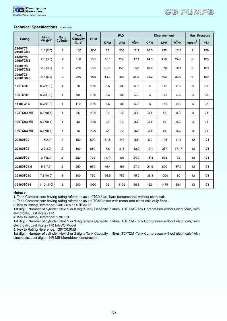
Technical Specifications (Continued)
CFM LPM 3
M/Hr. CFM LPM PSI
FAD Displacement Max. PressureRPMRating
Motor kW (HP)
No.of Cylinder
Tank Capacity
(Ltrs)
2160TC2 2160TCM2
1.5 (2.0) 2 160 600 7.2 205 12.2 10.3 292 17.5 9 129
2160TC3 2160TCM3 2.2 (3.0) 2 160 725 10.1 286 17.1 14.5 410 24.6 9 129
2250TC3 2250TCM3
2.2 (3.0) 2 250 725 9.75 276 16.5 13.0 370 22.1 9 129
2250TC5 2250TCM5 3.7 (5.0) 2 250 925 14.8 422 25.3 21.2 603 36.0 9 129
3M/Hr.
2kg/cm
170TC1E 0.75(1.0) 1 70 1150 3.5 100 5.9 5 142 8.5 9 129
190TC1E 0.75(1.0) 1 90 1150 3.5 100 5.9 5 142 8.5 9 129
1110TC1E 0.75(1.0) 1 110 1150 3.5 100 5.9 5 142 8.5 9 129
125TC0.5MB 0.37(0.5) 1 25 1400 2.4 70 3.6 3.1 88 5.3 5 71
130TC0.5MB 0.37(0.5) 1 30 1400 2.4 70 3.6 3.1 88 5.3 5 71
140TC0.5MB 0.37(0.5) 1 40 1400 2.4 70 3.6 3.1 88 5.3 5 71
22160TC2 1.5(2.0) 2 160 600 5.18 147 8.8 6.9 196 11.7 12 171
22160TC3 2.2(3.0) 2 160 850 7.6 215 12.9 10.1 287 17.17 12 171
22250TC5 3.7(5.0) 2 250 775 14.14 401 24.0 18.8 535 32 12 171
22250TC7.5 5.5(7.5) 2 250 930 16.4 465 27.9 21.9 620 37.2 12 171
32500TC10 7.5(10.0) 3 500 750 26.5 750 45.0 35.3 1000 60 12 171
32500TC15 11.0(15.0) 3 500 1050 39 1105 66.3 52 1475 88.4 12 171
Notes :-1. Tank Compressors having rating reference as 140TC0.5 are bare compressors without electricals. 2. Tank Compressors having rating reference as 140TCM0.5 are with motor and electricals duly fitted.3. Key to Rating Reference: 140TC0.5 / 140TCM0.5
4. Key to Rating Reference: 170TC1E1st digit - Number of cylinder, Next 2 or 3 digits-Tank Capacity in litres, TC/TCM -Tank Compressor without electricals/ withelectricals, Last digits - HP, E-ECO Model5. Key to Rating Reference: 125TC0.5MB1st digit - Number of cylinder, Next 2 or 3 digits-Tank Capacity in litres, TC/TCM -Tank Compressor without electricals/ withelectricals, Last digits - HP, MB-Monoblock construction
1st digit - Number of cylinder, Next 2 or 3 digits-Tank Capacity in litres, TC/TCM -Tank Compressor without electricals/ withelectricals, Last digits - HP.
CG PUMPSCG PUMPS
80
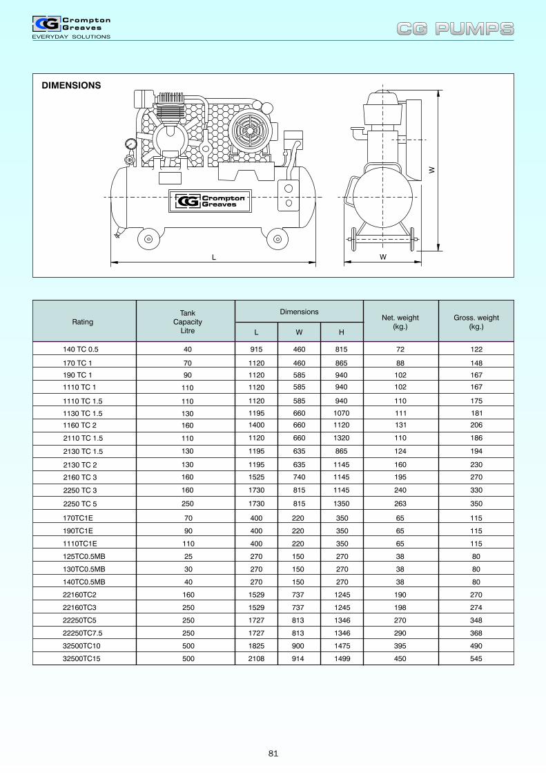
DIMENSIONS
L W
W
170TC1E 70
190TC1E 90 400 220 350 65 115
1110TC1E 110 400 220 350 65 115
125TC0.5MB 25 270 150 270 38 80
130TC0.5MB 30 270 150 270 38 80
140TC0.5MB 40 270 150 270 38 80
22160TC2 160 1529 737 1245 190 270
22160TC3 250 1529 737 1245 198 274
22250TC5 250 1727 813 1346 270 348
22250TC7.5 250 1727 813 1346 290 368
32500TC10 500 1825 900 1475 395 490
32500TC15 500 2108 914 1499 450 545
400 220 350 65 115
72
88
102
102
110
111
131
110
124
160
195
240
122
148
167
167
175
181
206
186
194
230
270
330
915
1120
1120
1120
1120
1195
1400
1120
1195
1195
1525
1730
460
460
585
585
585
660
660
660
635
635
740
815
815
865
940
940
940
1070
1120
1320
865
1145
1145
1145
Rating
140 TC 0.5
170 TC 1
190 TC 1
1110 TC 1
1110 TC 1.5
1130 TC 1.5
1160 TC 2
2110 TC 1.5
2130 TC 1.5
2130 TC 2
2160 TC 3
2250 TC 3
40
70
90
110
110
130
160
110
130
130
160
160
TankCapacity
Litre
Dimensions
L
Net. weight(kg.)
W H
Gross. weight(kg.)
263 3502250 TC 5 250 1730 815 1350
CG PUMPSCG PUMPS
81
REGISTERED OFFICE WORKSCG House, 6th Floor, Dr Annie Besant road, Pumps DivisionWorli, Mumbai - 400 030. A-28, MIDC, Ahmednagar - 414 111.Tel. (022) 24237777 Tel. (0141) 5606500Fax (022) 24237788 Fax (0141) 5606550
BRANCH OFFICES & SERVICE CENTRE
BRANCH DETAILS SERVICE CENTRE DETAILS
NORTHERN REGIONREGIONAL OFFICE - DELHI Vandana building, 11 Tolstoy Marg, Vandana building, 11 Tolstoy Marg,
New Delhi - 110001 New Delhi - 110001Tel. (011) 30416300, 23352161/62 Tel. (011) 30416308, 30416304, 30416311Fax (011) 23324360, 23352134, 23731475 Fax (011) 23730920e mail. [email protected]
JAIPUR Church Road, PO box 173, Church Road, P.O. Box 173, Jaipur - 302001 Jaipur - 302001Tel. (0141) 3018800-29, 2376919 Tel. (0141) 2365604Fax (0141) 2365371 Fax (0141) 2365371e mail. [email protected]
JALANDHAR 416-417, 3rd Floor, prestige chambers, Villege Khajuria, Outside Jalandhar Octroi,G.T. Road, Jalandhar - 144001. Post, Phagwara Road, G.T. Road, Tel. (0181) 3240990-93 Dist. Kapurthala, Jalandhar - 144002Fax (0181) 23324360, 23352134 Tel. (0181) 2632199, 2632187e mail. [email protected] Plot no. 281, Industrial area, Phase 2,
Chandigarh - 160002.Tel. (0172) 2659764Fax (0172) 2657402
LUCKNOW Saran Chambers II, 3rd Floor, 5 Park Road, B-2, Transport Nagar, Lucknow - 226001Lucknow - 226012.Tel. (0522) 3018852/55 Tel. (0522) 2432345, 2433132Fax (0522) 2237009 e mail. [email protected]
EASTERN REGIONREGIONAL OFFICE - KOLKATA 50, Chowringhee Road, 21, R.N. Mukherjee Road, kolkata - 700071.
Kolkata - 700001Tel. (033) 22829681-85 Tel. (033) 22489160, 22488911Fax (033) 22829942, 22824818 Fax (033) 22489737e mail. [email protected]
BHUBNESHWAR Janpath Tower, 3rd Floor, Janpath Tower, 3rd Floor, Ashok nagar Unit II, Bhubneshwar - 751009 Ashok nagar Unit II, Bhubneshwar - 751009Tel. (0674) 2531128, 2531429, 2531277 Tel. (0674) 2531128, 2531429, 2531277Fax (0674) 2533521 Fax (0674) 2533521e mail. [email protected]
PATNA Vishwasadan, Behind Jeevan Deep Bldg,East of Narmada Apartment, Exhibition Road, Patna - 800001.(0612) 2239405
CG PUMPSCG PUMPS
82
BRANCH DETAILS SERVICE CENTRE DETAILS
WESTERN REGION
REGIONAL OFFICE - MUMBAI Kanjurmarg (East), Kanjurmarg (East), Mumbai - 400 042 Mumbai - 400 042Tel. (022) 67558000, 67558591 Tel. (022) 67558000, 67558590Fax (022) 67558669 Fax (022) 67558669e mail. [email protected]
AHMEDABAD 909-916, Sakar II, Near Ellis bridge, Godown No. 799-Cadilla Estate,Ahmedabad - 380006 Opp. Hotel Alfa, N. H. No. 8Tel. (079) 40012000, 40012277 Aslali, Dist. AhmedabadFax (079) 40012222 Tel. : (079) 261408e mail. [email protected] Fax : (079) 261422
INDORE 103-B, Apollo Trade Centre, 2B Rajgarh Kothi, 103-B, Apollo Trade Centre, 2B Rajgarh Kothi,Mumbai-Agra Road, Indore - 452001 Mumbai-Agra Road, Indore - 452001Tel. (0731) 2498269, 2498271, 2498276 Tel. (0731) 2498269, 2498271, 2498276Fax (0731) 5065621 Fax (0731) 5065621, 5067146e mail. [email protected]
PUNE Premium Point building, 4th Floor, Premium Point building, 4th Floor,Opp modern high school, J M Road, Opp modern high school, J M Road,Shivajinagar, Pune - 411005. Shivajinagar, Pune - 411005.Tel. (020) 25534675-77 Tel. (020) 25534675-77Fax (020) 25534684 Fax (020) 25534684e mail. [email protected]
NAGPUR 3, West High Court Road, Lal Bahadur 3, West High Court Road, Lal BahadurShahshtri Chowk, Dharampeth, Shahshtri Chowk, Dharampeth, Nagpur - 440010 Nagpur - 440010Tel. 0712) 2531271, 2560870, 2560871 Tel. 0712) 2531271, 2560870, 2560871Fax (0712) 2537196 Fax (0712) 2537196e mail. [email protected]
SOUTHERN REGIONREGIONAL OFFICE - CHENNAI Crompton House - 3, Dr. MGR Salai Crompton House - 3, Dr. MGR Salai
(Kodambakkam high road), Nungambakkam, (Kodambakkam high road), Nungambakkam,Chennai - 600034. Chennai - 600034.Tel. (044) 42247500, 28257375 Tel. (044) 42247500, 42247595Fax (044) 28231973, 28234112 Fax (044) 28231973, 28234112e mail. [email protected] 658-664, Rajalakshmi Plaza, 100 ft Road,
Gandhipuram, Coimbatore - 641012.Tel. (0422) 2526453, 2521829/30Fax (0422) 2525334
BANGALORE Janardhana Towers, 1st Floor, SS Agencies, No. 20, New Timber Yard562/640 Bannerghetta Road, Bilekahalli, Layout, Mysore Road, Bangalore - 560026.Bangalore - 560076. Tel. (080) 26755727Tel. (080) 41391908, 41391909 Fax (080) 26755723Fax (080) 41391900e mail. [email protected]
COCHIN Cherupushpam Building, 5th Floor, 35/1872 A, South Janata Road, 300-6, Shanmugham Road, Ernakulam, Palarivottam, Cochin - 682025Cochin - 682031 Tel. (0484) 2338102Tel. (0484) 2370860-63, 2360240, 2382340 Fax (0484) 2338856Fax (0484) 2373738e mail. [email protected]
SECUNDERABAD Minerva Complex, 4th Floor, 13/2, Industrial Area, Rasalpura, 94, Sarojini devi road, Secunderabad - 500003. Secunderabad - 500003Tel. (040) 27905938, 55269001 Tel. (040) 40002300, 40002307Fax (040) 40002340e mail. [email protected]
CG PUMPSCG PUMPS
83

CG PUMPSCG PUMPS

CG PUMPSCG PUMPS
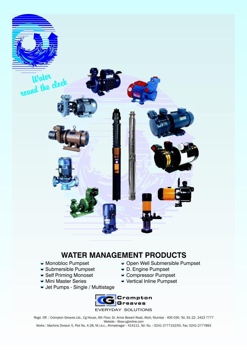
Monobloc PumpsetSubmersible PumpsetSelf Priming MonosetMini Master SeriesJet Pumps - Single / Multistage
Open Well Submersible PumpsetD. Engine PumpsetCompressor PumpsetVertical Inline Pumpset
WATER MANAGEMENT PRODUCTS
Regd. Off. : Crompton Greaves Ltd., Cg House, 6th Floor, Dr. Annie Besant Road, Worli, Mumbai - 400 030. Tel. 91-22- 2423 7777Website : Www.cglonline.com
Works : Machine Division 5, Plot No. A-28, M.i.d.c., Ahmednagar - 414111, Tel: No. : 0241-2777152/55. Fax: 0241-2777893
Water
n rou d the clock
Recommended