Chapter 2 Software Processes Slide 1
Chapter 2
Software Processes
Chapter 2 Software Processes Slide 2
Topics covered
Software processes and process models Generic models:
• Waterfall• incremental development• Reuse-oriented software engineering
Basic process activities:• Specification• Development• Validation (and Verification)• Evolution
(cont'd)
Chapter 2 Software Processes Slide 3
Topics covered (cont’d)
Coping with change
Software prototyping:• Uses of prototypes• Classifying prototypes• User Interface prototyping
(Mills’) Incremental Delivery (cf. incremental development)
Boehm’s spiral model
The Rational Unified Process (an example of a modern software development process/method)
Chapter 2 Software Processes Slide 4
Software processes and process models
Chapter 2 Software Processes Slide 5
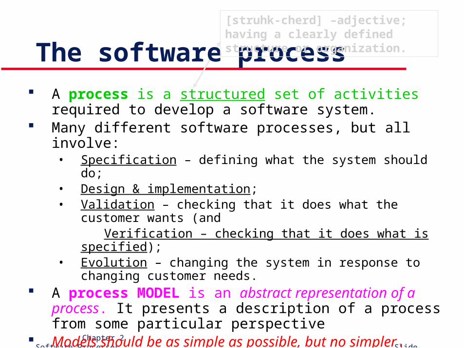
The software process A process is a structured set of activities required to develop
a software system. Many different software processes, but all involve:
• Specification – defining what the system should do;• Design & implementation;• Validation – checking that it does what the customer wants (and
Verification – checking that it does what is specified);• Evolution – changing the system in response to changing
customer needs. A process MODEL is an abstract representation of a
process. It presents a description of a process from some particular perspective
Models should be as simple as possible, but no simpler.– A. Einstein
[struhk-cherd] –adjective; having a clearly defined structure or organization.
Chapter 2 Software Processes Slide 6
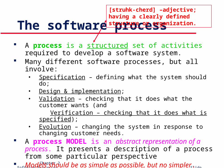
The software process A process is a structured set of activities required to develop
a software system. Many different software processes, but all involve:
• Specification – defining what the system should do;• Design & implementation;• Validation – checking that it does what the customer wants (and
Verification – checking that it does what is specified);• Evolution – changing the system in response to changing
customer needs. A process MODEL is an abstract representation of a
process. It presents a description of a process from some particular perspective
Models should be as simple as possible, but no simpler.– A. Einstein
[struhk-cherd] –adjective; having a clearly defined structure or organization.
Chapter 2 Software Processes Slide 7
Plan-driven and agile processes
Plan-driven processes: all of the process activities are planned in advance and progress is measured against this plan.
Agile processes: planning is incremental and it is easier to change the process to reflect changing customer requirements.
In practice, most practical processes include elements of both plan-driven and agile approaches.
There are no right or wrong software processes!
Chapter 2 Software Processes Slide 8
Generic models
Chapter 2 Software Processes Slide 9
Generic software process models
The Waterfall Model – plan-driven model; separate and distinct phases of specification and development. not iterative
incremental development – specification, development, & validation are interleaved; may be plan-driven or agile.
Reuse-Based Development – e.g., “component-based SE”: the system is assembled from existing components; may be plan-driven or agile.
-----------------------------In practice, most large systems are developed using a pro-cess that incorporates elements from all of these models.
(And, at no additional cost: Boehm’s Spiral Model.)
Chapter 2 Software Processes Slide 10
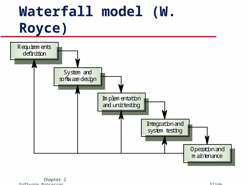
Waterfall model (W. Royce)Requirements
definition
System andsoftware design
Implementationand unit testing
Integration andsystem testing
Operation andmaintenance
Chapter 2 Software Processes Slide 11
Waterfall model (cont’d)
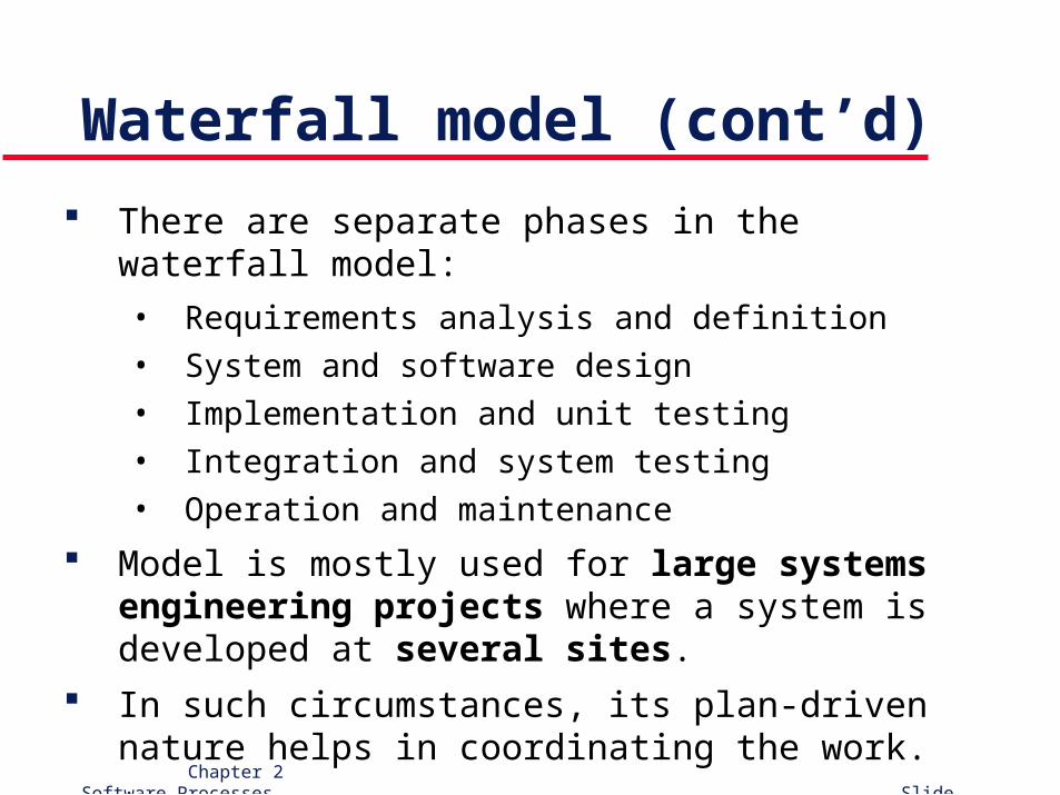
There are separate phases in the waterfall model:
• Requirements analysis and definition
• System and software design
• Implementation and unit testing
• Integration and system testing
• Operation and maintenance
Model is mostly used for large systems engineering projects where a system is developed at several sites.
In such circumstances, its plan-driven nature helps in coordinating the work.
Chapter 2 Software Processes Slide 12
Waterfall model problems
Inflexible partitioning of the project into distinct stages makes it difficult to respond to changing customer requirements.• Thus, more appropriate when requirements are well-
understood to begin with.• This applies to relatively few systems.
--------------------------------------------- In general, the drawback of the waterfall model is the
difficulty of accommodating change after the pro-cess is underway.
Chapter 2 Software Processes Slide 13
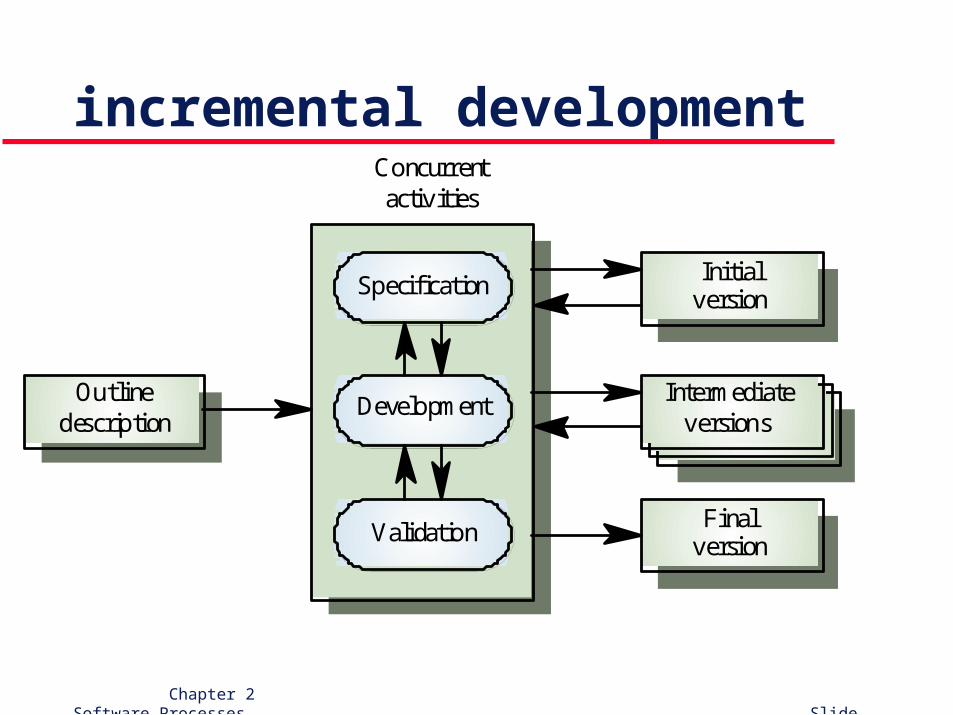
incremental development
Validation Finalversion
DevelopmentIntermediate
versions
SpecificationInitial
version
Outlinedescription
Concurrentactivities
Chapter 2 Software Processes Slide 14
incremental development benefits
Reduces cost of accommodating changing customer requirements - amount of analysis and documentation that has to be re-done is much less than is required with the waterfall model.
Easier to get customer feedback - customers can comment on demonstrations of the software and see how much has been implemented.
More rapid delivery & deployment of useful software to the customer is possible - customers may be able to use and gain value from the software earlier than is possible with a waterfall process.
Chapter 2 Software Processes Slide 15
incremental development problems
Lack of process visibility - lack of document deliverables to measure progress. If systems are developed quickly, it is not cost-effective to produce documents that reflect every version of the system.
System structure tends to degrade as new increments are added - unless time and money is spent on refactoring to improve the software, regular change tends to corrupt its structure. Incorporating further software changes becomes increasingly difficult and costly.
Chapter 2 Software Processes Slide 16
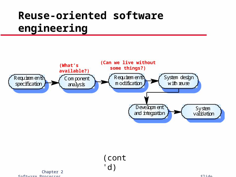
Reuse-oriented software engineering
Based on systematic (as opposed to serendipitous) reuse - systems are integrated from existing components or COTS (Commercial-Off-The-Shelf) systems.
Primary Reuse-Affected Process stages:
• Component analysis (What’s available?)• Requirements modification (Can we live without some things?)• System design with reuse• Development and integration
“Reuse” is now the standard approach for building many types of business systems.
(cont'd)
Chapter 2 Software Processes Slide 17
Reuse-oriented software engineering
Requirementsspecification
Componentanalysis
Developmentand integration
System designwith reuse
Requirementsmodification
Systemvalidation
(What’s available?)
(cont'd)
(Can we live withoutsome things?)
Chapter 2 Software Processes Slide 18
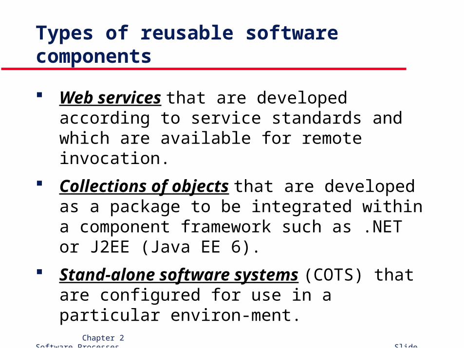
Types of reusable software components
Web services that are developed according to service standards and which are available for remote invocation.
Collections of objects that are developed as a package to be integrated within a component framework such as .NET or J2EE (Java EE 6).
Stand-alone software systems (COTS) that are configured for use in a particular environ-ment.
Chapter 2 Software Processes Slide 19
Basic process activities
Chapter 2 Software Processes Slide 20
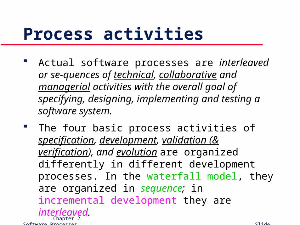
Process activities
Actual software processes are interleaved or se-quences of technical, collaborative and managerial activities with the overall goal of specifying, designing, implementing and testing a software system.
The four basic process activities of specification, development, validation (& verification), and evolution are organized differently in different development processes. In the waterfall model, they are organized in sequence; in incremental development they are interleaved.
Chapter 2 Software Processes Slide 21
Software specification / RE
The process of establishing what services are required and the constraints on the system’s operation and development.
Requirements Engineering (RE) process:• Feasibility (technical and otherwise) study• Requirements elicitation and analysis• Requirements specification (documentation)• Requirements validation
(cont'd)
Chapter 2 Software Processes Slide 22
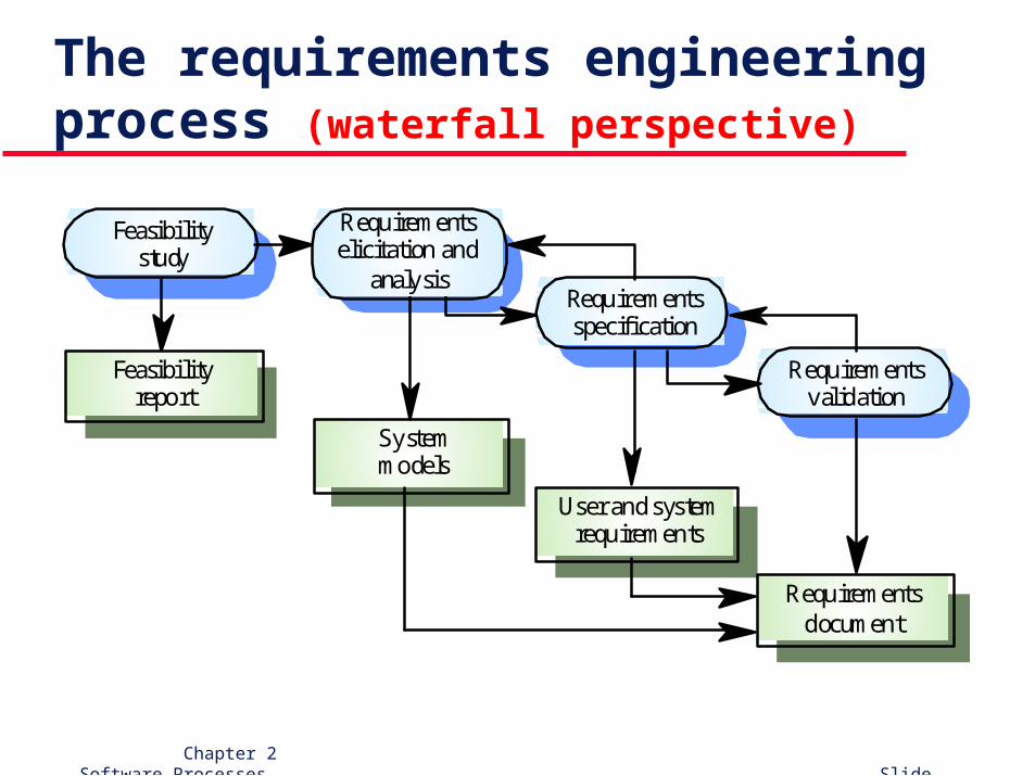
The requirements engineering process (waterfall perspective)
Feasibilitystudy
Requirementselicitation and
analysisRequirementsspecification
Requirementsvalidation
Feasibilityreport
Systemmodels
User and systemrequirements
Requirementsdocument
Chapter 2 Software Processes Slide 23
Software design and implementation
The process of producing an executable system based on the specification (waterfall perspective)• Software design – design a software structure that realizes
the specification.
• Implementation – translate this structure into an executable program.
Note: the activities of specification, design, and implementation are closely related and may be interleaved (as with incremental development).
Chapter 2 Software Processes Slide 24
Design activities
Architectural design: identify overall structure of system, principal components (sometimes called sub-systems or modules), their relationships, and how they are distributed.
Interface design: define the interfaces between system components.
Component design: design how each system component will operate.
Database (data structure) design: design system data structures and how these are to be represented in a database.
Chapter 2 Software Processes Slide 25
Software verification & validation
Verification and Validation (V&V) determines whether or not a system (1) conforms to its specification and (2) meets the requirements of the customer.
Involves (human-based) checking processes (e.g., inspections/reviews, formal verification) and (machine-based) program testing.
Program testing is the most commonly used V&V activity and involves executing program elements with test cases that are derived from analyzing specifications and/or program logic.
Chapter 2 Software Processes Slide 26
Testing stages Development or component testing
• Individual components are tested independently;
• “Components” may be functions or objects or coherent groupings of these entities.
System testing
• Testing of the system as a whole. Testing of emergent properties is particularly important.
Acceptance testing
• Testing with customer data to check that the system meets the customer’s needs/desires.
Chapter 2 Software Processes Slide 27
Software evolution (“maintenance”)
Software is inherently flexible and subject to change.
As requirements change through changing business/environmental circumstances, the software must also evolve and change.
The distinction between development and evolution has become increasingly irrelevant as fewer and fewer systems are completely new.
(cont'd)
Chapter 2 Software Processes Slide 28
Software evolution (“maintenance”)
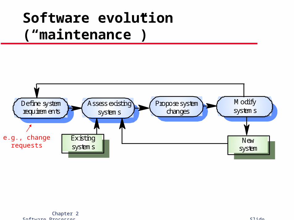
Assess existingsystems
Define systemrequirements
Propose systemchanges
Modifysystems
Newsystem
Existingsystems
e.g., change requests
Chapter 2 Software Processes Slide 29
Coping with change
Chapter 2 Software Processes Slide 30
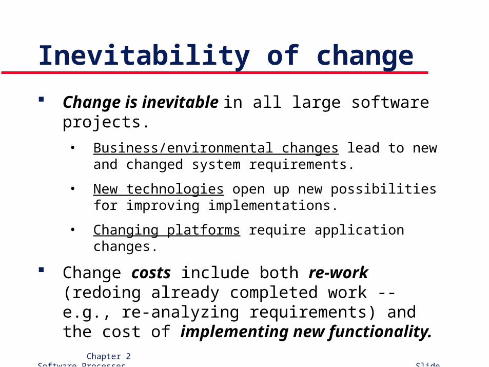
Inevitability of change
Change is inevitable in all large software projects.
• Business/environmental changes lead to new and changed system requirements.
• New technologies open up new possibilities for improving implementations.
• Changing platforms require application changes.
Change costs include both re-work (redoing already completed work -- e.g., re-analyzing requirements) and the cost of implementing new functionality.
Chapter 2 Software Processes Slide 31
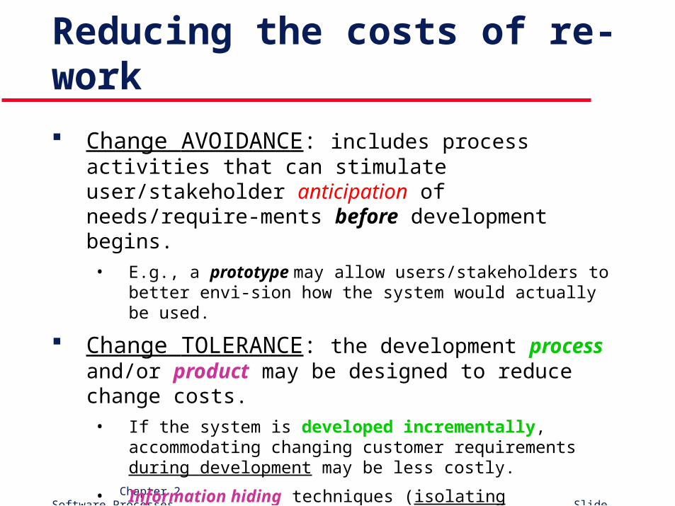
Reducing the costs of re-work
Change AVOIDANCE: includes process activities that can stimulate user/stakeholder anticipation of needs/require-ments before development begins. • E.g., a prototype may allow users/stakeholders to better envi-
sion how the system would actually be used.
Change TOLERANCE: the development process and/or product may be designed to reduce change costs.• If the system is developed incrementally, accommodating
changing customer requirements during development may be less costly.
• Information hiding techniques (isolating potentially changeable design decisions) may be employed in product design to reduce costs after development.
Chapter 2 Software Processes Slide 32
Software prototyping
Chapter 2 Software Processes Slide 33
What is prototyping?
An iterative process emphasizing:
• Rapid development
• Concreteness and evaluative use (a “real system” is developed and presented to real users for hands-on evaluation)
• Consideration of alternatives
• Feedback
• Modification
Chapter 2 Software Processes Slide 34
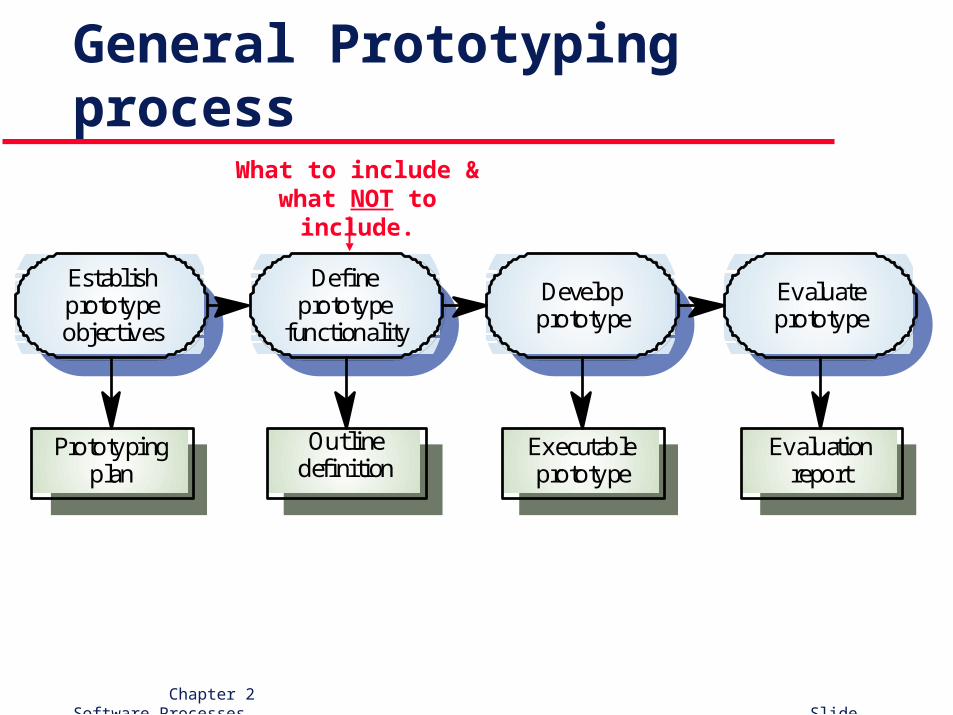
General Prototyping process
Establishprototypeobjectives
Defineprototype
functionality
Developprototype
Evaluateprototype
Prototypingplan
Outlinedefinition
Executableprototype
Evaluationreport
What to include & what NOT to include.
Chapter 2 Software Processes Slide 35
Uses of prototypes
Principal use is to help customers and developers better understand system requirements. ( change AVOIDANCE)• Experimentation stimulates anticipation of how a
system could/may actually be used.• Attempting to use functions together to
accomplish some (higher-level) task often reveals subtle requirements problems.
(cont’d)
Chapter 2 Software Processes Slide 36
Uses of prototypes (cont’d)
Other potential uses:
1. Evaluating proposed solutions for feasibility (=“Experimental Prototyping”)
2. Develop and evaluate User Interface designs3. “Back-to-back testing”4. Training users before system delivery
Prototyping is most often undertaken as a risk reduction activity.
Chapter 2 Software Processes Slide 37
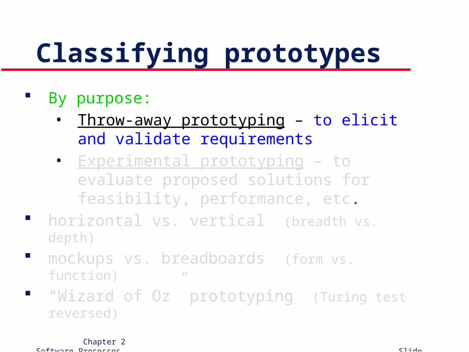
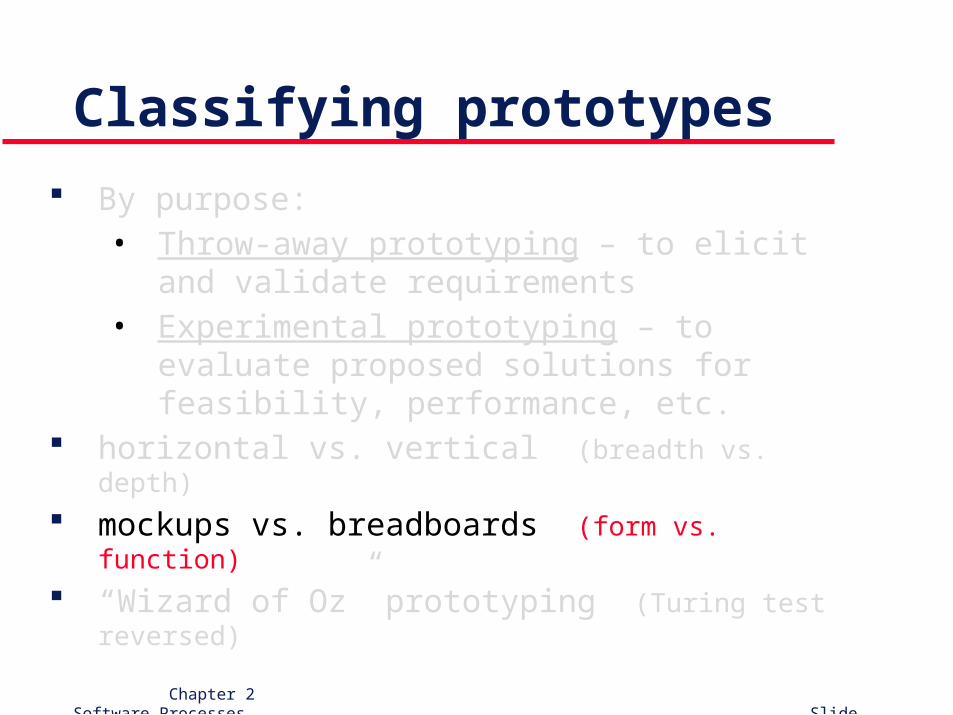
Classifying prototypes
By purpose:• Throw-away prototyping – to elicit and validate
requirements• Experimental prototyping – to evaluate proposed
solutions for feasibility, performance, etc. horizontal vs. vertical (breadth vs. depth)
mockups vs. breadboards (form vs. function)
“Wizard of Oz” prototyping (Turing test reversed)
Chapter 2 Software Processes Slide 38
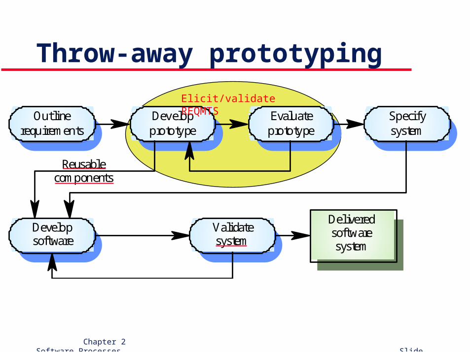
Throw-away prototyping
Outlinerequirements
Developprototype
Evaluateprototype
Specifysystem
Developsoftware
Validatesystem
Deliveredsoftwaresystem
Reusablecomponents
Elicit/validate REQMTS
Chapter 2 Software Processes Slide 39
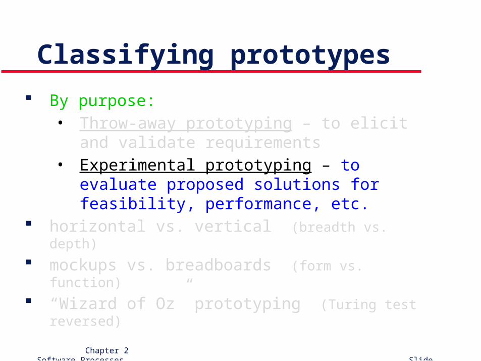
Classifying prototypes
By purpose:• Throw-away prototyping – to elicit and validate
requirements• Experimental prototyping – to evaluate proposed
solutions for feasibility, performance, etc. horizontal vs. vertical (breadth vs. depth)
mockups vs. breadboards (form vs. function)
“Wizard of Oz” prototyping (Turing test reversed)
Chapter 2 Software Processes Slide 40
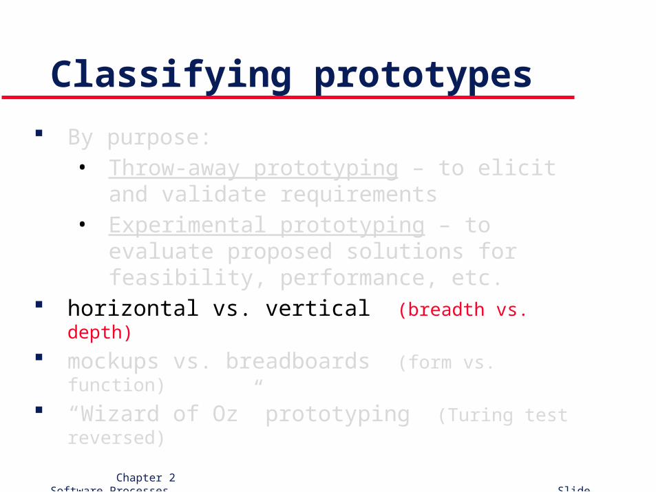
Classifying prototypes
By purpose:• Throw-away prototyping – to elicit and validate
requirements• Experimental prototyping – to evaluate proposed
solutions for feasibility, performance, etc. horizontal vs. vertical (breadth vs. depth)
mockups vs. breadboards (form vs. function)
“Wizard of Oz” prototyping (Turing test reversed)
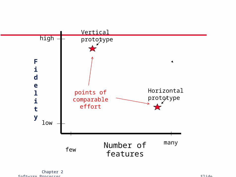
Fidelity
Number of features few many
low
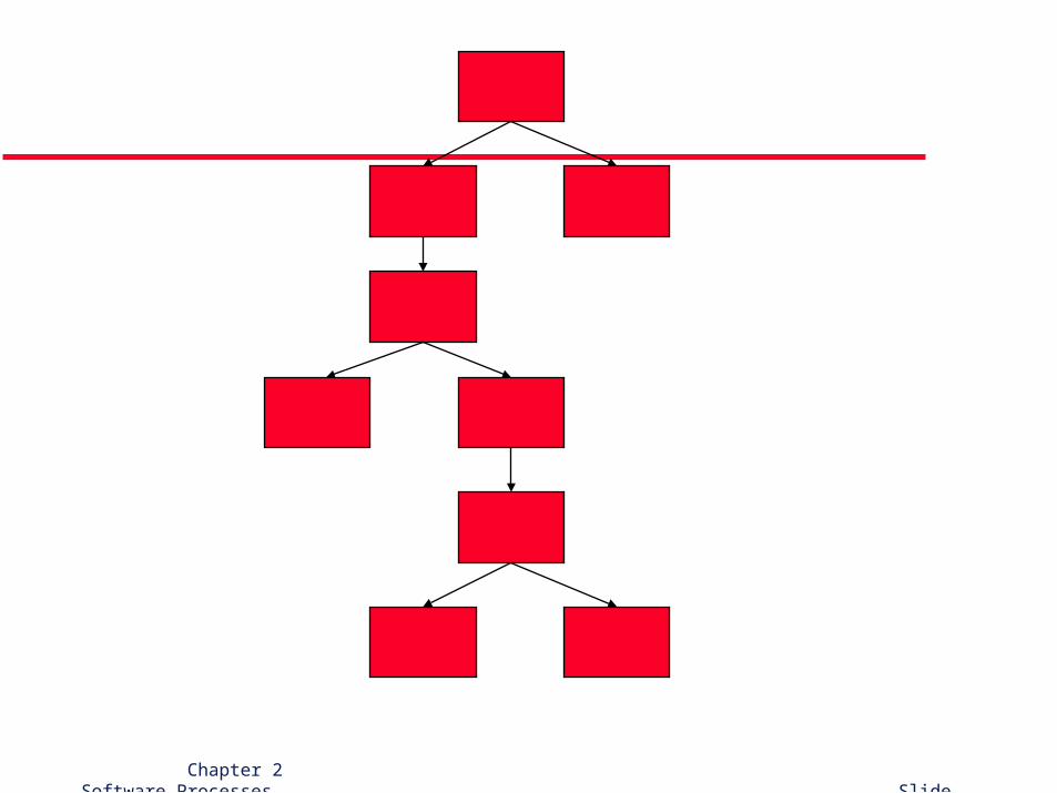
highVertical prototype
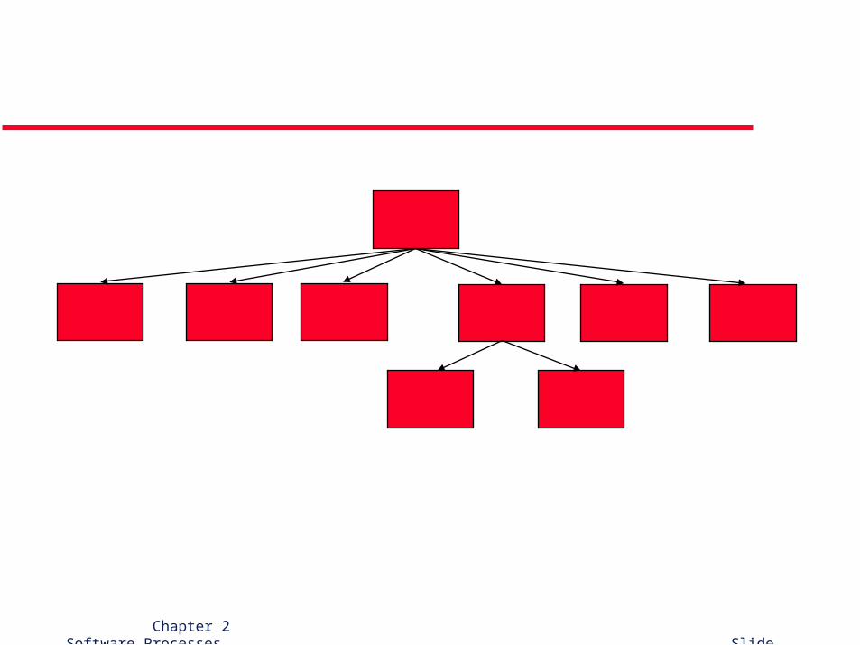
Horizontal prototypepoints of comparable effort
Chapter 2 Software Processes Slide 44
Classifying prototypes
By purpose:• Throw-away prototyping – to elicit and validate
requirements• Experimental prototyping – to evaluate proposed
solutions for feasibility, performance, etc. horizontal vs. vertical (breadth vs. depth)
mockups vs. breadboards (form vs. function)
“Wizard of Oz” prototyping (Turing test reversed)
Chapter 2 Software Processes Slide 45
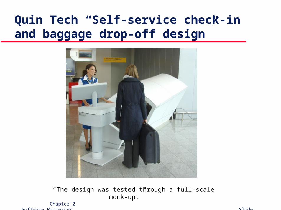
Quin Tech “Self-service check-in and baggage drop-off design”
“The design was tested through a full-scale mock-up.”
Chapter 2 Software Processes Slide 46
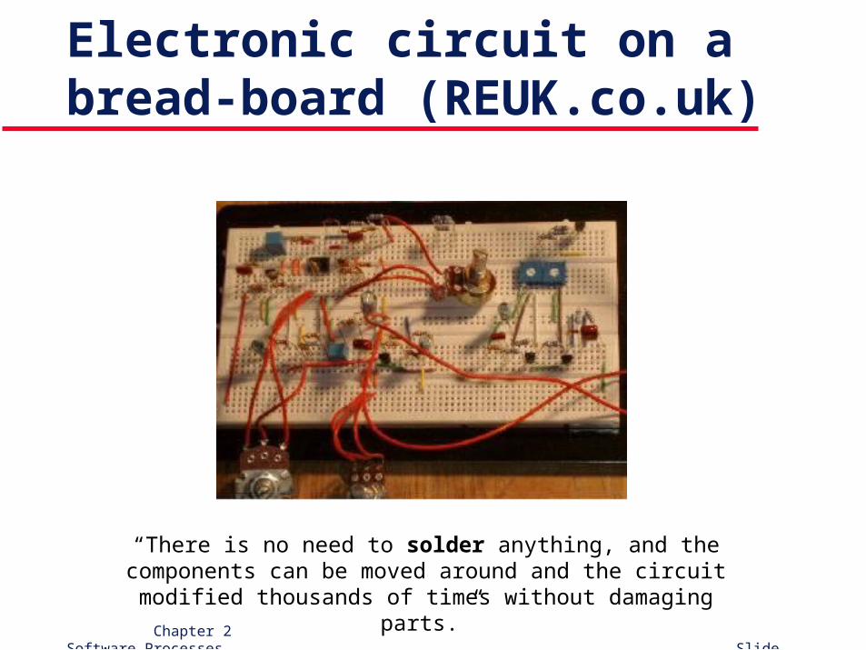
Electronic circuit on a bread-board (REUK.co.uk)
“There is no need to solder anything, and the components can be moved around and the circuit modified thousands of times without damaging parts.”
Chapter 2 Software Processes Slide 47
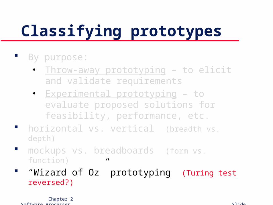
Classifying prototypes
By purpose:• Throw-away prototyping – to elicit and validate
requirements• Experimental prototyping – to evaluate proposed
solutions for feasibility, performance, etc. horizontal vs. vertical (breadth vs. depth)
mockups vs. breadboards (form vs. function)
“Wizard of Oz” prototyping (Turing test reversed?)
Chapter 2 Software Processes Slide 48
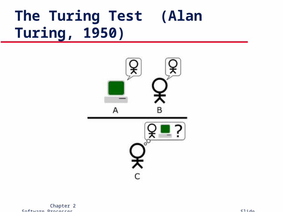
The Turing Test (Alan Turing, 1950)
Chapter 2 Software Processes Slide 49
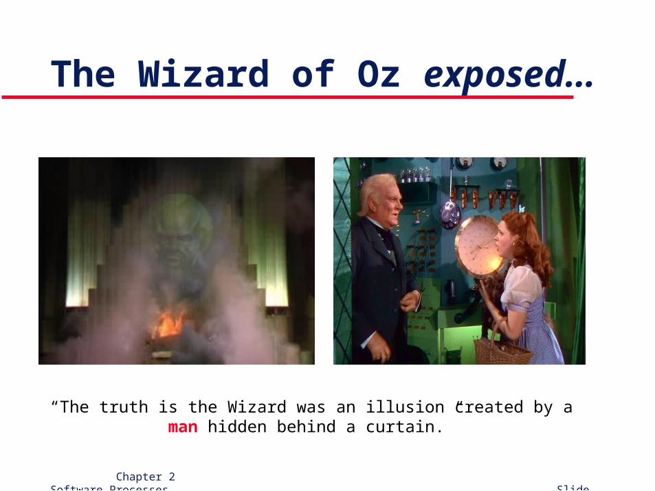
The Wizard of Oz exposed…
“The truth is the Wizard was an illusion created by a man hidden behind a curtain.”
Chapter 2 Software Processes Slide 50
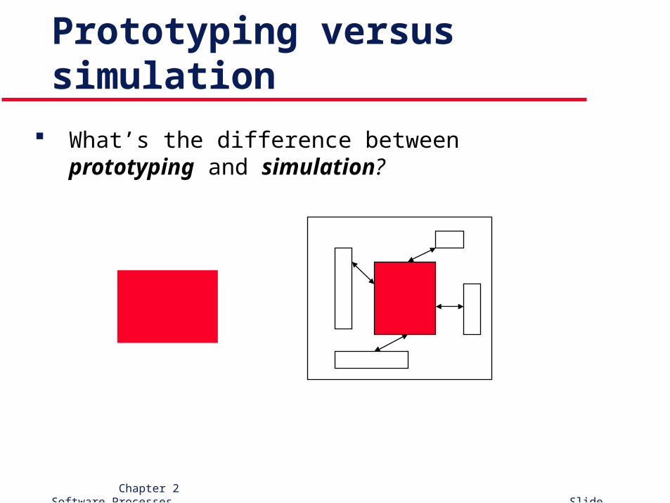
Prototyping versus simulation
What’s the difference between prototyping and simulation?
Chapter 2 Software Processes Slide 51
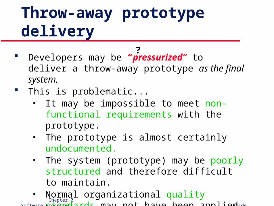
Throw-away prototype delivery
Developers may be “pressurized” to deliver a throw-away prototype as the final system.
This is problematic...• It may be impossible to meet non-functional
requirements with the prototype.• The prototype is almost certainly undocumented.• The system (prototype) may be poorly structured
and therefore difficult to maintain.• Normal organizational quality standards may not
have been applied.
?
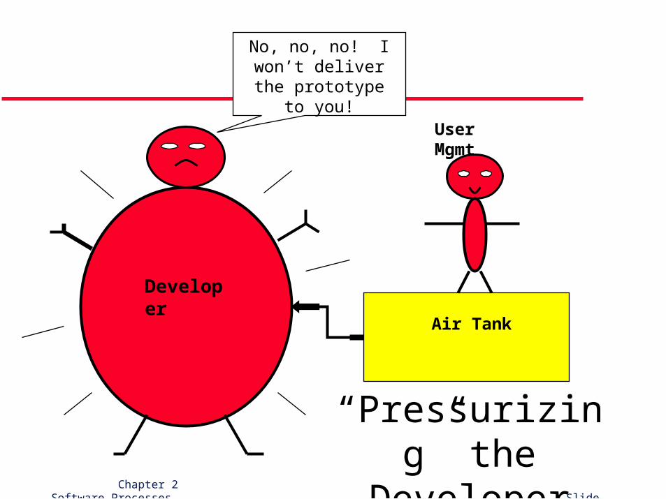
Air Tank
Developer
User Mgmt
No, no, no! I won’t deliver the prototype to
you!
“Pressurizing” the Developer
Chapter 2 Software Processes Slide 53
Implementation techniques
Various techniques may be used to implement prototypes: • Dynamic, high-level languages (typeless, interpretive)
• Database programming (RAD / 4GLs)
• Component and application assembly These are NOT mutually exclusive – they are
often used together. Visual programming is also an inherent part of
most prototype development systems.
Chapter 2 Software Processes Slide 54
User interface prototyping
User interface development consumes an increasing part of overall system develop-ment costs.
It is usually impossible to pre-specify the look and feel of a complex user interface in an effective way. Thus, prototyping is essential.
(cont’d)
Chapter 2 Software Processes Slide 55
User interface prototyping (cont’d)
Aim is to allow users to gain direct experi-ence with the interface.
Without this, it is almost impossible to judge usability.
Often a two-stage process:
• paper prototypes are developed initially,
• followed by a series of increasingly sophis-ticated automated prototypes.
Chapter 2 Software Processes Slide 56
Paper prototyping
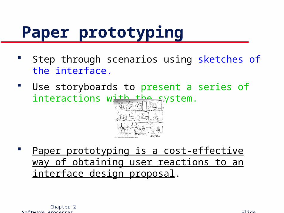
Step through scenarios using sketches of the interface.
Use storyboards to present a series of interactions with the system.
Paper prototyping is a cost-effective way of obtaining user reactions to an interface design proposal.
Chapter 2 Software Processes Slide 57
(Mills’) Incremental Delivery
(not to be confused with the “incremental development”
generic model)
Chapter 2 Software Processes Slide 58
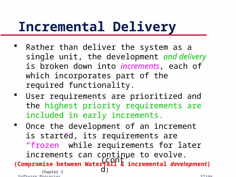
Incremental Delivery Rather than deliver the system as a single unit, the
development and delivery is broken down into increments, each of which incorporates part of the required functionality.
User requirements are prioritized and the highest priority requirements are included in early increments.
Once the development of an increment is started, its requirements are “frozen” while requirements for later increments can continue to evolve.(Compromise between Waterfall & incremental development)
(cont’d)
Chapter 2 Software Processes Slide 59
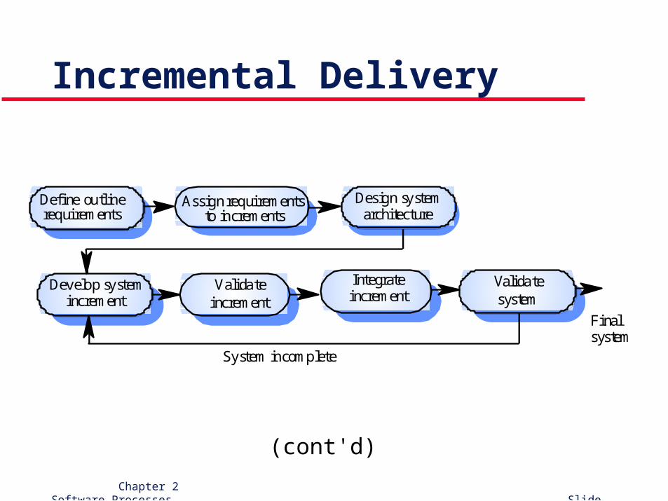
Incremental Delivery
Valida teincrement
Develop systemincrement
Design systemarchitecture
Integrateincrement
Valida tesystem
Define outline requirements
Assign requirements to increments
System incomplete
Finalsystem
(cont'd)
Chapter 2 Software Processes Slide 60
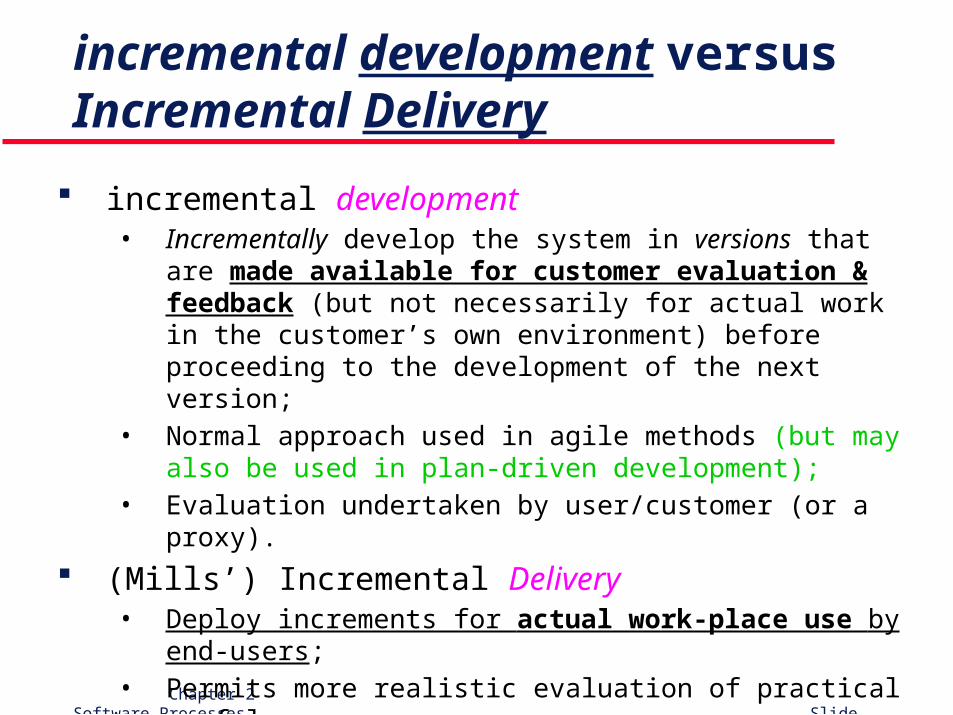
incremental development versus Incremental Delivery
incremental development• Incrementally develop the system in versions that are made
available for customer evaluation & feedback (but not necessarily for actual work in the customer’s own environment) before proceeding to the development of the next version;
• Normal approach used in agile methods (but may also be used in plan-driven development);
• Evaluation undertaken by user/customer (or a proxy).
(Mills’) Incremental Delivery• Deploy increments for actual work-place use by end-users;• Permits more realistic evaluation of practical usefulness;• Difficult to carry out for replacement systems as increments
provide less functionality than the system being replaced.
Chapter 2 Software Processes Slide 61
Advantages of Incremental Delivery
Useful functionality is delivered with each increment, so customers derive value early.
Early increments assist in eliciting requirements for later increments.
Lower risk of overall project failure. The highest priority system services tend to receive
the most testing. (They're subject to more “validation” steps.)
(cont'd)
Chapter 2 Software Processes Slide 62
Potential problems with Incremental Delivery
Requirements may NOT be partitionable into usable, stand-alone increments. (e.g., consider a compiler)
Many systems require a set of basic facilities that are used by different parts of the system. But since requirements are not defined in detail until an increment is to be implemented, it can be hard to identify common facilities that are needed by all increments to be useful.
The essence of an iterative process is that the specification is developed in conjunction with the software. But this conflicts with the procurement model of many organizations, where the complete specification is part of the system development contract (also a problem with incremental development).
Chapter 2 Software Processes Slide 63
Spiral development model
Chapter 2 Software Processes Slide 64
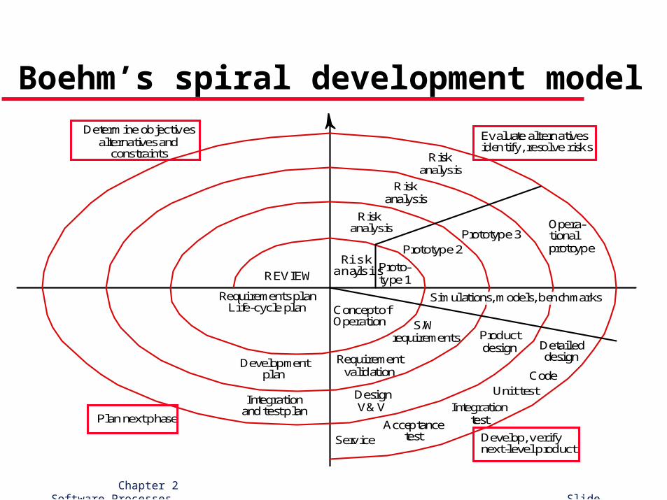
Boehm’s spiral development model
Process is represented as a spiral rather than a sequence of activities.
Each loop in the spiral represents a phase in the process.
No fixed phases such as specification or design – loops in the spiral are chosen depending on what is required.
Explicitly incorporates risk assessment and resolution throughout the process.
(cont'd)
Chapter 2 Software Processes Slide 65
Boehm’s spiral development model
Chapter 2 Software Processes Slide 66
Boehm’s spiral development model
Riskanalysis
Riskanalysis
Riskanalysis
Riskanalysis Proto-
type 1
Prototype 2Prototype 3
Opera-tionalprotoype
Concept ofOperation
Simulations, models, benchmarks
S/Wrequirements
Requirementvalidation
DesignV&V
Productdesign Detailed
design
CodeUnit test
IntegrationtestAcceptance
testService Develop, verifynext-level product
Evaluate alternativesidentify, resolve risks
Determine objectivesalternatives and
constraints
Plan next phase
Integrationand test plan
Developmentplan
Requirements planLife-cycle plan
REVIEW
Chapter 2 Software Processes Slide 67
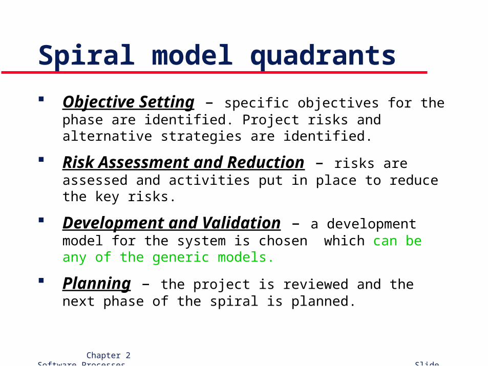
Spiral model quadrants
Objective Setting – specific objectives for the phase are identified. Project risks and alternative strategies are identified.
Risk Assessment and Reduction – risks are assessed and activities put in place to reduce the key risks.
Development and Validation – a development model for the system is chosen which can be any of the generic models.
Planning – the project is reviewed and the next phase of the spiral is planned.
Chapter 2 Software Processes Slide 68
Spiral model usage
The model has been very influential in helping people think about iteration in software processes and introducing the risk-driven approach to development.
In practice, however, the model is rarely used as published for practical software develop-ment.
Chapter 2 Software Processes Slide 69
RUP
Chapter 2 Software Processes Slide 70
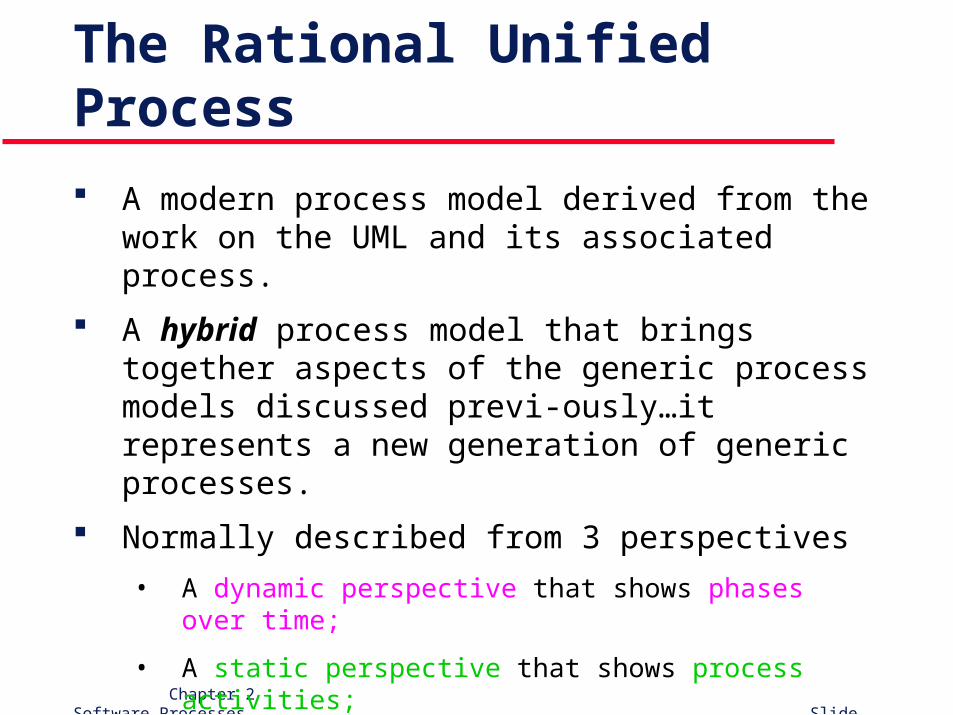
The Rational Unified Process
A modern process model derived from the work on the UML and its associated process.
A hybrid process model that brings together aspects of the generic process models discussed previ-ously…it represents a new generation of generic processes.
Normally described from 3 perspectives
• A dynamic perspective that shows phases over time;
• A static perspective that shows process activities;
• A practice perspective that suggests good practices.
Chapter 2 Software Processes Slide 71
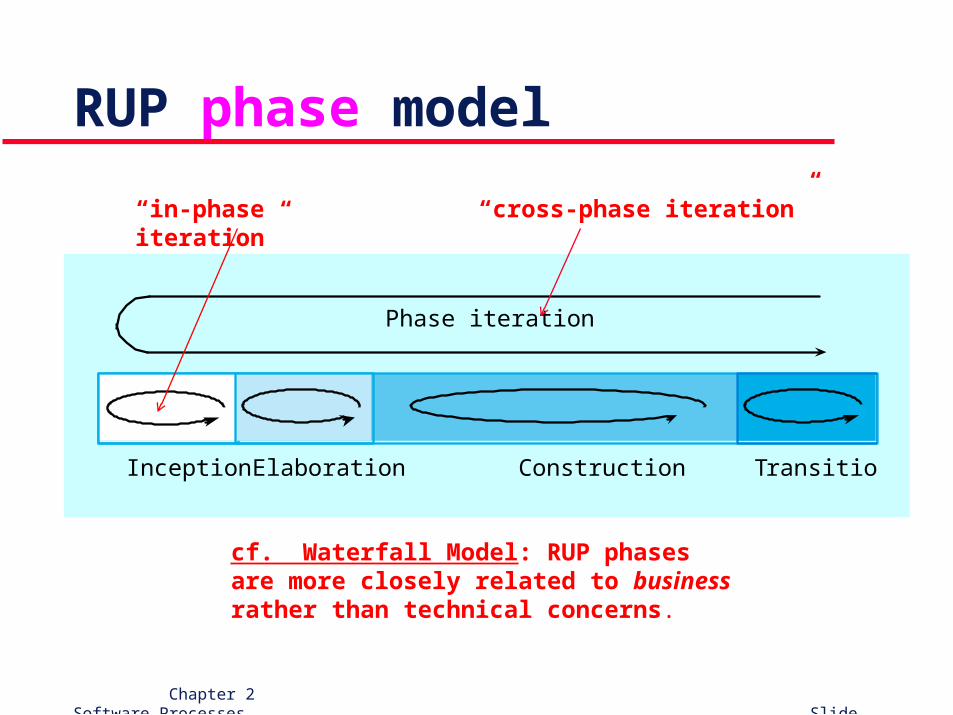
RUP phase model
Phase iteration
Inception Elaboration Construction Transition
cf. Waterfall Model: RUP phases are more closely related to business rather than technical concerns.
“in-phase iteration” “cross-phase iteration”
Chapter 2 Software Processes Slide 72
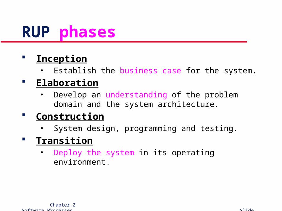
RUP phases
Inception• Establish the business case for the system.
Elaboration• Develop an understanding of the problem domain and the
system architecture.
Construction• System design, programming and testing.
Transition• Deploy the system in its operating environment.
Chapter 2 Software Processes Slide 73
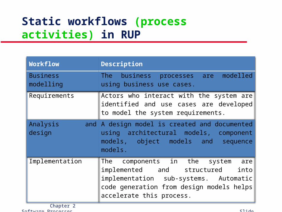
Static workflows (process activities) in RUP
Workflow Description
Business modelling The business processes are modelled using business use cases.
Requirements Actors who interact with the system are identified and use cases are developed to model the system requirements.
Analysis and design A design model is created and documented using architectural models, component models, object models and sequence models.
Implementation The components in the system are implemented and structured into implementation sub-systems. Automatic code generation from design models helps accelerate this process.
Chapter 2 Software Processes Slide 74
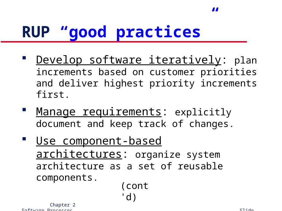
RUP “good practices”
Develop software iteratively: plan increments based on customer priorities and deliver highest priority increments first.
Manage requirements: explicitly document and keep track of changes.
Use component-based architectures: organize system architecture as a set of reusable components.
(cont'd)
Chapter 2 Software Processes Slide 75
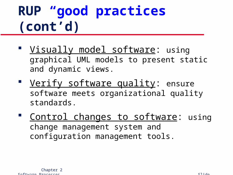
RUP “good practices” (cont’d)
Visually model software: using graphical UML models to present static and dynamic views.
Verify software quality: ensure software meets organizational quality standards.
Control changes to software: using change management system and configuration management tools.
Chapter 2 Software Processes Slide 76
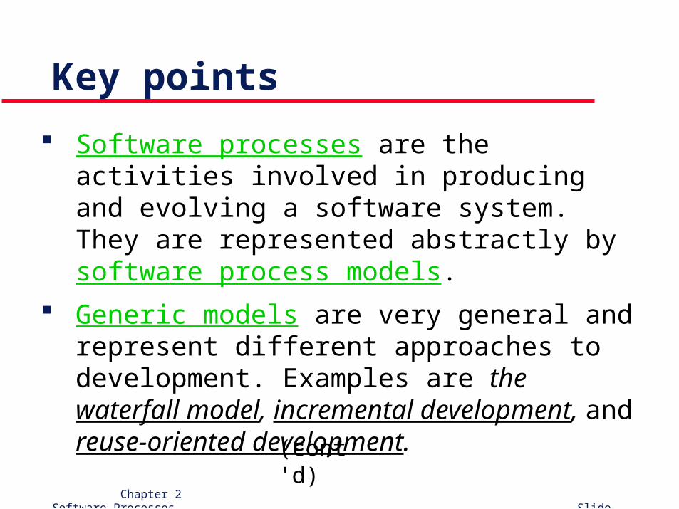
Key points
Software processes are the activities involved in producing and evolving a software system. They are represented abstractly by software process models.
Generic models are very general and represent different approaches to development. Examples are the waterfall model, incremental development, and reuse-oriented development.
(cont'd)
Chapter 2 Software Processes Slide 77
Key points (cont’d)
Requirements engineering is the process of establishing what services are required and the constraints on the system’s operation and development.
Design and implementation processes produce an executable system based on the specification.
V&V involves checking that the system meets its specification and satisfies user needs.
Evolution is concerned with modifying the system after it is placed in use. Software must evolve to remain useful.
(cont'd)
Chapter 2 Software Processes Slide 78
Key points (cont’d)
Processes should include activities to cope with change. This may involve a prototyping phase that helps avoid poor decisions on requirements and design.
Throw-away prototyping is used to explore requirements and design options.
Rapid development of prototypes is essential. This usually requires leaving out functionality or relaxing non-functional constraints.
(cont'd)
Chapter 2 Software Processes Slide 79
Key points (cont’d)
Prototyping may be essential for parts of the system such as the user interface which cannot be effectively pre-specified.
Users must be involved in prototype evaluation. The Rational Unified Process is a modern
generic process model that is organized into phases (inception, elaboration, construction and transition) but separates activities (requirements, analysis and design, etc.) from these phases.
Chapter 2 Software Processes Slide 80
Chapter 2
Software Processes
Recommended