145
CHAPTER 5
PALMPRINT RECOGNITION WITH ENHANCEMENT
5.1 INTRODUCTION
This chapter discusses the application of enhancement technique in
palmprint recognition system. Section 5.2 describes image sharpening
methods. Advanced palmprint recognition system is discussed in Section 5.3.
A palmprint recognition using Symbolic Aggregate approximation (SAX)
features is discussed in Section 5.4. Palmprint recognition using multiple
palmprint features with enhanced palmprint image is given in Section 5.5.
The performance measures are given in Section 5.6. The results are discussed
in Section 5.7 .The performance of the proposed enhancement technique is
compared with the HE technique. Summary of the chapter is given in Section
5.8.
There exist three different categories for palmprint authentication
(Zhang ,2004), divided on the basis of extracted features; (i) line-based
approaches (Han et al 2003, Zhang et al 1999, Han et al 2007 ) (ii)
appearance-based approaches (Lu et al 2003) and (iii) texture-based
approaches .
Line-based methods are based on line matching, line detection,
crease detection, morphological operators etc. Morphological operators (Han
et al 2003) can be used in the feature extraction process in order to obtain the
feature vectors. Datum point invariant and the line feature matching technique
146
(Zhang et al 1999) for the verification process are not appropriate for many
on-line security systems, since it is difficult to extract principal lines from a
low resolution palmprint image. The required recognition rates and
computational efficiency are not fully achieved here. Other issues in the line-
based approaches include the existence of similar line features in many
palmprints, and the thickness and width of the different lines are not taken
into account which is very critical for differentiating palmprints.
Appearance-based approaches are based on the analysis of principal
component and linear discriminate. The original training palmprints are
transformed into small groups of characteristic feature images called
eigenpalms (Lu et al 2003) by means of Karhunen–Loeve (K–L) transform.
But the authentication performance of these eigenpalms is reduced when it is
applied in real time applications.
In texture-based approach, texture features are extracted by means
of gabor filter, discrete cosine transform, ordinal filter, laws mask, discrete
fourier transform, wavelets and so on. Even though the Gabor filter (Kong et
al 2003) gives accurate time-frequency location and robustness against
varying image’s brightness and contrast, it involves high computational cost
and time delay. Difficulty in setting an appropriate filter parameter causes
identification performance to depend much on the training set used for
parameter selection. Orthogonal line ordinal feature (Sun et al 2005) is
currently the best ordinal measure for palmprint representation; still its
theoretical foundation has not been well formulated. Wavelet Energy Feature
technique’s (Wu et al 2002) ability to distinguish palms is very strong because
it can reflect the wavelet energy distribution of the principal lines, wrinkles
and ridges in different directions at varying wavelet decomposition levels.
Disadvantages of this method are its sensitiveness towards noise, the
requirement of high resolution images, implementation cost and time
147
complexity. Fourier transform method (Li et al 2002) is used to ignore the
abundant textural details of a palm, and the extracted features are highly
influenced by the lighting situations. A huge storage of database to store
image templates affects the system’s simplicity.
Personal verification using palmprint and hand geometry biometric
(Kumar et al 2003) does verification by integrating hand geometry features.
Palmprint and hand geometry features are acquired using a digital camera.
These images are aligned and then used to extract palmprint and hand
geometry features. These features are then examined for their individual and
combined performances. The image acquisition setup used in this work is
inherently simple and it does not employ any special illumination, nor does it
use any pegs to cause any inconvenience to the users.
Hierarchical palmprint identification via multiple feature extraction
(You et al 2002) describes a new method to authenticate individuals based on
palmprint identifcation and verification. A texture-based dynamic selection
scheme is used to facilitate the fast search for the best matching of the sample
in the database in a hierarchical fashion. The global texture energy, which is
characterized with high convergence of inner-palm similarities and good
dispersion of inter-palm discrimination, is used to guide the dynamic selection
of a small set of similar candidates from the database at coarse level for
further processing. Multiple palmprint features are used by Nanni and Lumini
(2009) for accurate palmprint recognition.
Combining multiple classifiers by averaging or by multiplying (Tax
et al 2000) combines observations from different sources. Palmprint-based
recognition system using phase difference information (Badrinath et al 2012)
uses histogram equalization for enhancing the contrast of the palmprint
image. Most of the works did not give any attempt to incorporate the
enhancement techniques in biometric palmprint images to achieve
148
performance improvement. In most of the prior systems, the enhancement
stage got little attention. The enhancement of the input image can deeply
affect the output of the system. This work incorporates curvelet and RHE
techniques for enhancement of the palmprint image. Curvelet is used for
removing noise in the palmprint image, and RHE is used for improving the
contrast of the palmprint image. Applying curvelet and RHE improves the
overall performance of the system.
5.2 IMAGE SHARPENING
Image sharpening refers to any enhancement technique that
highlights edges and fine details in an image.
5.2.1 Highpass Filter
The highpass filter allows high frequency data to pass through,
suppressing low frequency data. Highpass filtering is useful for finding edges,
for enhancing lines and for sharpening an image. Small window size will
enhance small features and details. Large window size will allow large
features to pass through, suppressing or eliminating smaller features.
In general, image filters operate by performing a mathematical
operation on each pixel using the pixels surrounding it to generate the result.
For instance, a low pass filter changes the value of each pixel in the image to
the average of it and the pixels in its neighborhood. This average replaces the
gray level of the selected pixel gray level.
The chosen window size determines how big that neighborhood is.
For instance, a 3x3 size has eight pixels all round the sample pixel in the
center of the window. The windows move through every pixel in the image,
performing the same mathematical operation using the surrounding pixels in
149
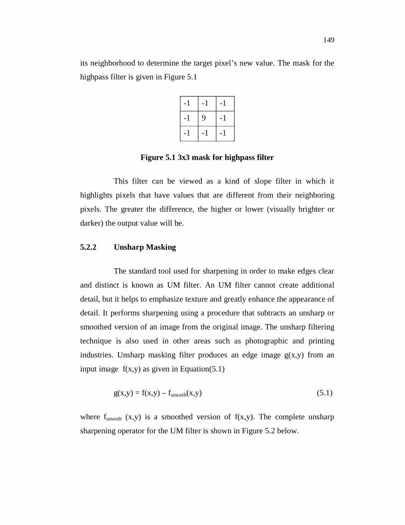
its neighborhood to determine the target pixel’s new value. The mask for the
highpass filter is given in Figure 5.1
-1 -1 -1
-1 9 -1
-1 -1 -1
Figure 5.1 3x3 mask for highpass filter
This filter can be viewed as a kind of slope filter in which it
highlights pixels that have values that are different from their neighboring
pixels. The greater the difference, the higher or lower (visually brighter or
darker) the output value will be.
5.2.2 Unsharp Masking
The standard tool used for sharpening in order to make edges clear
and distinct is known as UM filter. An UM filter cannot create additional
detail, but it helps to emphasize texture and greatly enhance the appearance of
detail. It performs sharpening using a procedure that subtracts an unsharp or
smoothed version of an image from the original image. The unsharp filtering
technique is also used in other areas such as photographic and printing
industries. Unsharp masking filter produces an edge image g(x,y) from an
input image f(x,y) as given in Equation(5.1)
g(x,y) = f(x,y) – fsmooth(x,y) (5.1)
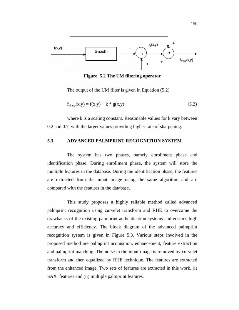
where fsmooth (x,y) is a smoothed version of f(x,y). The complete unsharp
sharpening operator for the UM filter is shown in Figure 5.2 below.
150
Figure 5.2 The UM filtering operator
The output of the UM filter is given in Equation (5.2)
fsharp(x,y) = f(x,y) + k * g(x,y) (5.2)
where k is a scaling constant. Reasonable values for k vary between
0.2 and 0.7, with the larger values providing higher rate of sharpening.
5.3 ADVANCED PALMPRINT RECOGNITION SYSTEM
The system has two phases, namely enrollment phase and
identification phase. During enrollment phase, the system will store the
multiple features in the database. During the identification phase, the features
are extracted from the input image using the same algorithm and are
compared with the features in the database.
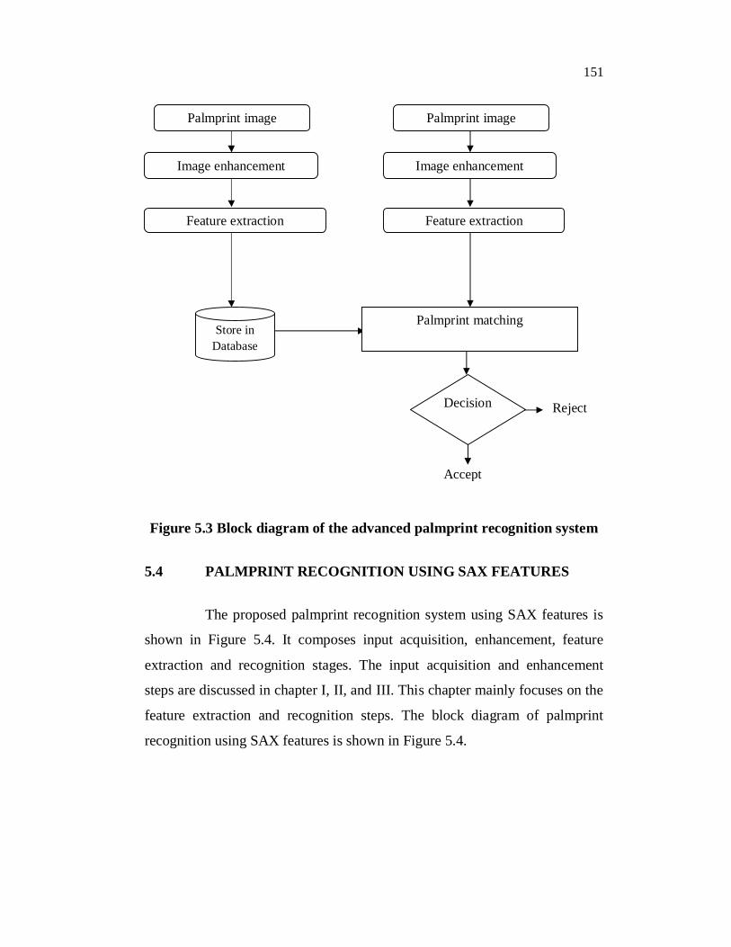
This study proposes a highly reliable method called advanced
palmprint recognition using curvelet transform and RHE to overcome the
drawbacks of the existing palmprint authentication systems and ensures high
accuracy and efficiency. The block diagram of the advanced palmprint
recognition system is given in Figure 5.3. Various steps involved in the
proposed method are palmprint acquisition, enhancement, feature extraction
and palmprint matching. The noise in the input image is removed by curvelet
transform and then equalized by RHE technique. The features are extracted
from the enhanced image. Two sets of features are extracted in this work, (i)
SAX features and (ii) multiple palmprint features.
Smooth + +f(x,y)
fsharp(x,y)
g(x,y) -
+ +
+
151
Figure 5.3 Block diagram of the advanced palmprint recognition system
5.4 PALMPRINT RECOGNITION USING SAX FEATURES
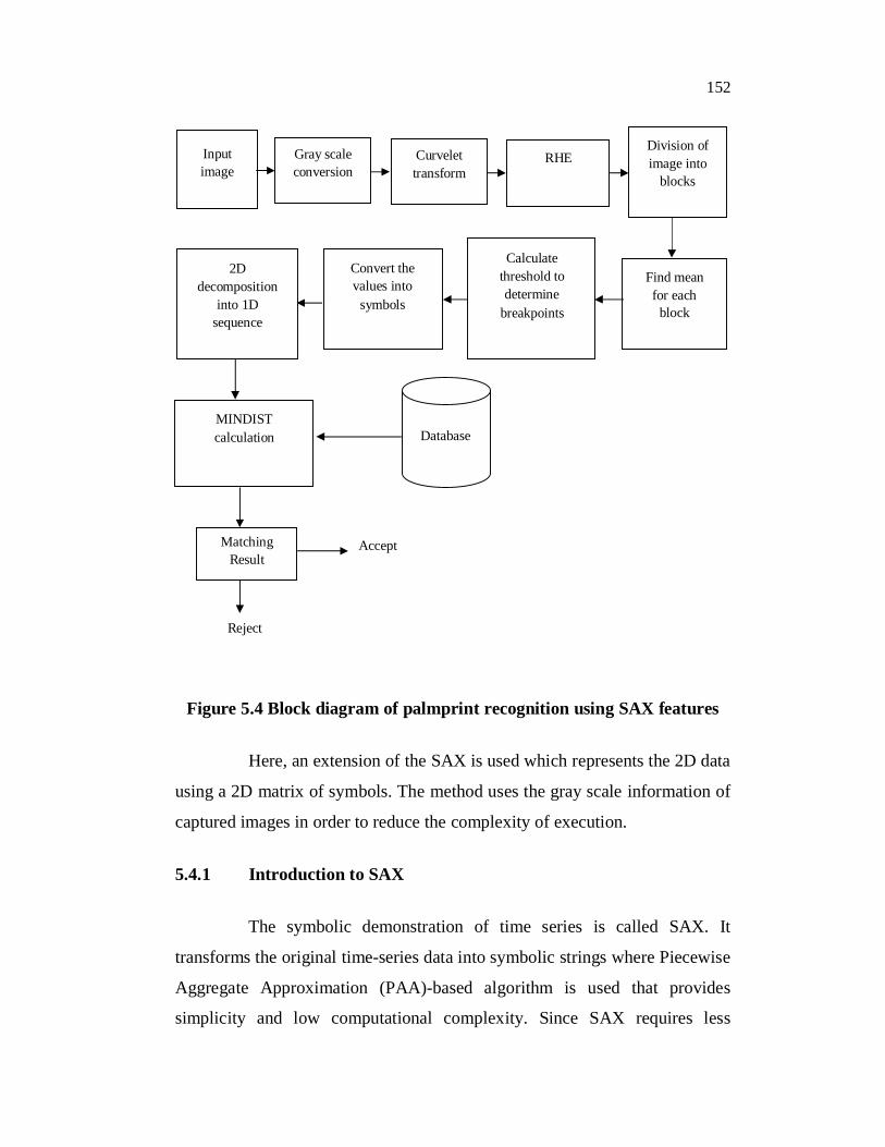
The proposed palmprint recognition system using SAX features is
shown in Figure 5.4. It composes input acquisition, enhancement, feature
extraction and recognition stages. The input acquisition and enhancement
steps are discussed in chapter I, II, and III. This chapter mainly focuses on the
feature extraction and recognition steps. The block diagram of palmprint
recognition using SAX features is shown in Figure 5.4.
Accept
Reject
Palmprint image
Image enhancement
Feature extraction
Store in Database
Palmprint image
Image enhancement
Feature extraction
Palmprint matching
Decision
152
Figure 5.4 Block diagram of palmprint recognition using SAX features
Here, an extension of the SAX is used which represents the 2D data
using a 2D matrix of symbols. The method uses the gray scale information of
captured images in order to reduce the complexity of execution.
5.4.1 Introduction to SAX
The symbolic demonstration of time series is called SAX. It
transforms the original time-series data into symbolic strings where Piecewise
Aggregate Approximation (PAA)-based algorithm is used that provides
simplicity and low computational complexity. Since SAX requires less
Reject
Database MINDIST calculation
Matching Result
Accept
Input image
Gray scale conversion
Curvelet transform
RHE Division of image into
blocks
Find mean for each
block
Calculate threshold to determine
breakpoints
Convert the values into
symbols
2Ddecomposition
into 1D sequence
153
storage space, it is used for solving many challenges associated with the
present data mining tasks. In addition, the symbolic representation allows
researchers go further to the available wealth of data structures and string
manipulation algorithms in computer science, and also for many applications
in bioinformatics and data mining (Wang et al 2004).
SAX algorithm transforms a time-series X of length ‘n’ into the
string of arbitrary length w, where w < n, using a table that contains the
breakpoints. Each value in the table corresponds to each level in the time
series graph which is further represented by symbols in the alphabet array of
size >2 which finally forms the string of length ‘w’. Dimensionality reduction
is based on two parameters named ‘sax length’ (w) and ‘number of symbols
used in the alphabet array’. The algorithm consists of two steps. In the first
step, it transforms the original time-series into a PAA representation ( C ) and
this intermediate representation is further converted into alphabetic string ( C )
in the second step. Usage of PAA approach in the first step gives the
advantage of being simple and efficient in dimensionality reduction and
provides lower bounding property. The second step, where the actual
conversion of PAA coefficients into alphabets is also computationally
efficient, shows the contractive property of symbolic distance.
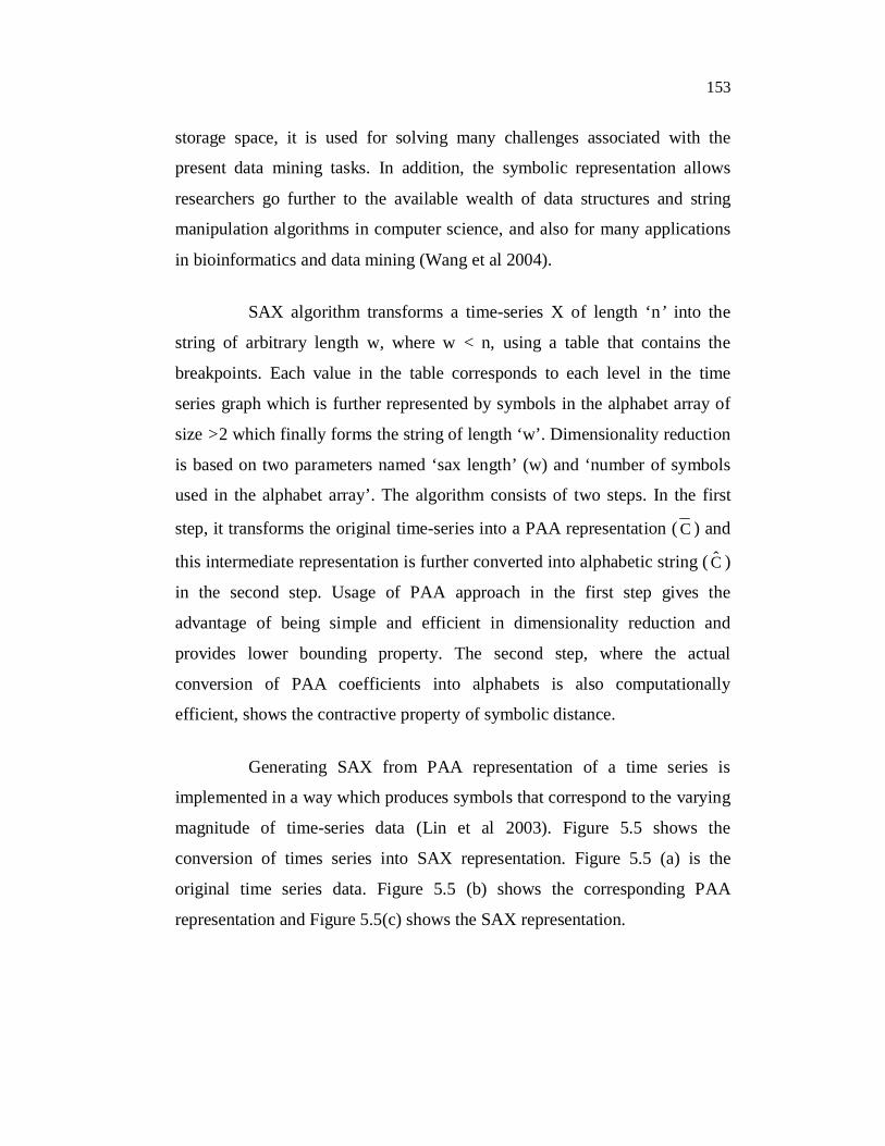
Generating SAX from PAA representation of a time series is
implemented in a way which produces symbols that correspond to the varying
magnitude of time-series data (Lin et al 2003). Figure 5.5 shows the
conversion of times series into SAX representation. Figure 5.5 (a) is the
original time series data. Figure 5.5 (b) shows the corresponding PAA
representation and Figure 5.5(c) shows the SAX representation.
154
(a) (b)
(c)
Figure 5.5 Times series to SAX representation (a) Time series (b) PAA representation (c) SAX representation
5.4.2 2D SAX Representation for the Proposed System
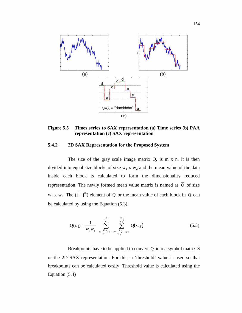
The size of the gray scale image matrix Q, is m x n. It is then
divided into equal size blocks of size w1 x w2 and the mean value of the data
inside each block is calculated to form the dimensionality reduced
representation. The newly formed mean value matrix is named as Q of size
w1 x w2. The (ith, jth) element of Q or the mean value of each block in Q can
be calculated by using the Equation (5.3)
iwm
11iwmx
jwn
11jwny21
1
1
2
2
yx,Qw
1j)(i,Qw
(5.3)
Breakpoints have to be applied to convert Q into a symbol matrix S
or the 2D SAX representation. For this, a ‘threshold’ value is used so that
breakpoints can be calculated easily. Threshold value is calculated using the
Equation (5.4)
155
SAX
minmaxTlevel
(5.4)
where ‘max’ is the maximum value in the Q matrix, ‘min’ is the minimum
value in the Q matrix, and SAXlevel is equal to number of symbols to be used.
For example, if four SAXlevel are chosen, five breakpoints have to
be calculated. The breakpoints are min, min+T, min+2T, min+3T and max.
Then, one symbol is used to represent the values between min and min+T,
and another symbol is used for the values between min+T and min+2T and so
on. In this manner, the symbol matrix S, the 2D SAX representation can be
obtained. Then, this two dimensional data is decomposed into one
dimensional (1D) sequences using a progressive scan (Chen et al 2010).
These 2D SAX representations as strings are stored in the database as
palmprint template.
5.4.3 Palmprint Matching
The MINDIST between two corresponding strings is measured and
this is adopted as the similarity measurement of the corresponding two
palmprints. Given two SAX strings 21ww1211 q,...q,qQ and
21ww1211 c,...c,cC ,
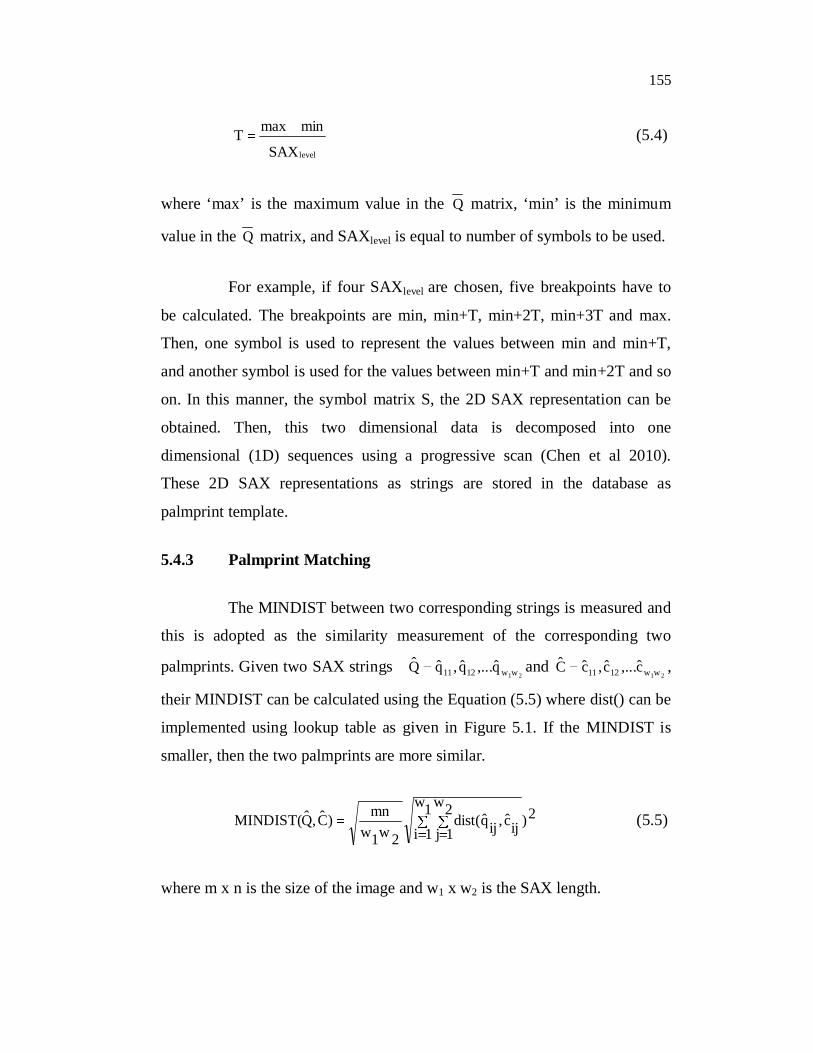
their MINDIST can be calculated using the Equation (5.5) where dist() can be
implemented using lookup table as given in Figure 5.1. If the MINDIST is
smaller, then the two palmprints are more similar.
2)1w
1i2w
1j ijc,ijqdist(2w1w
mn)C,QMINDIST( (5.5)
where m x n is the size of the image and w1 x w2 is the SAX length.
156
Table 5.1 Lookup table for calculating dist() function with four SAXlevel
a b c da 0 0 0.67 1.34
b 0 0 0 0.67
c 0.67 0 0 0
d 1.34 0.67 0 0
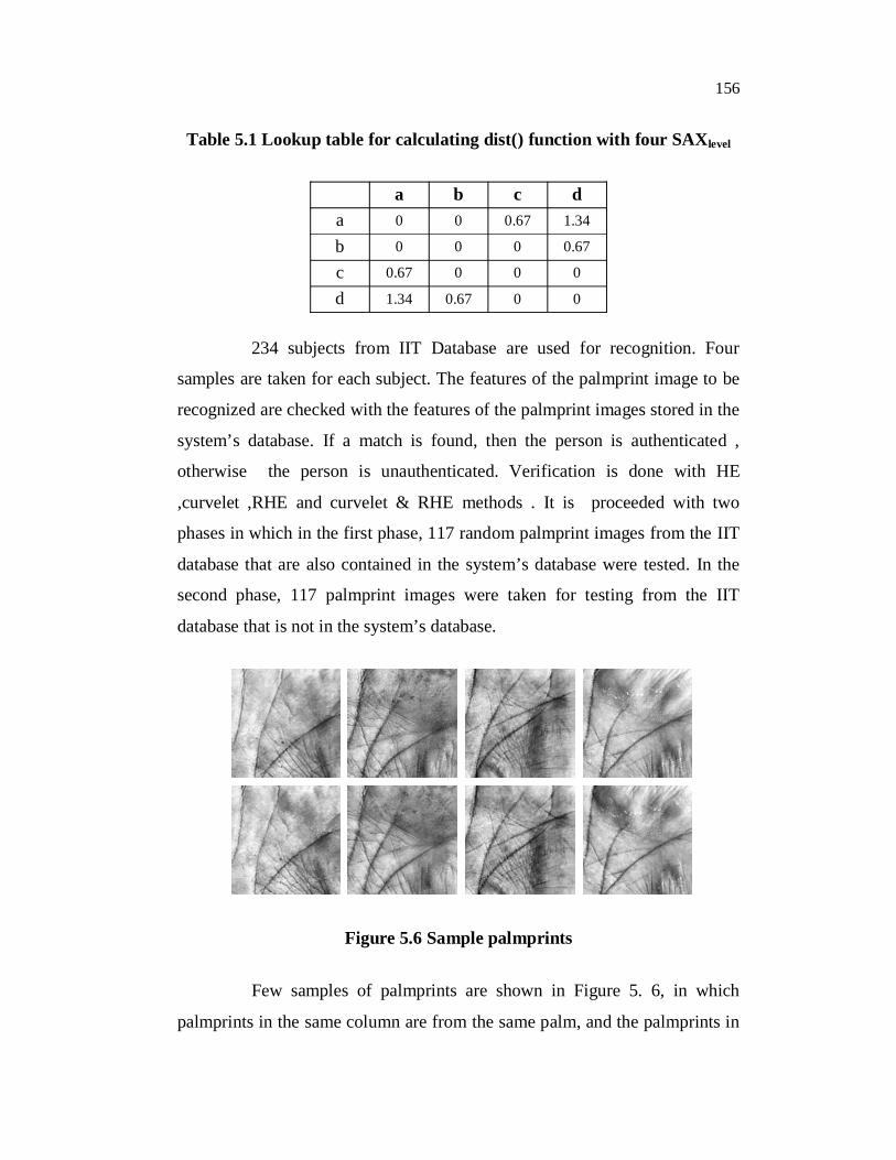
234 subjects from IIT Database are used for recognition. Four
samples are taken for each subject. The features of the palmprint image to be
recognized are checked with the features of the palmprint images stored in the
system’s database. If a match is found, then the person is authenticated ,
otherwise the person is unauthenticated. Verification is done with HE
,curvelet ,RHE and curvelet & RHE methods . It is proceeded with two
phases in which in the first phase, 117 random palmprint images from the IIT
database that are also contained in the system’s database were tested. In the
second phase, 117 palmprint images were taken for testing from the IIT
database that is not in the system’s database.
Figure 5.6 Sample palmprints
Few samples of palmprints are shown in Figure 5. 6, in which
palmprints in the same column are from the same palm, and the palmprints in
157
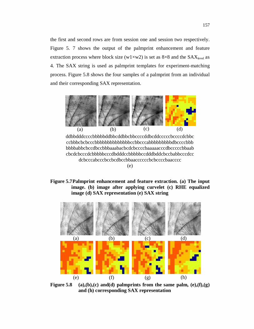
the first and second rows are from session one and session two respectively.
Figure 5. 7 shows the output of the palmprint enhancement and feature
extraction process where block size (w1×w2) is set as 8×8 and the SAXlevel as
4. The SAX string is used as palmprint templates for experiment-matching
process. Figure 5.8 shows the four samples of a palmprint from an individual
and their corresponding SAX representation.
(a) (b) (c) (d)ddbbdddccccbbbbbddbbcddbbcbbccccddbcddcccccbccccdcbbcccbbbcbcbcccbbbbbbbbbbbbbbccbbcccabbbbbbbbbdbccccbbbbbbbabbcbccdbccbbbaaabacbcdcbccccbaaaaacccdbcccccbbaabcbcdcbcccdcbbbbbcccdbdddccbbbbbccdddbddcbccbabbcccdcc
dcbcccabcccbccbcdbccbbaaccccccbcbccccbaacccc (e)
Figure 5.7 Palmprint enhancement and feature extraction. (a) The input image. (b) image after applying curvelet (c) RHE equalized image (d) SAX representation (e) SAX string
(a) (b) (c) (d)
(e) (f) (g) (h)Figure 5.8 (a),(b),(c) and(d) palmprints from the same palm, (e),(f),(g)
and (h) corresponding SAX representation
158
5.5 PALMPRINT RECOGNITION USING MULTIPLE
PALMPRINT FEATURES
This system uses a combination of four major representations of the
palmprint. i.e Discrete Cosine Transform (DCT), Local Binary Pattern (LBP),
GB (Gabor features) and line features. The sum rule is used for fusing
multiple features of the palmprint. Decision will be taken based on the
distance between the input image features and features of the images in the
database. Here, the first stage of the system is to perform the enhancement of
the palmprint image. Curvelet, RHE and highpass filter are used for
enhancement of the palmprint image.
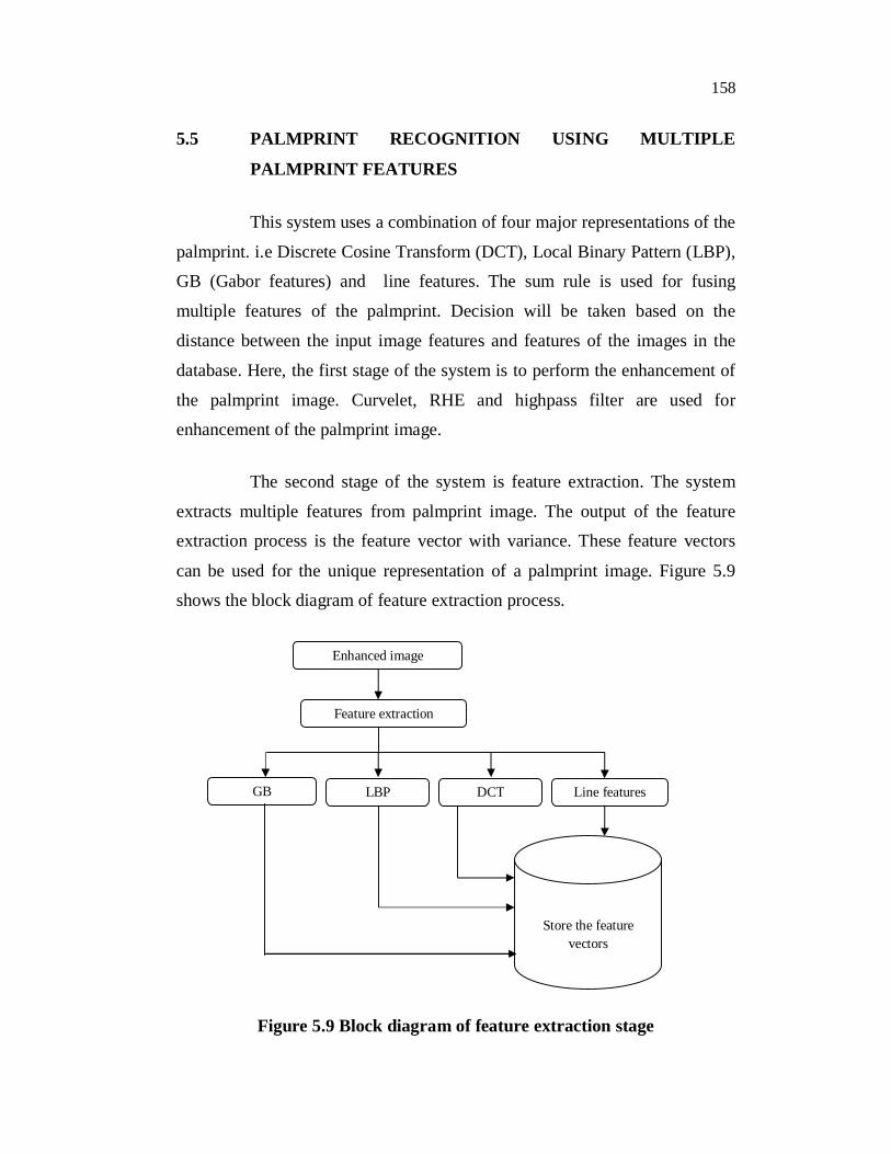
The second stage of the system is feature extraction. The system
extracts multiple features from palmprint image. The output of the feature
extraction process is the feature vector with variance. These feature vectors
can be used for the unique representation of a palmprint image. Figure 5.9
shows the block diagram of feature extraction process.
Figure 5.9 Block diagram of feature extraction stage
Enhanced image
Feature extraction
GB LBP DCT Line features
Store the feature vectors
159
5.5.1 Extraction of Gabor Features
Gabor filter is a linear filter used for edge detection. Frequency and
orientation representations of Gabor filters are similar to those of the human
visual system, and they have been found to be particularly appropriate for
texture representation and discrimination. In the spatial domain, a 2D Gabor
filter is a Gaussian kernel function modulated by a sinusoidal plane wave. The
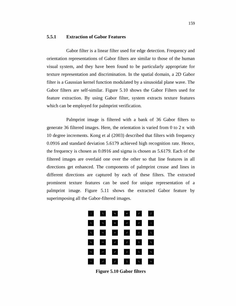
Gabor filters are self-similar. Figure 5.10 shows the Gabor Filters used for
feature extraction. By using Gabor filter, system extracts texture features
which can be employed for palmprint verification.
Palmprint image is filtered with a bank of 36 Gabor filters to
generate 36 filtered images. Here, the orientation is varied from 0 to 2 with
10 degree increments. Kong et al (2003) described that filters with frequency
0.0916 and standard deviation 5.6179 achieved high recognition rate. Hence,
the frequency is chosen as 0.0916 and sigma is chosen as 5.6179. Each of the
filtered images are overlaid one over the other so that line features in all
directions get enhanced. The components of palmprint crease and lines in
different directions are captured by each of these filters. The extracted
prominent texture features can be used for unique representation of a
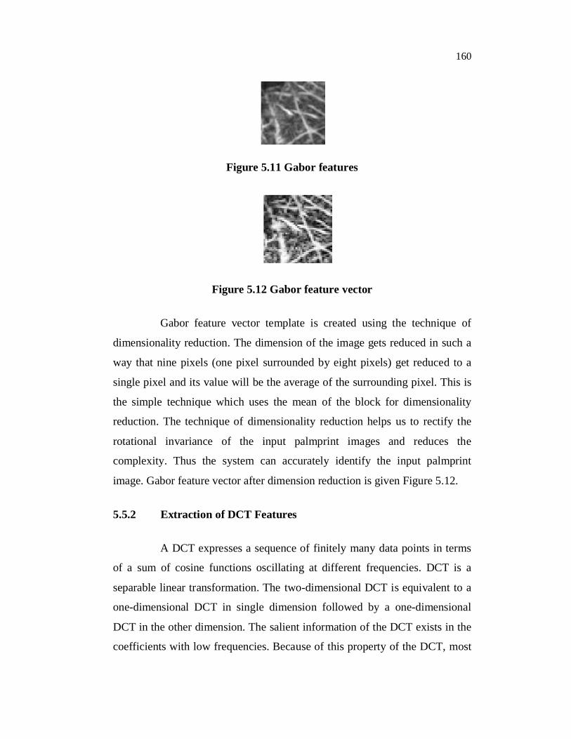
palmprint image. Figure 5.11 shows the extracted Gabor feature by
superimposing all the Gabor-filtered images.
Figure 5.10 Gabor filters
160
Figure 5.11 Gabor features
Figure 5.12 Gabor feature vector
Gabor feature vector template is created using the technique of
dimensionality reduction. The dimension of the image gets reduced in such a
way that nine pixels (one pixel surrounded by eight pixels) get reduced to a
single pixel and its value will be the average of the surrounding pixel. This is
the simple technique which uses the mean of the block for dimensionality
reduction. The technique of dimensionality reduction helps us to rectify the
rotational invariance of the input palmprint images and reduces the
complexity. Thus the system can accurately identify the input palmprint
image. Gabor feature vector after dimension reduction is given Figure 5.12.
5.5.2 Extraction of DCT Features
A DCT expresses a sequence of finitely many data points in terms
of a sum of cosine functions oscillating at different frequencies. DCT is a
separable linear transformation. The two-dimensional DCT is equivalent to a
one-dimensional DCT in single dimension followed by a one-dimensional
DCT in the other dimension. The salient information of the DCT exists in the
coefficients with low frequencies. Because of this property of the DCT, most
161
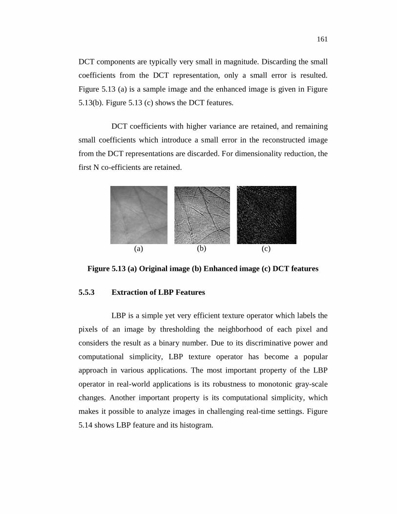
DCT components are typically very small in magnitude. Discarding the small
coefficients from the DCT representation, only a small error is resulted.
Figure 5.13 (a) is a sample image and the enhanced image is given in Figure
5.13(b). Figure 5.13 (c) shows the DCT features.
DCT coefficients with higher variance are retained, and remaining
small coefficients which introduce a small error in the reconstructed image
from the DCT representations are discarded. For dimensionality reduction, the
first N co-efficients are retained.
(a) (b) (c)
Figure 5.13 (a) Original image (b) Enhanced image (c) DCT features
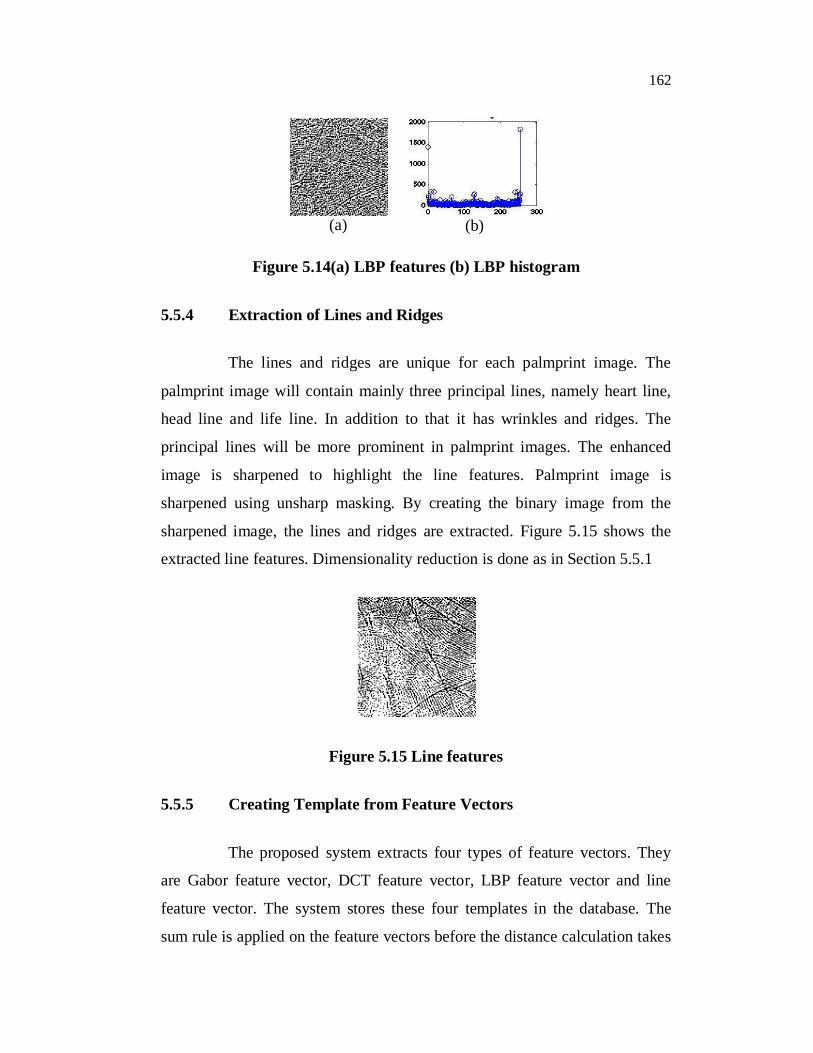
5.5.3 Extraction of LBP Features
LBP is a simple yet very efficient texture operator which labels the
pixels of an image by thresholding the neighborhood of each pixel and
considers the result as a binary number. Due to its discriminative power and
computational simplicity, LBP texture operator has become a popular
approach in various applications. The most important property of the LBP
operator in real-world applications is its robustness to monotonic gray-scale
changes. Another important property is its computational simplicity, which
makes it possible to analyze images in challenging real-time settings. Figure
5.14 shows LBP feature and its histogram.
162
(a) (b)
Figure 5.14(a) LBP features (b) LBP histogram
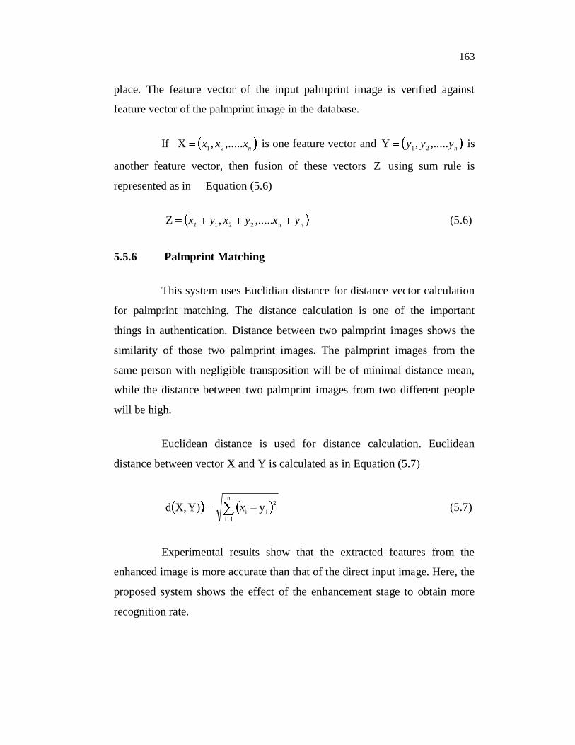
5.5.4 Extraction of Lines and Ridges
The lines and ridges are unique for each palmprint image. The
palmprint image will contain mainly three principal lines, namely heart line,
head line and life line. In addition to that it has wrinkles and ridges. The
principal lines will be more prominent in palmprint images. The enhanced
image is sharpened to highlight the line features. Palmprint image is
sharpened using unsharp masking. By creating the binary image from the
sharpened image, the lines and ridges are extracted. Figure 5.15 shows the
extracted line features. Dimensionality reduction is done as in Section 5.5.1
Figure 5.15 Line features
5.5.5 Creating Template from Feature Vectors
The proposed system extracts four types of feature vectors. They
are Gabor feature vector, DCT feature vector, LBP feature vector and line
feature vector. The system stores these four templates in the database. The
sum rule is applied on the feature vectors before the distance calculation takes
163
place. The feature vector of the input palmprint image is verified against
feature vector of the palmprint image in the database.
If nxxx ,.....,X 21 is one feature vector and nyyy ,.....,Y 21 is
another feature vector, then fusion of these vectors Z using sum rule is
represented as in Equation (5.6)
n1 yxyxyx n221 ,.....,Z (5.6)
5.5.6 Palmprint Matching
This system uses Euclidian distance for distance vector calculation
for palmprint matching. The distance calculation is one of the important
things in authentication. Distance between two palmprint images shows the
similarity of those two palmprint images. The palmprint images from the
same person with negligible transposition will be of minimal distance mean,
while the distance between two palmprint images from two different people
will be high.
Euclidean distance is used for distance calculation. Euclidean
distance between vector X and Y is calculated as in Equation (5.7)
n
1i
2ii y)Y,Xd x (5.7)
Experimental results show that the extracted features from the
enhanced image is more accurate than that of the direct input image. Here, the
proposed system shows the effect of the enhancement stage to obtain more
recognition rate.
164
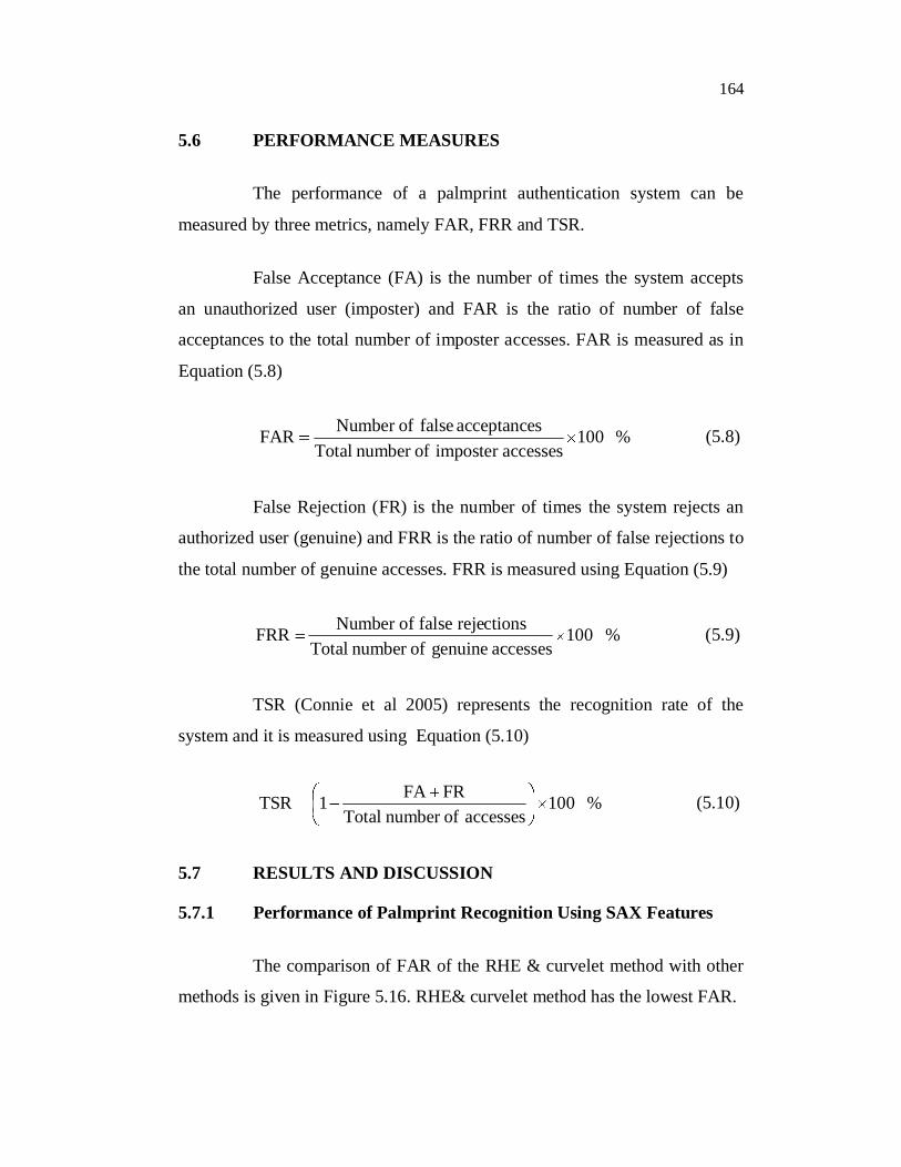
5.6 PERFORMANCE MEASURES
The performance of a palmprint authentication system can be
measured by three metrics, namely FAR, FRR and TSR.
False Acceptance (FA) is the number of times the system accepts
an unauthorized user (imposter) and FAR is the ratio of number of false
acceptances to the total number of imposter accesses. FAR is measured as in
Equation (5.8)
%100accessesimposter ofnumber Total
sacceptancefalseofNumber FAR (5.8)
False Rejection (FR) is the number of times the system rejects an
authorized user (genuine) and FRR is the ratio of number of false rejections to
the total number of genuine accesses. FRR is measured using Equation (5.9)
%100accessesgenuineofnumber Total
ctionsfalse rejeNumber of FRR (5.9)
TSR (Connie et al 2005) represents the recognition rate of the
system and it is measured using Equation (5.10)
%100accessesofnumber Total
FRFA1TSR (5.10)
5.7 RESULTS AND DISCUSSION
5.7.1 Performance of Palmprint Recognition Using SAX Features
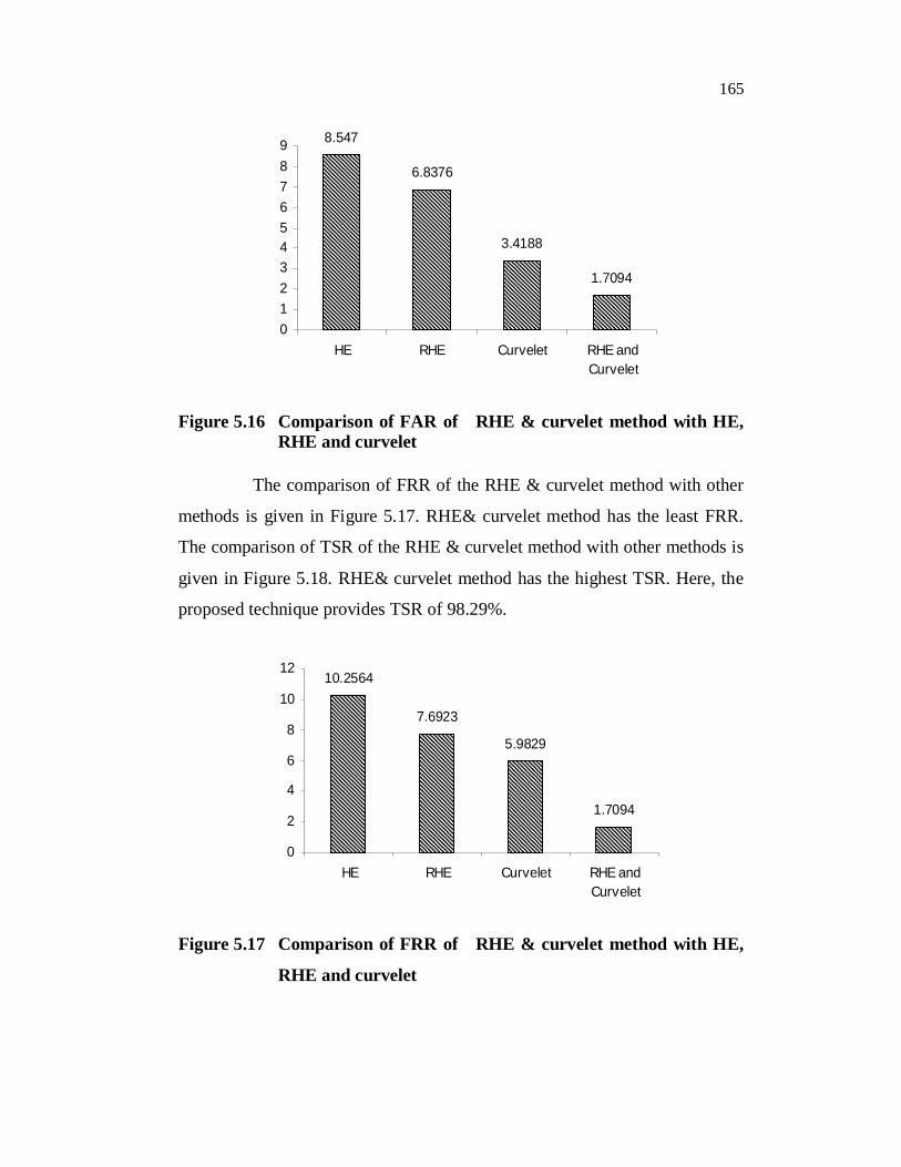
The comparison of FAR of the RHE & curvelet method with other
methods is given in Figure 5.16. RHE& curvelet method has the lowest FAR.
165
8.547
6.8376
3.4188
1.7094
0123456789
HE RHE Curvelet RHE andCurvelet
Figure 5.16 Comparison of FAR of RHE & curvelet method with HE, RHE and curvelet
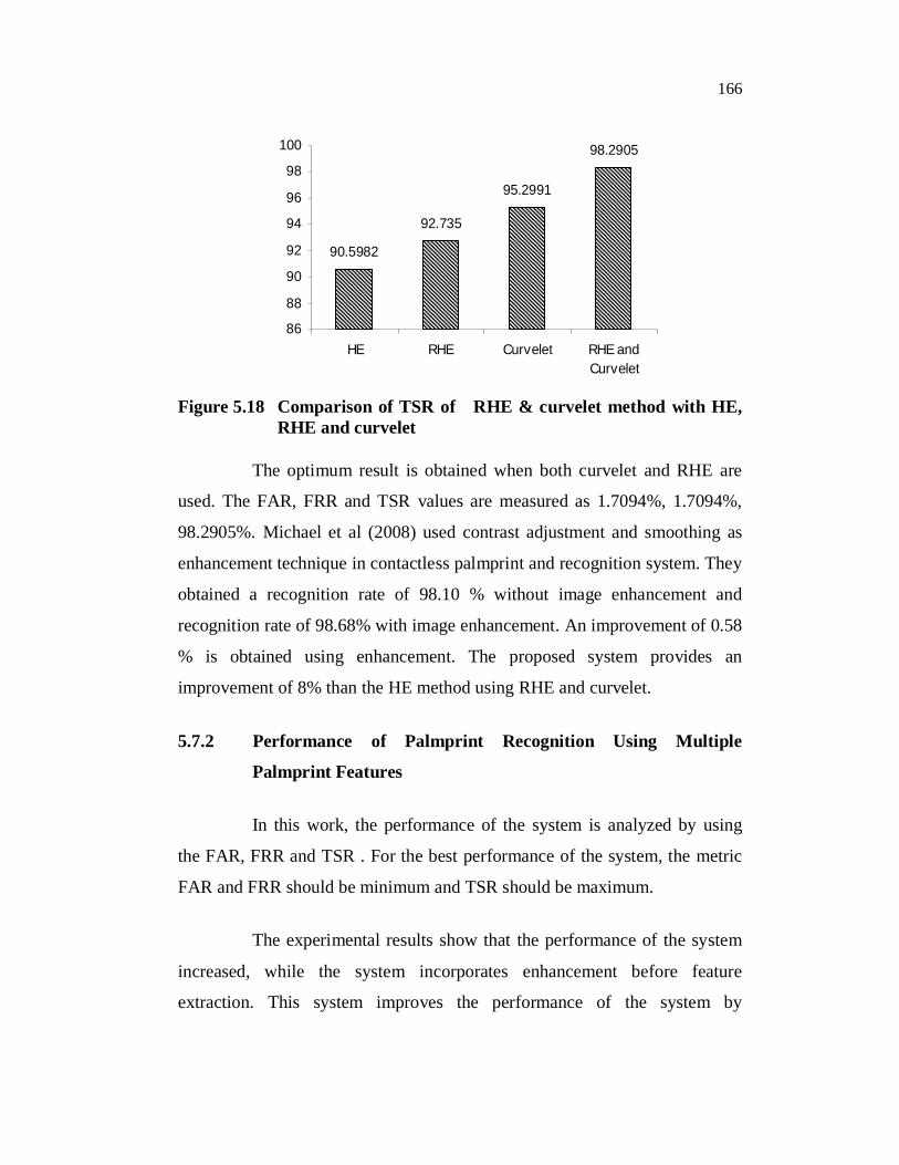
The comparison of FRR of the RHE & curvelet method with other
methods is given in Figure 5.17. RHE& curvelet method has the least FRR.
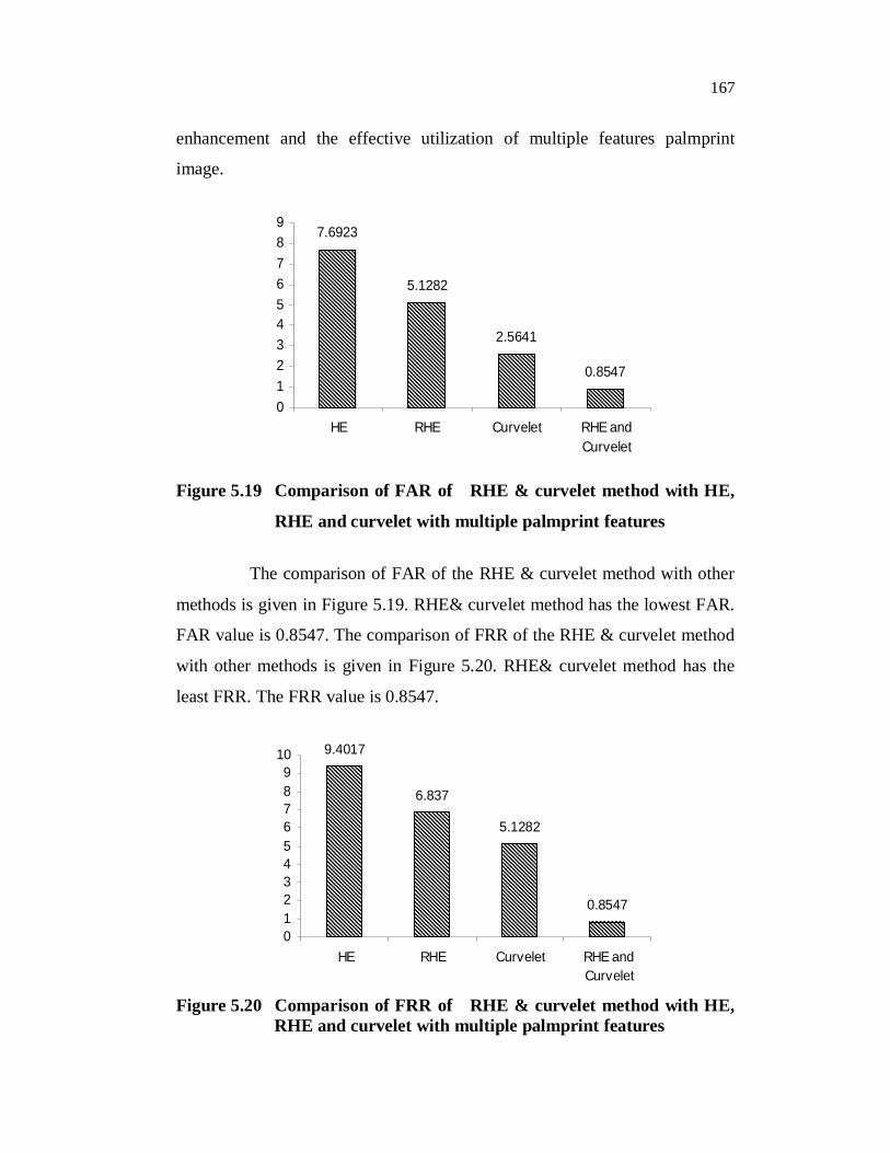
The comparison of TSR of the RHE & curvelet method with other methods is
given in Figure 5.18. RHE& curvelet method has the highest TSR. Here, the
proposed technique provides TSR of 98.29%.
10.2564
7.6923
5.9829
1.7094
0
2
4
6
8
10
12
HE RHE Curvelet RHE andCurvelet
Figure 5.17 Comparison of FRR of RHE & curvelet method with HE,
RHE and curvelet
166
90.5982
92.735
95.2991
98.2905
86
88
90
92
94
96
98
100
HE RHE Curvelet RHE andCurvelet
Figure 5.18 Comparison of TSR of RHE & curvelet method with HE, RHE and curvelet
The optimum result is obtained when both curvelet and RHE are
used. The FAR, FRR and TSR values are measured as 1.7094%, 1.7094%,
98.2905%. Michael et al (2008) used contrast adjustment and smoothing as
enhancement technique in contactless palmprint and recognition system. They
obtained a recognition rate of 98.10 % without image enhancement and
recognition rate of 98.68% with image enhancement. An improvement of 0.58
% is obtained using enhancement. The proposed system provides an
improvement of 8% than the HE method using RHE and curvelet.
5.7.2 Performance of Palmprint Recognition Using Multiple
Palmprint Features
In this work, the performance of the system is analyzed by using
the FAR, FRR and TSR . For the best performance of the system, the metric
FAR and FRR should be minimum and TSR should be maximum.
The experimental results show that the performance of the system
increased, while the system incorporates enhancement before feature
extraction. This system improves the performance of the system by
167
enhancement and the effective utilization of multiple features palmprint
image.
7.6923
5.1282
2.5641
0.8547
0123456789
HE RHE Curvelet RHE andCurvelet
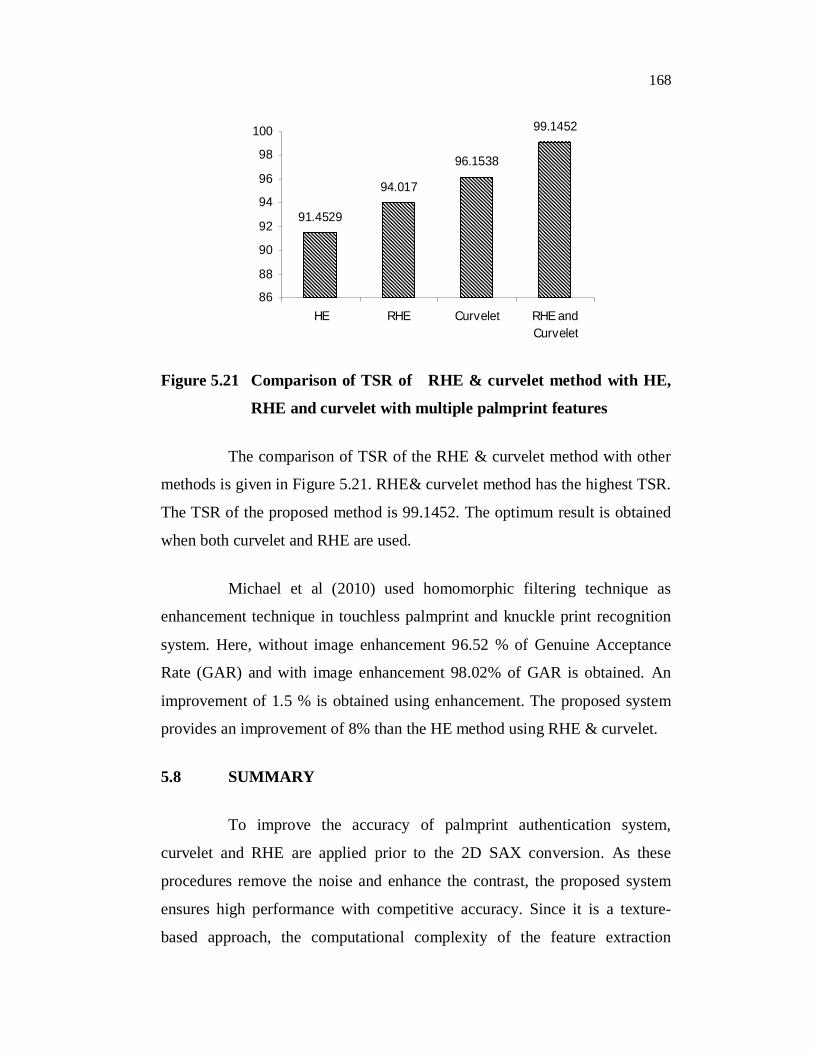
Figure 5.19 Comparison of FAR of RHE & curvelet method with HE,
RHE and curvelet with multiple palmprint features
The comparison of FAR of the RHE & curvelet method with other
methods is given in Figure 5.19. RHE& curvelet method has the lowest FAR.
FAR value is 0.8547. The comparison of FRR of the RHE & curvelet method
with other methods is given in Figure 5.20. RHE& curvelet method has the
least FRR. The FRR value is 0.8547.
9.4017
6.837
5.1282
0.8547
0123456789
10
HE RHE Curvelet RHE andCurvelet
Figure 5.20 Comparison of FRR of RHE & curvelet method with HE, RHE and curvelet with multiple palmprint features
168
91.4529
94.017
96.1538
99.1452
86
88
90
92
94
96
98
100
HE RHE Curvelet RHE andCurvelet
Figure 5.21 Comparison of TSR of RHE & curvelet method with HE,
RHE and curvelet with multiple palmprint features
The comparison of TSR of the RHE & curvelet method with other
methods is given in Figure 5.21. RHE& curvelet method has the highest TSR.
The TSR of the proposed method is 99.1452. The optimum result is obtained
when both curvelet and RHE are used.
Michael et al (2010) used homomorphic filtering technique as
enhancement technique in touchless palmprint and knuckle print recognition
system. Here, without image enhancement 96.52 % of Genuine Acceptance
Rate (GAR) and with image enhancement 98.02% of GAR is obtained. An
improvement of 1.5 % is obtained using enhancement. The proposed system
provides an improvement of 8% than the HE method using RHE & curvelet.
5.8 SUMMARY
To improve the accuracy of palmprint authentication system,
curvelet and RHE are applied prior to the 2D SAX conversion. As these
procedures remove the noise and enhance the contrast, the proposed system
ensures high performance with competitive accuracy. Since it is a texture-
based approach, the computational complexity of the feature extraction
169
process is much lower and thus can be efficiently implemented for even slow
mobile embedded platforms. Also, the proposed approach does not rely on
any parameter training process. A palmprint authentication system using
multiple palmprint features with enhancement is proposed in this work. It uses
four different features from the palmprint image, namely GB, DCT, LBP and
line feature. RHE and curvelet are used for enhancement. The experimental
results demonstrated that the RHE & curvelet method achieves optimum
performance comparison with the other ones.
Recommended


![Decade progress of palmprint recognition: A brief surveyancai/DIP/articole/Decade progress of... · [3], palm vein [4] , palmprint [5] and other features [6] in personal verification](https://img.pdfslide.net/doc/110x75/5eab5f0c020b347f2957d1ea/decade-progress-of-palmprint-recognition-a-brief-survey-ancaidiparticoledecade.jpg)
![Towards contactless palmprint recognition: A novel device, a ......200 L. Zhang et al. / Pattern Recognition 69 (2017) 199–212 palmprint acquisition device proposed in [16]), which](https://img.pdfslide.net/doc/110x75/5ffb25f99dca987aeb23ad29/towards-contactless-palmprint-recognition-a-novel-device-a-200-l-zhang.jpg)


![PALMPRINT RECOGNITION SYSTEM BASED ON ...jestec.taylors.edu.my/Vol 16 issue 1 February 2021/16_1...Fei et al. [9] proposed palmprint recognition system based on -layer a double direction](https://img.pdfslide.net/doc/110x75/6103386614f0034981267cad/palmprint-recognition-system-based-on-16-issue-1-february-2021161-fei-et.jpg)